


AT-Commands Manual
PC Cards GC75, GC79, GC82, GC83, GC85 and GC89
EN/LZT 123 928 R2A

Contents
General . . . . . . . . . . . . . . . . . . . . . . . . . . . . . . . . . . . . . . . . . . . . . . . . . . . 9
Alphabet . . . . . . . . . . . . . . . . . . . . . . . . . . . . . . . . . . . . . . . . . . . . . . . . 9
DTE command lines . . . . . . . . . . . . . . . . . . . . . . . . . . . . . . . . . . . . . . . 9
Command line general format . . . . . . . . . . . . . . . . . . . . . . . . . . . . . . . 9
Command line editing . . . . . . . . . . . . . . . . . . . . . . . . . . . . . . . . . . . . . 10
Command line echo . . . . . . . . . . . . . . . . . . . . . . . . . . . . . . . . . . . . . . . 10
Types of TE Commands. . . . . . . . . . . . . . . . . . . . . . . . . . . . . . . . . . . . 10
TE Command . . . . . . . . . . . . . . . . . . . . . . . . . . . . . . . . . . . . . . . . . . . . 10
Basic Command . . . . . . . . . . . . . . . . . . . . . . . . . . . . . . . . . . . . . . . . . . 11
Extended commands. . . . . . . . . . . . . . . . . . . . . . . . . . . . . . . . . . . . . . . 12
Action Command . . . . . . . . . . . . . . . . . . . . . . . . . . . . . . . . . . . . . . . . . 14
Parameter Command . . . . . . . . . . . . . . . . . . . . . . . . . . . . . . . . . . . . . . 15
Concatenating commands after extended syntax commands . . . . . . . . 16
Concatenating commands after basic format commands . . . . . . . . . . . 17
Issuing commands . . . . . . . . . . . . . . . . . . . . . . . . . . . . . . . . . . . . . . . . 17
Executing commands . . . . . . . . . . . . . . . . . . . . . . . . . . . . . . . . . . . . . . 17
TA responses . . . . . . . . . . . . . . . . . . . . . . . . . . . . . . . . . . . . . . . . . . . . 18
In-band Escape mechanism . . . . . . . . . . . . . . . . . . . . . . . . . . . . . . . . . 21
Control and Identification Commands . . . . . . . . . . . . . . . . . . . . . . . . . 23
Z - Reset to Factory Defined Configuration. . . . . . . . . . . . . . . . . . . . . 23
&F - Reset to Default Configuration . . . . . . . . . . . . . . . . . . . . . . . . . . 24
I - Request HW Version . . . . . . . . . . . . . . . . . . . . . . . . . . . . . . . . . . . . 24
+CGMI (+GMI) - Request Manufacturer Identification . . . . . . . . . . . 25
+CGMM (+GMM) - Request Model Id . . . . . . . . . . . . . . . . . . . . . . . . 26
+CGMR (+GMR) - Request Revision Id . . . . . . . . . . . . . . . . . . . . . . . 27
+CLAC - List All Available AT Commands. . . . . . . . . . . . . . . . . . . . 27
* - List All AT Commands. . . . . . . . . . . . . . . . . . . . . . . . . . . . . . . . . . 28
+GCAP - Request Modem Capability List. . . . . . . . . . . . . . . . . . . . . . 28
+WS46 - select wireless network (PCCA STD-101) . . . . . . . . . . . . . . 29
*MCNFG - Module Configuration Change . . . . . . . . . . . . . . . . . . . . . 29
*MRDY - Module Ready Status . . . . . . . . . . . . . . . . . . . . . . . . . . . . . 31
+CCLK - Set Real Time Clock. . . . . . . . . . . . . . . . . . . . . . . . . . . . . . . 31
Call Control . . . . . . . . . . . . . . . . . . . . . . . . . . . . . . . . . . . . . . . . . . . . . . . 33
A - Answer . . . . . . . . . . . . . . . . . . . . . . . . . . . . . . . . . . . . . . . . . . . . . . 33
H - Hang up . . . . . . . . . . . . . . . . . . . . . . . . . . . . . . . . . . . . . . . . . . . . . 34
D - Dial (non GPRS calls) . . . . . . . . . . . . . . . . . . . . . . . . . . . . . . . . . . 34
<Dial-string> Parameter . . . . . . . . . . . . . . . . . . . . . . . . . . . . . . . . . . . . 35
MT originated PDP context activation . . . . . . . . . . . . . . . . . . . . . . . . . 36
D*99* - Request GPRS service . . . . . . . . . . . . . . . . . . . . . . . . . . . . . . 36
D*98* - Request GPRS IP service . . . . . . . . . . . . . . . . . . . . . . . . . . . . 38
Network requested PDP context activation . . . . . . . . . . . . . . . . . . . . . 39
S0 - Automatic response to a network
request for PDP context activation. . . . . . . . . . . . . . . . . . . . . . . . . . . . 39
A - Manual acceptance of a network
2

request for PDP context activation. . . . . . . . . . . . . . . . . . . . . . . . . . . . 39
H - Manual rejection of a network
request for PDP context activation. . . . . . . . . . . . . . . . . . . . . . . . . . . . 40
L - Monitor Speaker Loudness. . . . . . . . . . . . . . . . . . . . . . . . . . . . . . . 40
+CFUN - Set Phone Functionality . . . . . . . . . . . . . . . . . . . . . . . . . . . . 41
RING - Ring Indication . . . . . . . . . . . . . . . . . . . . . . . . . . . . . . . . . . . . 42
O - Return to On-line Data Mode. . . . . . . . . . . . . . . . . . . . . . . . . . . . . 42
P - Select Pulse Dialing . . . . . . . . . . . . . . . . . . . . . . . . . . . . . . . . . . . . 43
T - Select Tone Dialing . . . . . . . . . . . . . . . . . . . . . . . . . . . . . . . . . . . . 43
+CAOC - Advice of Charge . . . . . . . . . . . . . . . . . . . . . . . . . . . . . . . . . 44
+CACM - Accumulated Call Meter . . . . . . . . . . . . . . . . . . . . . . . . . . . 45
+CAMM - Accumulated Call Meter Maximum. . . . . . . . . . . . . . . . . . 46
+CPUC - Price per unit and currency. . . . . . . . . . . . . . . . . . . . . . . . . . 47
+CCWE - Call Meter Maximum Event . . . . . . . . . . . . . . . . . . . . . . . . 48
+CPWC - Power class . . . . . . . . . . . . . . . . . . . . . . . . . . . . . . . . . . . . . 49
+CPAS - Phone Activity Status . . . . . . . . . . . . . . . . . . . . . . . . . . . . . . 50
+CSTA - Select Type of Address. . . . . . . . . . . . . . . . . . . . . . . . . . . . . 50
+CHUP - Hangup Call . . . . . . . . . . . . . . . . . . . . . . . . . . . . . . . . . . . . . 51
+CKPD - Keypad Control . . . . . . . . . . . . . . . . . . . . . . . . . . . . . . . . . . 51
+CSIM - Generic SIM Access . . . . . . . . . . . . . . . . . . . . . . . . . . . . . . . 53
+CMUT - Mute Control . . . . . . . . . . . . . . . . . . . . . . . . . . . . . . . . . . . . 54
+VTD - Tone Duration. . . . . . . . . . . . . . . . . . . . . . . . . . . . . . . . . . . . . 55
+VTS - DTMF and Tone Generation . . . . . . . . . . . . . . . . . . . . . . . . . . 55
*MTRSH - Refresh Command . . . . . . . . . . . . . . . . . . . . . . . . . . . . . . . 56
*MTRSH - Refresh Unsolicited Response. . . . . . . . . . . . . . . . . . . . . . 57
Interface Commands . . . . . . . . . . . . . . . . . . . . . . . . . . . . . . . . . . . . . . . . 58
+++AT - Escape Sequence Character. . . . . . . . . . . . . . . . . . . . . . . . . . 58
S3 - Command Line Termination Character . . . . . . . . . . . . . . . . . . . . 58
S4 - Response Formatting Character . . . . . . . . . . . . . . . . . . . . . . . . . . 59
S5 - Command Line Editing Character . . . . . . . . . . . . . . . . . . . . . . . . 60
E - Command Echo. . . . . . . . . . . . . . . . . . . . . . . . . . . . . . . . . . . . . . . . 60
Q - Result Code Suppression . . . . . . . . . . . . . . . . . . . . . . . . . . . . . . . . 61
V - TA Response Format . . . . . . . . . . . . . . . . . . . . . . . . . . . . . . . . . . . 61
&C - Circuit 109 (DCD) Control . . . . . . . . . . . . . . . . . . . . . . . . . . . . . 62
&D - Circuit 108 (DTR) Response. . . . . . . . . . . . . . . . . . . . . . . . . . . . 63
+IFC - TE-TA Local Flow Control . . . . . . . . . . . . . . . . . . . . . . . . . . . 64
S0 - Automatic Answer Control. . . . . . . . . . . . . . . . . . . . . . . . . . . . . . 65
S6 - Blind Dial Delay Control . . . . . . . . . . . . . . . . . . . . . . . . . . . . . . . 66
S7 - Connection Completion Timeout . . . . . . . . . . . . . . . . . . . . . . . . . 66
S10 - Automatic Disconnect Delay Control . . . . . . . . . . . . . . . . . . . . . 67
M - Monitor Speaker Control . . . . . . . . . . . . . . . . . . . . . . . . . . . . . . . . 67
X - Call Progress Monitoring Control . . . . . . . . . . . . . . . . . . . . . . . . . 68
+ILRR - TE-TA Local , 4Rate Reporting . . . . . . . . . . . . . . . . . . . . . . 68
Error Control (LAPM/MNP) . . . . . . . . . . . . . . . . . . . . . . . . . . . . . . . . . 70
+ES - Error Control Selection . . . . . . . . . . . . . . . . . . . . . . . . . . . . . . . 70
+ETBM - Call Termination Buffer Management. . . . . . . . . . . . . . . . . 71
+ER - Error Control Reporting. . . . . . . . . . . . . . . . . . . . . . . . . . . . . . . 72
3

Data Compression (V24bis/MNP5) . . . . . . . . . . . . . . . . . . . . . . . . . . . . 73
+DS - Data Compression Mode Selection . . . . . . . . . . . . . . . . . . . . . . 73
+DR - Data Compression Reporting . . . . . . . . . . . . . . . . . . . . . . . . . . 74
Fax Class 2 . . . . . . . . . . . . . . . . . . . . . . . . . . . . . . . . . . . . . . . . . . . . . . . . 75
+FCLASS - Select Mode . . . . . . . . . . . . . . . . . . . . . . . . . . . . . . . . . . . 75
+FBO - Phase C Bit Order Parameter . . . . . . . . . . . . . . . . . . . . . . . . . 76
+FCQ - Copy Quality Checking. . . . . . . . . . . . . . . . . . . . . . . . . . . . . . 77
+FCC - TA Capability Parameter. . . . . . . . . . . . . . . . . . . . . . . . . . . . . 77
+FCS - Current Session Parameter. . . . . . . . . . . . . . . . . . . . . . . . . . . . 79
+FDR - Fax Data Receive Command. . . . . . . . . . . . . . . . . . . . . . . . . . 80
+FDT - Fax Data Transmission Command . . . . . . . . . . . . . . . . . . . . . 81
+FEA - Phase C received EOL alignment . . . . . . . . . . . . . . . . . . . . . . 82
+FET - Page Punctuation . . . . . . . . . . . . . . . . . . . . . . . . . . . . . . . . . . . 82
+FIE - Procedure interrupt enable . . . . . . . . . . . . . . . . . . . . . . . . . . . . 83
+FIP - Initialise Fax Parameters. . . . . . . . . . . . . . . . . . . . . . . . . . . . . . 84
+FIS - Current Session Negotiation Parameter . . . . . . . . . . . . . . . . . . 85
+FIT - Inactivity timeout . . . . . . . . . . . . . . . . . . . . . . . . . . . . . . . . . . . 85
+FKS - Session Termination . . . . . . . . . . . . . . . . . . . . . . . . . . . . . . . . 86
+FLI - Local ID String . . . . . . . . . . . . . . . . . . . . . . . . . . . . . . . . . . . . . 87
+FPI - Local Polling ID String . . . . . . . . . . . . . . . . . . . . . . . . . . . . . . 88
+FLP - Indicated Document to Poll . . . . . . . . . . . . . . . . . . . . . . . . . . . 88
+FNR - Negotiation reporting . . . . . . . . . . . . . . . . . . . . . . . . . . . . . . . 89
+FPP - Packet protocol control. . . . . . . . . . . . . . . . . . . . . . . . . . . . . . . 90
+FPS - Page Transfer Status. . . . . . . . . . . . . . . . . . . . . . . . . . . . . . . . . 91
+FSP - Request to Poll . . . . . . . . . . . . . . . . . . . . . . . . . . . . . . . . . . . . . 92
+FTC - Report DTC frame information . . . . . . . . . . . . . . . . . . . . . . . . 92
+FHR - Report received HDLC frames . . . . . . . . . . . . . . . . . . . . . . . . 93
+FHS - Call termination status . . . . . . . . . . . . . . . . . . . . . . . . . . . . . . . 93
+FCI - Called station id (CSI) . . . . . . . . . . . . . . . . . . . . . . . . . . . . . . . 94
+FTI - Remote station id (TSI). . . . . . . . . . . . . . . . . . . . . . . . . . . . . . . 94
+FPI - Report Remote id, CIG . . . . . . . . . . . . . . . . . . . . . . . . . . . . . . . 94
+FPS - Page status report . . . . . . . . . . . . . . . . . . . . . . . . . . . . . . . . . . . 95
+FPO - Remote polling indication . . . . . . . . . . . . . . . . . . . . . . . . . . . . 95
+FNC - Report non-standard command frame. . . . . . . . . . . . . . . . . . . 95
+FNF - Non standard facilities report. . . . . . . . . . . . . . . . . . . . . . . . . . 95
+FNS - Non standard setup report . . . . . . . . . . . . . . . . . . . . . . . . . . . . 95
+FCO - indicates connection with a fax terminal. . . . . . . . . . . . . . . . . 96
+FDM - Data Modem Connection . . . . . . . . . . . . . . . . . . . . . . . . . . . . 96
+FHT - Report transmit HDLC frames . . . . . . . . . . . . . . . . . . . . . . . . 97
GSM 07.10 Multiplexor Protocol . . . . . . . . . . . . . . . . . . . . . . . . . . . . . . 98
+CMUX - Multiplexing Mode . . . . . . . . . . . . . . . . . . . . . . . . . . . . . . . 98
GSM TE-TA Interface. . . . . . . . . . . . . . . . . . . . . . . . . . . . . . . . . . . . . . . 100
+CSCS - Select TE Character Set. . . . . . . . . . . . . . . . . . . . . . . . . . . . . 100
+VGR - Receive Gain Selection. . . . . . . . . . . . . . . . . . . . . . . . . . . . . . 100
+VGT - Transmit Gain Selection . . . . . . . . . . . . . . . . . . . . . . . . . . . . . 101
GSM Call Control . . . . . . . . . . . . . . . . . . . . . . . . . . . . . . . . . . . . . . . . . . 102
+CRC - Cellular Result Code. . . . . . . . . . . . . . . . . . . . . . . . . . . . . . . . 102
4

+CR - Service Reporting control . . . . . . . . . . . . . . . . . . . . . . . . . . . . . 103
GSM Data/Fax . . . . . . . . . . . . . . . . . . . . . . . . . . . . . . . . . . . . . . . . . . . . . 104
+CBST - Select bearer service type . . . . . . . . . . . . . . . . . . . . . . . . . . . 104
+CRLP - Radio link protocol . . . . . . . . . . . . . . . . . . . . . . . . . . . . . . . . 105
GSM Network Reporting . . . . . . . . . . . . . . . . . . . . . . . . . . . . . . . . . . . . 107
+CNUM - Subscriber . . . . . . . . . . . . . . . . . . . . . . . . . . . . . . . . . . . . . . 107
*EBSE - Band Selection. . . . . . . . . . . . . . . . . . . . . . . . . . . . . . . . . . . . 108
+CREG - Network Registration . . . . . . . . . . . . . . . . . . . . . . . . . . . . . . 109
+COPS - Operator Selection. . . . . . . . . . . . . . . . . . . . . . . . . . . . . . . . . 110
+CLIP - Calling Line Identification . . . . . . . . . . . . . . . . . . . . . . . . . . . 112
+CLIR - Calling Line Identification. . . . . . . . . . . . . . . . . . . . . . . . . . . 113
+COLP - Connected Line Identification . . . . . . . . . . . . . . . . . . . . . . . 114
+CCFC - Call Forwarding Number and Conditions. . . . . . . . . . . . . . . 115
+CSSN - Supplementary service notifications . . . . . . . . . . . . . . . . . . . 117
*MRINFO - Radio Information . . . . . . . . . . . . . . . . . . . . . . . . . . . . . . 119
*MRINFO - Unsolicited Result Code . . . . . . . . . . . . . . . . . . . . . . . . . 119
+CNAP - Calling Name Presentation. . . . . . . . . . . . . . . . . . . . . . . . . . 120
+CNAP - Calling Name Presentation Unsolicited Response. . . . . . . . 120
+CCWA - Call Waiting . . . . . . . . . . . . . . . . . . . . . . . . . . . . . . . . . . . . 121
+CHLD - Call Related Supplementary Services . . . . . . . . . . . . . . . . . 123
+CLCC - List Current Calls . . . . . . . . . . . . . . . . . . . . . . . . . . . . . . . . . 124
+CUSD - Unstructured Supplementary Service Data . . . . . . . . . . . . . 125
GSM Facility Lock . . . . . . . . . . . . . . . . . . . . . . . . . . . . . . . . . . . . . . . . . 128
+CLCK - Facility lock . . . . . . . . . . . . . . . . . . . . . . . . . . . . . . . . . . . . . 128
+CPWD - Change password. . . . . . . . . . . . . . . . . . . . . . . . . . . . . . . . . 129
GSM Mobile Equipment Control and Status . . . . . . . . . . . . . . . . . . . . 131
+CPIN - Enter PIN . . . . . . . . . . . . . . . . . . . . . . . . . . . . . . . . . . . . . . . . 131
+CGSN - Request product serial number identification. . . . . . . . . . . . 132
+CSQ - Signal quality. . . . . . . . . . . . . . . . . . . . . . . . . . . . . . . . . . . . . . 133
GSM Mobile Equipment Error . . . . . . . . . . . . . . . . . . . . . . . . . . . . . . . 134
+CEER - GSM Extended Error Reporting . . . . . . . . . . . . . . . . . . . . . . 134
+CMEE - Report Mobile Equipment Error . . . . . . . . . . . . . . . . . . . . . 135
SMS General Commands . . . . . . . . . . . . . . . . . . . . . . . . . . . . . . . . . . . . 136
+CSMS - Select Message Service . . . . . . . . . . . . . . . . . . . . . . . . . . . . 140
+CPMS - Preferred Message Storage. . . . . . . . . . . . . . . . . . . . . . . . . . 141
+CMGF - Message Format. . . . . . . . . . . . . . . . . . . . . . . . . . . . . . . . . . 142
+CSCA - Service Center Address . . . . . . . . . . . . . . . . . . . . . . . . . . . . 142
+CSCB - Select Cell Broadcast Message Types . . . . . . . . . . . . . . . . . 143
+CNMI - New Message Indications to TE. . . . . . . . . . . . . . . . . . . . . . 144
+CMGD - Delete Message . . . . . . . . . . . . . . . . . . . . . . . . . . . . . . . . . . 148
SMS Text mode . . . . . . . . . . . . . . . . . . . . . . . . . . . . . . . . . . . . . . . . . . . . 150
+CSMP - Set Text Mode Parameters . . . . . . . . . . . . . . . . . . . . . . . . . . 150
+CSDH - Show Text Mode Parameters . . . . . . . . . . . . . . . . . . . . . . . . 151
+CNMI - New Message Indications to TE. . . . . . . . . . . . . . . . . . . . . . 151
+CMGL - List Messages . . . . . . . . . . . . . . . . . . . . . . . . . . . . . . . . . . . 152
5

+CMGR - Read Message . . . . . . . . . . . . . . . . . . . . . . . . . . . . . . . . . . . 153
+CNMA - New Message Acknowledgement to ME/TA . . . . . . . . . . . 154
+CMGS - Send Message . . . . . . . . . . . . . . . . . . . . . . . . . . . . . . . . . . . 155
+CMSS - Send Message from Storage. . . . . . . . . . . . . . . . . . . . . . . . . 156
+CMGW - Write Message to Memory. . . . . . . . . . . . . . . . . . . . . . . . . 157
+CMGC - Send Command . . . . . . . . . . . . . . . . . . . . . . . . . . . . . . . . . . 157
+CMMS - More Messages to Send . . . . . . . . . . . . . . . . . . . . . . . . . . . 158
+CRES - Restore Message Service Settings. . . . . . . . . . . . . . . . . . . . . 159
+CSAS - Save Active Message Service Settings . . . . . . . . . . . . . . . . . 159
SMS PDU mode . . . . . . . . . . . . . . . . . . . . . . . . . . . . . . . . . . . . . . . . . . . . 160
+CNMI - New Message Indications to TE. . . . . . . . . . . . . . . . . . . . . . 160
+CMGL - List Messages . . . . . . . . . . . . . . . . . . . . . . . . . . . . . . . . . . . 160
+CMGR - Read Message . . . . . . . . . . . . . . . . . . . . . . . . . . . . . . . . . . . 161
+CMGS - Send Message . . . . . . . . . . . . . . . . . . . . . . . . . . . . . . . . . . . 161
+CMGW - Write Message to Memory. . . . . . . . . . . . . . . . . . . . . . . . . 162
+CMGC - Send Command . . . . . . . . . . . . . . . . . . . . . . . . . . . . . . . . . . 163
+CNMA - New Message Acknowledgement to ME/TA . . . . . . . . . . . 163
+CMSS - Send Message from Storage. . . . . . . . . . . . . . . . . . . . . . . . . 164
GSM Phonebook . . . . . . . . . . . . . . . . . . . . . . . . . . . . . . . . . . . . . . . . . . . 166
+CPBS - Select phone book memory. . . . . . . . . . . . . . . . . . . . . . . . . . 166
+CPOL - Preferred operator list . . . . . . . . . . . . . . . . . . . . . . . . . . . . . . 167
+CIMI - Request IMSI . . . . . . . . . . . . . . . . . . . . . . . . . . . . . . . . . . . . . 168
+CPBR - Read phone book entries. . . . . . . . . . . . . . . . . . . . . . . . . . . . 168
+CPBF - Find phonebook entries. . . . . . . . . . . . . . . . . . . . . . . . . . . . . 169
+CPBW - Write phonebook entry . . . . . . . . . . . . . . . . . . . . . . . . . . . . 170
+CRSM - Restricted SIM access . . . . . . . . . . . . . . . . . . . . . . . . . . . . . 171
Phone Control . . . . . . . . . . . . . . . . . . . . . . . . . . . . . . . . . . . . . . . . . . . . . 173
+COPN - Read operator names . . . . . . . . . . . . . . . . . . . . . . . . . . . . . . 173
+CMEC - Mobile Equipment control mode. . . . . . . . . . . . . . . . . . . . . 173
+CMER - Mobile Equipment Event Reporting . . . . . . . . . . . . . . . . . . 174
+CMAR - Master Reset . . . . . . . . . . . . . . . . . . . . . . . . . . . . . . . . . . . . 176
*MVMIND - Voice Mail Command . . . . . . . . . . . . . . . . . . . . . . . . . . 176
*MVMIND - Unsolicited Result Code. . . . . . . . . . . . . . . . . . . . . . . . . 177
HSCSD . . . . . . . . . . . . . . . . . . . . . . . . . . . . . . . . . . . . . . . . . . . . . . . . . . . 178
+CHSD - HSCSD device parameters . . . . . . . . . . . . . . . . . . . . . . . . . . 178
+CHST - HSCSD transparent call configuration . . . . . . . . . . . . . . . . . 179
+CHSN - HSCSD non-transparent call configuration . . . . . . . . . . . . . 179
+CHSC - HSCSD current call parameters . . . . . . . . . . . . . . . . . . . . . . 180
+CHSR - HSCSD parameters report . . . . . . . . . . . . . . . . . . . . . . . . . . 181
GPRS. . . . . . . . . . . . . . . . . . . . . . . . . . . . . . . . . . . . . . . . . . . . . . . . . . . . . 182
+CGDCONT - Define PDP Context . . . . . . . . . . . . . . . . . . . . . . . . . . 182
+CGQREQ - Quality of Service Profile (Requested). . . . . . . . . . . . . . 184
+CGQMIN - Quality of Service Profile (Minimum acceptable) . . . . . 185
+CGATT - GPRS attach or detach. . . . . . . . . . . . . . . . . . . . . . . . . . . . 186
+CGACT - PDP context activate or deactivate . . . . . . . . . . . . . . . . . . 187
+CGDATA - Enter data state . . . . . . . . . . . . . . . . . . . . . . . . . . . . . . . . 188
6

+CGPADDR - Show PDP address . . . . . . . . . . . . . . . . . . . . . . . . . . . . 189
+CGEREP - GPRS event reporting . . . . . . . . . . . . . . . . . . . . . . . . . . . 190
+CGREG - GPRS network registration status . . . . . . . . . . . . . . . . . . . 192
+CGSMS - Select service for MO SMS messages. . . . . . . . . . . . . . . . 193
+CGCLASS - GPRS Mobile Station Class . . . . . . . . . . . . . . . . . . . . . 194
+CGDSCONT - Define Secondary PDP Context . . . . . . . . . . . . . . . . 195
+CGEQREQ - 3G Quality of Service Profile (Requested) . . . . . . . . . 197
+CGEQMIN - 3G Quality of Service Profile (Minimum) . . . . . . . . . . 201
+CGEQNEG - 3G Quality of Service Profile (Negotiated) . . . . . . . . . 204
+CGTFT - Traffic Flow Template . . . . . . . . . . . . . . . . . . . . . . . . . . . . 207
SATK 2.0. . . . . . . . . . . . . . . . . . . . . . . . . . . . . . . . . . . . . . . . . . . . . . . . . . 211
Display Text (Module -> PDA) . . . . . . . . . . . . . . . . . . . . . . . . . . . . . . 211
GET INKEY (Module -> PDA) . . . . . . . . . . . . . . . . . . . . . . . . . . . . . . 211
GET INPUT (Module -> PDA) . . . . . . . . . . . . . . . . . . . . . . . . . . . . . . 212
MENU SELECTION (Module <- PDA) . . . . . . . . . . . . . . . . . . . . . . . 213
PLAY TONE (Module -> PDA) . . . . . . . . . . . . . . . . . . . . . . . . . . . . . 213
REFRESH (Module -> PDA). . . . . . . . . . . . . . . . . . . . . . . . . . . . . . . . 214
SELECT ITEM (Module -> PDA) . . . . . . . . . . . . . . . . . . . . . . . . . . . . 214
SEND SHORT MESSAGE (Module -> PDA) . . . . . . . . . . . . . . . . . . 215
SEND SS (Module -> PDA). . . . . . . . . . . . . . . . . . . . . . . . . . . . . . . . . 215
SEND USSD (Module -> PDA) (Class 3 Feature). . . . . . . . . . . . . . . . 216
SET UP CALL (Module -> PDA) . . . . . . . . . . . . . . . . . . . . . . . . . . . . 216
SET UP MENU (Module -> PDA). . . . . . . . . . . . . . . . . . . . . . . . . . . . 217
TERMINAL RESPONSE (PDA->Module). . . . . . . . . . . . . . . . . . . . . 218
Polling Off . . . . . . . . . . . . . . . . . . . . . . . . . . . . . . . . . . . . . . . . . . . . . . 219
Provide Local Information . . . . . . . . . . . . . . . . . . . . . . . . . . . . . . . . . . 219
*MSTKCC - Call Control Event From SIM Application Toolkit . . . . 220
Sony Ericsson Specific Commands . . . . . . . . . . . . . . . . . . . . . . . . . . . . 222
*ECAM - Sony Ericsson Call Monitoring . . . . . . . . . . . . . . . . . . . . . . 222
*ESIMC - SIM Insert/Removal indication. . . . . . . . . . . . . . . . . . . . . . 224
*EPRO - Sony Ericsson get provider name . . . . . . . . . . . . . . . . . . . . . 224
*ECIPC - Enable/Disable Ciphering Command . . . . . . . . . . . . . . . . . 225
*EPNR - Sony Ericsson Read SIM Preferred Network . . . . . . . . . . . . 225
*EPNW - Sony Ericsson Write SIM Preferred Network . . . . . . . . . . . 226
Error Messages . . . . . . . . . . . . . . . . . . . . . . . . . . . . . . . . . . . . . . . . . . . . 227
+CME ERROR: <err> - Mobile Equipment error result code . . . . . . . 227
+CMS ERROR: <err> - Message Failure Result Code . . . . . . . . . . . . 229
References . . . . . . . . . . . . . . . . . . . . . . . . . . . . . . . . . . . . . . . . . . . . . . . . 230
Index . . . . . . . . . . . . . . . . . . . . . . . . . . . . . . . . . . . . . . . . . . . . . . . . . . . . . 232
7

This manual is a collection of AT commands supported by Sony Ericsson PC Cards
(GC75,GC79,GC82,GC83,GC85 and GC89). The set of AT commands and AT command
functionality implemented may vary between PC Cards. Not all commands will operate on
every Sony Ericsson PC Card.
8

General
This chapter specifies concepts and definitions that are common to both ITU-T V.25ter [28]
and ITU-T V.250 [29] recommendations (V.250 supersedes V.25ter), extended with Sony
Ericsson specific implementations.
This manual is a collection of AT commands supported in Sony Ericsson GC7X and GC8X
PC Cards. The set of AT commands and AT command functionality implemented may vary
between PC Cards.
Alphabet
The ITU-T T.50 [27] International Alphabet 5, hereinafter cited as “IA5”, is used in this
specification. Only the low-order seven bits of each character are significant to the TA; any
eighth or higher-order bit(s), if present, are ignored for the purpose of identifying commands
and parameters. Lower-case characters (IA5 values from 6/1 to 7/10) are considered identical
to their upper-case equivalents (IA5 values from 4/1 to 5/10) when received by the TA from
the TE. Result codes from the TA, which are defined in this recommendation, shall be in
upper case.
DTE command lines
In the descriptions that follow, words enclosed in <angle brackets> are references to
syntactical elements defined in this specification. When they appear in a command line, the
brackets are not used. Words enclosed in [square brackets] represent optional items; such
items may be omitted from the command line at the point where they are specified, and when
they appear the square brackets are not included in the command line. Other characters that
appear in syntax descriptions shall appear in the places shown.
In the following sub-clauses regarding TE commands, references are made to responses
issued by the TA, which are defined in “TA responses”, page 18. In order to provide a clearer
presentation, TA responses are mentioned in terms of their alphabetic format; the actual
response issued will depend on the setting of parameters that affect response formats (e.g. Q
and V commands).
Command line general format
A command line is made up of three elements: the prefix, the body, and the termination
character.
The command line prefix consists of the characters “AT” (IA5 4/1, 5/4) or “at” (IA5 6/1, 7/4).
The body is made up of individual commands as specified later in this recommendation.
Space characters (IA5 2/0) are ignored and may be used freely for formatting purposes,
unless they are embedded in numeric or string constants, see “Numeric constants”, page 13
General 9

or “String constants”, page 13. The termination character may not appear in the body. The
TA shall be capable of accepting at least 40 characters in the body.
The termination character may be selected by a user option (parameter S3), the default being
CR (IA5 0/13).
Command line editing
The character defined by parameter S5 (default, BS [IA5 0/8]) shall be interpreted as a
request from the TE to the TA to delete the previous character. Any control characters (IA5
0/0 through 1/15, inclusive) that remain in the command line after receipt of the termination
character shall be ignored by the TA.
The TA checks characters from the TE, first to see if they match the termination character
(S3), then the editing character (S5), before checking for other characters. This insures that
these characters will be properly recognized even if they are set to values that the TA uses
for other purposes. If S3 and S5 are set to the same value, a matching character will be treated
as matching S3 (S3 is checked before S5).
Command line echo
The TA may echo characters received from the TE during command state and online
command state back to the TE, depending on the setting of the E command. If so enabled,
characters received from the TE are echoed at the same rate, parity, and format as received.
Types of TE Commands
There are two types of commands: action commands and parameter commands. Action
commands may be “executed” (to invoke a particular function of the equipment, which
generally involves more than the simple storage of a value for later use), or “tested” (to
determine whether or not the equipment implements the action command, and, if subparameters are associated with the action, the ranges of sub-parameter values that are
supported). Parameters may be “set” (to store a value or values for later use), “read” (to
determine the current value or values stored), or “tested” (to determine whether or not the
equipment implements the parameter, and the ranges of values supported).
TE Command
“Basic Command”, page 11 defines Basic Syntax TE commands, which are implemented in
common TA. This specification also defines Extended Syntax TE commands in “Extended
commands”, page 12. Commands of either type may be included in command lines, in any
order.
10 General

Basic Command
Basic Command Format
The format of Basic Syntax commands, except for the D and S commands, is as follows:
• <cmd>[...<number >]
• <cmd>[=][<number>]
where <cmd> is either a single character, or the “&” character (IA5 2/6) followed by a single
character. Characters used in <cmd> shall be taken from the set of alphabetic characters.
<number> may be a string of one or more characters from “0” through “9” representing a
decimal integer value. Commands that expect a <number> are noted in the description of the
command. If a command expects <number> and it is missing (<cmd> is immediately
followed in the command line by another <cmd> or the termination character), the value “0”
is assumed. If a command does not expect a <number> and a number is present, an ERROR
is generated. All leading “0”s in <number> are ignored by the TA. Additional commands
may follow a command (and associated parameter, if any) on the same command line
without any character required for separation. The actions of some commands cause the
remainder of the command line to be ignored (e.g. A).
See the D command “D - Dial (non GPRS calls)”, page 34 for details on the format of the
information that follows it.
S-parameters
Commands that begin with the letter “S” constitute a special group of parameters known as
“S-parameters”. These differ from other commands in important respects. The number
following the “S” indicates the “parameter number” being referenced. If the number is not
recognized as a valid parameter number, an ERROR result code is issued.
Immediately following this number, either a “?” or “=” character (IA5 3/15 or 3/13,
respectively) shall appear. “?” is used to read the current value of the indicated S-parameter;
“=” is used to set the S-parameter to a new value.
• S<parameter_number>?
• S<parameter_number>=[<value>]
If the “=” is used, the new value to be stored in the S-parameter is specified in decimal
following the “=”. If no value is given (i.e. the end of the command line occurs or the next
command follows immediately), the S-parameter specified may be set to 0, or an ERROR
result code issued and the.stored value left unchanged. The ranges of acceptable values are
given in the description of each S-parameter.
If the “?” is used, the TA transmits a single line of information text to the TE.
General 11

For S-parameters defined in this specification, the text portion of this information text
consists of exactly three characters, giving the value of the S-parameter in decimal, with
leading zeroes included.
Extended commands
Command naming rules
Both actions and parameters have names, which are used in the related commands. Names
always begin with the character “+” (IA5 2/15). Following the “+”, from one to sixteen (16)
additional characters appear in the command name. These characters shall be selected from
the following set:
• A through Z (IA5 4/1 through 5/10)
• 0 through 9 (IA5 3/0 through 3/9)
•! (IA5 2/1)
•% (IA5 2/5)
•- (IA5 2/13)
• . (IA5 2/14)
•/ (IA5 2/15)
• : (IA5 3/10)
• _ (IA5 5/15)
• *E (IA5 2/10 and 4/5)
The first character following the “+” shall be an alphabetic character in the range of “A”
through “Z”. This first character generally implies the application in which a command is
used or the standards committee that defined it (e.g. command names beginning with “F” are
generally associated with facsimile-related standards, promulgated by Study Group 8). See
Appendix I for information on first command characters reserved for use by particular
standards committees. All other +leadin character sequences are reserved for future
standardization by the ITU-T. The command interpreter in the Data Circuit-terminating
Equipment (TA) considers lower-case characters to be the same as their upper-case
equivalents; therefore, command names defined in standards referencing this
Recommendation that include alphabetic characters should be defined using only the uppercase characters.
Standards that reference this recommendation may choose to establish internal naming
conventions that permit implicit recognition of a name as an action or as a parameter. For
example, the standard could choose to end all action names with an exclamation point (“!”),
or all parameter names with a percent sign (“%”). This recommendation imposes no such
conventions, however.
12 General

Sony Ericsson Specific Command
Both actions and parameters have names, which are used in the related commands. Names
always begin with the two characters “*E” (IA5 2/10 and 4/5). Following the “*E”, from one
to fifteen (15) additional characters shall appear in the command name.
Values
When sub-parameters are associated with the execution of an action, or when setting a
parameter, the command may include specification of values. This is indicated by the
appearance of <value> in the descriptions below.
<value> shall consist of either a numeric constant or a string constant.
Numeric constants
Numeric constants are expressed in decimal, hexadecimal, or binary.
Decimal numeric constants shall consist of a sequence of one or more of the characters “0”
(IA5 3/0) through “9” (IA5 3/9), inclusive.
Hexadecimal numeric constants shall consist of a sequence of one or more of the characters
“0” (IA5 3/0) through “9” (IA5 3/h), inclusive, and “A” (IA5 4/1) through “F” (IA5 4/6)
inclusive. The characters “A” through “F” represent the equivalent decimal values 10
through 15.
Binary numeric constants shall consist of a sequence of one or more of the characters “0”
(IA5 3/0) and “1” (IA5 3/1).
In all numeric constants, the most significant digit is specified first. Leading “0” characters
shall be ignored by the TA. No spaces, hyphens, periods, commas, parentheses, or other
generally-accepted numeric formatting characters are permitted in numeric constants.
Note! An “H” suffix is appended to the end of hexadecimal constants.
String constants
String constants shall consist of a sequence of displayable IA5 characters, each in the range
from 2/0 to 7/15, inclusive, except for the characters “““ (IA5 2/2) and “\” (IA5 5/12). String
constants shall be bounded at the beginning and end by the double-quote character (“““, IA5
2/2).
A “null” string constant, or a string constant of zero length, is represented by two adjacent
delimiters (“”).
General 13

Compound values
Actions may have more than one sub-parameter associated with them, and parameters may
have more than one value. These are known as “compound values”, and their treatment is the
same in both actions and parameters.
A compound value consists of any combination of numeric and string values (as defined in
the description of the action or parameter). The comma character (IA5 2/12) shall be
included as a separator, before the second and all subsequent values in the compound value.
If a value is not specified (i.e. defaults assumed), the required comma separator shall be
specified; however, trailing comma characters may be omitted if all associated values are
also omitted.
Action Command
Action execution command
There are two general types of action commands: those that have associated sub-parameter
values that affect only that invocation of the command, and those that have no subparameters. If sub-parameters are associated with a command, the definition of the action
command shall indicate, for each sub-parameter, whether the specification of a value for that
sub-parameter is mandatory or optional. For optional sub-parameters, the definition shall
indicate the assumed (default) value for the sub-parameter if no value is specified for that
sub-parameter; the assumed value may be either a previous value (i.e. the value of an omitted
sub-parameter remains the same as the previous invocation of the same command, or is
determined by a separate parameter or other mechanism), or a fixed value (e.g. the value of
an omitted sub-parameter is assumed to be zero).
Generally, the default value for numeric sub-parameters is 0, and the default value for string
sub-parameters is “” (empty string).
The following syntax is used for actions that have no sub-parameters:
• +<cmd>
•*E<cmd>
The following syntax is used for actions that have one sub-parameter:
• +<cmd>[=<value>]
• *E<cmd>[=<value>]
The following syntax is used for actions that have two or more sub-parameters:
• +<cmd>[=<compound_value>]
• *E<cmd>[=<compound_value>]
For actions that accept sub-parameters, if all sub-parameters are defined as being optional,
and the default values for all sub-parameters are satisfactory, the Data Terminal Equipment
(TE) may use the first syntax above (i.e. omit the “” from the action execution command as
well as all of the sub-parameter value string).
14 General

If the named action is implemented in the TA and other relevant criteria are met (e.g. the TA
is in the proper state), the command shall be executed with any indicated sub-parameters. If
<cmd> is not recognized, the TA issues the ERROR result code and terminates processing
of the command line.
An ERROR is also generated if a sub-parameter is specified for an action that does not accept
sub-parameters, if too many sub-parameters are specified, if a mandatory sub-parameter is
not specified, if a value is specified of the wrong type, or if a value is specified that is not
within the supported range.
Action test command
The TE may test if an action command is implemented in the TA by using the syntax:
• +<cmd>=?
•*E<cmd>=?
If the TA does not recognize the indicated name, it shall return an ERROR result code and
terminate processing of the command line. If the TA does recognize the action name, it shall
return an OK result code. If the named action accepts one or more sub-parameters, the TA
shall send an information text response to the TE, prior to the OK result code, specifying the
values supported by the TA for each such sub-parameter, and possibly additional
information.
The format of this information text is defined for each action command; general formats for
specification of sets and ranges of numeric values are described in “Responses”, page 18 and
“Extended syntax result codes”, page 19.
Parameter Command
Parameters may be defined as “read-only” or “read-write”.
“Read-only” parameters are used to provide status or identifying information to the TE, but
are not settable by the TE; attempting to set their value is an error. In some cases (specified
in the description of the individual parameter), the TA may ignore attempts to set the value
of such parameters rather than respond with an ERROR result code, if the continued correct
operation of the interface between the TA and TE will not be affected by such action. Readonly parameters may be read and tested.
“Read-write” parameters may be set by the TE, to store a value or values for later use. Readwrite parameters may be set, read, and tested.
Parameters may take either a single value, or multiple (compound) values.
Each value may be either numeric or string; the definition of the parameter shall specify the
type of value for each sub-parameter. Attempting to store a string value in a numeric
parameter, or a numeric value in a string parameter, is an error.
General 15

Parameter set command
The definition of the parameter shall indicate, for each value, whether the specification of
that value is mandatory or optional. For optional values, the definition shall indicate the
assumed (default) value if none is specified; the assumed value may be either a previous
value (i.e. the value of an omitted sub-parameter retains its previous value), or a fixed value
(e.g. the value of an omitted sub-parameter is assumed to be zero). Generally, the default
value for numeric parameters is 0, and the default value for string parameters is “” (empty
string).
The following syntax is used for parameters that accept a single value:
• +<cmd>=[<value>]
• *E<cmd>=[<value>]
The following syntax is used for parameters that accept more than one value:
• +<cmd>=[<compound_value>]
• *E<cmd>=[<compound_value>]
If the named parameter is implemented in the TA, all mandatory values are specified, and all
values are valid according to the definition of the parameter, the specified values shall be
stored. If <cmd>is not recognized, one or more mandatory values are omitted, or one or more
values are of the wrong type or outside the permitted range, the TA issues the ERROR result
code and terminates processing of the command line. An ERROR is also generated if too
many values are specified. In case of an error, all previous values of the parameter are
unaffected.
Parameter read command syntax
The TE may determine the current value or values stored in a parameter by using the
following syntax:
• +<cmd>?
• *E<cmd>?
If the named parameter is implemented in the TA, the current values stored for the parameter
are sent to the TE in an information text response. The format of this response is described
in the definition of the parameter. Generally, the values will be sent in the same form in
which they would be issued by the TE in a parameter setting command; if multiple values
are supported, they will generally be separated by commas, as in a parameter setting
command.
Concatenating commands after extended syntax commands
Additional commands may follow an extended syntax command on the same command line
if a semicolon (“;” IA5 3/11) is inserted after the preceding extended command as a
separator. The semicolon is not necessary when the extended syntax command is the last
command on the command line.
16 General

Concatenating commands after basic format commands
Extended syntax commands may appear on the same command line after a basic syntax
command without a separator, in the same manner as concatenation of basic syntax
commands.
Issuing commands
All characters in a command line shall be issued at the same data rate, and with the same
parity and format.
If the maximum number of characters that the TA can accept in the body is exceeded, an
ERROR result code shall be generated after the command line is terminated.
The TE shall not begin issuing a subsequent command line until at least one-tenth of a second
has elapsed after receipt of the entire result code issued by the TA in response to the
preceding command line.
Executing commands
Upon receipt of the termination character, the TA shall commence execution of the
commands in the command line in the order received from the TE.
Should execution of a command result in an error, or a character be not recognized as a valid
command (or command string), execution is terminated, the remainder of the command line
is ignored, and the ERROR result code is issued. Otherwise, if all commands execute
correctly, only the result code associated with the last command shall be issued; result codes
for preceding commands are suppressed. If no commands appear in the command line, the
OK result code is issued.
Aborting commands
Some action commands that require time to execute may be aborted while in progress; these
are explicitly noted in the description of the command. Aborting of commands is
accomplished by the transmission from the TE to the TA of any character. A single character
shall be sufficient to abort the command in progress; however, characters transmitted during
the first 125 milliseconds after transmission of the termination character shall be ignored (to
allow for the TE to append additional control characters such as line feed after the command
line termination character). To insure that the aborting character is recognized by the TA, it
should be sent at the same rate as the preceding command line; the TA may ignore characters
sent at other rates. When such an aborting event is recognized by the TA, it shall terminate
the command in progress and return an appropriate result code to the TE, as specified for the
particular command.
General 17

Handling of invalid numbers and S-parameter values
The TA shall react to undefined numbers and S-parameter values in the following way; issue
the ERROR result code, and leave the previous value of the parameter unchanged;
TA responses
While in command state and online command state, the TA shall issue responses using the
same rate, word length, and parity as the most recently received TE command line. In the
event that no TE command has yet been received, rate, word length, and parity used will
depend on the capabilities of the TA.
When the TA transitions from the command state or online command state to the online data
state, the result code CONNECT should be issued at the bit rate and parity used during the
command state. When the TA transitions from the online data state to the command state or
online command state, the result codes should be issued at the bit rate used during the online
data state.
Thereafter, any unsolicited result codes should use the bit rate and parity of the last command
line issued by the TE to the TA.
The characters of a response shall be contiguous, with no more than 100 milliseconds of
mark idle issued between characters in addition to stop elements.
Responses
There are two types of responses that may be issued by the TA: information text and result
codes.
Information text responses consist of three parts: a header, text, and a trailer. The characters
transmitted for the header are determined by a user setting (see the V command). The trailer
consists of two characters, being the character having the ordinal value of parameter S3
followed by the character having the ordinal value of parameter S4.
Result codes consist of three parts: a header, the result text, and a trailer. The characters
transmitted for the header and trailer are determined by a user setting (see the V command).
The result text may be transmitted as a number or as a string, depending on a user selectable
setting (see the V command).
There are three types of result codes: final, intermediate, and unsolicited.
A final result code indicates the completion of a full TA action and a willingness to accept
new commands from the TE. An intermediate result code is a report of the progress of a TA
action. The CONNECT result code is an intermediate result code (others may be defined by
manufacturers). In the case of a dialing or answering command, the TA moves from
command state to online data state, and issues a CONNECT result code. This is an
intermediate result code for the TA because it is not prepared to accept commands from the
TE while in online data state. When the TA moves back to the command state, it will then
issue a final result code (such as OK or NO CARRIER).
18 General

Unsolicited result codes (such as RING) indicate the occurrence of an event not directly
associated with the issuance of a command from the TE.
Table 1 indicates result codes that shall be implemented by the TA, their numeric
equivalents, and a brief description of the use of each. In clause 6, the description of each
command includes the specific result codes that may be issued in relation to that command
and the circumstances under which they may be issued.
Table 1/V.250 - Result codes
Result code
(ATV1)
OK 0 Acknowledges execution of a command
CONNECT 1 A connection has been established; the TA is moving
RING 2 The TA has detected an incoming call signal from the
NO
CARRIER
ERROR 4 Command not recognized, command line maximum
BUSY 7 Engaged (busy) state detected
NO
ANSWER
CONNECT
<text>
Numeric
(ATV0)
3 The connection has been terminated or the attempt to
8
Manufacturerspecific
Description
from command state to online data state
network
establish a connection failed
length exceeded, parameter value invalid, or other
problem with processing the command line
“@” (Wait for Quiet Answer) dial modifier was used,
but remote ringing followed by five seconds of silence
was not detected before expiration of the connection
timer (S7)
Same as CONNECT, but includes manufacturerspecific text that may specify TE speed, line speed,
error control, data compression, or other status
Extended syntax result codes
Extended syntax result codes may be issued in response to either basic or extended
commands, or both. The appropriate responses shall be specified in the definitions of the
commands, the responses, or both.
The general format of extended syntax result codes is the same as result codes defined in
TIA-602 with regard to headers and trailers. The characters specified in S-parameters S3 and
S4 shall be used in headers and trailers of extended syntax result codes as they are in basic
format result codes. The setting of the “V” command shall affect the headers and trailers
associated with extended syntax result codes in the same manner as basic format result codes;
however, unlike basic format result codes, extended syntax result codes have no numeric
equivalent, and are always issued in alphabetic form.
Extended syntax result codes shall be subject to suppression by the “Q1” command, as with
basic format result codes. The issuance of extended syntax result codes shall not be affected
by the setting of the “X” command.
General 19

Extended syntax result codes may be either final, intermediate, or unsolicited; the type shall
be indicated in the definition of the result code.
Extended syntax result codes shall be prefixed by the “+” or “ *E” character to avoid
duplication of basic format result codes specified in TIA-602 and by manufacturers.
Following the “+” and “ *E” character(s), the name of the result code appears; result code
names shall follow the same rules as command names (see “Command naming rules”, page
12).
Extended syntax result codes may include the reporting of values. The definition of the result
code shall specify whether or not values are appended to the result code, and, if so, how
many, their types, and their assumed default values if omitted. When no values are to be
reported, the result code appears in the simplest form:
•+<cmd>
•*E<cmd>
If a single value is to be reported, the form of the result code shall be:
• +<cmd>:<space><value>
• *E<cmd>:<space><value>
Note! A single space character (ASCII 20h) separates the colon character (ASCII 3Ah) from the
<value>; no space appears between the result code name and the colon.
If multiple values are to be reported with the result code, the form is:
• +<cmd>:<space><compound_value>
• *E<cmd>:<space><compound_value>
where <compound_value>follows the rules specified in “Compound values”, page 14.
Information text formats for test commands
In general, the format of information text returned by extended syntax commands shall be
specified in the definition of the command. This subclause describes recommended formats
for information text returned in response to action test (for actions that accept one or more
sub-parameters) and parameter test commands. The definitions of the responses to such
testing commands, as described in the definitions of the associated commands in standards
that reference this Recommendation, may use this recommended format or any other suitable
format that is adequately specified.
Note! The TA may insert intermediate <CR characters in very long information text responses, in
order to avoid overrunning TE receive buffers. If intermediate <CR characters are
included, the TA shall not include the character sequences “0 <CR ” (3/0, 0/13) or
“OK...CR ” (4/15, 4/11, 0/13), so that TE can avoid false detection of the end of these
information text responses.
20 General

Range of values
When the action accepts a single numeric sub-parameter, or the parameter accepts only one
numeric value, the set of supported values may be presented in the information text as an
ordered list of values. The list shall be preceded by a left parenthesis (“(”, IA5 2/8), and is
followed by a right parenthesis (“)”, IA5 2/9). If only a single value is supported, it shall
appear between the parentheses.
If more than one value is supported, then the values may be listed individually, separated by
comma characters (IA5 2/12), or, when a continuous range of values is supported, by the first
value in the range, followed by a hyphen character (IA5 2/13), followed by the last value in
the range. The specification of single values and ranges of values may be intermixed within
a single information text. In all cases, the supported values shall be indicated in ascending
order.
For example, the following are some examples of value range indications:
(0) Only the value 0 is supported.
(1,2,3) The values 1, 2, and 3 are supported.
(1-3) The values 1 through 3 are supported.
(0,4,5,6,9,11,12) The several listed values are supported.
(0,4-6,9,11-12) An alternative expression of the above list.
Compound range of values
When the action accepts more than one sub-parameter, or the parameter accepts more than
one value, the set of supported values may be presented as a list of the parentheticallyenclosed value range strings described in 5.7.3.1 above, separated by commas. For example,
the information text in response to testing an action that accepts three sub-parameters, and
supports various ranges for each of them, could appear as follows:
(0),(1-3),(0,4-6,9,11-12)
This indicates that the first sub-parameter accepts only the value 0, the second accepts any
value from 1 through 3 inclusive, and the third sub-parameter accepts any of the values
0, 4, 5, 6, 9, 11, or 12.
In-band Escape mechanism
An in-band escape mechanism is an identifiable sequence of characters sent from the TE to
the TA that when received, causes the TA to switch from on-line data mode to on-line
command mode. These characters are called escape sequence.
This specification covers the use of the Time Independent Escape Sequence (TIES) by
Ventel.
The TIES method is as follows:
• Start with the escape sequence (three +)
• Followed by
“AT”
General 21

• Followed by an optional AT-command
• Followed by the terminating character stored in S3
22 General

Control and Identification Commands
In the following syntax tables, the final result codes “OK” and “ERROR” are implied and
are omitted from the command syntax
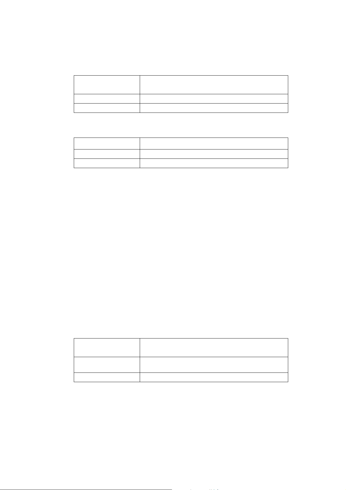
Z - Reset to Factory Defined Configuration
Action command syntax
Command Possible response(s)
Z
Description
This command resets the values to user default settings and closes all connections. If the TA
has a data-call in progress, it is disconnected from the call, terminating any (GSM) dataconnection in progress. GPRS connection isn’t affected by this command.
All of the functions of the command shall be completed before the TA issues the result code.
An OK result code for this command is issued using the same rate, parity, and word format
as the TE command line containing the command, but using the new values for parameters
that affect the format of result codes (e.g. Q, V, S3, S4).
Comments
ATZ is the same as ATH&F.
The TE should not include additional commands on the same command line after the Z
command because such commands may be ignored.
Because this command may take into consideration the settings of nonvolatile parameter
storage, it does not necessarily return the TA to a “known state”. In particular, the TA may,
as a result of execution of this command, be placed in a state in which it appears to not
respond to TE commands, or respond in a completely different format than was being used
prior to execution of the command.
Control and Identification Commands 23

&F - Reset to Default Configuration
Action command syntax
Command Possible response(s)
&F
Description
This command instructs the TA to set all parameters to factory default values specified by
the manufacturer, which may take into consideration hardware configuration switches and
other manufacturer-defined criteria.
Comments
An OK result code for this command is issued using the same rate, parity, and word format
as the TE command line containing the command, but using the factory-defined values for
other parameters that affect the format of result codes (e.g. Q, V, S3, S4) and dependent upon
other commands that may follow on the same command line.
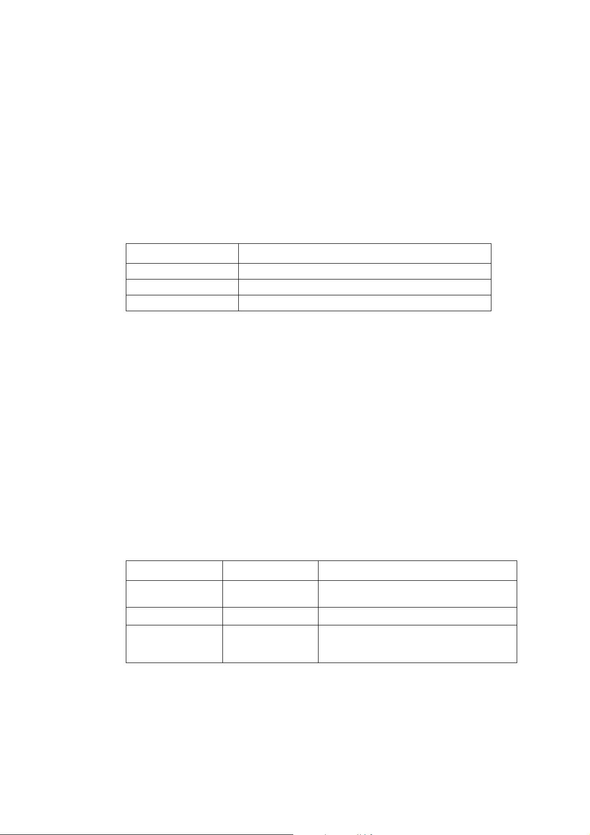
I - Request HW Version
Action command syntax Command
Command Possible response(s)
ATI<value> <information>
Description
This command causes the TA to transmit one or more lines of information text, determined
by the manufacturer.
Parameter-Values
<Value> <Information>
0 same info as +GMM
1 same info as +GMR.
8 TA hardware revision (Type approved HW revision).
Comments
Hardware revision must be stored so it does not change when the software is upgraded.
24 Control and Identification Commands

+CGMI (+GMI) - Request Manufacturer Identification
Action command syntax
Command
+CGMI SONYERICSSON
+CGMI=?
Possible response(s):
+CME ERROR: <err>
Action command syntax
Command Possible response(s)
+GMI SONYERICSSON
+GMI=?
Description
The +CGMI command is used to get the identity of the manufacturer of the phone (ME).
AT+GMI command is used to get the identity of the manufacturer of the modem (TA). The
+GMI command will never give an ERROR response.
Test command is used to determine if the command is supported.
Parameter-Values
<manufacturer> Sony Ericsson.
<err> “Error Messages”, page 227
Control and Identification Commands 25

+CGMM (+GMM) - Request Model Id
Action command syntax
Command
+CGMM <model-type><model-name>
+CGMM=?
Action command syntax
Command Possible response(s)
+GMM <model-name>
+GMM=?
Description
Possible response(s):
+CME ERROR: <err>
The +CGMM command is used to get the model of the phone (MS) determined by the
manufacturer.
The +GMM command is used to get the model of the modem (TA). The +GMM command
will never give an ERROR response.
Test command is used to determine if the command is supported.
Parameter-Values
<model-type> : “6130201-BV”: A unique ASCII character/digit that may include
blank characters. Always 10 characters long (padded with space if
less than 10 digits long).
<model-name> “GC7x/GC8x”: model name for the transceiver unit.
<err> Refer to “+CME ERROR: <err> - Mobile Equipment error result
code”, page 227.
26 Control and Identification Commands
+CGMR (+GMR) - Request Revision Id
Action command syntax
Command
+CGMR <revision>
+CGMR=?
Possible response(s):
+CME ERROR: <err>
Action command syntax
Command Possible response(s)
+GMR <revision>
+GMR=?
Description
The +CGMR command is used to get the SW version of the phone (ME).
The +GMR command is used to get the SW version of the modem (TA). The +GMR
command will never give an ERROR response.
Test command is used to determine if the command is supported.
Parameter-Values
<revision> An ASCII string containing a six digit date (year, month, day),
<space>, a four digit time (hour, minute), <space>,
<softwareidentity>.
<err> Refer to “+CME ERROR: <err> - Mobile Equipment error result
code”, page 227.
+CLAC - List All Available AT Commands
Action command syntax
Command
+CLAC <AT Command-1>
+CLAC=?
Description
Execution command causes the ME to return one or more lines of AT Commands.
Possible response(s):
+CME ERROR: <err>
[<CR><LF><AT Command-2>[...]]
Control and Identification Commands 27

Parameter-Values
<AT Command-n> Defines the AT command including the prefix AT. Text shall not
contain the sequence 0<CR> or OK<CR>
<err> Refer to “+CME ERROR: <err> - Mobile Equipment error result
code”, page 227.
Comments
This command only returns the AT commands that are available for the end user. This
command is equivalent to AT*.
* - List All AT Commands
Action command syntax
Command Possible response(s)
* <Command-1>
<CR><LF><Command-2>[...]]
Description
This command is used to get the list of the supported commands.
Parameter-Values
<Commandx> defines the AT Command. Text shall not contain the sequence
0<CR> or OK<CR>
Comments
This command only returns the AT commands that are available for the end user.
+GCAP - Request Modem Capability List
Action command syntax
Command Possible response(s)
+GCAP +GCAP: (list of supported <capability>s)
+GCAP=?
Description
This command is used to request the list of valid Modem Command Prefixes.
28 Control and Identification Commands
Parameter-Values
<capability> Description
+CGSM GSM commands
+FCLASS Facsimile 2 commands
+DS V42bis, compression
+ES V42, Error correction
+WS46 - select wireless network (PCCA STD-101)
Parameter command syntax
Command Possible response(s)
+WS46=[<n>]
+WS46? <n>
+WS46=? (list of supported <n>s)
Description
Set command to select the WDS side stack <n> to be used by the TA. Read command shows
current setting and test command displays side stacks implemented in the TA.
Defined values
<n>
0 Indicates that no wireless stack is active i.e +CFUN=4. Only possible in
a response.
12 GSM digital cellular i.e. +CFUN=1. Default.
240 Indicates that no wireless stack is active and the phone is connected to
a power source (charge only mode) i.e. +CFUN=0.
Only possible in a response.
*MCNFG - Module Configuration Change
Description Syntax Possible Responses
Activate command *MCNFG=<configTy
pe>, <mode>
Check command
Test if the command
is supported
*MCNFG
*MCNFG =? *MCNFG: (list of supported < configType
?
This command changes the default configuration of the module.
OK
+CME ERROR: <err>
+CME ERROR: <err>
>s,<mode>s)
+CME ERROR: <err>
Control and Identification Commands 29

<mode>
0 Disable functionality.
0 Enable functionality.
<configType>
1 Disable/Enable following unsolicited events using <mode> = 0 or
1.Incoming SMS event.SMS memory full eventPhonebook ready event
(at power-up)
2 Disable/Enable SMS read status change from REC_UNREAD to
REC_READ (at SMS read/list command +CMGR\+CMGL) using
<mode> = 0 or 1.
3 <mode> = 1 Set module into GSM only mode, after power up. No
GPRS attach will be performed.<mode> = 0 Set module into
GSM\GPRS mode as default.
4 <mode> = 1 PDA to inform the firmware that the SMS storage on the
PDA side is full.<mode> = 0 PDA to inform the firmware that the SMS
storage on the PDA side is available again. Default Setting
Note! Because the PDA set the SMS display mode to display only (AT+CNMI=2.2_ for SMS to be
sent to PDA directly without storing to SIM, PDA will need to reset the mode to default
value of AT+CNMI=2, 1 when PDA storage is full, so that the firmware can start to manage
the storage of incoming SMS in SIM.
*MCNFG=1, 1/0 and *MMGSR are a pair. When *MCNFG=2, 0 is issued, SMS status will
not be changed by +CMGR\+CMGL. The status must be changed by *MMGSR after the
user reads it. If *MCNFG=2, 1 is issued (this is also the default value), there is no need to
use *MMGSR.
<err>
0-255 For values refer to +CME ERROR tables.
30 Control and Identification Commands

*MRDY - Module Ready Status
*MRDY Unsolicited Result Code
Command Possible Responses
*MVMIND: <status>
This unsolicited command is sent to the TE when various status events occur after the
GSM\GPRS module is powered up.
<status>
1 Module is ready.
2 112 emergency call is ready.
3 All AT commands are ready.
4 SIM card removed.
5 SIM card inserted.
6 No Access - limited service
7 SOS - limited service (Unrecoverable, need to power cycle to get back
to normal service).
+CCLK - Set Real Time Clock
Description Syntax Possible Responses
Activate command +CCLK =<time> +CME ERROR: <err>
Check command +CCLK? +CCLK: <time>
+CME ERROR: <err>
Test if the command
is supported
This command is used to set the internal Real Time Clock of the MT. If the setting fails in
an MT error, +CME ERROR: then <err> is returned.
The Read Command returns the current setting of the clock.
<time>
String type format is "yy/MM/dd,hh:mm:ss±zz", where characters indicate year
+CCLK =? *MCNFG: (list of supported < configType
>s,<mode>s)
+CME ERROR: <err>
(two last digits), month, day, hour, minutes, seconds and time zone
(indicates the difference, expressed in quarters of an hour, between the
local time and GMT; range ?47...+48). E.g. 6th of May 1994, 22:10:00
GMT+2 hours equals to "94/05/06,22:10:00+08"NOTE:If MT does
not support time zone information then the three last characters of
<time> are not returned by +CCLK? The format of <time> is specified
by use of the +CSDF command.
Control and Identification Commands 31

<err>
0-255 For values refer to +CME ERROR tables.
32 Control and Identification Commands

Call Control
A - Answer
Action command syntax
Command Possible response(s)
A CONNECT
A=?
Unsolicited Result Codes
Description
CONNECT <text>
NO CARRIER
RING
+CRING
This command is used to signal the MS to answer an incoming data-call. The command is
followed by an intermediate result code such as CONNECT and enters Online State.
Any additional commands that appear after A on the same command line are ignored.
Parameter-Values
<text>
9600 9600 bps
14400 14400 bps
19200 19200 bps
28800 28800 bps
Abortability
The A command may be aborted in the manner described in “Aborting commands”, page 17.
If the TA is connected to the line, it disconnects from the line in an orderly manner as
required by the state of the connection. Aborting the connection by reception of a character
is generally possible at any time before the TA enters online data state, but may not be
possible during some states of connection establishment, such as handshaking. The TA shall
issue a final result code; which result code to issue shall be determined by the manufacturer,
and may depend upon the state of the connection at the time the character was received from
the TE. If a CONNECT or CONNECT <text> result code is received by the TE, this indicates
that the attempt to abort the command was not successful, possibly due to the state of
connection establishment at the time the character was sent.
Call Control 33

Comments
This command may only initiate a data-call setup, so an “OK” result code would indicate an
unsuccessful call-setup.
H - Hang up
Action command syntax
Command Possible response(s)
H[<value>]
Description
This command is used to signal the MS to terminate an active call. All of the functions of the
command shall be completed before the TA issues any result code.
Parameter-Values
<value>
0 Disconnect and terminate active data-call. Default.
D - Dial (non GPRS calls)
Execute command syntax
Command Possible response(s)
D<dial_string> CONNECT
CONNECT <text>
NO CARRIER
ERROR
BUSY
Description
This command is used to signal the MS to dial a call.
All characters appearing on the same command line after the “D” are considered part of the
call addressing information to be signalled to the network, or modifiers used to control the
signalling process (collectively known as a “dial string”), up to a semicolon character (IA5
3/11) or the end of the command line.
Any characters appearing in the dial string that the TA does not recognize as a valid part of
the call addressing information or as a valid modifier shall be ignored. This permits
characters such as parentheses and hyphens to be included that are typically used in
formatting of telephone numbers.
34 Call Control

V.25ter [28] dial command D lists characters that may be used in a dialling string for making
a call or controlling supplementary services in accordance with GSM 02.30 [3]. Their use in
GSM is listed in this subclause, as well as new dial modifiers applicable only to GSM are
introduced. For a ME supporting AT commands only, it is mandatory to support the control
of supplementary services in accordance with GSM 02.30 [3] through the dial command or
through the specific supplementary service commands (+CCFC, +CLCK, etc.), where GSM
02.30 [3] identifies the supplementary services as mandatory.
<Dial-string> Parameter
V.25ter [28] dialling digits
1 2 3 4 5 6 7 8 9 0 * # + A B C (implementation of these characters is mandatory for GSM)
“+” When given before dialing digits the call is originated to an
international ISDN address (TON/NPI = 145) else the call is originated
to an un-known type of ISDN address (TON/NPI = 169)
V.25ter [28] modifier characters
, (implementation of this character is mandatory for GSM, but it is
ignored)
T P (implementation of these characters is mandatory for GSM, but they are
ignored)
V.25ter [28] semicolon character
; In GSM, when semicolon character is given after dialling digits (and
modifiers), a voice call is originated to the given address. The PC Card
will issue an ERROR response when this dial modifier is found in the
dial-string.
GSM modifier characters
> (refer subclause “Direct dialling from phonebooks”)
I or i (override the CLIR supplementary service subscription default value
for this call; I = invocation (restrict CLI presentation) and i =
suppression (allow CLI presentation); refer subclause “+CLIR - Calling
line identification restriction”)
Possible responses to ATD command are following:
• CONNECT if a data-call is successfully established.
• NO CARRIER if unable to establish a connection or if the Mobile phone is not registered or if
the connection attempt was aborted by the user.
• ERROR if ATD is unsuccessfully executed by the MS.
• NO DIALTONE if the mobile is not within coverage of the network.
• BUSY if the phone number called is engaged.
Call Control 35

• DELAYED if calling attempt is delayed because of repeat restrictions, this is an intermediate
result code.
• BLACKLISTED when modem is blocked because of repeat restrictions.
Comments
Note! Command also supports Supplementary Service Code (SSC) strings, e.g.
ATD**61*<adr>*11*25# (See GSM 07.07 [18] §6.23)
This subclause describes how existing AT commands, designed for use with a modem, may
be used to control a GPRS MO and GPRS MT connection. This is to provide backwards
compatibility with existing communications software. For new applications it is
recommended that the GPRS-specific commands be used.
MT originated PDP context activation
In this mode of operation, the MT behaves like an originating modem and accepts the normal
V.25ter commands associated with placing and clearing a call. If GPRS-specific
configuration commands are required, they may be sent to the MT as part of the modem
initialisation commands.
D*99* - Request GPRS service
Execute command syntax
Command Possible response(s)
D*99[*[<called_address>]
[*[<L2P>][*[<cid>]]]]#
Description
This command causes the CG75 to perform whatever actions are necessary to establish
communication between the TE and the external PDN. The V.25ter 'D' (Dial) command
causes the MT to enter the V.25ter online data state and, with the TE, to start the specified
layer 2 protocol. The MT returns CONNECT to confirm acceptance of the command prior
to entering the V.25ter online data state. No further commands may follow on the AT
command line.
The detailed behaviour after the online data state has been entered is dependent on the PDP
type. It is described briefly in clauses 8 (for X.25) and 9 (for IP) of GSM 07.60. GPRS
attachment and PDP context activation procedures may take place prior to or during the PDP
start-up if they have not already been performed using the +CGATT and +CGACT
commands.
CONNECT
CONNECT <text>
ERROR
36 Call Control

When the layer 2 protocol has terminated, either as a result of an orderly shut down of the
PDP or an error, the MT enters V.25ter command state and returns the NO CARRIER final
result code.
If <called address> is supported and provided, the MT shall automatically set up a virtual call
to the specified address after the PDP context has been activated.
If <L2P> and <cid> are supported, their usage shall be the same as in the +CGDATA
command. The +CGDCONT, +CGQREQ, etc. commands may then be used in the modem
initialisation AT command string to set values for PDP type, APN, QoS etc.
If <L2P> is not supported or is supported but omitted, the MT shall use a layer 2 protocol
appropriate to the PDP type.
If <cid> is not supported or is supported but omitted, the MT shall attempt to activate the
context using:
(a) any information provided by the TE during the PDP start-up procedure,
e.g. the TE may provide a PDP type and/or PDP address to the MT, or
(b) a prior knowledge, e.g. the MT may implement only one PDP type, or
(c) using the 'Empty PDP type' (GSM 04.08). (No PDP address or APN
shall be sent in this case and only one PDP context subscription record
shall be present in the HLR for this subscriber.)
This command may be used in both normal and modem compatibility modes.
Note! The dial string conforms to the syntax specified in GSM 02.30.
Parameter-Values
<value> Description
<called_address> a string that identifies the called party in the address, equivalent may
be used. Also, the character comma ',' may be used as a substitute for
the character period '.'.
<L2P> a string which indicates the layer 2 protocol to be used (see
+CGDATA command). For communications software that does not
support arbitrary characters in the dial string, the following numeric
equivalents shall be used:
0 NULL (Obsolete)
1 PPP
2 PAD
3 X25
9yyyy M-xxxx
Other values are reserved and will result in an ERROR response to
the set command.
Note! V.250 (and certain communications software) does not permit arbitrary characters in the
dial string. The <L2P> and <called_address> strings are therefore specified as containing
digits (0-9) only.
Call Control 37

<cid> a digit string which specifies a particular PDP context definition (see
+CGDCONT command).
D*98* - Request GPRS IP service
Execute command syntax
Command Possible response(s)
D*98[*<cid>]# CONNECT
CONNECT <text>
ERROR
Description
This command causes the MT to perform whatever actions are necessary to establish
communication between the TE and the external PDN.
The V.25ter 'D' (Dial) command causes the MT to enter the V.25ter online data state and,
with the TE, to start the specified layer 2 protocol. The MT shall return CONNECT to
confirm acceptance of the command prior to entering the V.25ter online data state. No further
commands may follow on the AT command line.
The detailed behaviour after the online data state has been entered is described briefly in
clause 9, for IP, of GSM 07.60. GPRS attachment and PDP context activation procedures
may take place prior to or during the PDP start-up if they have not already been performed
using the +CGATT and +CGACT commands.
When the layer 2 protocol has terminated, either as a result of an orderly shut down of the
PDP or an error, the MT shall enter V.25ter command state and return the NO CARRIER
final result code.
If <cid> is supported, its usage shall be the same as in the +CGDATA command. The
+CGDCONT, +CGQREQ, etc. commands may then be used in the modem initialisation AT
command string to set values for PDP type, APN, QoS etc.
If <cid> is not supported or is supported but omitted, the MT shall attempt to activate the
context using:
(a) any information provided by the TE during the PDP start-up procedure,
e.g. the TE may provide a PDP type and/or PDP address to the MT, or
(b) a prior knowledge, e.g. the MT may implement only one PDP type, or
(c) using the 'Empty PDP type' (GSM 04.08). (No PDP address or APN
shall be sent in this case and only one PDP context subscription record
shall be present in the HLR for this subscriber.)
This command may be used in both normal and modem compatibility modes.
Note! The dial string conforms to the syntax specified in GSM 02.30.
38 Call Control

Defined Values
<value> Description
<GPRS_SC_IP> (GPRS Service Code for IP) a digit string (value 98) which identifies
a request to use the GPRS with IP (PDP types IP and PPP)
<cid> a digit string which specifies a particular PDP context definition(see
+CGDCONT command).
Network requested PDP context activation
In this mode of operation, the MT behaves like an answering modem and accepts the normal
V.25ter commands associated with answering a call. If GPRS-specific configuration
commands are required, they may be sent to the PC Card as part of the modem initialisation
commands.
The +CGAUTO command is used to select modem compatibility mode.
S0 - Automatic response to a network request for PDP context
activation
Description
The V.25ter 'S0=n' (Automatic answer) command may be used to turn off (n=0) and on (n>0)
the automatic response to a network request for a PDP context activation.
When the 'S0=n' (n>0) command is received, the PC Card will attempt to perform a GPRS
attach if it is not already attached. Failure will result in ERROR being returned to the TE.
Subsequently, the PC Card will announce a network request for PDP context activation by
issuing the unsolicited result code RING to the TE, followed by the intermediate result code
CONNECT. The PC Card then enters V.25ter online data state and follows the same
procedure as it would after having received a +CGANS=1 with no <L2P> or <cid> values
specified.
Note! The 'S0=n' (n=0) command does not perform an automatic GPRS detach.
A - Manual acceptance of a network request for PDP context activation
Description
The V.25ter 'A' (Answer) command may be used to accept a network request for a PDP
context activation announced by the unsolicited result code RING. The PC Card responds
with CONNECT, enters V.25ter online data state and follows the same procedure as it would
after having received a +CGANS=1 with no <L2P> or <cid> values specified. It is an error
to issue the 'A' command when there is no outstanding network request.
Call Control 39

H - Manual rejection of a network request for PDP context activation
Description
The V.25ter 'H' or 'H0' (On-hook) command may be used to reject a network request for PDP
context activation announced by the unsolicited result code RING. The PC Card responds
with OK. It is an error to issue the 'H' command when there is no outstanding network
request.
Note! This is an extension to the usage of the 'H' command that is described in ITU-T V.25ter.
L - Monitor Speaker Loudness
Parameter command syntax
Command Possible response(s)
L[<value>]
L? L: <value>
L=? L: (list of supported <value>s)
Description
This command is ignored
Read command is used to show the current setting
Test command is used to show the list of the supported values for monitor speaker.
Parameter-Values
<value> Description
0 Min speaker volume (Silent). Default.
1-255 OK but ignored
40 Call Control

+CFUN - Set Phone Functionality
Parameter command syntax
Command Possible response(s)
+CME ERROR: <err>
+CFUN=[<fun>[,<rst>]]
+CFUN? +CFUN: <fun>
+CFUN=? +CFUN: (list of supported <fun>s), (list of supported
<rst>s)
Description
Set command +CFUN is used to set the MS functionality and to select the level of the
functionality.
Read command is used to show the current setting.
Test command is used to show the list of the supported power levels and supported reset
modes, as compound values.
Parameter-Values
<fun> Description
0 Minimum functionality. Default.
1 Full functionality.
4 Disable MS transmit and receive RF circuits.
<rst> Description
0 Do not reset. Default.
1 Reset the MS before setting it to <fun> power level .
<err> Refer to “+CME ERROR: <err> - Mobile Equipment error result
code”, page 227.
Comments
The only commands available when +CFUN=0 are; +CFUN, +GMI, +CGMI, +GMM,
+CGMM, +GMR, +CGMR and +CGSN.
Call Control 41

RING - Ring Indication
Unsolicited result code
Command Possible response(s)
RING
Description
This result code is issued by the MS to report an incoming call. This result code should be
repeated each time the network repeats the incoming call indication.
The transmitting of RING result codes from the MS to the TE may be suppressed during
command entry and execution. Circuit 125, if provided, may be unaffected by the status of
command entry and execution and continue to indicate incoming calls even though
transmitting of RING result codes is suppressed.
Comments
See “+CRC - Cellular Result Code”, page 102.
O - Return to On-line Data Mode
Execution command syntax
Command Possible response(s)
O[=][<action>] ERROR
CONNECT
CONNECT <text>
NO CARRIER
O=?
Description
Returns the PC Card to on-line data mode from on-line command mode.
Parameter-Values
<action>
0 (default) switch from on-line command to on-line data state.
Comments
Possible responses
ERROR <action> is outside legal range or not in on-line command mode.
CONNECT Re-established data connection.
42 Call Control

NO CARRIER data connection lost or aborted by user.
P - Select Pulse Dialing
Parameter command syntax
Command Possible response(s)
P
P=?
Description
This command is ignored and implemented for compatibility only. It would normally cause
the next D command (see “D - Dial (non GPRS calls)”, page 34) to use pulses when dialing
the number.
T - Select Tone Dialing
Parameter command syntax
Command Possible response(s)
T
T=?
Description
This command is ignored and implemented for compatibility only. It would normally cause
the next D command (see “D - Dial (non GPRS calls)”, page 34) to use tones when dialing
the number.
Call Control 43

+CAOC - Advice of Charge
Action/Parameter command syntax
Command Possible response(s)
+CME ERROR <err>
+CAOC[=<mode>] [+CAOC: <ccm>]
+CAOC? +CAOC: <mode>
+CAOC=? [+CAOC: (list of supported <mode>s]
Unsolicited Result Code
+CAOC: <ccm>
Description
This refers to Advice of Charge supplementary service (GSM 02.24 [2] and GSM 02.86 [16])
that enables subscriber to get information about the cost of calls. With <mode>=0, the
execute command returns the current call meter value from the ME.
The command also includes the possibility to enable an unsolicited event reporting of the
CCM information. The unsolicited result code +CCCM is sent when the CCM value
changes, but not more that every 10 seconds. Deactivation of the unsolicited event reporting
is made with the same command.
Read command indicates whether the unsolicited reporting is activated or not.
Test command returns the supported mode values.
Parameter-Values
<mode>
0 query CCM value
1 deactivate the unsolicited reporting of CCM value
2 activate the unsolicited reporting of CCM value
<ccm> string type; three bytes of the current call meter value in hexadecimal
format (e.g. “00001E” indicates decimal value 30); value is in home
units and bytes are similarly coded as ACMmax value in the SIM.
<err> Refer to “+CME ERROR: <err> - Mobile Equipment error result
code”, page 227.
Comments
Also see
“+CACM - Accumulated Call Meter”, page 45;
“+CAMM - Accumulated Call Meter Maximum”, page 46;
44 Call Control

“+CPUC - Price per unit and currency”, page 47;
“+CCWE - Call Meter Maximum Event”, page 48.
+CACM - Accumulated Call Meter
Parameter command syntax
Command Possible response(s)
+CME ERROR <err>
+CACM=[<passwd>]
+CACM? +CACM: <acm>
+CACM=?
Description
Set command resets the Advice of Charge related accumulated call meter value in SIM file
EF_ACM. ACM contains the total number of home units for both the current and preceding
calls. SIM PIN2 is usually required to reset the value. If setting fails in a +CME ERROR is
returned.
Read command returns the current value of ACM.
Parameter-Values
<passwd> string type; SIM PIN2
<acm> string type; accumulated call meter value similarly coded as <ccm>
under +CAOC
<err> Refer to “+CME ERROR: <err> - Mobile Equipment error result
code”, page 227.
Comments
Also see
“+CAOC - Advice of Charge”, page 44;
“+CAMM - Accumulated Call Meter Maximum”, page 46;
“+CPUC - Price per unit and currency”, page 47;
“+CCWE - Call Meter Maximum Event”, page 48.
Call Control 45

+CAMM - Accumulated Call Meter Maximum
Parameter command syntax
Command Possible response(s)
+CME ERROR <err>
+CAMM=[<acmmax>[,<passwd>]]
+CAMM? +CAMM: <acmmax>
+CAMM=?
Description
Set command sets the Advice of Charge related accumulated call meter maximum value in
SIM file EF_ACMmax. ACMmax contains the maximum number of home units, allowed to
be consumed, by the subscriber. When ACM (refer to “+CACM - Accumulated Call Meter”,
page 45) reaches ACMmax, calls are prohibited (see also GSM 02.24 [2]). SIM PIN2 is
usually required to set the value. If setting fails an +CME ERROR is returned.
Read command returns the current value of ACMmax
Parameter-Values
<acmmax> string type; accumulated call meter maximum value similarly coded
as <ccm> under “+CAOC - Advice of Charge”, page 44; value zero
disables ACMmax feature
<passwd> string type; SIM PIN2
<err> Refer to “+CME ERROR: <err> - Mobile Equipment error result
code”, page 227
Comments
Also see:
“+CAOC - Advice of Charge”, page 44;
“+CACM - Accumulated Call Meter”, page 45;
“+CPUC - Price per unit and currency”, page 47;
“+CCWE - Call Meter Maximum Event”, page 48.
46 Call Control

+CPUC - Price per unit and currency
Parameter command syntax
Command Possible response(s)
+CME ERROR <err>
+CPUC=<currency>,<ppu>[,<passwd>]
+CPUC? +CPUC: <currency>,<ppu>
+CPUC=?
Description
Set command sets the parameters of Advice of Charge related price per unit and currency
table in SIM file EF_PUCT. PUCT information can be used to convert the home units (as
used in +CAOC, +CACM and +CAMM) into currency units. SIM PIN2 is usually required
to set the parameters.
Read command returns the current parameters of PUCT.
Parameter-Values
<currency> string type; three-character currency code (e.g. .GBP., .DEM.);
character set as specified by command Select TE Character Set
+CSCS
<ppu> string type; price per unit; dot is used as a decimal separator
(e.g. .2.66.)
<passwd> string type; SIM PIN2
<err> Refer to “+CME ERROR: <err> - Mobile Equipment error result
code”, page 227
Comments
Also see:
“+CAOC - Advice of Charge”, page 44;
“+CACM - Accumulated Call Meter”, page 45;
“+CAMM - Accumulated Call Meter Maximum”, page 46;
“+CCWE - Call Meter Maximum Event”, page 48.
Call Control 47

+CCWE - Call Meter Maximum Event
Parameter command syntax
Command Possible response(s)
+CME ERROR <err>
+CCWE=<mode>
+CCWE? +CCWE: <mode>
+CCWE=? +CCWE: (list of supported <mode>s)
Unsolicited Result Code
+CCWV
Description
Shortly before the ACM (Accumulated Call Meter) maximum value is reached, an
unsolicited result code +CCWV will be sent, if enabled by this command.
The warning is issued approximately when 30 seconds call time remains. It is also issued
when starting a call if less than 30 s call time remains. If setting fails in an +CME ERROR
is returned.
Read command returns the current setting.
Test command returns supported settings.
Parameter-Values
<mode> Description
0 (default) Disable the call meter warning event
1 Enable the call meter warning event
<err> Refer to “+CME ERROR: <err> - Mobile Equipment error result
code”, page 227
Comments
Also see:
“+CAOC - Advice of Charge”, page 44;
“+CACM - Accumulated Call Meter”, page 45;
“+CAMM - Accumulated Call Meter Maximum”, page 46;
“+CPUC - Price per unit and currency”, page 47.
48 Call Control

+CPWC - Power class
Parameter command syntax
Command Possible response(s)
+CME ERROR <err>
+CPWC=[<class>[,<band>]]
+CPWC? +CPWC: <curr_class1>,<def_class1>,<band1>
[,<curr_class2>,<def_class2>,<band2>[...]]
+CPWC=? +CPWC: list of supported (<band>, (list of
<class>s)) pairs
Description
This command is used to set the preferred ME power class for each GSM frequency band
supported. If setting fails +CME ERROR is returned.
Read command returns the currently selected output power class and default output power
class for each supported frequency band. Parameter <band1> and its associated power class
parameters refer to the currently used frequency band. For example, +CPWC: 2,1,1,5,4,0 in
case of a dual-band ME currently using band GSM1800, for which the power class is
currently set to 2, the default being class 1, and for which the currently set power class value
for GSM900 is class 5 the default being class 4.
Test command returns supported bands and their power classes. For example, +CPWC:
(0,(0,4,5)),(1,(0-2)) in case of a dual-band hand-held ME.
Parameter-Values
<class>
<curr_classn>s
<def_classn>s
0 default (not applicable to <curr_class>s or <def_classn>s)
1 MS output power class as in GSM 05.05 [15]
<band>
<bandn>s
0 GSM900. Default.
1 GSM1800
2 GSM1900
<err> Refer to “+CME ERROR: <err> - Mobile Equipment error result
code”, page 227
Call Control 49

+CPAS - Phone Activity Status
Action command syntax
Command Possible response(s)
+CME ERROR <err>
+CPAS +CPAS: <pas>
+CPAS=? +CPAS: (list of supported <pas>s)
Description
Execution command returns the activity status <pas> of the ME. It can be used to interrogate
the ME before requesting action from the phone.
Test command returns values supported by the ME as a compound value.
Parameter-Values
<pas>
0 Ready (ME allows commands from TA/TE).
3 Ringing (ME is ready for commands from TA/TE, but the ringer is
active).
4 Call in progress (ME is ready for commands from TA/TE, but a call
is in progress).
<err> Refer to “+CME ERROR: <err> - Mobile Equipment error result
code”, page 227
+CSTA - Select Type of Address
Parameter command syntax
Command Possible response(s)
+CSTA=[<type>]
+CSTA? +CSTA: <type>
+CSTA=? +CSTA: (list of supported <type>s)
Description
Set command selects the type of number for further dialing commands (D) according to GSM
specifications.
Test command returns values supported by the TA as a compound value.
50 Call Control

Parameter-Values
<type> type of address octet in integer format (refer GSM 04.08 [13] sub
clause 10.5.4.7); default 145 when dialing string includes
international access code character “+”, otherwise 129
+CHUP - Hangup Call
Description Syntax Possible Responses
Activate command AT+CHUP
Interrogate
command
AT+CHUP=?
Execution command causes the TA to hang-up the current GSM/UMTS call of the MT.
Note! The purpose of this command is not to replace the V.250 [14] command H, but to give an
assured procedure to terminate an alternating mode call
+CKPD - Keypad Control
Description Command Possible Responses
Select ME controls AT+CKPD=[<keys>[,
<time>[, <pause>]]
Test if the command
is supported
AT+CKPD= ? OK
+CME ERROR: <err>
OK
ERROR
Execution command emulates MT keypad by giving each keystroke as a character in a string
<keys>. <time>*0.1 seconds is the time to stroke each key and <pause>*0.1 seconds is the
length of pause between two strokes. If emulating fails in an MT error, +CME ERROR:
<err> is returned. Refer sub clause 9.2 for <err> values. This command should be accepted
(OK returned) before actually starting to press the keys. Thus unsolicited result codes of key
pressings and display events can be returned.
Defined values:
<keys> string of characters representing keys as listed in the following table. Colon
character (IRA 58) followed by one character can be used to indicate a manufacturer specific
key not listed here. All characters from a semicolon character (IRA 59) to the next single
semicolon character are treated as alpha entries and are not converted to key equivalents. All
semicolon characters inside alpha entries should be duplicated in the TE and stripped to one
before entering to the MT. Pause character (IRA 87 or 119) can be used to pause between
key pressings for a time specified by <pause>. All IRA values not listed here are reserved.
Char IRA (decimal) Comment (+some known key symbols)
# 35 Hash (number sign).
% 37 Percent sign.
Call Control 51

Char IRA (decimal) Comment (+some known key symbols)
* 42 star (*)
0.... 9 48... 57 number keys
: 58 escape character for manufacturer specific keys
; 59: escape character for string entering
<60 left arrow
> 62 right arrow
@ 64 alpha key (?/ABC)
A/a 65/97 channel A (A)
B/b 66/98 channel B (B)
C/c 67/99 clear display (C/CLR)
D/d 68/100 volume down
E/e 69/101 connection end (END
F/f 70/102 function (FCN)
L/l 76/108 phone lock (LOCK)
M/m 77/109 menu (MENU)
P/p 80/112 power (PWR)
Q/q 81/113 quiet/mute (MUTE)
R/r 82/114 recall last number (R/RCL/MR)
S/s 83/115 connection start (SEND)
T/t 84/116 store/ memory (STO/M/M+)
U/u 85/117 volume up
V/v 86/118 down arrow
W/w 87/119 pause character
X/x 88/120 auxiliary (AUX)
Y/y 89/121 delete last character (C)
[ 91 soft key 1
] 93 soft key 2
^ 94 up arrow
<time>, <pause>
0-25 5 seconds (default values are manufacturer specific, but should be so
<err>
0-255 For values refer to +CME ERROR tables.
52 Call Control
long that a normal MT can handle keystrokes correctly)

+CSIM - Generic SIM Access
Description Syntax Possible Responses
Activate command +CSIM=<length>,<comm
and>
Interrogate
command
+CSIM=?
+CSIM: <length>,<response>
+CME ERROR: <err>
Set command transmits to the MT the <command> it then shall send as it is to the SIM. In
the same manner the SIM <response> shall be sent back by the MT to the TA as it is.
This command allows a direct control of the SIM by an distant application on the TE. The
TE shall then take care of processing SIM information within the frame specified by GSM/
UMTS.
The AT+CSIM command is implemented to support only the RUN GSM ALGORITHM as
specified in GSM 11.11 and duplicated here for convenience.
Attempting any other GSM 11.11 SIM operation will reset the SIM.
Note! Compared to Restricted SIM Access command +CRSM, the definition of +CSIM allows TE
to take more control over the SIM?MT interface. The locking and unlocking of the interface
may be done by a special <command> value or automatically by TA/MT (by interpreting
<command> parameter). In case that TE application does not use the unlock command (or
does not send a <command> causing automatic unlock) in a certain timeout value, MT may
release the locking.
<length>
Integer type Length of the characters that are sent to TE in <command> or
<response> (two times the actual length of the command or response).
<command >
Integer type Command passed on by the MT to the SIM in the format as described
in GSM 51.011 [28] (hexadecimal character format; refer +CSCS).
<response >
Integer type Response to the command passed on by the SIM to the MT in the format
as described in GSM 51.011 [28] (hexadecimal character format; refer
+CSCS).
Run GSM Algorithm
This function is used during the procedure for authenticating the SIM to a GSM network and
to calculate a cipher key. The card runs the specified algorithms A3 and A8 using a 16 byte
random number and the subscriber authentication key Ki, which is stored in the SIM. The
function returns the calculated response SRES and the cipher key Kc.
Call Control 53

The function shall not be executable unless DFGSM or any sub-directory under DFGSM has
been selected as the Current Directory and a successful CHV1 verification procedure has
been performed.
Input: RAND.
Output: SRES, Kc.
The contents of Kc shall be presented to algorithm A5 by the ME in its full 64 bit format as
delivered by the SIM.
Procedure:
1. Send command:
AT+CSIM=42,"A088000001XXXXXXXXXXXXXXXXXXXXXXXXXXXXXXXX
"<enter> where, XXXXXXXXXXXXXXXXXXXXXXXXXXXXXXXX = 16 bytes of
RANDOM data (32 characters).
2. Receive response: +CSIM: 4,"9FXX" where, XX is the length of the response to be used
in the get response command.
Get Response:
3. Send command: AT+CSIM=10,"A0C00000XX" <enter> where, XX is the value from
the response above.
4. 4) Receive response: +CSIM: n+4,"XXXXXXXXXXXXXXXXXXXXXXXX9000"
where, XXXXXXXXXXXXXXXXXXXXXXXX is the encrypted value of the GSM
ALGORITHM (24 characters) and 9000 indicates a completed command.
+CMUT - Mute Control
Description Syntax Possible Responses
Activate command AT+CMUT=<n> +CME ERROR: <err>
Check command AT+CMUT? +CMUT: <n>+CME ERROR: <err>
Test if the command
is supported
This command is used to enable and disable the uplink voice muting during a voice call.
Test command returns supported values as compound value.
<n >
0 Mute off.
1 Mute on.
AT+CMUT =? +CMUT: (list of supported < n>s)
<err>
0-255 For values refer to +CME ERROR tables.
54 Call Control

+VTD - Tone Duration
Description Syntax Possible Responses
Activate command AT+VTD=<n>
Read command AT+VTD? <n>
Interrogate
command
AT+VTD=? (list of supported <n>s)
This command is used to set the duration of the tone (in tenths of seconds) that is set using
the AT+VTS command
<n>
Integer type A value different than zero causes a tone of duration <n>/10 seconds.
The value zero causes a "manufacturer specific" value.
Note! In GSM/UMTS the value of tone duration is preset and cannot be altered.
+VTS - DTMF and Tone Generation
Description Syntax Possible Responses
Activate command AT+VTS=as below
Interrogate
command
AT+VTS=? (list of supported <tone1>s), (list of
supported <tone2>s), (list of supported
<duration>s)
This command allows the transmission of DTMF tones and arbitrary tones (see note). These
tones may be used (for example) when announcing the start of a recording period. The
command is write only. In this profile of commands, this command does not operate in data
or fax modes of operation (+FCLASS=0,1,2?7).
Note! D is used only for dialling.
The string parameter of the command consists of combinations of the following separated
by commas:
1. <DTMF>. A single ASCII character in the set 0?9, #,*,A?D. This is interpreted as a
single ACSII character whose duration is set by the +VTD command.
Note! In GSM this operates only in voice mode.
2. [<tone1>,<tone2>,<duration>]. This is interpreted as a dual tone of frequencies
<tone1> and <tone2>, lasting for a time <duration> (in 10 ms multiples).
Note! This does not operate in GSM.
3. {<DTMF>,<duration>}. This is interpreted as a DTMF tone of different duration from
that mandated by the +VTD command.
Note! In GSM this operates only in voice mode.
Call Control 55

*MTRSH - Refresh Command
Description Syntax Possible Responses
Activate command RefreshType =
4:AT*MTRSH=
<RefreshType>else:AT*M
TRSH=
<RefreshType><CR>
<EF_List>
OK
ERROR
The REFRESH command contains the refresh type and the list of EF files (separated by
comma), if any.
In the case the refresh type is not SIM RESET, EF list will be given and cached data in the
firmware will be updated. PDA will need to update any cached data in PDA and response
with Terminal Response to inform the SIM if the command is carried out successfully. If the
response is not result=0 or 3, same command will be send again.
In the case the refresh type is SIM RESET, PDA will need to response if the reset can be
carried out (result=0) or currently unable to process the reset (result=20). If the response is
result=0, the firmware will be reset, and PDA will need to turn radio back on again. To save
unsaved data, PDA shall perform such task before response back to firmware using Terminal
Response. If the response result=20, the firmware will resend the command again at a later
time.
<RefreshType>
0 Initialise with full file change.
1 File Change.
2 Initialise with file change.
4 SIM reset.
<EF_list>
1 ACMMAX
2ADN
3FDN
4LND
5 MSISDN
6 PHASE
7PUCT
8SMS
9SMSP
10 SMSS
11 SST
12 IMSI
56 Call Control

13 ACC
14 BCCH
15 FPLMN
16 HPLMN
17 Kc
18 LOCI
19 PLMNsel
20 GPRS-Kc
21 GPRS-LOCI
22 CPHS-CSP
23 CINGULAR-ACTING-PLMN
99 No EF have changed
*MTRSH - Refresh Unsolicited Response
An unsolicited result code will present Refresh information. The *MTRSH unsolicited result
code has the following format.
*MTRES: 10, <Result1>[,<Result2>]
<Result1>
0 Command performed successfully.
3 Refresh performed with additional EF files read.
20 ME currently unable to process command (require <Result2>)
<Result2>
1 ME Screen busy.
2 ME Currently busy on call.
Call Control 57

Interface Commands
+++AT - Escape Sequence Character
Action command syntax
Command Possible response(s)
+++AT[<cmd>]<cr>
Description
This command is used for switching from on-line data mode to on-line command mode.
Parameter-Values
<cmd>
H[0] Hook Control, “Hang-up” (“H - Hang up”, page 34).
S3 - Command Line Termination Character
Parameter command syntax
Command Possible response(s)
S3=[<value>]
S3? <value>
S3=? S3: (list of supported <value>s)
Description
This S-parameter represents the decimal IA5 value of the character recognized by the TA
from the TE to terminate an incoming command line. It is also generated by the TA as part
of the header, trailer, and terminator for result codes and information text, along with the S4
parameter (see the description of the V parameter for usage).
The previous value of S3 is used to determine the command line termination character for
entry of the command line containing the S3 setting command. However, the result code
issued shall use the value of S3 as set during the processing of the command line. For
example, if S3 was previously set to 13 and the command line “ATS3=30” is issued, the
command line shall be terminated with a CR character (IA5 0/13), but the result code issued
will use the character with the ordinal value 30 (IA5 2/14) in place of the CR.
Read command is used to show the current setting.
Test command is used to show the list of the supported <value>s.
58 Interface Commands

Parameter-Values
<value>
13 Default command line termination character
0-127 other values, not supported
S4 - Response Formatting Character
Parameter command syntax
Command Possible response(s)
S4=[<value>]
S4? <value>
S4=? S4: (list of supported <value>s)
Description
This S-parameter represents the decimal IA5 value of the character generated by the TA as
part of the header, trailer, and terminator for result codes and information text, along with the
S3 parameter (see the description of the V parameter for usage (“V - TA Response Format”,
page 61)). If the value of S4 is changed in a command line, the result code issued in response
to that command line will use the new value of S4.
Read command is a command that is used to show the current setting.
Test command is used to show the list of the supported <value>s.
Parameter-Values
<value>
10 formatting character, default value
0-127 other values, not supported
Interface Commands 59

S5 - Command Line Editing Character
Parameter command syntax
Command Possible response(s)
S5=[<value>]
S5? <value>
S5=? S5: (list of supported <value>s)
Description
This S-parameter represents the decimal IA5 value of the character recognized by the TA as
a request to delete from the command line the immediately preceding character
(see“Command line editing”, page 10).
Read command is used to show the current setting.
Test command is used to show the list of the supported <value>s.
Parameter-Values
<value>
8 line editing character, default value
0-127 other values, not supported
E - Command Echo
Parameter command syntax
Command Possible response(s)
E[<value>]
E? <value>
E=? E=? (list of supported <value>s)
Description
The setting of this parameter determines whether or not the TA echoes characters received
from the TE during command state and online command state (see “Command line echo”,
page 10).
Read command is used to show the current setting.
Test command is used to show the list of the supported <value>s.
Parameter-Values
<value>
60 Interface Commands

0 TA does not echo characters during command state and online
command state
1 TA echoes characters during command state and online command
state, default value
Q - Result Code Suppression
Parameter command syntax
Command Possible response(s)
Q[<value>]
Q? <value>
Q=? (list of supported <value>s)
Description
The setting of this parameter determines whether or not the TA transmits result codes to the
TE. When result codes are being suppressed, no portion of any intermediate, final, or
unsolicited result code “header, result text, line terminator, or trailer” is transmitted.
Information text transmitted in response to commands is not affected by the setting of this
parameter.
Read command is used to show the current setting.
Test command is used to show the list of the supported <value>s.
Parameter-Values
<value>
0 TA transmits result codes, default value.
1 Result codes are suppressed and not transmitted.
V - TA Response Format
Parameter command syntax
Command Possible response(s)
V[<value>]
V? <value>
V=? (list of supported <value>s)
Description
This command is used to Request TA Response Format.
Interface Commands 61

The setting of this parameter determines the contents of the header and trailer transmitted
with result codes and information responses. It also determines whether result codes are
transmitted in a numeric form or an alphabetic (or “verbose”) form. The text portion of
information responses is not affected by this setting.
Table 3 shows the effect of the setting of this parameter on the format of information text and
result codes. All references to <CR> mean “the character with the ordinal value specified in
parameter S3”; all references to <LF> likewise mean “the character with the ordinal value
specified in parameter S4”.
Effect of V parameter on response formats
Table 3/V.25 ter V0 V1
Information responses <text><cr><lf> <cr><lf>
<text><cr><lf>
Result Codes <numeric code><cr> <cr><lf>
<verbose code><cr><lf>
Read command is used to show the current setting.
Test command is used to show the list of the supported <value>s.
Parameter-Values
<value>
0 TA transmits limited headers, trailers and numeric text.
1 TA transmits full headers, trailers and verbose response text.
Default.
Comments
TA Responses are described in “TA responses”, page 18.
&C - Circuit 109 (DCD) Control
Parameter command syntax
Command Possible response(s)
&C[<value>]
Description
This parameter determines how the state of DCD (circuit 109) relates to the detection of
received line state/signal from the distant end. Changing the parameter will take effect
immediately in both the command and online command states.
62 Interface Commands

Parameter-Values
<value>
0 DCD always on. Default.
Comments
For compatibility reasons only.
&D - Circuit 108 (DTR) Response
Parameter command syntax
Command Possible response(s)
&D[=][<value>]
Description
This command controls all action initiated by data terminal ready (DTR) from TE.
This parameter determines how the TA responds when DTR (circuit 108/2) is changed from
the ON to the OFF condition during online data state.
Parameter-Values
<value>
0 Ignore DTR. Default
1 Upon an on-to-off transition of DTR (circuit 108/2), the TA enters
online command state and issues an OK result code; the call remains
connected.
2 Upon an on-to-off transition of DTR (circuit 108/2), the TA instructs
the underlying TA to perform an orderly cleardown of the call. The
disposition of any data in the TA pending transmission to the remote
TA is controlled by the +ETBM parameter (see “+ETBM - Call
Termination Buffer Management”, page 71), unless the remote TA
clears the call first (in which case pending data is discarded). The TA
disconnects from the line. Automatic answer is disabled while DTR
(circuit 108/2) remains off.
Interface Commands 63

+IFC - TE-TA Local Flow Control
Parameter command syntax
Command Possible response(s)
+IFC=[<by_te>],[<by_ta>]
+IFC? +IFC: <by_te>,<by_ta>
+IFC=? +IFC: (list of supported <by_te>s,<by_ta>s)
Description
This extended format compound parameter is used to control the operation of local flow
control between the TE and TA during the data state when V42 error control is being used,
or when fallback to non-error control mode is specified to include buffering and flow control.
It accepts two numeric sub-parameters:
• <by_te>, which specifies the method to be used by the TE to control the flow of received data
from the TA; and
• <by_ta>, which specifies the method to be used by the TA to control the flow of transmitted
data from the TE.
Parameter-Values
< by_te >
0 No flow control on TE.
1 Xon/Xoff flow control on TA. Control characters are removed by the
TA interface.
2 RTS flow control on TA, default value
<by_ta>
0 No flow control on TA.
1 Xon/Xoff flow control on TE.
2 CTS flow control on TA, default value
64 Interface Commands

S0 - Automatic Answer Control
Parameter command syntax
Command Possible response(s)
S0=[<rcnt>]
S0? <rcnt>
S0=? S0: (list of supported < rcnt >s)
Unsolicited Result Codes
RING
+CRING
Description
This S-parameter controls the automatic answering feature of the TA. If set to 0, automatic
answering is disabled. If set to a non-zero value, the TA shall cause the TA to answer when
the incoming call indication (ring) has occurred the number of times indicated by the value.
Parameter-Values
<rcnt>
0 Disable automatic answer. Default.
1-7 Answer after the specified number of rings.
Comments
The call is always answered in the current Fax Class, regardless of whether the incoming call
is voice, data or fax.
Interface Commands 65

S6 - Blind Dial Delay Control
Parameter command syntax
Command Possible response(s)
S6=[<dly>]
S6? <dly>
S6=? S6: (list of supported <dly>s)
Description
This command is used to define the number of seconds to wait before call addressing when
a dial-tone is not detected. This command is ignored by the Modem and is only included for
compatibility.
Parameter-Values
<dly>
2-255 seconds. (default = 2 seconds)
S7 - Connection Completion Timeout
Parameter command syntax
Command Possible response(s)
S7=[<tmo>]
S7? <tmo>
S7=? S7: (list of supported < tmo >s)
Description
This command is used to define the maximum time allowed between completion of dialing
and the connection being established. If this time is exceeded then the connection is aborted.
Parameter-Values
<tmo>
50 Timeout value in seconds, default value
1-255 other values
66 Interface Commands

S10 - Automatic Disconnect Delay Control
Parameter command syntax
Command Possible response(s)
S10=[<val>]
S10? <val>
S10=? S10: (list of supported < val >s)
Description
This parameter specifies amount of time that TA will remain connected to the line after the
absence of received line signal. This command is ignored by the Modem and is only included
for compatibility.
Parameter-Values
<val>
1-254 seconds
M - Monitor Speaker Control
Parameter command syntax
Command Possible response(s)
M[=][<speaker>]
M? M: <speaker>
M=? M: (list of supported <speaker>s)
Description
This command defines the activity of the speaker.
Parameter-Values
<speaker>
0 Off during the entire call
1-2 Ignored
Comments
This command is ignored by the Modem and is only included for compatibility.
Interface Commands 67

X - Call Progress Monitoring Control
Parameter command syntax
Command Possible response(s)
X[=][<n>]
X? X: <n>
X=? X: (list of supported <n>s)
Description
The setting of this parameter determines whether or not the TA transmits particular result
codes to the TE. This command defines whether the dial tone detection and busy tone
detection are to be used during call setup.
Parameter-Values
<n>
0 CONNECT OFF OFF
1 CONNECT <text> OFF OFF
2 CONNECT <text> ON OFF
3 CONNECT <text> OFF ON
4 CONNECT <text> ON ON
<text> Reported line speed at connection
Comments
BUSY state and Dial-tone detection is always ignored and is only included for compatibility,
i.e. 2, 3 and 4 are same as 1.
+ILRR - TE-TA Local , 4Rate Reporting
Parameter command syntax
Command Possible response(s)
+ILRR =[<value>]
+ILRR? +ILRR: <rate>
+ILRR=? +ILRR: (list of supported values)
Description
This extended-format numeric parameter controls whether or not the extended-format
“+ILRR: <rate>” information text is transmitted from the TA to the TE. The <rate> reported
shall represent the current (negotiated or renegotiated) TE-TA rate. If enabled, the
68 Interface Commands

intermediate result code is transmitted after any modulation, error control or data
compression reports are transmitted, and before any final result code (e.g. CONNECT) is
transmitted. The <rate> is applied after the final result code is transmitted.
The TE-TA port rate will change only if neither buffered mode nor error-controlled means
are enabled (+ES=x,0) and if the negotiated carrier rate (+MRR) does not match the current
DTE-DCE port rate (set by +IPR command or auto detected from the previous command
line).
The format of this intermediate result code
is: +ILRR: <rate> e.g. +ILRR: 19
200 <rate> values are decimal values.
Parameter-Values
<value>
0 disable
1 enable
<rate>
9600 9600 bps
14400 14400 bps
19200 19200 bps
28800 28800 bps
38400 38400 bps
Interface Commands 69

Error Control (LAPM/MNP)
+ES - Error Control Selection
Parameter Command Syntax
Command Possible response(s)
+ES=[<orig_rqst> [,<orig_fbk>
[,<ans_fbk>]]]
+ES? ES: <orig_rqst>s,<orgig_fbk>s,<ans_fbk>s
+ES =? ES: (list of supported <orig_rqst>s,<orgig_fbk>s,
<ans_fbk>s)
Description
This command is used to control the manner of operation of the V42 protocol in the TA (if
present).
Parameter-Values
<orig_rqst> specifies the initial requested mode of operation when the TA is
operating as the originator.
1 Initiate call in buffer mode
4 Initiate MNP protocol. Default
<orgig_fbk> specifies the acceptable fallback mode of operation when the TA is
operating as the originator.
0 LAPM or MNP error control option, if no error code protocol
established use of buffered mode with flow control. Default
2 LAPM or MNP error control required, Disconnect if no error code
protocol is established.
4 MNP error control required, Disconnect if no error code protocol is
established.
<ans_fbk> specifies the acceptable fallback mode of operation when the TA is
operating as the answerer.
1 Disable error control, Buffer mode is used.
2 LAPM or MNP error control option, if no error code protocol
established use of buffered mode with flow control. Default
4 LAPM error control required, Disconnect if no error code protocol is
established.
6 MNP error control required, Disconnect if no error code protocol is
established.
70 Error Control (LAPM/MNP)

+ETBM - Call Termination Buffer Management
Parameter command syntax
Command Possible response(s)
+ETBM=[<pending_TD>
[,<pendig_RD>[,<timer>]]]
+ ETBM? +ETBM: <pending_TD>,<pendig_RD>,<timer>)
+ ETBM =? +ETBM: (list of supported <pending_TD>s,
<pendig_RD>s, <timer>s)
Description
This command controls the handling of data remaining in TA buffers upon call termination.
Parameter-Values
<pending_TD> controls how previously-transmitted data remaining in the TA
buffers should be handled when the local TE request disconnection
of the call.
0 Discard all data in the transmit buffer and disconnect.
1 Wait for all the data in the transmit buffer to be send and
acknowledged. If the remote TA disconnects, clear the buffer and
disconnect. Default
2 Wait for all the data in the transmit buffer to be send and
acknowledged. If the remote TA disconnects or timer expires, clear
the buffer and disconnect.
<pendig_RD> controls how previously-received data remaining in the TA buffers
should be handled when the remote TA disconnects the call.
0 Discard all data in the receive buffer and disconnect.
1 Wait for all the data in the receive buffer to be send and
acknowledged. If the remote TA disconnects, clear the buffer and
disconnect. Default
2 Wait for all the data in the receive buffer to be send and
acknowledged. If the remote TA disconnects or timer expires, clear
the buffer and disconnect.
<timer> sets a maximum time limit on how long the TA will attempt to deliver
the buffered data before abandoning the attempt and discarding
remaining data.
0-30 The Delay used by timer as the timeout value for data to be sent or
received. Default = 20 seconds.
Other Higher value may be supported at manufacture’s option.
Error Control (LAPM/MNP) 71

+ER - Error Control Reporting
Parameter command syntax
Command Possible response(s)
+ER=[<value>]
+ER? +ER: <value>
+ER=? +ER: (list of supported <values>s)
Intermediate result code
+ER: <text>
Description
This extended-format numeric parameter controls whether or not the extended-format
“+ER:” intermediate result code is transmitted from the DCE to the DTE. The +ER:<type>
reported shall represent the current (negotiated or renegotiated) DCE-DCE error control
type. If enabled, the intermediate result code is transmitted at the point during error control
negotiation (handshaking) at which the DCE has determined which error control protocol
will be used (if any), before the final result code (e.g. CONNECT) is transmitted.
The +ER intermediate result code, if enabled, is issued after the Modulation report (+MCR
and +MRR) and before the Data Compression Report (+DR).
Parameter-Values
<value>
0 No intermediate reporting. Default
1 Intermediate error control reporting with the Answer (A) and Dial
(D) command.
2 Intermediate error control reporting with the On-line Data (O)
command
3 Intermediate error control reporting with the Answer (A), Dial (D)
and On-line Data (O) command.
<text>
NONE Error control is not in use
LAPM V42 LAPM protocol is in use
ALT V42 Alternative protocol is in use
72 Error Control (LAPM/MNP)

Data Compression (V24bis/MNP5)
+DS - Data Compression Mode Selection
Parameter command syntax
Command Possible response(s)
+DS=[<direction>
[,<compresion_negotiation>
[,<max_dict> [,<max_string>]]]]
+DS? +DS: direction>s,
<compression_negotiation>s, <max_dict>s,
<max_string>s
+DS=? +DS: (list of supported <direction>s,
<compresion_negotiation>s, <max_dict>s,
<max_string>s)
Description
This command controls the V42 bis/MNP5 data compression function if provided in the TA.
Parameter-Values
<direction> specifies the desired direction(s) of operation of the data
compression function; from the TE point of view.
0 Disable V.42 bis/MNP5
1 Enable V.42 bis/MNP5 in transmit direction only
2 Enable V.42 bis/MNP5 in receive direction only
3 Enable V.42 bis/MNP5 compression in both direction. Default
<compression_negotiation>
specifies whether or not the TA should continue to operate if the
desired result is not obtained.
0 Accept connection if compression is negotiated according to
direction, Default
1 Disconnect if compression is not negotiated according to direction
<max_dict> specifies the maximum number of dictionary entries which should be
negotiated (may be used by the TE to limit the codeword size
transmitted, based on its knowledge of the nature of the data to be
transmitted)
512-2048 Maximum dictionary size.
<max_string> specifies the maximum string length to be negotiated
(V.42bis/MNP5 P2).
6-32 Maximum string length, Default value = 32
Data Compression (V24bis/MNP5) 73

+DR - Data Compression Reporting
Parameter command syntax
Command Possible response(s)
+DR=[<value>]
+DR? +DR: <value>
+DR=? +DR: (list of supported <value>s)
Intermediate result code
+DR: <text>
Description
This extended-format numeric parameter controls whether or not the extended-format
“+DR:” intermediate result code is transmitted from the TA to the TE. The +DR: <type>
reported shall represent the current (negotiated or renegotiated) TA-TE data compression
type. If enabled, the intermediate result code is transmitted at the point after error control
negotiation (handshaking) at which the TA has determined which data compression
technique will be used (if any) and the direction of operation.
The +DR intermediate result code, if enabled, is issued after the Error Control Report (+ER)
and before the final result code (e.g. CONNECT).
Parameter-Values
<value>
0 Intermediate compression mode reporting disabled, Default
1 Intermediate compression mode reporting enabled
<text>
NONE Data compression is not in use
V42B V.42bis is in use in both directions
V42B RD V.42bis is in use in receive direction only
V42B TD V.42bis is in use in transmit direction only
74 Data Compression (V24bis/MNP5)

Fax Class 2
Note! In some cases EIA and ITU use different names for one AT command. AT command names
in this document are according to ITU and the EIA equivalent names are given in Comment
sections.
+FCLASS - Select Mode
Parameter command syntax
Command Possible response(s)
+FCLASS=[<value>]
+FCLASS? +FCLASS: <value>
+FCLASS=? +FCLASS: (list of supported <value>s)
Description
The Service Class may be set by the TE from the choices available (see Parameter-Values
section, below), using the .AT+FCLASS=<value>. command.
The read command (AT+FCLASS?) is used to read the current setting.
The Service Classes available from a facsimile TA are tested by the .AT+FCLASS=?.
command. The information text response is a list of values, separated by commas.
Parameter-Values
< value>
0 indicates a data modem (e.g. Recommendation V.25ter)
2 indicates a Service Class 2 facsimile TA (e.g. ITU-T T.32).
Fax Class 2 75

+FBO - Phase C Bit Order Parameter
Parameter command syntax
Command Possible response(s)
+FBO=<value>
+FBO? +FBO: <value>
+FBO=? +FBO: (list of supported <value>s)
Description
This command controls the mapping between PSTN facsimile data and TE-TA. There are
two choices:
• Direct: the first bit transferred of each byte on the TE-TA link is the first bit transferred on the
PSTN data carrier.
• Reserved: the last bit transferred of each byte on the TE-TA link is the first bit transferred on
the PSTN data carrier.
There are two data types to control:
• Phase C data: T.4 [24] encoded data, transferred during execution of +FDT or +FDR
commands.
• Phase E/D data: T.4 [24] Phase B and Phase D control message, reported to the TE in +FHT:
and +FHR: reports, enabled by the +FBUG parameter.
Parameter-Values
<value>
0 selects direct bit error for both Phase C data and for Phase B/D data.
Default
1 selects reserved bit order for Phase C data and selects direct bit order
Phase B/D data.
2 selects direct bit order for Phase C data and selects direct bit order
Phase B/D data.
3 selects reserved bit order for Phase C data and for Phase B/D data.
Comments
The equivalent AT command according to EIA = AT+FBOR.
76 Fax Class 2

+FCQ - Copy Quality Checking
Parameter command syntax
Command Possible response(s)
+FCQ=<value>
+FCQ?
+FCQ=? +FCQ: (list of supported <value>s)
Description
This command controls Copy Quality Checking. The TA shall generate a page transfer
report, indicated with the +FPS: <ppr>, <lc>, <blc>, <cblc> response and posted in the +FPS
parameter. The +FCQ parameter setting also conditions to the generation of bad line <blc>
and consecutive bad line count <cblc> sub-parameters.
Parameter-Values
<value>
0 No Copy Quality Checking. The TA will generate Copy Quality OK
(MCF) response to complete pages, and set +FPS =1, Mandatory
+FCQ:
<value>
1 The TA can check 1-D Phase C data. The TE must check copy
quality for 2-D Phase C data, Optional, not implemented.
2 The TA can check 1-D and 2-D Phase C data, Optional, not
implemented.
+FCC - TA Capability Parameter
Parameter command syntax
Command Possible response(s)
+FCC=<VR>,<BR>,
<WD>,<LN>,<DF>,<EC>,
<BF>,<ST>
+FCC? +FCC: <VR>,<BR>,<WD>,<LN>,<DF>,<EC>,<BF>,<ST>
+FCC=? +FCC: (0,1),(0,3),(0,4),(0,2), 0, 0, 0,(0,7)
Description
This command allows the TA to sense and constrain the capabilities of the facsimile TA,
from the choice defined in ITU-T T.30 Table 2. Modification to +FCC are copied into +FIS.
Fax Class 2 77

Parameter-Values
<VR> Vertical Resolution
0 Normal, 98 dpi
1 Fine, 196 dpi
< BR> Bit Rate
2 7200 bit/s
3 9600 bit/s
4 12000 bit/s, Not supported
5 14400 bit/s, Not supported
<WD> Page width
0 1728 pixels in 215 mm
1 2048 pixels in 255 mm, Optional
2 2432 pixels in 303 mm, Optional
3 1216 pixels in 151 mm, Optional
4 864 pixels in 107 mm, Optional
<LN> Page Length
0 A4, 297 mm
1 B4, 364, Optional
2 unlimited length, Optional
<DF> Data Compression Format
0 1-D modified Huffman
1 2-D modified Read, Optional
2 2-D uncompressed mode, Optional
3 2-D modified Read, Optional
<EC> Error Correction
0 Disable ECM
1 enable ECM, 64 bytes/frame, Optional, Not supported
2 enable ECM, 256 bytes/frame, Optional, Not supported
<BF> Binary File Transfer
0 disable ECM
1 enable ECM, 64 bytes/frame, Optional, Not supported
78 Fax Class 2

<ST> Scan Time/Line
VR = normal VR = fine
0 0 ms 0 ms
1 5 ms 5 ms
2 10 ms 10 ms
3 10 ms 10 ms
4 20 ms 20 ms
5 20 ms 20 ms
6 40 ms 40 ms
7 40 ms 40 ms
Comments
The equivalent AT command according to EIA = AT+FCC
+FCS - Current Session Parameter
Parameter command syntax
Command Possible response(s)
+FCS? +FCS: <VR>,< BR>,<WD>,<LN>,<DF>,<EC>,<BF>,<ST>
+FCS=? +FCS: List of <VR>s,< BR>s, <WD>s, <LN>s, <DF>s, <EC>s,
<BF>s, <ST>s
Description
Read command reads the current values.
Test command shows if a parameter is implemented.
Parameter-Values
See previous chapter (AT+FCC).
Fax Class 2 79

+FDR - Fax Data Receive Command
Action command syntax
Command Possible response(s)
+FDR See Description
Description
The command initiates transition to Phase C data reception. This can occur after answering,
after dialing, after a document received or after a page is received.
The TA shall report the negotiated T.32 [26] parameters, with the remote ID and NSS frame
information if available. When TA is ready to commence data transfer, it will issue a
CONNECT response code, optionally preceded by the block mode count. If the TA cannot
resume data transfer, because there is no more data, it shall respond OK. When the TE is
ready to accept data, it shall issue a <DC2> character (018) to the TA.
If the TE issue an <XOFF> character to the TA for flow control. the TA when its buffers are
empty, by sending a <DLE><DC2>(<016><018> character pair. In block mode, this must
be delayed until after the block transfer is complete.
When the TA delivers that last byte of page or partial page, the TA shall report the Page
Transfer Status via the +FPS:<ppr> response. After Page Transfer Status Report, the TA
shall report the post page message from the remote facsimile station via the +FET:<ppm>
response.
The TA shall hold the post page response message to the remote facsimile station (MCF),
etc, represented in the +FPS parameter until the next +FDR command. The TE may modify
the +FPS parameter before issuing the +FDR command, which release that message. The TE
must issue a +FDR command to release Post Page Messages.
The +FDR Command may be issued in Phase B after an answer command, or in Phase B after
previous document. The TA responses shall be as follows:
Stream mode:
• +FCFR when CFR sent AAAA
• [FNSS:<NS FIF data] if new NSS received AAAA
• [FTSI:<remoteID>] if new TSI received AAAA
• [+FCS:<negotiated sub-parameters>] if new DCS AAAA
• CONNECT
80 Fax Class 2

+FDT - Fax Data Transmission Command
Action command syntax
Command Possible response(s)
AT+FDT=[<DF>,<VR>,<wd>,<LN>]
AT+FDT=? +FDT: (List of supported <DF>s, <VR>s,
<wd>s, <LN>s)
Description
The FDT command prefixes Phase C data transmission. When the TA is ready to accept
Phase C data transmission, it will issue the negotiation response and the CONNECT result
code to the TA.
In Phase B, the +FDT command releases the TA to proceed with negotiation and release the
DCS message to remote station. In Phase C, +FDT command resumes transmission after the
end of prior transmit data stream Block.
Parameter-Values
<DF> Data Compression Format
0 1-D modified Huffman
1 2-D modified Read, Optional
2 2-D uncompressed mode, Optional
3 2-D modified Read, Optional
<VR> Vertical Resolution
0 Normal, 98 dpi
1 Fine, 196 dpi
<WD> Page width
0 1728 pixels in 215 mm
1 2048 pixels in 255 mm, Optional
2 2432 pixels in 303 mm, Optional
3 1216 pixels in 151 mm, Optional
4 864 pixels in 107 mm, Optional
<LN> Page Length
0 A4, 297 mm
1 B4, 364, Optional
2 unlimited length, Optional
Fax Class 2 81

+FEA - Phase C received EOL alignment
Parameter command syntax
Command Possible response(s)
+FEA=<value>
+FEA=? +FEA: (List of supported <value>s)
Description
This parameter enables optional octet-alignment of EOL markers in received T.4 data
streams. It does not apply to T.6 data, or to any other form of data (e.g. T.434 BFT).
Parameter-Values
<value>
0 Determines that T.4 EOL patterns are bit aligned (as received).
1 Determines that the last received bits of T.4 EOL patterns are octet
aligned by the TA, with necessary zero fill bits inserted.
There are two 2- octet patterns:
+FBO= binary EOL pattern
0 or 2 0000xxxx 10000000
1 or 3 xxxx0000 00000001
xxxx represent previous data bits, zero bits, or other leading data.
As per 4.2.2/T.4, the tag bit for two dimensional coding, which indicates the coding used for
the following line, shall be included in that line in the octet following the previous EOL.
+FET - Page Punctuation
Parameter command syntax
Command Possible response(s)
+FET=<ppm>[,<px>,<bc>,<fc>]
+FET? +FET: Current <values>
+FET=? +FET: <range of values>
Description
This command is used to punctuate page and document transmission, after one or more
+FDT commands. This command generates T.30 Post Page Messages, by the <ppm> code.
The +FET=<ppm> command indicates that the current page or partial page is complete; no
more data will be appended to it. The value indicates if any additional page are to be sent and,
if so, whether there is a change in any of the document parameters. The TE can command the
82 Fax Class 2

TA to generate PRI-Q message with +FDT=<ppm>, command using ppm codes 4-6 (see
section Parameter-Values). This command must be sent within the timeout specified by the
+FPHCTO after sending Phase C data, else the TA must end the page and document
transmission. If the Phase C data timeout is reached, the TA shall send an EOP post message
and terminate the session.
Parameter-Values
<ppm>
0 another page next, same document
1 another document next.
2 no more page or documents
3 another partial page next,
4 another page, procedure interrupt,
5 another document, procedure interrupt,
6 all done, procedure interrupt,
7 continue to correct,
8-15 End-of-Retransmission (8) + Post page Message,
<pc> Parameter Page Count defined in A.4.3.1/T.30[24],
<bc> Parameter Block Count defined in A.4.3.1/T.30[24],
<fc> Parameter Frame Count defined in A.4.3.1/T.30[24],
+FIE - Procedure interrupt enable
Parameter command syntax
Command Possible response(s)
+FIE=<value>
+FIE? +FIE: Current <value>
+FIE=? +FIE: <range of values>
Description
Recommendation T.30 provides for either station to initiate Procedure Interrupts. The other
station may choose to accept or ignore these requests. A service Class 2 facsimile TA may
negotiate or ignore Procedure Interrupts, conditioned by this parameter.
Parameter-Values
< value>
0 Procedure Interrupt Requests from the remote station are ignored,
and not reported to the TE. For the +FET: response (T.30 phase A
responses), PRI-Q reports will be replaced by non-PRI equivalents.
Fax Class 2 83

1 Procedure Interrupt Requests from the remote station are accepted, ,
negotiated and reported using the +FVO response
( T.30 phase B negotiation responses).
Comments
For transmission (+FDT), Procedure Interrupt Requests from the remote station are not
reported directly; only the +FVO response is reported.
For reception (+FDR), Procedure Interrupt Requests from the remote station are reported in
the +FET: response. The value stored in the +FPS parameter will be adjusted to values 4 or
5. If the TE issues a subsequent +FDR command with the +FPS value intact, the TA will
complete the negotiation and issue a +FVO response.
+FIP - Initialise Fax Parameters
Parameter command syntax
Command Possible response(s)
+FIP =<value>
+FIP? +FIP: Current <value>
+FIP =? +FIP: <range of values>
Description
The +FIP command causes the TA to initialize all Service Class 2 Facsimile Parameters to
the manufacturer determined default settings. This command does not change the setting of
+FCLASS. This command has the same effect as if the TE had issued individual parameter
setting commands.
This command may be issued during a session. The TA shall use the new settings at the next
time they are sampled; for example, a new +FIS setting would be used the next time the TA
enters Phase B.
Parameter-Values
See “+FCLASS - Select Mode”, page 75.
Comments
Manufacturers may also provide a selection of default profiles, chosen by the optional
<value>. For other <value>s, the manufacturer determines the profile settings.
84 Fax Class 2

+FIS - Current Session Negotiation Parameter
Parameter command syntax
Command Possible response(s)
+FIS=<VR>,< BR>,<WD>,
<LN>,<DF>,<EC>,<BF>,<ST>
+FIS? +FIS: <VR>,<BR>,<WD>,<LN>,<DF>,<EC>,
<BF>,<ST>
+FIS=? +FIS: List of <VR>s, <BR>s, <WD>s, <LN>s,
<DF>s, <EC>s, <BF>s, <ST>s
Description
The FIS parameter allows the TE to sends and constrain the capabilities used for the current
session. The TA uses +FIS to generate DIS or DTC message directly, and uses +FIS and
received DIS message to generate DCS messages.
The TA shall initialize the +FIS parameter from the +FCC parameter on initialization, when
+FCC is written, and at the end of session.
Parameter-Values
See “+FCC - TA Capability Parameter”, page 77.
Comments
The equivalent AT command according to EIA is +FDIS
+FIT - Inactivity timeout
Parameter command syntax
Command Possible response(s)
+FIT=<time>,<action>
+FIT? +FIT: Current <time>, <action>
+FIT=? +FIT: <range of time>, <action>
Description
A service Class 2 facsimile TA shall provide an inactivity timer that allows the TA to break
away from an unsuccessful connection attempt at any stage of a facsimile transfer. The
inactivity timer only works while the TA is off-hook.
Fax Class 2 85

Parameter-Values
<time> indicates the inactivity timeout in seconds. The required timeout is 1
to 255 seconds. The value of 0 indicates that timeout is disabled. Any
values greater than 255 are optional values for the TA manufacturer.
Default value = 0
<action> The <action> parameter has two meanings. The inactivity timer
starts when the TA has taken some action that requires TE response.
If the TE does respond, the TA shall reset the inactivity timer. Tables
25 and 26 define these sets of events.
Default value = 0
Comments
For inactivity timer start and stop events see T.32 [26] Table 25.
+FKS - Session Termination
Action command syntax
Command Possible response(s)
+FKS
Description
The +TF command causes the TA to terminate the session in orderly manner. In particular,
it will send a DCN message at the next opportunity and hang up. At the end of termination
process, the TA shall report the +FHNG response with result code.
This operation can be invoked by using the ASCII <CAN> (cancel) character during Phase
C data reception. The TA should wait until the current page completes, except in reception
of unlimited length, in that case, the TA may halt reception and terminate at any time. On
receipt of <CAN > character, in block or stream mode, the TA shall terminate reporting of
received data by sending trailing <DLE><ETX> characters to the TE and the TE shall
execute an implied +FKS command, conducting an orderly disconnection. If the <CAN>
character is followed by any other characters before the TA returns an “OK” response. The
TA may abort the session and hang up.
Parameter-Values
Comments
The equivalent AT command according to EIA is +FK.
86 Fax Class 2

+FLI - Local ID String
Parameter command syntax
Command Possible response(s)
“<local id string>”
+FLI=
+ FLI?
+ FLI=?
Description
The TA shall send the corresponding ID frame if either +FLI or +FPI is not a null string.
+FLI is used for CSI or TSI; +FPI is used for CIG. Table 3/T.30 [25] includes digits 0-9, “+”
and space.
The TA shall transmit ID string characters to the remote station in reversed time order from
the order in the command line. For example, if the command line:
ATFLI=“1 234 567 8901”<CR> is issued, the TA would send a CSI or TSI frame with FIF
(hexadecimal) consisting of:
+ FLI:
“<local id string>”
+ FLI:
“(20((32,43,48-57)” 1
“(20)(32-127)<CRLF>” 2
+ FLI:
<20><20><20><20><20><31><30><39><38><20><37><36><35><20><34>
<33><32><20><31><2B>
The +FLI=? or +FPI=? test commands reports the range of character values supported. For
example, if the TA supports use of Table 3/T.30 only, the response to a +FLI=? command is
“(20,2B,30-39)” (hexadecimal values); if the TA supports printable T.50, the response is:
“(20-7E)”.
If less than 20 characters are specified in a non-null string, the TA shall append space
characters (2/0). If the specified string is more than 20 characters in length, an ERROR result
code is generated.
Parameter-Values
<local id string> Valid values are 20 character ASCII string, default value
manufacture.s option. Mandatory values are 20 character numeric
string, table 3/T.30 [24].
Comments
The equivalent AT command according to EIA is +FLID
1 If the TAE supports Table 3/T.30 only
2 If the TAE supports printable ASCII only
Fax Class 2 87

+FPI - Local Polling ID String
Parameter command syntax
Command Possible response(s)
“<local id string>”
+FPI=
+FPI?
+FPI=?
Description
+FPI:
“< local polling ID string >”
+FPI:
“(20((32,43,48-57)” 3
“(20)(32-127)<CRLF>” 4
+FPI:
See “+FLI - Local ID String”, page 87.
Parameter-Values
See “+FLI - Local ID String”, page 87.
+FLP - Indicated Document to Poll
Parameter command syntax
Command Possible response(s)
+FLP=<value>
+FLP? +FLP: <value>
+FLP=? +FLP: <range of values>
Description
This command is used to indicate document to poll.
Parameter-Values
<value>
0 indicates that the TE has a document to poll. Default value
1 indicates that the TE has a document ready for polling. The TA
reports this to the remote station in DIS frame. The TA shall reset this
parameter to 0 after a polled document is sent.
Comments
The equivalent AT command according to EIA is +FLPL
88 Fax Class 2

+FNR - Negotiation reporting
Parameter command syntax
Command Possible response(s)
+FNR=<rpr>,<tpr>,<idr>,<nsr>
+FNR? +FNR: <value>
+FNR=? +FNR: List of supported <value>s
Description
+FNR is a compound parameter, used to control the reporting of messages generated during
T.30 Phase B negotiations.
Parameter-Values
There are four switches, for four types of reports.
These switches are described in T.32 [26] Table 22:
Fax Class 2 89

TABLE 22T.32 FNR switch sub-parameters
Switch
setting
rpr=0
rpr=1
tpr=0
tpr=1
idr=0
idr=1
nsr=0
nsr=1
Message
reference
8.4.2.1 Receiver parameters are not reported +FIS: and +FTC:
8.4.2.1 Transmitter parameters are not reported +FCS: reports are
8.4.2.3 ID strings are not reported. +FTI:, +FCI: and +FPI: reports
8.4.2.4 Non-standard frames are not reported. +FNF:, +FNS: and
Description
reports are suppressed.
Receiver parameters are reported +FIS: and +FTC: reports
are generated.
suppressed (+FCS parameter is still loaded).
Transmitter parameters are reported +FCS: reports are
generated
are suppressed ID strings are reported. +FTI:, +FCI: and
+FPI: reports are generated
+FNC: reports are suppressed.
Non-standard frames are reported. +FNF:, +FNS: and
+FNC: reports are generated
Note! 1 If tpr=0, the negotiated image data format will not be reported.
Without that report, the TE must send image data that is mandated
by Recommendation T.30 (normal resolution, A4 length, 1728
width, 1-D coding) or it must enable the corresponding format
conversion (+FFC). Otherwise, the data format negotiated and the
data format sent might not match, causing the facsimile session to
fail.
2 The use of additional sub-parameters for +FNR, in order to
control reporting of future optional T.30 negotiation reports, is for
future study.
+FPP - Packet protocol control
Parameter command syntax
Command Possible response(s)
+FPP=<value>
+FPP? +FPP: <value>
+FPP=? +FPP: List of supported <value>s
Description
This command enable/disables the TA-to-TE Packet Protocol.
This command takes effect after the +FPP command is executed, before the final result code
is issued by the TA. If this command is embedded in a command line containing multiple
commands, it applies to information text and result codes of subsequent commands.
90 Fax Class 2

Parameter-Values
<value>
0 Disables the TA-to-TE Packet Protocol.
1 Enables the TA-to-TE Packet Protocol (clause 9). All multi-character
messages from the TA are sent to the TE using a simple Packet
Protocol data link, to assure reliable delivery of data.
+FPS - Page Transfer Status
Parameter command syntax
Command Possible response(s)
+FPS=[<ppr>]
+FPS? +FPS: <ppr>s
+FPS=? +FPS: (list of supported <ppr>s)
Description
The +FPS parameter contains a value representing the post page response, including copy
quality and related end of-page status. These values correspond to post page response
message defined in T.30 [25]. The receiving TA sets this parameter after it receives a page
of Phase C data. The transmitting TA sets this parameter with the status reported by the
receiving station. The TA may inspect or modify this parameter with the status reported by
the receiving station.
Parameter-Values
<ppr>
1 Page good, Valid value for +FPS, Default value
2 Page bad, retrain requested, Valid value for +FPS
3 Page good, retrain requested, Valid value for +FPS
Comments
The equivalent AT command according to EIA = +FPTS
Fax Class 2 91

+FSP - Request to Poll
Parameter command syntax
Command Possible response(s)
+FSP=<value>
+FSP? +FSP: <value>
+FSP=? +FSP: List of supported <value>s
Description
This command is used to Request for polling.
Parameter-Values
<value>
0 Indicates that the TE does not want to poll. Default
1 Indicates that the TE can receive a polled document. The TA shall
reset this parameter to 0 after a polled document is received,
Mandatory
Comments
The equivalent AT command according to EIA = +FSPL
+FTC - Report DTC frame information
Syntax
Response
+FTC: <VR>,<BR>,<WD>,<LN>,<DF>,<EC>,<BF>,<ST>
Description
+FTC report remote facsimile station capabilities and intentions
Parameter-Values
See “+FCC - TA Capability Parameter”, page 77
92 Fax Class 2

+FHR - Report received HDLC frames
Syntax
Response
+FHR: <received HDLC frame octets>
Description
This reports the HDLC data that was received by the TA.
Parameter-Values
The frame octets will be represented in hex notation and separated by spaces. The TA shall
delete HDLC Flags and FCS octets. Frame octets are reported in the order sent or received.
An example received DIS string report is shown:
+FHR: FF 13 80 00 4E 78 FE AD<CR><LF>
+FHS - Call termination status
Parameter command syntax
Response
+FHS? +FHS: <value>
Description
This read only parameter indicates the cause of a hang-up. +FHS is set by the TA at the
conclusion of a fax session. The TA shall reset this parameter to 0 at the beginning of Phase
A.
Parameter-Values
<value>
0 Another page next, same document.
1 Another document next.
2 No more pages or documents.
3 Another page next, same document, procedure interrupt requested.
4 Another document next, procedure interrupt requested.
5 No more pages or documents, procedure interrupt requested.
Fax Class 2 93

+FCI - Called station id (CSI)
Syntax
Response
“<CSI ID string>”
+FCI:
Description
These responses report the received Called station ID string. The TA shall report the
characters in the ID string in reversed time order from the order received from the remote
station.
Parameter-Values
“<CSI ID string>” Called Station ID
+FTI - Remote station id (TSI)
Syntax
Response
“<TSI ID string>”
FTI:
Description
These responses report the received remote station ID string. The TA shall report the
characters in the ID string in reversed time order from the order received from the remote
station
Parameter-Values
“<TSI ID string>” Transmit Station ID
+FPI - Report Remote id, CIG
Syntax
Response
“< CIG ID string>”
FPI:
Description
These responses report the received CIG ID string. The TA shall report the characters in the
ID string in reversed time order from the order received from the remote station.
94 Fax Class 2

Parameter-Values
“<CIG ID string>” Polling Station ID
+FPS - Page status report
See “+FPS - Page status report”, page 95.
+FPO - Remote polling indication
Parameter command syntax
Response
+FPO
Description
+FPO indicates that the remote station has a document to poll and invites the TE to poll it.
The +FPO response is delivered between the +FIS:<string>, and the OK final result code, if
enabled. The TE may respond to a +FPO message with either a +FDR command, to poll the
remote station, or a +FDT command, if it does not wish to poll.
+FNC - Report non-standard command frame
+FNF - Non standard facilities report
+FNS - Non standard setup report
Syntax
Response
+FNC: <NSC FIF string>
+FNF: <NSF FIF string>
+FNS: <NSC FIF string>
Description
These responses report any received Non-Standard negotiation frames, one response per
frame. Originate (ATD), Answer (ATA), Data transmission (+FDT) or Data reception
(+FDR) command execution may generate these responses if the corresponding frames are
received.
The NSF Facsimile Information Field (FIF) frame octets (beginning with the country code,
but not including the FCS) are presented in hex notation, and separated by spaces. HDLC
Fax Class 2 95

flags, and zero bits inserted for transparency are removed. Frame octets are reported in the
order received. For each frame octet the LSB is the first bit sent or received. For example,
the two octet bit string 0001101101000101 would be reported D8 A2.
The facsimile TA reports the frame; it need not act on it. Specification of any other Non
Standard behaviour is beyond the scope of this Recommendation.
Parameter-Values
<NSF FIF string> Non-Standard Facilities;
<NSS FIF string> Non-Standard Setup;
<NSC FIF string> Non-Standard Commands.
+FCO - indicates connection with a fax terminal
Syntax
Response
+FCO
Description
The +FCO response indicates connection with a Group 3 facsimile station.
The TA shall deliver this message to the TE upon detection of HDLC flags in the first
received frame, in execution of Originate commands (ATD) or Answer commands (ATA)
only.
+FDM - Data Modem Connection
Parameter command syntax
Response
+FDM
Description
+FDM response indicates that the TA has identified that the calling device is a data modem.
The TA shall issue this response immediately upon recognition of a data modem. For
example, the TA might detect a V.32 AA pattern, or V.22 bis S1 signal, or V.25 1300 Hz
calling tone. The +FDM response shall precede any data modem information text or result
codes (e.g. CONNECT).
The TE should respond to a +FDM message by preparing itself to handle a data call. The
+FDM response is enabled by TE command to set the FAA parameter to 1 (+FAA). The TE
should not set +FAA_1 unless it is able to handle this result.
96 Fax Class 2

FDM response indicates that the TA has identified that the calling device is a data modem.
The TA shall issue this response immediately upon recognition of a data modem. For
example, the TA might detect a V.32 AA pattern, or V.22 bis S1 signal, or V.25 1300 Hz
calling tone. The FDM response shall precede any data modem information text or result
codes (e.g. CONNECT).
The TE should respond to a FDM message by preparing itself to handle a data call. The FDM
response is enabled by TE command to set the FAA parameter to 1 (+FAA). The TE should
not set FAA_1 unless it is able to handle this result.
+FHT - Report transmit HDLC frames
Syntax
Response
FHT:<transmitted HDLC frame octets>
Description
Report transmit HDLC frames
Parameter-Values
See chapter +FHR section Parameter-Values.
Fax Class 2 97

GSM 07.10 Multiplexor Protocol
+CMUX - Multiplexing Mode
Parameter command syntax
Command Possible response(s)
+CME ERROR: <err>
+CMUX=<transparency>[,<subset>
[,<port_speed>[,<N1>[,<T1>[,<N2>
[,<T2>[,<T3>[,<k>]]]]]]]]
+CMUX? +CMUX: <mode>, [<subset>], <port_speed>,
<N1>, <T1>, <N2>, <T2>, <T3>, [<k>]
+CMUX=? +CMUX: (list of supported <mode>s), (list of
supported <subset>s),
(list of supported <port_speed>s),
(list of supported <N1>s),
(list of supported <T1>s),
(list of supported <N2>s),
(list of supported <T2>s),
(list of supported <T3>s),
(list of supported <k>s)
Description
This command is used to enable/disable the GSM 07.10 [19] multiplexing protocol control
channel. The AT command sets parameters for the Control Channel. If the parameters are
left out, the default value is used. Read command returns the current mode and the settings.
Test command returns the supported modes and parameters.
Parameter-Values
<transparency> with the following values:
0 means No transparency
1 means HDLC Transparency Not supported
<subset> with the following values:
0 means that only UIH frames used.
<port_speed> with the following values:
5 means 115200bits/s
<N1> with the following values:
1...128 means maximum frame size. Not supported.
98 GSM 07.10 Multiplexor Protocol

31 maximum frame size. Default
<T1> with the following values:
1...255 means Acknowledgement timer (tens of milliseconds) Not
supported.
10 means 100ms default timer.
<N2> with the following values:
1...100 means maximum number of re-transmission Not supported.
3 means default number of re-transmission
<T2> with the following values:
2...255 means Control Channel response timer (tens of milliseconds)
Not supported.
30 means 300ms default timer.
<T3> with the following values:
1...255 means wake up response timer (seconds) Not supported.
10 means 10s default timer
<K> with the following values:
1...7 means Window size Not supported.
<err> Refer to subclause 25.1
Comments
The +CMUX command allows multiple virtual channels to be setup over one physical
channel. The current requirements call for support of 3 virtual channels. One dedicated to
command/status, one dedicated to data calls and the other is a spare channel. Per the 07.10
specification DLC0 is reserved as the control channel for the 07.10 protocol. An additional
virtual channel for message tracing should be added and the following conventions for
numbering the virtual channels should be established:
• DLC1 - Dedicated command/status channel
• DLC2 - Dedicated data channel
• DLC3 - Message Log channel
• DLC4 - Spare
GSM 07.10 Multiplexor Protocol 99

GSM TE-TA Interface
+CSCS - Select TE Character Set
Parameter command syntax
Command Possible response(s)
+CSCS=[<chset>]
+CSCS? +CSCS: <chset>
+CSCS=? +CSCS: (list of supported <chset>s)
Description
Set command is used to inform the TA which character set is used by the TE. TA is then able
to convert character strings correctly between TE and ME character sets.
When TA-TE interface is set to 8 bit operation and the current alphabet of the TE is 7 bit, the
highest bit must be set to 0.
Read command is used to show the current setting.
Test command is used to show the list of the supported character sets.
Parameter-Values
<chset>
“GSM” GSM 7-bit alphabet
“IRA” International Reference Alphabet. Default.
“8859-n” ISO 8859 Latin n (1-6) character set.
Comments
Characterset conversions for SMS text mode can be found in GSM 07.05 [17] Annex A.
+VGR - Receive Gain Selection
Description Syntax Possible Responses
Activate command AT+VGR= <n>
Read command AT+VGR? <n>
Interrogate
command
AT+VGR=? (list of supported <n>s)
This command is used to control the amplification by the TA of audio samples sent from the
TA to the computer.
100 GSM TE-TA Interface
 Loading...