

Page 1
Compact Disc
OPERATING INSTRUCTIONS
En (English)
Stereo System
XR-MS5
U
For assistance and information
(United States and Puerto Rico)
8B-CL5-903-11
010120BYK-H-M
MANUAL DE INSTRUCCIONES
MODE D'EMPLOI
E (Español)
F (Français)
Page 2

XR-MS5
ADDITIONAL DESCRIPTION
1
2
Opening the front cover
1
Pull on the right top corner of the front cover.
2
Slide it back. You can operate the unit while the
front cover is closed using the remote control.
When closing the front cover, pull it fully as
illustrated, and close it.
Abertura de la tapa delantera
1
Tire de la esquina superior derecha de la tapa
frontal.
2
Deslícela hacia atrás. Puede operar la unidad
mientras la tapa frontal está cerrada utilizando el
mando a distancia.
Al cerrar la tapa frontal, estire de ella hacia el
exterior, como puede apreciar en la ilustración y
ciérrela.
Ouvrir le couvercle avant
1
Tirez le coin supérieur droit du couvercle avant.
2
Faites glisser vers l'arrière. Vous pouvez mettre
l'appareil en marche lorsque le couvercle avant
est fermé en utilisant la télécommande.
Pour refermer le couvercle avant, tirez-le à fond
comme illustré, puis refermez-le.
If the front cover comes off, attach as illustrated
below.
Si la tapa delantera se sale, acóplela de nuevo
como se indica en la ilustración.
Si le couvercle avant se détache, replacez-le
comme indiqué dans l'illustration ci-dessous.
Timer playback (page 13)
Before doing step 1, complete the step below.
Press FUNCTION repeatedly to select the desired
playback source.
DESCRIPCIÓN ADICIONAL
Reproducción con el temporizador
(página 27)
Antes de llevar a cabo el paso 1, haga lo siguiente.
Pulse FUNCTION repetidamente para seleccionar la
fuente de reproducción deseada.
DESCRIPTION ADDITIONNELLE
Lecture temporisée (page 41)
Avant l'étape 1, procédez comme suit.
Appuyez plusieurs fois sur FUNCTION pour
sélectionner la source de lecture souhaitée.
8B-CL5-920-01
001220A
Printed in Japan
Page 3
PRECAUTIONS
WARNING
To reduce the risk of fire or electric shock, do not expose
this appliance to rain or moisture.
CAUTION
RISK OF ELECTRIC SHOCK
En
“CAUTION:TO REDUCE THE RISK OF
DO NOT REMOVE COVER (OR BACK).
NO USER-SERVICEABLE PARTS INSIDE.
REFER SERVICING TO QUALIFIED
Explanation of Graphical Symbols:
2
DO NOT OPEN
ELECTRIC SHOCK,
SERVICE PERSONNEL.”
The lightning flash with arrowhead
symbol, within an equilateral triangle, is
intended to alert the user to the presence
of uninsulated "dangerous voltage" within
the product’s enclosure that may be of
sufficient magnitude to constitute a risk
of electric shock to persons.
The exclamation point within an
equilateral triangle is intended to alert the
user to the presence of important
operating and maintenance (servicing)
instructions in the literature
accompanying the appliance.
Read these Operating Instructions carefully and completely
before operating the unit. All precautions in this booklet and
on the unit should be strictly followed.
Keep the Operating Instructions for future reference.
Installation
1Water and moisture — Do not use this unit near water,
such as near a bathtub, washbowl, swimming pool, or the
like.
2Heat — Do not use this unit near sources of heat, including
heating vents, stoves, or other appliances that generate heat.
It also should not be placed in temperatures less than 5°C
(41°F) or greater than 35°C (95°F).
3Mounting surface — Place the unit on a flat, even surface.
4Ventilation — The unit should be situated with adequate
space around it so that proper heat ventilation is assured.
Allow 10 cm (4 in.)Clearance from the rear and the top of
the unit, and 5 cm (2 in.) from each side.
- Do not place the unit on a bed, rug, or similar surface that
may block the ventilation openings.
- Do not install the unit in a bookcase, cabinet, or airtight
rack where ventilation may be impeded.
5Objects and liquid entry — Make sure that objects or
liquids do not get inside the unit through the ventilation
openings.
6 Carts and stands — When placed or
mounted on a stand or cart, the unit should
be moved with care. Quick stops, excessive
force, and uneven surfaces may cause the
unit or cart to overturn or fall.
7Condensation — Moisture may form on the CD pickup
lens when:
- The unit is moved from a cold spot to a warm spot
- The heating system has just been turned on
- The unit is used in a very humid room
- The unit is cooled by an air conditioner
When this unit has condensation inside, it may not function
normally. Should this occur, leave the unit for a few hours,
then try to operate again.
8Wall or ceiling mounting — The unit should not be
mounted on a wall or ceiling, unless specified in the
Operating Instructions.
Electric Power
1 Power sources — Connect this unit only to power sources
specified in the Operating Instructions, and as marked on
the unit.
2Polarization — As a safety feature, some units are
equipped with polarized AC power plugs which can only be
inserted one way into a power outlet. If it is difficult or
impossible to insert the AC power plug into an outlet, turn
the plug over and try again. If it still does not easily insert
into the outlet, please call a qualified service technician to
service or replace the outlet. To avoid defeating the safety
feature of the polarized plug, do not force it into a power
outlet.
3AC power cord
- When disconnecting the AC power cord, pull it out by the
AC power plug. Do not pull the cord itself.
- Never handle the AC power plug with wet hands, as this
could result in fire or shock.
- Power cords should be firmly secured to avoid being
severely bent, pinched, or walked upon. Pay particular
attention to the cord from the unit to the AC outlet.
- Avoid overloading AC outlets and extension cords beyond
their capacity, as this could result in fire or shock.
4Extension cord — To help prevent electric shock, do not
use a polarized AC power plug with an extension cord,
receptacle, or other outlet unless the polarized plug can be
completely inserted to prevent exposure of the blades of the
plug.
5When not in use — Unplug the AC power cord from the
AC outlet if the unit will not be used for several months or
more. When the cord is plugged in, a small amount of current
continues to flow to the unit, even when the power is turned
off.
Page 4
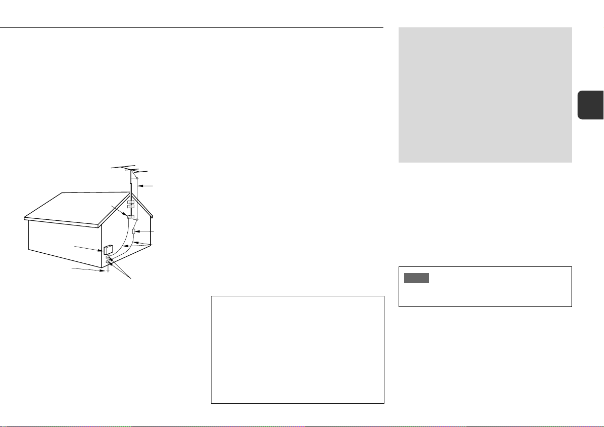
Outdoor Antenna
1 Power lines — When connecting an outdoor antenna,
make sure it is located away from power lines.
2 Outdoor antenna grounding — Be sure the antenna
system is properly grounded to provide protection against
unexpected voltage surges or static electricity build-up.
Article 810 of the National Electrical Code, ANSI/NFPA 70,
provides information on proper grounding of the mast,
supporting structure, and the lead-in wire to the antenna
discharge unit, as well as the size of the grounding unit,
connection to grounding terminals, and requirements for
grounding terminals themselves.
Antenna Grounding According
to the National Electrical Code
GROUND CLAMP
ELECTRIC
SERVICE
EQUIPMENT
POWER SERVICE
GROUNDING
ELECTRODE SYSTEM
(NEC ART 250 PART H)
NEC-NATIONAL ELECTRICAL CODE
ANTENNA
LEAD IN
WIRE
ANTENNA
DISCHARGE
UNIT
(NEC SECTION
810-20)
GROUNDING
CONDUCTORS
(NEC SECTION
810-21)
GROUND CLAMPS
Maintenance
Clean the unit only as recommended in the Operating
Instructions.
Damage Requiring Service
Have the unit serviced by a qualified service technician if:
- The AC power cord or plug has been damaged
- Foreign objects or liquid have gotten inside the unit
- The unit has been exposed to rain or water
- The unit does not seem to operate normally
- The unit exhibits a marked change in performance
- The unit has been dropped, or the cabinet has been damaged
DO NOT ATTEMPT TO SERVICE THE UNIT YOURSELF.
OWNER'S RECORD
Record the model number and serial number of your set
(found at the rear of your set) below. Refer to them when
contacting your Aiwa dealer.
Model No. _____________________________
TABLE OF CONTENTS
PRECAUTIONS .................................... 2
PREPARATIONS ................................... 4
PARTS AND CONTROLS ......................... 5
ADJUSTMENTS BEFORE OPERATION.......... 8
SOUND ADJUSTMENTS.......................... 9
CD OPERATIONS................................ 10
RADIO OPERATIONS ........................... 12
TIMER OPERATIONS ........................... 13
REFERENCE ..................................... 14
System and accessories
Main unit
Speakers
Speakers cords
Remote control
Lithium battery (CR2025)
FM antenna
AM antenna
NOTE
Do not use a cellular phone near this unit, otherwise, noise
may occur.
En
Serial No. _____________________________
3
Page 5
PREPARATIONS
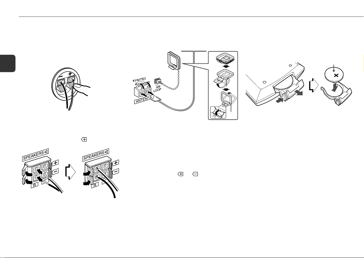
Connection
Plug in the AC power cord to the AC power outlet after all other
connections are made.
1
Connect the speaker cords to the speakers.
Connect the cords with the stripes to the + terminals and
En
the other cords to the – terminals.
2
Connect the speakers to the main unit.
Connect the right speaker to the SPEAKERS R terminals
and the left to the SPEAKERS L terminals. The speaker
cords with the stripes go to the
4
terminals.
3
Connect the supplied antennas.
Connect the FM antenna to the FM 75 Ω terminals and
the AM antenna to the AM LOOP jack.
FM antenna
AM antenna
4
Connect the AC power cord to an AC power outlet.
When the AC power cord is connected to an AC power
outlet for the first time, DEMO appears on the display.
To deactivate the DEMO, press DEMO/ECO and the clock
will flash on the display. For setting the clock, see page 9.
Speakers
•Do not short-circuit the
•Do not leave objects generating magnetism or objects
affected by magnetism near the speakers.
Antennas
Keep antennas away from metallic objects, electrical
equipment and cords.
FM antenna: Extend fully in a T-shape. If reception is poor,
connect an optional outdoor antenna to the FM 75 Ω terminals.
Be sure to connect the shield braid of the antenna to the 2
terminal.
AM antenna: Rotate to find the best reception.
and speaker cord leads.
Remote control
While sliding the latch, pull out the battery holder from the
bottom of the remote control. Place the supplied battery on
the battery holder with correct polarity. Finally , insert the holder
back into position.
CR2025
•Replace the batter y with new one when the operational
distance between the remote control and main unit becomes
shorter.
• Remove the batteries if the unit is not going to be used for
an extended period of time.
•The remote control may not operate if it is used under intense
sunlight or if its line of sight is obstructed.
Caution!
•Do not keep the battery near metallic objects such as rings,
bracelets, and keys. It may cause the battery to short circuit.
•After removing the battery, be sure to keep it out of reach of
children. In case it is swallowed, consult a doctor
immediately.
Page 6
PARTS AND CONTROLS
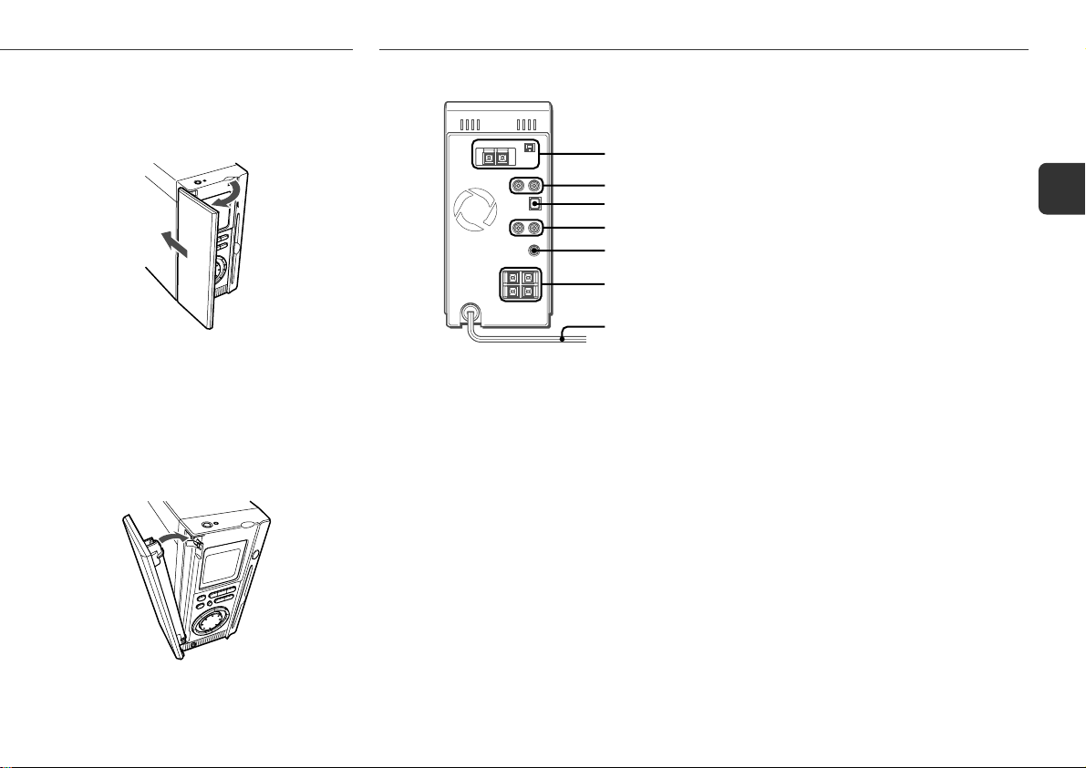
Opening the front cover
1
Pull on the right top corner of the front cover.
2
Slide it back.
1
2
When closing the front cover , slide fully towards
you, and close it.
You can operate the unit while the front cover is
closed using the remote control.
If the front cover comes off, attach as illustrated
below.
Main unit: rear
1
2
3
4
5
6
7
1 AM LOOP jack and FM 75 Ω terminals
Plug in the supplied AM and FM antennas.
2 VIDEO/AUX jacks
Accept analog sound signals from external equipment.
Connect external equipment using an optional connecting
cable with RCA phono plugs (red plug to the R jack, white
plug to the L jack). Refer also to the operating instructions
for your equipment.
To switch function to external input, press FUNCTION
repeatedly to select the AUX (VIDEO) function.
Tip:
To change a source name in the display, hold down a
and press POWER while the power is on.
AUX → VIDEO
3 DIGITAL OUT (OPTICAL) jack
CD digital sound signals can be output through this jack.
Use an optical cable to connect digital audio equipment.
Remove the dust cap from the DIGITAL OUT (OPTICAL)
jack. Then connect an optical cable plug to the DIGITAL
OUT (OPTICAL) jack.
4 LINE OUT jacks
Analog sound signals for all functions can be output
through these jacks. Use a cable with RCA phono plugs
to connect audio equipment.
Connect the red plug to the R jack, and the white plug to
the L jack.
Signals input through the VIDEO/AUX jacks are not
output from the LINE OUT jacks.
5 SUPER WOOFER3 jack
Connect an optional powered sub woofer with a built-in
amplifier to this jack.
6 SPEAKERS3 terminals
Connect the supplied speakers using the supplied
speaker cords.
7 AC power cord
En
5
Page 7

Main unit: front
1
En
2
3
4
5
1 POWER 6STANDBY/ON
Switches the unit on and off (standby).
2 FUNCTION
Switches the active function among FM/AM, AUX
(VIDEO) and CD.
3 TUNER/BAND
Selects radio function and the radio band.
4 DEMO/ECO
When the unit is turned off: selects ECO mode, DEMO
mode or displays the clock.
When the unit is turned on: selects DEMO or dimmer
mode.
6
7
8
5 PHONES jack
Plug in optional headphones set with a stereo mini plug
(ø3.5 mm,
6 zCD EJECT
Ejects the disc.
7 aSET
CD: pauses playback.
Radio: stores the received station to preset.
sCLEAR
CD: stops playback.
Radio: clears a preset station.
cPRESET
CD: starts playback.
Radio: tunes in a preset station.
f/r, t/g ( TUNING DOWN/UP)
CD: skips to a previous or a succeeding track when
pressed, searches a track in fast forward or reverse
playback when held down.
Radio: manually tunes up or down within the band.
1
/8 in.). Speaker output is canceled.
8 VOLUME/MULTI JOG
Adjusts the volume.
Clock and Timer: sets the time.
Sleep: sets the sleep timer duration.
JOG MODE
Selects repeat, random, sleep, and timer.
ENTER
Determines the mode and the time (clock and timer).
DISPLAY
CD: displays the track number being played and
remaining time of play, level indicator, and track number
being played and elapsed playing time.
Radio: displays the level indicator and the frequency of
the tuned station.
QSURROUND
Turns QSURROUND on and off.
EQ
Selects a sound equalization curve.
BBE
Enhances high frequency sound.
T-BASS
Emphasizes low frequency sound.
6
Page 8

Remote control
1,2
3
4
5
6
Buttons with the same or similar names on the main unit
basically have the same function.
1 0–9, +10
CD: selects a track of the specified number.
Radio: tunes in the station with the specified preset
number.
7
8
9
0
2
The numbered buttons take on these functions when pressed with
SHIFT held down
RANDOM/REPEAT
Selects random or repeat CD playback mode.
PROGRAM
Selects programmed CD playback mode.
DISPLAY
TIMER
Selects timer playback setting mode.
SLEEP
Selects sleep-timer setting mode.
CLOCK
Selects clock setting mode.
MONO TUNER
Switches between stereo or monaural FM reception.
3 T-BASS
4 SHIFT
Hold down when pressing a numbered button to change
its function to that printed above the number.
5 aSET
cPRESET
f/r, g/t (TUNING DO WN/UP)
sCLEAR
6 POWER
:
7 TUNER/BAND
Selects radio function and the radio band.
AUX
Selects the function of external equipment connected to
the VIDEO/AUX jacks.
CD
Selects CD function.
8 EQ
9 ENTER
0 VOLUME (N,M)
En
7
Page 9

ADJUSTMENTS BEFORE OPERATION
POWER
6STANDBY/ON
aSET
En
DEMO/ECO
TUNER/BAND
T-BASS
BBE
Power
Turning the unit on
Press POWER 6 STANDBY/ON (POWER on the remote
control).
Alternatively, press TUNER/BAND (AUX or CD on the remote
control). Playback will start automatically if a disc is inserted.
Turning the unit off
Press POWER 6STANDBY/ON again.
The unit goes into standby.
Volume
Turn VOLUME/MUL TI JOG (Press VOLUME ( N,M)
on the remote control).
Adjust from 0 (minimum) to 30 and MAX (maximum).
Tip:
Volume level setting is retained during power-off standby. If
the unit is turned off with the volume set to 22 or more, it is
automatically turned down to 21 the next time the unit is turned
on.
sCLEAR
f,g
ENTER
VOLUME/
MULTI JOG
QSURROUND
GEQ
f,g
POWER
DEMO
If the clock has not been set, a DEMO appears on the display
when the unit is turned off.
To deactivate the DEMO
Press DEMO/ECO. The clock flashes. For setting the clock,
see page 9.
ECO mode
Reduces power consumption with the following operations.
After clock is set, this unit allows you to regulate its power
consumption by displaying nothing on the display while the
power is off. This is called the power economizing
mode.
Press DEMO/ECO while the unit is turned off.
Each press of this button changes the display status as follows:
1 Demo display (power economizing mode canceled)
2 Power economizing mode
3 Clock display (power economizing mode canceled)
CLOCK
T-BASS
SHIFT
aSET
TUNER/BAND,
AUX, CD
EQ
ENTER
VOLUME
(N,M)
When the power economizing mode is activated
"Eco Mode" is displayed for 4 seconds, and everything on
the display clears.
Only the red indicator to the right of POWER lights to show
that power is being supplied to the unit.
Standby power consumption
When the power economizing mode is activated: 0.7 W
Dimmer
Adjusts the brightness of the display.
Press DEMO/ECO repeatedly while the unit is turned
on.
Each press of this button changes the display brightness as
follows:
1 Brighter display
2 DEMO
3 Darker display
If the power is turned off after changing the display brightness,
the display returns to that brightness when the power is turned
on the next time.
If the power is turned off during DEMO, the display becomes
brighter when the power is turned on again.
8
Page 10

SOUND ADJUSTMENTS
Setting the clock
1
Hold down SHIFT and press CLOCK on the remote
control.
When the unit is turned off, you can also press a or
ENTER.
2
Press f or g to set the time.
Each press changes the time in 1-minute steps.
Holding these buttons down will vary the time in 10-minute
units.
If f or g is not pressed within 4 seconds, setting
is canceled.
•You can also turn VOLUME/MULTI JOG to the right to
advance the time and to the left to move the time back.
The speed with which the time changes varies according
to how fast you turn VOLUME/MULTI JOG.
3
Press a or ENTER.
The time display stops flashing and the clock starts from
00 seconds.
To display the time while the power is on
Hold down SHIFT and press CLOCK on the remote control.
The time will be displayed for 4 seconds.
To switch to the 24-hour standard
Display the time and press s within 4 seconds.
With each press, the clock alternates between 12- and 24hour standard time.
Tip:
In the 12-hour standard, "AM12:00" indicates midnight and
"PM12:00" noon.
If the clock display flashes when the unit is turned
off
There has been a power interruption. Reset the clock.
Graphic equalizer
Selects a sound equalization curve to match the music type.
Press EQ repeatedly to select one of the three
equalization curves.
- ROCK: Powerful sound emphasizing treble and bass
- POP: More presence in the vocals and midrange
- JAZZ: Accented lower frequencies for jazz-type music
To cancel equalization
Press EQ repeatedly until the selected levels go off.
BBE
Enhances high frequencies for sound clarity.
Press BBE repeatedly to select one of the three
enhancement levels or the off position.
• If the sound becomes distorted with the BBE effect, cancel
the effect.
T-BASS
Emphasizes low frequencies for a powerful sound.
Press T-BASS repeatedly to select one of the three
emphasis levels or the off position.
•If the sound becomes distorted with the T-BASS effect, cancel
the effect.
Q SURROUND system
The Q SURROUND system built into this unit uses only two
speakers at the left and right to create an atmosphere that
sounds as if you are surrounded by two front speakers and
two rear speakers.
Press QSURROUND until "Q-SUR" appears on the
display and the QSURROUND indicator lights up.
To cancel the Q SURROUND effect
Repeat the above so that the QSURROUND indicator goes
off.
Tip:
• The Q SURROUND system does not work in monaural
mode.
•When the Q SURROUND system is on, the sound may be
distorted at higher volumes. If this happens, turn the
volume down.
En
9
Page 11

CD OPERATIONS
aSET
En
FUNCTION
JOG MODE
VOLUME/
MULTI JOG
This unit plays back finalized CD-R/RW discs as well as audio
CDs.
Playback
1
Press FUNCTION repeatedly (CD on the remote
control) to select the CD function.
2
Insert a disc with the label facing to the right and
gently push it until it is loaded automatically inside
the unit.
Do not push the disc forcibly.
Note
If you insert a disc with the label side facing to the left,
"CD Error" will be displayed. The disc will eject
automatically.
Insert it again correctly.
3
Press c to start play.
To stop playback
Press s.
10
sCLEAR
cPRESET
f,g
DISPLAY
RANDOM/
REPEAT
DISPLAY
SHIFT
f,g
cPRESET
aSET
sCLEAR
To pause playback
Press a. Press again to resume playback.
To skip to the beginning of the current/preceding/
succeeding track
Press f or g repeatedly.
To search (playback in fast forward or reverse)
Hold down f or g. Release at the desired point.
To select a track with the remote control (Direct play)
Press the numbered buttons to select a track.
- To select track 25, press +10, +10 and 5.
- To select track 10, press +10 and 0.
To change the display in the playback mode
Press DISPLAY (hold down SHIFT and press DISPLA Y on the
remote control) during playback.
The display changes in the following order:
1 Level indicator
2 Track number being played and elapsed playing time
3 Track number being played and remaining time of play
•Remaining playback time cannot be displayed during
random playback or programmed playback.
PROGRAM
0-9,+10
CD
VOLUME
(N,M)
Random/Repeat playback
Random playback plays all the tracks in random order. Repeat
playback plays all the tracks or the track being played repeatedly.
You can select random and repeat all playback at the same
time.
On the main unit
1
Press JOG MODE repeatedly so that "RANDOM"
or "REPEAT" is displayed.
2
Turn VOLUME/MULTI JOG to select one of the
following modes:
Repeat 1 playback: "" 1"
Repeat all playback: """
Random playback: "RANDOM"
3
Press c to start play.
On the remote control
1
Hold down SHIFT and press RANDOM/REPEAT
repeatedly to select one of the following modes:
Repeat 1 playback: "" 1"
Repeat all playback: """
Random playback: "RANDOM"
Random/Repeat all playback: "RANDOM ""
2
Press c to start play.
To cancel random/repeat playback
On the main unit
1 Press JOG MODE repeatedly so that "RANDOM" or
"REPEAT" is displayed.
2 Turn VOLUME/MUL TI JOG until "RANDOM", "" 1" or
""" disappears.
On the remote control
Hold down SHIFT and press RANDOM/REPEAT repeatedly
until "RANDOM", "" 1" or """ disappears.
Direct selection of the tracks with the numbered buttons
cancels the random mode.
Page 12

To repeat a selected set of tracks
First select the tracks with programmed playback.
Then selects repeat playback. (See "Programmed playback"
on this page.)
• If the random play mode is activated during "" 1" play
mode, the "" 1" will be canceled and """ will be selected.
•Direct selection of the tracks with the numbered buttons
cancels the random play mode.
Programmed playback
Plays back up to 30 selected tracks in programmed order.
1
Hold down SHIFT and press PROGRAM on the
remote control in stop mode.
"PRGM" flashes on the display.
2
Press the numbered buttons on the remote
control to program a track.
-To select the 25th track, press +10, +10 and 5.
-To select the 10th track, press +10 and 0.
The selected track number lights up on the display.
3
Repeat step 2 to program other tracks.
The total number of selected tracks and total playing time
will be displayed.
4
Press c to start play.
The track number for the current track flashes on the
display.
•During programmed playback, you cannot select a track with
the numbered buttons. "Can’t USE" is displayed when
you try to select a track .
• It is impossible to play a selected set of tracks in random
order. If attempted, "Can’t USE" will be displayed.
•If the total playback time of the program exceeds 99 minutes
and 59 seconds, or if a track with a track number exceeding
30 is programmed, the playing time is displayed as
"- -:- -".
•Y ou cannot program more than 30 tracks. "PRGM FULL"
is displayed.
To check the program
Press f or g repeatedly in stop mode. The track
number and program number are displayed in succession.
To clear the program
Press s in stop mode. "PRGM" disappears on the display .
To add tracks to the program
Repeat step 2 before starting playback. The tracks are added
to the end of the program.
To change the programmed tracks
Clear the program and repeat all the steps again.
Notes on CDs
•Do not insert more than one disc.
•Do not tilt the unit with a disc inserted.
•The unit may not play CD-R/RW discs recorded on personal
computers or certain kinds of CD-R/RW recorders.
•Do not attach adhesive label to either side of CD-R/RW discs,
as doing so may cause malfunction.
• Do not insert an unrecorded CD-R/RW disc. The disc may
be damaged.
•Do not use irregular-shaped CDs.
En
11
Page 13

RADIO OPERATIONS
POWER
6STANDBY/ON
aSET
En
TUNER/BAND
Manual tuning
1
Press TUNER/BAND repeatedly to select a band.
The unit switches to the radio from any other function
and alternates between FM and AM.
2
Press f or g repeatedly to tune in a station.
"TUNE" is displayed when a station is tuned in.
"1" lights up for FM stereo reception.
To search for a station automatically (Auto search)
Hold down f or g.
The unit searches for a station and stops at reception.
To stop the search manually, press for g.
•Auto search may not stop at stations with weak signals.
sCLEAR
cPRESET
f,g
TUNING UP/
DOWN
Preset tuning
Preset up to 32 of your favorite stations and tune them in
directly.
Presetting stations
1
2
3
•You cannot store more than 32 preset stations.
•If power is interrupted for more than approximately 12 hours,
0-9,+10
MONO
TUNER
SHIFT
f,g
cPRESET
POWER
Tune in the desired station.
Press a to store the station.
The preset number, beginning from "1", appears on the
display.
Repeat steps 1 and 2 to preset other stations.
"PRST FULL" is displayed.
all settings stored in memory after purchase need to be reset.
TUNER/
BAND
sCLEAR
aSET
Tuning in preset stations
1
Select the band.
2
Press c repeatedly.
With each press, the station with the succeeding preset
number is tuned in.
You can tune in the desired preset station directly by
pressing the numbered buttons on the remote control.
- To select preset number 10, press +10 and 0.
- To select preset number 15, press +10 and 5.
To clear a preset station
1 Tune in the station by preset tuning.
2 Press s, then press a within 4 seconds.
Preset station numbers in the band which are higher than
the cleared number decrease by one.
12
Page 14

TIMER OPERATIONS
Adjustments
To switch to monaural FM reception
Hold down SHIFT and press MONO TUNER on the remote
control so that "TUNER MONO" is displayed. To cancel,
press again to display "Auto STEREO."
Tip:
When FM stereo reception is poor, switching to monaural
reduces noise.
To switch the AM tuning interval
The default setting of the AM tuning interval is 10 kHz/step. If
you use this unit in an area where the frequency allocation
system is 9 kHz/step, change the tuning interval.
Hold down c and press POWER.
Tip:
When the AM tuning interval is changed, all preset stations
are cleared.
POWER
6STANDBY/ON
aSET
FUNCTION
JOG MODE
VOLUME/
MULTI JOG
f,g
ENTER
Sleep timer
Turns off the unit automatically after a specified time.
1
Press JOG MODE repeatedly (hold down SHIFT
and press SLEEP on the remote control).
"SLEEP" is displayed.
2
Press f or g repeatedly to set the sleep
timer duration.
With each press, the timer duration changes in 5-minute
steps between 5 to 240 minutes. If there is no button input
for 4 seconds, the current setting is entered automatically.
The unit turns off after the selected time.
•VOLUME/MUL TI JOG is also available in place of f
or g.
To check the remaining time until the unit turns off
Press JOG MODE repeatedly (hold down SHIFT and press
SLEEP on the remote control). The remaining time is displayed
for 7 seconds.
SLEEP
TIMER
MONO TUNER
SHIFT
f,g
POWER
aSET
To cancel the sleep timer
Press JOG MODE and turn VOLUME/MULTI JOG (hold down
SHIFT and press SLEEP repeatedly on the remote control)
until "SLEEP OFF" is displayed.
TUNER/BAND,
AUX, CD
ENTER
Timer playback
Turns on the unit at a specified time for the specified duration.
Make sure the clock is set correctly.
1
Press FUNCTION repeatedly to select the desired
playback source.
2
On the main unit
1 Press JOG MODE repeatedly so that "TIMER
OFF" is displayed.
2 Within 7 seconds, turn VOLUME/MULTI JOG
so that "TIMER 5 PLAY" is displayed and "5"
indicator lights up.
On the remote control
1 Hold down SHIFT and press TIMER.
"5" indicator lights up and "TIMER 5 PLAY"
appears on the display. Then, the timer-on time and
the source name appear alternately on the display.
13
En
Page 15

En
3
Within 7 seconds, press ENTER.
The timer-on time and the source name appear alternately
on the display.
4
Press f or g to set the timer -on time, then
press ENTER.
5
Press f or g to set the timer-activated
duration, then press ENTER.
With each press, the timer-activated duration changes in
5-minute steps between 5 to 240 minutes.
If there is no button input for 4 seconds, the current setting
is entered automatically.
•VOLUME/MULTI JOG is also available in place of f
or g.
6
Adjust the volume and tone for timer playback.
If the volume level is set to 22 or higher, it is automatically
turned down to 21 when the unit is turned on by the timer.
7
Prepare the source.
To play CD, insert a disc.
To play the radio, select the band and tune in the desired
station.
To play external equipment connected to the VIDEO/AUX
jacks, set an external timer for the equipment so that its
playback begins at the same time.
8
Press POWER 6STANDBY/ON to turn the unit
off.
"5" remains on the display to indicate the timer standby
mode (when the ECO mode is deactivated).
At timer-on time, the unit turns on and plays the selected
source. After the specified timer-activated duration, the
unit turns off again.
• Timer playback will not begin unless the unit is turned off
first.
•Connected equipment cannot be turned on or off by the builtin timer of this unit. Use an external timer.
To check the timer setting
Hold down SHIFT and press TIMER.
The timer-on time, the source and the timer-activated duration
are displayed for 4 seconds.
To change the timer setting
Reset the timer again.
To cancel the timer
On the main unit
Press JOG MODE to display "TIMER 5 PLAY" and turn
VOLUME/MULTI JOG so that "TIMER OFF" is displayed.
Then press ENTER. "5" disappears from the display.
On the remote control
Hold down SHIFT and press TIMER repeatedly until
"TIMER OFF" is displayed. "5" disappears from the
display.
Tip:
Your timer setting is retained even if the timer is canceled.
Next time the timer is activated, you can change your previous
setting, or simply use the same setting again.
REFERENCE
Care and maintenance
Occasional care and maintenance of the unit and the software
are needed to optimize the performance of your unit.
To clean the cabinet
Use a soft and dry cloth. If the unit surfaces are extremely
dirty, use a soft cloth lightly moistened with mild detergent
solution. Do not use strong solvents such as alcohol, benzene
or thinner.
Care of CDs
When a CD becomes dirty, wipe it from the center out with a
cleaning cloth. After playing a CD, store it in its case. Do not
keep it in hot or humid places.
Troubleshooting
If your unit fails to perform properly, check the following guide
and the relevant sections of this manual.
There is no sound
•Are the speakers and AC power cord connected properly?
The unit shut off suddenly
•Possibly a short circuit in the speaker terminals. Disconnect
the AC power cord from the AC outlet and reconnect the
speaker cords correctly.
All the display lights turn off when the power is off
• Is ECO mode set to on?
Erroneous display
•Reset the unit.
14
Page 16

Poor radio reception
• Check antenna connection. Adjust the antenna to find the
best reception.
•Move unit and antenna away from other electric appliances
and cords.
The CD player works poorly
•Is the disc correctly inserted?
•Is the disc dirty?
•Is the lens affected by condensation? If so, wait
approximately one hour and try again.
The disc cannot be ejected
•If the disc cannot be ejected by pressing z CD EJECT , turn
off the power and press z CD EJECT while holding down
DISPLAY until the disc comes out. Then press POWER to
turn the unit on again.
Resetting the unit
If an unusual condition occurs in the display window, reset
the unit as follows:
1 Press POWER to turn off the power.
If the power cannot be turned off, disconnect the AC power
cord, then plug it in again.
2 Hold down s and press POWER.
Everything stored in memory after purchase is cleared.
Specifications
MAIN UNIT
TUNER
FM tuning range 87.5 MHz to 108 MHz
FM usable sensitivity (IHF) 13.2 dBf
FM antenna terminals 75 ohms (unbalanced)
AM tuning range 530 kHz to 1710 kHz (10 kHz step)
531 kHz to 1602 kHz (9 kHz step)
AM usable sensitivity 350 µV/m
AM antenna Loop antenna
AMPLIFIER
Power output 12 W + 12 W (50 Hz - 20 kHz, THD
less than 1%, 6 ohms)
15 W + 15 W (1 kHz, THD less than
10%, 6 ohms)
Total harmonic distortion 0.05% (6 W, 1 kHz, 6 ohms, DIN
AUDIO)
Input VIDEO/AUX: 600 mV
Outputs SPEAKERS: 6 ohms or more
PHONES: 16 ohms or more
SUPER WOOFER 0.85 V
DIGITAL OUT (OPTICAL) jack
LINE OUT jack
CD PLAYER
Laser Semiconductor laser (λ = 780 nm)
D/A converter 1 bit dual
Signal-to-noise ratio 85 dB (1 kHz, 0 dB)
Harmonic distortion 0.08% (1 kHz, 0 dB)
Wow and flutter unmeasurable
GENERAL
Power requirements 120 V AC, 60 Hz
Power consumption 45 W
Power consumption With ECO mode on: 0.7 W
in standby mode With ECO mode off: 13 W
Dimensions (W × H × D) 100.0 × 205.0 × 292.5 mm
(4 × 8 1/8 × 11 5/8 in.)
Weight 3.5 kg (7 lbs 12 oz)
SPEAKER SYSTEM
Speaker system 2 way, bass reflex (magnetic
shielded)
Speaker units Woofer: 85 mm (3 3/8 in.) cone
Tweeter: 22 mm (29/32 in.) dome
Impedance 6 ohms
Dimensions (W × H × D) 100 × 210 × 185 mm
(4 × 8 3/8 × 7 3/8 in.)
Weight 1.5 kg (3 lbs 5 oz)
Specifications and external appearance are subject to change
without notice.
BBE SYSTEM
The word "BBE" and the "BBE symbol" are trademarks of BBE
Sound, Inc.
Under License from BBE Sound, Inc.
15
En
Page 17

NOTE
This equipment has been tested and found to comply with the
limits for a Class B digital device, pursuant to Part 15 of the
FCC Rules. These limits are designed to provide reasonable
protection against harmful interference in a residential
installation.
This equipment generates, uses, and can radiate radio frequency
energy and, if not installed and used in accordance with the
instructions, may cause harmful interference to radio
communications. However, there is no guarantee that
interference will not occur in a particular installation. If this
equipment does cause harmful interference to radio or television
reception, which can be determined by turning the equipment
off and on, the user is encouraged to try to correct the
interference by one or more of the following measures:
- Reorient or relocate the receiving antenna.
- Increase the separation between the equipment and receiver.
- Connect the equipment into an outlet on circuit different from
that to which the receiver is connected.
- Consult the dealer or an experienced radio/TV technician for
help.
CAUTION
Modifications or adjustments to this product, which are not
expressly approved by the manufacturer, may void the user’s
right or authority to operate this product.
For assistance and information
Printed in Malaysia
(United States and Puerto Rico)
Page 18

Faible réception radio
• Vérifiez la connexion de l'antenne. Ajustez l'antenne pour
trouver la meilleure réception.
•Placez l'appareil et l'antenne à l'écart d'autres appareils
électriques et de cordons.
Le lecteur CD marche mal
•Le disque est-il correctement introduit?
•Le disque est-il sale?
• La lentille est-elle affectée par la condensation? Si c'est le
cas, attendez approximativement une heure et essayez à
nouveau.
Le disque ne peut pas s'éjecter
• Si le disque ne peut pas s'éjecter en appuyant sur z CD
EJECT , mettez l'appareil hors tension et appuyez sur z CD
EJECT tout en maintenant enfoncé DISPLAY jusqu'à ce que
le disque sorte. Puis appuyez sur POWER pour mettre de
nouveau l'appareil sous tension.
Régler l'appareil à nouveau
Si un problème inhabituel arrive sur la fenêtre d'affichage,
réglez à nouveau l'appareil comme suit:
1 Appuyez sur POWER pour couper l'alimentation.
Si l'alimentation ne peut pas être coupée, débranchez le
cordon d'alimentation secteur, puis rebranchez-le.
2 Maintenez enfoncé s et appuyez sur POWER.
Tout ce qui a été mémorisé après l'achat est effacé.
Spécifications
UNITÉ PRINCIPALE
TUNER
Plage d'accord FM 87,5 MHz à 108 MHz
Sensibilité utilisable FM (IHF)13,2 dBf
Bornes d'antenne FM 75 ohms (déséquilibré)
Plage d'accord AM
Sensibilité utilisable AM 350 µV/m
Antenne AM Antenne cadre
AMPLIFICATEUR
Sortie de puissance 12 W + 12 W (50 Hz - 20 kHz, THD
Distorsion harmonique totale 0,05% (6 W, 1 kHz, 6 ohms, DIN
Entrée VIDEO/AUX: 600 mV
Sorties SPEAKERS: accepte des enceintes
LECTEUR CD
Laser Laser Semi-conducteur
Convertisseur N-A 1 bit double
Rapport signal/circuit 85 dB (1 kHz, 0 dB)
Distorsion harmonique 0,08% (1 kHz, 0 dB)
Pleurage et scintillement Non mesurable
530 kHz à 1710 kHz (étapes de 10 kHz)
531 kHz à 1602 kHz
(étapes de 9 kHz)
moins de 1%, 6 ohms)
15 W + 15 W (1 kHz, THD moins de
10%, 6 ohms)
AUDIO)
de 6 ohms ou plus
PHONES: accepte des écouteurs de
16 ohms ou plus
SUPER WOOFER: 0,85 V
Prises DIGITAL OUT (OPTICAL)
Prise LINE OUT
(λ = 780 nm)
GÉNÉRALITÉS
Alimentation secteur 120 V secteur, 60 Hz
Consommation 45 W
Consommation en 0,7 W (mode ECO activé)
mode d'attente 13 W (mode ECO désactivé)
Dimensions (L × H × P) 100,0 × 205,0 × 292,5 mm
Poids de l'unité principale 3,5 kg
SYSTÉME ENCEINTE
Système d'enceintes 2 voies, bass reflex (protégé
magnétiquement)
Appareils d'enceintes Enceinte de basses: cône de 85 mm
Enceinte d'aigus: cône de 22 mm
Impédance 6 ohms
Dimensions (L × H × P) 100 × 210 × 185 mm
Poids 1,5 kg
Les spécifications et l’apparence externe sont sujettes aux
changements sans notice.
SYSTÈME BBE
L'appellation "BBE" et le "symbole BBE" sont des marques de
fabrique de BBE Sound, Inc.
Sous licence de BBE Sound Inc.
F
43
 Loading...