

Sony XR-M550, XR-M500R Service Manual

XR-M500R/M550
SERVICE MANUAL
Dolby noise reduction manufactured under license from
Dolby Laboratories Licensing Corporation.
“DOLBY” and the double-D symbol ; are trademarks
of Dolby Laboratories Licencing Corporation.
SPECIFICATIONS
AUDIO POWER SPECIFICATIONS (US model)
POWER OUTPUT AND TOTAL HARMONIC DISTORTION
19 watts per channel minimum continuous average power into
4 ohms, 4 channels driven from 20 Hz to 20 kHz with no more
than 1% total harmonic distortion.
US Model
Canadian Model
XR-M550
AEP Model
UK Model
XR-M500R
Photo: XR-M550
Model Name Using Similar Mechanism NEW
T ape Transport Mechanism Type MG-25E-136
Other specifications
Cassette player section
Tape track 4-track 2-channel stereo
Wow and flutter 0.08 % (WRMS)
Frequency response 30 – 20,000 Hz
Signal-to-noise ratio
Dolby NR off
61 dB
58 dB
87.5 – 107.9 MHz (XR-M550)
10.7 MHz/450kHz
8 dBf
75 dB at 400 kHz
IV
Dolby B NR
67 dB
64 dB
Cassette type
TYPE II,
TYPE I
Tuner section
FM
Tuning range 87.5 – 108.0 MHz (XR-M500R)
Antenna terminal External antenna connector
Intermediate frequency
Usable sensitivity
Selectivity
FM/AM (MW/LW) CASSETTE CAR STEREO
Signal-to-noise ratio 66 dB (stereo),
Harmonic distortion at 1 kHz
Separation 35 dB at 1 kHz
Frequency response 30 – 15,000 Hz
MW/LW (XR-M500R)
Tuning range MW: 531 – 1,602 kHz
Aerial terminal External aerial connector
Intermediate frequency 10.7 MHz/450 kHz
Sensitivity MW: 30 µV
AM (XR-M550)
Tuning range 530 – 1,710 kHz
Antenna terminal External antenna connector
Intermediate frequency 10.7 MHz/450 kHz
Sensitivity 30 µV
72 dB (mono)
0.6 % (stereo),
0.3 % (mono)
LW: 153 – 279 kHz
LW: 40 µV
– Continued on next page –

Power amplifier section
Outputs Speaker outputs
Speaker impedance 4 – 8 ohms
Maximum power output 50 W × 4 (at 4 ohms)
General
Outputs Audio output (2) (M500R)
Inputs Telephone ATT control
Tone controls Bass ±9 dB at 100 Hz
Power requirements 12 V DC car battery
Dimensions Approx. 178
Mounting dimensions Approx. 182 × 53 × 163 mm
Mass Approx. 1.3 kg (2lb. 14 oz.)
Supplied accessories Card remote commander
Design and specifications are subject to change
without notice.
Audio output (3) (M550)
Power aerial relay control
lead
Power amplifier control
lead
lead
Illumination control lead
Treble ±9 dB at 10 kHz
(negative earth)
1
(7
/8 × 2 × 7 4/1 in.)
(w/h/d)
1
(7
/4 × 2 1/8 × 6 1/2 in.)
(w/h/d)
RM-X96 (XR-M500R)
RM-X94 (XR-M550)
Parts for installation and
connections (1 set)
× 50 × 182 mm
TABLE OF CONTENTS
1. SERVICING NOTES
............................................... 3
2. GENERAL
Location of Controls (XR-M500R) ................................ 4
Setting the Clock ............................................................. 4
Changing the Sound and Display Setting....................... 4
Locations of Controls (XR-M550) ................................. 5
Setting the Clock ............................................................. 5
Changing the Sound and Display Setting....................... 5
Installation (XR-M500R)................................................ 6
Installation (XR-M550) .................................................. 7
Connections (XR-M500R).............................................. 8
Connections (XR-M550) ................................................ 12
3. DISASSEMBLY ......................................................... 15
4. ASSEMBLY................................................................. 19
5. MECHANICAL ADJUSTMENTS ....................... 24
6. ELECTRICAL ADJUSTMENTS
Tape Deck Section .......................................................... 24
Tuner Section .................................................................. 25
7. DIAGRAMS
7-1. Block Diagram – TUNER/TAPE Section – .................. 27
7-2. Block Diagram – MAIN Section – ................................ 28
7-3. Block Diagram
– DISPLAY/BUS CONTROL Section – ....................... 29
7-4. Block Diagram – POWER SUPPLY Section – ............. 30
7-5. Note for Printed Wiring Boards and
Schematic Diagrams ....................................................... 31
7-6. Printed Wiring Board
– MAIN Board (Component Side) – .............................. 32
7-7. Printed Wiring Board
– MAIN Board (Conductor Side) – ................................ 33
7-8. Schematic Diagram – MAIN Board (1/4) – .................. 34
7-9. Schematic Diagram – MAIN Board (2/4) – .................. 35
7-10. Schematic Diagram – MAIN Board (3/4) – .................. 36
7-11. Schematic Diagram – MAIN Board (4/4) – .................. 37
7-12. Printed Wiring Board –SUB Board – ............................ 38
7-13. Schematic Diagram – SUB Board – .............................. 39
7-14. Printed Wiring Board – DISPLAY Board – .................. 40
7-15. Schematic Diagram – DISPLAY Board – ..................... 41
7-16. IC Pin Function Description ........................................... 44
8. EXPLODED VIEWS................................................ 51
9. ELECTRICAL PARTS LIST ............................... 55
Flexible Circuit Board Repairing
• Keep the temperature of the soldering iron around 270 ˚C dur-
ing repairing.
• Do not touch the soldering iron on the same conductor of the
circuit board (within 3 times).
• Be careful not to apply force on the conductor when soldering
or unsoldering.
Notes on chip component replacement
• Never reuse a disconnected chip component.
• Notice that the minus side of a tantalum capacitor may be dam-
aged by heat.
2
SECTION 1
m
r
SERVICING NOTES
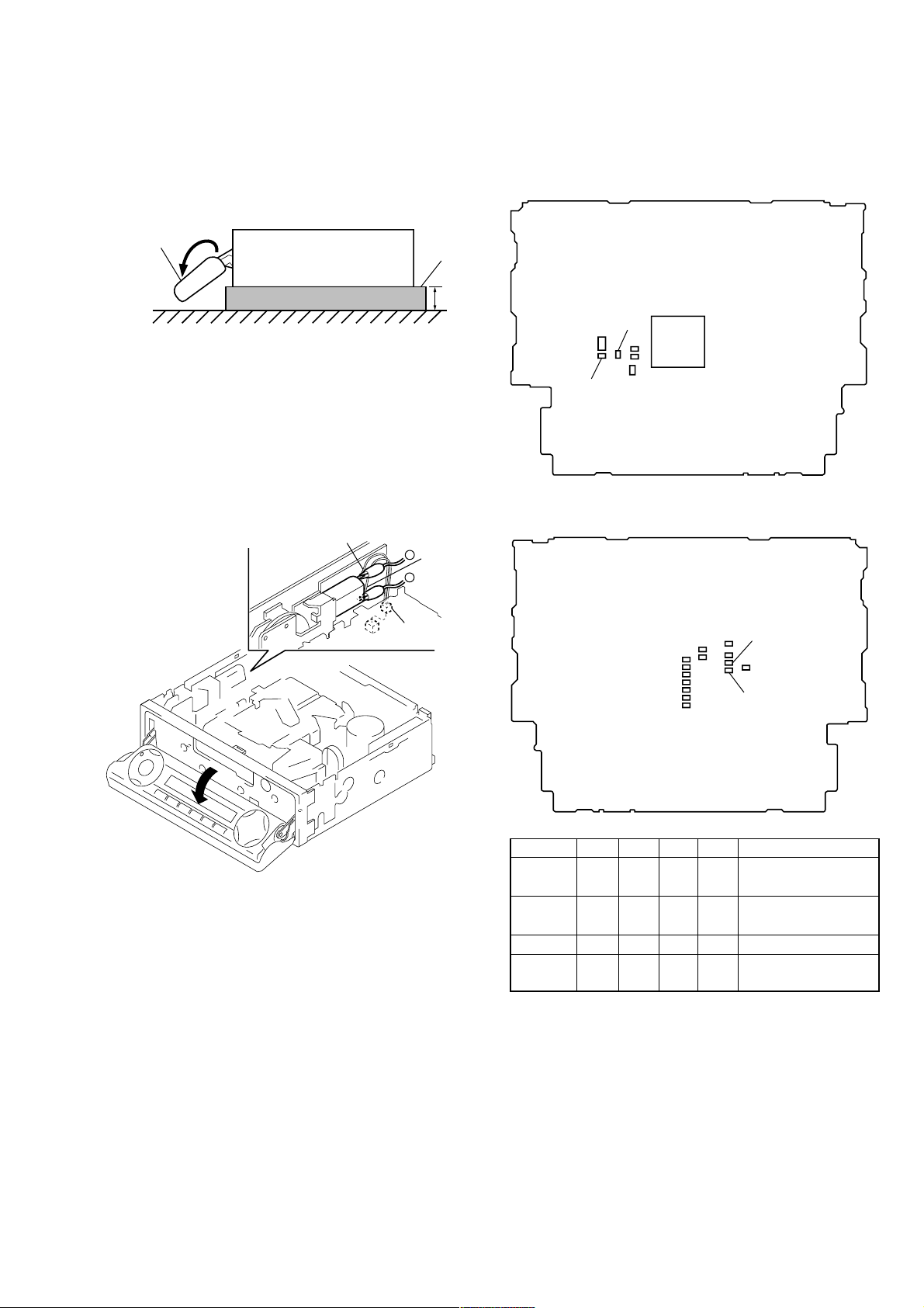
PRECAUTION ON OPEN/CLOSE FRONT PANEL
The front panel opens to the bottom of main unit.
In performing the repair, place the main unit on the base having
the height exceeding 1 cm.
front panel
XR-M500R/M550
( SIDE VIEW)
base
1c
Open the front panel by supplying the power through the following steps:
1. Disconnect the motor connector (CN501) from main board.
2. Supply the power to the motor.
Voltage : 9 V
Violet wiring : MOTOR –
Gray wiring : MOTOR +
gray wiring
–
+
violet
wiring
MODEL IDENTIFICATION
There are four types of main board in according of destination for
XR-M500R.
– MAIN BOARD (Componet Side) –
R719
IC601
R720
– MAIN BOARD (Conductor Side) –
connecto
(CN501)
R625 R626 R719 R720 Indicated language
TYPE A aa ××
TYPE B ××aa
TYPE C × aa × English, German
TYPE D a ××a
R625
R626
English, Spanish,
Swedish, Portuguese
German, Italian, Dutch,
French
English, Polish, Czeck,
Turkish
TYPE A, B, C, or D can also be identified from the front panel
display language.
For a switching method of display language, see page 4.
3

(XR-M500R)5(XR-M550)
Location of controls
Security side
Operation side
T
Y
P
P
S
L
D
SOURCE
OFF
M
O
REP SHUF
123 456
D
E
XR-M500R
SECTION 2
GENERAL
The corresponding buttons of the unit
control the same functions as those on
the card remote commander.
10 Reset button 8
2 Main display window
3 OPEN button 38
4qa Receptor for the card remote
commander
5 Volume adjust buttons
6 DSPL/PTY (display mode change/
programme type) button
7 Sub display window
8 MENU button
Z (eject) button 11
9
qs LIST button
qd OFF button*
qf MODE button
qg SOURCE (TUNER/TAPE/CD/MD) button
qh AF button 16, 18
qj Number buttons
During radio reception:
During tape playback:
LIST
U
DISC
N
E
M
D-BASS
SOUND
R
E
T
N
DISC
TAAF
E
CLOSE
During CD/MD playback:
9
Preset number select
13, 14, 17, 33, 34
(1) REP 12
(1) REP 28
(2)
SHUF 28
This section is extracted from
instruction manual.
qk TA button 16, 17, 18
ql SOUND button
w; PRST/DISC +/– (cursor up/down) buttons
SEEK/AMS –/+ (cursor left/right) buttons
13
wa ENTER button
ws CLOSE button
wd D-BASS button
* Warning when installing in a car
without ACC (accessory) position on
the ignition key switch
Be sure to press (OFF) on the unit for
two seconds to turn off the clock display
after turning off the engine.
When you press (OFF) only momentarily,
the clock display does not turn off and this
causes battery wear.
6
Setting the clock
The clock uses a 24-hour digital indication.
Example: To set the clock to 10:08
1 Press (MENU), then M or m repeatedly
until “Clock” appears.
1 Press (ENTER).
The hour indication flashes.
2 Press M or m to set the hour.
3 Press ,.
The minute indication flashes.
4 Press M or m to set the minute.
Tips
• You can use the convenient CT function to set
the clock automatically (page 20).
• When the D.Info mode is set to “on,” the time is
always displayed (except for some functions of
SA mode) (page 23).
Changing the sound and
display settings
The following items can be set:
Set (Setting)
•Clock (page 10).
•CT (Clock Time) (page 20).
•Beep — to turn the beep sound on or off.
•RM (Rotary Commander) — to change the
operative direction of the rotary commander.
— Select “norm” to use the rotary
commander as the factory-set position.
— Select “rev” when you mount the rotary
commander on the right side of the
steering column.
•English/Spanish/Portuguese/Swedish — to
change the display language to English,
Spanish, Portuguese or Swedish.
Dis (Display)
•D.Info (Dual Information) — to display the
clock and the play mode simultaneously (on),
or to display the information alternately (off).
•SA (Spectrum Analyzer) — to change the
display pattern of the equalizer display
(page 25).
•Dimmer — to change the brightness of the
display (When the Illumination terminal
connected).
— Select “on” to dim the display.
— Select “off” to deactivate Dimmer.
•Contrast — to adjust the contrast if the
indications in the display are not
recognisable because of the unit’s installed
position.
•M.Dspl (Motion Display) — to turn the
motion display on or off.
•A.Scrl (Auto Scroll) (page 27).
continue to next page t
1 Press (MENU).
2 Press M or m repeatedly until the desired
item appears.
Each time you press m, the item changes as
follows:
Example
Clock t CT t Beep t RM t English/
Spanish/Portuguese/Swedish t D.Info t SA
t Dimmer t Contrast t M.Dspl*
1
*
When no CD or MD is playing, this item will
not appear.
2
*
When the radio is off, or when no tape, CD,
or MD is playing, this item will not appear.
Note
The displayed item will differ depending on the
source.
Tip
You can easily switch among categories (“Set,”
“Snd” (Sound), “P/M” (Play Mode) and “Dis”) by
M
or m for two seconds.
pressing
3 Press , to select the desired setting
(Example: on or off).
4 Press (ENTER).
After the mode setting is complete, the
display returns to normal playback mode.
1
t A.Scrl*
7
2
2 Press (ENTER).
The clock starts.
10
4
23
24


(XR-M500R)7(XR-M550)
Installation
Instalación
Montering
Instalação
Precautions
•If you mount other Sony equipment with this
unit, it is better to mount this unit in the lower
position.
•There must be a distance of at least 15 cm
between the cassettes slot of the unit and shift
lever to insert cassette easily. Choose the
installation location carefully so the unit does
not interfere with gear shifting and other driving
operations.
•When the front panel is open, a portion of it will
extend down from the unit. When you install the
unit, make sure that this portion of the front
panel is not obstructed in its open position (by
the ashtray, for example).
•Choose the installation location carefully so that
the unit will not interfere with normal driving
operations.
•Avoid installing the unit in areas subject to dust,
dirt, excessive vibration, or high temperatures,
such as in direct sunlight or near heater ducts.
•Use only the supplied mounting hardware for a
safe and secure installation.
Mounting angle adjustment
Adjust the mounting angle to less than 20°.
Precauciones
•Si monta otro equipo Sony con esta unidad, es
preferible montar esta unidad en la posición más
baja.
•Para que sea posible insertar la cinta con
facilidad, debe haber una distancia de al menos
15 cm entre la ranura de inserción de cintas de la
unidad y la palanca de cambios.
Instale la unidad en un lugar que no entorpezca
las operaciones de cambio de marchas o de
conducción en general.
•Cuando el panel frontal está abierto, una parte
de él sobresaldrá de la unidad. Cuando instale la
unidad, compruebe que dicha parte del panel
frontal no queda obstruida en la posición de
apertura (debido al cenicero, por ejemplo).
•Elija cuidadosamente el lugar de montaje de
forma que la unidad no interfiera las funciones
normales de conducción.
•Evite instalar la unidad donde pueda quedar
sometida a altas temperaturas, como a la luz
solar directa o al aire de calefacción, o a polvo,
suciedad, o vibraciones excesivas.
•Para realizar una instalación segura y firme,
utilice solamente la ferretería de montaje
suministrada.
Ajuste del ángulo de montaje
Ajuste el ángulo de montaje a menos de 20°.
15
cm
Säkerhetsföreskrifter
•Om du monterar annan Sony-utrustning till
denna enhet är det bäst att montera denna enhet
i det undre läget.
•För att du ska kunna sätta i och ta ut bandet
måste avståndet vara minst 15 cm mellan
kassettfacket på enheten och växelspaken. När
du installerar enheten väljer du en plats så att
enheten inte är i vägen när du kör.
•När frontpanelen är öppen befinner sig en liten
del av den under enhetens bottenplan. Se till att
du installerar enheten så att den här delen går fri
(från t.ex. askkoppen) när frontpanelen är
öppen.
•Var noga när du väljer var i bilen du monterar
bilstereon, så att den inte sitter i vägen när du
kör.
•Montera inte bilstereon där den utsätts för
värme,
t ex solsken eller varmluft, eller där den utsätts
för damm, smuts och/eller vibrationer.
•Använd endast de medföljande
monteringstillbehören för att vara säker på att
bilstereon monteras på ett säkert och korrekt
sätt.
Tillåten monteringsvinkel
Monteringsvinkeln får inte vara större än 20
grader.
Extended portion of the front panel.
Parte sobresaliente del panel frontal.
Utskjutande del av frontpanelen.
Parte extensível do painel frontal.
8.5 mm
15.5 mm
Precauções
•É preferível montar este aparelho na posição
mais baixa, se quiser montar simultaneamente
outros equipamentos da Sony.
•Para colocar com facilidade a cassete, deve haver
uma distância de pelo menos 15 cm entre a
ranhura de introduçäo da cassete e a alavanca
das mudanças.
Escolha o local de instalaçäo de forma a que o
aparelho näo interfira com as mudanças de
velocidade ou com as outras manobras de
conduçäo.
•Quando o painel frontal estiver aberto, pode
puxar a parte extensível baixo. Quando instalar
a unidade, verifique se essa parte do painel
frontal não está presa na posição aberta (pelo
cinzeiro, por exemplo).
•Escolha com cuidado um local apropriado para
a montagem do aparelho, para que este não
interfira com as manobras necessárias à
condução do veículo.
•Evite instalar o aparelho onde possa estar sujeito
a altas temperaturas, como em locais expostos
directamente à luz do sol, ao ar quente dos
aquecimentos, ou sujeitos a pó, sujidade ou
vibração excessiva.
•Para efectuar uma instalação segura utilize
unicamente o hardware de montagem fornecido.
Ajuste do ângulo de montagem
Ajuste o ângulo de montagem a menos de 20°.
Installation in the dashboard Instalación en el salpicadero Montera på instrumentbrädan Instalação no tablier
1 2 3
Bend these claws outward
for a tight fit, if necessary.
Si es necesario, doble estas
1
Note
To prevent malfunction, install only with the supplied
5
.
screws
Reset button
When the installation and connections are
complete, be sure to press the reset button with a
ballpoint pen, etc.
uñas hacia afuera para que
encaje firmemente.
För att få en tät passning
böj dessa flikar vid behov.
Se necessário, dobre as
unhas para prender melhor.
Nota
Para evitar fallos de funcionamiento, realice la
instalación únicamente con los tornillos suministrados
5
.
Botón de restauración
Cuando finalice la instalación y las conexiones,
cerciórese de pulsar el botón de restauración con
un bolígrafo, etc.
4
Dashboard
Salpicadero
Instrumentbräda
Tablier
1
5
5
7
7
7
5
Observera
Använd bara de medföljande skruvarna
undviker du onödiga fel.
Nollställningsknappen
Kom ihåg att använda en penna eller något annat
spetsigt föremål för att trycka på
nollställningsknappen när anslutningen och
monteringen är klar.
4
With the UP marking up
Con la marca UP hacia arriba
Med märkningen UP vänd uppåt
Com a marca UP para cima
5
, så
Nota
Para evitar avarias, instale o aparelho apenas com os
parafusos fornecidos
Botão de reinicialização
Quando terminar a instalação e as ligações, não se
esqueça de carregar no botão de reinicialização
com a ponta de uma caneta, esferográfica, etc.
5
.
Fire wall
Panel cortafuegos
Brandsäker
mellanvägg
Painel corta-fogo
2
3
6


(XR-M500R)
Connections
Cautions
•This unit is designed for negative earth 12 V DC
operation only.
•Be careful not to pinch any wires between a
screw and the body of the car or this unit or
between any moving parts such as the seat
railing, etc.
•Connect the power connecting cord 8 to the
unit and speakers before connecting it to the
auxiliary power connector.
•Run all earth wires to a common earth point.
•Connect the yellow cord to a free car circuit
rated higher than the unit’s fuse rating. If you
connect this unit in combination with other
stereo components, the car circuit they are
connected to must be rated higher than the sum
of the individual components’ fuse rating. If
there are no car circuits rated as high as the
unit’s fuse rating, connect the unit directly to the
battery. If no car circuits are available for
connecting this unit, connect the unit to a car
circuit rated higher than the unit’s fuse rating in
such a way that if the unit blows its fuse, no
other circuits will be cut off.
Warning when installing in a car
without ACC (accessory) position
on the ignition key switch
Be sure to press (OFF) on the unit for two
seconds to turn off the clock display after
turned off the engine.
When you press (OFF) momentarily, the clock
display does not turn off and this causes battery
wear.
Conexiones
Precauciones
•Esta unidad ha sido diseñada para alimentarse
con 12 V CC, negativo a masa, solamente.
•Tenga cuidado de no atrapar ningún cable entre
algún tornillo y la carrocería del automóvil o
esta unidad o entre las partes móviles, como por
ejemplo los raíles del asiento, etc.
•Conecte el cable de conexión de alimentación 8
a la unidad y los altavoces antes de conectarlo al
conector de alimentación auxiliar.
•Conecte todos los conductores de puesta a
masa a un punto común.
•Conecte el cable amarillo a un circuito libre del
automóvil de potencia nominal superior a la del
fusible de la unidad. Si conecta esta unidad en
combinación con otros componentes estéreo, la
potencia nominal del circuito del automóvil a los
que dichos componentes estén conectados debe
ser superior a la suma de la potencia nominal
del fusible de los componentes. Si no existen
circuitos de automóvil de potencia nominal tan
alta como la del fusible de la unidad, conecte
ésta directamente a la batería. Si no hay circuitos
de automóvil disponibles para conectar esta
unidad, conecte la misma a un circuito de
automóvil de potencia nominal superior a la del
fusible de la unidad de forma que no se
desactiven otros circuitos si el fusible de dicha
unidad se funde.
Advertencia sobre la instalación
en un automóvil que no
disponga de posición ACC
(accesorios) en el interruptor de
la llave de encendido
Asegúrese de pulsar (OFF) en la unidad
durante dos segundos para desactivar la
indicación del reloj una vez apagado el motor.
Si pulsa (OFF) momentáneamente, la indicación
del reloj no se desactivará y esto causará el
desgaste de la batería.
Anslutning
Säkerhetsföreskrifter
•Denna bilstereo är endast avsedd för anslutning
till ett negativt jordat, 12 V bilbatteri.
•Var noga med att inga kablar kläms mellan
någon skruv eller att de blir klämda mellan
rörliga delar som t.ex. bilsätet.
•Anslut strömkabeln 8 till enheten och
högtalarna innan du ansluter den till den yttre
strömanslutningen.
•Dra samtliga jordledningar till en och samma
jordningspunkt.
•Anslut den gula kabeln till en ledig bilkrets med
ett högre amperetal än enhetens. Om du kopplar
både denna enhet och andra stereokomponenter
till en och samma bilkrets, måste den bilkrets de
kopplas till ha en högre ampere än summan av
de enskilda delarnas amperestyrka. Om det inte
finns några bilkretsar med en så hög
amperestyrka som enhetens ska du ansluta
enheten direkt till batteriet. Om inga bilkretsar
finns för anslutning till enheten ska du ansluta
enheten till en bilkrets med ett högre amperetal
än enhetens säkring, så att det är denna som går
i stället för bilens.
Var försiktig när du gör
installationen i en bil där
tändningslåset saknar
tillbehörsläge (ACC)
Glöm inte att trycka på (OFF) på enheten
under två sekunder för att stänga av klockans
teckenfönster efter det att du har stängt av
motorn.
Om du bara trycker på (OFF) ett kort ögonblick
slocknar inte klockans teckenfönster vilket kan
leda till att batteriet laddas ur.
Ligações
Cuidado
•Este aparelho foi concebido para funcionar
somente com corrente contínua de 12 V com
negativo à massa.
•Tenha cuidado para que os fios não fiquem
entalados entre os parafusos e a carroçaria do
automóvel ou a caixa do aparelho, nem entre as
peças móveis, por exemplo, as calhas dos
bancos, etc.
•Ligue o cabo de alimentação de corrente 8 ao
aparelho e aos alifalantes antes de o ligar ao
conector de corrente auxiliar.
•Ligue todos os cabos de massa num ponto de
massa comum.
•Ligue o cabo amarelo a um circuito eléctrico
livre do automóvel, cuja potência nominal seja
superior à dos fusíveis do aparelho. Se ligar este
aparelho em série com outros componentes
estéreo, a potência nominal do circuito eléctrico
do automóvel onde os ligar tem de ser superior
à soma da potência nominal dos fusíveis de
todos os componentes individuais. Se não
houver nenhum circuito eléctrico do automóvel
com uma potência nominal tão elevada como a
dos fusíveis do aparelho, ligue-o directamente à
bateria. Se não estiver disponível nenhum
circuito eléctrico do automóvel para ligação
deste aparelho, ligue-o a um circuito eléctrico do
automóvel com uma potência nominal superior
à dos fusíveis do aparelho, de tal modo que, se o
aparelho rebentar os fusíveis respectivos,
nenhum outro circuito seja cortado.
Aviso sobre a instalação num
automóvel sem posição ACC
(acessórios) na chave de ignição
Verifique se carregou em (OFF) no aparelho
durante dois segundos para desactivar o visor
do relógio depois de ter desligado o motor.
Se carregar ligeiramente em (OFF), não desactiva
o visor do relógio o que provoca o desgaste da
bateria.
Notes of connection example
Notes on the control leads
•
The power aerial control lead (blue) supplies +12 V
DC when you turn on the tuner or when you
activate the ATA (Automatic Tuner Activation), AF
(Alternative Frequency) or the TA (Traffic
Announcement) function.
•
A power aerial without a relay box cannot be used
with this unit.
•
When your car has a built-in FM/MW/LW aerial in
the rear/side glass, it is necessary to connect the
power aerial control lead (blue) or the accessory
power input lead (red) to the power terminal of the
existing aerial booster. For details, consult your
dealer.
Warning
If you have a power aerial without a relay box,
connecting this unit with the supplied power
connecting cord
Memory hold connection
When the yellow power input lead is connected,
power will always be supplied to the memory circuit
even when the ignition switch is turned off.
Notes on speaker connection
•
•
•
•
•
8
may damage the aerial.
Before connecting the speakers, turn the unit off.
Use speakers with an impedance of 4 to 8 ohms, and
with adequate power handling capacities.
Otherwise, the speakers may be damaged.
Do not connect the terminals of the speaker system
to the car chassis, and do not connect the terminals
of the right speaker with those of the left speaker.
Do not attempt to connect the speakers in parallel.
Do not connect any active speakers (with built-in
amplifiers) to the speaker terminals of the unit.
Doing so may damage the active speakers. Be sure
to connect passive speakers to these terminals.
Notas de ejemplo de conexiones
Notas sobre cables de control
• El cable de control (azul) de la antena motorizada
suministra + 12 V CC al activar el sintonizador o la
función ATA (activación automática del
sintonizador), AF (frecuencias alternativas) o TA
(anuncios de tráfico).
• Con esta unidad no podrá utilizarse una antena
motorizada sin caja de relés.
• Si el automóvil dispone de antena de FM/MW/LW
incorporada en el cristal trasero/lateral, será
necesario conectar el cable de control de antena
motorizada (azul) o el cable de entrada de
alimentación accesoria (rojo) al terminal de potencia
del amplificador de antena existente. Para más
información, consulte con el proveedor.
Advertencia
Si dispone de una antena motorizada sin dispositivo
de relé, la conexión de esta unidad con el cable de
conexión de alimentación
dañar la antena.
Conexión para protección de la memoria
Si conecta el cable de entrada de alimentación
amarillo, el circuito de la memoria recibirá siempre
alimentación, incluso aunque ponga la llave de
encendido en la posición de apagado.
Notas sobre la conexión de los altavoces
•
Antes de conectar los altavoces, desconecte la
alimentación de la unidad.
•
Utilice altavoces con una impedancia de 4 a
8 ohmios, y con la potencia máxima admisible
adecuada, ya que de lo contrario podría dañarlos.
•
No conecte los terminales del sistema de altavoces al
chasis del automóvil, ni los del altavoz izquierdo a
los del derecho.
•
No intente conectar los altavoces en paralelo.
•
No conecte altavoces activos (con amplificadores
incorporados) a los terminales de altavoces de la
unidad. Si lo hiciese, podría dañar tales altavoces.
Por lo tanto, cerciórese de conectar altavoces pasivos
a estos terminales.
8
suministrado puede
Att observera angående
anslutningsexemplen
Att observera angående de olika styrkablarna
•
Motorantennens styrkabel (blå) leder + 12 volts
likström när kanalväljaren slås på eller när
radiomottagningsautomatik ATA, mottagning av
alternativa frekvenser AF eller mottagning av
trafikmeddelanden TA aktiverats.
•
En motorantenn utan styrrelädosa kan inte anslutas
till denna bilstereo.
•
Om bilen har en FM/MW/LW-antenn som är inbyggd
i sido- eller bakrutan, måste du ansluta
motorantennens styrkabel (blå) eller
tilbehörsströmkabeln (röd) till strömterminalen på
antennförstärkaren. Din återförsäljare kan ge dig
mer information.
Varning
Om du har en motorantenn utan relädosa kan
antennen skadas om du ansluter enheten med den
medföljande strömkabeln
Anslutning för minnesstöd
När du anslutit den gula, ingående strömkabeln
försörjs minneskretsen med ström hela tiden, även när
tändlåset slås ifrån.
Att observera angående högtalarnas anslutning
•
Slå av bilstereon innan du ansluter högtalarna.
•
Anslut endast högtalare, vars impedans varierar från
4 till 8 ohm och som har tillräcklig
effekthanteringskapacitet för att skydda högtalarna
mot skador.
•
Anslut inte något av högtalaruttagen till bilens
chassi. Anslut inte heller uttagen på höger högtalare
till uttagen på vänster högtalare.
•
Anslut inte högtalarna parallellt.
•
Anslut inte aktiva högtalare (med inbyggda slutsteg)
till bilstereons högtalaruttag, eftersom de kan skada
de aktiva högtalarna. Var noga med att bara ansluta
passiva högtalare till dessa uttag.
8
.
Notas sobre o exemplo de
ligação
Notas sobre os fios de controlo
• O fio de controlo da antena eléctrica (azul) fornece
+12 V CC quando ligar o sintonizador ou quando
activar as funções ATA (Activação automática do
sintonizador), AF (frequência alternativa) ou TA
(Informações de trânsito).
• Não pode utilizar uma antena eléctrica sem caixa de
relé com este aparelho.
•
Se o seu automóvel tiver uma antena de FM/MW/LW
montada no vidro traseiro/lateral, tem de ligar o fio
de controlo da antena eléctr ica (azul) ou o fio de
entrada de alimentação para os acessórios
(vermelho) ao terminal de alimentação do
intensificador do sinal da antena existente.
Advertência
Se a antena eléctrica não tiver uma caixa de relé, o
facto de ligar este aparelho com o cabo de
alimentação
8
fornecido, pode provocar danos na
antena.
Ligação para alimentação contínua da memória
Quando o fio amarelo de entrada de alimentação for
ligado, os circuitos de memória ficarão com
alimentação continua, mesmo se a chave de ignição
estiver desligada.
Notas sobre a ligação dos altifalantes
•
Antes de ligar os altifalantes, desligue o aparelho.
•
Utilize altifalantes com impedância de 4 a 8 ohm, e
com potência máxima admissível adequada. Caso
contrário, os altifalantes poderão sofrer avarias.
•
Não ligue os terminais do sistema de altifalantes ao
chassis do automóvel, e não ligue os terminais do
altifalante direito aos terminais do altifalante
esquerdo.
•
Não tente ligar os altifalantes em paralelo.
•
Não ligue nenhum sistema de altifalantes activos
(com amplificadores incorporados) aos terminais dos
altifalantes do aparelho. Caso o faça, poderá avariar
o sistema de altifalantes activos. Portanto, não se
esqueça de ligar altifalantes passivos a estes
terminais.
8
Connection example
1
*
Note for the aerial connecting
If your car aerial is an ISO (International
Organisation for Standardisation) type, use the
supplied adaptor
First connect the car aerial to the supplied adaptor,
then connect it to the aerial jack of the master unit.
2
*
RCA pin cord (not supplied)
6
to connect it.
from car aerial*
de la antena del automóvil*
från bilantenn*
da antena do automóvel*
to the interface cable of a car telephone
al cable de interfaz de un teléfono para
automóvil
till mobiltelefonens gränssnittskabel
Ao cabo de interface de um telefone para
automóvel
1
1
1
1
Ejemplo de conexiones
1
*
Nota sobre la conexión de la antena
Si la antena del automóvil es del tipo ISO
(International Organization for Standardization),
emplee el adaptador suministrado
conectarla.
En primer lugar, conecte la antena del automóvil al
adaptador suministrado y, a continuación, a la
toma de antena de la unidad principal.
*
Cable con clavijas RCA (no suministrado)
*
BUS AUDIO IN AUDIO OUT FRONT
6
AUDIO OUT REAR
Blue/white striped
Con raya azul/blanca
AMP REM
Max. supply current 0.3 A
Corriente máx. de alimentación de 0,3 A
Maximal strömtillförsel 0,3 A
Corrente máxima de 0,3 A
ATT
Blå/vit-randig
Azul com listras brancas
Light blue
Azul celeste
Ljusblå
Azul claro
Anslutningarna enligt exemplet
1
*
Angående antennanslutning
Om motorantennen är av ISO-typ (International
Organization for Standardization), använder du
6
para
2
8
medföljande adapter
Anslut först motorantennen till medföljande
adapter och därefter till antennuttaget på
huvudenheten.
2
Kabel med RCA-kontakter (medföljer inte)
*
Fuse (10 A)
Fusible (10 A)
Säkring (10 A)
Fusivel (10 A)
WARNING
Auxiliary power connectors may vary depending on
the car. Be sure to check the power connection
diagram. Improper connections may damage your
car. If the supplied power connecting cord can not
be used with your car, consult your nearest Sony
dealer.
ADVERTENCIA
Los conectores de alimentación auxiliar pueden
variar en función del automóvil. Asegúrese de
consultar el diagrama de conexión de alimentación.
Las conexiones incorrectas pueden dañar el
automóvil. Si no es posible utilizar con el automóvil
el cable de conexión de alimentación suministrado,
póngase en contacto con el proveedor Sony más
próximo.
6
för att ansluta den.
Supplied to XA-C30
Suministrado con el XA-C30
Medföljer XA-C30
Fornecido para o XA-C30
REMOTE IN
BUS
CONTROL IN
Source selector
(not supplied)
Selector de fuente
(no suministrado)
Väljare för ljudkälla
(medföljer inte)
Selector de fonte
(não fornecido)
XA-C30
Insert with the cord upwards.
Insertar con el cable hacia arriba.
Sätt in med kabeln vänd uppåt.
Inserir com o fio virado para cima.
Exemplo de ligações
1
*
Nota referente à ligação da antena
Se a antena do automóvel for uma antena de tipo
ISO (International Organization for
Standardization), utilize o adaptador fornecido
para fazer a ligação respectiva.
Ligue primeiro a antena do automóvel ao
adaptador fornecido e depois à ficha tipo jack de
antena do sistema pr incipal.
2
*
Cabo de terminais RCA (não fornecido)
Supplied to the CD/MD changer
Suministrado con el cambiador de CD/MD
Medföljer CD/MD-växlaren
Fornecido para o permutador de CD/MD
Rotary commander RM-X4S (not supplied)
Mando rotativo RM-X4S (no suministrado)
Vridkontroll RM-X4S (medföljer inte)
Comando rotativo RM-X4S (não fornecido)
VARNING
Typen av yttre strömanslutning varierar från bil till
bil. Kontrollera strömanslutningsschemat som
medföljer enheten så att du ansluter på rätt sätt.
Felaktig anslutning kan skada bilen. Kontakta
närmaste Sony-återförsäljare om den medföljande
strömkabeln inte passar till din bil.
ADVERTÊNCIA
Os conectores de corrente auxiliares podem variar
de carro para carro. Não se esqueça de verificar o
diagrama de ligação de corrente fornecido com o
aparelho. As ligações mal executadas podem
danificar o seu carro. Se não puder utilizar o cabo
de alimentação fornecido no seu carro, contacte o
agente Sony da sua zona.
6
to a car’s speaker connector
a un conector de altavoces del automóvil
till bilens högtalaranslutning
ao conector de um altifalante do automóvel
Speaker, Rear , Right
Altavoz, parte posterior, derecho
Purple
Púrpura
Violett
Violeta
Grey
Gris
Grå
Cinzento
+
Högtalare, bakre, höger
Altifalante, Parte de trás, Direito
Speaker, Rear , Right
Altavoz, parte posterior, derecho
–
Högtalare, bakre, höger
Altifalante, Parte de trás, Direito
Speaker, Front, Right
Altavoz, parte frontal, derecho
+
Högtalare, främre, höger
Altifalante, Parte da frente, Direito
Speaker, Front, Right
Altavoz, parte frontal, derecho
–
Högtalare, främre, höger
Altifalante, Parte da frente, Direito
5
6
7
8
1
2
3
4
Negative polarity positions 2, 4, 6, and 8 have striped cords.
Las posiciones de polaridad negativa 2, 4, 6 y 8 tienen cables con raya.
De negativa polpositionerna 2, 4, 6 och 8 har randiga kablar.
As posições 2, 4, 6 e 8 (polaridade negativa) têm cabos às riscas.
White
Blanco
Vit
Branco
Green
Verde
Grön
Verde
Speaker, Front, Left
Altavoz, parte frontal, izquierdo
+
Högtalare, främre, vänster
Altifalante, Parte da frente, Esquerdo
Speaker, Front, Left
Altavoz, parte frontal, izquierdo
–
Högtalare, främre, vänster
Altifalante, Parte da frente, Esquerdo
Speaker, Rear , Left
Altavoz, parte posterior, izquierdo
+
Högtalare, bakre, vänster
Altifalante, Parte de trás, Esquerdo
Speaker, Rear , Left
Altavoz, parte posterior, izquierdo
–
Högtalare, bakre, vänster
Altifalante, Parte de trás, Esquerdo
Yellow
Amarillo
4
Amarelo
5
Orange/
White
Naranja/
6
blanco
Orange/vit
Cor de laranja/
branco
continuous power supply
suministro de alimentación continua
kontinuerlig strömförsörjning
Gul
alimentação de corrente contínua
Blue
Azul
Blå
Azul
power aerial control
control de antena motorizada
styrning av motorantenn
antena eléctrica
switched illumination power supply
fuente de alimentación de iluminación
conmutada
Switchad strömförsörjning till belysning
fonte de alimentação comutada para
iluminação
to a car’s auxiliary power connector
a un conector de alimentación auxiliar del automóvil
till bilens yttre strömanslutning.
a um conector de alimentação auxiliar do automóvel
Red
Rojo
7
Röd
Vermelho
Black
Negro
8
Svart
Preto
Positions 1, 2 and 3 do not have pins.
Las posiciones 1, 2 y 3 no disponen de terminales.
Positionerna 1, 2 och 3 saknar stift.
As posições 1, 2 e 3 não têm terminais.
switched power supply
suministro conmutado de alimentación
switchad strömförsörjning
alimentação de corrente comutada
earth
toma de tierra
jord
Terra
9
Power connection diagram
Auxiliary power connector may vary depending
on the car. Check your car’s auxiliary power
connector diagram to make sure the connections
match correctly. There are three basic types
(illustrated below). You may need to switch the
positions of the red and yellow leads in the car
stereo’s power connecting cord.
After matching the connections and switched
power supply leads correctly, connect the unit to
the car’s power supply. If you have any questions
and problems connecting your unit that are not
covered in this manual, please consult the car
dealer.
Diagrama de conexión de
alimentación
El conector de alimentación auxiliar puede variar
en función del automóvil. Compruebe el
diagrama del conector de alimentación auxiliar
del automóvil para asegurarse de que las
conexiones coinciden correctamente. Existen tres
tipos básicos, ilustrados a continuación. Es posible
que sea necesario cambiar las posiciones de los
cables rojo y amarillo del cable de conexión de
alimentación del sistema estéreo del automóvil.
Después de hacer coincidir correctamente las
conexiones y los cables de alimentación
conmutada, conecte la unidad al suministro de
alimentación del automóvil. Si desea realizar
alguna consulta o solucionar algún problema
referentes a la conexión de la unidad que no
aparezcan en este manual, consulte con el
concesionario automovilístico.
Strömanslutningsschema
Typen av yttre strömanslutning varierar från bil
till bil. Kontrollera schemat till strömanslutningen
så att du ansluter på rätt sätt. Det finns tre
grundläggande anslutningstyper (visas nedan).
Du kan behöva skifta plats på bilstereons röda och
gula strömförsörjningskablar.
Koppla kablarna för kontinuerlig respektive
switchad strömförsörjning på rätt sätt och anslut
sedan enheten till bilens strömanslutning. Om du
får problem eller har frågor som inte besvaras i
den här bruksanvisningen kan du kontakta
bilåterförsäljaren.
Diagrama de ligação de corrente
O conector auxiliar de corrente pode variar de
carro para carro. Verifique o diagrama do
conector auxiliar de corrente para se certificar de
que as ligações estão bem feitas. Existem três tipos
de conectores (ilustrados abaixo).
Depois de fazer a correspondência entre as
ligações e os terminais de alimentação de corrente
comutada, ligue o aparelho à fonte de alimentação
do carro. Se tiver alguma dúvida ou problema
relacionado com o aparelho que não esteja
incluído neste manual, consulte o concessionário.
Auxiliary power connector
Conector de alimentación auxiliar
Yttre strömanslutning
Conector de corrente auxiliar
Red
Rojo
Röd
Vermelho
Yellow
Amarillo
Gul
Amarelo
Red
Rojo
Röd
Vermelho
Yellow
Amarillo
Gul
Amarelo
4
7
Yellow
Amarillo
Amarelo
Vermelho
switched power supply
suministro conmutado de alimentación
Gul
switchad strömförsörjning
alimentação de corrente comutada
Red
continuous power supply
Rojo
suministro de alimentación continua
Röd
kontinuerlig strömförsörjning
alimentação de corrente contínua
Red
Rojo
Röd
Yellow
Amarillo
Gul
Amarelo
Red
Rojo
Röd
Vermelho
Yellow
Amarillo
Gul
Amarelo
Red
Rojo
Röd
Vermelho
Yellow
Amarillo
Gul
Amarelo
Red
Rojo
Röd
Vermelho
Yellow
Amarillo
Gul
Amarelo
Yellow
continuous power supply
Amarillo
4
7
suministro de alimentación continua
Gul
kontinuerlig strömförsörjning
Amarelo
alimentação de corrente contínua
Red
switched power supply
Rojo
suministro conmutado de alimentación
Röd
switchad strömförsörjning
Vermelho
alimentação de corrente comutada
the car without ACC position
automóvil sin posición ACC
bil utan ACC-läge
o carro sem posição ACC
10

Connection diagram
Diagrama de conexiones Kopplingsschema Diagrama de ligações
Equipment used in illustrations
(not supplied)
Front speaker
Altavoz delantero
Främre högtalare
Altifalante dianteiro
For connecting two or more CD/MD changers, the
source selector XA-C30 (optional) is necessary.
Equipo utilizado en las ilustraciones
(no suministrado)
Rear speaker
Altavoz trasero
Bakre högtalare
Altifalante traseiro
Si desea conectar dos o más cambiadores, necesitará el
selector de fuente XA-C30 (opcional).
Utrustning som visas i illustrationer
(medföljer inte)
Power amplifier
Amplificador de potencia
Effektförstärkare
Amplificador de potência
För anslutning av två eller flera växlare krävs väljarna
XA-C30 (tillval).
Equipamento utilizado nas ilustrações
(não fornecido)
CD/MD changer
Cambiador de CD/MD
CD/MD-skivväxlare
Permutador CD/MD
Para ligar um ou mais permutadores, é necessário o
selector de fonte XA-C30 (opcional).
AB
BUS AUDIO IN
BUS CONTROL IN
C
BUS
AUDIO IN
Source selector *
Selector de fuente*
Väljare för ljudkälla*
Selector de fonte*
BUS
CONTROL IN
*
not supplied
no suministrado
medföljer inte
não fornecido
Note
Be sure to connect the earth cord before
connecting the amplifier.
Nota
Asegúrese
de conectar primero el cable de puesta a
masa antes de realizar la conexión al amplificador.
AUDIO
OUT FRONT
AUDIO OUT
REAR
Obsevera
Var noga med att först ansluta jorden, innan du
ansluter förstärkaren.
Nota
Antes de fazer a ligação ao amplificador tem de ligar
primeiro o cabo de ligação à massa.
DAB tuner unit
Sintonizador DAB
DAB-tunerenhet
Sintonizador DAB
XT-100DAB*
*
not supplied
no suministrado
medföljer inte
não fornecido
D
BUS CONTROL IN
AUDIO OUT REAR
*
not supplied
no suministrado
medföljer inte
não fornecido
When connecting a digital equalizer pre-amplifier
(XDP-210EQ, XDP-4000X)
•
Use an optional exterior amplifier. The built-in
amplifier of this unit can not be used in this case. For
details, refer to the Installation/Connections manual
XDP-210EQ, XDP-4000X.
• For details about the connection, refer to the
Instllation/Connections manual XDP-210EQ, XDP4000X. (not supplied)
Si conecta un preamplificador ecualizador digital
(XDP-210EQ, XDP-4000X.)
• Utilice un amplificador opcional externo. El
amplificador incorporado de esta unidad no puede
utilizarse en este caso. Para más información, consulte
el manual de instalación/conexiones de la unidad XDP210EQ, XDP-4000X.
• Para obtener información detallada sobre la conexión,
consulte el manual de instalación/conexiones de la
unidad XDP-210EQ, XDP-4000X. (no suministrada)
Digital equalizer pre-amplifier
Preamplificador ecualizador
digital
Digital förförstärkare med
equaliser
Pré-amplificador equalizador
digital
BUS AUDIO IN
BUS CONTROL IN
XDP-210EQ*, XDP-4000X*
När du ansluter en digital förförstärkare med
equaliser (XDP-210EQ, XDP-4000X.)
• Använd en valfri extern förstärkare. Den inbyggda
förstärkaren kan inte användas i detta fall. Mer
information finns i Montering/
Anslutninghandboken XDP-210EQ, XDP-4000X.
• Mer information om hur du ansluter utrustning
finns i Montering/Anslutninghandboken
XDP-210EQ, XDP-4000X. (medföljer inte)
Se ligar um pré-amplificador equalizador digital
(XDP-210EQ, XDP-4000X.)
• Utilize um amplificador exterior opcional. O
amplificador integrado neste aparelho não pode
ser utilizado neste caso. Para obter mais
informações, consulte o manual de Instalação/
Ligações XDP-210EQ, XDP-4000X.
• Para obter mais informações sobre a ligação,
consulte o manual de Instalação/ Ligações do
XDP-210EQ, XDP-4000X. (não fornecido)
11

(XR-M550)
12
13

14

SECTION 3
DISASSEMBLY
• See page 3 for Servicing Notes.
Note: Follow the disassembly procedure in the numerical order given.
MECHANISM DECK (MG-25E-136)
1 screw
flexible board
Note: Don't pull out flexible board
from front panel ass’y.
2 front panel ass'y
1 screw
5 mechanism deck
(MG-25E-136)
3 connector
(CN400)
4 two screws
3 flexible board
(CN401)
4 two screws
(PTP2.6 × 6)
15

FRONT PANEL ASS’Y
d
y
3 front panel ass'y
2 flexible board
(CN402)
1 cover (flexible)
• Note for Installation of Flexible Boar
2 flexible cover
1 Set the flexible board to
be at the position in the figure.
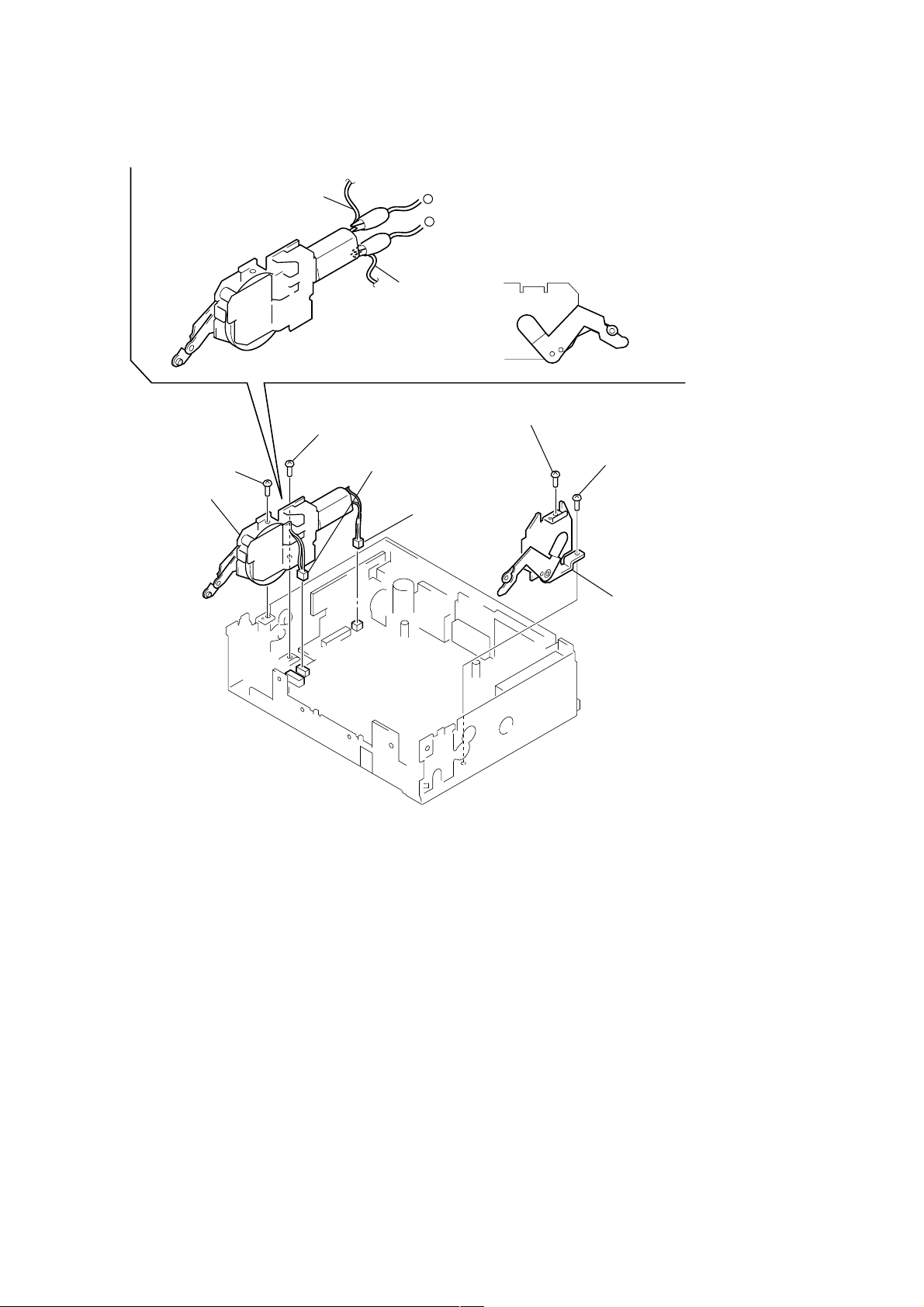
MOTOR BLOCK ASS’Y, CAM (R) ASS’Y
2 screw
(PTT2.6 × 8)
3 motor block ass'y
2 screw
(PTT2.6 × 6)
4 screw
1 connector
(CN602)
(PTT2.6 × 8)
4 screw
(PTT2.6 × 6)
5 cam (R) ass’
16

SUB PANEL (XR) SUB ASS’Y
)
2 screw
(PTT2.6 × 6)
3 sub panel (XR) sub ass'y
1 flexible board
(CN601)
2 two screws
(PTT2.6 × 6)
2 screw
(PTT2.6 × 6)
MAIN BOARD
1 two screws
(PTT2.6 × 6)
1 screw
(PTT2.6 × 6
2 three ground screws
3 main board
17

HEAT SINK
2 cord (with connector) (ANT)
6 three screws
(PTT2.6 × 8)
6 two screws
(PTT2.6 × 12)
5 cord (with connector) (SUB OUT)
1 connector
(CN100)
4 screw
(PTT2.6 × 6)
3 connector
(CN200)
6 two screws
(PTT2.6 × 8)
7 heat sink
18

SECTION 4
Note: Follow the assembly procedure in the numerical order given.
4-1. FRONT PANEL MACHINERY
MOTOR BLOCK ASS’Y
2 stop ring
1 cam (L)
hole
6 washer (M)
ASSEMBLY
7 bracket (motor) ass'y
5 gear (C)
4 gear (B)
concave portion
Note: When installing cam (L), adjust the hole and concave portion.
3 gear (A)
8 two screws
CAM (R) ASS’Y
2 stop ring
(PTT2.6 × 6)
switch
6 washer (M)
Set bracket (motor) ass’y
to be at the position in the
figure.
8 screw
(B2.6 × 6)
1 cam (R)
hole
concave portion
Note: When installing cam (R), adjust the hole and concave portion.
19
CAM (R) ASS’Y, MOTOR BLOCK ASS’Y
y
8 screw
(PTT2.6 × 8)
6 motor block ass'y
gray wiring
8 screw
(PTT2.6 × 6)
–
+
violet wiring
7 connector
(CN602)
7 connector
1 Supply the power to the motor.
Voltage : 9V
Violet wiring : MOTOR –
Gray wiring : MOTOR +
2 Motor stops at full open position.
full open position
4 screw
(PTT2.6 × 8)
4 screw
(PTT2.6 × 6)
(CN501)
3 cam (R) ass'
20
 Loading...