

Page 1

XM-D400P5
SERVICE MANUAL
Ver 1.1 2004. 03
SPECIFICATIONS
AUDIO POWER SPECIFICATIONS (US MODEL)
POWER OUTPUT AND TOTAL HARMONIC DISTORTION
200 watts minimum continuous average power into 4 ohms,
20 Hz to 300 Hz with no more than 0.2% total harmonic
distortion per Car Audio Ad Hoc Committee standards.
US Model
Canadian Model
AEP Model
UK Model
E Model
Other Specifications
Circuit system Class D Technology
Inputs RCA pin jacks
Outputs Speaker terminals
Suitable speaker impedance
Maximum outputs 400 W (at 4 Ω)
Rated outputs (supply voltage at 14.4 V)
Frequency response 5 Hz – 300 Hz ( dB)
Harmonic distortion 0.06% or less (at 100 Hz, 4 Ω)
Input level adjustment range
Pulse power supply
High level input connector
Through out pin jacks
2 – 8 Ω
800 W (at 2 Ω)
200 W (20 Hz – 300 Hz, 0.2% THD, at 4 Ω)
400 W (20 Hz – 300 Hz, 0.6% THD, at 2 Ω)
0.3 – 6.0 V (RCA pin jacks)
1.2 – 12.0 V (High level input)
+0.5
–3
Low-pass filter 50 – 300 Hz, –12 dB/oct
Low boost 0 – 10 dB (40 Hz)
Power requirements 12 V DC car battery
Power supply voltage 10.5 – 16 V
Current drain at rated output : 62 A (at 2 Ω)
Dimensions Approx. 295 × 57 × 290 mm
Mass Approx. 2.8 kg (6 lb. 3 oz.) not incl. accessories
Supplied accessories Mounting screws (5)
Design and specifications are subject to change without
notice.
Notes on Chip Component Replacement
• Never reuse a disconnected chip component.
• Notice that the minus side of a tantalum capacitor may be
damaged by heat.
(negative ground)
Remote input : 2 mA
5/8 × 2 1/4 × 11 1/2 in.) (w/h/d) not incl.
(11
projecting parts and controls
High level input cord (1)
Protection cap (1)
9-877-038-02
2004C04-1
© 2004. 03
MONAURAL POWER AMPLIFIER
Sony Corporation
e Vehicle Company
Published by Sony Engineering Corporation
1
Page 2

XM-D400P5
TABLE OF CONTENTS
1. GENERAL
Location and Function of Controls.......................................... 3
Connections ............................................................................. 4
2. DISASSEMBLY
2-1. Bottom Plate ........................................................................ 6
2-2. Main Board Section ............................................................. 7
2-3. Disassembly and Assembly of Ornamental Plate ................ 7
2-4. Main Board .......................................................................... 8
2-5. LED Board........................................................................... 8
3. DIAGRAMS
3-1. IC Block Diagram................................................................ 9
3-2. Printed Wiring Boards –Main Section (1/2)– .................... 10
3-3. Printed Wiring Boards –Main Section (2/2)– .................... 11
3-4. Schematic Diagram –Main Section (1/2)– ........................ 12
3-5. Schematic Diagram –Main Section (2/2)– ........................ 13
4. EXPLODED VIEWS
4-1. Heat Sink (Main) Section .................................................. 15
4-2. Main Board Section ........................................................... 16
5. ELECTRICAL PARTS LIST.........................................17
2
Page 3

SECTION 1
k
GENERAL
XM-D400P5
This section is extracted
from instruction manual.
Location and Function of Controls
1 POWER/PROTECTOR indicator
Lights up in green during operation.
When the PROTECTOR is activated the indicator will change from green
to red.
When the PROTECTOR is activated refer to the TroubleShooting Guide.
2 Cut-off frequency adjustment control
Sets the cut-off frequency (50 – 300 Hz) for the low-pass filters.
3 LOW BOOST level control
Turn this control to boost the frequencies around 40 Hz to a maximum of
10 dB.
4 LEVEL adjustment control
The input level can be adjusted with this control. Turn it in the clockwise
direction when the output level of the car audio unit seems low.
Low boost/
Amplification de basses fréquences
dB dB
10
0
10
40 100 1k
Frequency/Fréquence
Circuit Diagram/
Schéma du circuit
INPUT
THROUGH
OUT
Emplacement et fonction des commandes
LPF
70
50
POWER/PROTECTOR
LOW BOOST
(40Hz)
100
0+10dB
300Hz
LEVEL
2
4
0.5
0.3V
6
1 Indicateur POWER/PROTECTOR
S’allume en vert en cours de fonctionnement.
Lorsque PROTECTOR est activé, le voyant passe du vert au rouge.
Lorsque PROTECTOR est activé, reportez-vous au guide de dépannage.
2 Commandes de réglage de la fréquence de coupure
Règle la fréquence de coupure (50 – 300 Hz) pour les filtres passe-bas.
3 Commande de niveau LOW BOOST
Tournez cette commande pour amplifier les fréquences autour de 40 Hz à un
maximum de 10 dB.
4 Commande de réglage LEVEL
Le niveau d ’entrée peut se régler avec cette commande. Tournez cette
commande dans le sens des aiguilles d’une montre lorsque le niveau de sortie
de l’autoradio semble faible.
Low Pass Filter/
Filtre passe-bas
10
0
-10
-20
-30
-40
-50
-60
Hz
Lch
Rch
Lch
Rch
Buffer
LPF
LEVEL
10 100 1k 2
Frequency/Fréquence
LOW BOOST
LOW PASS
300Hz
100Hz
50Hz
Hz
Power
AMP
3
Page 4
XM-D400P5
Connections
Caution
• Before making any connections, disconnect
the ground terminal of the car battery to avoid
short circuits.
• Be sure to use speakers with an adequate
power rating. If you use small capacity
speakers, they may be damaged.
• Do not connect the # terminal of the speaker
system to the car chassis, and do not connect
the # terminal of the right speaker with that
of the left speaker.
• Install the input and output cords away from
the power supply wire as running them close
together can generate some interference noise.
• This unit is a high powered amplifier.
Therefore, it may not perform to its full
potential if used with the speaker cords
supplied with the car.
• If your car is equipped with a computer
system for navigation or some other purpose,
do not to remove the ground wire from the
car battery. If you disconnect the wire, the
computer memory may be erased. To avoid
short circuits when making connections,
disconnect the +12 V power supply wire until
all the other wires have been connected.
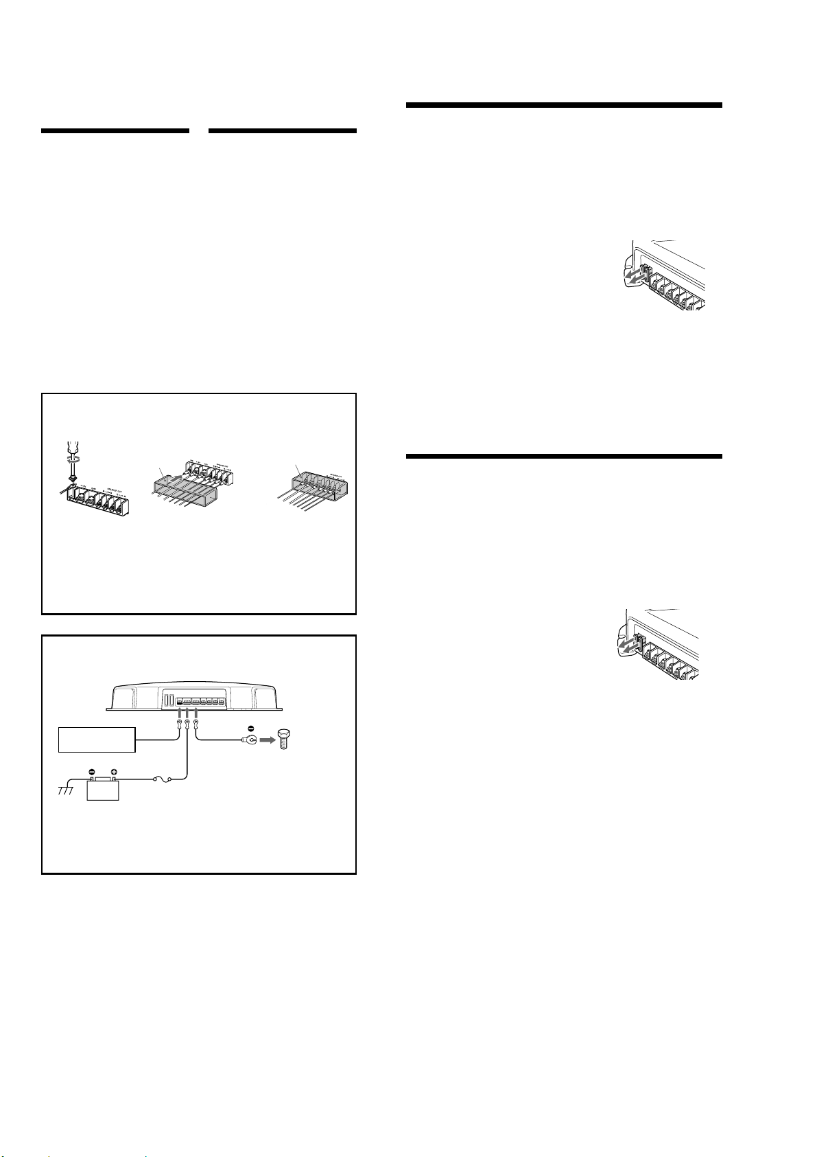
Make the terminal connections as illustrated below.
Effectuez les connexions des bornes comme illustré ci-dessous.
3
Connexions
Attention
• Avant d’effectuer les connexions, débranchez
la borne de masse de la batterie de voiture
pour éviter tout court-circuit.
• Veillez à utiliser des haut-parleurs de
puissance adéquate. Si vous utilisez des hautparleurs de faible capacité, ils risquent d’être
endommagés.
• Ne raccordez pas la borne # du système de
haut-parleurs à la carrosserie de la voiture ni
la borne # du haut-parleur droit avec celle du
haut-parleur gauche.
• Eloignez les câbles d’entrée et de sortie du
câble d’alimentation pour éviter les
interférences.
• Cet appareil est un amplificateur de haute
puissance. Il ne peut donc déployer sa pleine
puissance que si les câbles de haut-parleurs de
la voiture lui sont raccordés.
• Si votre voiture est équipée d’un système de
navigation ou d’un ordinateur de bord, ne
retirez pas le câble de terre de la batterie de la
voiture, sinon les données mémorisées seront
effacées. Pour éviter un court-circuit lorsque
vous effectuez les branchements, branchez le
câble d’alimentation +12 V après avoir
branché tous les autres câbles.
3
R
E
M
c
Pass the wires through the cap, connect
the wires, then cover the terminals with
the cap.
Note
When you tighten the screw, be careful not to
apply too much torque
the screw.
*
The torque value should be less than 1 N•m.
*
as doing so may damage
Power Connection Wires
Câbles d’alimentation
Remote output
Sortie de
télécommande
(REM OUT)
If you have the factory original or some other car audio unit without a remote output on the amplifier,
*
connect the remote input terminal (REMOTE) to the accessory power supply.
*
Si vous disposez du modèle d’origine ou d’un autre autoradio dont l’amplificateur ne comporte pas de
sortie de télécommande, raccordez la borne d’entrée de télécommande (REMOTE) à la prise
d’alimentation accessoires.
Notes on the power supply
•
Connect the +12 V power supply wire only after
all the other wires have been connected.
•
Be sure to connect the ground wire of the unit
securely to a metal point of the car. A loose
connection may cause a malfunction of the
amplifier.
•
Be sure to connect the remote control wire of the
car audio unit to the remote terminal.
• When using a car audio unit without a remote
output on the amplifier, connect the remote
input terminal (REMOTE) to the accessory power
supply.
•
Use the power supply wire with a fuse attached
(80 A).
•
Place the fuse in the power supply wire as close as
possible to the car battery.
•
Make sure that the wires to be connected to the
+
12 V and GND terminals of this unit are at least
4-Gauge (AWG-4) or have a sectional area of
more than 22.0 mm
*
*
Car audio unit
Autoradio
+12 V car battery
Batterie de voiture +12 V
2
.
Fuse (80 A)
Fusible (80 A)
Faites passer les câbles par le cache,
raccordez les câbles, puis recouvrez les
bornes avec le cache.
Remarque
Lorsque vous vissez la vis, faites attention à ne
pas appliquer une trop grande force
pourrait endommager la vis.
Le couple de torsion doit être inférieur à 1 N•m.
*
to a metal point
of the car
vers une partie
métallique de la
carrosserie
Remarques sur l’alimentation électrique
•
Raccordez le câble d’alimentation +12 V
uniquement après avoir réalisé toutes les autres
connexions.
•
Raccordez correctement le câble de masse à une
partie métallique de la voiture. Une connexion
lâche peut provoquer un dysfonctionnement de
l’amplificateur.
•
Veillez à raccorder le fil de télécommande de
l’autoradio à la borne de télécommande.
•
Si vous utilisez un l’autoradio dont l’amplificateur
ne comporte pas de sortie de télécommande,
raccordez la borne d’entrée de la télécommande
(REMOTE) à la prise d’alimentation accessoires.
•
Utilisez un câble d’alimentation muni d’un fusible
(80 A).
•
Fixez le câble d’alimentation le plus près possible
de la batterie de voiture.
•
Assurez-vous que les câbles à raccorder aux
bornes +12V et GND de cet appareil sont d’un
calibre d’au moins 4 (AWG-4) ou d’une section
supérieure à 22, 0 mm
2
.
+
1
2
V
GN
*
, car cela
Precautions
• This unit is designed for negative ground 12 V
DC operation only.
•
Use speakers with suitable impedance.
—2 to 8 Ω.
• Do not connect any active speakers (with built-in
amplifiers) to the speaker terminals of the unit.
Doing so may damage the active speakers.
•Avoid installing the unit in areas subject to:
—high temperatures such as from direct
sunlight or hot air from the heater
—rain or moisture
—dust or dirt
• If your car is parked in direct sunlight and there
is a considerable rise in temperature inside the
car, allow the unit to cool down before use.
• When installing the unit horizontally, be sure not
to cover the fins with the floor carpet etc.
• If this unit is placed too close to the car audio
unit or antenna, interference may occur. In this
case, relocate the amplifier away from the car
audio unit or antenna.
• If no power is being supplied to the car audio
unit, check the connections.
• This power amplifier employs a protection
circuit * to protect the transistors and speakers if
the amplifier malfunctions. Do not attempt to test
the protection circuits by covering the heat sink
or connecting improper loads.
• Do not use the unit on a weak battery as its
optimum performance depends on a good power
supply.
•For safety reasons, keep your car audio volume
moderate so that you can still hear sounds
outside your car.
D
Précautions
•Cet appareil est conçu pour fonctionner sur du
courant continu 12 V à masse négative.
•Utilisez des haut-parleurs d’une impédance
appropriée.
—2 à 8 Ω.
•Ne raccordez pas de haut-parleurs actifs (avec
amplificateurs intégrés) aux bornes de hautparleurs de cet appareil. Cette opération pourrait
endommager les haut-parleurs actifs.
•N’installez pas l’appareil à un endroit exposé à :
—de hautes températures comme sous le
rayonnement direct du soleil ou près d’un
conduit de chauffage
— la pluie ou à l’humidité
—de la poussière ou à des saletés
•Si votre voiture est garée en plein soleil et que la
température à l’intérieur de l’habitacle a
considérablement augmenté, laissez refroidir
l’appareil avant de l’utiliser.
• Lorsque vous installez l’appareil à l’horizontale,
veillez à ne pas recouvrir la grille d’aération avec
le tapis, etc.
•Si cet appareil est placé trop près de l’autoradio
ou de l’antenne, il se peut que des interférences
se produisent. Dans ce cas, éloignez
l’amplificateur de l’autoradio ou de l’antenne.
•Si l’autoradio n’est pas alimenté, vérifiez les
branchements.
• Cet amplificateur de puissance utilise un circuit
de protection * visant à protéger les transistors et
les haut-parleurs en cas de dysfonctionnement de
l’amplificateur. Ne tentez pas de tester les
circuits de protection en couvrant l’accumulateur
de chaleur ou en branchant des charges
inadéquates.
•N’utilisez pas cet appareil avec une batterie
faible car les performances optimales de
l’appareil dépendent d’une bonne alimentation
électrique.
• Pour des raisons de sécurité, gardez le volume de
votre installation audio de voiture à un niveau
permettant encore la perception des bruits
extérieurs.
Fuse Replacement
If the fuse blows, check the power connection and
replace all fuses. If the fuse blows again after
replacement, there may be an internal malfunction.
In such a case, consult your nearest Sony dealer.
Warning
When replacing the fuse, be sure to use one
matching the amperage stated above the fuse
holder. Never use a fuse with an amperage rating
exceeding the one supplied with the unit as this
could damage the unit.
∗
Protection circuit
This amplifier is provided with a protection circuit
that operates in the following cases:
— when the unit is overheated
— when a DC current is generated
— when the speaker terminals are short circuited.
The POWER/PROTECTOR indicator lights up in red
and the unit will shut down.
If this happens, turn off the connected equipment,
take out the cassette tape or disc, and determine
the cause of the malfunction. If the amplifier has
overheated, wait until the unit cools down before
use.
If you have any questions or problems concerning
your unit that are not covered in this manual,
please consult your nearest Sony dealer.
Remplacement du fusible
Si le fusible fond, vérifiez le branchement de
l’alimentation et remplacez tous les fusibles. Si le
fusible grille encore après ce remplacement, il est
possible qu’il y ait un dysfonctionnement interne.
Dans ce cas, adressez-vous à votre distributeur
Sony le plus proche.
Avertissement
Lors du remplacement du fusible, veillez à
respecter l’ampérage indiqué au-dessus du
logement du fusible. N’utilisez jamais un fusible
d’ampérage supérieur à celui fourni avec
l’appareil, car cela pourrait endommager
l’appareil.
*
Circuit de protection
Cet amplificateur est équipé d’un circuit de
protection qui s’active dans les cas suivants :
— en cas de surchauffe de l’appareil
— en cas de génération d’un courant continu
—lorsque les bornes de haut-parleurs sont court-
circuitées.
L’indicateur POWER/PROTECTOR s’allume en
rouge et l’appareil s’arrête.
Dans ce cas, éteignez tout équipement raccordé,
retirez la cassette ou le disque et déterminez la
cause du dysfonctionnement. Si l’amplificateur a
surchauffé, attendez que l’appareil refroidisse
avant de le réutiliser.
Si vous avez des questions ou des problèmes
concernant votre appareil qui ne sont pas abordés
dans ce mode d’emploi, adressez-vous à votre
distributeur Sony le plus proche.
4
Page 5

XM-D400P5
Input Connections
For details on the settings of switches and controls, refer to “Location and Function of Controls.”
Line Input Connection
1 or 2)
Connexion d’entrée de ligne
parleur 1 ou 2)
*
• You can connect either output terminal.
• The minimum resistance must be 2
Line Input Connection
Connexion d’entrée de ligne
parleur 4)
Car audio unit
Autoradio
LINE OUT
INPUT INPUT
(with Speaker Connection
(avec connexion de haut-
Car audio unit
Autoradio
LINE OUT*
*
•Peu importe la borne de sortie que vous raccordez.
Ω
in total.
• La résistance minimale doit être égale à 2
(with Speaker Connection 4)
(avec connexion de haut-
THROUGH OUT
AA
A
AA
Ω
au total.
CC
C
CC
Connexions d’entrée
Pour plus de détails sur les réglages des commutateurs et commandes, reportez-vous à “Emplacement
et fonction des commandes”.
Line Input Connection
Connexion d’entrée de ligne
parleur 3)
• You can connect either output terminal.
*
• The minimum resistance must be 2
High Level Input Connection
1)
Connexion à l’entrée de haut niveau
de haut-parleur 1)
Left speaker
Haut-parleur gauche
Right speaker
Haut-parleur droit
(with Speaker Connection 3)
(avec connexion de haut-
Left channel
Canal gauche
*
•Peu importe la borne de sortie que vous raccordez.
Ω
2
in total.
• La résistance minimale doit être égale à 2
(with Speaker Connection
Car audio unit
Autoradio
LINE OUT*
Right channel
Canal droit
(avec connexion
Car audio unit
Autoradio
Ω
BB
B
BB
au total.
DD
D
DD
When you connect amplifiers using with the
THROUGH OUT pin jacks, it allows you to connect
up to a maximum of three.
Otherwise the necessary output levels can not be
obtained, and your car audio may be damaged.
Use the THROUGH OUT terminal when you install
more amplifiers. The signals are output as they
were input. (LOW BOOST do not work.)
Lorsque vous raccordez des amplificateurs à l’aide
des prises à broches THROUGH OUT, vous pouvez
raccorder jusqu’à 3 amplificateurs au maximum.
Sinon les niveaux de sortie requis ne peuvent pas
être obtenus et votre autoradio risque d’être
endommagé.
Utilisez la borne THROUGH OUT lorsque vous
installez plusieurs amplificateurs. Les signaux sont
sortis comme ils sont entrés. (LOW BOOST ne
fonctionnent pas.)
Speaker Connections
For details on the settings of switches and controls, refer to “Location and Function of Controls.”
1-Speaker System
Système à 1 haut-parleur
D)
Subwoofer (min. TOTAL 2 Ω)
Caisson de grave (min. TOTAL 2 Ω)
1-Speaker System
Système à 1 haut-parleur
(with Input Connection A or D)
(avec connexion d’entrée A ou
(with Input Connection B)
(avec connexion d’entrée B)
11
1
11
33
3
33
Grey/Black
striped
Rayé gris/noir
Grey
Gris
White/Black
striped
Rayé blanc/noir
White
Blanc
Raccordement de haut-parleurs
Pour plus de détails sur les réglages des commutateurs et commandes, reportez-vous à “Emplacement
et fonction des commandes”.
2-Speaker System
Système à 2 haut-parleurs
Subwoofer*
(min. TOTAL 4 Ω)
Caisson de grave*
(min. TOTAL 4 Ω)
*
When you use two terminals with speakers, each
of terminal resistance is 4
(Two terminals are connected with each other in
the unit.)
2-Way System
Système à 2 voies
(with Input Connection A)
Ω
at a minimum.
(with Input Connection C)
(avec connexion d’entrée C)
(avec connexion d’entrée A)
*
Lorsque vous utilisez deux bor nes avec des hautparleurs, la résistance de chaque borne doit au
moins être égale à 4
(Les deux bornes sont raccordées l’une à l’autre
dans l’appareil.)
Ω
.
Subwoofer*
(min. TOTAL 4 Ω)
Caisson de grave*
(min. TOTAL 4 Ω)
22
2
22
44
4
44
Left subwoofer (min. TOTAL 2 Ω)
Caisson de grave gauche (min. TOTAL 2 Ω)
Right subwoofer
(min. TOTAL 2 Ω)
Caisson de grave droit
(min. TOTAL 2 Ω)
Subwoofer (min. TOTAL 2 Ω)
Caisson de grave (min. TOTAL 2 Ω)
Full range speakers
Haut-parleurs à large bande
5
Page 6
XM-D400P5
SECTION 2
DISASSEMBLY
Note : This set can be disassemble according to the following sequence.
SET
2-1. BOTTOM PLATE
(Page 6)
2-2. MAIN BOARD SECTION
(Page 7)
2-4. MAIN BOARD
(Page 8)
Note : Follow the disassembly procedure in the numerical order given.
2-5. LED BOARD
(Page 8)
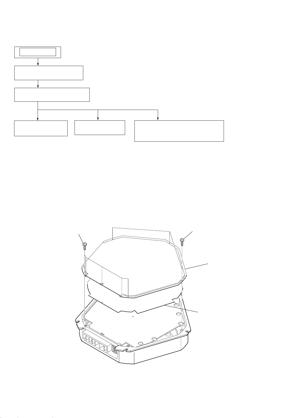
2-1. BOTTOM PLATE
1
P 3x6
2-3. DISASSMBLY AND ASSEMBLY
OF ORNAMENTAL PLATE
(Page 7)
2
P 3x6
3
bottom plate
4
insulating sheet
6
Page 7

2-2. MAIN BOARD SECTION
heat sink (main)
3
BTP 3x14
4
BTP 3x14
5
BTP 3x14
1
P 3x8
7
CNT2
6
MAIN board section
2
P 3x6
XM-D400P5
2-3. DISASSEMBLY AND ASSEMBLY OF ORNAMENTAL PLATE
At disassembly:
heat sink (main)
ornamental plate
cut
At assembly:
heat sink (main)
welding
ornamental plate
7
Page 8

XM-D400P5
)
2-4. MAIN BOARD
1
P 3x8
2
P 3x8
4
MAIN board
2-5. LED BOARD
3
panel (front)
1
P 3x6
2
LED board
heat sink (main
8
Page 9

SECTION 3
DIAGRAMS
XM-D400P5
THIS NOTE IS COMMON FOR PRINTED WIRING BOARDS
AND SCHEMATIC DIAGRAMS.
(In addition to this, the necessary note is
printed in each block.)
for schematic diagram:
Note:
• All capacitors are in µF unless otherwise noted. pF: µµF
50 WV or less are not indicated except for electrolytics
and tantalums.
• All resistors are in Ω and 1/
specified.
4
W or less unless otherwise
•%: indicates tolerance.
• 2 : nonflammable resistor.
Note:
The components identified by mark 0 or dotted
line with mark 0 are critical for safety.
Replace only with part
number specified.
Note:
Les composants identifiés par
une marque 0 sont critiques
pour la sécurité.
Ne les remplacer que par une
piéce portant le numéro
spécifié.
• A : B+ Line.
• B : B– Line.
•Total current is measured with no-signal condition.
•Power voltage is dc 14.4V and fed with regulated dc power
supply from +12V and REM terminals.
•Voltage is dc with respect to ground under no-signal
condition.
•Voltages are taken with a VOM (Input impedance 10 MΩ).
Voltage variations may be noted due to normal production tolerances.
•Waveforms are taken with a oscilloscope.
Voltage variations may be noted due to normal production tolerances.
• Circled numbers refer to waveforms.
• Signal path.
F : AUDIO
3-1. IC BLOCK DIAGRAM
IC6 TL494CN
NON
INV
16 15 14 13 12 11 10 9
ERROR
ERROR
1 2 3 4 5 6 7 8
+IN
VREF
0.1V
-IN
COMP EN
TIME
OUT
REF 5V
VCC
OSC
CT
C2E1E2
RT
GND
C1
for printed wiring boards:
Note:
• X : parts extracted from the component side.
• : Pattern from the side which enables seeing.
(The other layer’s patterns are not indicated.)
Caution:
Pattern face side: P arts on the pattern face side seen from the
(Side B) pattern face are indicated.
Parts face side: Parts on the parts face side seen from the
(Side A) parts face are indicated.
99
Page 10

XM-D400P5
3-2. PRINTED WIRING BOARDS — MAIN SECTION (1/2) — • Refer to page 9 for Common Note on Printed Wiring Boards.
• Semiconductor
Location (Side A)
Ref. No. Location
D3 F-6
D5 F-6
D9 E-4
D11 G-4
D17 G-6
IC1 F-3
IC2 F-3
IC3 E-3
IC4 E-2
IC5 G-4
IC7 F-5
IC8 H-6
Q5 E-4
Q6 E-4
Q7 G-5
Q8 F-5
Q9 F-5
Q10 H-6
Q11 F-6
Q13 D-8
Q16 F-6
Q17 H-6
Q34 H-6
Q35 H-6
Q36 H-6
Q39 G-6
Q40 F-6
Q41 G-6
Q42 G-6
Q43 G-6
Q44 F-6
Q45 G-6
Q46 D-2
LED BOARD (SIDE A)
RG
LED2
LED3
POWER/PROTECTOR
11
1-688-332-
(11)
RG2
RG3
THR1
RG4
RG5
RG1
RG6
23456789101112
1
MAIN BOARD (SIDE A)
A
THR3
C33
R100
R88
R90
C44
R92
R95
R94
C37
R89
C32
R91
C34
R71
R86
R166
R58
Q17
Q35
R132
R125
C43
Q45
R133
C40
BCE
BCE
BCE
R138
C10
Q11
R151
R150
R181
R82
ECB
R96
Q43
R120 R128
R126
85
IC8
R137
14
C7 R130
R127 R129
R131
D3
KAK
R81
R54
C35
ECB
R182
Q41
Q44
BCE
R67
R68
C31
R77
D5
AKA
R80
14 8
1
R55
C36
ECB
R149
Q39
R154
ECB
Q42
Q36
R105
BCE
R173
R178
R172
C11
Q34
BCE
C41
R69
R70
R103
R106
R180
C45
IC7
Q10
R85
R78
C6 R79
7
R104
Q8
R75R74
ECB
Q9
ECB
Q7
ECB
R76
R186
R184 R183
R185
Q16
BCE
R170
R72
ECB
Q40
D17
AKA
R162
C38
BCE
R160
R97
BCE
R108
R135
R107
R117
R118
R121
R122
R114
R115
R113
R65
148
CF1
C13
R143
R123
C8
R134
IC1
C9
R164 C28
R163R6C29
R17
R116
R119
C5
C22
R158
5
R1
R157
R7 C27
C30
R28
R3
R4
RS1
R10
1-688-331-
148
R27 RS6
148
RS2
C56R63
C1C58
C2
R155
R11 C55
C50 C53
C51
C52
IC3
R35
IC2
C12
C57
C3
148
IC4
5
5
11
(11)
ECB
R174
Q46
5
R29
C59
R25
R24
R23
R15
R16
R13
MC1
R12
R5
R169
R14
R20
R112
R19
R110
D9
R109
R111
Q6
BCE
BCE
Q5
C42
R66
R64
R171
C21
R159
R2
R156
R56
R60
R53
R136
C39
R57
C14
148
IC5
C15
R59
C20
R50
R51
D11
5
R43
R52
R61
R62
R18
R99
R102
R141
R142
R93
R139
R140
Q13
BCE
R83
C19
C16
B
C
D
E
F
G
H
I
10 10
J
Page 11

3-3. PRINTED WIRING BOARDS — MAIN SECTION (2/2) — • Refer to page 9 for Common Note on Printed Wiring Boards.
XM-D400P5
A
B
C
D
E
F
G
H
1
LEVEL
VR1
VR2
LOW
BOOST
(40Hz)
JK1
VR3
LPF
OUTPUT
(THROUGH)
INPUT
HIGH LEVEL INPUT
23456789101112
MAIN BOARD (SIDE B)
MC14
MC8
EC17
MC6
-2
-1
-2
-1
-2
-1
-3
L
-4
R
L
-2
R
-4 -2
RL
-3 -1
CNT1
EC40
MC13
S D G
FET8
R175
S D G
FET7
S D G
FET9
Q28
Q30
E B C
E B C
Q29
E B C
EC52
EC8
EC6
EC10
Q20
ZD3
E B C
EC61
E B C
E B C
E B C
MC11
EC13
EC11
MC9
MC10
EC9
EC7
Q31
Q18
E C B
EC28
Q3
D2
MC25
Q27
EC14
R145
D14
D13
R124
ZD5
D16
D15
EC29
C17
EC16
BD1
BD2
BD3
BD4
BD5
S D G
FET10
Q23
E B C
Q26
Q33
EC51
-2
-4
E B C
E B C
E C B
EC1
EC54
EC55
EC2
Q25
EC56
D8
E B C
Q24
E C B
Q4
EC5
Q21
E C B
EC57
EC3EC4
ZD4
E B C
Q19
3
241
PTC2
E B C
E B C
Q22
Q32
MC7
MC5
MC4
-1
-1
-3
R176
R177
R168
R144
MC21
EC12
EC18
MC22
BD6
EC38
EC33
EC30
LF2
THR2
13
CNT2
2
1
MC28
ORG
PTC1
EC39EC37
D20
D19
EC31
EC32
T1
EC15
EC50
PT1
1
16
MC26
C18
MC12
IC6
E C B
E C B
8
9
Q12
Q38
FET6
Q37
E C B
EC23
S D G
EC24
EC27
EC26
EC25
FET2
S D G
FET5
FET4
G D S
FET3
G D S
G D S
LED BOARD (SIDE B)
R101
BLK
YEL
MC15
3
4
EC22
LF1
MC18
MC20
FET1
G D S
CON2
13
11
(11)
1-688-332-
YEL
BLK
ORG
• Semiconductor
Location (Side B)
Ref. No. Location
D2 D-4
D8 E-3
D13 D-5
D14 D-4
D15 F-4
D16 F-4
D19 B-8
D20 B-7
FET1 G-9
FET2 F-9
FET3 E-9
FET4 E-9
FET5 C-9
FET6 C-9
FET7 B-4
FET8 B-5
FET9 C-4
FET10 C-3
IC6 D-8
PTC1 H-6
PTC2 E-4
Q1 I-3
Q2 I-4
Q3 H-4
Q4 H-3
Q12 D-8
Q18 D-4
Q19 D-4
Q20 D-4
Q21 D-3
Q22 D-3
Q23 C-3
Q24 D-3
Q25 D-3
Q26 D-3
Q27 C-4
Q28 C-4
Q29 D-4
Q30 C-4
Q31 D-4
Q32 D-3
Q33 E-3
Q37 D-9
Q38 C-8
ZD1 H-3
ZD2 H-3
ZD3 G-4
ZD4 H-3
ZD5 E-4
ZD1
E B C
I
ZD2
E B C
Q1
Q2
C23
EC21
MC24
EC19
MC23
EC58
1-688-331-
C46
MC27
11
(11)
J
(L+R) (L+R)
SPEAKER OUT
+12VGND
TER1
REM
FUSE1
30A
FUSE2
30A
11 11
Page 12

XM-D400P5
3-4. SCHEMATIC DIAGRAM — MAIN SECTION (1/2) — • Refer to page 9 for Common Note on Schematic Diagram.
CNT1
R10
R11
C50
C51C52
JK1
EC56
R155
C57
C3 R63
C58 C56
R6C30
R163
C29
R164
C28
R7
C27
C53
EC1
R1
EC54
C1
C2
R156
C55
EC55
R157
R2
EC2
C12
IC1(1/2)
R159
C21
C5
C13
C9
IC1(2/2)
R158
C22
R3
RS1
IC2(1/2)
R4
MC6
RS2
VR3-1
VR3-2
R20
IC2(2/2)
R23
MC5
R25
MC4
R24
MC7
IC3(2/2)
VR1
R169
R136
R59
C17
IC5(1/2)
C39
R57
C20
(Page 13)
IC3(1/2)
R29
R5
R28
R35
C59
RS6
R27
R12
IC4(2/2)
MC1
R13
EC17
VR2
R14
EC3
EC4
Q46
MC8
R15
R16 R174
Q1
R17
ZD1
ZD2
R18
Q2
EC51
R43
R52
EC9
C14
EC5
EC6
EC10
C15
D11
MC10
ZD3
ZD4
IC5(2/2)
R50
EC52
Q3
R62
EC7
EC8
R61
Q4
R53
MC9
R51
R60
D16
EC28
EC29
D15
LED3
LED2
CON2
CNT2
D3
THR3THR2THR1
Q7
R74R75
Q40
R72
Q39
R55R54
Q8
R149
Q42Q43
C45
C35 C36
Q11
R150R151
Q45
R96
Q41
D17
R182
R162
R160
C38
R82
R81 R154
R180R181
D5
C6
R68
Q9
EC12
R78
R70R76
R171
R170
R79
R69
IC7
R85
R103
R65
R104
R106
C42
R66
EC11
R64
6
Q
R80
R77
C31
Q5
R67
Q16
Q44
12 12
Page 13

3-5. SCHEMATIC DIAGRAM — MAIN SECTION (2/2) — • Refer to page 9 for Common Note on Schematic Diagram and IC Block Diagram.
EC61
(Page 12)
R119
R112
R115R114
R19
R113
Q21
D2
PTC2
R117
Q31
R108
PTC1
R128
R145
C40
Q36
R97 ZD5
D13
D14
EC37 EC38 EC39 EC40
D9
MC25
R110
Q32
Q18
EC57
R120
MC28
MC11
Q19
R111
CF1
R135
EC14
R56
R109
Q33
C8
R134
R123
D8
R133
Q20
Q23Q24
R143
Q22
R116
Q28
Q29Q30
R118
R137
R132
Q17
R138R125
C41
R107
R131
R129
Q35
R127
D19
MC13
R121
Q25Q26
Q27
R122
R144 R168 R175 R176 R177
EC13
C7
R130
FET9 FET10
FET7
IC8
PT1
MC14
LF2
R101
R186
FET8
R124
R126
R185
FET1 FET2 FET3
RG6 RG5 RG4
BD1
BD2
BD3
EC18
MC21 MC22 MC23 MC24
EC16
C11
Q34
R105
BD4
BD5
BD6
R173R178
Q10
EC58
R172
R184
R183
EC21
EC19
C23
Q12
R83
Q13
R71
FUSE1
LF1
C19 C16
FUSE2
MC27
XM-D400P5
TER1
C46
R166R86
C34
MC20
C43
R91
R88
EC50
R93
C10
IC6
IC B/D
EC30 EC31 EC32 EC33
R140
R142
R139
R141
Q38
Q37
R102
R99
C33
D20
EC15
R100
MC26
R58
FET4 FET5 FET6
MC15
RG3 RG2 RG1
T1
EC27
EC26
EC25
EC24
EC23
EC22
MC18
• Waveform
1V/DIV, 5µsec/DIV
1
3.4Vp-p
15µsec
IC6
5
R95
R94
C32
C37
C18
R89
R90
R92
C44
C12
M
13 13
Page 14

XM-D400P5
MEMO
14 14
Page 15
SECTION 4
EXPLODED VIEWS
XM-D400P5
NOTE:
• The mechanical parts with no reference
number in the exploded views are not supplied.
• Items marked “*” are not stocked since
they are seldom required for routine service.
Some delay should be anticipated
when ordering these items.
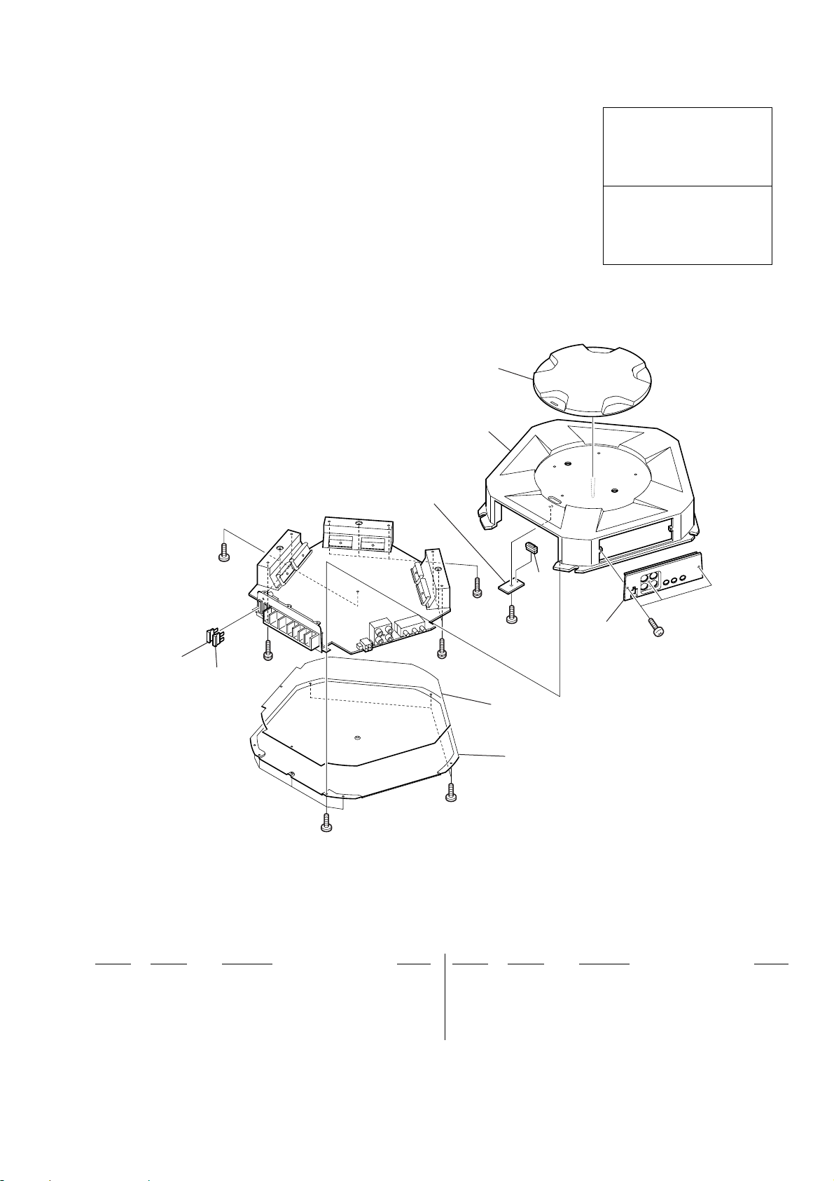
4-1. HEAT SINK (MAIN) SECTION
• Color Indication of Appearance Parts
Example :
KNOB, BALANCE (WHITE) ... (RED)
R
Parts Color Cabinet’s Color
• Accessories are given in the last of this parts list.
R
1
2
not supplied
(LED board)
The components identified by
mark 0 or dotted line with mark
0 are critical for safety.
Replace only with part number
specified.
Les composants identifiés par une
marque 0 sont critiques pour
la sécurité.
Ne les remplacer que par une piéce
portant le numéro spécifié.
#1
FUSE2
13-253-078-01 PLATE, ORNAMENTAL
23-253-077-01 HEAT SINK (MAIN)
33-253-079-01 PLATE, LIGHT GUIDE
43-253-081-01 PANEL (REAR)
53-253-082-01 PLATE, BOTTOM
FUSE1
#2
#1
3
#2
#1
#2
not supplied
4
#3
5
#1
Ref. No. Part No. Description RemarkRef. No. Part No. Description Remark
0 FUSE1 1-532-947-11 FUSE (BLADE TYPE) (AUTO FUSE) (30A)
0 FUSE2 1-532-947-11 FUSE (BLADE TYPE) (AUTO FUSE) (30A)
#1 7-685-645-79 SCREW +P 3X6 TYPE2 NON-SLIT
#2 7-685-549-19 SCREW +BTP 3X14 TYPE2 N-S
#3 7-685-646-79 SCREW +P 3X8 TYPE2 NON-SLIT
15
Page 16

XM-D400P5
4-2. MAIN BOARD SECTION
52
53
#3
53
57
59
51
not supplied
58
#3
54
#1
56
55
55
55
54
not supplied
55
#1
#1
54
not supplied
53
55
56
51 3-253-080-01 PANEL (FRONT)
52 A-3274-811-A MAIN BOARD, COMPLETE
53 3-253-084-01 HEAT SINK (SUB)
54 3-253-062-01 PLATE, RETAINER
55 3-225-183-11 SCREW (+PSW.TT.3XL)
56 3-254-946-01 PLATE, RETAINER
16
Ref. No. Part No. Description RemarkRef. No. Part No. Description Remark
57 3-912-431-01 SCREW (+–P)
58 3-912-432-01 SCREW (+–B)
59 3-253-537-01 SCREW (M5X11)
#1 7-685-645-79 SCREW +P 3X6 TYPE2 NON-SLIT
#3 7-685-646-79 SCREW +P 3X8 TYPE2 NON-SLIT
Page 17

XM-D400P5
SECTION 5
ELECTRICAL PARTS LIST
NOTE:
• Due to standardization, replacements in
the parts list may be different from the
parts specified in the diagrams or the
components used on the set.
• RESISTORS
All resistors are in ohms.
METAL:Metal-film resistor.
METAL OXIDE: Metal oxide-film resistor.
F:nonflammable
Ref. No. Part No. Description Remark Ref. No. Part No. Description Remark
LED BOARD
**********
< DIODE >
LED2 8-719-060-99 LED SML-210MT-T86 (POWER/PROTECTOR
LED3 8-719-066-99 LED SML-210VT-T86 (POWER/PROTECTOR
*************************************************************
A-3274-811-A MAIN BOARD, COMPLETE
*********************
3-253-062-01 PLATE, RETAINER
3-253-084-01 HEAT SINK (SUB)
< FERRITE BEAD >
BD1 1-410-396-41 INDUCTOR, FERRITE BEAD 0.45uH
BD2 1-410-396-41 INDUCTOR, FERRITE BEAD 0.45uH
BD3 1-410-396-41 INDUCTOR, FERRITE BEAD 0.45uH
BD4 1-410-396-41 INDUCTOR, FERRITE BEAD 0.45uH
BD5 1-410-396-41 INDUCTOR, FERRITE BEAD 0.45uH
BD6 1-410-396-41 INDUCTOR, FERRITE BEAD 0.45uH
< CAPACITOR >
C1 1-163-275-11 CERAMIC CHIP 0.001uF 5% 50V
C2 1-163-275-11 CERAMIC CHIP 0.001uF 5% 50V
C3 1-164-004-11 CERAMIC CHIP 0.1uF 10% 25V
C5 1-164-004-11 CERAMIC CHIP 0.1uF 10% 25V
C6 1-164-004-11 CERAMIC CHIP 0.1uF 10% 25V
C7 1-164-005-11 CERAMIC CHIP 0.47uF 25V
C8 1-163-017-00 CERAMIC CHIP 0.0047uF 5% 50V
C9 1-164-004-11 CERAMIC CHIP 0.1uF 10% 25V
C10 1-164-004-11 CERAMIC CHIP 0.1uF 10% 25V
C11 1-164-005-11 CERAMIC CHIP 0.47uF 25V
• Items marked “*” are not stocked since
they are seldom required for routine service.
Some delay should be anticipated
when ordering these items.
• SEMICONDUCTORS
In each case, u : µ, for example:
uA.. : µA.. uPA.. : µPA..
uPB.. : µPB.. uPC.. : µPC.. uPD.. : µPD..
• CAPACITORS
uF : µF
• COILS
uH : µH
C22 1-163-235-11 CERAMIC CHIP 22PF 5% 50V
C23 1-102-074-00 CERAMIC 0.001uF 10% 50V
C27 1-164-346-11 CERAMIC CHIP 1uF 16V
C28 1-164-346-11 CERAMIC CHIP 1uF 16V
C29 1-164-346-11 CERAMIC CHIP 1uF 16V
(POWER))
(PROTECTOR))
C30 1-164-346-11 CERAMIC CHIP 1uF 16V
C31 1-164-004-11 CERAMIC CHIP 0.1uF 10% 25V
C32 1-164-004-11 CERAMIC CHIP 0.1uF 10% 25V
C33 1-163-021-11 CERAMIC CHIP 0.01uF 10% 50V
C34 1-164-005-11 CERAMIC CHIP 0.47uF 25V
C35 1-164-004-11 CERAMIC CHIP 0.1uF 10% 25V
C36 1-164-005-11 CERAMIC CHIP 0.47uF 25V
C37 1-164-004-11 CERAMIC CHIP 0.1uF 10% 25V
C38 1-164-004-11 CERAMIC CHIP 0.1uF 10% 25V
C39 1-163-251-11 CERAMIC CHIP 100PF 5% 50V
C40 1-164-005-11 CERAMIC CHIP 0.47uF 25V
C41 1-164-004-11 CERAMIC CHIP 0.1uF 10% 25V
C42 1-164-004-11 CERAMIC CHIP 0.1uF 10% 25V
C43 1-164-004-11 CERAMIC CHIP 0.1uF 10% 25V
C44 1-163-275-11 CERAMIC CHIP 0.001uF 5% 50V
C45 1-164-004-11 CERAMIC CHIP 0.1uF 10% 25V
C46 1-102-129-00 CERAMIC 0.01uF 10% 50V
C50 1-163-275-11 CERAMIC CHIP 0.001uF 5% 50V
C51 1-163-275-11 CERAMIC CHIP 0.001uF 5% 50V
C52 1-163-275-11 CERAMIC CHIP 0.001uF 5% 50V
C53 1-163-275-11 CERAMIC CHIP 0.001uF 5% 50V
C55 1-163-275-11 CERAMIC CHIP 0.001uF 5% 50V
C56 1-163-275-11 CERAMIC CHIP 0.001uF 5% 50V
C57 1-163-275-11 CERAMIC CHIP 0.001uF 5% 50V
C58 1-163-275-11 CERAMIC CHIP 0.001uF 5% 50V
C59 1-163-251-11 CERAMIC CHIP 100PF 5% 50V
CF1 1-163-021-11 CERAMIC CHIP 0.01uF 10% 50V
The components identified by
mark 0 or dotted line with mark
0 are critical for safety.
Replace only with part number
specified.
Les composants identifiés par une
marque 0 sont critiques pour
la sécurité.
Ne les remplacer que par une piéce
portant le numéro spécifié.
When indicating parts by reference
number, please include the board.
< CONNECTOR >
LED MAIN
C12 1-164-004-11 CERAMIC CHIP 0.1uF 10% 25V
C13 1-163-275-11 CERAMIC CHIP 0.001uF 5% 50V
C14 1-164-005-11 CERAMIC CHIP 0.47uF 25V
C15 1-164-005-11 CERAMIC CHIP 0.47uF 25V
C16 1-163-275-11 CERAMIC CHIP 0.001uF 5% 50V
C17 1-117-219-11 CERAMIC 68PF 5% 1KV
C18 1-104-987-11 MYLAR 0.001uF 5% 100V
C19 1-163-275-11 CERAMIC CHIP 0.001uF 5% 50V
C20 1-163-275-11 CERAMIC CHIP 0.001uF 5% 50V
C21 1-163-235-11 CERAMIC CHIP 22PF 5% 50V
* CNT1 1-691-785-11 PIN, CONNECTOR (PC BOARD) 4P
(HIGH LEVEL INPUT)
* CNT2 1-569-596-11 PLUG, CONNECTOR (2.5mm) 3P
< DIODE >
D2 8-719-110-72 DIODE RD30ES-B2
D3 8-719-820-05 DIODE 1SS181
D5 8-719-801-78 DIODE 1SS184
D8 8-719-160-29 DIODE RD6.2F-B2
D9 8-719-800-76 DIODE 1SS226
17
Page 18

XM-D400P5
MAIN
Ref. No. Part No. Description Remark Ref. No. Part No. Description Remark
D11 8-719-800-76 DIODE 1SS226
D13 8-719-987-67 DIODE 11EFS2
D14 8-719-987-67 DIODE 11EFS2
D15 8-719-987-67 DIODE 11EFS2
D16 8-719-987-67 DIODE 11EFS2
FET2 8-729-056-77 FET RFP70N06
FET3 8-729-056-77 FET RFP70N06
FET4 8-729-056-77 FET RFP70N06
FET5 8-729-056-77 FET RFP70N06
FET6 8-729-056-77 FET RFP70N06
D17 8-719-801-78 DIODE 1SS184
D19 8-719-076-60 DIODE FCH20A15
D20 8-719-076-61 DIODE FRH20A15
< CAPACITOR >
EC1 1-128-582-11 ELECT 10uF 20% 63V
EC2 1-128-582-11 ELECT 10uF 20% 63V
EC3 1-126-965-11 ELECT 22uF 20% 50V
EC4 1-126-965-11 ELECT 22uF 20% 50V
EC5 1-126-965-11 ELECT 22uF 20% 50V
EC6 1-126-965-11 ELECT 22uF 20% 50V
EC7 1-126-965-11 ELECT 22uF 20% 50V
EC8 1-126-965-11 ELECT 22uF 20% 50V
EC9 1-104-666-11 ELECT 220uF 20% 25V
EC10 1-104-666-11 ELECT 220uF 20% 25V
EC11 1-128-582-11 ELECT 10uF 20% 63V
EC12 1-126-965-11 ELECT 22uF 20% 50V
EC13 1-126-965-11 ELECT 22uF 20% 50V
EC14 1-107-933-11 ELECT 100uF 20% 100V
EC15 1-107-929-11 ELECT 10uF 20% 63V
EC16 1-107-934-11 ELECT 220uF 20% 100V
EC17 1-126-963-11 ELECT 4.7uF 20% 50V
EC18 1-107-934-11 ELECT 220uF 20% 100V
EC19 1-107-934-11 ELECT 220uF 20% 100V
EC21 1-107-934-11 ELECT 220uF 20% 100V
EC22 1-115-814-11 ELECT 0.001F 20% 35V
EC23 1-115-814-11 ELECT 0.001F 20% 35V
EC24 1-115-814-11 ELECT 0.001F 20% 35V
EC25 1-115-814-11 ELECT 0.001F 20% 35V
EC26 1-115-814-11 ELECT 0.001F 20% 35V
EC27 1-115-814-11 ELECT 0.001F 20% 35V
EC28 1-107-896-11 ELECT 470uF 20% 35V
EC29 1-107-896-11 ELECT 470uF 20% 35V
EC30 1-128-556-11 ELECT 1000uF 20% 63V
EC31 1-128-556-11 ELECT 1000uF 20% 63V
EC32 1-128-556-11 ELECT 1000uF 20% 63V
EC33 1-128-556-11 ELECT 1000uF 20% 63V
EC37 1-128-556-11 ELECT 1000uF 20% 63V
EC38 1-128-556-11 ELECT 1000uF 20% 63V
EC39 1-128-556-11 ELECT 1000uF 20% 63V
EC40 1-128-556-11 ELECT 1000uF 20% 63V
EC50 1-104-666-11 ELECT 220uF 20% 25V
EC51 1-126-965-11 ELECT 22uF 20% 50V
EC52 1-126-965-11 ELECT 22uF 20% 50V
EC54 1-128-582-11 ELECT 10uF 20% 63V
EC55 1-128-582-11 ELECT 10uF 20% 63V
EC56 1-104-665-11 ELECT 100uF 20% 25V
EC57 1-128-582-11 ELECT 10uF 20% 63V
EC58 1-128-552-11 ELECT 47uF 20% 63V
EC61 1-107-908-11 ELECT 33uF 20% 16V
< TRANSISTOR >
FET7 8-729-056-78 FET SSP45N20A
FET8 8-729-056-78 FET SSP45N20A
FET9 8-729-056-78 FET SSP45N20A
FET10 8-729-056-78 FET SSP45N20A
< FUSE >
0 FUSE1 1-532-947-11 FUSE (BLADE TYPE) (AUTO FUSE) (30A)
0 FUSE2 1-532-947-11 FUSE (BLADE TYPE) (AUTO FUSE) (30A)
< IC >
IC1 8-759-745-64 IC NJM4560M
IC2 8-759-745-64 IC NJM4560M
IC3 8-759-745-64 IC NJM4560M
IC4 8-759-745-64 IC NJM4560M
IC5 8-759-700-94 IC NJM5532M
IC6 8-759-904-94 IC TL494CN
IC7 8-759-085-67 IC LM339NS
IC8 8-759-980-04 IC LM311PS
< JACK >
JK1 1-779-078-41 JACK, PIN 4P (INPUT,OUTPUT (THROUGH))
< COIL >
LF1 1-424-884-11 COIL, CHOKE 11.3uH
LF2 1-424-885-11 COIL, CHOKE 230uH
< CAPACITOR >
MC1 1-163-243-11 CERAMIC CHIP 47PF 5% 50V
MC4 1-137-401-11 MYLAR 0.22uF 5% 100V
MC5 1-130-777-00 MYLAR 0.1uF 5% 100V
MC6 1-137-401-11 MYLAR 0.22uF 5% 100V
MC7 1-130-777-00 MYLAR 0.1uF 5% 100V
MC8 1-137-401-11 MYLAR 0.22uF 5% 100V
MC9 1-130-777-00 MYLAR 0.1uF 5% 100V
MC10 1-130-777-00 MYLAR 0.1uF 5% 100V
MC11 1-137-401-11 MYLAR 0.22uF 5% 100V
MC12 1-137-391-11 MYLAR 0.0047uF 5% 100V
MC13 1-104-987-11 MYLAR 0.001uF 5% 100V
MC14 1-104-987-11 MYLAR 0.001uF 5% 100V
MC15 1-137-350-11 MYLAR 0.015uF 5% 100V
MC18 1-136-175-00 FILM 0.68uF 5% 50V
MC20 1-130-777-00 MYLAR 0.1uF 5% 100V
MC21 1-137-401-11 MYLAR 0.22uF 5% 100V
MC22 1-137-401-11 MYLAR 0.22uF 5% 100V
MC23 1-137-401-11 MYLAR 0.22uF 5% 100V
MC24 1-137-401-11 MYLAR 0.22uF 5% 100V
MC25 1-137-352-11 MYLAR 0.033uF 5% 100V
MC26 1-107-357-11 MYLAR 0.47uF 5% 100V
MC27 1-136-177-00 FILM 1uF 5% 50V
MC28 1-130-777-00 MYLAR 0.1uF 5% 100V
FET1 8-729-056-77 FET RFP70N06
18
The components identified by
mark 0 or dotted line with mark
0 are critical for safety.
Replace only with part number
specified.
Les composants identifiés par une
marque 0 sont critiques pour
la sécurité.
Ne les remplacer que par une piéce
portant le numéro spécifié.
Page 19

XM-D400P5
MAIN
Ref. No. Part No. Description Remark Ref. No. Part No. Description Remark
< TRANSFORMER >
PT1 1-439-760-11 TRANSFORMER, DC-DC CONVERTER
< PHOTO COUPLER >
R4 1-216-073-00 METAL CHIP 10K 5% 1/10W
R5 1-216-049-11 METAL CHIP 1K 5% 1/10W
R6 1-216-097-00 METAL CHIP 100K 5% 1/10W
R7 1-216-097-00 METAL CHIP 100K 5% 1/10W
R10 1-216-057-00 METAL CHIP 2.2K 5% 1/10W
PTC1 8-719-902-56 PHOTO COUPLER PC817
PTC2 8-719-902-56 PHOTO COUPLER PC817
< TRANSISTOR >
Q1 8-729-931-36 TRANSISTOR MPSA42
Q2 8-729-056-82 TRANSISTOR MPSA92
Q3 8-729-931-36 TRANSISTOR MPSA42
Q4 8-729-056-82 TRANSISTOR MPSA92
Q5 8-729-034-50 TRANSISTOR KTA1504
Q6 8-729-034-50 TRANSISTOR KTA1504
Q7 8-729-034-51 TRANSISTOR KTC3875
Q8 8-729-034-51 TRANSISTOR KTC3875
Q9 8-729-034-51 TRANSISTOR KTC3875
Q10 8-729-034-51 TRANSISTOR KTC3875
Q11 8-729-034-50 TRANSISTOR KTA1504
Q12 8-729-040-76 TRANSISTOR KTA1273-Y-AT
Q13 8-729-034-51 TRANSISTOR KTC3875
Q16 8-729-034-51 TRANSISTOR KTC3875
Q17 8-729-034-51 TRANSISTOR KTC3875
Q18 8-729-045-01 TRANSISTOR KTC3200GR
Q19 8-729-045-01 TRANSISTOR KTC3200GR
Q20 8-729-056-82 TRANSISTOR MPSA92
Q21 6-550-613-01 TRANSISTOR KTA1275Y
Q22 8-729-056-79 TRANSISTOR 2N5401
Q23 8-729-931-36 TRANSISTOR MPSA42
Q24 8-729-931-36 TRANSISTOR MPSA42
Q25 8-729-056-82 TRANSISTOR MPSA92
Q26 8-729-056-82 TRANSISTOR MPSA92
Q27 8-729-931-36 TRANSISTOR MPSA42
Q28 8-729-931-36 TRANSISTOR MPSA42
Q29 8-729-056-82 TRANSISTOR MPSA92
Q30 8-729-056-82 TRANSISTOR MPSA92
Q31 8-729-056-79 TRANSISTOR 2N5401
Q32 8-729-931-36 TRANSISTOR MPSA42
Q33 6-550-612-01 TRANSISTOR KTC3227Y
Q34 8-729-038-53 TRANSISTOR KRA101S
Q35 8-729-034-50 TRANSISTOR KTA1504
Q36 8-729-034-51 TRANSISTOR KTC3875
Q37 6-550-612-01 TRANSISTOR KTC3227Y
Q38 6-550-612-01 TRANSISTOR KTC3227Y
Q39 8-729-034-50 TRANSISTOR KTA1504
Q40 8-729-034-51 TRANSISTOR KTC3875
Q41 8-729-034-51 TRANSISTOR KTC3875
Q42 8-729-034-51 TRANSISTOR KTC3875
Q43 8-729-034-51 TRANSISTOR KTC3875
Q44 8-729-034-50 TRANSISTOR KTA1504
Q45 8-729-034-51 TRANSISTOR KTC3875
Q46 8-729-034-51 TRANSISTOR KTC3875
< RESISTOR >
R11 1-216-057-00 METAL CHIP 2.2K 5% 1/10W
R12 1-216-089-00 METAL CHIP 47K 5% 1/10W
R13 1-216-061-00 METAL CHIP 3.3K 5% 1/10W
R14 1-216-053-00 METAL CHIP 1.5K 5% 1/10W
R15 1-216-045-00 METAL CHIP 680 5% 1/10W
R16 1-216-081-00 METAL CHIP 22K 5% 1/10W
R17 1-216-049-11 METAL CHIP 1K 5% 1/10W
R18 1-216-049-11 METAL CHIP 1K 5% 1/10W
R19 1-216-105-00 METAL CHIP 220K 5% 1/10W
R20 1-216-057-00 METAL CHIP 2.2K 5% 1/10W
R23 1-216-057-00 METAL CHIP 2.2K 5% 1/10W
R24 1-216-057-00 METAL CHIP 2.2K 5% 1/10W
R25 1-216-057-00 METAL CHIP 2.2K 5% 1/10W
R27 1-216-083-00 METAL CHIP 27K 5% 1/10W
R28 1-216-057-00 METAL CHIP 2.2K 5% 1/10W
R29 1-216-049-11 METAL CHIP 1K 5% 1/10W
R35 1-216-059-00 METAL CHIP 2.7K 5% 1/10W
R43 1-216-061-00 METAL CHIP 3.3K 5% 1/10W
R50 1-216-061-00 METAL CHIP 3.3K 5% 1/10W
R51 1-216-061-00 METAL CHIP 3.3K 5% 1/10W
R52 1-216-061-00 METAL CHIP 3.3K 5% 1/10W
R53 1-216-049-11 METAL CHIP 1K 5% 1/10W
R54 1-216-073-00 METAL CHIP 10K 5% 1/10W
R55 1-216-073-00 METAL CHIP 10K 5% 1/10W
R56 1-216-021-00 METAL CHIP 68 5% 1/10W
R57 1-216-077-00 METAL CHIP 15K 5% 1/10W
R58 1-216-198-00 METAL CHIP 1K 5% 1/8W
R59 1-216-039-00 METAL CHIP 390 5% 1/10W
R60 1-216-075-00 METAL CHIP 12K 5% 1/10W
R61 1-216-049-11 METAL CHIP 1K 5% 1/10W
R62 1-216-049-11 METAL CHIP 1K 5% 1/10W
R63 1-216-049-11 METAL CHIP 1K 5% 1/10W
R64 1-216-073-00 METAL CHIP 10K 5% 1/10W
R65 1-208-529-61 RES-CHIP 62K 2% 1/10W
R66 1-216-073-00 METAL CHIP 10K 5% 1/10W
R67 1-216-065-00 METAL CHIP 4.7K 5% 1/10W
R68 1-216-089-00 METAL CHIP 47K 5% 1/10W
R69 1-216-097-00 METAL CHIP 100K 5% 1/10W
R70 1-216-079-00 METAL CHIP 18K 5% 1/10W
R71 1-216-073-00 METAL CHIP 10K 5% 1/10W
R72 1-216-065-00 METAL CHIP 4.7K 5% 1/10W
R74 1-208-454-11 RES-CHIP 5.1K 2% 1/10W
R75 1-208-454-11 RES-CHIP 5.1K 2% 1/10W
R76 1-216-057-00 METAL CHIP 2.2K 5% 1/10W
R77 1-216-073-00 METAL CHIP 10K 5% 1/10W
R78 1-216-063-00 METAL CHIP 3.9K 5% 1/10W
R79 1-216-073-00 METAL CHIP 10K 5% 1/10W
R80 1-216-105-00 METAL CHIP 220K 5% 1/10W
R81 1-216-089-00 METAL CHIP 47K 5% 1/10W
R82 1-216-095-00 METAL CHIP 82K 5% 1/10W
R1 1-216-081-00 METAL CHIP 22K 5% 1/10W
R2 1-216-081-00 METAL CHIP 22K 5% 1/10W
R3 1-216-073-00 METAL CHIP 10K 5% 1/10W
R83 1-216-198-00 METAL CHIP 1K 5% 1/8W
R85 1-208-775-11 RES-CHIP 510 2% 1/10W
R86 1-216-073-00 METAL CHIP 10K 5% 1/10W
19
Page 20

XM-D400P5
MAIN
Ref. No. Part No. Description Remark Ref. No. Part No. Description Remark
R88 1-208-813-11 RES-CHIP 20K 2% 1/10W
R89 1-216-073-00 METAL CHIP 10K 5% 1/10W
R90 1-208-553-11 RES-CHIP 620K 2% 1/10W
R91 1-216-073-00 METAL CHIP 10K 5% 1/10W
R92 1-208-789-11 RES-CHIP 2K 2% 1/10W
R150 1-216-198-00 METAL CHIP 1K 5% 1/8W
R151 1-216-198-00 METAL CHIP 1K 5% 1/8W
R154 1-216-081-00 METAL CHIP 22K 5% 1/10W
R155 1-216-061-00 METAL CHIP 3.3K 5% 1/10W
R156 1-216-081-00 METAL CHIP 22K 5% 1/10W
R93 1-216-060-00 METAL CHIP 3K 5% 1/10W
R94 1-216-121-00 METAL CHIP 1M 5% 1/10W
R95 1-216-121-00 METAL CHIP 1M 5% 1/10W
R96 1-216-049-11 METAL CHIP 1K 5% 1/10W
R97 1-216-049-11 METAL CHIP 1K 5% 1/10W
R99 1-216-206-00 RES-CHIP 2.2K 5% 1/8W
R100 1-216-206-00 RES-CHIP 2.2K 5% 1/8W
R101 1-215-880-11 METAL OXIDE 10 5% 2W F
R102 1-216-206-00 RES-CHIP 2.2K 5% 1/8W
R103 1-216-035-00 METAL CHIP 270 5% 1/10W
R104 1-216-035-00 METAL CHIP 270 5% 1/10W
R105 1-216-089-00 METAL CHIP 47K 5% 1/10W
R106 1-216-045-00 METAL CHIP 680 5% 1/10W
R107 1-216-081-00 METAL CHIP 22K 5% 1/10W
R108 1-216-073-00 METAL CHIP 10K 5% 1/10W
R109 1-216-060-00 METAL CHIP 3K 5% 1/10W
R110 1-216-158-00 RES-CHIP 22 5% 1/8W
R111 1-216-158-00 RES-CHIP 22 5% 1/8W
R112 1-216-246-00 RES-CHIP 100K 5% 1/8W
R113 1-216-190-00 RES-CHIP 470 5% 1/8W
R114 1-216-190-00 RES-CHIP 470 5% 1/8W
R115 1-216-190-00 RES-CHIP 470 5% 1/8W
R116 1-216-198-00 METAL CHIP 1K 5% 1/8W
R117 1-216-198-00 METAL CHIP 1K 5% 1/8W
R118 1-216-198-00 METAL CHIP 1K 5% 1/8W
R157 1-216-081-00 METAL CHIP 22K 5% 1/10W
R158 1-216-073-00 METAL CHIP 10K 5% 1/10W
R159 1-216-073-00 METAL CHIP 10K 5% 1/10W
R160 1-216-073-00 METAL CHIP 10K 5% 1/10W
R162 1-216-065-00 METAL CHIP 4.7K 5% 1/10W
R163 1-216-097-00 METAL CHIP 100K 5% 1/10W
R164 1-216-097-00 METAL CHIP 100K 5% 1/10W
R166 1-216-073-00 METAL CHIP 10K 5% 1/10W
R168 1-207-612-00 WIREWOUND 0.1 10% 3W F
R169 1-216-029-00 METAL CHIP 150 5% 1/10W
R170 1-216-073-00 METAL CHIP 10K 5% 1/10W
R171 1-216-073-00 METAL CHIP 10K 5% 1/10W
R172 1-216-113-00 METAL CHIP 470K 5% 1/10W
R173 1-216-121-00 METAL CHIP 1M 5% 1/10W
R174 1-216-065-00 METAL CHIP 4.7K 5% 1/10W
R175 1-207-612-00 WIREWOUND 0.1 10% 3W F
R176 1-207-612-00 WIREWOUND 0.1 10% 3W F
R177 1-207-612-00 WIREWOUND 0.1 10% 3W F
R178 1-216-295-11 SHORT CHIP 0
R180 1-216-065-00 METAL CHIP 4.7K 5% 1/10W
R181 1-216-065-00 METAL CHIP 4.7K 5% 1/10W
R182 1-216-081-00 METAL CHIP 22K 5% 1/10W
R183 1-216-238-00 RES-CHIP 47K 5% 1/8W
R184 1-216-238-00 RES-CHIP 47K 5% 1/8W
R185 1-216-238-00 RES-CHIP 47K 5% 1/8W
R119 1-216-194-00 METAL CHIP 680 5% 1/8W
R120 1-216-073-00 METAL CHIP 10K 5% 1/10W
R121 1-216-188-00 RES-CHIP 390 5% 1/8W
R122 1-216-188-00 RES-CHIP 390 5% 1/8W
R123 1-216-097-00 METAL CHIP 100K 5% 1/10W
R124 1-215-894-11 METAL OXIDE 2.2K 5% 2W F
R125 1-216-121-00 METAL CHIP 1M 5% 1/10W
R126 1-216-065-00 METAL CHIP 4.7K 5% 1/10W
R127 1-216-089-00 METAL CHIP 47K 5% 1/10W
R128 1-216-065-00 METAL CHIP 4.7K 5% 1/10W
R129 1-216-295-11 SHORT CHIP 0
R130 1-208-789-11 RES-CHIP 2K 2% 1/10W
R131 1-208-529-61 RES-CHIP 62K 2% 1/10W
R132 1-216-049-11 METAL CHIP 1K 5% 1/10W
R133 1-216-121-00 METAL CHIP 1M 5% 1/10W
R134 1-216-073-00 METAL CHIP 10K 5% 1/10W
R135 1-216-049-11 METAL CHIP 1K 5% 1/10W
R136 1-216-061-00 METAL CHIP 3.3K 5% 1/10W
R137 1-216-089-00 METAL CHIP 47K 5% 1/10W
R138 1-216-093-11 RES-CHIP 68K 5% 1/10W
R139 1-216-222-00 RES-CHIP 10K 5% 1/8W
R140 1-216-214-00 RES-CHIP 4.7K 5% 1/8W
R141 1-216-222-00 RES-CHIP 10K 5% 1/8W
R142 1-216-214-00 RES-CHIP 4.7K 5% 1/8W
R143 1-216-190-00 RES-CHIP 470 5% 1/8W
R144 1-207-612-00 WIREWOUND 0.1 10% 3W F
R145 1-215-897-11 METAL OXIDE 6.8K 5% 2W F
R149 1-208-827-11 RES-CHIP 75K 2% 1/10W
R186 1-216-238-00 RES-CHIP 47K 5% 1/8W
RG1 1-216-025-00 METAL CHIP 100 5% 1/10W
RG2 1-216-025-00 METAL CHIP 100 5% 1/10W
RG3 1-216-025-00 METAL CHIP 100 5% 1/10W
RG4 1-216-025-00 METAL CHIP 100 5% 1/10W
RG5 1-216-025-00 METAL CHIP 100 5% 1/10W
RG6 1-216-025-00 METAL CHIP 100 5% 1/10W
RS1 1-216-073-00 METAL CHIP 10K 5% 1/10W
RS2 1-216-073-00 METAL CHIP 10K 5% 1/10W
RS6 1-216-295-11 SHORT CHIP 0
< TRANSFORMER >
T1 1-437-469-11 TRANSFORMER, PULSE
< TERMINAL BOARD >
TER1 1-780-008-11 TERMINAL BOARD (7P+FUSE) (REM,+12V,GND,
SPEAKER OUT)
< THERMISTOR >
THR1 1-804-497-11 THERMISTOR, CHIP
THR2 1-810-920-11 THERMISTOR
THR3 1-804-497-11 THERMISTOR, CHIP
< VARIABLE RESISTOR >
VR1 1-227-589-11 RES, VAR, CARBON 5KX2 (LEVEL)
VR2 1-227-590-11 RES, VAR, CARBON 5KX2 (LOW BOOST (40Hz))
VR3 1-227-576-11 RES, VAR, CARBON 20KX2 (LPF)
20
Page 21

Ref. No. Part No. Description Remark
< DIODE >
ZD1 8-719-069-69 DIODE RD18F-T7B
ZD2 8-719-069-69 DIODE RD18F-T7B
ZD3 8-719-069-69 DIODE RD18F-T7B
ZD4 8-719-069-69 DIODE RD18F-T7B
ZD5 8-719-069-69 DIODE RD18F-T7B
*************************************************************
MISCELLANEOUS
***************
0 FUSE1 1-532-947-11 FUSE (BLADE TYPE) (AUTO FUSE) (30A)
0 FUSE2 1-532-947-11 FUSE (BLADE TYPE) (AUTO FUSE) (30A)
*************************************************************
ACCESSORIES
************
3-251-199-11 MANUAL, INSTRUCTION (ENGLISH,FRENCH)
3-251-199-21 MANUAL, INSTRUCTION (GERMAN,ITALIAN)
(AEP,UK,E)
3-251-199-31 MANUAL, INSTRUCTION (SPANISH,
TRADITIONAL CHINESE) (AEP,UK,E)
3-251-199-41 MANUAL, INSTRUCTION (PORTUGUESE,DUTCH)
(AEP,UK,E)
3-251-199-51 MANUAL, INSTRUCTION (SWEDISH,POLISH)
(AEP,UK,E)
XM-D400P5
MAIN
3-251-199-61 MANUAL, INSTRUCTION (GREEK,RUSSIAN)
*************************************************************
PARTS FOR INSTALLATION AND CONNECTIONS
***************************************
101 3-367-410-01 SCREW (DIA.5X15), TAPPING
(MOUNTING SCREW)
102 1-690-779-31 CORD (WITH CONNECTOR) (0.2m)
103 3-253-088-01 COVER (POWER)
(AEP,UK,E)
101 102 103
φ 5 × 15
(× 5)
0.2 m
The components identified by
mark 0 or dotted line with mark
0 are critical for safety.
Replace only with part number
specified.
Les composants identifiés par une
marque 0 sont critiques pour
la sécurité.
Ne les remplacer que par une piéce
portant le numéro spécifié.
21
Page 22

XM-D400P5
MEMO
22
Page 23

XM-D400P5
XM-D400P5
SERVICE MANUAL
Ver 1.1 2004. 03
SUPPLEMENT-1
File this supplement with the service manual.
Subject : Main Board Change of AEP, UK and E Model
The main board has been changed for those sets that have their serial numbers of
3505360 and later.
Check the serial number when servicing and inspecting.
US Model
Canadian Model
AEP Model
UK Model
E Model
(ENG-04001)
THIS NOTE IS COMMON FOR PRINTED WIRING BOARDS
AND SCHEMATIC DIAGRAMS.
(In addition to this, the necessary note is
printed in each block.)
for schematic diagram:
Note:
• All capacitors are in µF unless otherwise noted. pF: µµF
50 WV or less are not indicated except for electrolytics
and tantalums.
• All resistors are in Ω and 1/
specified.
•%: indicates tolerance.
• 2 : nonflammable resistor.
Note:
The components identified by mark 0 or dotted
line with mark 0 are criti-
cal for safety.
Replace only with part
number specified.
• A : B+ Line.
• B : B– Line.
•Total current is measured with no-signal condition.
• Power voltage is dc 14.4V and fed with regulated dc power
supply from +12V and REM terminals.
•Voltage is dc with respect to ground under no-signal
condition.
•Voltages are taken with a VOM (Input impedance 10 MΩ).
Voltage variations may be noted due to normal production tolerances.
•Waveforms are taken with a oscilloscope.
Voltage variations may be noted due to normal production tolerances.
• Circled numbers refer to waveforms.
• Signal path.
F : AUDIO
4
W or less unless otherwise
Note:
Les composants identifiés par
une marque 0 sont critiques
pour la sécurité.
Ne les remplacer que par une
piéce portant le numéro
spécifié.
• IC BLOCK DIAGRAM
IC6 TL494CN
16 15 14 13 12 11 10 9
ERROR
ERROR
1 2 3 4 5 6 7 8
REF. REG.
0.1V
OSC
for printed wiring boards:
Note:
• X : parts extracted from the component side.
• : Pattern from the side which enables seeing.
(The other layer’s patterns are not indicated.)
Caution:
Pattern face side: Parts on the pattern face side seen from the
(Side B) pattern face are indicated.
Parts face side: Parts on the parts face side seen from the
(Side A) parts face are indicated.
9-877-038-81
11
Page 24

XM-D400P5
1. PRINTED WIRING BOARDS — MAIN SECTION (1/2) — • Refer to page 1 for Common Note on Printed Wiring Boards.
• Semiconductor
Location (Side A)
Ref. No. Location
D3 F-6
D9 E-4
D11 G-4
D17 G-6
D26 G-6
IC1 F-3
IC2 F-3
IC3 F-3
IC4 E-2
IC5 G-4
IC7 G-6
IC8 H-6
LED2 F-11
LED3 F-12
Q5 E-4
Q6 E-4
Q7 G-5
Q8 G-5
Q9 G-5
Q10 H-6
Q11 G-6
Q13 E-8
Q14 G-6
Q16 F-6
Q17 H-7
Q34 I-6
Q35 I-7
Q36 H-6
Q39 G-6
Q40 G-6
Q41 H-6
Q42 H-6
Q43 G-6
Q44 F-6
Q45 G-7
Q46 E-2
LED BOARD
(SIDE A)
LED2
LED3
(PROTECTOR)
GR
POWER/PROTECTOR
1-861-421-
(POWER)
23456789101112
1
MAIN BOARD (SIDE A)
A
B
THR3
RG8
RG7
RG1
C33
R92
R71
R88
R90
C44
R95
R94
C37
R86
R89
C32
R91
C34
R166
R58
Q17
Q35
R125
R132
C40
Q45
BCE
BCE
R138
BCE
R96
R137
C10
Q44
BCE
BCE
BCE
R97
R108
BCE
C41
R170
Q40
R72
ECB
C31
R77
D26
C38
C36
R162
R160
BCE
Q36
R153
BCE
Q34
R55
R149
Q16
R165
Q14
R105
R178
R67
R68
R78
R69
R70 C6 R79
R80
IC7
1
R103
ECB
R106
R85
R167
R104
R180
C45R154
ECB
Q42
BCE
Q10
R173
R172
R161
814
7
R75R74
R175R168
Q8
ECBECBECB
Q9
Q7
R76
R186 R185
D3
R81
R54
C35
ECB
Q11
R182
Q39
R151
R150
R181
R82
ECB
Q43
D17
Q41
R128
R126
C7
815
IC8
4
R130
R129
R127
R131
C47
R56
R60
R53
R136
D9
R57
R110
C15
R59
C20
R19
R109
R117
C14
148
R111
IC5
5
RG2
RG3
RG4
11
(11)
RG5
RG6
R141
R142
R139
R140
THR1
C19
C16
R83
R93
R102
Q13
R99
R100
BCE
BCE
RG9
RG10
R118
R121
R122
R114
R115
D11
R65
R171
R113
CF1
C13
148
R116
Q46
ECB
148
C56
R63
C52
RS4
IC3
R35
148
IC2
C12
C3
R174
148
IC4
5
R29
C59
5
R25
R24
5
R23
C57
R143
R119
R123
R8
R134
IC1
5
C9
R164
R163
R6
R17
R27
R28
C5
R3
C22
RS2
R158
R4
R1
RS1
R157
C58 C1
C2
R155
R11 C55
C50 C53
C28
R7
C27
C29
R10
C30
C51
R12
R14
R20
R13
R16
MC1
R15
RS5
R5
R169
R112
Q6
Q5
BCE
C42
R73
R66
R64
C21
R159
R2
R156
R51
R50
R43
R52
R61R62
R18
C
D
E
F
G
H
I
C43
22
R184 R183
1-861-420-
11
(11)
J
Page 25

2. PRINTED WIRING BOARDS — MAIN SECTION (2/2) — • Refer to page 1 for Common Note on Printed Wiring Boards.
XM-D400P5
A
B
C
D
E
F
G
H
1
23456789101112
MAIN BOARD (SIDE B)
• Semiconductor
MC14
EC40
MC13
FET8
S D G
FET7
S D G
FET9
Q28
S D G
Q30
E B C
E B C
Q29
E B C
EC52
EC10
EC8
EC6
E B C
Q27
E B C
EC14
E B C
Q31
D14
MC11
Q20
E B C
Q18
D2
EC61
MC9
MC10
ZD3
MC25
EC13
ZD5
EC11
D16
D15
D15
EC28
EC29
C17
EC9
EC7
Q3
BD1
BD2
C23
EC21
4
1
R124
EC16
R152
D13
BD4
BD3
BD6
BD5
VR1
LEVEL
VR2
LOW
BOOST
(40Hz)
JK2
VR3
LPF
OUTPUT
(THROUGH)
INPUT
HIGH LEVEL INPUT
EC17
-2
-1
-2
-1
-1
-3
L
-4
R
-1
L
-2
R
-4 -2
RL
-3 -1
CNT1
MC8
-2
MC6
MC7
MC4
Q25
MC5
FET10
S D G
Q23
E B C
Q26
Q22
E B C
Q33
E B C
D8
EC51
EC1
EC54
EC55
EC2
EC56
E B C E B C
ZD1
E B C
Q24
Q21
E B C
Q19
E B C
3
2
PTC2
EC3
EC4
ZD4
E B C E B C
Q4
EC5
ZD2
Q1 Q2
E B C
E B C
-2
-1
-4
-3
I
R146
R145
R144
MC21
EC12
EC18
MC22
EC19
MC23MC24
EC38
R148
R147
EC33
EC30
LF2
THR2
2
1
EC58
C46
ORG
CNT2
PTC1
EC39
D20
EC37
D19
EC32
EC31
EC50
16
MC26
PT1
T1
EC15
MC12
C18
1
IC6
E B C
Q12
E B C
Q38
8
9
S D G
Q37
E B C
EC24
FET6
EC27
EC26
EC25
S D G
FET5
G D S
G D S
FET3
FET4
LED BOARD
(SIDE B)
EC23
G D S
FET2
CON2
EC22
BLK
MC15
YEL
31
3
4
MC27
R101
LF1
MC18
MC20
G D S
FET1
1-861-420-
11
(11)
13
ORG
1-861-421-
11
(11)
YEL
BLK
Location (Side B)
Ref. No. Location
D2 D-4
D8 E-3
D13 D-5
D14 D-4
D15 F-4
D16 F-4
D19 B-8
D20 B-7
IC6 D-8
PTC1 H-6
PTC2 E-4
Q1 I-3
Q2 I-4
Q3 H-4
Q4 H-4
Q12 E-8
Q18 D-4
Q19 E-4
Q20 D-4
Q21 D-3
Q22 D-3
Q23 D-3
Q24 D-3
Q25 D-3
Q26 D-3
Q27 C-4
Q28 C-4
Q29 D-4
Q30 C-4
Q31 D-4
Q33 E-3
Q37 D-9
Q38 C-8
ZD1 I-3
ZD2 I-4
ZD3 H-4
ZD4 H-4
ZD5 E-4
J
SPEAKER OUT
(L+R)(L+R)
TER1
GND
+12V
REM
FUSE1
30A 30A
FUSE2
33
Page 26

XM-D400P5
3. SCHEMATIC DIAGRAM — MAIN SECTION (1/2) — • Refer to page 1 for Common Note on Schematic Diagram.
C5C9
C22
IC1(1/2)
IC1(2/2)
R158
R159
R4
RS1
C21
R3
IC2(1/2)
RS2
R20 R23
VR3-2 VR3-1
MC5
RS4
MC4
IC2(2/2)
IC4(1/2)
RS5
MC6
R25
R24
MC7
CNT1
R10
R11
C50 C53C51C52
JK2
EC56
C3 R63
R155
C57 C55
R6
C30
R163
C29
R164
C28
EC1
EC54
EC55
EC2 R2
C56C58
C12
R7
R1
R156
R157
C13
C27
C1
C2
IC3(2/2)
R5
VR1
R169
R136
IC3(1/2)
R29
R27
R28
R35
C59
R12
EC3
EC4
IC4(2/2)
MC1
R13
EC17
VR2
R14
Q46
MC8
R15
R174
R16
Q1
ZD1
ZD2
Q2
EC51
R43
R52
R17
EC9
C14
EC5
EC6
EC10
C15
R18
MC10
ZD3
ZD4
IC5(2/2)
D11
R50
EC52
Q3
R62
EC7
EC8
R61
Q4
R53
MC9
R51
R60
D16
EC28
EC29
D15
C17
IC5(1/2)
R57
R59
C20
(Page 5)
LED3
LED2
D3
R79
EC12
R69
C6
R68
Q9
R70
R78
R171
R170
C35 C36
Q11
R150R151
Q45
R96
Q41
D17
C38
R182
R162
R160 R82
R81 R154
R180R181
R55R54
Q39
D26
Q42Q43
C45
Q8
R75 R74
R76
THR3THR2THR1CNT2CON2
Q7
Q40
R72
IC7
R85
R175
R106
R103
R104
R168
C42
R167
Q14
R165
R66R149
EC11
R73
R65
R64
Q6
Q5
R80
C31
R77
Q44
R67
Q16
44
Page 27

4. SCHEMATIC DIAGRAM — MAIN SECTION (2/2) — • Refer to page 1 for Common Note on Schematic Diagram and IC Block Diagram.
EC61
R109
R112
R115R114
R19
R113
Q21
D2
PTC2
R117
Q31
C41
Q36
R97
PTC1
R125 R138
D9
MC25
R110
Q18
R119
MC11
Q19
R111
CF1
Q33
C8
R134
R123
D8
R108
R56
Q20
Q23Q24
R143
Q22
R116
Q28
Q29Q30
R118
R137
R132
R153
R131
R129
C40
Q17
C47
MC13
R121
RG9 RG10
Q25Q26
Q27
RG7
R122
R145 R146 R147 R148
R144
EC13
C7
FET9 FET10
FET7
ZD5
IC8
RG8
MC14
R124
FET8
R126
R186
R185
LF2
EC18
MC21 MC22 MC23 MC24
EC16
R178
R161
Q34
Q10
R105
BD1
BD2
BD3
BD4
BD5
BD6
R173
EC58
R172
R184
R183
EC21
EC19
XM-D400P5
TER1
C23
C46
(Page 4)
R91
R88
EC50
R128
D13
D14
R152
EC14
R95
R94
C32
C10
IC6
EC37 EC38 EC39 EC40
EC30 EC31 EC32 EC33
R140
R142
R139
R141
IC B/D
C37
C18
R90
R92
C44
R89
C12
R93
M
Q35
R127 R130
PT1
FET1 FET2 FET3
D19
D20
MC26
R58
Q38
R99
R100
R102
Q37
EC15
C33
T1
R101
MC15
RG6 RG5 RG4
FET4 FET5 FET6
RG3 RG2 RG1
Q12
R83
Q13
R71
FUSE1
LF1
EC25
EC24
FUSE2
EC23
C19 C16
EC26
EC27
R166R86
C34
MC20
C43
MC27
MC18
EC22
• Waveform
1V/DIV , 5µsec/DIV
1
3.4Vp-p
15µsec
IC6
5
55
Page 28

XM-D400P5
5. ELECTRICAL PARTS LIST
NOTE:
• Due to standardization, replacements in
the parts list may be different from the
parts specified in the diagrams or the
components used on the set.
• RESISTORS
All resistors are in ohms.
MET AL:Metal-film resistor.
METAL OXIDE: Metal oxide-film resistor.
F:nonflammable
Ref. No. Part No. Description Remark Ref. No. Part No. Description Remark
LED BOARD
**********
< DIODE >
LED2 8-719-060-99 LED SML-210MT-T86 (POWER/PROTECTOR)
LED3 8-719-066-99 LED SML-210VT-T86 (POWER/PROTECTOR)
*************************************************************
A-3274-811-B MAIN BOARD, COMPLETE
*********************
3-225-183-11 SCREW (+PSW.TT.3XL)
3-253-062-01 PLATE, RETAINER
3-253-084-01 HEAT SINK (SUB)
3-253-537-01 SCREW (M5X11)
3-912-431-01 SCREW (+–P)
3-912-432-01 SCREW (+–B)
7-685-645-79 SCREW +P 3X6 TYPE2 NON-SLIT
7-685-646-79 SCREW +P 3X8 TYPE2 NON-SLIT
< FERRITE BEAD >
BD1 1-410-396-61 INDUCTOR, FERRITE BEAD 0.45uH
BD2 1-410-396-61 INDUCTOR, FERRITE BEAD 0.45uH
BD3 1-410-396-61 INDUCTOR, FERRITE BEAD 0.45uH
BD4 1-410-396-61 INDUCTOR, FERRITE BEAD 0.45uH
BD5 1-410-396-61 INDUCTOR, FERRITE BEAD 0.45uH
BD6 1-410-396-61 INDUCTOR, FERRITE BEAD 0.45uH
< CAPACITOR >
C1 1-163-275-11 CERAMIC CHIP 0.001uF 5% 50V
C2 1-163-275-11 CERAMIC CHIP 0.001uF 5% 50V
C3 1-164-004-11 CERAMIC CHIP 0.1uF 10% 25V
C5 1-164-004-11 CERAMIC CHIP 0.1uF 10% 25V
C6 1-164-004-11 CERAMIC CHIP 0.1uF 10% 25V
C7 1-127-573-11 CERAMIC CHIP 1uF 10% 16V
C8 1-163-017-00 CERAMIC CHIP 0.0047uF 5% 50V
C9 1-164-004-11 CERAMIC CHIP 0.1uF 10% 25V
C10 1-163-275-11 CERAMIC CHIP 0.001uF 5% 50V
C12 1-164-004-11 CERAMIC CHIP 0.1uF 10% 25V
C13 1-163-275-11 CERAMIC CHIP 0.001uF 5% 50V
C14 1-164-005-11 CERAMIC CHIP 0.47uF 25V
C15 1-164-005-11 CERAMIC CHIP 0.47uF 25V
C16 1-163-275-11 CERAMIC CHIP 0.001uF 5% 50V
C17 1-117-219-11 CERAMIC 68PF 5% 1KV
• Items marked “*” are not stocked since
they are seldom required for routine service.
Some delay should be anticipated
when ordering these items.
• SEMICONDUCTORS
In each case, u : µ, for example:
uA.. : µA.. uPA.. : µPA..
uPB.. : µPB.. uPC..: µPC.. uPD.. : µPD..
• CAPACITORS
uF : µF
• COILS
uH : µH
C18 1-104-987-11 MYLAR 0.001uF 5% 100V
C19 1-163-275-11 CERAMIC CHIP 0.001uF 5% 50V
C20 1-163-275-11 CERAMIC CHIP 0.001uF 5% 50V
C21 1-163-235-11 CERAMIC CHIP 22PF 5% 50V
C22 1-163-235-11 CERAMIC CHIP 22PF 5% 50V
(POWER))
(PROTECTOR))
C23 1-102-074-00 CERAMIC 0.001uF 10% 50V
C27 1-164-346-11 CERAMIC CHIP 1uF 16V
C28 1-164-346-11 CERAMIC CHIP 1uF 16V
C29 1-164-346-11 CERAMIC CHIP 1uF 16V
C30 1-164-346-11 CERAMIC CHIP 1uF 16V
C31 1-164-004-11 CERAMIC CHIP 0.1uF 10% 25V
C32 1-163-275-11 CERAMIC CHIP 0.001uF 5% 50V
C33 1-163-021-11 CERAMIC CHIP 0.01uF 10% 50V
C34 1-164-005-11 CERAMIC CHIP 0.47uF 25V
C35 1-100-743-11 CERAMIC CHIP 2.2uF 10% 16V
C36 1-100-743-11 CERAMIC CHIP 2.2uF 10% 16V
C37 1-164-004-11 CERAMIC CHIP 0.1uF 10% 25V
C38 1-164-004-11 CERAMIC CHIP 0.1uF 10% 25V
C40 1-163-275-11 CERAMIC CHIP 0.001uF 5% 50V
C41 1-163-275-11 CERAMIC CHIP 0.001uF 5% 50V
C42 1-127-573-11 CERAMIC CHIP 1uF 10% 16V
C43 1-164-004-11 CERAMIC CHIP 0.1uF 10% 25V
C44 1-163-275-11 CERAMIC CHIP 0.001uF 5% 50V
C45 1-164-004-11 CERAMIC CHIP 0.1uF 10% 25V
C46 1-102-129-00 CERAMIC 0.01uF 10% 50V
C47 1-127-573-11 CERAMIC CHIP 1uF 10% 16V
C50 1-163-275-11 CERAMIC CHIP 0.001uF 5% 50V
C51 1-163-275-11 CERAMIC CHIP 0.001uF 5% 50V
C52 1-163-275-11 CERAMIC CHIP 0.001uF 5% 50V
C53 1-163-275-11 CERAMIC CHIP 0.001uF 5% 50V
C55 1-163-275-11 CERAMIC CHIP 0.001uF 5% 50V
C56 1-163-275-11 CERAMIC CHIP 0.001uF 5% 50V
C57 1-163-275-11 CERAMIC CHIP 0.001uF 5% 50V
C58 1-163-275-11 CERAMIC CHIP 0.001uF 5% 50V
C59 1-163-251-11 CERAMIC CHIP 100PF 5% 50V
CF1 1-163-021-11 CERAMIC CHIP 0.01uF 10% 50V
* CNT1 1-691-785-11 PIN, CONNECTOR (PC BOARD) 4P
* CNT2 1-569-596-11 PLUG, CONNECTOR 3P
D2 8-719-110-72 DIODE RD30ES-B2
The components identified by
mark 0 or dotted line with mark
0 are critical for safety.
Replace only with part number
specified.
Les composants identifiés par une
marque 0 sont critiques pour
la sécurité.
Ne les remplacer que par une piéce
portant le numéro spécifié.
When indicating parts by reference
number, please include the board.
< CONNECTOR >
< DIODE >
LED MAIN
(HIGH LEVEL INPUT)
MAIN
Ref. No. Part No. Description Remark Ref. No. Part No. Description Remark
D3 8-719-820-05 DIODE 1SS181
D8 8-719-160-29 DIODE RD6.2F-B2
D9 8-719-800-76 DIODE 1SS226
D11 8-719-800-76 DIODE 1SS226
D13 8-719-987-67 DIODE 11EFS2
D14 8-719-987-67 DIODE 11EFS2
D15 8-719-987-67 DIODE 11EFS2
D16 8-719-987-67 DIODE 11EFS2
D17 8-719-801-78 DIODE 1SS184
D19 8-719-076-60 DIODE FCH20A15
D20 8-719-076-61 DIODE FRH20A15
D26 6-500-086-01 DIODE RLS4148TE-11
< CAPACITOR >
EC1 1-128-582-11 ELECT 10uF 20% 63V
EC2 1-128-582-11 ELECT 10uF 20% 63V
EC3 1-126-965-11 ELECT 22uF 20% 50V
EC4 1-126-965-11 ELECT 22uF 20% 50V
EC5 1-126-965-11 ELECT 22uF 20% 50V
EC6 1-126-965-11 ELECT 22uF 20% 50V
EC7 1-126-965-11 ELECT 22uF 20% 50V
EC8 1-126-965-11 ELECT 22uF 20% 50V
EC9 1-104-666-11 ELECT 220uF 20% 25V
EC10 1-104-666-11 ELECT 220uF 20% 25V
EC11 1-128-582-11 ELECT 10uF 20% 63V
EC12 1-126-965-11 ELECT 22uF 20% 50V
EC13 1-126-965-11 ELECT 22uF 20% 50V
EC14 1-107-933-11 ELECT 100uF 20% 100V
EC15 1-107-929-11 ELECT 10uF 20% 63V
EC16 1-100-832-11 ELECT 120uF 20% 100V
EC17 1-126-963-11 ELECT 4.7uF 20% 50V
EC18 1-100-832-11 ELECT 120uF 20% 100V
EC19 1-100-832-11 ELECT 120uF 20% 100V
EC21 1-100-832-11 ELECT 120uF 20% 100V
EC22 1-115-814-11 ELECT 0.001F 20% 35V
EC23 1-115-814-11 ELECT 0.001F 20% 35V
EC24 1-115-814-11 ELECT 0.001F 20% 35V
EC25 1-115-814-11 ELECT 0.001F 20% 35V
EC26 1-115-814-11 ELECT 0.001F 20% 35V
EC27 1-115-814-11 ELECT 0.001F 20% 35V
EC28 1-107-896-11 ELECT 470uF 20% 35V
EC29 1-107-896-11 ELECT 470uF 20% 35V
EC30 1-128-556-11 ELECT 1000uF 20% 63V
EC31 1-128-556-11 ELECT 1000uF 20% 63V
EC32 1-128-556-11 ELECT 1000uF 20% 63V
EC33 1-128-556-11 ELECT 1000uF 20% 63V
EC37 1-128-556-11 ELECT 1000uF 20% 63V
EC38 1-128-556-11 ELECT 1000uF 20% 63V
EC39 1-128-556-11 ELECT 1000uF 20% 63V
EC40 1-128-556-11 ELECT 1000uF 20% 63V
EC50 1-104-666-11 ELECT 220uF 20% 25V
EC51 1-126-965-11 ELECT 22uF 20% 50V
EC52 1-126-965-11 ELECT 22uF 20% 50V
EC54 1-128-582-11 ELECT 10uF 20% 63V
EC55 1-128-582-11 ELECT 10uF 20% 63V
EC56 1-104-665-11 ELECT 100uF 20% 25V
EC58 1-104-665-11 ELECT 100uF 20% 25V
EC61 1-107-908-11 ELECT 33uF 20% 16V
FET1 8-729-056-77 FET RFP70N06
FET2 8-729-056-77 FET RFP70N06
FET3 8-729-056-77 FET RFP70N06
FET4 8-729-056-77 FET RFP70N06
FET5 8-729-056-77 FET RFP70N06
FET6 8-729-056-77 FET RFP70N06
FET7 8-729-056-78 FET SSP45N20A
FET8 8-729-056-78 FET SSP45N20A
FET9 8-729-056-78 FET SSP45N20A
FET10 8-729-056-78 FET SSP45N20A
IC1 8-759-745-64 IC NJM4560M
IC2 8-759-745-64 IC NJM4560M
IC3 8-759-745-64 IC NJM4560M
IC4 8-759-745-64 IC NJM4560M
IC5 8-759-700-94 IC NJM5532M
IC6 8-759-904-94 IC TL494CN
IC7 8-759-085-67 IC LM339NS
IC8 8-759-980-04 IC LM311PS
JK2 1-779-078-41 JACK, PIN 4P (INPUT,OUTPUT (THROUGH))
LF1 1-424-884-11 COIL, CHOKE 11.3uH
LF2 1-424-885-11 COIL, CHOKE 230uH
MC1 1-163-243-11 CERAMIC CHIP 47PF 5% 50V
MC4 1-137-401-11 MYLAR 0.22uF 5% 100V
MC5 1-130-777-00 MYLAR 0.1uF 5% 100V
MC6 1-137-401-11 MYLAR 0.22uF 5% 100V
MC7 1-130-777-00 MYLAR 0.1uF 5% 100V
MC8 1-137-401-11 MYLAR 0.22uF 5% 100V
MC9 1-130-777-00 MYLAR 0.1uF 5% 100V
MC10 1-130-777-00 MYLAR 0.1uF 5% 100V
MC11 1-137-401-11 MYLAR 0.22uF 5% 100V
MC12 1-137-391-11 MYLAR 0.0047uF 5% 100V
MC13 1-104-987-11 MYLAR 0.001uF 5% 100V
MC14 1-104-987-11 MYLAR 0.001uF 5% 100V
MC15 1-137-350-11 MYLAR 0.015uF 5% 100V
MC18 1-136-175-00 FILM 0.68uF 5% 50V
MC20 1-130-777-00 MYLAR 0.1uF 5% 100V
MC21 1-137-401-11 MYLAR 0.22uF 5% 100V
MC22 1-137-401-11 MYLAR 0.22uF 5% 100V
MC23 1-137-401-11 MYLAR 0.22uF 5% 100V
MC24 1-137-401-11 MYLAR 0.22uF 5% 100V
MC25 1-137-352-11 MYLAR 0.033uF 5% 100V
MC26 1-107-357-11 MYLAR 0.47uF 5% 100V
MC27 1-136-177-00 FILM 1uF 5% 50V
PT1 1-439-760-11 TRANSFORMER, DC-DC CONVERTER
< TRANSISTOR >
< IC >
< JACK >
< COIL >
< CAPACITOR >
< TRANSFORMER >
66
Page 29

XM-D400P5
MAIN
Ref. No. Part No. Description Remark Ref. No. Part No. Description Remark
< PHOTO COUPLER >
PTC1 8-719-902-56 PHOTO COUPLER PC817
PTC2 8-719-902-56 PHOTO COUPLER PC817
< TRANSISTOR >
Q1 8-729-931-36 TRANSISTOR MPSA42
Q2 8-729-056-82 TRANSISTOR MPSA92
Q3 8-729-931-36 TRANSISTOR MPSA42
Q4 8-729-056-82 TRANSISTOR MPSA92
Q5 8-729-034-50 TRANSISTOR KTA1504
Q6 8-729-034-50 TRANSISTOR KTA1504
Q7 8-729-034-51 TRANSISTOR KTC3875
Q8 8-729-034-51 TRANSISTOR KTC3875
Q9 8-729-034-51 TRANSISTOR KTC3875
Q10 8-729-034-51 TRANSISTOR KTC3875
Q11 8-729-034-50 TRANSISTOR KTA1504
Q12 8-729-040-76 TRANSISTOR KTA1273-Y-AT
Q13 8-729-034-51 TRANSISTOR KTC3875
Q14 8-729-034-50 TRANSISTOR KTA1504
Q16 8-729-034-51 TRANSISTOR KTC3875
Q17 8-729-034-51 TRANSISTOR KTC3875
Q18 8-729-045-01 TRANSISTOR KTC3200GR
Q19 8-729-045-01 TRANSISTOR KTC3200GR
Q20 8-729-056-82 TRANSISTOR MPSA92
Q21 6-550-613-01 TRANSISTOR KTA1275Y
Q22 8-729-056-79 TRANSISTOR 2N5401
Q23 8-729-931-36 TRANSISTOR MPSA42
Q24 8-729-931-36 TRANSISTOR MPSA42
Q25 8-729-056-82 TRANSISTOR MPSA92
Q26 8-729-056-82 TRANSISTOR MPSA92
Q27 8-729-931-36 TRANSISTOR MPSA42
Q28 8-729-931-36 TRANSISTOR MPSA42
Q29 8-729-056-82 TRANSISTOR MPSA92
Q30 8-729-056-82 TRANSISTOR MPSA92
Q31 8-729-056-79 TRANSISTOR 2N5401
Q33 6-550-660-01 TRANSISTOR KTC3206-O
Q34 8-729-038-53 TRANSISTOR KRA101S
Q35 8-729-034-50 TRANSISTOR KTA1504
Q36 8-729-034-51 TRANSISTOR KTC3875
Q37 6-550-660-01 TRANSISTOR KTC3206-O
Q38 6-550-660-01 TRANSISTOR KTC3206-O
Q39 8-729-034-50 TRANSISTOR KTA1504
Q40 8-729-034-51 TRANSISTOR KTC3875
Q41 8-729-034-51 TRANSISTOR KTC3875
Q42 8-729-034-51 TRANSISTOR KTC3875
Q43 8-729-034-51 TRANSISTOR KTC3875
Q44 8-729-034-50 TRANSISTOR KTA1504
Q45 8-729-034-51 TRANSISTOR KTC3875
Q46 8-729-034-51 TRANSISTOR KTC3875
R7 1-216-091-00 METAL CHIP 56K 5% 1/10W
R10 1-216-057-00 METAL CHIP 2.2K 5% 1/10W
R11 1-216-057-00 METAL CHIP 2.2K 5% 1/10W
R12 1-216-089-00 METAL CHIP 47K 5% 1/10W
R13 1-216-061-00 METAL CHIP 3.3K 5% 1/10W
R14 1-216-053-00 METAL CHIP 1.5K 5% 1/10W
R15 1-216-045-00 METAL CHIP 680 5% 1/10W
R16 1-216-081-00 METAL CHIP 22K 5% 1/10W
R17 1-216-049-11 METAL CHIP 1K 5% 1/10W
R18 1-216-049-11 METAL CHIP 1K 5% 1/10W
R19 1-216-105-00 METAL CHIP 220K 5% 1/10W
R20 1-216-057-00 METAL CHIP 2.2K 5% 1/10W
R23 1-216-057-00 METAL CHIP 2.2K 5% 1/10W
R24 1-216-057-00 METAL CHIP 2.2K 5% 1/10W
R25 1-216-057-00 METAL CHIP 2.2K 5% 1/10W
R27 1-216-083-00 METAL CHIP 27K 5% 1/10W
R28 1-216-057-00 METAL CHIP 2.2K 5% 1/10W
R29 1-216-049-11 METAL CHIP 1K 5% 1/10W
R35 1-216-059-00 METAL CHIP 2.7K 5% 1/10W
R43 1-216-061-00 METAL CHIP 3.3K 5% 1/10W
R50 1-216-061-00 METAL CHIP 3.3K 5% 1/10W
R51 1-216-061-00 METAL CHIP 3.3K 5% 1/10W
R52 1-216-061-00 METAL CHIP 3.3K 5% 1/10W
R53 1-216-049-11 METAL CHIP 1K 5% 1/10W
R54 1-216-073-00 METAL CHIP 10K 5% 1/10W
R55 1-216-073-00 METAL CHIP 10K 5% 1/10W
R56 1-216-021-00 METAL CHIP 68 5% 1/10W
R57 1-216-077-00 METAL CHIP 15K 5% 1/10W
R58 1-216-198-00 METAL CHIP 1K 5% 1/8W
R59 1-216-039-00 METAL CHIP 390 5% 1/10W
R60 1-216-075-00 METAL CHIP 12K 5% 1/10W
R61 1-216-049-11 METAL CHIP 1K 5% 1/10W
R62 1-216-049-11 METAL CHIP 1K 5% 1/10W
R63 1-216-049-11 METAL CHIP 1K 5% 1/10W
R64 1-216-073-00 METAL CHIP 10K 5% 1/10W
R65 1-208-529-61 RES-CHIP 62K 2% 1/10W
R66 1-216-089-00 METAL CHIP 47K 5% 1/10W
R67 1-216-065-00 METAL CHIP 4.7K 5% 1/10W
R68 1-216-089-00 METAL CHIP 47K 5% 1/10W
R69 1-216-119-00 METAL CHIP 820K 5% 1/10W
R70 1-216-081-00 METAL CHIP 22K 5% 1/10W
R71 1-216-073-00 METAL CHIP 10K 5% 1/10W
R72 1-216-065-00 METAL CHIP 4.7K 5% 1/10W
R73 1-216-089-00 METAL CHIP 47K 5% 1/10W
R74 1-208-799-11 RES-CHIP 5.1K 2% 1/10W
R75 1-208-799-11 RES-CHIP 5.1K 2% 1/10W
R76 1-216-057-00 METAL CHIP 2.2K 5% 1/10W
R77 1-216-073-00 METAL CHIP 10K 5% 1/10W
R78 1-216-063-00 METAL CHIP 3.9K 5% 1/10W
R79 1-216-073-00 METAL CHIP 10K 5% 1/10W
< RESISTOR >
R1 1-216-081-00 METAL CHIP 22K 5% 1/10W
R2 1-216-081-00 METAL CHIP 22K 5% 1/10W
R3 1-216-073-00 METAL CHIP 10K 5% 1/10W
R4 1-216-073-00 METAL CHIP 10K 5% 1/10W
R5 1-216-049-11 METAL CHIP 1K 5% 1/10W
R6 1-216-091-00 METAL CHIP 56K 5% 1/10W
R80 1-216-073-00 METAL CHIP 10K 5% 1/10W
R81 1-216-089-00 METAL CHIP 47K 5% 1/10W
R82 1-216-073-00 METAL CHIP 10K 5% 1/10W
R83 1-216-198-00 METAL CHIP 1K 5% 1/8W
R85 1-208-775-11 RES-CHIP 510 2% 1/10W
R86 1-216-073-00 METAL CHIP 10K 5% 1/10W
R88 1-216-081-00 METAL CHIP 22K 5% 1/10W
R89 1-216-073-00 METAL CHIP 10K 5% 1/10W
7
Page 30

XM-D400P5
MAIN
Ref. No. Part No. Description Remark Ref. No. Part No. Description Remark
R90 1-208-553-11 RES-CHIP 620K 2% 1/10W
R91 1-216-073-00 METAL CHIP 10K 5% 1/10W
R92 1-216-057-00 METAL CHIP 2.2K 5% 1/10W
R93 1-216-648-11 METAL CHIP 3K 2% 1/10W
R94 1-216-121-00 METAL CHIP 1M 5% 1/10W
R153 1-216-089-00 METAL CHIP 47K 5% 1/10W
R154 1-216-081-00 METAL CHIP 22K 5% 1/10W
R155 1-216-061-00 METAL CHIP 3.3K 5% 1/10W
R156 1-216-081-00 METAL CHIP 22K 5% 1/10W
R157 1-216-081-00 METAL CHIP 22K 5% 1/10W
R95 1-216-121-00 METAL CHIP 1M 5% 1/10W
R96 1-216-049-11 METAL CHIP 1K 5% 1/10W
R97 1-216-057-00 METAL CHIP 2.2K 5% 1/10W
R99 1-216-206-00 RES-CHIP 2.2K 5% 1/8W
R100 1-216-206-00 RES-CHIP 2.2K 5% 1/8W
R101 1-215-880-11 METAL OXIDE 10 5% 2W F
R102 1-216-206-00 RES-CHIP 2.2K 5% 1/8W
R103 1-216-035-00 METAL CHIP 270 5% 1/10W
R104 1-216-035-00 METAL CHIP 270 5% 1/10W
R105 1-216-089-00 METAL CHIP 47K 5% 1/10W
R106 1-216-045-00 METAL CHIP 680 5% 1/10W
R108 1-216-065-00 METAL CHIP 4.7K 5% 1/10W
R109 1-216-648-11 METAL CHIP 3K 2% 1/10W
R110 1-216-158-00 RES-CHIP 22 5% 1/8W
R111 1-216-158-00 RES-CHIP 22 5% 1/8W
R112 1-216-246-00 RES-CHIP 100K 5% 1/8W
R113 1-216-190-00 RES-CHIP 470 5% 1/8W
R114 1-216-190-00 RES-CHIP 470 5% 1/8W
R115 1-216-190-00 RES-CHIP 470 5% 1/8W
R116 1-216-198-00 METAL CHIP 1K 5% 1/8W
R117 1-216-198-00 METAL CHIP 1K 5% 1/8W
R118 1-216-198-00 METAL CHIP 1K 5% 1/8W
R119 1-216-194-00 METAL CHIP 680 5% 1/8W
R121 1-216-188-00 RES-CHIP 390 5% 1/8W
R122 1-216-188-00 RES-CHIP 390 5% 1/8W
R158 1-216-073-00 METAL CHIP 10K 5% 1/10W
R159 1-216-073-00 METAL CHIP 10K 5% 1/10W
R160 1-216-065-00 METAL CHIP 4.7K 5% 1/10W
R161 1-216-089-00 METAL CHIP 47K 5% 1/10W
R162 1-216-073-00 METAL CHIP 10K 5% 1/10W
R163 1-216-091-00 METAL CHIP 56K 5% 1/10W
R164 1-216-091-00 METAL CHIP 56K 5% 1/10W
R165 1-216-049-11 METAL CHIP 1K 5% 1/10W
R166 1-216-073-00 METAL CHIP 10K 5% 1/10W
R167 1-216-057-00 METAL CHIP 2.2K 5% 1/10W
R168 1-216-073-00 METAL CHIP 10K 5% 1/10W
R169 1-216-031-00 METAL CHIP 180 5% 1/10W
R170 1-216-073-00 METAL CHIP 10K 5% 1/10W
R171 1-216-073-00 METAL CHIP 10K 5% 1/10W
R172 1-216-121-00 METAL CHIP 1M 5% 1/10W
R173 1-216-113-00 METAL CHIP 470K 5% 1/10W
R174 1-216-065-00 METAL CHIP 4.7K 5% 1/10W
R175 1-216-025-00 METAL CHIP 100 5% 1/10W
R178 1-216-081-00 METAL CHIP 22K 5% 1/10W
R180 1-216-065-00 METAL CHIP 4.7K 5% 1/10W
R181 1-216-065-00 METAL CHIP 4.7K 5% 1/10W
R182 1-216-081-00 METAL CHIP 22K 5% 1/10W
R183 1-216-238-00 RES-CHIP 47K 5% 1/8W
R184 1-216-238-00 RES-CHIP 47K 5% 1/8W
R185 1-216-238-00 RES-CHIP 47K 5% 1/8W
R123 1-216-097-00 METAL CHIP 100K 5% 1/10W
R124 1-215-894-11 METAL OXIDE 2.2K 5% 2W F
R125 1-216-049-11 METAL CHIP 1K 5% 1/10W
R126 1-216-081-00 METAL CHIP 22K 5% 1/10W
R127 1-216-073-00 METAL CHIP 10K 5% 1/10W
R128 1-216-073-00 METAL CHIP 10K 5% 1/10W
R129 1-216-093-11 RES-CHIP 68K 5% 1/10W
R130 1-216-049-11 METAL CHIP 1K 5% 1/10W
R131 1-216-107-00 METAL CHIP 270K 5% 1/10W
R132 1-216-049-11 METAL CHIP 1K 5% 1/10W
R134 1-216-073-00 METAL CHIP 10K 5% 1/10W
R136 1-216-061-00 METAL CHIP 3.3K 5% 1/10W
R137 1-216-073-00 METAL CHIP 10K 5% 1/10W
R138 1-216-073-00 METAL CHIP 10K 5% 1/10W
R139 1-216-222-00 RES-CHIP 10K 5% 1/8W
R140 1-216-206-00 RES-CHIP 2.2K 5% 1/8W
R141 1-216-222-00 RES-CHIP 10K 5% 1/8W
R142 1-216-206-00 RES-CHIP 2.2K 5% 1/8W
R143 1-216-190-00 RES-CHIP 470 5% 1/8W
R144 1-207-612-00 WIREWOUND 0.1 10% 3W F
R145 1-207-612-00 WIREWOUND 0.1 10% 3W F
R146 1-207-612-00 WIREWOUND 0.1 10% 3W F
R147 1-207-612-00 WIREWOUND 0.1 10% 3W F
R148 1-207-612-00 WIREWOUND 0.1 10% 3W F
R149 1-216-073-00 METAL CHIP 10K 5% 1/10W
R150 1-216-198-00 METAL CHIP 1K 5% 1/8W
R151 1-216-198-00 METAL CHIP 1K 5% 1/8W
R152 1-215-897-11 METAL OXIDE 6.8K 5% 2W F
R186 1-216-238-00 RES-CHIP 47K 5% 1/8W
RG1 1-216-025-00 METAL CHIP 100 5% 1/10W
RG2 1-216-025-00 METAL CHIP 100 5% 1/10W
RG3 1-216-025-00 METAL CHIP 100 5% 1/10W
RG4 1-216-025-00 METAL CHIP 100 5% 1/10W
RG5 1-216-025-00 METAL CHIP 100 5% 1/10W
RG6 1-216-025-00 METAL CHIP 100 5% 1/10W
RG7 1-216-296-00 METAL CHIP 0 5% 1/8W
RG8 1-216-296-00 METAL CHIP 0 5% 1/8W
RG9 1-216-296-00 METAL CHIP 0 5% 1/8W
RG10 1-216-296-00 METAL CHIP 0 5% 1/8W
RS1 1-216-073-00 METAL CHIP 10K 5% 1/10W
RS2 1-216-073-00 METAL CHIP 10K 5% 1/10W
RS4 1-216-093-11 RES-CHIP 68K 5% 1/10W
RS5 1-216-295-11 SHORT CHIP 0
< TRANSFORMER >
T1 1-437-469-11 TRANSFORMER, PULSE
< TERMINAL BOARD >
TER1 1-780-008-11 TERMINAL BOARD (7P+FUSE) (REM,+12V,GND,
SPEAKER OUT,30A)
< THERMISTOR >
THR1 1-804-497-11 THERMISTOR, CHIP
THR2 1-810-920-11 THERMISTOR
THR3 1-804-497-11 THERMISTOR, CHIP
8
Page 31

Ref. No. Part No. Description Remark
< VARIABLE RESISTOR >
VR1 1-227-589-11 RES, VAR, CARBON 5KX2 (LEVEL)
VR2 1-227-590-11 RES, VAR, CARBON 5KX2 (LOW BOOST (40Hz))
VR3 1-227-576-11 RES, VAR, CARBON 20KX2 (LPF)
< DIODE >
ZD1 8-719-069-69 DIODE RD18F-T7B
ZD2 8-719-069-69 DIODE RD18F-T7B
ZD3 8-719-069-69 DIODE RD18F-T7B
ZD4 8-719-069-69 DIODE RD18F-T7B
ZD5 8-719-069-69 DIODE RD18F-T7B
*************************************************************
MISCELLANEOUS
***************
0 FUSE1 1-532-947-11 FUSE (BLADE TYPE) (AUTO FUSE) (30A)
0 FUSE2 1-532-947-11 FUSE (BLADE TYPE) (AUTO FUSE) (30A)
XM-D400P5
MAIN
The components identified by
mark 0 or dotted line with mark
0 are critical for safety.
Replace only with part number
specified.
Les composants identifiés par une
marque 0 sont critiques pour
la sécurité.
Ne les remplacer que par une piéce
portant le numéro spécifié.
9
Page 32

XM-D400P5
REVISION HISTORY
Clicking the version allows you to jump to the revised page.
Also, clicking the version at the upper on the revised page allows you to jump to the next revised page.
Ver. Date Description of Revision
1.0 2003. 01 New
1.1 2004. 03 Main Board Change of AEP, UK and E Model. (ENG-04001)
10
 Loading...