

Sony XM-1004-GX Service manual
XM-1004GX
SERVICE MANUAL
Ver 1.1 2001.05
SPECIFICATIONS
AUDIO POWER SPECIFICATIONS
POWER OUTPUT AND TOTAL HARMONIC DISTORTION
75 watts per channel minimum continuous average power into
4 ohms, both channels driven from 20 Hz to 20 kHz with no more
than 0.04% total harmonic distortion per Car Audio Ad Hoc
Committee standards.
US Model
Other Specifications
Circuit system OTL (output transformerless) circuit
Inputs RCA pin jacks
Outputs Speaker terminals
Speaker impedance 2 – 8 Ω (stereo)
Maximum outputs Four speakers: 170 W × 4 (at 4 Ω)
Rated outputs (supply voltage at 14.4 V)
Frequency response 5 Hz – 50 kHz ( dB)
Harmonic distortion 0.005% or less (at 1 kHz, 4 Ω)
Pulse power supply
High level input connector
4 – 8 Ω (when used as a bridging amplifier)
Three speakers: 170 W × 2 + 400 W × 1 (at 4 Ω)
Two speakers: 400 W × 2 (at 4 Ω)
Four speakers:
75 W × 4 (20 Hz – 20 kHz, 0.04% THD, at 4 Ω)
100 W × 4 (20 Hz – 20 kHz, 0.1% THD, at 2 Ω)
Two speakers:
200 W × 2 (20 Hz – 20 kHz, 0.1% THD, at 4 Ω)
+0.5
–3
Input level adjustment range
High-pass filter 50 – 300 Hz, –12 dB/oct
Low-pass filter 50 – 300 Hz, –12 dB/oct
Low boost 0 – 10 dB (40 Hz)
Phase shift adjustment range
Power requirements 12 V DC car battery
Power supply voltage 10.5 – 16 V
Current drain at rated output : 40 A (4 Ω)
Dimensions Approx. 358 × 50 × 264 mm
Mass Approx. 3.5 kg (7 lb. 11 oz.) not incl. accessories
Supplied accessories Mounting screws (4)
Design and specifications are subject to change without
notice.
Notes on Chip Component Replacement
• Never reuse a disconnected chip component.
• Notice that the minus side of a tantalum capacitor may be
damaged by heat.
0.2 – 6.0 V (RCA pin jacks)
0.4 – 12.0 V (High level input)
0° – 180° (at 40 Hz)
(negative ground)
Remote input : 1.5 mA
(w/h/d) (14
projecting parts and controls
1/8 × 2 × 10 1/2 in.) not incl.
9-873-520-11
2001E0400-1
© 2001.5
STEREO POWER AMPLIFIER
Sony Corporation
e Vehicle Company
Shinagawa Tec Service Manual Production Group
1

XM-1004GX
TABLE OF CONTENTS
1. GENERAL
Location and Function of Controls .......................................... 3
Connections ............................................................................. 4
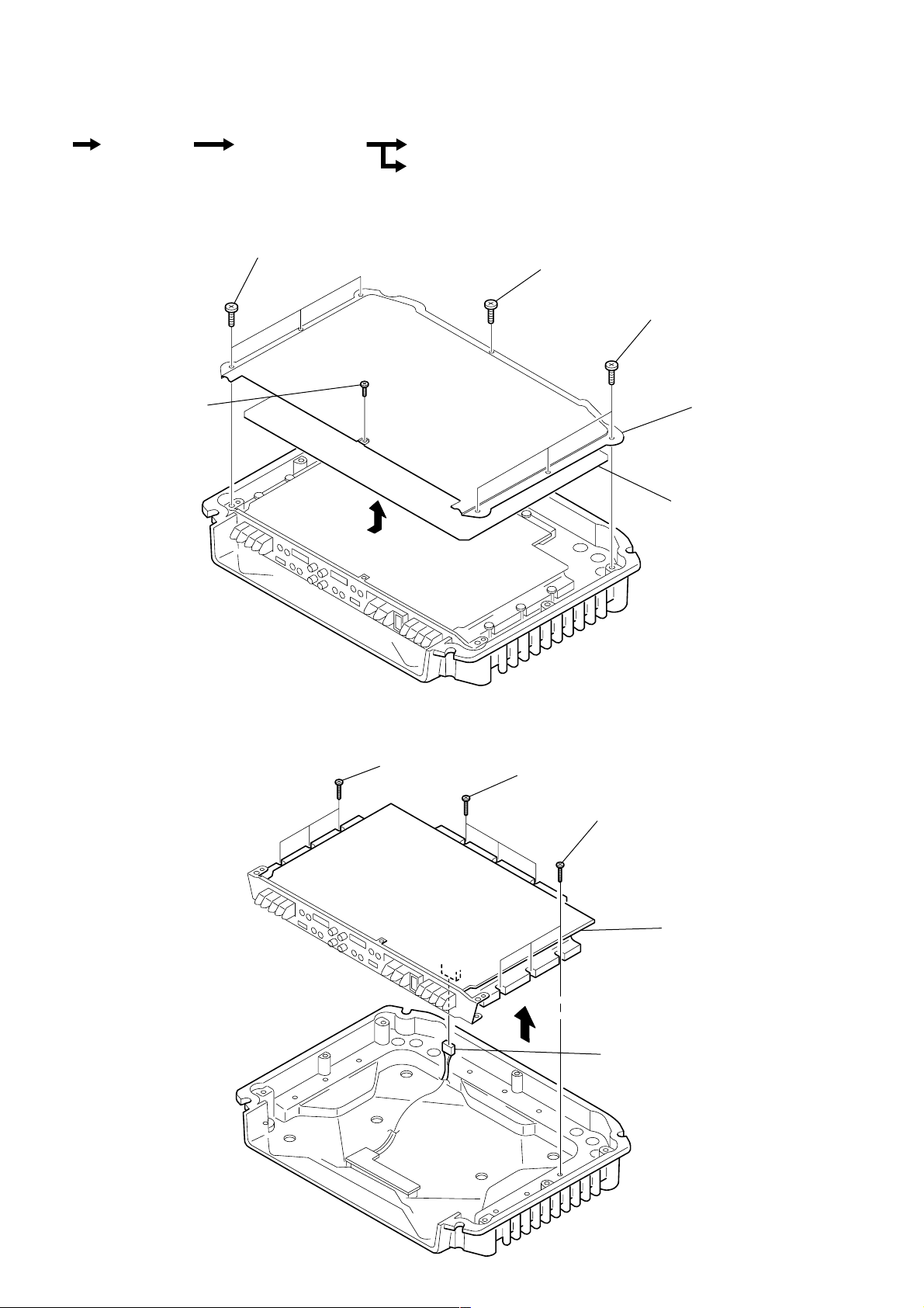
2. DISASSEMBLY
2-1. Plate, Bottom ....................................................................... 6
2-2. AMP Board Section ............................................................. 6
2-3. AMP Board, Filter (A) Board, Filter (B) Board .................. 7
2-4. LED Board ........................................................................... 7
3. ELECTRICAL ADJUSTMENT...................................... 8
4. DIAGRAMS
4-1. Block Diagram ..................................................................... 9
4-2. Printed Wiring Board –AMP Section– .............................. 11
4-3. Schematic Diagram –AMP Section (1/2)– ........................ 12
4-4. Schematic Diagram –AMP Section (2/2)– ........................ 13
4-5. Schematic Diagram –Filter (A), Filter (B),
LED Section– .................................................................... 14
4-6. Printed Wiring Boards –Filter (A), Filter (B),
LED Section– .................................................................... 15
5. EXPLODED VIEWS
5-1. Heat Sink (Main) Section .................................................. 17
5-2. AMP Board Section ........................................................... 18
6. ELECTRICAL PARTS LIST ........................................ 19
SAFETY-RELATED COMPONENT WARNING!!
COMPONENTS IDENTIFIED BY MARK 0 OR DOTTED LINE
WITH MARK 0 ON THE SCHEMATIC DIAGRAMS AND IN
THE PARTS LIST ARE CRITICAL TO SAFE OPERATION.
REPLACE THESE COMPONENTS WITH SONY PARTS WHOSE
PART NUMBERS APPEAR AS SHOWN IN THIS MANUAL OR
IN SUPPLEMENTS PUBLISHED BY SONY.
2
SECTION 1
LEVEL
HPF
OFF
LPF
Phase shift
Normal
AMP
Power
Lch
LEVEL
HPF
OFF
LPF
Inverted
AMP
Power
Rch
BTL.
Lch
Rch
(BTL.)
FILTER
FILTER
LOW BOOST
LOW BOOST
TEST
TONE
Phase shift
10
10
0
40 100 1k
10
0
-10
-20
-30
-40
-50
-60
-70
-80
10 100 1k
HIGH PASS
50Hz
150Hz
300Hz
50Hz
LOW PASS
150Hz
300Hz
FILTER
LPF OFF HPF
LEVEL
LOW BOOST
(40Hz)
MIN MAX0dB +10dB
50Hz 300Hz
0˚
180˚
PHASE
TEST
TONE
POWER/PROTECTOR
OVER CURRENTPOWER OFFSET THERMAL
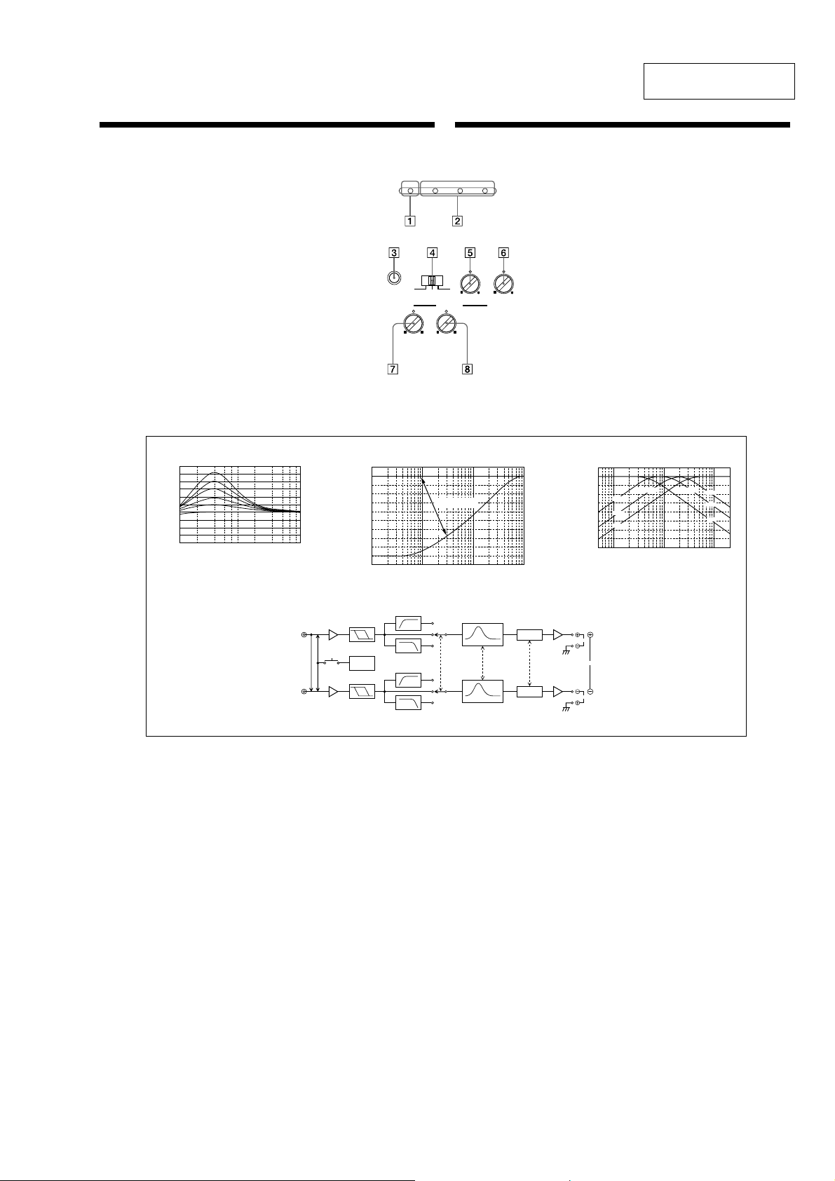
Location and Function of Controls
1 POWER indicator
Lights up in green during operation.
2 PROTECTOR indicator
• OVER CURRENT:
Lights up in red when receiving a powerful signal.
• OFFSET:
Lights up in red when the voltage going out to the Speaker terminal or the Pin
Jack is too high.
• THERMAL:
Lights up in red when the temperature rises to an unsafe level.
3 TEST-TONE button
When the button is pressed, operations of a built-in Oscillator allow the System
conditions to check.
Hearing the tones, the System is in good conditions.
4 FILTER selector switch
When the switch is in the LPF position, the filter is set to low-pass. When in the
HPF position, the filter is set to high-pass.
5 Cut-off frequency adjustment control
Sets the cut-off frequency (50–300 Hz) for the low-pass or high-pass filters.
6 PHASE SHIFT ADJUSTMENT control
Adjusting a phase shift for Subwoofer driving by using the knob, comes true a
controlled rich bass playback preventing by interference from Full range speakers.
7 LOW BOOST level control
Turn this control to boost the frequencies around 40 Hz to a maximum of 10
dB.
8 LEVEL adjustment control
The input level can be adjusted with this control when using source equipment
made by other manufacturers. Turn it to MAX when the output level of the car
audio seems low.
Emplacement et fonction des commandes
1 Indicateur POWER
S’allume en vert en cours fonctionnement.
2 Indicateur PROTECTOR
• OVER CURRENT:
S’allume en vert lors de la réception d’un signal puissant.
• OFFSET:
S’allume en rouge lorsque la tension de sortie vers le terminal du hautparleur ou la prise à broches est trop élevée.
• THERMAL:
S’allume en rouge lorsque la température atteint un niveau trop dangereux.
3 Touche TEST-TONE
Lorsque vous appuyez sur cette touche, la mise en marche d’un oscillateur
intégré permet de vérifier le système.
Si vous entendez le signal, le système est en bonne condition.
4 Sélecteur FILTER
Lorsque le commutateur est en position LPF, le filtre est mis sur passe-bas.
Lorsqu’il est en position HPF, le filtre est mis sur passe-haut.
5 Commandes de réglage de la fréquence de coupure
Règle la fréquence de coupure (50–300 Hz) des filtres passe-bas ou passe-haut.
6 Commande PHASE SHIFT ADJUSTMENT
Réglez le déphasage du Subwoofer à l’aide du bouton afin d’obtenir une
restitution fidèle des fréquences graves en évitant les interférences avec les
fréquences émises par les haut-parleurs principaux.
7 Commande de niveau LOW BOOST
Tournez cette commande pour amplifier les fréquences autour de 40 Hz à un
maximum de 10 dB.
8 Commande de réglage LEVEL
Le niveau d’entrée peut se régler avec cette commande lors de l’utilisation
d’équipements source d’autres fabricants. Mettez-le sur MAX lorsque le niveau
de sortie de l’installation audio paraît faible.
Circuit Diagram / Schéme du circuit
LOW BOOST
dB
FREQUENCY Hz
FREQUENCY Hz
dB
Cut-off frequency/Fréquence de coupure
20
0
-20
-40
-60
-80
-100
-120
-140
-160
10 100 1k 10k
-180
-200
0ß
180ß
Position of knobs
Position des boutons
FREQUENCY Hz
deg
PHASE SHIFT
Front :
Avant :
Rear : same as Front
Arrière : identique à l’avant
GENERAL
XM-1004GX
This section is extracted
from instruction manual.
3
XM-1004GX
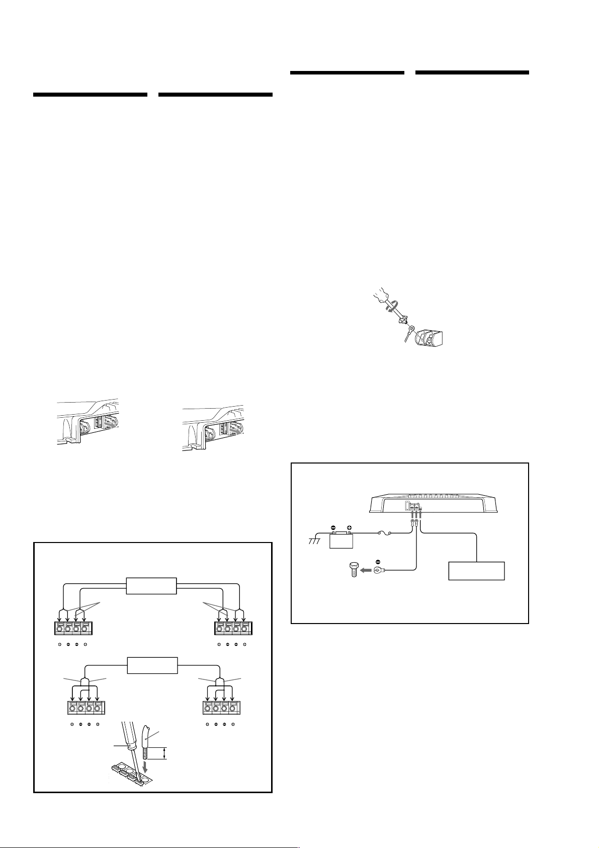
Connections Connexions
Precautions
• This unit is designed for negative ground 12 V DC
operation only.
•
Use speakers with suitable impedance.
— 2 to 8 Ω (stereo).
• Do not connect any active speakers (with built-in
amplifiers) to the speaker terminals of the unit.
Doing so may damage the active speakers.
• Avoid installing the unit where:
—
it would be subject to high temperatures such as
from direct sunlight or hot air from the heater
—
it would be exposed to rain or moisture
—
it would be subject to dust or dirt.
• If your car is parked in direct sunlight and there is a
considerable rise in temperature inside the car,
allow the unit to cool down before use.
• When installing the unit horizontally, be sure not to
cover the fins with the floor carpet etc.
• If this unit is placed too close to the car radio,
interference may occur. In this case, relocate the
amplifier away from the car radio.
• If no power is being supplied to the master unit,
check the connections.
• This power amplifier employs a protection circuit*
to protect the transistors and speakers if the
amplifier malfunctions. Do not attempt to test the
protection circuits by covering the heat sink or
connecting improper loads.
• Do not use the unit on a weak battery as its
optimum performance depends on a good power
supply.
• For safety reasons, keep your car audio volume
moderate so that you can still hear sounds outside
your car.
• As PHASE SHIFT functions to reduce the
interference of the Full Range Speaker and Sub
Woofer, systems with Full Range Speakers using
HPF may not produce sufficient effect.
Fuse Replacement
If the fuse blows, check the power connection and
replace the fuse. If the fuse blows again after
replacement, there may be an internal malfunction. In
such a case, consult your nearest Sony dealer.
Warning
When replacing the fuse, be sure to use one matching
the amperage stated above the fuse holder. Never use
a fuse with an amperage rating exceeding the one
supplied with the unit as this could damage the unit.
Précautions
• Cet appareil est conçu pour fonctionner uniquement
sur courant continu de 12 volts avec masse négative.
• Utilisez des haut-parleurs d’une impédance
appropriée.
—
2 à 8 Ω (stéréo).
• Ne raccordez pas de haut-parleurs actifs (avec
amplificateur intégré) aux bornes de haut-parleurs
de cet appareil; ils pourraient être endommagés.
• Evitez d’installer l’appareil à des endroits où:
—
il serait exposé à des températures élevées,
comme sous les rayons directs du soleil ou à
proximité d’une bouche d’air chaud
—
il serait exposé à la pluie ou à l’humidité
—
il serait exposé à la poussière ou à la saleté.
• Si votre voiture était garée en plein soleil et que la
température a considérablement augmenté à
l’intérieur, laissez refroidir l’appareil avant de
l’utiliser.
• Lorsque vous installez l’appareil à l’horizontale,
veillez à ne pas recouvrir la grille d’aération avec le
tapis, etc.
• Si cet appareil est trop près de l’autoradio, il est
possible qu’il y ait des interférences. Dans ce cas,
éloignez l’amplificateur de l’autoradio.
• Si l’appareil principal n’est pas alimenté, vérifiez les
connexions.
• Cet amplificateur est équipé d’un circuit* destiné à
protéger les transistors et les haut-parleurs en cas de
défaillance. N’essayez pas de tester l’efficacité de ce
circuit en recouvrant les dissipateurs thermiques ou
en effectuant des connexions inadéquates.
• N’utilisez pas l’appareil sur une batterie faible, car
sa performance maximale dépend d’une bonne
alimentation en électricité.
• Pour des raisons de sécurité, écoutez l’autoradio à
un volume modéré afin d’entendre les bruits
extérieurs.
• Les fonctions PHASE SHIFT permettant de réduire
les interférences de l’enceinte de plage totale et
d’extrêmes graves, les systèmes avec des enceintes à
plage totale utilisant HPF ne produisent pas un effet
suffisant.
Remplacement du fusible
Si le fusible saute, vérifiez les connexions du fil
d’alimentation et remplacez le fusible. S’il saute de
nouveau, un mauvais circuit interne peut en être la
cause. Dans ce cas, consultez votre concessionnaire
Sony.
Avertissement
En cas de remplacement du fusible, veillez à utiliser
un fusible dont l’intensité correspond à celle inscrite
sur le porte-fusible. N’utilisez jamais de fusible dont
l’intensité dépasse celle du fusible fourni avec
l’appareil, car vous risqueriez d’endommager
l’appareil.
Caution
•
Before making any connections, disconnect the
ground terminal of the car battery to avoid short
circuits.
•
Be sure to use speakers with an adequate power
rating. If you use small capacity speakers, they
may be damaged.
•
Do not connect the # terminal of the speaker
system to the car chassis, and do not connect the
# terminal of the right speaker with that of the
left speaker.
•
Install the input and output cords away from the
power supply lead as running them close
together can generate some interference noise.
•
This unit is a high powered amplifier. Therefore,
it may not perform to its full potential if used
with the speaker cords supplied with the car.
•
If your car is equipped with a computer system
for navigation or some other purpose, do not
remove the ground wire from the car battery. If
you disconnect the wire, the computer memory
may be erased. To avoid short circuits when
making connections, disconnect the +12 V power
supply lead until all the other leads have been
connected.
Make the terminal
connections as illustrated below.
Note
Tighten the screws firmly, but be careful not to apply too much
force* as doing so may damage the screws.
* The torque value should be less than 1 N•m.
Attention
•
Avant d’effectuer les connexions, débranchez le
fil de masse de la borne de la batterie pour éviter
un court-circuit.
•
Utilisez des haut-parleurs d’une capacité
adéquate. Si vous utilisez des haut-parleurs de
faible capacité, ils risquent d’être endommagés.
•
Ne raccordez pas la borne # des haut-parleurs à
la carrosserie de la voiture ni la borne # du
haut-parleur droit à celle du haut-parleur
gauche.
•
Eloignez les cordons d’entrée et de sortie du fil
d’alimentation électrique pour éviter que des
interférences ne se produisent.
•
Cet appareil est un amplificateur de haute
puissance et il peut ne pas atteindre sa puissance
maximale si les cordons de haut-parleurs
originaux de la voiture lui sont raccordés.
•
Si votre voiture est équipée d’un ordinateur de
bord pour la navigation ou à toute autre fin, ne
débranchez pas le fil de masse de la batterie de la
voiture. Si vous débranchez ce fil, toute la
mémoire de l’ordinateur sera effacée. Pour éviter
un court-circuit lorsque vous effectuez
branchements, branchez le fil d’alimentation de
+12 volts uniquement après avoir branché tous
les autres fils.
Effectuez les connexions de la
manière indiquée ci-dessous.
Remarque
Ne serrez* pas trop fort la vis car vous pourriez l’endommager.
* Le couple de serrage devrait être inférieur à 1 N•m.
*
Protection circuit
This amplifier is provided with a protection circuit that
operates in the following cases:
— when the unit is overheated
— when a DC current is generated
— when the speaker terminals are short circuited.
The PROTECTOR indicator lights up in red and the unit will
shut down.
If this happens, turn off the connected equipment, take out the
cassette tape or disc, and determine the cause of the
malfunction. If the amplifier has overheated, wait until the
unit cools down before use.
If you have any questions or problems concerning
your unit that are not covered in this manual, please
consult your nearest Sony dealer.
*
Circuit
Cet amplificateur est équipé d’un circuit de protection qui
entre en service dans les cas suivants:
— surchauffe de l’appareil
— production d’un courant continu
— court-circuit aux bornes des haut-parleurs.
L’indicateur PROTECTOR s’allume en rouge et l’appareil
s’arrête.
Si le cas se présente, coupez l’alimentation de l’appareil
raccordé et éjecrez la cassette ou le disque compact avant
d’examiner la cause de la défaillance. Si l’amplificateur est
trop chaud, attendez qu’il refroidisse.
Pour toute question ou problème qui ne serait pas
traité dans ce manuel, consultez votre concessionaire
Sony.
Speaker cord direct in connector
Cordon de haut-parleur directement dans le connecteur
*1
White
Blanc
*2
White
Blanc
Left speaker
Haut-parleur gauche
Right speaker
Haut-parleur droit
Gray
Gris
FLFLFRF
R
Left speaker
Haut-parleur gauche
FLFLFRF
R
Flat-head screwdriver
Tournevis à lame plate
Black-striped cord
Cordon rayé noir
Black/White
Noir/Blanc
Front
Avant
Rear
Arrière
Car audio
Autoradio
Car audio
Autoradio
Cord diameter 0.3 – 1.25 mm (AWG 22 – 16)
Section du cordon : 0,3 – 1,25 mm (AWG 22 – 16)
Right speaker
Haut-parleur droit
Left speakera
Haut-parleur gauche
Black-striped cord
Cordon rayé noir
Right speaker
Haut-parleur droit
Gray
Gris
7
/16)
11 (
Green
Vert
RLRLRRR
RLRLRRR
R
Purple
Mauve
R
Black/Gray
Noir/Gris
Unit : mm (in.)
Unitè : mm (po.)
Power Connection Leads
Câbles d’alimentation
+12 V car battery
Batterie de voiture +12 V
Remote output*
Car audio
Autoradio
Sortie de
télécommande*
(REM OUT)
2
aux bornes
Fuse (40 A)
Fusible (40 A)
to a metal point
of the car
vers une partie
métallique de la
carrosserie
* If you have the factory original or some other car audio without a remote out-put on the amplifier, connect the remote input
terminal (REMOTE) to the accessory power supply.
* Si vous disposez du modèle d’origine ou d’un autre autoradio dont l’amplificateur ne comporte pas de sortie de télécommande,
raccordez la borne d’entrée de télécommande (REMOTE) à la prise d’alimentation accessoires.
Notes on the power supply
•
Connect the +12 V power supply lead only after all the other
leads have been connected.
•
Be sure to connect the ground lead of the unit
securely to a metal point of the car. A loose
connection may cause a malfunction of the
amplifier.
•
Be sure to connect the remote control lead of the car audio to
the remote terminal.
•
When using a car audio without a remote output on the
amplifier, connect the remote input terminal (REMOTE) to
the accessory power supply.
•
Use the power supply lead with a fuse attached (40 A).
•
Place the fuse in the power supply lead as close as possible to
the car battery.
•
Make sure that the leads to be connected to the +
GND
terminals of this unit are larger than 10-Gauge (AWG-
10) or have a sectional area of more than 5 mm
12 V
2
.
Remarques sur l’alimentation électrique
•
Raccordez le câble d’alimentation +12 V uniquement après
avoir réalisé toutes les autres connexions.
•
Raccordez correctement le fil de masse à une partie
métallique de la voiture. Une connexion lâche peut
provoquer un dysfonctionnement de l’amplificateur.
•
Veillez à raccorder le fil de télécommande de l’autoradio à la
borne de télécommande.
•
Si vous utilisez un autoradio dont l’amplificateur ne
comporte pas de sortie de télécommande, raccordez la borne
d’entrée de la télécommande (REMOTE) à la prise
d’alimentation accessoires.
•
Utilisez un câble d’alimentation muni d’un fusible (40 A).
•
Fixez le câble d’alimentation le plus près possible de la
batterie de voiture.
•
Vous devez raccorder des câbles de calibre supérieurs à 10
and
(AWG-10) ou d’une section supérieure à 5 mm
+12V
et
GND
.
4
XM-1004GX
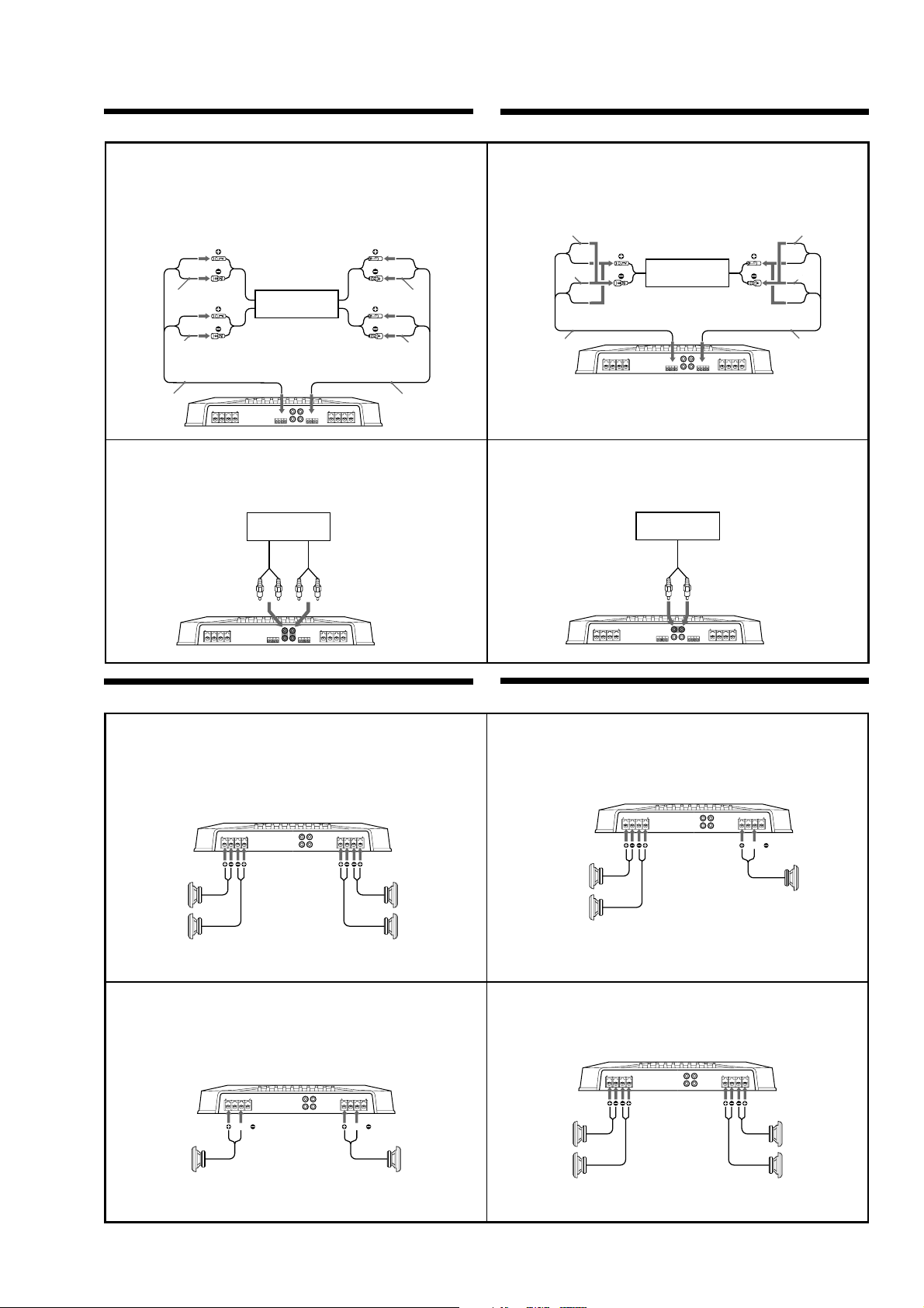
Input Connections
High Level Input Connection (with Speaker
Connection 1, 2 or 4)
Connexion à l’entrée de haut niveau (avec
connexion de haut-parleur 1, 2 ou 4)
Car audio
Autoradio
Car audio
Autoradio
LINE OUT
Rear right
speaker output
Sortie de hautparleur arrière
droit
Rear left speaker
output
Sortie de hautparleur arrière
gauche
*1
Rear
Arrière
Front right speaker
output
Front Right e
Avant Droit e
Front Left e
Avant
Gauche e
Input cord
(Not supplied)
Câble d’entrée
(Non fournis)
Front Right E
Avant Droit E
Front Left E
Avant Gauche E
Sortie de hautparleur avant droit
Front left speaker
output
Sortie de hautparleur avant
gauche
*1
Line Input Connection (with Speaker Connection
1, 2 or 4)
Connexion d’entrée de ligne (avec connexion de
haut-parleur 1, 2 ou 4)
Front
Avant
Rear Right E
Arrière Droit E
Rear Left E
Arrière Gauche E
Input cord
(Not supplied)
Câble d’entrée
(Non fournis)
AA
A
AA
Rear Right e
Arrière Droit e
Rear Left e
Arrière
Gauche e
CC
C
CC
Connexions d’entrée
High Level Input Connection (with Speaker
Connection 3)
Connexion à l’entrée de haut niveau (avec
connexion de haut-parleur 3)
Striped
Rayé
Striped
Rayé
Input cord
(Not supplied)
Câble d’entrée
(Non fournis)
Note
Make sure that the right speaker output from the car audio
is connected to the connector marked “REAR” on the unit.
Line Input Connection (with Speaker Connection 3)
Connexion d’entrée de ligne (avec connexion de
haut-parleur 3)
Note
Make sure that the line output
from the car audio is connected to
the jack marked “L (BTL)” on the
unit.
Left speaker output
Sortie de hautparleur gauche
*2 *2
Left channel
Canal gauche
Right speaker output
Sortie de hautparleur droit
Car audio
Autoradio
Remarque
Assurez-vous que la sortie du haut-parleur droit de
l’autoradio est raccordée au connecteur portant l’indication
“REAR” sur l’appareil.
Car audio
Autoradio
LINE OUT
Remarque
Vérifiez que la sortie de ligne de
Right channel
Canal droit
l’autoradio est raccordée à la prise
portant l’indication “L (BTL)” sur
l’appareil.
BB
B
BB
Striped
Rayé
Striped
Rayé
Input cord
(Not supplied)
Câble d’entrée
(Non fournis)
DD
D
DD
Speaker Connections
4-Speaker System (with Input Connection A or C)
Système à 4 haut-parleurs (avec connexion d’entrée
A ou C)
For details on the settings of switches and controls, refer
to “Location and Function of Controls.”
Left
Gauche
Front speakers
(min. 2Ω)
Haut-parleurs avant
(min. 2Ω)
Right
Droit
2-Speaker System (with Input Connection B or D)
Système à 2 haut-parleurs (avec connexion d’entrée
B ou D)
For details on the settings of switches and controls, refer
to “Location and Function of Controls.”
BTL BTL BTL BTL
Left speaker
(min. 4Ω)
Haut-parleur gauche
(min. 4Ω)
Pour plus de détails sur les réglages des commutateurs et
commandes, reportez-vous à “Emplacement et fonction des
commandes.”
Left
Gauche
Pour plus de détails sur les réglages des commutateurs et
commandes, reportez-vous à “Emplacement et fonction des
commandes.”
Right
Droit
11
1
11
Rear speakers
(min. 2Ω)
Haut-parleurs arrière
(min. 2Ω)
33
3
33
Right speaker
(min. 4Ω)
Haut-parleur droit
(min. 4Ω)
Raccordement de haut-parleurs
3-Speaker System (with Input Connection A or C)
Système à 3 haut-parleurs (avec connexion
d’entrée A ou C)
For details on the settings of switchesand controls, refer
to “Location and Function of Controls.”
Left
Full range speakers
(min. 2Ω)
Haut-parleurs pleine
gamme (min. 2 Ω)
Notes
•
In this system, the volume of the subwoofer will be
controlled by the car audio fader control.
•
In this system, the output signals to the subwoofer are a
combination of both the REAR L and R INPUT jacks or
the REAR high level input connector signals.
Gauche
Right
Droit
2-Way System (with Input Connection A or C)
Système à 2 voies (avec connexion d’entrée
A ou C)
For details on the settings of switches and controls, refer
to “Location and Function of Controls.”
Left
Full range speakers
(min. 2Ω)
Haut-parleurs pleine
gamme (min. 2 Ω)
Note
In this system, the volume of the subwoofers will be
controlled by the car audio fader control.
Gauche
Right
Droit
Pour plus de détails sur les réglages des commutateurs et
commandes, reportez-vous à “Emplacement et fonction des
commandes.”
BTL BTL
Remarques
•
Dans ce système, le volume du subwoofer est contrôlé par
le fader de l’autoradio.
•
Sur cet appareil, les signaux transmis vers le subwoofer
sont constitués des signaux des prises REAR L et R
INPUT.
Pour plus de détails sur les réglages des commutateurs et
commandes, reportez-vous à “Emplacement et fonction des
commandes.”
Right
Droit
Left
Gauche
Remarque
Dans ce système, le volume des subwoofers est contrôlé par le
fader de l’autoradio.
Subwoofer
(min. 4Ω)
Subwoofer
(min. 4Ω)
Subwoofers
(min. 2Ω)
Subwoofers
(min. 2Ω)
22
2
22
44
4
44
5
XM-1004GX
SECTION 2
DISASSEMBLY
• The equipment can be removed using the following procedure.
Set Plate, Bottom
AMP Board Section
AMP Board, Filter (A) Board, Filter (B) Board
LED Board
Note : Follow the disassembly procedure in the numerical order given.
2-1. PLATE, BOTTOM
3
BTP 3x6
4
P 2.6x2.8
6
BTP 3x6
2
1
BTP 3x6
5
7
sheet, insulating
plate, bottom
2-2. AMP BOARD SECTION
1
B.TT. 3x14
2
B.TT. 3x14
4
3
B.TT. 3x14
5
CNP808
6
AMP board
6
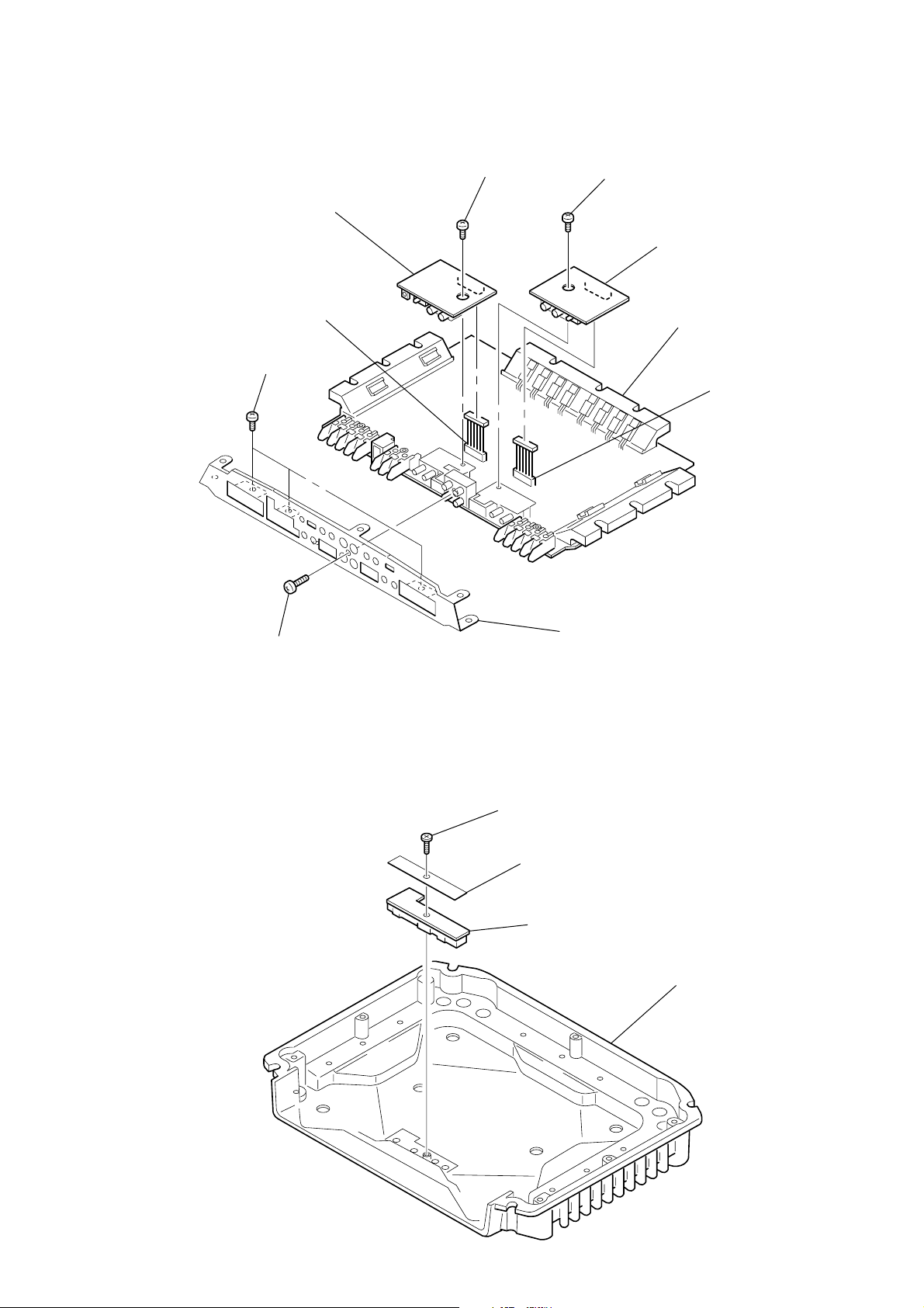
2-3. AMP BOARD, FILTER (A) BOARD, FILTER (B) BOARD
)
4
BVTT 3x5
6
FILTER (A) board
5
CNP806
2
P 3x8
7
BVTT 3x5
9
FILTER (B) board
0
AMP board
8
CNP807
XM-1004GX
2-4. LED BOARD
1
P 3x8
3
panel (4ch), front
1
BTP 3x6
2
sheet (LED), insulating
3
LED board
heat sink (main
7
XM-1004GX
SECTION 3
ELECTRICAL ADJUSTMENT
Bias Adjustment
Note : The Bias adjustment should be performed only if any of
Q108 and Q110 for VR101, Q208 and Q210 for VR201,
Q308 and Q310 for VR301, and Q408 and Q410 for VR401
are replaced.
Setting :
Stabilized
Power supply
B+,REM terminals
set
GND terminal test points
Procedure:
1. Rotate variable resistors VR101 (FRONT L-CH), VR201
(FRONT R-CH), VR301 (REAR L-CH) and VR401 (REAR RCH) full counterclockwise as seen from the pattern side to
minimize the bias current.
2. The input signal is with no signal.
3. Connect the stabilized power supply between B+ and REM
terminals and gradually increase the voltage to 14.4 V while
checking for any abnormal current.
4. Adjust VR101 (FRONT L-CH), VR201 (FRONT R-CH), VR301
(REAR L-CH) and VR401 (REAR R-CH) so that the digital
voltmeter connected between the respective test points reads
4.5±1 mV.
Digital
Voltmeter
+
_
Adjustment Location :
– AMP BOARD (COMPONENT SIDE) –
VR201
BIAS ADJUSTMENT
(FRONT R-CH)
VR101
BIAS ADJUSTMENT
(FRONT L-CH)
Test Point Location :
– AMP BOARD (CONDUCTOR SIDE) –
TP302
TP301
TP402
TP401
VR301
BIAS ADJUSTMENT
(REAR L-CH)
VR401
BIAS ADJUSTMENT
(REAR R-CH)
TP201
TP202
TP101
TP102
RV Ref. No. Test points
VR101 TP101 and TP102
VR201 TP201 and TP202
VR301 TP301 and TP302
VR401 TP401 and TP402
8
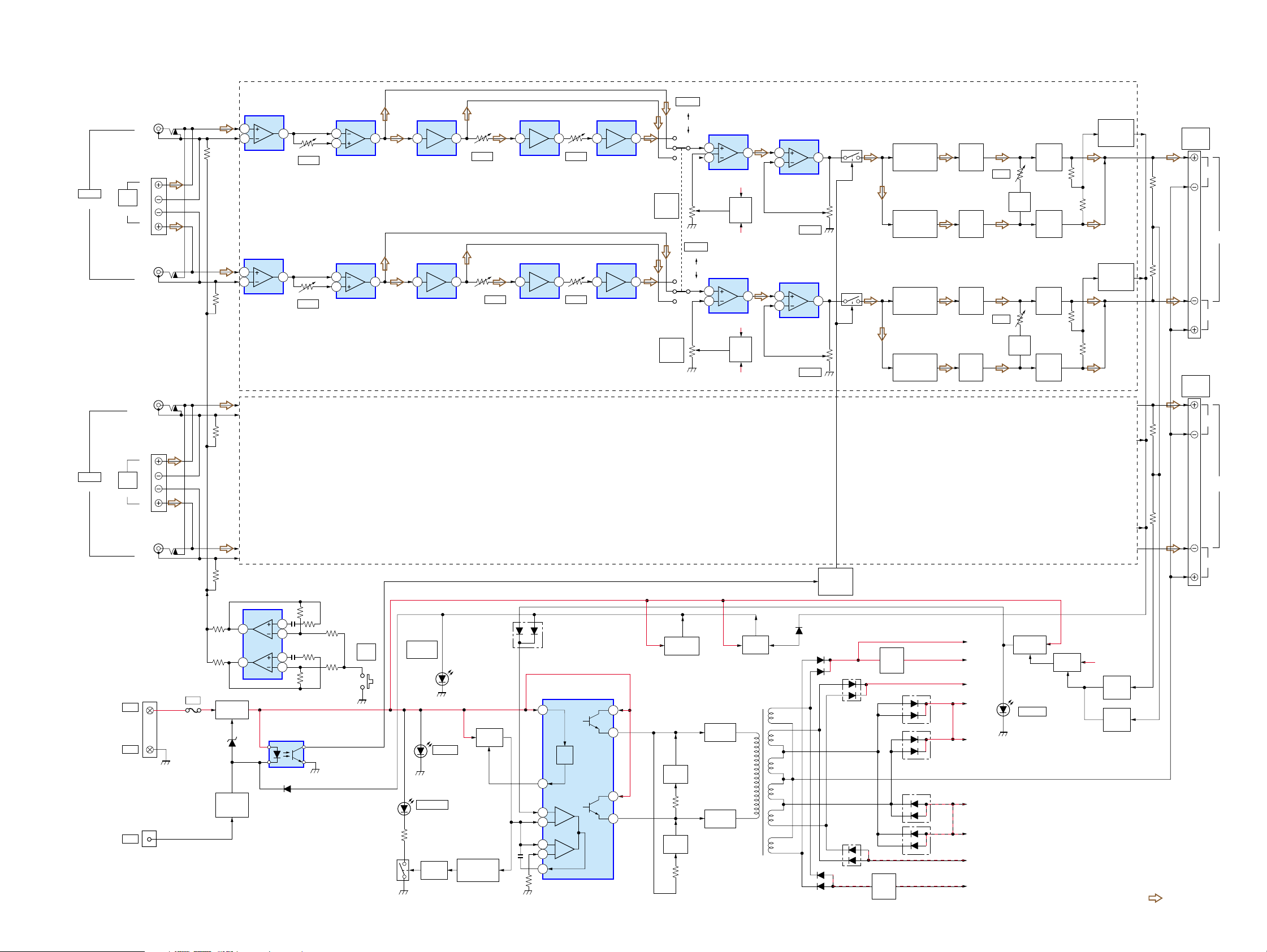
4-1. BLOCK DIAGRAM
CNJ805-1
L
(BTL)
CN809
L
INPUT
(FRONT)
HIGH
LEVEL
(INPUT (FRONT))
R
CNJ805-2
R
CNJ805-3
L
(BTL)
PRE AMP
IC801 (2/2)
5
6
PRE AMP
IC801 (1/2)
3
2
XM-1004GX
SECTION 4
DIAGRAMS
S801-1
VR803-1
LOW
BOOST
(40Hz)
VR803-2
LOW
BOOST
(40Hz)
FILTER
LPF
OFF
HPF
S801-2
FILTER
LPF
OFF
HPF
PHASE AMP
IC802 (2/2)
7
VR801-1
PHASE
1
VR801-2
PHASE
6
5
PHASE AMP
IC802 (1/2)
2
3
7 5 7 6 7 6 7
1 3 1 2 1 2 1
H.P.F
IC803 (2/2)
H.P.F
IC803 (1/2)
VR802-2
FILTER
VR802-3
FILTER
L.P.F
IC804 (2/2)
L.P.F
IC804 (1/2)
VR802-1
FILTER
VR802-4
FILTER
L.P.F
IC805 (2/2)
L.P.F
IC805 (1/2)
LOW BOOST
IC813 (2/2)
5
6
LOW BOOST
IC814 (2/2)
3
2
(FRONT)
7
B+
(+14.2V)
LEVEL
SHIFT
Q101
B–
(–14.2V)
1
B+
(+14.2V)
LEVEL
SHIFT
Q201
B–
(–14.2V)
(REAR)
LINE AMP
IC813 (1/2)
3
2
LINE AMP
IC814 (1/2)
5
6
VR804-1
LEVEL
VR804-2
LEVEL
LINE
SWITCH
Q102
1
LINE
SWITCH
Q202
7
DIFFERENTIAL
AMP
Q103
DIFFERENTIAL
AMP
Q104
DIFFERENTIAL
AMP
Q203
DIFFERENTIAL
AMP
Q204
DRIVER
AMP
Q105
DRIVER
AMP
Q107
DRIVER
AMP
Q205
DRIVER
AMP
Q207
VR101
BIAS
VR201
BIAS
BIAS
Q106
BIAS
Q206
POWER
AMP
Q108
POWER
AMP
Q110
POWER
AMP
Q208
POWER
AMP
Q210
OVERLOAD
DET
Q112
OVERLOAD
DET
Q212
CN803
FRONT
SPEAKER
OUT
CN804
REAR
SPEAKER
OUT
L
BTL
R
L
INPUT
(REAR)
CN810
HIGH
LEVEL
(INPUT (REAR))
CNJ805-4
R
CN801
+12V
GND
CNJ802
REM
L
BTL
R
R
D816
D910
D911
D912
MUTE
SWITCH
Q805
D909,910
D909
RECT
D903
D903
RECT
D906
RECT
D906
D911,912
RECT
B–
REG
Q911
B+
REG
Q910
D904
D907
D904,905,907,908
RECT
D908
D905
B+
(+23.5V)
B+
(+14.2V)
B+
(+42V)
B+
(+36V)
B+
(+36V)
B–
(–35V)
B–
(–35V)
B–
(–42V)
B–
(–14.2V)
LED DRIVE
Q804
LD803
OFFSET
(PROTECTOR)
SWITCH
Q806
B– (–35V)
OFFSET
DET
Q807
OFFSET
DET
Q809
• Signal path
: AUDIO
F901
40A
D902
REG
Q901,902
POWER
ON/OFF
Q903
TEST TONE
GENERATOR
IC812
1
7
3
2
5
6
DC DET
IC811
D815
S802
TEST
TONE
SWITCH
Q808
LD802
OVER
CURRENT
(PROTECTOR)
(PROTECTOR)
LD801
THERMAL
(PROTECTOR)
B+ CONT
Q802
LD804
POWER
B+ CONT
Q801
TEMP DET
D801,804,805,
808,809
D812
DC-DC CONVERTER
IC901
12
REF.
REG
14
1
2
15
16
3
LED DRIVE
Q803
11
10
DRIVER
Q904
8
9
DRIVER
Q905
INVERTER
Q906,907
INVERTER
Q908,909
SWITCH
Q810
DC-DC
CONVERTER
TRANSFORMER
T901
• Front-ch : same as Rear-ch.
99
 Loading...