

Sony XL505 Service Manual
XL-505/505C,CP-505B
SERVICE MANUAL
No. S1808XL505///
XL-505
XL-505C
CP-505B
XL-505 and CP-505B constitute XL-505.
XL-505C and CP-505B constitute XL-505C.
• In the interests of user-safety the set should be restored to its
original condition and only parts identical to those specified be
used.
CONTENTS
Page
IMPORTANT SERVICE NOTES (XL-505 ONLY) .............................................................................................................. 2
SPECIFICATIONS ............................................................................................................................................................. 2
NAMES OF PARTS ........................................................................................................................................................... 3
OPERATION MANUAL ...................................................................................................................................................... 5
QUICK GUIDE ................................................................................................................................................................... 6
DISASSEMBLY.................................................................................................................................................................. 7
REMOVING AND REINSTALLING THE MAIN PARTS..................................................................................................... 8
ADJUSTMENT ................................................................................................................................................................... 9
BLOCK DIAGRAM ........................................................................................................................................................... 16
SCHEMATIC DIAGRAM / WIRING SIDE OF P.W.BOARD............................................................................................. 20
VOLTAGE ........................................................................................................................................................................ 26
NOTES ON SCHEMATIC DIAGRAM .............................................................................................................................. 27
TYPE OF TRANSISTOR AND LED ................................................................................................................................. 27
WAVEFORMS OF CD CIRCUIT...................................................................................................................................... 28
TROUBLESHOOTING (CD SECTION) ........................................................................................................................... 29
FUNCTION TABLE OF IC................................................................................................................................................ 34
LCD SEGMENT ............................................................................................................................................................... 41
REPLACEMENT PARTS LIST/EXPLODED VIEW
PACKING OF THE SET (XL-505 ONLY)
SHARP CORPORATION
– 1 –
This document has been published to be used
for after sales service only.
The contents are subject to change without notice.
XL-505/505C,CP-505B
FOR A COMPLETE DESCRIPTION OF THE OPERATION OF THIS UNIT, PLEASE REFER
TO THE OPERATION MANUAL.
IMPORTANT SERVICE NOTES (XL-505 ONLY)
BEFORE RETURNING THE AUDIO PRODUCT
(Fire & Shock Hazard)
Before returning the audio product to the user, perform the
following safety checks.
1. Inspect all lead dress to make certain that leads are not
pinched or that hardware is not lodged between the chassis
and other metal parts in the audio product.
2. Inspect all protective devices such as insulating materials,
cabinet, terminal board, adjustment and compartment
covers or shields, mechanical insulators etc.
3. To be sure that no shock hazard exists, check for leakage
current in the following manner.
* Plug the AC line cord directly into a 120 volt AC outlet.
* Using two clip leads, connect a 1.5k ohm, 10 watt resistor
paralleled by a 0.15µF capacitor in series with all exposed
metal cabinet parts and a known earth ground, such as
conduit or electrical ground connected to earth ground.
* Use a VTVM or VOM with 1000 ohm per volt, or higher,
sensitivity to measure the AC voltage drop across the
resistor (See diagram).
* Connect the resistor connection to all exposed metal parts
having a return path to the chassis (antenna, metal cabinet,
screw heads, knobs and control shafts, escutcheon, etc.)
and measure the AC voltage drop across the resistor.
VTVM
AC SCALE
1.5k ohms
10W
0.15 µ F
TO EXPOSED
METAL PARTS
All check must be repeated with the AC line cord plug connection
reversed.
Any reading of 0.3 volt RMS (this corresponds to 0.2 milliamp.
AC.) or more is excessive and indicates a potential shock
hazard which must be corrected before returning the audio
product to the owner.
TEST PROBE
CONNECT TO
KNOWN EARTH
GROUND
SPECIFICATIONS
XL-505/505C
General
Power source: AC 120 V, 60 Hz
Power consumption: 30 W
Dimensions: Width; 160 mm (6-5/16")
Height; 240 mm (9-1/2")
Depth; 250 mm (9-7/8")
Weight: 2.6 kg (5.7 lbs.)
Amplifier section
Output power: RMS; 10 W (5 W + 5 W)
(10 % T.H.D.)
Output terminals: Speakers; 4 ohms
Headphones; 16-50 ohms
(recommended; 32 ohms)
Tuner section
Frequency range: FM; 87.5 - 108 MHz
AM; 530 - 1,720 kHz
Compact disc player section
Type: Compact disc player
Signal readout: Non-contact, 3-beam semi-
conductor laser pickup
D/A Converter: 1-bit D/A converter
Filter: 8-times oversampling digital filter
Frequency response: 20 - 20,000 Hz
Wow and flutter: Unmeasurable
(less than 0.001% W.peak)
Cassette deck section
Frequency response: 50 - 14,000 Hz (Normal tape)
Signal/noise ratio: 50 dB
Wow and flutter: 0.25 % (WRMS)
CP-505B
Type: Full range speaker system
Speakers: 10 cm (4") full-range speaker
Rated input power: 5 W
Maximum input power:10 W
Impedance: 4 ohms
Dimensions: Width; 145 mm (5-3/4")
Height; 240 mm (9-1/2")
Depth; 183 mm (7-1/4")
Weight: 1.1 kg (2.4 lbs.)/each
Specifications for this model are subject to change without
prior notice.
– 2 –
XL-505/505C
Front Panel
1. Function/Band/Track Number Indicator
2. Volume Indicator
3. Timer Indicator
4. Record Indicator
5. Sleep Indicator
6. Repeat Indicator
7. Play Indicator
8. Extra Bass/Equalizer Indicator
9. Random Indicator
10. Memory Indicator
11. FM Stereo Mode Indicator
12. FM Stereo Indicator
13. CD Compartment
14. On/Stand-by Button
15. Remote Control Sensor
16. Record Pause/Beat Cancel Button
17. Memory/Set Button
18. (CD) Track Down/Review Button
(TAPE) Rewind Button
(TUNER) Preset Down Button
19. Headphone Socket
20. CD Eject Button
21. Function Selector Button
22. Band Selector Button
23. Extra Bass/Equalizer Mode Button
24. Volume Up/Down Buttons
25. (CD) Play/Pause Button
(TAPE) Play Button
(TUNER) Tuning Up Button
26. (CD/TAPE) Stop Button
(TUNER) Clear Button
27. (CD) Track Up/Cue Button
(TAPE) Fast Forward Button
(TUNER) Preset Up Button
28. Cassette Compartment
NAMES OF PARTS
6
13
14
15
16
17
18
19
1
VOL
EQ
78
XL-505/505C,CP-505B
2
AM PM REC SLEEP
RANDOM MEMORY ST
91011
3
4
5
kHz
MHz
12
20
21
22
23
24
25
26
27
28
Rear Panel
1. AC Power Input Socket
2. FM/AM Loop Aerial Socket
3. Speaker Terminals
2
3
1
– 3 –
XL-505/505C,CP-505B
CP-505B
Speaker Section
1. Full-Range Speaker
2. Bass Reflex Duct
3. Speaker Wire
XL-505/505C
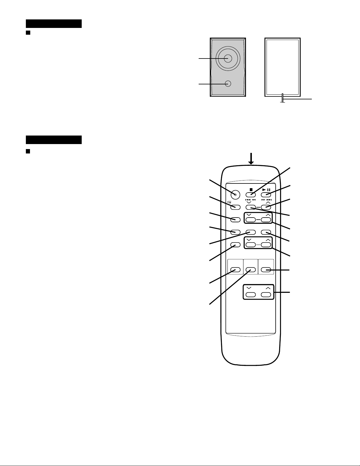
Remote Control
1
2
3
1
1. Remote Control Transmitter LED
2. On/Stand-by Button
3. (CD) Repeat/Random Button
4. (CD/TUNER) Memory/Set Button
5. (CD/TUNER) Clear Button
6. Timer/Set Button
7. Sleep Button
8. (CD/TAPE) Stop Button
9. (CD) Play/Pause Button
(TAPE) Play Button
10. (CD) Track Up/Cue Button
(TAPE) Fast Forward Button
(TUNER) Preset Up Button
11. (CD) Track Down/Review Button
(TAPE) Rewind Button
(TUNER) Preset Down Button
12. Tuning Up/Down Buttons
13. Timer Button
14. Timer Up/Down Buttons
15. Function Selector Button
16. Band Selector Button
17. Extra Bass/Equalizer Mode Button
18. Volume Up/Down Buttons
2
3
4
5
6
7
15
16
ON/
STAND-BY
/RANDOM
MEMORY/
SET
CLEAR
SLEEP
FUNCTION
TIMER/
SET
BAND
PRESET
TUNING
TIMER
X-BASS/
EQUALIZER
VOLUME
TIMER
8
9
10
11
12
13
14
17
18
– 4 –
OPERATION MANUAL
SETTING THE CLOCK
1
Press the ON/STAND-BY button to enter the stand-by mode.
2
Press the MEMORY/SET button.
3
Press the PRESET ( or ) button to select the time display
mode.
"AM 12:00" → The 12-hour display will appear.
(AM 12:00 - PM 11:59)
"0:00" → The 24-hou r display will ap pear.
(0:00 - 23:59)
Note that this can only be set when the unit is first installed
or it has been reset (see page 15).
4
Press the MEMORY/SET button.
5
Press the PRESET ( or ) button to adjust the hour.
Press the PRESET button once to advance the time by 1 hour.
Hold it down to advance continuously.
When the 12-hour display is selected, "AM" will change auto-
matically to "PM".
6
Press the MEMORY/SET button.
7
Press the PRESET ( or ) button to adjust the minutes.
Press the PRESET button once to advance the time by 1
minute. Hold it down to change the time in 5 minute intervals.
The hour setting will not advance even if minutes advance from
"59" to "00".
8
Press the MEMORY/SET button.
The clock starts operating from "0" seconds. (Seconds are not
displayed.)
Note:
In the event of a power failure or when the AC power lead is
disconnected, the clock display will go out.
When the AC power supply is restored, the clock display will
flash on and off to indicate the time when the power failure
occurred or when the AC power lead was disconnected.
ON/
STAND-BY
ON/
STAND-BY
MEMORY/
SET
MEMORY/
SET
PRESET
( / )
PRESET
( / )
AM 12:00 0:00
AM
AM
AM
AM
AM
AM
AM
2
3
4
5
6
7
8
If this happens, follow the procedure below to change the clock
time.
To change the clock time:
1
Press the ON/STAND-BY button to enter the stand-by mode.
2
Perform steps 4 - 8 above.
To change the time display mode:
1
Perform steps 1 - 3 in the section "RESETTING THE MICRO-
COMPUTER", on page 15.
2
Perform steps 1 - 8 above.
In this example, the clock is set for the 12-hour
(AM 12:00) system.
PREPARATION FOR USE
15
15
Remote control
When inserting or removing the batteries, push them towards
the battery terminals.
Installing the batteries incorrectly may cause the unit to mal-
function.
Precautions for battery use:
Insert the batteries according to the direction indicated in the
battery compartment.
Replace all old batteries with new ones at the same time.
Do not mix old and new batteries.
Remove the batteries if they are weak or if the unit is not in
use for long periods to prevent potential damage due to battery
leakage.
Caution:
Do not use rechargeable batteries (nickel-cadmium battery, etc.).
Notes concerning use:
Replace the batteries if control distance decreases or operation
becomes erratic.
Periodically clean the transmitter LED on the remote control
and the sensor on the main unit with a soft cloth.
Exposing the sensor on the main unit to strong light may in-
terfere with operation. Change the lighting or the direction of
the unit.
Keep the remote control away from moisture, excessive heat,
shock, and vibrations.
2 "AA" size batteries
(UM/SUM-3, R6,
HP-7 or similar)
Batteries are not included.
0.2 m - 6 m
(8" - 20')
RESETTING THE MICROCOMPUTER
Reset the microcomputer under the following conditions:
To erase all of the stored memory contents (clock and timer
settings, and tuner and CD presets).
If the display is not correct.
If the operation is not correct.
1
Press the ON/STAND-BY button to enter the stand-by mode.
2
Unplug the AC power lead from the AC INPUT socket on the
unit.
3
Whilst pressing down the MEMORY/SET button and the X-
BASS/EQUALIZER button, plug the AC power lead into the
AC INPUT socket on the unit.
1
2,3
3
3
Caution:
The operation explained above will erase all data stored in
memory including clock and timer settings, and tuner and CD
presets.
XL-505/505C,CP-505B
– 5 –
XL-505/505C,CP-505B
DESK TOP AUDIO SYSTEM
XL-505
Preparation for u se
Preparación para su uso
FM Antenna
Antena de FM
Right Speaker
Altavoz derecho
Connect the wire with the white line to the
minus (−) terminal and the plain wire to the
plus (+) terminal.
AC 120 V, 60 Hz
120 V de CA, 60 Hz
Conecte el cable con la línea blanca al
terminal negativo (-) y el cable sin línea al
terminal positivo (+).
CD playback
Reproducción de dis cos compactos
FUNCTION
Open
Abra
AM Loop Antenna
Antena de cuadro de AM
Left Speaker
Altavoz izquierdo
Label side up.
Con el lado de la
etiqueta encarada
hacia arriba.
Turning the power on and off
Conexión y desconexión de la
alimentación
ON/
STAND-BY
ON/
STAND-BY
CD PAUSE
TUNING UP
Close
Cierre
CLEAR
Quick-Guide
Guía rápida
Remote control
Control remoto
Remote Sensor
Sensor remote
8" - 20' (0.2m - 6m)
2 "AA" batteries
Dos pilas "AA"
Batteries are not included.
Las pilas no están incluidas.
Precaution
The sound level at a given volume setting
depends on a combination of speaker efficiency,
location and many other factors. It is advisable
to avoid exposure to high volume levels, which
occur while turning the unit on with the volume
control setting up high, or while continually
listening at high volume levels.
Only discs bearing the logo as
shown can be played in this
unit.
0,2m - 6m
15
15
Recording from CDs
Grabación de discos compactos
Load the
disc to
be
FUNCTION
recorded.
Introduzca
el disco
que va a
grabar.
Tape playback
Reproducc ión de cintas
FUNCTION
Radio operation
Funcionamiento de la radio
FM STEREO
FUNCTION
ST
BAND
FM MONO
AM
REC
PAUSE
TUNING UP
ST
CD PAUSE
CD PAUSE
TUNING UP
CD recording
starts.
La grabación de
CD empieza.
CLEAR
CD PAUSE
TUNING UP
TUNING
CLEAR
The tape will
stop.
La cinta se
detendrá.
•
El nivel de sonido en una posición de volumen
fijado depende de una combinación del
rendimiento de las altavoces, la posición y
muchos otros factores. Es aconsejable evitar un
aumento de volumen. Esto se produce, por
ejemplo, al conectar el aparato con el volumen
CLEAR
The CD
will stop.
El CD se
detendrá.
puesto en una posición alta. Evite continuar la
audición prolongada a altos
niveles de sonido.
•
En este aparato sólo pueden
reproducirse los discos que
tengan el logotipo mostrado.
Sound control
Control del sonido
Volume
Volumen
Extra-BASS/Equalizer
Bajos extras/Ecualizador
X-BASS/
EQUALIZER
Precaución
VOLUME
VOLUME
X-BASS /
EQUALIZER
– 6 –

DISASSEMBLY
Caution on Disassembly
Follow the below-mentioned notes when disassembling
the unit and reassembling it, to keep it safe and ensure
excellent performance:
1. Take cassette tape and compact disc out of the unit.
2. Be sure to remove the power supply plug from the wall
outlet before starting to disassemble the unit.
3. Take off nylon bands or wire holders where they need be
removed when disassembling the unit. After servicing
the unit, be sure to rearrange the leads where they were
before disassembling.
4. Take suffcient care on static electricity of integrated
circuits and other circuits when servicing.
XL-505/505C
STEP REMOVAL
1 Top Cabinet/ 1. Screw...................(A1) x4 7-1
Switch PWB 2. Socket.................. (A2) x3
2 Side Panel 1. Screw...................(B1) x7 7-1
(Left/Right)
3 Back Board 1. Screw...................(C1) x2 7-1
4 Main PWB/ 1. Screw...................(D1) x3 7-2
Headphones PWB 2. Socket.................. (D2) x4
5 Front Panel 1. Screw ...................(E1) x2 7-2
6 Display PWB 1. Screw...................(F1) x6 7-2
7 Power Supply PWB 1. Screw...................(G1) x4 7-2
8 Tape Mechanism 1. Screw...................(H1) x4 7-3
9 CD Mechanism 1. Screw...................(J1) x3 7-4
CP-505B
STEP REMOVAL
1 Speaker 1. Net....................... (A1) x1 7-5
CP-505B
PROCEDURE
3. Screw...................(A3) x1
2. Socket..................(F2) x1
PROCEDURE
2. Screw .................. (A2) x4
Speaker Box
FIGURE
FIGURE
XL-505/505C
Top
Cabinet
(A1)x1
ø3x12mm
Front
Panel
Front Panel
Display PWB
(F2)x1
(D2)x1
(D2)x1
(A3)x1
ø3x10mm
Swicth
PWB
(E1)x2
ø3x10mm
Front Panel
Top Cabinet
(B1)x2
ø3x10mm
(F1)x6
ø3x10mm
Power Supply
PWB
Power
Transformer
XL-505/505C,CP-505B
(A1)x1
ø3x12mm
(A2)x2
(A1)x2
ø3x10mm
(B1)x3
ø3x10mm
Rear Panel
Side Panel
Figure 7-1
(D1)x1
ø3x10mm
Figure 7-2
(C1)x2
ø3x10mm
Main
PWB
(D2)x2
(D1)x1
ø3x10mm
CD Servo PWB
Main PWB
(D1)x1
ø3x10mm
(G1)x3
ø4x6mm
(G1)x1
ø3x10mm
CD
Mechanism
(B1)x2
ø3x10mm
CD Servo
PWB
(A2)x1
Net
(A1x1)
(A2)x4
ø4x12mm
Direction of handle
Screw
driver
Figure 7-5
Tape MechanismOpen
Speaker
(H1)x4
ø3x10mm
Figure 7-3
(J1)x3
ø2.6x10mm
CD Mechanism
Top Cabinet
Figure 7-4
– 7 –
XL-505/505C,CP-505B
REMOVING AND REINSTALLING THE MAIN PARTS
CD MECHANISM SECTION
Perform steps 1 and 9 of the disassembly method to remove
the CD mechanism.
How to remove the pickup (See Fig. 8)
1. Remove the mechanism cover, paying attention to the
pawls (A1) x 4 pcs.
2. Remove the screws (A2) x 2 pcs., to remove the shaft (A3)
x 1 pc.
3. Remove the stop washer (A4) x 1 pc., to remove the gear
(A5) x 1 pc.
4. Remove the pickup.
Note:
After removing the optical pickup connector wrap the front
end of connector in conductive aluminium foil so as to
prevent damage of optical pickup by static electricity.
( A1 ) x2
Mechanism Cover
( A2 ) x2
ø2.6 x6mm
CD Mechanism
( A1 ) x2
Shaft
( A3 ) x1
Gear
( A5 ) x1
StopWasher
( A4 ) x1
Pickup Unit
Figure 8
– 8 –

ADJUSTMENT
MECHANISM SECTION
• Driving Force Check
Torque Meter
Play: TW-2412 Over 80 g
• Torque Check
Torque Meter
Play: TW-2111 30 to 70 g. cm
Fast forward: TW-2231 50 to 140 g.cm
Rewind: TW-2231 50 to 140 g.cm
• Tape Speed
Test Tape
MTT-111 In Motor 3,000 ± Headphones
Adjusting
Point
TAPE MECHANISM
Specified Value
Specified Value
Specified
Value
Instrument
Connection
90 Hz
XL-505/505C,CP-505B
TUNER SECTION
fL: Low-range frequency
fH: High-renge frequency
• FM RF
Signal generator: 1 kHz, 75 kHz dev., FM modulated
Test Stage Frequency
Band — 87.50 MHz (fL): L303 *1
Coverage 3.4 ± 0.1 V
RF 98.00 MHz 98.00 MHz L302 *2
(10~30 dB)
Frequency
Display
*1. Input: Antenna, Output: TP301
*2. Input: Antenna, Output: Speaker Terminal
• Detection
Signal generator: 10.7 MHz, FM sweep generator
Frequency Frequency
Test
Stage
IF 10.7 MHz 98.00 MHz T304(Turn Input: Pin 1 of
Display
Setting/
Adjusting
Parts
Setting/
Adjusting
Parts
the core of IC301
T304 fully Output: TP302
counterclockwise.
Instrument
Connection
Instrument
Connection
Volume in motor
Figure 9-1 ADJUSTMENT POINT
MAIN PWB
FM BAND
COVERAGE
L303
TP301
FM MUTE
LEVEL
T351
AM IF
1
T304
FM IF
VR351
IC301
L302
FM RF
M901
Motor
CNP301
ANTENNA
T302
T306
AM
TRACKING
AM BAND
COVERAGE
TP302
• AM IF/RF
Signal generator: 400 Hz, 30%, AM modulated
Test Stage
IF 450 kHz 1,720 kHz T351 *1
Band — 530 kHz (fL): T306 *2
Coverage 1.1 ± 0.1 V
Tracking 990 kHz 990 kHz (fL): T302 *1
Frequency Frequency
Display
Setting/
Adjusting
Parts
Instrument
Connection
*1. Input: Antenna, Output: Speaker Terminal
*2. Input: Input is not connected, Output: TP301
• Setting the Test Mode
Keeping the BAND button and MEMORY button pressed, turn
on POWER. Then, the frequency is initially set in the memory
as shown in Table. Call it with the , button to use it
for adjustment and check of tuner circuit.
Preset No.
1 87.50 MHz 6 530 kHz
2 108.00 MHz 7 1,720 kHz
3 98.00 MHz 8 990 kHz
4 90.00 MHz 9 600 kHz
5 106.00 MHz 10 1,400 kHz
11~40
FM
Preset No.
AM
• FM Mute Level
Signal generator: 1 kHz, 40 kHz dev., FM modulated
Frequency
98.00 MHz 98.00 MHz VR351*1 Input: SO301
(25 dBµV) Output: Speaker
Display
Adjusting
Parts
Instrument
Connection
Terminal
Adjust so that an output signal appears.
Figure 9-2 ADJUSTMENT POINTS
– 9 –
XL-505/505C,CP-505B
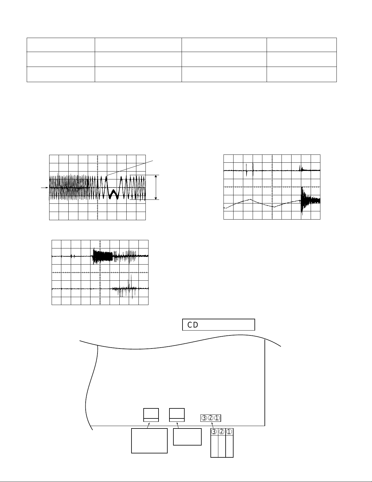
CD SECTION
1. This CD unit need adjustment as follow.
CD Test Mode
Step 1 VR803 (Focus Offset) DC + 40 mV (FEI>RFO) FEI (R826) and VRO
Step 4 VR802 (Tracking Error Balance) *1 (See Fig. 10-1) TSO (3-Pin of TP801)
*1: Adjust to obtaiin vertically symmetrical waveform (Fig. 10-1) with respect toreference DC level. The reference level is VRO
(Approx DC 2.1V).
2. This CD unit have the following automatic adjustment function. Automatic adjustment item.
2-1: Focus Servo Gain (Fig. 10-2)
Focus Gain Adjustment is performed when disc is changed.
2-2: Tracking Servo Gain (Fig. 10-3)
Tracking Gain Adjustment is performed when disc is changed and disc is playbacked.
VRO
Adjustment Part
TSO
1
SYMMETRICAL
UP AND DOWN
Value/Adjusting Method
FEI
Instrument Connection
(1-Pin of TP801)
and VRO (1 Pin of TP801)
1
TSO
TS2O
Figure 10-1
Figure 10-3
FSO
Figure 10-2
1
2
2
CD SERVO PWB
VR802 VR803
TP801
321
TRACKING
ERROR
FOCUS
OFFSET
BALANCE
Figure 10-4 ADJUSTMENT POINTS
– 10 –
321
T
S
O
V
N
R
C
O
XL-505/505C,CP-505B
TEST MODE
The Test Mode for this microcomputer has two variations, namely "regular Test Mode" for adjustment and measurement and "selfdiagnosis Test Mode" for self-judgment in final inspection of products.
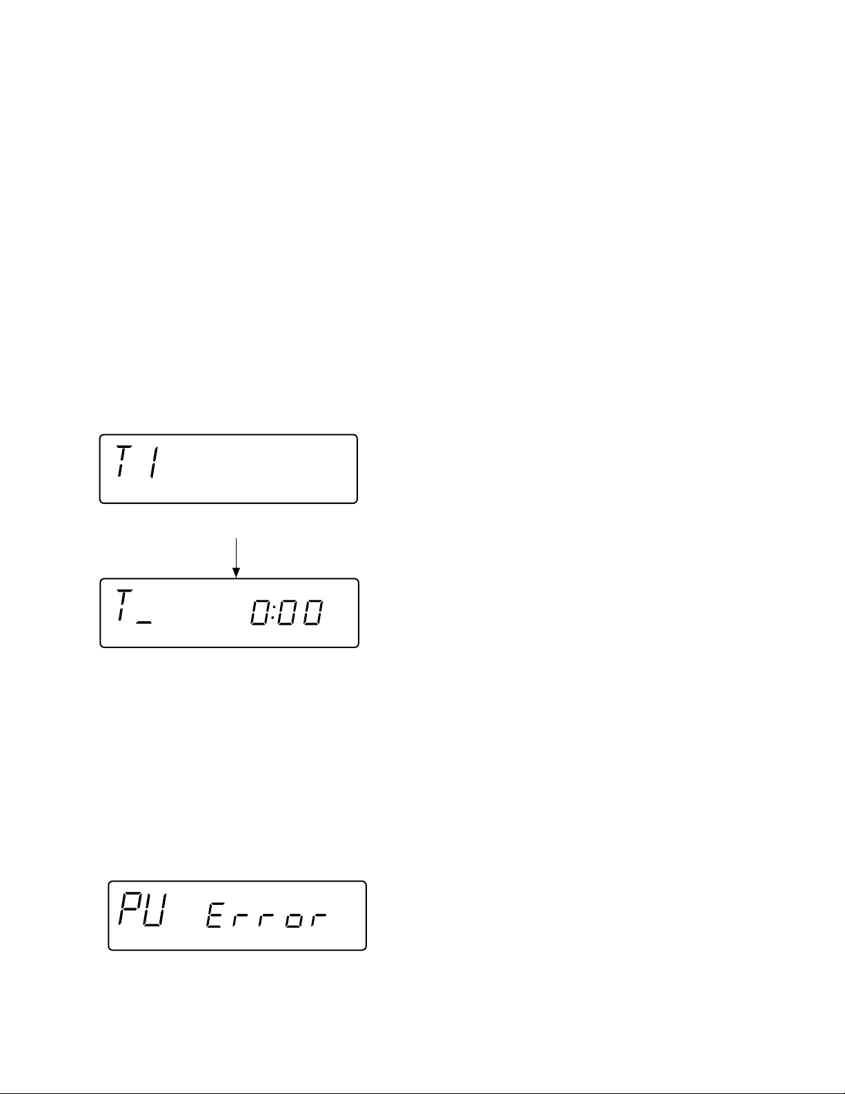
1. Entering the Test Mode
To enter the each Test Mode, press the POWER key, holding down the following two keys in the regular standby mode (power
off state). In this case only the main unit keys are valid. The Test Mode is not set even when the remote controller POWER
key is turned on.
[Regular Test Mode] [Holding Down Keys]
1. CD Test Mode (TEST 1) ................................... Stop + Play
2. Tuner Test Mode (TEST 3)................................ Memory/Set + Band Selector
3. Electronic volume Test Mode (TEST 4) ............ Stop + Extra Bass/Equalizer Mode
4. Timer Test Mode (TEST 5) ................................ Fast Forward + Function Selector
5. LCD Test Mode (TEST 6) .................................. Memory/Set + Function Selector
[Self-diagnosis Test Mode]
1. Key input diagnosis TEST Mode (TESTA) ........ Play + Record Pause
2. CD Test Mode (TEST 1)
1. Step 1 Mode
When the CD Test Mode is set, the following display lights, and the CD pickup slides to the innermost periphery.
After lighting for 1.5 sec
When the following operation key is pressed in this state, the following operation is performed.
"POWER" ................The Test Mode is set to off, power is turned off, and the mode is changed to the regular standby mode.
"FF/FWD" ................After the pickup returns once to the innermost periphery, the pickup slides to the external periphery while
.................................this key is held down.
"REW/REV" .............After the pickup returns once to the innermost periphery, the pickup slides to the internal periphery while
.................................this key is held down. However, input is invalid if PU-IN is on.
"PLAY".....................Shift to Step 2
"STOP" ....................Invalid
* In case of mode entry the pickup is moved to the internal periphery. At this time entry of any key other than POWER key is
disabled until shift of pickup to the internal periphery is completed. If PU-IN SW ON cannot be detected while waiting for 10
seconds, the slide motor is stopped, the following error is displayed, and entry of any key other than POWER key is disabled.
– 11 –
XL-505/505C,CP-505B
2. Step 2 Mode
When the PLAY key is pressed in the mode above, the laser lighting is turned on. In this state the laser is only turned on,
and other operations are not performed.
When the following operation key is pressed in this state, the following operation is performed.
"POWER" ................The Test Mode is set to off, power is turned off, and the mode is changed to the regular standby mode.
"FF/FWD" ................While this key is held down, the pickup slides to the external periphery.
"REW/REV" .............While this key is held down, the pickup slides to the internal periphery. However, if PU-IN is on, entry is
.................................invalid.
"PLAY".....................Shift to Step 3
"STOP" ....................Return to Step 1
3. Step 3 Mode
While the laser is lighting, the focus servo is turned on, and focus search is performed. If focusing failure occurs, focus search
is repeated until focusing is attained.
When the following operation keys are pressed in this state, the following operations are performed.
"POWER" ................The Test Mode is set to off, power is turned off, and the mode is changed to the regular standby mode.
"FF/FWD" ................While this key is held down, the pickup slides to the external periphery.
"REW/REV" .............While this key is held down, the pickup slides to the internal periphery. However, if PU-IN is on, entry is
.................................invalid.
"PLAY".....................If focusing has been attained, the process proceeds to Step 4. Unless focusing has been attained,
.................................reception is inhibited.
"STOP" ....................Return to Step 1
4. Step 4 Mode
The disc is rotated and CLV is locked while the tracking servo is off.
The time display indicates always "0:00".
When the following operation keys are pressed in this state, thefollowing operations are performed.
"POWER" ................The Test Mode is set to off, power is turned off, and the mode is changed to the regular standby mode.
"FF/FWD" ................While this key is held down, the pickup slides to the external periphery.
"REW/REV" .............While this key is pressed, the pickup slides to the internal periphery. However, if PU-IN is on, entry is
.................................invalid.
"PLAY".....................Shift to Step 5
"STOP" ....................Return to Step 1
– 12 –
XL-505/505C,CP-505B
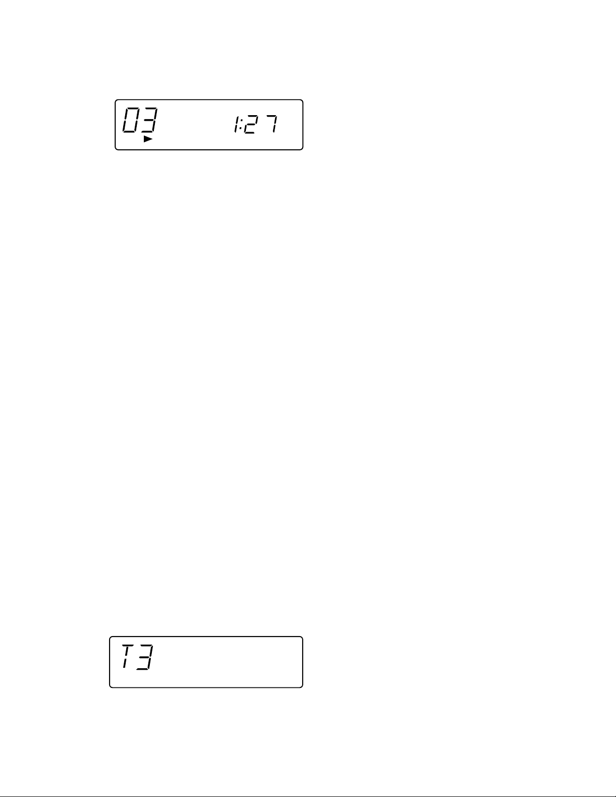
5. Step 5 Mode
The tracking servo is turned on, groove is traced, mute is set to off, and playback is started. Even when the outermost
periphery of disc is reached in playback mode, it does not stop. The LCD display indicates playback lapse time as in case
of regular CD playback.
When the following operation keys are pressed in this state, the following operations are performed.
"POWER" ................The Test Mode is set to off, power is turned off, and the mode is changed to the regular standby mode.
"FF/FWD" ................While this key is held down, the pickup slides to the external periphery.
"REW/REV" .............While this key is held down, the pickup slides to the internal periphery. However, if PU-IN is on, entry is
.................................invalid.
"PLAY".....................Invalid
"STOP" ....................Return to Step 1
Other cautions
• While the CD lid OPEN is detected, entry into any step later than Step 2 is disabled. If CD lid OPEN is detected in any step
higher than Step 2, return to Step 1 is done.
• TOC IL is not performed in the Test Mode.
• The key operation, excepting that specified above, is the same as that of regular operation (CD). Only the FUNCTION key
is input-inhibited.
• Syncro REC with REC key input is also invalid in this mode.
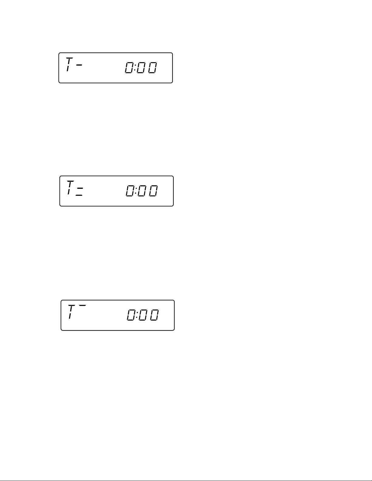
3. Tuner Test Mode (TEST 3)
1. Outline of tuner (radio) Test Mode
The tuner Test Mode is intended to store adjustment/measurement frequency in the preset memory CH without frequency
adjustment by the adjusting personnel when the tuner is adjusted in the production line.
2. Details of tuner Test Mode
When power is turned on with the POWER key while the MEMORY/SET key and BAND key are held down together in
POWER OFF state, the frequency for adjustment/measurement of specific destination specified by the AREA terminal is
preset-stored in the preset memory CH (the frequency to be preset-stored for specific destination is explained in the Item
C). When the tuner Test Mode is started up, it is started with FM. FM is FM STEREO only.
When the REW key is pressed while the preset memory CH is 1CH, the highest CH is found as in case of regular mode. When
the FF key is pressed while the preset memory CH is highest CH, 1CH is found.
The RADIO (TUNER) BAND key (or TUNER/BAND key on the remote controller) is valid.
As in case of regular mode, selection of band, FM MONO/STEREO mode is enabled by pressing the RADIO (TUNER) BAND
(or TUNER/BAND ) key.
Exiting the tuner Test Mode, When the destruction data is stored in the memory in the tuner Test Mode, AC supply is
interrupted in the Test Mode and the AC supply is recovered, all the memory is cleared with the destruction data in case of
start-up.
(Countermeasures so that the Test Mode memory does not remain when AC supply is restored after power supply failure
occurred once in the Test Mode.) The memory is not cleared when AC supply is turned off after POWER OFF and FUNCTION
selection. In case of exit from the tuner Test Mode through the backup mode upon occurrence of power failure
the frequency data stored in the preset memory for adjustment/measurement is erased. (As a result the preset
memory CH becomes empty.)
The display indication is the same as that in case of regular operation.
The following display lights for one second when the tuner TEST mode is turned on
– 13 –
XL-505/505C,CP-505B
Test Mode operation specification
3. Preset frequencies for various destinations (random preset memory)
BAND (CH)
1 FM 87.5MHz
2 FM 108.0MHz
3 FM 98.0MHz
4 FM 90.0MHz
5 FM 106.0MHz
6 AM 530 kHz
7 AM 1720 kHz
8 AM 990 kHz
9 AM 600 kHz
10 AM 1400 kHz
• The unit used in the table above is Hz. K represents 1,000 times, and M represents 1,000,000 times.
• The hatched data shown in the table are not stored in the memory.
• FM is stereo mode.
Note: Keys which are effective in Test Mode
• Main unit keys: VOLUME UP/DOWN, BAND, TUNING UP, POWER, MEMORY, CLEAR,
PRESET UP/DOWN
• Remote controller keys:
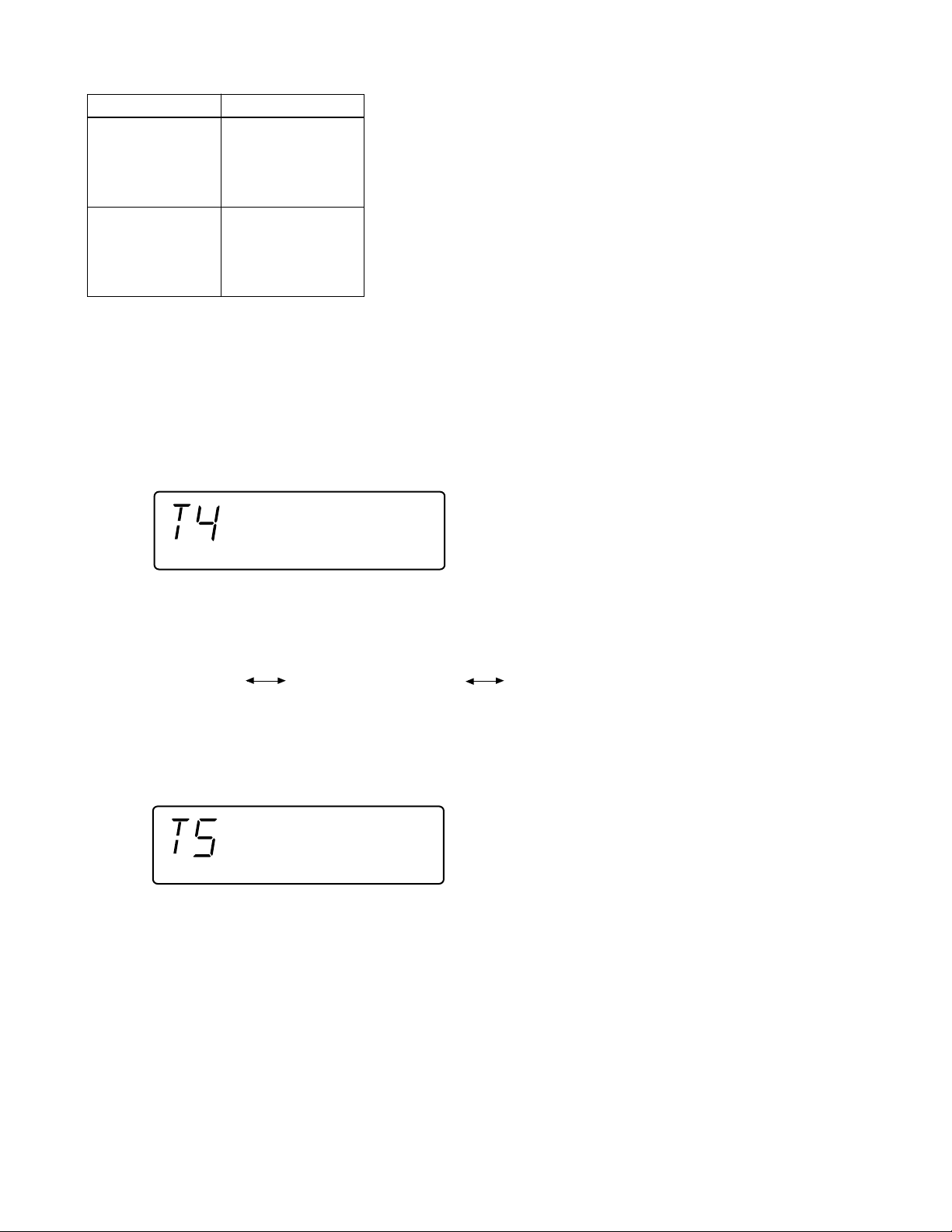
4. Electronic volume Test Mode (TEST 4)
After the Test Mode is set, the following display lights for one second.
VOL UP/DOWN, BAND, TUNING UP/DOWN, POWER, MEMORY, CLEAR, PRESET UP/DOWN
When this mode has been set, -14dB (STEP17) is set, the preset equalizer is set to FLAT (EQ-3), the SRS mode is set to OFF,
and the start-up function is set to Tape.
1. The display is the same as that indicated in case of regular operation excepting when Test Mode is set.
2. The volume control with the Volume UP/DOWN key is only the following 3 steps, differing from the volume control in the regular
operation mode.
Volume — ∞ (STEP 0) Volume — 14dB (STEP 17) Volume — 0 (STEP 24)
3. The preset equalizer and SRS are switched if key operation is performed.
5. Timer Test Mode (TEST 5)
When the Test Mode is set, the following display lights for one second.
The current time and timer time are set in the following procedure, and timer playback is performed.
1. The present time is set to 1:00, the timer is set to ON time 1:02, OFF time 1:12, Function is set to Tape, Volume is set to STEP8.
One minute is counted in increments of second, and timer playback is performed. One step of Fade-in/out in this mode is
performed for 0.5 sec.
The display is the same as that appears in the regular timer operation.
2. After completion of timer playback test "TEST-5" indication (which appears when the mode is set) appears again and Standby
state is set. PLAY key entry is waited. If an entry is detected, the SLEEP timer is set to 2 minutes, and Function is set to
Tape, so that playback is started at once. Volume is set to STEP8, and 10 seconds are counted down in decrements of
second. One step of Fade-out is 0.5 sec.
The display is the same as that appears in the regular sleep playback mode.
3. After completion of SLEEP test, the Test Mode is turned off, and regular standby mode is set, so that the Test Mode ends.
– 14 –

XL-505/505C,CP-505B
6. LCD Test Mode (TEST 6)
When the LCD Test Mode is set, all the LCD segments light.
7. Key input diagnosis Test Mode (TEST A)
When the Test Mode is set, the following display appears.
In this Test Mode checking as to whether all the main unit keys can be detected is performed. Accordingly, when this mode
is set, checking is performed so as to examine whether the POWER key was pressed last after all the following keys were
pressed. If the result is OK, the following OK is displayed. If any one of keys was not pressed, an error is indicated. When the
POWER key is pressed, exit from the mode is made irrespective of whether the termination is normal or abnormal, and the
standby mode is set.
All the models using this microcomputer do not have the same keys. The entry of the following keys is detected depending on
the combination of simultaneously pressed keys when this mode is set. Key pressing order is not fixed. Pressing of all keys
must be detected.
1. In case of "PLAY" + "REC PAUSE"
Since the model does not have RDS and SRS, all the keys to be detected are the following 11 keys.
PLAY, VOL , VOL , BAND, G-EQ, FUNCTION, MEMORY/SET, REC PAUSE, REW/REV, FF/FWD, STOP
<
<
OK/NG indication of test result must be as follows.
NG indication
OK indication
– 15 –

XL-505/505C,CP-505B
TSO
LED704-LED712
FW701
SWITCHING
Q701
RESET
Q702
Q703
µ-CON +5V
RX701
321
KEY
SW702-SW707
SW710-SW714
SW718
X701
8MHz
X702
32.768KHz
SYS STOP
REMOCON
RESET
M+12V
Q704 Q705
SWTCHING
LCD
LCD701
~
COM3
1
~
~
4
COM0
5
VLC3
9
OSC2
10
OSC1
11
VSS
XI
12
13
XO
14
MMOD
15
VREF
17
KEY1
~
~
19
POWER
21
F.P
~
~
23
CAM SW
~
DI
CE
25 31 32 34 35 36 37 38 39 40 41 45 46 47 48
~
IC701
IX0189AW
SYSTEM
MICROCOMPUTER
P-CONT
P-MUTE
RESET
CD+B
REMOCON
CLE
SYS STOP
SEG7
STEREO
FW702
7493
~
SEG26
62
BUS3
~
~
57
PU-IN
56
LID-SW
55
BIAS
54
B-CAN
53
REC
52
MOT
CEE
BUCK
R-MUTE
SOL
51
SD
CD RES
IC804 : FOCUS/TRACKING/
TR+
FO+
FO–
TR–
ACTUATOR
1/2VCC
C
F
B
A
E
GND
MON
LD
VCC
SL+
SL–
18 17 16 15 14 13 12 11 10
NC
VCC
Reg5V
–
+
–
+
–
+
19 20 21 22 23 24 25 26 27
SPIN/SLIDE DRIVER
LEVEL
SHIFT
LEVEL
SHIFT
– –
++
–
++
––
987654321
GND
+
GND
28 29 30 31 32 33 34 35 36
DMEO
SP+
SP–
+
SP+
M
SP–
–
SL+
+
SL–
M
PU-IN
–
GND
TR–
1
TR+
2
FO+
3
FO–
4
GND
5
PD
6
VR
7
LD
8
C
1
F
2
B
3
A
4
E
5
1/2V
6
+5V
7
SPINDLE
C4A
M801
SLED
M802
SW801
PU-IN
VR1A
C2A C3A
SWITCHING
TR–
TR+
––
++
LEVEL
SHIFT
LEVEL
SHIFT
++
––
VCC
FO+
FO–
6
6
5
5
4
4
3
3
2
2
1
1
CNP803
CNS803
CNS801
11
55
CNS802
11
55
GAIN1
–
+
–
+
GAIN4
FSO
6
5
4
3
2
1
22
33
44
66
77
88
22
33
44
66
77
FMSO
TS2O
NC
STAND
BI803
BI801
BI802
T.S.D
Q707
-BY
GND
TR–
TR+
FO+
FO–
GND
PD
VR
LD
+–
PU-IN
1/2VCC
+5V
A 12V
LED+B
IC804
M56748FP
CD STB
SP+
SP–
SL+
SL–
P CONT
Q706
SWITCHING
SWTCHING
+5V
Q801
Figure 16 BLOCK DIAGRAM (1/4)
– 16 –
DMEN
TPI
DMEP
TNI
TRACKING
ERROR
BLANCE
VR802
SEL
TNO
DMEO
DFCT
25
FMSO
26
FMSM
27
FMSP
28
THLD
29
TS2O
30
TS2N
31
TS2P
32
TS1N
33
TS1P
34
TSO
35
TEL1
36
TEL2
37
TSN
38
39 40 41 42 43 44 45 46 47 48
TPO
LDO
PD
CD+5V
VCC
FNI
GND
OSCI
FPI
LDO
COSC
MDI
15161718192021222324
FSO
FSN
RFT
RFN
SERVO AMP.
14
FEL2
13
FEL1
12
FHLD
FEI
11
10
FEO
FEN
9
FEP
8
DFIN
7
SBAD
6
RFRP
5
2VRO
4
VRO
3
RFI
2
RFO
1
IC801
TA2065F
FOCUS
OFFSET
VR803
TE
 Loading...