

SONY
3-754-157- 13 (2)
CCD Color Video Camera Module

Operating Instructions page 2
Before operating the unit, please read this manual thoroughly and retain it for future reference.
取扱説明書 33ページ
お買い上げいただき、ありがとうございます。 お使いになる前に、この取扱説明書をお読みください。 お読みになったあとは、後日お役に立つこともありますので、 必ず保存してください。
© 1991 by Sony Corporation
Owner's Record
Model No. _____ Serial No. _____
WARNING
To prevent fire or shock hazard, do not expose the unit to rain or moisture.
(servicing) instructions in the literature accompanying the appliance.
WARNING
WARNING This equipment generates, uses, and can radiate radio frequency energy and if not installed and used in accordance with the instructions manual, may cause interference to radio communications. It has been tested and found to comply with the limits for Class A computing devices pursuant to Subpart J of Part 15 of FCC Rules, which are designed to provide reasonable protection against such interference when operated in a commercial environment. Operation of this equipment in a residential area is likely to cause interference in which case the user at his own expense will be required to take whatever measures may be required to correct the interference.
The shielded interface cable recommended in this manual must be used with this equipment in order to comply with the limits for computing device pursuant to Subpart J of Part 15 of FCC Rules.
For customers in Canada
Pour les utillisateurs au Canada
r our les unitisateurs au Canada Cet appareil est conforme aux normes Classe A pour bruits radioélectriques, spécifiés dans le Réglement sur le brouillage radioélectrique.
Bescheinigung des Herstellers Hiermit wird bescheinigt, daß der CCD-Videokameramodul XC-999P in Übereinstimmung mit den Bestimmungen der Amtsblattverfügung Nr. 1046/1984 funkentstört ist. Der Deutschen Bundespost wurde das Inverkehtbringen dieses Gerätes angezeigt und die Berechtigung zur Überprüfung der Serie auf Einhaltung der Bestimmungen eingeräumt. Sony Corporation
Hinweis Gemäß dem Amtsblatt des Bundersministers für das Post-und Fernmeldewesen Nr. 163/1994 wird der Betreiber darauf aufmerksam gemacht, daß die von ihm mit diesem Gerät zusammengestellte Anlage auch den technischen Bestimmungen dieses Amtsblattes genügen muß.
English Table of Contents
| Ta atoma a | |
|---|---|
| reatures | |
| Special Accessories (not Supplied) | 1 |
| Precautions | ' |
| Location and Function of Parts | 3 |
| XC-999/999P CCD Color Video Camera | |
| Module | 3 |
| CMA-999/999P RGB Adaptor | 1 |
| Installation | 1 |
| Usable Lens | 1 |
| Attaching the Lens | 1 |
| Installing the Camera | 2 |
| Connections | 2 |
| When Using the Camera with the | |
| JB-77 Junction Box | 2 |
| When Using the Camera with the | |
| CMA-999/999P RGB Adaptor | 2 |
| When Using the Camera with the | |
| DC-77RR/77RR-CE Camera Adaptor | 2 |
| CCD Special Characteristics | 2 |
| Specifications | 2 |
| Accessories not supplied |
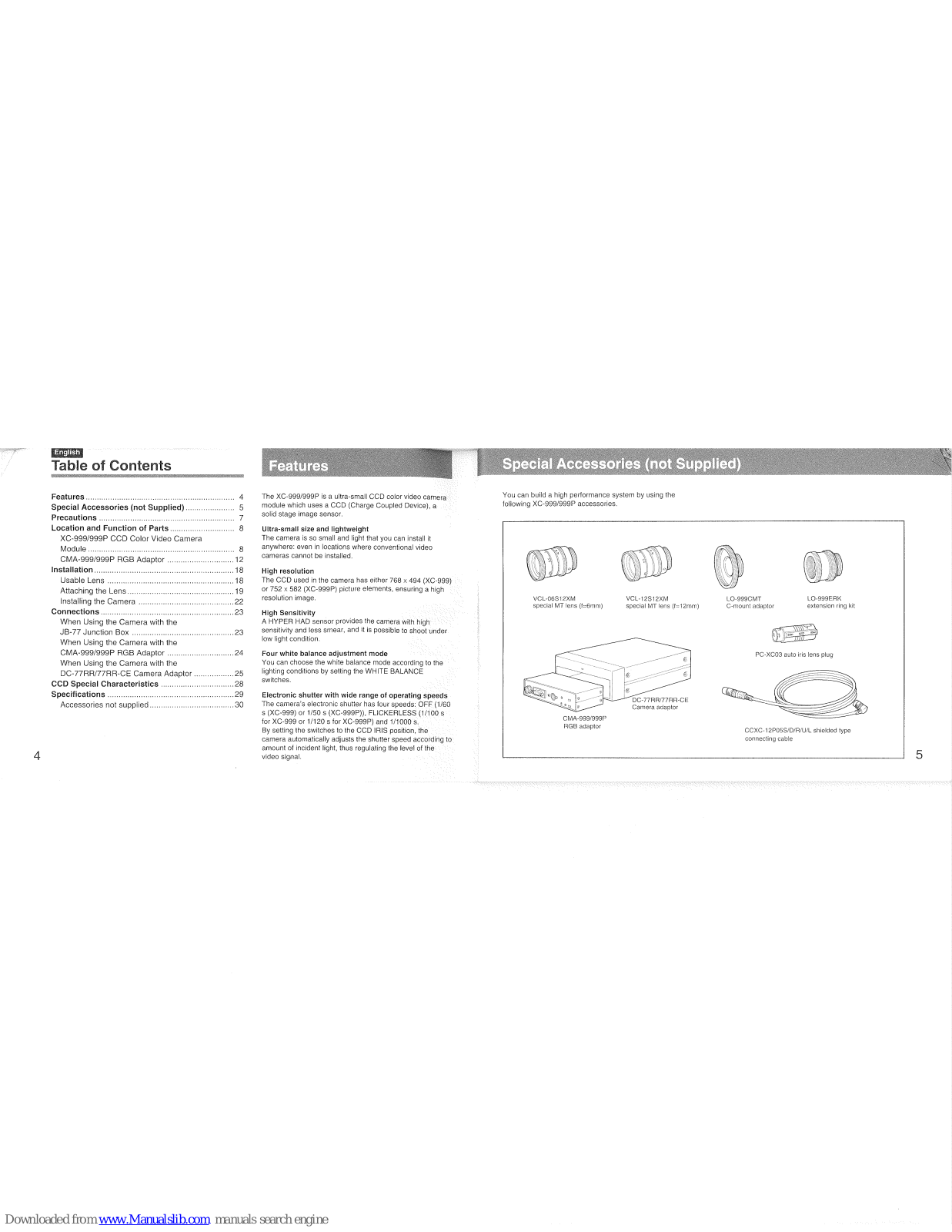
Features
The XC-999/999P is a ultra-small CCD color video camera module which uses a CCD (Charge Coupled Device), a solid stage image sensor.
Ultra-small size and lightweight The camera is so small and light that you can install it anywhere: even in locations where conventional video cameras cannot be installed.
High resolution The CCD used in the camera has either 768 × 494 (XC-999) or 752 × 582 (XC-999P) picture elements, ensuring a high
High Sensitivity A HYPER HAD sensor provides the camera with high sensitivity and less smear, and it is possible to shoot under low light condition.
Four white balance adjustment mode You can choose the white balance mode according to the lighting conditions by setting the WHITE BALANCE switches.
Electronic shutter with wide range of operating speeds The camera's electronic shrutter has four speeds: OFF (1/60 s (XC-999) or 1/50 s (XC-999P)), FLICKERLESS (1/100 s for XC-999 or 1/20 s for XC-999P) and 1/1000 s. By setting the switches to the CCD IRIS position, the camera automatically adjusts the shutter speed according to amount of incident light, thus regulating the level of the video signal.
Special Accessories (not Supplied)
You can build a high performance system by using the following XC-999/999P accessories.

CCMA-999/999P RGB adaptor The RGB adaptor provides the following functions. • RGB output function (D-SUB 9-pin) and Y (luminance)/C (chrominance) output (Y/C separated output connector) function • Canlock function • Exposure time control function You can use this adaptor together with either of the DC-77RR/77RR-CE or the JB-77.
VCL-12S12XM special MT lens (f=12mm) VCL-06S12XM special MT lens (f=6mm) Manual tris lens specially designed for use with the XC-999/ 999P.
LO-999CMT C-mount adaptor
Lens mount adaptor designed for mounting conventional C mount lens onto the XC-999/999P.
LO-999 ERK extension ring kit Extension ring kit designed for the XC-999/999P Color video
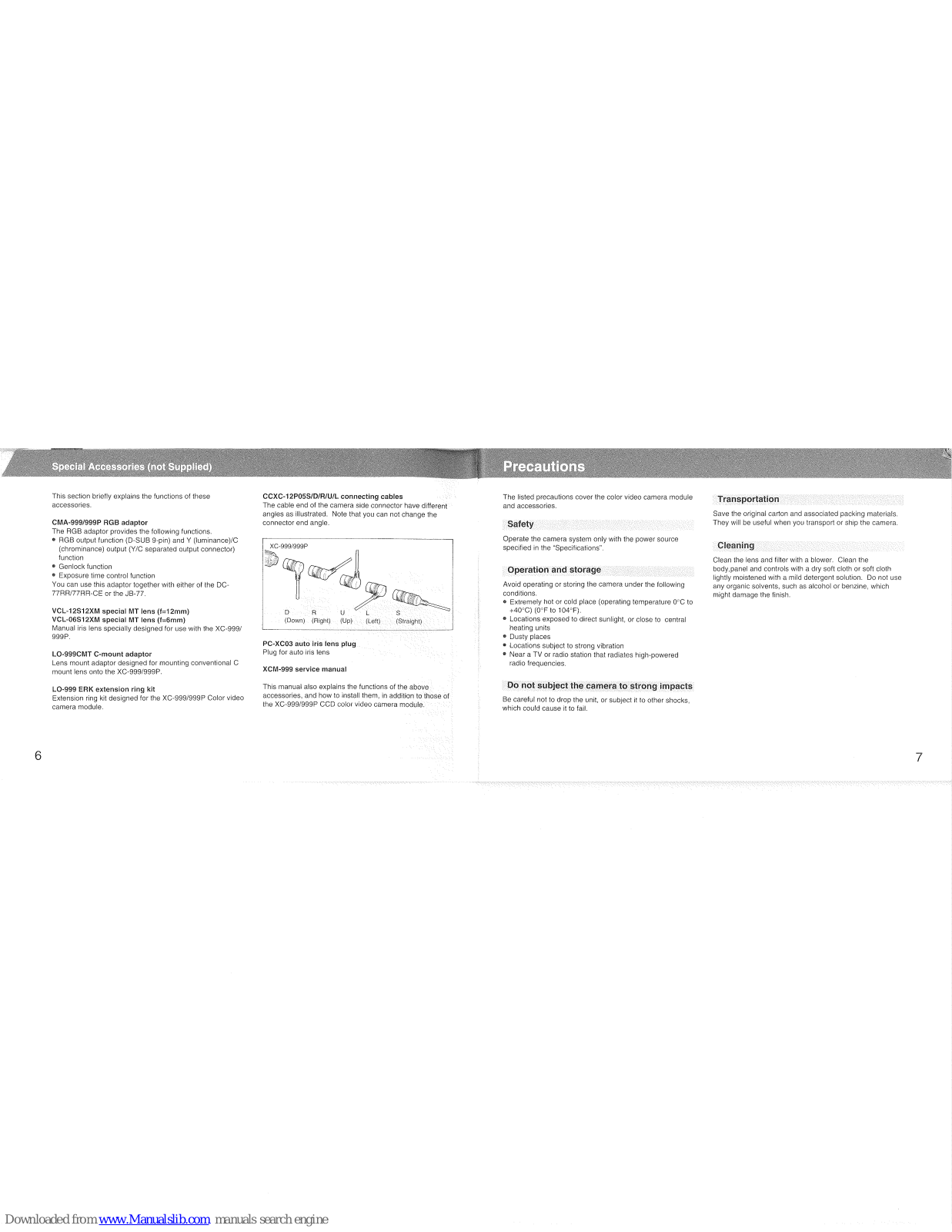
CCXC-12P05S/D/R/U/L connecting cables The cable end of the camera side connector have different angles as illustrated. Note that you can not change the connector end angle.
| AC-999/999P | |
|---|---|
| state Maso | |
| U 🔊 | Callon - |
| DRU C L | s |
| (Down) (Right) (Up) (Left) | (Straight) |
PC-XC03 auto iris lens plug Plug for auto iris lens
XCM-999 service manual
Safety
Operation and storage
+40°C) (0°F to 104°F). • Locations exposed to direct sunlight, or close to central heating units • Dusty places
- Locations subject to strong vibration Near a TV or radio station that radiates high-powered
Do not subject the camera to strong impacts
Transportation
Cleaning

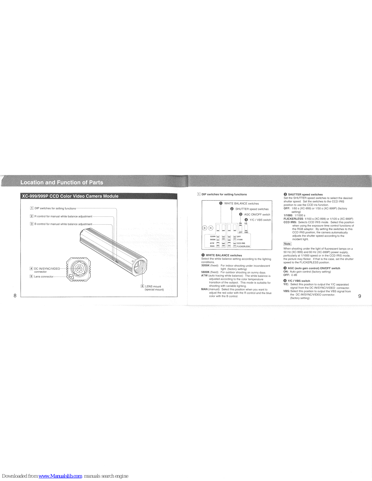
1 DIP switches for setting functions

Select the white balance sering reverses of conditions. 3200K (lixed): For indoor shooting under incandescent light. (factory setting) 5600K (lixed): For outdoor shooting on sunny days. 570W (such tracing white balance): The white balance is
ATW (auto tracing while balance): The while balance is adjusted according to the color temperature transition of the subject. This mode is suitable for shooting with variable lighting.MAN (manual): Select this position when you want to adjust the red color with the R control and the blue color with the B control.
SHUTTER speed switches Set the SHUTTER speed switches to select the desired shutter speed. Set the switches to the CCD IRIS position to use the CCD iris function. OFF: 1/60 s (XC-999) or 1/50 s (XC-999P) (factory setting) 1/1000 s FLICKERLESS: 1/100 s (XC-999) or 1/120 s (XC-999P) CCD IRIS: Selects CCD IRIS mode. Select this position when using the exposure time control functions of the RGB adaptor. By setting the switches to this CCD IRIS the shutter speed according to the incident light.
Note
[Note] When shooting under the light of fluorescent lamps on a 50 Hz (XC-999) and 60 Hz (XC-999P) power supply, particularly at 1/1000 speed or in the CCD IRIS mode, the picture may licker. If that is the case, set the shutter speed to the FLICKERLESS position.
AGC (auto gain control) ON/OFF switch ON: Auto gain control (factory setting) OFF: 0.1
OFF: 0 dB () Y(C / VBS switch Y/C: Select this position to output the Y/C separated signal from the DC IN/SYNC///DEO connector. VBS: Select this position to output the VBS signal from the DC IN/SYNC///DEO connector.
Location and Function of Parts
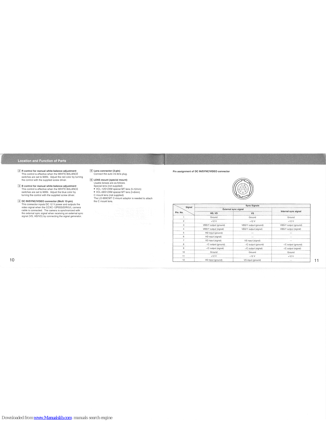
- [2] R control for manual white balance adjustment This control is effective when the WHITE BALANCE switches are set to MAN. Adjust the red color by turning the control with the supplied screw driver.
- 3 B control for manual white balance adjustment This control is effective when the WHITE BALANCE switches are set to MAN. Adjust the blue color by turning the control with the supplied screw driver.
- [4] DC IN/SYNC/VIDEO connector (Multi 12-pin) This connector inputs DC 12 V power and outputs the video signal when the CCXC-12P05S/D/R/U/L camera cable is connected. The camera is synchronized with the external sync signal when receiving an external sync signal (VS, HD/VD) by connecting the signal generator.
5 Lens connector (3-pin) Connect the auto iris lens plug.
Connect the auto inis lens plug. (a) LENS mount (special mount) Usable lenses are as follows. Special lens (not supplied) • VCL-12S12XM special MT lens (l=12mm) • VCL-06S12XM special MT lens (l=6mm) C mount lens (not supplied) The LO-99CMT C-mount adaptor is needed to attach the C mount lens.
Pin assignment of DC IN/SYNC/VIDEO connector

| Ginnal | Sync Signals | |||
|---|---|---|---|---|
| Signal | External s | Internal score stored | ||
| Pin. No. | HD, VD | VS | internai sync signai | |
| 1 | Ground | Ground | Ground | |
| 2 | +12 V | +12 V | +12 V | |
| 3 | VBS/Y output (ground) | VBS/Y output (ground) | VBS/Y output (ground) | |
| 4 | VBS/Y output (signal) | VBS/Y output (signal) | VBS/Y output (signal) | |
| 5 | HD input (ground) | |||
| 6 | HD input (signal) | _ | ||
| 7 | VD input (signal) | VS input (signal) | ||
| 8 | -/C output (ground) | -/C output (ground) | -/C output (ground) | |
| 9 | -/C output (signal) | /C output (signal) | -/C output (signal) | |
| 10 | Ground | Ground | Ground | |
| 11 | +12 V | +12 V | +12 V | |
| 12 | VD input (ground) | VS input (ground) | ||

Y/C connector (4-pin) Use the YC-15EV connecting cable (not supplied) for connection.
Pin assignmer


RGB/SYNC connector (D-SUB 9-pin) This connector outputs the RGB signal. Use the CCXC-9DB/CCXC-9DD connecting cables (not supplied) for
Pin assignment of RGB/SYNC connector

| Pin no. | Signal |
|---|---|
| 1 | Ground |
| 2 | Ground |
| 3 | RED output |
| 4 | GREEN output |
| 5 | BLUE output |
| 6 | VBS(Y) output |
| 7 | SYNC(HD) output |
| 8 | NC(HD input) |
Tread the service manual (not supplied). CAMERA connector (12 pin) Connect to the XC-999/999P CCD color video camera module
[4] SC phase control, H phase control and subcarrier

Subcarrier phase switch
Subcarrier phase switch Set this switch so that the subcarrier phase difference between the genlock input and video output signals is 0°
SC (subcarrier) phase control Use this control for fine adjustment of the subcarrier phase after making a rough adjustment with the subcarrier phase switch.
I (horizontal) phase control Use this control to adjust the H phase difference between the genlock input and video output signals.
between the genlock input and video output signals. Adjust the subcarrier phase and horizontal phase by following the procedure below. Subcarrier phase adjustment Adjust the subcarrier phase roughly by setting the subcarrier phase switch to 0° or 180° so that the phase difference between the genlock input and video output signals is 0° or 180°. Then, make the fine adjustment by using the SC control. Using a vectorscope will allow you to make more accurate adjustment.
Horizontal phase adjustment Adjust the horizontal phase with the H control. A waveform monitor or an oscilloscope will allow you to make the adjustment more easily.
EXPOSURE TIME CONTROL switch CCD IRIS: Select this position so that the camera automatically adjusts the exposure time. MAN: Select this position to adjust the exposure time with the exposure time control. When you set the switch to either of the above positions set the SHUTTER speed switches of the XC-999/999P color camera module to CCD IRIS.
[6] Exposure time control This switch works only when the EXPOSURE TIME CONTROL switch is set to MAN. The shutter speed can be adjusted by adjusting the exposure time.
Downloaded from www.Manualslib.com manuals search engine
Location and Function of Parts
<complex-block> Image: Instruction of the Contract of the Contr
Downloaded from www.Manualslib.com manuals search engine
Usable lens
Special lens (not supplied) • VCL-12S12XM special MT lens (f=12mm) • VCL-06S12XM special MT lens (f=6mm)

Note
[Note] This camera uses a 1/2-inch CCD, so the lens should be intended for use with this size of CCD. In particular, if used with a lens intended for a 2/3-inch CCD, the angle of view will be different.

Notes
The plug is very small and fragile. Take special when handling it.
Do not pull the lens cord connected to the lens adaptor. If so, the plug or camera lens connector may be damaged.

Installation
Replacing the lens cable plug with the PC-XC03 auto iris lens plug (not supplied)
Notes
(Notes) When handling or soldering, treat the plug very careful When soldering the wires to the plug pins, solder them with a soldering iron temperature of less than 280°C (540°F). Perform the soldering quickly within three seconds.

- 1 Remove the plug from the lens cable. Place the heat shurinkable tube over the lens cable.
- 2 Solder the shielded wire onto the inside of the shell as illustrated.
- 3 Solder the cable wires to the pins of the plug. (To identify the cable wires, refer to the manual for your lens.)
Note
- 4 After soldering, slide the heat shrinkable tube up agaist the terminal block. Secure the wires by heating the heat shrinkable tube with a soldering iron or dryer.
Installing the Camera
Connections
Turn off the units to be connected, or the compone the units may be damaged. To disconnect the cord, pull it out by the plug. Nev the cord itself. Connect the power cord after completing all other.
23


When Using the Camera with the DC-77RR/77RR-CE Camera Adaptor
Before connection Install the CMA-999/999P RGB adaptor into the camera adaptor. For details, see the instruction manual for the DC-77RP/77RP-CE camera adaptor.
Votes j Set the 75 Ω termination switch of the RGB adaptor to OFF. Insert the RGB adaptor into the camera adaptor firmly so that the DC IN/SYNC/VIDEO connector of the RGB adaptor is connected securely to the connector of the camera adaptor.
Connection Make sure that the 75 Ω termination switch of the RGB adaptor is set to OFF.
Connections

The RGB adaptor is connected to the camera adaptor. Fix the RGB adaptor and the camera adaptor at the bottom of the camera adaptor by using two screws. Refer to the instruction manual of the DC-77RR/77RR-CE for detailed explanation of installing the RGB adaptor into the camera adaptor.
Genlock
Centrock The color video camera module is designed so that internal sync and external sync are switched automatically. When the color video camera module receives the following external sync signal. the camera is synchronized to that external sync signal.
| Connection example | External sync signal | ||
|---|---|---|---|
| HD/VD | vs | VBS | |
| XC-999/999P - JB-77 | Genl | lock | No genlock |
|
XC-999/999P - CMA-999/
999P - JB-77 |
Genlock | ||
|
XC-999/999P - CMA-999/
999P - DC-77RR/77RR-CE |
Genlock | ||
CCD Special Characteristics
The following conditions that may be observed during the use of a CCD video camera are not associated with any fault of the camera:
Smearing The picture may be smeared when a very bright object is
Patterned noise This may appear over the entire monitor screen when the camera is operated at a high temperature.
Jagged picture When this stripes, straight lines, or the like are shot, the image monitored on the screen may appear jagged.
Sensitivity
Pickup device Pickup device Color filter Picture elements Interline transfer 1/2 inch CCD Complementary color mosaic filter XC-999: 768 (H) x 494 (V) XC-999: 752 (H) x 582 (V) 6.4 x 4.8 mm Optical and others Special mount Lens mount Special mount Signal system XC-999: TAL standard Accoupt: PAL standard XC-999: S25 lines, 2:1 interlace, 30 frames/s. Sync system XC-999: S25 lines, 2:1 interlace, 30 frames/s. Sync system Intermal/external (switched automatically) External sync signal HD/VD, VS XC-999: 470 TV lines XC-999P: 460 TV lines
4.5 lux, F1.2 AGC: ON 2000 lux F5.6 AGC: OFF (0 dB) VBS / Y/C (selected with the switch) VBS: 1 Vp-p, 75 ohms, sync negative Y: 1 Vp-p, 75 ohms C: C level depends on the composite video out signal
Video signal to noise ratio XC-999: more than 48 dB AGC: OFF (0d5) XC-999P: more than 46 dB AGC: OFF (0d6) Shutter speed 4 speeds selectable: OFF (1/60 s (XC-999) or 1/50 s (XC-999P)), 1/1000 s, CCD (RIS and flickerless 1/1000 s, CCD (RIS and flickerless 4 modes selectable: ATW (auto tracing white balance), 3200K, 5600K and MAN (manual) Gain control 2 modes selectable: AGC and fixed (0 dB) Output connector DC IN/SYNC/VIDEO: multi 12-pin LENS: 3-pin Power requirement 10.5 to 15 V DC Power consumption 3.5 W 3.5 W re 0°C to 40°C (32°F to 104°F) -20°C to 60°C (-4°F to 140°F) 80 % (no condensation permissible) 90 % (no condensation permissible) Less than 70°G (Wh/d) (1/8 x //8 x 4% inches) excluding projecting parts Abouf 99 (3 ½ o 2) 1 Tripod adaptor (1 set) Lens mount cap (1) Screw driver (1) Label (1) Storage temperature Operating humidity Storage humidity Shock resistance Dimensions Weight Accessories supplied
Specifications
Accessories not supplied
Camera adapto
| CMA-999/999P RGE | 3 adaptor |
|---|---|
| Specifications of the | CMA-999/999P are as follows. |
| Power requirement | 10.5 to 15 V DC |
| Power consumption | 4.5 W |
| Operating temperatu | ire |
| 0°C to 40°C (32°F to 104°F) | |
| Storage temperature | -20°C to 60°C (-4°F to 140°F) |
| Operating humidity | 80 % (no condensation permissible) |
| Storage humidity | 90 % (no condensation permissible) |
| Shock resistance | Less than 40G |
| Dimensions | 135.5 x 30 x 69 mm (w/h/d) |
| (5 3/6 x 1 3/16 x 2 3/4 inches) | |
| excluding projecting parts | |
| Weight | About 290 g (10 1/4 oz) |
| Camera adaptor | DC-77RR/77RR-CE |
| lunction hox | IB-77 |
Lens and lens accessories Special mount lens (f=12mm) VCL-05512XM special MT lens (f=6mm) C Mount adaptor Extension ring kit LO-999CMT Cables 12-pin camera cable Connecting cables CCXC-9DD (with D-SUB 9-pin connectors) CCXC-9DB (with D-SUB 9-pin and five BNC connectors) VC-15EV (with D14-pin connectors)
Design and specifications are subject to change without notice.
お問い合わせ
コンポーネント営業本部イメージセンシングブロダクツ営業部 カメラモジュール課 ソニー株式会社 厚木第2テクノロジーセンター 神奈川県厚木市岡田2255 〒243 Tel 0462-27-2346 Fax 0462-27-2347
ソニー株式会社 〒141 東京都品川区北品川6-7-35 Printed in Japan


 Loading...