

Page 1
AV Center
2-597-872-12(1)
Installation/Connections
Installation/Connexions
Instalación/Conexiones
Notice to dealers and installers
Please return this manual to the customer after the installation is completed.
Avis aux revendeurs et installateurs
Veuillez rendre ce manuel au client une fois l’installation achevée.
Aviso para los proveedores e instaladores
Una vez finalizada la instalación, devuelvan este manual al cliente.
US
FR
ES
XAV-A1
© 2005 Sony Corporation
Page 2

Precautions
Unit is designed for negative ground
12 V DC systems only
The unit cannot be used in trucks or other cars
with 24 V systems. Otherwise, there is a risk of fire
and damage.
Do not disassemble or remodel the
unit
This can cause electric shock, personal injury or
fire. Do not connect any other system’s power
supply cord to this unit’s power supply cord
directly. If you are in any doubt about the safe
installation of this unit, please consult your nearest
Sony dealer.
Do not install in locations which
interfere with airbag operation
Otherwise there is a risk of accidents and injury.
Use only the specified fuse
When replacing the fuse, be sure to use only a fuse
of the same rating (ampere rating). Otherwise
there is a risk of fire.
Cautions
• Do not get the wires under a screw, or caught in
moving parts (e.g. seat railing).
• Before making connections, turn the car ignition
off to avoid short circuits.
• Connect the yellow and red power input leads
only after all other leads have been connected.
• Run all ground wires to a common ground
point.
• Be sure to insulate any loose unconnected wires
with electrical tape for safety.
Notes on the power supply cord (yellow)
• When connecting this unit in combination with
other stereo components, the connected car
circuit’s rating must be higher than the sum of
each component’s fuse.
• When no car circuits are rated high enough,
connect the unit directly to the battery.
On safety
Comply with the Traffic Laws in your country.
2
Page 3

Table of Contents
Precautions...................................................................................................... 2
Parts List .......................................................................................................... 4
Connection Example....................................................................................... 5
Connecting Information ................................................................................. 6
Connecting the cords......................................................................................................... 6
Using the tap....................................................................................................................... 6
1 Car Systems Connections ......................................................................... 7
Connecting without optional TV tuner unit .................................................................. 9
Connecting with optional TV tuner unit ...................................................................... 10
2 Installing the Main Unit.......................................................................... 11
Before installation ............................................................................................................ 11
Removing the bracket .................................................................................................... 12
Installation procedure ..................................................................................................... 13
3 After Installation and Connections ........................................................ 15
3
Page 4
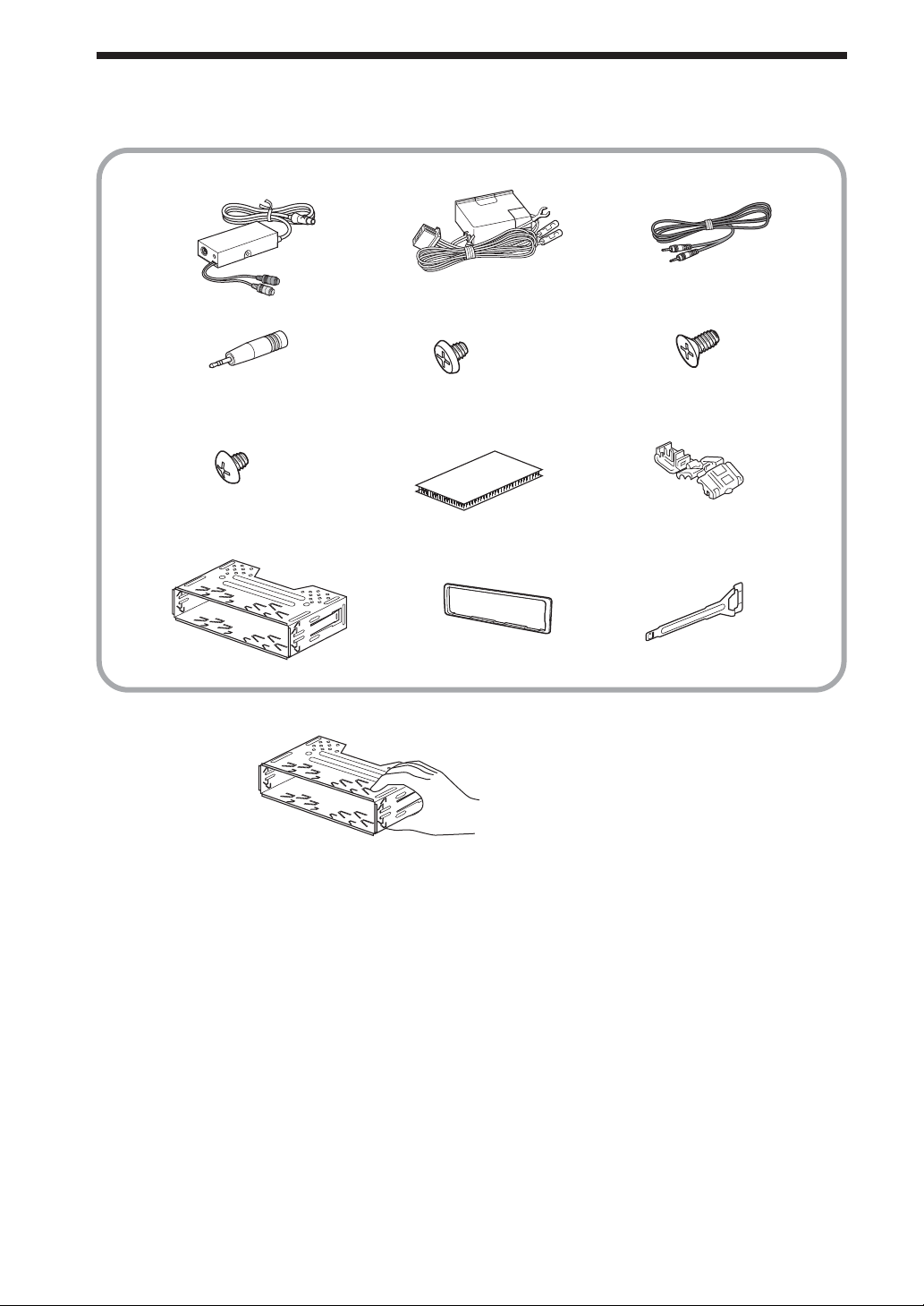
Parts List
The numbers in the list are keyed to those in the instructions.
123
456
×4
789
×4
q; qa qs
CAUTION
Handle the bracket
0 carefully to avoid
injuring your fingers.
×4
×2
4
Page 5
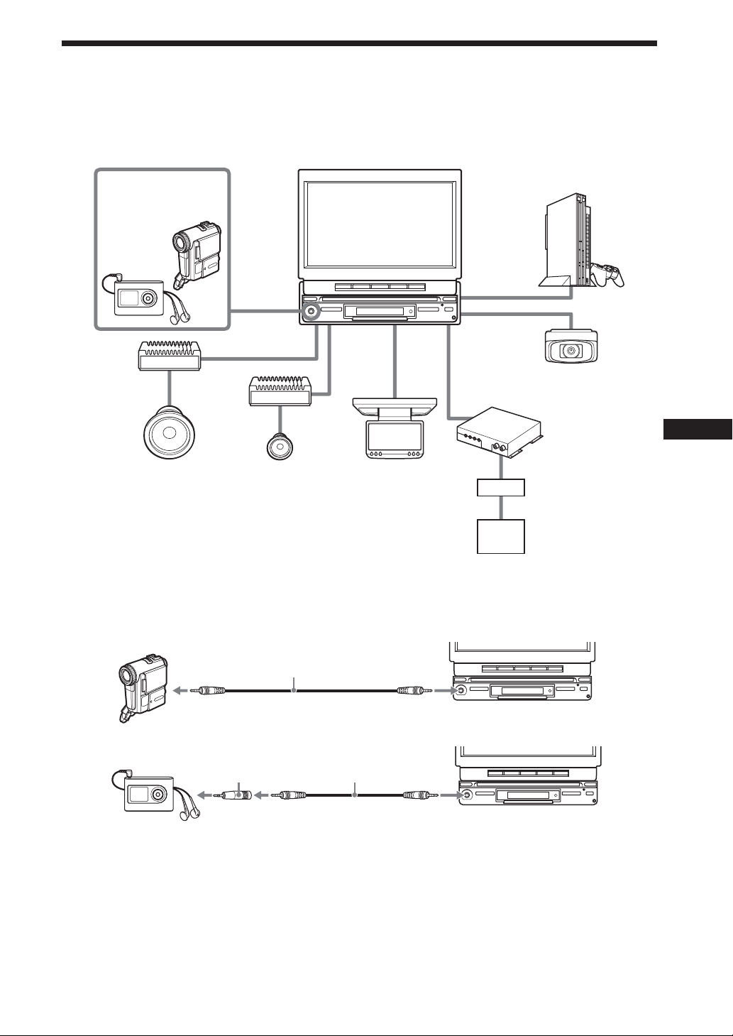
Connection Example
For details, see the section “1 Car Systems Connections” (pages 7 - 10). Be sure to refer also to the
documentation for all other components in the system.
System configuration
AV Center XAV-A1
Walkman or
Video Camera
(optional)
Game (optional)
A/V IN*
(Front)
(AUX 1)
Amplifier
(optional)
Amplifier
(optional)
Subwoofer
(optional)
* Connect with supplied connecting cable 3. (Use a conversion plug 4 when you connect the audio equipment.)
When you connect the video camera
Speaker
(optional)
SUB OUT
(MONO)
FRONT L/R
REAR L/R
Rear Monitor
(optional)
REAR
MONITOR
OUT
AUX 2
AUX 3
AUX 3 and BUS
Back Camera
(optional)
TV Tuner XT-V70
(optional)
Connection Box
XA-123
XM Radio Tuner
(optional)
3
When you connect the audio player
34
Notes
• Be sure to connect the ground cord before connecting the amplifier.
• If you connect an optional power amplifier and do not use the built-in amplifier, the beep sound will be deactivated.
5
Page 6
Connecting Information
For details, see the section “1 Car Systems Connections” (next page).
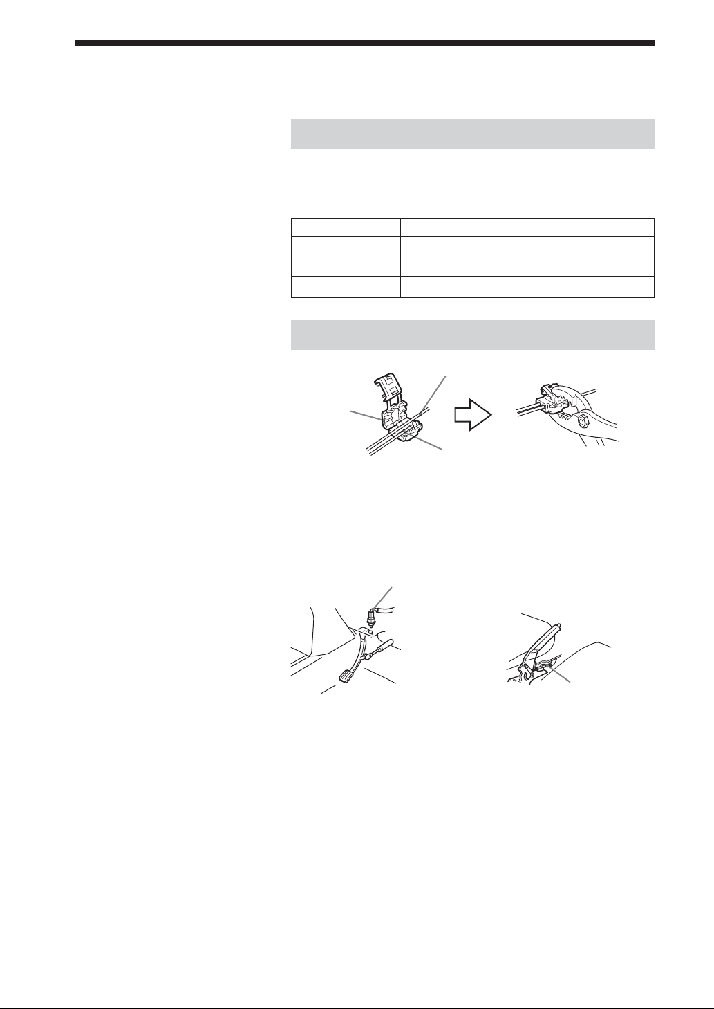
Connecting the cords
Notes
• Be sure to connect the power input
cord after all other cords are connected.
• If the parking brake switch cord is too
thin, connect the parking cord to the
parking brake switch cord directly
without using the tap.
Connect each cord using the taps. For the combination of each
cord, see the following table. Also, see the section “1 Car
Systems Connections” (next page).
Main unit side Car side
Orange/white Illumination signal cord
Purple/white Power terminal cord of the back lamp
Light green Parking brake switch cord
Using the tap
Parking brake switch cord
Tap 9
Parking cord
(Light green)
Connecting the parking cord
The mounting position of the parking brake switch cord depends
on your car. Refer to the system connection illustrations below
and consult your car dealer or your nearest Sony dealer for
further details.
Foot brake type Hand brake type
Parking brake
switch cord
Parking brake
switch cord
The cord for utilizing the back camera better
Purple/white cord (for the connection to the power terminal
cord of the back lamp)
If you connect the purple/white cord to the power terminal cord
of the back lamp, the image of back camera will be automatically
displayed on the monitor when a back lamp lights up. You can
adjust the parking location viewing the image of back camera
when you backup.
6
Page 7
1 Car Systems Connections
Refer also to the documentation for all other components in the system.
Also see “Connecting Information” on page 6.
• Components listed here except for supplied accessories are available separately. When connecting such
components, be sure to also refer to their documentation.
For specifications and other information on separately available components, contact your dealer.
Prevention of accidents caused by short-circuits
To prevent the risk of accidents caused by short-circuits, connect the power supply leads (red and yellow)
only after all other wiring has been completed, and only with the ignition key in the OFF position.
Otherwise, accidental short-circuiting can lead to electric shock and to serious damage.
When a fuse has blown, check the wiring and locate the cause of the problem before replacing the fuse.
When replacing the fuse, be sure to use only a fuse of the same rating (ampere rating). Using a different
fuse or bridging the contacts with wire is highly dangerous and can lead to serious damage.
Make sure to connect all of the following leads.
Otherwise there is a risk of electric shock, damage to the equipment, or malfunction.
• Connect purple/white lead to back lamp lead of car.
• Connect orange/white lead to illumination signal lead of car.
• Connect light green lead to parking brake switch lead of car.
• Connect yellow lead to battery power supply of car.
• Connect red lead to accessory power supply of car.
• Connect black lead to metal point on car chassis.
* Do not mix up the yellow and red leads, as this will cause the memory contents to be lost.
Observe the following precautions.
Otherwise there is a risk of electric shock, damage to the equipment, or malfunction.
• Cover unused connectors with electrician’s tape to prevent accidental contact.
• Route FM/AM antenna cable, bus cable, RCA interconnects, and power supply leads as far apart from
each other as possible, to prevent noise interference.
• Always grasp the connector and do not pull the cable when disconnecting the bus cable or other cables.
Otherwise the cable may become detached.
Notes on the control and power supply leads
• The power antenna control lead (blue) supplies +12 V DC when turn on the tuner.
• When your car has built-in FM / AM antenna in the rear / side glass, connect the power antenna
control lead (blue) or the accessory power input lead (red) to the power terminal of the existing
antenna booster. For details, consult your dealer.
•A power antenna without relay box cannot be used with this unit.
Memory hold connection
When the yellow power input lead is connected, power will always be supplied to the memory circuit
even when the ignition key is turned off.
7
Page 8

Notes on speaker connection
• Before connecting the speakers, turn the unit off.
• Use speakers with an impedance of 4 to 8 ohms, and with adequate power handling capacities to avoid
its damage.
• Do not connect the speaker terminals to the car chassis, or connect the terminals of the right speakers
with those of the left speaker.
• Do not connect the ground lead of this unit to the negative E terminal of the speaker.
• Do not attempt to connect the speakers in parallel.
• Connect only passive speakers. Connecting active speakers (with built-in amplifiers) to the speaker
terminals may damage the unit.
•To avoid a malfunction, do not use the built-in speaker wires installed in your car if the unit shares a
common negative E lead for the right and left speakers.
• Do not connect the unit’s speaker cords to each other.
8
Page 9
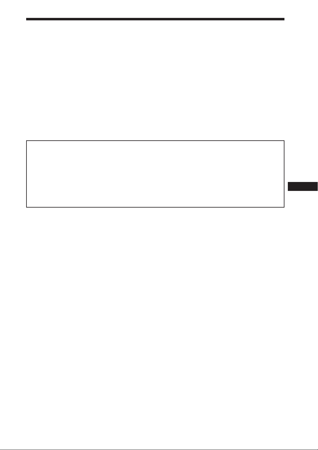
Connecting without optional TV tuner unit
RCA interconnects
Active subwoofer
(optional)
Rear speakers
(optional)
Amplifiers
(optional)
Front speakers
(optional)
Left
Front speakers
(optional)
Right
Left
Rear speakers
(optional)
Right
To a metal surface of the car
To the +12 V power terminal which is
energized at all times
*1
To the +12 V power terminal which is
energized in the accessory position of
the ignition key switch
*1*3
To a car’s illumination signal
To the + 12 V power terminal of the
back lamp lead of car
To AMP REMOTE IN of an optional
power amplifier
*4
To the power antenna control lead or
power supply lead of antenna booster
amplifier
*3*5
(optional)
SUB OUT (MONO)
RCA interconnects
(optional)
REAR L/R
RCA interconnects
(optional)
FRONT L/R
White
White/black
Gray
Gray/black
Green
Green/black
Purple
Purple/black
*2
*1
Protection device
Max. supply current 0.3 A
Max. supply current 0.3 A
To XM tuner (optional)
To the optional
back camera or a
video equipment
RC-104 (optional)
digital output
From car antenna
To game
etc.
To rear
monitor etc.
Black (0.35 m)
Yellow (0.35 m)
Red (0.25 m)
Orange/white (0.25 m)
Blue/white (0.25 m)
Blue (0.25 m)
Connection
box 1
AUX 3
AUX 2
REAR MONITOR OUT
Purple/White (5m)
Power
supply
leads 2
(for main
unit)
Fuse (10 A)
Parking brake switch lead of car
Tap 9
Light green (2.5 m)
*1 Be sure to connect the black ground lead to it first.
*2 First connect the black ground lead, then connect the yellow and red power input leads.
*3 When your car has built-in FM/AM antenna in the rear/side glass, see “Notes on the control and power
supply leads” (page 7).
*4 This connection is only for amplifiers. Connecting any other system may damage the unit.
*5 It is not necessary to connect this lead if there is no power antenna or antenna booster, or with a manually-
operated telescopic antenna.
Note on the accessory power input lead (red)
If there is no accessory position, connect to the +12 V power (battery) terminal which is energized at all times.
9
Page 10
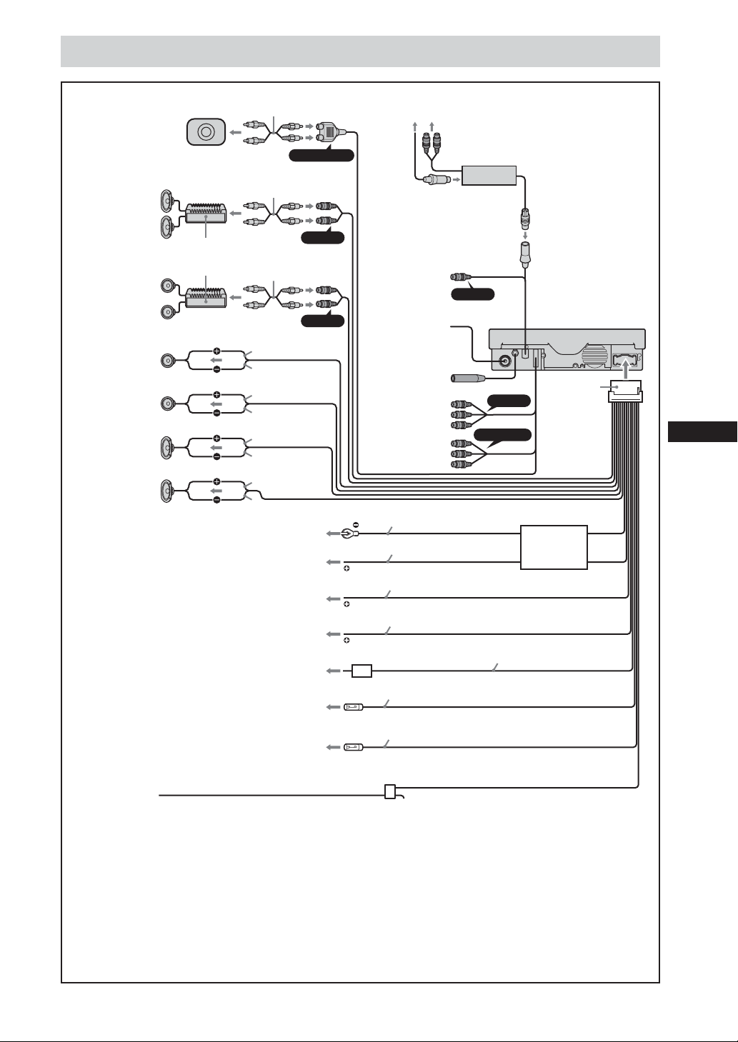
Connecting with optional TV tuner unit
Film antenna
Antenna cord
Tuner
amplifier
unit
To the optional back camera
or a video equipment
To the +12 V power
terminal which is
energized in the
accessory position of the
ignition key switch. Be
sure to connect the black
ground lead first.
To a metal point
of the car
Connection box 1
TV tuner unit
XT-V70
(optional)
AUX 3
To XM tuner (optional)
10
Page 11
2 Installing the Main Unit
Installation angle
The unit should be installed within an
angle of 30 degrees from horizontal. If
this angle is exceeded, the monitor may
not open up or retract properly.
Note
Keep the units and connection cables
apart.
After all connections are made, install the main unit to the
dashboard.
Before installation
This unit is designed to be completely safe, but if not installed
correctly, it can cause accidents. Be sure to verify the following
points before installation.
Install the main unit to the in-dash location, and the amplifier unit
under the navigator’s seat, etc.
• If the monitor in the opened position is close to a airconditioning outlet, the outlet should be closed.
• Install the unit so that the monitor when opened up will not
block access to the hazard switch or other important controls.
• Do not install the unit (monitor) in locations which may be
subject to excessively low or high temperatures. (Otherwise the
unit may be deformed and the LCD may be damaged.)
Exposure to direct sunlight can also lead to high temperatures
and should be avoided.
Selecting the installation location
Set the ignition key to OFF or remove it.
1
Place the units in their intended mounting
2
locations to check the cable length and monitor
installation conditions.
Installation procedure precautions
• Perform the installation carefully. Dropping the unit or
otherwise subjecting it to strong impact or force may deform
the chassis, resulting in failure of the monitor loading
mechanism or other defects.
NNTT
N T/N T/N T/NT
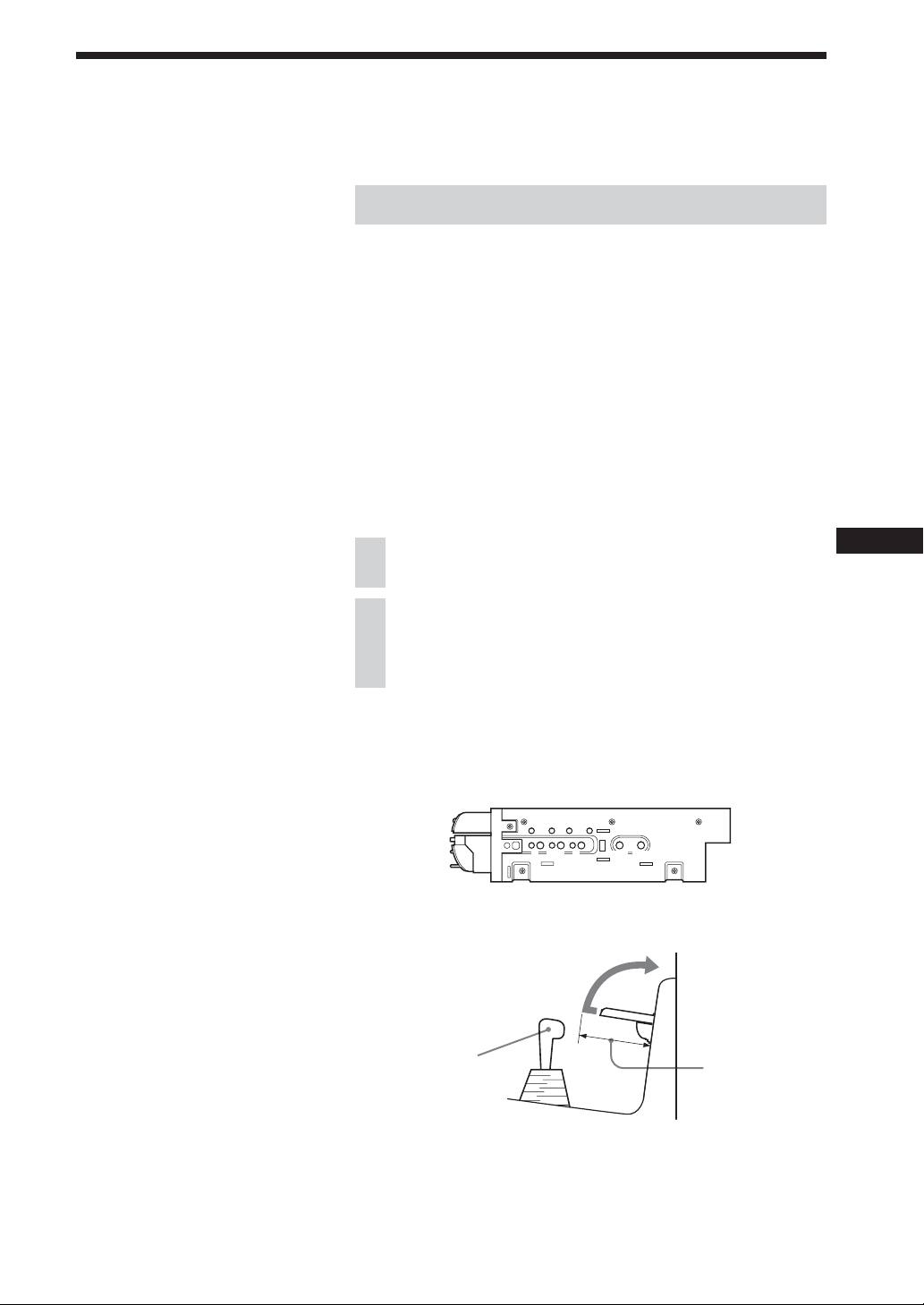
•To allow for proper opening and closing of the monitor, there
must be a clearance of at least 170 mm between the closest
position of the shift lever and the mounting surface for the unit.
Shift lever
• In some cases, the shift lever may touch the monitor when
moved to a certain position. Make sure that there is no
obstruction to driving operations.
• When installing this unit together with other car audio
equipment (single DIN slot size) in a stacked configuration,
install the main unit on top.
At least 170 mm
from mounting
surface
11
Page 12
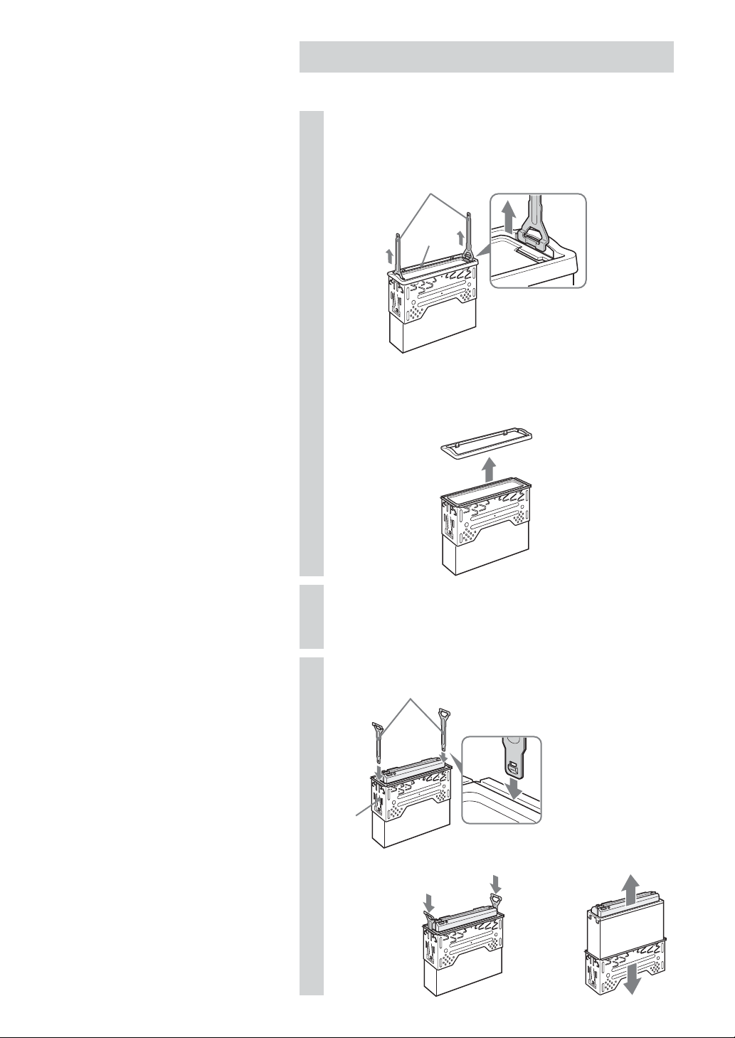
Removing the bracket
Before installing the unit, remove the bracket from the unit.
Remove the protection collar qa.
1
1 Enlarge the release keys qs together with the protection
collar qa.
qs
qa
Orient the release key qs correctly.
2 Pull out the release keys qs to remove the protection collar
qa.
12
Insert two release keys qs together into the unit
2
and the bracket 0 until they click.
Pull down the bracket 0, then pull up the unit to
3
separate.
0
qs
Face the hook
inwards.
m
,
Page 13
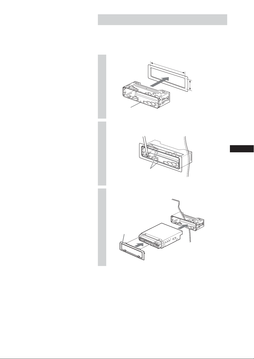
Installation procedure
Mounting example
When installing this unit, be sure to close the monitor of the unit.
If the monitor is opened while installing and given too much
force, it may cause a malfunction.
1
2
3
0
Claws
Dashboard
182
mm
53 m
m
qa
0
13
Page 14
Notes
• Do not press the front panel buttons of
the unit during installation and do not
apply strong force.
• Do not place any objects on top of the
unit.
• If a salient of the genuine bracket
touches the unit due to its figure, and
makes attachment hard, process the
bracket by scraping the salient off.
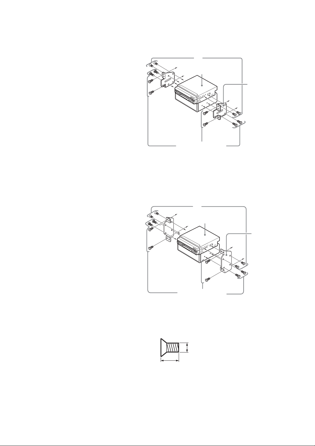
Toyota cars (illustration shows an example for a Toyota car)
Align the brackets of the factory-installed car stereo with the
mounting holes marked “T” on the side of the main unit, and use
the supplied screws to fasten the brackets. For Toyota cars, the
supplied screws 6 should be used.
6
XAV-A1
Bracket of
factory-installed
car stereo
Screws of factoryinstalled car stereo
bracket
Nissan cars
Align the brackets of the factory-installed car stereo with the
mounting holes marked “N” on the side of the main unit, and use
the supplied pan-head screws 6 to fasten the brackets.
6
XAV-A1
Bracket of
factory-installed
car stereo
Screws of factoryinstalled car stereo
bracket
* Be sure to use only the supplied pan-head screws 6 for
installation. If any other screws are used, make sure they
conform to the requirements shown below.
Using longer screws can cause internal damage to the unit.
5 mm
6 mm
Damage can also occur if the screws are used directly on the
unit without the brackets of the factory-installed car stereo.
14
Page 15

3 After Installation and Connections
Start the car’s engine.
1
Verify that the brake lights, other lights, horn, turn
2
indicators, and all other electrical parts operate
normally.
Note
To avoid the possibility of damage, you
should not use a needle or push the
button too strongly.
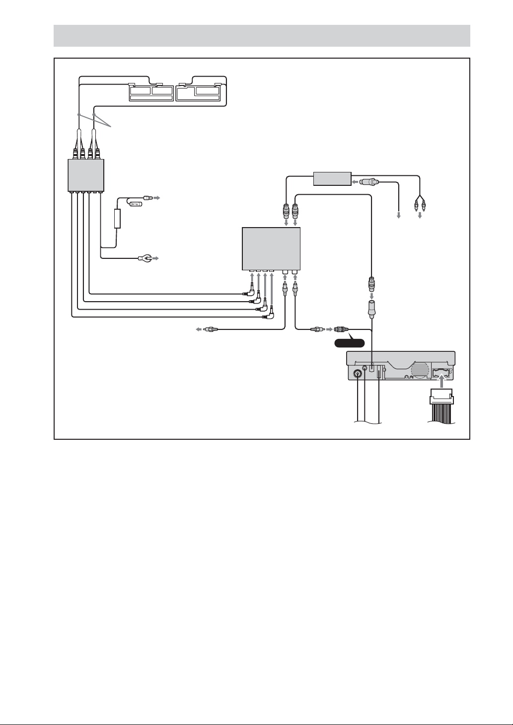
Use a mechanical-pencil or similar to push the Reset
3
button on the unit.
Reset button
When you press the Reset button, the system becomes
operative.
15
Page 16

Précautions
Cet appareil est conçu uniquement
pour les systèmes 12 V CC à masse
négative
L’appareil n’est pas utilisable sur les camions ou
autres voitures à système 24 V. Cela pourrait
entraîner un risque d’incendie et de dommages.
Remarques concernant le cordon
d’alimentation (jaune)
• Au raccordement de l’appareil en combinaison
avec d’autres composants stéréo, la valeur
nominale du circuit de la voiture connecté doit
être supérieure à la somme des fusibles de
chaque composant.
• Si aucun circuit de la voiture n’a de valeur
nominale suffisamment élevée, connectez
l’appareil directement à la batterie.
Ne désassemblez pas et ne trafiquez
pas l’appareil
Cela pourrait provoquer une décharge électrique,
des blessures ou un incendie. Ne connectez pas
directement le cordon d’alimentation d’un autre
système à celui de cet appareil. Si vous avez des
doutes sur la sécurité de l’installation de cet
appareil, consultez le revendeur Sony le plus
proche.
N’installez pas cet appareil à un
emplacement gênant le
fonctionnement de l’airbag
Cela pourrait constituer un risque d’accident ou
de blessures.
Utilisez uniquement le fusible spécifié
Au remplacement du fusible, utilisez uniquement
un fusible ayant la même valeur nominale
(ampérage). Sinon, un risque d’incendie est
possible.
Attention
•Prenez garde que les fils ne soient pas coincés
sous une vis, ou happés par des pièces mobiles
(par ex. rails de sièges).
•Avant d’effectuer les raccordements, coupez la
clé de contact de la voiture pour éviter les
courts-circuits.
• Connectez les conducteurs d’entrée
d’alimentation jaune et rouge seulement une
fois que tous les autres conducteurs sont
raccordés.
• Acheminez tous les fils de mise à la masse à
un point de mise à la masse commun.
• Par mesure de sécurité, isolez bien tous les fils
non-connectés desserrés avec du chatterton.
Sécurité
Conformez-vous à la réglementation de la
circulation de votre pays.
2
Page 17

Table des matières
Précautions...................................................................................................... 2
Liste des pièces ............................................................................................... 4
Exemple de raccordements ............................................................................ 5
Informations sur les raccordements .............................................................. 6
Raccordement des cordons............................................................................................... 6
Emploi du branchement ................................................................................................... 6
1 Raccordement des systèmes de la voiture .............................................. 7
Raccordement sans syntoniseur TV en option .............................................................. 9
Raccordement avec un syntoniseur TV en option ...................................................... 10
2 Installation de l’appareil ......................................................................... 11
Avant l’installation ........................................................................................................... 11
Retrait de l’étrier .............................................................................................................. 12
Procédure d’installation .................................................................................................. 13
3 Après l’installation et les raccordements .............................................. 15
3
Page 18

Liste des pièces
Les numéros de la liste correspondent à ceux dans le manuel.
123
456
×4
789
×4
q; qa qs
ATTENTION
Manipulez le support
0 avec soin pour ne
pas vous blesser aux
doigts.
×4
×2
4
Page 19

Exemple de raccordements
Pour les détails, consultez la section « 1 Raccordements des systèmes de la voiture » (pages 7-10).
Consultez aussi la documentation pour tous les autres composants du système.
Configuration du système
Centre AV XAV-A1
Walkman ou
vidéocaméra
(en option)
A/V-IN*
(avant)
(AUX 1)
AUX 2
Jeu (en option)
SUB OUT
Amplificateur
(en option)
Amplificateur
(en option)
Haut-parleur
d’extrême grave
(en option)
* Connectez avec le câble de raccordement fourni 3. (Utilisez une fiche de conversion 4 si vous connectez un
équipement audio.)
Quand vous raccordez une vidéocaméra
(MONO)
Haut-parleur
(en option)
FRONT L/R
REAT L/R
Moniteur arrière
(en option)
REAR
MONITOR
OUT
AUX 3
AUX 3 et
BUS
Caméra arrière
(en option)
Syntoniseur TV
XT-V70 (en option)
Boîte de raccordement
XA-123
Syntoniseur radio
XM (en option)
3
Quand vous raccordez un lecteur audio
34
Remarques
• Raccordez bien le fil de mise à la masse avant de connecter l’amplificateur.
• Si vous raccordez un amplificateur de puissance en option et n’utilisez pas l’amplificateur intégré, la tonalité bip
sera désactivée.
5
Page 20

Informations sur les raccordements
Pour les détails, consultez la section « 1 Raccordement des systèmes de la voiture » (page suivante).
Raccordement des cordons
Remarques
• Connectez bien le cordon
d’alimentation après le raccordement
de tous les autres cordons.
• Si le cordon du commutateur du frein
de stationnement est trop fin, raccordez
directement le cordon de
stationnement au cordon du
commutateur du frein de
stationnement sans utiliser le
branchement.
Raccordez chaque cordon en utilisant les branchements. Voir le
tableau ci-dessous pour la combinaison pour chaque cordon.
Consultez également la section « 1 Raccordement des systèmes
de la voiture » (page suivante).
Côté appareil Côté voiture
Orange/blanc Cordon de signal d’éclairage
Violet/blanc Cordon de terminal d’alimentation du feu arrière
Vert clair Cordon de commutation du frein de stationnement
Emploi du branchement
Cordon du commutateur de frein de
stationnement
Branchement
9
Cordon de frein de
stationnement (vert clair)
Raccordement du cordon de frein de
stationnement
La position de montage du cordon du commutateur de frein de
stationnement dépend de la voiture. Rapportez-vous aux
illustrations de connexion du système ci-dessous et consultez
votre revendeur auto ou le revendeur Sony le plus proche pour
les détails.
Type frein au pied Type frein à main
Cordon du commutateur de
frein de stationnement
Cordon du commutateur
de frein de stationnement
Cordon permettant de mieux utiliser la caméra
arrière
Cordon violet/blanc (pour la connexion au cordon de borne
d’alimentation du feu arrière)
Si vous connectez le cordon violet/blanc au cordon de borne
d’alimentation du feu arrière, l’image de la caméra arrière sera
automatiquement affichée au moniteur quand le feu arrière
s’allumera. Vous pouvez ajuster l’emplacement de parking en
regardant l’image de la caméra arrière en reculant.
6
Page 21

1 Raccordement des systèmes de la voiture
Consultez également la documentation pour tous les autres composants du
système.
Également voir « Informations sur les raccordements » à la page 6.
• Les composants énumérés ici, sauf les accessoires fournis, sont disponibles séparément. Au
raccordement de tels composants, consultez leur documentation.
Pour les spécifications et autres informations sur les composants disponibles séparément, contactez
votre revendeur.
Prévention des accidents causés par court-circuit
Pour éviter les risques d’accident dus à des courts-circuits, connectez les conducteurs d’alimentation
(rouge et jaune) seulement une fois que le reste du câblage a été terminé, et seulement avec la clé de
contact en position OFF.
Sinon, un court-circuitage accidentel pourrait provoquer une décharge électrique et de sérieux
dommages.
Quand un fusible a sauté, vérifiez le câblage et localisez la cause du problème avant de remplacer le
fusible.
Au remplacement du fusible, utilisez uniquement un fusible de valeur nominale (ampérage) identique.
L’emploi d’un fusible différent ou le shuntage des contacts avec un fil est très dangereux et peut causer
de sérieux dommages.
Vérifiez que tous les conducteurs suivants sont connectés.
Sinon il y a un risque de décharge électrique, de dommage à l’équipement et de dysfonctionnement.
• Connectez le conducteur violet/blanc au conducteur du feu arrière de la voiture.
• Connectez le conducteur orange/blanc au conducteur de signal d’illumination de la voiture.
• Connectez le conducteur vert clair au conducteur du commutateur de frein de stationnement de la
voiture.
• Connectez le conducteur jaune à l’alimentation de la batterie de la voiture.
• Connectez le conducteur rouge à l’alimentation accessoire de la voiture.
• Connectez le conducteur noir à une surface métallique sur le châssis de la voiture.
* Ne mélangez pas les conducteurs jaune et rouge, cela provoquerait la perte des contenus de la
mémoire.
Observez les précautions suivantes.
Un risque de décharge électrique, de dommages pour l’équipement ou de dysfonctionnement est
possible.
• Couvrez les connecteurs inutilisés de charterton pour éviter tout contact accidentel.
• Acheminez le câble d’antenne FM/AM, le câble de bus, les interconnexions RCA, et les conducteurs
d’alimentation aussi écartés les uns des autres que possible pour éviter les bruits parasites.
• Saisissez toujours le connecteur, ne tirez pas sur le câble lui-même lors de la déconnexion du câble de
bus ou d’autres câbles. Sinon le câble pourrait se détacher.
Remarques sur les conducteurs de commande et d’alimentation
• Le conducteur de commande de l’antenne motorisée (bleu) fournit +12 V CC quand le syntoniseur est
activé.
• Si votre voiture a une antenne FM/AM intégrée à la vitre arrière/move latérale, connectez le
conducteur de commande de l’antenne motorisée (bleu) ou le conducteur d’entrée d’alimentation
accessoire (rouge) à la borne d’alimentation de l’amplificateur d’antenne existant. Pour les détails,
consultez votre revendeur.
• Une antenne motorisée sans boîte de relais est inutilisable avec cet appareil.
Connexion de maintien de la mémoire
Quand le conducteur d’entrée d’alimentation jaune est connecté, le circuit de mémoire est toujours
alimenté, même quand la clé de contact est coupée.
7
Page 22

Remarques sur la connexion des enceintes
• Mettez l’appareil hors tension avant de raccorder les enceintes.
• Utilisez des enceintes à impédance de 4 à 8 ohms, et à capacités de traitement de la puissance adaptées
pour éviter les dommages.
• Ne connectez pas les bornes des enceintes au châssis de la voiture, ou les bornes de l’enceinte droite à
celles de l’enceinte gauche.
• Ne connectez pas le fil de mise à la masse de cet appareil à la borne négative E d’une enceinte.
• N’essayez pas de connecter les enceintes en parallèle.
• Connectez seulement des enceintes passives. La connexion d’enceintes actives (avec amplificateur
intégré) aux bornes d’enceinte peut endommager l’appareil.
• Pour éviter un dysfonctionnement, n’utilisez pas les fils du haut-parleur intégré installé dans votre
voiture si l’appareil partage un conducteur négatif E commun pour les enceintes droite et gauche.
• Ne connectez pas les cordons d’enceinte de l’appareil l’un à l’autre.
8
Page 23

Raccordement sans syntoniseur TV en option
Interconnexions
Haut-parleur
RCA (en option)
d’extrême grave
actif (en option)
SUB OUT (MONO)
Interconnexions
RCA (en option)
Enceintes
arrière (en
option)
Amplificateurs
(en option)
Interconnexions
RCA (en option)
REAR L/R
Enceintes
avant (en
option)
Gauche
Enceintes avant
(en option)
Droite
Gauche
Enceintes arrière
Vert
Vert/noir
FRONT L/R
Blanc
Blanc/noir
Gris
Gris/noir
(en option)
Droite
Violet
Violet/noir
A une surface métallique de la voiture
A la borne d’alimentation +12 V
toujours excitée
*1
*2
A la borne d’alimentation +12 V
excitée en position accessoire du
commutateur de clé de contact
Au signal d’éclairage de la voiture
*1*3
*1
A la borne d’alimentation +12 V du
conducteur de feu arrière de la voiture
A AMP REMOTE IN d’un amplificateur
de puissance en option
*4
Courant d’alimentation max. 0,3 A
Au conducteur de commande d’antenne
motorisée ou au conducteur
d’alimentation d’un amplificateur
d’antenne
*3*5
Courant d’alimentation max. 0,3 A
Conducteur de commutateur de frein
de stationnement de la voiture
*1 Connectez bien le fil de mise à la masse noir en premier.
*2 Connectez d’abord le fil de mise à la masse noir, puis les conducteurs d’entrée d’alimentation jaune et rouge.
*3 Si votre voiture a une antenne FM/AM intégrée à la vitre arrière/move latérale, consultez « Remarques sur
les conducteurs de commande et d’alimentation » (page 7).
*4 Cette connexion est seulement pour les amplificateurs. La connexion d’un autre système peut endommager
l’appareil.
*5 La connexion de ce conducteur est inutile s’il n’y a pas d’antenne motorisée ou d’amplificateur d’antenne, ou
avec une antenne télescopique opérée manuellement.
Remarque sur le conducteur d’entrée d’alimentation accessoire (rouge)
S’il n’y a pas de position accessoire, connectez-le à la borne +12 V (batterie) qui est toujours excitée.
Au syntoniseur XM (en option)
Boîte de
raccordement
1
A une caméra
arrière ou un
équipement
vedéo en option
Sortie
numérique RC104 (en option)
De l’antenne
de la voiture
A jeu etc.
Au moniteur
arrière etc.
Noir (0,35 m)
Jaune (0,35 m)
Rouge (0,25 m)
Orange/blanc (0,25 m)
Dispositif de
protection
Bleu/blanc (0,25 m)
Bleu (0,25 m)
Vert clair (2,5 m)
Branchement 9
AUX 3
AUX 2
Conducteurs
REAR MONITOR OUT
d’alimentation
2
l’appareil)
Fusible
(10 A)
Violet/blanc (5 m)
(pour
9
Page 24

Raccordement avec un syntoniseur TV en option
Antenne film
Cordon d'antenne
Amplificateur
syntoniseur
A une caméra arrière ou
un équipement
vidéo en option
A la borne d'alimentation
+12 V excitée en position
accessoire de la clé de
contact. Connectez bien
le conducteur de terre
noire en premier.
A une surface
métallique de la
voiture
Boîte de raccordement 1
Syntoniseur
TV XT-V70
(en option)
AUX 3
Au syntoniseur XM
(en option)
10
Page 25

2 Installation de l’appareil
Angle d’installation
L’appareil doit être installé à un angle de
moins de 30˚ de l’horizontale. Si cet angle
est dépassé, le moniteur peut ne pas
s’ouvrir ou se rétracter correctement.
Remarque
Maintenez les composants et câbles de
raccordement séparés.
Une fois tous les raccordements effectués, installez l’appareil sur
le tableau de bord.
Avant l’installation
Cet appareil est conçu pour être entièrement sûr, mais il peut
causer des accidents s’il n’est pas installé correctement. Vérifiez
les points suivants avant l’installation.
Installez l’appareil dans le tableau de bord, et l’amplificateur sous
le siège du navigateur etc.
• Si le moniteur en position sortie est proche d’une sortie d’air de
climatiseur, elle doit être fermée.
• Installez l’appareil de sorte que le moniteur en position sortie
ne bloque pas l’accès au commutateur de signal de détresse ou
à d’autres commandes importantes.
• N’installez pas l’appareil (moniteur) à un emplacement soumis
à des températures trop basses ou élevées. (Sinon il pourrait
être déformé et l’écran ACL endommagé.)
L’exposition en plein soleil qui peut aussi entraîner des
températures élevées doit être évité.
Sélection de l’emplacement d’installation
Mettez la clé de contact sur OFF ou retirez-la.
1
Placez les composants aux emplacements de
2
montage prévus pour vérifier la longueur des
câbles et l’état d’installation du moniteur.
Précautions pour l’installation
•Effectuez l’installation soigneusement. La chute de l’appareil ou
sa soumission à un impact violent ou une force peut
endommager le boîtier, ce qui peut entraîner une défaillance du
mécanisme de charge du moniteur ou d’autres défauts.
NNTT
N T/N T/N T/NT
• Pour permettre la sortie et la rentrée du moniteur, il doit y avoir
un jeu d’au moins 170 mm entre la position la plus proche du
levier de vitesses et la surface de montage de l’appareil.
Levier de
vitesses
• Dans certains cas, le levier de vitesses peut toucher le moniteur
quand il est déplacé à une certaine position. Vérifiez qu’il n’y a
pas obstruction aux opérations de conduite.
•À l’installation de l’appareil avec un autre autoradio (format un
logement DIN) en configuration empilée, installez l’appareil
dessus.
Au moins 170
mm de la surface
de montage
11
Page 26

Retrait de l’étrier
Avant d’installer l’appareil, retirez l’étrier.
Retirez le collier de protection qa.
1
1 Élargissez les clés de libération qs ensemble avec le collier
de protection qa.
qs
qa
Orientez correctement la clé de libération qs.
2 Retirez les clés de libération qs pour retirer le collier de
protection qa.
12
Insérez les deux clés de libération qs ensemble
2
dans l’appareil et l’étrier q; jusqu’au déclic.
Poussez l’étrier q; vers le bas, puis tirez l’appareil
3
pour le séparer.
qs
Placez le crochet
vers l’intérieur.
q;
m
,
Page 27

Procédure d’installation
Exemple de montage
À l’installation de cet appareil, rentrez bien le moniteur.
Si le moniteur est sorti pendant l’installation et qu’une force
excessive est exercée dessus, un dysfonctionnement peut en
résulter.
182
1
q;
mm
53 m
m
2
3
Ergots
Tableau de bord
q;
qa
13
Page 28

Remarques
• N’appuyez pas sur les touches du
panneau avant de l’appareil pendant
l’installation et n’exercez pas une force
excessive dessus.
• Ne placez pas d’objet sur l’appareil.
• Si une saillie de l’étrier d’origine
touche l’appareil à cause de sa forme et
rend la fixation difficile, traitez l’étrier
en grattant la saillie.
Voitures Toyota (l’illustration montre l’exemple d’une voiture
Toyota)
Alignez les étriers de l’autoradio installé à l’usine sur les trous de
montage marqués « T » sur le côté de l’appareil, et utilisez les vis
fournies pour fixer les étriers. Pour une voiture Toyota, utilisez les
vis fournies 6.
6
XAV-A1
Étrier de
l’autoradio
installé à l’usine
Vis de l’étrier de
l’autoradio installé
à l’usine
Voitures Nissan
Alignez les étriers de l’autoradio installé à l’usine sur les trous de
montage marqués « N » sur le côté de l’appareil, et utilisez les vis
à tête plate 6 fournies pour fixer les étriers.
6
XAV-A1
Étrier de
l’autoradio
installé à l’usine
Vis de l’étrier de
l’autoradio installé
à l’usine
* Utilisez bien les vis à tête plate 6 fournies pour l’installation. Si
d’autres vis sont utilisées, vérifiez qu’elles sont conformes aux
exigences ci-dessous.
L’emploi de vis plus longues peut provoquer des dommages
internes à l’appareil.
5 mm
6 mm
Des dommages peuvent survenir si les vis sont utilisées
directement sur l’appareil sans les étriers de l’autoradio installé
à l’usine.
14
Page 29

3 Après l’installation et les raccordements
Démarrez le moteur de la voiture.
1
Vérifiez que les feux de frein, autres feux, le
2
klaxon, les clignotants et toutes les autres pièces
électriques fonctionnent normalement.
Remarque
Pour éviter toute possibilité de
dommages, n’utilisez pas d’aiguille et
n’appuyez pas trop fort sur le bouton.
Utilisez un stylomine ou similaire pour appuyer sur
3
le bouton de réinitialisation sur l’appareil.
Bouton de réinitialisation
À la pression du bouton de réinitialisation, le système
devient opérationnel.
15
Page 30

Precauciones
La unidad se diseñó sólo para sistemas
con CC de 12V con tierra negativa
Esta unidad no puede utilizarse en camiones u
otros coches con sistemas de 24V. Puede provocar
un incendio y daños.
No desarme o haga cambios en la
unidad
Puede provocar una descarga eléctrica, heridas
personales o incendio. No conecte un cable
eléctrico de otro sistema directamente al cable
eléctrico de esta unidad. Si tiene dudas acerca de
la instalación segura de esta unidad, consulte con
su tienda de Sony más cercana.
No instale en lugares donde interfiera
con el funcionamiento de la bolsa de
aire
Puede provocar un accidente y heridas.
Utilice sólo el fusible especificado
Cuando cambie el fusible, asegúrese de utilizar
sólo un fusible del mismo nivel (amperaje). De lo
contrario existe el peligro de un incendio.
Precauciones
• No apriete cables debajo de un tornillo o
atrapados por piezas móviles (por ejemplo rieles
del asiento).
• Antes de hacer las conexiones, gire la llave de
encendido del coche a OFF para evitar
cortocircuitos.
• Conecte los cables de entrada eléctrica amarillo
y rojo sólo después de conectar los otros cables.
• Pase todos los cables a tierra a un punto de
tierra común.
• Asegúrese de aislar todos los cables flojos sin
conexión con cinta de aislación para su
seguridad.
Notas acerca del cable eléctrico (amarillo)
• Cuando conecte esta unidad en combinación con
otros componentes estéreo, el régimen del
circuito del coche conectado debe ser mayor que
la suma de fusibles de cada componente.
• Cuando no hay circuitos de coche que tengan un
régimen suficientemente alto, conecte la unidad
directamente a la batería.
Acerca de la seguridad
Respete las leyes del tránsito en su país.
2
Page 31

Índice
Precauciones ................................................................................................... 2
Lista de piezas................................................................................................. 4
Ejemplo de conexión ...................................................................................... 5
Información de conexiones............................................................................ 6
Conexión de cables ............................................................................................................ 6
Uso de la bifurcación ......................................................................................................... 6
1 Conexiones de sistemas del coche ........................................................... 7
Conexión sin unidad de sintonizador de TV opcional................................................. 9
Conexión con la unidad de sintonizador de TV opcional ......................................... 10
2 nstalación de la unidad principal ........................................................... 11
Antes de la instalación .................................................................................................... 11
Desmontaje de la ménsula .............................................................................................. 12
Procedimiento de instalación ......................................................................................... 13
3 Después de la instalación y conexiones ................................................ 15
3
Page 32

Lista de piezas
Los números en la lista corresponden a los que aparecen en las instrucciones.
123
456
×4
789
×4
q; qa qs
PRECAUCIÓN
Manipule
cuidadosamente la
ménsula 0 para no
herir sus dedos.
×4
×2
4
Page 33

Ejemplo de conexión
Para más detalles, vea la sección “1 Conexiones de sistemas del coche” (páginas 7 - 10). Asegúrese de
consultar también la documentación para los otros componentes del sistema.
Configuración del sistema
Centro AV XAV-A1
Walkman o
videocámara
(opcional)
A/V IN*
(adelante)
(AUX 1)
AUX 2
Juego (opcional)
SUB OUT
Amplificador
(opcional)
Amplificador
(opcional)
Altavoz de
subgraves
(opcional)
* Conecte con el cable de conexión 3 entregado. (Utilice un enchufe de conversión 4 cuando conecte el equipo de
audio.)
Cuando conecte la videocámara
Altavoz
(opcional)
(MONO)
FRONT
L/R
REAR
L/R
Monitor trasero
(opcional)
REAR
MONITOR
OUT
AUX 3
AUX3 y BUS
Cámara trasera
(opcional)
Sintonizador de TV
XT-V70 (opcional)
Caja de conexiones
XA-123
Sintonizador de
radio XM (opcional)
3
Cuando conecte el reproductor de audio
34
Notas
• Asegúrese de conectar el cable de conexión a tierra antes de conectar el amplificador.
• Si conecta un amplificador de potencia opcional y no utiliza el amplificador integrado, se desactivará el sonido de
timbre.
5
Page 34

Información de conexiones
Para más detalles, consulte la sección “1 Conexiones de sistemas del coche” (siguiente página).
Conexión de cables
Notas
• Asegúrese de conectar el cable de
entrada eléctrico después de haber
conectado todos los demás cables.
• Si el cable del interruptor del freno de
estacionamiento es demasiado fino,
conecte directamente el cable de
estacionamiento en el cable del
interruptor del freno de
estacionamiento sin utilizar la
bifurcación.
Conecte cada cable utilizando las bifurcaciones. Para la
combinación de cada cable, consulte el siguiente cuadro. Vea
también la sección “1 Conexiones de sistemas del coche”
(siguiente página).
Lado de la unidad principal
Naranja/blanco
Púrpura/blanco
Verde claro
Lado del coche
Cable de señal de iluminación
Cable de terminal eléctrico de la luz
de marcha atrás
Cable del interruptor del freno de
estacionamiento
Uso de la bifurcación
Cable de interruptor del freno
de estacionamiento
Bifurcación
9
Cable de estacionamiento
(verde claro)
Conexión del cable de estacionamiento
La posición de montaje del cable del interruptor del freno de
estacionamiento depende de su coche. Consulte las figuras de
conexión del sistema abajo y consulte con el concesionario de su
coche o su tienda de Sony más cercana para más detalles.
Tipo freno de piso Tipo freno de mano
Cable de interruptor
del freno de
estacionamiento
Cable del interruptor
del freno de
estacionamiento
El cable para utilizar mejor la cámera trasera
Cable púrpura/blanco (para la conexión al cable de terminal
eléctrico de la luz de marcha atrás)
Si conecta el cable púrpura/blanco al cable de terminal eléctrico
en la luz de marcha atrás, la imagen de la cámara trasera
aparecerá automáticamente en el monitor cuando se enciende la
luz de marcha atrás. Puede ajustar la visión de la imagen del
lugar de estacionamiento en su cámara trasera cuando dé marcha
atrás.
6
Page 35

1 Conexiones de sistemas del coche
Consulte también la documentación para todos los demás componentes del
sistema.
También vea la “Información de conexiones” en la página 6.
• Los componentes en esta lista, excepto los accesorios entregados se pueden comprar por separado.
Cuando se conectan estos componentes, asegúrese de consultar también su respectiva documentación.
Para especificaciones y otra información de componentes en venta por separado, hable con su tienda.
Prevención de accidentes por cortocircuito
Para evitar el riesgo de accidentes provocado por cortocircuitos, conecte los cables de alimentación
eléctrica (rojo y amarillo) sólo después de haber terminado todos los demás cableados y sólo con la llave
de encendido en la posición OFF.
De lo contrario, un cortocircuito accidental puede provocar una descarga eléctrica y un daño grave.
Cuando se quemó un fusible, verifique el cableado y busque la causa del problema antes de cambiar el
fusible.
Cuando cambie un fusible, asegúrese de utilizar sólo un fusible del mismo régimen (régimen de
amperaje). El uso de un fusible diferente o la creación de un puente entre los contactos con un alambre es
muy peligroso y puede provocar daños graves.
Asegúrese de conectar todos los siguientes cables.
De lo contrario existe el riesgo de una descarga eléctrica, daño del equipo o mal funcionamiento.
• Conecte el cable púrpura/blanco al cable de la luz de marcha atrás del coche.
• Conecte el cable naranja/blanco al cable de señal de iluminación del coche.
• Conecte el cable verde claro en el cable del interruptor de freno de estacionamiento del coche.
• Conecte el cable amarillo en la alimentación eléctrica de la batería del coche.
• Conecte el cable rojo en la alimentación eléctrica de accesorios del coche.
• Conecte el cable negro en el punto de metal del chasis del coche.
* No mezcle los cables amarillo y rojo ya que puede perder el contenido de la memoria.
Respete las siguientes precauciones.
De lo contrario existe el riesgo de una descarga eléctrica, daño al equipo o mal funcionamiento.
• Cubra los conectores no utilizados con cinta de electricista para evitar un contacto por accidente.
• Pase el cable de antena FM/AM, cable colector, interconexiones RCA y cables de alimentación eléctrica
lo más lejos que sea posible entre sí para evitar ruidos de interferencia.
•Tome siempre por los conectores y no tire del cable para desconectar el cable colector u otros cables. De
lo contrario el cable puede desengancharse.
Notas acerca de los cables de control y alimentación eléctrica
• El cable de control de antena eléctrica (azul) alimenta una CC de +12 V cuando encienda el
sintonizador.
• Cuando su coche tiene una antena de FM/AM integrada en el vidrio trasero/lateral, conecte el cable
de control de antena eléctrica (azul) o el cable de entrada eléctrica de accesorios (rojo) en el terminal
eléctrico del reforzador de antena existente. Para más detalles, consulte con su tienda.
• No puede utilizar una antena eléctrica sin caja de relés con esta unidad.
Conexión de retención de memoria
Cuando se conecta el cable de entrada eléctrica amarillo, pasará siempre electricidad al circuito de
memoria incluso cuando gire la llave de encendido a OFF.
7
Page 36

Notas acerca de la conexión de altavoces
• Antes de conectar los altavoces, apague la unidad.
• Utilice altavoces con una impedancia de 4 a 8 ohmios y con suficiente capacidad de aceptación eléctrica
para evitar que se dañen.
• No conecte los terminales de altavoz en el chasis del coche o conecte los terminales del altavoz derecho
con los del altavoz izquierdo.
• No conecte el cable a tierra de esta unidad en el terminal negativo E del altavoz.
• No trate de conectar altavoces en paralelo.
• Conecte sólo altavoces pasivos. La conexión de altavoces activos (con amplificadores integrados) en los
terminales de altavoz puede dañar la unidad.
• Para evitar un mal funcionamiento, no utilice los cables de altavoces integrados instalados en su coche
si la unidad comparte un cable negativo E común para los altavoces derecho e izquierdo.
• No conecte los cables de altavoces de la unidad entre sí.
8
Page 37

Conexión sin unidad de sintonizador de TV opcional
Interconexiones
Altavoz de
subgraves activo
(opcional)
Altavoces
traseros
(opcional)
Amplificadores
(opcional)
Altavoces
delanteros
(opcional)
izquierdo
Altavoces delanteros
(opcional)
Derecho
izquierdo
Altavoces traseros
(opcional)
Derecho
A una superficie de metal del coche
Al terminal eléctrico de +12 V que recibe
electricidad todo el tiempo
Al terminal eléctrico de +12 V que recibe
electricidad en la posición de accesorios
del interruptor de la llave de
encendido
*1*3
A la señal de iluminación del coche
Al terminal eléctrico de +12 V del cable
de la luz de marcha atrás del coche
Al AMP REMOTE IN de un
amplificador de potencia opcional
Al cable de control de antena eléctrica
o cable de alimentación eléctrica del
amplificador reforzador de antena
RCA (opcional)
SUB OUT (MONO)
Interconexiones
RCA (opcional)
REAR L/R
Interconexiones
RCA (opcional)
FRONT L/R
Blanco
Blanco/negro
Gris
Gris/negro
Verde
Verde/negro
Púrpura
Púrpura/negro
*2
*1
*1
Equipo de protección
*4
*3*5
Al sintonizador XM (opcional)
Caja de conexiones 1
A la cámara
trasera o
un equipo de
video opcional
AUX 3
Salida digital
RC-104
(opcional)
De la antena
de coche
Al juego,
AUX 2
etc.
Al monitor
REAR MONITOR OUT
trasero, etc.
Negro (0,35 m)
Amarillo (0,35 m)
Rojo (0,25 m)
Naranja/blanco (0,25 m)
Púrpura/blanco (5 m)
Azul/blanco (0,25 m)
Máx. alimentación de corriente 0,3 A
Azul (0,25 m)
Máx. alimentación de corriente 0,3 A
Cable de
alimentación
eléctrica
2
(para la
unidad
principal)
Fusible
(10 A)
Cable del interruptor de freno de
estacionamiento del coche
Verde claro (2,5 m)
Bifurcación 9
*1 Asegúrese de conectar primero el cable a tierra negro.
*2 Conecte primero el cable a tierra negro y después conecte los cables de entrada eléctrica amarillo y rojo.
*3 Cuando su coche tiene una antena FM/AM integrada en el vidrio trasero/lateral, vea las “Notas acerca de los
cables de control y alimentación eléctrica” (página 7).
*4 Esta conexión es sólo para amplificadores. La conexión de cualquier otro sistema puede dañar la unidad.
*5 No es necesario conectar este cable si no hay antena eléctrica o reforzador de antena o con una antena
telescópica que funciona manualmente.
Nota acerca del cable de entrada eléctrica de accesorios (rojo)
Si no hay una posición de accesorios, conecte el terminal eléctrico de +12 V (batería) que reciba electricidad todo
el tiempo.
9
Page 38

Conexión con la unidad de sintonizador de TV opcional
Antena de película
Cable de antena
Unidad de
sintonizador
amplificador
A la cámara trasera o un
equipo de video opcional
Al terminal eléctrico de
+12 V que recibe
electricidad en la posición
de accesorios del
interruptor de llave de
encendido. Asegúrese de
conectar primero el cable
a tierra negro.
Al punto de
metal del coche
Caja de conexiones 1
Unidad de
sintonizador de
TV XT-V70
(opcional)
AUX 3
Al sintonizador XM
(opcional)
10
Page 39

2 Instalación de la unidad principal
Ángulo de instalación
La unidad debe instalarse dentro de un
ángulo de 30 grados de la horizontal. Si
el ángulo es mayor, el monitor puede no
abrirse o retraerse correctamente.
Nota
Mantenga las unidades y cables de
conexión separadas.
Después de hacer todas las conexiones, instale la unidad principal
en el cubretoblero.
Antes de la instalación
Esta unidad fue diseñada para ser completamente segura pero si
no se instaló correctamente, puede provocar accidentes.
Asegúrese de verificar los siguientes puntos antes de la
instalación.
Instale la unidad principal en el cubretablero y la unidad del
amplificador debajo del asiento del conductor, etc.
• Si el monitor que está en la posición abierta está cerca de la
salida de un acondicionador de aire, debe cerrar esa salida.
• Instale la unidad de tal forma que el monitor, cuando está
abierto, no impida el acceso al interruptor de aviso de peligro u
otros controles importantes.
• No instale la unidad (monitor) en lugares donde puedan
quedar expuestos a temperaturas muy bajas o altas. (De lo
contrario, la unidad puede deformarse y la pantalla de cristal
líquido puede dañarse.)
La exposición a los rayos directos del sol también puede
provocar altas temperaturas y debe evitarse.
Selección del lugar de instalación
Mueva la llave de encendido a OFF y retírela.
1
Coloque las unidades en los lugares de montaje
2
indicados para verificar la longitud de cable y
condiciones de instalación del monitor.
Precauciones para el procedimiento de instalación
• Haga la instalación cuidadosamente. Si se cae la unidad o se
expone a un golpe fuerte o fuerza puede deformarse el chasis,
provocando un fallo del mecanismo de carga del monitor u
otros defectos.
NNTT
N T/N T/N T/NT
• Para permitir una apertura o cierre correctos del monitor, debe
haber una separación de por lo menos 170 mm entre la posición
más cercana de la palanca de cambios y la superficie de montaje
de la unidad.
Palanca de
cambios
• En algunos casos, la palanca de cambios puede tocar el monitor
cuando se mueve a determinada posición. Asegúrese que no
haya obstáculos para la conducción.
• Cuando instale esta unidad junto con otros equipos de audio
para coche (tamaño de la ranura DIN simple) en una
configuración en torre, instale la unidad principal arriba.
Por lo menos
170 mm de la
superficie de
montaje
11
Page 40

Desmontaje de la ménsula
Antes de instalar la unidad, desmonte la ménsula de la unidad.
Desmonte el collar de protección qa.
1
1 Alargue las llaves de liberación qs junto con el collar de
protección qa.
qs
qa
Apunte la llave de liberación qs en el sentido correcto.
2 Tire de las llaves de liberación qs para desmontar el collar
de protección qa.
12
Inserte las dos llaves de liberación qs al mismo
2
tiempo en la unidad y la ménsula 0 hasta que se
produzca un chasquido.
Baje la ménsula 0 y levante la unidad para
3
separarlas.
qs
Ponga el gancho hacia el
lado de adentro.
0
m
,
Page 41

Procedimiento de instalación
Ejemplo de montaje
Cuando instale esta unidad, asegúrese de cerrar el monitor de la
unidad.
Si el monitor se abre durante la instalación y se aplica demasiada
fuerza, puede provocar un mal funcionamiento.
1
2
3
182 mm
53 mm
0
Garras
Cubretablero
qa
0
13
Page 42

Notas
• No presione los botones del panel
frontal de la unidad durante la
instalación y no haga presión con gran
fuerza.
• No coloque objetos encima de la
unidad.
• Si una saliente de la ménsula original
toca la unidad como en su figura, y la
instalación se hace dura, trabaje en la
ménsula raspando la saliente.
Coches de Toyota (la figura muestra un ejemplo para un coche
de Toyota)
Alinee las ménsulas del estéreo de coche instalado de fábrica con
los orificios de montaje marcados “T” en el lado de la unidad
principal y utilice los tornillos entregados para apretar las
ménsulas. Para los coches de Toyota deben utilizarse los tornillos
6 entregados.
6
XAV-A1
Ménsula del
estéreo de coche
instalado de
fábrica
Tornillos de la
ménsula del estéreo
de coche instalado
de fábrica
Coches de Nissan
Alinee las ménsulas del estéreo instalado de fábrica con los
orificios de montaje marcados “N” en el lado del la unidad
principal y utilice los tornillos de cabeza giratoria 6 entregados
para apretar las ménsulas.
6
14
XAV-A1
Ménsula del
estéreo de
coche instalado
de fábrica
Tornillos de la
ménsula del estéreo
de coche instalado
de fábrica
* Asegúrese de utilizar sólo los tornillos de cabeza giratoria 6
entregados para la instalación. Si utiliza otros tornillos,
asegúrese de que cumplan con los requisitos que aparecen
abajo.
El uso de tornillos más largos puede provocar daños internos
en la unidad.
5 mm
6 mm
Puede provocar un daño si se utilizan los tornillos directamente
en la unidad sin las ménsulas del estéreo de coche instaladas de
fábrica.
Page 43

3 Después de la instalación y conexiones
Arranque el motor del coche.
1
Verifique que se enciende el freno, otras luces,
2
bocina, indicadores de viraje y todas las demás
piezas eléctricas funcionan normalmente.
Nota
Para evitar la posibilidad de daños, no
debe utilizar una aguja o empujar el
botón con demasiada fuerza.
Utilice un lápiz mecánico o similar para empujar el
3
botón de reposición en la unidad.
Botón de reposición
Cuando presione el botón de reposición, el sistema puede
funcionar.
15
Page 44

Sony Corporation Printed in Japan 2RR6P12A22800A
 Loading...