

Sony WX-4500X User Manual
2
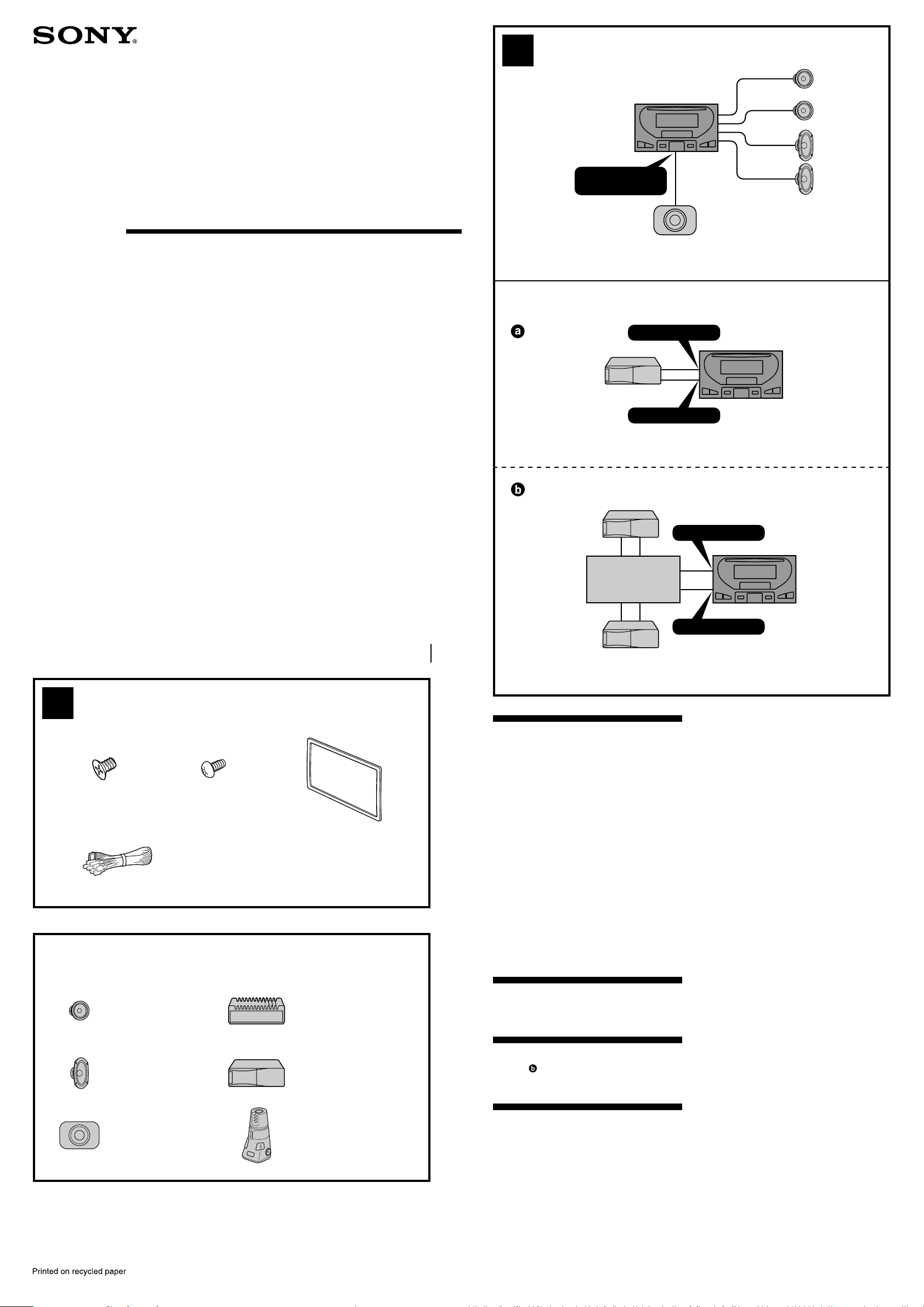
A
Changer Control
Audio Master
Installation/Connections
安裝線路連接
##<KR>##
SUBWOOFER OUT
(MONO)
B
BUS AUDIO IN
BUS CONTROL IN
WX-4500X
Sony Corporation © 2001 Printed in Japan
1
12
× 6
4
Equipment used in illustrations (not supplied)
插圖中的裝置(非附送)
##<KR>##
Front speaker
前揚聲器
##<KR>##
Rear speaker
後揚聲器
##<KR>##
Active subwoofer
##<CT>##
##<KR>##
× 6
3
For NISSAN cars only
僅適用 NISSAN 日產牌汽車
##<KR>##
Power amplifier
功率放大器
##<KR>##
CD/MD changer
CD/MD 換碟機
##<KR>##
Rotary commander RM-X4S
旋轉式控制器 RM-X4S
##<KR>##
*I-3-229-007-11*(1)
Source selector*
音源選擇器*
##<KR>##*
Cautions
•This unit is designed for negative ground 12 V
DC operation only.
•Do not get the wires under a screw, or caught
in moving parts (e.g. seat railing).
•Before making connections, turn the car
ignition off to avoid short circuits.
•Connect the yellow and red power input leads
only after all other leads have been connected.
•Run all ground wires to a common ground
point.
•Be sure to insulate any loose unconnected
wires with electrical tape for safety.
•The use of optical instruments with this
product will increase eye hazard.
Notes on the power supply cord (yellow)
•When connecting this unit in combination with
other stereo components, the connected car
circuit’s rating must be higher than the sum of
each component’s fuse.
•When no car circuits are rated high enough,
connect the unit directly to the battery.
Parts Iist (1)
The numbers in the list are keyed to those in the
instructions.
Connection example (2)
Tip (2-B- )
For connecting two or more changers, the source
selector XA-C30 (optional) is necessary.
Connection diagram (3)
When insert the each connector, be sure to insert
it securely, as vibration through driving may
cause a poor connection.
1 To a metal surface of the car
First connect the black ground lead, then
connect the yellow and red power input leads.
2 To the power antenna control lead or power
supply lead of antenna booster amplifier
Notes
• It is not necessary to connect this lead if there
is no power antenna or antenna booster, or
with a manually-operated telescopic antenna.
• When your car has a built-in FM/AM antenna in
the rear/side glass, see “Notes on the control
and power supply leads.”
BUS AUDIO IN
BUS CONTROL IN
* not supplied
非附送
##<KR>##
3 To AMP REMOTE IN of an optional power
amplifier
This connection is only for amplifiers. Connecting
any other system may damage the unit.
4 To the interface cable of a car telephone
5 To a car’s illumination feed
Be sure to connect the black ground lead to it
first.
6 To the +12 V power terminal which is energized
in the accessory position of the ignition key
switch
Notes
• If there is no accessory position, connect to the
+12 V power (battery) terminal which is
energised at all times.
Be sure to connect the black ground lead to it
first.
• When your car has a built-in FM/AM antenna in
the rear/side glass, see “Notes on the control
and power supply leads.”
7 To the +12 V power terminal which is energised
at all times
Be sure to connect the black ground lead to it
first.
Notes on the control and power supply leads
• The power antenna control lead (blue) supplies
+12 V DC when you turn on the tuner.
• When your car has built-in FM/AM antenna in the
rear/side glass, connect the power antenna control
lead (blue) or the accessory power input lead (red)
to the power terminal of the existing antenna
booster. For details, consult your dealer.
• A power antenna without relay box cannot be
used with this unit.
Memory hold connection
When the yellow power input lead is connected,
power will always be supplied to the memory circuit
even when the ignition key is turned off.
Notes on speaker connection
• Before connecting the speakers, turn the unit off.
• Use speakers with an impedance of 4 to 8 ohms,
and with adequate power handling capacities to
avoid its damage.
• Do not connect the speaker terminals to the car
chassis, or connect the terminals of the right
speakers with those of the left speaker.
• Do not connect the ground lead of this unit to the
negative (–) terminal of the speaker.
• Do not attempt to connect the speakers in parallel.
• Connect only passive speakers. Connecting active
speakers (with built-in amplifiers) to the speaker
terminals may damage the unit.
• To avoid a malfunction, do not use the built-in
speaker wires installed in your car if the unit shares
a common negative (–) lead for the right and left
speakers.
• Do not connect the unit’s speaker cords to each
other.
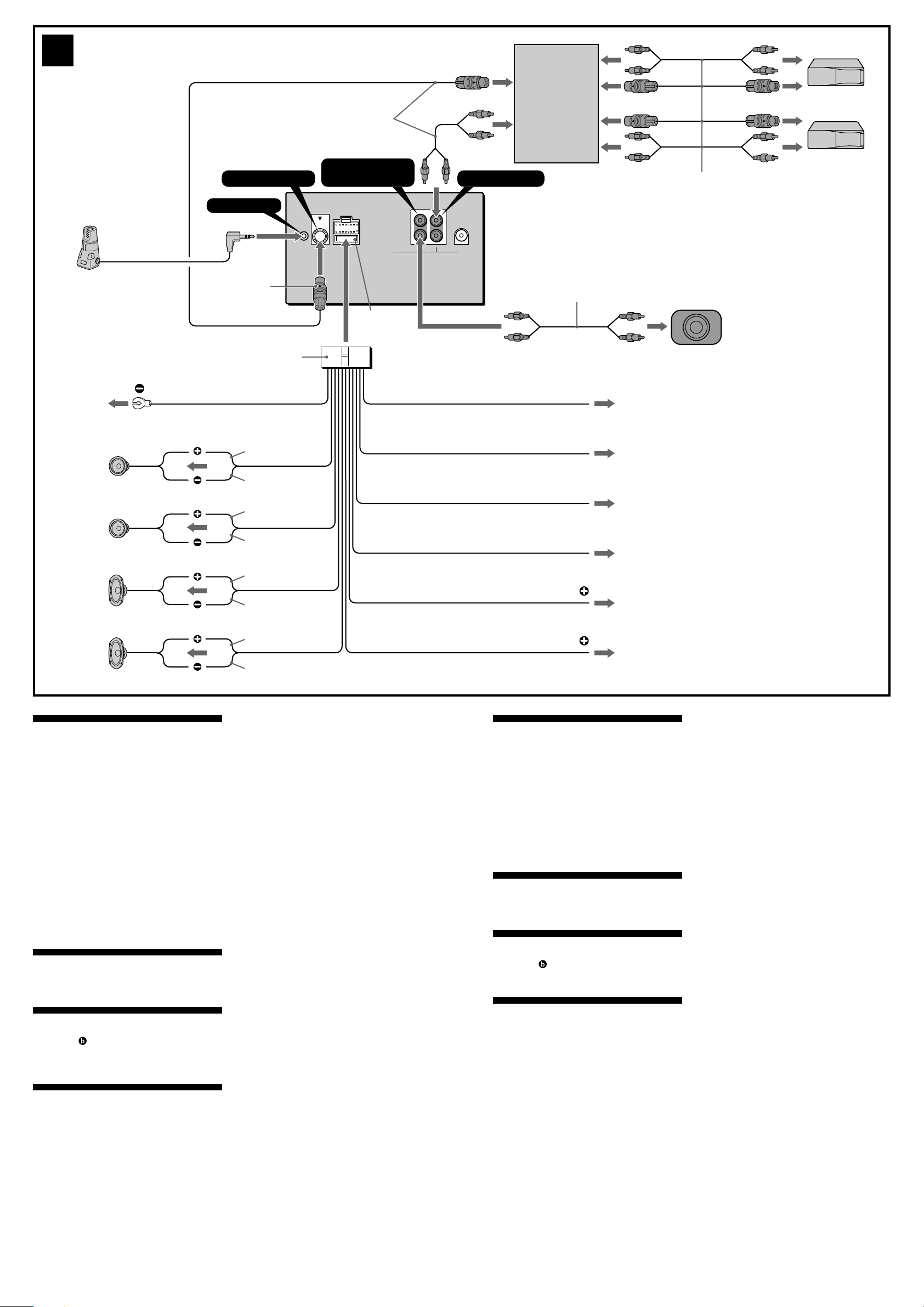
3
1
Left
左
#<KR>#
Right
右
#<KR>#
Left
左
#<KR>#
Right
右
#<KR>#
BUS CONTROL IN
REMOTE IN
2
*
White
白色
##<KR>##
White/black striped
白黑條紋
##<KR>##
Gray
灰色
##<KR>##
Gray/black striped
灰黑條紋
##<KR>##
Green
綠色
##<KR>##
Green/black striped
綠黑條紋
##<KR>##
Purple
紫色
##<KR>##
Purple/black striped
紫黑條紋
##<KR>##
Supplied with XA-C30
附帶於 XA-C30
##<KR>##
SUBWOOFER OUT
4
Black
黑色
#<KR>#
(MONO)
SUB WOOFER BUS AUDIO
Fuse (10 A)
保險絲(10 A)
##<KR>##
Blue
藍色
##<KR>##
Blue/white striped
藍白條紋
##<KR>##
Light blue
##<CT>##
##<KR>##
Orange/white striped
##<CT>##
##<KR>##
Red
紅色
##<KR>##
Yellow
黃色
##<KR>##
MONO
MONO
L
R
OUT IN
Source selector
音源選擇器*
##<KR>##*
BUS AUDIO IN
Max. supply current 0.1 A
最大電流 0.1 A
##<KR>##
Max. supply current 0.3 A
最大電流 0.3 A
##<KR>##
ILLUMINATION
1
*
1
1
RCA pin cord (not supplied)
RCA 針型插頭電線(非附送)
##<KR>##
ANT REM
AMP REM
ATT
2
3
4
5
6
7
Supplied with the CD/MD changer
附帶於 CD/MD 換碟機
##<KR>##
1
*
not supplied
2
*
Connect the Bus cable to its
terminal with the unit’s V mark
and the Bus cable’s v mark
aligned.
1
*
非附送
2
*
##<CT>##
1
*
##<KR>##
2
*
##<KR>##
警告
• 本機祇能使用負極接地 12 V 直流電源。
• 不要使導線夾在螺栓下,或繞掛在移動部件上
(如:座椅扶手上)。
• 進行連接之前,請先關閉汽車的點火器,以避免
短路。
• 黃色和紅色電源輸入導線必須在所有其它導線都
連接完畢以後才連接。
• 將所有地線都連接到同一接地點。
• 為了安全,請確認把沒有連接的導線用電器膠帶
包紮進行絕緣。
電源導線須知(黃色)
• 將本機與其它立體聲裝置相連接時,所連接的
汽車電路容量必須大於每個裝置保險絲容量的
總和。
• 當汽車電路容量不夠大時,請將本機直接與電
池相連接。
零件一覽表(1)
圖示數字與說明書中的數字是一致的。
線路連接圖例(2)
提示
(2-B- )
若要連接 2 台或 2 台以上換碟機時,必須使用音源選擇
器 XA-C30(選購件)。
線路連接圖(3)
##<CT>##
1 至汽車的金屬表面
首先連接黑色接地導線,然後再連接黃色和紅色電源輸
入導線。
2 至電動天線控制導線或天線升壓放大器的電源導線
註
•
如無電動天線、增壓器或手動操作的伸縮天線,便
不需連接此導線。
•
您的汽車的後玻璃窗中如果有內置 FM/AM 天線,即
請參看“控制和電源線須知”。
3 至選購的功率放大器的 AMP REMOTE IN(放大器遙控
輸入)
本連接僅用於放大器。連接任何其它系統可能會損壞本
機。
4 ##<CT>##
5 ##<CT>##
##<CT>##
6 至在點火鑰匙的輔助位置上通電的 +12 V 電源端子
註
•
若沒有輔助位置,則請連接至常時通電的 +12 V 電
源(電池)端子。
務請首先將黑色接地導線與其連接。
•
您的汽車的後玻璃窗中如果有內置 FM/AM 天線,即
請參看“控制和電源線須知”。
7 至常時都通電的 +12 V 電源端子
務請首先將黑色接地導線與其連接。
控制和電源線須知
•
接通調諧器電源時,電動天線的控制導線(藍色)便
能提供 +12 V 直流電。
•
若您的汽車後玻璃窗上有內置 FM/AM 天線,須將電動
天線控制導線(藍色)或輔助電源輸入導線(紅色)
連接到現有天線放大器上的電源端子上。詳細內容請
向銷售商諮詢。
•
本機不能使用不具備繼電箱的電動天線。
保持記憶的線路連接法
當連接好黃色電源輸入導線時,即使汽車發動機點火鑰匙
被轉在電源切斷之處,電源仍繼續將電流供給記憶用電路,
以保持所記憶著的數據。
連接揚聲器時的注意事項
•
連接揚聲器電線以前,請先切斷本機電源。
•
使用阻抗為 4-8Ω 且具有充分功率處理容量的揚聲
器,以免損壞揚聲器。
•
不要將揚聲器端子連接到汽車底盤上或將右揚聲器端
子與左揚聲器端子相連接。
•
切勿將本機的接地導線連接至揚聲器的負(-)接線柱。
•
揚聲器不可以並聯連接。
•
請僅連接無源揚聲器。若將有源揚聲器(帶內置放大
器)連接到揚聲器端子上會損壞本機。
•
##<CT>##
•
##<CT>##
##<KR>##
• ####
• ####
• ####
• ####
• ####
• ####
####
• ####
• ####
##<KR>##(1)
####
##<KR>##(2)
####
(2-B- )
####
##<KR>##(3)
##<KR>##
1 ####
####
2 ####
####
•
####
•
####
3 ####
####
4 ####
5 ####
####
6 ####
####
•
####
####
•
####
7 ####
####
####
•
####
•
####
•
####
####
####
####
•
####
•
####
•
####
•
####
•
####
•
####
•
####
 Loading...