

Sony WEGA KLV-21SR2 Operating Manual
LCD Color TV
4-099-415-11 (1)
Operating Instructions
Before operating the unit, please read this manual thoroughly
and retain it for future reference.
Owner’s Record
The model and serial numbers are located at the rear of the TV, on the backside of
the rear cover, on the sticker, and also on the TV box (white label). Record these
numbers in the spaces provided below. Refer to them whenever you call upon your
Sony dealer regarding this product.
Model No. ________________
Serial No. ________________
KLV-21SR2
© 2003 Sony Corporation
WARNING
To reduce the risk of fire or shock hazard,
do not expose the TV to rain or moisture.
CAUTION
RISK OF ELECTRIC SHOCK
DO NOT OPEN
ATTENTION
RISQUE DE CHOC ELECTRIQUE,
NE PAS OUVRIR
PRECAUCION
RIESGO DE CHOQUE ELECTRICO
NO ABRIR
CAUTION : TO REDUCE THE RISK OF ELECTRIC SHOCK,
DO NOT REMOVE COVER (OR BACK).
NO USER-SERVICEABLE PARTS INSIDE.
REFER SERVICING TO QUALIFIED SERVICE PERSONNEL.
This symbol is intended to alert the user to the presence
of uninsulated “dangerous voltage” within the product’s
enclosure that may be of sufficient magnitude to
constitute a risk of electric shock to persons.
This symbol is intended to alert the user to the
presence of important operating and maintenance
(servicing) instructions in the literature
accompanying the appliance.
CAUTION
TO PREVENT ELECTRIC SHOCK, MATCH WIDE BLADE OF
PLUG TO WIDE SLOT, FULLY INSERT.
NOTIFICATION
This equipment has been tested and found to comply with the limits for a
Class B digital device pursuant to Part 15 of the FCC Rules. These limits
are designed to provide reasonable protection against harmful interference
in a residential installation. This equipment generates, uses, and can radiate
radio frequency energy and, if not installed and used in accordance with
the instructions, may cause harmful interference with radio
communications. However, there is no guarantee that interference will not
occur in a particular installation. If this equipment does cause harmful
interference to radio or television reception, which can be determined by
turning the equipment off and on, the user is encouraged to try to correct
the interference by one or more of the following measures:
– Reorient or relocate the receiving antennas.
– Increase the separation between the equipment and receiver.
– Connect the equipment into an outlet on a circuit different from that to
which the receiver is connected.
– Consult the dealer or an experienced radio/TV technician for help.
You are cautioned that any changes or modifications not expressly
approved in this manual could void your warranty and your authority
to operate this equipment.
Safety
– Operate the TV only on 120 V AC.
– The plug is designed, for safety purposes, to fit into the wall outlet
only one way. If you are unable to insert the plug fully into the outlet,
contact your dealer.
– If any liquid or solid object should fall inside the cabinet, unplug the
TV immediately and have it checked by qualified service personnel
before operating it further.
– If you will not be using the TV for several days, disconnect the power
by pulling the plug itself. Never pull on the cord.
Installing
– To prevent internal heat buildup, do not block the ventilation
openings.
– Do not install the TV in a hot or humid place, or in a place subject to
excessive dust or mechanical vibration.
CAUTION
The following SONY appliance for use only with the following WALLMOUNT BRACKET. Use with other WALL-MOUNT BRACKET is
capable of resulting in instability causing possible injury.
SONY APPLIANCE MODEL NO.
KLV-21SR2
WALL-MOUNT BRACKET MODEL NO.
SU-W210
SONY Corp.
Note on Caption Vision
This television receiver provides display of television closed captioning
in accordance with §15.119 of the FCC rules.
Note to CATV system installer
This note is provided to call the CATV system installer’s attention to
Article 820-40 of the NEC that provides guidelines for proper grounding
and, in particular, specifies that the cable ground shall be connected to
the grounding system of the building, as close to the point of cable entry
as practical.
Use of this television receiver for other than private viewing of programs
broadcast on UHF, VHF, transmitted by cable companies or satellite for
the use of the general public may require authorization from the
broadcaster/cable company and/or program owner.
As an ENERGY STAR® Partner, Sony
Corporation has determined that this
product meets the ENERGY STAR
®
guidelines for energy efficiency.
WOW, SRS and symbol are trademarks of SRS Labs, Inc.
WOW technology is incorporated under license from SRS Labs, Inc.
2
Important Safety Instructions
1 Read these instructions.
2 Keep these instructions.
3 Heed all warnings.
4 Follow all instructions.
5 Do not use this apparatus near water.
6 Clean only with dry cloth.
7 Do not block any ventilation openings. Install in
accordance with the manufacturer’s
instructions.
8 Do not install near any heat sources such as
radiators, heat registers, stoves, or other
apparatus (including amplifiers) that produce
heat.
9 Do not defeat the safety purpose of the
polarized or grounding-type plug. A polarized
plug has two blades with one wider than the
other. A grounding type plug has two blades
and a third grounding prong. The wide blade or
the third prong are provided for your safety. If
the provided plug does not fit into your outlet,
consult an electrician for replacement of the
obsolete outlet.
10 Protect the power cord from being walked on or
pinched particularly at plugs, convenience
receptacles, and the point where they exit from
the apparatus.
11 Only use attachments/accessories specified by
the manufacturer.
Handling the LCD screen
s Do not leave the LCD screen facing the sun as it can damage the LCD
screen. Take care when you place the TV by a window.
s Do not push on or scratch the LCD screen. Do not place a heavy object
on the LCD screen. This may cause the screen to lose uniformity or
cause LCD panel malfunctions.
s If the TV is used in a cold place, a smear may appear on the screen.
This is not a malfunction. The screen returns to normal as the
temperature rises to a normal operating level.
s If a still picture is displayed for a long time, a ghosting may occur for a
while. The ghosting will eventually disappear.
s The LCD panel becomes warm during operation. This is not a
malfunction.
Note on the LCD (Liquid Crystal Display)
Please note that the LCD screen is made with high-precision technology.
However, black points or bright points of light (red, blue, or green) may
appear constantly on the LCD screen, and irregular colored stripes or
brightness may appear on the LCD screen. This is not a malfunction.
(Effective dots: more than 99.99%)
Handling of Broken Glass and Liquid Crystal Leakage
If the LCD panel gets damaged, crystalline liquid leakage may occur, or
scattered broken glass may result. Do not touch broken glass or crystalline
liquid (which is toxic), with bare hands as cuts or poisoning/skin irritation
may occur. Also, do not let glass fragments or leaked crystalline liquid get
into your eyes or mouth. Should either contact your eyes or mouth, rinse
the contacted area thoroughly with water and consult your doctor.
Fluorescent Lamp
This TV uses a special fluorescent lamp as its light source. If the screen
image becomes dark, flickers or does not appear, the fluorescent lamp has
run down and should be replaced. For replacement, consult qualified
service personnel.
Disposal of the TV
s Do not dispose of the TV with general household waste.
s The LCD contains a small amount of liquid crystal and mercury. The
fluorescent lamp used in this TV also contains mercury. Follow your
local ordinances and regulations for disposal.
12 Use only with the cart,
stand, tripod, bracket, or
table specified by the
manufacturer, or sold with
the apparatus. When a cart
is used, use caution when
moving the cart/apparatus
combination to avoid
injury from tip-over.
13 Unplug this apparatus during lightning storms
or when unused for long periods of time.
14 Refer all servicing to qualified service personnel.
Servicing is required when the apparatus has
been damaged in any way, such as powersupply cord or plug is damaged, liquid has been
spilled or objects have fallen into the apparatus,
the apparatus has been exposed to rain or
moisture, does not operate normally, or has
been dropped.
3

4

Table of Contents
Table of Contents
Installing and Connecting the TV
Unpacking ..........................................................6
Inserting Batteries into the Remote Control...6
Connector Types................................................6
Identifying Front and Rear Connectors.......... 7
Basic Connections (Connecting Cable TV or
an Antenna)................................................... 8
Removing the rear cover ...........................8
Attaching the rear cover ............................8
Connecting directly to cable
or an antenna ........................................8
Cable box connections ..............................8
Connecting the Power Cord .............................9
Bundling cords and cables ......................10
Adjusting the viewing angle of the TV ...11
Carrying the TV ......................................11
Connecting a VCR and Cable TV..................12
Connecting a Satellite Receiver......................13
Connecting a Satellite Receiver with a VCR ....14
Connecting an Audio Receiver....................... 15
Connecting a DVD Player with Component
Video Connectors .......................................16
Connecting a DVD Player with A/V
Connectors ..................................................17
Using the Video Label Feature.......................29
Operating Video Equipment with Your TV
Remote Control ..........................................30
Programming the remote control ............30
Operating optional equipment.................32
Using Favorite Channels.................................33
Setting your favorite channels................. 33
Watching favorite channels.....................34
Using the Channel Label Feature ..................34
Using Advanced Features
Using the Menu................................................ 36
Adjusting the Picture Quality ........................ 37
Adjusting the Sound Quality ..........................39
Selecting Stereo or Bilingual Programs.........41
Selecting stereo or bilingual programs
using the menu ................................... 41
Using the Parental Control Feature...............42
Activating the Parental Control feature ....42
Selecting a Custom Rating ...................... 44
What the Ratings Mean .................................. 46
Ratings in the U.S.A. .............................. 46
Ratings in Canada ...................................48
Turning Off the TV Automatically................ 50
Connecting a Digital Satellite Receiver .........18
Connecting a Digital TV Receiver ................. 19
Setting the Channels........................................20
Selecting the On-screen Menu Language......22
Watching the TV
Watching the TV ............................................. 23
Watching with closed caption .................24
Selecting the Picture Mode .............................24
Selecting the Effect Mode ...............................25
Using the 16:9 Enhanced Feature ..................26
Using the Freeze Function ..............................27
Setting the Video Inputs..................................28
Additional Information
Troubleshooting...............................................51
Self-diagnosis function ........................... 51
Trouble symptoms and remedies ............51
Specifications ................................................... 53
Index to parts and controls.............................54
TV Front Panel........................................54
Remote Control .......................................55
Index .................................................................56
5
Installing and Connecting the TV
Installing and
Connecting the
TV
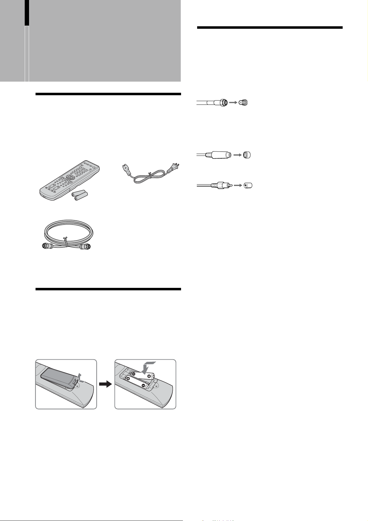
Unpacking
When you unpack this unit, make sure it includes the
following:
Remote control (1) and
size AA batteries (2)
75-ohm coaxial cable (1)
AC power cord (1)
Connector Types
You may find it necessary to use some of the
following connector types during set up.
Supplied 75-ohm coaxial cable
Screw-on type
Screw into connection.
S VIDEO cable
High quality video cable for enhanced picture quality
Align guides and push into
connection.
AUDIO/VIDEO cable
Push into connection.
VIDEO - Yellow
AUDIO (Left) - White
AUDIO (Right) - Red
Operating Instructions
Warranty Card
Product Registration
Inserting Batteries into the Remote Control
Insert two size AA batteries (supplied) by matching
the + and – on the batteries to the diagram inside the
remote control’s battery compartment.
Some DVD players are equipped with the following
three video connectors:
Y - Green
B (CB, Cb or B-Y) - Blue
P
R (CR, Cr or R-Y) - Red
P
Notes
• Remove the batteries to avoid damage from possible battery
leakage whenever you anticipate that the remote control will
not be used for an extended period.
• Handle the remote control with care. Avoid dropping it,
getting it wet, or placing it in direct sunlight, near a heater or
where the humidity is high.
• Your remote control can be programmed to operate most video
equipment (See “Operating Video Equipment with Your TV
Remote Control” on page 30).
6
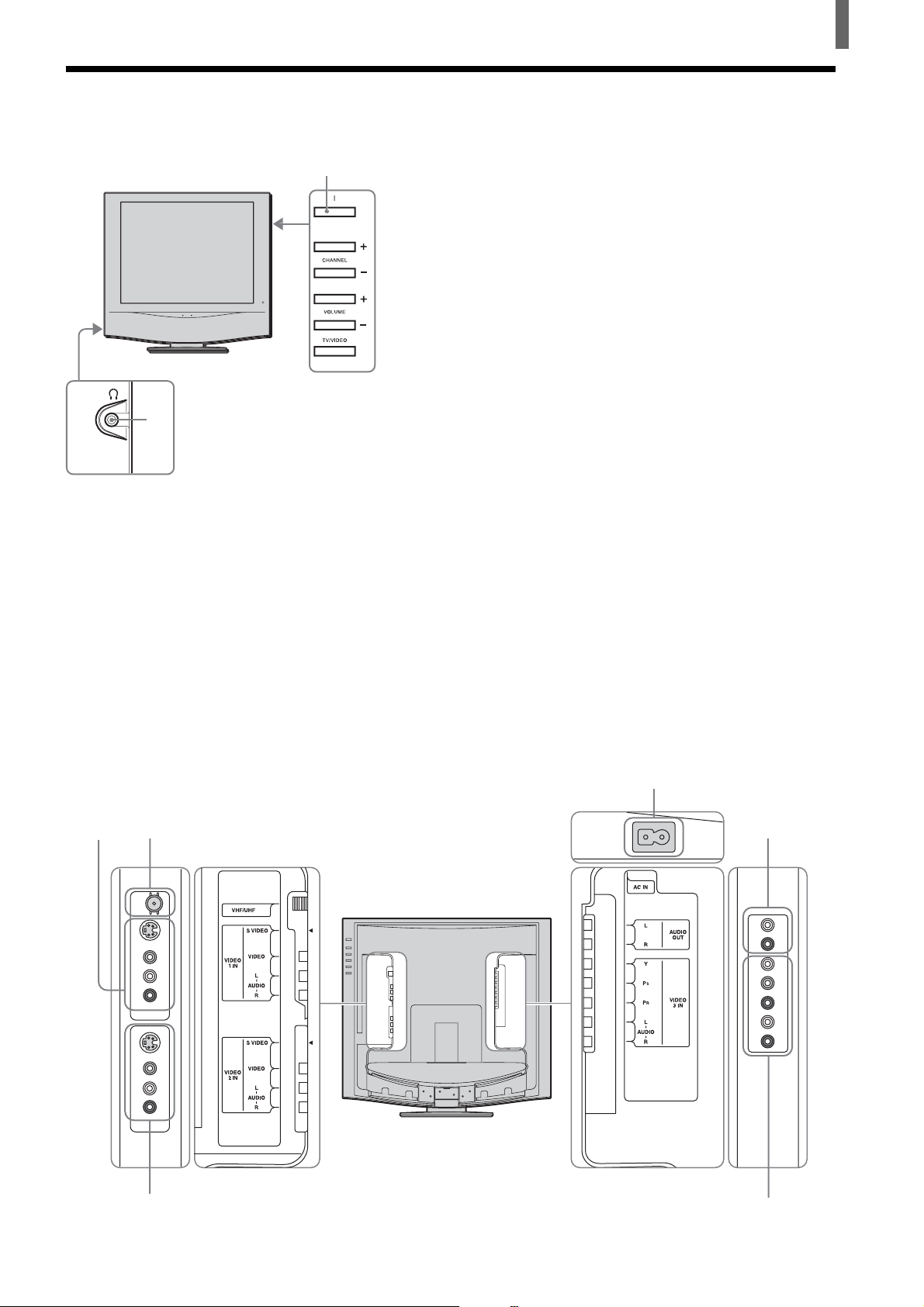
Identifying Front and Rear Connectors
Installing and Connecting the TV
TV front panel
1
2
Side view
1 POWER button (page 20)
2 Headphones jack
Connects to your headphones.
If your headphones do not match the jack, use a
suitable plug adaptor (not supplied).
3 VHF/UHF (pages 8, 12 - 14)
Connects to your VHF/UHF antenna or cable.
4 VIDEO 1 IN (pages 12 - 14, 17)
Connects to the output jacks of your VCR or
other video equipment.
5 VIDEO 2 IN (page 12 - 14, 17)
Connects to the output jacks of your VCR or
other video equipment.
6 AC IN (page 9)
Connects the supplied AC power cord.
7 AUDIO OUT (page 15)
Connects to the input jacks of your audio
equipment.
Audio output through the AUDIO OUT jacks is
available only when the TV’s speaker is off (See
page 15).
8 VIDEO 3 IN
B, PR input jacks (pages 16, 18, 19)
Y, P
Connects to the component video connectors
B/CR, Y/B-Y/R-Y, or Y/PB/PR) of your
(Y/C
DVD player or other video equipment such as a
Digital Satellite Receiver and Digital TV
Receiver.
AUDIO (L/R) input jacks (pages 16, 18, 19)
Connects to the audio output jacks of your DVD
player or other video equipment such as a
Digital Satellite Receiver and Digital TV
Receiver.
Rear of TV
4
6
3 7
Side view
5
8
Side view
7
Installing and Connecting the TV
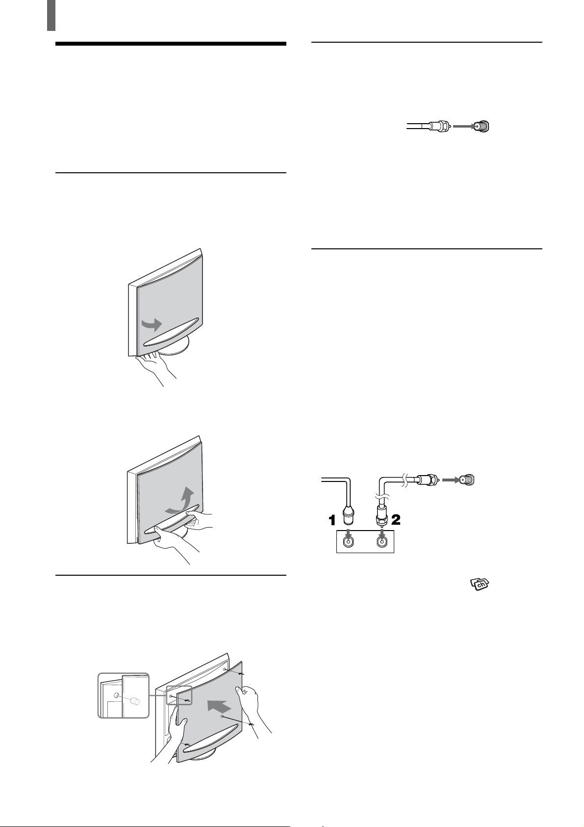
Basic Connections (Connecting Cable TV or an Antenna)
When connecting an antenna or cables, remove the
rear cover of the TV beforehand.
Removing the rear cover
1 Hold the lower right (or left) corner of the back
cover as illustrated below and pull it towards
you. Do the same to the remaining left (or right)
corner.
Connecting directly to cable or an
antenna
VHF only or VHF/UHF or cable
75-ohm coaxial
cable (supplied)
VHF/UHF
Note
It is strongly recommended to connect the antenna using a 75-
ohm coaxial cable to get optimum picture quality. A 300-ohm
twin lead cable can be easily affected by radio noise and the like,
resulting in signal deterioration. If you use a 300-ohm twin lead
cable, keep it away as far as possible from the TV.
Rear of TV
Cable box connections
Use this hookup if:
•You subscribe to a cable TV system that uses
scrambled or encoded signals requiring a cable
box to view all channels, and
•You do not intend to hook up any other audio or
video equipment to your TV.
2 Hold the bottom edge of the cover with both
hands as illustrated and lift upwards.
Attaching the rear cover
Hold the rear cover as illustrated below, fitting the
four pegs on the rear cover into the corresponding
holes on the TV, then push the rear cover back onto
the TV.
1 Connect the coaxial connector from your cable
service to the cable box’s IN jack.
2 Using the supplied 75-ohm coaxial cable,
connect the cable box’s OUT jack to the TV’s
VHF/UHF jack.
75-ohm coaxial
Cable
IN
Cable box
Also, set “Cable” to “On” in the
menu (See page 20).
Tips
• Your Sony remote control can be programmed to operate your
cable box (See “Programming the remote control” on page
30).
• To change channels using the cable box, set your TV to
channel 3 or 4 depending on the cable box channel output.
• If you will be controlling all channel selection through your
cable box, consider using the Channel Fix feature to set your
TV to channel 3 or 4 (See page 21).
cable (supplied)
Rear of TV
VHF/UHF
OUT
(Channel)
8
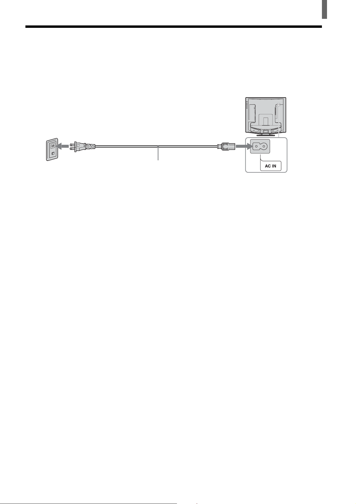
Connecting the Power Cord
Complete other connections prior to connecting the power cord.
1 Connect the power cord to the AC IN connector of the TV.
2 Connect the other plug of the power cord to a wall outlet.
Installing and Connecting the TV
Wall outlet
For 120 V AC
AC power cord (supplied)
9
Installing and Connecting the TV
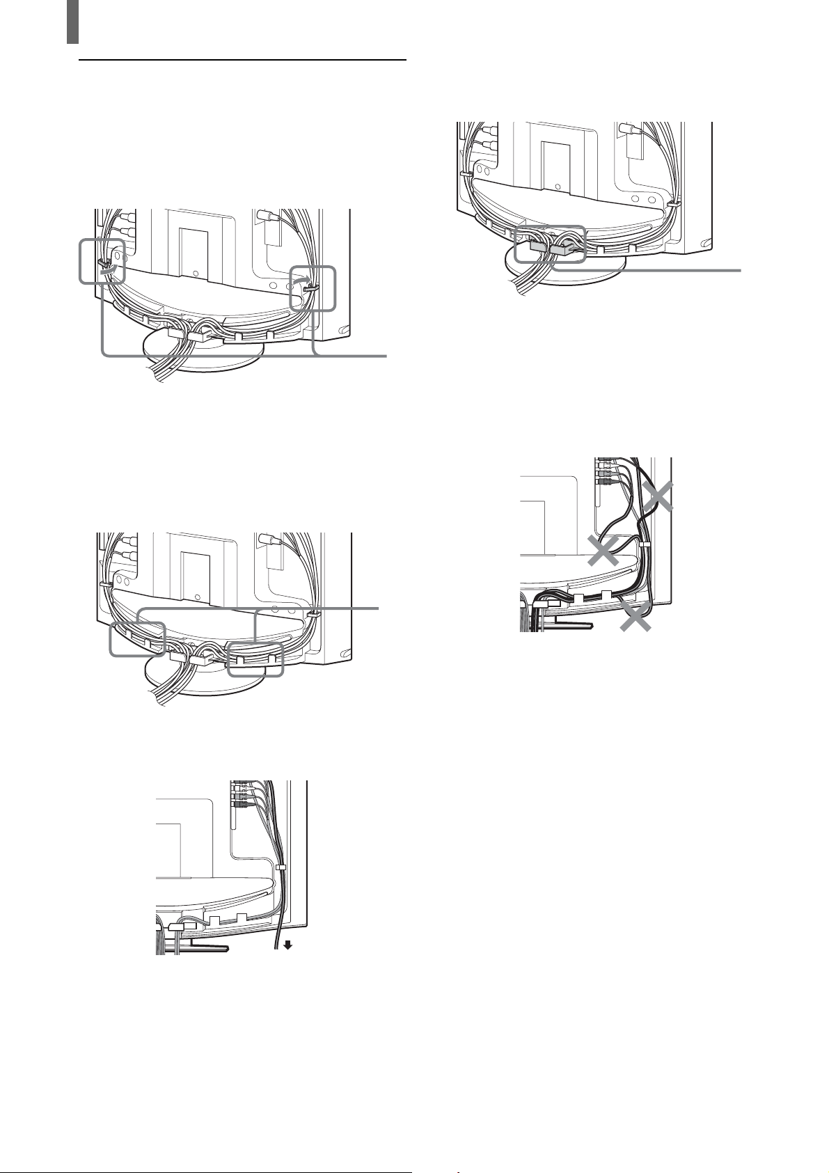
Bundling cords and cables
You can organize the cables in the back of the TV.
1 Bundle the cables and secure them with the clips
on both sides of the TV.
Note
It may not be possible to fasten with clips if cables are too
thick.
Clips
3 Gather the cables from both sides together and
secure them with the clip at the bottom.
Clip
Note
It may not be possible to fasten with clips if cables are too
thick.
Note
If the cables are not neatly stored in the grooves, you may not be
able to attach the rear cover.
2 Pass the cables through the grooves. Be sure to
place the cables inside the tabs at the bottom of
the TV.
Note
If all the cables cannot be stored inside, you may leave
some of them hanging down on both sides of the TV.
Tabs
10
Installing and Connecting the TV
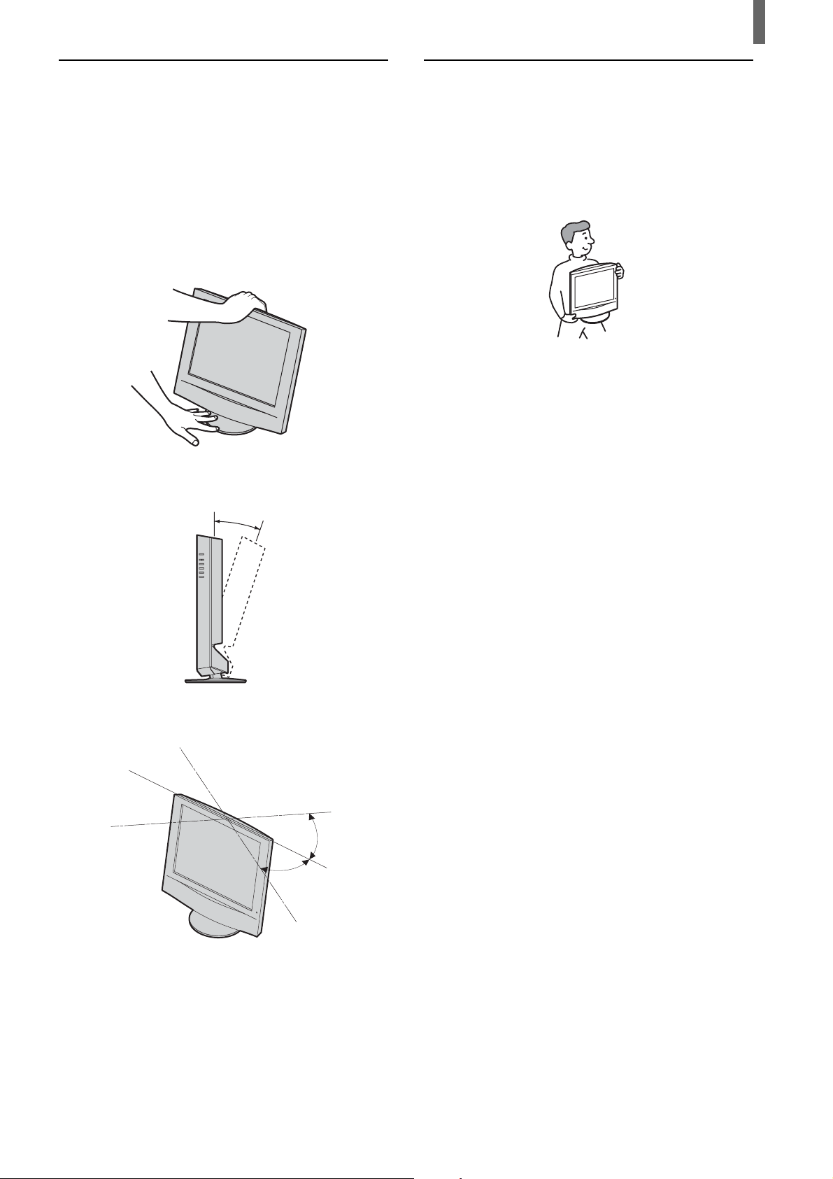
Adjusting the viewing angle of the TV
You can adjust the angle to avoid the reflection of
light and get a better view of the TV.
Note
When adjusting the angle, steady the base of the stand with your
hand to prevent the TV from becoming separated from the stand.
Be careful not to get your fingers caught between the TV and the
stand.
Carrying the TV
When carrying the TV, hold it as shown in the
diagram below. Do not hold only by the rear cover.
As the rear cover is designed to come off, doing so
may cause you to drop the TV, resulting in damage
to the TV or cause injury.
Backward direction
15°
Horizontal direction
30°
30°
11
Installing and Connecting the TV
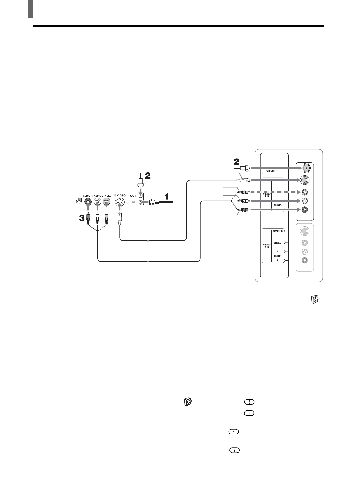
Connecting a VCR and Cable TV
Use this hookup if:
•You have cable TV that does not require a cable box.
Disconnect all power sources before making any connections.
1 Connect the CATV cable to the VCR’s IN jack.
2 Using the supplied 75-ohm coaxial cable, connect the VCR’s OUT jack
to the TV’s VHF/UHF jack.
3 Using AUDIO and S VIDEO cables, connect the VCR’s AUDIO and S
VIDEO OUT jacks to the TV’s AUDIO and S VIDEO IN jacks.
Rear of TV
VCR
75-ohm coaxial
cable (supplied)
Cable
S VIDEO cable
(not supplied)
AUDIO cable
(not supplied)
Note
To watch the pictures input from the S VIDEO input jack, set “Auto YC” to “On” in the
(Setup) menu (See below).
Tips
• You can also use the VIDEO 2 IN jacks to connect your VCR.
• If your VCR is not equipped with S VIDEO, use a VIDEO cable (yellow) instead of the S
VIDEO cable.
75-ohm coaxial
cable (supplied)
S VIDEO
VIDEO (yellow)
AUDIO-L (white)
AUDIO-R (red)
12
When connecting both VIDEO OUT and S VIDEO OUT
You can select the jack the TV receives the input signal from on the menu screen.
The TV is factory set to receive S VIDEO input signals.
1 Press TV/VIDEO repeatedly to select VIDEO 1 IN.
2 Press MENU.
3 Press V/v to select (Setup), then press .
4 Press V/v to select “Auto YC,” then press .
5 To watch the pictures input from the S VIDEO input jack:
Press V/v to select “On,” then press
To watch the pictures input from the VIDEO input jack:
Press V/v to select “Off,” then press .
.
6 Press MENU to exit the menu screen.
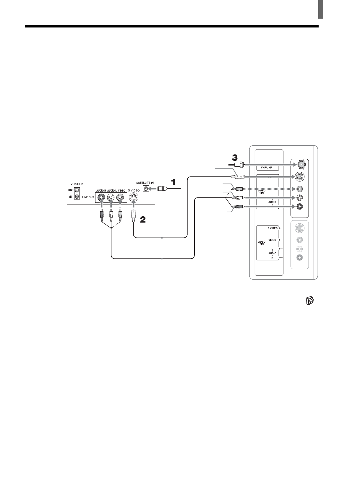
Connecting a Satellite Receiver
Disconnect all power sources before making any connections.
1 Connect the satellite antenna cable to the satellite receiver’s SATELLITE
IN jack.
2 Using AUDIO and S VIDEO cables, connect the satellite receiver’s AUDIO
and S VIDEO OUT jacks to the TV’s AUDIO and S VIDEO IN jacks.
3 Connect the supplied 75-ohm coaxial cable from your cable or antenna to the
TV’s VHF/UHF jack.
75-ohm coaxial cable (supplied)
Satellite receiver
Satellite
antenna
cable
S VIDEO cable
(not supplied)
S VIDEO
VIDEO (yellow)
AUDIO-L (white)
Installing and Connecting the TV
Rear of TV
AUDIO-R (red)
AUDIO cable
(not supplied)
Note
To watch the pictures input from the S VIDEO input jack, set “Auto YC” to “On” in the
(Setup) menu (See page 12).
Tips
• You can also use the VIDEO 2 IN jacks to connect your satellite receiver.
• If your satellite receiver is not equipped with S VIDEO, use a VIDEO cable (yellow)
instead of the S VIDEO cable.
13
Installing and Connecting the TV
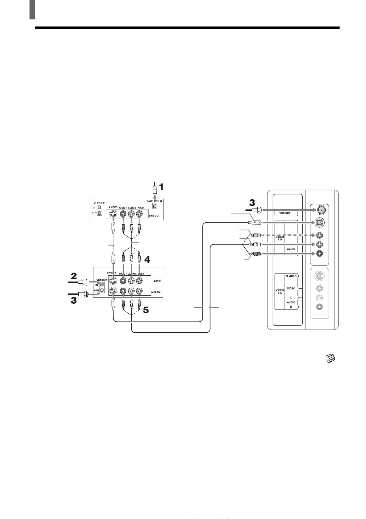
Connecting a Satellite Receiver with a VCR
Disconnect all power sources before making any connections.
1 Connect the satellite antenna cable to the satellite receiver’s SATELLITE
IN jack.
2 Connect the CATV cable to the VCR’s VHF/UHF IN jack.
3 Using the supplied 75-ohm coaxial cable, connect the VCR’s OUT jack
to the TV’s VHF/UHF jack.
4 Using AUDIO and S VIDEO cables, connect the satellite receiver’s
AUDIO and S VIDEO OUT jacks to the VCR’s AUDIO and S VIDEO
IN jacks.
5 Using AUDIO and S VIDEO cables, connect the VCR’s AUDIO and S
VIDEO OUT jacks to the TV’s AUDIO and S VIDEO IN jacks.
Satellite receiver
S VIDEO cable
(not supplied)
Cable
75-ohm
coaxial cable
(supplied)
VCR
Satellite
antenna
cable
75-ohm coaxial
cable (supplied)
S VIDEO
VIDEO (yellow)
AUDIO cable
(not supplied)
S VIDEO cable
(not supplied)
Note
To watch the pictures input from the S VIDEO input jack, set “Auto YC” to “On” in the
(Setup) menu (See page 12).
AUDIO-L (white)
AUDIO-R (red)
AUDIO cable
(not supplied)
Rear of TV
14
Tips
• You can also use the VIDEO 2 IN jacks to connect your VCR.
• Be sure your VCR’s video input is set correctly. Consult your VCR’s operating manual for
instructions.
• Use TV/VIDEO on the remote control to select VIDEO 1 IN to watch satellite TV or to
watch a tape on the VCR (your VCR must be turned on).
• If your VCR or satellite receiver is not equipped with S VIDEO, use a VIDEO cable
(yellow) instead of the S VIDEO cable.
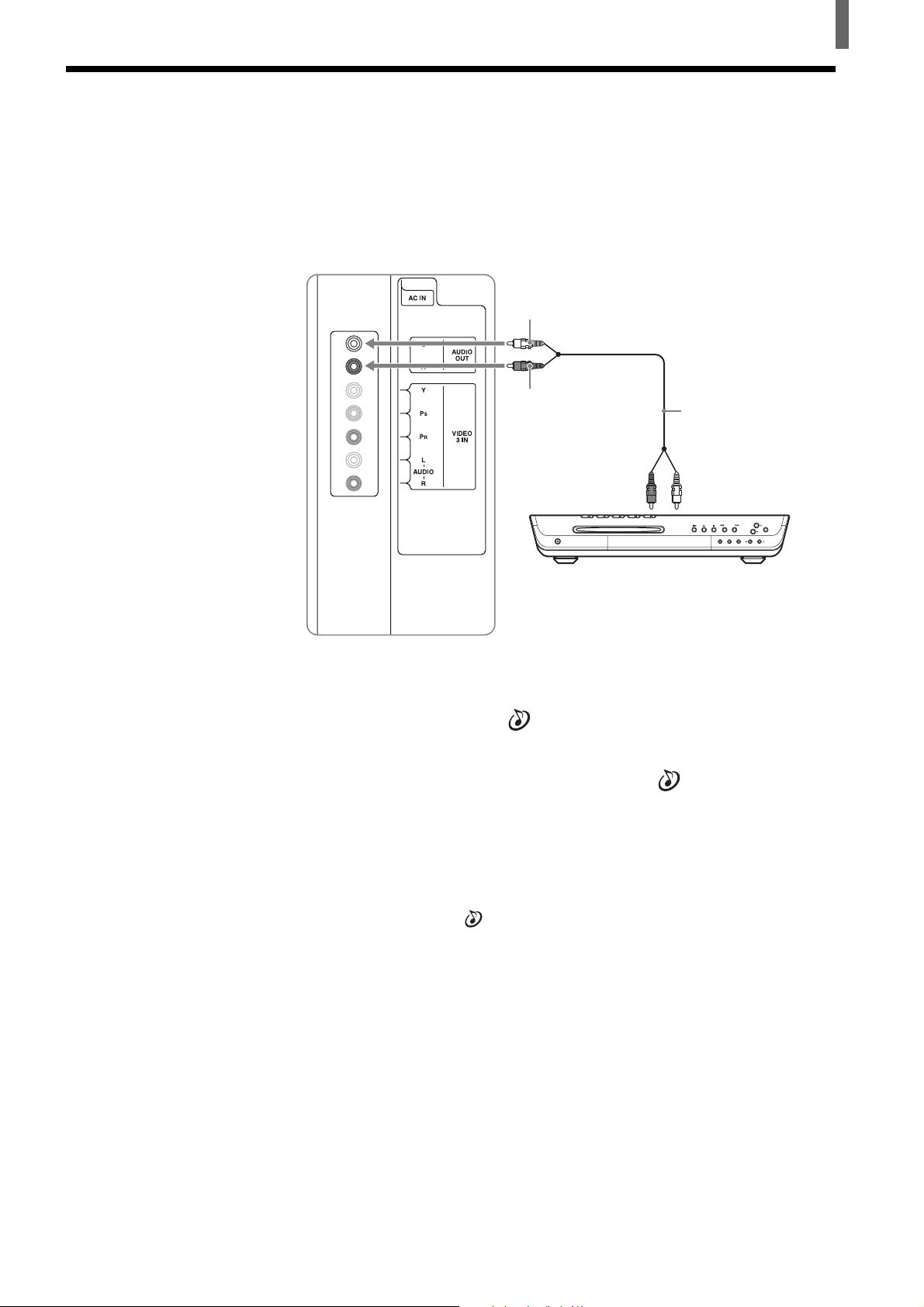
Connecting an Audio Receiver
Disconnect all power sources before making any connections.
Using an AUDIO cable, connect the TV’s AUDIO OUT jacks to the audio
receiver’s AUDIO IN jacks.
Rear of TV
AUDIO-L (white)
Installing and Connecting the TV
AUDIO-R (red)
Audio reciever
(Compact AV system
DAV-FC9, etc)
AUDIO cable
(not supplied)
Audio
input
When using your audio system speakers
Set “Speaker” to “Off” in the
(Audio) menu. The TV’s sound is not
output from the AUDIO OUT jacks when the TV’s speaker is set to on.
You can still control the volume output from your audio system using the
TV’s remote control, by setting “Audio Out” in the
(Audio) menu to
“Variable.”
If you want to adjust the volume through your audio system, set “Audio Out”
to “Fixed.”
Notes
• The video signal is not output through the AUDIO OUT jacks.
• When “Audio Out” in the
check if the speaker volume is moderate before switching “Speaker” from “Off” to “On.”
Otherwise, the speaker volume may get too loud.
(Audio) menu is set to “Variable,” “Speaker” is to “Off,”
15
Installing and Connecting the TV
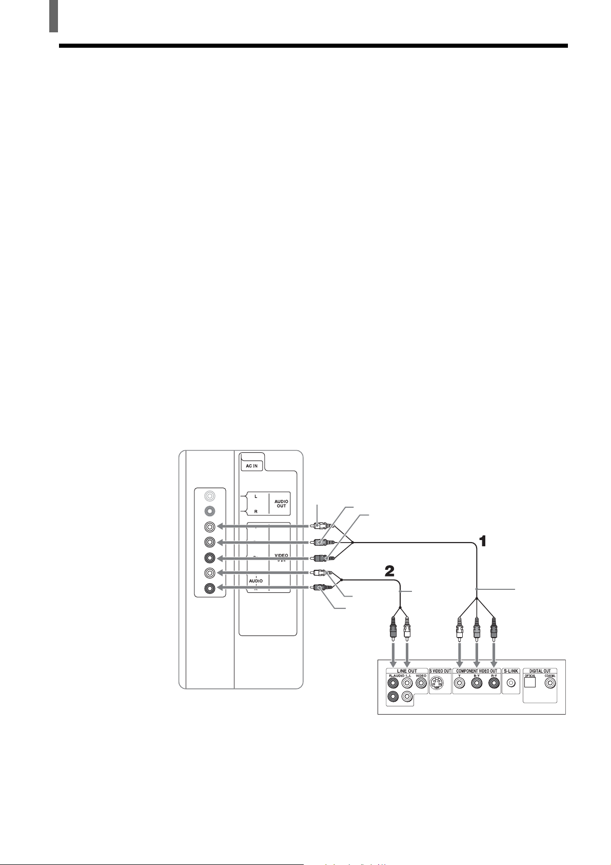
Connecting a DVD Player with Component Video Connectors
This is the preferred hookup to use if:
•Your DVD player has component (Y, B-Y, R-Y) jacks.
Disconnect all power sources before making any connections.
1 Using a component video cable, connect the DVD player’s Y, B-Y and
R-Y jacks to the Y, P
connections.
Note
This TV supports only the 480i and 480p signal format. If the TV receives a signal other
than 480i or 480p, “Non Supported Video Format” appears on the screen.
Tip
The Y, B-Y and R-Y jacks on your DVD player are sometimes labeled as Y, CB and CR,
or Y, PB and PR. If so, connect the cables to the matching colors.
B and PR jacks on the TV. Use the VIDEO 3 IN
2 Using an AUDIO cable, connect the DVD player’s AUDIO OUT jacks to
the TV’s AUDIO IN jacks.
Note
The Y, B-Y and R-Y jacks do not provide audio, so audio cables must be connected to
provide sound.
Rear of TV
Y
PB
PR
AUDIO-L
(white)
AUDIO-R
(red)
AUDIO cable
(not supplied)
Component
video cable
(not supplied)
16
DVD player
Tips
• To take advantage of the Wide Screen Modes, set the TV’s aspect ratio to 16:9 on your
DVD player. For details, refer to the operating instructions supplied with your DVD player.
• Some DVD players are equipped with the three component video connectors: Y-Green, P
(CB, Cb or B-Y) -Blue and PR (CR, Cr or R-Y) -Red.
B
Installing and Connecting the TV
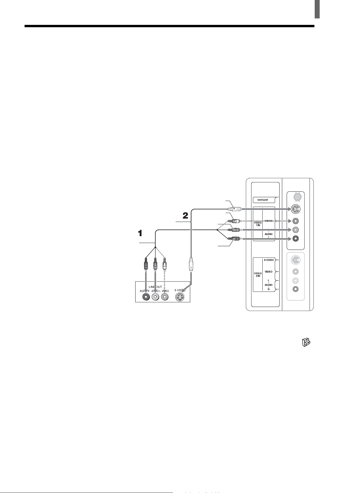
Connecting a DVD Player with A/V Connectors
Use this hookup if:
•Your DVD player does not have component (Y, P
Tip
If your DVD player has component video output connectors, for best picture quality, use the
connection described on page 16.
B, PR) jacks.
Disconnect all power sources before making any connections.
1 Using an AUDIO cable, connect the DVD player’s AUDIO OUT jacks to
the TV’s AUDIO IN jacks.
2 Using an S VIDEO cable, connect the DVD player’s S VIDEO jack to
the TV’s S VIDEO jack.
Rear of TV
S VIDEO
S VIDEO cable
(not supplied)
VIDEO (yellow)
AUDIO-L
(white)
AUDIO cable
(not supplied)
DVD player
Note
To watch the pictures input from the S VIDEO input jack, set “Auto YC” to “On” in the
(Setup) menu (See page 12).
Tips
• You can also use the VIDEO 2 IN jacks to connect your DVD player.
• To take advantage of the Wide Screen Modes, set the TV’s aspect ratio to 16:9 on your
DVD player. For details, refer to the operating instructions supplied with your DVD player.
• Use TV/VIDEO on the remote control to switch to the DVD player input.
• If your DVD player is not equipped with S VIDEO, use a VIDEO cable (yellow) instead of
the S VIDEO cable.
AUDIO-R
(red)
17
Installing and Connecting the TV
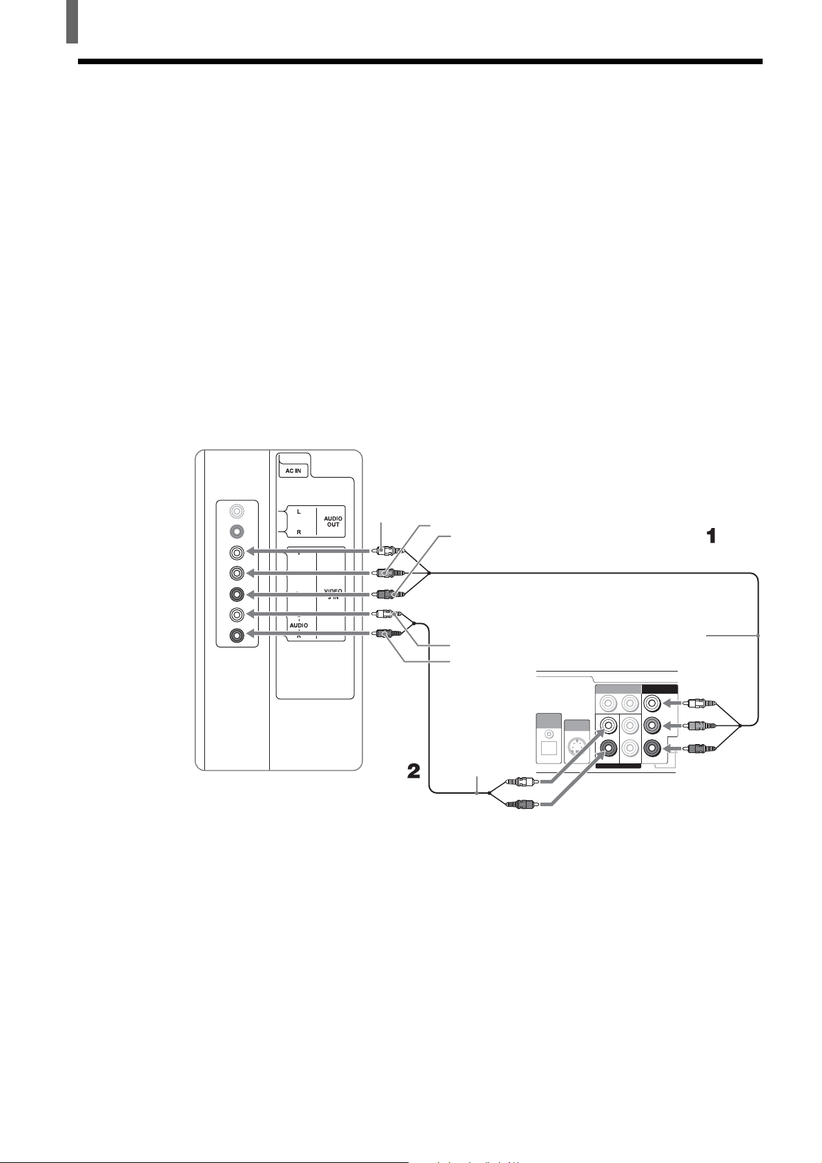
Connecting a Digital Satellite Receiver
Disconnect all power sources before making any connections.
1 Using a component video cable, connect the Digital Satellite Receiver’s
B and PR jacks to the Y, PB and PR jacks on the TV. Use the VIDEO 3
Y, P
IN connections.
Note
This TV supports only the 480i and 480p signal format. If the TV receives a signal other
than 480i or 480p, “Non Supported Video Format” appears on the screen.
2 Using an AUDIO cable, connect the Digital Satellite Receiver’s AUDIO
OUT jacks to the TV’s AUDIO IN jacks.
Note
The Y, PB and PR jacks do not provide audio, so audio cables must be connected to
provide sound.
Rear of TV
Y
PB
PR
AUDIO-L
(white)
AUDIO-R
(red)
AUDIO cable
(not supplied)
Digital Satellite
Receiver
(e.g. SAT-HD200,
SAT-HD300, etc)
S VIDEO
OUT
1
L1 L2
R1
DIGITAL
AUDIO
OUT
OPTICAL
VIDEO OUT
AUDIO OUT
2
R2
Component
video cable
(not supplied)
COMPONENT OUT
(1080i/720p/480p/480i)
Y
Pb
TYPE
Pr
18
 Loading...