

Sony vx724 1 Service Manual
Service Manual
ViewSonic VX724-1
Model No. VS10049
17” Color TFT LCD Display
ViewSonic
(VX724-1_SM Rev. 1b Jun. 2006)
381 Brea Canyon Road, Walnut, California 91789 USA - (800) 888-8583
Copyright
Copyright
reproduced, transmitted, transcribed, stored in a retrieval system, or translated into any language or
computer language, in any form or by any means, electronic, mechanical, magnetic, optical, chemical,
manual or otherwise, without the prior written permission of ViewSonic Corporation.
Disclaimer
ViewSonic makes no representations or warranties, either expressed or implied, with respect to the
contents hereof and specifically disclaims any warranty of merchantability or fitness for any particular
purpose. Further, ViewSonic reserves the right to revise this publication and to make changes from time
to time in the contents hereof without obligation of ViewSonic to notify any person of such revision or
changes.
Trademarks
Optiquest is a registered trademark of ViewSonic Corporation.
ViewSonic is a registered trademark of ViewSonic Corporation.
All other trademarks used within this document are the property of their respective owners.
2006 by ViewSonic Corporation. All rights reserved. No part of this publication may be
¤
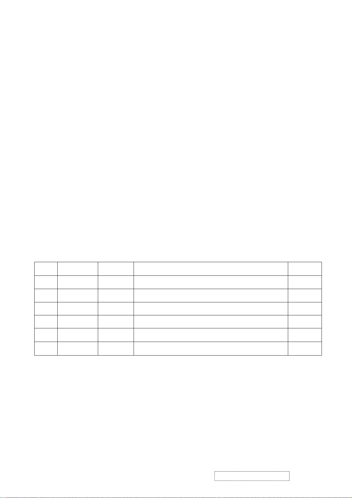
ECR Number
1a
1b
06/06/05
06/23/06
VS-E060083
Revision History
Description of Changes
Initial Release
updated RSPL,BOM,EPL,PPL
EditorRevision SM Editing Date
A. Lu
Jamie C.
ViewSonic Corporation Confidential
i
-
Do Not Copy
VX724-1
TABLE OF CONTENTS
1. Precautions and Safety Notices 1
2. Specification 5
3. Front Panel Function Control Description 17
4. Circuit Description 23
5. Adjustment Procedure 35
6. Troubleshooting Flow Chart 57
7. Recommended Spare Parts List 63
8. Exploded Diagram and Exploded Parts List 68
9. Block Diagram 79
10. Schematic Diagrams 81
11. PCB Layout Diagrams 89
ViewSonic Corporation Confidential
ii
-
Do Not Copy
VX724-1

1. Precautions and Safety Notices
1. Appropriate Operation
(1) Turn off the product before cleaning.
(2) Use only a dry soft cloth when cleaning the LCD panel surface.
(3) Use a soft cloth soaked with mild detergent to clean the display housing.
(4) Use only a high quality, safety approved AC/DC power cord.
(5) Disconnect the power plug from the AC outlet if the product will not be used for a long period of time.
(6) If smoke, abnormal noise, or strange odor is present, immediately switch the LCD display off.
(7) Do not touch the LCD panel surface with sharp or hard objects.
(8) Do not place heavy objects on the LCD display, video cable, or power cord.
(9) Do not use abrasive cleaners, waxes or solvents for your cleaning.
(10) Do not operate the product under the following conditions:
- Extremely hot, cold or humid environment.
- Areas containing excessive dust and dirt.
- Near any appliance generating a strong magnetic field.
- In direct sunlight.
2. Caution
No modification of any circuit should be attempted. Service work should only be performed after you are thoroughly familiar
with all of the following safety checks and servicing guidelines.
3. Safety Check
Care should be taken while servicing this LCD display. Because of the high voltage used in the inverter circuit, the voltage is
exposed in such areas as the associated transformer circuits.
4. LCD Module Handling Precautions
4.1 Handling Precautions
(1) Since front polarizer is easily damaged, pay attention not to scratch it.
(2) Be sure to turn off power supply when connecting or disconnecting input connector.
(3) Wipe off water drops immediately. Long contact with water may cause discoloration or spots.
(4) When the panel surface is soiled, wipe it with absorbent cotton or other soft cloth.
(5) Since the panel is made of glass, it may break or crack if dropped or bumped on hard surface.
(6) Since CMOS LSI is used in this module, take care of static electricity and ensure human earth when handling.
(7) Do not open or modify the Module Assembly.
(8) Do not press the reflector sheet at the back of the module in any direction.
(9) In the event that a Module must be put back into the packing container slot after it was taken out of the
container, do not press the center of the CCFL Reflector edge. Instead, press at the far ends of the
CFL Reflector edge softly. Otherwise the TFT Module may be damaged.
(10) At the insertion or removal of the Signal Interface Connector, be sure not to rotate or tilt the Interface
Connector of the TFT Module.
ViewSonic Corporation Confidential
1
-
Do Not Copy VX724-1

(11) After installation of the TFT Module into an enclosure (LCD monitor housing, for example), do not twist or
bend the TFT Module even momentarily. When designing the enclosure, it should be taken into consideration
that no bending/twisting forces may be applied to the TFT Module from outside. Otherwise the TFT Module
may be damaged.
(12) The cold cathode fluorescent lamp in the LCD contains a small amount of mercury. Please follow local
ordinances or regulations for disposal.
(13) The LCD module contains a small amount of materials having no flammability grade. The LCD module
should be supplied with power that complies with the requirements of Limited Power Source
(IEC60950 or UL1950), or an exemption should be applied for.
(14) The LCD module is designed so that the CCFL in it is supplied by a Limited Current Circuit (IEC60950
or UL1950). Do not connect the CCFL to a Hazardous Voltage Circuit.
ViewSonic Corporation Confidential
2
-
Do Not Copy VX724-1

Correct methods : Incorrect Methods :
Only touch the metal frame of the panel or the front
cover of the monitor.
Do not touch the surface of the polarizer .
If the surface of the panel is pressed by fingers, this
may cause "MURA."
Take out the monitor by grasping the cushion. If the monitor is removed by grasping the LCD
panel, that may cause "MURA."
ViewSonic Corporation Confidential
3
-
Do Not Copy VX724-1

Correct Methods : Incorrect Methods :
Place the monitor on a clean & soft foam pad . If the monitor is placed on foreign objects,
that could scratch the surface of the panel.
ViewSonic Corporation Confidential
4
-
Do Not Copy VX724-1
2. Specification
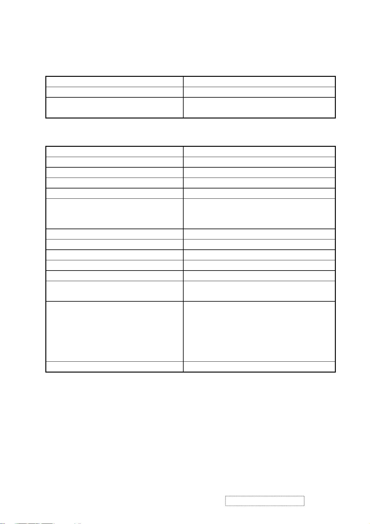
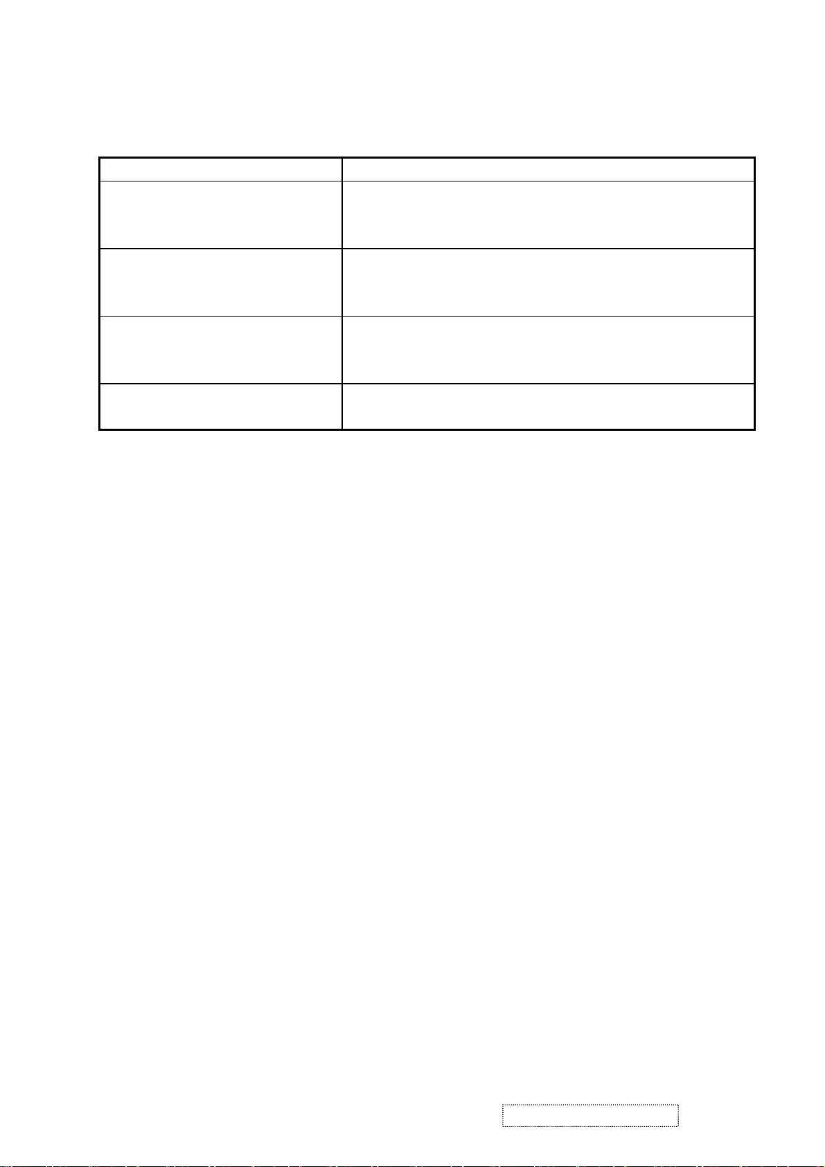
GENERAL SPECIFICATION
Test Resolution & Frequency 1280x1024 @ 60Hz
Test Image Size Full Size
Contrast and Brightness Controls
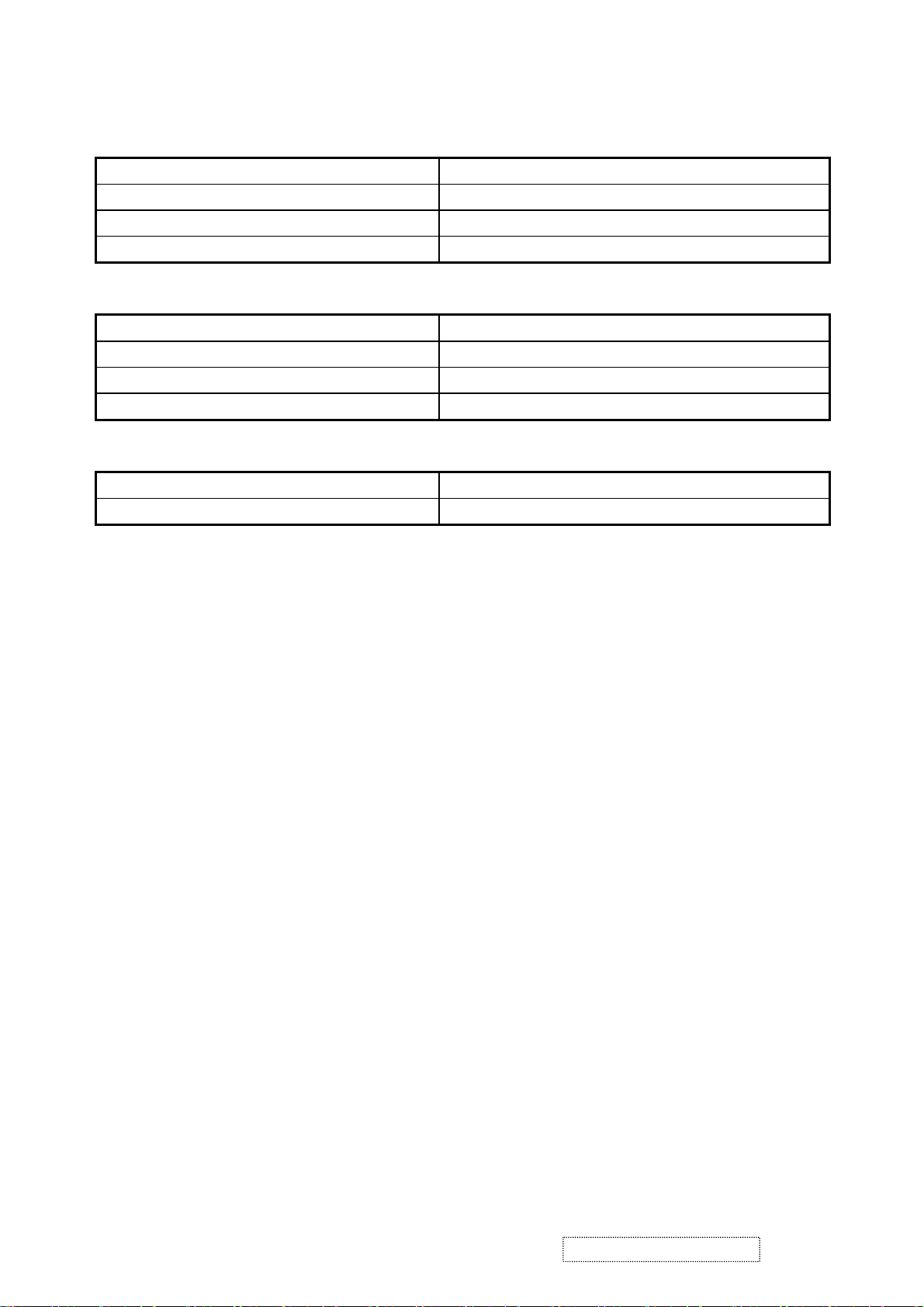
VIDEO INTERFACE
Analog Input Connector DB-15 (Analog), refer the appendix A
Digital Input Connector DVI-I (Digital), refer the appendix B
Default Input Connector Defaults to the first detected input
Video Cable Strain Relief Equal to twice the weight of the monitor for five minutes
Video Cable Connector DB-15 Pin out Compliant DDC 2B
Video Signals
Video Impedance 75 Ohms (Analog), 100 Ohms (Digital)
Maximum PC Video Signal 950 mV with no damage to monitor
Maximum Mac Video Signal 1250 mV with no damage to monitor
DDC 1/2B Compliant with Revision 1.3
Sync Compatibility Separate Sync, Composite Sync, SOG
Video Compatibility
Resolution Compatibility
Exclusions Not compatible with interlaced video
Factory Default:
Contrast = 70%, Brightness = 100%
1. Video RGB (Analog)
Separate, Composite, and Sync on Green
2. TMDS (Digital)
Shall be compatible with all PC type computers,
Macintosh computers, and after market video cards
640 x 350*, 640 x 480, 720 x 400* (640 x 400*), 800 x
600, 832 x 624, 1024 x 768, 1152 x 864, 1152 x 870,
1280 x 720, 1280 x 1024
* The image vertical size might not be full screen, but
the image vertical position should be at the center.
ViewSonic Corporation Confidential
5
-
Do Not Copy VX724-1
POWER SUPPLY
Internal Power Supply Part Number: FSP035-1PI01
Input Voltage Range 90 TO 264 VAC
Input Frequency Range 47.5 TO 63 HERTZ
Short Circuit Protection Output can be shorted without damage
Over Current Protection 5.0 A typical at 12.0 VDC
Leakage Current 3.5mA (Max) at 254VAC / 60Hz
EFFICIENCY 65 % typical at 115VAC Full Load
Fuse Internal and not user replaceable
Power Dissipation 32 Watts (typ)
Max Input AC Current 1.0 Arms @ 90VAC, 0.6 Arms @265VAC
INRUSH CURRENT (COLD START) 60 A @ 120VAC
Shall start and function properly when under full load,
Power Supply Cold Start
with all combinations of input voltage, input frequency,
and operating temperature
Shall be able to withstand an ANSI/IEEE C62.41-1980
Power Supply Transient Immunity
6000V 200 ampere ring wave transient test with no
damage
Power Supply Line Surge Immunity
Shall be able to withstand 1.5 times nominal line voltage
for one cycle with no damage
Shall be able to function properly, without reset or visible
Power Supply Missing Cycle Immunity
screen artifacts, when ½ cycle of AC power is randomly
missing at nominal input
The power supply shall not produce audible noise that
would be detectable by the user. Audible shall defined
Power Supply Acoustics
to be in compliance with ISO 7779 (DIN EN27779:1991)
Noise measurements of machines acoustics. Power
Switch noise shall not be considered
Separate 3-prong NEMA 5-15P type plug. Length =
US Type Power Cable
1.8m. Connects to display.
Color = Black
Schuko CEE7-7 type plug.
European Type Power Cable
Length = 1.8m, Connects to display.
Color = Black
Separate 3-prong type plug.
CCC Type Power Cable
Length = 1.8m. Connects to display.
Color = Black
Separate 2-prong NEMA 1-15P type plug. Length =
PSE Type Power Cable
1.8m. Connects to display.
Color = Black
Power Saving Operation(Method) VESA DPMS Signaling
Power Consumption
ON Mode < 35 W (max) / 32 W (typ)
Active Off < 1 W
Recovery Time On Mode = N/A, Active Off < 3 sec
ViewSonic Corporation Confidential
6
-
Do Not Copy VX724-1
ELECTRICAL REQUIREMENT
Horizontal / Vertical Frequency
Horizontal Frequency 30 – 82 KHZ
Vertical Refresh Rate 50 – 75 HZ
Maximum Pixel Clock 135 MHz
Sync Polarity Independent of sync polarity.
Timing Table
Item Timing Analog Digital
1 640 x 350 @ 70Hz, 31.5kHz Yes Yes
2 640 x 400 @ 60Hz, 31.5kHz Yes Yes
3 640 x 400 @ 70Hz, 31.5kHz Yes Yes
4 640 x 480 @ 50Hz, 24.7kHz Yes No
5 640 x 480 @ 60Hz, 31.5kHz Yes Yes
6 640 x 480 @ 67Hz, 35.0kHz Yes Yes
7 640 x 480 @ 72Hz, 37.9kHz Yes Yes
8 640 x 480 @ 75Hz, 37.5kHz Yes Yes
9 640 x 480 @ 85Hz, 43.27kHz No No
10 720 x 400 @ 70Hz, 31.5kHz Yes Yes
11 800 x 600 @ 56Hz, 35.1kHz Yes Yes
12 800 x 600 @ 60Hz, 37.9kHz Yes Yes
13 800 x 600 @ 75Hz, 46.9kHz Yes Yes
14 800 x 600 @ 72Hz, 48.1kHz Yes Yes
15 800 x 600 @ 85Hz, 53.7kHz No No
16 832 x 624 @ 75Hz, 49.7kHz Yes Yes
17 1024 x 768 @ 60Hz, 48.4kHz Yes Yes
18 1024 x 768 @ 70Hz, 56.5kHz Yes Yes
19 1024 x 768 @ 72Hz, 58.1kHz Yes Yes
20 1024 x 768 @ 75Hz, 60.0kHz Yes Yes
21 1024 x 768 @ 85Hz, 68.67kHz No No
22 1152 x 864 @ 75Hz, 67.5kHz Yes Yes
23 1152 x 870 @ 75Hz, 68.7kHz Yes Yes
24 1280 x 1024 @ 60Hz, 63.4kHz Yes Yes
25 1280 x 1024 @ 75Hz, 79.97kHz Yes Yes
26 1280x 720 @ 60Hz, 45kHz (HDTV) Yes Yes
ViewSonic Corporation Confidential
7
-
Do Not Copy VX724-1

Primary Presets
1280x1024 @ 60Hz
User Presets
Number of User Presets (recognized timings) Available: 10 presets total in FIFO configuration
Changing Modes
- Maximum Mode Change Blank Time for image stability : 3 seconds (Max), excluding “Auto Image Adjust” time
- Under DOS mode (640 x 350, 720 x 400 & 640 x 400), it should recall factory setting when execute “Auto I
mage Adjust”
- The monitor needs to do “Auto Image Adjust” the first time a new mode is detected
(see section “0-Touch™ Function Actions”)
ViewSonic Corporation Confidential
8
-
Do Not Copy VX724-1
TFT LCD PANEL
Panel Characteristics:
1st Source Panel
AUO M170EG01 V8
Type TN type with LVDS interface
Active Size 337.9 (H) x 270.3 (V)
Pixel Arrangement RGB Vertical Stripe
Pixel Pitch 0.264 mm
GLASS TREATMENT Anti Glare (Hard coating 3H)
# OF BACKLIGHTS 4 CCFL edge-light (2 top / 2 bottom)
BACKLIGHT LIFE 50,000 Hours (Typ) / 40,000 Hours (Min)
Luminance –
Condition:
300 cd/m2 (Typ after 30 minute warm up)
240 cd/m2 (Min after 30 minute warm up)
CT = 6500K, Contrast = Max, Brightness =
Max
Brightness Uniformity 80% (typ), 75% (min)
MIN LUMINANCE IN 9 POINTS/ MAX
LUMINANCE IN 9 POINTS
Contrast Ratio 500:1 (Typ), 300:1 (Min)
Color Depth 16 million colors (x bit panel)
Viewing Angle (Horizontal) @ CR>10
Typical: 140º
MINIMUM: 120º
VIEWING ANGLE (VERTICAL) @ CR>10
Typical: 130º
Minimum: 110º
@ CR>5
Typical: 160º
M INIMUM: 140º
@ CR>5
Typical: 160º
Minimum: 140º
Without OD Board (on/off)
Tr = 6ms,Tf = 2ms Total = 8ms (typ)
Tr = 9ms,Tf = 4ms Total = 13ms (max)
Response Time
With OD Board (on/ off)
10%-90% @ Ta=25°C
Tr = 3.9ms,Tf = 1.5ms Total = 5.4ms (typ)
With OD Board (gray –gray)
Total = 4 ms
Panel Defects Please see Panel Quality Specifications.
ViewSonic Corporation Confidential
9
-
Do Not Copy
VX724-1

2ND Source Panel
QDI QD17EL0709
Type TN type with LVDS interface
Active Size 337.9 (H) x 270.3 (V)
Pixel Arrangement RGB Vertical Stripe
Pixel Pitch 0.264 mm
GLASS TREATMENT Anti Glare (Hard coating 3H)
# OF BACKLIGHTS 4 CCFL edge-light (2 top / 2 bottom)
BACKLIGHT LIFE 50,000 Hours (Typ) / 40,000 Hours (Min)
Luminance (Center) –
Condition:
260 cd/m2 (Typ after 30 minute warm up)
200 cd/m2 (Min after 30 minute warm up)
CT = 6500K, Contrast = Max, Brightness =
Max
Brightness Uniformity Dw = 1.25 (typ), 1.33 (max)
dw = Max luminance (of 9 points)/ Min
luminance (of 9 points)
Contrast Ratio 500:1 (typ), 300:1 (min)
Color Depth 16.2 million colors (6+2 bit panel)
Viewing Angle (Horizontal) @ CR>10
Typical: 140º
Minimum: 120º
VIEWING ANGLE (VERTICAL) @ CR>10
Typical: 125º
Minimum: 105º
@ CR>5
Typical: 160º
Minimum: 140º
@ CR>5
Typical: 145º
Minimum: 125º
Without OD Board (on/off)
Tr = 2ms,Tf = 6ms Total = 8ms (typ)
Total =13ms(max)
Response Time
With OD Board (on/ off)
10%-90% @ Ta=25°C
Tr = 1.4ms,Tf = 5.3ms Total = 6.7ms (typ)
With OD Board (gray –gray)
Total = 4 ms
Panel Defects Please see Panel Quality Specifications.
ViewSonic Corporation Confidential
10
-
Do Not Copy VX724-1

3rd Source Panel
QDI QD17EL0711
Type TN type with LVDS interface
Active Size 337.9 (H) x 270.3 (V)
Pixel Arrangement RGB Vertical Stripe
Pixel Pitch 0.264 mm
GLASS TREATMENT Anti Glare (Hard coating 3H)
# OF BACKLIGHTS 4 CCFL edge-light (2 top / 2 bottom)
BACKLIGHT LIFE 50,000 Hours (Typ) / 40,000 Hours (Min)
Luminance (Center) –
Condition:
270 cd/m2 (Typ after 30 minute warm up)
220 cd/m2 (Min after 30 minute warm up)
CT = 6500K, Contrast = Max, Brightness =
Max
Brightness Uniformity Dw = 1.25 (typ), 1.33 (max)
dw = Max luminance (of 9 points)/ Min
luminance (of 9 points)
Contrast Ratio 600:1 (typ), 400:1 (min)
Color Depth 16.2 million colors (6+2 bit panel)
Viewing Angle (Horizontal) @ CR>10
Typical: 140º
Minimum: 120º
VIEWING ANGLE (VERTICAL) @ CR>10
Typical: 125º
Minimum: 105º
@ CR>5
Typical: 160º
Minimum: 140º
@ CR>5
Typical: 145º
Minimum: 125º
Without OD Board (on/off)
Tr = 2ms,Tf = 6ms Total = 8ms (typ)
Total =13ms(max)
Response Time
With OD Board (on/ off)
10%-90% @ Ta=25°C
Tr = 1.4ms,Tf = 5.3ms Total = 6.7ms (typ)
With OD Board (gray –gray)
Total = 4 ms
Panel Defects Please see Panel Quality Specifications.
ViewSonic Corporation Confidential
11
-
Do Not Copy VX724-1
IMAGE PERFORMANCE
Factory Defaults
Item Defaults Item Defaults
Contrast 70% OSD H. Position 50%
Brightness 100% OSD V. Position 50%
Color Temperature 6500K OSD Time Out 15 Sec
Sharpness 25% OSD Background On
720x400/640x400 720x400 Resolution Notice Enabled
Luminance
Lv (Max) –
Condition:
Same as the Luminance in section
4-7 “TFT LCD PANEL”
Contrast = 100%
Brightness = 100%
Color Temperature = 6500K
Lv (Def) –
Condition:
Contrast = Default
Lv (Def) / Lv (Max) x 100% ≧ 85%
Brightness = Default
Color Temperature = 6500K
Display Size
Horizontal Display Size, Primary Preset Full Screen
Vertical Display Size, Primary Preset Full Screen
Saturation
Contrast = Default
Brightness = Default
No visible saturation
TEST PATTERN = 32-GRAY
Contrast = 100%
Brightness = 100%
6~8 level saturation
Test pattern = 32-gray
ViewSonic Corporation Confidential
12
-
Do Not Copy VX724-1
Preset Color Temperatures
SRGB It should meet IEC 61966-2-1 (1999-10) standard
Preset 1 9300K
CCT (Max) = 10250K
CCT (Min) = 8500K
Preset 2 6500K (Primary)
CCT (Max) = 6950K
CCT (Min) = 6100K
Preset 3 5400K
CCT (Max) = 5915K
CCT (Min) = 4935K
Preset Color Temperature
Adjustability
Wx= 0.283 +/- 0.02
Wy= 0.298 +/- 0.02
Wx= 0.313 +/- 0.02
Wy= 0.329 +/- 0.02
Wx= 0.335 +/- 0.02
Wy= 0.350 +/- 0.02
Each color preset shall be adjustable. Red, Green, and Blue shall be
individually controlled.
Video Cards Compatibility
Peaking Performance : Peaking is not adjustable
Raster Artifacts
- Video Artifacts : No visible streaking, sag, or smearing artifacts when driven by the specified video cards in the
primary mode and after user adjustment to best condition
- Power Supply, and Grounding Artifacts : No visible artifacts in any specified video mode within the horizontal or
vertical frequency range of the monitor
- Temperature Drift : Image shall not drift or lose fine-tune adjustment
ViewSonic Corporation Confidential
13
-
Do Not Copy VX724-1
MECHANICAL
Dimension (Desktop)
Width 388 mm (15.3 inch)
Height 438 mm (17.2 inch)
Depth 176 mm ( 6.9 inch)
Monitor Weight 5 kg / 11 lbs
Dimension (Head Only / Wall Mount)
Width 388 mm (15.3 inch)
Height 332 mm (13.1 inch)
Depth 62 mm (2.4 inch)
Monitor Weight 3.5 kg / 7.7 lbs
Ergonomics
Tilt Up From 0º up to ≧20º
Tilt Down From 0º down to -3º ~ -5 º
Mechanical Specifications
- Screen Printed Parts : Artwork shall be provided by ViewSonic. The ViewSonic Bezel Graphics Specification,
VSC_S_299 v.1d (2003) controls logo position
- Bird Logo : The ViewSonic Bird Logo Plate Specification, VSC_S_286 v.1b controls bird logo position
- Molded Plastic : Workmanship shall be inspected according to the ViewSonic Molded Plastic Parts Specification,
VSCMPPSPEC001 v.1b
- Head Tilt Specification : In order to control the visible tilt of the LCD head, all units must have less than 1.5mm
difference in height between the lower center and left / right corner of the bezel
- Bezel Gap Specification: The max. gap to the panel glass shall be less than 1.0 mm
- Bezel / Speaker Cover Gap : The max. gap between the bottom of the front bezel and the top of the speaker cover
shall be less than 1.2 mm. The gap deviation must be less than 0.3mm
- External Jumpers : There shall be no external jumpers allowed
- Panel Preload Pressure :The LCD panel shall not experience any preload pressure when mounted to the bezel
causing image degradation
- Front Panel Buttons : Tactile
- Button Alignment : The gap clearance between the buttons and the bezel surface shall be uniform
- Cold Cathode Fluorescent Tubes (CCFT) Cables : Cables between inverter and CCFT shall not have any direct
contact to any cabinet surface or opening exposing users to the risk of electric shock. CCFT cables shall be
properly routed internally to prevent them from straying to other areas within the monitor
- Sheet Metal Parts : All sharp edges of sheet metal parts that have the possibility of coming into contact with wire
harnesses, flexible flat cables (FFCs), CCFT cables shall be covered with felt tape to protect the cable’s insulation
from being damaged. If felt tape is not used, then the edges of the sheet metal shall be machined smooth to prevent
wiring insulator damage
ViewSonic Corporation Confidential
14
-
Do Not Copy VX724-1

Tilt/Swivel Base Mechanical Interface
The LCD monitor shall be in compliance with the most current revision of the VESA “Flat Panel Monitor Physical
Mounting Interface” Standard, “FPMPMI Standard”
PACKAGING
Package Specifications
ViewSonic Packaging Specification The “Top Level Assembly” shall meet the ViewSonic Corporation
Packaging Specification, VSCPACSPEC003
Ink The ink shall not rub off after a suitable drying time.
Multiple Trips
The carton shall withstand 10 trips by any combination of air, rail,
land, or sea transportation.
Shipping Carton Type One piece construction with double wall, 1.08 Kg
Shipping Carton Handholds Yes, on side of carton
Poly form EPS, 210g
Accessory plastic bags PE-LD, 3 g
Plastic handle PE-plastic, 20g (on the top side of carton)
PE bag (covers monitor) PE-LD, 5 g
Width / Height / Depth 456mm (17.9”) / 529mm (20.8”) / 227mm (8.9”)
Gross Weight 7 kg (15.4 lb)
Pallet (for Europe) Poplar, 21 Kg
Pallet (for others) Fumigation wood, 21 Kg
# units per Pallet 20/40 (air/sea)
40’ Container Loading, Palletized 1040 pieces
ViewSonic Corporation Confidential
15
-
Do Not Copy VX724-1

Vibration Test
- Vibration Frequency : 1 – 200 Hz
- Acceleration : 1.14 G RMS
- Sweep Time : 1 oct. / min
- Test Time : 60 min per axis, total 3 axis / 6 main face
-Vibration Test Data shall be submitted for approval to ViewSonic before Mass Production
Drop Test (100G)
- Weak Corner : 76.2 cm
- Six Faces : 76.2 cm
- 3 Edges Radiating From Weak Corner : 76.2 cm
- Drop Test Data shall be submitted for approval to ViewSonic before Mass Production
ENVIRONMENTAL
- Operating Temperature : 0°C to +40°C
- Storage Temperature : -20°C to +60°C
- Operating Relative Humidity : 20% to 90% RH Non-Condensing
- Storage Relative Humidity : 5% to 90% RH Non-Condensing
- Operating Altitude : 0 to +3,000 meters
-Storage Altitude : 0 to +12,000 meters
ViewSonic Corporation Confidential
16
-
Do Not Copy VX724-1
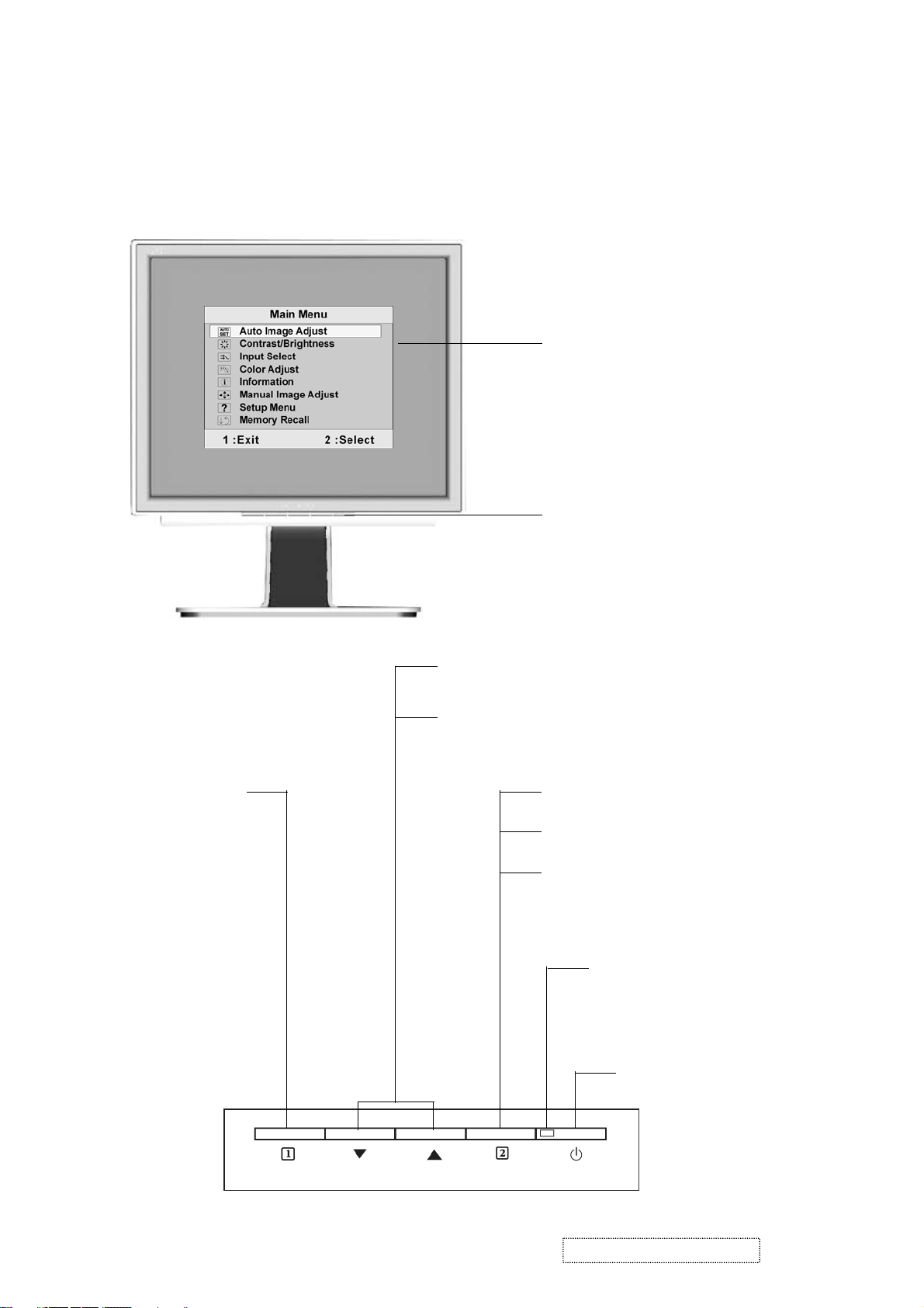
3. Front Panel Function Control Description
Adjusting the Screen Image
Use the buttons on the front control panel to display and adjust the OSD controls which display
on the screen. The OSD controls are explained at the top of the next page and are defined in
“Main Menu Controls” on page 17.
Main Menu
with OSD controls
Front Control Panel
shown below in detail
Displays the Main
Menu or exits the
control screen
and saves
adjustments.
Scrolls through menu options and adjusts the
displayed control.
Also a shortcut to display the Contrast adjustment
control screen.
Displays the control screen for the
highlighted control.
Also toggles between two controls on
some screens.
Also a shortcut to toggle analog and
digital connection.
Power light
Green = ON
Orange = Power Saving
Power On/Off
ViewSonic Corporation Confidential
17
-
Do Not Copy VX724-1
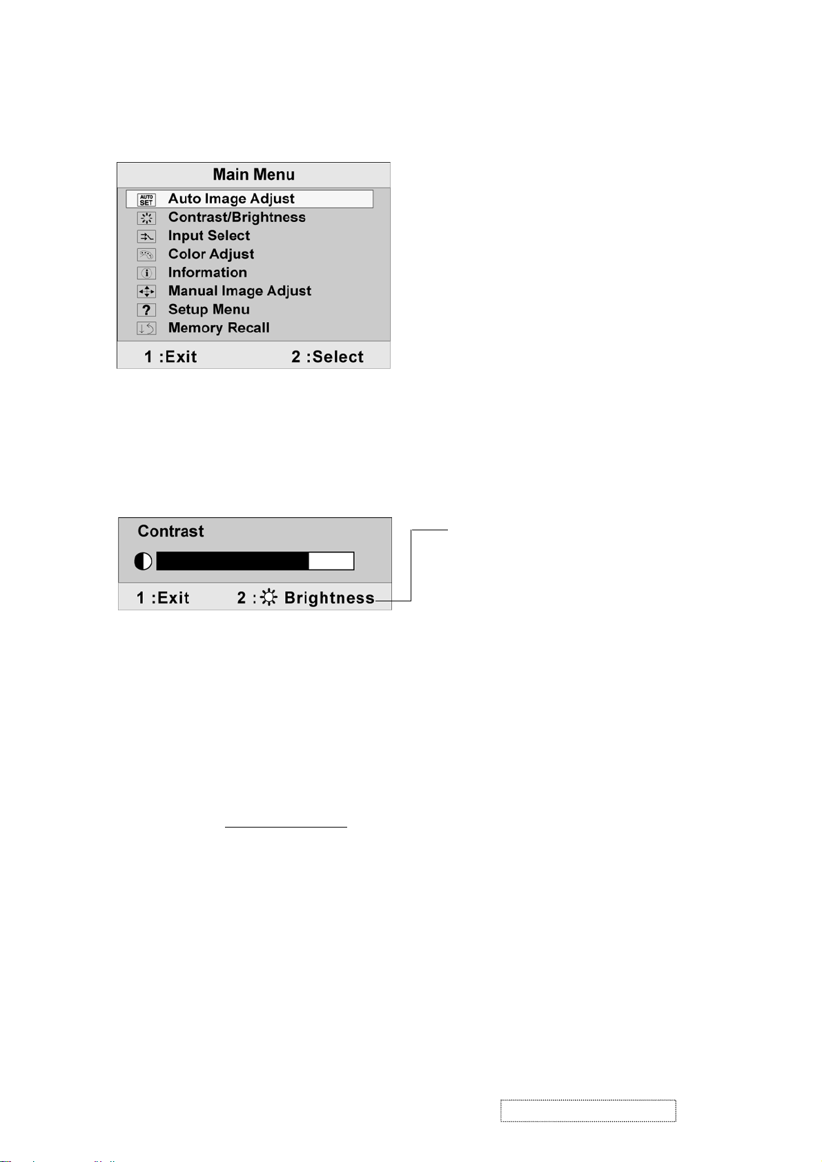
Do the following to adjust the display setting:
1. To display the Main Menu, press button [1].
NOTE: All OSD menus and adjustment screens disappear automatically after about 30
seconds. This is adjustable through the OSD timeout setting in the setup menu.
2. To select a control to adjust, pressSorTto scroll up or down in the Main Menu.
3. After the desired control is selected, press button [2]. A control screen like the one shown
below appears.
The line at the bottom of the screen shows
the current functions of buttons 1 and 2:
Exit or select the Brightness control.
4. To adjust the setting, press the upSor downTbuttons.
5. To save the adjustments and exit the menu, press button [1] twice.
The following tips may help you optimize your display:
• Adjust the computer's graphics card so that it outputs a 1280 x 1024 @ 60Hz video signal to
the LCD display. (Look for instructions on “changing the refresh rate” in the graphics card's
user guide.)
• If necessary, make small adjustments using H. POSITION and V. POSITION until the
screen image is completely visible. (The black border around the edge of the screen should
barely touch the illuminated “active area” of the LCD display.)
ViewSonic Corporation Confidential
18
-
Do Not Copy VX724-1
Main Menu Controls
Adjust the menu items shown below by using the upSand downTbuttons.
Control Explanation
Auto Image Adjust automatically sizes, centers, and fine tunes the video signal
to eliminate waviness and distortion. Press the [2] button to obtain a sharper
image.
NOTE:
1. Auto Image Adjust works with most common video cards. If this function
does not work on your LCD display, then lower the video refresh rate to 60
Hz and set the resolution to its pre-set value.
2. The Auto Image Adjust and most Manual Image Adjust functions are not
available for DVI input.
Contrast adjusts the difference between the image background (black level)
and the foreground (white level).
Brightness adjusts background black level of the screen image.
Input Select allows you to toggle between an analog and a digital signal.
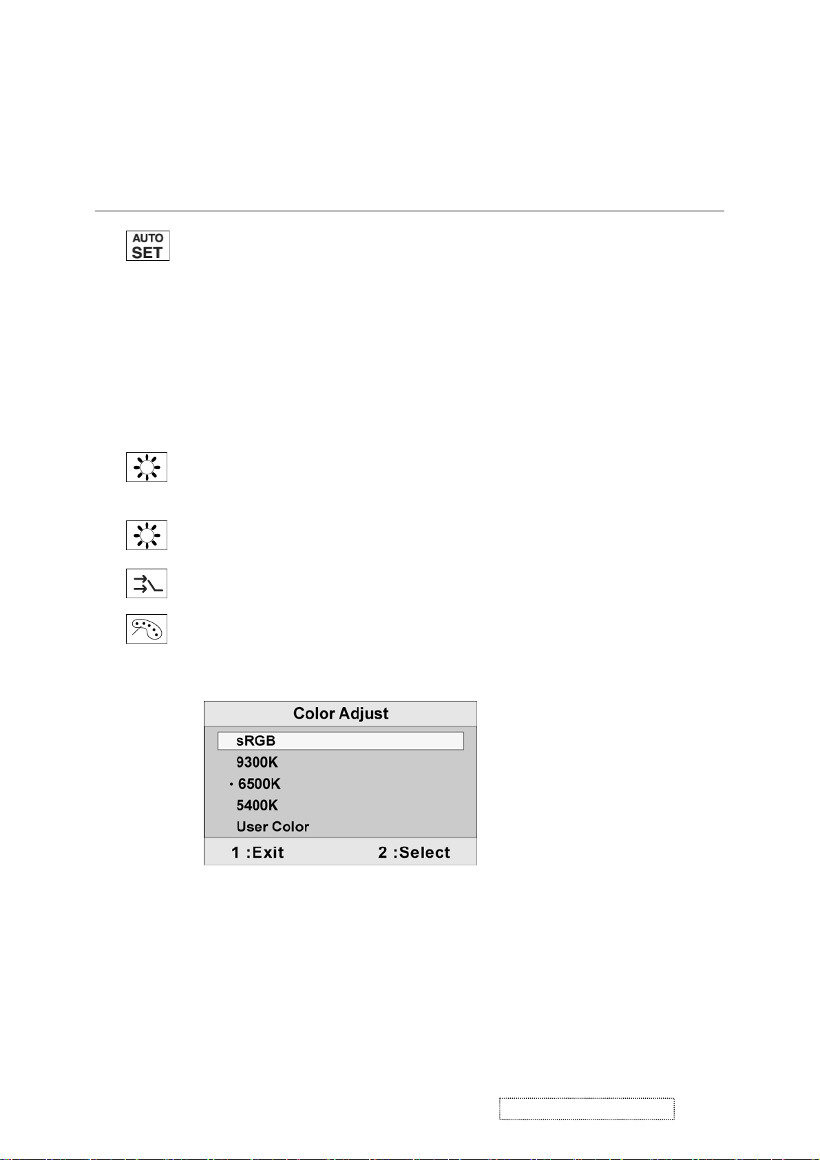
Color Adjust provides several color adjustment modes, including preset color
temperatures and a User Color mode which allows independent adjustment of
red (R), green (G), and blue (B). The factory setting for this product is 6500K
(6500 Kelvin).
sRGB-This is quickly becoming the industry standard for color management,
with support being included in many of the latest applications. Enabling this
setting allows the LCD display to more accurately display colors the way they
were originally intended. Enabling the sRGB setting will cause the Contrast and
Brightness adjustments to be disabled.
9300K-Adds blue to the screen image for cooler white (used in most office
settings with fluorescent lighting).
ViewSonic Corporation Confidential
19
-
Do Not Copy VX724-1
Control Explanation
6500K-Adds red to the screen image for warmer white and richer red.
5400K-Adds green to the screen image for a darker color.
User Color Individual adjustments for red (R), green (G), and blue (B).
1. To select color (R, G or B) press button [2].
2. To adjust selected color, pressSorT.
Important: If you select RECALL from the Main Menu when the product is set
to a Preset Timing Mode, colors return to the 6500K factory preset.
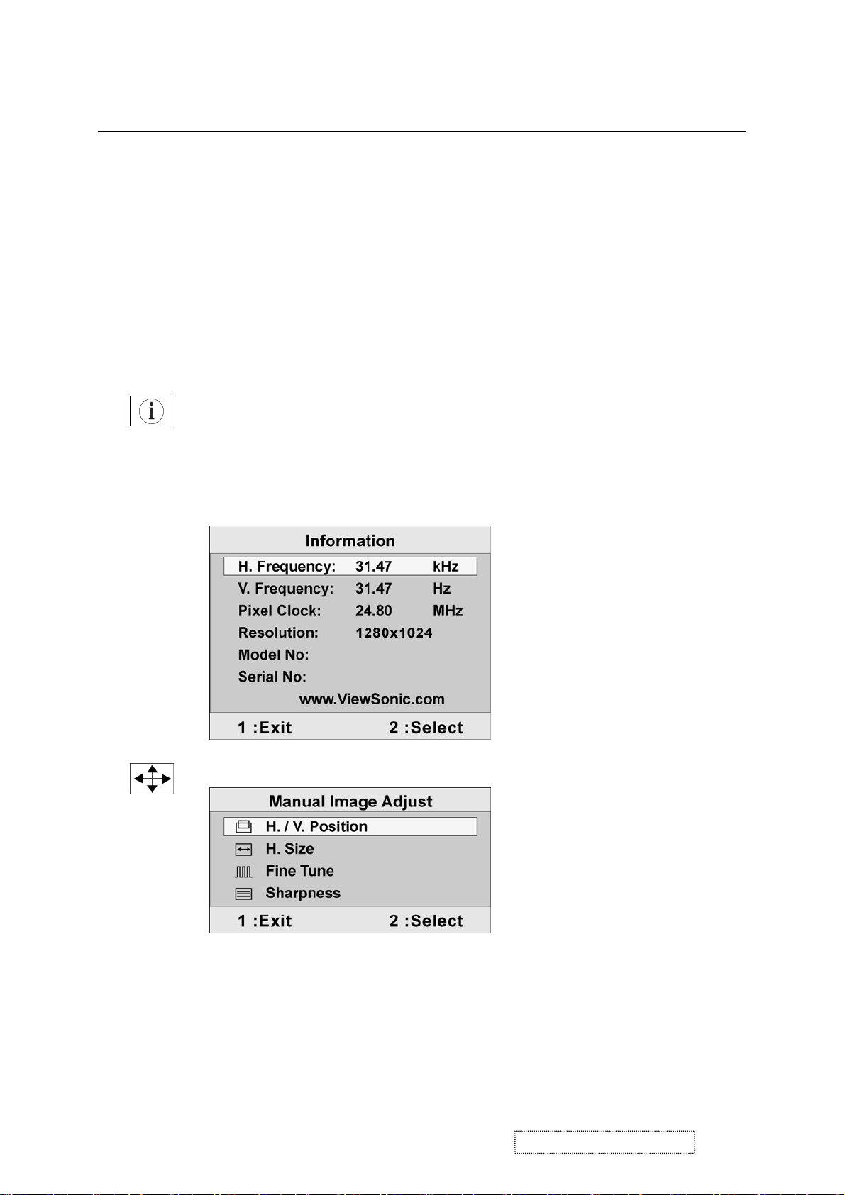
Information displays the timing mode (video signal input) coming from the
graphics card in the computer, the LCD model number, the serial number, and
the ViewSonic® website URL. See your graphics card’s user guide for
instructions on changing the resolution and refresh rate (vertical frequency).
NOTE: VESA 1280 x 1024 @ 60Hz (recommended) means that the resolution
is 1280 x 1024 and the refresh rate is 60 Hertz.
Manual Image Adjust displays the Manual Image Adjust menu.
ViewSonic Corporation Confidential
20
-
Do Not Copy VX724-1

Control Explanation
The Manual Image Adjust controls are explained below:
H./V. Position (Horizontal/Vertical Position) moves the screen image left or
right and up or down.
H. Size (Horizontal Size) adjusts the width of the screen image.
Fine Tune sharpens the focus by aligning the text and/or graphic characters
with pixel boundaries.
Sharpness adjusts the clarity and focus of the screen image.
Setup menu displays the menu shown below:
The Setup Menu controls are explained below:
Language select allows the user to choose the language used in the menus and
control screens.
Resolution Notice displays the Resolution Notice menu shown below.
Resolution Notice advises the optimal resolution to use.
OSD Position allows the user to move the on-screen display menus and control
screens.
ViewSonic Corporation Confidential
21
-
Do Not Copy VX724-1

Control Explanation
OSD Timeout sets the length of time the on-screen display screen is displayed.
For example, with a “15 second” setting, if a control is not pushed within 15
seconds, the display screen disappears.
OSD Background allows the user to turn the On-Screen Display background
On or Off.
Memory Recall returns the adjustments back to factory settings if the display is
operating in a factory Preset Timing Mode listed in the Specifications of this
manual.
Exception: This control does not affect changes made with the User Color
control, Language or Power Lock setting.
ViewSonic Corporation Confidential
22
-
Do Not Copy VX724-1
4. Circuit Description
1. Outline
1.1 Buttons on the front panel: Power On/Off button, button 2 (ENTER / INPUT SELECT), up arrow
button, down arrow button, button 1 (MENU).
1.2
The D-sub 15-pin connector, DVI-I connector and AC-IN jack are located on the back side of the cabinet.
1.3 The OSD menu includes the following functions:
Auto Image Adjust (only active under analog input)
Contrast/Brightness
Audio Adjust
Color Adjust
Information
Manual Image Adjust
Setup Menu
Memory Recall
1.4
Contrast and Brightness can be directly controlled with the UP / DOWN buttons.
2. Connectors
AC Socket: CEE22 type connector
2.1
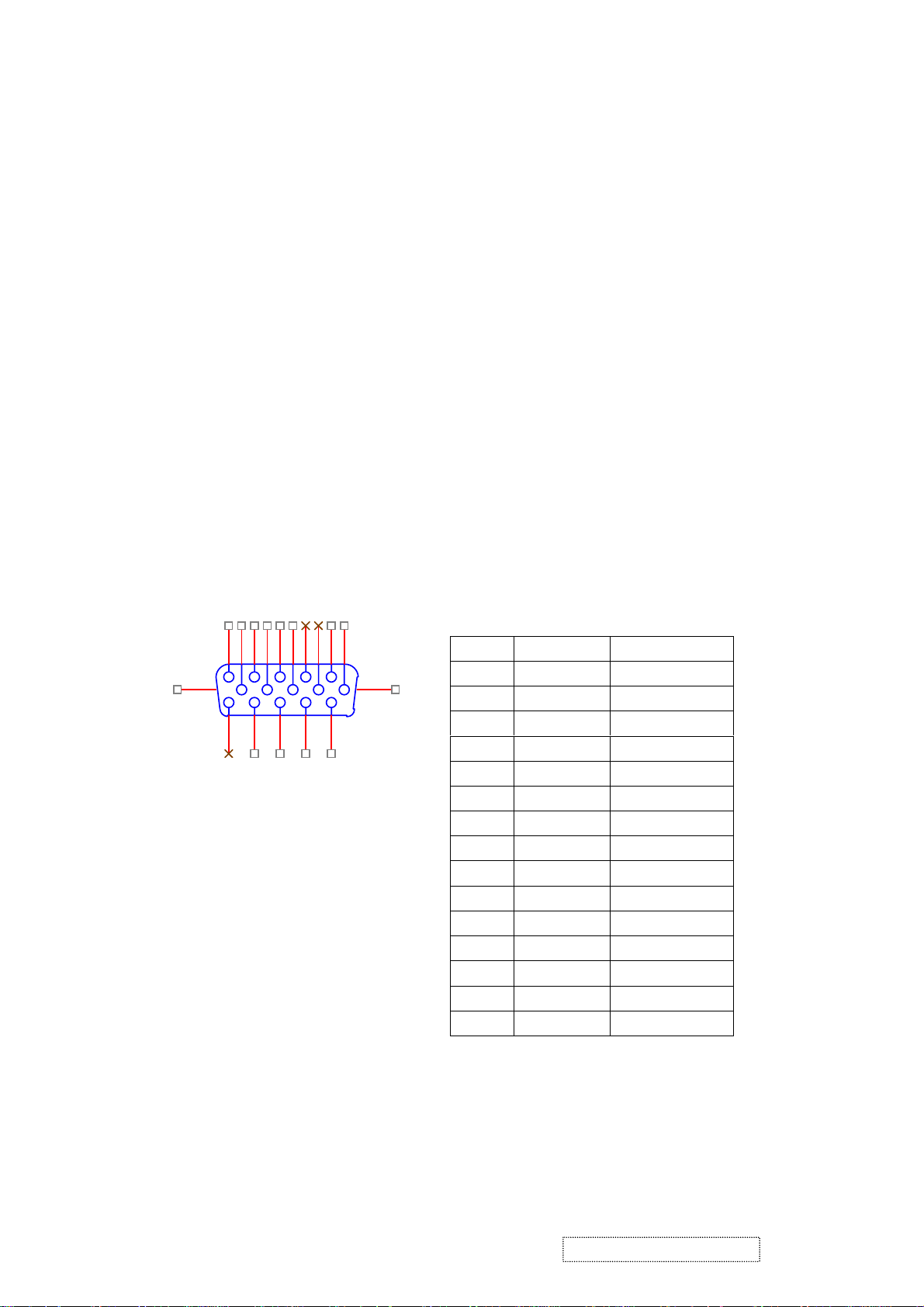
2.2 Video signal connector for analog input: 15P Mini D-Sub
16
1
11
6
2
7
3
8
4
9
12
13
14
5
15
10
CN6
DB15HD
17
PIN MNEMONIC SIGNAL
1 RV Red Video
2 GV Green Video
3 BV Blue Video
4 NC None
5 GND Ground(DDC return)
6 RG Red GND
7 GG Green GND
8 BG Blue GND
9 +5V +5V (for DDC)
10 SG Sync GND
11 NC None
12 SDA DDC Data
13 HS Horizontal Sync
14 VS Vertical Sync
15 SCL DDC Clock
ViewSonic Corporation Confidential
23
-
Do Not Copy
VX724-1
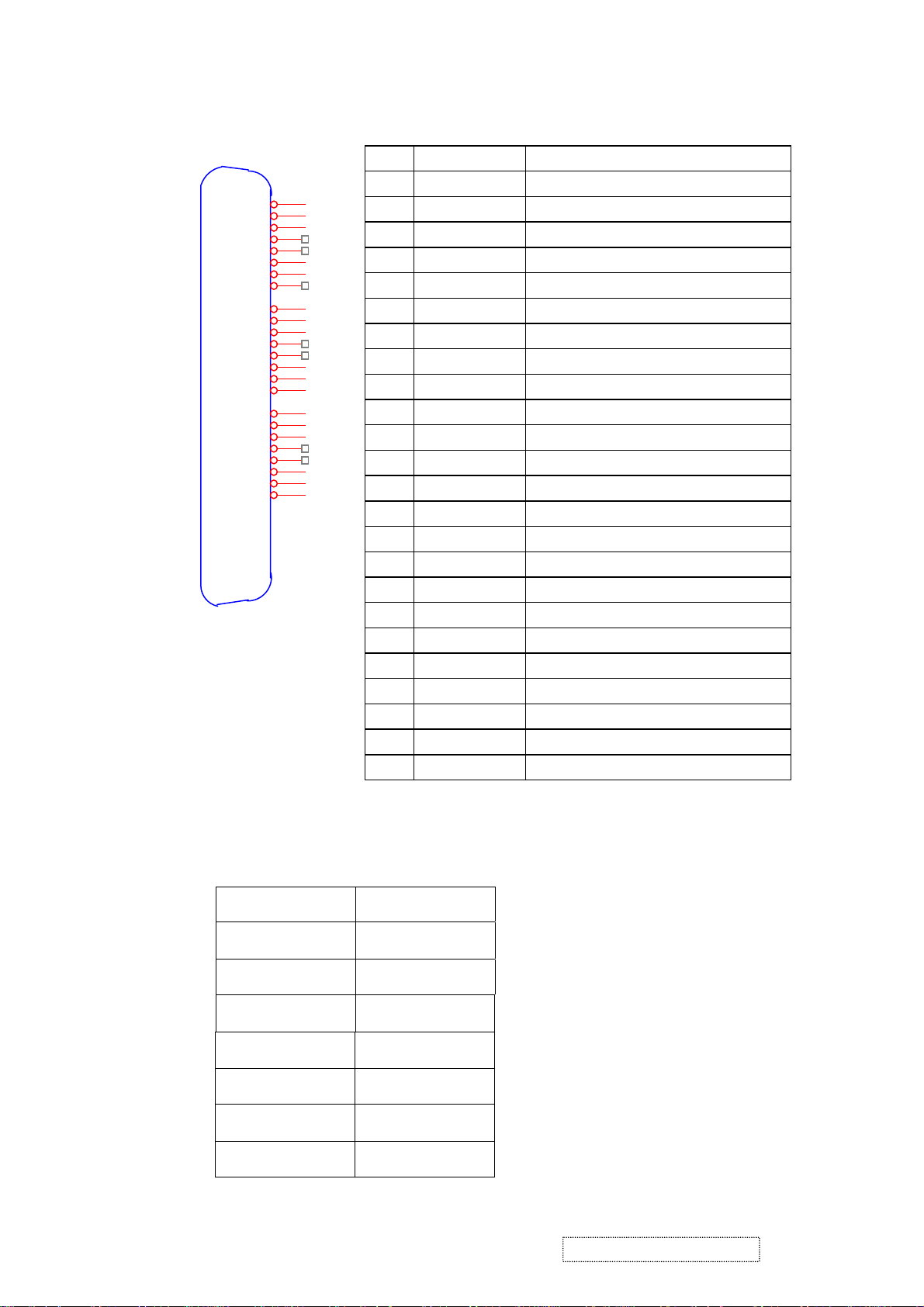
2.3
Video signal connector for digital input: 24pin DVI-D connector
CN9
1
RX2-
2
RX2+
3
GND
4
RX4-
5
RX4+
6
SCL
7
SDA
8
VS
9
RX1-
10
RX1+
11
GND
12
RX3-
13
RX3+
14
5V
15
GND
16
HP
17
RX0-
18
RX0+
19
GND
20
RX5-
21
RX5+
22
GND
23
RXC+
24
RXC-
3. Electrical Specifications
DVI-D
3.1 Standard conditions
Pin No. Signal Name Description
1 RX2- TMDS negative differential input, channel 2
2 RX2+ TMDS positive differential input, channel 2
3 GND Logic Ground
4 RX4- Reserved. No connection
5 RX4+ Reserved. No connection
6 SCL DDC2B Clock
7 SDA DDC2B Data
8 VS Reserved. No connection
9 RX1- TMDS negative differential input, channel 1
10 RX1+ TMDS positive differential input, channel 1
11 GND Logic Ground
12 RX3- Reserved. No connection
13 RX3+ Reserved. No connection
14 +5V Power
15 GND Logic Ground
16 HP SENSE Pin, Pull High
17 RX0- TMDS negative differential input, channel 0
18 RX0+ TMDS positive differential input, channel 0
19 GND Logic Ground
20 RX5- Reserved. No connection
21 RX5+ Reserved. No connection
22 GND Logic Ground
23 RXC+ TMDS positive differential input, reference clock
24 RXC- TMDS negative differential input, reference clock
Display Area
Video Signal
Contrast
Brightness
Ambient
Input
Warming up
Display
404.2 x 330.0 mm
0.7Vpp
Max.
Max.
20 +/- 5 °C
AC
> 30 min
1280 x 1024
ViewSonic Corporation Confidential
24
-
Do Not Copy
VX724-1

3.2 Power
3.2.1 Power supply
Input voltage 100~240Vac
Power frequency 50~60Hz
Input current
Inrush current
Power consumption 35W(typical);40Watts(Max)
3.2.2 Power Management
State Power Indicator
On 35Watts Green
Standby < 1Watts Amber
Off <1Watts Off
<1.5A RMS @90V AC
<0.8A RMS @180V AC
50A(Max) at 120Vac(cold start)
3.3 Acceptable timing
This LCD display can automatically detect and display input signals whose timing falls within the
following limits.
Horizontal: Sync frequency: 30~82 kHz
Vertical: Sync frequency: 56~75Hz
3.4 Signal level and input impedance
3.4.1 Video signal level: 0.7Vp-p
3.4.2 Sync signal level - H/V separate: TTL level
3.4.3 Input impedance
Analog video input: 75 ohm
Digital video input: 100 ohm
Sync input: > 1 k ohm
Audio input: 10K ohm
4. Signal Cable: Signal cable with Mini D-Sub 15P connectors at both ends. Length: 1.8 meter.
ViewSonic Corporation Confidential
25
-
Do Not Copy VX724-1
 Loading...