

Sony VTXD-800 Service manual
SERVICE MANUALSERVICE MANUAL
SERVICE MANUAL
SERVICE MANUALSERVICE MANUAL
Magellan IIMagellan II
Magellan II
Magellan IIMagellan II
CHASSISCHASSIS
CHASSIS
CHASSISCHASSIS
MODEL
VTX-D800UVTX-D800U
VTX-D800U
VTX-D800UVTX-D800U
VTX-D800NVTX-D800N
VTX-D800N
VTX-D800NVTX-D800N
VTX-D800EVTX-D800E
VTX-D800E
VTX-D800EVTX-D800E
COMMANDER DEST
RM-X800 UK
RM-X800 FINLAND/SWEDEN
RM-X800 ESP
DIGITAL RECEIVER
Service Manual
- 1 -

TABLE OF CONTENTS
Safety Warning. .................... 3
Tools Required. .................... 3
1 Dissassembly .................... 4
1.1 Cover Removal. .................... 4
1.2 Front Panel Removal. .................... 4
1.3 B Board Removal. .................... 5
1.4 Chassis Removal. .................... 5
2 Service Mode [TT Mode] .................... 6
2.1 Special Key Sequence .................... 6
2.2 Special Remote Commander Data Code .................... 6
2.3 Exiting TT Mode .................... 6
3 Entering the TT Command Number .................... 7
3.1 Cancelling a Command Entry .................... 7
3.2 Example .................... 7
4 List of TT Commands .................... 8
5 Power Supply .................... 11
5.1 Power Supply Detailed Description .................... 12
6 Technical Specifications . .................... 15
7 Device descriptions. .................... 19
8 Diagrams
8.1 Block Diagram. .................... 21
8.2 B board PWB layout. .................... 22
8.3 B board circuit diagram.
8.3.1 Multimedia Processor & Clock Generator .................... 23
8.3.2 Front Panel & Reset .................... 24
8.3.3 Power Supply .................... 25
8.3.4 Audio DAC & Smartlink Switch .................... 26
8.3.5 AV Switch & SCART .................... 27
8.3.6 Tuner NIM .................... 28
9 Exploded View . .................... 29
10 Electrical Parts List. .................... 30
Service Manual
- 2 -
Safety Warning
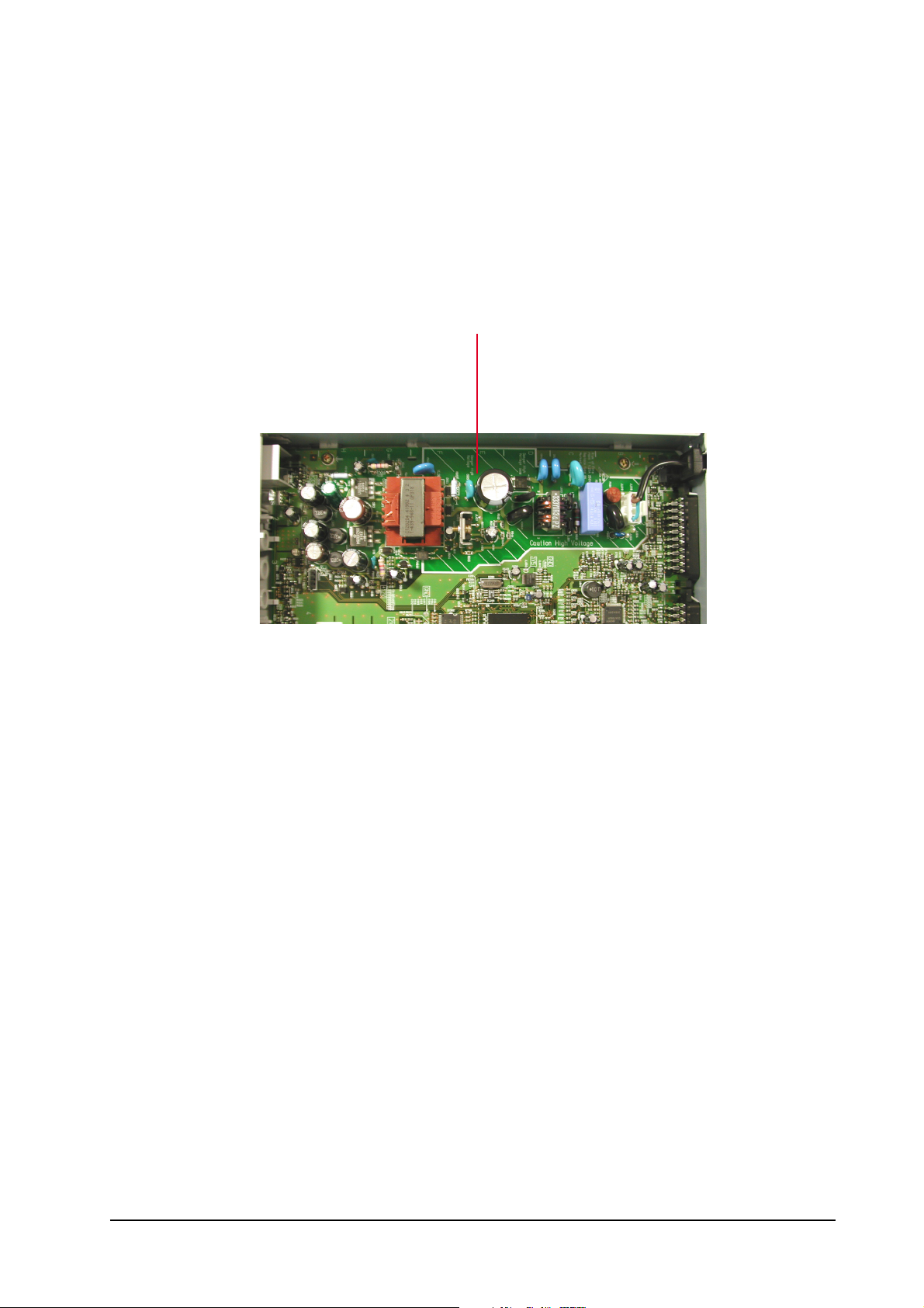
Dangerously high voltages exist on the Power Supply Unit (PSU) PWB (See Fig 1).
FOR THIS REASON, THE RECEIVER MUST ALWAYS BE DISCONNECTED FROM THE MAINS SUPPLY
BEFORE ANY WORK DETAILED IN THIS MANUAL IS CARRIED OUT.
Caution High Voltage
Fig. 1
CAUTION !!!
Anti-static precautions should be taken when handling the PWB. Once removed from its fixings, the PWB can
become flexible. Care should be taken to avoid damage to the PWB or components.
All fixings must be replaced correctly for correct performance and continued safety compliance.
Tools Required
Philips Screwdriver
Service Manual
- 3 -
1 Dissassembly
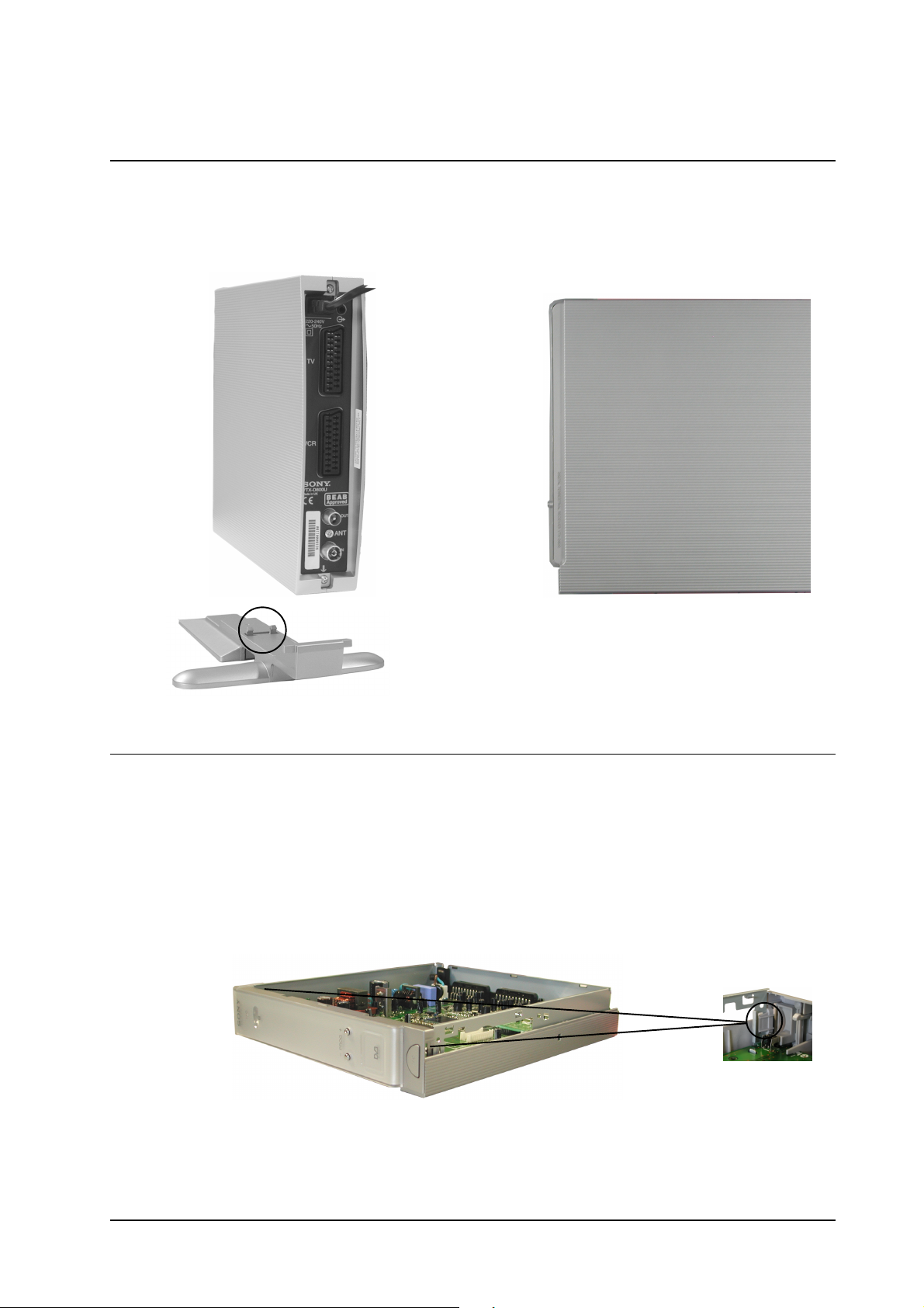
1.1 Cover Removal
Remove the foot by releasing the clips circled and easing the foot carefully away from the unit. Remove the 2
screws located at the rear of the unit (shown arrowed). Lift the front of the cover slightly and slide towards the rear
of the unit until it is clear. Reassembly is the reversal of removal.
==>
Lift cover
gently at this
point.
==>
==>
1.2 Front Panel Removal
Remove the cover as indicated above. Carefully unhook the front panel locating clips from the chassis, pull the
front panel gently forward and lift clear.
Service Manual
Clip located
on both sides
of Front panel
- 4 -

[ 1.3 ] B Board Removal
Remove the cover and front panel as indicated in [1-1] and [1-2]. Disconnect CN600 power cord and remove from
unit. Remove the 1 Philips screw from the rear panel. Remove the 3 Philips screws from the circuit booard. The B
board can then be lifted clear of the chassis.
Screw
CN600
==>
==>
==>
Screws
==>
Screw
[ 1.4 ] Chassis Removal
To remove, lift the front of the chassis slightly to clear the stops and slide forward out of the bottom cover.
Stops
Service Manual
- 5 -
2 Service Mode [TT mode]
There are 2 possible mechanisms for starting TT mode on Sony cook STB’s…
2.1 Special key sequence
The following key sequence entered via the standard remote commander for a particular STB can enable TT
mode. This sequence must be entered…
(1) In full, with no deviation from the sequence from first to last.
(2) With the STB in Standby mode at the start of the sequence.
=>
Should the STB be in active standby at any time (i.e. during software upgrade) it shall not be possible to enter
TT mode.
=>
2.2 Special remote commander data code
It is considered that the sequence described in section 2.1 above is too complex for automated machinery to
enter reliably without the possibility to confuse the state of the STB, therefore in order to aid manufacture the
SIRCS standard defines that in each remote control category the data code ‘1111111’ (0x7f) shall be reserved
and can be used to enter test mode.
For Cook STB products this SIRCS code shall enter TT mode and is valid in the following conditions…
(1) If the unit is in standby. At which point the STB will come out of standby
(2) When the unit is not is standby and there is no menu displayed
(3) When the unit is not tuning (automatically or manual)
(4) Then the unit is not displaying interactive services
The category code is different between each equipment type (DTT, etc) and the correct category code
must be received according to the equipment type.
The test code shall not be made available on any consumer remote commander equipment.
2.3 Exiting TT mode
Sequence number Key
1 DIGIT 1
2 DIGIT 9
3 LEFT CURSOR
4 BLUE
=>
TT mode can be exited using one of the following mechanisms…
(1) Removing the power to the STB
(2) Placing the STB into Standby mode
(3) Entering the command ‘0’
After TT mode is exited any changes to the state of the box will still be effective. It is better to force a box
reset post-TT mode.
Service Manual
- 6 -
4
3 Entering the TT command number
The TT number is entered using the standard digit keys using the category defined for the STB type. Category
codes for equipment types other than this STB’s type must be rejected.
Depending on the type of equipment the number of digits available for commands will vary. Leading zero can
be omitted. If the full compliment of digits is not entered a 3 second time -out period will be required to elapse
before the command is activated. Automated entry mechanisms such as those used during manufacturing
should enter the full compliment of digits in order to avoid the STB and controller getting out of sync.
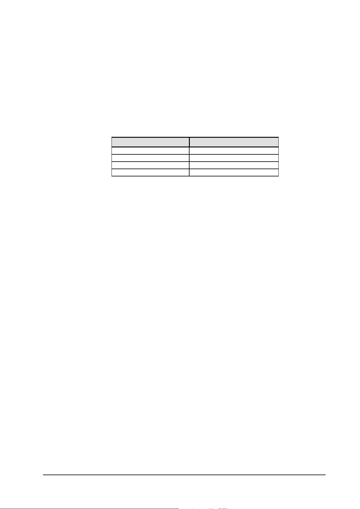
The following are defined digit lengths for current planned models…
Model Number of digits
VTX-D800U 3
VTX-D800E 3
VTX-D800N 3
3.1 Cancelling a command entry
Entering a ‘0’ digit after any other digit entry (thus making the command a multiple of 10) will immediately
reset the display and perform no action.
3.2 Example
VTX-D800U requires 3 digits. Therefore the following sequences would be valid to issue a test command…
Sequence Result
0 ⇒ 1 ⇒ 4
1 ⇒ 4 ⇒ Timeout after 3 seconds
1 ⇒ 0
0 ⇒ Timeout after 3 seconds
0 ⇒ 0 ⇒ 0
Executes command 14
Executes command 14
Does not execute any command (cancels input)
Cancels TT mode
Cancels TT mode
Service Manual
- 7 -
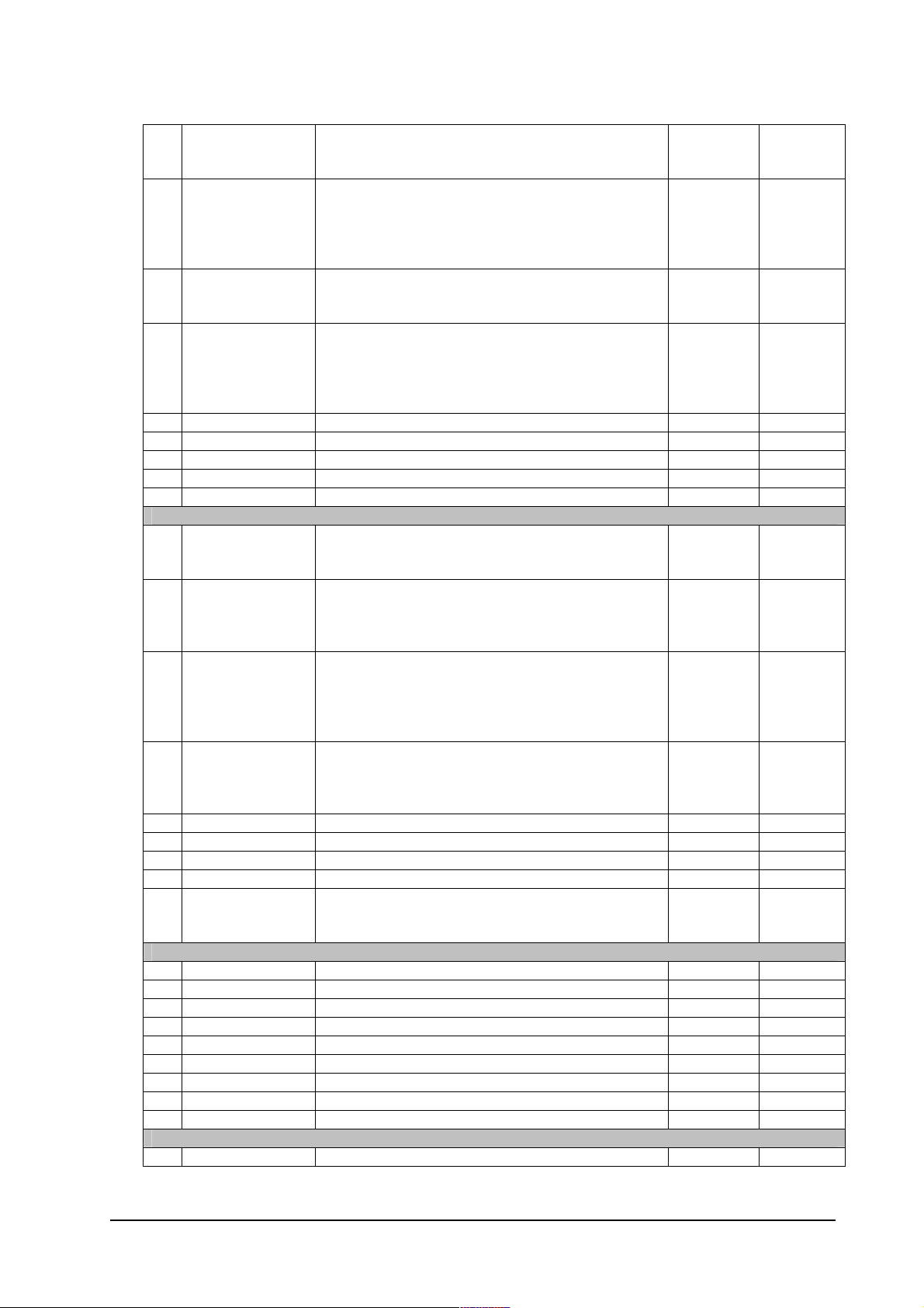
4 List of TT commands
Depending on the STB model the number of digits which are capable of being entered will vary, therefore any
leading zero have been omitted from the TT number defined in the list. Entries should be made according to
the description in section 3.
All commands ending in zero (ie. 0, 10, 20, 30, 40) etc reset the display, cancelling partially entered
commands.
All settings, except those marked “Permanent”, are reset after a power cycle.
TT Name Description Permanent Supported
0 Revert to normal Stops TT mode and returns the STB to normal active
mode.
It does not necessarily revert to the mode of
operation prior to TT mode being entered.
1 STB reset Force the box to reset
This resets the state of the box to just powered on.
STB will power on in standby mode.
2
3
4
5
6 Factory reset &
reboot
7 Factory reset Reset all settings to defaults (shipping) Yes
8 Shipping default
& reboot
9 Shipping default Set the box to shipping condition
SCART/AV
11 Colour bar ON Enable colour bar output on TV & VCR SCART
12 Colour bar OFF Disable colour bar output on TV & VCR SCARTS
13 Smart link test Sends a sequence of commands to the AV link bus.
14 Scart control off Sets pin 8 on all SCART sockets to 0V No
15 Scart control 16:9 Sets pin 8 on all SCART sockets to 16:9 level No
16 Scart control 4:3 Sets pin 8 on all SCART sockets to 4:3 level No
17
18
19
21
22
23
24
25
26
27
28
29
Common interface
Reset all settings to defaults (shipping)
Reboot
Set the box to shipping condition
Tune database is cleared
Reboot - Start-up menu will be activated
Tune database is cleared
When colour bar is enabled the OSD cannot be seen.
Appendix A shows the sequence sent.
Yes
Yes
Yes
No
Service Manual
- 8 -
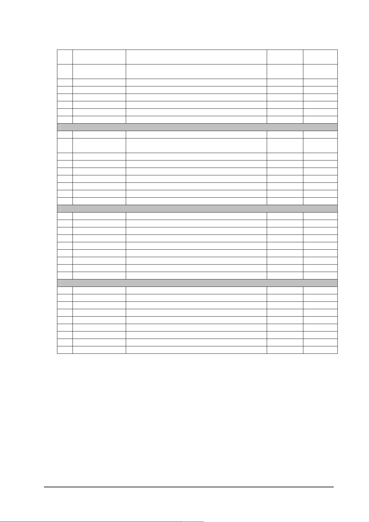
31 Slot 0 bypass Transport stream is set to bypass slot 0.
This command is effective only when there is no CAM
inserted into slot 0.
32 Slot 0 pass thru Transport stream is set to pass out/in slot 0.
This command is effective only when there is no DVB
compliant CAM inserted into slot 0.
If there is no output/input device then the demux will
not receive a valid transport stream.
33 Slot 1 bypass Transport stream is set to bypass slot 1.
This command is effective only when there is no CAM
inserted into slot 1.
34 Slot 1 pass thru Transport stream is set to pass out/in slot 1.
This command is effective only when there is no DVB
compliant CAM inserted into slot 1.
If there is no output/input device then the demux will
not receive a valid transport stream.
35
36
37
38
39
Software upgrade
41 Upgrade Serial Forces a software upgrade from the serial port
STB will reset after loading & TT mode will be
cancelled
Yes
42 Upgrade Ethernet Forces a software upgrade from the Ethernet port (if
available)
STB will reset after loading & TT mode will be
cancelled
Yes No
43 Upgrade off-air Forces a software upgrade from the current service
A change of service, satellite, etc will be done as
required.
STB will reset after loading & TT mode will be
cancelled
Yes
44 Upgrade Memory
stick
Forces a software upgrade from the Memory stick (if
available)
STB will reset after loading & TT mode will be
cancelled
Yes
45
46
47
48
49 Allow downgrade On next SW update, update the software even if the
version is older than, or the same as, the current
version
Yes
Screen control
51
52
53
54
55
56
57
58
59
I/O
61 LED OFF Sets all LED’s Off
Service Manual
- 9 -
62 LED ON 1 Sets all LED’s as Colour 1 (Red)
If bicolour LED and Colour 2 ON, it will be Orange
63 LED ON 2 Sets all LED’s as Colour 2 (Green)
If bicolour LED and Colour 1 ON, it will be Orange
64
65
66
67
68
69
Tuner
71 Show tuner status Shows the tuner status display on the OSD
72 Clear tune info Erase the tune database
Sets all channels to an un-tuned state
Yes
73
74
75
76
77
78
79
81
82
83
84
85
86
87
88
89
91
92
93
94
95
96
97
98
99
Service Manual
- 10 -
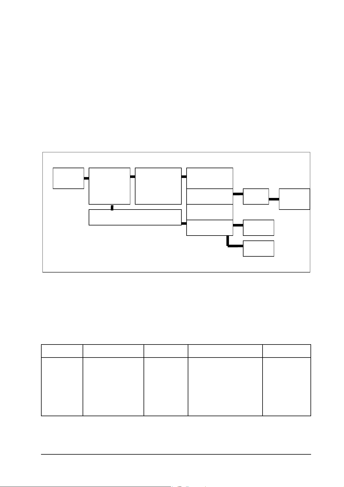
5.0: Power supply
A
The power supply in an integrated part of the Main PWB, and contains the following functional blocks: -
The main components are:-
1. Mains Plug, Lead and input filter
2. Primary and PWM Controller
3. Transformer and outputs
4. Feedback Circuit
5. Post Regulation Circuits.
Input
Filter
Primary &
Transformer
32.5V Output
Controller
+5V
udio
Feedback Circuit
21V Output
5V Output
3.3V Output
+12V
2V5
1V5
The output of this power supply can be measured at the following positions on the PWB, and should be within the
tolerances for each of the supply rails (marked on the PWB):-
Label / Rail JL Position Vnom Vmin Vmax
33v J1 33 30 35
12v G3 12 11.4 12.6
5v J2 5 4.75 5.25
3v3 J3 3.3 3.14 3.46
2v5 F4 2.5 2.3 2.7
1v5 D3 1.5 1.43 1.57
Service Manual
- 11 -

5.1: Power Supply Detailed Description
The most common failures will be fixed by replacing the following components.
PRIMARY BLAST KIT:- F600, D600, D602 D601, IC600, PH600, IC602, D604.
The components detailed below have the following functions:
Fuse, F600. T1.25A 250V
Always replace the fuse, with the same type and ratings as the one removed.
The fuse will fail if the following occurs:
1. A Primary component fails
2. The input circuit was over stressed
3. or both.
When the fuse fails check the following components: VDR600, C600, L602, D600, D602 D601, IC600.
If all the components look and measure OK, then replace the fuse and apply power, most probable cause is that the
VDR clamped a mains surge and caused the fuse to fail.
If any of the components have failed, then replace as necessary.
VDR600, 620V Metal Oxide Varistor
If this component has failed then the unit has seen a massive mains voltage surge, probably from Lightening or
similar phenomenon. Replace the following components:-
F600
VDR600
C600
L602
If the primary circuit has been damaged in any other way, replace the components as necessary.
If the unit is exposed to a massive mains surge then the feedback components may have been damaged. Also
Check PH600, IC602, D604.
D600 Bridge Rectifier
It is common for bridge rectifier to fail under repetitive mains surge conditions. Check the value of the TH601, if
it is lower than 10 Ohms replace it. TH601 is there to protect the bridge rectifier.
Before you apply power after changing D600 check the other primary parts, if D600 failed F600 should be open
and often the primary blast kit will need to be changed.
IC600 Primary Controller
This IC houses the primary MOSFET and the PWM controller. Check the DRAIN SOURCE characteristic to see if
it’s failed. Often when IC600 fails there are signs of damage to the package. In most cases this will fail short. In
some rare cases the part will fail open. If IC600 fails the primary blast kit needs to be replaced.
D601 Flyback Diode
This diode catches the transformers flyback voltage, and pushes the energy into the snubber circuit. This circuit
will often fail as a result of IC600 failing.
If damaged primary replace the blast kit.
Service Manual
- 12 -
 Loading...