

Sony VPL-X1000E, VPL-X1000M Operating Instruction
VPL-X1000U/X1000E/X1000M
3-865-632-12 (1)
LCD Data Projector
Operating Instructions
Mode d’emploi
Manual de instrucciones
EN
F
ES
VPL-X1000U
VPL-X1000E
VPL-X1000M
1998 by Sony Corporation
English
WARNING
To prevent fire or shock hazard, do not
expose the unit to rain or moisture.
To avoid electrical shock, do not open the
cabinet. Refer servicing to qualified
personnel only.
This symbol is intended to alert the
user to the presence of uninsulated
“dangerous voltage” within the
product’s enclosure that may be of
sufficient magnitude to constitute a risk
of electric shock to persons.
This symbol is intended to alert the
user to the presence of important
operating and maintenance (servicing)
instructions in the literature
accompanying the appliance.
For the customers of VPL-X1000E/X1000M
LASER RADIATION
DO NOT STARE INTO BEAM
CLASS 2 LASER PRODUCT
RAYONNEMENT LASER
NE PAS REGARDER DANS LE FAISCEAU
APPAREIL A LASER DE CLASSE 2
LASER–STRAHLING
NIGHT IN DEN STRAHL BLICKEN
LASER KLASSE 2
MAX OUTPUT:1mW
WAVE LENGTH:645nm
This label is located on the
rear of the Remote
Commander.
This label is located on the
side of the Remote
Commander.
For the customers of VPL-X1000U
CAUTION
LASER RADIATION
DO NOT STARE INTO BEAM
WAVE LENGTH:645nm
MAX OUTPUT:1mW
CLASS II LASER PRODUCT
COMPLIES WITH DHHS 21 CFR
SUBCHAPTER J
SONY CORPORATION
6-7-35 KITASHINAGAWA
SHINAGAWA-KU,TOKYO,JAPAN
A
MANUFACTURED;
AVOID EXPOSURE
RADIATION IS EMITTED
FROM THIS APERTURE.
-
LASER
This label is located on the
rear of the Remote
Commander.
This label is located on the
rear of the Remote
Commander.
For the customers in the USA
This equipment has been tested and found to comply with
the limits for a Class A digital device, pursuant to Part 15 of
the FCC Rules. These limits are designed to provide
reasonable protection against harmful interference when the
equipment is operated in a commercial environment. This
equipment generates, uses, and can radiate radio frequency
energy and, if not installed and used in accordance with the
instruction manual, may cause harmful interference to radio
communications. Operation of this equipment in a residential
area is likely to cause harmful interference in which case the
user will be required to correct the interference at his own
expense.
You are cautioned that any changes or modifications not
expressly approved in this manual could void your authority
to operate this equipment.
Laser light shines out of this window.
Caution
use of controls or adjustments or performance of procedures
other than those specified herein may result in hazardous
radiation exposure.
Notes
• Do not aim the laser at people or not look into the laser
transmitter.
• When the Remote Commander causes mulfunction, consult
with qualified Sony personnel. We change the Remote
Commander as new one according to the guarantee.
2 (EN)
For the customers in Canada
This Class A digital apparatus complies with Canadian ICES-
003.
For the customers in the United Kingdom
WARNING
THIS APPARATUS MUST BE EARTHED
IMPORTANT
The wires in this mains lead are coloured in accordance with
the following code:
Green-and-Yellow: Earth
Blue: Neutral
Brown: Live
As the colours of the wires in the mains lead of this apparatus
may not correspond with the coloured markings identifying the
terminals in your plug proceed as follows:
The wire which is coloured green-and-yellow must be
connected to the terminal in the plug which is marked by the
letter E or by the safety earth symbol Y or coloured green or
green-and-yellow.
The wire which is coloured blue must be connected to the
terminal which is marked with the letter N or coloured black.
The wire which is coloured brown must be connected to the
terminal which is marked with the letter L or coloured red.
Voor de klanten in Nederland
Bij dit product zijn batterijen geleverd. Wanneer
deze leeg zijn, moet u ze niet weggooien maar
inleveren als KCA.
The socket-outlet should be installed near the equipment
and be easily accessible.
3 (EN)

4 (EN)
Table of Contents
Overview
Setting up and projecting
Precautions ................................................................6 (EN)
Features...................................................................... 8 (EN)
Location and Function of Controls .......................... 9 (EN)
Front .......................................................................... 9 (EN)
Rear ......................................................................... 13 (EN)
Remote Commander ............................................... 15 (EN)
Installing the Projector............................................ 17 (EN)
Connecting ............................................................... 18 (EN)
Connecting with a Computer .................................. 18 (EN)
Connecting with a VCR, 15k RGB/Component
Equipment .......................................................... 20 (EN)
Using the RGB IN/OUT connector on INPUT B as a
monitor output connector ................................... 21 (EN)
Projecting .................................................................22 (EN)
EN
English
Adjustments and settings using the menu
Using the MENU....................................................... 25 (EN)
The PICTURE CTRL Menu ......................................26 (EN)
The INPUT SETTING Menu ..................................... 28 (EN)
The SET SETTING Menu ......................................... 31 (EN)
Installation
Installation Examples .............................................. 33 (EN)
Floor Installation ..................................................... 33 (EN)
Ceiling Installation .................................................. 34 (EN)
Unsuitable Installation ............................................ 35 (EN)
Notes on Installation ............................................... 36 (EN)
Maintenance
Maintenance ............................................................. 37 (EN)
Note on the Time to Replace the Lamp .................. 37 (EN)
Cleaning the Air Filter ............................................ 37 (EN)
Troubleshooting ...................................................... 38 (EN)
Other
Specifications .......................................................... 40 (EN)
Index ......................................................................... 46 (EN)
5 (EN)

Precautions
On safety
• Check that the operating voltage of your unit is identical with the voltage
of your local power supply. If voltage adaptation is required, consult with
qualified Sony personnel.
• Should any liquid or solid object fall into the cabinet, unplug the unit and
have it checked by qualified personnel before operating it further.
• Unplug the unit from the wall outlet if it is not to be used for several
days.
• To disconnect the cord, pull it out by the plug. Never pull the cord itself.
• The wall outlet should be near the unit and easily accessible.
• The unit is not disconnected from the AC power source (mains) as long
as it is connected to the wall outlet, even if the unit itself has been turned
off.
• Do not look into the lens while the lamp is on.
• Do not aim the laser at people or not look into the laser transmitter.
• Do not place your hand or objects near the ventilation holes — the air
coming out is hot.
• When the projector is mounted on the ceiling, the Sony PSS-600
Projector Suspension Support must be used for installation.
• Be careful not to catch your fingers by the adjusters when you lift up the
projector. Do not push hard on the top of the projector with the adjusters
out.
On illumination
• To obtain the best picture, the front of the screen should not be exposed
to direct lighting or sunlight.
• Ceiling-mounted spot lighting is recommended. Use a cover over
fluorescent lamps to avoid lowering the contrast ratio.
• Cover any windows that face the screen with opaque draperies.
• It is desirable to install the projector in a room where floor and walls are
not of light-reflecting material. If the floor and walls are of reflecting
material, it is recommended that the carpet and wall paper be changed to
a dark color.
On preventing internal heat build-up
After you turn off the power with the I /
or on the control panel, do not disconnect the unit from the wall outlet
while the cooling fan is still running.
Caution
The projector is equipped with ventilation holes (intake) at the bottom and
ventilation holes (exhaust) on the front. Do not block or place anything
near these holes, or internal heat build-up may occur, causing picture
degradation or damage to the projector.
u
key on the Remote Commander
6 (EN)

On cleaning
On repacking
Overview
• To keep the cabinet looking new, periodically clean it with a soft cloth.
Stubborn stains may be removed with a cloth lightly dampened with a
mild detergent solution. Never use strong solvents, such as thinner,
benzene, or abrasive cleansers, since these will damage the cabinet.
• Avoid touching the lens. To remove dust on the lens, use a soft dry cloth.
Do not use a damp cloth, detergent solution, or thinner.
• Clean the filter at regular intervals.
• Save the original shipping carton and packing material; they will come in
handy if you ever have to ship your unit. For maximum protection,
repack your unit as it was originally packed at the factory.
7 (EN)

Features
High brightness, high picture quality
• High brightness
The LCD panel with aspherical microlens and the 120 W UHP lamp
allow high brightness (light output 1100 ANSI lumen) and excellent
uniformity on the picture.
• High resolution
By adopting three 1.3-inch, about 790,000-pixel XGA panels, this
projector offers resolution of 1024 × 768 dots for RGB input and 750
horizontal TV lines for video input.
Simple setup
• Sony original APA (Auto Pixel Alignment) function
You can get the clearest picture automatically by simply pressing the
APA key when the signal is input from a computer.
• Simple setup with external equipment
This projector has 38 kinds of preset data for input signals. You can get a
suitable picture by connecting an equipment with supplied cable and
pressing the APA key.
Easy presentation
Accepts various input signals
• Remote Commander with mouse control and laser pointer functions
You can operate a computer with the Remote Commander since the unit
has a build-in mouse receiver. For your presentation, you can use the
laser pointer built in the Remote Commander as well.
• High portability
This projector has been downsized to 5.9 kg (13 lb) of mass and 12 cm (4
3
/4 inches) of height. In addition, the carrying handle and the front cover
that holds the Remote Commander make it all the more convenient to
carry.
• Scan converter loaded
This projector has a build-in scan converter which converts the input
signal within 1024 × 768 dots.
• Compatible input signals
This projector accepts video signals of the composite, S video, and
1)
component as well as the 15 k RGB, VGA
, SVGA1) XGA1), and
SXGA1) signals, which all can be displayed.
• Compatible with five color systems
2)
NTSC, PAL, SECAM, NTSC 4.43
, or PAL-M color system can be
selected automatically or manually.
Note on the VPL-X1000E model
The optional IFB-X600E Interface Board is required for video composite
input.
..........................................................................................................................................................................................................
1) VGA, SVGA, XGA, and SXGA are registered trademarks of the International Business Machines Corporation,
8 (EN)
U.S.A.
2) NTSC4.43 is the color system used when playing back a video recorded on NTSC on a NTSC4.43 system VCR.
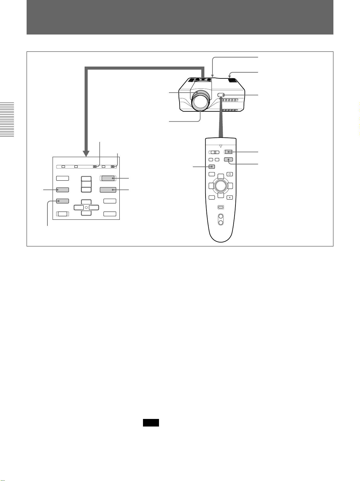
Location and Function of Controls
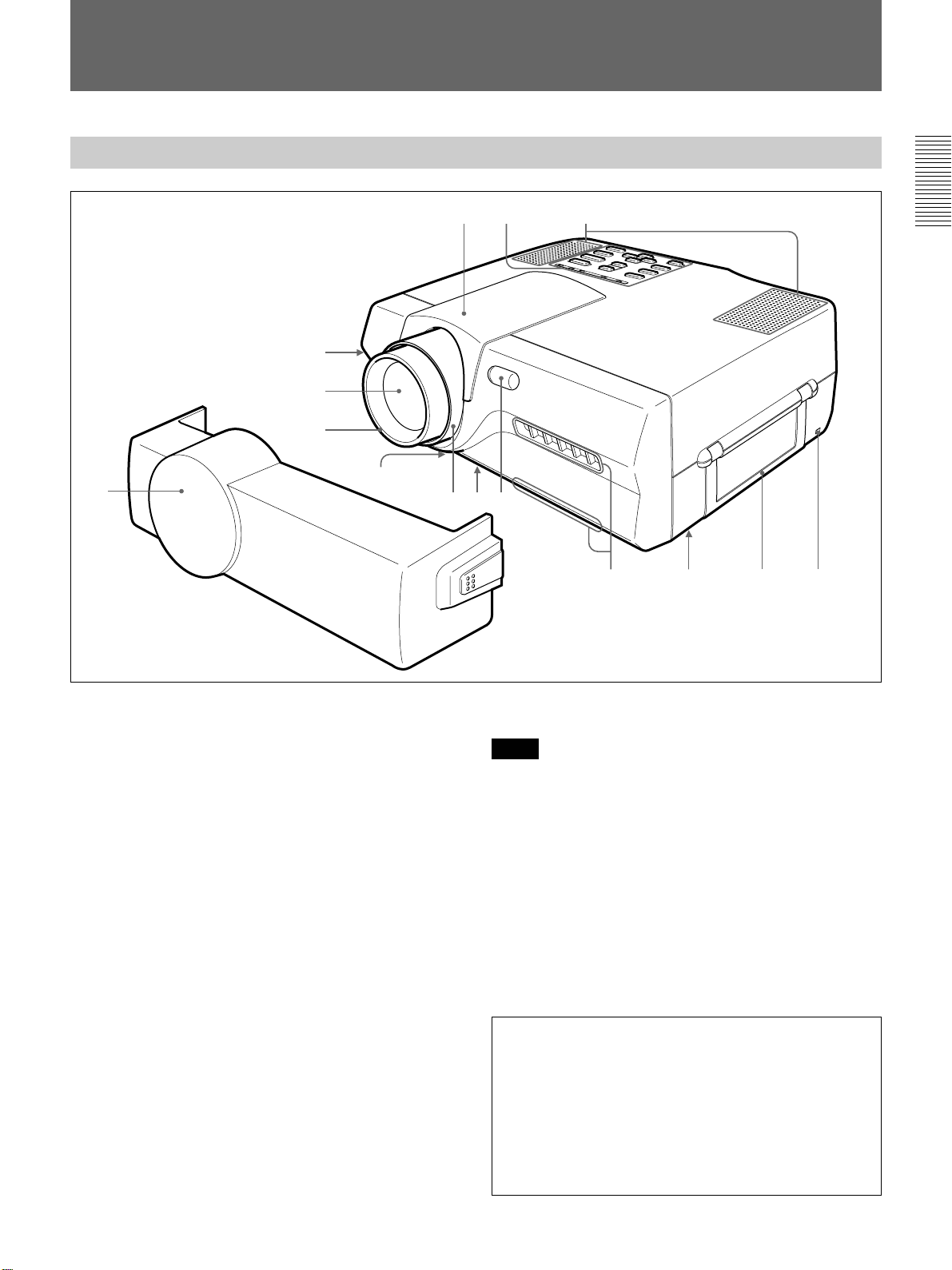
Front
!£!¢!∞
2
3
4
5
1
6
87
1 Front cover
Installs the Remote Commander in the back of the
front cover.
2 Front adjuster button
3 Lens
Remove the front cover and the lens cap before
projection.
4 Focus ring
Adjusts the picture focus.
5 Ventilation holes (bottom / intake)
6 Zoom ring
Adjusts the size of the picture.
7 Front adjuster
Used to keep the projector level if it is installed on an
uneven surface.
For details on how to use the adjusters, see “How to use the
adjusters” on page 11 (EN).
8 Front remote control detector
09
9 Ventilation holes (exhaust)
Notes
• Do not place anything near the ventilation holes as it
may cause internal heat build-up.
• Do not place your hand or objects near the ventilation
holes — the air coming out is hot.
!º Lamp cover (bottom)
!¡ Carrying handle
Used for carrying the projector.
!™ Security lock
Connects to an optional security cable (Kensington’s).
The security lock corresponds to Kensington’s
MicroSaver Security System.
If you have any comment, contact
Kensington
2853 Campus Drive, San Mates, CA 94403
U.S.A.
Tel: 800-535-4242: extension 3348
Home page address: http://www.kensington.com/
!¡ !™
9 (EN)
Location and Function of Controls
!£ Speakers
!¢ Control panel
For details, see “Control panel” on page 11 (EN).
!∞ Lens hood
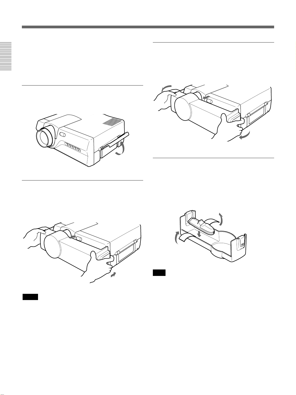
How to use the carrying handle
Pull up the handle from the projector for carrying.
How to attach the front cover
Attach the front cover on the front cabinet by
stretching out both right and left sides on the front
cover.
How to remove the front cover
Remove the front cover from the front cabinet by
stretching out both right and left sides on the front
cover.
How to install the Remote Commander in
the front cover
Install the Remote Commander in the back of the front
cover and fix it with the velcro tapes. When housing
the Remote Commander, make sure that the infrared
transmitter faces outside and rear faces upwards.
Notes
• Do not plug or turn on the projector when the front
cover is attached.
• Do not hold the front cover when you carry the
projector.
10 (EN)
Note
Set the COMMAND ON/OFF switch on the Remote
Commander to OFF before installing the Remote
Commander.
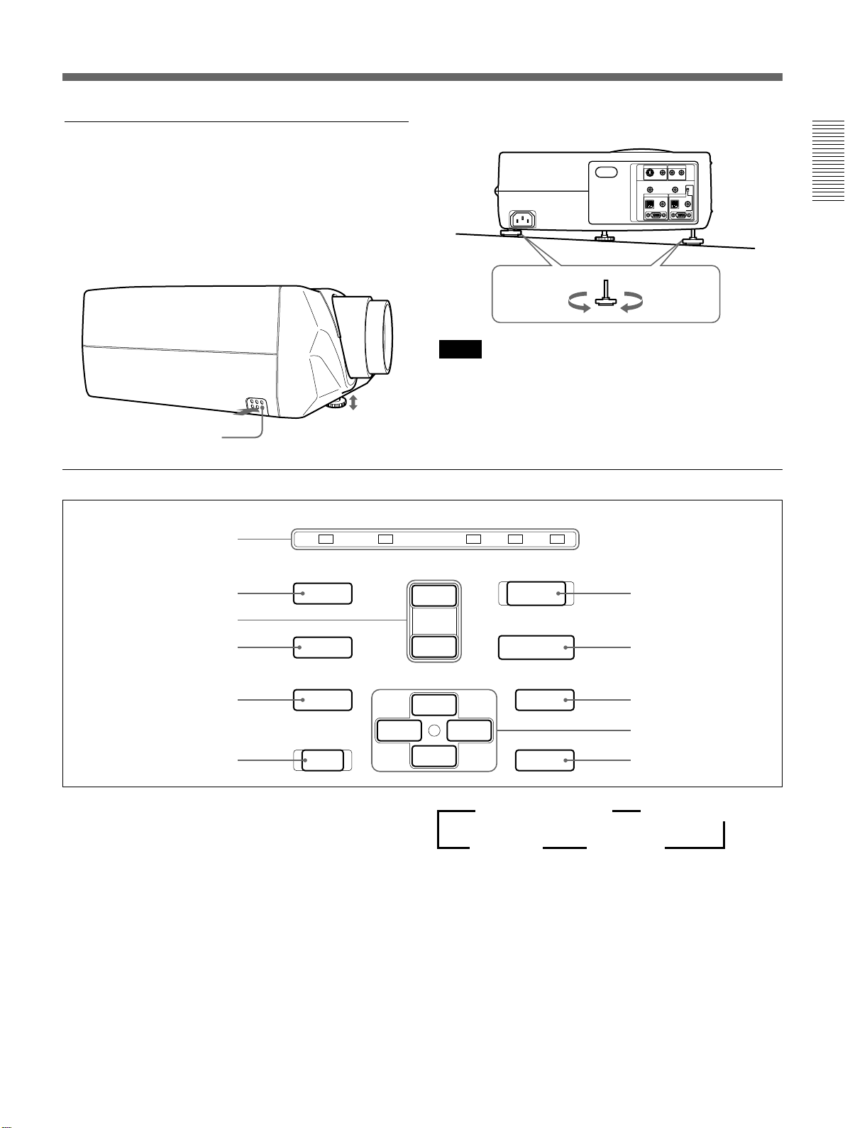
How to use the adjusters
While lifting the projector, adjust the height so that the
projector becomes level.
There are one adjuster at the front and two at the rear
of the projector.
As for the front adjuster, press the front adjuster
button while lifting the projector to adjust the height.
Turn the front adjuster for fine adjustment.
As for the rear adjusters, turn them for adjustment.
Front adjuster button
Control panel
To lower
the projector
Notes
•
Be careful not to let the projector down on your fingers.
To raise
the projector
• Do not push hard on the top of the projector with the
adjusters out.
• Do not force the rear adjusters when you turn them.
Using too much force may result in damage.
POWER
SAVINGSTANDBYTEMP/FANLAMP/COVER
ON
!¡
01
9
8
7
LIGHT
PATTERN
APA
+
VOLUME
–
V
I / u
INPUT
MENU
2
3
B
6
1
I / u (
on / standby) key
Turns on and off the projector when the projector is in
the standby mode. The ON indicator lights in green
when the power is turned on.
When turning off the power, press the
twice following the message on the screen, or press
and hold the key for about one second.
For details on steps for turning off the power, see “To turn off
the power” on page 24 (EN).
2 INPUT key
Selects the input signal. Each time you press the key,
the input signal switches as follows (When the RGB
IN/OUT select switch is set to OUT, you cannot select
INPUT B.):
RESET
I / u
key
4
5
v
b
ENTER
n VIDEO/AUDIO IN n S VIDEO/AUDIO IN
INPUT B N INPUT A N
Note on the VPL-X1000E model
The optional IFB-X600E Interface Board is required
for VIDEO IN and AUDIO IN jacks.
3 MENU key
Displays the on-screen menu. Press again to clear the
menu.
4 Arrow keys (V/v/B/b)
Used to select the menu or to make various
adjustments.
(Continued)
11 (EN)

Location and Function of Controls
5 ENTER key
Enters the settings of items in the menu system.
6 RESET key
Resets the value of an item back to its factory preset
value. This key functions when the menu or a setting
item is displayed on the screen.
(
7 APA
Adjusts a picture to be projected clearest automatically
while a signal from the computer is input.
8 PATTERN key
Displays an H pattern on the screen for focus, zoom
adjustments. Press again to clear the pattern.
9 VOLUME +/– keys
Adjust the volume of the built-in speakers and output
level of the AUDIO OUT jacks.
+ : Increases the volume.
– : Decreases the volume.
!º LIGHT key
Lights the back lighting (orange) for the keys on the
control panel when the power is turned on. Press again
to turn off the back lighting.
Auto Pixel Alignment) key
!¡ Indicators
ON: Lights in green when the power is turned on.
Flashes in green while the cooling fan runs after
turning off the power with the
runs for about 90 seconds after turning off the
power.
The ON indicator flashes quickly for the first 30
seconds.
During this time, you cannot turn the power back
I / u
on with the
POWER SAVING: Lights up when the projector is
in the power saving mode. When POWER
SAVING in the SET SETTING menu is set to
ON, the projector goes into the power saving
mode if no signal is input for 10 minutes.
Although the lamp goes out, the cooling fan keeps
running. In the power saving mode, any key does
not function for the first 30 seconds. The power
saving mode is canceled when a signal is input or
any key is pressed.
STANDBY: Lights in red when the AC power cord
is plugged into the wall outlet.
Once in the standby mode, you can turn on the
projector with the
Commander or on the control panel.
key.
I / u
key on the Remote
I / u
key. The fan
TEMP (Temperature)/FAN: Lights up or flashes
under the following conditions:
• Lights up when temperature inside the projector
becomes unusually high.
• Flashes when the fan is broken.
LAMP/COVER: Lights up or flashes under the
following conditions:
• Lights up when the lamp has reached the end of
its life.
• Flashes when the lamp cover or air filter cover is
not secured firmly.
For details on the LAMP/COVER and the TEMP/FAN
indicators, see page 39 (EN).
12 (EN)
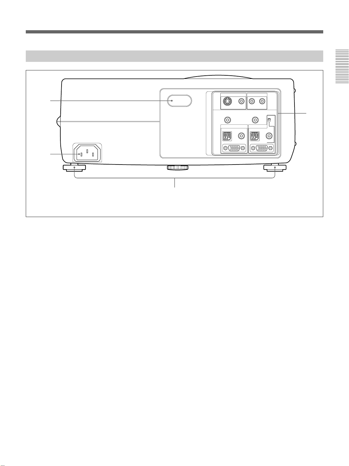
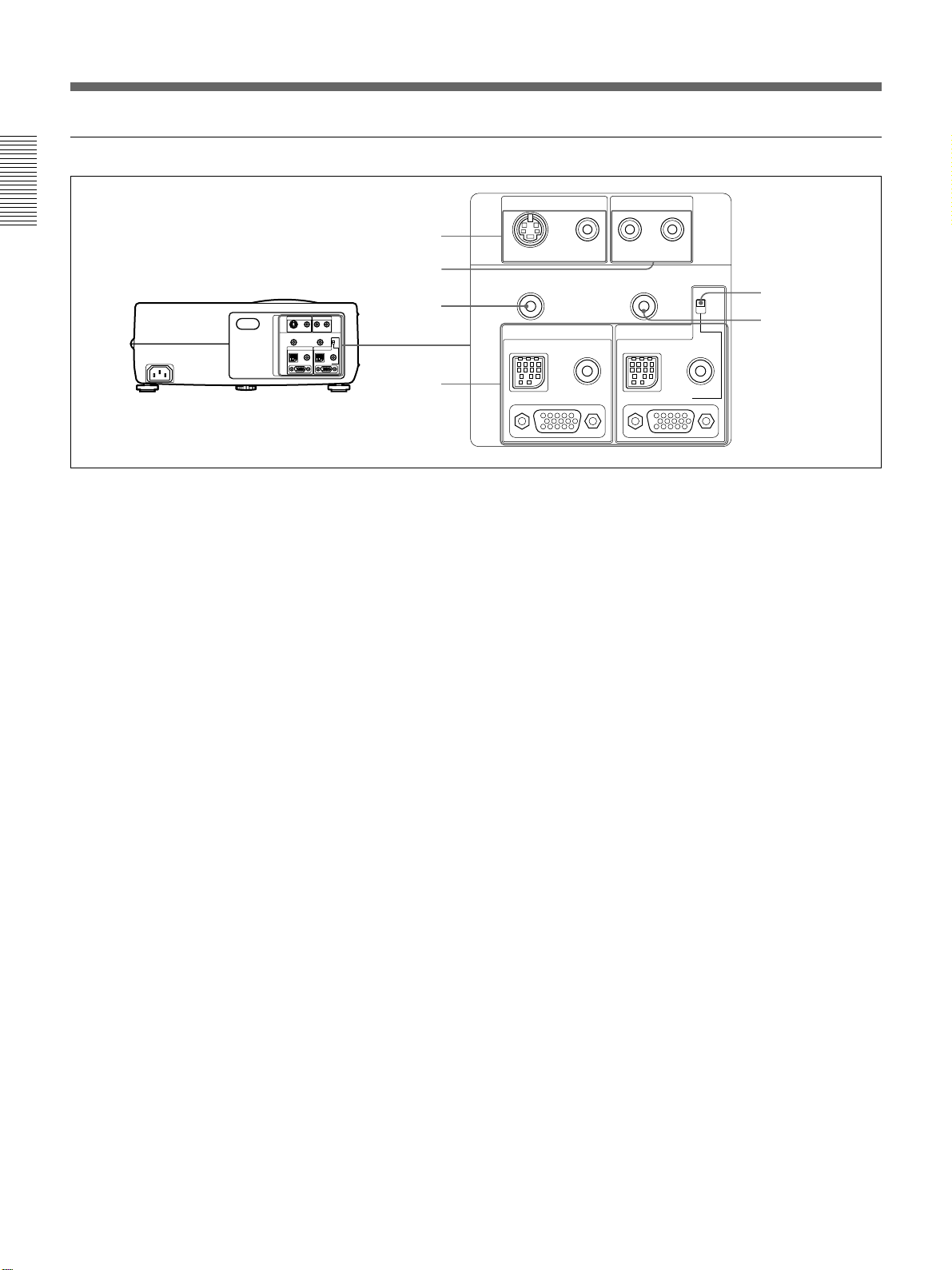
Rear
1
2
The illustration above is the VPL-X1000U/M model.
1 Rear remote control detector
2 AC IN socket
Connects the supplied AC power cord.
3
VIDEO IN
S VIDEO
AUDIO OUT
INPUT A
MOUSE AUDIO
(MONO)
VIDEO L
CONTROL S IN
AUDIO IN
R
PLUG IN POWER
INPUT B
MOUSE AUDIO
IN/OUT
IN
OUT
4
3 Rear adjusters
Used to keep the projector level if it is installed on an
uneven surface.
For details on using the adjusters, see “How to use the
adjusters” on page 11 (EN) .
4 Connector panel
For details, see page 14 (EN).
13 (EN)
Location and Function of Controls
Connector panel
1
2
Rear
3
4
The illustration above is the VPL-X1000U/M model.
1 VIDEO IN jacks
Connect to external video equipment such as a VCR.
S VIDEO (mini DIN 4-pin): Connects to the S video
output (Y/C video output) of a video equipment.
VIDEO (phono type): Connects to the composite
video output of video equipment.
2 AUDIO IN L (MONO)/R jacks (phono type)
Connect to the audio output of equipment. For stereo
equipment, use both the L and R jacks; for monaural
equipment, use the L (MONO) jack only.
VIDEO IN
S VIDEO
AUDIO OUT
MOUSE AUDIO
VIDEO L
INPUT A
AUDIO IN
(MONO)
CONTROL S IN
PLUG IN POWER
R
INPUT B
MOUSE AUDIO
IN/OUT
IN
OUT
5
6
RGB input (INPUT A) / RGB IN/OUT (INPUT B)
(HD D-sub 15-pin, female): Connects to the
monitor output on a computer using the supplied
cable. When inputting a component, or 15k RGB
signal, use the optional cable.
As for the RGB IN/OUT connector on INPUT B,
you can use it as an output connecor with the RGB
IN/OUT select switch. This connector outputs the
signal which input through the RGB input
connector on INPUT A.
3 AUDIO OUT jack (stereo minijack)
Connects to external active speakers.
The volume of the speakers can be controled by the
VOLUME keys on the Remote Commander or the
control panel.
4 INPUT A/INPUT B connectors
Connect to external equipment such as a computer.
You can control the mouse signal with the Remote
Commander.
MOUSE (13-pin): Connects to the mouse port on a
computer to control the mouse function using the
supplied mouse cable.
AUDIO (stereo minijack): Connects to the audio
output on a computer to input the audio signal.
5 RGB IN/OUT select switch
Switches the input/output of the RGB IN/OUT
connector on INPUT B.
IN: Functions as an input connector.
OUT: Functions as an output connector. The RGB
IN/OUT connector outputs the signal which input
through the RGB input connector on INPUT A.
The MOUSE connector and AUDIO jack on
INPUT B do not function at this time.
6 CONTROL S IN/PLUG IN POWER jack
(DC 5 V output, stereo minijack)
Connects to the CONTROL S OUT jack on the
supplied Remote Commander with the stereo
connecting cable (not supplied) when using it as a
wired Remote Commander. You do not need to install
the batteries since the power is supplied via this jack.
Batteries are required when you use the laser pointer
function.
Note on the VPL-X1000E model
The optional IFB-X600E Interface Board is required
for the VIDEO IN 1 and AUDIO IN 2 jacks.
14 (EN)
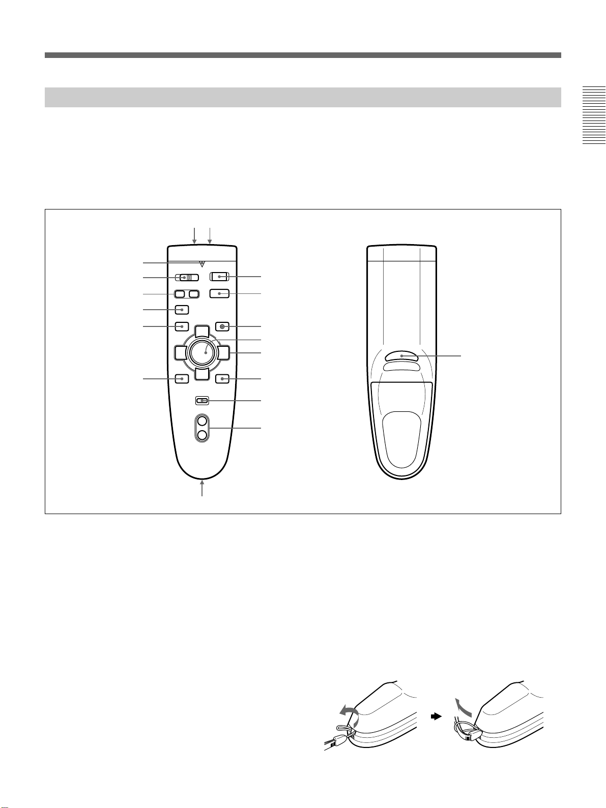
Remote Commander
The Remote Commander can be used as a wireless or
wired Remote Commander.
The keys which have the same names as on the control
panel function identically.
You can control a connected computer using the
Remote Commander.
Front Rear
!§
!∞
!¢
!£
!™
!¶ !•
COMMAND
MUTING
PICTUREAUDIO
APA
MENU
I / u
ONOFF
INPUT
1
2
LASER
V
3
4
!¡
ENTER
v
RESET
bB
R CLICK
5
6
7
VOLUME
+
–
8
For details, see “Connecting with a Computer” on page
18 (EN).
Notes on laser beam
• Do not look into the laser transmitter.
• Do not aim the laser at people.
!ª
9, 0
1
I / u
key
6 R CLICK key
Functions as a right button on a mouse. When
2 INPUT key
connected to a Macintosh
1)
computer, the R CLICK
key functions as a mouse button.
3 LASER key
Emits laser beam from the laser transmitter when you
7 RESET key
press this key.
8 VOLUME +/– keys
4 Joy stick
Functions as a mouse of a computer connected to the
unit.
9 Strap holder
Attaches the supplied strap.
5 Arrow keys (V/v/B/b)
(Continued)
..........................................................................................................................................................................................................
1) Macintosh is a registered trademark of Apple Computer, Inc.
15 (EN)
Location and Function of Controls
!º CONTROL S OUT jack (stereo minijack)
Connects to the CONTROL S IN jack on the projector
with the connecting cable (not supplied) when using
the Remote Commander as a wired one. In this case,
you do not need to install the batteries since the power
is supplied via the CONTROL S IN jack on the
projector.
!¡ ENTER key
!™ MENU key
!£ APA (Auto Pixel Alignment) key
!¢ MUTING keys
Cut off the picture and sound.
PICTURE: Cuts off the picture. Press again to
restore the picture.
AUDIO: Cuts off the sound from speakers and
AUDIO OUT jack. Press again or press the
VOLUME + key to restore the sound.
!∞ COMMAND ON/OFF switch
When this switch is set to OFF, no key on the Remote
Commander function. This saves the battery power.
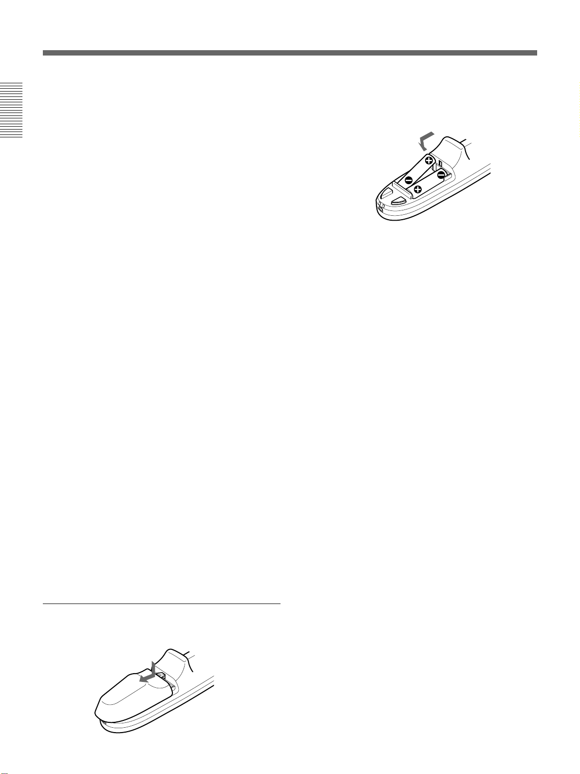
2 Install the two size AA (R6) batteries (supplied)
with the correct polarity.
Be sure to install
the battery from
the ’ side.
3 Replace the lid.
Notes on batteries
• Make sure that the battery orientation is correct when
inserting batteries.
• Do not mix an old battery with a new one, or
different types of batteries.
• If you will not use the Remote Commander for a long
time, remove the batteries to avoid damage from
battery leakage. If batteries have leaked, remove
them, wipe the battery compartment dry and replace
the batteries with new ones.
!§ Transmission indicator
Lights up when you press a key on the Remote
Commander.
This indicator does not light up when you use the laser
pointer.
!¶ Infrared transmitter
!• Laser transmitter
!ª L CLICK key
Functions as a left button on a mouse. When connected
to a Macintosh computer, the L CLICK key functions
as a mouse button.
Battery installation
1 Push and slide to open the lid.
Notes on wireless Remote Commander
operation
• Make sure that there is nothing to obstruct the
infrared beam between the Remote Commander and
the remote control detector on the projector.
• The operation range is limited. The shorter the
distance between the Remote Commander and the
projector is, the wider the angle within which the
commander can control the projector.
• The remote control detectors on the projector do not
function when the connecting cable (not supplied) is
connected to the projector. When using the Remote
Commander as a wireless Remote Commander,
remove the connecting cable from both the Remote
Commander and the projector.
Note on wired Remote Commander operation
The laser pointer function does not work when you use
the Remote Commander as a wired one without
batteries.
16 (EN)
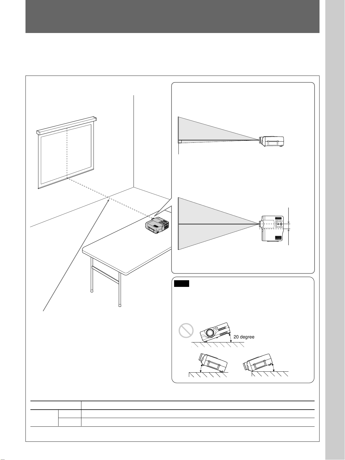
Installing the Projector
This section describes the installation arrangements for installing the
projector on a table. For ceiling installation, consult with qualified Sony
personnel (see page 34 (EN)).
Horizontal center
of the screen
Setting up and projecting
Adjust the vertical and horizontal positioning of the projector.
Vertical positioning (side view)
Screen
Adjust the height of the projector so that the center of
the lens is just above the bottom edge of the screen.
Horizontal positioning (top view)
Screen
The distance between the lens and the screen varies
depending on the size of the screen. Use the following table
as a guide.
Center of
the lens
57.5 mm
(2 3/8
inches)
Center of
the unit
Adjust the horizontal positioning of the projector so that the lens
is aligned with the horizontal center of the screen.
Note
Install the projector to be level.
Avoid followings which may cause malfunction.
• The projector topples over on its side.
• The projector titles more than 20 degrees.
20 degrees
20 degrees
20 degrees
Unit: m (feet)
Screen size (inches) 40 60 80 100 120 150 180 200 250 300
Distance
Minimum 1.6 (5.1) 2.4 (7.8) 3.2 (10.5) 4.0 (13.3) 4.9 (15.9) 6.1 (20.0) 7.3 (24.1) 8.2 (26.8) 10.2 (33.6) 11.2 (40.4)
Maximum 2.0 (6.5) 3.0 (9.9) 4.1 (13.3) 5.1 (16.7) 6.1 (20.1) 7.7 (25.2) 9.2 (30.3) 10.3 (33.7) 12.9 (42.2) 15.5 (50.7)
For detailed information on installation measurements, see page 33 (EN).
17 (EN)
Connecting
Note on the VPL-X1000E model
The optional IFB-X600E Interface Board is required for the VIDEO IN
and AUDIO IN jacks.
Connecting with a Computer
This section describes how to connect the projector with a computer.
For details on how to connect VCR or other equipment, see page 20 (EN).
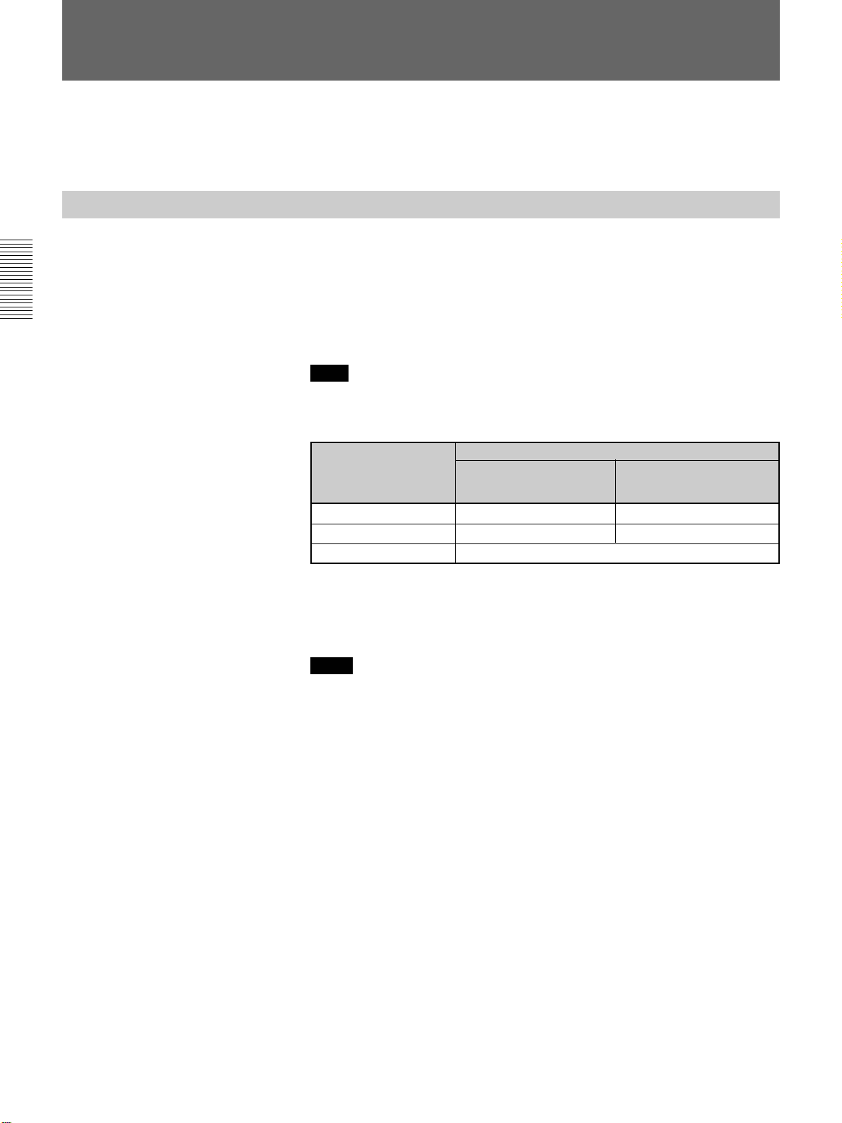
When the projector is connected to a computer, you can control the mouse
of a computer by the Remote Commander.
The R/L CLICK keys and joy stick function as follows.
Note
Make sure that there is nothing to obstruct the infrared beam between the
Remote Commander and the remoter control detector on the projector.
Key and joy stick
IBM PC/AT
compatible, Serial
R CLICK (front) Right button Mouse button
L CLICK (rear) Left button Mouse button
Joy stick Corresponds with the movements of the mouse
a) IBM PC/AT is a registered trademark of International Business Machines
Corporation, U.S.A.
a)
Function
Macintosh
Also refer to the instruction manual of equipment to be connected.
Notes
• This unit accepts the VGA, SVGA, XGA, and SXGA signals. However,
we recommend you to set the output mode of your computer to the XGA
mode for the external monitor. (For Macintosh computer, set the output
mode to 19-inch mode.)
• If you set your computer, such as a notebook type IBM PC/AT
compatible, to output the signal to both the display of your computer and
the external monitor, the picture of the external monitor may not appear
properly. In such cases, set the output mode of your computer to output
the signal to only the external monitor.
For details, refer to the operating instructions supplied with your computer.
18 (EN)
When making connections, be sure to:
• turn off all equipment before making any connections.
• use the proper cables for each connection.
• insert the plugs of the cables properly; plugs that are not fully inserted
often generate noise. When pulling out a cable, be sure to pull it out from
the plug, not the cable itself.
Notes
• Connect all the connecting cables to the INPUT A connector when you
input a signal from the INPUT A connector.
Connect all the cables to the INPUT B connector when you input a signal
from the INPUT B connector as well.
• When connecting to INPUT B, make sure that the RGB IN/OUT select
switch is set to IN.
• Supplied mouse cable may not work properly according to your
computer.
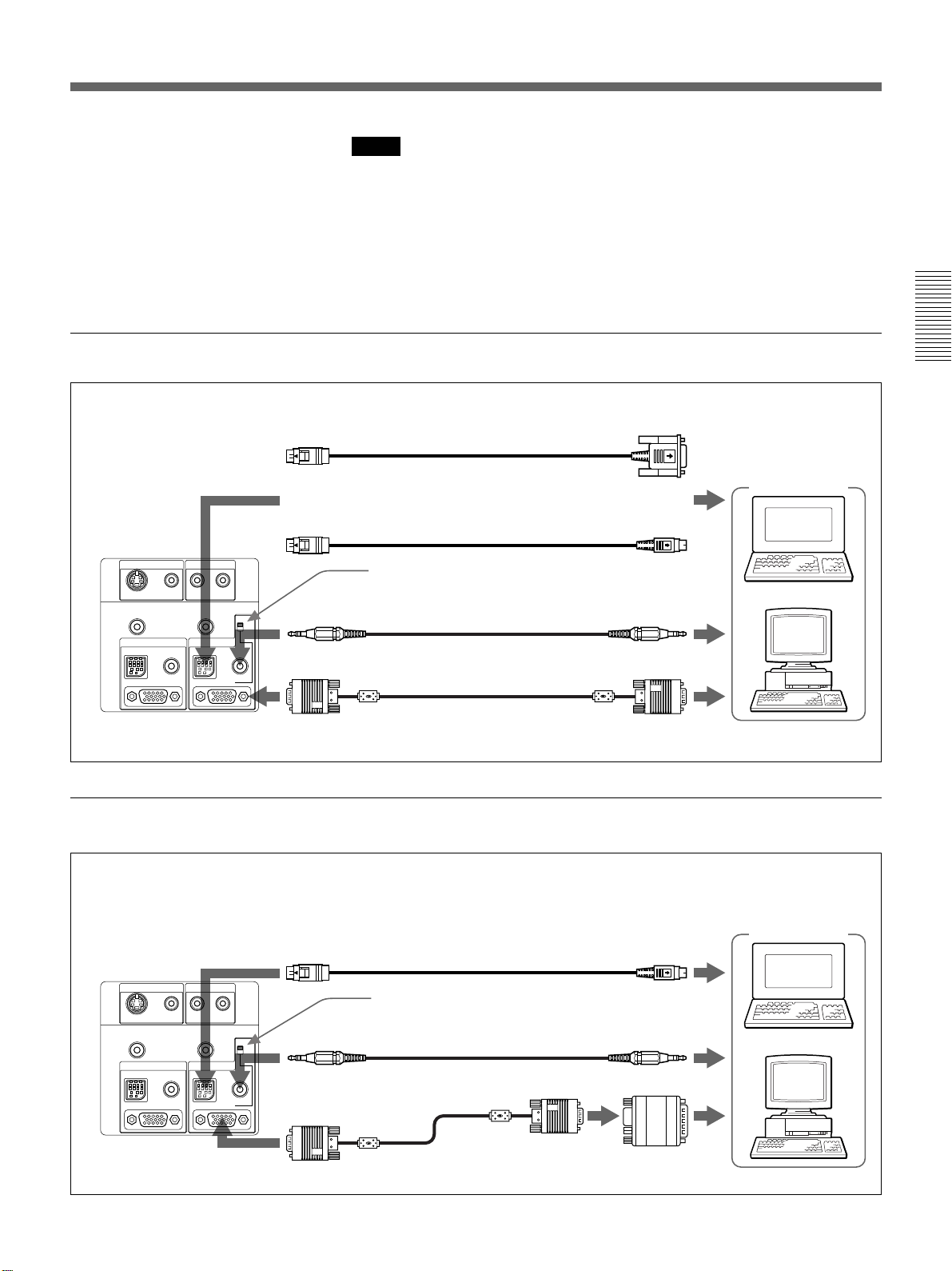
When connecting with an IBM PC/AT compatible computer
SIC-S21 Mouse cable for serial port (supplied)
to serial port
to INPUT A or
INPUT B
or
SIC-S22 Mouse cable for PS/2 port (supplied)
Rear
VIDEO L
CONTROL S IN
AUDIO IN
(MONO)
R
PLUG IN POWER
INPUT B
MOUSE AUDIO
IN/OUT
Set this switch to IN.
IN
OUT
Stereo audio connecting
cable (not supplied)
SMF-401 HD D-sub 15-pin
cable (supplied)
VIDEO IN
S VIDEO
AUDIO OUT
INPUT A
MOUSE AUDIO
When connecting with a Macintosh computer
For details on the DIP switch setting of the adapter, see page 43 (EN).
to INPUT A or
Rear
S VIDEO
AUDIO OUT
MOUSE AUDIO
VIDEO IN
INPUT A
VIDEO L
CONTROL S IN
INPUT B
AUDIO IN
(MONO)
R
PLUG IN POWER
INPUT B
MOUSE AUDIO
IN/OUT
IN
OUT
SIC-S20 Mouse cable (supplied)
Set this switch to IN.
Stereo audio connecting
cable (not supplied)
SMF-401 HD D-sub 15pin cable (supplied)
Computer
to mouse port
to audio out
to monitor out
Computer
to mouse port
to audio out
to monitor out
Signal adapter
(supplied)
19 (EN)
Connecting
VIDEO IN
INPUT A
MOUSE AUDIO
S VIDEO
AUDIO OUT
INPUT B
MOUSE AUDIO
IN/OUT
CONTROL S IN
PLUG IN POWER
VIDEO L
(MONO)
R
AUDIO IN
IN
OUT
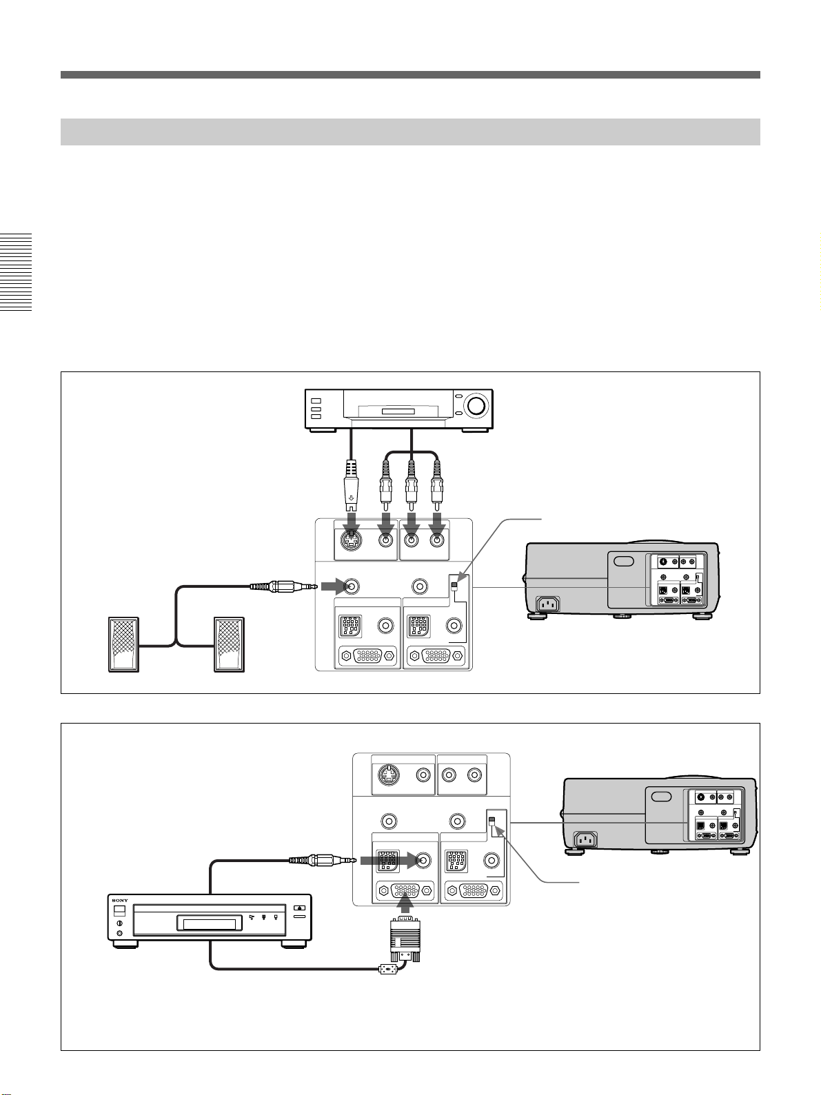
Connecting with a VCR, 15k RGB/Component Equipment
This section describes how to connect the projector with a VCR, external
active speakers and 15k RGB/component equipment.
For details on how to connect a computer, see page 18 (EN).
Also refer to the instruction manuals of equipment to be connected.
When making connections, be sure to:
• turn off all equipment before making any connections.
• use the proper cables for each connection.
• insert the plugs of the cables properly; plugs that are not fully inserted
often generate noise. When pulling out a cable, be sure to pull it out from
the plug, not the cable itself.
VCR
to S video
output
S-Video cable
(not supplied)
VIDEO IN
S VIDEO
AUDIO OUT
INPUT A
MOUSE AUDIO
(MONO)
VIDEO L
CONTROL S IN
AUDIO IN
PLUG IN POWER
MOUSE AUDIO
INPUT B
IN/OUT
to audio/video
outputs
Audio/video cable
(VPL-X1000U/M: supplied
VPL-X1000E: supplied with the IFB-X600E Interface Board)
Set this switch to IN.
Rear
R
IN
OUT
Note on the VPL-X1000E model
The optional IFB-X600E Interface Board is required for
the VIDEO IN and AUDIO IN jacks.
Active speakers
Rear
Stereo audio
connecting cable
(not supplied)
15k RGB/component
equipment
to RGB/component output
Notes
Set this switch to IN.
SMF-402 Signal Cable (not supplied)
3X phono jack ˜ HD D-sub 15-pin (male)
or
SMF-400 Video Signal Cable (not supplied)
5X BNC ˜ HD D-sub 15-pin (male)
• Select the RGB or component signal with INPUT-A or INPUT-B in the SET SETTING menu.
• Use the composite sync signal when you input the external sync signal from 15k RGB/component equipment.
• When connecting to INPUT B, make sure that the RGB IN/OUT select switch is set to IN.
20 (EN)
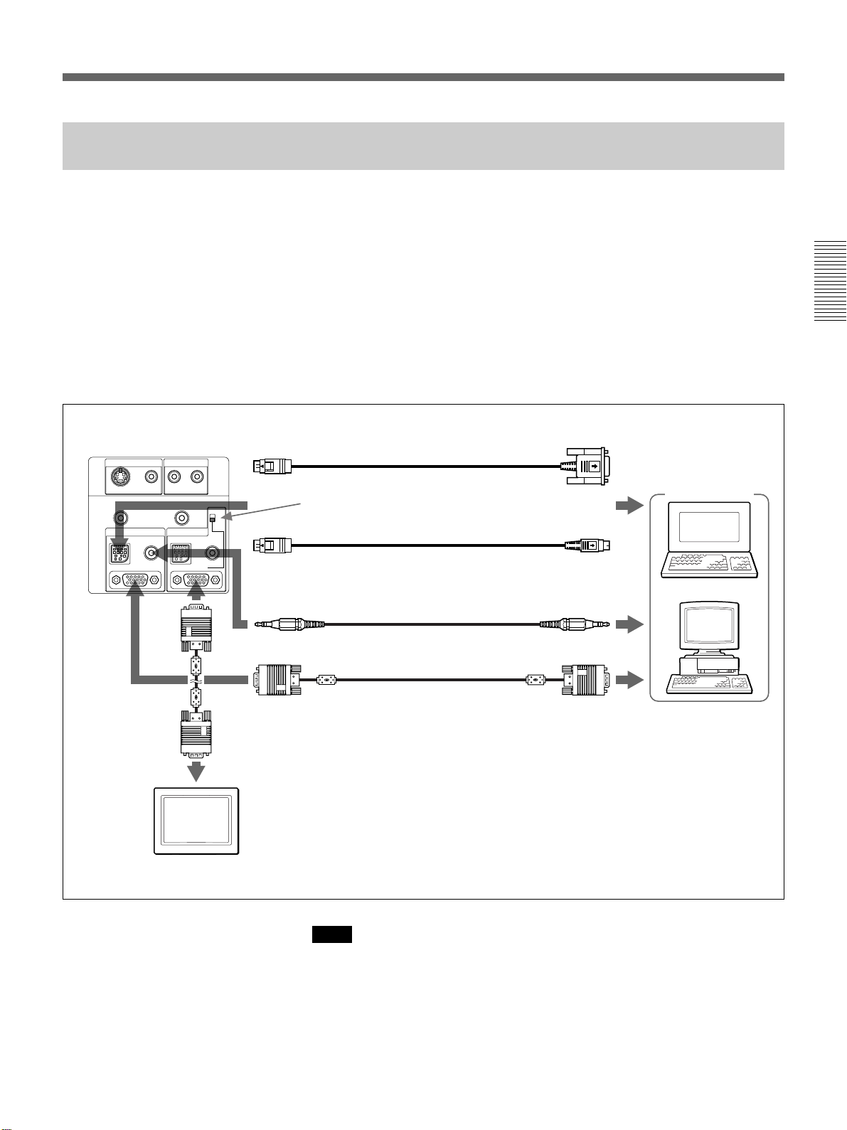
Using the RGB IN/OUT connector on INPUT B as a monitor output
connector
This section describes connections when using the RGB IN/OUT
connector on INPUT B as a monitor output connector.
When making connections, be sure to:
• turn off all equipment before making any connections.
• use the proper cables for each connection.
• insert the plugs of the cables properly; plugs that are not fully inserted
often generate noise. When pulling out a cable, be sure to pull it out from
the plug, not the cable itself.
• Make sure that the RGB IN/OUT select switch is set to OUT.
Rear
S VIDEO
AUDIO OUT
VIDEO IN
VIDEO L
INPUT A
MOUSE AUDIO
to monitor
input
AUDIO IN
(MONO)
CONTROL S IN
PLUG IN POWER
INPUT B
MOUSE AUDIO
IN/OUT
to INPUT A
R
IN
OUT
SMF-401 HD D-sub 15-pin
cable (not supplied)
SIC-S21 Mouse cable for serial port (supplied)
Set this switch to OUT.
SIC-S22 Mouse cable for PS/2 port (supplied)
Stereo audio connecting cable (not supplied)
SMF-401 HD D-sub 15-pin cable (supplied)
to serial port
Computer
to mouse port
to audio out
to monitor out
Monitor
Note
When the RGB IN/OUT select switch is set to OUT, the MOUSE
connector and AUDIO jack on INPUT B do not function.
21 (EN)
Projecting
Rear remote control detector
1
APA key
LIGHT
PATTERN
APA
RESET
STANDBY indicator
+
VOLUME
–
V
b
B
v
POWER
SAVINGSTANDBYTEMP/FANLAMP/COVER
I / u
INPUT
MENU
ENTER
ON indicator
ON
2
34
5
Front remote control detector
4, 6
COMMAND
I / u
APA key
MUTING
APA
MENU
ENTER
PICTUREAUDIO
ONOFF
V
v
RESET
VOLUME
+
–
INPUT
LASER
bB
R CLICK
2
3
1 After all equipment is connected completely, plug the AC power cord
into the wall outlet.
The STANDBY indicator lights in red and the projector goes into the
standby mode.
u
2 Press the I /
key on the Remote Commander or on the control panel.
The ON indicator lights in green.
3 Turn on equipment connected to the projector. Press the INPUT key on
the Remote Commander or on the control panel to select the input
source.
INPUT A: Selects audio and video signals input from the INPUT A
connector.
INPUT B: Selects audio and video signals input from the INPUT B
connector.
VIDEO: Selects audio and video signals input from the AUDIO IN/
VIDEO (VIDEO IN) jacks.
S VIDEO: Selects audio and video signals input from the AUDIO IN/
S VIDEO (VIDEO IN) jacks.
Note
The AUDIO IN jacks are used as audio outputs of both VIDEO and S
VIDEO.
22 (EN)
Note on the VPL-X1000E model
The optional IFB-X600E Interface Board is required for selecting
VIDEO.
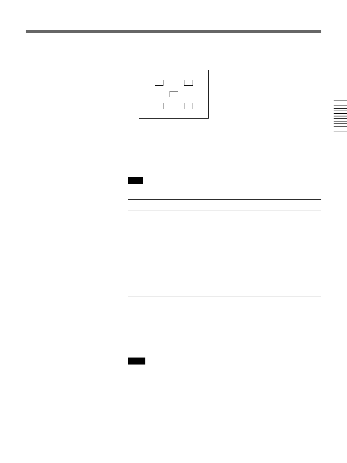
4 Press the PATTERN key on the control panel to display the H pattern,
and turn the focus ring to adjust the focus.
HHHH HHHH
HHHH HHHH
HHHH
HHHH
HHHH HHHH
HHHH HHHH
Press the PATTERN key again to clear the pattern.
5 Turn the zoom ring to adjust the size of the picture.
6 Turn the focus ring again to adjust the focus.
Note
Do not look into the lens when the projector lamp is on.
To Press
Adjust the volume the VOLUME +/– keys on the control
panel or on the Remoter Commander.
To get the clearest picture
Cut off the sound the AUDIO MUTING key on the
Remote Commander. To restore the
sound, press the AUDIO MUTING key
again or press the VOLUME + key.
Cut off the picture the PICTURE MUTING key on the
Remote Commander. To restore the
picture, press the PICTURE MUTING
key again.
You can get the suitable picture when a signal from the computer is input.
Press the APA key on the Remote Commander or on the control panel.
The picture is automatically adjusted to be projected clearest.
Notes
• Adjust the signal when the still picture is displayed on the screen.
• If you switch the input signal or re-connect a computer, press the APA
key again to get the suitable picture.
• “ADJUSTING” appears on the screen. Press the APA key again during
the adjustment to restore the original screen.
• “Complete!” appears on the screen when the picture is adjusted properly.
The picture may not be adjusted properly depending on the kinds of input
signals.
• Adjust DOT PHASE in the INPUT SETTING menu when you adjust the
picture manually.
For details on DOT PHASE, see page 28 (EN).
23 (EN)
Projecting
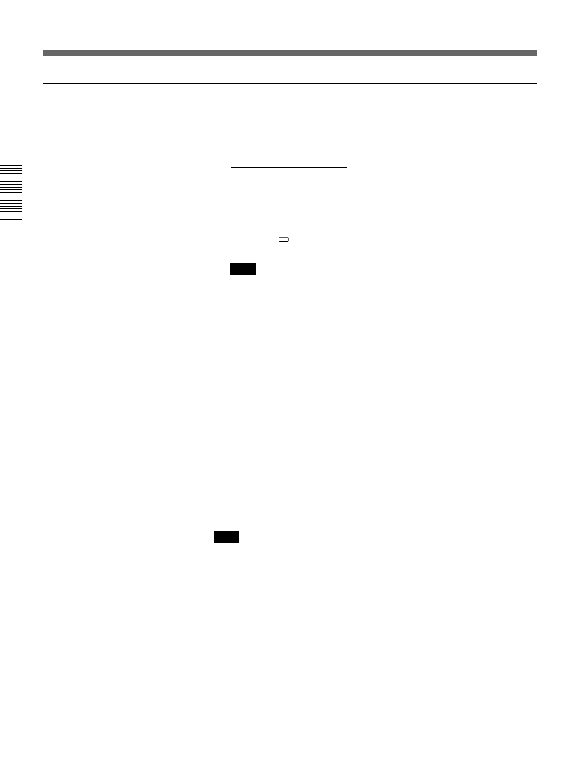
To turn off the power
1 Press the I /
The following message appears to confirm if you want to turn off the
power.
POWE R O FF?
Please press key again.
Note
The message will disappear if you press any key except the I / u key,
or if you do not press any key for five seconds.
2 Press the I /
again.
The ON indicator flashes in green and the fan continues to run for
about 90 seconds to reduce the internal heat. Also, the ON indicator
flashes quickly for the first 30 seconds. During this time, you will not
be able to turn the power back on with the I /
u
key on the Remote Commander or on the control panel.
I / u
u
key on the Remote Commander or on the control panel
u
key.
3 Unplug the AC power cord from the wall outlet after the fan stops
running and the STANDBY indicator lights in red.
When you cannot confirm the on-screen message
When you cannot confirm the on-screen message in a certain condition,
u
you can turn off the power by holding the I /
Commander or on the control panel for about one second.
Note
Do not unplug the AC power cord while the fan is still running;
otherwise, the fan will stop although the internal heat is still
high, leading to breakdown of the projector.
key on the Remote
24 (EN)
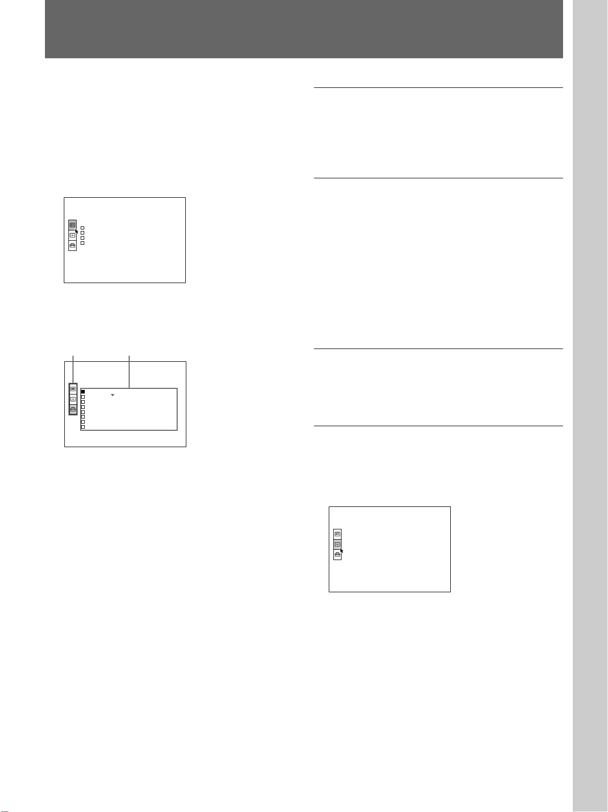
Using the MENU
V I DEO NO I NPUT
INPUT SETTING
NO I N PU T –
Cannot ad j us t t h i s i t em.
Adjustments and settings using the menu
The projector is equipped with an on-screen menu for
making various adjustments and settings.
To select the language used in the menu, see page
32 (EN).
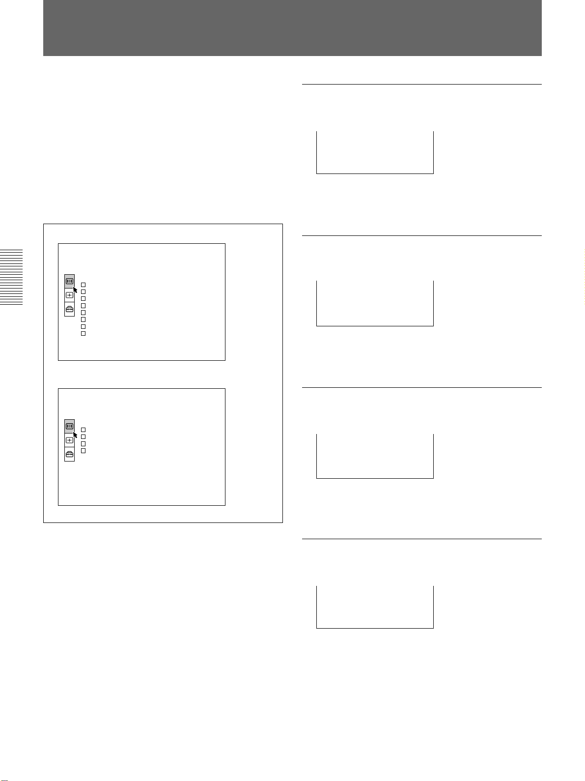
1 Press the MENU key.
The menu display appears.
The menu presently selected is highlighted in blue.
P ICTURE CTRL
CONT RAST : 8 0
BR IGHT : 50
GAMMA MODE :GRAPH I CS
COLOR TEMP: H I GH
I NPUT–A
2 Use the V or v key to select a menu, then press the
b or ENTER key.
The selected menu appears.
Menus Setting items
SET SETT I NG
STATUS: ON
I NPUT –A : RGB
I NPUT –B : RGB
LANGUAGE: ENGLI SH
I N ST A L L A T I ON : F L OOR– FRON T
SPEAKER: ON
POWER SAV I NG: OFF
S I RCS RECE I VER : F RONT&REAR
INPUT–A
To clear the menu display
Press the MENU key.
The menu display disappears automatically if no key is
pressed for one minute.
To reset items that have been adjusted
Press the RESET key.
“Complete!” appears on the screen and the settings
appearing on the screen will be reset to their factory
preset values.
Items which can be reset are:
• “CONTRAST”, “BRIGHT”, “COLOR”, “HUE”, and
“SHARP” in the PICTURE CTRL menu
• “DOT PHASE”, “SIZE”, and “SHIFT” in the INPUT
SETTING menu.
About the memory of the settings
The settings are automatically stored in the projector
memory.
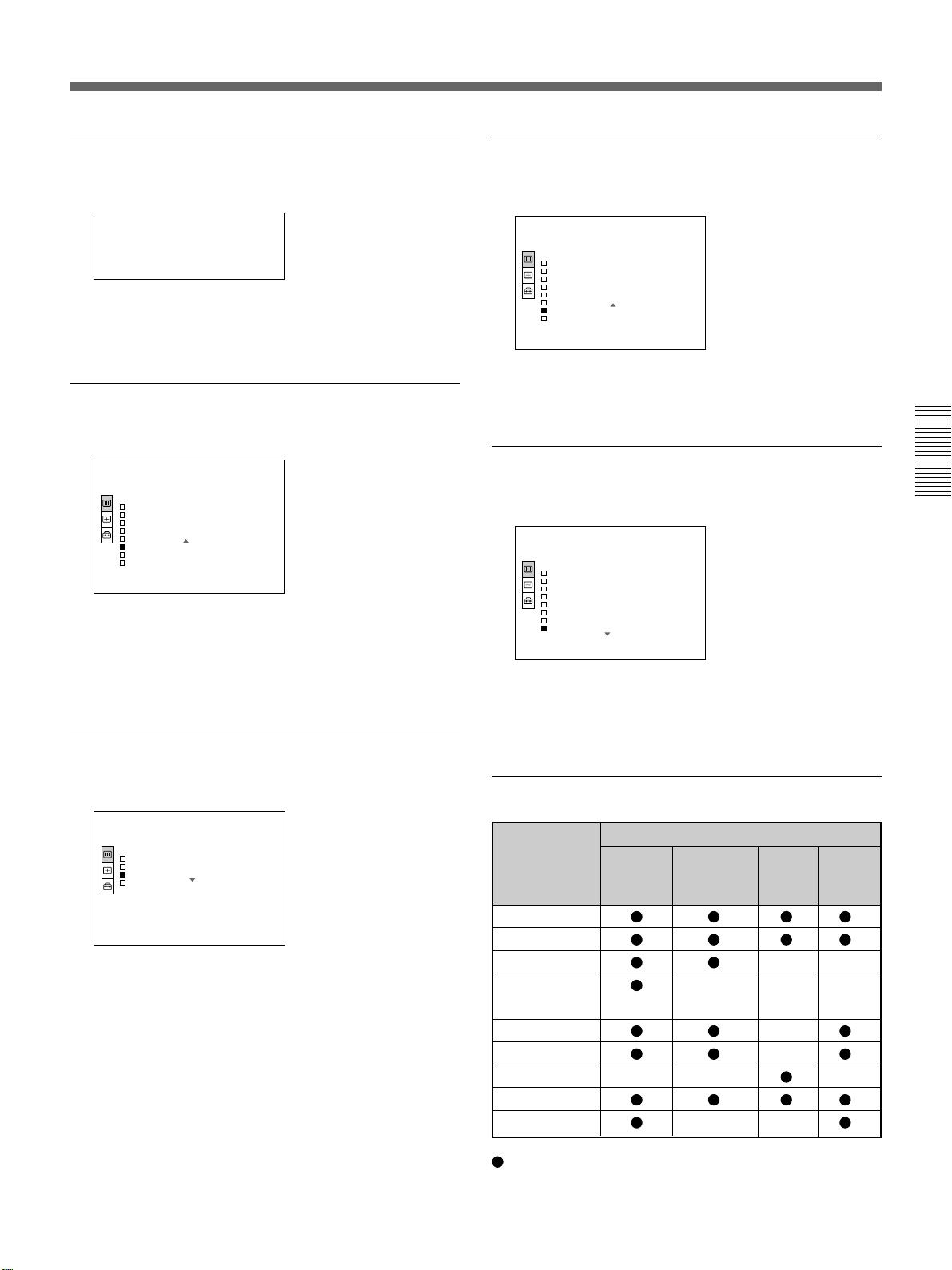
When no signal is input
3 Make setting or adjustment on an item.
For details on setting individual items, see the relevant
menu pages.
When there is no input signal, “NO INPUT-Cannot
adjust this item.” appears on the screen, and each item
cannot be adjusted.
25 (EN)
The PICTURE CTRL Menu
CONT RA ST : 8 0
BR I GHT : 50
COL OR : 5 0
HUE : 50
The PICTURE CTRL (control) menu is used for
adjusting the picture.
Unadjustable items depending on the input signal are
not displayed in the menu.
Note on the VPL-X1000E model
The optional IFB-X600E Interface Board is required
for inputting the video signal. If you do not install the
video board into the unit, the video signal cannot be
selected.
When the video signal is input
P I CTURE CTRL
CONTRAST : 8 0
BR I GHT : 5 0
COL OR : 5 0
HUE : 5 0
SHARP : 5 0
D.PICTURE:OFF
COL OR TEMP : L OW
COLOR SYS: AUTO
VIDEO
CONTRAST
Adjusts the picture contrast.
The higher the setting, the greater the contrast.
The lower the setting, the lower the contrast.
BRIGHT
Adjusts the picture brightness.
The higher the setting, the brighter the picture.
The lower the setting, the darker the picture.
When the RGB signal is input
P I CTURE CTRL
CONTRAST : 8 0
BR I GHT : 5 0
GAMMA MODE : GRAPH I CS
COL OR TEMP : H I GH
I NPUT –A
Operation
1. Select an item
Use the V or v key to select the item, then press the b
or ENTER key.
2. Adjust an item
• When changing the adjustment level:
To increase the number, press the V or b key.
To decrease the number, press the v or B key.
Press the ENTER key to restore the original screen.
• When changing the setting:
Press the V or v key to change the setting.
Press the ENTER or B key to restore the original
screen.
COLOR
Adjusts color intensity.
The higher the setting, the greater the intensity.
The lower the setting, the lower the intensity.
HUE
Adjusts skin tones.
The higher the setting, the picture becomes greenish.
The lower the setting, the picture becomes purplish.
26 (EN)
SHARP
VIDEO
P I CTURE CTRL
CONT RA ST : 8 0
BR I GHT : 5 0
COLOR : 5 0
HUE : 5 0
SHARP : 5 0
D.PICTURE:OFF
COLOR TEMP: LOW
COLOR SYS : AUTO
VIDEO
P I CTURE CTRL
CONT RA ST : 8 0
BR I GHT : 5 0
COLOR : 5 0
HUE : 5 0
SHARP : 5 0
D.PICTURE:OFF
COLOR TEMP: LOW
COLOR SYS : AUTO
COLOR TEMP
Adjusts the picture sharpness.
SHARP : 5 0
The higher the setting, the sharper the picture.
The lower the setting, the softer the picture.
D. (Dynamic) PICTURE
Emphasizes the black color.
P I CTURE CTRL
CONT RA ST : 8 0
BR I GHT : 5 0
COLOR : 5 0
HUE : 5 0
SHARP : 5 0
D.PICTURE:OFF
COLOR TEMP: LOW
COLOR SYS : AUTO
VIDEO
ON: Emphasizes the black color to produce a bolder
“dynamic” picture.
OFF: Reproduces the dark portions of the picture
accurately, in accordance with the source signal.
GAMMA MODE
Adjusts the color temperature.
HIGH: Makes the white color bluish.
LOW: Makes the white color reddish.
COLOR SYS (System)
Selects the color system of the input signal.
Normally, set to AUTO.
If the picture is distorted or colorless, select the color
system according to the input signal.
Selects a gamma correction curve.
GRAPHICS: Improves the reproduction of half
TEXT: Contrasts black and white. Suitable for
P I CTURE CTRL
CONT RA ST : 8 0
BR I GHT : 5 0
GAMMA MODE : GRAPH I CS
COL OR TEMP : H I GH
INPUT–A
tones. Photos can be reproduced in natural tones.
images that contains lots of text.
Input signals and adjustable/setting items
Item Input signal
Video or Component RGB B&W
S video
(Y/C)
CONTRAST
BRIGHT
COLOR ––
HUE
(NTSC3.58/
4.43 only)
–––
SHARP –
D. PICTURE –
GAMMA MODE – – –
COLOR TEMP
COLOR SYS ––
: Adjustable/can be set
– : Not adjustable/can not be set
27 (EN)
SH I FT H : 24 3 V : 3 3
The INPUT SETTING Menu
DOT PHASE : 7
SI ZE H: 1344
The INPUT SETTING menu is used to adjust the input
signal.
Unadjustable items depending on the input signal are
not displayed in the menu.
Note on the VPL-X1000E model
The optional IFB-X600E Interface Board is required
for inputting the video signal. If you do not install the
video board into the unit, the video signal cannot be
selected.
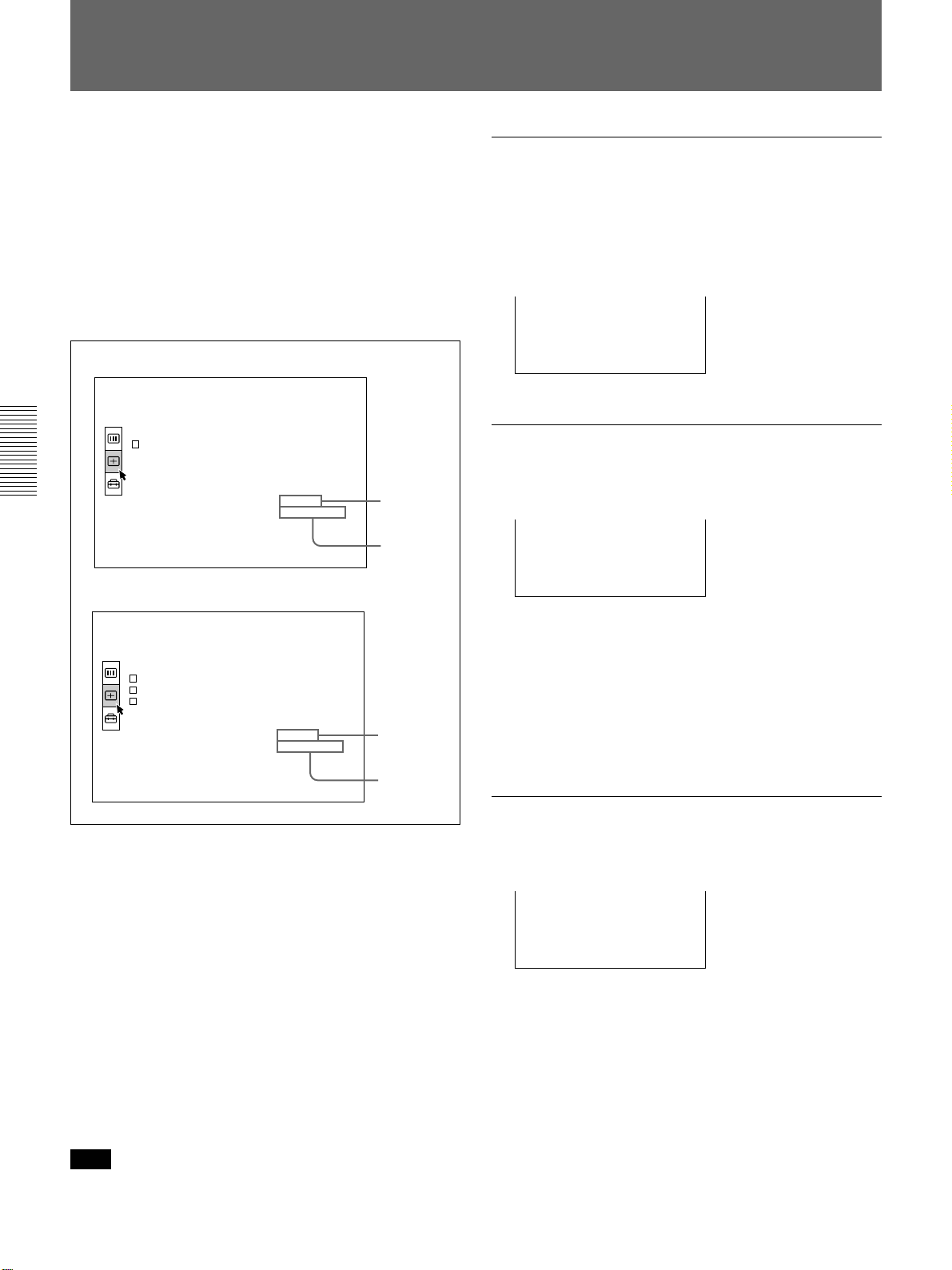
When the video signal is input
INPUT SETTING
ASPECT : 4 : 3
When the RGB signal is input
VIDEO
No . 01
VIDEO/60
Memory No.
Signal type
DOT PHASE
Adjusts the dot phase of the LCD panel and the signal
input from the INPUT A/B connectors. Adjust the
picture further for finer picture after the picture is
adjusted with pressing the APA key.
Adjust the picture to where it looks clearest.
SIZE
Adjusts the horizontal size of picture input from the
INPUT A/B connectors.
INPUT SETTING
DOT PHASE : 7
SIZE H: 1344
SHI FT H: 243 V: 33
I NPUT –A
No . 23
1024X768
Memory No.
Signal type
Operation
1. Select an item
Use the V or v key to select the item, then press the b
or ENTER key.
2. Adjust an item
• When changing the adjustment level:
To increase the number, press the V or b key.
To decrease the number, press the v or B key.
Press the ENTER key to restore the original screen.
• When changing the setting:
Press the V or v key to change the setting.
Press the ENTER or B key to restore the original
screen.
Note
When the HDTV signal is input, the items in the
INPUT SETTING menu cannot be adjusted.
The higher the setting, the larger the horizontal size of
the picture.
The lower the setting, the smaller the horizontal size of
the picture. Adjust the setting according to the dots of
the input signal. For details on the suitable value for
the preset signals, see page 30 (EN).
SHIFT
Adjusts the position of the picture input from the
INPUT A/B connectors.
H adjusts the horizontal position of the picture.
V adjusts the vertical position of the picture.
As the setting for H increases, the picture moves to the
right, and as the setting decreases, the picture moves to
the left.
As the setting for V increases, the picture moves up,
and as the setting decreases, the picture moves down.
Use the B or the b key to adjust the horizontal position
and the V and v key for the vertical position.
28 (EN)
ASPECT
Input signals and adjustable/setting items
Sets the aspect ratio of the picture.
When inputting 16:9 (squeezed) signal from
equipment such as a DVD player, set to 16:9.
INPUT SETTING
ASPECT : 4 : 3
VIDEO
No . 01
VIDEO/60
4:3: When the picture with ratio 4:3 is input.
16:9: When the picture with ratio 16:9 (squeezed) is
input.
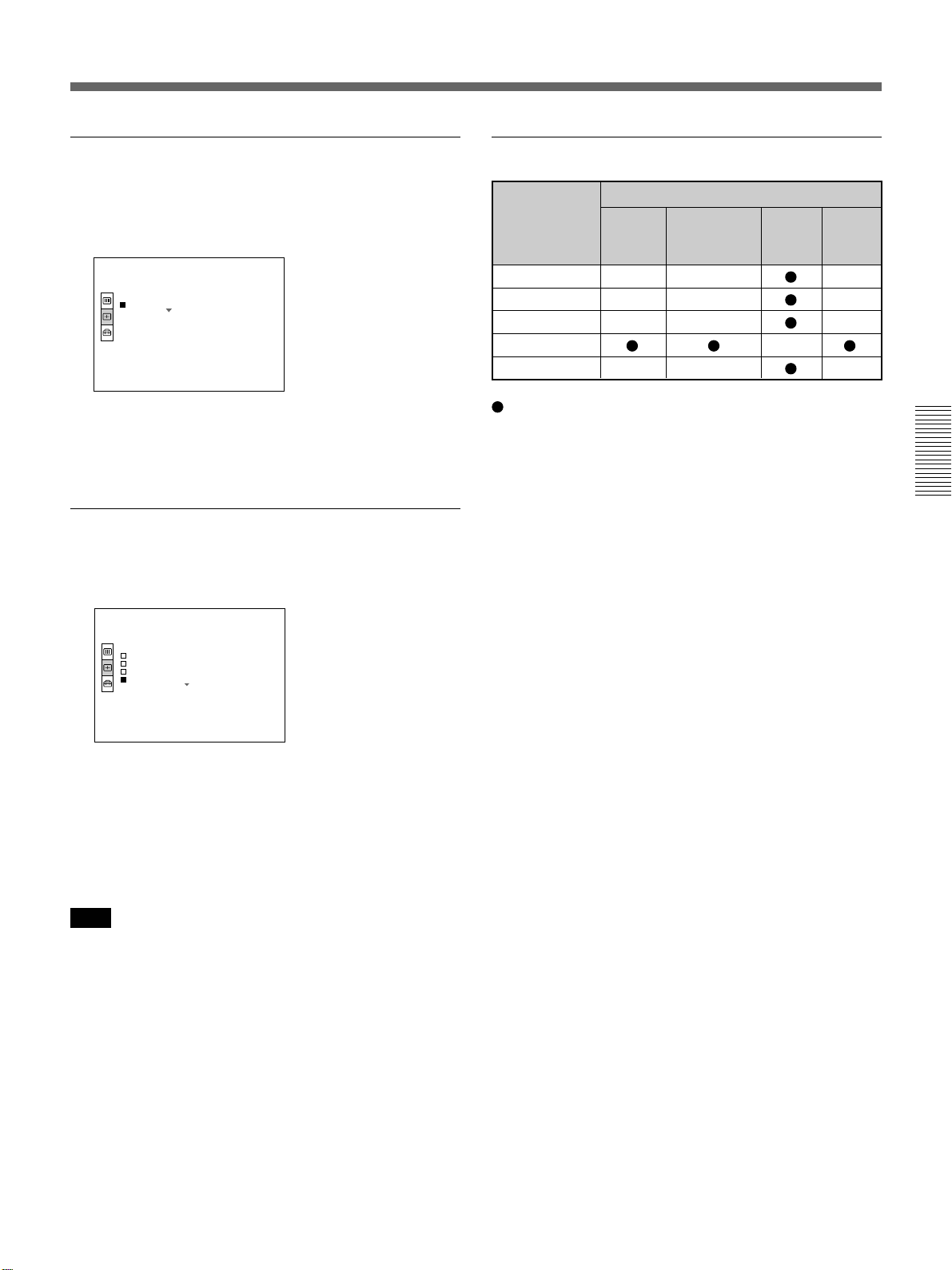
SCAN CONV (Scan converter)
Converts the signal to display the picture according to
the screen size.
INPUT SETTING
DOT PHASE : 7
SIZE H: 1056
SHIFT H : 320 V : 24
SCAN CONV : ON
ON: Displays the picture according to the screen size.
The picture will lose some clarity.
OFF: Displays the picture while matching one pixel
of input picture element to that of the LCD. The
picture will be clear but the picture size will be
smaller.
INPUT–A
No . 17
800X600
Item Input signal
Video or 15k RGB RGB B&W
S video Component
(Y/C)
DOT PHASE – – –
SIZE – – –
SHIFT – – –
ASPECT –
SCAN CONV – – –
: Adjustable/can be set
– : Not adjustable/can not be set
About the preset memory No.
This projector has 38 kinds of preset data for input
signals for each INPUT A/B (the preset memory). The
memory number of the current input signal and the
signal type are displayed when the preset signal is
input. This projector automatically detects the signal
type. When the signal is registered to the preset
memory, a suitable picture is displayed on the screen
according to the signal type. You can adjust the picture
through the INPUT SETTING menu.
This projector also has 20 kinds of user memories for
each INPUT A/B. When an unpreset signal is input for
the first time, memory number is displayed as 00. If
the input signal is adjusted in the INPUT SETTING
menu, the setting via INPUT A is stored under the
memory number 51 to 70, and the setting via INPUT B
is stored under 71 to 90. When more than 20 user
memories are registered for each INPUT A/B, the
newest memory is automatically stored over the oldest
one.
Note
When the XGA or SXGA signal is input, this item will
not be displayed.
29 (EN)
The INPUT SETTING Menu
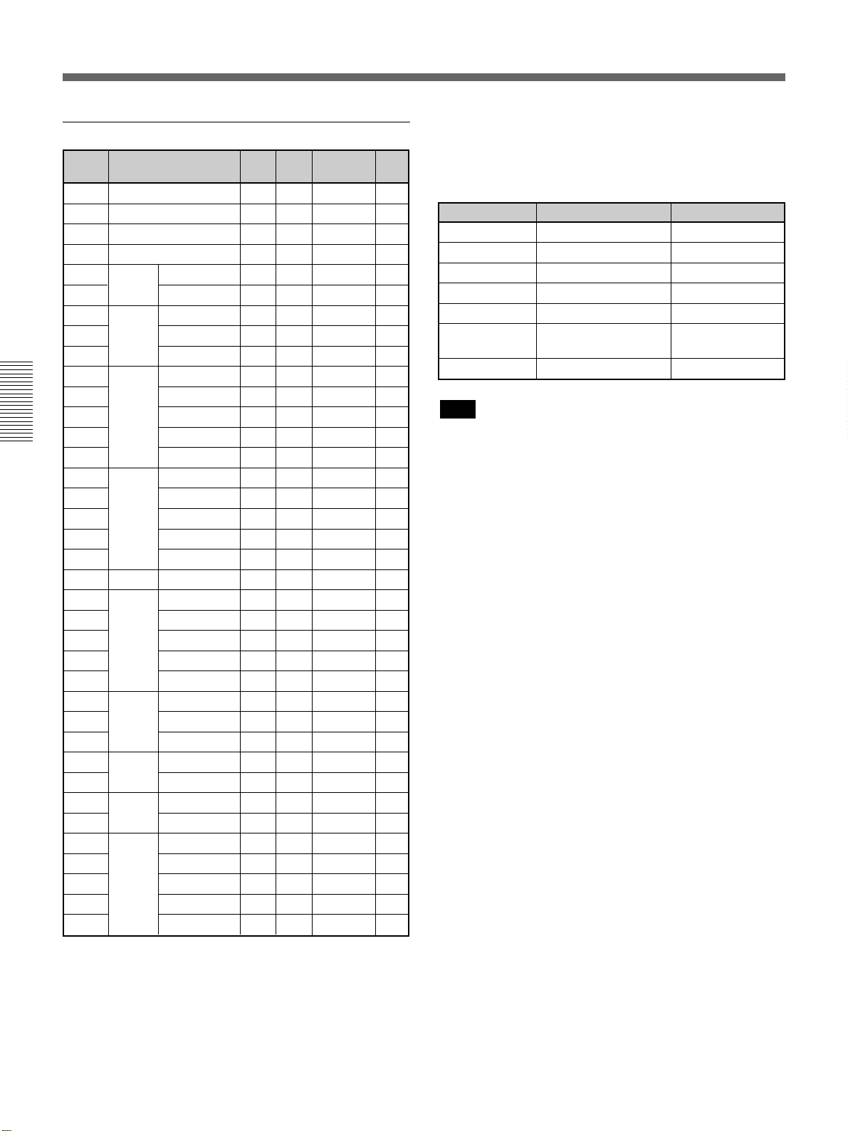
Preset signals
Memory
No. (kHz) (Hz)
1 Video 60 Hz
2 Video 50 Hz
3
4
6
7
8
9 VGA mode 2
10
11
12
13
14
15
16
17
18
19
20
21
22
23
24
25
26
27
28
29
30
31 Sunmicro HI
32
33
34
35 SGI-5
36
37
38
Preset signal
15k RGB/
15k RGB/
640 × 350
640 × 400
640 × 480
800 × 600
832 × 624
1024 × 768
1152 × 864 SXGA VESA 70 Hz
1152 × 900
1280 × 960 SXGA VESA 60 Hz
1280 × 1024
Component 60 Hz
Component 50 Hz
VGA mode 1
VGA VESAa) 85 Hz
PC-9801b) Normal
VGA VESA 85 Hz
VGA mode 3
Macintosh 13”
VGA VESA 72 Hz
VGA VESA 75 Hz
VGA VESA 85 Hz
SVGA VESA 56 Hz
SVGA VESA 60 Hz
SVGA VESA 72 Hz
SVGA VESA 75 Hz
SVGA VESA 85 Hz
Macintosh 16”
XGA VESA 43 Hz
XGA VESA 60 Hz
XGA VESA 70 Hz
XGA VESA 75 Hz
XGA VESA 85 Hz
SXGA VESA 75 Hz
SXGA VESA 85 Hz
Sunmicro LO
SXGA VESA 75 Hz
SXGA VESA 43 Hz
SXGA VESA 60 Hz
SXGA VESA 75 Hz
SXGA VESA 85 Hz
fH fV
15.734 59.940 H-neg V-neg
15.625 50.000 H-neg V-neg
15.734 59.940 H-neg V-neg
15.625 50.000 H-neg V-neg
31.469 70.086 H-pos V-neg 800
37.861 85.080 H-pos V-neg 832
24.823 56.416 H-neg V-neg 848
31.469 70.086 H-neg V-pos 800
37.861 85.080 H-neg V-pos 832
31.469 59.940 H-neg V-neg 800
35.000 66.667 H-neg V-neg 864
37.861 72.809 H-neg V-neg 832
37.500 75.000 H-neg V-neg 840
43.269 85.008 H-neg V-neg 832
35.156 56.250 H-pos V-pos 1024
37.879 60.317 H-pos V-pos 1056
48.077 72.188 H-pos V-pos 1040
46.875 75.000 H-pos V-pos 1056
53.674 85.061 H-pos V-pos 1048
49.724 74.550 H-neg V-neg 1152
35.522 43.479 H-pos V-pos 1264
48.363 60.004 H-neg V-neg 1344
56.476 70.069 H-neg V-neg 1328
60.023 75.029 H-pos V-pos 1312
68.677 84.997 H-pos V-pos 1376
63.995 70.016 H-pos V-pos 1472
67.500 75.000 H-pos V-pos 1600
77.487 85.057 H-pos V-pos 1568
61.795 65.960 H-neg V-neg 1504
71.713 76.047 H-neg V-neg 1472
60.000 60.000 H-pos V-pos 1800
75.000 75.000 H-pos V-pos 1728
46.433 43.436 H-pos V-pos 1696
53.316 50.062 H-neg V-neg 1680
63.974 60.013 H-pos V-pos 1696
79.976 75.025 H-pos V-pos 1688
91.146 85.024 H-pos V-pos 1728
Sync
SIZE
Since the data is recalled from the preset memory
about the following signals, you can use these preset
data by adjusting SIZE. Make fine adjustment by
adjusting SHIFT.
Signal Memory No. SIZE
Super Mac-2 23 1312
SGI-1 23 1320
Macintosh 19” 25 1328
Macintosh 21” 28 1456
Sony News 36 1708
PC-9821 36 1600
1280 × 1024
WS Sunmicro 37 1664
Note
When the aspect ratio of input signal is other than 4:3,
a part of the screen is displayed in black.
a) VESA is a registered trademark of Video Electronics
Standard Association.
b) PC-98 is a registered trademark of NEC Corporation.
30 (EN)
 Loading...