

Sony VPL-VZ1000ES Quick Reference Guide
4-693-528-11 (1)
Video Projector
Quick Reference Manual ___ US
Guide de reference rapide _ FR
Printed in Japan
VPL-VZ1000
© 2017 Sony Corporation
About the Quick Reference Manual
This Quick Reference Manual explains the installation and basic operations for projecting pictures.
Before operating the unit, please read this manual thoroughly and retain it for future reference.
Refer to “About Indicators,” “Cleaning the Air Filter,” and “Cleaning,” as necessary.
For details on the operations, refer to the Operating Instructions contained in the supplied CD-ROM.
Step 1
Step 2
Step 3
Step 4
Step 5
Error Handling
Installing the Unit................................................... Page 3
Adjusting .................................................................. Page 7
Connecting the Unit ............................................ Page 10
Attaching the Covers.......................................... Page 11
Projecting............................................................... Page 13
About Indicators....................................................................... Page 14
Maintenance
Using the CD-ROM manual
The manual can be read on a computer with Adobe
Reader installed.
You can download Adobe Reader free from the Adobe
website.
Cleaning the Air Filter..............................................................Page 15
Cleaning....................................................................................Page 15
1 Open the index.html file in the CD-ROM.
2 Select and click on the manual that you want to read.
Note
If you have lost or damaged the CD-ROM, you can purchase a new
one from your Sony dealer or Sony service counter.
Adobe and Adobe Reader are trademarks of Adobe Systems
Incorporated in the United States and/or other countries.
US
2
About the Quick Reference Manual
Step 1
Installing the Unit
Checking the Supplied Accessories
Check the carton to make sure it contains the following
items:
• Remote control RM-PJ28 (1)
• Size AA (R6) manganese batteries (2)
• AC power cord (1)
• Plug holder (1)
• Top cover (1)
• Side covers (2)
• Straps for side covers (2)
• Rivets for side covers (2)
• Cleaning cloth (1)
• Quick Reference Manual (this manual) (1)
• Safety Regulations (1)
• Operating Instructions (CD-ROM) (1)
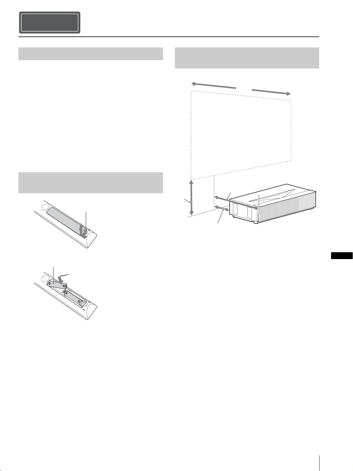
Inserting the Batteries into the
Remote Control
Push and slide to open.
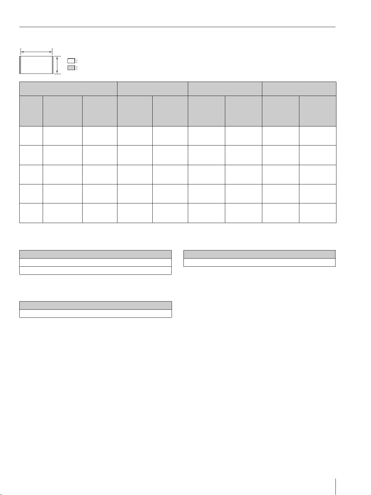
Installation Distance and Projection
Image Size
W
L2
H
Insert the batteries E side first.
Caution about handling the remote control
• Handle the remote control with care. Do not drop or step
on it, or spill liquid of any kind onto it.
• Do not place the remote control in a location near a heat
source, a place subject to direct sunlight, or a damp
room.
L1
L1: Distance from a projection surface to the rear of the
unit
L2: Distance from a projection surface to the front of the
unit
H: Distance from the installation surface to the bottom of
the screen
W: Horizontal width of the screen
US
Installing the Unit
US
3
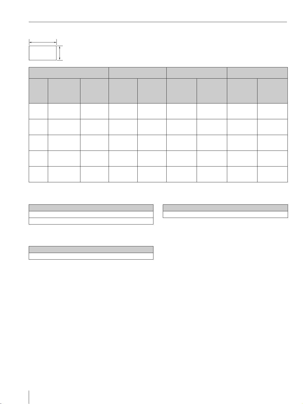
When projecting in 1.90:1 (Native Full Display 17:9) format
1.90
1
Projection image size Installation distance
From a
Diagonal
(D)
84-inch
(2.14 m)
95-inch
(2.40 m)
105-inch
(2.67 m)
116-inch
(2.94 m)
126-inch
(3.21 m)
Width × Height
1.89 m × 1.00 m
(74 inches × 39
inches)
2.13 m × 1.12 m
(84 inches × 44
inches)
2.36 m × 1.24 m
(93 inches × 49
inches)
2.60 m × 1.37 m
(102 inches × 54
inches)
2.84 m × 1.49 m
(112 inches × 59
inches)
Bottom
height (H)
39.0 cm
(15.3 inches)
41.8 cm
(16.5 inches)
44.7 cm
(17.6 inches)
47.6 cm
(18.7 inches)
50.4 cm
(19.9 inches)
projection
surface to the
rear of the unit
(L1)
5.0 cm
(2.0 inches)
10.2 cm
(4.0 inches)
15.5 cm
(6.1 inches)
20.7 cm
(8.2 inches)
26.0 cm
(10.2 inches)
surface to the
Formula 1 (calculates an installation distance from a
projection image size)
Unit: cm (inches)
Projection image size
L1 = 0.2219 × W - 36.9398 (L1 = 0.2219 × W - 14.5432)
L2 = 0.2219 × W + 10.0602 (L2 = 0.2219 × W + 3.9607)
From a
projection
front of the
unit (L2)
52.0 cm
(20.5 inches)
57.2 cm
(22.5 inches)
62.5 cm
(24.6 inches)
67.7 cm
(26.7 inches)
73.0 cm
(28.7 inches)
Adjustment amount of picture
Horizontal
direction
+/_5.3 cm
(+/_2.1 inches)
+/_6.0 cm
(+/_2.4 inches)
+/_6.6 cm
(+/_2.6 inches)
+/_7.3 cm
(+/_2.9 inches)
+/_8.0 cm
(+/_3.1 inches)
shift
Vertical
direction
+/_6.0 cm
(+/_2.4 inches)
+/_6.7 cm
(+/_2.6 inches)
+/_7.5 cm
(+/_2.9 inches)
+/_8.2 cm
(+/_3.2 inches)
+/_9.0 cm
(+/_3.5 inches)
Adjustment amount of picture
Horizontal
direction
+/_1.9 cm
(+/_0.7 inches)
+/_2.1 cm
(+/_0.8 inches)
+/_2.4 cm
(+/_0.9 inches)
+/_2.6 cm
(+/_0.9 inches)
+/_2.8 cm
(+/_1.1 inches)
size
Vertical
direction
+/_1.0 cm
(+/_0.4 inches)
+/_1.1 cm
(+/_0.4 inches)
+/_1.2 cm
(+/_0.5 inches)
+/_1.4 cm
(+/_0.6 inches)
+/_1.5 cm
(+/_0.6 inches)
Formula 3 (calculates a distance from the installation
surface to the bottom of a projection image)
Unit: cm (inches)
Projection image size
H = 0.1213 × W + 16.0372 (H = 0.1213 × W + 6.3139)
Formula 2 (calculates a projection image size from an
installation distance)
Unit: cm (inches)
From a projection surface to the rear of the unit
W = 4.5069 × L1 + 166.4916 (W = 4.5069 × L1 + 65.5479)
US
4
Installing the Unit
When projecting in 1.78:1 (16:9) format
1.78
Video display area
Projection area
Bottom
height (H)
39.0 cm
(15.3 inches)
41.8 cm
(16.5 inches)
44.7 cm
(17.6 inches)
47.6 cm
(18.7 inches)
50.4 cm
(19.9 inches)
From a
projection
surface to the
rear of the unit
(L1)
5.0 cm
(2.0 inches)
10.2 cm
(4.0 inches)
15.5 cm
(6.1 inches)
20.7 cm
(8.2 inches)
26.0 cm
(10.2 inches)
Diagonal
(D)
80-inch
(2.03 m)
90-inch
(2.29 m)
100-inch
(2.54 m)
110-inch
(2.79 m)
120-inch
(3.05 m)
1
Projection image size Installation distance
Width × Height
1.77 m × 1.00 m
(70 inches × 39
inches)
1.99 m × 1.12 m
(78 inches × 44
inches)
2.22 m × 1.24 m
(87 inches × 49
inches)
2.44 m × 1.37 m
(96 inches × 54
inches)
2.66 m × 1.49 m
(105 inches × 59
inches)
Formula 1 (calculates an installation distance from a
projection image size)
Unit: cm (inches)
Projection image size
L1 = 0.2368 × W - 36.9638 (L1 = 0.2368 × W - 14.5527)
L2 = 0.2368 × W + 10.0362 (L2 = 0.2368 × W + 3.9512)
From a
projection
surface to the
front of the
unit (L2)
52.0 cm
(20.5 inches)
57.2 cm
(22.5 inches)
62.5 cm
(24.6 inches)
67.7 cm
(26.7 inches)
73.0 cm
(28.7 inches)
Adjustment amount of picture
Horizontal
direction
+/_5.3 cm
(+/_2.1 inches)
+/_6.0 cm
(+/_2.4 inches)
+/_6.6 cm
(+/_2.6 inches)
+/_7.3 cm
(+/_2.9 inches)
+/_8.0 cm
(+/_3.1 inches)
shift
Vertical
direction
+/_6.0 cm
(+/_2.4 inches)
+/_6.7 cm
(+/_2.6 inches)
+/_7.5 cm
(+/_2.9 inches)
+/_8.2 cm
(+/_3.2 inches)
+/_9.0 cm
(+/_3.5 inches)
Adjustment amount of picture
Horizontal
direction
+/_1.8 cm
(+/_0.7 inches)
+/_2.0 cm
(+/_0.8 inches)
+/_2.2 cm
(+/_0.9 inches)
+/_2.4 cm
(+/_0.9 inches)
+/_2.7 cm
(+/_1.1 inches)
size
Vertical
direction
+/_1.0 cm
(+/_0.4 inches)
+/_1.1 cm
(+/_0.4 inches)
+/_1.2 cm
(+/_0.5 inches)
+/_1.4 cm
(+/_0.6 inches)
+/_1.5 cm
(+/_0.6 inches)
Formula 3 (calculates a distance from the installation
surface to the bottom of a projection image)
Unit: cm (inches)
Projection image size
H = 0.1295 × W + 16.0240 (H = 0.1295 × W + 6.3087)
Formula 2 (calculates a projection image size from an
installation distance)
Unit: cm (inches)
From a projection surface to the rear of the unit
W = 4.2226 × L1 + 156.0908 (W = 4.2226 × L1 + 61.4531)
Installing the Unit
US
5
Installing the Unit
The installation distance between the unit and a projection
surface varies depending on the projection size. Install this
unit so that it fits the desired projection size.
For customers
CAUTION
When mounting the projector to the ceiling or moving it to
a different location, do not do so by yourself.
For dealers
• When installing the unit on a ceiling, be sure to read
“Safety precautions for installing the unit on a ceiling” in
the Safety Regulations (supplied separately).
• When installing the unit on a ceiling, remove the feet
first, and follow the instructions below.
Screw diameter: M10
Fixing positions: 5 positions
Insertion length of screws: 10 mm - 50 mm (
13
/32 2 inches)
Recommended tightening torque: 1.3 - 1.5 N•m
1 Position the unit so that the unit is parallel to the
projection surface.
4 Plug the AC power cord into a wall outlet.
The unit goes into standby mode.
Tip
After connecting the AC power cord to the unit, the LED
indicator may blink.
You may not be able to control the unit while the indicator is
blinking, but this is not a malfunction. Wait until it stops
blinking.
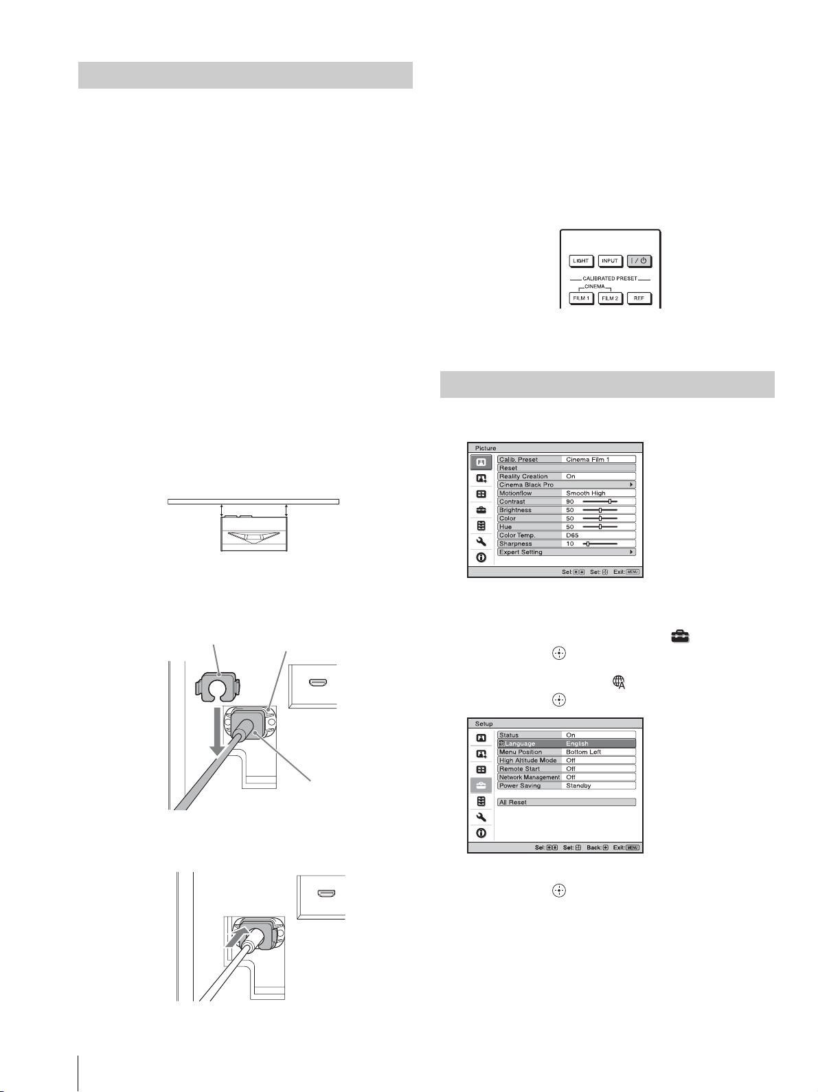
5 Press the ?/1 (On/Standby) button to turn on the unit.
The LED indicator lights in white.
Selecting the Menu Language
1 Press MENU to display the menu.
Top view
Projection surface
ab
a = b
2 Plug the AC power cord into the AC IN socket, then
attach the plug holder to the AC power cord.
Plug holder (supplied)
AC IN socket
AC power cord
(supplied)
3 Slide the plug holder over the AC power cord to fix to
the unit.
2 Select the menu language.
a Press M/m to select the Setup menu, then
press , or .
b Press M/m to select “ Language,” then
press , or .
Setup
Status
Language
Menu Position
High Altitude Mode
Remote Start
Network Management
Power Saving
All Reset
On
English
Bottom Left
Off
Off
Off
Standby
US
6
c Press M/m/</, to select a language, then
press , or .
3 Press MENU to turn off the menu window.
Installing the Unit
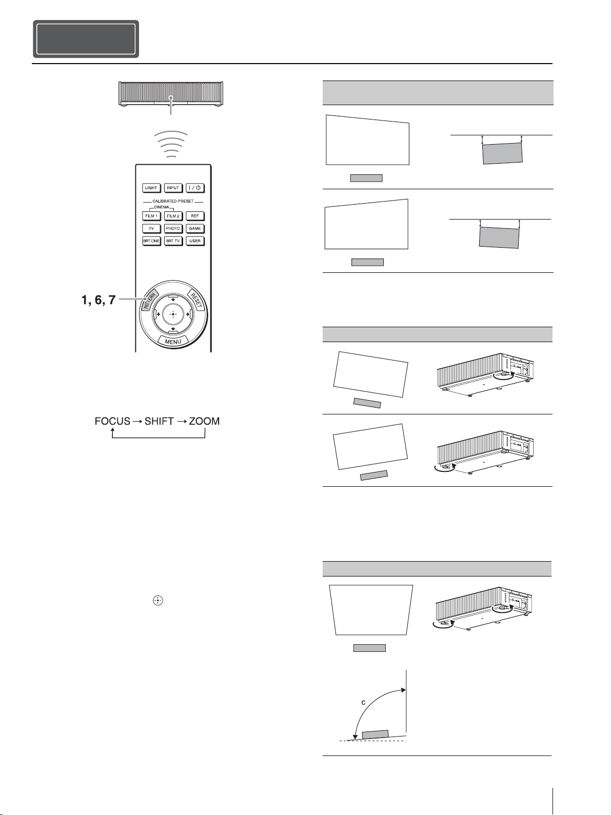
Step 2
Adjusting
Remote control detector
Tip
When adjusting the lens, each time you press the PATTERN button
of the remote control or the LENS button on the unit, the lens
adjustment function switches as follows.
Image distortion Installation state to the projection surface
(Top view)
a
a
b
a > b
b
a < b
3 Check if the lower side of the picture is horizontal.
If not, use the left/right feet (adjustable) to keep the
unit level. For details on adjusting the feet, see page 9.
Image distortion Feet adjustment
1 Press the PATTERN button to display the Lens Focus
adjustment window, and adjust the focus of the picture
by pressing the M/m/</, buttons.
Tips
• The factory default for focus has been adjusted to the 100inch screen. Make fine adjustments according to the screen
size and installing position.
• Adjust by checking the entire test pattern. The amplitude of
the pattern focus on the top of the picture becomes large with
the ultra short focus projector.
• If you press the RESET button on the remote control while
the Lens Focus adjustment window is displayed, the focus
setting returns to the factory default.
• Whenever you press the button, the test pattern
disappears.
2 Check if the upper side and lower side of the picture
are parallel.
If not, install the unit in a position parallel to the
projection surface (a=b).
4 Check if the left side and right side of the picture are
vertical.
If not, use the feet (adjustable) to keep the unit vertical
to the projection surface. For details on adjusting the
feet, see page 9.
Image distortion Feet adjustment
Side view
c > 90°
Adjusting
US
7
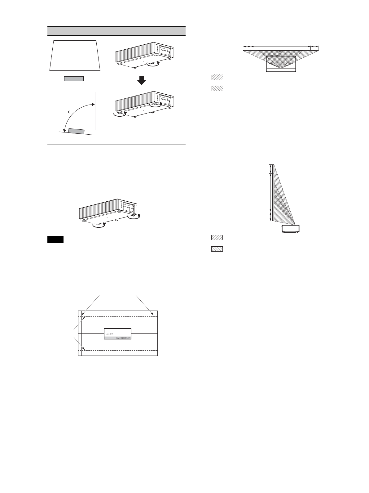
Image distortion Feet adjustment
Adjust the foot
near the rear
side so that it is
longer.
Side view
Top view
3%* 3%*1 screen width
: Picture position when moving the picture to the left at
maximum
: Picture position when moving the picture to the right at
maximum
Adjust the
height with the
feet near the
front side.
c < 90°
If the frame of the projection surface is rectangle and
parallel to the floor, adjustment is completed.
Tip
If the picture remains distorted, repeat step 2 and 3.
5 Adjust the feet for preventing backlash to the floor.
Note
The picture may be distorted if you turn the feet for preventing
backlash too much.
6 Press the PATTERN button to display the Lens Shift
adjustment window, and adjust the picture position by
pressing the M/m/</, buttons.
1.78:1 (16:9)
* For 17:9 display, the range of movement will be +/
_
2.8%.
To adjust the vertical position
When pressing the M/m button, the picture projected
on the screen moves up or down by a maximum of 6%
of the screen height from the center of the lens.
Side view
6%
1 screen
height
6%
: Picture position when moving the picture upward at
maximum
: Picture position when moving the picture downward at
maximum
7 Press the PATTERN button again to display the Lens
Zoom adjustment window. Then adjust the size of the
picture by pressing the M/m/</, buttons.
To make the picture larger, press M/,.
To make the picture smaller, press m/<.
US
8
2.35:1
The dashed lines show the screen sizes of
each aspect ratio.
Tip
If you press the RESET button on the remote control while the
Lens Shift adjustment window is displayed, the picture
position returns to the center of the lens (factory default
position).
To adjust the horizontal position
When pressing the </, button, the picture
projected on the screen moves right or left by a
maximum of 3% of the screen width from the center
of the lens.
Adjusting
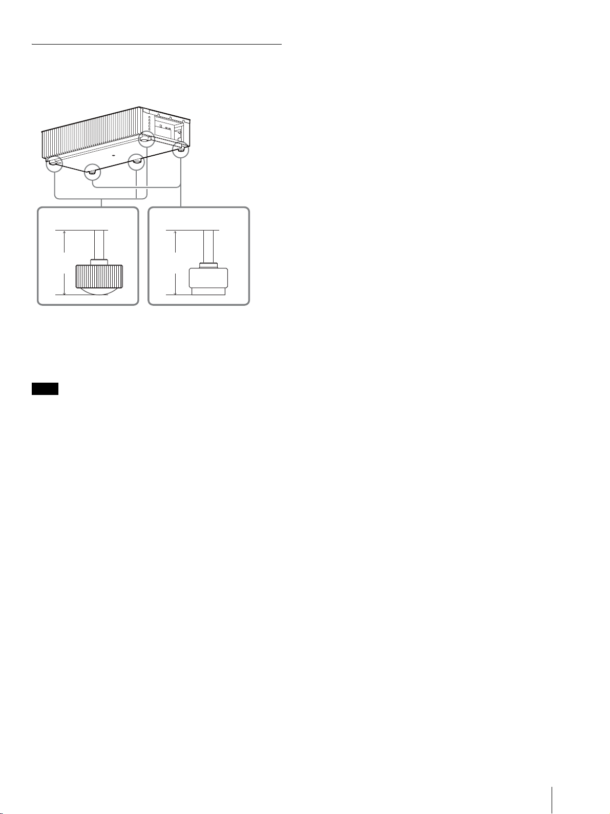
Adjusting the height of the feet
You can adjust the height and tilt of the unit using the three
feet at the bottom of the unit, and prevent backlash of the
unit using the two feet.
Foot for adjusting
the tilt
Foot
height
Foot for preventing
backlash
Foot
height
Tips
• The feet for adjusting the tilt can be adjusted by 1.5 mm with every
full turn.
• The left and right feet near the rear side can be used to prevent the
backlash. You can adjust these feet to the same height as the feet
for adjusting the tilt.
Notes
• Be careful not to get your finger caught when turning the feet for
adjusting the tilt or feet for preventing backlash.
• You can adjust the foot height up to 20 mm. If the foot height is
more than 30 mm, the foot may come off and the unit may drop
causing an injury.
Adjusting
US
9
 Loading...