

Sony VPL-VW1000ES Operating Instruction
© 2011 Sony Corporation
Printed in Japan
Operating Instructions
Before operating the unit, please read this manual thoroughly and retain it for
future reference.
VPL-VW1000ES
4-414-629-14 (1)
Video Projector

WARNING
- Consult the dealer or an experienced
radio/TV technician for help.
To reduce the risk of fire or
electric shock, do not expose
this apparatus to rain or
moisture.
To avoid electrical shock, do
not open the cabinet. Refer
servicing to qualified
personnel only.
THIS APPARATUS MUST BE
EARTHED.
For the customers in the U.S.A. and
Canada
WARNING:
Using this unit at a voltage other than 120 V
may require the use of a different line cord or
attachment plug, or both. To reduce the risk
of fire or electric shock, refer servicing to
qualified service personnel.
For the customers in the U.S.A.
This equipment has been tested and found to
comply with the limits for a Class B digital
device, pursuant to part 15 of the FCC Rules.
These limits are designed to provide
reasonable protection against harmful
interference in a residential installation. This
equipment generates, uses and can radiate
radio frequency energy and, if not installed
and used in accordance with the instructions,
may cause harmful interference to radio
communications. However, there is no
guarantee that interference will not occur in a
particular installation. If this equipment does
cause harmful interference to radio or
television reception, which can be determined
by turning the equipment off and on, the user
is encouraged to try to correct the interference
by one or more of the following measures:
- Reorient or relocate the receiving antenna.
- Increase the separation between the
equipment and receiver.
- Connect the equipment into an outlet on a
circuit different from that to which the
receiver is connected.
You are cautioned that any changes or
modifications not expressly approved in this
manual could void your authority to operate
this equipment.
All interface cables used to connect
peripherals must be shielded in order to
comply with the limits for a digital device
pursuant to Subpart B of part 15 of FCC
Rules.
If you have any questions about this product,
you may call;
Sony Customer Information Service Center
1-800-222-7669 or http://www.sony.com/
Declaration of Conformity
Trade Name: SONY
Model: VPL-VW1000ES
Responsible party: Sony Electronics Inc.
Address: 16530 Via Esprillo,
San Diego, CA 92127
U.S.A.
Telephone Number:858-942-2230
This device complies with part 15 of the
FCC Rules. Operation is subject to the
following two conditions: (1) This device
may not cause harmful interference, and
(2) this device must accept any interference
received, including interference that may
cause undesired operation.
For the customers in Canada
This Class B digital apparatus complies with
Canadian ICES-003.
For the customers in Europe
This product has been manufactured by or
on behalf of Sony Corporation, 1-7-1 Konan
Minato-ku Tokyo, 108-0075 Japan.
Inquiries related to product compliance
based on European Union legislation shall
be addressed to the authorized
representative, Sony Deutschland GmbH,
Hedelfinger Strasse 61, 70327 Stuttgart,
Germany. For any service or guarantee
matters, please refer to the addresses
2

provided in the separate service or guarantee
documents.
WARNUNG
AVERTISSEMENT
Afin de réduire les risques
d’incendie ou d’électrocution,
ne pas exposer cet appareil à
la pluie ou à l’humidité.
Afin d’écarter tout risque
d’électrocution, garder le
coffret fermé. Ne confier
l’entretien de l’appareil qu’à
un personnel qualifié.
CET APPAREIL DOIT ÊTRE
RELIÉ À LA TERRE.
Pour les clients au Canada
Cet appareil numérique de la classe B est
conforme à la norme NMB-003 du Canada.
Pour les clients en Europe
Ce produit a été fabriqué par ou pour le
compte de Sony Corporation, 1-7-1 Konan
Minato-ku Tokyo, 108-0075 Japon. Toutes
les questions relatives à la conformité des
produits basées sur la législation européenne
doivent être adressées à son représentant,
Sony Deutschland GmbH, Hedelfinger
Strasse 61, 70327 Stuttgart, Allemagne.
Pour toute question relative au Service
Après-Vente ou à la Garantie, merci de bien
vouloir vous référer aux coordonnées qui
vous sont communiquées dans les
documents « Service (SAV) » ou Garantie.
Um die Gefahr von Bränden
oder elektrischen Schlägen zu
verringern, darf dieses Gerät
nicht Regen oder Feuchtigkeit
ausgesetzt werden.
Um einen elektrischen Schlag
zu vermeiden, darf das
Gehäuse nicht geöffnet
werden. Überlassen Sie
Wartungsarbeiten stets nur
qualifiziertem Fachpersonal.
DIESES GERÄT MUSS
GEERDET WERDEN.
Für Kunden in Europa
Dieses Produkt wurde von oder für Sony
Corporation, 1-7-1 Konan Minato-ku Tokio,
108-0075 Japan hergestellt.
Bei Fragen zur Produktkonformität auf
Grundlage der Gesetzgebung der
Europäischen Union kontaktieren Sie bitte
den Bevollmächtigten Sony Deutschland
GmbH, Hedelfinger Strasse 61, 70327
Stuttgart, Deutschland. Für Kundendienst
oder Garantieangelegenheiten wenden Sie
sich bitte an die in den Kundendienst- oder
Garantiedokumenten genannten Adressen.
For kundene i Norge
Dette utstyret kan kobles til et ITstrømfordelingssystem.
Für Kunden in Deutschland
Entsorgungshinweis: Bitte werfen Sie nur
entladene Batterien in die Sammelboxen
beim Handel oder den Kommunen. Entladen
sind Batterien in der Regel dann, wenn das
Gerät abschaltet und signalisiert „Batterie
leer“ oder nach längerer Gebrauchsdauer der
Batterien „nicht mehr einwandfrei
funktioniert“. Um sicherzugehen, kleben Sie
die Batteriepole z.B. mit einem
Klebestreifen ab oder geben Sie die
Batterien einzeln in einen Plastikbeutel.
3
For the customers in Taiwan only
equipamento, disponha-o em um ponto de
coleta na Rede Autorizada Sony ou nas lojas
Sony, de forma a garantir o tratamento
adequado da bateria.
Note on use of the USB charging
AC power adaptor AC-UD10
For the Customers in Brazil only
DESCARTE DE PILHAS E BATERIAS
Pilhas e Baterias não recarregáveis
Atenção:
Verifique as instruções de uso do aparelho
certificando-se de que as polaridades (+) e
(-) estão no sentido indicado. As pilhas
poderão vazar ou explodir se as polaridades
forem invertidas, expostas ao fogo,
desmontadas ou recarregadas.
Evite misturar com pilhas de outro tipo ou
com pilhas usadas, transportá-las ou
armazená-las soltas, pois aumenta o risco de
vazamento.
Retire as pilhas caso o aparelho não esteja
sendo utilizado, para evitar possíveis danos
na eventualidade de ocorrer vazamento.
As pilhas devem ser armazenadas em local
seco e ventilado.
No caso de vazamento da pilha, evite o
contato com a mesma.
Lave qualquer parte do corpo afetado com
água abundante.
Ocorrendo irritação, procure auxílio médico.
Não remova o invólucro da pilha.
Mantenha fora do alcance das crianças. Em
caso de ingestão procure auxílio médico
imediatamente.
For the customer in the U.S.A.
The following FCC statement applies only
to the version of this model manufactured
for safe in the USA.
Other versions may not comply with FCC
technical regulations.
This device complies with part 15 of the
FCC Rules. Operation is subject to the
following two conditions: (1) This device
may not cause harmful interference, and (2)
this device must accept any interference
received, including interference that may
cause undesired operation.
DESCARTE DE PILHAS E BATERIAS
Este produto contém bateria de alimentação
integrada (não removível pelo usuário) que
só deve ser substituída por profissionais
qualificados. Ao fim da vida útil do
4

Table of Contents
Precautions .........................................7
Location of Controls
Front/Right Side .................................8
Rear/Bottom .......................................9
Remote Control ................................10
Connections and
Preparations
Unpacking ........................................11
Inserting the Batteries into the Remote
Control .............................................11
Connecting the AC Power Cord .......12
Preparation 1: Installing the Unit .....13
Before Setting Up the Unit ......... 13
Notes on Use ..............................14
Installing the Unit .......................16
Preparation 2: Adjusting the Picture
Position .............................................17
Preparation 3: Connecting the
Unit ...................................................22
Connecting to a VCR .................22
Connecting to a Computer ..........24
Connecting to a 3D Sync
Transmitter .................................25
Preparation 4: Selecting the Menu
Language ..........................................26
Turning Off the Power ............... 28
Watching 3D Video Images ............ 28
Using the 3D Glasses ................. 29
Charging the 3D Glasses ............ 31
Using the Picture Position ............... 32
Selecting the Aspect Ratio According to
the Video Signal .............................. 34
Selecting the Picture Viewing
Mode ................................................ 37
Using the Supplied Software to Adjust
the Picture Quality
(ImageDirector3) ............................. 38
Using the Menus
Operation through the Menus .......... 39
Picture Menu ................................... 41
Screen Menu .................................... 47
Setup Menu ...................................... 50
Function Menu ................................. 52
Installation Menu ............................. 55
Information Menu ............................ 59
About the Preset Memory No. ... 59
Using Network Features
Displaying the Control Window of the
Unit with a Web Browser ................ 61
Operating the Control Window ....... 62
Projecting
Projecting the Picture .......................27
Switching the Page ..................... 62
Setting the Access Limitation .... 62
Confirming the Information
Regarding the Unit ..................... 62
5

Operating the Unit from a
Computer ....................................62
Using the E-mail Report
Function ...................................... 63
Others
About the Control for HDMI ........... 65
About DCI specification .................. 66
About the x.v.Color ......................... 66
About the simulated 3D feature ....... 66
Troubleshooting ...............................67
Warning Indicators .....................70
Message Lists ............................. 71
Replacing the Lamp and Cleaning the
Ventilation Holes (intake) ................ 73
Cleaning and the Screen of the
Projector ...........................................76
Specifications ................................... 77
Preset Signals .............................79
Input Signals and Adjustable/
Setting Items ...............................82
Compatible 3D Signals ..............84
3D Signals and Adjustable/Setting
Items ......................................... 84
Aspect Mode .............................. 85
Storage Conditions of Adjustable/
Setting Items ...............................86
Projection Distance and Lens Shift
Range ...............................................89
Dimensions ......................................93
Index ...............................................96
6
Trademark Information
“PS3” is a registered trademark of Sony
Computer Entertainment Inc.
The terms HDMI and HDMI HighDefinition Multimedia Interface, and the
HDMI Logo are trademarks or registered
trademarks of HDMI Licensing LLC in the
United States and other countries.
“Blu-ray” and “Blu-ray Disc” are trademarks
of Blu-ray Disc Association.
..........................................................................
Control for HDMI is an HDMI standard mutual
control function which uses the HDMI CEC
(Consumer Electronics Control) specification.
This projector supports DeepColor, x.v.Color,
LipSync, 3D signal and computer input signal
of HDMI standards. It also supports HDCP.

Precautions
Safety precautions when using 3D
Glasses
On safety
• Check that the operating voltage of your
unit is identical with the voltage of your
local power supply.
• Should any liquid or solid object fall into
the cabinet, unplug the unit and have it
checked by qualified personnel before
operating it further.
• Unplug the unit from the wall outlet if it is
not to be used for several days.
• To disconnect the cord, pull it out by the
plug. Never pull the cord itself.
• The wall outlet should be near the unit and
easily accessible.
• The unit is not disconnected to the AC
power source (mains) as long as it is
connected to the wall outlet, even if the
unit itself has been turned off.
• Do not look into the lens while the lamp is
on.
• Do not place your hand or objects near the
ventilation holes. The air coming out is
hot.
On preventing internal heat buildup
After you turn off the power with the ?/1
(ON/STANDBY) button, do not disconnect
the unit from the wall outlet while the
cooling fan is still running.
Warning
• Do not put the 3D Glasses in a fire.
• Do not disassemble the 3D Glasses.
• Do not use, charge, store, or leave the 3D
Glasses near a fire, or in places with a high
temperature, e.g., in direct sunlight, or in
sun-heated cars.
• Use only the supplied USB cable.
• Do not charge the 3D Glasses with
anything other than the supplied USB
charging AC power adaptor.
• Do not allow water or foreign material to
enter the 3D Glasses.
Safety precautions
• Use only the type of 3D glasses included
with this unit. You should only use the 3D
glasses for watching 3D video images. Do
not use the 3D Glasses with other
equipment, such as TV.
• If you observe flickering or flashing, turn
off the lighting in the room.
• Not for use by children without proper
adult supervision.
• Be careful not to pinch your fingers in
hinges of the 3D glasses when bending the
temple frames.
• Do not drop or modify these 3D glasses.
• If these glasses are broken, keep broken
pieces away from your mouth or eyes.
Caution
This unit is equipped with ventilation holes
(intake) and ventilation holes (exhaust). Do
not block or place anything near these holes,
or internal heat build-up may occur, causing
picture degradation or damage to the unit.
On repacking
Save the original shipping carton and
packing material; they will come in handy if
you ever have to ship your unit. For
maximum protection, repack your unit as it
was originally packed at the factory.
7
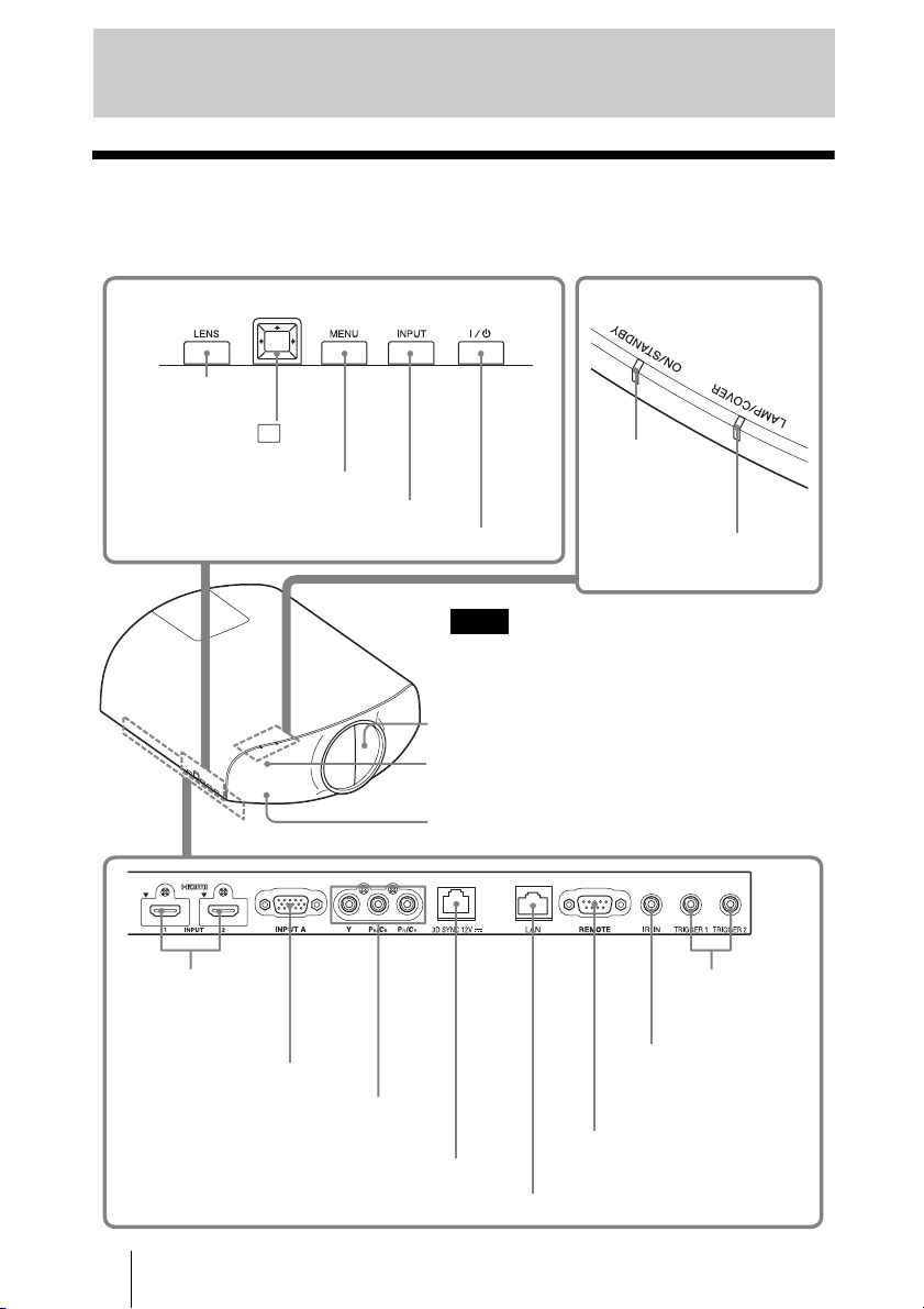
Location of Controls
Front/Right Side
You can use the buttons on the control panel with the same names as those on the remote
control to operate the unit.
Control panel
LENS button
(1 page 17)
M/m/</, (arrow)/ (enter)
button (1 page 39)
MENU button (1 page 39)
INPUT button (1 page 27)
?/1 (ON/STANDBY) button (1 page 18)
Note
While the ON/STANDBY indicator lights in orange,
the power saving mode is on. (1 page 51)
ON/STANDBY
indicator
(1 page 18)
LAMP/COVER indicator
(1 page 70)
HDMI 1/2 connector
(1 page 22)
INPUT A connector (1 page 24)
Y PB/CB PR/CR connector (phono type)
(1 page 23)
3D SYNC connector (1 page 25)
8
Lens protector
3D Sync Transmitter area
Remote control detection area
LAN connector (1 page 61)
TRIGGER 1/
TRIGGER 2
connector (1
page 55)
IR IN connector
Inputs signals to control
the unit
REMOTE connector
Connects to a computer,
etc. for remote control.
(1 page 38)
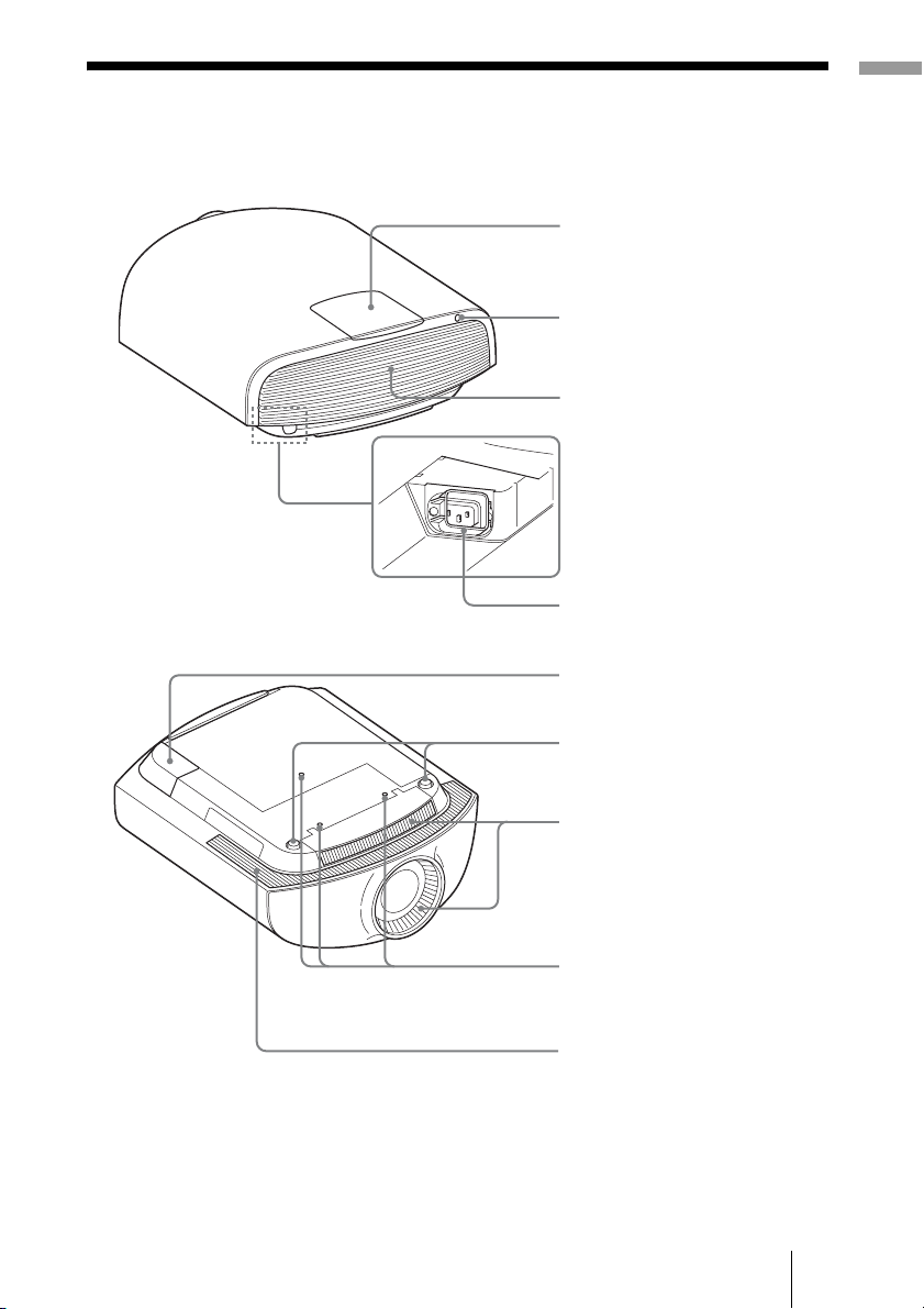
Rear/Bottom
Location of Controls
Lamp cover (1 page 73)
Remote control detector
(1 page 17)
Ventilation holes
(exhaust) (1 page 14)
AC IN socket (1 page 12)
AC inlet cover (supplied)
For details on how to attach the
AC inlet cover, see page 12.
Front feet (adjustable) (1 page 21)
Ventilation holes (intake)
(1 page 14)
Projector suspension
support attaching hole
(1 page 94)
Ventilation holes (intake)
(1 page 14)
9
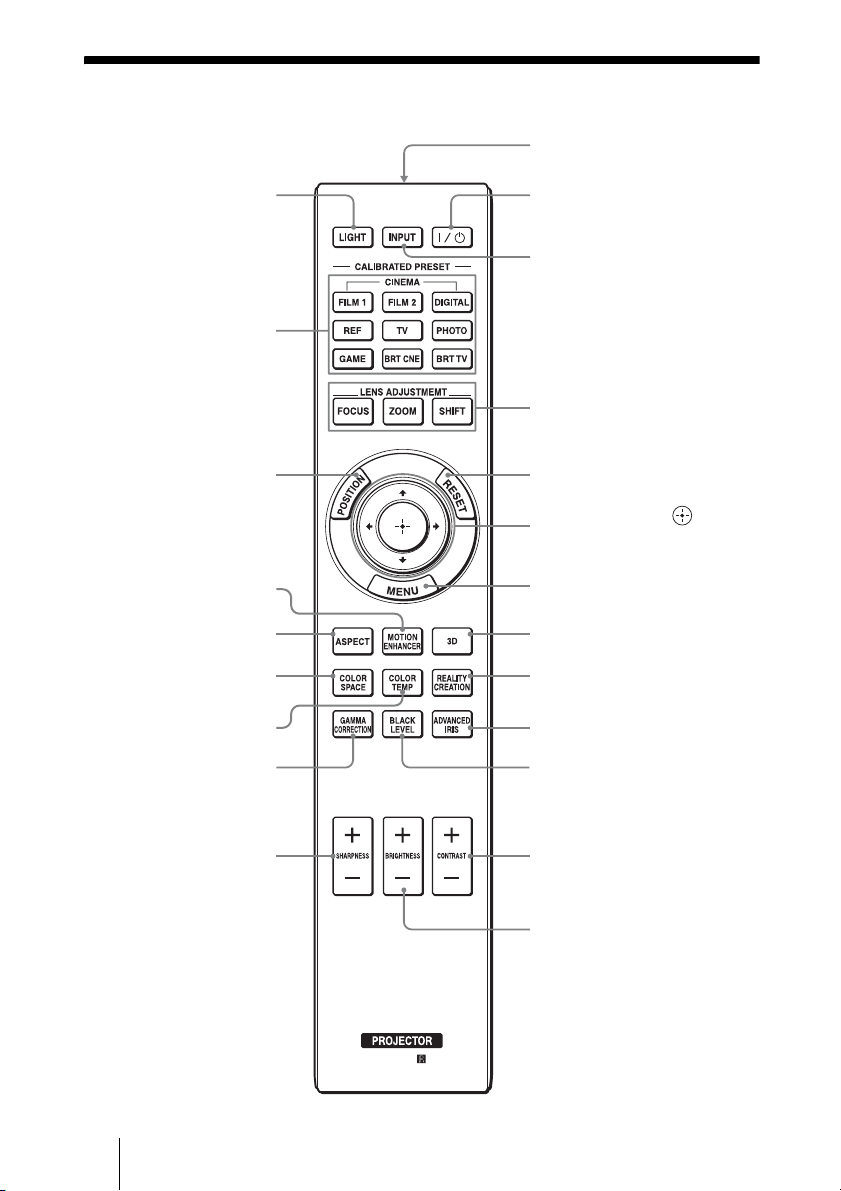
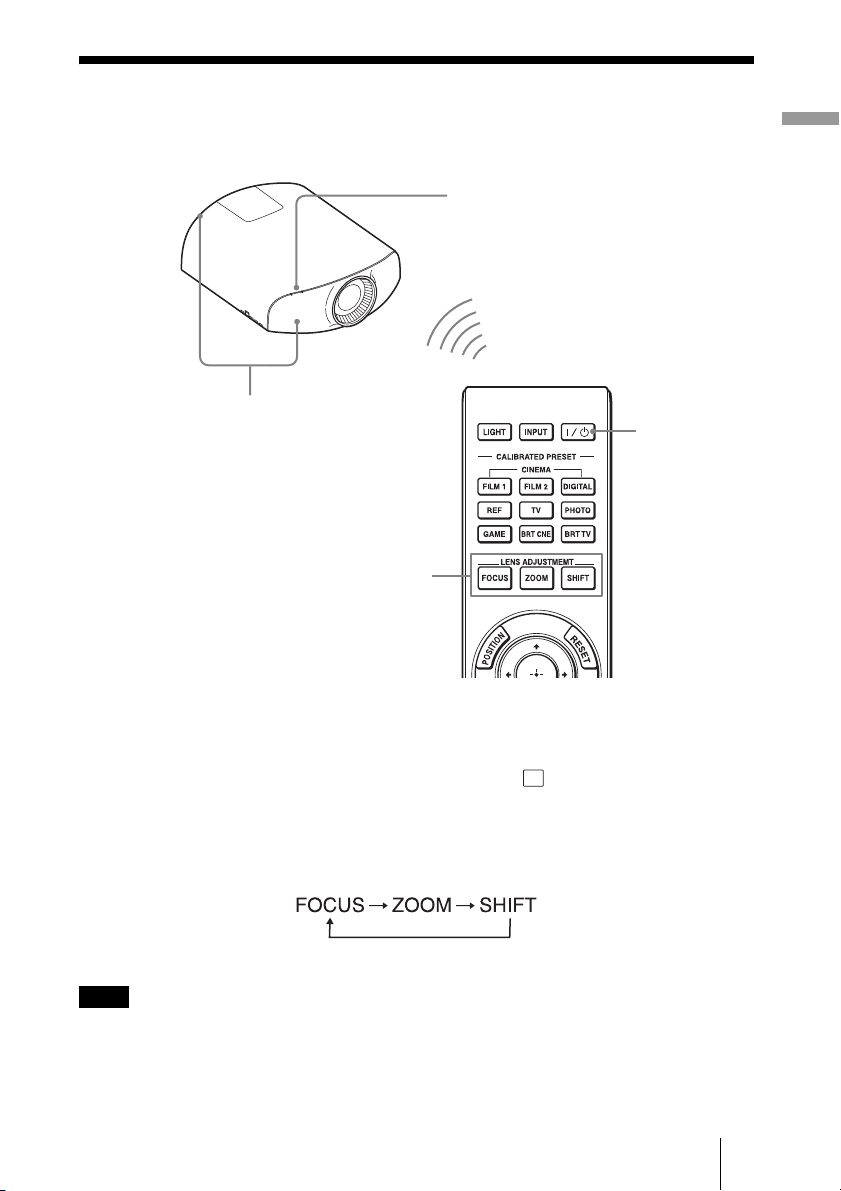
Remote Control
LIGHT button
Illuminates the buttons on
the remote control.
CALIBRATED PRESET
buttons (1 page 37)
Infrared transmitter
?/1 (ON/STANDBY)
button (1 page 18)
INPUT button (1 page 27)
LENS ADJUSTMENT buttons
(1 page 18)
POSITION button
(1 page 32)
MOTION ENHANCER
button (1 page 42)
ASPECT button
(1 page 34)
COLOR SPACE button
(1 page 46)
COLOR TEMP button
(1 page 43)
GAMMA CORRECTION
button (1 page 45)
SHARPNESS +/– button
(1 page 43)
RESET button (1 page 40)
M/m/</, (arrow)/ (enter)
buttons (1 page 39)
MENU button (1 page 39)
3D button (1 page 29)
REALITY CREATION button
(1 page 42)
ADVANCED IRIS button
(1 page 42)
BLACK LEVEL button
(1 page 44)
CONTRAST +/– button
(1 page 42)
BRIGHTNESS +/– button
(1 page 43)
10
Connections and Preparations
This section describes how to install the unit and screen, how to connect the equipment
from which you want to project the picture, etc.
Unpacking
Check the carton to make sure it contains the
following items:
• Remote control (1)
• Size AA (R6) manganese batteries (2)
• AC power cord for the projector (1)
•Plug holder (1)
• AC inlet cover (1)
•3D glasses (2)
• Pouch for the 3D glasses (2)
• USB charging AC power adaptor (1)
• AC power cord for USB charging AC
power adaptor (1)
• USB charging cable (G2551-0077-00/-01
or APY5244-010020/SONY) (1.2 m) (1)
• ImageDirector3 CD-ROM (1)
• Operating Instructions (this manual) (1)
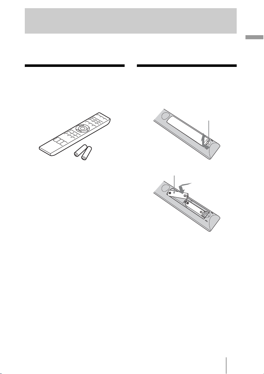
Inserting the Batteries into the Remote Control
Push and slide to
open.
Insert the batteries E
side first.
CAUTION
Danger of explosion if battery is incorrectly
replaced.
Replace only with the same or equivalent
type recommended by the manufacturer.
When you dispose of the battery, you must
obey the law in the relative area or country.
Connections and Preparations
ATTENTION
Il y a danger d’explosion s’il y a
remplacement incorrect de la batterie.
Remplacer uniquement avec une batterie du
même type ou d’un type équivalent
recommandé par le constructeur.
Lorsque vous mettez la batterie au rebut,
vous devez respecter la législation en
vigueur dans le pays ou la région où vous
vous trouvez.
11
VORSICHT
Explosionsgefahr bei Verwendung falscher
Batterien. Batterien nur durch den vom
Hersteller empfohlenen oder einen
gleichwertigen Typ ersetzen.
Wenn Sie die Batterie entsorgen, müssen Sie
die Gesetze der jeweiligen Region und des
jeweiligen Landes befolgen.
Installing batteries
Two size AA (R6) batteries are supplied for
Remote Control.
To avoid risk of explosion, use size AA (R6)
manganese or alkaline batteries.
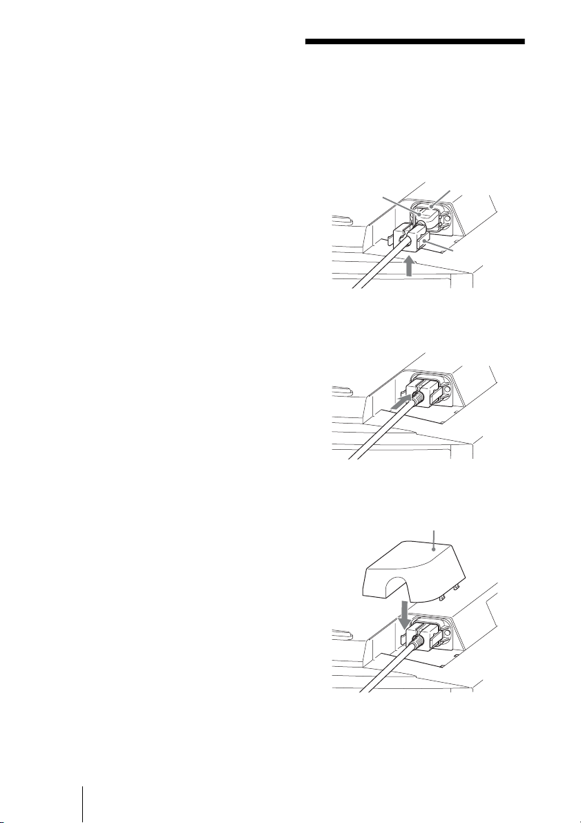
Connecting the AC Power Cord
1 Plug the AC power cord into the
AC IN socket, then attach the
plug holder to the AC power
cord.
AC power cord
(supplied)
AC IN socket
Caution about handling the remote
control
• Handle the remote control with care. Do
not drop or step on it, or spill liquid of any
kind onto it.
• Do not place the remote control in a
location near a heat source, a place subject
to direct sunlight, or a damp room.
Plug holder
(supplied)
2 Slide the plug holder over the
AC power cord to fix to the unit.
3 Attach the AC inlet cover to the
unit.
AC inlet cover (supplied)
12
Preparation 1: Installing the Unit
The lens shift allows you to have broader options for placing the unit and viewing pictures
easily.
Hot and humid
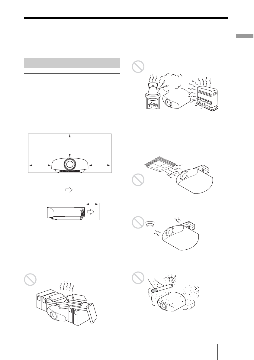
Before Setting Up the Unit
Unsuitable installation
Do not place the unit in the following
situations, which may cause malfunction or
damage to the unit.
Near walls
To maintain the performance and reliability
of the unit, leave space between walls and
the unit as illustrated.
30 cm
7
(11
/8inches)
30 cm
(11 7/8inches)
: Exhaust
30 cm
(11 7/8inches)
5 cm (2 inches)
Locations subject to direct cool or
warm air from an air-conditioner
Installing the unit in such a location may
cause a malfunction of the unit due to
moisture condensation or rise in
temperature.
Near a heat or smoke sensor
Malfunction of the sensor may occur.
Connections and Preparations
Leave a space of at least 5 cm (2 inches)
between the wall and the exhaust port side of
the unit. Note that the wall behind the unit
may become hot.
Poorly ventilated location
Leave space of more than 30 cm (11
7
/8
inches) around the unit.
Very dusty and extremely smoky
locations
13
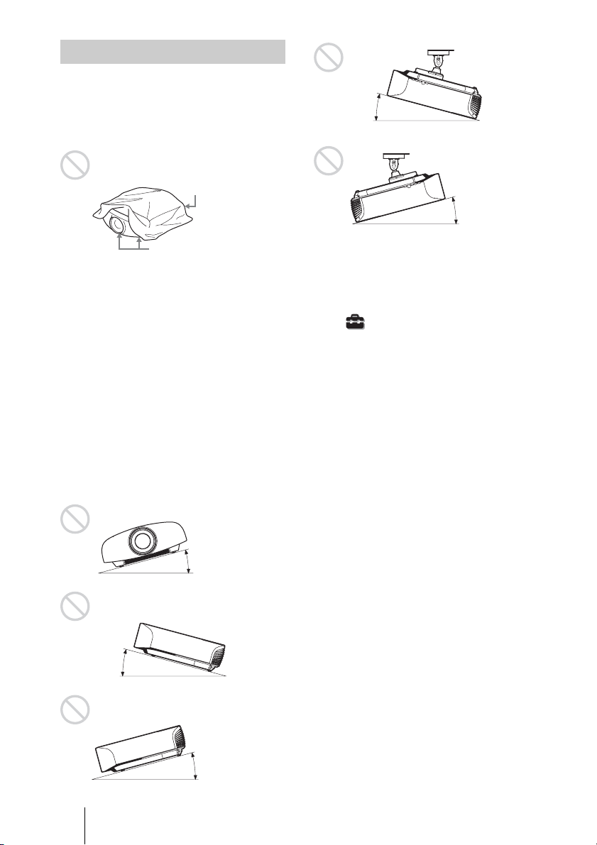
Notes on Use
Do not do any of the following while using
the unit.
Blocking the ventilation holes (intake
or exhaust)
Ventilation holes
(exhaust)
Ventilation holes
(intake)
For details on the location of the ventilation
holes (intake or exhaust), see “Location of
Controls” on page 8.
Tilting front/rear and left/right
Avoid using the unit tilted at an angle of
more than 15 degrees.
Do not install the unit anywhere other than
on a level surface or on the ceiling. Installing
the unit in such a location may result in
uneven color uniformity or reduce the
reliability of the effects of the lamp.
If the unit is tilted up or down, the image on
the screen may be trapezoidal.
Position the unit so that the lens is parallel to
the screen (1 page 16).
15° or more
15° or more
When installing the unit at high
altitudes
When using the unit at an altitude of
1,500 m or higher, set “Cooling Setting” on the
Setup menu to “High” (1 page 50).
Failing to set this mode when using the unit at
high altitudes could have adverse effects, such
as reducing the reliability of certain
components.
15° or more
14
15° or more
15° or more

WARNING
When installing the unit, incorporate a readily
accessible disconnect device in the fixed
wiring, or connect the power plug to an easily
accessible socket-outlet near the unit. If a fault
should occur during operation of the unit,
operate the disconnect device to switch the
power supply off, or disconnect the power
plug.
AVERTISSEMENT
Lors de l’installation de l’appareil, incorporer
un dispositif de coupure dans le câblage fixe ou
brancher la fiche d’alimentation dans une prise
murale facilement accessible proche de
l’appareil. En cas de problème lors du
fonctionnement de l’appareil, enclencher le
dispositif de coupure d’alimentation ou
débrancher la fiche d’alimentation.
WARNUNG
Beim Einbau des Geräts ist daher im Festkabel
ein leicht zugänglicher Unterbrecher
einzufügen, oder der Netzstecker muss mit
einer in der Nähe des Geräts befindlichen,
leicht zugängli chen Wandsteckdose verbunde n
werden. Wenn während des Betriebs eine
Funktionsstörung auftritt, ist der Unterbrecher
zu betätigen bzw. der Netzstecker abzuziehen,
damit die Stromversorgung zum Gerät
unterbrochen wird.
Connections and Preparations
15
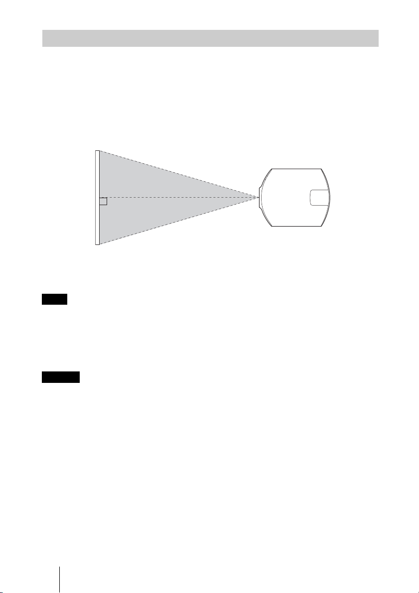
Installing the Unit
The installation distance between the unit and a screen varies depending on the size of the
screen or whether or not you use the lens shift features. Install this unit so that it fits the
size of your screen. For details on the distance between the unit and the screen (the
projection distance) and the size of projected video, see “Projection Distance and Lens
Shift Range” (1 page 89).
1 Position the unit so that the lens is parallel to the screen.
Top view
Screen
2 Project an image on the screen and adjust the picture so that it fits the
screen (1 page 17).
Note
When using a screen with an uneven surface, stripes pattern may rarely appear on the screen
depending on the distance between the screen and the unit or the zooming magnifications. This is
not a malfunction of the unit.
When installing the unit on the ceiling
Caution
Do not mount the projector on the ceiling or move it by yourself. Be sure to consult with
qualified Sony personnel (charged).
To dealers
Use the Sony PSS-H10 Projector Suspension Support, and take measures to prevent
falling using wire, etc.
For details, refer to the installation manual for dealers of the PSS-H10.
16
Preparation 2: Adjusting the Picture Position
Project an image on the screen and then adjust the picture position.
ON/STANDBY indicator
1
Remote control detector
3, 4, 5
LENS
ADJUSTMENT
buttons
2
?/1 (ON/
STANDBY)
button
Connections and Preparations
Tips
?/1 (ON/STANDBY), INPUT, MENU, and M/m/</,/ (joystick) buttons on the side
• The
panel of the unit function the same as those on the remote control. The LENS button functions in
the same way as the LENS ADJUSTMENT (FOCUS, ZOOM, SHIFT) buttons of the remote
control.
• When adjusting the lens, each time you press the LENS button on the unit, the lens adjustment
function switches between “Lens Focus,” “Lens Zoom” and “Lens Shift.”
Note
Depending on the installation location of the unit, you may not control it with the remote control. In
this case, point the remote control at the remote control detector of the unit or the screen.
17
1 After connecting the AC power
cord to the unit, plug the AC
power cord into a wall outlet.
The ON/STANDBY indicator lights in
red and the unit goes into standby mode.
Lights in red.
2 Press the ?/1 (ON/STANDBY)
button to turn on the unit.
Tip
When “Lens Control” is set to “Off” on the
Installation menu, you cannot adjust the
focus, the picture size or the proper position by
pressing the FOCUS, ZOOM or SHIFT buttons
(1 page 55).
When “Test Pattern” is set to “Off” on the
Function menu, the test pattern is not
displayed (1 page 54).
The lens protector will open.
The ON/STANDBY indicator flashes in
green, and then lights in green.
Flashes in green for
tens of seconds and
then lights in green.
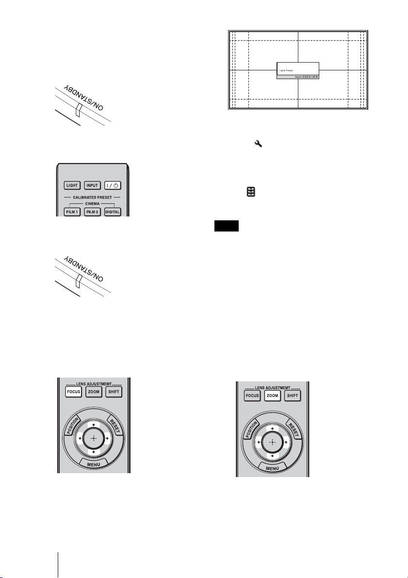
3 Adjust the focus.
Press the LENS ADJUSTMENT
(FOCUS) button to display the Lens
Focus adjustment window (test pattern).
Then adjust the focus of the picture by
pressing the M/m/</, buttons.
Note
Adjust the lens by using buttons on the remote
control or the control panel of the unit. Never
make adjustments by directly turning the lens
with your hands, which may cause damage or
malfunction to the unit.
4 Adjust the picture size.
Press the LENS ADJUSTMENT
(ZOOM) button to display the Lens
Zoom adjustment window (test pattern).
Then adjust the size of the picture by
pressing the M/m/</, buttons.
To make the picture larger, press M/,.
To make the picture smaller, press m/
<.
18
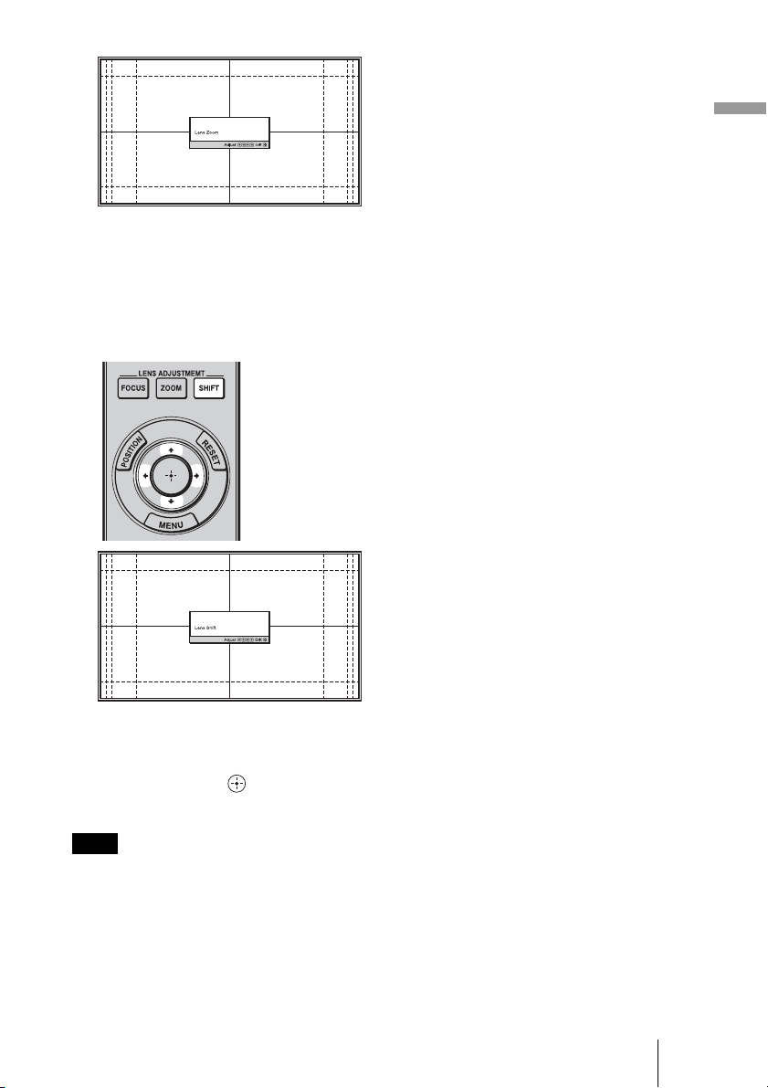
5 Adjust the picture position.
Press the LENS ADJUSTMENT
(SHIFT) button to display the Lens Shift
adjustment window (test pattern). Then
adjust to the proper position of the
picture by pressing the M/m/</,
buttons.
Connections and Preparations
Tip
The test pattern disappears when no operation
has been performed for one minute.
Whenever you press the button, the test
pattern disappears.
Note
When adjusting the window position, do not
touch the lens unit, otherwise your fingers may
be pinched by the moving parts.
19
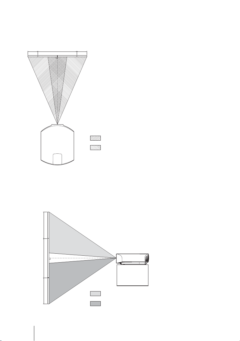
To adjust the horizontal position
Press </,.
The picture projected on the screen moves right or left by a maximum of 31% of the screen
width from the center of the lens.
31% 1 screen width 31%
Top view
: Picture position when moving the picture to the left
at maximum
: Picture position when moving the picture to the
right at maximum
To adjust the vertical position
Press M/m.
The picture projected on the screen moves up or down by a maximum of 80% of the screen
height from the center of the lens.
Side view
80%
1 screen
height
80%
20
: Picture position when moving the picture upward at
maximum
: Picture position when moving the picture downward at
maximum
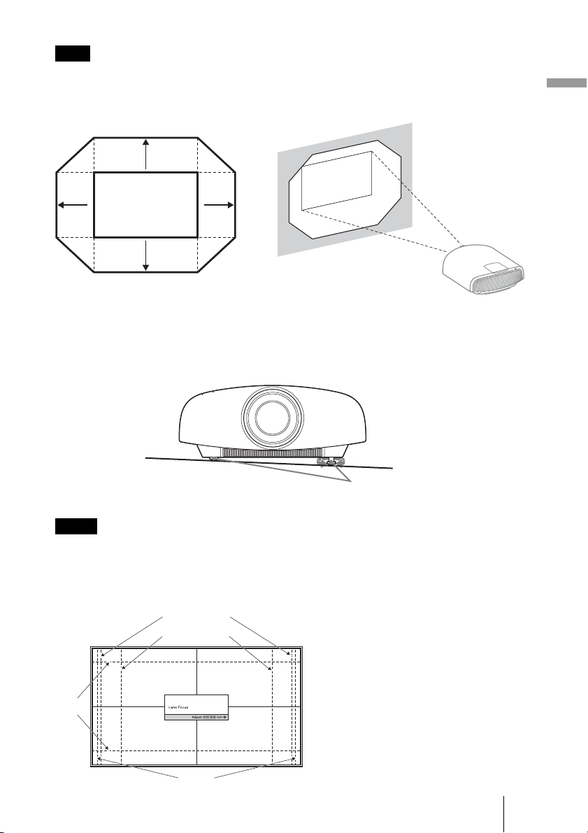
Note
The range to move the picture projected on the screen can be adjusted only within the octagon area
illustrated below. For details, see “Projection Distance and Lens Shift Range” (1 page 89).
Range of movement of
the projected picture
0.8V
Connections and Preparations
0.31H 0.31H
Projected Picture
0.8V
H: Width of the projected picture
V: Height of the projected picture
To adjust the tilt of the installation surface
If the unit is installed on an uneven surface, use the front feet (adjustable) to keep the unit
level.
Turn to adjust.
Front feet (adjustable)
Notes
• If the unit is tilted up or down, the projected image may be trapezoidal.
• Be careful not to catch your finger when turning the front feet (adjustable).
Lens adjustment window (test pattern)
2.35:1
1.78:1 (16:9)
1.33:1 (4:3)
1.85:1
The dashed lines show the screen sizes of
each aspect ratio.
21
Preparation 3: Connecting the Unit
When making connections, be sure to do the following:
• Turn off all equipment before making any connections.
• Use the proper cables for each connection.
• Insert the cable plugs properly; poor connection at the plugs may cause a malfunction or
poor picture quality. When pulling out a cable, be sure to pull it out from the plug, not
the cable itself.
• Refer to the operating instructions of the connected equipment.
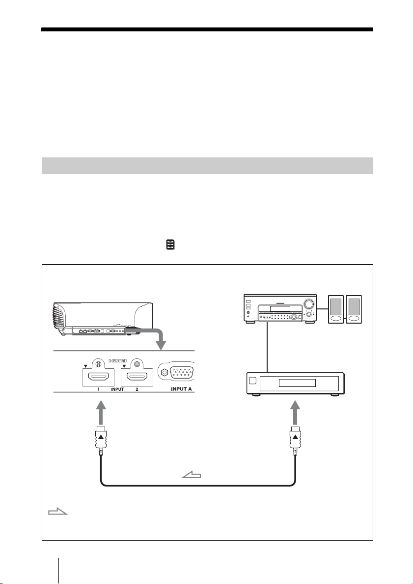
Connecting to a VCR
To connect to equipment with HDMI output connectors
You can enjoy better picture quality by connecting a DVD player/recorder, Blu-ray Disc
player/recorder, or PS3
Moreover, if you have a Control for HDMI compatible equipment, you can operate the
unit synchronizing with the Control for HDMI compatible equipment. For details, see
“HDMI Setting” of the Function menu (1 page 53) and “About the Control for
HDMI” (1 page 65).
®
equipped with HDMI output to the HDMI input of the unit.
Right side of the unit
: Video signal flow
22
AV amplifier
Equipment with HDMI output
connectors
HDMI cable (not supplied)
When using an optional HDMI cable, be sure to use a Sony
HDMI cable or other cable that has the HDMI logo.
Speakers
to HDMI output
Notes
• Use a high-speed HDMI cable. With a standard HDMI cable, images of 1080p, DeepColor, 3D
video and 4K video may not be displayed properly.
• When connecting an HDMI cable to the unit, make sure the
input of the unit and the
v mark on the connector of the cable is set at the same position.
V mark on the upper part of the HDMI
• If the picture from equipment connected to the unit with an HDMI cable is not correct, check the
settings of the connected equipment.
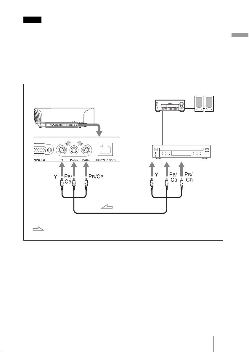
To connect to equipment with component video output
connectors
Connections and Preparations
Right side of the unit
: Video signal flow
Component video cable (not supplied)
AV amplifier
Equipment with component
video output connectors
Speakers
23
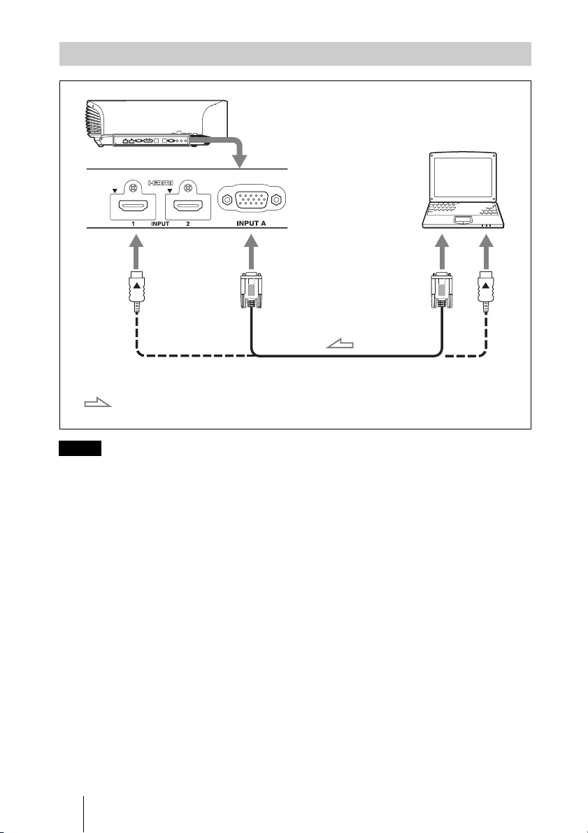
Connecting to a Computer
Right side of the unit
HD-Dsub15 pin cable (not supplied) or HDMI cable (not supplied)
Computer
to monitor output
: Video signal flow
Notes
When using an optional HDMI cable, be sure to use a Sony
HDMI cable or other cable that has the HDMI logo.
• Use a high-speed HDMI cable. With a standard HDMI cable, images of 1080p video may not be
displayed properly.
• When connecting an HDMI cable, make sure the
V mark on the upper part of the HDMI input of
the unit and the v mark on the connector of the cable is set at the same position.
• If you set your computer, such as a notebook type, to output the signal to both computer’s display
and this equipment, the picture of the equipment may not appear properly. Set your computer to
output the signal to only the external monitor.
For details, refer to the computer’s operating instructions supplied with your computer. For
settings of the computer, consult with the manufacturer of the computer.
• If the picture from equipment connected to the unit with an HDMI cable is not correct, check the
settings of the connected equipment.
24
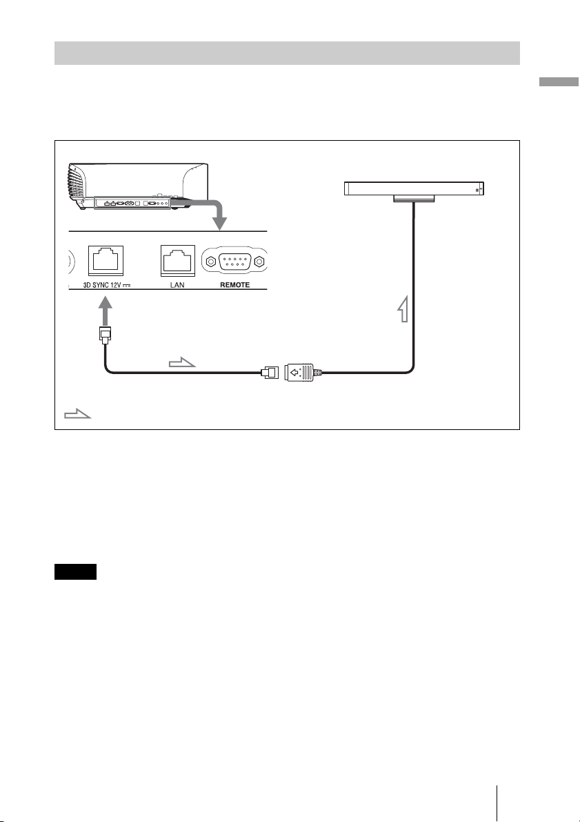
Connecting to a 3D Sync Transmitter
This unit incorporates a 3D Sync Transmitter. Depending on the installation environment
of the unit, the 3D glasses may not receive 3D signals properly from the unit’s built-in 3D
Sync Transmitter. In this case, connect an optional 3D Sync Transmitter and place it near
your viewing position.
Right side of the unit
3D Sync Transmitter (not supplied)
LAN cable (not supplied)
: 3D sync signal flow
Tip
Place the optional 3D Sync Transmitter directly facing the 3D glasses. Also, in order to stabilize
operation of the 3D glasses, it is recommended that you place the 3D Sync Transmitter near your
viewing position.
Connections and Preparations
CAUTION
Be sure to use straight-type LAN cable of up to 15 m labeled TYPE CM, and do not use
an extension cord.
Notes
• The 3D SYNC connector is dedicated for the optional 3D Sync Transmitter. Do not connect
computers or other network devices, to avoid malfunction.
• You can use a 3D Sync Transmitter separate from this unit, using an optional LAN cable (straighttype).
If the usage environment has interference of a continuous specific frequency, synchronization of
3D image signals and the 3D glasses may be lost. In this case, use a LAN cable labeled Category 7.
When watching 3D images in an environment that has even more interference, use the internal
transmitter.
• Be sure to use cable of up to 15 m, and do not use an extension cord. Also, keep the LAN cable
away from any AC power cords as much as possible.
• Only one 3D Sync Transmitter should be connected to the unit. Connecting multiple 3D Sync
Transmitters may cause a malfunction.
• When connected to the 3D Sync Transmitter, the built-in 3D Sync Transmitter feature of the unit
will turn off. You cannot use both at the same time.
25
Preparation 4: Selecting the Menu Language
You can select one of 16 languages for
displaying the menu and other on-screen
displays. The factory default setting is
English. To change the current menu
language, set the desired language with the
menu screen.
2,3,4
M/m/</,
(arrow)/ (enter)
buttons
The setting items of the selected menu
appear.
1
MENU button
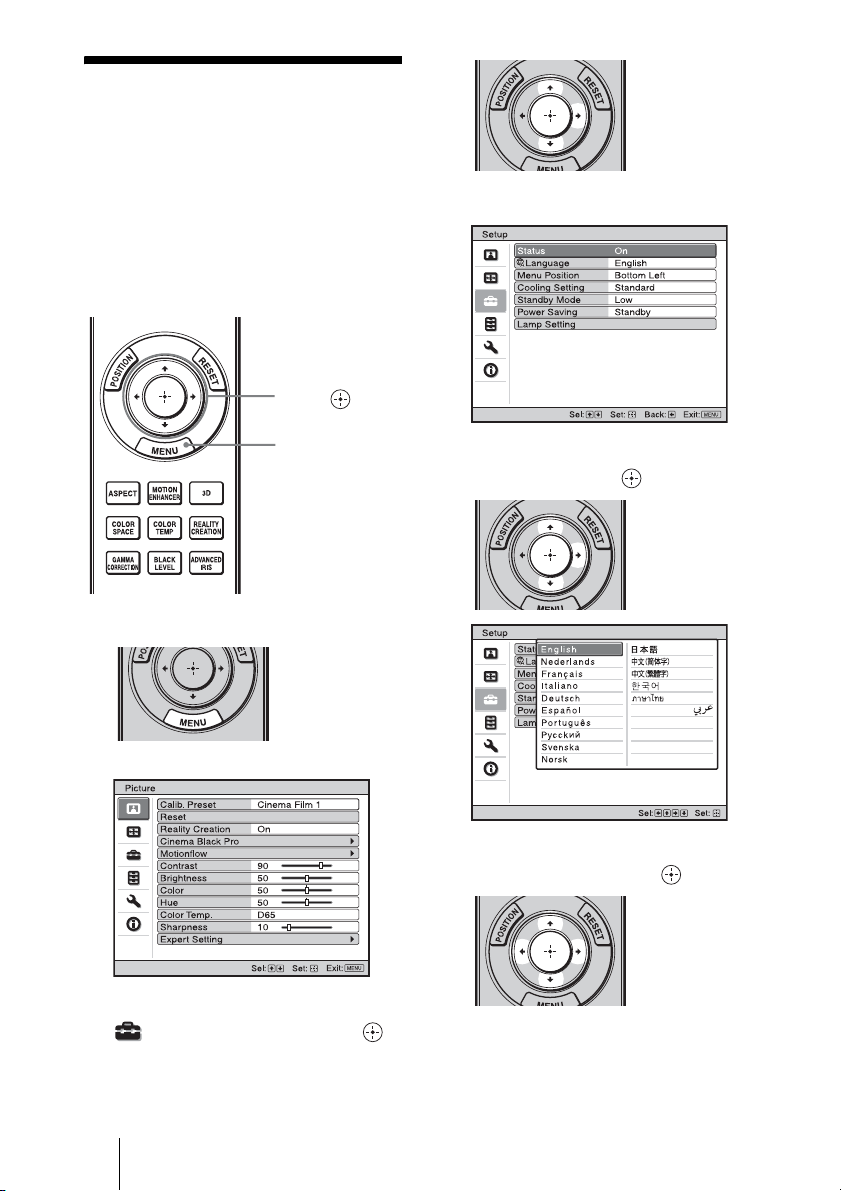
1 Press MENU.
The menu appears.
2 Press M/m to select the Setup
menu, and press , or .
3 Press M/m to select “Language,”
and press , or .
4 Press M/m/</, to select a
language, and press .
The menu changes to the selected
language.
26
To clear the menu
Press MENU.
Projecting
This section describes how to operate the unit to view the picture from the equipment
connected to the unit. It also describes how to adjust the quality of the picture to suit your
taste.
Projecting
Projecting the Picture
1 Power on both the unit and the
equipment connected to the
unit.
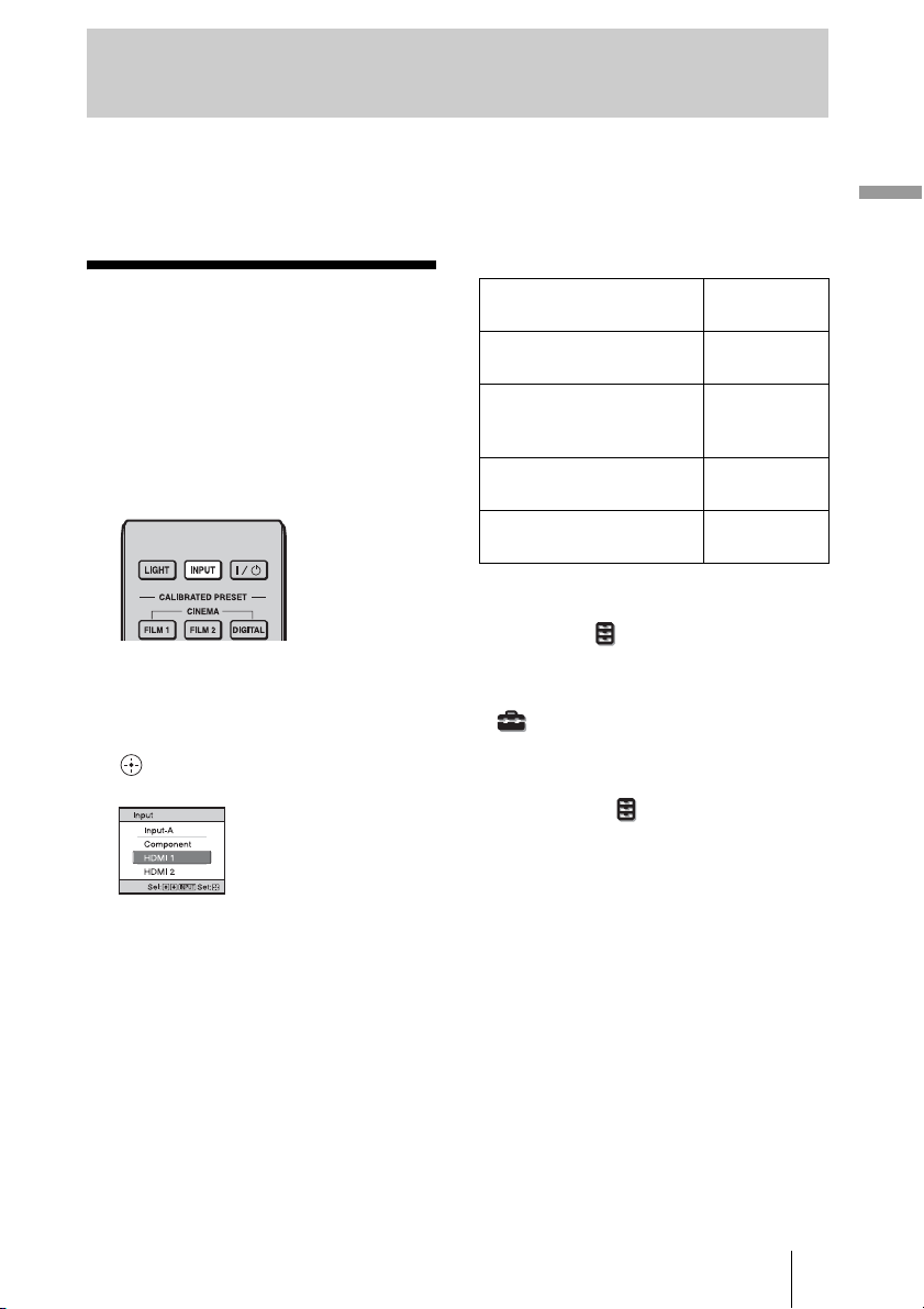
2 Press INPUT to display the input
palette on the screen.
3 Select the equipment from
which you want to display
images.
Press INPUT repeatedly or press M/m/
(enter) to select the equipment from
which to project.
Example: To view the picture from
the video equipment
connected to the HDMI 1
connector of this unit.
To view the picture from Press INPUT
RGB equipment connected
to the INPUT A connector
Component equipment
connected to the Y P
R/CR connector
P
Equipment connected to the
HDMI 1 connector
Equipment connected to the
HDMI 2 connector
Tips
• When “Auto Input Search” is set to “On” on
the Function menu, only input terminals
with effective signals are displayed in the
input palette.
• When “Status” is set to “Off” on the Setup
menu, the input palette does not appear.
Press the INPUT button to switch between
input terminals in sequence.
• When the “Control for HDMI” is set to “On”
on the Function menu, the input terminal
with effective signals is automatically
displayed, synchronizing with the operation
of the equipment connected to HDMI 1 or
HDMI 2 input of the unit. (Only when the
connected equipment supports Control for
HDMI compatible.)
B/CB
to display
Input-A
Component
HDMI 1
HDMI 2
27

Turning Off the Power
1 Press the ?/1 (ON/STANDBY)
button.
A message “POWER OFF?” appears on
the screen.
2 Press the ?/1 (ON/STANDBY)
button again before the
message disappears.
The lens protector will close. Be careful
not to catch your fingers or any objects.
The ON/STANDBY indicator flashes in
green and the fan continues to run to
reduce the internal heat. First, the ON/
STANDBY indicator flashes quickly,
during which you will not be able to
light up the ON/STANDBY indicator
with the ?/1 (ON/STANDBY) button.
The fan stops and the ON/STANDBY
indicator changes from flashing green to
remaining red.
The power is turned off completely, and
you can disconnect the AC power cord.
Note
Never disconnect the AC power cord while
the indicator is flashing.
You can turn off the unit by holding the ?/1
(ON/STANDBY) button for about 1 second,
instead of performing the above steps.
Watching 3D Video Images
You can enjoy powerful 3D video images,
such as from 3D games and 3D Blu-ray
Discs, using the supplied 3D glasses.
1 Turn on the HDMI equipment for
3D compatibility connected to
the unit, then play the 3D
content.
For details on how to play 3D content,
refer to the operating instructions for the
connected equipment.
2 Turn on the unit and project the
3D video image onto the screen.
For details on how to project the image,
see “Projecting the Picture” (1 page
27).
3 Turn on the 3D glasses, and
then put them on so that they fit
comfortably.
For details on how to use the 3D glasses,
see “Using the 3D Glasses” (1 page
29).
Tips
• The factory default setting for ”2D-3D
Display Sel.” is “Auto” to allow projecting
3D video images automatically when the unit
detects 3D signals.
• To convert 3D video images to 2D video
images, set “2D-3D Display Sel.” to “2D”
(1 page 52).
28
Notes
• It may not be possible to display 3D video
image, depending on the type of signal. Set
the “2D-3D Display Sel.” to “3D,” and “3D
Format” to “Side-by-Side” or “Over-Under”
to suit the format of the 3D content you want
to watch (1 page 52).
• Use the 3D glasses within the
communication range (1 page 30).
• You can watch 3D video images only when
signals from HDMI input. When connecting
3D equipment such as a 3D game or 3D Bluray Disc player to the unit, use an HDMI
cable.
• There are differences in perception of 3D
video images among individuals.
• When the temperature of the usage
environment is low, the 3D effect may be
diminished.
Adjusting/Setting the 3D
functions
You can adjust/set the 3D functions by
pressing the 3D button on the remote control
or with the “3D Settings” of the Function
menu. For details, see “3D Settings” (1
page 52).
Using the 3D Glasses
The 3D glasses receive signals from the 3D
Sync Transmitter built into the front of the
unit, which are reflected to the glasses from
the screen. When watching 3D video images
using the 3D glasses, face squarely toward
the screen.
Precautions for use
The 3D glasses receive infrared signals sent
by the 3D Sync Transmitter built into the
front of the unit, which are reflected to the
glasses from the screen.
Misoperation may occur if:
– The 3D glasses do not face the screen
– There are objects blocking the path
between the 3D glasses and the screen
– The viewing position is too far from the
screen or the distance between the unit and
screen is too great
– There are other infrared communication
devices nearby
Projecting
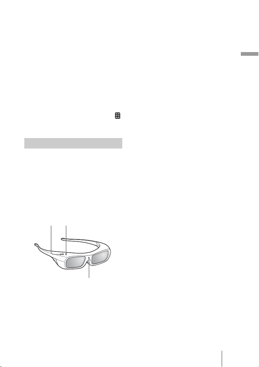
1 Press the power button on the
3D glasses.
The LED indicator lights up in green.
LED indicatorPower button
IR sensor
2 Put on the 3D glasses.
3 Turn toward the screen.
29
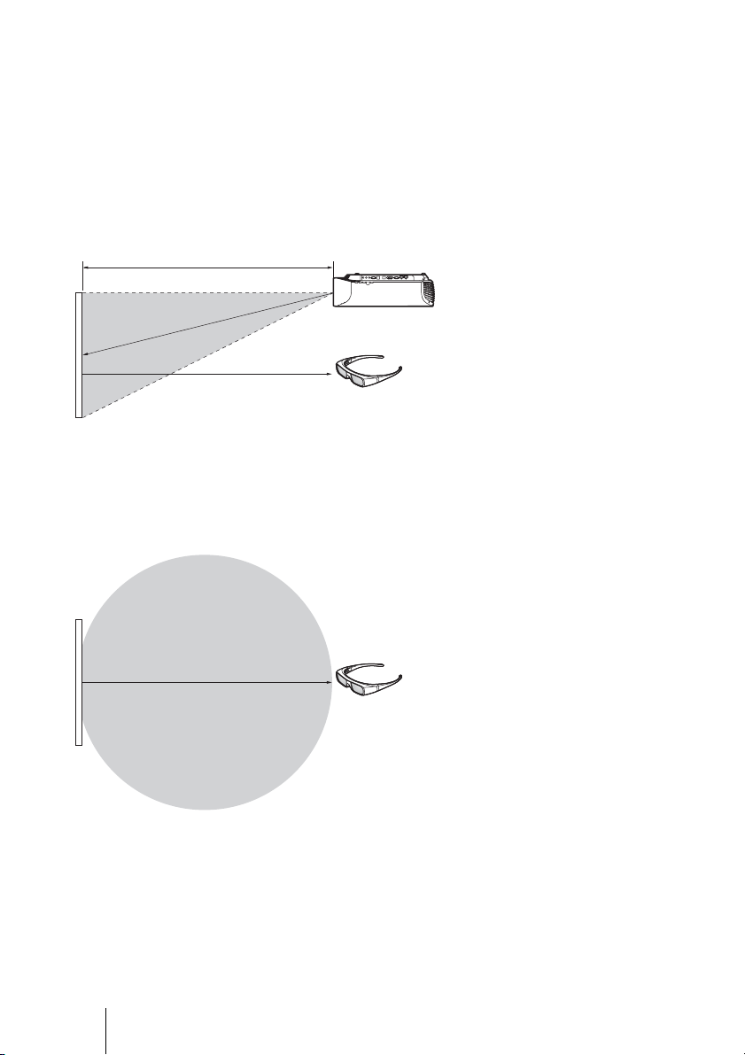
3D glasses communication range
Figures A and B below indicate the communication range of the 3D glasses. If you try to
watch 3D video images from a distance greater than the communication range or install
the unit outside the communication range, the 3D glasses may not be able to display the
images properly. Also, the viable angles and distance vary depending on the screen type,
environment of the room, and installation environment of the unit.
Figure A: 3D sync signal communication distance (Shift Range: 0.5 V)
Side view
a
Projector
b
a + b = 13 m (Maximum)
Screen
3D glasses
Figure B: 3D glasses communication range (The figure shows the distance
between the screen and the projector as 8 m.)
Top or side view
Approx. 5 m (Maximum)
Screen
3D glasses
30
 Loading...