

Sony VPLVW-100 Service manual

VIDEO PROJECTOR
VPL-VW100
REMOTE COMMANDER
RM-PJVW100
SERVICE MANUAL
1st Edition (Revised 1)
! WARNING
This manual is intended for qualified service personnel only.
To reduce the risk of electric shock, fire or injury, do not perform any servicing other than that
contained in the operating instructions unless you are qualified to do so. Refer all servicing to
qualified service personnel.
! WARNUNG
Die Anleitung ist nur für qualifiziertes Fachpersonal bestimmt.
Alle Wartungsarbeiten dürfen nur von qualifiziertem Fachpersonal ausgeführt werden. Um die
Gefahr eines elektrischen Schlages, Feuergefahr und Verletzungen zu vermeiden, sind bei
Wartungsarbeiten strikt die Angaben in der Anleitung zu befolgen. Andere als die angegeben
Wartungsarbeiten dürfen nur von Personen ausgeführt werden, die eine spezielle Befähigung
dazu besitzen.
! AVERTISSEMENT
Ce manual est destiné uniquement aux personnes compétentes en charge de l’entretien. Afin
de réduire les risques de décharge électrique, d’incendie ou de blessure n’effectuer que les
réparations indiquées dans le mode d’emploi à moins d’être qualifié pour en effectuer d’autres.
Pour toute réparation faire appel à une personne compétente uniquement.
CAUTION
RISK OF EXPLOSION IF BATTERY IS REPLACED BY INCORRECT TYPE.
DISPOSE OF USED BATTERIES ACCORDING TO THE RULE IN REGION.
VPL-VW100

Table of Contents
1. Service Information
1-1. Appearance Figure ..........................................................1-1
1-2. Board Locations ..............................................................1-1
1-3. Disassembly ....................................................................1-2
1-3-1. Top Cover Assembly ............................................. 1-5
1-3-2. Lamp Cover ...........................................................1-6
1-3-3. Lamp ...................................................................... 1-6
1-3-4. L Board ..................................................................1-7
1-3-5. Louver (F) Assembly ............................................ 1-7
1-3-6 Front Cover Assembly and HB Board ..................1-8
1-3-7. Hood Section .........................................................1-9
1-3-8. UA Board and UB Board ...................................... 1-9
1-3-9. HA Block Assembly ............................................ 1-10
1-3-10. Hood Assembly and NR Board ...........................1-11
1-3-11. GB Board ............................................................. 1-12
1-3-12. Lamp Power Supply ............................................ 1-12
1-3-13. Optics Unit Assembly-1 ...................................... 1-13
1-3-14. Optics Unit Assembly-2 ...................................... 1-14
1-3-15. Igniter .................................................................. 1-15
1-3-16. TA Board .............................................................1-15
1-3-17. D.C. Motor SFF21C/C-NP (Right)
and D.C. Motor SFF21C/C-NP (Left) ................. 1-16
1-3-18. GA Board ............................................................1-17
1-3-19. D.C. Fan (Sirocco) .............................................. 1-17
1-3-20. Q Board ............................................................... 1-18
1-3-21. F Board ................................................................1-19
1-3-22. Bottom Cover Assembly ..................................... 1-19
1-3-23. Extension Boards and Extension Cables .............1-20
1-3-24. Extension Boards Connection ............................. 1-20
1-4. Network ........................................................................1-22
1-4-1. Overview ............................................................. 1-22
1-4-2. Service Preparation ............................................. 1-22
1-4-3. Firmware Update Function .................................. 1-24
1-4-4. Event Trace Function .......................................... 1-31
1-4-5. Network Reset ..................................................... 1-34
1-5. Unleaded Solder ............................................................ 1-34
1-6. Service Know-How ...................................................... 1-35
1-6-1. When the Optical Unit ASSY is Replaced ..........1-35
1-6-2. When the Board is Replaced ............................... 1-35
1-6-3. IRIS Adjustment .................................................. 1-35
1-7. Upgrading the Software ................................................1-35
1-8. Memory ......................................................................... 1-37
2. Electrical Adjustments
2-1. Preparations .................................................................... 2-1
2-1-1. Required Equipment .............................................. 2-1
2-1-2. Factory Mode Setting ............................................2-1
2-2. Adjustment Item Initialize Data ...................................... 2-2
2-3. White Balance Adjustment on Servicing ........................2-9
2-3-1. Component ............................................................ 2-9
2-3-2. Computer .............................................................2-10
3. Semiconductors
4. Spare Parts
4-1. Notes on Repair Parts ..................................................... 4-1
4-2. Exploded Views .............................................................. 4-2
4-3. Electrical Parts List ....................................................... 4-14
5. Block Diagrams
C (1/2) ........................................................................................ 5-1
C (2/2) ........................................................................................ 5-2
GA, GB (1/2), F ......................................................................... 5-3
GB (2/2) ..................................................................................... 5-4
C, F, GA, HA, HB, L, NF, NR, Q, QB, TA, TL, V ..................5-5
Q (1/6) ....................................................................................... 5-6
Q (2/6) ....................................................................................... 5-7
Q (3/6) ....................................................................................... 5-8
Q (4/6) ....................................................................................... 5-9
Q (5/6) ..................................................................................... 5-10
Q (6/6) ..................................................................................... 5-11
VPL-VW100
1

6. Diagrams
6-1. Frame Schematic Diagrams ............................................6-2
6-2. Schematic Diagrams and Printed Wiring Boards ........... 6-3
Schematic Diagrams
Q (1/24) ...........................................................................6-3
Q (2/24) ...........................................................................6-4
Q (3/24) ...........................................................................6-5
Q (4/24) ...........................................................................6-6
Q (5/24) ...........................................................................6-7
Q (6/24) ...........................................................................6-8
Q (7/24) ...........................................................................6-9
Q (8/24) ......................................................................... 6-10
Q (9/24) ......................................................................... 6-11
Q (10/24) ....................................................................... 6-12
Q (11/24) ....................................................................... 6-13
Q (12/24) ....................................................................... 6-14
Q (13/24) ....................................................................... 6-15
Q (14/24) ....................................................................... 6-16
Q (15/24) ....................................................................... 6-17
Q (16/24) ....................................................................... 6-18
Q (17/24) ....................................................................... 6-19
Q (18/24) ....................................................................... 6-20
Q (19/24) ....................................................................... 6-21
Q (20/24) ....................................................................... 6-22
Q (21/24) ....................................................................... 6-23
Q (22/24) ....................................................................... 6-24
Q (23/24) ....................................................................... 6-25
Q (24/24) ....................................................................... 6-26
C (1/9) ...........................................................................6-32
C (2/9) ...........................................................................6-33
C (3/9) ...........................................................................6-34
C (4/9) ...........................................................................6-35
C (5/9) ...........................................................................6-36
C (6/9) ...........................................................................6-37
C (7/9) ...........................................................................6-38
C (8/9) ...........................................................................6-39
C (9/9) ...........................................................................6-40
F .................................................................................... 6-43
GA (1/2) ........................................................................6-46
GA (2/2) ........................................................................6-47
GB (1/5) ........................................................................ 6-50
GB (2/5) ........................................................................ 6-51
GB (3/5) ........................................................................ 6-52
GB (4/5) ........................................................................ 6-53
GB (5/5) ........................................................................ 6-54
HA ................................................................................. 6-56
HB .................................................................................6-57
L ....................................................................................6-58
NF ................................................................................. 6-58
NR .................................................................................6-58
TA ................................................................................. 6-59
TL ................................................................................. 6-59
UA ................................................................................. 6-60
UB .................................................................................6-60
V ................................................................................... 6-60
Printed Wiring Boards
Q ................................................................................... 6-28
C ....................................................................................6-30
F .................................................................................... 6-42
GA ................................................................................. 6-44
GB .................................................................................6-48
HA ................................................................................. 6-56
HB .................................................................................6-57
L ....................................................................................6-58
NF ................................................................................. 6-58
NR .................................................................................6-58
TA ................................................................................. 6-59
TL ................................................................................. 6-59
UA ................................................................................. 6-60
UB .................................................................................6-60
V ................................................................................... 6-60
2
VPL-VW100
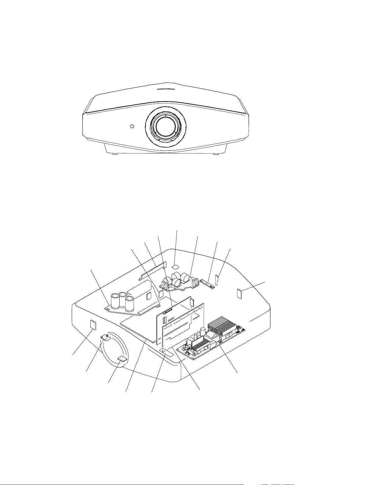
1-1. Appearance Figure
Section 1
Service Information
1-2. Board Locations
GA
NF
TA
UA
HA
C
UB
F
L
TL
NR
Lamp power supply
VPL-VW100
V
Q
HB
GB
1-1
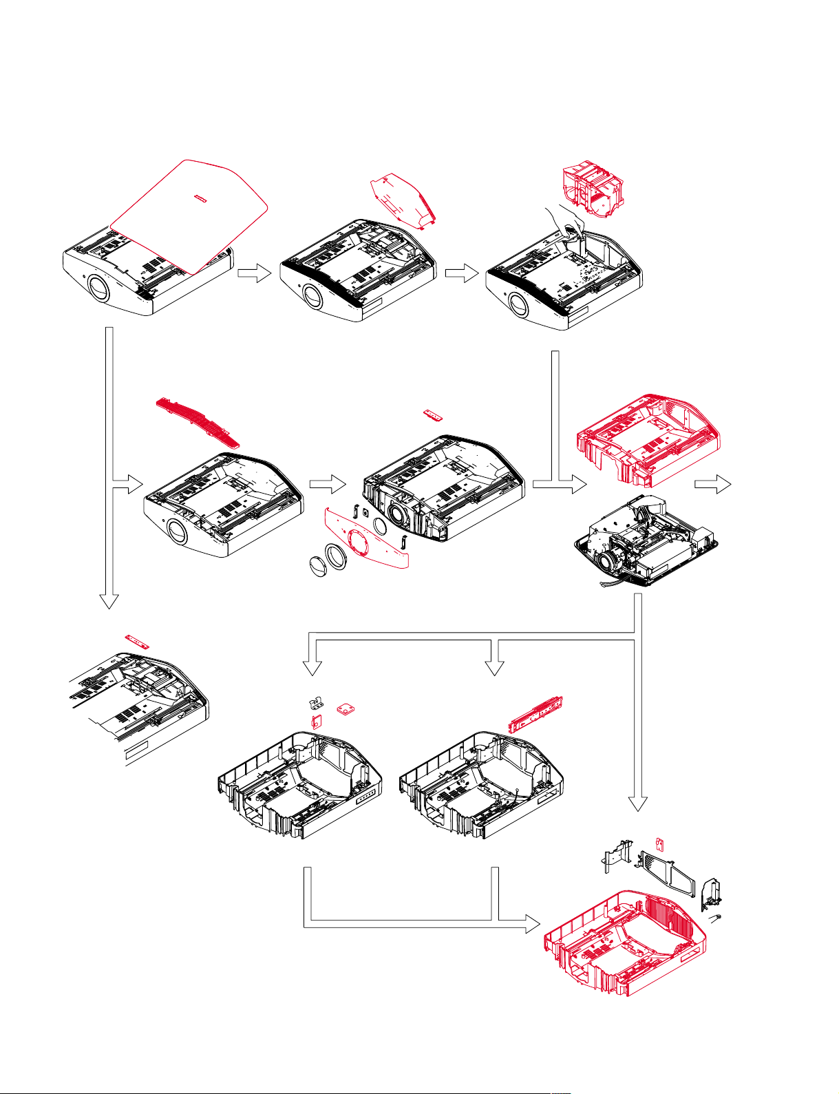
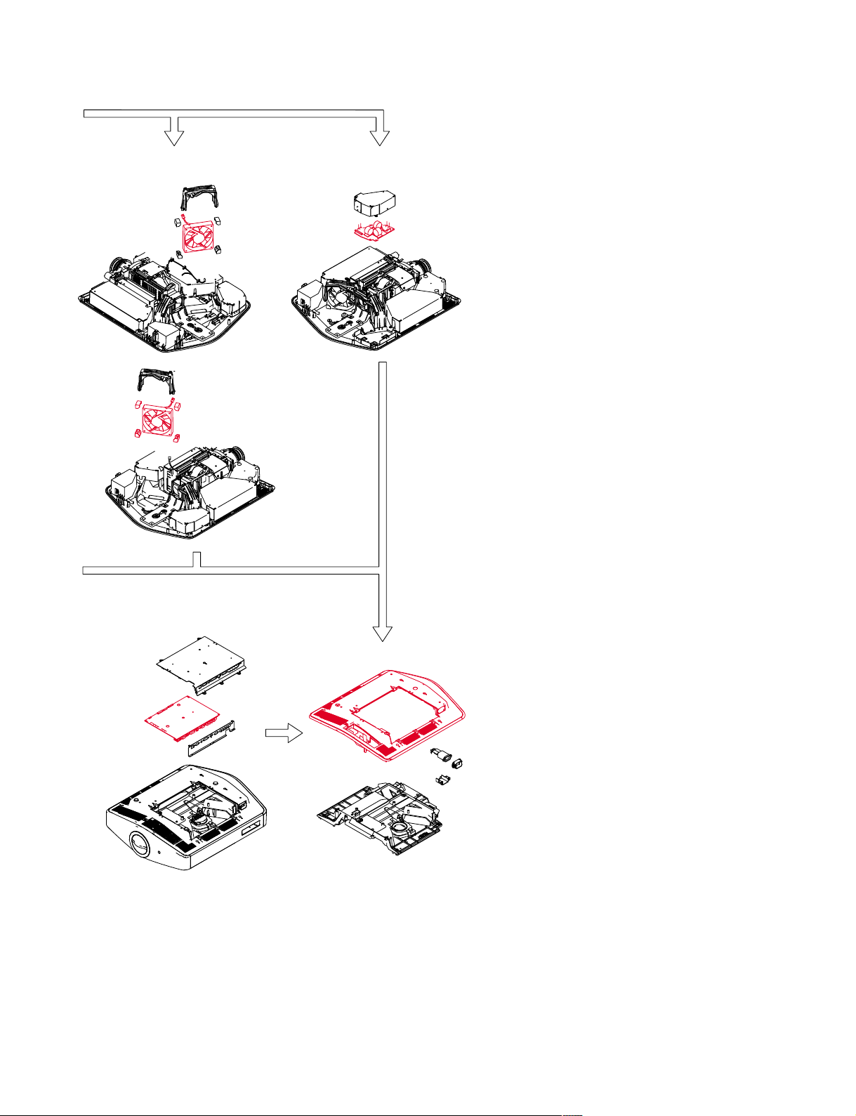
1-3. Disassembly
1-3-1. Top Cover Assembly
1-3-5. Louver (F) Assembly 1-3-6. Front Cover Assembly
1-3-2. Lamp Cover 1-3-3. Lamp
and HB Board
1-3-7. Hood Section
A
1-3-4. L Board
1-3-9. HA Block Assembly1-3-8. UA Board and UB Board
1-3-10. Hood Assembly and NR Board
1-2
VPL-VW100
A
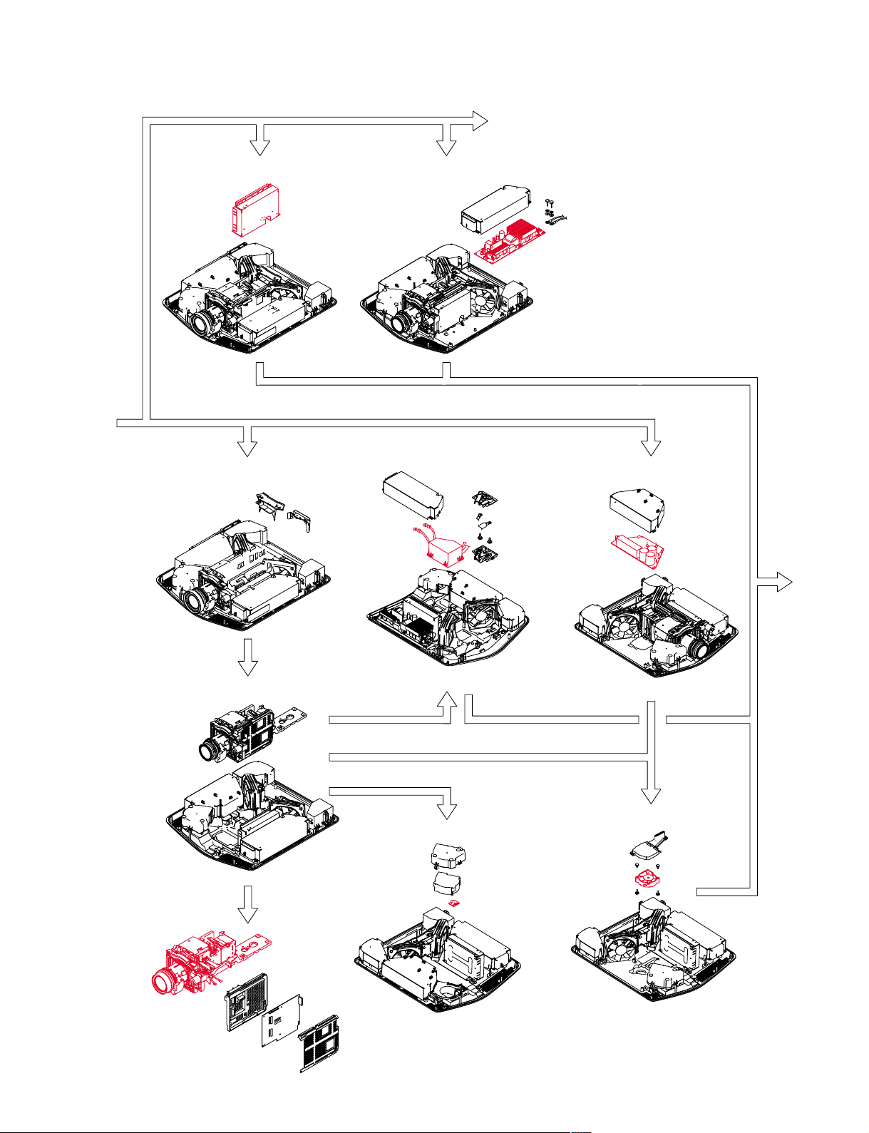
1-3-11. GB Board
A
1-3-13. Optics Unit Assembly-1
1-3-12. Lamp Power Supply
1-3-15. Igniter
1-3-18. GA Board
1-3-14. Optics Unit Assembly-2
B
1-3-19. D.C. Fan (Sirocco)
1-3-16. TA Board
VPL-VW100
1-3
A
1-3-17. 0. Motor SFF21C/C-NP (Right) and
D.C. Motor SFF21C/C-NP (Left)
1-3-21. F Board
B
1-3-20. Q Board
1-3-22. Bottom Cover Assembly
1-4
VPL-VW100
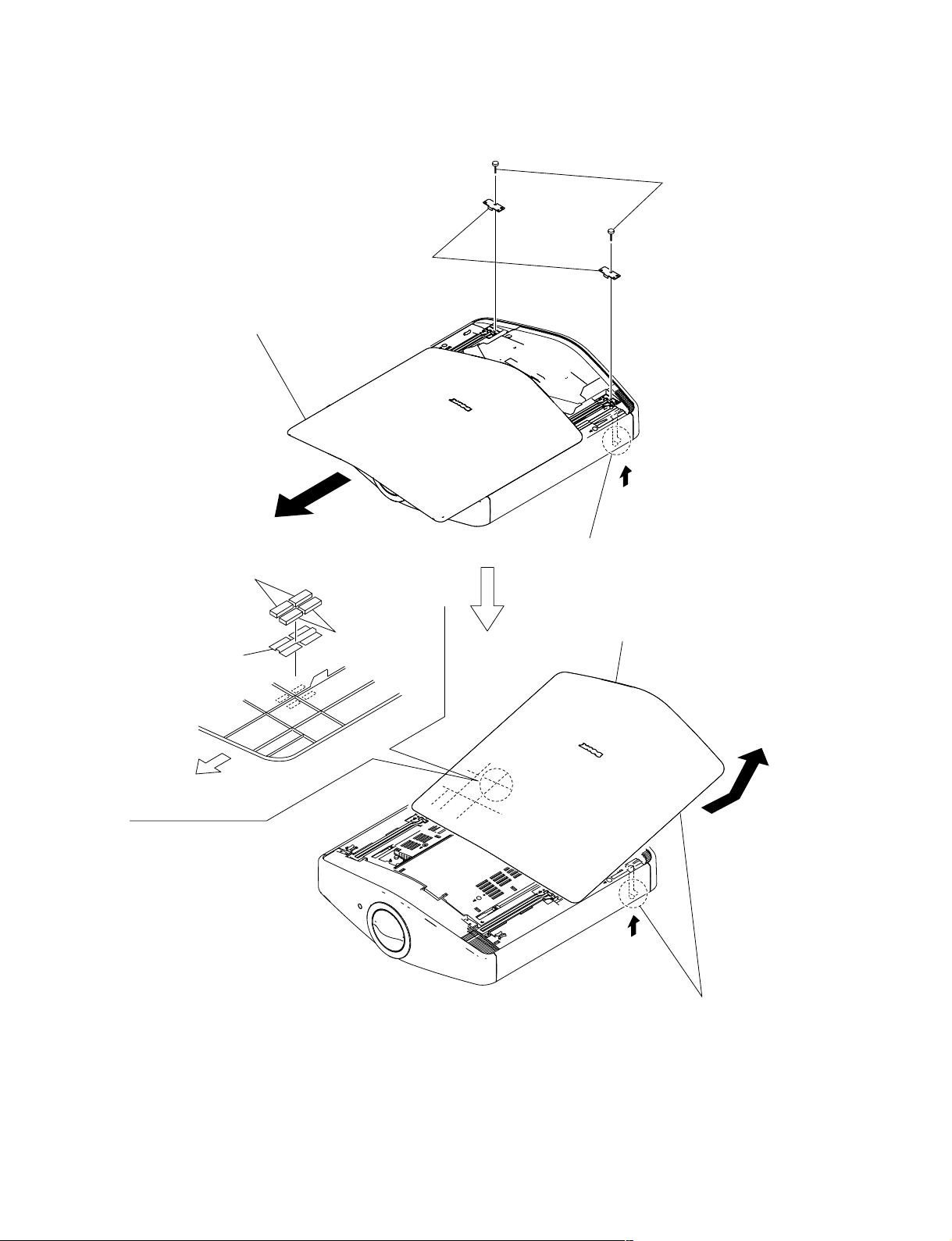
1-3-1. Top Cover Assembly
3
Two screws
(+PSW M3 x 8)
2
Open the top cover assembly
in the direction of the arrow
B
6
Gasket (T)
8
EMC plate (T)
4 Two r
B
.
7
Gasket (T2)
ail ends
A
1
Push the pusher in the direction of arrow A.
9
Top cover assembly
Front Cover Side
of Unit
C
A
5
While pushing the pusher in the direction
of arrow
in the direction of arrow
A
, remove the top cover assembly
C
.
VPL-VW100
1-5
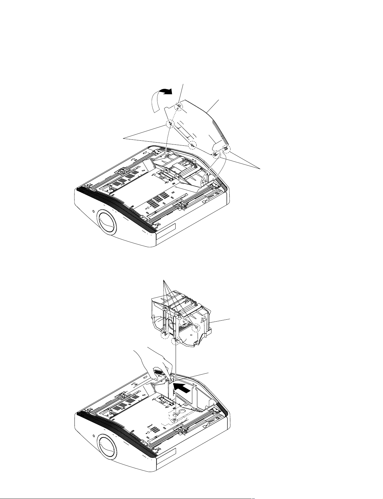
1-3-2. Lamp Cover
2
Two claws
1
Loosen screw.
(+PSW M4 x 12)
4
Remove the lamp cover
in the direction of the arrow.
3
Two claws
1-3-3. Lamp
1
Loosen four screws.
3
Lamp
2
Press the lamp stopper.
1-6
VPL-VW100
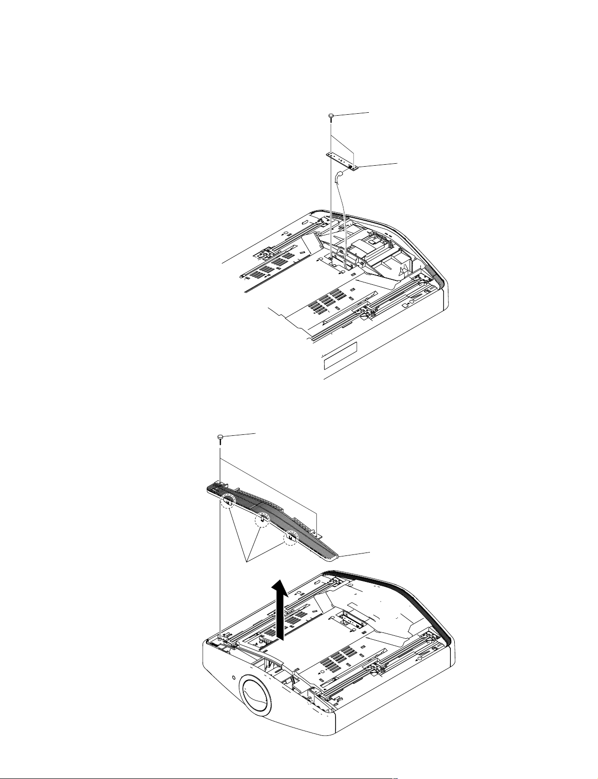
1-3-4. L Board
1
(+PSW M3 x 8)
CN10
Two screws
2
L board
1-3-5. Louver (F) Assembly
1
(+PSW M3 x 8)
2
Three claws
Two screws
3 Louver
(F) assembly
VPL-VW100
1-7
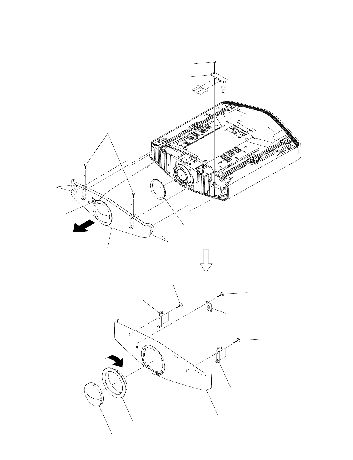
1-3-6 Front Cover Assembly and HB Board
5
(+PSW M3 x 8)
Screw
6 HB board
3
Two claws
NF board
1
Four screws
(+PSW M3 x 8)
A
4 Remove the front cover section
in the direction of the arrow A.
CN40
2
Two claws
CN83
7 Ring
CN80
CN81
(Lens)
1-8
Bracket (FR)
!\
B
8 Lens cap
!] Two screws
(+PSW M3 x 8)
9
Remove the front disk assembly by
turning it in the direction of arrow B.
0
Screw
(+PSW M3 x 8)
!-
NF board
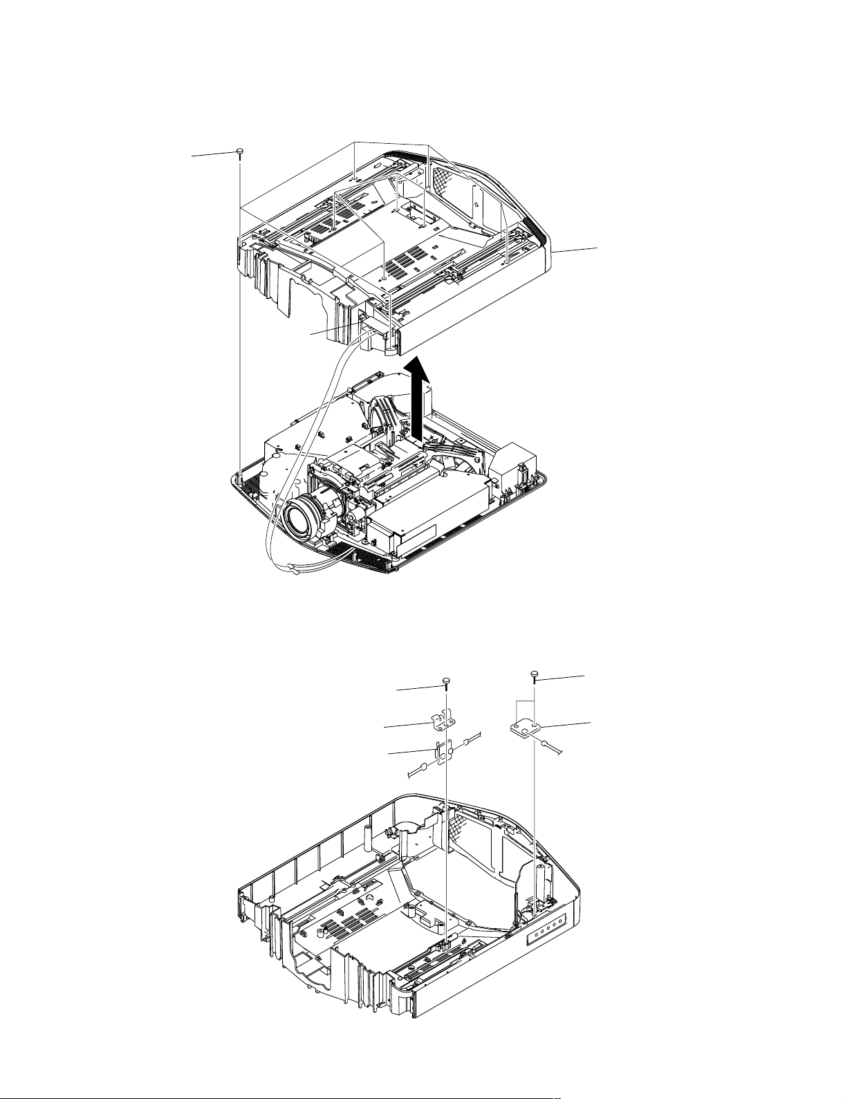
1-3-7. Hood Section
1
Ten screws
(+PSW M3 x 8)
HB board
2
Hood section
CN83
CN81
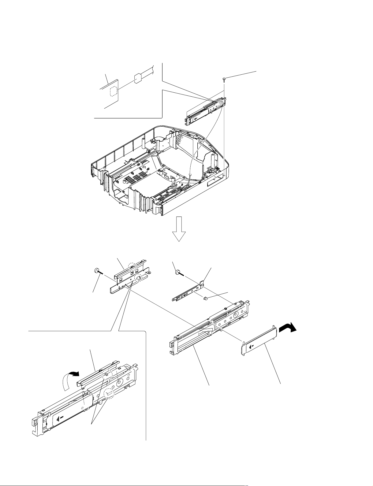
1-3-8. UA Board and UB Board
1
Screw
(+BV 3 x 12)
2
UA holder
3
UA board
CN26
CN25
4
Two screws
(+BV 3 x 12)
5
UB board
CN20
VPL-VW100
1-9
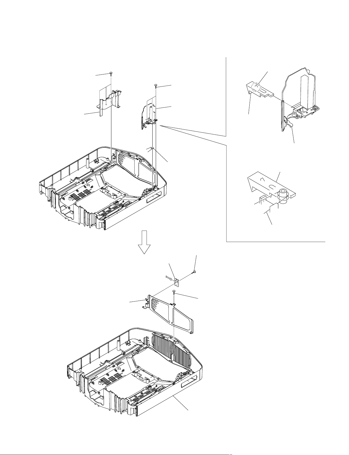
1-3-9. HA Block Assembly
HA board
CN60
CN60
1
Two screws
(+BV 3 x 12)
5
Shield plate (H)
2
Screw
(+BV 3 x 12)
4
Remove the shield plate (H)
in the direction of the arrow A.
A
3
Two claws
6
Screw
(+BVTP 3 x 12)
8
HA board
!/
HA block assembly
7
Button (+)
B
9
Remove the shield cover (H)
in the direction of the arrow B.
1-10
VPL-VW100
1-3-10. Hood Assembly and NR Board
4
Three screws
(+BV 3 x 12)
5
Rear duct (I)
1
Three screws
(+BV 3 x 12)
2
Rear duct (F),
Lamp stopper
3
Lamp stopper
spring
Lamp stopper
!=
!-
Claw
Lamp stopper
Rear duct (F)
7
Mesh (R)
9
CN50
NR board
8
Screw
(+PSW M3 x 8)
6
Screw
(+BV 3 x 12)
Lamp stopper spring
VPL-VW100
0
Hood assembly
1-11
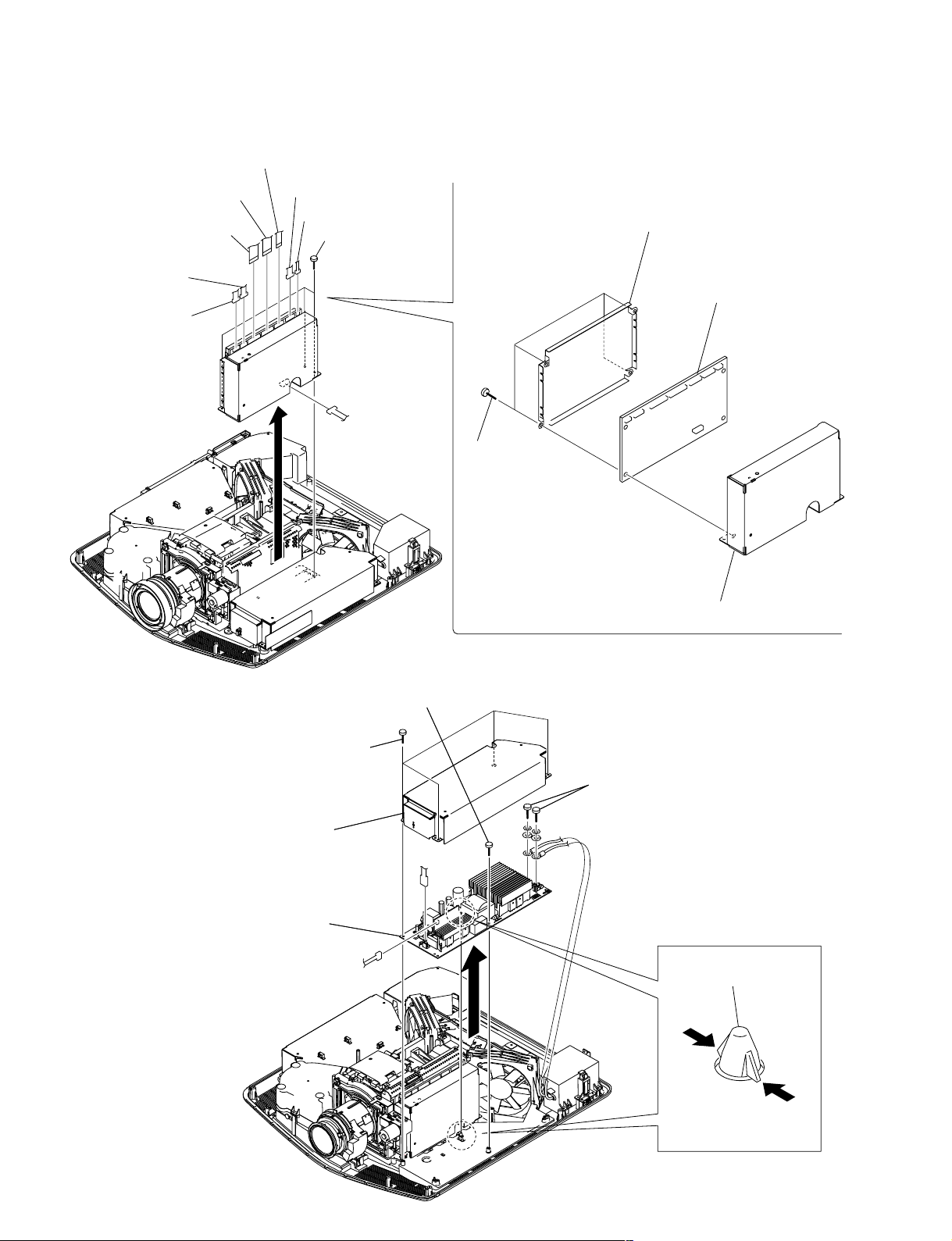
1-3-11. GB Board
Flat connector assembly
(32P) CN700
Flat connector assembly A
(24P) CN701
Flat connector assembly B
(24P) CN702
CN901
CN800
CN705
CN703
1
Three screws
(+PSW M3 x 8)
CN510
2
Four screws
(+PSW M3 x 8)
4
Shield cover (GB)
5
GB board
3
Shield case (GB)
1-3-12. Lamp Power Supply
1
Four screws
(+PSW M3 x 8)
2
Shield cover
(LP)
6
Lamp power supply
4
Screw
(+PSW M3 x 8)
J202
J101
JH2
JH1
3
Two screws
5 Spacer
, PCB
1-12
VPL-VW100
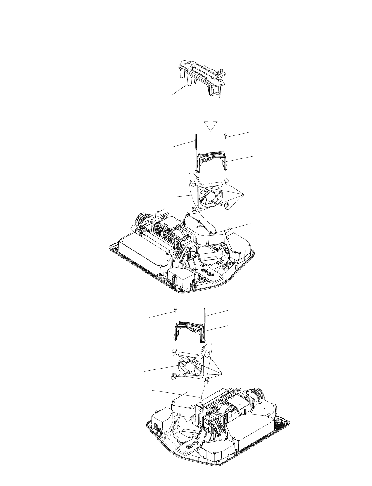
1-3-13. Optics Unit Assembly-1
1
Open the reuse clamp.
2
Remove the harness from the three claws.
Fan cover
(120MDL)
3
Three screws
(+PSW M3 x 8)
4
Fan cover
(120MDL)
C board
CN71
Flat connector assembly A
(24P) CN701
5
Fuse connector assembly
6
TL board
7
Thermo bracket
Flat connector assembly
(32P) CN700
VPL-VW100
CN100
Flat connector assembly B
(24P) CN101
Flexible flat cable
(41P) CN200
CN800
GB board
CN901
CN703
CN705
1-13
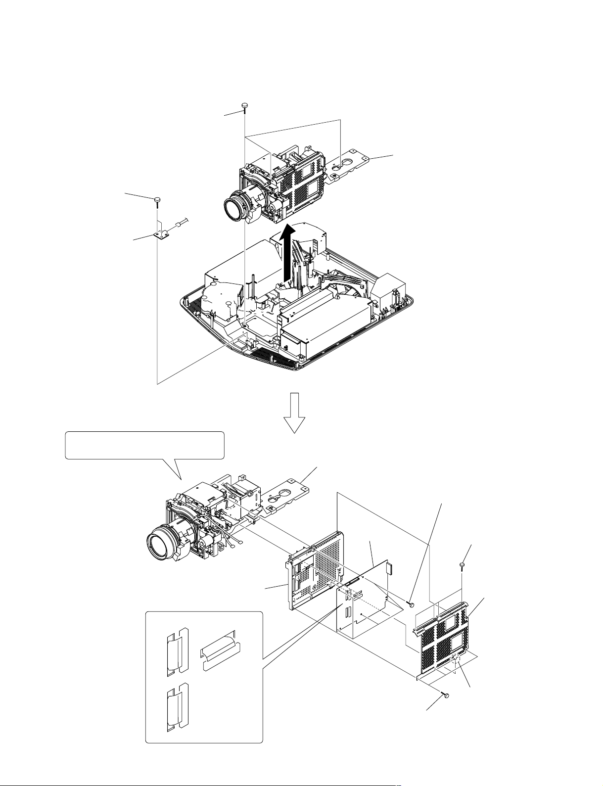
1-3-14. Optics Unit Assembly-2
1
Three screws
(+PSW M4 x 16)
!-Two screws
(+BV 3 x 12)
CN30
!= V board
Remove the optical unit assembly
2
in the direction of the arrow.
When replacing the optical unit assembly,
refer to Service Know-How (page 1-35).
9
C board holder
CN900 (B)
CN800 (G)
Optics unit assembly
0
8
C board
7
Five screws
(+PSW M3 x 8)
4
Four screws
(+PSW M3 x 8)
6
C board cover
1-14
CN700 (R)
3
Three screws
(+PSW M3 x 8)
5
Claw
VPL-VW100
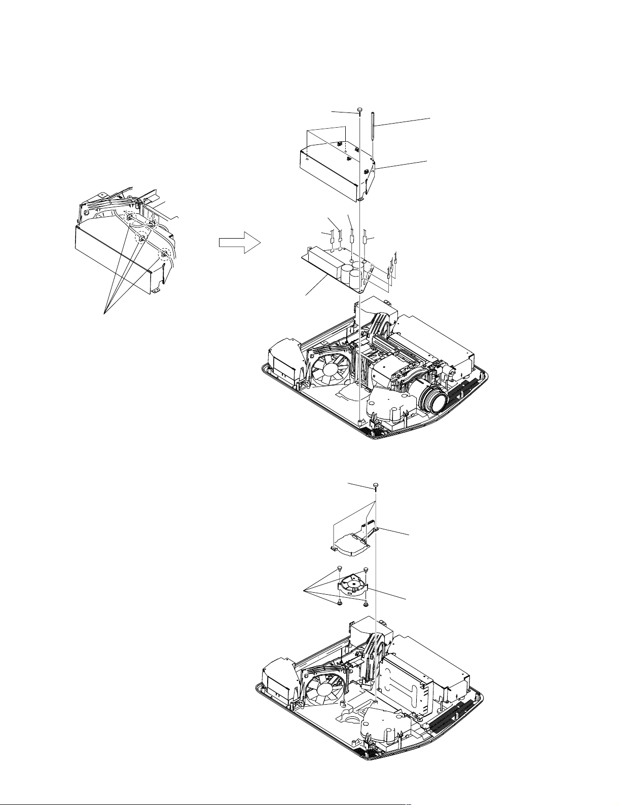
1-3-15. Igniter
1
Four screws
(+PSW M3 x 8)
2
Shield cover
(LP)
0
3
Igniter
Two screws
JH1
9
(+BV 3 x 12)
JH2
Three screws
4
Two screws
(+PSW M3 x 8)
5
Plug cover
7
Two lamp plug
6
Two screws
(+PSW 4 x 8)
8
Plug base
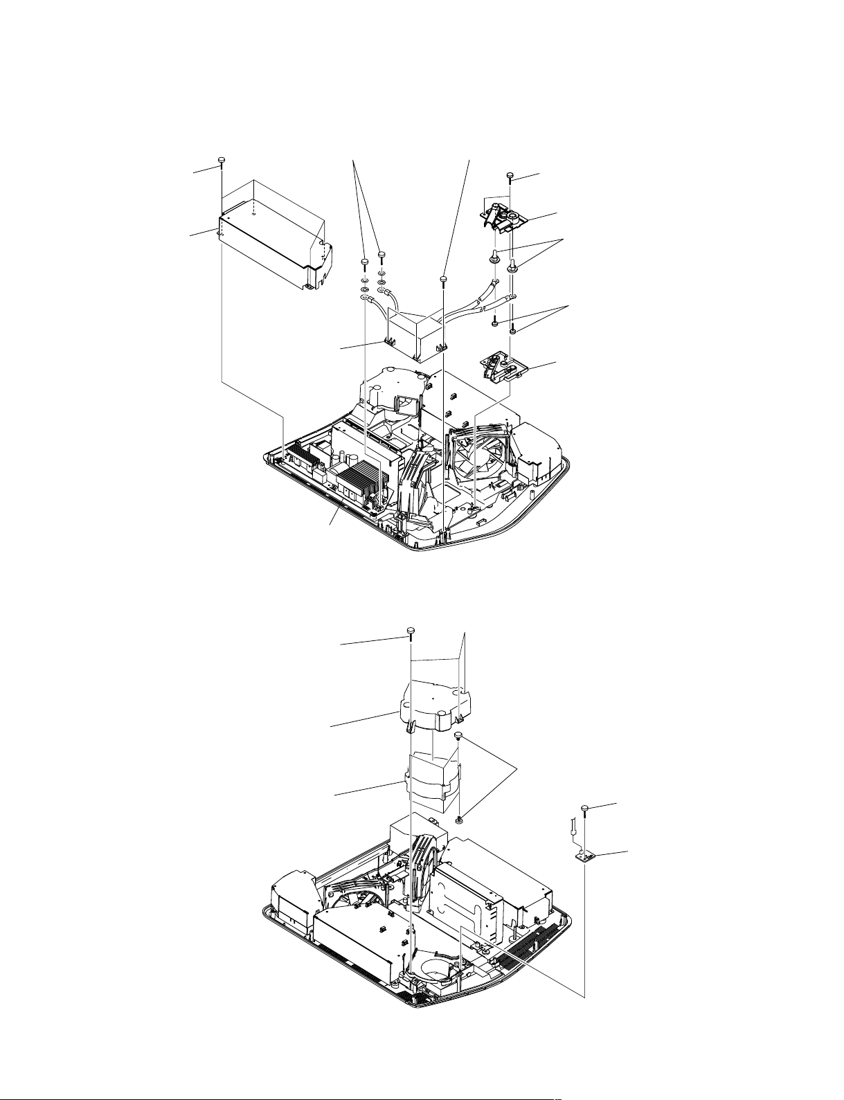
1-3-16. TA Board
Lamp power supply
1
Three screws
(+BV 3 x 12)
2
Fan cover
(84H)
4
D.C. motor
SFF22A/C-NP
3
Six fan dampers
CN70
5
Screw
(+BV 3 x 12)
6
TA board
VPL-VW100
1-15
1-3-17. D.C. Motor SFF21C/C-NP (Right) and D.C. Motor SFF21C/C-NP (Left)
For removal procedure,
refer to optics unit assembly-1.
1
Fan cover (120MDL),
Thermo bracket, etc.
4
Screw
D.C. Motor SFF21C/C-NP (Right)
3 S
pacer
7
D.C. Motor
SFF21C/C-NP (Right)
(+PSW M3 x 8)
5
6
Four fan cushions
2
Connector
Fan cover (120R) (Right)
D.C. Motor SFF21C/C-NP (Left)
1-3-18. GA Board
2
Three screws
(+PSW M3 x 8)
CN220
CN250
3
Spacer
4
Shield cover
(GA)
1
Four reuse clamps
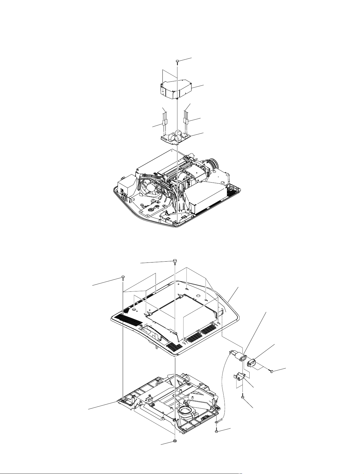
1-3-19. D.C. Fan (Sirocco)
CN200
5
GA board
1
Three screws
(+PSW M3 x 8)
TP200
CN221
CN310
CN301
VPL-VW100
3
Four fan dampers
2
Duct (PS)
4
D.C. Fan (Sirocco)
1-17
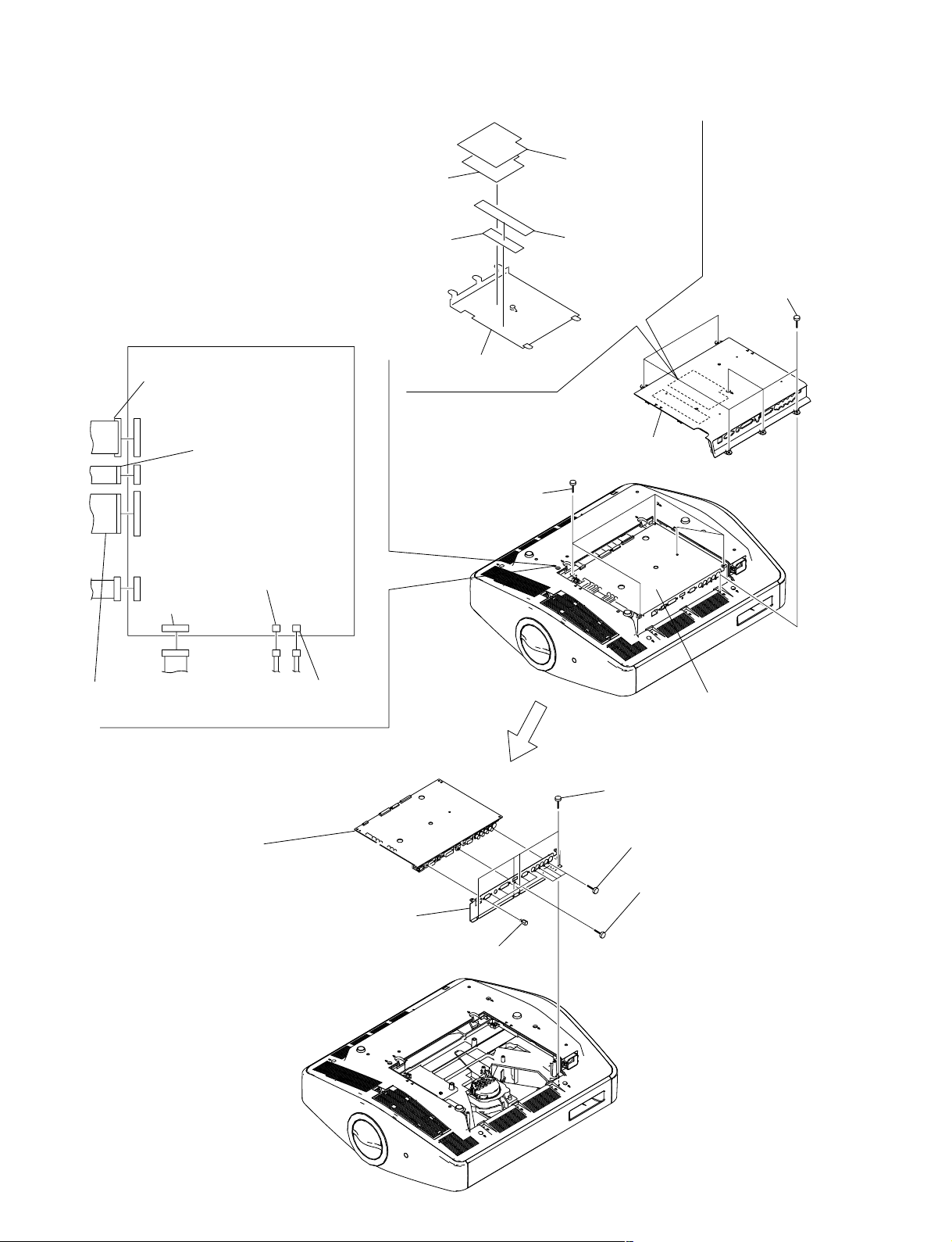
1-3-20. Q Board
Q board
Flexible flat cable
(41P)
3
EMC
sheet (Q1)
6
EMC sheet
(Q2)
7
Cover (Q)
4
Film (Q1)
5
Film (Q2)
1
Six screws
(+PSW M3 x 8)
CN1600
CN1812
CN701
CN1811
CN1803
Flat connector assembly A
(24P)
Flat connector assembly
(32P)
!] Q
board
CN1805
CN1801
Terminal plate
1-3-21. F Board
1
Two screws
(+PSW M3 x 8)
2
Shield case (F)
1-3-22. Bottom Cover Assembly
2
Adjustor assembly
TP1
CN001
CN002
TP4
3
F board
1
Seven screws
(+PSW M3 x 8)
0 Chassis
3
Two hexagon cap nuts
!- Bottom cover assembly
9
AC inlet
8
5
Bracket (AC)
4
Two screws
(+BV 3 x 12)
6
Screw
(+PSW M4 x 12)
Plug holder (A)
7
Two screws
(+B 3 x 12)
VPL-VW100
1-19
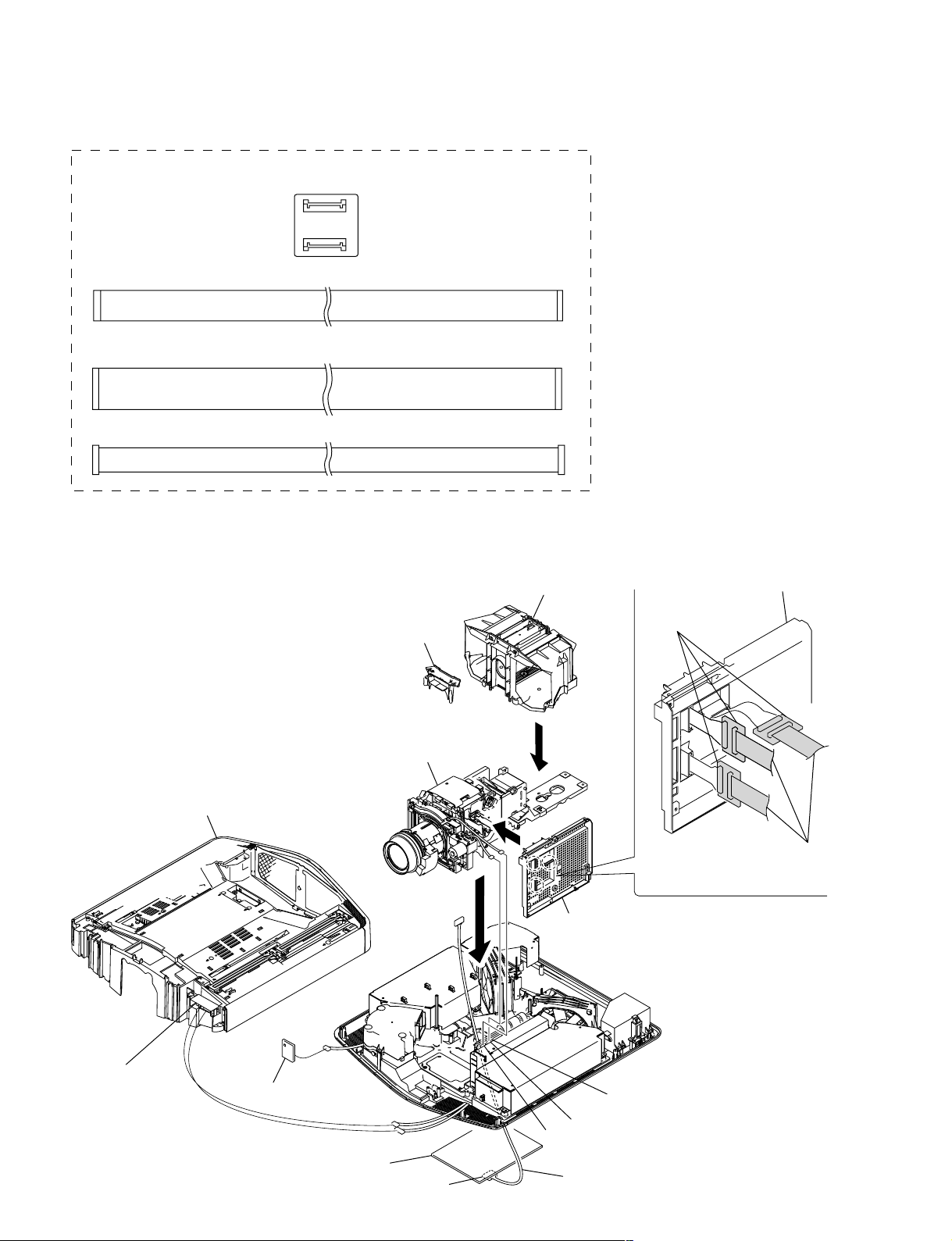
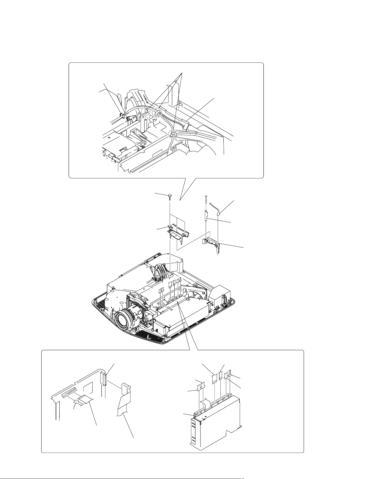
1-3-23. Extension Boards and Extension Cables
X kit assembly (A-1169-713-A)
Three XC boards
Flat cable (24P)
Three flat cables (50P) (There are 3 types of R, G and B. )
Connector cable (12P)
1-3-24. Extension Boards Connection
1. How to Assemble the Extension Boards and the Extension Cables
Lamp
Fan cover (120MDL),
Thermo bracket, etc.
C board holder
Three XC boards
1-20
HB board
Hood section
CN40
NF board
Optics unit assembly
CN83
CN81
Q board
CN1811
Three flat cables 50P
Install the C board holder.
GB board
CN901
CN800
Connector cable (12P)
VPL-VW100
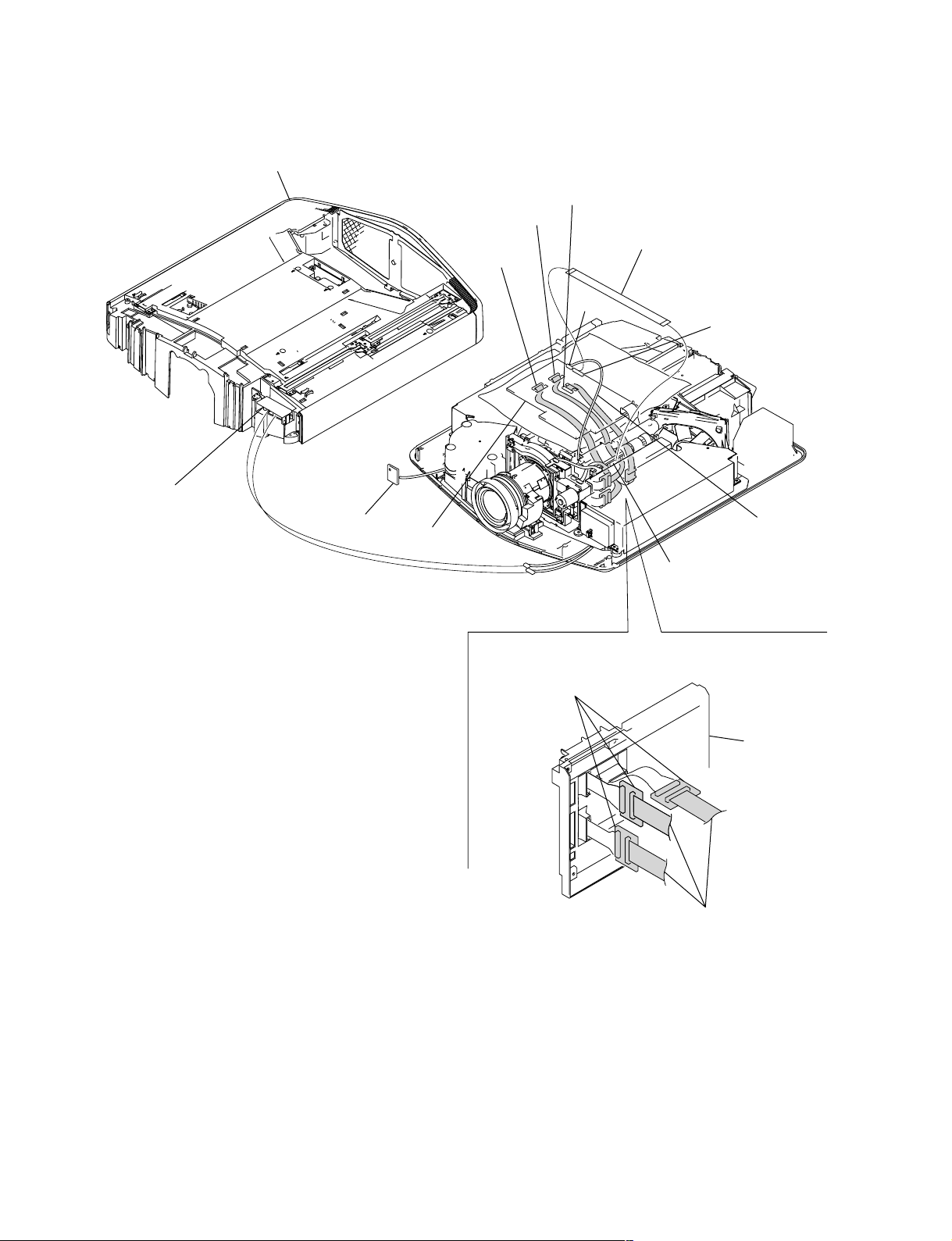
2. Connecting the Extension Boards and the Extension Cables
Hood section
CN800 (G)
CN900 (B)
CN700 (R)
HB board
NF board
C board
CN83
CN81
Flat cable (24P)
CN100
CN101
Connector cable (12P)
(From the Q board CN1811)
GB board
CN702 (24P)
Three XC boards
Three flat cables 50P
C board holder
VPL-VW100
1-21

1-4. Network
1-4-1. Overview
VPL-VW100 is equipped with the Network terminal. The user can check the projector status, and can
implement the various settings such as controls of the projector and setups of the Network block by using
the Web-browser.
In addition, it has dedicated functions for repair service such as the firmware update function via network,
the Event Trace function, and the network block reset function.
The firmware update function enables the user to upgrade the firmware such as the Network (Network
block) firmware, the Main (Main microcomputer) firmware and the Scaler (PixelWorks) firmware.
The Event Trace function enables the user to browse the information such as the logs (Lamp Timer Reset
log, Error log and Mail Report log) of the projector.
1-4-2. Service Preparation
(1) Connecting the Projector to the PC
To connect the projector to the PC directly, use the CAT5 cross-cable. Establish the network setups of the
projector and the PC so that the same subnet mask is set in both of the projector and the PC.
If the projector is connected to LAN, connect the PC to the same LAN and establish the Network setup of
the PC in accordance with the user’s LAN environment.
(2) Confirming the IP Address
Turn on the power of the projector, and have the Menu screen appear on the display. Confirm the IP
address of the projector on the [INFORMATION] screen.
1-22
VPL-VW100
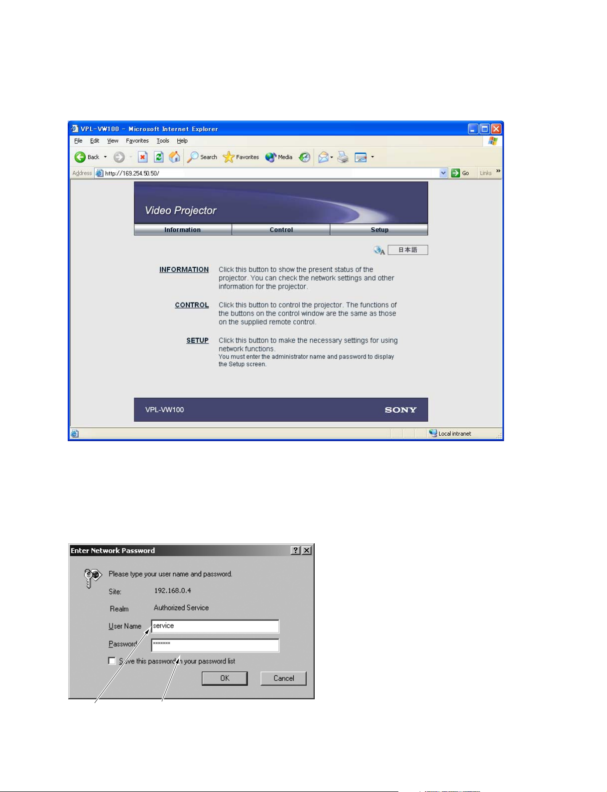
(3) How to Enter the Service Mode
To use the functions dedicated to the repair service, the user should enter the service mode. Type the
following address in the “Address” field of the Web-browser (IE5.0 or more) to enter the service mode.
Fig. 1 Index screen
When the user is prompted to enter the user name and the password, type them as follows.
User name : service
Password : vpl-vw100
If the user wants to move to another page from the service mode once, and then re-enter into it again, exit
the Web-browser and re-launch it.
User name : service Password : vpl-vw100
Fig.2 Password entry screen
VPL-VW100
1-23
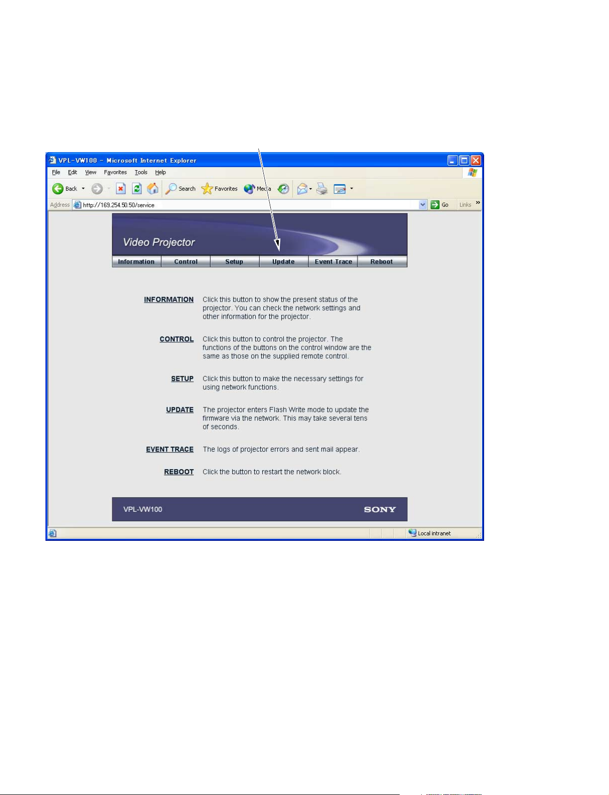
1-4-3. Firmware Update Function
(1) Update Preparation
Set the power of the projector in the standby state.
Click the [Update] tab shown on the Service web page.
1-24
Fig.3 Service screen.
VPL-VW100
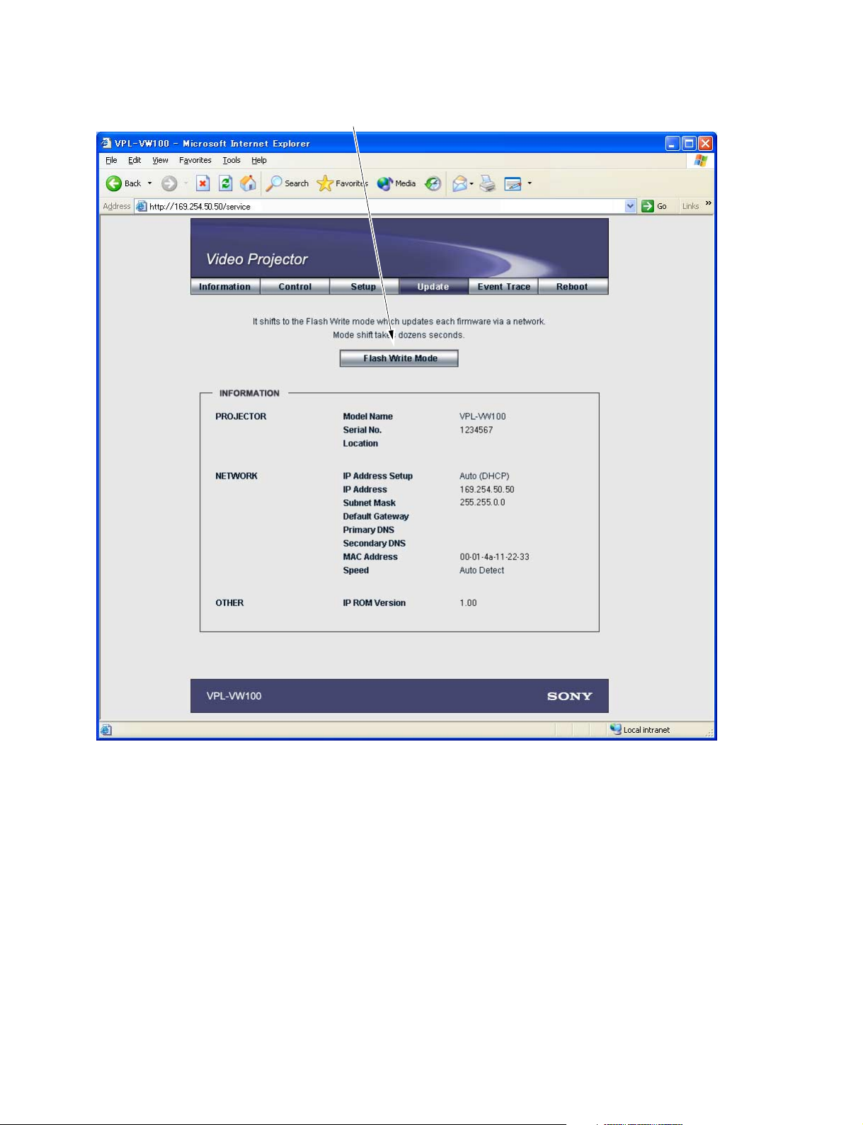
The Update screen will open. Then click [Flash Write Mode] .
Fig. 4 Upgrade screen
When the user clicks [Flash Write Mode], the Network block enters the upgrade ready state, and disables
the Web-browser not to be displayed. (The Web-browser displays an error indication.)
If the PC does not issue the upgrade requirement command for 15 minutes or more, the Network block
automatically exits the upgrade standby state and returns to the normal state after it is rebooted.
If version upgrade is executed, the Network block remains in the upgrade standby state unless the power
of the projector is turned off or the Network block is rebooted.
n
The upgrade requirement is issued at the moment when the [Update] button is clicked in the Firmware
Updater, which is described later.
The upgrade requirement is not issued if simply the Firmware Updater is launched.
VPL-VW100
1-25
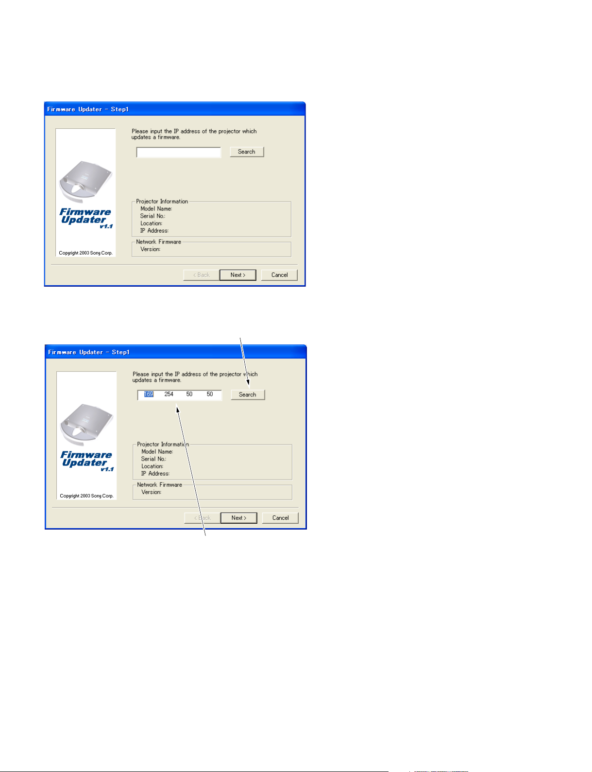
(2) Launching Firmware Updater
Launch “Firmware Updater.exe” on the PC.
Fig.5 Firmware Updater - Step1 screen (1)
(3) Specifying the Projector
Click the [Search] button to specify the projector whose firmware the client wants to upgrade.
If the IP address of the projector to be upgraded is already known,
it can be typed directly in this field.
(Delimit the IP address with a period.)
Fig.6 Firmware Updater - Step1 screen (2)
1-26
VPL-VW100
 Loading...