

Sony VPL-V800Q, VPL-V800QM Operating Instruction
3-858-857-11(1)
LCD Data Pr ojector
Operating Instructions
Mode d’emploi
Manual de instrucciones
EN
F
E
VPL-V800Q
VPL-V800QM
1997 by Sony Corporation
English
WARNING
To prevent fire or shock hazard, do not
expose the unit to rain or moisture.
To avoid electrical shock, do not open the
cabinet. Refer servicing to qualified
personnel only.
This symbol is intended to alert the
user to the presence of uninsulated
“dangerous voltage” within the
product’s enclosure that may be of
sufficient magnitude to constitute a risk
of electric shock to persons.
This symbol is intended to alert the
user to the presence of important
operating and maintenance (servicing)
instructions in the literature
accompanying the appliance.
For the customers in the United Kingdom
WARNING
THIS APPARATUS MUST BE EARTHED
IMPORTANT
The wires in this mains lead are coloured in accordance with
the following code:
Green-and-yellow : Earth
Blue : Neutral
Brown : Live
As the colours of the wires in the mains lead of this
apparatus may not correspond with the coloured markings
identifying the terminals in your plug proceed as follows:
The wire which is coloured green-and-yellow must be
connected to the terminal in the plug which is marked by the
letter E or by the safety earth symbol Y or coloured green or
green-and-yellow. The wire which is coloured blue must be
connected to the terminal which is marked with the letter N or
coloured black. The wire which is coloured brown must be
connected to the terminal which is marked with the letter L or
coloured red.
Voor de klanten in Nederland
Bij dit produkt zijn batterijen geleverd.
Wanneer deze leeg zijn, moet u ze niet
weggooien maar inleveren als KCA.
For the customers in the USA
This equipment has been tested and found to comply with
the limits for a Class A digital device, pursuant to Part 15 of
the FCC Rules. These limits are designed to provide
reasonable protection against harmful interference when the
equipment is operated in a commercial environment. This
equipment generates, uses, and can radiate radio frequency
energy and, if not installed and used in accordance with the
instruction manual, may cause harmful interference to radio
communications. Operation of this equipment in a residential
area is likely to cause harmful interference in which case the
user will be required to correct the interference at his own
expense.
You are cautioned that any changes or modifications not
expressly approved in this manual could void your authority
to operate this equipment.
For customers in Canada
This Class A digital apparatus meets all requirements of the
Canadian Interference-Causing Equipment Regulations.
The socket-outlet should be installed near the equipment
and be easily accessible.
2 (EN)
Table of Contents
Overview
Setting up and projecting
Adjustments and settings
using the menu
Precautions................................................................ 4 (EN)
Features ..................................................................... 6 (EN)
Location and Function of Controls ......................... 7 (EN)
Installing the Projector ........................................... 16 (EN)
Connecting with a Computer or a VCR................. 17 (EN)
Projecting................................................................. 18 (EN)
Using the MENU ...................................................... 21 (EN)
The INPUT SELECT Menu ...................................... 22 (EN)
Installation/connection
examples
Maintenance
The PICTURE AUDIO CTRL Menu ......................... 23 (EN)
The INPUT SETTING Menu..................................... 25 (EN)
The SET SETTING Menu......................................... 28 (EN)
The INPUT INFO Menu ............................................ 32 (EN)
Installation Examples ............................................. 34 (EN)
Floor Installation .................................................... 35 (EN)
Ceiling Installation ................................................. 36 (EN)
Connection Examples............................................. 37 (EN)
Connecting 15k RGB/Component Equipment....... 38 (EN)
Connecting the Switcher ........................................ 39 (EN)
Maintenance ............................................................ 40 (EN)
Replacing the Lamp ............................................... 40 (EN)
Cleaning the Air Filter ........................................... 40 (EN)
Troubleshooting...................................................... 41 (EN)
EN
English
Others
Specifications.......................................................... 43 (EN)
Index......................................................................... 49 (EN)
3 (EN)

Precautions
On safety
•Check that the operating voltage of your unit is identical with the voltage
of your local power supply. If voltage adaptation is required, consult with
qualified Sony personnel.
•Should any liquid or solid object fall into the cabinet, unplug the unit and
have it checked by qualified personnel before operating it further.
•Unplug the unit from the wall outlet or set the MAIN POWER switch to
OFF if it is not to be used for several days.
•To disconnect the cord, pull it out by the plug. Never pull the cord itself.
•The wall outlet should be near the unit and easily accessible.
•The unit is not disconnected from the AC power source (mains) as long
as it is connected to the wall outlet, even if the unit itself has been turned
off.
•Do not look into the lens while the lamp is on.
•Do not place your hand or objects near the ventilation holes — the air
coming out is hot.
On installation
On illumination
•When the projector is mounted on the ceiling, the Sony PSS-800
Projector Suspension Support must be used for installation.
•Allow adequate air circulation to prevent internal heat build-up. Do not
place the unit on surfaces (rugs, blankets, etc.) or near materials (curtains,
draperies) that may block the ventilation holes. Leave space of more than
30 cm (11
room heat rises to the ceiling; check that the temperature near the
installation location is not excessive.
•Do not install the unit in a location near heat sources such as radiators or
air ducts, or in a place subject to direct sunlight, excessive dust or
humidity, mechanical vibration or shock.
•To avoid moisture condensation, do not install the unit in a location
where the temperature may rise rapidly.
•To obtain the best picture, the front of the screen should not be exposed
to direct lighting or sunlight.
•Ceiling-mounted spot lighting is recommended. Use a cover over
fluorescent lamps to avoid lowering the contrast ratio.
•Cover any windows that face the screen with opaque draperies.
•It is desirable to install the projector in a room where floor and walls are
not of light-reflecting material. If the floor and walls are of reflecting
material, it is recommended that the carpet and wall paper be changed to
a dark color.
7
/8 inches) between the wall and the projector. Be aware that
4 (EN)

On preventing internal heat build-up
•After turning off the power, the cooling fan runs for about two minutes
while the POWER indicator flashes in green. The indicator flashes
quickly for the first minute. During that time, you will not be able to turn
the power back on with the POWER ON key.
•Do not press the MAIN POWER switch while the fan is still running.
Caution
The projector is equipped with ventilation holes (intake) at the bottom/
right side and ventilation holes (exhaust) at the front/left side on the rear.
Do not block or place anything near these holes, or internal heat build-up
may occur, causing picture degradation or damage to the projector.
On cleaning
•To keep the cabinet looking new, periodically clean it with a soft cloth.
Stubborn stains may be removed with a cloth lightly dampened with a
mild detergent solution. Never use strong solvents, such as thinner,
benzene, or abrasive cleansers, since these will damage the cabinet.
•Avoid touching the lens. To remove dust on the lens, use a soft dry cloth.
Do not use a damp cloth, detergent solution, or thinner.
•Clean the filter at regular intervals.
Overview
On repacking
•Save the original shipping carton and packing material; they will come in
handy if you ever have to ship your unit. For maximum protection,
repack your unit as it was originally packed at the factory.
5 (EN)

Features
High brightness, high picture quality
•High brightness
Adopting the 400 W, metal halide lamp and newly developed optical
system allow high brightness (light output 800 of ANSI lumen) and
excellent uniformity on the picture.
•High resolution
By using three 1.3-inch VGA
640 × 480 pixels for RGB input and 500 horizontal TV lines for
composite video input.
•Superior color reproduction
The superior characteristics of the metal halide lamp and the optical
design of the projector allow superior color reproduction.
Accepts various input signals
Adopting the scan converter allows this projector to detect various kinds of
inputs automatically and to project suitable picutres, such as the video,
component, VGA signal, or horizontal frequencies of 15 to 65 kHz and
vertical frequencies of 38 to120 Hz-RGB signal.
System expandability and versatility
The projector has the RS-422A interface connectors for communication.
By combining the optional IFB series interface boards and signal interface
switcher, VPL-V800Q/QM projection system can be greatly expanded.
This projector also has an index function for using multiple projectors in
one system.
1)
panels, this projector offers resolution of
Easy setup
•Easy setup with external equipment
This projector automatically recognizes the input signal and selects an
appropriate display mode from preset data held in the memory. You can
get an optimum picture by simply connecting an equipment.
•Flexible setup
The picture shift function allows you to install the projector in a wide
range of positions, without the worry of keystone distortion (the picture
going out of square). The power focus and power zoom functions also let
you change the size of the projection screen without having to move the
projector.
•Twin-stack compatible
The brightness of the image can be doubled by stacking two projectors.
.........................................................................................................................................................................................................
6 (EN)
1) VGA is a registered trademark of the International Business Machines Corporation, U.S.A.
Location and Function of Controls
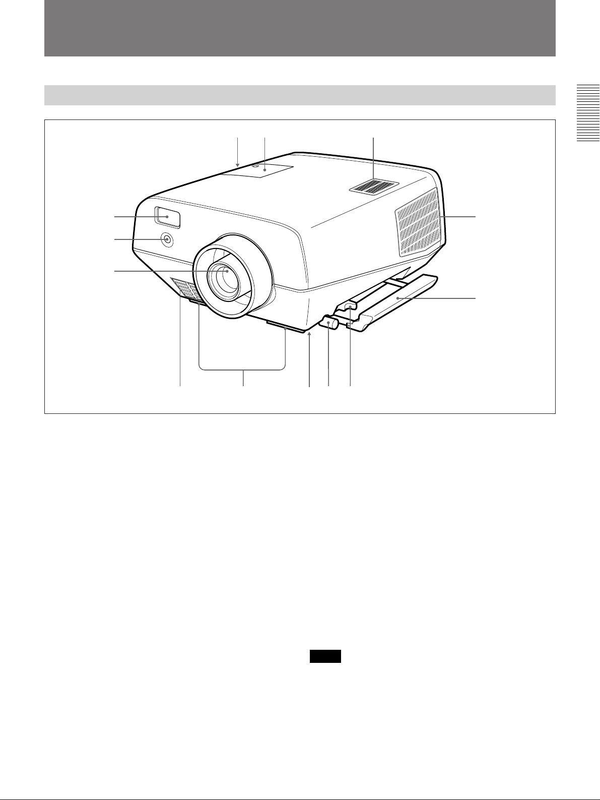
Front
!£ !™ !¡
1
2
3
54 876
1 Remote Commander pocket
Houses the supplied Remote Commander. When
inserting the Remote Commander, make sure the
infrared transmitter is facing forwards and push it until
it clicks.
To take out the Remote Commander from the pocket,
push it once and pull it out.
2 Front remote control detector
!º
9
8 Handle lever
Use the lever for putting away the carrying handle.
9 Carrying handle
Pull out the handle for carrying the projector.
0 Right side ventilation holes (exhaust)
Do not block the holes.
3 Lens
Remove the lens cap before projection.
4 Front ventilation holes (intake)
Do not place anything within the 50 cm (19
range from these holes or block them.
5 Adjusters
Use the adjusters to keep the projector level if it is
installed on an uneven surface.
6 Bottom ventilation holes (exhaust)
Do not block the holes.
7 Adjuster screw
Adjusts the height of the adjuster.
3
/4 inches)
!¡ Speaker
!™ Lamp cover
!£ Left side ventilation holes (intake)
Do not place anything within the 30 cm (11
range from these holes or block them.
Notes
•Do not block the ventilation holes, or internal heat
build-up may occur, causing fire or damage to the
projector.
•Do not place anything near the ventilation holes or
touch these holes as it may cause internal heat buildup.
7
/8 inches)
7 (EN)
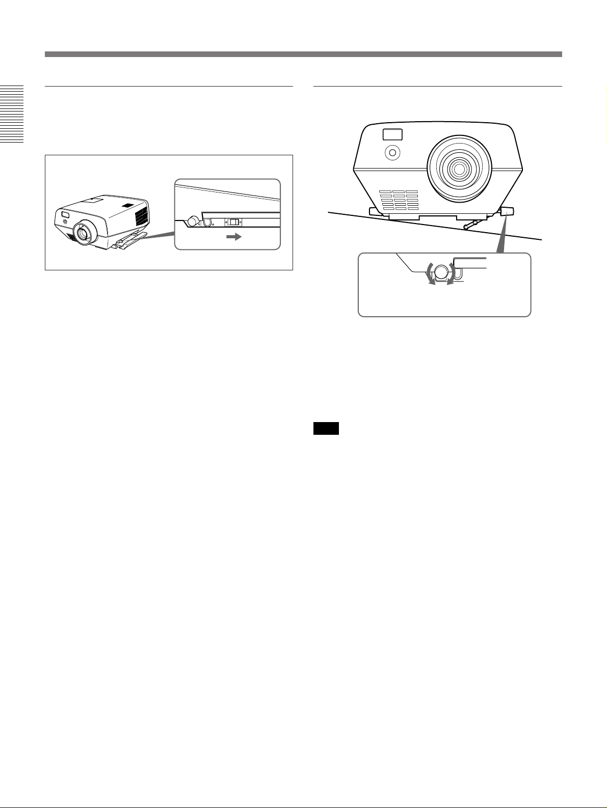
Location and Function of Controls
Using the carrying handles
Pull out to use for carrying the projector. To put away
the handle, slide the handle lever backward.
Using the adjusters
To raise
the projector
When turning the screw counterclockwise,
the adjuster comes out.
To lower
the projector
1 While lifting the projector, turn the screw
counterclockwise.
The adjuster comes out.
2 Turn the screw to adjust the height so that the
projector becomes level.
Note
Be careful not to let the projector down on your
fingers.
8 (EN)
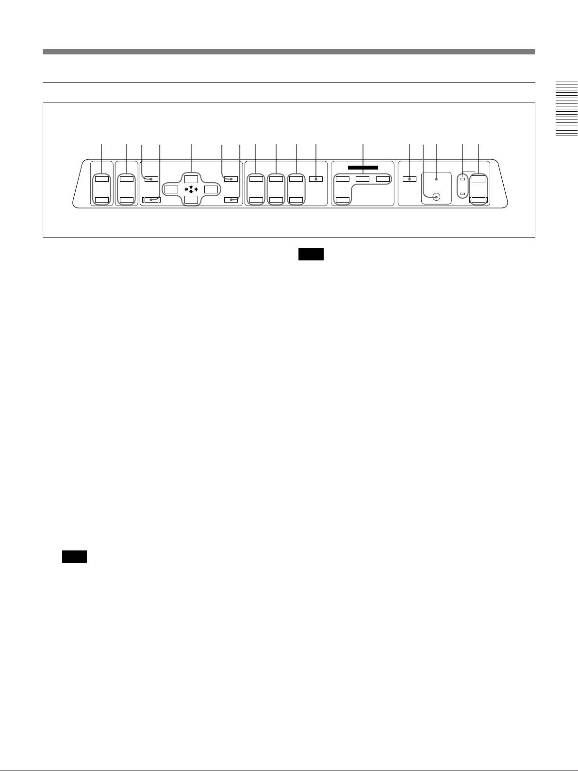
Control panel
!∞ !¢ !™ 4!¡
MUTING
VOLUME
PICTURE
AUDIO
MEMORY
+
–
RESET
MENU
ENTER
SHIFT
+
–
1 POWER keys
ON : Press to turn on the power when the projector is
in the standby mode. The POWER indicator lights
in green when the power is turned on.
OFF : Press to turn off the power.
2 Indicators
POWER: Lights in green when the power is turned
on.
Flashes in green while the cooling fan runs after
turning off the power with the POWER OFF key.
The fan runs for about two minutes after turning
off the power.
The POWER indicator flashes quickly for the first
minute. During this time, you will not be able to
turn the power back on with the POWER ON key.
STANDBYu: Lights in red when the MAIN
POWER switch at the rear of the projector is
turned on.
Once in the standby mode, you can turn on and off
the projector with the POWER ON/OFF keys on
the Remote Commander or the control panel.
Note
When the MAIN POWER switch is turned off,
there will be a slight delay before the STANDBY
indicator goes off.
3 Error code display window
Displays the error codes.
For details on the error codes, see “Error codes” on page
42 (EN).
LENS CONTROL
ZOOM
+
–
PATTERNFOCUS
+
–
VIDEO
SELECT
INPUT SELECT
A
VIDEO/S VIDEO
LIGHTB
STANDBY u
g
Note
When the lamp is warm, it may not light up easily.
In this case, 88 appears in the error code display
window, but this is not malfunction.
If 88 remains lit for more than three minutes after
turning on the power, never open the lamp cover if
the projector is installed on the ceiling.
4 Rear remote control detector
5 LIGHT key
Lights the back lighting for the keys on the control
panel when the projector is turned on. Press again to
turn off the back lighting. If you do not press any key
for 30 seconds, back lighting turns off automatically.
6 INPUT SELECT keys
Select the input signal.
VIDEO: Selects the video signal input from the
VIDEO or S VIDEO connectors and the audio
signal input from the AUDIO IN L/R jacks. To
switch the S VIDEO and VIDEO connectors, use
the SELECT key.
SELECT: Each time you press this key, the input
video signal is switched between the VIDEO and
S VIDEO connectors.
A: Selects the audio and video signals input from the
INPUT A connectors.
B: Selects the signal input from the connectors on the
optional interface board (other than IFB-40) which
is installed in the INPUT B section.
7 PATTERN key
Displays an H pattern on the screen for focus, zoom,
and shift adjustments. Press again to clear the H
pattern.
1237 5!¶ !§ !º 69 8!£
POWER
ON
OFF
(Continued)
9 (EN)

Location and Function of Controls
8 FOCUS +/– keys
Adjusts the focus.
+ : Picture focuses forward.
– : Picture focuses farther back.
9 ZOOM +/– keys
Adjusts the zoom.
+ : Picture size is enlarged.
– : Picture size is reduced.
0 SHIFT +/– keys
Adjusts the vertical position of the picture.
+ : Picture moves upward.
– : Picture moves downward.
!¡ ENTER key
Press to enter the settings of items in the menu system.
!™ MENU key
Press to display the on-screen menu. Press again to
clear the menu.
!£ Arrow keys (V/v/B /b)
Used to move the on-screen cursor or to make various
adjustments.
!¢ RESET key
Press to restore the value of an item back to its factory
preset value. This key functions when the menu or a
setting item is displayed on the screen.
!∞ MEMORY key
Stores various adjustment data into memory.
!§ VOLUME +/– keys
Adjust the volume of the built-in speaker and output
level of the AUDIO OUT jacks.
+ : Increases the volume.
– : Decreases the volume.
!¶ MUTING keys
Cuts off the picture or sound temporarily.
PICTURE: Press to cut off the picture. Press again
to restore the picture.
AUDIO: Press to cut off the sound. Press again or
press the VOLUME + key to restore the sound.
10 (EN)
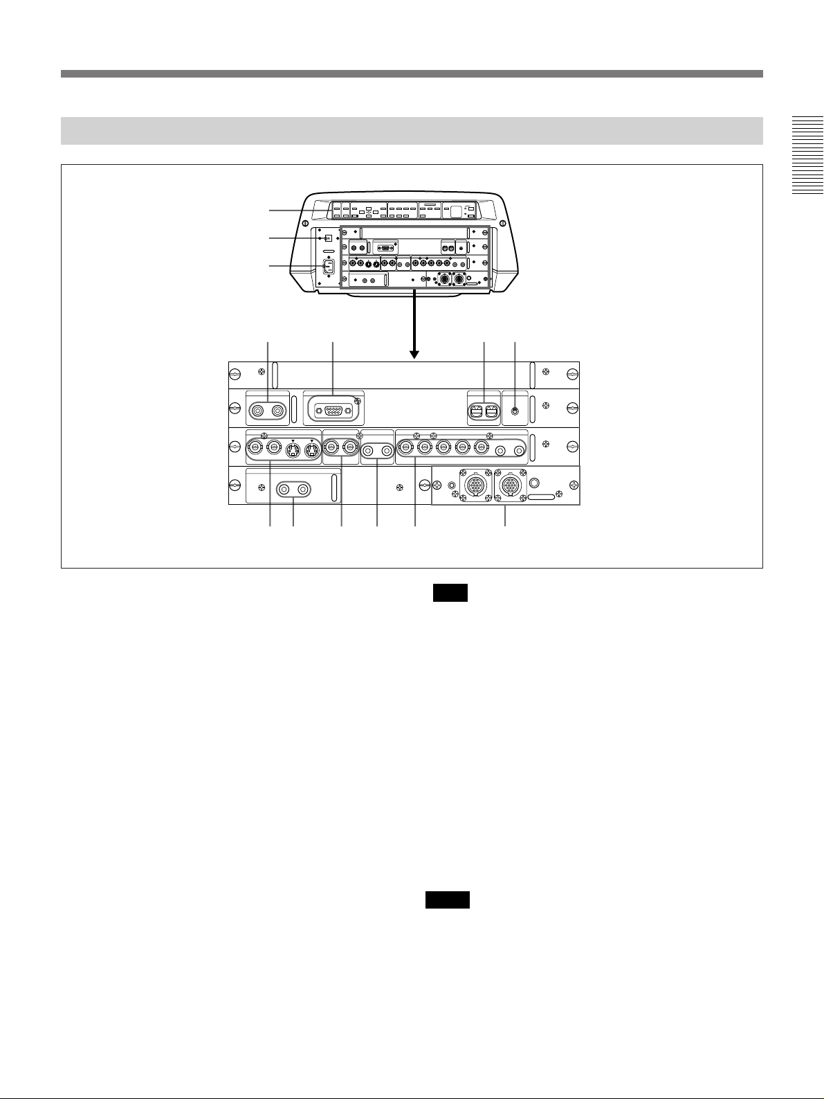
Rear
+
1
2
–
U
3
45 67
CONTROL S
IN
PLUG IN
POWER
OUT
S VIDEO
AUDIO OUT
L R
REMOTE
RS-422A
VIDEO
AUDIO IN INPUT A
L R
8 9 !º !¡ !™
1 Control panel
You can turn the control panel by 180 degrees when
installing the projector upside-down, such as for
ceiling installation. For details, consult with qualified
Sony personnel.
For details on the control panel key arrangement, see
“Control panel” on pages 9 (EN) and 10 (EN).
2 MAIN POWER switch (OON/oOFF)
Turns the main power on and off.
3 AC IN socket
Connect the supplied AC Power cord.
4 CONTROL S IN/OUT jacks (stereo minijack)
Connect to the control S jacks of other Sony
equipment.
CONTROL S IN/PLUG IN POWER (DC 5 V
output) jack: Connects to the CONTROL S OUT
jack of the supplied Remote Commander when
using as a wired Remote Commander. In this case,
you do not need to install the batteries in the
Remote Commander, since the power is supplied
from this jack.
CONTROL S OUT jack: Outputs the control S
signal.
+–+–+
–
G/Y B/B-Y SYNC/HDY IN C IN IN OUT IN OUT VD AUDIO IN
R/R-Y
0 0
REMOTE 1
g
IN
u
INDEX TRIG
0
0
R
L
(MONO)(MONO)
MODE
OUT
!£
Note
When connecting the remote commander cable to the
CONTROL S IN jack, the remote control detectors
will not work.
5 REMOTE RS-422A connector (D-sub 9-pin,
female)
Connect to a computer to operate the projector from a
computer. This expands system capability via the RS422A interface. Before using this connector, remove
the red cap attached at the factory.
6 INDEX switches
Set the index number of the projector when using
multiple projectors. You can set the numbers between
“01” and “99”. It is set to “01” at the factory.
Notes
•Do not set the index number to “00”. If it is set to
“00”, the projector cannot be controlled with the
Remote Commander.
•Do not set the index number to “9” if you use the
supplied Remote Commander for controlling the
projector.
(Continued)
11 (EN)
Location and Function of Controls
7 TRIG (trigger output) jack (monaural minijack)
The signal is transmitted from this jack to the
connected equipment whether the projector is on or
off. (This is not a power source for external
equipment.) A singal of approximately 5 V DC is
output when the projector power is on. The signal is
not output when the projector power is off.
8 S VIDEO connectors
Connect to external video equipment, such as a VCR.
The OUT connector can be used as loop-through
output via the Y/C IN or IN connectors.
Y IN/C IN (BNC-type): Connect to the Y and C
video outputs of the video equipment.
IN (mini DIN 4-pin): Connects to the Y/C video
output of the video equipment.
OUT (mini DIN 4-pin): Used as loop-through output
via the Y/C IN connectors or the IN connector.
Note
If you have video equipment connected to both the Y/
C IN and IN connectors, the signal from the Y/C IN
connectors are selected prior to the IN connector.
When showing a video connected to the IN connector,
be sure not to connect any cable to the Y/C IN
connectors.
9 AUDIO OUT L/R jacks (phono type)
Connect to external active speakers.
The volume of the speakers can be controlled by the
VOLUME keys on the Remote Commander or the
control panel.
0 VIDEO connectors (BNC-type)
Connect to external video equipment, such as a VCR.
The VIDEO OUT connector can be used as loopthrough output via the VIDEO IN connector.
IN: Connects to the composite video output
connector of the video equipment.
OUT: Used as loop-through output of the VIDEO IN
connector.
!™ INPUT A connectors
RGB input connectors (R/R-Y, G/Y, B/B-Y,
SYNC/HD, VD) (BNC-type): Connect to such as
the video outputs of a computer or a video camera.
According to the connected equipment, the RGB
or component (R-Y, Y, B-Y) signal is selected.
AUDIO IN L (MONO) /R jacks (phono type):
Connect to the audio output jacks of equipment.
For stereo equipment, use both the L and R jacks;
for monaural equipment, use the L (MONO) jack
only.
!£ Signal interface board attachment part (INPUT
B)
The IFB-40 Signal Interface Board is installed at the
factory. Other optional signal interface boards can be
attached to this section instead of the IFB-40.
For details on installing the interface boards, consult with
qualified Sony personnel.
Indicator (red): Lights up when the REMOTE 1 IN
connector is selected.
REMOTE 1 IN connector (14-pin multi-
connector): Connect to the optional signal
interface switcher. When using two projectors and
this unit is used as the first one, connect to the
REMOTE 1 OUT connector on the IFB-40
installed on the other projector.
REMOTE 1 OUT connector (14-pin multi-
connector): Connect to the REMOTE 1 IN
connector on IFB-40 installed on another projector
when using two projectors and this unit is used as
second one.
MODE selector: Turn the control switch of the
MODE selector to the appropriate position
according to the length of the cable connecting to
the REMOTE 1 OUT connector.
Cable length up to 2 m
Type of cable SIC-M-1 SIC-M-5 SIC-M-15 SIC-M-50
CCQ-2BRS CCQ-10BRS
Position 1 2 3 4
up to 10 m up to 25 m up to 50 m
CCQ-5BRS CCQ-25BRS CCQ-50BRS
SIC-M-25
!¡ AUDIO IN L (MONO) /R jacks (phono type)
Connect to the audio output jacks of equipment. For
stereo equipment, use both the L and R jacks; for
monaural equipment, use the L (MONO) jack only.
12 (EN)
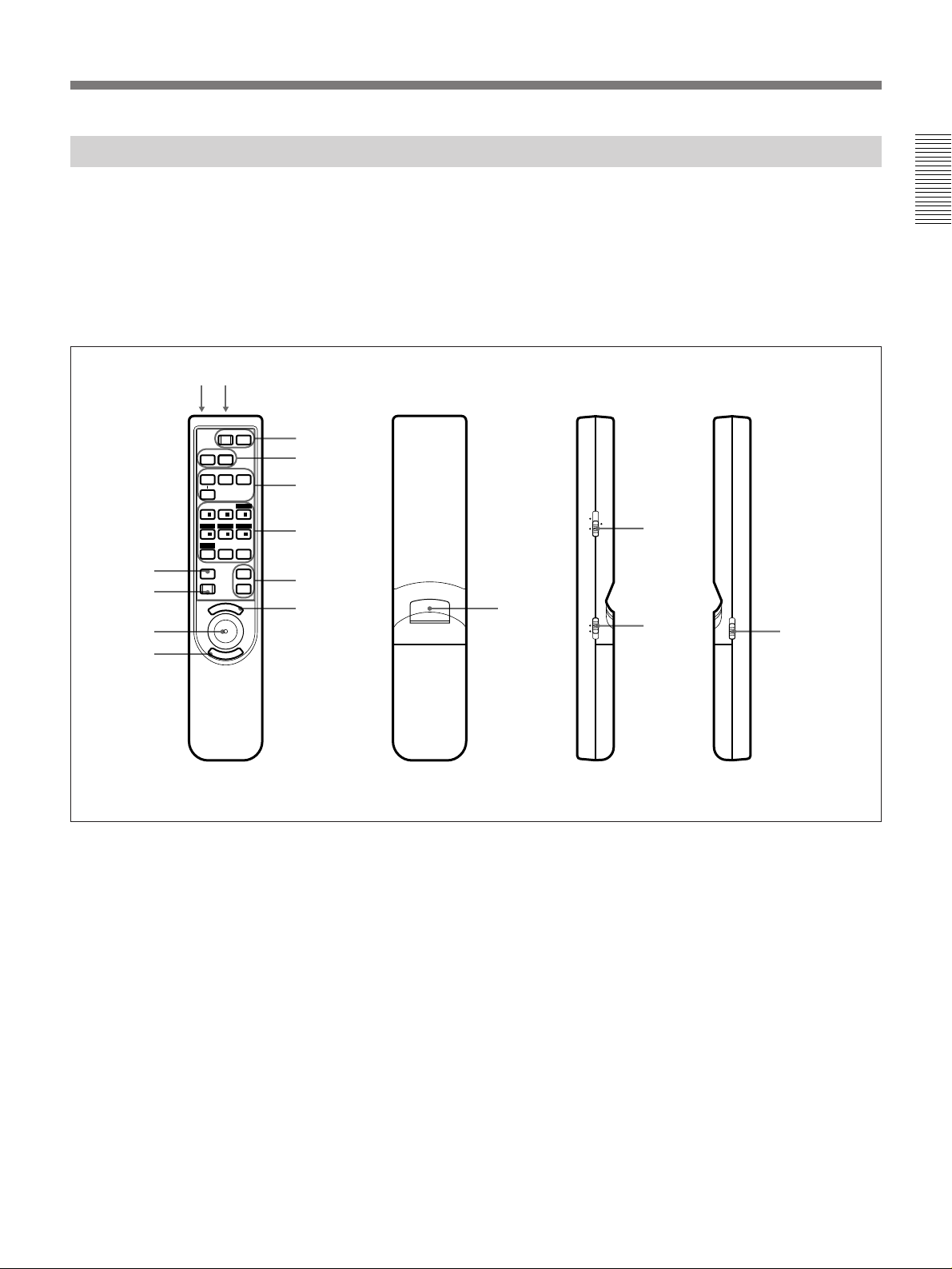
Remote Commander
The Remote Commander can be used as a wireless or
wired Remote Commander. The functions of the keys
on the Remote Commander are the same as those on
the control panel of the projector.
For details on control panel keys on the projector, see pages
9 (EN) and 10 (EN).
!™ !£
POWER
OFF
!¡
!º
MUTING
AUDIO
INPUT SELECT
SELECT
VIDEO/S VIDEO
SWITCHER
+
1/
4/ – 5/ – 6/
PATTERN
MEMORY
RESET
M
PIC
AVIDEO
2/ + 3/
ZOOMSHIFT
87 ALL
E
ON
B
/ LENS /INDEX
+
FOCUS
–
SECOND
+
VOLUME
–
N
U
1
2
3
5
6
7
9
E
R
N
E
8
T
If you use the optional RM-PJ20/PJ21 Mouse
Receiver, you can use the Remote Commander as a
mouse for a connected computer.
For details, refer to the instruction manual supplied with the
RM-PJ20/PJ21 Mouse Receiver.
INDEX
LENS SWITCHER
8
MOUSE MENU
4
!¢
LIGHT
!∞
Front Rear Side (R) Side (L)
1 POWER ON/OFF keys
2 MUTING PIC/AUDIO keys
The MUTING PIC key has the same function as the
MUTING PICTURE key on the control panel.
3 INPUT SELECT/ VIDEO/A/B/SELECT keys
4 SWITCHER/INDEX/LENS selector
Switches the function of the SWITCHER/INDEX/
LENS keys.
SWITCHER: For designating the input from the
optional switcher.
INDEX: For selecting the projector to be operated
when multiple projectors are used in one system.
LENS: For adjsting the focus, zoom, shift, and
displaying or clearing the H pattern.
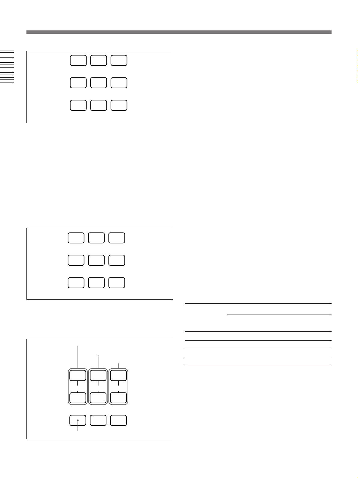
5 SWITCHER/INDEX/LENS keys
These keys function as follows depending on the
position of the SWITCHER/INDEX/LENS selector.
When the SWITCHER/INDEX/LENS selector is
set to SWITCHER position
Designate the input from the switcher when the
optional signal interface switcher is connected. The
SECOND key is used when two switchers are
connected. To select the input from the second
switcher, press a number key between 1 and 8 within
two seconds after pressing the SECOND key.
(Continued)
13 (EN)
Location and Function of Controls
1
23
6 VOLUME +/– keys
7 MENU key
4
Designate the input from the switcher.
56
SECOND
87
When the SWITCHER/INDEX/LENS selector is
set to INDEX
Used to designate the projector to be operated when
multiple projectors are used in one system.
You can designate the projector by pressing the index
number which you have set on the projector.
Example: When pressing [5] first and then [ENTER],
the next operation will be effective only on
the projector on which the index number
has been set to “5”. When operating all the
projectors at the same time, press [ALL]
first, then [ENTER].
1 23
4
Designate the projector to be operated.
56
87 ALL
8 ENTER keys
9 Joy stick
Used to move the on-screen cursor or to make various
adjustments.
0 RESET key
!¡ MEMORY key
!™ CONTROL S OUT jack (stereo minijack)
Connect to the CONTROL S IN jack on the projector
when using the Remote Commander as a wired
Remote Commander. In this case, you do not need to
install the batteries since the power is supplied from
the CONTROL S IN jack on the projector.
!£ Infrared transmitter
!¢ MOUSE/MENU switch
Normally, set to MENU. Set to MOUSE when you
operate the mouse function of a computer connected to
the optional RM-PJ20/PJ21 Mouse Receiver from the
Remote Commander.
When the MOUSE/MENU switch is set to MOUSE,
the MENU, ENTER keys, and joy stick function as
follows.
1)
Function
2), 3)
Macintosh
4)
When the SWITCHER/INDEX/LENS selector is
set to LENS
Used to adjust focus, zoom, shift and to display or
clear the H pattern on the screen.
Adjust the shift.
Adjust the zoom.
Adjust the focus.
+
–
PATTERN
Displays or clears the H pattern.
++
FOCUSZOOMSHIFT
––
Key
IBM PC/AT
compatible, NEC
MENU Left button Mouse button
ENTER (front) Right button Mouse button
ENTER (rear) Right button Mouse button
Joy stick
Corresponds with the movements of the mouse
!∞ LIGHT switch
Lights the back lighting for the keys on the Remote
Commander. Press again to turn off the back lighting.
If you do not press any key for 30 seconds, back
lighting turns off automatically.
..........................................................................................................................................................................................................
1) IBM PC/AT is a registered trademark of International Business Machines Corporation, USA.
2) NEC is a registered trademark of NEC Corporation.
14 (EN)
3) RM-PJ21 does not function with NEC computers.
4) Macintosh is a registered trademark of Apple Computer, Inc.
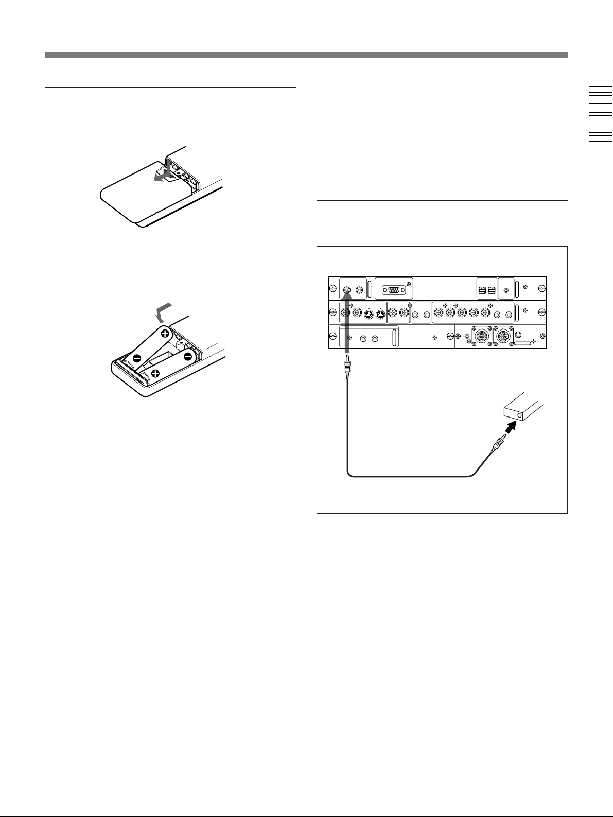
Battery installation
1 Push and slide to open the lid.
•The remote control detectors on the projector do not
operate when connecting the remote commander
cable to the CONTROL S IN jack. If you wish to use
the Remote Commander as a wireless Remote
Commander, be sure to remove the remote
commander cable from both the Remote Commander
and the projector.
To connect the Remote Commander to the
projector
2 Install the two size AA (R6) batteries (supplied)
with the correct polarity.
Be sure to install
the battery from
the ’ side.
3 Replace the lid.
Notes on batteries
•Be careful that the battery orientation is correct when
inserting batteries.
•Do not mix old battery with new one, or different
types of batteries.
•If you do not intend to use the Remote Commander
for a long time, remove the batteries to avoid damage
from battery leakage. If a battery has leaked, remove
the batteries, wipe the battery compartment dry and
replace the batteries with new ones.
Notes on wireless Remote Commander
operation
•Be sure that there is nothing to obstruct the infrared
beam between the Remote Commander and the
projector.
•The operation range is limited. The shorter the
distance between the Remote Commander and the
projector, the wider the angle within which the
commander can control the projector.
Rear
CONTROL S
OUT
IN
PLUG IN
POWER
to CONTROL S IN
Stereo remote
commander cable
(supplied)
S VIDEO
AUDIO OUT
L R
REMOTE
RS-422A
VIDEO
AUDIO IN INPUT A
L R
G/Y B/B-YSYNC/HDY IN C IN IN OUT IN OUT VD AUDIO IN
R/R-Y
REMOTE 1
IN
to CONTROL
S OUT
INDEX TRIG
0
0
R
L
(MONO)(MONO)
MODE
OUT
Remote Commander
Note on wired Remote Commander operation
using the supplied stereo remote commander
cable
If the MOUSE/MENU switch is set to MENU to
operate the projector, you do not need to install the
batteries since the power is supplied from the
CONTROL S IN jack on the projector. In this case, the
batteries are not consumed.
15 (EN)
 Loading...