

Sony VPL-TX70 User Manual
Data
Projector
4-148-278-13 (1)
Operating Instructions
Before operating the unit, please read this manual thoroughly
and retain it for future reference.
VPL-TX70
VPL-TX7
Not all models are available in all countries and area. Please check
with your local Sony Authorized Dealer.
© 2009 Sony Corporation

WARNING
To reduce the risk of fire or electric
shock, do not expose this apparatus
to rain or moisture.
To avoid electrical shock, do not open
the cabinet. Refer servicing to
qualified personnel only.
WARNING
THIS APPARATUS MUST BE
EARTHED.
IMPORTANT
The nameplate is located on the bottom.
WARNING
When installing the unit, incorporate a
readily accessible disconnect device in the
fixed wiring, or connect the power plug to an
easily accessible socket-outlet near the unit.
If a fault should occur during operation of
the unit, operate the disconnect device to
switch the power supply off, or disconnect
the power plug.
CAUTION
Danger of explosion if battery is incorrectly
replaced.
Replace only with the same or equivalent
type recommended by the manufacturer.
When you dispose of the battery, you must
obey the law in the relative area or country.
For the customers in the U.S.A.
This equipment has been tested and found to
comply with the limits for a Class B digital
device, pursuant to Part 15 of the FCC Rules.
These limits are designed to provide
reasonable protection against harmful
interference in a residential installation.
This equipment generates, uses, and can
radiate radio frequency energy and, if not
installed and used in accordance with the
instructions, may cause harmful interference
to radio communications. However, there is
no guarantee that interference will not occur
in a particular installation. If this equipment
does cause harmful interference to radio or
television reception, which can be
determined by turning the equipment off and
on, the user is encouraged to try to correct
the interference by one or more of the
following measures:
– Reorient or relocate the receiving antenna.
– Increase the separation between the
equipment and receiver.
– Connect the equipment into an outlet on a
circuit different from that to which the
receiver is connected.
– Consult the dealer or an experienced radio/
TV technician for help.
You are cautioned that any changes or
modifications not expressly approved in this
manual could void your authority to operate
this equipment.
All interface cables used to connect
peripherals must be shielded in order to
comply with the limits for a digital device
pursuant to Subpart B of Part 15 of FCC
Rules.
If you have any questions about this product,
you may call:
Sony Customer Information Service Center
1-800-222-7669 or http://www.sony.com/
Declaration of Conformity
Trade N ame: SONY
Model: VPL-TX70,VPL-TX7
Responsible Party: Sony Electronics Inc.
Address: 16530 Via Esprillo,
San Diego, CA 92127 U.S.A.
Telephone Number: 858-942-2230
This device complies with part 15 of the
FCC Rules. Operation is subject to the
following two conditions: (1) this device
may not cause harmful interference, and
(2) this device must accept any
interference received, including
interference that may cause undesired
operation.
WARNING: THIS WARNING IS
APPLICABLE FOR USA ONLY.
If used in USA, use the UL LISTED power
cord specified below.
DO NOT USE ANY OTHER POWER
CORD.
2
WARNING
Plug Cap Parallel blade with ground pin
Cord Type SJT, three 16 or 18 AWG
Length Minimum 1.5m (4 ft .11in.), Less
Rating Minimum 10A, 125V
Using this unit at a voltage other than 120V
may require the use of a different line cord or
attachment plug, or both.
To reduce the risk of fire or electric shock,
refer servicing to qualified service
personnel.
WA R N I N G: THIS WARNING IS
APPLICABLE FOR OTHER
COUNTRIES.
1. Use the approved Power Cord (3-core
2. Use the Power Cord (3-core mains lead) /
If you have questions on the use of the above
Power Cord /Appliance Connector /Plug,
please consult a qualified service personnel.
For the customers in Europe (VPLTX7 only)
The manufacturer of this product is Sony
Corporation, 1-7-1 Konan, Minato-ku,
Tokyo, 108-0075 Japan.
The Authorized Representative for EMC
and product safety is Sony Deutschland
GmbH, Hedelfinger Strasse 61, 70327
Stuttgart, Germany. For any service or
guarantee matters please refer to the
addresses given in separate service or
guarantee documents.
(NEMA 5-15P Configuration)
wires
5
than 4.5 m (14 ft .9
mains lead) / Appliance Connector / Plug
with earthing-contacts that conforms to
the safety regulations of each country if
applicable.
Appliance Connector / Plug conforming
to the proper ratings (Voltage, Ampere).
/8 in.)
Disposal of the used lamp
For the customers in the USA
Lamp in this product contains mercury.
Disposal of these materials may be regulated
due to environmental considerations. For
disposal or recycling information, please
contact your local authorities or the
Electronic Industries Alliance
(www.eiae.org).
Disposal of Old Electrical &
Electronic Equipment (Applicable in
the European Union and other
European countries with separate
collection systems)
This symbol on the product or
on its packaging indicates that
this product shall not be treated
as household waste. Instead it
shall be handed over to the
applicable collection point for
the recycling of electrical and
electronic equipment. By ensuring this
product is disposed of correctly, you will
help prevent potential negative
consequences for the environment and
human health, which could otherwise be
caused by inappropriate waste handling of
this product. The recycling of materials will
help to conserve natural resources. For more
detailed information about recycling of this
product, please contact your local city office,
your household waste disposal service or the
shop where you purchased the product.
For the customers in Taiwan only
For the State of California, USA only
Perchlorate Material - special handling may
apply, See
www.dtsc. ca.gov/hazardouswaste/
perchlorate
Perchlorate Material: Lithium battery
contains perchlorate.
For kundene i Norge (VPL-TX7 only)
Dette utstyret kan kobles til et ITstrømfordelingssystem.
WARNING
3

Table of Contents
Precautions ......................................... 6
Notes on Installation and Usage ........ 7
Overview
Features ............................................ 10
Location and Function of Controls .. 11
Top/Right Side/Front ..................11
Rear/Bottom ............................... 11
Control Panel ..............................13
Connector Panel ......................... 15
Remote Commander ...................16
Projecting the Picture
Installing the Projector ..................... 18
Connecting the Projector ................. 18
Connecting a Computer ..............18
Connecting a VCR ..................... 19
Projecting ......................................... 20
Turning Off the Power .....................22
Convenient Functions
Selecting the Menu Language .......... 23
Security Lock ...................................25
Other Functions ................................26
Direct Power On/Off Function ... 26
Off & Go Function ..................... 26
Effective Tools for Your
Presentation .............................26
Adjustments and Settings
Using a Menu
Using a MENU ................................ 28
The PICTURE SETTING Menu ...... 30
The INPUT SETTING Menu ...........32
About the Preset Memory No. ....33
The SET SETTING Menu ................34
The MENU SETTING Menu ...........36
The INSTALL SETTING Menu .......37
The INFORMATION Menu .............39
Operation and
Administration Using a
Network
Connecting to a Computer or a
Network .........................................41
Connecting the Projector to a
Computer .................................41
Connecting the Projector to a
Local Network .........................42
Accessing the Projector from a
Computer .......................................42
Checking the Status of the
Projector ........................................43
Controlling the Projector from a
Computer .......................................43
Setting up the Projector ....................44
Setting the Network Password ....44
Setting the Mail Report ...............44
Setting the Network Setup on the
Projector ........................................45
Maintenance
Replacing the Lamp ..........................46
Cleaning the Air Filter ......................48
Others
Troubleshooting ................................49
Messages List ..............................51
4
Table of Contents

Specifications ................................... 53
Installation Diagram ........................ 58
Floor Installation
(Front Projection) ....................58
Ceiling Installation
(Front Projection) ....................60
Dimensions ...................................... 62
Index ................................................64
Table of Contents
5

Precautions
Safety
• Check that the operating voltage of your
unit is identical with the voltage of your
local power supply. If voltage adaptation is
required, consult with qualified Sony
personnel.
• Should any liquid or solid object fall into
the cabinet, unplug the unit and have it
checked by qualified personnel before
operating it further.
• Unplug the unit from the wall outlet if it is
not to be used for several days.
• To disconnect the cord, pull it out by the
plug. Never pull the cord itself.
• The wall outlet should be near the unit and
easily accessible.
• The unit is not disconnected to the AC
power source (mains) as long as it is
connected to the wall outlet, even if the
unit itself has been turned off.
• Do not look into the lens while the lamp is
on.
• Do not place your hand or objects near the
ventilation holes. The air coming out is
hot.
• Be careful not to get your fingers caught in
the adjuster.
• Do not spread a cloth or paper under the
unit.
Illumination
• To obtain the best picture, the front of the
screen should not be exposed to direct
lighting or sunlight.
• Ceiling-mounted spot lighting is
recommended. Use a cover over
fluorescent lamps to avoid lowering the
contrast ratio.
• Cover any windows that face the screen
with opaque draperies.
• It is desirable to install the unit in a room
where floor and walls are not of lightreflecting material. If the floor and walls
are of reflecting material, it is
recommended that the carpet and wall
paper be changed to a dark color.
Preventing internal heat build-up
The unit is equipped with ventilation holes
(intake) and ventilation holes (exhaust). Do
not block or place anything near these holes,
or internal heat build-up may occur, causing
picture degradation or damage to the
projector.
Cleaning
Before cleaning
Be sure to disconnect the AC power cord
from the AC outlet.
Cleaning the air filter
• Clean the air filter whenever you replace
the lamp.
• Refer to the “Cleaning the Air Filter” on
page 48 for the air filter cleaning.
Cleaning the lens
The lens surface is especially treated to
reduce reflection of light.
As incorrect maintenance may impair the
performance of the projector, take care with
respect to the following:
• Avoid touching the lens. To remove dust
on the lens, use a soft dry cloth. Do not use
a damp cloth, detergent solution, or
thinner.
• Wipe the lens gently with a soft cloth such
as a cleaning cloth or glass cleaning cloth.
• Stubborn stains may be removed with a
soft cloth such as a cleaning cloth or glass
cleaning cloth lightly dampened with
water.
• Never use solvent such as alcohol, benzene
or thinner, or acid, alkaline or abrasive
detergent, or chemical cleaning cloth, as
they will damage the lens surface.
Cleaning the cabinet
• Clean the cabinet gently with a soft dry
cloth. Stubborn stains may be removed
with a cloth lightly dampened with mild
detergent solution, followed by wiping
with a soft dry cloth.
• Use of alcohol, benzene, thinner or
insecticide may damage the finish of the
cabinet or remove the indications on the
cabinet. Do not use these chemicals.
6
Precautions
• If you rub on the cabinet with a stained
cloth, the cabinet may be scratched.
• If the cabinet is in contact with a rubber or
vinyl resin product for a long period of
time, the finish of the cabinet may
deteriorate or the coating may come off.
LCD data projector
This LCD data projector is manufactured
using high-precision technology. You may,
however, see tiny black points and/or bright
points (red, blue, or green) that appear
continuously on the LCD data projector.
This is a normal result of the manufacturing
process and does not indicate a malfunction.
When the images are projected onto the
screens from multiple LCD data projectors,
they may generate color distinctions because
each projector has its own color balance
even if the projectors are the same models.
Notes on Installation and Usage
Unsuitable Installation
Do not install the projector in the following
situations. Installation is these situations
or locations may cause a malfunction or
damage to the unit.
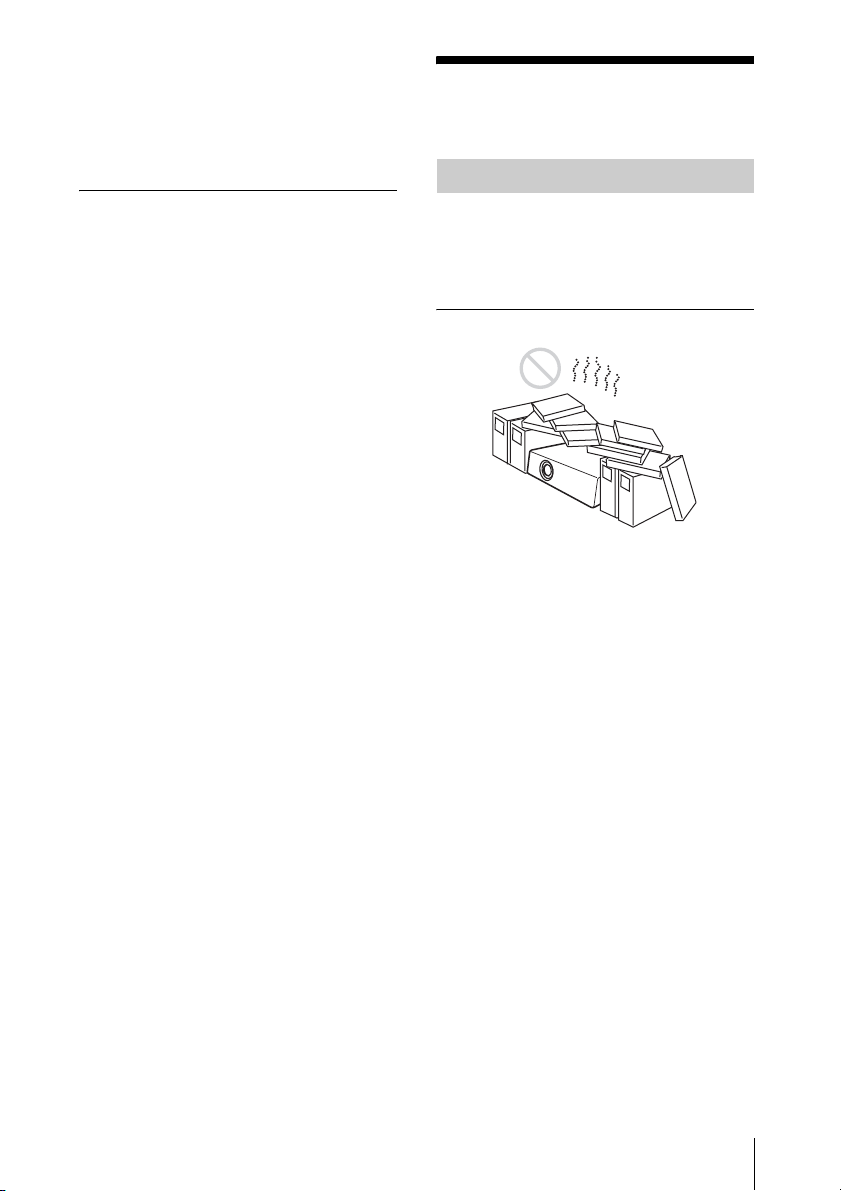
Poorly ventilated locations
• Allow adequate air circulation to prevent
internal heat build-up. Do not place the
unit on surfaces (rugs, blankets, etc.) or
near materials (curtains, draperies) that
may block the ventilation holes. When
internal heat builds up due to blockage of
ventilation holes, the temperature sensor
will function, and the power will be turned
off automatically.
• Leave space of more than 30 cm (11
inches) around the unit.
• Be careful not to allow the ventilation
holes to inhale tiny objects such as pieces
of paper or clumps of dust.
7
/8
Notes on Installation and Usage
7
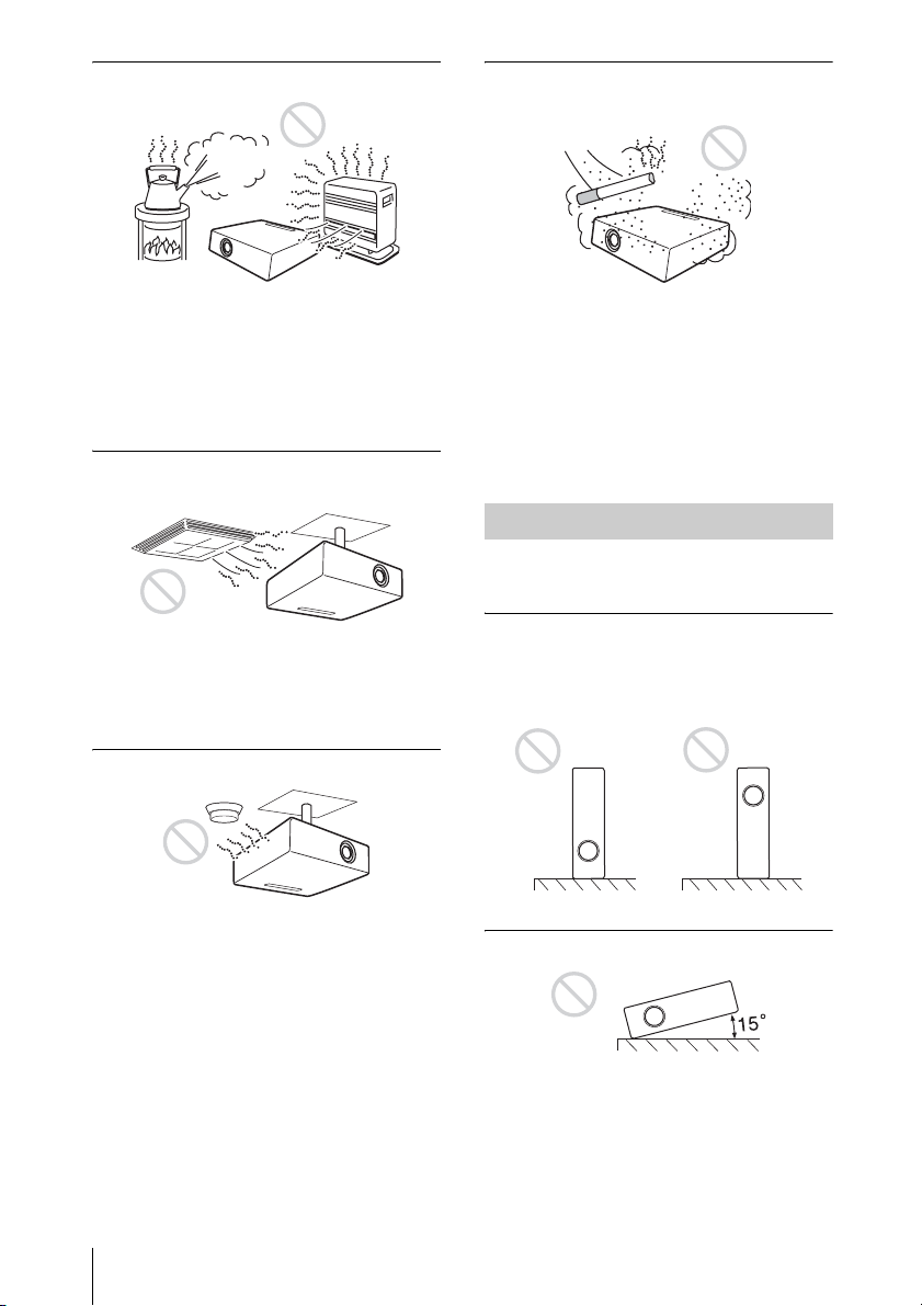
Hot and humid
Very dusty, extremely smoky
locations
• Avoid installing the unit in a location
where the temperature or humidity is very
high, or the temperature is very low.
• To avoid moisture condensation, do not
install the unit in a location where the
temperature may rise rapidly.
Locations subject to direct cool or
warm air from an air-conditioner
Installing the projector in such a location
may cause a malfunction of the unit due to
moisture condensation or a rise in
temperature.
Near a heat or smoke sensor
Malfunction of the sensor may occur.
Avoid installing the unit in a very dusty or
extremely smoky environment. Otherwise,
the air filter will become obstructed, and this
may cause a malfunction of the unit or
damage it. Dust preventing the air passing
through the filter may cause a rise in the
internal temperature of the unit. Clean the
air filter whenever you replace the lamp.
Unsuitable Conditions
Do not use the projector under the following
conditions.
Do not stand the unit upright on
one side
Avoid using the unit standing upright on its
side. It may cause malfunction.
Do not tilt the unit to the right or left
8
Notes on Installation and Usage
Avoid tilting the unit to an angle of 15°, and
avoid installing the unit in any way other
than placing it on a level surface or
suspending from the ceiling. Such an
installation may cause color shading or
shorten the lamp life excessively.

Do not block the ventilation holes
Usage at High Altitude
When using the projector at an altitude of
1,500 m or higher, turn on “High
Altitude Mode” in the INSTALL SETTING
menu. Failing to set this mode when using
the projector at high altitudes could have
adverse effects, such as reducing
the reliability of certain components.
Avoid using a thick-piled carpet or anything
that covers the ventilation holes (exhaust/
intake); otherwise, internal heat may build
up.
Do not place a blocking object just
in front of the lens
Do not place any object just in front of the
lens that may block the light during
projection. Heat from the light may damage
the object. Use the PIC MUTING key to cut
off the picture.
Do not use the Security bar for
transporting or installation
Notes on Use
Note on carrying the projector
The unit is manufactured using highprecision technology. When transporting the
unit, do not drop the unit or subject it to
shock, as this may cause damage.
Note on the screen
When using a screen with an uneven surface,
a striped pattern may rarely appear on the
screen depending on the distance between
the screen and the projector or the zooming
magnification settings used. This is not a
malfunction of the projector.
Use the Security bar at the rear of the
projector for a purpose of preventing theft,
by attaching a commercially available theft
prevention cable for example. If you lift the
projector by holding the Security bar, or
hang the projector by using this bar, it may
cause the projector to fall or be damaged.
Notes on Installation and Usage
9

B Overview
Features
High brightness · High picture
performance
Panel key lock
This function locks all the keys on the
control panel of the projector, allowing use
of the keys on the Remote Commander. This
prevents the projector from operating
incorrectly.
High brightness
Sony’s unique optical system allows high
efficiency.
High picture performance
Three super-high-aperture 0.63-inch
(16.0 mm) XGA panels with approximately
790,000 effective pixels produce a resolution
of 1024 × 768 dots (horizontal/vertical) for
RGB input, and 750 horizontal TV lines for
video input.
Direct Power On/Power Off function
The AC power for the entire system can be
turned on and off by means of a breaker or
other switch without going through a
standby mode.
Simple maintenance
Even when the projector is mounted on the
ceiling, you can clean the air filter easily
because it is located at the side.
Clean the filter at the same time as you
replace the lamp.
Short focal lens
The projection distance is very short,
approximately 2.4 m (7.9 feet), when
projecting an 80-inch (2,032 mm) image,
which allows projection on a larger screen
even in a limited space.
Security Functions
Other Convenient Functions
• On-screen menu in 17 languages
• Picture muting
• Freeze
• Lamp mode switching function
• Low power consumption in standby
• Security bar
Web Control
The Web Control function enables you to
operate the projector and examine its status
of the projector remotely, using a Web
browser.
About Trademarks
• Adobe Acrobat is a trademark of Adobe
Systems Incorporated.
• Windows is a registered trademark of
Microsoft Corporation in the United States
and/or other countries.
• Kensington is a registered trademark of
Kensington Technology Group.
• Macintosh is a registered trademark of
Apple Inc.
• VESA is a registered trademark of the
Video Electronics Standards Association.
• Display Data Channel is a trademark of the
Video Electronics Standards Association.
• All other trademarks and registered
trademarks are trademarks or registered
trademarks of their respective holders. In
this manual, ™ and ® marks are not
specified.
Security lock
This function makes it possible to prevent
projection of a picture on the screen unless
the required password is entered when the
projector is turned on.
10
Features
Location and Function of Controls
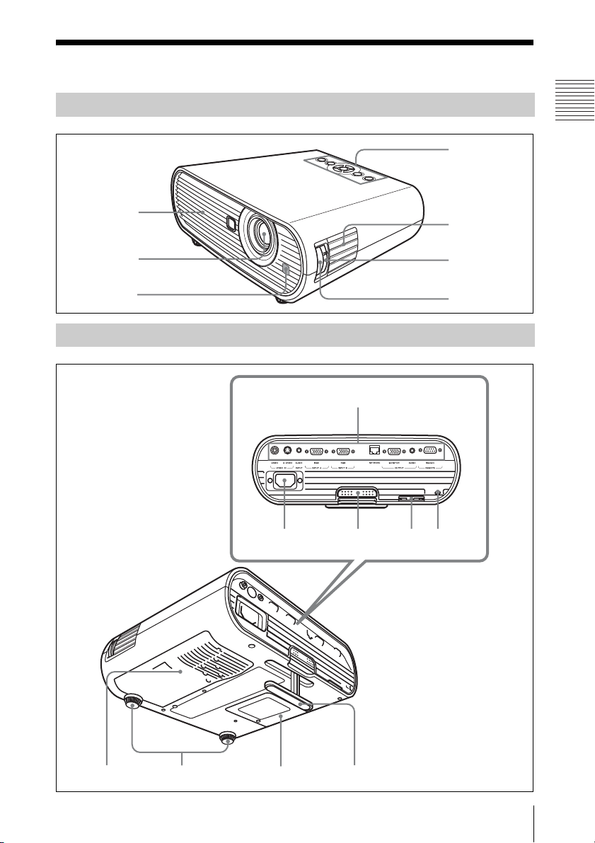
Top/Right Side/Front
Overview
4
1
2
3
Rear/Bottom
5
6
7
qs
qd qf qg qh
89 0qa
Location and Function of Controls
11
a Ventilation holes (exhaust)
b Lens
Remove the lens cover before
projection.
c Front remote control detector
d Control panel
For details, see “Control Panel” on
page 13.
Security bar
e Speaker
f Zoom ring
Adjusts the picture size.
g Focus ring
Adjusts the picture focus.
h Ventilation holes (intake)/Air
filter cover
i Adjusters (fore pad)
j Lamp cover
k Adjuster
l Connector Panel
For details, see “Connector Panel” on
page 15.
m AC IN socket
Connects the supplied AC power cord.
n Adjuster adjustment button
For details, see “Using the adjuster” on
page 21.
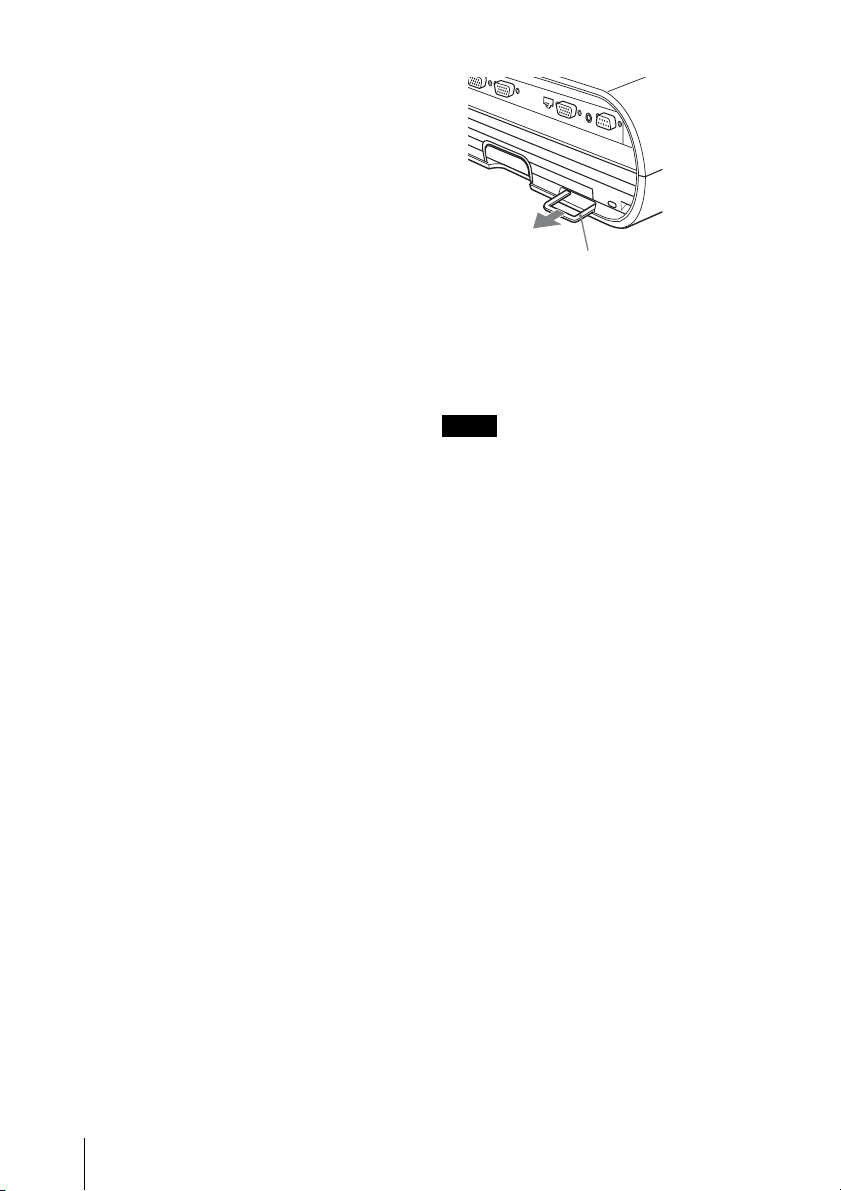
o Security bar
An anti-theft chain or wire
(commercially available) can be
connected to it.
If it is difficult to pull out, pull out the
Security bar using a screwdriver.
p Security lock
Connects to an optional security cable
(from Kensington).
Web page address:
http://www.kensington.com/
Note
To maintain optimal performance, clean the
air filter whenever you replace the lam
For details, see “Cleaning the Air Filter” on
page 48.
p.
12
Location and Function of Controls
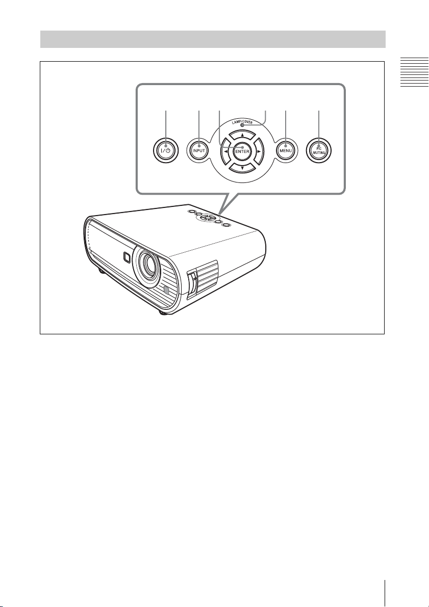
Control Panel
Overview
123 456
a ?/1 (On/Standby) key
Turns on the projector when the
projector is in standby mode. To turn off
the power, press the ?/1 key twice
according to the message or hold the ?/1
key for about one second.
Lights up or flashes under the following
conditions:
– Lights in red when the AC power cord
is plugged into a wall outlet. Once the
projector is in standby mode, you can
turn it on with the ?/1 key.
– Flashes in red when the temperature
becomes high inside the projector, or
when the projector fails to operate.
– Lights in green when the power is
turned on, and when it is ready to
operate.
– Flashes in green from the time when
the projector is turned on until the
projector is ready to operate. Also,
flashes in green while the cooling fan
is running after the power is turned off
with the ?/1 key. The fan runs for
about 90 seconds after the power is
turned off.
– Lights in orange when the power
saving mode is on.
For details, see page 22.
b INPUT key
Selects an input signal. The input signal
will change whenever you press the key.
c ENTER/v/V/b/B (Arrow) keys
Used to enter the settings of items in the
menu system, select a menu, or make
various adjustments.
d LAMP/COVER indicators
Flashes in orange under the following
conditions:
Location and Function of Controls
13

– A repetition rate of 2 flashes when the
lamp cover or air filter cover is not
secured firmly.
– A repetition rate of 3 flashes when the
lamp has reached the end of its life or
reaches a high temperature.
For details, see page 51.
e MENU key
Displays the on-screen menu. Press
again to clear the menu.
f PIC MUTING key
Cuts off the picture. Press again to
restore the picture.
14
Location and Function of Controls
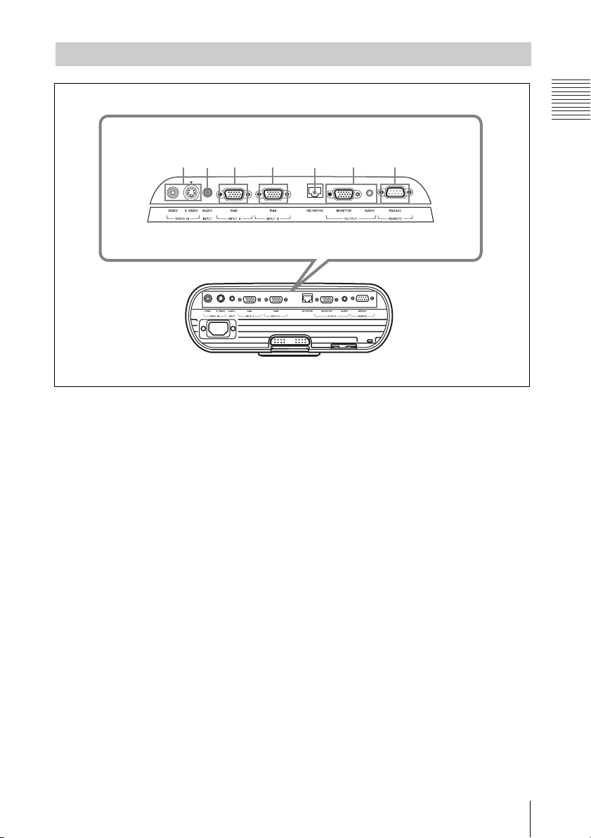
Connector Panel
13467
2 5
Overview
a VIDEO IN connector
• S VIDEO (mini DIN 4-pin):
Connects to the S video output of
video equipment.
• VIDEO (phono type):
Connects to the video output of video
equipment.
b AUDIO INPUT connector
Inputs audio signal attached to the image
from INPUT A, INPUT B or VIDEO.
c INPUT A connector
RGB (HD D-sub 15-pin, female):
Inputs a computer signal, video GBR
signal, component signal, or DTV signal
depending on the connected equipment.
Connects to the output connector of
equipment using the supplied cable or an
optional cable.
For details, see “Connecting a
Computer” on page 18 and
“Connecting a VCR” on page 19.
d INPUT B connector
RGB connector (HD D-sub 15-pin,
female):
Inputs a computer signal.
Connects to the output connector of
equipment using the supplied cable or an
optional cable.
e NETWORK connector (RJ-45)
Connects to a computer connector
through which to operate the projector
via a network.
CAUTION
For safety, do not connect the connector
for peripheral device wiring that might
have excessive voltage to this port.
Follow the instructions for this port.
f OUTPUT connector
• MONITOR (HD D-sub 15-pin
female):
Connects to the input connector of the
monitor. Only the computer signal on
the current channel is output from
among the signals connected to
INPUT A or INPUT B.
• AUDIO (stereo minijack):
Connects to the active speaker. Adjust
the volume with VOLUME +/– on the
remote commander.
Location and Function of Controls
15
When VIDEO, S VIDEO or INPUT A
9
is selected, the output audio is the
signal input to AUDIO INPUT.
g REMOTE RS-232C connector (D-
sub 9-pin female)
Connects to the connector of the
computer when you operate the
projector from the computer.
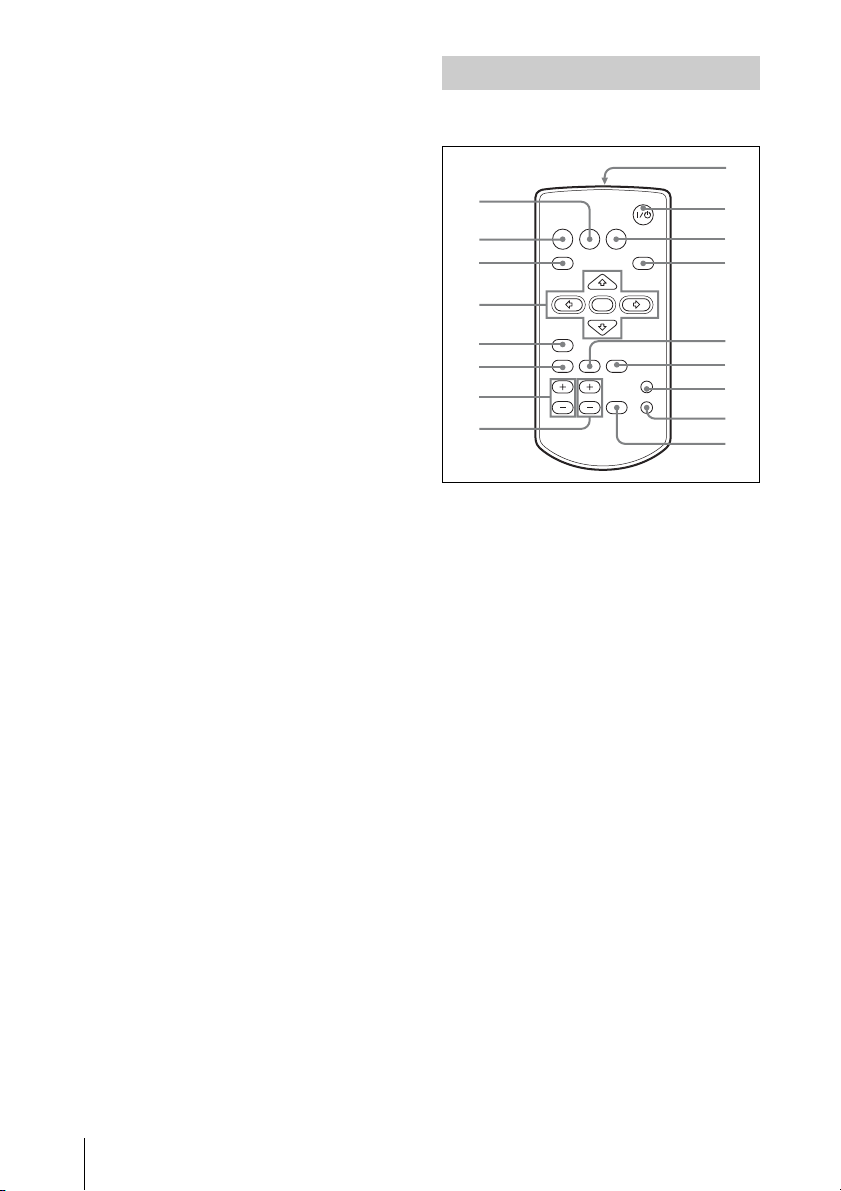
Remote Commander
The keys that have the same names as those
on the control panel function identically.
1
2
3
INPUT
MENU
NETWORK USB
APA
0
qa
qs
RESET
AUTO FOCUS
D ZOOM
LENS
VOLUME
ENTER
KEYSTONE
/TILT
FREEZE
PIC MUTING
AUDIO MUTING
4
5
6
7
8
a NETWORK key
This function is not provided in this
projector.
b INPUT key
c MENU key
d ENTER/v/V/b/B (Arrow) keys
e RESET key
Resets the value of an item to its factory
preset value or returns the enlarged
image with D ZOOM key to its original
size. This key functions when the menu
or a setting item is displayed on the
screen.
f AUTO FOCUS key
This function is not provided in this
projector.
qd
qf
qg
qh
qj
16
Location and Function of Controls
g D ZOOM (Digital Zoom) +/– key
Enlarges the image at a desired location
on the screen. (Digital Zoom function)
h VOLUME +/– key
i Infrared transmitter
j ?/1 (On/Standby) key
k USB key
This function is not provided in this
projector.
l APA (Auto Pixel Alignment) key
Automatically adjusts a picture to its
clearest while a signal is input from a
computer.
For details, see “Smart APA” in “The
SET SETTING Menu” on page 34.
Overview
m LENS key
This function is not provided in this
projector.
n KEYSTONE (Trapezoidal
distortion correction) /TILT key
Adjusts the vertical trapezoidal
distortion of the image. Pressing this
key, the adjustment menu are displayed.
Use the arrow keys (v/V/b/B) for
adjustment.
o PIC MUTING key
Cuts off the picture. Press again to
restore the picture.
p AUDIO MUTING key
Cuts off the sound. Press again to restore
the sound.
q FREEZE key
Freezes the projected picture. To cancel
the frozen picture, press the key again.
This function is available when the PC
signal is input.
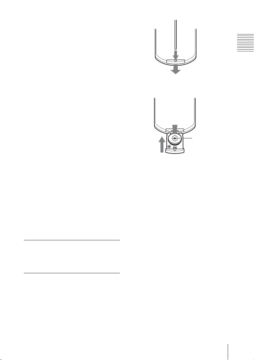
Before using the Remote
Commander
Pull out the clear film from the lithium
battery holder.
To replace a battery
1 Pull out the battery cover by a thin
stick inserting to a hole, as shown the
illustration.
2 Install the lithium battery.
Face th e +
side up.
3 Put the lithium battery holder back
into the Remote Commander.
Notes on the lithium battery
• A button type lithium battery (CR2025) is
used in the Remote Commander. Do not
use batteries other than CR2025.
• Keep the lithium battery out of the reach of
children.
• Should the battery be swallowed,
immediately consult a doctor.
Notes on Remote Commander
operation
• Make sure that nothing obstructs the
infrared beam between the Remote
Commander and the remote control
detector on the projector. Aim the Remote
Commander at the front of the remote
control detector or the screen.
• The operation range is limited. The shorter
the distance between the Remote
Commander and the remote control
detector is, the wider the angle within
which the commander can control the
projector becomes.
Location and Function of Controls
17

B Projecting the Picture
Installing the Projector
This unit can be operated on a floor or
desktop (floor installation), but also can be
suspended from a ceiling with a dedicated
mounting device (ceiling installation).
For details, see “Installation Diagram” on
page 58.
Connecting the Projector
When you connect the projector,
make sure to:
• Turn off all equipment before making any
connections.
• Use the proper cables for each connection.
• Insert the cable plugs firmly; loose
connections may increase noise and
reduce performance of picture signals.
When pulling out a cable, be sure to pull it
out by the plug, not the cable itself.
Connecting a Computer
This section describes how to connect the
projector to a computer.
For more information, refer to the
computer’s instruction manual.
18
Installing the Projector / Connecting the Projector

To connect a computer
Rear side
For details, refer to the operating
instructions supplied with your computer.
Note
To connect a Macintosh computer equipped
with a video output connector of a type having
two rows of pins, use a commercially available
plug adaptor.
to monitor output
Computer
to audio input
1 HD D-sub 15-pin cable (supplied)
2 Stereo audio connecting cable (not supplied)
(Use a no-resistance cable.)
Notes
• For stereo audio connection, connect the
stereo audio connecting cable to the AUDIO
INPUT connector.
• The projector accepts VGA, SVGA, XGA,
SXGA, SXGA+, WXGA signals. However,
we recommend that you set the output mode
of your computer to XGA mode for the
external monitor.
• If you set your computer, such as a notebook
computer, to output the signal to both your
computer’s display and the external monitor,
the picture of the external monitor may not
appear properly. Set your computer to output
the signal to only the external monitor.
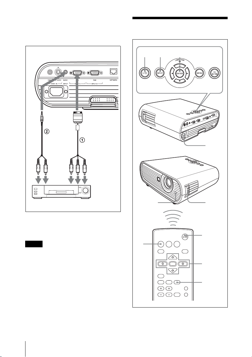
Connecting a VCR
This section describes how to connect the
projector to a VCR.
For more information, refer to the
instruction manuals of the equipment you
are connecting.
To connect to a video or S video
output connector
Rear side
to audio
output (L)
to video
output
1 Stereo audio connecting cable (not supplied)
(Use a no-resistance cable.)
to S
video
output
VCR
Projecting the Picture
to audio
output (R)
Connecting the Projector
19
2 Video cable (not supplied) or S-Video cable
(not supplied)
To connect to a video GBR/
Component output connector
Projecting
Rear side
to audio
to audio
output (R)
output
(L)
to video GBR/
component
output
VCR
1 Signal Cable (not supplied)
HD D-sub 15-pin (male) ↔ 3 × phono plugs
2 Stereo audio connecting cable (not supplied)
(Use a no-resistance cable.)
Notes
• For stereo audio connection, connect the
stereo audio connecting cable to the AUDIO
INPUT connector.
• Set the aspect ratio using “Aspect” on the
INPUT SETTING menu according to the
input signal.
• When you connect the projector to a video
GBR output connector, select “Video GBR”
or when you connect the projector to a
component output connector, select
“Component” with the “Input-A Signal Sel.”
setting on the SET SETTING menu.
41,2 7
Front
remote
control
detector
INPUT
NETWORK USB
4
1 Plug the AC power cord into a wall
MENU
RESET
AUTO FOCUS
D ZOOM
LENS
VOLUME
ENTER
KEYSTONE
/TILT
FREEZE
APA
PIC MUTING
AUDIO MUTING
outlet, and connect all equipment, then
remove the lens cover.
1
8
2
7
7
20
Projecting
 Loading...