

Sony VPL-SX630, VPL-SW620C, VPL-SW630C, VPL-SW630, VPL-SW620 User Manual
...
Data
Projector
4-532-769-14 (1)
Operating Instructions
Before operating the unit, please read this manual and supplied Quick Reference Manual
thoroughly and retain it for future reference.
VPL-SW635C/SW630C/SW620C/SW630/SW620
VPL-SX630
Not all models are available in all countries and area. Please check
with your local Sony Authorized Dealer.
© 2014 Sony Corporation

Table of Contents
Overview
Location and Function of Controls ....4
Main Unit .....................................4
Terminals ......................................5
Remote Commander and Control
Panel Keys .................................6
Interactive Pen Device (VPL-
SW635C/SW630C/SW620C
only) ..........................................8
Preparation
Connecting the Projector ................... 9
Connecting a Computer ................9
Connecting a Video
equipment ................................ 11
Connecting a microphone .......... 13
Connecting a USB memory
device ......................................13
Connecting an External Monitor and
Audio Equipment .................... 13
Projecting/Adjusting an
Image
Projecting an Image .........................14
Adjusting the Projected image ... 16
Turning Off the Power ................19
The Operation Menu ........................28
The Connection/Power Menu ...........29
The Installation Menu ......................31
The Information Menu .....................32
Notes When Using PC Free Interactive
Function (VPL-SW635C only) .....33
Network
Using Network Features ...................34
Displaying the Control Window of
the Projector with a Web
Browser ...................................34
Confirming the Information
regarding the Projector ............35
Operating the Projector from a
Computer .................................36
Using the e-mail report
Function ...................................36
Setting the LAN Network of the
projector ..................................37
Setting the WLAN Network of the
projector ..................................38
Setting the Custom Labels for the
Input Terminals of the
Projector ..................................40
Setting the Control Protocol of the
Projector ..................................40
Interactive Function
Adjustments and Settings
Using a Menu
Using a MENU ................................20
The Picture Menu .............................21
The Screen Menu .............................22
The Function Menu .......................... 26
2
Table of Contents
Using Interactive Presentation Utility 2
(VPL-SW635C/SW630C/SW620C
only) ..............................................44
Connecting a Computer with a USB
Cable ........................................45
For Windows ...............................45
For Mac .......................................48

Using the PC Free Interactive Function
(VPL-SW635C only) ....................50
Setting the PC Free Interactive
Function ..................................50
Retrieve the Data Saved in the
Projector ..................................55
Using the Mouse Mode Function
(VPL-SW635C only) ....................56
Setting the Mouse Mode .............56
Operations of Interactive Pen
Device While Using Mouse
Mode .......................................57
Presentation Function via
Network
Using Presentation Function via
Network ........................................58
Installing Projector Station for
Network Presentation ..............58
Starting Projector Station for
Network Presentation ..............58
Projecting an Image ....................59
Connection Settings ....................60
Using the Controller ...................60
Displaying Images or Files Sent
from a Tablet
PC/Smartphone .......................61
USB Media Viewer
Using USB Media Viewer ............... 64
Thumbnail Mode ........................ 65
Option Menu .............................. 65
Display Mode ............................. 66
Option Menu .............................. 66
Slideshow Mode ......................... 66
Option Menu .............................. 67
Others
Indicators ......................................... 68
Messages List .................................. 69
Troubleshooting ............................... 70
Replacing the Lamp ......................... 74
Cleaning the Air Filter ..................... 76
Specifications ................................... 78
Projection Distance and Lens Shift
Range ............................................ 85
Dimensions ...................................... 89
END USER LICENSE
AGREEMENT ............................. 91
Index ................................................ 97
Playing Video and Audio
using USB Connection
Playing Video and Audio using USB
Connection ....................................62
Starting USB Display .................62
Playing Video and Audio ...........62
Using the Controller ...................62
Table of Contents
3
B Overview
Location and Function of Controls
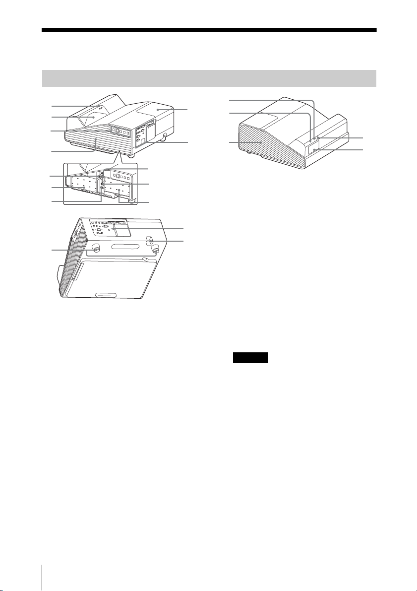
Main Unit
1
2
3
4
5
6
7
9
8
6
qs
a Interactive Pen detector
(VPL-SW635C/SW630C/SW620C
only)
b Projection window
c Control panel keys (page 6)
d Side cover/Ventilation hole
(intake)
e Focus lever (page 16)
f Air filter (page 76)
g Lens shift dial H (page 17)
qf
qd
qa
0
qg
qh
qj
m Security bar
Connects to a commercially available
security chain or wire.
n Security lock
Connects to an optional security cable
manufactured by Kensington.
For details, visit Kensington’s web site.
http://www.kensington.com/
o ON/STANDBY indicator
(page 68)
p LAMP/COVER indicator
(page 68)
q Ventilation holes (exhaust)
Caution
Do not place anything near the ventilation
holes as this may cause internal heat
buildup. Do not place your hand near the
ventilation holes and the circumference as
this may cause injury.
r Speaker
s Remote control receiver
ql
qk
h Lends shift dial V (page 17)
i Zoom lever (page 16)
j Terminals (page 5)
k Lamp cover (page 74)
l Foot (page 17)
4
Location and Function of Controls
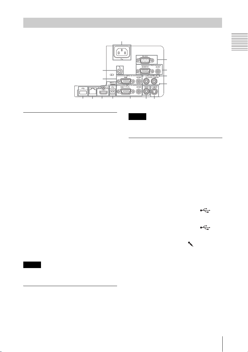
Terminals
9
Overview
7
qs
2
3
qa
8q;
Input (pages 9, 11)
a INPUT A
Video: RGB/YPBPR input terminal
(RGB/YPBPR)
Audio: Audio input terminal (AUDIO)
b INPUT B
Video: RGB input terminal (RGB)
Audio: Audio input terminal (AUDIO)
c INPUT C
Video: HDMI input terminal (HDMI)
Audio: HDMI input terminal (HDMI)
d S VIDEO (S VIDEO IN)
Video: S video input terminal
(S VIDEO IN)
Audio: Audio input terminal
(L (MONO) AUDIO/R)
e VIDEO (VIDEO IN)
Video: Video input terminal (VIDEO)
Audio: Audio input terminal
(L (MONO) AUDIO/R)
Note
The audio inputs of S VIDEO and VIDEO are
shared.
6
4
5
1
Note
This terminal outputs the projected image only
when INPUT A or INPUT B is used.
Others
g RS-232C terminal (RS-232C)
h LAN terminal (page 34)
i AC IN (∼) socket
j USB terminal (Type A) ( )
k USB terminal (Type B) ( )
l Microphone input ( )
4
5
RS-232C compatible control terminal.
Connects the computer’s RS-232C
terminal and the RS-232C cross cables.
Connects the supplied AC power cord.
(pages 13, 64)
(page 62)
Output (page 13)
f OUTPUT
Video: Monitor output terminal
(MONITOR)
Audio: Audio output terminal (AUDIO)
Location and Function of Controls
5
Remote Commander and Control Panel Keys
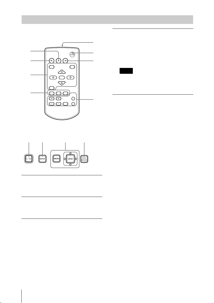
Remote Commander
7
4
INPUT
APA ECO MODE
2
3
4
Control Panel Keys
12
a Turning on the power/Going to
standby mode
?/1 (On/Standby) key
b Selecting an input signal
(page 14)
INPUT key
c Operating a menu (page 20)
MENU key
RESET key
ENTER /V/v/B/b (arrow) keys
RETURN key
MENU
RETURN
ASPECT
D ZOOM
KEYSTONE
VOLUME
ENTER
PATTERN
FREEZE
3
RESET
BLANK
MUTING
1
6
5
6
d Adjusting the image (page 16)
ASPECT key (page 22)
KEYSTONE key (page 18)
PATTERN key (page 18)
APA (Auto Pixel Alignment) key
*
(page 18)
Note
*1: Use this key when inputting a
computer signal via the RGB input
terminal (INPUT A or INPUT B).
e Using various functions during
projecting
D ZOOM (Digital Zoom) +/– key
*1 *
Enlarges a portion of the image while
projecting.
1 Press the D ZOOM + key to display
the digital zoom icon on the projected
image.
2 Press the V/v/B/b keys to move the
digital zoom icon to the point on the
image you want to enlarge.
3 Press the D ZOOM + key or the D
ZOOM – key repeatedly to change the
enlargement ratio. The image can be
enlarged up to 4 times.
Press the RESET key to restore the
previous image.
BLANK key
Cuts off the projected image
temporarily. Press again to restore the
previous image. Picture muting helps
reduce power consumption.
MUTING key
Mutes the audio output temporarily.
Press again to restore the previous
volume.
VOLUME +/– key
Adjusts the volume output.
FREEZE key
*2 *3
Pauses a projected image. Press again to
restore the image.
1
3
6
Location and Function of Controls
Notes
*1: Use this key when inputting a
computer signal. But it may not be
used depending on the resolution of
the input signal.
*2: Use this key when inputting a
computer signal.You cannot use this
key when
“Type A USB”, “Type B
USB” or “Network” is selected as the
input.
*3: This does not work for data drawn with
the Interactive Pen Device using the
PC Free Interactive function. This
works only for background images
from an external device. (VPLSW635C only)
f Setting the energy–saving mode
easily
ECO MODE key
Energy-saving mode can be set easily.
Energy-saving mode consists of “Lamp
Mode,” “With No Input,” “With Static
Signal” and “Standby Mode.”
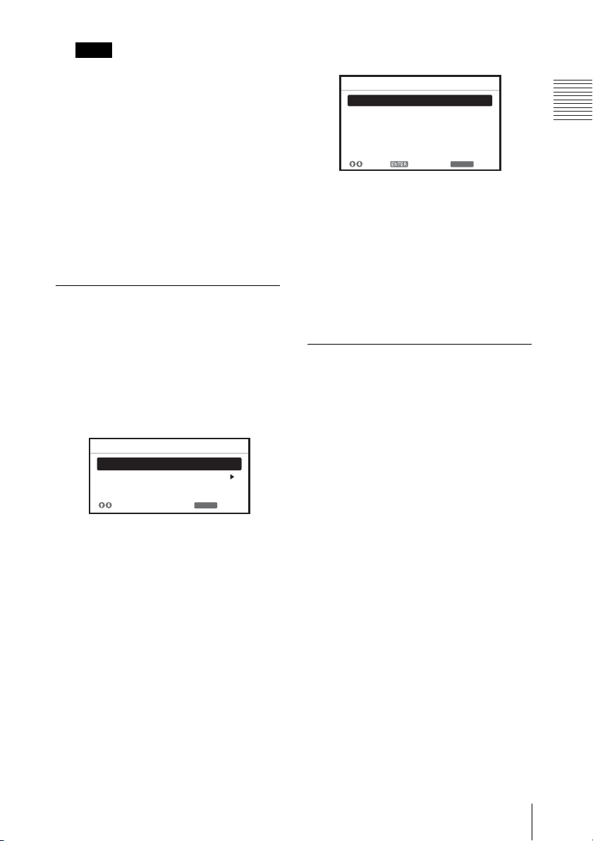
1 Press the ECO MODE key to display
the ECO Mode menu.
ECO Mode
ECO
User
RETURN
:Sel
:Back
2 Press the V/v key or ECO MODE key
to select “ECO” or “User” mode.
ECO: Sets each mode to the optimum
energy-saving value.
Lamp Mode: Low
With No Input: Standby
With Static Signal: Lamp
Dimming
Standby Mode: Low
User: Sets each item of the ECO
Mode menu as you desire (go to
step 3).
3 Select “User” then press the b key.
The setting items appear.
User
Lamp Mode High
Constant Brightness
Auto Power Saving
With No Input
With Static Signal
Standby Mode
:S el
:S et
ON
Off
Lamp Dimming
Standard
RETURN
:Back
4 Press the V/v key to select the item
then press the ENTER key.
5 Press the V/v key to select the setting
value.
6 Press the ENTER key.
The screen returns to the User screen.
For details on ECO Mode settings, see
“Lamp Mode,” “Constant Brightness,”
“With No Input,” “With Static Signal”
and “Standby Mode” on the Connection/
Power menu (page 29).
Others
g Infrared transmitter
About remote commander operation
• Direct the remote commander toward the
remote control receiver.
• The shorter the distance between the
remote commander and the projector is,
the wider the angle within which the
remote commander can control the
projector becomes.
• Make sure that nothing obstructs the
infrared beam between the remote
commander and the remote control
receiver on the projector.
Overview
Location and Function of Controls
7

Interactive Pen Device (VPL-SW635C/SW630C/SW620C only)
5
12 34 6
a Pen tip switch
Functions as the left button of a mouse.
b Color ring
main (IFU-PN250A): red
sub(IFU-PN250B): blue
c Indicator
This indicator flashes when the button is
pressed and lights up when the pen tip
touches the screen. It will not light up if
battery power is low. In this case, replace
the batteries.
d Button
Main: Switches between drawing and
mouse functions.When using mouse
mode, you can use this button as a rightclick (page 57).
Sub: Displays the sub pen toolbar.
e Battery cover
The battery cover is attached to the
Interactive Pen Device by a small strap.
Be careful not to break the strap when
opening the battery cover.
f Strap attachment hole
8
Location and Function of Controls
B Preparation
Connecting the Projector
Notes
• Make sure all the equipment is powered off when connecting the projector.
• Use the proper cables for each connection.
• Insert the cable plugs firmly; Loose connections may reduce performance of picture signals or
cause a malfunction. When pulling out a cable, be sure to grip it by the plug, not the cable itself.
• For more information, refer also to the instruction manuals of the equipment you are connecting.
• Use a no-resistance audio cable.
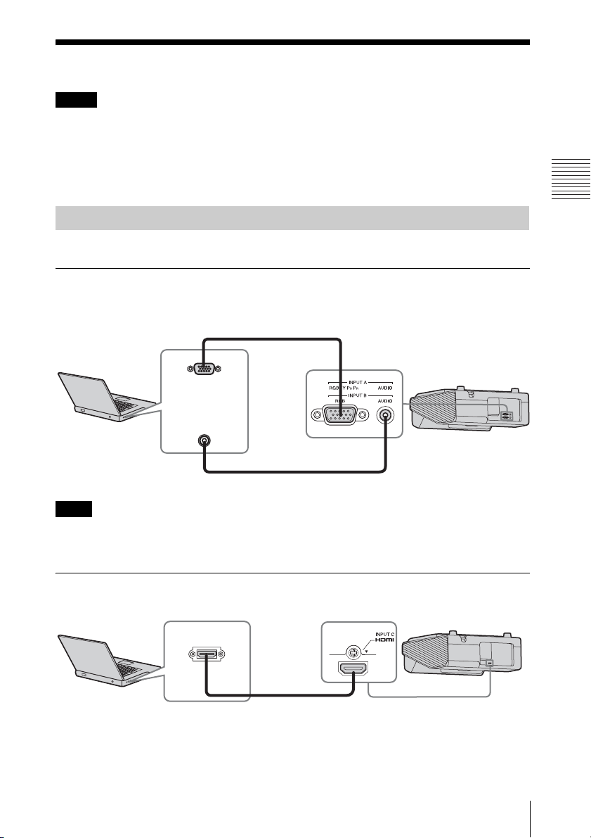
Connecting a Computer
Connection with a computer is explained for each input signal.
INPUT A/INPUT B
For connecting a computer with an RGB output terminal.
Mini D-sub 15-pin cable (not supplied)
RGB output
terminal
Audio output
Computer
terminal
Preparation
Audio cable (Stereo mini plug) (not supplied)
Note
It is recommended that you set the resolution of your computer to 1280 × 800 pixels
(VPL-SW635C/SW630C/SW620C/SW630/SW620) or 1024 × 768 pixels (VPL-SX630) for
the external monitor.
INPUT C
For connecting a computer with an HDMI output terminal.
HDMI output
terminal
Computer
HDMI cable
(not supplied)
Connecting the Projector
9
Notes
• Use HDMI-compatible equipment which has the HDMI Logo.
• Use a high speed HDMI cable(s) on which the cable type logo is specified. (Sony products are
recommended.)
• The HDMI terminal of this projector is not compatible with DSD (Direct Stream Digital) Signal
or CEC (Consumer Electronics Control) Signal.
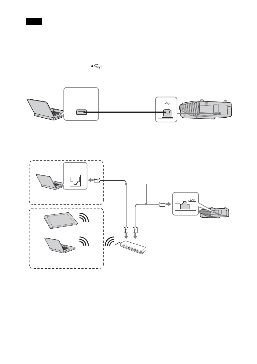
USB terminal (Type B) ( )
For connecting to a computer with a USB terminal (“Playing Video and Audio using USB
Connection” (page 62)).
USB terminal
(Type A)
Computer
USB A-B cable (not
supplied)
LAN terminal
For connecting to a computer, tablet PC, or smartphone via a hub or router (“Presentation
Function via Network” (page 58)).
LAN
terminal
LAN cable (straight type)
Computer
Wired connection
(not supplied)
Tablet PC/Smartphone
10
Connecting the Projector
Computer
Wireless connection
Hub, Wireless router, etc.
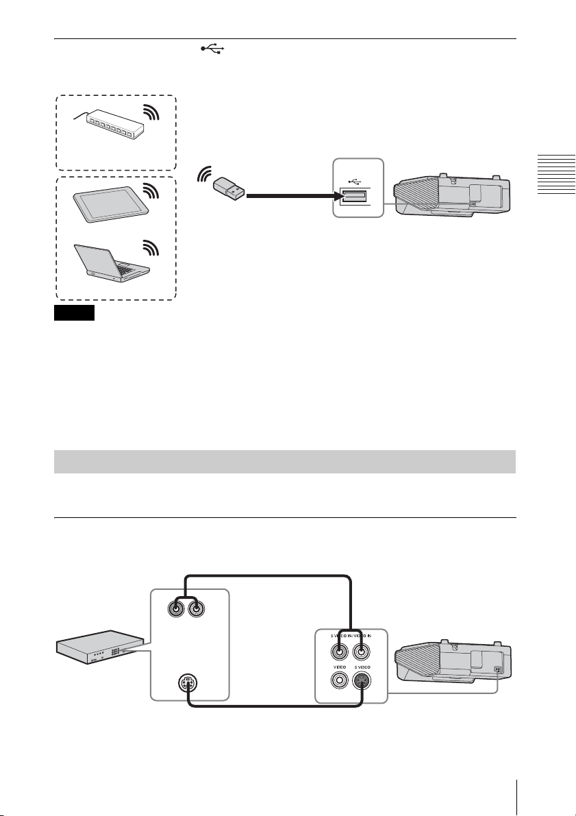
USB terminal (Type A) ( )
For connecting a USB wireless LAN module IFU-WLM3 (not supplied) (“Presentation
Function via Network” (page 58)).
Wireless router, access
point
USB wireless LAN module
Tablet PC/Smartphone
Computer
Notes
IFU-WLM3 (not supplied)
• Undesignated USB wireless LAN modules do not work.
• When connecting/disconnecting the USB wireless LAN module, make sure that the projector is in
Standby mode (Standby Mode: “Low”), or the AC power cord is unplugged from the wall outlet.
• When wirelessly connecting a tablet PC/smartphone to the projector via USB wireless LAN
module IFU-WLM3 (not supplied), set “WLAN Network” to “Access Pt. (Manual)” in the
projector’s “WLAN Settings” (page 29).
• For connecting to the access point, access to the Web browser, and input the settings for the access
point to connect. For details, see “Setting the WLAN Network of the projector” (page 38).
Preparation
Connecting a Video equipment
Connections with a VHS video deck, DVD player, or BD player are explained for each input
signal.
S VIDEO IN
For connecting video equipment with an S-video output terminal.
Audio cable (Phono plug × 2) (not supplied)
Audio output
Video equipment
terminal
S video output
terminal
S video cable (not supplied)
R-AUDIO-L(MONO)
Connecting the Projector
11
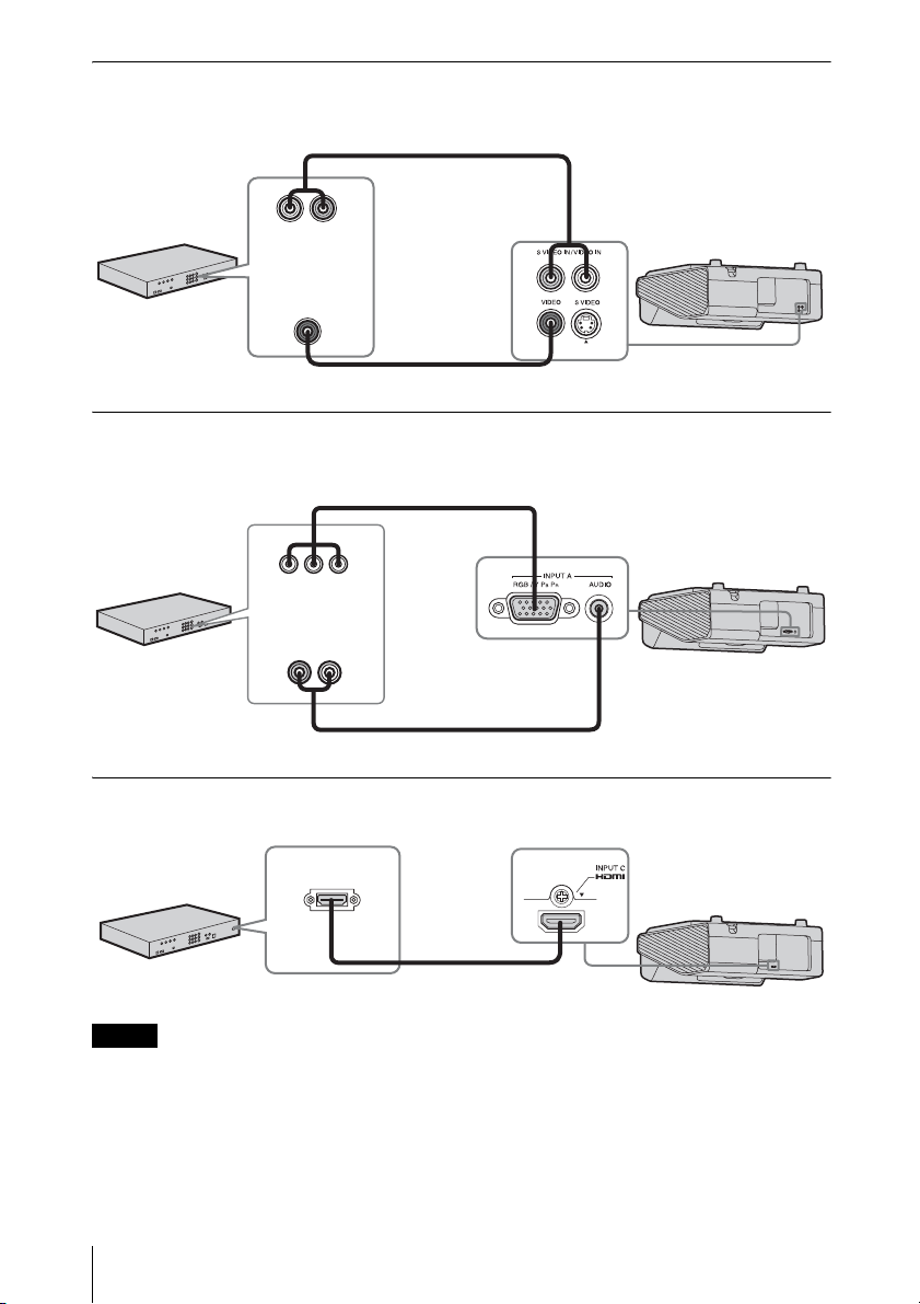
VIDEO IN
For connecting video equipment with a video output terminal.
Audio cable (Phono plug × 2) (not supplied)
Audio output
Video equipment
terminal
Video output
terminal
Video cable (not supplied)
R-AUDIO-L(MONO)
INPUT A
For connecting video equipment with a YPBPR output terminal.
Component – Mini D-sub 15-pin cable (not supplied)
BPR output
YP
terminal
Audio output
Video equipment
terminal
Audio cable (Phono plug × 2 – stereo mini plug) (not supplied)
INPUT C
For connecting video equipment with an HDMI output terminal.
HDMI output
terminal
Video equipment
HDMI cable
(not supplied)
Notes
• Use HDMI-compatible equipment which has the HDMI Logo.
• Use a high speed HDMI cable(s) on which the cable type logo is specified. (Sony products are
recommended.)
• The HDMI terminal of this projector is not compatible with DSD (Direct Stream Digital) Signal
or CEC (Consumer Electronics Control) Signal.
12
Connecting the Projector
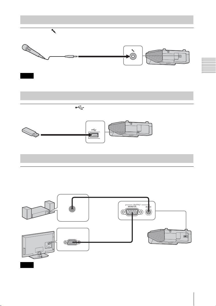
Connecting a microphone
Microphone ( )
For connecting a microphone.
Microphone
(not supplied)
Note
Only dynamic microphones are supported.
Connecting a USB memory device
USB terminal (Type A) ( )
For connecting a USB memory device (“Using USB Media Viewer” (page 64)).
USB memory device
(not supplied)
Connecting an External Monitor and Audio Equipment
Preparation
OUTPUT
Projected images or input audio can be output to display equipment such as a monitor or audio
equipment such as speakers with a built-in amplifier.
Audio cable (stereo mini
Audio equipment
Audio input
terminal
Display equipment
RGB input
terminal
Note
plug) (not supplied)
Mini D-sub 15-pin cable
(not supplied)
Projected images and audio can be output.
Connecting the Projector
13
B Projecting/Adjusting an Image
Projecting an Image
The size of a projected image depends on the distance between the projector and screen. Install
the projector so that the projected image fits the screen size. For details on projection distances
and projected image sizes, see
Notes
• Due to the characteristics of ultra short throw projector, the image may appear uneven on a
projection surface that is not absolutely flat. This is not a malfunction of the projector.
• Project the image on a flat surface.
“Projection Distance and Lens Shift Range” (page 85).
4
Video equipment
6
Computer
2
Projector
1 Plug the AC power cord into the wall
outlet.
2 Connect all equipment to the projector
(page 9).
3 Press the ?/1 key to turn on the unit.
4 Turn on the connected equipment.
14
Projecting an Image
1
Wall outlet
5
3
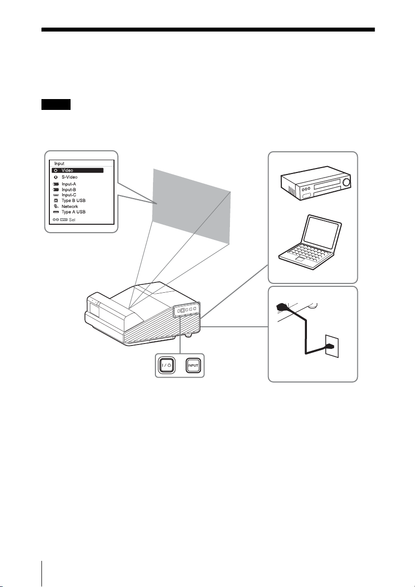
5 Select the input source.
Press the INPUT key on the projector to
display the menu for switching input
signal on the screen. Press the INPUT
key repeatedly, or press the
select an image to be projected.
V/v key to
6 When projecting a computer image,
switch your computer’s output to
external display.
The method to switch the output varies
depending on the type of computer.
(Example)
+
To project image files stored in a USB
memory device, see “USB Media
Viewer” (page 64). To play video and
audio using USB Connection, see
“Playing Video and Audio using USB
Connection” (page 62). To use
Presentation Function via Network, see
“Presentation Function via Network”
(page 58).
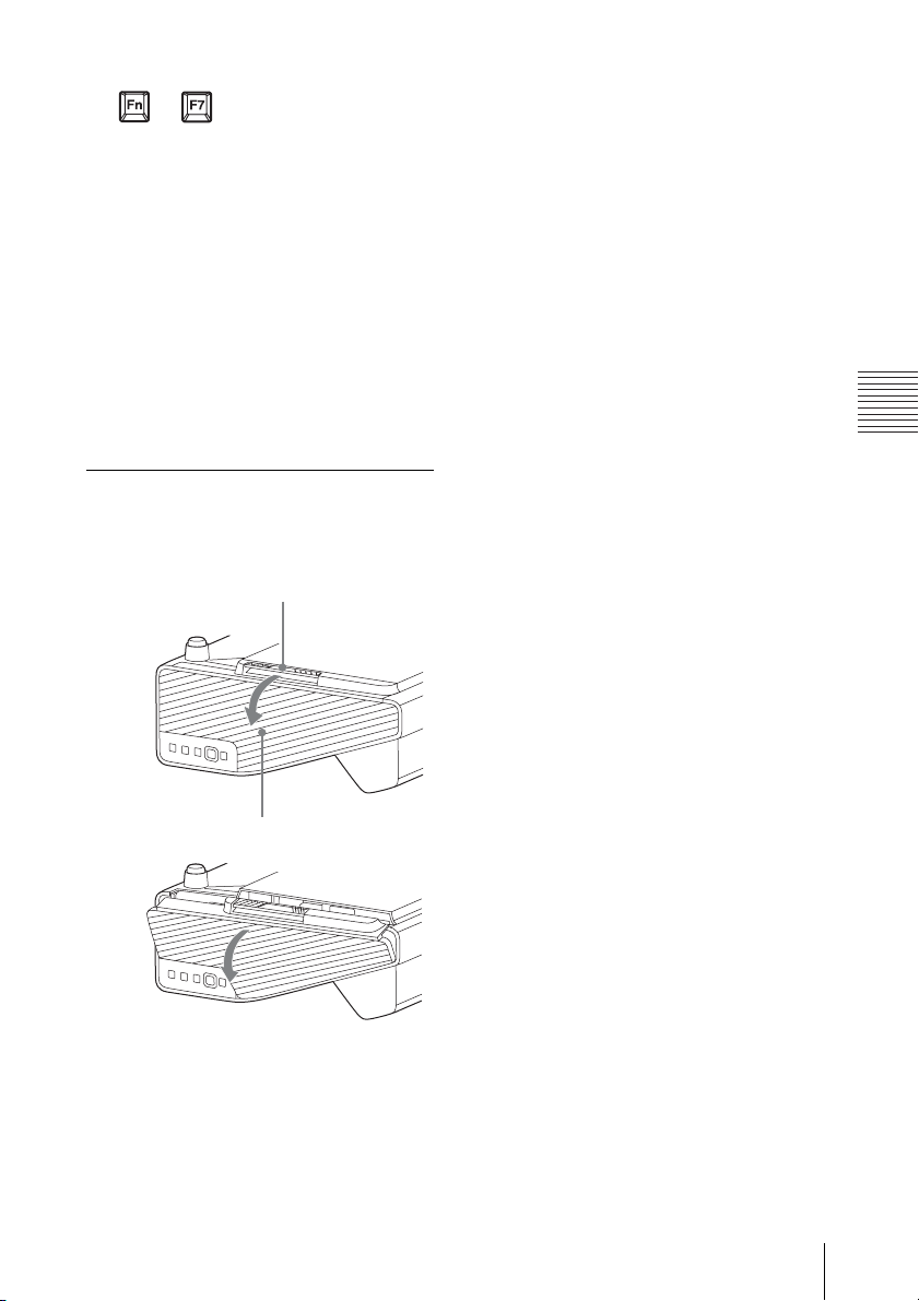
7 Adjust the focus, size and position of
the projected image (page 16).
Open the side cover, and adjust the lens
shift dials, focus lever and zoom lever.
Open the side cover
Press A and open the side cover in the
direction of the arrow shown on the
illustration below.
A
Projecting/Adjusting an Image
Side cover
Projecting an Image
15
Adjusting the Projected image
Focus Size (Zoom)
Focus
lever
Zoom
lever
16
Projecting an Image
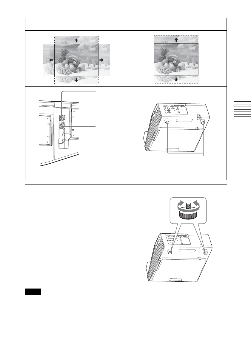
Position
(Lens shift)
Position
Lens shift
dial H
Lens shift
dial V
For adjusting lens shift, turn each dial with
your hand, screwdriver, etc.
Adjusting the tilt of the projector with the feet
You can adjust the height of the projector
using the feet.
By changing the tilt of the projector with
feet, you can adjust the position of the
projected image.
Notes
• Be careful not to let the projector down on your fingers.
• Do not push hard on the top of the projector with the foot extended.
Projecting/Adjusting an Image
Foot
Changing the aspect ratio of the projected image
Press the ASPECT key on the remote commander to change the aspect ratio of the projected
image. You can also change the setting in Aspect of the Screen menu (pages 22, 24).
Projecting an Image
17
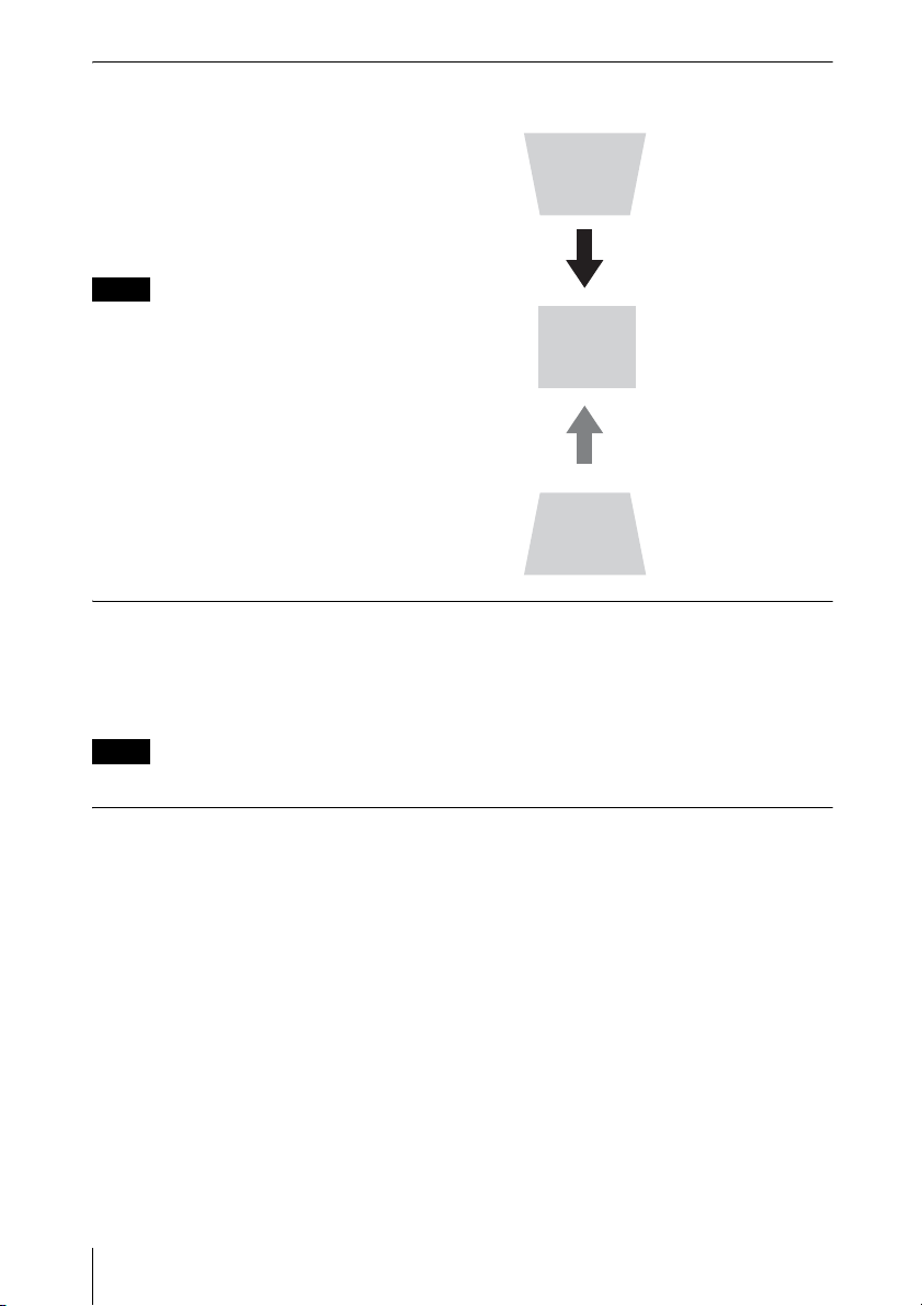
Correcting trapezoidal distortion of the projected image (Keystone feature)
If the image becomes trapezoidal, set the keystone manually.
1 Press the KEYSTONE key on the remote
commander or select V Keystone in the
Installation menu.
2 Use the V/v/B/b keys to set the value. The
higher the value, narrower the top of the
projected image. The lower the value, the
narrower the bottom.
Notes
• Since the Keystone adjustment is an
electronic correction, the image may be
deteriorated.
• Depending on the position adjusted with the
lens shift feature, the aspect ratio of the
image may change from the original or
projected image may be distorted with
Keystone adjustment.
• If you perform keystone adjustment and use
mouse mode, the position of the Interactive
Pen Device and the computer cursor may not
match. In this case, perform the calibration
again. (VPL-SW635C only)
Increase the number
towards plus
Increase the number
towards minus
Displaying a pattern
You can display a pattern for adjusting the projected image or a grid pattern with the PATTERN
key on the remote commander. Press the PATTERN key again to restore the previous image.
You can use a grid pattern as a guide to write text or to draw lines and shapes on the whiteboard
or blackboard without using a computer.
Note
You cannot use this key when “Type A USB”, “Type B USB” or “Network” is selected as the input.
Automatically adjusts Phase, Pitch and Shift of projected image while a
signal is input from a computer (APA (Auto Pixel Alignment))
Press the APA key on the remote commander. Press again to cancel adjusting during the setting.
You can also set APA in the Screen Menu (page 23). If Smart APA in the Function menu is set
to “On”, executes APA automatically when a signal is input (page 26).
18
Projecting an Image
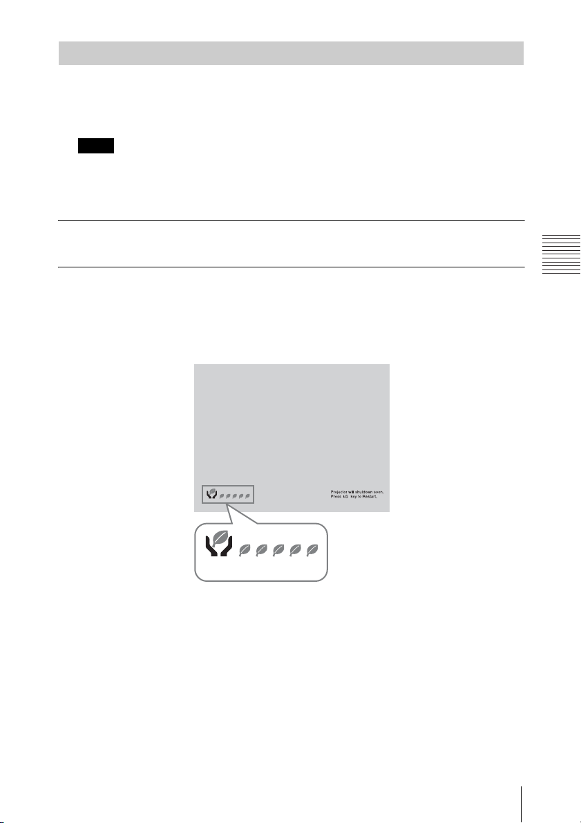
Turning Off the Power
1 Press the ?/1 key on the unit or the remote commander.
The projector starts shutdown and turns off. If you press the ?/1 key within 10 seconds
again, shutdown is cancelled.
Note
Do not turn off the projector soon after the lamp lights. It may cause a malfunction of the lamp
(does not light ,etc.).
2 Unplug the AC power cord from the wall outlet.
To turn off without displaying confirmation message
Press and hold the ?/1 key on the unit for a few seconds (page 69).
ECO gauge
This gauge indicates the current effectiveness of the projector’s ECO function. (For details on
the ECO function, see “ECO MODE key” (page 7) and “ECO” (page 29).)
The leaf icons are displayed when the projector is shut down. The number of displayed icons
varies according to how much energy is saved as a result of using the ECO function.
ECO gauge
Projecting/Adjusting an Image
Projecting an Image
19
B Adjustments and Settings Using a Menu
Using a MENU
Note
The menu displays used for the explanation below may be different depending on the model you are
using.
1 Press the MENU key to display the
menu.
2 Select the setting menu.
Use the V/v key to select the setting
menu then press the b key or ENTER
key.
Setting menu
Picture
Picture Mode Standard
Reset
Contrast
Brightness
Color
Hue
Color Temp.
Sharpness
Expert Setting
:Sel :Set :Back
Low
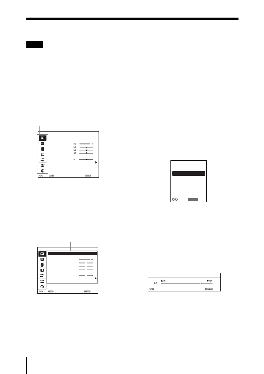
3 Select the setting item.
Use the V/v key to select the setting
menu then press the b key or ENTER
key.
To return to the selection screen of the
setting menu, press the B or RETURN
key.
Setting items
Picture
Picture Mode Standard
Reset
Contrast
Brightness
Color
Hue
Color Temp.
Sharpness
Expert Setting
80
50
50
50
Low
5
operations in step 3 and then press the
ENTER key to register the setting.
To return to the selection screen of the
setting items, press the B or RETURN
key. You can press the RESET key to
reset an item to its factory setting value
to aid setting.
Using a pop-up menu
Press the V/v/B/b key to select an item.
A selected item takes effect
immediately, except “Language”, which
will take effect after you press the
ENTER key.
Picture Mode
Dynamic
Sta ndard
Presentation
Blackbo ard
Whiteboa rd
Cinema
:Back
RETURN
:Sel
Using the setting menu
Press the V/v key to select the item.
Press the ENTER key to register the
setting and return to the previous screen.
Using the adjustment menu
To increase the value, press the V/b key
and to decrease the number, press the
v/B key. Press the ENTER key to
register the setting and return to the
previous screen.
Contrast
:Sel :Set :Back
4 Make the setting or adjustment for the
selected item.
The setting method varies, depending on
the setting item.
If the next menu window is displayed,
select the item according to the
20
Using a MENU
Adjust
Back
5 Press the MENU key to clear the
menu.
The menu disappears automatically if no
operation is performed.
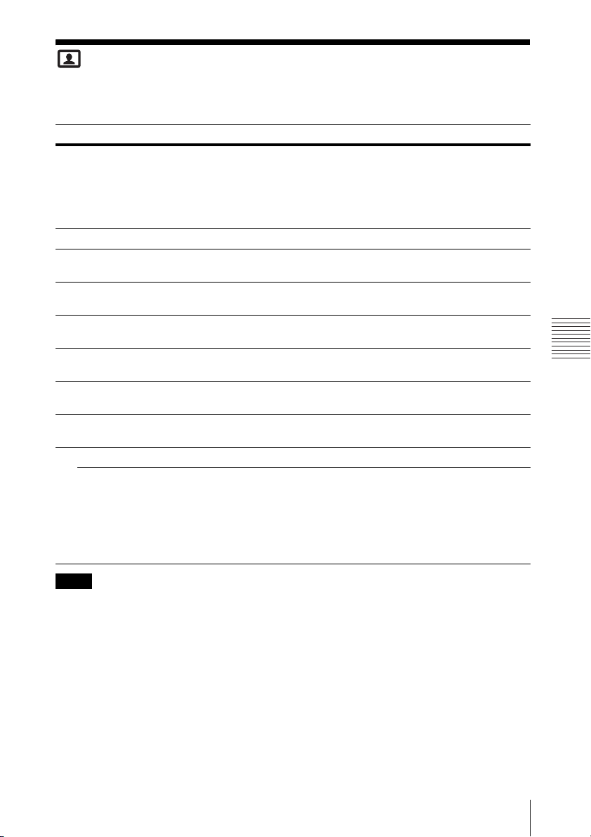
The Picture Menu
*1
The Picture is used to adjust the picture for each input signal.
Items Item descriptions
Picture Mode Dynamic: Emphasizes the contrast to produce a dynamic and vivid picture.
*3
Reset
Contrast The higher the value, the greater the contrast. The lower the value, the lower
Brightness The higher the value, the brighter the picture. The lower the value, the darker
*4 *5
Color
*4 *5 *6
Hue
Color Temp.
Sharpness
Expert Setting
*8
Gamma
*2 *9
Mode
Standard: Provides an image which is natural and well balanced.
Presentation
Blackboard: Provides an image suitable for displaying on a blackboard.
Whiteboard: Provides an image suitable for displaying on a whiteboard.
Cinema: Provides an image suitable for viewing movies.
Resets the factory setting.
the contrast.
the picture.
The higher the value, the greater the intensity. The lower the value, the lower
the intensity.
The higher the value, the more greenish the picture becomes. The lower the
value, the more reddish the picture becomes.
*7
High/Middle/Low: The higher the value, the more bluish the picture. The
lower the value, the more reddish the picture.
The higher the value, the sharper the picture. The lower the value, the softer
the picture.
Graphics1: Gamma correction to make halftones brighter. This setting is
suitable when projecting highly colorful images, such as photos, in a bright
place.
Graphics2: Gamma correction to improve the reproduction of halftones.
Highly colorful images, such as photos, can be reproduced in natural tones.
Text: Improves black and white contrast. Suitable for images with lots of text
content.
*2
: Provides a bright image, suitable for presentations.
Adjustments and Settings Using a Menu
Notes
*1: For VPL-SW635C, only “Color Temp.” is available for the data drawn with the Interactive Pen
Device using the PC Free Interactive function and in whiteboard mode. For the background
image from the external device, all the setting items work (page 33).
*2: When a computer signal is input, this option is available.
*3: The settings in the Picture return to their factory defaults, except for Picture Mode.
*4: When a video signal is input, this option is available.
*5: When the signal without color burst signal is input after selecting “Video” or “S-Video”, this
option is unavailable.
*6: When an analog TV signal is input, this option may not available, depending on the color system.
*7: When “Picture Mode” is set to the item other than “Presentation” or “Blackboard,” this option
is available.
*8: Not available if “Input” is set to “Type A USB.”
*9: When “Picture Mode” is set to “Blackboard,” this option is unavailable.
The Picture Menu
21
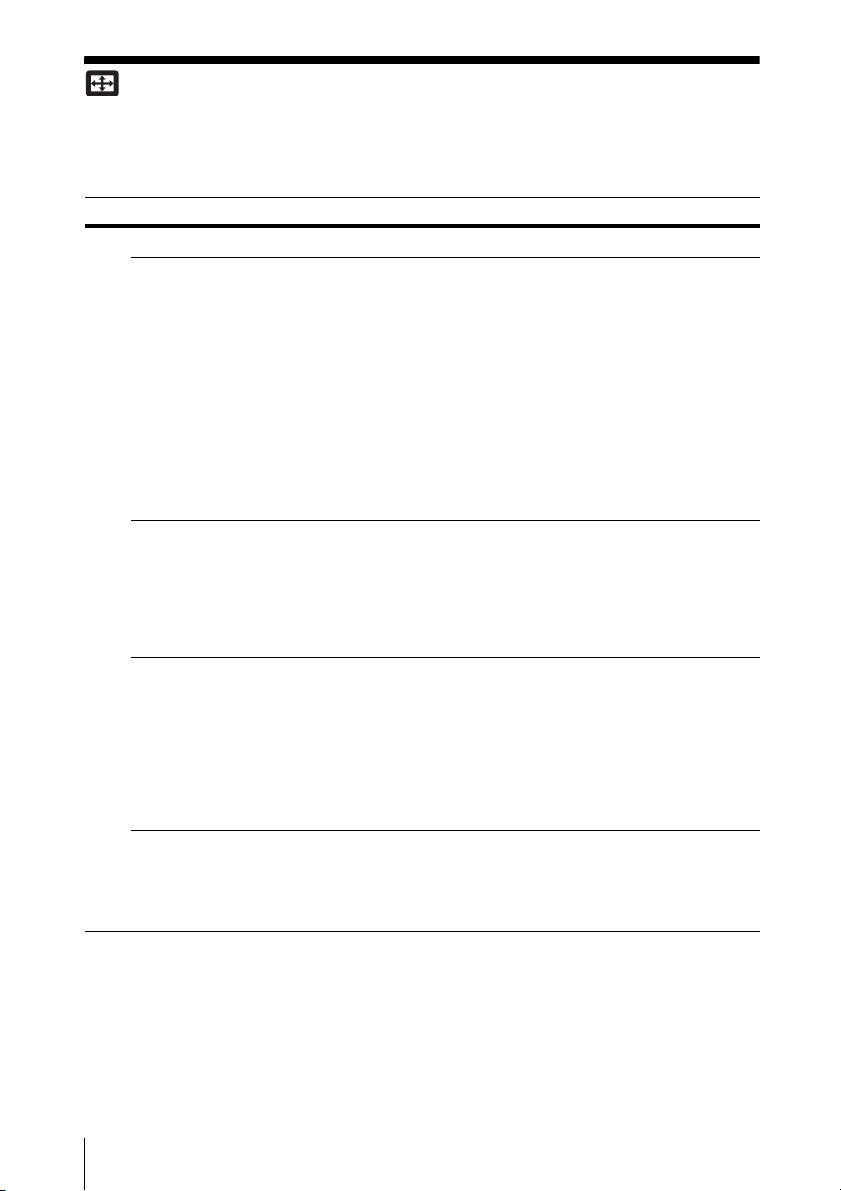
The Screen Menu
*1
The Screen menu is used to adjust the size, position and aspect ratio of the projected image for
each input signal.
Items Item descriptions
*2
Aspect
VPL-SW635C/
SW630C/SW620C/
SW630/SW620: When
the computer signal is
input
VPL-SW635C/
SW630C/SW620C/
SW630/SW620: When
the video signal is
input
VPL-SX630: When
the computer signal is
input
VPL-SX630: When
the video signal is
input
Changes the aspect ratio of the projected image (page 24).
4:3: Displays the image to fit the maximum projected image size
with an aspect ratio fixed to 4:3.
16:9: Displays the image to fit the maximum projected image size
with an aspect ratio fixed to 16:9.
Full 1: Displays the image to fit the maximum projected image
size without changing the aspect ratio of the input signal.
Full 2: Displays the image to fit the maximum projected image
size changing the aspect ratio of the input signal.
Full 3: Displays the image to fit the maximum width or height, up
to 1280 × 720 pixels, without changing the aspect ratio of the
input signal.
Normal: Displays the image on the center position of the
projected screen without changing the resolution of the input
signal or enlarging the image.
4:3: Displays the image to fit the maximum projected image size
with an aspect ratio fixed to 4:3.
16:9: Displays the image to fit the maximum projected image size
with an aspect ratio fixed to 16:9.
Full: Displays the image to fit the maximum projected image size
changing the aspect ratio of the input signal.
Zoom: Zooms the center area of a projected image.
4:3: Displays the image to fit the maximum projected image size
with an aspect ratio fixed to 4:3.
16:9: Displays the image to fit the maximum projected image size
with an aspect ratio fixed to 16:9.
Full 1: Displays the image to fit the maximum projected image
size without changing the aspect ratio of the input signal.
Normal: Displays the image on the center position of the
projected screen without changing the resolution of the input
signal or enlarging the image.
4:3: Displays the image to fit the maximum projected image size
with an aspect ratio fixed to 4:3.
16:9: Displays the image to fit the maximum projected image size
with an aspect ratio fixed to 16:9.
Zoom: Zooms the center area of a projected image.
22
The Screen Menu

Items Item descriptions
Adjust Signal Adjusts the image of computer signal. Use this item if the edge of
the image is cut and reception is bad.
APA
*3 *4
Automatically adjusts the projected image to an optimum quality
when you press the ENTER key (page 6).
*3
Phase
Adjusts the dot phase of the display pixel and the input signal. Set
to the value where looks clearest.
*3 *6
Pitch
The higher the value, the wider the horizontal image elements
(pitch). The lower the value, the narrower the horizontal image
elements (pitch).
*5
Shift
H (Horizontal): The higher the value, the farther right the image
is projected on the screen. The lower the value, the image farther
left.
V (Vertical): The higher the value, the farther up the image is
projected on the screen. The lower the value, the image farther
down.
Notes
*1: For VPL-SW635C, this setting is not available for the drawing data drawn with the Interactive
Pen Device of PC Free Interactive function and whiteboard mode. This works only for the
background image from the external device (page 33).
*2: • Note that if the projector is used for profit or for public viewing, modifying the original picture
by switching to the aspect mode may constitute an infringement of the rights of authors or
producers, which are legally protected.
• Depending on the input signal, setting items for aspect ratio or some other setting items cannot
be set in some cases, or changing the aspect ratio setting may have no effect.
• A part of the image may be displayed in black, depending on the setting item.
*3: Available when a computer signal is input from the RGB input terminal (INPUT A/INPUT B).
*4: If the projected image includes large amount of black portion around it, the APA function will
not work properly and a part of the image may not be displayed on the screen and also optimum
image cannot be obtained, depending on the type of input signal. In this case, adjust the “Phase,”
“Pitch,” and “Shift” items manually.
*5: Available when a computer or a video signal is input from the RGB/YP
BPR input terminal
(INPUT A).
*6: When “APA” (page 23) or “Smart APA” (page 26) is performed, the adjusted value for “Pitch”
will return to its factory default. If you want to continue using the adjusted value, set “Smart
APA” to “Off.”
Adjustments and Settings Using a Menu
The Screen Menu
23
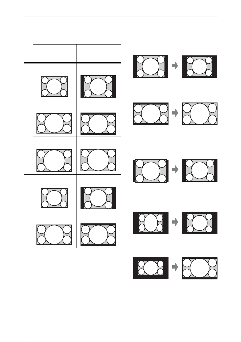
Aspect
VPL-SW635C/SW630C/SW620C/
SW630/SW620
Input signal Recommended
setting value and
projected image
4:3 Full1
16:9 Full1
*1 *2 *3
*1 *2 *3
Computer signal
16:10 Full1
4:3 4:3
*4 *5
*1: If you select “Normal,” the image is
projected in the same resolution as the
input signal without changing the aspect
ratio of the original image.
*2: If you select “Full2,” the image is projected
to fit the projected image size, regardless
of the aspect ratio of the image.
*3: If you adjust the projected image position
*3
using an image with 16:9 aspect ratio and
then switch the input source to 4:3 image,
the top and bottom edge of the image may
be hidden. In this a case, select “Full3.”
*4: Depending on the input signal, the
projected image may be projected as
illustrated below. In this a case, select
“16:9.”
24
The Screen Menu
16:9 16:9
Video signal
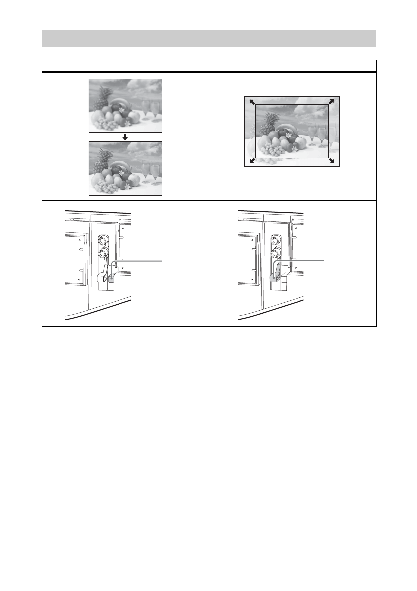
*5: Depending on the input signal, the image
may be projected as illustrated below. In
this a case, select “Zoom.”
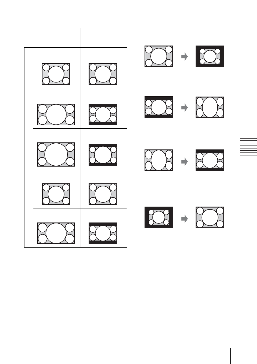
VPL-SX630
Input signal Recommended
4:3
16:9
setting value and
projected image
*1
Full1
*1 *2
Full1
*1: If you select “Normal,” the image is
projected in the same resolution as the
input signal without changing the aspect
ratio of the original image.
*2: If you select “4:3,” the image is projected
to fit the projected image size, regardless
of the aspect ratio of the image.
Computer signal
16:10 Full1
*1 *2
*3: Depending on the input signal, the
projected image may be projected as
illustrated below. In this a case, select
“16:9.”
Adjustments and Settings Using a Menu
4:3 4:3*3
*4: Depending on the input signal, the
projected image may be projected as
illustrated below. In this a case, select
“Zoom.”
16:9 16:9
*4
Video signal
The Screen Menu
25
The Function Menu
The Function menu is used for setting various functions of the projector.
Items Item descriptions
Volume The higher the value, the louder an audio volume and the lower the
Mic Volume Adjust the volume of the microphone.
Speaker On/Off: When set to “On,” speaker outputs sound. To not output
Smart APA On/Off: When set to “On,” APA functions automatically when a
CC Display CC1/CC2/CC3/CC4/Text1/Text2/Text3/Text4: Select the closed
Lamp Timer Reset When replacing the lamp, resets the lamp timer (page 74).
Start Up Image On/Off: When set to “On,” the Start Up Image is displayed on the
Interactive
(VPL-SW635C only)
Calibration Auto/Manual (Main)/Manual (Sub): Performs calibration for the PC
PC Free Interactive On/Off: If the computer and projector are not connected with the USB
Assign Type B
*9
USB
Whiteboard Data Retrieve to computer/Save to projector: If you select “Retrieve to
value, the lower the audio volume.
*2
sound from the speaker, select “Off.”
signal is input.
caption service (captions or text).
Off: Closed caption does not appear.
screen when the projector is powered on.
Free Interactive function (page 50) and the mouse mode function
(page 56). If you select “Auto”, the projector performs the calibration
automatically. If you select “Manual (Main),” the calibration for the
main pen will be performed manually. If you select “Manual (Sub),”
the calibration for the sub pen will be performed manually.
cable and you select “On,” the toolbar will be displayed. If you select
“Off,” the toolbar will not be displayed, and the PC Free Interactive
function cannot be used.
Off/Input-A/Input-B/Input-C/Network/Type B USB: Select the
image for when you use the Interactive Presentation Utility 2 or mouse
mode. If you select the same input terminal as the one selected for
“Input” (menu for switching the input signal) of the projected image
(page 14), you can use Interactive Presentation Utility 2 or mouse
mode on it. If you select “Off,” you cannot use Interactive Presentation
Utility 2 and mouse mode.
computer,” you can move the data, saved in whiteboard mode, via
USB cable to your computer. If you select “Save to projector,” you can
save the whiteboard data the projector is projecting by clicking the
save button on the main pen toolbar of the PC Free Interactive
function.
*1
*3 *4 *5
*6
*7 *8
Notes
*1: APA functions when a computer signal is input via the RGB input terminal (INPUT A/INPUT
B).
*2: The maximum available mic volume is set by the value of “Volume.”
26
The Function Menu

*3: Before performing the calibration, the message “Do you wish to start calibration?” will be
displayed. If you select “Yes”, the projector performs the calibration.
*4: If you already have started the Interactive Presentation Utility 2 on the computer, perform the
calibration of Interactive Presentation Utility 2.
*5: If you display the menu or the warning/caution messages etc., are displayed during the
calibration, calibration will stop. In addition, if you stop operating the calibration for more than
20 seconds, the manual calibration will also stop.
*6: When you display the menu while using the PC Free Interactive function, the PC Free Interactive
function cannot be used for a while and the toolbars and drawing data will not be displayed. If
you hide the menu, you can use the PC Free Interactive function again. If warning or notification
messages etc. appear, you cannot use the PC Free Interactive function. For the settings of PC
Free Interactive, see page 50.
*7: If you select “Save to projector” when you are accessing the whiteboard data in the projector,
the files may be damaged. Do not operate while you are accessing the whiteboard data.
*8: If “Retrieve to computer” is selected, you cannot save the whiteboard data to the projector even
if the computer and the projector are connected with the USB cable.
*9: Images may not be projected properly depending on the operating environment or the
application. Use Input-A, Input-B, or Input-C to project the images properly.
Adjustments and Settings Using a Menu
The Function Menu
27
The Operation Menu
The Operation menu is used for setting for the operations by using the menu or the remote
commander.
Items Item descriptions
Language Selects the language used in the menu and messages.
Status On: All on-screen statuses are enabled.
Security Lock
Control Key
Lock
Off: Turns off the on-screen displays, except for menus, warning messages
and messages from the message list.
*1
On/Off: This function enables restriction of the projector to authorized users
by password. The setting procedures for security locking are as follows:
1 Select “On” and press the ENTER key to display the setting menu.
2 Input the password with the MENU, V/v/B/b and ENTER keys. (The
default setting password is “ENTER, ENTER, ENTER, ENTER.”)
3 Input a new password with the MENU, V/v/B/b and ENTER keys.
4 Enter the password again to confirm.
Enter the password when you turn on the projector after disconnecting and
reconnecting the AC power cord.
When it is set to “Off,” you can cancel the security lock. You are required to
input the password again.
If you fail to enter the correct password after three consecutive times, the
projector cannot be used. In this case, press the ?/1 key to go Standby mode
then turn on the power again.
On/Off: When set to “On,” locks all the control panel keys of the projector.
However, you can operate the following when set to “On”:
• Press and hold the ?/1 key for approximately 10 seconds during Standby
mode.
c The projector turns on.
• Press and hold the MENU key for approximately 10 seconds during power
on.
c “Control Key Lock” is set to “Off” and enables operation of all keys on
the projector.
Note
*1: You will not be able to use the projector if you forget your password. If you call qualified Sony
personnel because you have forgotten the password, you will be asked to verify the projector’s
serial number and your identity. (This process may differ in other countries/regions.) Once your
identity has been confirmed, we will provide you with the password.
28
The Operation Menu
The Connection/Power Menu
The Connection/Power menu is used for setting for the connections and power.
Items Item descriptions
LAN Settings
IP Address
*9
Setup
WLAN Settings
*10
WLAN
Connection
WLAN
Network
*14
Input-A Signal Sel.
ECO
Lamp Mode High/Standard/Low/Auto
Constant
Brightness
Auto Power Saving
With No Input
With Static
*17
Signal
Standby Mode*
Auto (DHCP): The IP address is assigned automatically from the
DHCP server such as a router.
Manual: To specify the IP Address manually.
On/Off: Set the wireless output of the USB wireless LAN module (not
*8
supplied) to On/Off.
Access Pt. (Auto)/Access Pt. (Manual)/Client
*12
WLAN.
Auto/Computer/Video GBR/Component:
*11
: Changes modes for
When set to “Auto,” selects
the type of video signal input automatically when “Input-A” is selected.
*5 *7 *15
: When set to “High,” the image
becomes brighter, and power consumption becomes higher. When set to
“Low,” power consumption is minimized; however, the image will be
darker. When set to “Auto,” brightness is adjusted automatically
according to image content. Dark images are projected with brightness
adjusted, leading to energy-saving. Bright images are projected
brightly, without adjusting brightness.
On/Off: Available when the lamp mode is set to High. Outputs light at
a certain brightness.
*16
Lamp Cutoff: The lamp turns off automatically and power
*13
consumption is reduced if no signal is input for approx. 10 minutes.
The lamp lights again when a signal is input or any key is pressed. In
Lamp Cutoff, the ON/STANDBY indicator lights in orange. (page 68)
Standby*
6
: If no signal is input to the unit for approx. 10 minutes, the
power turns off automatically, and the unit enters standby mode.
Off: You can deactivate the With No Input.
Lamp Dimming
seconds, lamp output is gradually reduced (approximately 10% to
3
15%*
) from that set in the Lamp Mode. Automatically the lamp slowly
*4 *5 *7
: If an image does not change for about 10
darkens to approximately 30% of its lamp output according to the
selected time (with no change to input signal) “5,” “10,” “15,” “ 20”
minutes or “Demo.,” While dimming the lamp, the message “Lamp
Dimming” appears. If you select “Demo.,” the image will start to
darken about 40 seconds later. When any change in signal is detected,
or an operation (remote control or control panel) is performed, normal
brightness is restored.
Off: You can deactivate the With Static Signal.
2
Standard/Low: When set to “Low,” lowers power consumption in
Standby mode.
*1
Adjustments and Settings Using a Menu
The Connection/Power Menu
29

Items Item descriptions
Direct Power On On/Off: When set to “On,” you can turn the power on without going to
Standby mode when the AC power cord is connected to a wall outlet.
With the projector turned off, you can also unplug the AC power cord
without going to Standby mode, regardless of the Direct Power On
setting.
Notes
*1: This may not be optimum depending on the input signal. In this case set manually according
to the connected equipment.
*2: When “Standby Mode” is set to “Low,” the network and network control function cannot be
operated while the projector is in standby mode.
*3: This varies depending on the “Lamp Mode” setting.
*4: As the lamp is dimmed gradually, you may not notice any change in brightness. You might only
notice that the lamp has dimmed when its brightness is restored after there is a change in input
signal.
*5: This mode does not work for about three minutes after the lamp lights. A change in signal may
not be detected depending on the input image. The lamp may become brighter at intervals
during lamp dimming. However, this is not a malfunction. If With No Input is set, it takes
priority.
*6: Select “Off” to avoid entering standby mode when there is no input signal.
*7: Does not function when “Type A USB”, “Type B USB” or “Network” is selected as the input.
In this case, it becomes equivalent to “Standard.”
*8: Reflecting changes in WLAN settings may take a few moments.
*9: To set the IP address manually, select “Manual”, press “Apply”, then enter the IP address.
*10: When you send images or files from a tablet PC/smartphone and display them (page 61), set
“WLAN Network” to “Access Pt. (Auto)” or “Access Pt. (Manual),” to use USB wireless LAN
module IFU-WLM3 (not supplied) as a wireless access point.
*11: The factory default settings for “Access Pt. (Manual)” are as follows.
SSID: VPL + MAC address for LAN
Security Method: WEP(64bit)
Password: sony1
To change the settings for “Access Pt. (Manual)”, use a Web browser.
For details, see “Setting the WLAN Network of the projector” (page 38).
If “Access Pt. (Manual)” is set, when you use Presentation Function via Network (page 58),
select “Manual Connect” to connect to the network.
*12: For changing the settings for “Client,” use the Web browser for change. For details, see
“Setting the WLAN Network of the projector” (page 38).
*13: Constant Brightness mode will be enabled for about 2,000 hours after it is activated at early
usage. After this period, it will be disabled automatically. Activated time and brightness may
vary depending on the usage conditions.
*14: If the projector cannot connect wirelessly, click [Apply] once again to make sure the
connection is established. For details, see “Setting the WLAN Network of the projector”
(page 38).
*15: For VPL-SW635C, this does not function while the PC Free Interactive function is activated.
In this case, “Lamp Mode” becomes equivalent to “Standard” (page 33).
*16: For VPL-SW635C, this does not function when the PC Free Interactive function is activated.
In this case, “With No Input” will be “Off
” (page 33).
*17: For VPL-SW635C, this does not function when the PC Free Interactive function is activated.
In this case, “With Static Signal” will be “Off
” (page 33).
30
The Connection/Power Menu
 Loading...