

Sony VPL-S500U User Manual
3-860-598-12 (1)
LCD Data Pr ojector
Operating Instructions
Mode d’emploi
Manual de instrucciones
EN
F
E
VPL-S500U
VPL-S500E
VPL-S500M
1997 by Sony Corporation
English
WARNING
To prevent fire or shock hazard, do not
expose the unit to rain or moisture.
To avoid electrical shock, do not open the
cabinet. Refer servicing to qualified
personnel only.
This symbol is intended to alert the
user to the presence of uninsulated
“dangerous voltage” within the
product’s enclosure that may be of
sufficient magnitude to constitute a risk
of electric shock to persons.
This symbol is intended to alert the
user to the presence of important
operating and maintenance (servicing)
instructions in the literature
accompanying the appliance.
For the customers in the USA
This equipment has been tested and found to comply with
the limits for a Class B digital device, pursuant to Part 15 of
the FCC Rules. These limits are designed to provide
reasonable protection against harmful interference in a
residential installation. This equipment generates, uses, and
can radiate radio frequency energy and, if not installed and
used in accordance with the instructions, may cause harmful
interference to radio communications. However, there is no
guarantee that interference will not occur in a particular
installation. If this equipment does cause harmful
interference to radio or television reception, which can be
determined by turning the equipment off and on, the user is
encouraged to try to correct the interference by one or more
of the following measures:
– Connect the equipment into an outlet on a circuit different
from that to which the receiver is connected.
– Consult the dealer or an experienced radio/TV technician
for help.
You are cautioned that any changes or modifications not
expressly approved in this manual could void your authority
to operate this equipment.
For the customers in Canada
This Class B digital apparatus meets all requirements of the
Canadian Interference-Causing Equipment Regulations.
For the customers in the United Kingdom
WARNING
THIS APPARATUS MUST BE EARTHED
IMPORTANT
The wires in this mains lead are coloured in accordance with
the following code:
Green-and-Yellow: Earth
Blue: Neutral
Brown: Live
As the colours of the wires in the mains lead of this
apparatus may not correspond with the coloured markings
identifying the terminals in your plug proceed as follows:
The wire which is coloured green-and-yellow must be
connected to the terminal in the plug which is marked by the
letter E or by the safety earth symbol Y or coloured green or
green-and-yellow.
The wire which is coloured blue must be connected to the
terminal which is marked with the letter N or coloured black.
The wire which is coloured brown must be connected to the
terminal which is marked with the letter L or coloured red.
Voor de klanten in Nederland
Bij dit produkt zijn batterijen geleverd.
Wanneer deze leeg zijn, moet u ze niet
weggooien maar inleveren als KCA.
The socket-outlet should be installed near the equipment
and be easily accessible.
– Reorient or relocate the receiving antenna.
– Increase the separation between the equipment and
receiver.
2 (EN)
Table of Contents
Overview
Precautions ................................................................4 (EN)
Features......................................................................6 (EN)
Location and Function of Controls..........................7 (EN)
Setting up and projecting
Installing the Projector............................................13 (EN)
Connecting with a Computer or a VCR ................. 14 (EN)
Operating a computer from the Remote
Commander ......................................................... 15 (EN)
Projecting ................................................................. 16 (EN)
Adjustments and settings using the menu
Using the MENU.......................................................19 (EN)
The INPUT SELECT Menu.......................................20 (EN)
The PICTURE CTRL Menu ...................................... 21 (EN)
The INPUT SETTING Menu ..................................... 23 (EN)
The SET SETTING Menu ......................................... 26 (EN)
The INPUT INFO Menu ............................................ 29 (EN)
Installation/connection examples
Installation Examples..............................................30 (EN)
Connection Example ...............................................32 (EN)
Maintenance
Maintenance.............................................................33 (EN)
Floor Installation.....................................................30 (EN)
Ceiling Installation..................................................31 (EN)
Connecting 15k RGB/Component Equipment .......32 (EN)
Replacing the Lamp ................................................33 (EN)
EN
English
Other
Cleaning the Air Filter ............................................33 (EN)
Troubleshooting ...................................................... 34 (EN)
Specifications .......................................................... 36 (EN)
Index ......................................................................... 40 (EN)
3 (EN)
Precautions
On safety
•Check that the operating voltage of your unit is identical with the voltage
of your local power supply. If voltage adaptation is required, consult with
qualified Sony personnel.
•Should any liquid or solid object fall into the cabinet, unplug the unit and
have it checked by qualified personnel before operating it further.
•Unplug the unit from the wall outlet or set the MAIN POWER switch to
OFF if it is not to be used for several days.
•To disconnect the cord, pull it out by the plug. Never pull the cord itself.
•The wall outlet should be near the unit and easily accessible.
•The unit is not disconnected from the AC power source (mains) as long
as it is connected to the wall outlet, even if the unit itself has been turned
off.
•Do not look into the lens while the lamp is on.
•Do not place your hand or objects near the ventilation holes — the air
coming out is hot.
On installation
•When the projector is mounted on the ceiling, the Sony PSS-500
Projector Suspension Support must be used for installation.
•Allow adequate air circulation to prevent internal heat build-up. Do not
place the unit on surfaces (rugs, blankets, etc.) or near materials (curtains,
draperies) that may block the ventilation holes. Leave space of more than
10 cm (4 inches) between the wall and the projector. Be aware that room
heat rises to the ceiling; check that the temperature near the installation
location is not excessive.
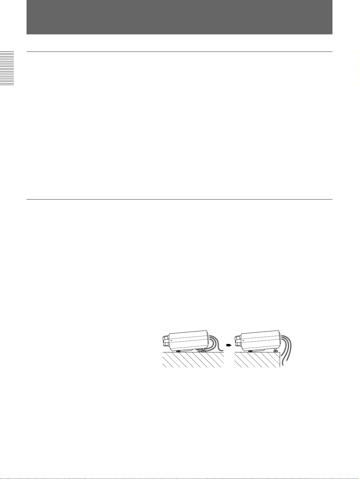
•If you use the rear adjuster in a warm environment, the exhaust may be
inhaled into the projector through the ventilation holes at the bottom,
causing the internal temperature to rise, which activates the protection
circuit. Install the projector so that the exhaust is not blocked. (See the
illustration below.)
4 (EN)
•Install the projector on the floor or ceiling. Any other installation causes
a malfunction such as color irregularity or shortening lamp life.
•Do not install the unit in a location near heat sources such as radiators or
air ducts, or in a place subject to direct sunlight, excessive dust or
humidity, mechanical vibration or shock.
•To avoid moisture condensation, do not install the unit in a location
where the temperature may rise rapidly.
On illumination
•To obtain the best picture, the front of the screen should not be exposed
to direct lighting or sunlight.
•Ceiling-mounted spot lighting is recommended. Use a cover over
fluorescent lamps to avoid lowering the contrast ratio.
•Cover any windows that face the screen with opaque draperies.
•It is desirable to install the projector in a room where floor and walls are
not of light-reflecting material. If the floor and walls are of reflecting
material, it is recommended that the carpet and wall paper be changed to
a dark color.
On preventing internal heat build-up
After you turn off the power with the POWER key on the control panel or
the Remote Commander, do not press the MAIN POWER switch while the
cooling fan is still running.
Caution
The projector is equipped with ventilation holes (intake) at the bottom and
ventilation holes (exhaust) on the rear. Do not block or place anything near
these holes, or internal heat build-up may occur, causing picture
degradation or damage to the projector.
Overview
On cleaning
On repacking
•To keep the cabinet looking new, periodically clean it with a soft cloth.
Stubborn stains may be removed with a cloth lightly dampened with a
mild detergent solution. Never use strong solvents, such as thinner,
benzene, or abrasive cleansers, since these will damage the cabinet.
•Avoid touching the lens. To remove dust on the lens, use a soft dry cloth.
Do not use a damp cloth, detergent solution, or thinner.
•Clean the filter at regular intervals.
•Save the original shipping carton and packing material; they will come in
handy if you ever have to ship your unit. For maximum protection,
repack your unit as it was originally packed at the factory.
5 (EN)

Features
High brightness, high picture quality
•High brightness
Adopting the long service life, the 250 W, metal halide lamp and new
developed optical system allow high brightness (light output 450 ANSI
lumen) and excellent uniformity on the picture.
Easy presentation
Easy setup
•High resolution
By adopting three 1.3-inch, about 520,000-pixel S VGA
projector offers resolution of 832 × 624 pixels for RGB input and 600
horizontal TV lines for composite video input.
•Superior color reproduction
The superior characteristics of the metal halide lamp and the optical
design of the projector allow superior color reproduction.
•Remote Commander with mouse control function
The Remote Commander can control a mouse for a computer connected
to the mouse receiver.
•High portability
This projector comes with convenient features for transportation such as a
carrying handle and a Remote Commander pocket on the cabinet to keep
the Remote Commander.
1)
panels, this
•Easy setup with external equipment
This projector has 19 kinds of preset data for input signals. You can get
an optimum picture by simply connecting an equipment with supplied
cable.
•Flexible setup
This projector is designed to be installed on the table or the ceiling.
A 1.5x zoom lens is provided as standard equipment.
Accepts various input signals
This projector accepts horizontal frequencies of 15, 24 to 57 kHz and
vertical frequencies of 50 to 85 Hz. You can project pictures from VGA or
XGA computers, VCRs, and video cameras.
•Compatible with five color systems
NTSC, PAL, SECAM, NTSC 4.43
selected automatically or manually.
..........................................................................................................................................................................................................
1) S VGA is a registered trademark of the International Business Machines Corporation, U.S.A.
2) NTSC4.43 is the color system used when playing back a video recorded on NTSC on a NTSC4.43 system VCR.
2)
, or PAL-M color system can be
6 (EN)
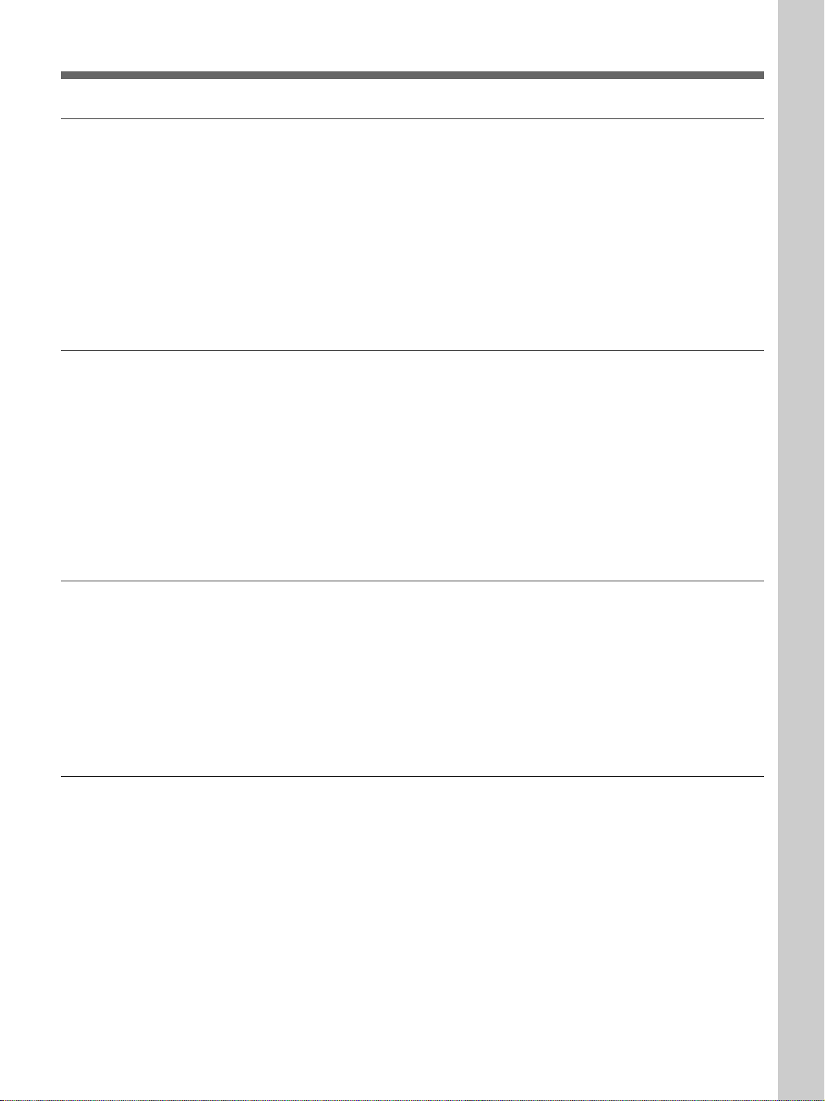
Location and Function of Controls
Front
1!¡!º
2
3
4
567 9
8
1 Speakers
2 Front remote control detector
3 Remote Commander pocket
Houses the supplied Remote Commander. When
inserting the Remote Commander, make sure the
infrared transmitter is facing forwards and push it until
it clicks.
To take out the Remote Commander from the pocket,
push it once and pull it out.
How to open and close the
connector cover
To open the cover, pull it
down.
To close the cover, pull it up
until it locks.
0 Control panel
For details, see page 8 (EN).
!¡ Lamp cover
How to use the adjusters
4 Lens
Remove the lens cap before projection.
5 Focus ring
Adjusts the picture focus.
6 Zoom ring
Adjusts the size of the picture.
7 Carrying handle
Use the handle for carrying the projector.
8 Adjusters
Use the adjusters to keep the projector level if it is
installed on an uneven surface.
9 Connector panel
For details, see page 9 (EN).
To lower
the projector
To raise
the projector
While lifting the projector, turn the adjusters and
adjust the height so that the projector becomes level.
There are two adjusters at the front and one at the rear
of the projector.
Note
Be careful not to let the projector down on your
fingers.
7 (EN)
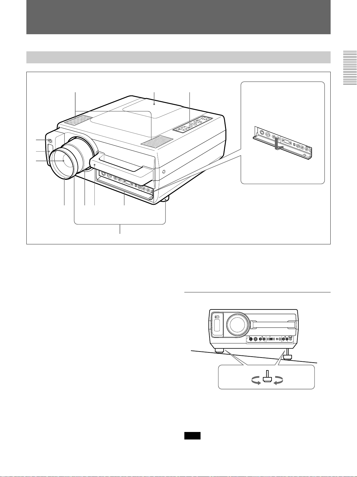
Location and Function of Controls
Control panel
PATTERN PICTURE
MUTING VOLUME
AUDIO LIGHT
RESET
MENU
ENTER
INPUT
SELECT
POWER
STANDBY
u
3456789!º!¡
LAMP
TEMP
POWER
1
2
1 POWER key
Press to turn the projector on and off once the
projector is in the standby mode. The POWER
indicator lights in green when the power is turned on.
When turning off the power, press the POWER key
twice following the message on the screen, or press
and hold the key for about one second.
For details on steps for turning off the power, see “To turn off
the power” on page 17 (EN).
2 LIGHT key
Lights the back lighting (orange) for the control panel
when the power is turned on. Press again to turn off
the back lighting.
3 Indicators
POWER: Lights in green when the power is turned
on.
Flashes in green while the cooling fan runs after
turning off the power with the POWER key. The
fan runs for about 90 seconds after turning off the
power.
The POWER indicator flashes quickly for the first
minute. During this time, you will not be able to
turn the power back on with the POWER key.
STANDBY: Lights in red when the MAIN POWER
switch at the rear of the projector is turned on.
Once in the standby mode, you can turn the
projector on with the POWER key on the control
panel or the Remote Commander.
Note
When the MAIN POWER switch is turned off,
there will be a slight delay before the indicator goes
off.
LAMP: Lights up or flashes under the following
conditions:
• Lights up when a trouble has prevented the lamp
from lighting.
• Flashes when the lamp cover or air filter cover is
not secured firmly.
Note
When the LAMP indicator lights up, never open the
lamp cover if the projector is installed on the
ceiling.
TEMP (Temperature): Lights up or flashes under
the following conditions:
• Lights up when temperature inside the projector
becomes unusually high.
• Flashes when the fan inside the projector stops.
For details on the LAMP and the TEMP indicators, see page
35 (EN) .
4 INPUT SELECT key
Selects the input signal. Each time the key is pressed,
the video signal is switched between the VIDEO IN
and INPUT A connectors and the audio signal is
switched between the AUDIO IN L/R jacks and
INPUT A connectors.
5 MENU key
Press to display the on-screen menu. Press again to
clear the menu.
6 ENTER key
Press to enter the settings of items in the menu system.
7 Arrow keys (V/v/B/b)
Used to move the on-screen cursor or to make various
adjustments.
8 RESET key
Press to restore the value of an item back to its factory
preset value. This key functions when the menu or a
setting item is displayed on the screen.
9 VOLUME +/– keys
Adjust the volume of the built-in speakers and output
level of the AUDIO OUT jacks.
+ : Increases the volume.
– : Decreases the volume.
8 (EN)
0 MUTING keys
Cuts off the picture and sound.
PICTURE: Press to cut off the picture. Press again
to restore the picture.
AUDIO: Press to cut off the sound. Press again or
press the VOLUME + key to restore the sound.
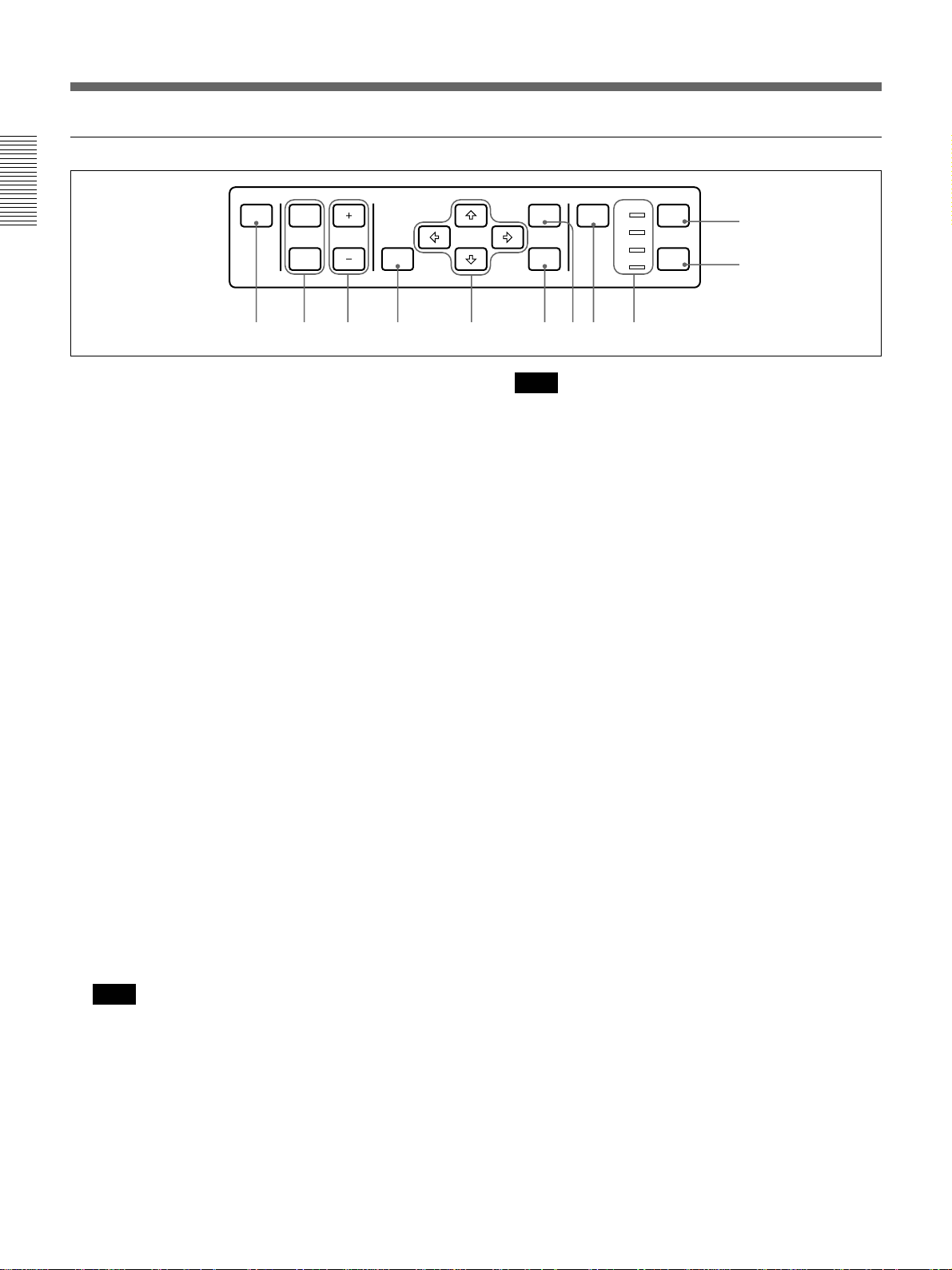
Connector panel
!¡ PATTERN key
Display a pattern on the screen for focus adjustment.
Press again to clear the pattern.
S VIDEO VIDEO
VIDEO IN AUDIO IN
12 34 5
1 VIDEO IN connectors
S VIDEO (mini DIN 4-pin): Connects to the S video
output (Y/C video output) of a video equipment.
VIDEO (BNC-type): Connects to the composite
video output of video equipment.
Note
If you have video equipments connected to both the S
VIDEO and VIDEO connectors, the signal from the S
VIDEO is selected. When showing video connected to
the VIDEO connector, be sure not to connect a cable to
the S VIDEO connector.
2 AUDIO IN L (MONO)/R jacks (phono type)
Connect to the audio output jacks of an equipment. For
stereo equipment, use both the L and R jacks; for
monaural equipment, use the L (MONO) jack only.
L (MONO) R
INPUT A
OFF
AUDIO IN
LR
AUDIO OUT
CONTROL S IN
75Ω
ON
4 AUDIO OUT L/R jacks (phono type)
Connects to external active speakers.
The volume of the speakers can be controlled by the
VOLUME keys on the projector or the Remote
Commander.
5 CONTROL S IN/PLUG IN POWER (DC 5V)
jack (stereo minijack)
Connects to the CONTROL S OUT jack of the
supplied Remote Commander when using as a wired
Remote Commander.
3 INPUT A connectors
RGB input connector (HD D-sub 15-pin, female):
Connect to the monitor output connector on a
computer using the supplied cable. Use the
optional cable to input a component signal.
75-ohm termination switch (ON/OFF): Normally
set to ON. Set it to OFF when the projector is
connected to a computer and a monitor.
AUDIO IN jacks (stereo minijack): Connects to the
audio output jack on a computer.
9 (EN)
Location and Function of Controls
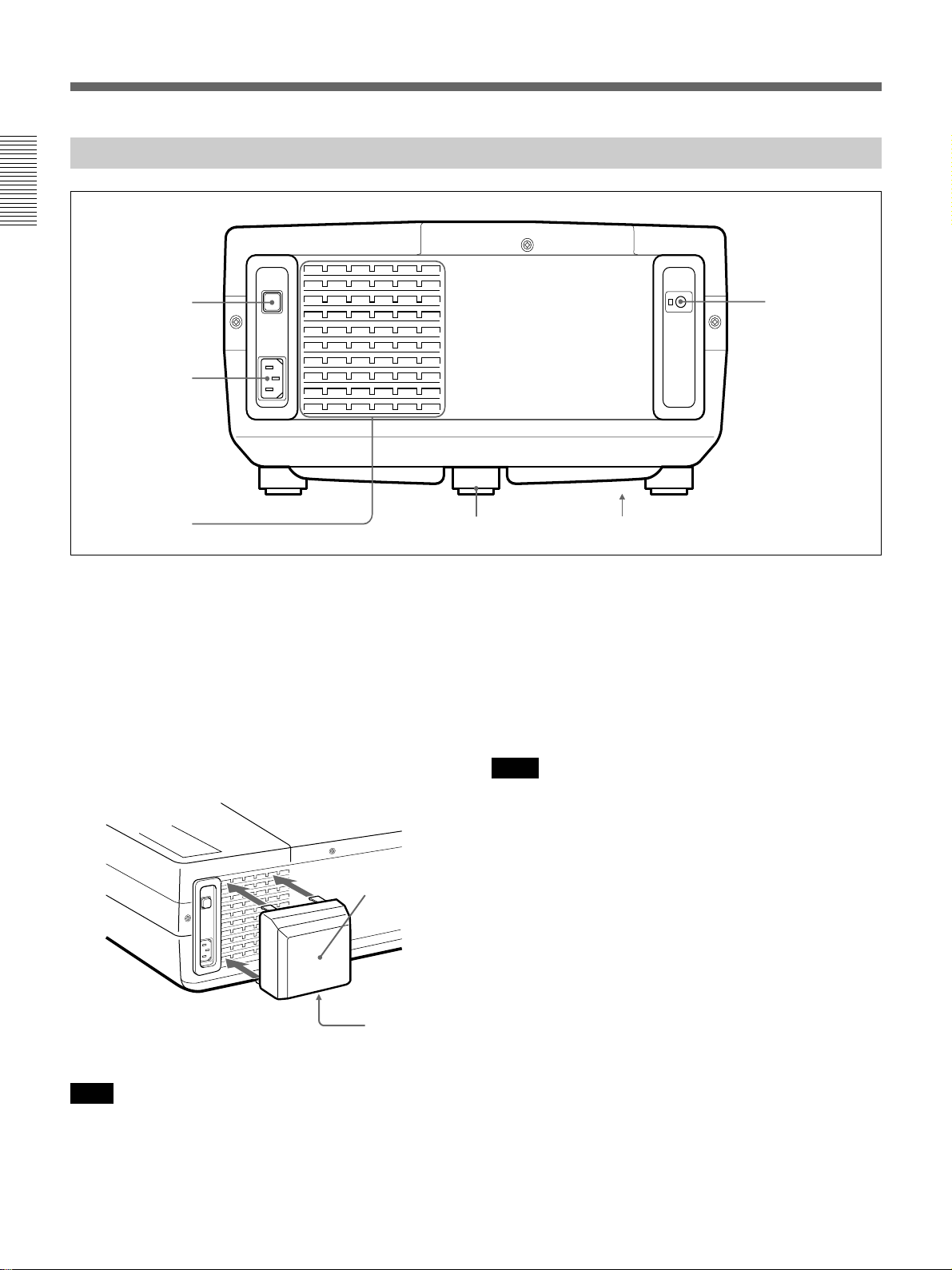
Rear
1
2
3
1 MAIN POWER switch (OON/oOFF)
Turns the main power on and off.
2 AC IN socket
Connect the supplied AC Power cord.
3 Ventilation holes (exhaust)
If you need to reduce the fan noise, install the supplied
ventilation cover over the holes.
6
54
4 Adjuster
Use the adjuster to keep the projector level if it is
installed on an uneven surface.
For details on using the adjuster, see “How to use the adjuster”
on page 7 (EN) .
5 Ventilation holes (intake)
Notes
•Do not place anything near the ventilation holes as it
may cause internal heat build-up.
•Do not place your hand or objects near the ventilation
holes – the air coming out is hot.
Ventilation
cover
The exhaust
opening should
face down.
Note
If the supplied AC power cord plug does not match the
wall socket in your country, consult qualified Sony
personnel.
10 (EN)
6 Rear remote control detector
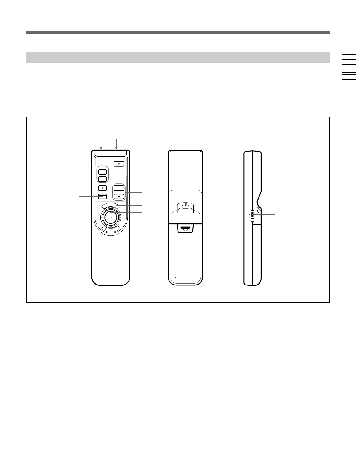
Remote Commander
The Remote Commander may be used as a wireless or
wired Remote Commander.
For details on operation of the keys not mentioned
here, see the description in the control panel section.
9!º
8
7
6
MUTING
PIC
AUDIO
INPUT
POWER
VOLUMERESET
N
U
E
M
1
2
3
4
E
R
N
E
5
T
If you connect the mouse receiver to a computer, you
can use the Remote Commander as a mouse for a
connected computer.
For details, see “Operating a Computer from the Remote
Commander” on page 15 (EN).
5
!¡
MOUSE MENU
Front
1 POWER key
2 VOLUME +/– keys
3 MENU key
4 Joy stick
Used to move the on-screen cursor or to make various
adjustments.
5 ENTER keys
6 RESET key
7 INPUT key
8 MUTING PIC/AUDIO keys
The MUTING PIC key has the same function as the
MUTING PICTURE key on the control panel.
Rear
Side
9 CONTROL S OUT jack (stereo minijack)
Connect to the CONTROL S IN jack on the projector
when using the Remote Commander as a wired
Remote Commander. When using the Remote
Commander as a wired Remote Commander by
connecting a stereo remote commander cable, you do
not need to install the batteries since the power is
supplied from the CONTROL S IN jack on the
projector.
0 Infrared transmitter
!¡ MOUSE/MENU switch
Normally, set to MENU.
Set to MOUSE when you operate the mouse on a
computer connected to the mouse receiver from the
Remote Commander.
For details, see “Operating a Computer from the Remote
Commander” on page 15 (EN).
11 (EN)
Location and Function of Controls
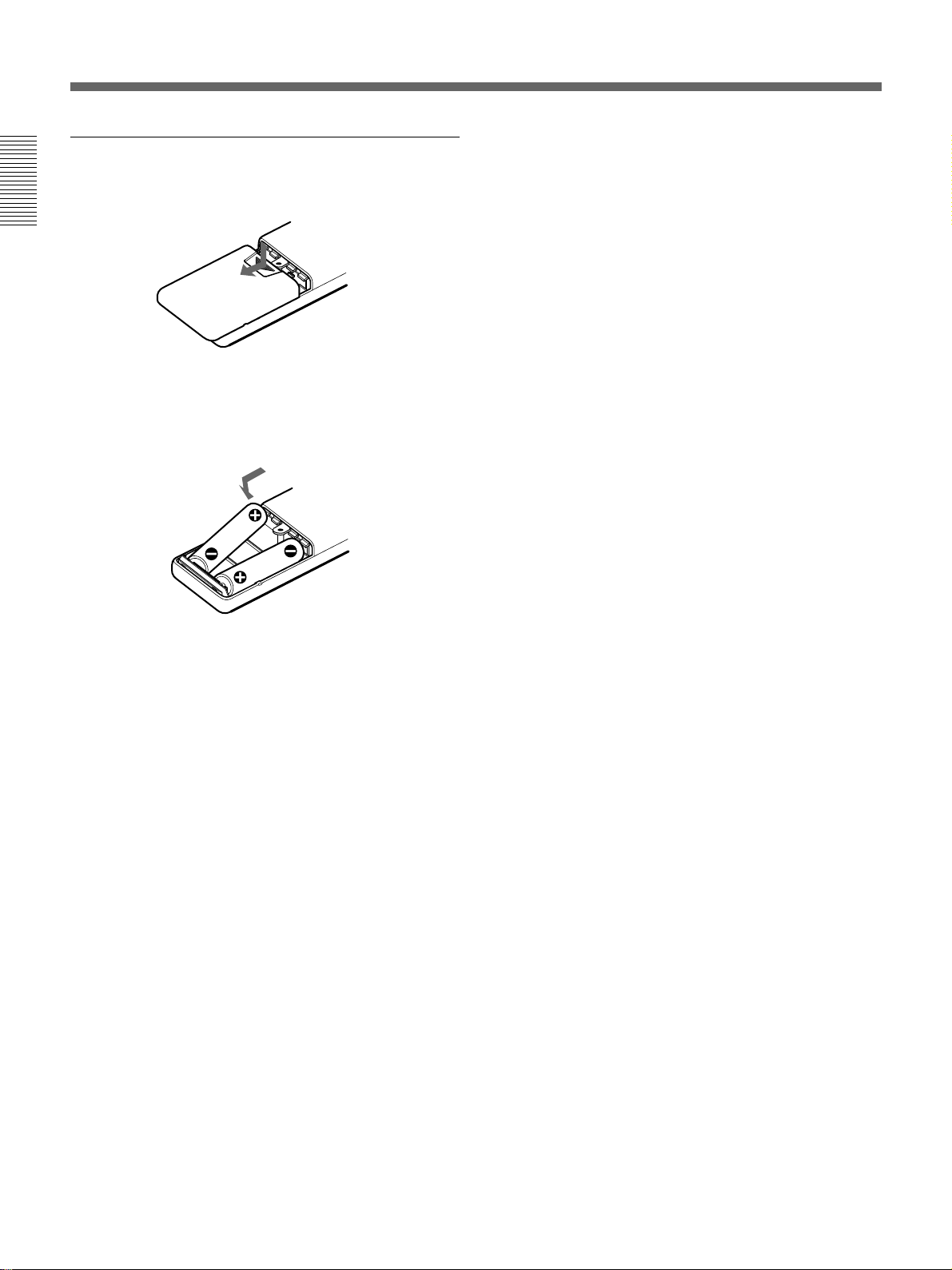
Battery installation
1 Push and slide to open the lid.
2 Install the two size AA (R6) batteries (supplied)
with the correct polarity.
Be sure to install
the battery from
the ’ side.
•The remote control detectors on the projector do not
operate when the Remote Commander is being used
as a wired Remote Commander. If you wish to use
the Remote Commander as a wireless Remote
Commander, be sure to remove the connecting cable
from both the Remote Commander and the projector.
3 Replace the lid.
Notes on batteries
•Be careful that the battery orientation is correct when
inserting batteries.
•Do not mix old battery with new one, or different
types of batteries.
•If you do not intend to use the Remote Commander
for a long time, remove the batteries to avoid damage
from battery leakage. If a battery has leaked, remove
the batteries, wipe the battery compartment dry and
replace the batteries with new ones.
Notes on wireless Remote Commander
operation
•Be sure that there is nothing to obstruct the infrared
beam between the Remote Commander and the
projector.
•The operation range is limited. The shorter the
distance between the Remote Commander and the
projector, the wider the angle within which the
commander can control the projector.
12 (EN)
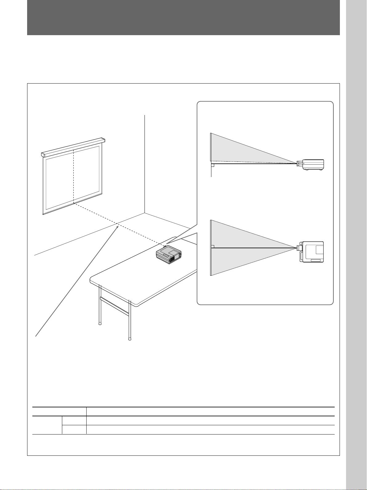
Installing the Projector
This section describes the installation arrangements for installing the
projector on a table. For ceiling installation, consult with qualified Sony
personnel (see page 31 (EN)).
Horizontal center
of the screen
Setting up and projecting
Adjust the vertical and horizontal positioning of the
projector.
Vertical positioning (side view)
Adjust the height of the projector so that the center of
the lens is just below the bottom edge of the screen.
Horizontal positioning (top view)
Adjust the horizontal positioning of the projector so
that the lens is aligned with the horizontal center of the
screen.
The distance between the lens and the screen varies depending on the size of the
screen. Use the following table as a guide.
The following table shows the projection distance when the Macintosh 16-inch mode
signal (horizontal 832 × vertical 624 dots) is input.
• When XGA signal is input, the projection distance becomes longer by 1.5%.
• When S VGA (800 × 600 dots) or video signal is input, the projection distance
becomes longer by 4%.
• When VGA (640 × 480 dots) signal is input, the projection distance becomes longer
by 30%.
Unit: m (feet)
Screen size (inches) 40 60 80 100 120 150 180 200 250 300
Distance
Minimum 1.5 (4.8) 2.3 (7.4) 3.0 (10.0) 3.8 (12.5) 4.6 (15.1) 5.8 (18.9) 7.0 (22.8) 7.7 (25.4) 9.7 (31.8) 11.6 (38.2)
Maximum 2.2 (7.2) 3.3 (10.9) 4.5 (14.6) 5.6 (18.3) 6.7 (22.0) 8.4 (27.6) 10.1 (33.2) 11.3 (36.9) 14.1 (46.2) 16.9 (55.5)
For detailed information on installation measurements, see page 30 (EN).
13 (EN)
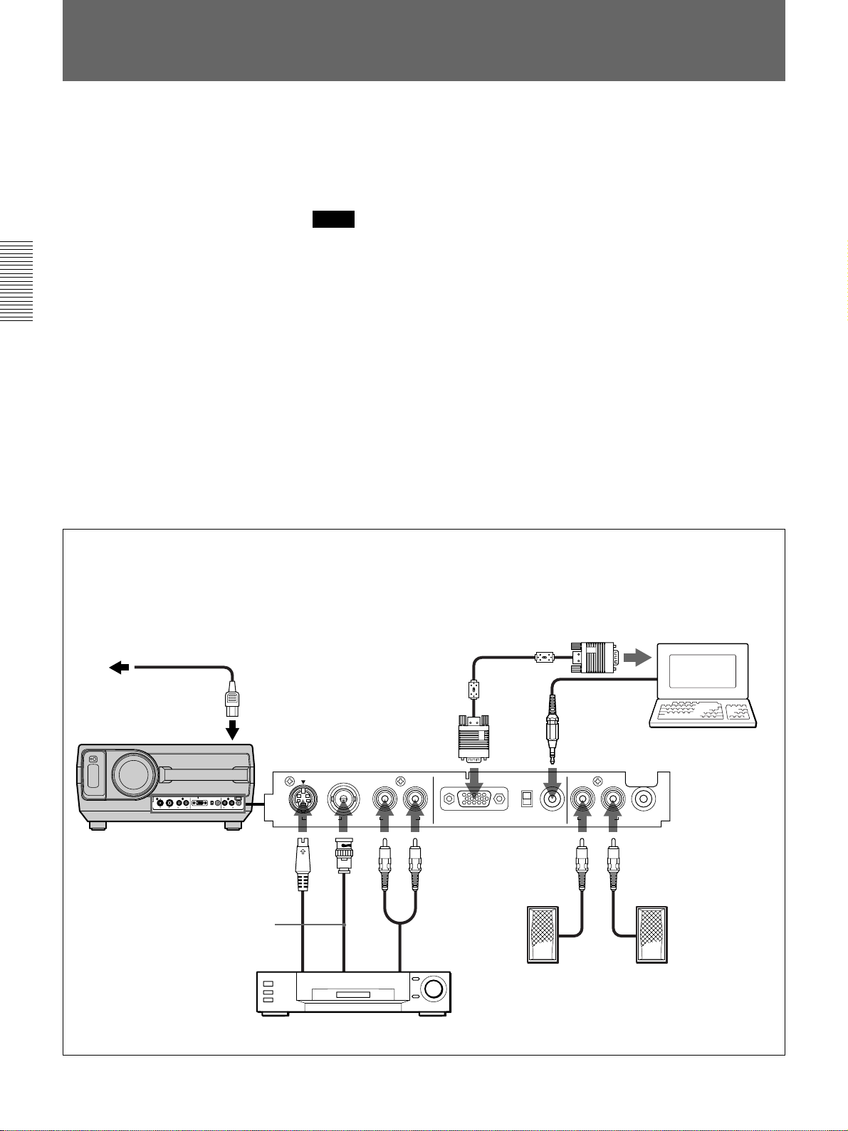
Connecting with a Computer or a VCR
This section describes how to connect the projector with a computer or a
VCR and external active speakers. For details on how to connect other
equipment, see page 32 (EN).
Also refer to the instruction manuals of the equipment to be connected.
Notes
•This unit accepts the VGA, S VGA, and XGA signals. However, we
recommend you to set the output mode of your computer to the S VGA
mode for the external monitor.
•If you set your computer, such as a note-type IBM PC/AT compatible, to
output the signal to both the display of your computer and the external
monitor, the picture may not appear properly. In such cases, set the output
mode of your computer to output the signal to only the external monitor.
For details, refer to the operating instructions supplied with your computer.
When making connections, be sure to:
•turn off all equipment before making any connections.
•use the proper cables for each connection.
•insert the plugs of the cables properly; plugs that are not fully inserted
often generate noise. When pulling out a cable, be sure to pull it out from
the plug, not the cable itself.
For details on the DIP switch setting of the adapter, see page 38 (EN).
Use the supplied adapter when
connecting with a Macintosh1) computer.
to a wall outlet
Front
AC power cord
(supplied)
to AC IN
S-Video cable (not supplied)
Video cable
(not supplied)
to S VIDEO OUT
S VIDEO VIDEO
VIDEO IN AUDIO IN
to
VIDEO
OUT
HD D-sub 15-pin cable
(supplied)
L (MONO) R
Audio cable
(not supplied)
to AUDIO OUT
INPUT A
OFF
Computer
Audio cable (not supplied)
75Ω
ON
LR
AUDIO IN
AUDIO OUT
Active speakers
CONTROL S IN
VCR
..........................................................................................................................................................................................................
14 (EN)
1) Macintosh is a registered trademark of Apple Computer, Inc.
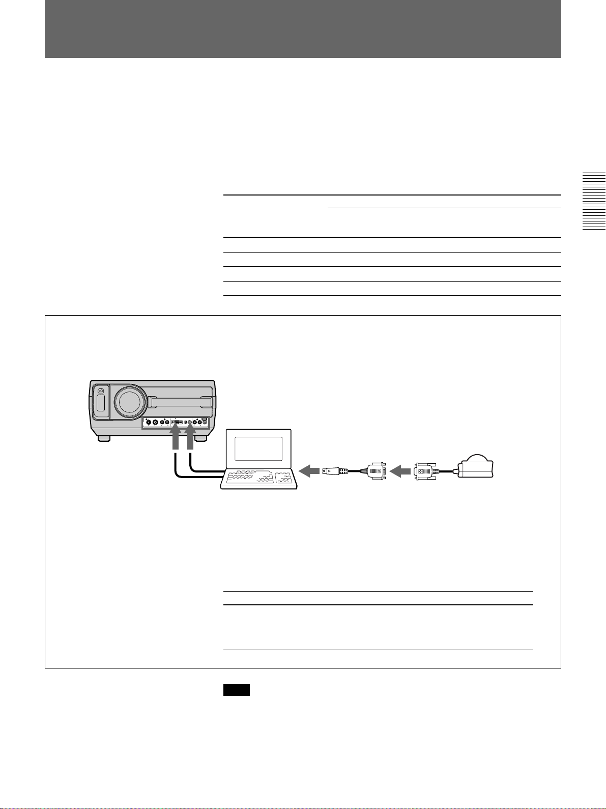
Operating a Computer from the Remote Commander
If you connect the supplied mouse receiver to the mouse port of a
computer, you can operate the mouse function of a computer with the
Remote Commander.
Set the MOUSE/MENU switch to MOUSE when you operate a computer
connected to the mouse receiver from the Remote Commander.
When the MENU/MOUSE switch is set to MOUSE, the MENU, ENTER
keys and joy stick on the Remote Commander function as follows.
Key and joy stick
MENU Left button Mouse button
ENTER (front) Right button Mouse button
ENTER (rear) Right button Mouse button
Joy stick Corresponds with the movements of the mouse
When using an IBM PC/AT compatible computer
For details, see the supplied RM-PJ21 operating instructions.
Front
Computer
IBM PC/AT
compatible, Serial
Cable for IBM PC/AT
compatible computers
or cable for Macintosh
computer
to mouse port
Function
1)
Macintosh
Mouse receiver
When your computer has a serial port, you
can directly connect the mouse receiver cable
to the port.
When you connect to the IBM PC/AT
compatible or Macintosh computer, use the
supplied conversion cables .
Computer
Conversion
cable
Note
IBM PC/AT compatible
Cable for IBM (for PC/AT
compatible computer, PS/2
type)
(Mini DIN 6-pin˜D-sub 9-pin)
Macintosh
Cable for
Macintosh
(Mini DIN 4-pin˜
D-sub 9-pin)
Be sure that there is nothing to obstruct the infrared beam between the
Remote Commander and the mouse receiver.
..........................................................................................................................................................................................................
1) IBM PC/AT is a registered trademark of International Business Machines Corporation, U.S.A.
15 (EN)
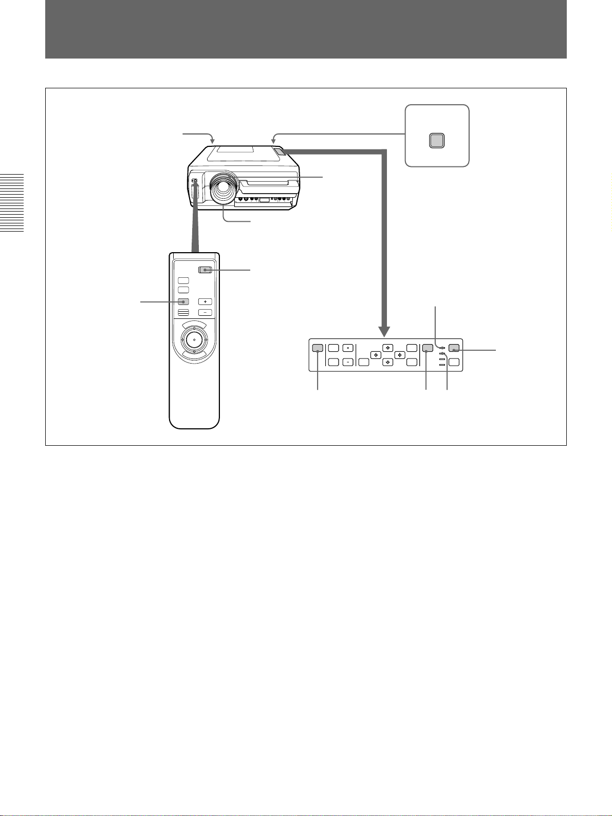
Projecting
Rear remote control
detector
Front remote control
detector
3
MUTING
PIC
AUDIO
INPUT
1
MAIN
POWER
O ON ⁄ o OFF
5
4, 6
POWER
2
VOLUMERESET
N
E
U
M
PATTERN PICTURE
E
N
R
T
E
MUTING VOLUME
RESET
AUDIO LIGHT
4
POWER indicator
POWER
INPUT
MENU
SELECT
STANDBY
u
ENTER
LAMP
TEMP
STANDBY indicator
3
POWER
2
1 Press the MAIN POWER switch on the rear of the projector (O ON).
The STANDBY indicator lights in red and the projector goes into the
standby mode.
2 Press the POWER key on the Remote Commander or the control
panel.
The POWER indicator lights in green.
3 Switch on equipment connected to the projector. Press the INPUT
SELECT key on the control panel or the INPUT key on the Remote
Commander to select the input source.
INPUT A: Selects audio and video signals input from the INPUT A
connectors.
VIDEO: Selects signal input from the VIDEO IN connectors and
AUDIO IN L/R jacks.
(If you have made connections to both the S VIDEO and
the VIDEO connectors, the signal from the S VIDEO
connector is selected.)
16 (EN)
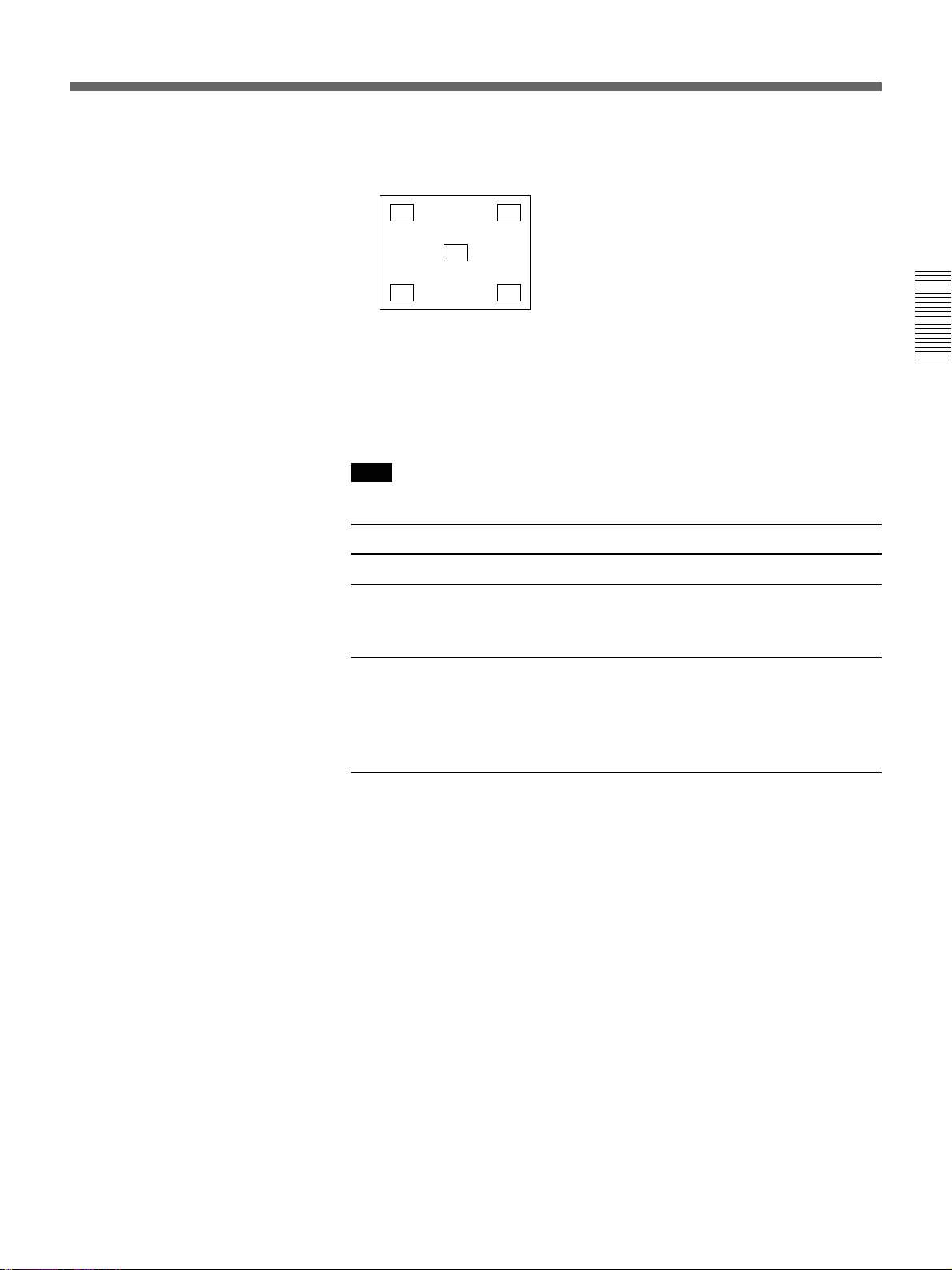
4 Press the PATTERN key on the control panel to display the H test
pattern, and turn the focus ring to adjust the focus.
HHHH HHHH
HHHH HHHH
HHHH
HHHH
HHHH HHHH
HHHH HHHH
Press the PATTERN key again to clear the pattern.
5 Turn the zoom ring to adjust the size of the picture.
6 Turn the focus ring again to adjust the focus.
Note
Do not look into the lens when the projector lamp is on.
To Press
Adjust the volume the VOLUME +/– keys.
Cut off the sound the AUDIO MUTING key. To restore
the sound, press the AUDIO MUTING
key again or press the VOLUME + key.
Cut off the picture the PICTURE MUTING key (PIC
MUTING key on the Remote
Commander). To restore the picture,
press the PICTURE MUTING key
again.
17 (EN)
Projecting
To turn off the power
1 Press the POWER key on the control panel or the Remote
Commander.
The following message appears to verify if you really want to turn off
the power.
POWER OFF?
Please press
POWER
key again.
Note
The message will disappear if you press a key except the POWER key,
or if you do not press any key for five seconds.
2 Press the POWER key again on the control panel or the Remote
Commander.
The POWER indicator flashes in green and the fan continues to run for
about 90 seconds to reduce the internal heat. The POWER indicator
flashes quickly for the first minute. During this time, you will not be
able to turn the power back on with the POWER key. After about one
minute, you can turn on the power with the POWER key.
3 Wait until the fan stops running and the STANDBY indicator lights in
red; then press the MAIN POWER switch to turn off the main power
(o OFF).
When you cannot confirm the on-screen message
When you cannot confirm the on-screen message in a certain condition,
you can turn off the power by holding the POWER key on the control
panel or the Remote Commander for about one second.
Notes
• Do not press the MAIN POWER switch while the fan is still
running; the fan will stop while the lamp is still hot, leading to
breakdown.
• To make the lamp life last longer, do not turn off the power at
least for about 10 minutes after turning on the power.
18 (EN)
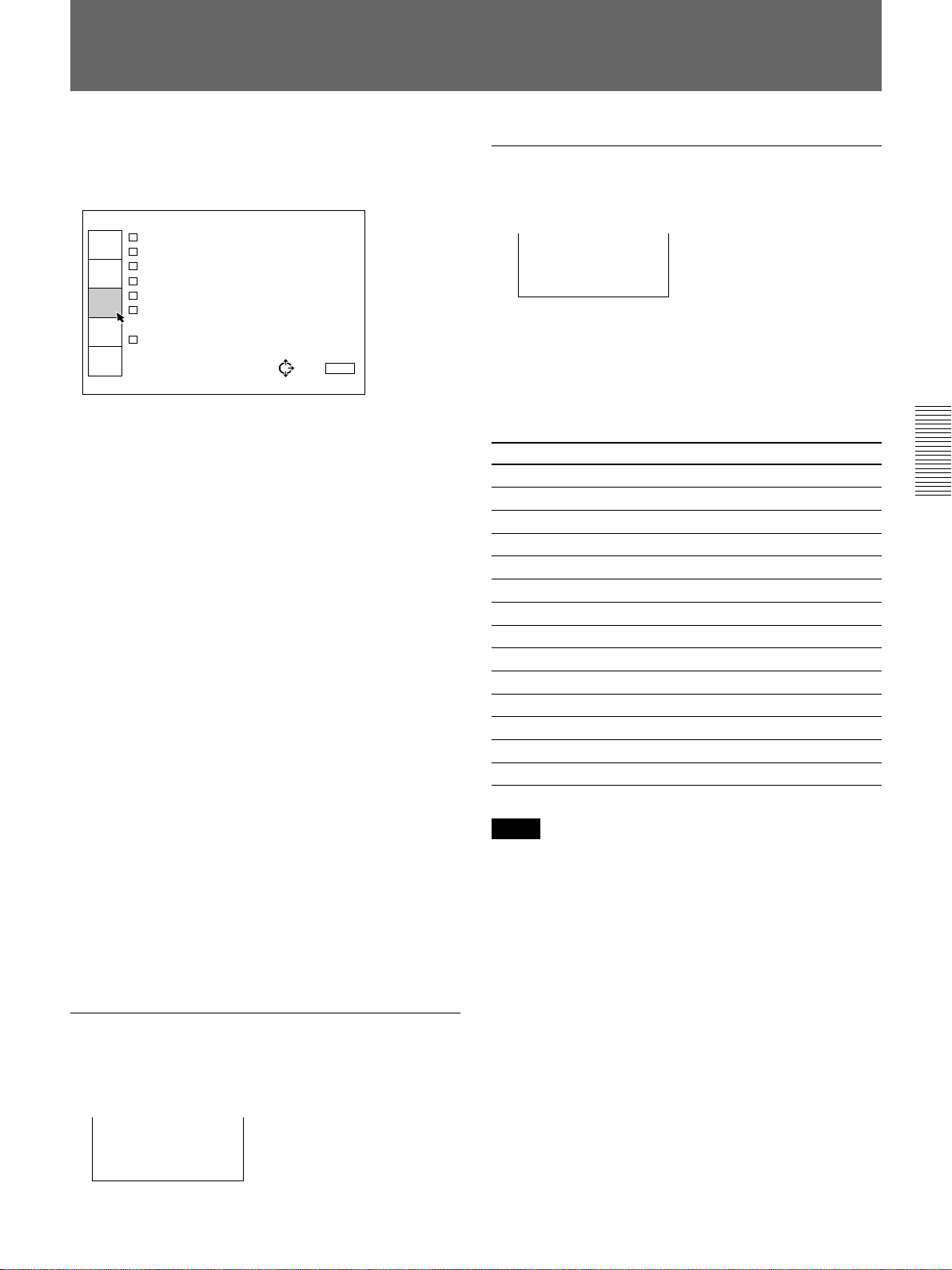
Using the MENU
Adjustments and settings using the menu
The projector is equipped with an on-screen menu for
making various adjustments and settings.
To select the language used in the menu, see page
27 (EN).
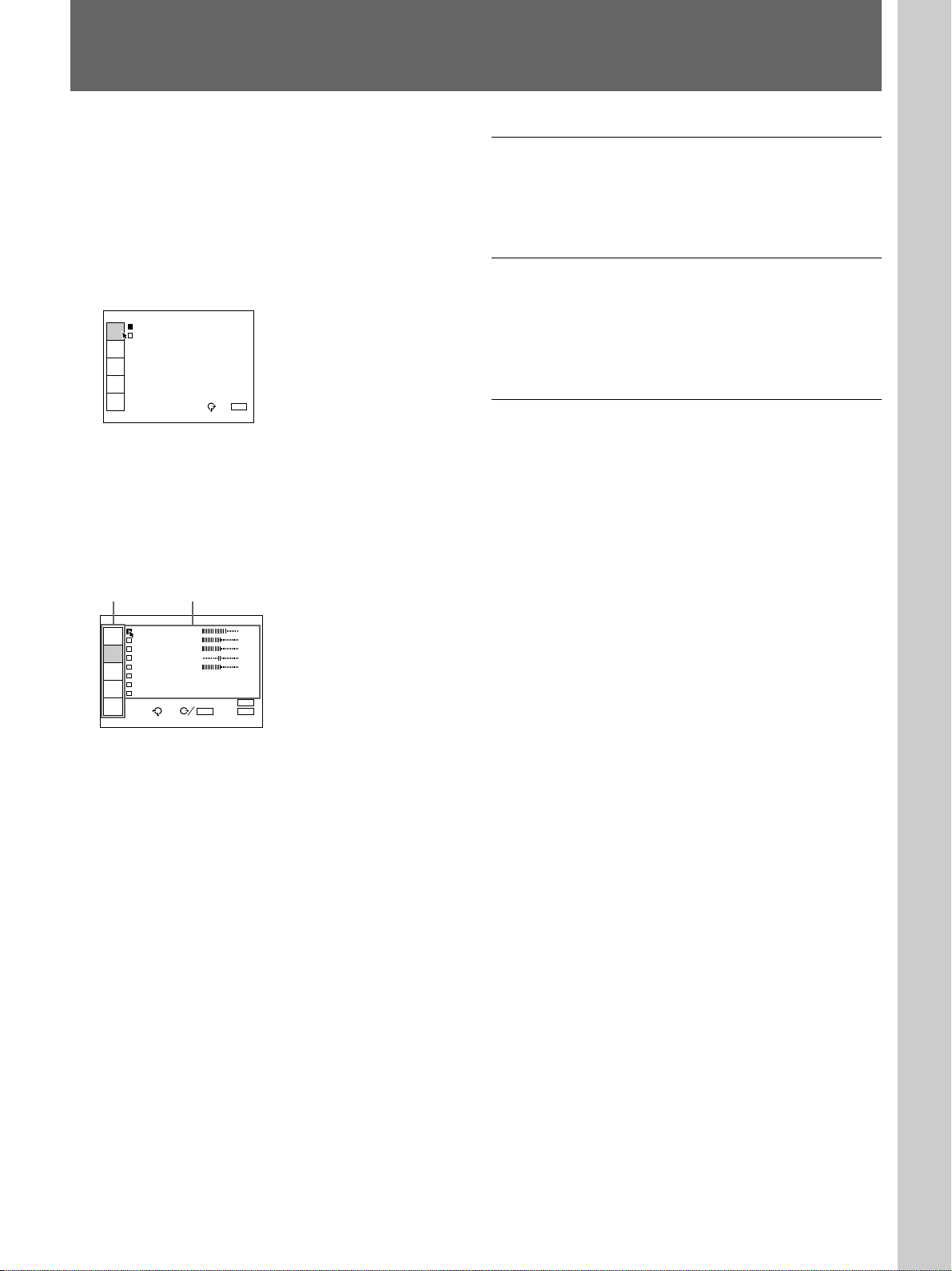
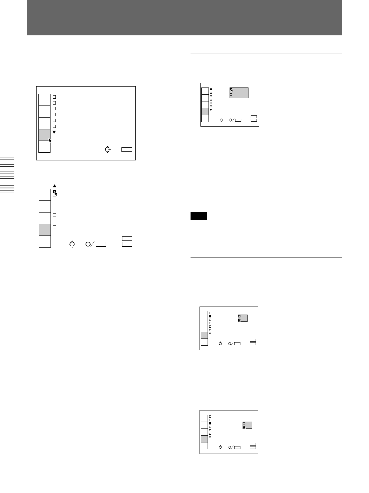
1 Press the MENU key.
The menu display appears.
The menu presently selected is highlighted in blue.
VIDEO
VIDEO
INPUT
SELECT
INPUT-A
PICTURE
CTRL
INPUT
SETTING
SET
SETTING
INPUT
INFO.
SEL: EXIT: MENU
2 Use the V or v keys on the control panel to select a
menu, then press the b or the ENTER key. On the
Remote Commander, move the joy stick up or
down to select a menu, then move it to the right or
press the ENTER key.
The selected menu appears.
Menus Setting items
To clear the menu display
Press the MENU key. The menu display disappears
automatically if no key is pressed for one minute.
To reset items that have been adjusted
Press the RESET key. “Reset complete!” appears on
the screen and the settings appearing on the screen will
be reset to their factory preset values.
About the memory of the settings
The settings other than the INPUT SETTING menu
are automatically stored in the projector memory.
Adjustments made in the INPUT SETTING menu
have to be saved with the SAVE TO MEMORY item
in the INPUT SETTING menu.
VIDEO
CONTRAST 80
INPUT
SELECT
BRIGHT 50
COLOR 50
PICTURE
CTRL
HUE 50
SHARP 50
INPUT
SETTING
D.PICTURE:OFF
COLOR SYS:AUTO
SET
SETTING
GAMMA MODE:
INPUT
INFO.
SEL:
SET: ENTER
RESET: RESET
EXIT: MENU
3 Make setting or adjustment on an item.
For details on setting individual items, see the relevant
menu pages.
19 (EN)
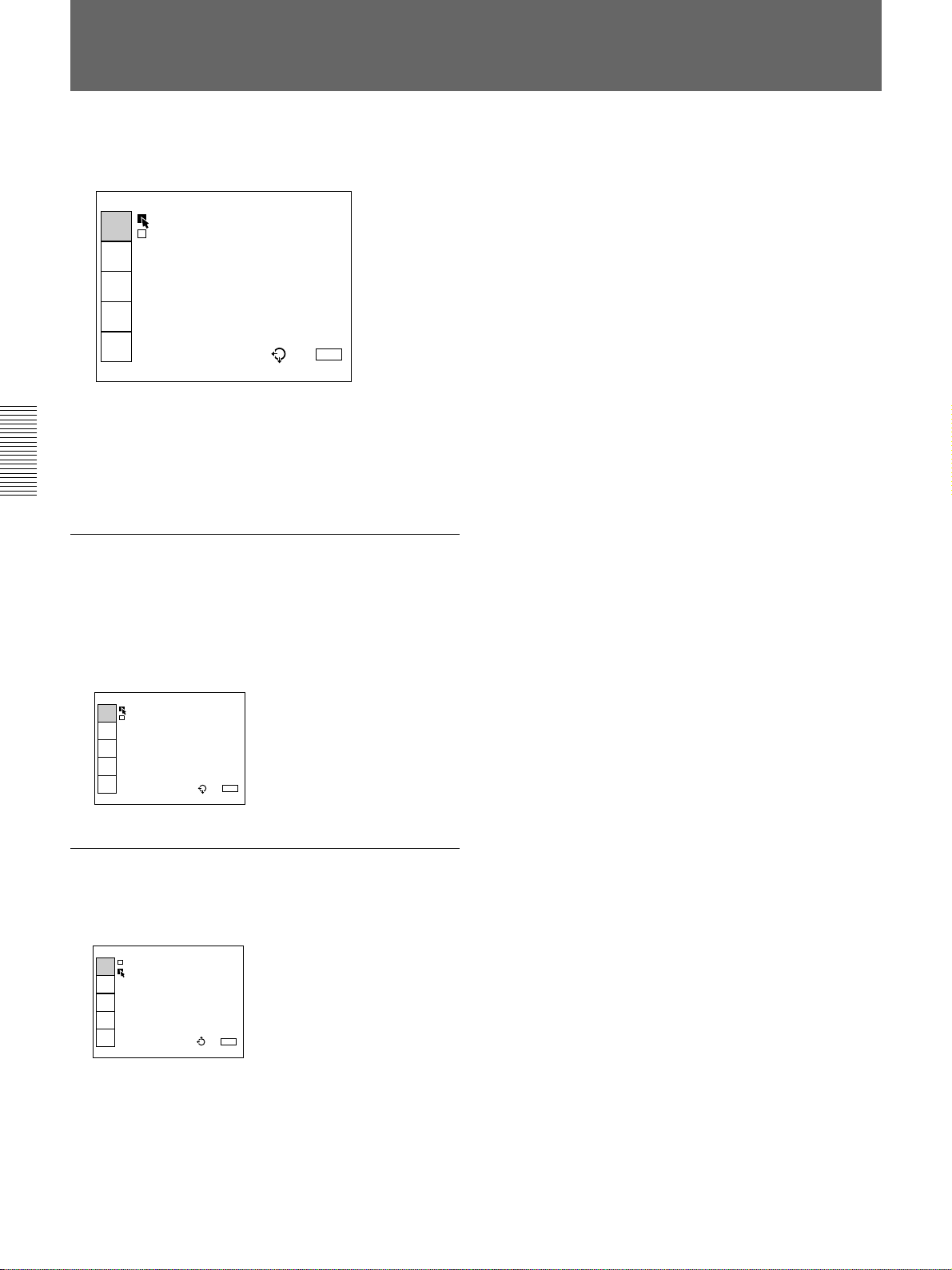
The INPUT SELECT Menu
The INPUT SELECT menu is used for selecting the
input signal.
VIDEO
VIDEO
INPUT
SELECT
INPUT-A
PICTURE
CTRL
INPUT
SETTING
SET
SETTING
INPUT
INFO.
Operation
Use the V or the v key on the control panel to select
the input, then press B key.
On the Remote Commander, move the joy stick up or
down to select the input, then move it to the left.
SEL: EXIT: MENU
VIDEO
Selects signal input from the VIDEO IN (S VIDEO or
VIDEO) connectors and the AUDIO IN L/R jacks. If
you have equipment connected to both the VIDEO and
the S VIDEO connectors, the S VIDEO will be
selected.
VIDEO
VIDEO
INPUT
SELECT
INPUT-A
PICTURE
CTRL
INPUT
SETTING
SET
SETTING
INPUT
INFO.
SEL: EXIT: MENU
INPUT-A
Selects the audio and video signals input from the
INPUT A connectors.
INPUT-A
VIDEO
INPUT
SELECT
INPUT-A
PICTURE
CTRL
INPUT
SETTING
SET
SETTING
INPUT
INFO.
SEL: EXIT: MENU
20 (EN)
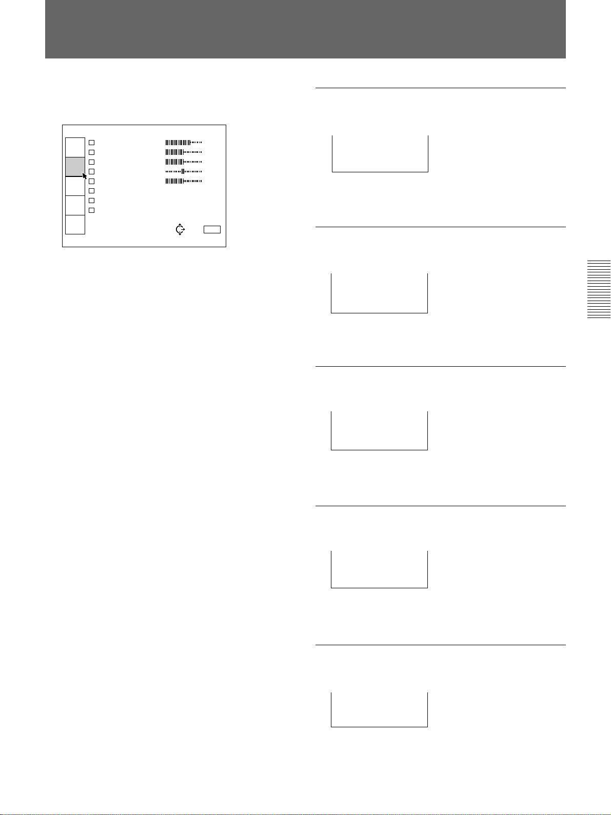
The PICTURE CTRL Menu
The PICTURE CTRL menu is used for adjusting the
picture. Adjustable items are displayed in green.
VIDEO
CONTRAST 80
INPUT
SELECT
BRIGHT 50
COLOR 50
PICTURE
CTRL
HUE 50
SHARP 50
INPUT
SETTING
D.PICTURE:OFF
COLOR SYS:AUTO
SET
SETTING
GAMMA MODE:
INPUT
INFO.
SEL: EXIT: MENU
Operation
1. Select an item
Use the V or the v key on the control panel to select
the item, then press the b or the ENTER key.
On the Remote Commander, move the joy stick up or
down to select the item, then move it to the right or
press the ENTER key.
2. Adjust an item
• When changing the adjustment level:
To increase the number, press the V or the b key.
On the Remote Commander, move the joy stick up
or to the right.
To decrease the number, press the v or the B key.
On the Remote Commander, move the joy stick
down or to the left.
Press the ENTER key to restore the original screen.
CONTRAST
Adjusts the picture contrast.
CONTRAST:80
The higher the setting, the greater the contrast.
The lower the setting, the lower the contrast.
BRIGHT
Adjusts the picture brightness.
BRIGHT:50
The higher the setting, the brighter the picture.
The lower the setting, the darker the picture.
COLOR
Adjusts color intensity.
COLOR:50
The higher the setting, the greater the intensity.
The lower the setting, the lower the intensity.
• When changing the setting:
Press the V or the v key on the control panel to
change the setting.
On the Remote Commander, move the joy stick up
or down to change the setting.
To restore the original screen, press the ENTER or
the B key.
On the Remote Commander, move the joy stick to
the left.
HUE
Adjusts skin tones.
HUE:50
A higher the setting, the picture becomes greenish.
A lower the setting, the picture becomes purplish.
SHARP
Adjusts the picture sharpness.
SHARP:50
The higher the setting, the sharper the picture.
The lower the setting, the softer the picture.
21 (EN)
The PICTURE CTRL Menu
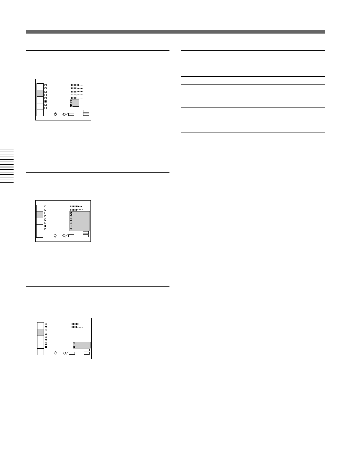
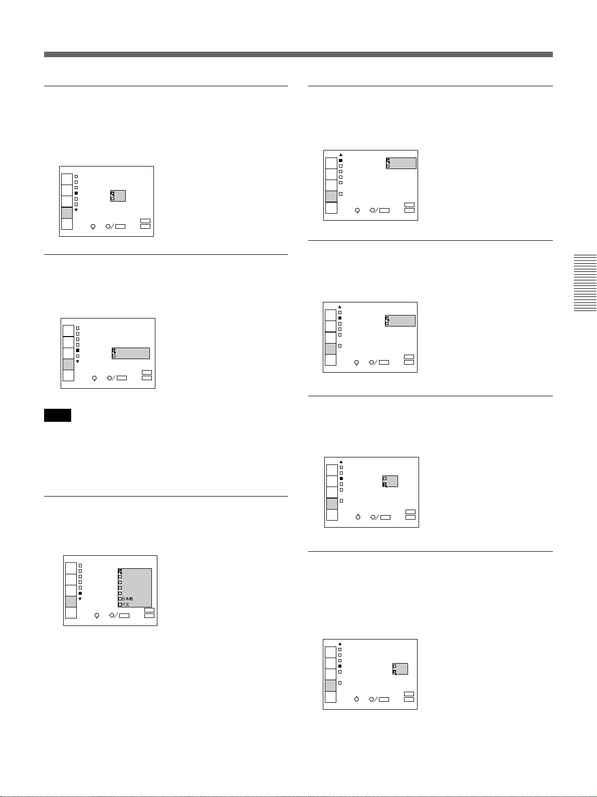
D. (Dynamic) PICTURE
Emphasizes the black color.
VIDEO
CONTRAST 80
INPUT
SELECT
BRIGHT 50
COLOR 50
PICTURE
CTRL
HUE 50
SHARP 50
INPUT
SETTING
D.PICTURE: ON
COLOR SYS: OFF
SET
SETTING
GAMMA MODE:
INPUT
INFO.
SEL:
SET: ENTER
RESET: RESET
EXIT: MENU
ON: Emphasizes the black color to produce a bolder
“dynamic” picture.
OFF: Reproduces the dark portions of the picture
accurately, in accordance with the source signal.
COLOR SYS (System)
Selects the color system of the input signal.
VIDEO
CONTRAST 80
INPUT
SELECT
BRIGHT 50
COLOR AUTO
PICTURE
CTRL
HUE NTSC3.58
SHARP PAL
INPUT
SETTING
D.PICTURE: SECAM
COLOR SYS: NTSC4.43
SET
SETTING
GAMMA MODE PAL-M
INPUT
INFO.
SEL:
SET: ENTER
RESET: RESET
EXIT: MENU
Items cannot be adjusted depending on
the types of input signal
Item Cannot be adjusted with
COLOR Signal input from INPUT A connectors,
HUE Input signal other than NTSC 3.58/4.43
SHARP RGB signal
D. PICTURE RGB signal
COLOR SYS Signal input from INPUT A connectors
GAMMA MODE
black-and-white signal
Signal input from VIDEO IN connectors,
component signal input from INPUT A
connectors.
Normally, set to AUTO.
If the picture is distorted or colorless, select the color
system according to the input signal.
GAMMA MODE
Selects a gamma correction curve.
INPUT-A
CONTRAST 80
INPUT
SELECT
BRIGHT 50
COLOR
PICTURE
CTRL
HUE
SHARP
INPUT
SETTING
D.PICTURE:OFF
COLOR SYS:A
SET
SETTING
GAMMA MODE: TEXT
INPUT
INFO.
SEL:
GRAPHICS: Improves the reproduction of half
tones. Photos can be reproduced in natural tones.
TEXT: Contrasts black and white. Suitable for
images that contains lots of text.
SET: ENTER
GRAPHICS
RESET: RESET
EXIT: MENU
22 (EN)
The INPUT SETTING Menu
The INPUT SETTING menu is used to adjust the input
signal. Adjustable items are displayed in green.
INPUT-A
DOT PHASE: 10
INPUT
SELECT
SIZE H:1056
SHIFT H:191 V: 20
PICTURE
CTRL
FILTER:OFF
CLAMP:AUTO
INPUT
SETTING
COLOR TEMP:HBM
SET
SETTING
SAVE TO MEMORY
INPUT
INFO.
SEL: EXIT: MENU
Operation
1. Select an item
Use the V or v key on the control panel to select the
item, then press the b or the ENTER key.
On the Remote Commander, move the joy stick up or
down to select the item, then move it to the right or
press the ENTER key.
2. Adjust an item
• When changing the adjustment level:
To increase the number, press the V or the b key.
On the Remote Commander, move the joy stick up
or to the right.
To decrease the number, press the v or the B key.
On the Remote Commander, move the joy stick
down or to the left.
Press the ENTER key to restore the original screen.
SIZE
Adjusts the horizontal size of pictures input from
INPUT A.
SIZE H:1056
The higher the setting, the larger the horizontal size of
the picture.
The lower the setting, the smaller the horizontal size of
the picture. Adjust the setting according to the
horizontal dots of the input signal.
Input signal Setting
VGA1) mode3 (640×480 dots) 800
2)
VESA
72 Hz (640×480 dots) 832
Macintosh13-inch mode (separate sync) 864
Macintosh16-inch mode 1152
VGA mode1 (640×350 dots) 800
VGA mode2 (640×400 dots) 800
VESA 75 Hz (640×480 dots) 840
S VGA VESA 56 Hz (800×600 dots) 1024
S VGA VESA 60 Hz (800×600 dots) 1056
S VGA VESA 72 Hz (800×600 dots) 1040
S VGA VESA 75Hz (800×600 dots) 1056
S VGA VESA 85 Hz (800×600 dots) 1048
XGA VESA 60 Hz (1024×768 dots) 1076
XGA VESA 72 Hz (1024×768 dots) 1063
• When changing the setting:
Press the V or the v key to change the setting.
On the Remote Commander, move the joy stick up
or down to change the setting.
To restore the original screen, press the ENTER or
the B key.
Notes
•When a resolution of a signal input from the INPUT
A connectors is less than 832 (horizontal) × 624
(vertical) dots, areas around the pictures are displayed
in black.
•Compressed XGA signal is reproduced.
On the Remote Commander, move the joy stick to
the left.
DOT PHASE
Adjusts the dot phase of the LCD panel and the signal
input from INPUT A.
DOT PHASE: 10
.........................................................................................................................................................................................................
1) VGA is a registered trademark of International Business Machines Corporation, U.S.A.
2) VESA is a registered trademark of Video Electronics Standard Association.
23 (EN)
The INPUT SETTING Menu
SHIFT
Adjusts the position of the picture input from INPUT
A.
SHIFT H:191 V: 20
H adjusts the horizontal position of the picture.
V adjusts the vertical position of the picture.
As the setting for H increases, the picture moves to the
right, and as the setting decreases, the picture moves to
the left.
As the setting for V increases, the picture moves up,
and as the setting decreases, the picture moves down.
Use the B or the b key to adjust the horizontal position
and the V and v key for the vertical position.
FILTER
Corrects the vertical bands that appear on the picture
input from INPUT A.
INPUT-A
DOT PHASE: 10
INPUT
SELECT
SIZE H:1056
SHIFT H:191 V: 20
PICTURE
CTRL
FILTER: ON
CLAMP:A OFF
INPUT
SETTING
COLOR TEMP:HBM
SET
SETTING
SAVE TO MEMORY
INPUT
INFO.
SEL: SET: ENTER
The vertical bands may occur when an RGB signal
which horizontal resolution is other than 640 dots is
input. In such cases, set to ON. The picture will loose
some clarity, but the vertical bands will be reduced.
Set to OFF to associate a dot of the input signal with a
pixel of the LCD.
RESET: RESET
EXIT: MENU
CLAMP
Corrects the luminance of the picture input from
INPUT A.
INPUT-A
DOT PHASE: 10
INPUT
SELECT
SIZE H:1056
SHIFT H:191 V: 20
PICTURE
CTRL
FILTER:OFF
CLAMP: AUTO
INPUT
SETTING
COLOR SonGHBM
H/C
SET
SETTING
SAVE TO MEMORY
INPUT
INFO.
SEL: SET: ENTER
RESET: RESET
EXIT: MENU
CLAMP is used as a standard for setting the black
level of a picture correctly. The standard position of
the clamp depends on the kind of sync. signal being
used. Normally, the projector CPU judges the signal
and sets the position automatically. However, the CPU
can misjudge the signal because of noise. If the
luminance of the picture seems to be incorrect (too
dark, the black color is too light, or the luminance is
unstable) the clamp position may need to be changed.
AUTO: Automatic setting mode. Normally set to this
position.
SonG: Set to this position if the black seems too light
or greenish.
H/C: Set to this position if the picture is too dark or
luminance is unstable.
Note
If the luminance is still incorrect after changing the
clamp setting, check the input signal and the
connections.
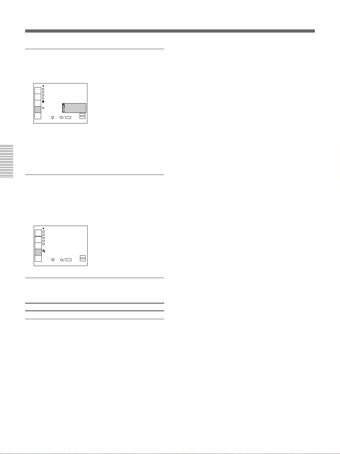
COLOR TEMP
24 (EN)
Adjusts the color temperature.
INPUT-A
DOT PHASE: 10
INPUT
SELECT
SIZE H:1056
SHIFT H:191 V: 20
PICTURE
CTRL
FILTER:OFF
CLAMP:AUTO
INPUT
SETTING
COLOR TEMP: HIGH
LOW
SET
SETTING
SAVE TO MEM HBM
INPUT
INFO.
SEL: SET: ENTER
RESET: RESET
EXIT: MENU
HIGH: Makes the white color bluish.
LOW: Makes the white color reddish.
HBM (High Brightness Mode): Reproduces a
picture with high brightness.
SAVE TO MEMORY
You can save the settings in the INPUT SETTING
menu in the projector memory. Whenever a new
setting is saved, the previous settings are overwritten.
INPUT-A
DOT PHASE: 10
INPUT
SELECT
SIZE H:1056
SHIFT H:191 V: 20
PICTURE
CTRL
FILTER:OFF
CLAMP:AUTO
INPUT
SETTING
COLOR TEMP:HBM
SET
SETTING
SAVE TO MEMORY
INPUT
INFO.
SEL: SET: ENTER
Once you have adjusted the settings, select SAVE TO
MEMORY and press the ENTER or the b key. When
the settings have been saved, the message “Saving is
complete!” appears.
INPUT-A
DOT PHASE: 10
INPUT
SELECT
SIZE H:1056
SHIFT H:191 V: 20
PICTURE
CTRL
FILTER:OFF
CLAMP:AUTO
INPUT
SETTING
COLOR TEMP:HBM
SET
SETTING
SAVE TO MEMORY
INPUT
INFO.
SEL: SET: ENTER
Saving is complete!
RESET: RESET
EXIT: MENU
RESET: RESET
EXIT: MENU
Items cannot be adjusted depending on
the types of input signal
Item Cannot be adjusted with
DOT PHASE Signal input from VIDEO IN connectors
SIZE Signal input from VIDEO IN connectors
FILTER Signal input from VIDEO IN connectors,
component input signal, 15k RGB signal
CLAMP Signal input from VIDEO IN connectors,
component input signal, 15k RGB signal
SHIFT Signal input from VIDEO IN connectors
25 (EN)
The SET SETTING Menu
The SET SETTING menu is used for changing the
settings of the projector. Adjustable items are
displayed in green.
<page 1>
INPUT-A
STATUS:ON
INPUT
SELECT
PIC.MUTING:OFF
AUDIO MUTING:OFF
PICTURE
CTRL
SPEAKER:ON
INPUT-A:RGB
INPUT
SETTING
LANGUAGE:ENGLISH
SET
SETTING
INPUT
INFO.
SEL: EXIT: MENU
<page 2>
INPUT-A
H POLARITY:NORMAL
INPUT
SELECT
V POLARITY:NORMAL
HALF TONE:OFF
PICTURE
CTRL
POWER SAVING:OFF
SIRCS RECEIVER:
INPUT
SETTING
FRONT&REAR
PATTERN
SET
SETTING
INPUT
INFO.
SEL:
SET: ENTER
RESET: RESET
EXIT: MENU
STATUS (on-screen display)
Sets up the on-screen display.
INPUT-A
STATUS: ON
INPUT
SELECT
PIC.MUT OFF
AUDIO M ALL OFFF
PICTURE
CTRL
SPEAKER:ON
INPUT-A:RGB
INPUT
SETTING
LANGUAGE:ENGLISH
SET
SETTING
INPUT
INFO.
SEL: SET: ENTER
ON: Shows all of the on-screen displays.
OFF: Turns off the on-screen displays except for the
menus, “NO INPUT”, “PIC/AUDIO MUTING”, a
message when turning off the power, and warning
messages.
ALL OFF: Turns off all of the on-screen displays
except for the menus, a message when turning off
the power, and warning messages.
Note
When you set STATUS to ALL OFF, the displays for
changing the adjustment level (which are displayed on
one line at the bottom) are not displayed.
RESET: RESET
EXIT: MENU
The SET SETTING menu consists of two pages.
To change the page, press the v or V the key until the
page changes when selecting an item.
On the Remote Commander, move the joy stick up or
down until the page changes when selecting an item.
Operation
1. Select an item
Use the V or the v key on the control panel to select
the item, then press the b or the ENTER key.
On the Remote Commander, move the joy stick up or
down to select the item, then move it to the right or
press the ENTER key.
2. Change the setting
Press the V or the v key to change the setting.
On the Remote Commander, move the joy stick up or
down to change the setting.
To restore the original screen, press the ENTER or the
B key.
On the Remote Commander, move the joy stick to the
left.
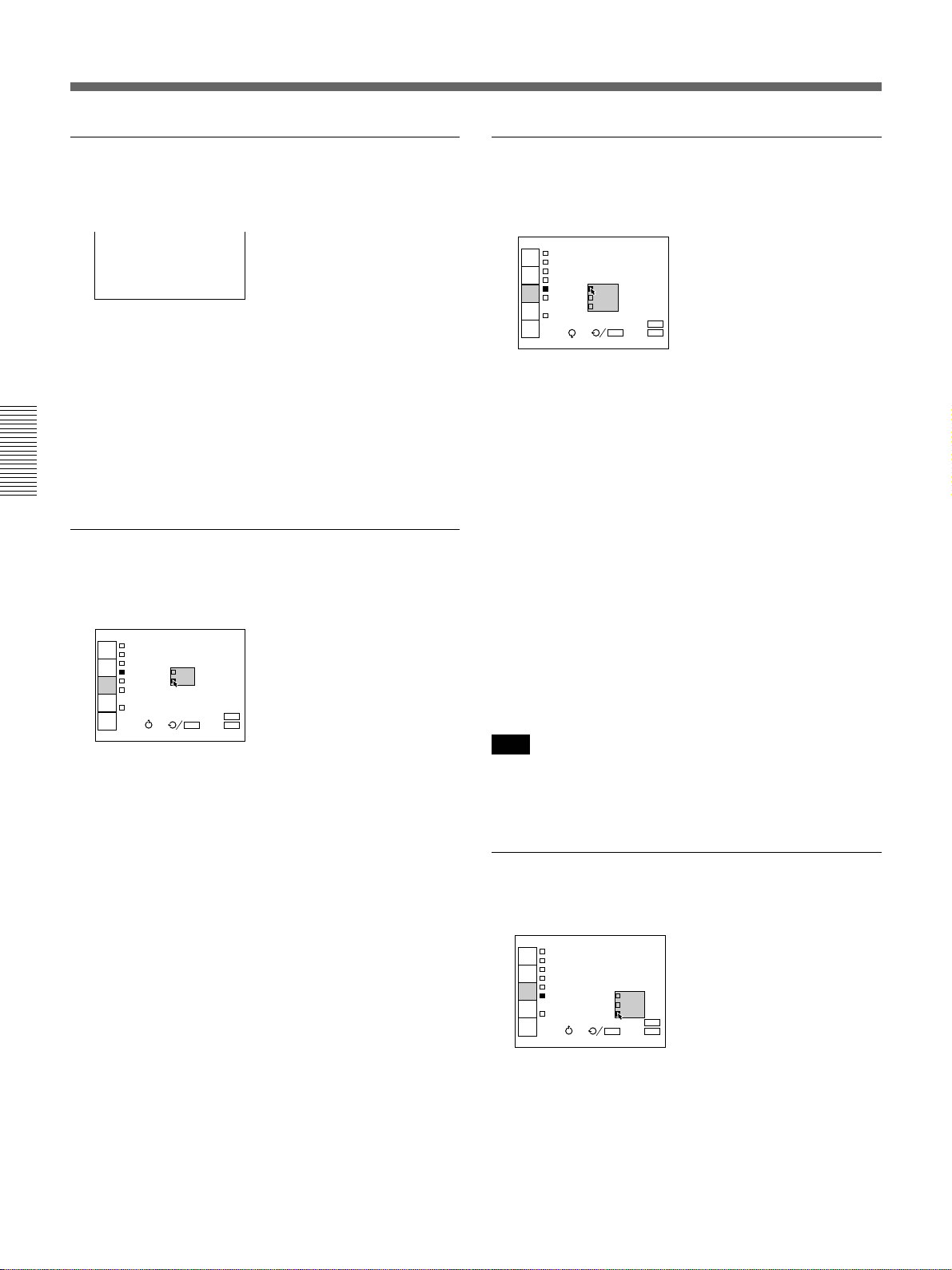
PIC. MUTING
Set to ON to cut off the picture.
When set to ON, “PIC MUTING” appears on the
screen.
INPUT-A
STATUS:ON
INPUT
SELECT
PIC.MUTING: ON
AUDIO MUTIN OFFF
PICTURE
CTRL
SPEAKER:ON
INPUT-A:RGB
INPUT
SETTING
LANGUAGE:ENGLISH
SET
SETTING
INPUT
INFO.
SEL: SET: ENTER
RESET: RESET
EXIT: MENU
AUDIO MUTING
Set to ON to cut off the sound.
When set to ON, “AUDIO MUTING” appears on the
screen.
INPUT-A
STATUS:ON
INPUT
SELECT
PIC.MUTING:OFF
AUDIO MUTING: ON
PICTURE
CTRL
SPEAKER:ON OFF
INPUT-A:RGB
INPUT
SETTING
LANGUAGE:ENGLISH
SET
SETTING
INPUT
INFO.
SEL: SET: ENTER
RESET: RESET
EXIT: MENU
26 (EN)
SPEAKER
H (Horizontal) POLARITY
Set to OFF to cut off the sound of the internal
speakers. When set to OFF, “SPEAKER OFF” appears
on the screen when you turn on the power.
INPUT-A
STATUS:ON
INPUT
SELECT
PIC.MUTING:OFF
AUDIO MUTING:OFF
PICTURE
CTRL
SPEAKER: ON
INPUT-A: OFF
INPUT
SETTING
LANGUAGE:ENGLISH
SET
SETTING
INPUT
INFO.
SEL: SET: ENTER
RESET: RESET
EXIT: MENU
INPUT-A
Selects the RGB or COMPONENT signal input from
INPUT A.
INPUT-A
STATUS:ON
INPUT
SELECT
PIC.MUTING:OFF
AUDIO MUTING:OFF
PICTURE
CTRL
SPEAKER:ON
INPUT-A: RGB
INPUT
SETTING
LANGUAGE COMPONENT
SET
SETTING
INPUT
INFO.
SEL: SET: ENTER
RESET: RESET
EXIT: MENU
Note
If the setting is not correct, “Please check INPUT-A in
the SET SETTING.” appears on the screen and the
color of the picture becomes strange or the picture is
not displayed.
LANGUAGE
Selects the language used in the menu and on screen
displays.
INPUT-A
STATUS:ON
INPUT
SELECT
PIC.MUTIN ENGLISH
AUDIO MUT FRANCAIS
PICTURE
CTRL
SPEAKER:O DEUTSCH
INPUT-A:R ITALIANO
INPUT
SETTING
LANGUAGE: ESPANOL
SET
SETTING
INPUT
INFO.
SEL: SET: ENTER
Available languages are: English, French, German,
Italian, Spanish, Japanese and Chinese.
RESET: RESET
EXIT: MENU
Set to REVERSE to reverse the horizontal orientation
of the picture.
INPUT-A
H POLARITY: NORMAL
INPUT
SELECT
V POLARITY: REVERSE
HALF TONE:OFF
PICTURE
CTRL
POWER SAVING:OFF
SIRCS RECEIVER:
INPUT
SETTING
FRONT&REAR
PATTERN
SET
SETTING
INPUT
INFO.
SEL: SET: ENTER
RESET: RESET
EXIT: MENU
V (vertical) POLARITY
Set to REVERSE to reverse the vertical orientation of
the picture.
INPUT-A
H POLARITY:NORMAL
INPUT
SELECT
V POLARITY: NORMAL
HALF TONE:O REVERSE
PICTURE
CTRL
POWER SAVING:OFF
SIRCS RECEIVER:
INPUT
SETTING
FRONT&REAR
PATTERN
SET
SETTING
INPUT
INFO.
SEL: SET: ENTER
RESET: RESET
EXIT: MENU
HALF TONE
Set to ON to reduce the luminance of the menu
background.
INPUT-A
H POLARITY:NORMAL
INPUT
SELECT
V POLARITY:NORMAL
HALF TONE: ON
PICTURE
CTRL
POWER SAVI OFFFF
SIRCS RECEIVER:
INPUT
SETTING
FRONT&REAR
PATTERN
SET
SETTING
INPUT
INFO.
SEL: SET: ENTER
RESET: RESET
EXIT: MENU
POWER SAVING
When set to ON, the projector goes into the power
saving mode if no signal is input for 10 minutes. The
power saving mode is canceled when a signal is input
or whenever a key is pressed.
INPUT-A
H POLARITY:NORMAL
INPUT
SELECT
V POLARITY:NORMAL
HALF TONE:OFF
PICTURE
CTRL
POWER SAVING: ON
SIRCS RECEIVE OFF
INPUT
SETTING
FRONT&REAR
PATTERN
SET
SETTING
INPUT
INFO.
SEL: SET: ENTER
RESET: RESET
EXIT: MENU
(Continued)
27 (EN)
The SET SETTING Menu
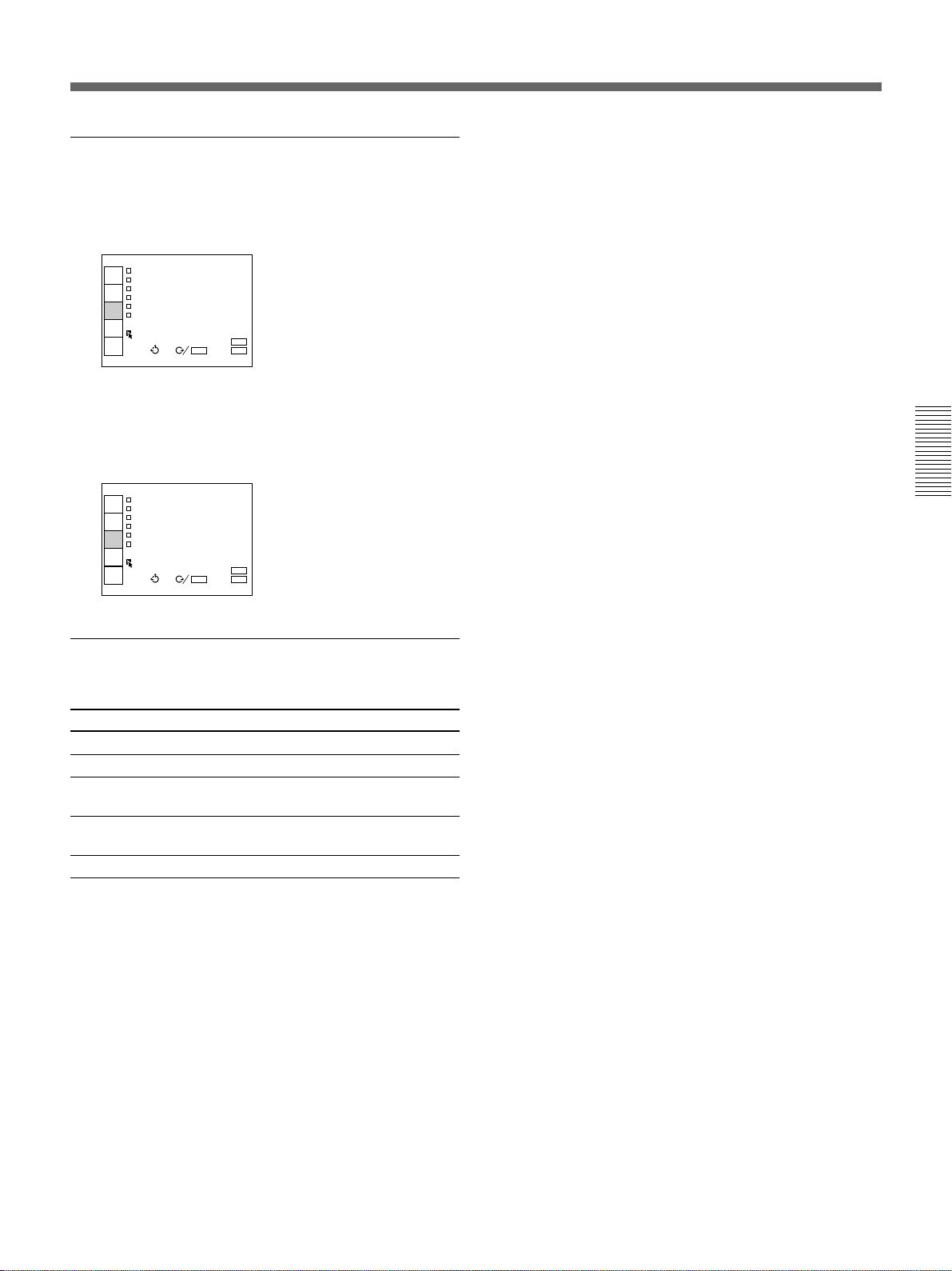
SIRCS RECEIVER
Selects the remote control detectors on the front and
rear of the projector.
INPUT-A
H POLARITY:NORMAL
INPUT
SELECT
V POLARITY:NORMAL
HALF TONE:OFF
PICTURE
CTRL
POWER SAVING:OFF
SIRCS RECEIVER:
INPUT
SETTING
FRONT&REAR
PATTERN FRONT
SET
SETTING
REAR
INPUT
INFO.
SEL: SET: ENTER
FRONT & REAR: Activates both the front and rear
detectors.
FRONT: Activates the front detector only.
REAR: Activates the rear detector only.
PATTERN
RESET: RESET
EXIT: MENU
Press the b or the ENTER key to display the H test
pattern. Press the B or the ENTER key to clear the
pattern. The pattern disappears automatically if no key
is pressed for one minute.
INPUT-A
H POLARITY:NORMAL
INPUT
SELECT
V POLARITY:NORMAL
HALF TONE:OFF
PICTURE
CTRL
POWER SAVING:OFF
SIRCS RECEIVER:
INPUT
SETTING
FRONT&REAR
PATTERN
SET
SETTING
INPUT
INFO.
SEL: SET: ENTER
RESET: RESET
EXIT: MENU
Item cannot be adjusted depending on the
types of input signal
Item Cannot be adjusted with
INPUT-A Signal input from VIDEO IN connectors
28 (EN)
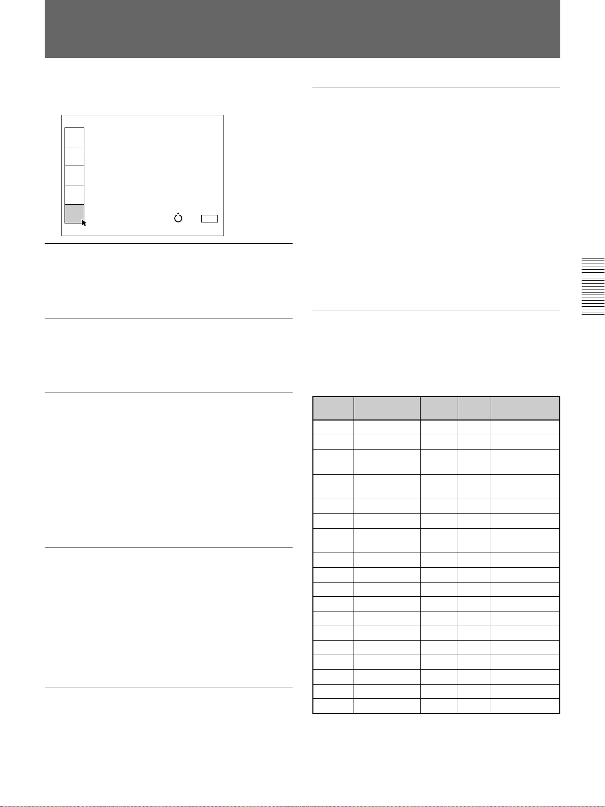
The INPUT INFO Menu
The INPUT INFO menu displays the information on a
current input signal.
INPUT-A
fH:37.9kHz
INPUT
SELECT
fV:60.3Hz
H/C SYNC:POS
PICTURE
CTRL
V-SYNC:POS
SonG:---
INPUT
SETTING
INPUT SIGNAL:RGB
SET
SETTING
INPUT MEMORY No.15
INPUT
INFO.
SEL: EXIT: MENU
fH (Horizontal frequency)
Indicates the horizontal frequency of the input signal.
This indication is only used as a reference, this is not
absolute value.
fV (Vertical frequency)
Indicates the vertical frequency of the input signal.
This indication is only used as a reference, this is not
absolute value.
H/C (Horizontal/Composite)-SYNC
Indicates the polarity of the horizontal or the
composite sync. signal. When the picture is being
projected using its sync signal, POS (NEG) is
displayed in green. When the picture is being projected
without using sync signal, POS (NEG) is displayed in
white.
POS: The polarity of the sync. signal is positive.
NEG: The polarity of the sync. signal is negative.
---: No sync. signal is input.
V(Vertical) SYNC
Indicates the polarity of the vertical sync. signal. When
the picture is being projected using its sync signal,
POS (NEG) is displayed in green. When the picture is
being projected without using sync signal, POS (NEG)
is displayed in white.
POS: The polarity of the sync. signal is positive.
NEG: The polarity of the sync. signal is negative.
---: No sync. signal is input.
SonG
Indicates the polarity of the Sync on Green. When the
picture is being projected using its sync signal, NEG is
displayed in green. When the picture is being projected
without using sync signal, NEG is displayed in white.
NEG: The polarity of the sync. signal is negative.
---: No Sync. signal is input.
INPUT SIGNAL
Displays the type of current input signal.
NTSC 3.58: NTSC 3.58 input signal from VIDEO IN
NTSC 4.43: NTSC 4.43 input signal from VIDEO IN
PAL: PAL input signal from VIDEO IN
SECAM: SECAM input signal from VIDEO IN
PAL-M: PAL-M input signal form VIDEO IN
S-VIDEO: S-VIDEO input signal from VIDEO IN
RGB: RGB input signal
COMPONENT: Component input signal
B/W 50: Black and white input signal from VIDEO
IN (vertical frequency: 50 Hz)
B/W 60: Black and white input signal from VIDEO
IN (vertical frequency: 60 Hz)
INPUT MEMORY No.
Indicates the memory number of the INPUT SETTING
data used for current input signal.
Each preset signal is stored in following memory
number.
Memory Preset signal fH(kHz) fV(Hz) Sync
No.
01 Video (60 Hz) – – –
02 Video (50 Hz) – – –
03
04
05 VGA mode3 31.5 59.9 H-neg V-neg
06 VESA 72Hz 37.9 72.8 H-neg V-pos
07 Macintosh 13” 35.0 66.7 H-neg V-neg
08 Macintosh 16” 49.7 74.6 H-neg V-neg
09 VGA mode1 31.5 70.1 H-pos V-neg
10 VGA mode2 31.5 70.1 H-neg V-pos
12 VESA 75 Hz 37.5 75.0 H-neg V-neg
14 S VGA 56 Hz 35.2 56.3 H-neg V-neg
15 S VGA 60 Hz 37.9 60.3 H-pos V-pos
16 S VGA 72 Hz 48.1 72.2 H-pos V-pos
17 S VGA 75 Hz 46.9 75.0 H-pos V-pos
18 S VGA 85 Hz 53.7 85.1 H-pos V-pos
19
20
15k RGB /
Component(60 Hz)
15k RGB/
Component(50 Hz)
separate sync
XGA VESA 60 Hz
XGA VESA 70 Hz
––
––
48.4 60.0 H-neg V-neg
56.5 70.1 H-neg V-neg
Composite sync/
Sync on G
Composite sync/
Sync on G
When signals other than the preset signals are input
and adjusted in the INPUT SETTING menu, they are
stored in memory numbers 23 to 42.
29 (EN)
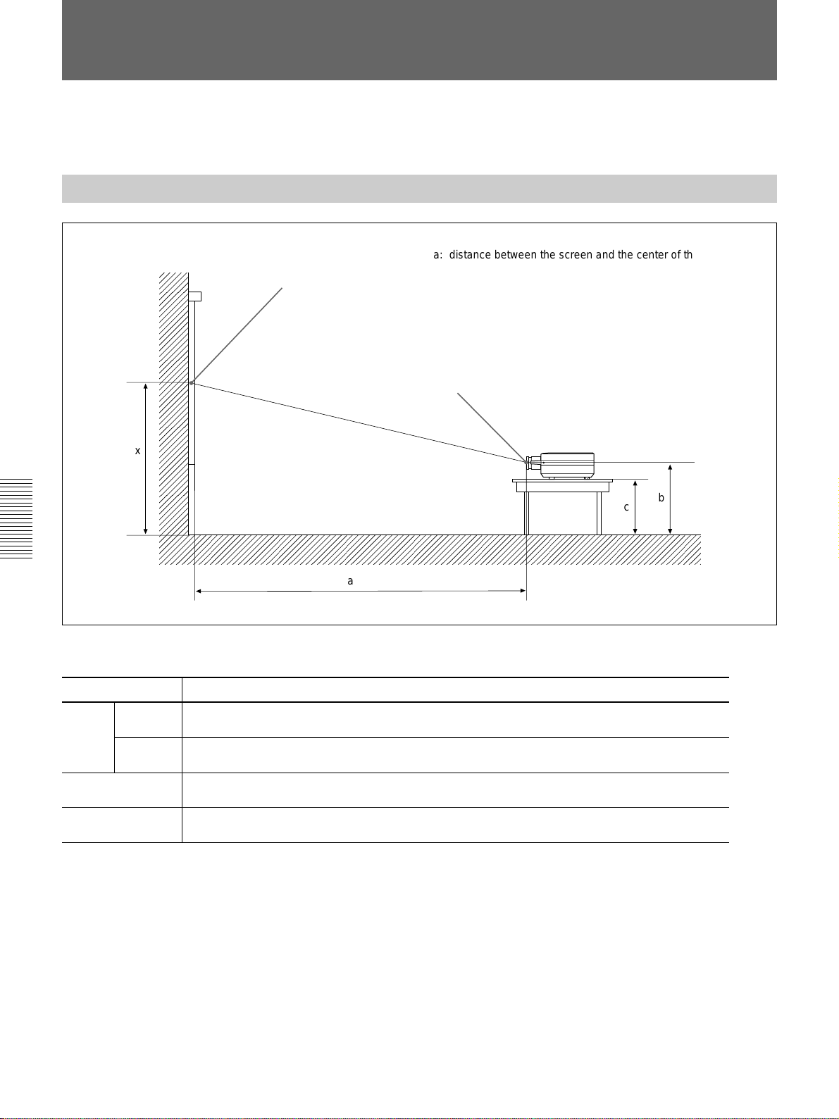
Installation Examples
The on-screen picture size changes according to the input signal. Note that
the projection distance also changes depending on the picture size.
Floor Installation
Wall
Center of the screen
x
a
a: distance between the screen and the center of the lens
b: distance from the floor to the center of the lens
c: distance from the floor to the foot of the projector
x: free
Center of the lens
b
c
Example: Installation measurement for Macintosh 16-inch mode signal input
Unit: mm (inches)
Screen size (inches) 40 60 80 100 120 150 180 200 250 300
Minimum
a
Maximum
b
c
1470 2260 3040 3820 4600 5770 6950 7730 9680 11640
(57 7/8) (89) (119 3/4) (150 1/2) (181 1/8) (227 1/4) (273 5/8) (304 3/8) (381 1/8) (458 3/8)
2190 3320 4450 5580 6720 8420 10120 11250 14080 16910
(86 1/4) (130 3/4) (175 1/4) (219 3/4) (264 5/8) (331 1/2) (398 1/2) (443) (554 3/8) (665 3/4)
x–336 x–504 x–672 x–840 x–1008 x–1260 x–1511 x–1679 x–2099 x–2519
(13 1/4) (19 7/8) (26 1/2) (33 1/8) (39 3/4) (49 5/8) (59 1/2) (66 1/8) (82 3/4) (99 1/4)
x–447 x–615 x–783 x–951 x–1119 x–1371 x–1622 x–1790 x–2210 x–2630
(17 5/8) (24 1/4) (30 7/8) (37 1/2) (44 1/8) (54) (63 7/8) (70 1/2) (87 1/8) (103 5/8)
Floor
To calculate the installation measurement (unit: mm)
SS: screen size diagonal (inches)
• Macintosh 16-inch mode signal input
a (minimum) = (SS × 49.958/1.31 – 86) × 1.025
a (maximum) = (SS × 78.110/1.31 – 82) × 0.975
b = x – (SS/1.31 × 11)
c = x – (SS/1.31 × 11+111)
• S VGA/video signal input
a (minimum) = (SS × 49.958/1.26 – 86) × 1.025
a (maximum) = (SS × 78.110/1.26 – 82) × 0.975
b = x – (SS/1.26 × 11)
c = x – (SS/1.26 × 11+111)
• XGA signal input
a (minimum) = (SS × 49.958/1.29 – 86) × 1.025
a (maximum) = (SS × 78.110/1.29 – 82) × 0.975
b = x – (SS/1.29 × 11)
c = x – (SS/1.29 × 11+111)
• VGA signal input
a (minimum) = (SS × 49.958 – 86) × 1.025
a (maximum) = (SS × 78.110 – 82) × 0.975
b = x – (SS × 11)
c = x – (SS × 11+111)
30 (EN)
 Loading...