

Sony VPL-S1800Q User Manual
VPD-S1800Q/S1800QM
Data P
Operating Instruct
Mode d’emploi
Manual de instruc
VPD-S18
VPD-S18
1997 by Sony Corporation
English
WARNING
To prevent fire or shock hazard, do not
expose the unit to rain or moisture.
To avoid electrical shock, do not open the
cabinet. Refer servicing to qualified
personnel only.
This symbol is intended to alert the
user to the presence of uninsulated
“dangerous voltage” within the
product’s enclosure that may be of
suffcient magnitude to constitute a risk
of electric shock to persons.
This symbol is intended to alert the
user to the presence of important
operating and maintenance (servicing)
instructions in the literature
accompanying the appliance.
For the customers in the USA
This equipment has been tested and found to comply with
the limits for a Class A digital device, pursuant to Part 15 of
the FCC Rules. These limits are designed to provide
reasonable protection against harmful interference when the
equipment is operated in a commercial environment. This
equipment generates, uses, and can radiate radio frequency
energy and, if not installed and used in accordance with the
instruction manual, may cause harmful interference to radio
communications. Operation of this equipment in a residential
area is likely to cause harmful interference in which case the
user will be required to correct the interference at his own
expense.
For the customers in the United Kingdom
WARNING
THIS APPARATUS MUST BE EARTHED
IMPORTANT
This wires in this mains lead are coloured in accordance with
the following code:
Green-and-Yellow: Earth
Blue: Neutral
Brown: Live
As the colours of the wires in the mains lead of this
apparatus may not correspond with the coloured markings
identifying the terminals in your plug proceed as follows:
The wire which is coloured green-and-yellow must be
connected to the terminal in the plug which is marked by the
letter E or by the safety earch symbol Y or coloured green or
green-and-yellow.
The wire which is coloured blue must be connected to the
terminal which is marked with the letter N or coloured black.
The wire which is coloured brown must be connected to the
terminal which is marked with the letter L or coloured red.
Voor de klanten in Nederland
• Dit apparaat bevat een Li-ion batterij voor memory back-
up.
• De IC3004/3011 van plaat Y is voorzien van een batterij
voor noodvoeding van het geheugen.
• Raadpleeg uw leverancier over de verwijdering van de
batterij op het moment dat u het apparaat bij einde
levensduur afdankt.
• Gooi de batterij niet weg, maar lever hem in als KCA.
• Bij dit produkt zijn batterijen geleverd.
Wanneer deze leeg zijn, moet u ze niet
weggooien maar inleveren als KCA.
The socket-outlet should be installed near the equipment
and be easily accessible.
You are cautioned that any changes or modifications not
expressly approved in this manual could void your authority
to operate this equipment.
For the customers in Canada
This Class A digital apparatus meets all requirements of the
Canadian Interference-Causing Equipment Regulations.
2 (EN)

Table of Contents
Overview
Projecting
Adjustments and Settings
Using the Menu
Precautions.........................................................................4
Features ..............................................................................6
Location and Function of Controls ..................................7
Projecting the Picture on the Screen .............................16
Using the Menu ................................................................19
The INPUT SELECT Menu ...............................................20
The PICTURE CTRL Menu ...............................................21
The INPUT SETTING Menu..............................................23
The SET SETTING Menu..................................................26
The INPUT INFO Menu .....................................................30
Installation/Connection
Examples
Maintenance
Others
Installation Examples ......................................................32
About the Installation of the Projector ............................ 32
Floor Installation ............................................................. 33
Ceiling Installation .......................................................... 35
Stack Installation............................................................. 37
Connection Examples......................................................42
Connecting a Computer or a VCR .................................. 42
Connecting 15k RGB/Component Equipment................ 43
Connecting the Switchers................................................ 44
Using Stacked Projectors ................................................ 45
Replacing the Lamp.........................................................48
Troubleshooting...............................................................49
Specifications...................................................................51
Index..................................................................................54
EN
English
3 (EN)

Precautions
On safety
Overview
On installation
•Check that the operating voltage of your unit is identical with the voltage
of your local power supply. If voltage adaptation is required, consult
qualified service personnel.
•Should any liquid or solid object fall into the cabinet, unplug the unit and
have it checked by qualified service personnel before operating it further.
•Unplug the unit from the wall outlet or set the BREAKER ON/OFF
switch to OFF if you do not use the unit for several days.
•To disconnect the cord, pull it out by the plug. Never pull the cord itself.
•The wall outlet should be near the unit and easily accessible.
•The unit is not disconnected from the AC power source (mains) as long
as it is connected to the wall outlet, even if the unit itself has been turned
off.
•When the projector is mounted on the ceiling, the Sony PSS-70 Projector
Suspension Support must be used for installation.
•Allow adequate air circulation to prevent internal heat build-up. Do not
place the unit on surfaces (rugs, blankets, etc.) or near materials (curtains,
draperies) that may block the ventilation holes. Leave space of more than
30 cm (11
room heat rises to the ceiling; check that the temperature near the
installation location is not excessive.
•Do not install the unit in a location near heat sources such as radiators or
air ducts, or in a place subject to direct sunlight, excessive dust or
humidity, mechanical vibration or shock.
•To avoid moisture condensation, do not install the unit in a location
where the temperature may rise rapidly.
7
/8 inches) between the wall and the projector. Be aware that
On illumination
4 (EN)
Caution
The projector is equipped with ventilation holes (intake) on the front and
on the sides, and ventilation holes (exhaust) on the rear. Do not block these
holes. Otherwise, internal heat build-up may occur, causing picture
degradation or damage to the projector.
•To obtain the best picture, do not expose the front of the screen to direct
lighting or sunlight.
•Ceiling-mounted spot lighting is recommended. Use a cover over
fluorescent lamps to avoid lowering the contrast ratio.
•Cover any windows that face the screen with opaque draperies.
•It is desirable to install the projector in a room where floor and walls are
not of light-reflecting material. If the floor and walls are of reflecting
material, we recommended that the carpet and wall paper be changed to a
dark color.

On cleaning
On repacking
•To keep the cabinet looking new, periodically clean it with a soft cloth.
Stubborn stains may be removed with a cloth lightly dampened with a
mild detergent solution. Never use strong solvents, such as thinner,
benzene, or abrasive cleansers, since these will damage the cabinet.
•Avoid touching the lens. To remove dust on the lens, use a soft dry cloth.
Do not use a damp cloth, detergent solution, or thinner.
•Save the original shipping carton and packing material; they will come in
handy if you ever have to ship your unit. For maximum protection,
repack your unit as it was originally packed at the factory.
Overview
Overview
5 (EN)

Features
High brightness, high picture quality
The combination of 1 kW short arc Xenon lamp and DLP
TM2)
) system provides superb light output of 1800 ANSI
Overview
Light Processing
lumen while assuring excellent uniformity on the entire screen.
Various input signals
The scan converter allows the projector to accept signals at horizontal
frequencies of 15 to 65 kHz, including composite video, component video
and VGA
3)
signals.
Easy system flexibility
The projector is designed to be flexibly configured into the system. The
RS-422A remote interface is provided as a standard feature, and various
optional interface boards are also available. Furthermore, the projector has
an indexing function which comes in handy when you operate a number of
projectors together.
Optional 1.5 times zoom standard focus lens, 2 times zoom long focus lens and fixed
short focus lens available
TM1)
(Digital
Easy setup
Attaching the optional lens makes projection suitable for your purpose.
•Easy setup with external equipment
The projector has 36 preset data for input signals. You can obtain an
optimum picture by simply connecting external equipment to the
projector.
•Flexible setup
The picture shift function allows for a wide range of installation position
of the projector, eliminating keystone distortion (the picture going out of
square). The electric focus and zoom functions also allow you to change
the size of the projection image without moving the projector.
•Stack installation
The picture shift function allows you to produce a uniform high-intensity
picture from the stacked projectors. Up to four projectors can be stacked.
..........................................................................................................................................................................................................
1) DLPTM is a trademark of Texas Instruments Incorporated, U.S.A.
2) Digital Light ProcessingTM is a trademark of Texas Instruments Incorporated, U.S.A.
3) VGA is a trademark of International Business Machines Corporation, U.S.A.
6 (EN)
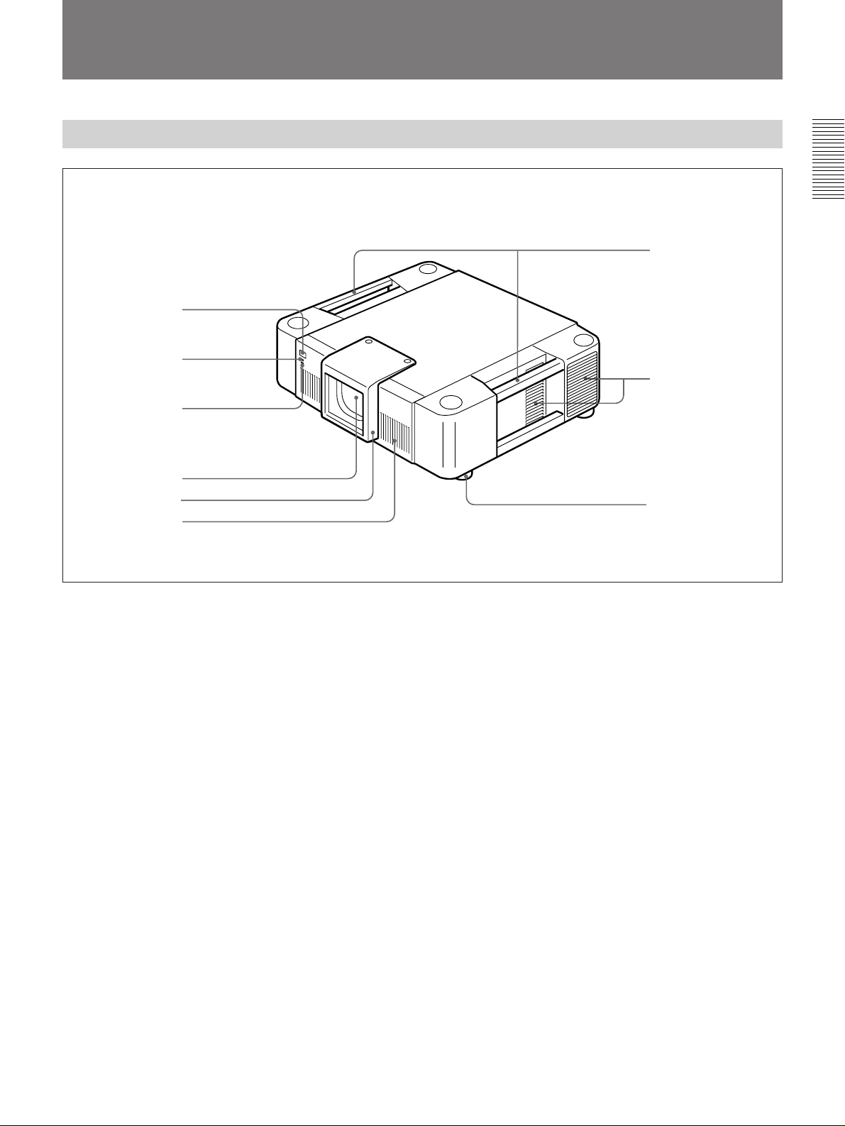
Location and Function of Controls
Front
1
2
3
Overview
7
8
4
5
6
1 Front remote control detector
2 POWER ON lamp
3 STANDBY lamp
4 Lens mount
Attach the projection lens.
5 Lens cover
6 Ventilation holes (intake)
7 Side handles
Used to carry the projector.
9
8 Ventilation holes (intake)
There are also ventilation holes on the opposite side.
9 Adjusters
Used to keep the projector level if it is installed on an
uneven surface.
7 (EN)
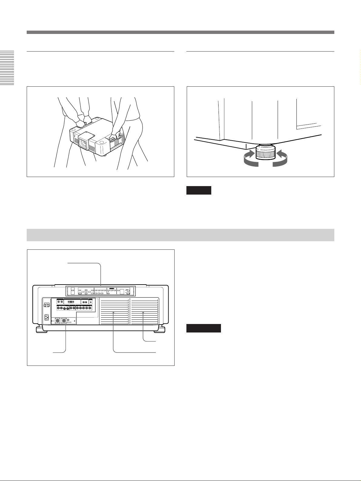
Location and Function of Controls
To carry the projector
Use the side handles as illustrated below.
Overview
To use the adjusters
Turn the screw to adjust the height so that the projector
becomes level.
To raise
the projector
Note
Be careful not to let the projector down on your
fingers.
To lower
the projector
Rear
BREAKER ON/OFF
ON ON
AC IN
4
1
CONTROL S
IN
OUT
PLUG IN
POWER
S VIDEO VIDEO INPUT A
Y IN C IN IN OUT IN OUT
REMOTE 1
IN
MODE
OUT
MUTING
PICTURE
REMOTE
RS-422A
MEMORY
RESET
INDEX
0 0
R/R-Y G/Y B/B-Y SYNC/HD VD
MENU SHIFT PATTERNZOOM FOCUS
ENTER
TRIG
1 Control panel
For details, see page 9.
2 Lamp cover
LENS CONTROL
INPUT SELECT
POWER
BAVIDEO
LIGHT
+–+–+
–
SELECT
VIDEO/S VIDEO
ON
STANDBY u
OFF
g
3 Ventilation holes (exhaust)
4 Input/output connectors
For details, see page 11.
Caution
2
3
Do not block the ventilation holes (both intake and
exhaust). Otherwise, internal heat may build up,
causing fire or damage to the projector.
8 (EN)
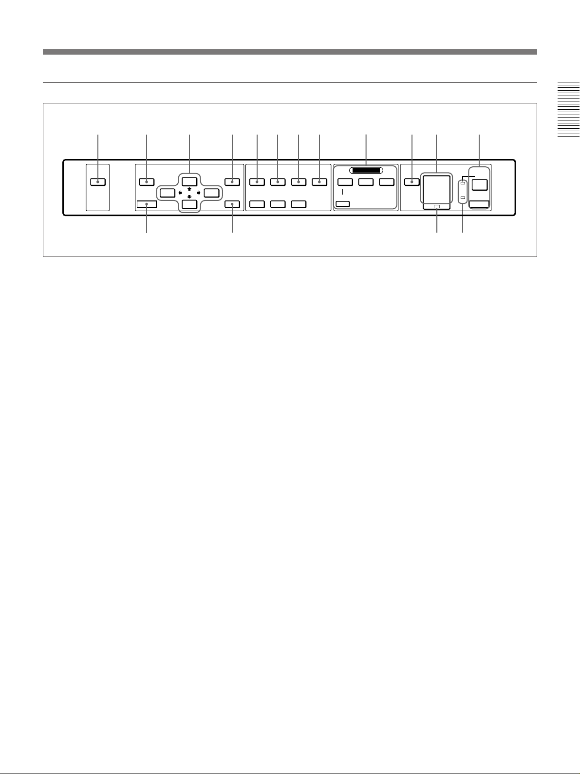
Control panel
31 2 4 5678 0
MUTING
PICTURE
MEMORY
RESET
!⁄
MENU SHIFT PATTERNZOOM FOCUS
+
–
ENTER
!
1 MUTING PICTURE key
Cuts off the picture. The screen turns in black. Press
again to restore the picture.
2 MEMORY key
Stores various adjustment data in the INPUT
SETTING menu into memory.
3 Arrow keys (V/v/B /b)
Used to select the menu or to make various
adjustments.
9
LENS CONTROL
+
+
–
–
SELECT
INPUT SELECT
VIDEO/S VIDEO
9 INPUT SELECT keys
Select the input video signal.
VIDEO: Selects the signal input from the VIDEO or
S VIDEO connectors. To switch the signal, use
the SELECT key.
SELECT: Switches the signal input from the VIDEO
or S VIDEO connectors.
INPUT A: Selects the signal input from the INPUT
A connectors.
INPUT B: Selects the signal input from the INPUT B
section when the optional interface board other
than the IFB-40 is installed.
!` !“
Overview
STANDBY u
!£
POWER
ON
OFF
BAVIDEO
LIGHT
g
!¢
4 MENU key
Displays the on-screen menu. Press again to clear the
menu.
5 SHIFT +/– keys
Adjust the vertical position of the picture.
+ : Picture moves upward.
– : Picture moves downward.
6 ZOOM +/– keys
Adjust the picture size.
+ : Picture size is enlarged.
– : Picture size is reduced.
7 FOCUS +/– keys
Adjust the focus.
+ : Picture focuses forward.
– : Picture focuses farther back.
8 PATTERN key
Displays the test pattern on the screen for focus, zoom
and shift adjustments. Press again to clear the test
pattern.
!… LIGHT key
Turns on the back lighting for the keys on the control
panel when the power is turned on. Press again to turn
off the back lighting. If you do not press any key for
30 seconds, the back lighting turns off automatically.
!` Error code display window
Displays the error codes.
For details on the error codes, see “Error codes” on page
50.
!“ POWER ON/OFF keys
ON : Turns on the projector when the projector is in
standby mode. The POWER indicator lights in
green when the power is turned on.
OFF : Sets the projector to standby mode.
(Continued)
9 (EN)

Location and Function of Controls
!£ Indicators
POWER: Lights in green when the power is turned
on.
Flashes in green while the cooling fan runs after
Overview
turning off the power with the POWER OFF key.
The fan runs for about 15 minutes after turning off
the power.
STANDBY: Lights in red when the BREAKER ON/
OFF switch on the rear panel is turned on.
Once in standby mode, you can turn the projector
on and off with the POWER ON/OFF keys on the
control panel or the Remote Commander.
!¢ Rear remote control detector
! ENTER key
Enters the settings of items in the menu.
!⁄ RESET key
Resets the value of an item to its factory preset value.
This key functions when the menu or a setting item is
displayed on the screen.
10 (EN)
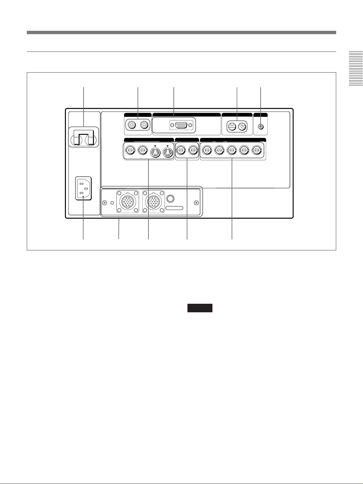
Input/output connectors
123 45
CONTROL S
IN
BREAKER ON/OFF
ON ON
AC IN
REMOTE 1
IN
06
98 7
OUT
PLUG IN
POWER
S VIDEO VIDEO INPUT A
Y IN C IN IN OUT IN OUT
MODE
OUT
1 BREAKER ON/OFF switch
Turns the main power on and off.
2 CONTROL S IN/OUT (control S signal input/
output) jacks (stereo minijack)
Connect to the CONTROL S connectors of other Sony
equipment.
CONTROL S IN/PLUG IN POWER (5 V output)
jack: Connects to the CONTROL S OUT jack on
the supplied Remote Commander with the
supplied Remote Commander cable when using it
as a wired Remote Commander. The power for the
Remote Commander is supplied via this jack.
CONTROL S OUT jack: Outputs the control S
signal.
3 REMOTE RS-422A connector (D-sub 9-pin,
female)
Connects to a computer to control the projector.
REMOTE
RS-422A
INDEX
0
R/R-Y G/Y B/B-Y SYNC/HD VD
TRIG
1
4 INDEX (index number) switches
Set the index number for each projector when using
multiple projectors. You can set the numbers between
01 to 99.
You can check the index number using the menu.
Note
Do not use the index number “9” when using the
supplied Remote Commander.
5 TRIG (trigger output) jack (minijack)
Transmits approximately 5 V trigger signal to external
equipment when the power is on. This is not a power
source.
6 INPUT A connectors
Input the video signals of a component VCR or a
computer.
RGB input connectors (R-R/Y, G/Y, B/B-Y,
SYNC/HD, VD) (BNC-type): Connect to the
monitor output connectors on a component VCR
or a computer.
Overview
(Continued)
11 (EN)
Location and Function of Controls
7 VIDEO connectors (BNC-type)
Connect to external video equipment such as a VCR.
You can use the VIDEO IN connector for bridge
connection.
Overview
IN: Connects to the video output connector of
external video equipment.
OUT: Connects to the video input connector of
external video equipment.
8 S VIDEO connectors
Connect to external video equipment such as a VCR.
You can use the Y IN/C IN connectors or IN connector
for bridge connection.
Y IN/C IN (BNC-type): Connect to the video output
connector of external video equipment.
IN (mini DIN 4-pin): Connects to the Y/C video
output connector of external video equipment.
OUT (mini DIN 4-pin): Outputs the video signal
input through the Y IN/C IN connectors or IN
connector.
Note
If you connect external video equipment to both the Y
IN/C IN connectors and IN connector, the signal from
the Y IN/C IN connectors is selected. In this case,
75-ohm termination is impossible. When projecting the
video signal from the IN connector, do not connect a
signal to the Y IN/C IN connectors.
9 Signal interface board attachment part (INPUT
B)
The IFB-40 Signal Interface Board is installed at the
factory. Other optional signal interface boards can be
inserted to this section instead of the IFB-40.
Indicator (red): Lights up when the input of the
IFB-40 is selected.
REMOTE 1 IN connector (14-pin multi):
Connect to the PC-1271/1271M Signal Interface
Switcher. When connecting two projectors,
connect to the REMOTE 1 OUT connector on the
IFB-40 installed in another projector.
REMOTE 1 OUT connector (14-pin multi):
Connect to the REMOTE 1 IN connector on the
IFB-40.
MODE selector: Turn the control switch of the
MODE selector to the appropriate position
according to the length of the cable connected to
the REMOTE 1 OUT connector.
Cable length
Cable type
Position
SIC-M-1
CCQ-2BRS
1
up to 10 mup to 2 m
SIC-M-5
CCQ-5BRS
CCQ-10BRS
2
SIC-M-15
CCQ-25BRS
SIC-M-25
up to 50 mup to 25 m
SIC-M-50
CCQ-50BRS
43
!… AC IN socket
Connects the supplied AC power cord.
This socket accepts 120 V AC power (for the VPDS1800Q) or 220 to 240 V AC (for the VPDS1800QM).
12 (EN)
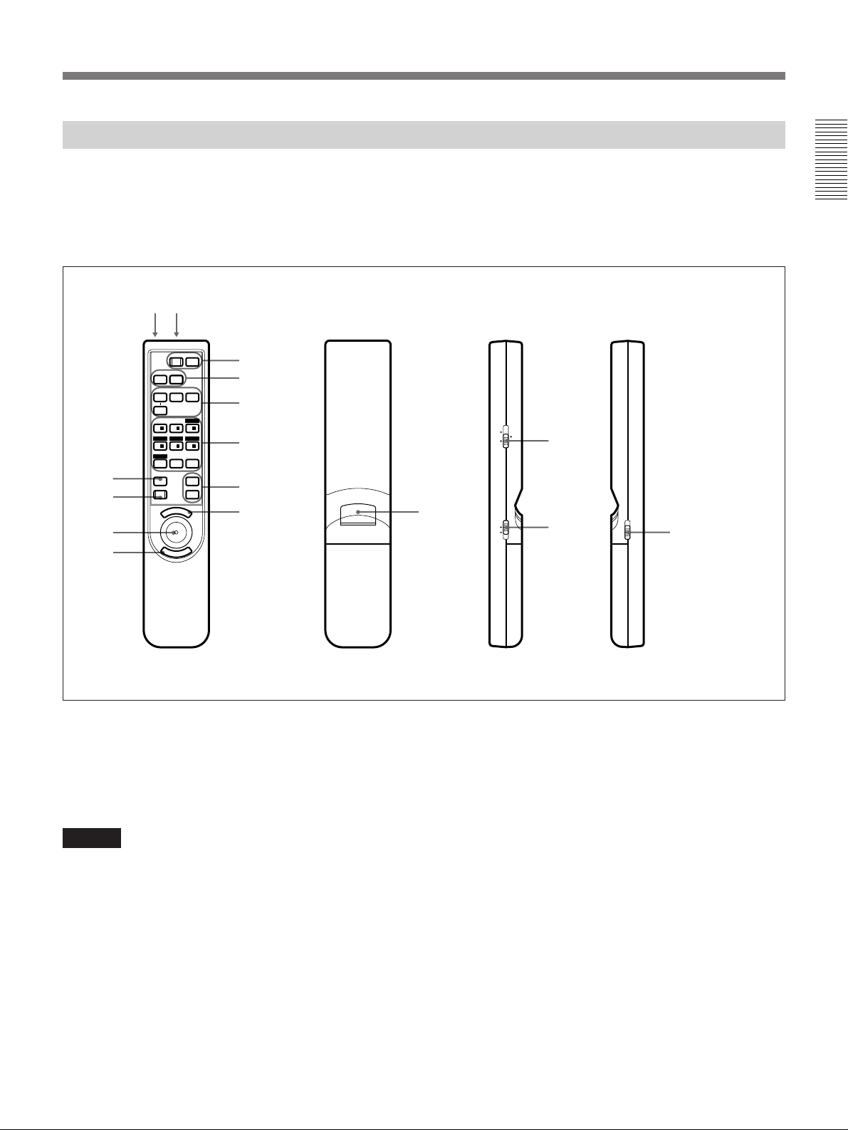
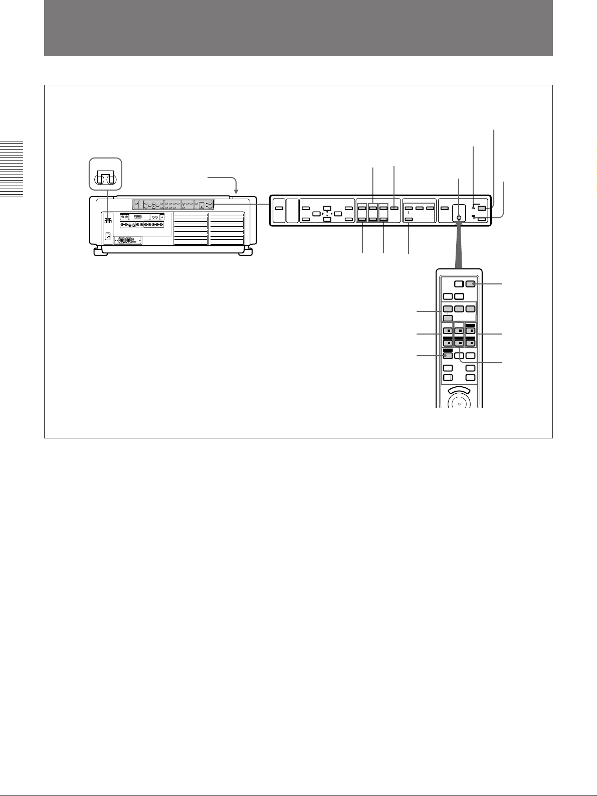
Remote Commander
The Remote Commander can be used as a wireless or
wired Remote Commander.
The keys which have the same names as on the control
panel function identically.
!“ !£
POWER
OFF
!`
!…
MUTING
AUDIO
INPUT SELECT
SELECT
VIDEO/S VIDEO
SWITCHER
+
1/
ZOOMSHIFT
4/ – 5/ – 6/
PATTERN
MEMORY
RESET
M
PIC
AVIDEO
2/ + 3/
87 ALL
N
U
E
/ LENS /INDEX
FOCUS
SECOND
VOLUME
ON
B
+
–
+
–
1
2
3
5
6
7
9
E
R
N
E
8
T
When you use the RM-PJ21 Mouse Receiver (not
supplied), you can control the connected computer
using the Remote Commander.
For details, refer to the instruction manual of the RM-PJ21
Mouse Receiver.
INDEX
LENS SWITCHER
8
MOUSE MENU
4
!¢
LIGHT
!
Overview
Front Rear
1 POWER ON/OFF keys
2 MUTING PIC/AUDIO key
Functions in the same way as the MUTING PICTURE
key on the control panel.
Note
The MUTING AUDIO key does not function with this
unit.
3 INPUT SELECT keys
4 SWITCHER/INDEX/LENS switch
Switches the function of the SWITCHER/INDEX/
LENS keys.
SWITCHER: Designates the input from the signal
interface switcher (not supplied).
INDEX: Selects the index number for each projector
when multiple projectors are connected.
LENS: Adjusts the focus, zoom and shift.
Side (right)
Side (left)
5 SWITCHER/INDEX/LENS keys
Function as described below by switching the position
of the SWITCHER/INDEX/LENS switch.
When the SWITCHER/INDEX/LENS switch is
set to SWITCHER
The SWITCHER/INDEX/LENS keys designate the
input when the signal interface switcher (not supplied)
is connected to the projector.
The SECOND key is used when two switchers are
connected to the projector. To select the input from the
second switcher (when the SINGLE/SECOND/
OTHER switch on the switcher is set to SECOND),
press the SECOND key, and then a number key
between 1 and 8.
(Continued)
13 (EN)
Location and Function of Controls
+
FOCUSZOOMSHIFT
PATTERN
++
–
––
Overview
1
4
Designate the input from the switcher.
23
56
SECOND
87
When the SWITCHER/INDEX/LENS switch is
set to INDEX
The SWITCHER/INDEX/LENS keys are used to
select the index number preset for each projector when
multiple projectors are connected. Press the index
number and ENTER key.
When you select the index number using the Remote
Commander, “INDEX: xx” is displayed on the screen.
(“xx” is the index number of the projector.) On the
screen of the projector that is currently selected, the
index number is displayed in green. The index
numbers for other projectors are displayed in yellow.
This color designation shows you which projector is
currently selected.
Adjusts the shift.
Adjusts the zoom.
Adjusts the focus.
Displays or clears the test pattern.
6 VOLUME +/– keys
These keys do not function with this unit.
7 MENU key
8 ENTER key
9 Joy stick
Used to select the menu or to make various
adjustments.
!… RESET key
1 23
4
Select the index number for each projector.
56
87 ALL
When the SWITCHER/INDEX/LENS switch is
set to LENS
The SWITCHER/INDEX/LENS keys are used for
focus, zoom and shift adjustments and for displaying
or clearing the test pattern on the screen.
!` MEMORY key
!“ CONTROL S OUT (control S signal output)
jack (stereo minijack)
Connects to the CONTROL S IN jack on the projector
when using the Remote Commander as a wired
Remote Commander. In this case, you do not need to
install the batteries in the Remote Commander since
the power is supplied from the CONTROL S IN/PLUG
IN POWER jack on the projector.
!£ Infrared transmitter
!¢ MOUSE/MENU switch
Normally set to MENU.
Set to MOUSE when controlling a computer connected
to the RM-PJ21 Mouse Receiver from the Remote
Commander.
When the MOUSE/MENU switch is set to MOUSE,
the MENU key, ENTER key and joy stick function as
listed on the next page.
14 (EN)
Key Function
IBM1) PC/AT
2)
Macintosh
3)
compatible
MENU Left click ENTER/click
ENTER (front) Right click ENTER/click
ENTER (rear) Right click ENTER/click
Joy stick Corresponds to the movement of the
mouse
! LIGHT switch
Turns on the back lighting for the keys on the Remote
Commander. Press again to turn off the back lighting.
If you do not press any key for 30 seconds, the back
lighting turns off automatically.
Notes on wireless Remote Commander
operation
•Make sure that there is nothing to obstruct the
infrared beam between the Remote Commander and
the remote control detector on the projector.
•The operation range is limited. The shorter the
distance between the Remote Commander and the
projector is, the wider the angle within which the
commander can control the projector.
•The remote control detectors on the projector do not
operate when the Remote Commander is being used
as a wired Remote Commander. When using the
Remote Commander as a wireless Remote
Commander, remove the Remote Commander cable
from both the Remote Commander and the projector.
Overview
Battery installation
1 Push and slide to open the lid.
2 Install the two size AA (R6) batteries (supplied)
with the correct polarity.
Install the battery
from the end.
3 Replace the lid.
Notes on batteries
•Make sure that the battery orientation is correct when
inserting batteries.
•Do not mix an old battery with a new one, or
different types of batteries.
•If you will not use the Remote Commander for a long
time, remove the batteries to avoid damage from
battery leakage. If batteries have leaked, remove
them, wipe the battery compartment dry and replace
the batteries with new ones.
To connect the Remote Commander to the
projector
Rear
CONTROL S
IN
OUT
PLUG IN
POWER
S VIDEO VIDEO INPUT A
Y IN C IN IN OUT IN OUT
REMOTE
RS-422A
R/R-Y G/Y B/B-Y SYNC/HD VD
Remote Commander
cable (supplied)
POWER
OFF
ON
MUTING
PIC
AUDIO
INPUT SELECT
AVIDEO
B
SELECT
VIDEO/S VIDEO
SWITCHER
/ LENS /INDEX
+
+
1/
2/ + 3/
FOCUS
ZOOMSHIFT
–
4/ – 5/ – 6/
PATTERN
SECOND
87 ALL
MEMORY
+
VOLUME
RESET
–
N
E
U
M
E
R
N
E
T
Note on wired Remote Commander operation
You do not need to install the batteries since the power
is supplied from the CONTROL S IN jack on the
projector. Even if batteries are installed in the Remote
Commander, they are not used.
INDEX
0
TRIG
1
..........................................................................................................................................................................................................
1) IBM is a trademark of International Business Machines Corporation, U.S.A.
2) IBM PC/AT is a trademark of International Business Machines Corporation, U.S.A.
3) Macintosh is a trademark of Apple Computer Inc.
15 (EN)
Projecting the Picture on the Screen
2
POWER indicator
Projecting
1
BREAKER ON/OFF
ON ON
BREAKER ON/OFF
ON ON
AC IN
Front remote control
detector
REMOTE
RS-422A
OUT
S VIDEO VIDEO INPUT A
R/R-Y G/Y B/B-YSYNC/HD VD
MODE
OUT
INDEX
TRIG
0 0
CONTROL S
PLUG IN
POWER
Y IN C IN IN OUT IN OUT
REMOTE 1
IN
IN
MUTING
PICTURE MEMORY
RESET
MENU
ENTER
64
LENS CONTROL
ZOOM
SHIFT
+
+
–
–
Rear remote
control detector
INPUT SELECT
PATTERNFOCUS
VIDEO
+
–
SELECT
VIDEO/S VIDEO
LIGHTB
A
STANDBY u
g
POWER
ON
OFF
STANDBY
indicator
357
POWER
OFF
3
7
4
AUDIO
VIDEO
SELECT
SWITCHER
1/
4/
PATTERN
MEMORY
RESET
MUTING
PIC
INPUT SELECT
VIDEO/S VIDEO
+
2/ + 3/
ZOOMSHIFT
–
5/ – 6/
7
E
M
A
/ LENS /INDEX
8 ALL
VOLUME
N
U
FOCUS
SECOND
ON
B
+
–
+
–
2
5
6
1 Set the BREAKER ON/OFF switch on the rear panel to ON.
The STANDBY indicator lights in red and the projector goes into the
standby mode.
2 Press the POWER ON key on the Remote Commander or the control
panel.
The POWER indicator lights in green.
3 Turn on the equipment connected to the projector, and then press the
INPUT SELECT keys on the Remote Commander or the control panel
to select the input source.
VIDEO: Selects the video signal input from the VIDEO or S
VIDEO connectors. To switch the video signal, use the
SELECT key.
SELECT: Switches the video signal input from the VIDEO or S
VIDEO connectors.
INPUT A: Selects the video signal input from the INPUT A
connectors.
INPUT B: Selects the signal input from the INPUT B section when
the optional interface board other than the IFB-40 is
installed.
16 (EN)
4 Press the PATTERN key on the Remote Commander or the control
panel to display the test pattern.
To clear the test pattern, press the PATTERN key again.
5 Press the FOCUS +/– keys on the Remote Commander or the control
panel to adjust the focus.
“FOCUS” appears on the screen during adjustment.
Projecting
Projecting
6 Press the ZOOM +/– keys on the Remote Commander or the control
panel to adjust the zoom.
“ZOOM” appears on the screen during adjustment.
Note
When the VPDL-FP30 fixed short focus lens is attached to the projector,
you cannot use the zoom function.
7 Press the SHIFT +/– keys on the Remote Commander or the control
panel to adjust the vertical position of the picture.
“PICTURE SHIFT” appears on the screen during adjustment.
To cut off the picture
Press the MUTING PICTURE key on the control panel or the MUTING
PIC key on the Remote Commander. To restore the picture, press the
MUTING PICTURE or MUTING PIC key again.
Notes
•The operating temperature guaranteed for the projector is 10°C to 35°C
(50°F to 95°F). When the temperature around the projector is out of the
operating temperature range, no picture may appear on the screen even if
you turn the power on. (75 or 27 lights up in the error code display
window.) In this case, adjust the temperature around the projector.
When the temperature sensor for the lamp power or the lamp housing
functions, the lamp may turn off. (23 or 24 lights up in the error code
display window.)
For details on the error codes, see “Error codes” on page 50.
•Do not look into the lens when the projector lamp is on.
•When you adjust the focus, zoom and shift using the Remote
Commander, set the SWITCHER/INDEX/LENS switch to LENS.
17 (EN)

Projecting the Picture on the Screen
To turn off the power
1 Press the POWER OFF key on the Remote Commander or the control
panel.
The fan continues to run for about 15 minutes to reduce the internal
heat. The POWER indicator flashes in green.
Projecting
2 Make sure that the fan has stopped running and the STANDBY
indicator lights in red, and then set the BREAKER ON/OFF switch to
OFF.
Note
Do not turn off the power with the BREAKER ON/OFF switch while the
fan is still running. Otherwise, internal heat may not be dissipated, causing
damage to the projector.
18 (EN)
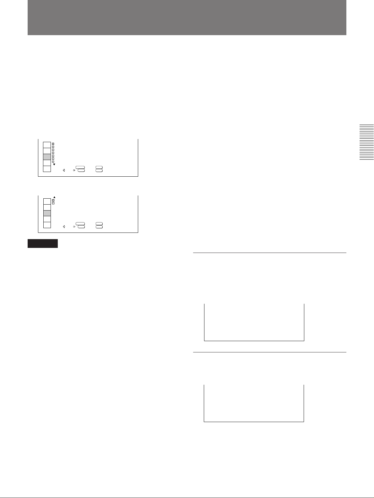
Using the Menu
Adjustments and Settings Using the Menu
The projector is equipped with an on-screen menu for
making various adjustments and settings.
To select the language used in the menu, see page
28.
Basic operation
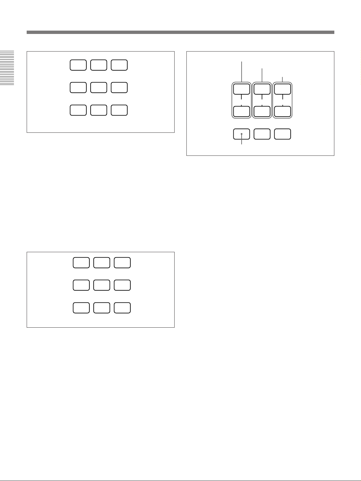
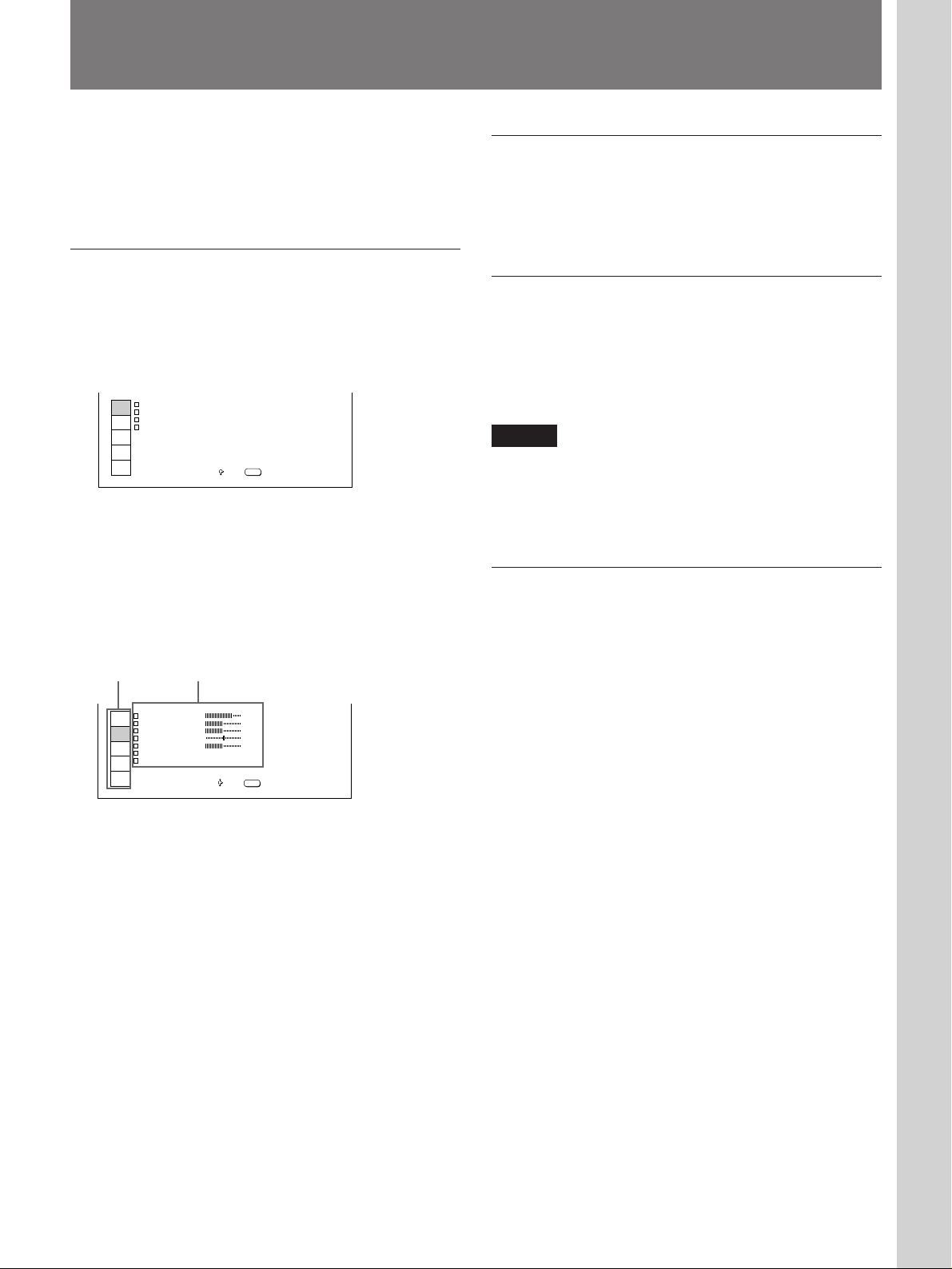
1 Press the MENU key.
The menu display appears.
The menu presently selected is highlighted in blue.
INPUT
SELECT
PICTURE
CTRL
INPUT
SETTING
SET
SETTING
INPUT
INFO
NPUT SELECTI
V DEOI
V DEOI:
I NPUT - A
I NPUT - B
SW TCHER
SW ER - 1
I:
SEL: EXIT:
'1
MENU
2 Select a menu using the V or v key on the control
panel, then press the b or ENTER key.
On the Remote Commander, move the joy stick up
or down to select a menu, then move it to the right
or press the ENTER key.
Now you can select the item in the menu.
Menus Items
P CTURE CTRL I
INPUT
CONTRAST
SELECT
BR GHTI
PICTURE
COLOR
CTRL
HUE
INPUT
SHARP
SETTING
COLOR SYS : AUTO
SET
S GI TYPE : NORMAL
SETTING
INPUT
INFO
SEL: EXIT:
80
50
50
50
50
MENU
To clear the menu display
Press the MENU key.
The menu display disappears automatically if no key is
pressed for approximately one minute.
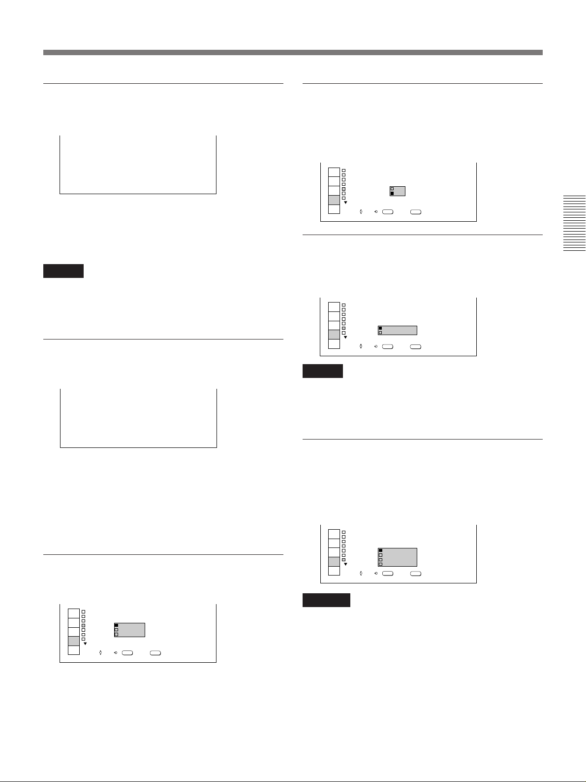
To reset the setting
Press the RESET key.
The message “RESET complete!” appears on the
screen, and the setting displayed on the screen is reset
to its factory preset setting.
Adjustments and Settings Using the Menu
Note
When you press the RESET key for the items that
cannot be reset, the message “Not applicable!” appears
on the screen. The settings are not reset to their factory
preset settings.
Memory of the settings
The settings other than in the INPUT SETTING menu
are automatically stored in memory. For the settings in
the INPUT SETTING menu, press the MEMORY key
on either the control panel or the supplied Remote
Commander.
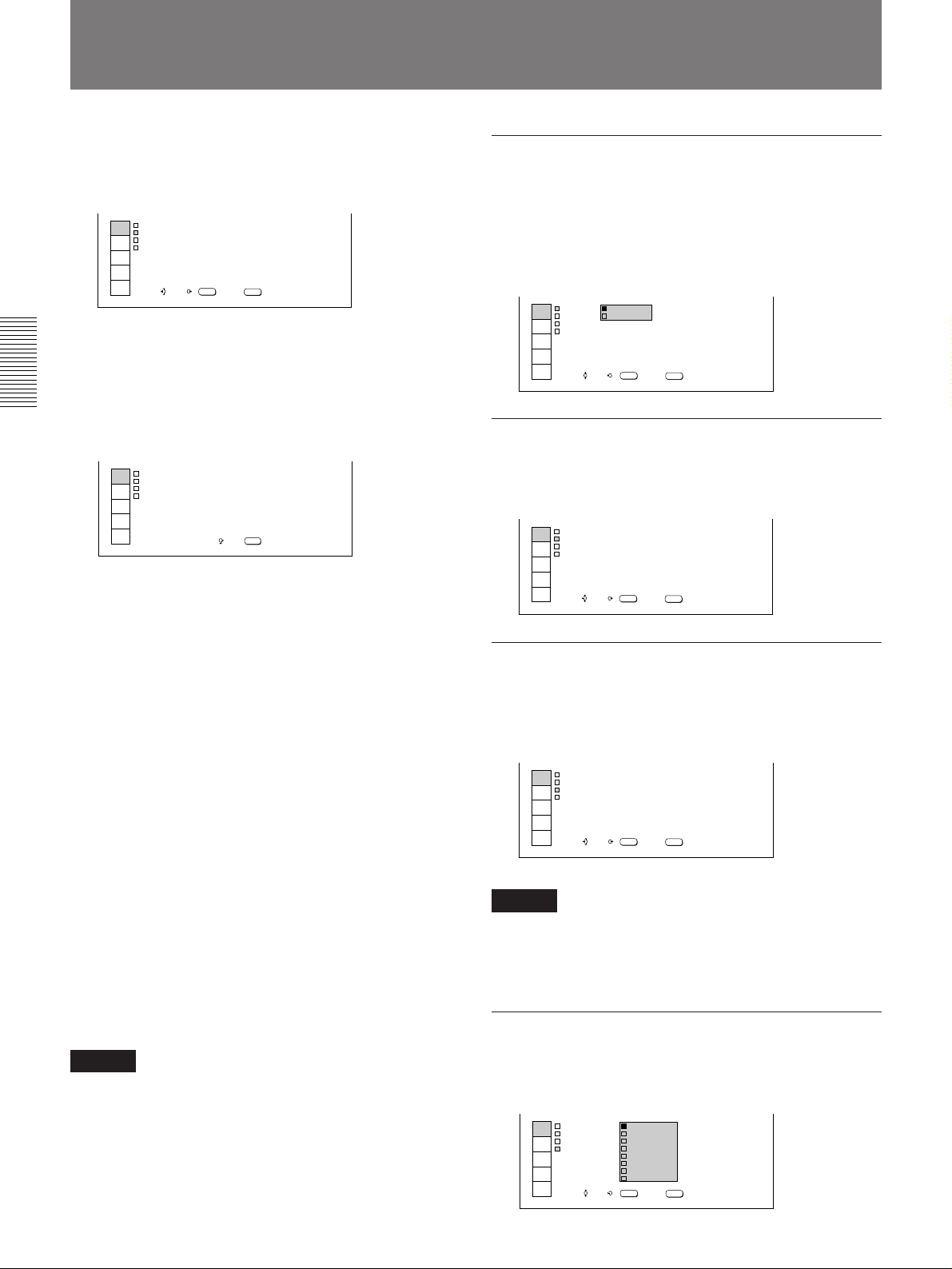
3 Make adjustment or setting on the selected item.
For details, see the relevant menu pages.
19 (EN)
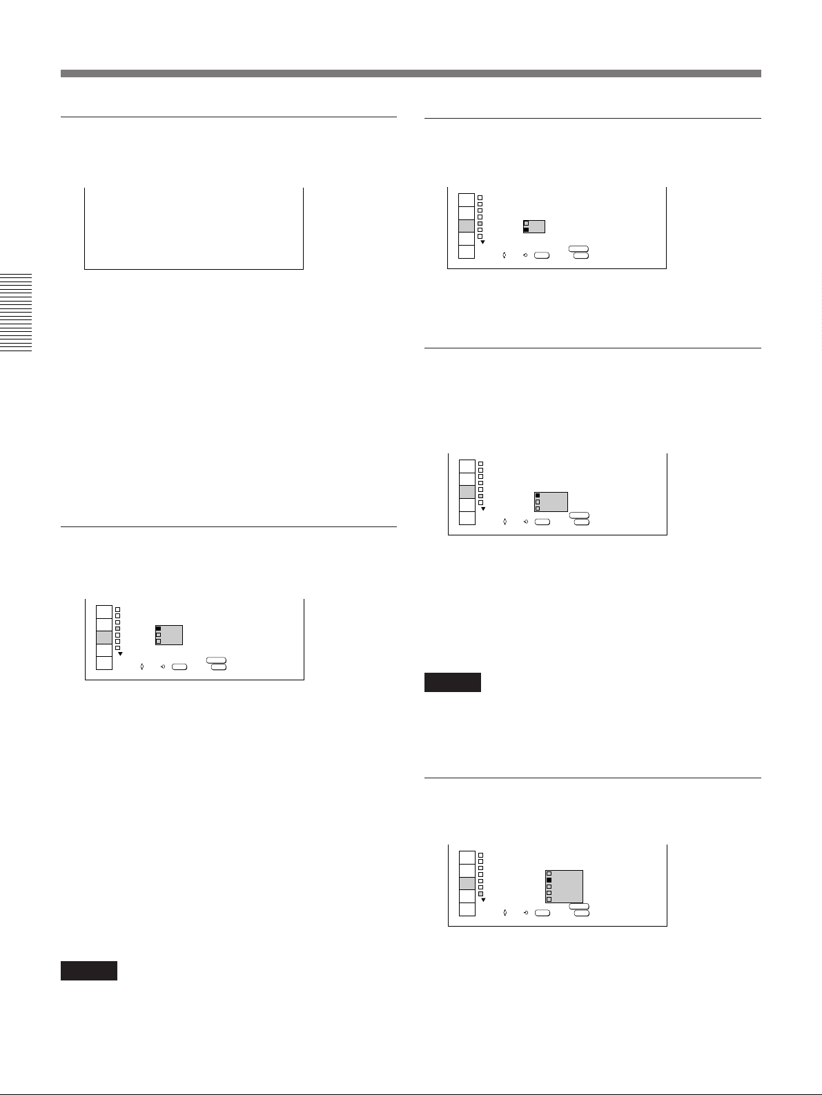
The INPUT SELECT Menu
The INPUT SELECT menu is used for selecting the
input signal.
Adjustable items are displayed in green.
INPUT
SELECT
PICTURE
CTRL
INPUT
SETTING
SET
SETTING
INPUT
INFO
NPUT SELECTI
V DEOI
V DEOI:
I NPUT - A
I NPUT - B
SW TCHER
SEL: EXIT:
SW ER - 1
SET:
/
'1
ENTER
I:
MENU
Operation
1 Press the MENU key.
Adjustments and Settings Using the Menu
The menu display appears.
The menu presently selected is highlighted in blue.
INPUT
SELECT
PICTURE
CTRL
INPUT
SETTING
SET
SETTING
INPUT
INFO
NPUT SELECTI
V DEOI:
V DEOI
I NPUT - A
I NPUT - B
SW TCHER
SW ER - 1
I:
SEL: EXIT:
'1
MENU
2 Select the INPUT SELECT menu using the V or v
key on the control panel, then press the b or
ENTER key.
On the Remote Commander, move the joy stick up
or down to select the INPUT SELECT menu, then
move it to the right or press the ENTER key.
Now you can select the item in the menu.
3 Select the input signal using the V or v key on the
control panel.
On the Remote Commander, move the joy stick up
or down to select the input signal.
When you select “VIDEO” or “SWITCHER,”
settings to be selected are displayed.
Select the input signal following the procedure
below.
Select the input signal using the V or v key on the
control panel, then press the B or ENTER key.
On the Remote Commander, move the joystick up
or down to select the input signal, then move it to
the left or press the ENTER key.
The previous screen is restored.
VIDEO
Selects the video signal input from the VIDEO or S
VIDEO connectors.
If you select S-VIDEO when you have connected video
equipment to both the Y IN/C IN and IN connectors, the
signal from the Y IN/C IN connectors is selected.
INPUT
SELECT
PICTURE
CTRL
INPUT
SETTING
SET
SETTING
INPUT
INFO
NPUT SELECTI
V DEOI
V DEOI:
I NPUT - S
I NPUT - B
SW TCHER
- V DEOI
SW ER - 1
SET:
/
'1
ENTER
I:
SEL: EXIT:
MENU
INPUT-A
Selects the video signal input from the INPUT A
connectors.
INPUT
SELECT
PICTURE
CTRL
INPUT
SETTING
SET
SETTING
INPUT
INFO
NPUT SELECTI
V DEOI
V DEOI:
I NPUT - A
I NPUT - B
SW TCHER
SEL: EXIT:
SW ER - 1
SET:
/
'1
ENTER
I:
MENU
INPUT-B
Selects the signal input from the INPUT B section
when the optional interface board other than the IFB40 is installed.
INPUT
SELECT
PICTURE
CTRL
INPUT
SETTING
SET
SETTING
INPUT
INFO
NPUT SELECTI
V DEOI
V DEOI:
I NPUT - A
I NPUT - B
SW TCHER
SEL: EXIT:
SW ER - 1
SET:
/
'1
ENTER
I:
MENU
Note
When the IN/OUT switch on the IFB-12 Signal
Interface Board (not supplied) installed in the projector
is set to OUT, you cannot select this item.
SWITCHER
Note
When you change the input signal, the picture size may
also change.
20 (EN)
Selects the input signal from the equipment connected
to the signal interface switcher (not supplied).
INPUT
SELECT
PICTURE
CTRL
INPUT
SETTING
SET
SETTING
INPUT
INFO
NPUT SELECTI
V DEOI
I NPUT - A
I NPUT - B
SW TCHER
SW ER - 1'1
V DI
SW ER - 2'1
SW ER - 3'1
SW ER - 4'1
I:
SW ER - 5'1
SW ER - 6'1
SW ER - 7'1
SW ER - 8'1
ENTER
SET:SEL: EXIT:
/
MENU
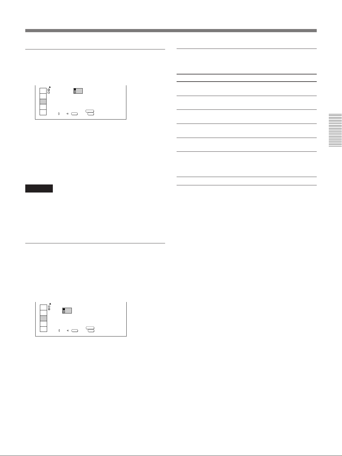
The PICTURE CTRL Menu
The PICTURE CTRL menu is used for adjusting the
picture.
Adjustable items are displayed in green.
P CTURE CTRL I
INPUT
CONTRAST
SELECT
BR GHTI
PICTURE
COLOR
CTRL
HUE
INPUT
SHARP
SETTING
COLOR SYS : AUTO
SET
S GI TYPE : NORMAL
SETTING
INPUT
INFO
SET:SEL: EXIT:
/
ENTER
RESET:
80
50
50
50
50
RESET
MENU
Operation
1 Press the MENU key.
The menu display appears.
The menu presently selected is highlighted in blue.
2 Select the PICTURE CTRL menu using the V or v
key on the control panel, then press the b or
ENTER key.
On the Remote Commander, move the joy stick up
or down to select the PICTURE CTRL menu, then
move it to the right or press the ENTER key.
CONTRAST
Adjusts the picture contrast.
CONTRAST :80
The higher the setting level is, the stronger the
contrast.
The lower the setting level is, the weaker the contrast.
Adjustments and Settings Using the Menu
BRIGHT (brightness)
Adjusts the picture brightness.
BR GHT :50I
Now you can select the item in the menu.
3 Select an item using the V or v key on the control
panel, then press the b or ENTER key.
On the Remote Commander, move the joy stick up
or down to select an item, then move it to the right
or press the ENTER key.
4 Make adjustment or setting on the selected item.
When changing the adjustment level:
To increase the value, press the V or b key.
On the Remote Commander, move the joy stick up
or to the right.
To decrease the value, press the v or B key.
On the Remote Commander, move the joy stick
down or to the left.
To enter the value and return to the previous
screen, press the ENTER key.
When changing the setting:
Use the V or v key on the control panel to change
the setting, then press the B or ENTER key.
On the Remote Commander, move the joy stick up
or down to change the setting, then move it to the
left or press the ENTER key.
The previous screen is restored.
The higher the setting level is, the brighter the picture.
The lower the setting level is, the darker the picture.
COLOR (color intensity)
Adjusts the color intensity.
COLOR:50
The higher the setting level is, the deeper the intensity.
The lower the setting level is, the lighter the intensity.
(Continued)
21 (EN)
The PICTURE CTRL Menu
HUE
Adjusts the skin tone.
HUE :50
As the setting level goes higher, the picture becomes
greenish.
As the setting level goes lower, the picture becomes
purplish.
Adjustments and Settings Using the Menu
SHARP (sharpness)
Adjusts the picture sharpness.
SHARP :50
SIG TYPE (signal type)
Selects the normal, letter box, or squeeze signal.
P CTURE CTRL I
INPUT
CONTRAST
SELECT
BR GHTI
PICTURE
COLOR
CTRL
HUE
INPUT
SHARP
SETTING
COLOR SY
SET
S GI TYPE
SETTING
INPUT
INFO
SET:SEL: EXIT:
/
NORMAL: Normally set to this position.
P CTURE CTRL I
INPUT
CONTRAST
SELECT
BR GHTI
PICTURE
COLOR
CTRL
HUE
INPUT
SHARP
SETTING
COLOR SY
SET
S GI TYPE
SETTING
INPUT
INFO
SET:SEL: EXIT:
LETTER BOX: Set to this position when black
zones appear at the top and bottom of the screen.
P CTURE CTRL I
INPUT
CONTRAST
SELECT
BR GHTI
PICTURE
COLOR
CTRL
HUE
INPUT
SHARP
SETTING
COLOR SY
SET
S GI TYPE
SETTING
INPUT
INFO
SET:SEL: EXIT:
/
NORMAL
LETTER BOX
SQUEEZE
ENTER
NORMAL
LETTER BOX
SQUEEZE
ENTER
/
NORMAL
LETTER BOX
SQUEEZE
ENTER
80
50
50
50
50
80
50
50
50
50
80
50
50
50
50
MENU
MENU
MENU
The higher the setting level is, the sharper the picture.
The lower the setting level is, the softer the picture.
COLOR SYS (color system)
Selects the color system of the input signal.
P CTURE CTRL I
INPUT
CONTRAST
SELECT
BR GHTI
PICTURE
COLOR
CTRL
HUE
INPUT
SHARP
SETTING
COLOR SYS
SET
S GI TYPE :
SETTING
INPUT
INFO
SET:SEL: EXIT:
/
Normally set to AUTO.
If the picture is distorted or colorless, select the color
system corresponding to the input signal.
:
N
ENTER
AUTO
NTSC
PAL
SECAM
NTSC
PAL M-
80
50
3. 58
4. 43
MENU
SQUEEZE: Set to this position when a wide-screen
picture appears on the screen.
P CTURE CTRL I
INPUT
CONTRAST
SELECT
BR GHTI
PICTURE
COLOR
CTRL
HUE
INPUT
SHARP
SETTING
COLOR SY
SET
S GI TYPE
SETTING
INPUT
INFO
SET:SEL: EXIT:
NORMAL
LETTER BOX
SQUEEZE
ENTER
/
80
50
50
50
50
MENU
The items that cannot be adjusted
depending on the type of input signal
Item Cannot be adjusted with
COLOR HDTV signal, RGB (other than 15 kHz)
HUE Input signal other than on NTSC 3.58/4.43
SHARP RGB (other than 15 kHz) signal
COLOR SYS Signals other than video signal
SIG TYPE Input signal on PAL or SECAM, HDTV
signal or black-and-white signal
signal, RGB (other than 15 kHz/60 Hz)
signal or component signal
1)
..........................................................................................................................................................................................................
1) NTSC4.43 is the color system for playing back a video tape recorded on NTSC using an NTSC4.43 system VCR.
22 (EN)
The INPUT SETTING Menu
The INPUT SETTING menu is used for adjusting the
input signal.
Adjustable items are displayed in green.
The INPUT SETTING menu consists of two pages.
To change the page, press the V or v key until the page
changes when selecting an item.
On the Remote Commander, move the joy stick up or
down until the page changes when selecting an item.
<Page 1>
INPUT
SELECT
PICTURE
CTRL
INPUT
SETTING
SET
SETTING
INPUT
INFO
NPUT SETT NGI
DOT PHASE
DOT
CLOCK
SH FTI::H
CLAMP
F LTER
I
SYNC SEL
COLOR
MEMORY:
I
:
4
123
123 :V 123
:
AUTO
OFF
:
: AUTO
TEMP
: 6500
MEMORY
RESET:
ENTER
SET:SEL: EXIT:
/
RESET
MENU
<Page 2>
INPUT
SELECT
PICTURE
CTRL
INPUT
SETTING
SET
SETTING
INPUT
INFO
NPUT SETT NGI
SCAN CONV::
BLKG
MEMORY:
I
ON
ON
MEMORY
RESET:
ENTER
SET:SEL: EXIT:
/
RESET
MENU
Note
Depending on the input signal, page 2 may not be
displayed.
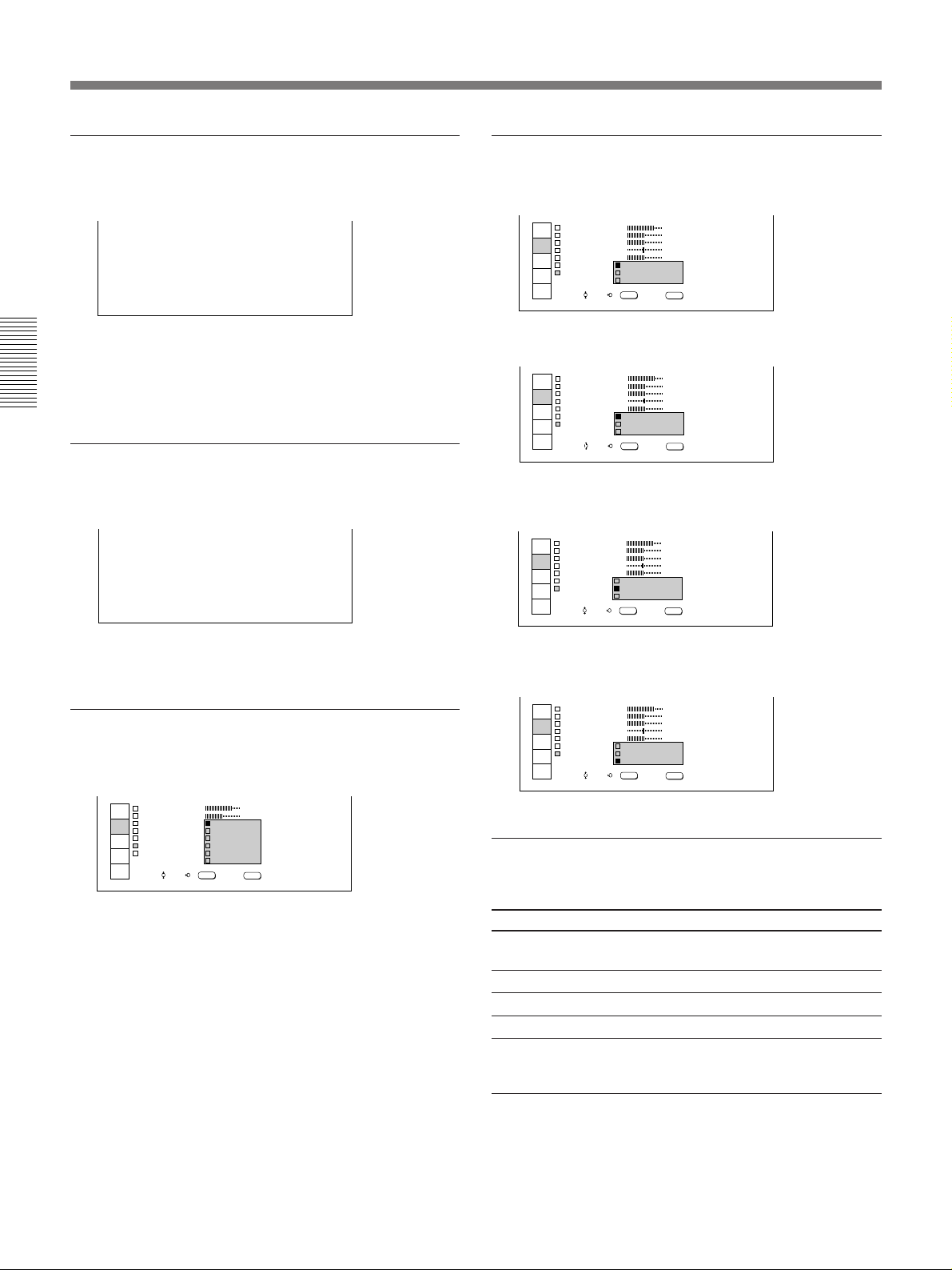
4 Make adjustment or setting on the selected item.
When changing the adjustment level:
To increase the value, press the V or b key.
On the Remote Commander, move the joy stick up
or to the right.
To decrease the value, press the v or B key.
On the Remote Commander, move the joy stick
down or to the left.
To enter the value and return to the previous
screen, press the ENTER key.
When changing the setting:
Use the V or v key on the control panel to change
the setting, then press the B or ENTER key.
On the Remote Commander, move the joy stick up
or down to change the setting, then move it to the
left or press the ENTER key.
The previous screen is restored.
5 Press the MEMORY key on either the control
panel or the supplied Remote Commander after
adjustment or setting.
DOT PHASE
Adjustments and Settings Using the Menu
Operation
1 Press the MENU key.
The menu display appears.
The menu presently selected is highlighted in blue.
2 Select the INPUT SETTING menu using the V or
v key on the control panel, then press the b or
ENTER key.
On the Remote Commander, move the joy stick up
or down to select the INPUT SETTING menu,
then move it to the right or press the ENTER key.
Now you can select the item in the menu.
3 Select an item using the V or v key on the control
panel, then press the b or ENTER key.
On the Remote Commander, move the joy stick up
or down to select an item, then move it to the right
or press the ENTER key.
Adjusts the dot phase to fit picture pixel of the input
signal to that of DMD
TM 1)
.
Adjust the setting level to obtain the sharpest picture.
DOT PHASE :4
DOT CLOCK
Adjusts the horizontal length of the picture.
DOT
CLOCK : 1 2 3
(Continued)
..........................................................................................................................................................................................................
1) DMDTM is a trademark of Texas Instruments Incorporated, U.S.A.
23 (EN)
The INPUT SETTING Menu
SHIFT
Adjusts the position of the picture.
SH FTI:H 123 :V 123
H (horizontal): Adjusts the horizontal position of
the picture. As the value increases, the picture
moves to the right. As the value decreases, the
picture moves to the left.
Adjustments and Settings Using the Menu
V (vertical): Adjusts the vertical position of the
picture. As the value increases, the picture moves
up. As the value decreases, the picture moves
down.
Use the B or the b key to adjust the horizontal
position, and the V or v key to adjust the vertical
position.
CLAMP
Corrects the luminance of the picture.
INPUT
SELECT
PICTURE
CTRL
INPUT
SETTING
SET
SETTING
INPUT
INFO
NPUT SETT NGI
DOT PHASE
DOT
CLOCK
SH FTI::H
CLAMP
F LTER
I
SYNC S TO
COLOR
CLAMP is used as a standard for correctly setting the
black level of a picture. The standard position of the
clamp depends on the kind of sync signal being used.
Normally, the projector CPU judges the signal and sets
the position automatically. However, the CPU can
misjudge the signal because of noise. If the luminance
of the picture seems to be incorrect, change the clamp
position.
AUTO: Automatic setting mode. Normally set to this
position.
SonG (sync on green): Set to this position if the
black seems too light or greenish.
H/C (horizontal/composite): Set to this position if
the picture is too dark or luminance is unstable.
I
:
4
123
123 :V 123
:
AUTO
SonG
H/C
TEMP
: 6500
MEMORY:
ENTER
SET:SEL: EXIT:
/
MEMORY
MENU
FILTER
Reduces the line patterns that appear on the picture.
INPUT
DOT PHASE
SELECT
DOT
PICTURE
SH FTI::H
CTRL
CLAMP
INPUT
F LTER
SETTING
SYNC SE TO
SET
COLOR
SETTING
INPUT
INFO
NPUT SETT NGI
CLOCK
I
I
:
4
123
123 :V 123
:
AUTO
ON
:
OFF
TEMP
: 6500
MEMORY:
ENTER
SET:SEL: EXIT:
/
MEMORY
MENU
The picture will lose some clarity, but the line patterns
will be reduced.
SYNC SEL (sync signal selection)
Selects the sync signal when both the S on G signal
and separate sync signal/composite sync signal are
input as RGB signals.
INPUT
DOT PHASE
SELECT
DOT
PICTURE
SH FTI::H
CTRL
CLAMP
INPUT
F LTER
I
SETTING
SYNC SEL :
SET
COLOR
SETTING
INPUT
INFO
NPUT SETT NGI
CLOCK
I
:
4
123
123 :V 123
:
AUTO
: OFF
AUTO
S
oGn
TEM
H
C,V/
MEMORY:
ENTER
SET:SEL: EXIT:
/
MEMORY
MENU
AUTO: Selects the sync signal automatically.
Normally set to this position.
SonG (sync on green): Selects the S on G signal.
H/C, V (horizontal/composite, vertical): Selects
the separate (horizontal/vertical) sync signal or
composite sync signal.
Note
If the luminance is still incorrect after changing the
clamp setting, check the input signal and the
connections.
COLOR TEMP (color temperature)
Selects the color temperature.
INPUT
SELECT
PICTURE
CTRL
INPUT
SETTING
SET
SETTING
INPUT
INFO
NPUT SETT NGI
DOT PHASE
DOT
CLOCK
SH FTI::H
CLAMP
I
F LTER
SYNC SEL : AU
COLOR
I
:
4
123
123
9300
:
AUTO
6500
: OFF
5400
3200
TEMP
:
PRESET
MEMORY:
ENTER
SET:SEL: EXIT:
/
MEMORY
MENU
Note
If the luminance is still incorrect after changing the
clamp setting, check the input signal and the
connections.
24 (EN)
SCAN CONV (scan convertor)
Change the setting when the input signal is other than
800 × 600 pixels.
INPUT
SELECT
PICTURE
CTRL
INPUT
SETTING
SET
SETTING
INPUT
INFO
NPUT SETT NGI
SCAN CONV::
BLKG
ON: Displays the picture according to the screen size.
The picture will lose some clarity.
OFF: Displays the picture while matching one pixel
of input picture elements to that of the DMD. The
picture will be clear. When the input signal is
more than 800 × 600 pixels, a part of the screen
may be cut off.
Notes
•When you switch the input signal, the size of the
picture may be changed.
•You may not be able to select OFF when the vertical
frequency of the input signal is 62 Hz or less and the
horizontal frequency is 60 kHz or more.
I
ON
OFF
ON
MEMORY:
ENTER
SET:SEL: EXIT:
/
MEMORY
MENU
The items that cannot be adjusted
depending on the type of input signal
Item Cannot be adjusted with
DOT PHASE Signals other than RGB signal (except 15
kHz)
DOT CLOCK Signals other than RGB signal (except 15
kHz)
SHIFT Signals other than RGB signal (except 15
kHz)
CLAMP Signals other than RGB signal (except 15
kHz)
FILTER Signals other than RGB signal (except 15
kHz)
SCAN CONV Composite video, Y/C video input signal,
HDTV signal or some input signals at
horizontal frequency of 62 Hz or less or at
vertical frequency of 60 kHz or more
BLKG RGB signal (except 15 kHz)
Adjustments and Settings Using the Menu
BLKG (blanking)
Set to ON to mask the upper, lower, left and right parts
of the screen. A noise on these parts will be reduced
(“ON” is the factory setting.)
Set to OFF if necessary as the picture to be displayed
is small.
INPUT
SELECT
PICTURE
CTRL
INPUT
SETTING
SET
SETTING
INPUT
INFO
NPUT SETT NGII
SCAN CONV::
BLKG
ON
ON
OFF
MEMORY:
ENTER
SET:SEL: EXIT:
/
MEMORY
MENU
25 (EN)
The SET SETTING Menu
The SET SETTING menu is used for changing the
default settings.
Adjustable items are displayed in green.
The SET SETTING menu consists of three pages.
To change the page, press the V or v key until the page
changes when selecting an item.
On the Remote Commander, move the joy stick up or
down until the page changes when selecting an item.
<Page 1>
INPUT
SELECT
PICTURE
CTRL
INPUT
SETTING
Adjustments and Settings Using the Menu
SET
SETTING
INPUT
INFO
SET SETT NG
FOCUS
ZOOM
P CTUREI
STATUS
P C
I
I NPUT - A
I NPUT - B : RGB
I
SH FTI
:
O
N
: OFF
MUT NGI
:RGB
ENTER
SET:SEL: EXIT:
/
MENU
<Page 2>
INPUT
SELECT
PICTURE
CTRL
INPUT
SETTING
SET
SETTING
INPUT
INFO
SET SETT NG
LANGUAGE
H
POLAR TY
V POLAR TY
POWER
L GHT
I
IS RCS
I
: ENGL SHI
NORMAL
I
:
:
NORMAL
I
SAV NG
I : OFF
:O
N
BOOST
I
RECE VER
FRONT&REAR
ENTER
SET:SEL: EXIT:
/
MENU
<Page 3>
INPUT
SELECT
PICTURE
CTRL
INPUT
SETTING
SET
SETTING
INPUT
INFO
SET SETT NGI
1
:S
SCREEN
CONPONENT
SMPTE
NDEX
I:0
1
SET:SEL: EXIT:
/
FORMAT
/ EBU N 1 0
ENTER
:
-
MENU
Operation
3 Select an item using the V or v key on the control
panel, then press the b or ENTER key.
On the Remote Commander, move the joy stick up
or down to select an item, then move it to the right
or press the ENTER key.
4 Make adjustment or setting on the selected item.
When changing the adjustment level:
To increase the value, press the V or b key.
On the Remote Commander, move the joy stick up
or to the right.
To decrease the value, press the v or B key.
On the Remote Commander, move the joy stick
down or to the left.
To enter the value and return to the previous
screen, press the ENTER key.
When changing the setting:
Use the V or v key on the control panel to change
the setting, then press the B or ENTER key.
On the Remote Commander, move the joy stick up
or down to change the setting, then move it to the
left or press the ENTER key.
The previous screen is restored.
FOCUS
Adjusts the focus.
1 Press the MENU key.
The menu display appears.
The menu presently selected is highlighted in blue.
2 Select the SET SETTING menu using the V or v
key on the control panel, then press the b or
ENTER key.
On the Remote Commander, move the joy stick up
or down to select the SET SETTING menu, then
move it to the right or press the ENTER key.
Now you can select the item in the menu.
26 (EN)
+
FOCUS
To adjust the focus, press the V/b key or v/B key. On
the Remote Commander, move the joy stick up/right or
down/left.
ZOOM
PIC MUTING (picture muting)
Adjusts the zoom.
+
ZOOM
To zoom in, press the V or b key. On the Remote
Commander, move the joy stick up or to the right.
To zoom out, press the v or B key. On the Remote
Commander, move the joy stick down or to the left.
Note
When the VPDL-FP30 fixed short focus lens is
attached to the projector, you cannot use the zoom
function.
PICTURE SHIFT
Adjusts the vertical position of the picture.
Set to ON to cut off the picture.
When set to ON, “PIC MUTING” appears on the
screen.
INPUT
SELECT
PICTURE
CTRL
INPUT
SETTING
SET
SETTING
INPUT
INFO
SET SETT NG
FOCUS
ZOOM
P CTUREI
STATUS
I
P C
I NPUT - A
I NPUT - B
I
SH FTI
ON
:
ON
:
MUT NGI
RGB
:
OFF
RGB
:
ENTER
SET:SEL: EXIT:
/
MENU
INPUT-A
Selects the RGB or component signal input from the
INPUT A connectors.
INPUT
SELECT
PICTURE
CTRL
INPUT
SETTING
SET
SETTING
INPUT
INFO
SET SETT NG
FOCUS
ZOOM
P CTUREI
STATUS
P C
I
I NPUT - A
I NPUT - B
Note
Unless the signal type is correctly selected, the picture
noise may appear. For example, color balance may be
incorrect.
I
SH FTI
ON
:
: OFF
MUT NGI
RGB
:
COMPOMENT
:
ENTER
SET:SEL: EXIT:
/
MENU
Adjustments and Settings Using the Menu
PICTURE SHIFT
+
To move the picture up, press the V or b key. On the
Remote Commander, move the joy stick up or to the
right.
To move the picture down, press the v or B key. On
the Remote Commander, move the joy stick down or
to the left.
STATUS (on-screen display)
Sets up the on-screen display.
INPUT
SELECT
PICTURE
CTRL
INPUT
SETTING
SET
SETTING
INPUT
INFO
SET SETT NG
FOCUS
ZOOM
P CTUREI
STATUS
P C
I
I NPUT - A
I NPUT - B : RGB
ON: Displays all the on-screen displays.
OFF: Turns off the on-screen displays except “NO
INPUT,” “PIC MUTING,” and warning messages.
ALL OFF: Turns off all the on-screen displays
except warning messages.
I
SH FTI
ON
:
OFF
MUT
A OFFLL
ENTER
SET:SEL: EXIT:
/
MENU
INPUT-B
Selects the RGB, component, composite video or Svideo signal input from the connectors on the IFB-12
Signal Interface Board (not supplied) installed in the
INPUT B slot of the projector.
INPUT
SELECT
PICTURE
CTRL
INPUT
SETTING
SET
SETTING
INPUT
INFO
SET SETT NG
FOCUS
ZOOM
P CTUREI
STATUS
P C
I
I NPUT - A
I NPUT - B
Notes
•You cannot select this item when you have not
installed the IFB-12 Signal Interface Board (not
supplied) in the projector.
•Unless the signal type is correctly selected, the
picture noise may appear. For example, color balance
may be incorrect.
I
SH FTI
ON
:
RGB
MUT I
COMPONENT
:
V DEO
I
:
V DEO
S
I
-
ENTER
SET:SEL: EXIT:
/
MENU
(Continued)
27 (EN)
The SET SETTING Menu
LANGUAGE
Selects the language used for the menu and on screen
displays.
INPUT
SELECT
PICTURE
CTRL
INPUT
SETTING
SET
SETTING
INPUT
INFO
SET SETT NG
LANGUAGE
H
POLAR T
V POLAR T
POWER
L GHT
I
IS RCS
I
ENGL SH
:
I
I
FRANCA S
DEUTSCH
I
SAV
TAL ANO
I
I
ESPANOL
BOO
I
RECE VER
FRONT&REAR
ENTER
SET:SEL: EXIT:
/
I
MENU
Available languages are English, French, German,
Italian, and Spanish.
Adjustments and Settings Using the Menu
H POLARITY (horizontal polarity)
Set to REVERSE to reverse the horizontal orientation
of the picture.
INPUT
SELECT
PICTURE
CTRL
INPUT
SETTING
SET
SETTING
INPUT
INFO
SET SETT NG
LANGUAGE
H
POLAR TY
V POLAR TY
POWER
L GHT
I
IS RCS
I
: ENGL SHI
NORMAL
I
:
:
REVERSE
I
SAV NG
I : OFF
:O
N
BOOST
I
RECE VER
FRONT&REAR
ENTER
SET:SEL: EXIT:
/
MENU
LIGHT BOOST
When you set this item to ON, the lamp power is
boosted and the display gets brighter. You can select
ON when you use the projector at 200 to 240 V.
If you use the projector at 100 to 120 V, you cannot
select this item.
INPUT
SELECT
PICTURE
CTRL
INPUT
SETTING
SET
SETTING
INPUT
INFO
SET SETT NG
LANGUAGE
H
POLAR TY
V POLAR TY
POWER
L GHT
I
IS RCS
I
: ENGL SHI
NORMAL
I
:
:
REVERSE
I
SAV NG
:
OFF
I
ON
:
BOOST
OFF
I
RECE V
FRONT&REAR
ENTER
SET:SEL: EXIT:
/
MENU
SIRCS RECEIVER
Selects the remote control detectors on the front or rear
of the projector.
INPUT
SELECT
PICTURE
CTRL
INPUT
SETTING
SET
SETTING
INPUT
INFO
SET SETT NG
LANGUAGE
H
POLAR TY
V POLAR TY
POWER
L GHT
I
IS RCS
I
: ENGL SHI
NORMAL
I
:
:
NORMAL
I
SAV NG
:
OFF
I
:
BOOST
ON
FRONT&REAR
RE
FRONT
REAR
ENTER
SET:SEL: EXIT:
/
MENU
V POLARITY (vertical polarity)
Set to REVERSE to reverse the vertical orientation of
the picture.
INPUT
SELECT
PICTURE
CTRL
INPUT
SETTING
SET
SETTING
INPUT
INFO
SET SETT NG
LANGUAGE
POLAR TY
H
V POLAR TY
POWER
L GHT
I
IS RCS
I
: ENGL SHI
NORMAL
I
:
:
NORMAL
I
SAV N
I
REVERSE
N
:O
BOOST
I
RECE VER
FRONT&REAR
ENTER
SET:SEL: EXIT:
/
MENU
POWER SAVING
Set to ON to enter the power saving mode.
When no signal is input for 10 minutes or more, the
projector goes into the power saving mode, and the
lamp goes off. The power saving mode is released
when any key is pressed.
INPUT
SELECT
PICTURE
CTRL
INPUT
SETTING
SET
SETTING
INPUT
INFO
SET SETT NG
LANGUAGE
H
POLAR TY
V POLAR TY
POWER
L GHT
I
IS RCS
I
: ENGL SHI
NORMAL
I
:
:
NORMAL
I
SAV NG
BOOST
RECE VER
SET:SEL: EXIT:
ON
:
I
OFF
:O
:
I
FRONT&REAR
ENTER
/
MENU
FRONT & REAR: Activates both the front and rear
detectors.
FRONT: Activates the front detector only.
REAR: Activates the rear detector only.
SCREEN
Selects “S1” or “S2” according to the screen.
INPUT
SELECT
PICTURE
CTRL
INPUT
SETTING
SET
SETTING
INPUT
INFO
S1: Set to this position when you use a “bead”
screen. (Glass particles are spread over the screen
surface.)
S2: Set to this position when you use a mat screen.
(normal screen)
SET SETT NGI
SCREEN
COMPONT
SMPTE
NDEX
I
SET:SEL: EXIT:
S
1
:
FORMAT
S2
:
0
/
/ EBU1N1
ENTER
:
-
0
MENU
28 (EN)
COMPONENT FORMAT
Selects the format of the component input signal.
INPUT
SELECT
PICTURE
CTRL
INPUT
SETTING
SET
SETTING
INPUT
INFO
SET SETT NGI
SCREEN
COMPO
NDEX
I
SET:SEL: EXIT:
S
:
SMPTE1/ EBU1N1
BETACAM 7
:
0
ENTER
/
0
-
5.
MENU
SMPTE/EBU-N10: Set to this position when the
input signal conforms to the SMPTE/EBU-N10
level.
BETACAM 7.5: Set to this position when the input
signal is in BETACAM 7.5 format.
INDEX
Displays the index number set with the INDEX
switches on the rear of the projector.
The item that cannot be adjusted
depending on the type of input signal
Item Cannot be adjusted with
COMPONENT Signals other than component signal
FORMAT
Adjustments and Settings Using the Menu
29 (EN)
The INPUT INFO Menu
The INPUT INFO menu displays information on the
input signal being used.
NPUT NFO
I
:H
31 . 4KHz
SYNC
NEG
nG :
I
NEG
:
NEGSYNC
:
S GNAL
I
:
RGB
SEL: EXIT:
MENU
INPUT
SELECT
PICTURE
CTRL
INPUT
SETTING
SET
SETTING
INPUT
INFO
f
f:V59.9Hz
HC
/
V
S
o
I NPUT
MEMORY NO . 6
fH (horizontal frequency)
Indicates the horizontal frequency of the input signal.
Use this indication as a reference. This is not the
absolute value.
Adjustments and Settings Using the Menu
fV (vertical frequency)
Indicates the vertical frequency of the input signal.
Use this indication as a reference. This is not the
absolute value.
H/C SYNC (horizontal/composite sync
signal)
Indicates the polarity of the horizontal or composite
sync signal. When the picture is projected with the
sync signal, POS or NEG is displayed in green. When
the picture is projected without the sync signal, POS or
NEG is displayed in white.
POS (positive): The polarity of the sync signal is
positive.
NEG (negative): The polarity of the sync signal is
negative.
---: No sync signal is input.
V SYNC (vertical sync signal)
Indicates the polarity of the vertical sync signal. When
the picture is projected with the sync signal, POS or
NEG is displayed in green. When the picture is
projected without the sync signal, POS or NEG is
displayed in white.
POS (positive): The polarity of the sync signal is
positive.
NEG (negative): The polarity of the sync signal is
negative.
---: No sync signal is input.
SonG (sync on green)
Indicates the polarity of the sync on green. When the
picture is projected with the sync signal, NEG is
displayed in green. When the picture is projected
without the sync signal, NEG is displayed in white.
NEG (negative): The polarity of the sync signal is
negative.
---: No sync signal is input.
INPUT SIGNAL
Indicates the type of the input signal.
NTSC 3.58: Video signal on NTSC 3.58 color
system
PAL: Video signal on PAL color system
SECAM: Video signal on SECAM color system
NTSC 4.43: Video signal on NTSC 4.43 color
system
PAL-M: Video signal on PAL-M color system
B&W: Black and white video signal
COMPONENT: Component video signal
RGB: RGB signal
NTSC 3.58 S-VIDEO: S-video signal based on
NTSC 3.58 color system
PAL S-VIDEO: S-video signal based on PAL color
system
SECAM S-VIDEO: S-video signal based on
SECAM color system
NTSC 4.43 S-VIDEO: S-video signal based on
NTSC 4.43 color system
PAL-M S-VIDEO: S-video signal based on PAL M
color system
B&W S-VIDEO: Black and white S-video signal
HDTV: Signal on 1125/60 interlaced HDTV studio
standard system
Notes
•To input the HDTV signal, the IFB-1301 (not
supplied) should be inserted in the signal interface
board attachment part (INPUT B).
•Because of the limited pixel number of the DMD, the
original resolution of the HDTV cannot be
reproduced.
30 (EN)
 Loading...