

Page 1

Data Projector
Operating Instructions
2-592-485-13 (1)
VPL-PX41
© 2005 Sony Corporation
Page 2

WARNING
To prevent fire or shock hazard, do
not expose the unit to rain or
moisture.
To avoid electrical shock, do not
open the cabinet. Refer servicing to
qualified personnel only.
THIS APPARATUS MUST BE
EARTHED.
WARNING
This unit has no power switch. When
installing the unit, incorporate a readily
accessible disconnect device in the fixed
wiring, or connect the power cord to socketoutlet which must be provided near the unit
and easily accessible.
If a fault should occur during operation of
the unit, operate the disconnect device to
switch the power supply off, or disconnect
the power cord.
WARNING: THIS WARNING IS
APPLICABLE FOR USA ONLY.
If used in USA, use the UL LISTED power
cord specified below.
DO NOT USE ANY OTHER POWER
CORD.
Plug Cap Parallel blade with ground pin
(NEMA 5-15P Configuration)
Cord Type SJT, three 16 or 18 AWG
wires
Length Minimum 1.5 m (4 ft .11in.),
Less than 2.5 m (8 ft .3 in.)
Rating Minimum 10 A, 125 V
Using this unit at a voltage other than 120V
may require the use of a different line cord or
attachment plug, or both.
To reduce the risk of fire or electric shock,
refer servicing to qualified service
personnel.
WARNING: THIS WARNING IS
APPLICABLE FOR OTHER
COUNTRIES.
1 Use the approved Power Cord (3-core
mains lead) / Appliance Connector / Plug
with earthing-contacts that conforms to
the safety regulations of each country if
applicable.
2 Use the Power Cord (3-core mains lead) /
Appliance Connector / Plug conforming
to the proper ratings (Voltage, Ampere).
If you have questions on the use of the above
Power Cord / Appliance Connector / Plug,
please consult a qualified service personnel.
CAUTION
For safety, do not connect the connector for
peripheral device wiring that might have
excessive voltage to this port.
Follow the instructions for this port.
IMPORTANT
The nameplate is located on the bottom.
For the customers in the USA
This equipment has been tested and found to
comply with the limits for a Class A digital
device, pursuant to Part 15 of the FCC
Rules. These limits are designed to provide
reasonable protection against harmful
interference when the equipment is operated
in a commercial environment. This
equipment generates, uses, and can radiate
radio frequency energy and, if not installed
and used in accordance with the instruction
manual, may cause harmful interference to
radio communications. Operation of this
equipment in a residential area is likely to
cause harmful interference in which case the
user will be required to correct the
interference at his own expense.
You are cautioned that any changes or
modifications not expressly approved in this
manual could void your authority to operate
this equipment.
All interface cables used to connect
peripherals must be shielded in order to
comply with the limits for a digital device
pursuant to Subpart B of Part 15 of FCC
Rules.
This device complies with part 15 of the
FCC Rules. Operation is subject to the
2
Page 3
following two conditions: (1) this device
may not cause harmful interference, and (2)
this device must accept any interference
received, including interference that may
cause undesired operation.
For the customers in Canada
This Class A digital apparatus complies with
Canadian ICES-003.
Voor de klanten in Nederland
• Gooi de batterij niet weg maar lever deze
in als klein chemisch afval (KCA).
• Dit apparaat bevat een vast ingebouwde
batterij die niet vervangen hoeft te worden
tijdens de levensduur van het apparaat.
• Raadpleeg uw leverancier indien de
batterij toch vervangen moet worden.
De batterij mag alleen vervangen worden
door vakbekwaam servicepersoneel.
• Lever het apparaat aan het einde van de
levensduur in voor recycling, de batterij
zal dan op correcte wijze verwerkt
worden.
CAUTION
RISK OF EXPLOSION IF BATTERY IS
REPLACED BY AN INCORRECT
TYPE.
DISPOSED OF USED BATTERIES
ACCORDING TO THE
INSTRUCTIONS.
For safety
Be sure to attach the air filter to the
projector.
For the customers in Taiwan only
3
Page 4

Table of Contents
Overview
Precautions ......................................... 5
Notes on Installation and Usage ........ 6
Unsuitable Installation .................6
Usage in High Altitude .................7
Unsuitable Conditions ..................7
Features ..............................................8
Location and Function of Controls ...9
Front/Left Side .............................9
Rear/Right Side/Bottom ............... 9
Control Panel ..............................11
Connector Panel .........................12
Remote Commander ...................13
Setting Up and Projecting
Installing the Projector ..................... 16
Connecting the Projector ................. 17
Connecting with a Computer .....17
Connecting with a VCR .............19
Selecting the Menu Language .......... 21
Projecting .........................................23
Effective Tools for Your
Presentation .....................28
The INSTALL SETTING Menu ......35
The INFORMATION Menu ............36
Operation and
Administration using a
Network
Accessing the Projector from a
Computer ..........................................37
Checking the Status of the Projector 37
Controlling the Projector from a
Computer ..........................................38
Setting Up the Projector ...................38
Maintenance
Replacing the Lamp ..........................42
Cleaning the Air Filter ......................44
Troubleshooting ................................46
Messages List ..............................48
Others
Specifications ...................................50
Index ................................................58
Adjustments and Settings
Using the Menu
Using the MENU .............................29
The PICTURE SETTING Menu ...... 30
The INPUT SETTING Menu .......... 32
The SET SETTING Menu ............... 34
The MENU SETTING Menu .......... 35
4
Page 5

B Overview
Precautions
On safety
• Check that the operating voltage of your
unit is identical with the voltage of your
local power supply.
• Should any liquid or solid object fall into
the cabinet, unplug the unit and have it
checked by qualified personnel before
operating it further.
• Unplug the unit from the wall outlet if it is
not to be used for several days.
• To disconnect the cord, pull it out by the
plug. Never pull the cord itself.
• The wall outlet should be near the unit and
easily accessible.
• The unit is not disconnected to the AC
power source (mains) as long as it is
connected to the wall outlet, even if the
unit itself has been turned off.
• Do not look into the lens while the lamp is
on.
• Do not place your hand or objects near the
ventilation holes. The air coming out is
hot.
• Be careful not to catch your fingers by the
adjuster when you adjust the height of the
projector. Do not push hard on the top of
the projector with the adjuster out.
On illumination
• To obtain the best picture, the front of the
screen should not be exposed to direct
lighting or sunlight.
• Ceiling-mounted spot lighting is
recommended. Use a cover over
fluorescent lamps to avoid lowering the
contrast ratio.
• Cover any windows that face the screen
with opaque draperies.
• It is desirable to install the projector in a
room where floor and walls are not of
light-reflecting material. If the floor and
walls are of reflecting material, it is
recommended that the carpet and wall
paper be changed to a dark color.
On preventing internal heat buildup
After you turn off the power with the I / 1
key, do not disconnect the unit from the wall
outlet while the cooling fan is still running.
Overview
Caution
The projector is equipped with ventilation
holes (intake) and ventilation holes
(exhaust). Do not block or place anything
near these holes, or internal heat build-up
may occur, causing picture degradation or
damage to the projector.
On cleaning
• To keep the cabinet looking new,
periodically clean it with a soft cloth.
Stubborn stains may be removed with a
cloth lightly dampened with a mild
detergent solution. Never use strong
solvents, such as thinner, benzene, or
abrasive cleansers, since these will
damage the cabinet.
• Avoid touching the lens. To remove dust
on the lens, use a soft dry cloth. Do not use
a damp cloth, detergent solution, or
thinner.
• Clean the filter at regular intervals.
On repacking
• Save the original shipping carton and
packing material; they will come in handy
if you ever have to ship your unit. For
maximum protection, repack your unit as
it was originally packed at the factory.
On LCD projector
• The LCD projector is manufactured using
high-precision technology. You may,
however, see tiny black points and/or
bright points (red, blue, or green) that
continuously appear on the LCD projector.
This is a normal result of the
manufacturing process and does not
indicate a malfunction.
Precautions
5
Page 6
Notes on Installation and Usage
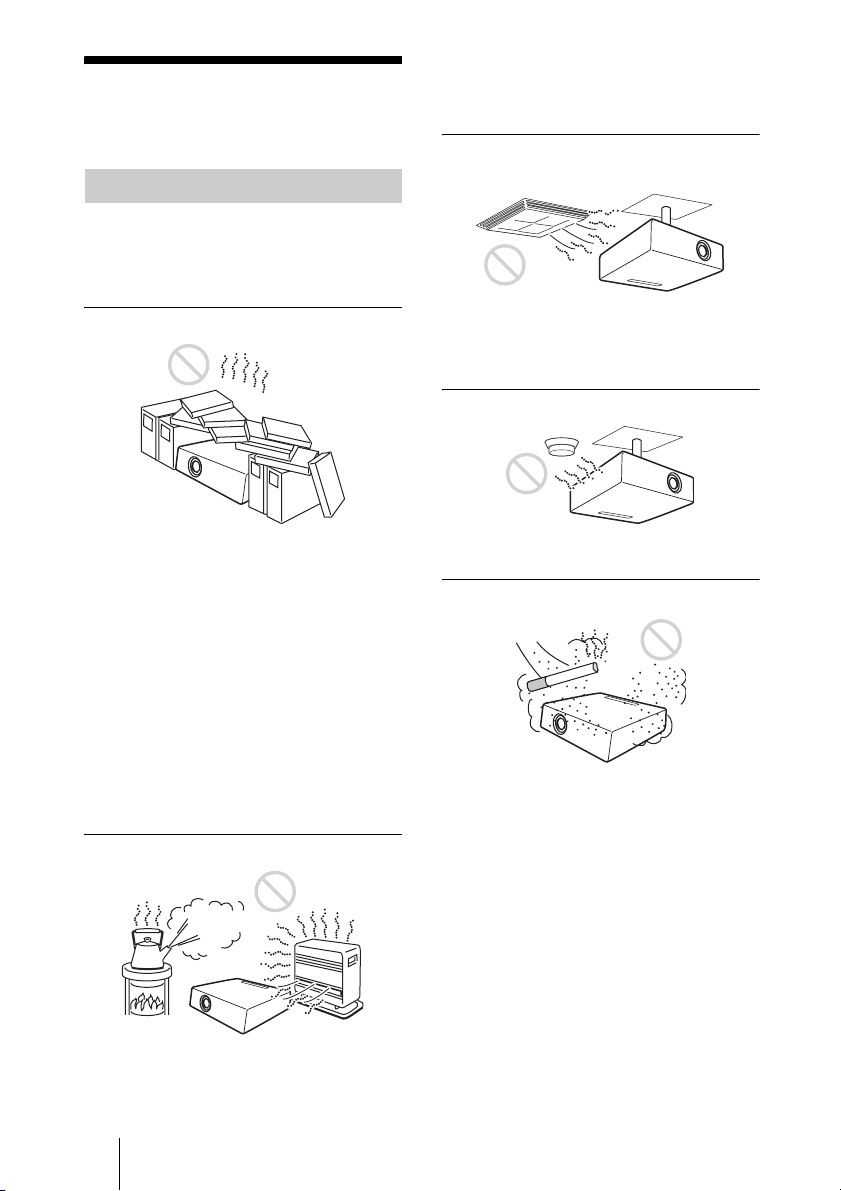
Unsuitable Installation
Do not install the projector in the following
situations. These installations may cause
malfunction or damage to the projector.
• To avoid moisture condensation, do not
install the unit in a location where the
temperature may rise rapidly.
Subject to direct cool or warm air
from an air-conditioner
Poorly ventilated
• Allow adequate air circulation to prevent
internal heat build-up. Do not place the
unit on surfaces (rugs, blankets, etc.) or
near materials (curtains, draperies) that
may block the ventilation holes.
• When the internal heat builds up due to the
block-up, the temperature sensor will
function with the message “High temp.!
Lamp off in 1 min.” The power will be
turned off automatically after one minute.
• Leave space of more than 30 cm (11
inches) around the unit.
• Be careful that the ventilation holes may
inhale tininess such as a piece of paper.
7
/8
Highly heated and humid
Installing in such a location may cause
malfunction of the unit due to moisture
condensation or rise in temperature.
Near a heat or smoke sensor
Malfunction of the sensor may be caused.
Very dusty, extremely smoky
Avoid installing the unit in a very dusty or
extremely smoky environment. Otherwise,
the air filter will become obstructed, and this
may cause a malfunction of the unit or
damage it. Dust preventing the air passing
through the filter may cause a rise in the
internal temperature of the unit. Clean the
filter periodically.
• Avoid installing the unit in a location
where the temperature or humidity is very
high, or temperature is very low.
6 Notes on Installation and Usage
Page 7
Usage in High Altitude
When using the projector at an altitude of
1,500 m or higher, turn on “High
Altitude Mode” in the INSTALL SETTING
menu. Failing to set this mode when using
the projector at high altitudes could have
adverse effects, such as reducing
the reliability of certain components.
Note on the screen
When using a screen with an uneven surface,
stripes pattern may rarely appear on the
screen depending on the distance between
the screen and the projector or the zooming
magnifications. This is not a malfunction of
the projector.
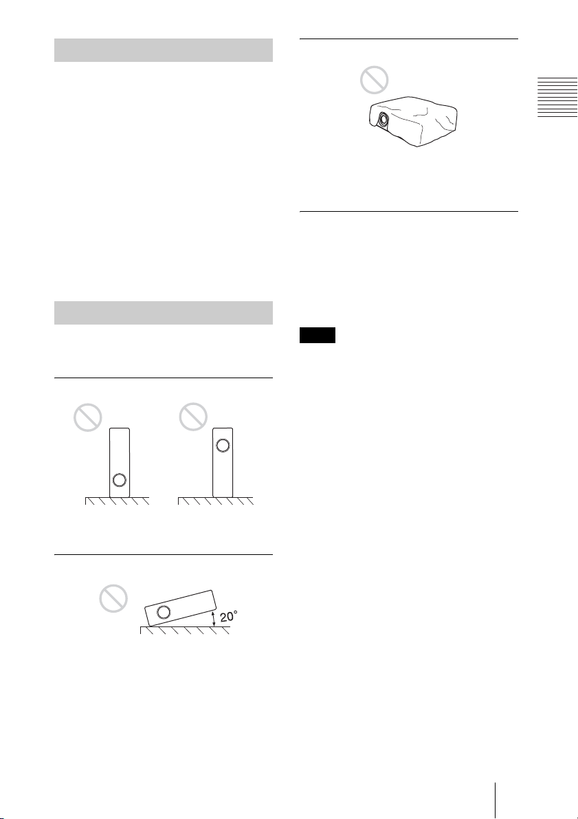
Unsuitable Conditions
Do not use the projector under the following
conditions.
Toppling the unit.
Blocking the ventilation holes
Overview
Avoid using something to cover over the
ventilation holes (exhaust/intake);
otherwise, the internal heat may build up.
Placing a blocking object just in
front of the lens
Do not place any object just in front of the
lens that may block the light during
projection. Heat from the light may damage
the object. Use the PIC MUTING key on the
Remote Commander to cut off the picture.
Note
When using a screen with an uneven surface,
stripes pattern may rarely appear on the screen
depending on the distance between the screen
and the projector or the zooming
magnifications. This is not a malfunction of the
projector.
Avoid using as the unit topples over on its
side. It may cause malfunction.
Tilting right/left
Avoid using as the unit tilts more than 20
degrees. Do not install the unit other than on
the floor or ceiling. These installations may
cause malfunction.
Notes on Installation and Usage
7
Page 8

Features
High brightness, high picture
quality
• High brightness
This projector is equipped with a highefficiency optical system made possible
by adopting Sony’s proprietary optical
system. Because this projector utilizes a
high N.A. LCD panel with a microlens and
a 265W Ultra high pressure lamp, it can
reproduce bright images at 3500 ANSI
lumens.
• High resolution
Three 0.99-inch, about 790,000 pixel,
XGA panels provide a resolution of 1024
× 768 dots for RGB input and 750
horizontal TV lines for video input.
Easy Setup
• Permits setup on a front-to-back slope
This projector can be set up on a slope of
up to 90 degrees up or down. The
projector also permits rear projection
using a mirror.
• Optional lenses
The projector can be adapted to a variety
of different types of installations by using
one of three lenses (sold separately), two
with a short focus and one with a long
focus.
• Direct Power On/Power Off function
The AC power for the entire system can be
turned on and off by means of a breaker or
other switch.
• System expandability using a network
Connection to a LAN allows you to obtain
projector status information such as the
lamp timer or to control the projector away
from the installation location via a Web
browser.
Also, this projector enables the sending of
mail that contains messages on the time for
replacement of the projector lamp, error
occurrences, etc., to mail addresses that
have been specified. This projector
corresponds with SNMP.
8 Features
Convenient presentation functions
• Equipped with USB connector
Simply by connecting the projector to a
computer through the USB interface, the
Remote Commander provided with the
projector can then be used as a wireless
mouse.
Accepts various input signals
• Equipped with DVI connector and
5BNC connector
The projector is equipped with a DVI-D
connector that can be used to connect a
digital RGB device.
The projector is also equipped with a
5BNC input connector that supports highprecision signal connection with a
workstation or other device, as well as
long-distance transmission.
• Scan converter loaded
This projector has a build-in scan
converter that converts the input signal
within 1,024 × 768 dots.
• Compatible input signals
This projector accepts video signals of
composite, S video, and component as
well as VGA, SVGA, XGA, SXGA,
SXGA+ and UXGA (60 Hz) signals,
which all can be displayed. In this
projector, 46 types of input signals are
preset.
• Compatible with six color systems
NTSC, PAL, SECAM, NTSC4.431), PALM, or PAL-N color system can be selected
automatically or manually.
1) NTSC4.43 is the color system used when
playing back a video recorded on NTSC
on a NTSC
...............................................................................
• Windows is a registered trademark of
Microsoft Corporation in the United States
and/or other countries.
• VGA, SVGA, XGA, SXGA and UXGA
are registered trademarks of the
International Business Machines
Corporation, U.S.A.
• Kensington is a registered trademark of
Kensington Technology Group.
• Macintosh is a registered trademark of
Apple Computer, Inc.
• VESA is a registered trademark of Video
Electronics Standard Association.
• Display Data Channel is a trademark of
Video Electronics Standard Association.
4.43 system VCR.
Page 9
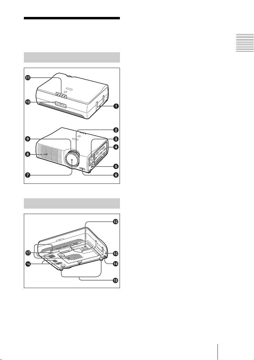
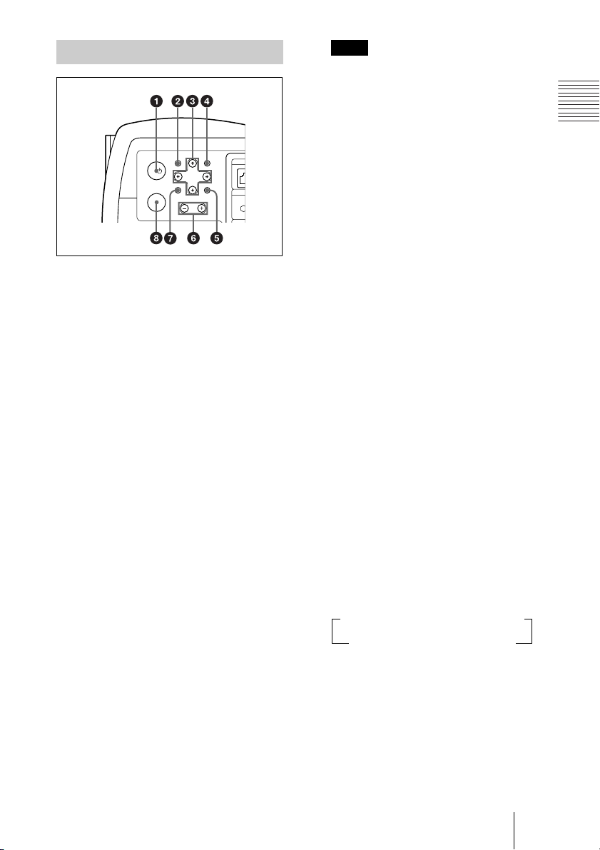
Location and Function of Controls
a Handle
b Zoom ring
Adjusts the picture size.
Front/Left Side
Rear/Right Side/Bottom
c Control panel
For details, see “Control Panel” on
page 11.
d Connector panel
For details, see “Connector Panel” on
page 12.
e AC IN socket
Connects the supplied AC power cord.
f Front remote control detector
g Lens
Remove the lens cap before projection.
h Ventilation holes (exhaust)
i Focus ring
Adjusts the picture focus.
j Rear remote control detector
k Indicators
• LAMP/COVER: Lights up or flashes
under the following conditions:
– Lights up when the lamp has
reached the end of its life or
becomes a high temperature.
– Flashes when the lamp cover or air
filter cover is not secured firmly.
• TEMP (Temperature)/FAN: Lights
up or flashes under the following
conditions:
– Lights up when temperature inside
the projector becomes unusually
high.
– Flashes when the fan is broken.
For details on the LAMP/COVER and
the TEMP/FAN indicators, see on
page 48.
• POWER SAVING: Lights up when
the projector is in power saving mode.
When POWER SAVING in the SET
SETTING menu is set to ON, the
projector goes into power saving mode
if no signal is input for 10 minutes.
Overview
Location and Function of Controls
9
Page 10
Although the lamp goes out, the
cooling fan keeps running. The power
saving mode is canceled when a signal
is input or any key is pressed. In power
saving mode, any key does not
function for the first 60 seconds after
the lamp goes out.
• ON/STANDBY: Lights up or flashes
under the following conditions:
– Lights in red when a AC power cord
is plugged into a wall outlet. Once in
standby mode, you can turn on the
projector with the I / 1 key.
– Lights in green when the power is
turned on.
– Flashes in green while the cooling
fan runs after the power is turned off
with the I / 1 key. The fan runs for
about 90 seconds after the power is
turned off.
The ON/STANDBY indicator
flashes quickly for the first 60
seconds. During this time, you
cannot light up the ON/STANDBY
indicator with the I / 1 key.
Note
To maintain optimal performance, clean
the air filter every 1500 hours.
For details, see “Cleaning the Air
Filter” on page 44.
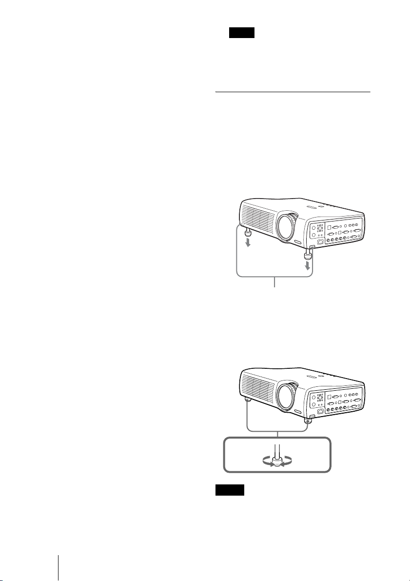
How to use the adjuster
To adjust the height
Adjusts the height of the projector as
follows:
1 Lift the projector and press the
adjuster adjustment buttons.
The adjusters will extend from the
projector.
l Lamp cover
m Security lock
Connects to an optional security cable
(Kensington’s).
Home page address:
http://www.kensington.com/
n Adjuster adjustment buttons
For details, see “How to use the
adjuster” on page 10.
o Adjuster
p Speaker
q Ventilation holes (intake)/air
filter cover
• Do not place anything near the
ventilation holes as it may cause
internal heat build-up.
• Do not place your hand or objects near
the ventilation holes as it may cause the
air coming out heat build-up.
10 Location and Function of Controls
Adjuster adjustment buttons
2 While pressing the buttons, adjust the
projector to the desired height, and
then release the buttons. For fine
adjustment, turn the adjusters to the
right and the left.
to lower
the
projector
Notes
• Be careful not to let the projector down on
your fingers.
• Do not push hard on the top of the projector
with the adjusters out.
It may be occurred malfunction.
to raise the
projector
Page 11
Control Panel
U
H
APAMENU
CONT
I/
VOLUME
INPUT
a I / 1 (on/standby) key
Turns on and off the projector when the
projector is in standby mode. The ON/
STANDBY indicator lights in green
when the power is turned on.
When turning off the power, press
the I / 1 key twice following the
message on the screen, or press and
hold the key for about one second.
For details on steps for turning off the
power, see “To turn off the power” on
page 27.
b MENU key
Displays the on-screen menu. Press
again to clear the menu.
c Arrow keys (M/m/</,)
Used to select the menu or to make
various adjustments.
d APA (Auto Pixel Alignment) key
Pressing this key while a signal from a
computer is being input automatically
adjusts the picture so that it can be seen
clearly. This function also
simultaneously adjusts the screen size
and makes up/down and left/right shift
adjustments.
ET
RESETENTER
INP
Note
Press the APA key when the full image is
displayed on the screen. If the projected
image includes a large black area around
the periphery, the APA function will not
function properly and in some cases,
portions of the image may not be
displayed.
• You can cancel the adjustment by
pressing the APA key again while
“Adjusting” appears on the screen.
• Th e picture may not be adjusted properly
depending on the kinds of input signals.
• Adjust the items “Dot Phase,” “H Size”
and “Shift” in the INPUT SETTING
menu when you adjust the picture
manually.
e RESET key
Resets the value of an item back to its
factory preset value. This key functions
when the menu or a setting item is
displayed on the screen.
f VOLUME +/– key
Adjusts the volume of the built-in
speakers and output level of the AUDIO
jack.
+:Increases the volume.
–: Decreases the volume.
g ENTER key
Enters the settings of items in the menu
system.
h INPUT key
Selects the input signal. Each time you
press the key, the input signal switches
as follows:
t INPUT A t INPUT B t INPUT C t
S VIDEO T VIDEO T INPUT D
The audio signals are common to the
INPUT B, INPUT C, VIDEO and
S-VIDEO.
Overview
Location and Function of Controls
11
Page 12
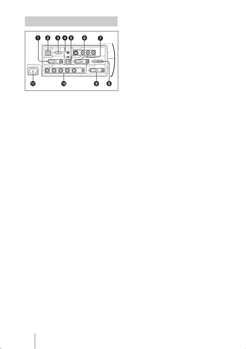
Connector Panel
VOLUME
~AC IN
INPUT D OUTPUT
INPUT A INPUT B INPUT C
NETWORK
(PLUG IN POWER)
(MONO)
LR
RS-232C IN S VIDEO VIDEO AUDIO
RGB AUDIO RGB DVI-D
R/R-Y/Pn G/Y B/B-Y/Ps SYNC/HD VD AUDIO MONITOR AUDIO
AUDIO
ENTERMENU
RESETAPA
CONTROL
REMOTE VIDEO IN
CONTROL S
a INPUT A connectors
Connect to a computer.
• HD D-sub 15-pin, female:
Connect to the monitor output on a
computer using the supplied cable.
• AUDIO (stereo min i-jack): Connects
to the audio output on a computer.
b NETWORK (RJ-45)
Connects to the LAN cable when the
network function is in use.
c RS-232C connector (D-sub 9-
pin, female)
Connects to a computer to operate the
projector from the computer.
d CONTROL S IN/PLUG IN
POWER (DC 5V output) jack
Connects to the control S out jacks of the
Sony equipment. Connects to the
CONTROL S OUT jack on the supplied
Remote Commander when using it as a
wired Remote Commander. In this case,
when a stereo cable is used, you do not
need to install the batteries in the
Remote Commander, since the power is
supplied from this jack.
e USB connector (USB plug for
upstream, 4-pin)
Connects to the USB connector on a
computer. When you connect the
projector to the computer, you can
control the mouse function with the
supplied Remote Commander.
Connect to external video equipment
such as a VCR.
• S VIDEO (mini DIN 4-pin):
Connects to the S video output (Y/C
video output) of video equipment.
• VIDEO (phono type): Connects to
the composite video output of video
equipment.
• AUDIO input L (MONO)/R (phono
type): Connect to the audio output of
equipment. For stereo equipment, use
both the L and R jacks; for monaural
equipment, use the L (MONO) jack
only.
g INPUT B connectors
Connect to a computer.
• HD D-sub 15-pin, female:
Connects to the monitor output on a
computer using the supplied cable.
• AUDIO (stereo mini-jack)/Shared
by INPUT B and C: Connects to the
audio output on a computer.
h INPUT C connector (RGB (DVI))
(DVI-D)
Connects to a computer equipped with
DVI (digital) output connector with a
DVI cable.
i OUTPUT connectors
• MONITOR (HD D-sub 15-pin,
female): Connect to the video input
connector on the monitor. Outputs
signals from the selected channel and
computer signals only from among the
signals from the INPUT A, INPUT B,
or INPUT D RGB connector. This
connector does not output any signals
from the INPUT C connector.
• AUDIO (stereo mini-jack ): Connects
to external active speakers. The
volume of the speakers can be
controlled by the VOLUME +/– keys
on the Remote Commander or the
VOLUME +/– keys on the control
panel.
f Video input connectors
12 Location and Function of Controls
Page 13
j INPUT D connectors
• 5BNC input connectors (R/R-Y/PR,
G/Y, B/B-Y/PB, SYNC/HD, VD
connectors) (BNC type): Connect to
a high-resolution computer or VCR
where signals are transmitted long
distances; for example, when the
projector has been hung from the
ceiling.
According to the connected
equipment, computer, component (RY/Y/B-Y), HDTV or DTV (DTV
GBR, DTV YP
BPR) signal is selected.
• AUDIO (stereo mini-jack ): Connects
to the audio output on a computer.
k AC IN socket
Connects the supplied AC power cord.
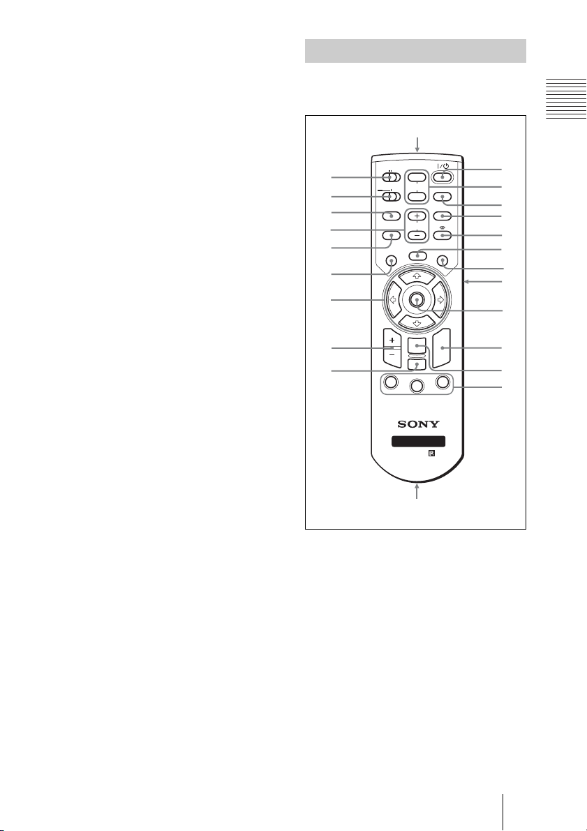
Remote Commander
The keys which have the same names as on
the control panel function identically.
ws
COMMAND
ON
wa
w;
ql
qk
qj
qh
qg
qf
qd
OFF
PJ NETWORK
LENS
APA
MENU/
TAB
D ZOOM
1
PIC
MUTING
AUDIO
TILT/KEYSTONE
VOLUME
FREEZE
ENTER
RESET/
ESCAPE
2
FUNCTION
RM-PJM15
PROJECTOR
RM-PJM17
INPUT
AIR SHOT
R
CLICK
3
1
2
3
4
5
6
7
8
8
8
9
q;
Overview
qa
,
qs
a I / 1 key
b MUTING keys
Cut off the picture and sound.
• PIC: Cuts off the picture. Press again
to restore the picture.
• AUDIO: Press to temporarily cut off
the audio output from the speaker, and
the output on the AUDIO jack in the
OUTPUT section.
Press again or press the VOLUME +
key to restore the sound.
c INPUT key
Location and Function of Controls
13
Page 14

4 TILT/KEYSTONE key
Adjusts the vertical trapezoidal
distortion of the image manually. Use
the arrow keys (M/m/</,) for
adjustment.
e (Memory Stick) key
This function is not provided in this
projector.
f FREEZE key
This key freezes the projected image.
Press again to unfreeze the image.
g AIR SHOT key
This function is not provided in this
projector.
n D ZOOM +/– key
Enlarges the image at a desired location
on the screen.
o Arrow keys (M/m/</,)
p MENU/TAB key
Functions as a MENU key.
q APA (Auto Pixel Alignment) key
Automatically adjusts a picture to its
clearest while a signal is input from a
computer.
For details, see “Smart APA” in the SET
SETTING menu on page 34.
r VOLUME +/– keys
8 Keys that emulate a mouse
These keys function as mouse function
and buttons of a computer only when the
projector is connected to the computer
using the USB cable.
i ENTER key
j FUNCTION 1/2/3 keys
This key does not work in the unit.
k Strap holder
Attaches the supplied strap.
l CONTROL S OUT jack (stereo
mini-jack)
Connects to the CONTROL S IN jack on
the projector with the connecting cable
(not supplied) when using the Remote
Commander as a wired one. In this case,
you do not need to install the batteries
since the power is supplied via the
CONTROL S IN jack on the projector.
m RESET/ESCAPE key
Functions as a RESET key.
Resets the value of an item to its factory
preset value or returns the enlarged
image to its original size. This key
functions when the menu or a setting
item is displayed on the screen.
s LENS key
This function is not provided in this
projector.
t PJ/NETWORK (Projector/
Network) selector switch
Set this switch to PJ always.
u COMMAND ON/OFF switch
When this switch is set to OFF, no key
on the Remote Commander function.
This saves the battery power.
v Infrared transmitter
14 Location and Function of Controls
Page 15
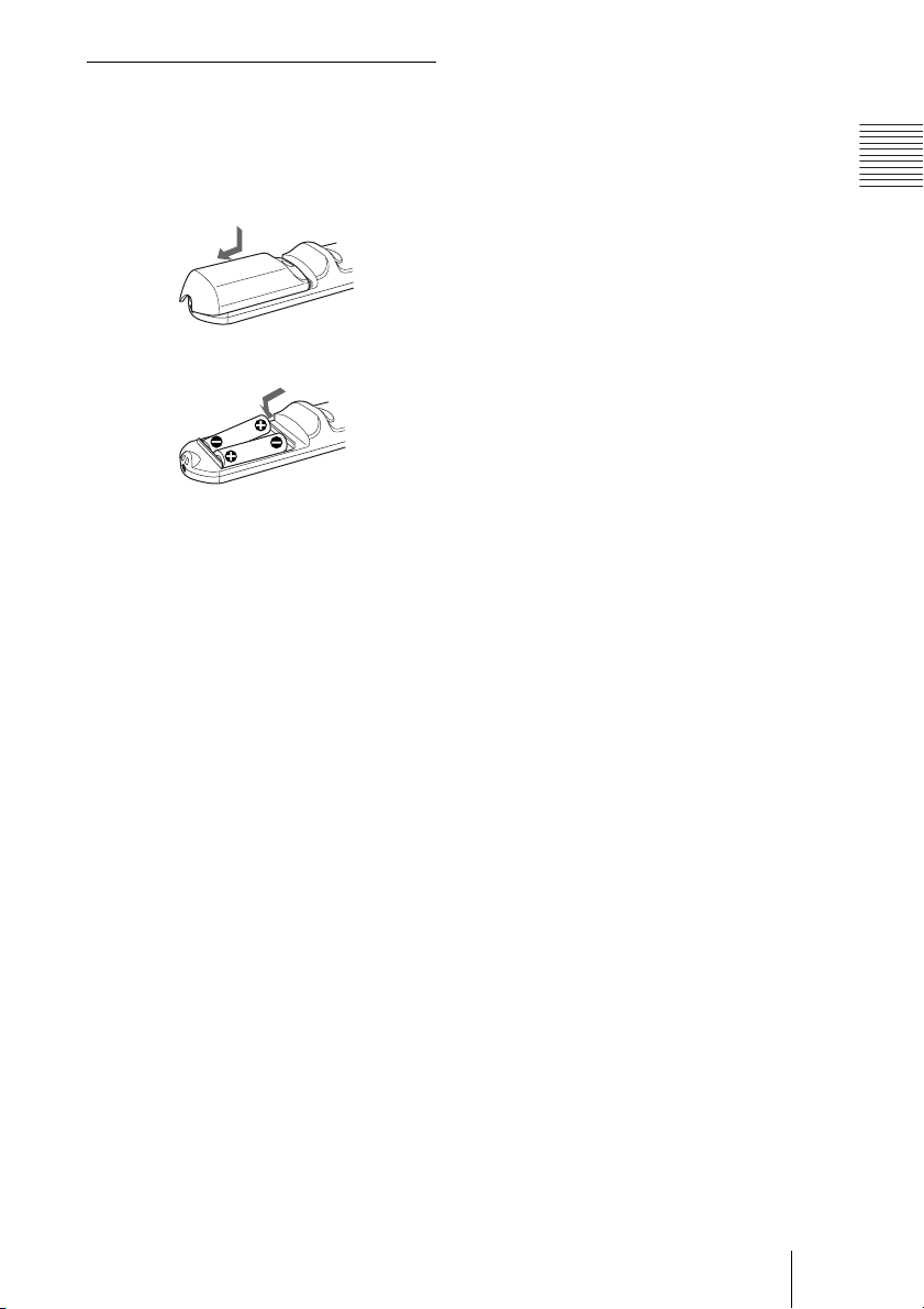
Battery installation
1 Push and slide to open the lid, then
install the two size AA (R6) batteries
(supplied) with the correct polarity.
While pressing the lid, slide it.
Be sure to install the battery
# side.
from the
2 Replace the lid.
Notes on batteries
• Make sure that the battery orientation is
correct when inserting batteries.
• Do not mix an old battery with a new one
or different types of batteries.
• If you will not use the Remote
Commander for a long time, remove the
batteries to avoid damage from battery
leakage. If batteries have leaked, remove
them, wipe and dry the battery
compartment, and replace the batteries
with new ones.
Overview
Notes on Remote Commander
operation
• Make sure that nothing to obstruct the
infrared beam between the Remote
Commander and the remote control
detector on the projector.
• The operation range is limited. The shorter
the distance between the Remote
Commander and the projector is, the wider
the angle within which the commander can
control the projector.
Location and Function of Controls
15
Page 16
B Setting Up and Projecting
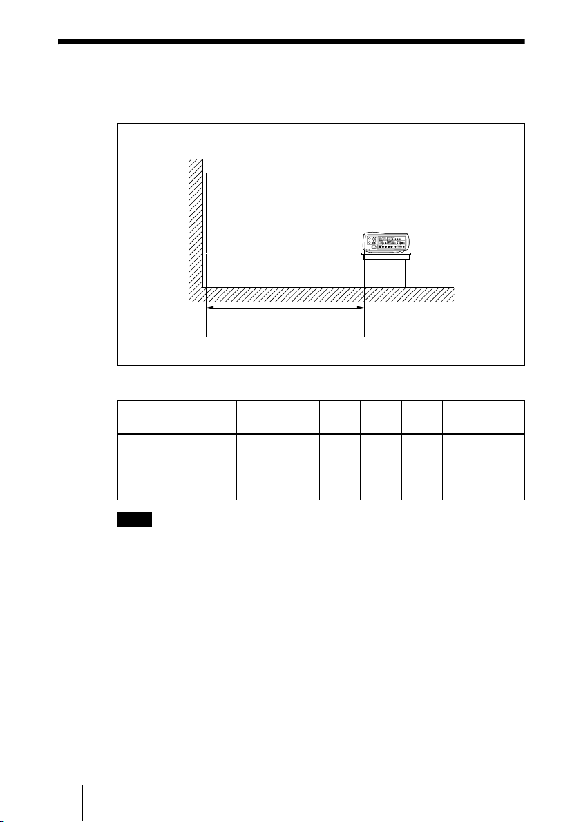
Installing the Projector
This section describes how to install the projector.
The distance between the lens and the screen varies depending on the size of the
screen. Use the following table as a guide.
Distance between the screen and
the center of the lens
Unit: m (ft)
Screen size
(inches)
Minimum
Distance
Maximum
Distance
40 60 80 100 120 150 200 300
1.5
2.3
2.9
3.0
(10.0)
3.8
(12.5)
(4.9)
1.9
(6.2)
(7.5)
(9.5)
3.8
(12.5)
4.8
(15.7)
4.6
(15.0)
5.8
(19.0)
5.8
(19.0)
7.2
(23.6)
7.7
(25.2)
9.7
(31.7)
11.6
(37.9)
14.5
(47.6)
Note
For details on ceiling installation, consult with qualified Sony personnel.
16 Installing the Projector
Page 17

Connecting the Projector
When you connect the projector, make sure to:
• Turn off all equipment before making any connections.
• Use the proper cables for each connection.
• Insert the cable plugs firmly; loose connections may increase noise and
reduce performance of picture signals. When pulling out a cable, be sure to
pull it out from the plug, not the cable itself.
To connect the projector, refer to the illustrations on the next and the
following pages.
Connecting with a Computer
This section describes how to connect the projector to a computer.
For more information, refer to the computer’s instruction manual.
Notes
• The projector accepts VGA, SVGA, XGA, SXGA, SXGA+ and UXGA (60 Hz)
signals. However, we recommend that you set the output mode of your computer to
XGA mode for the external monitor.
• If you set your computer, such as a notebook type, to output the signal to both your
computer’s display and the external monitor, the picture of the projector may not
appear properly. Set your computer to output the signal to only the external monitor.
For details, refer to the computer’s operating instructions supplied with your
computer.
• This projector is compatible with a DDC2B (Digital Data Channel 2B). If your
computer is compatible with a DDC, turn the projector on according to the following
procedures.
1 Connect the projector to the computer by using the supplied HD D-sub 15-pin cable
or DVI cable.
2 Turn the projector on.
3 Start the computer.
Setting Up and Projecting
Connecting the Projector
17
Page 18
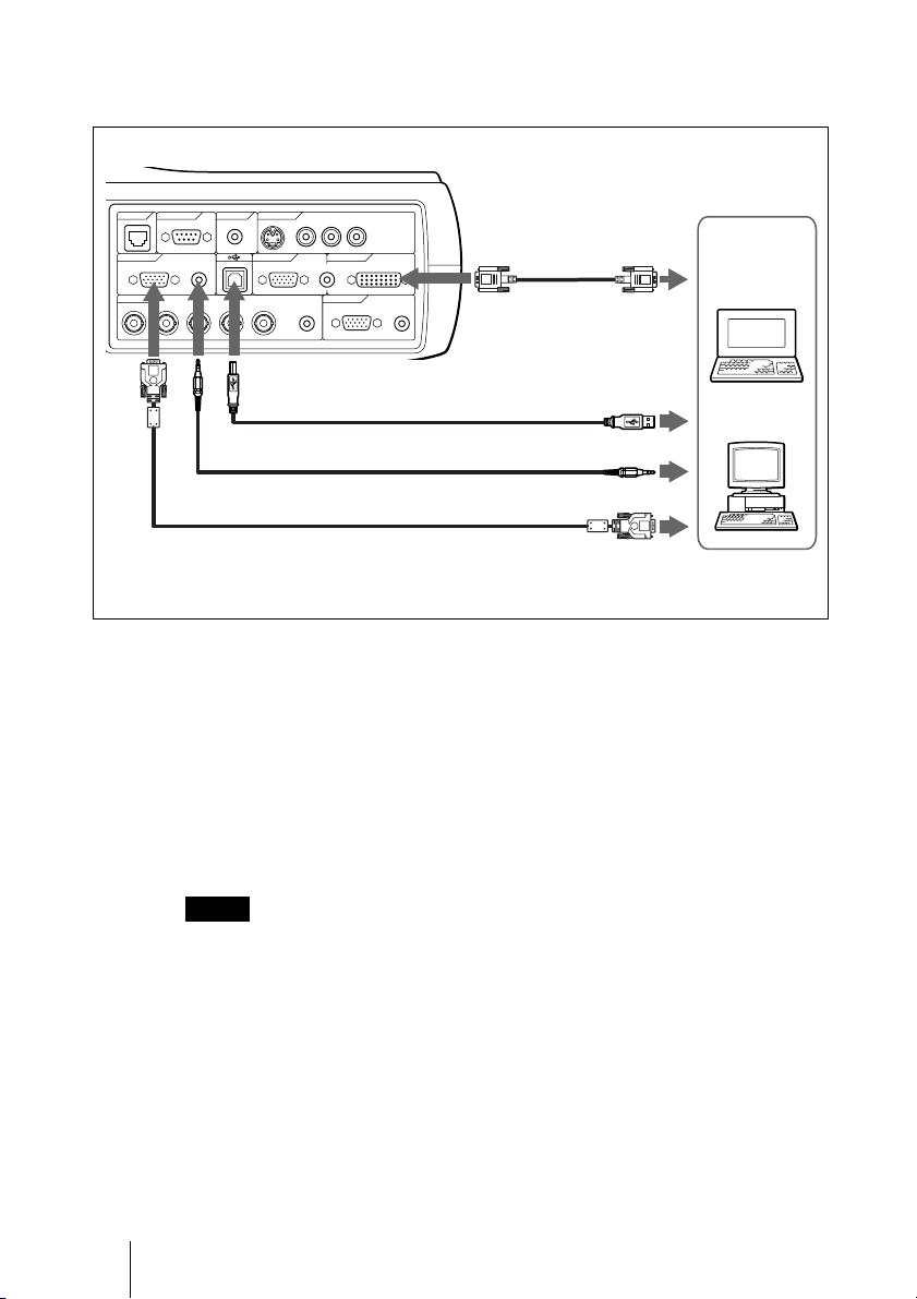
To connect a computer
When you use a wireless mouse
Right side
CONTROL
REMOTE VIDEO IN
NETWORK
INPUT A INPUT B INPUT C
RGB AUDIO RGB DVI-D
INPUT D OUTPUT
R/R-Y/Pn G/Y B/B-Y/Ps SYNC/HD VD AUDIO MONITOR AUDIO
CONTROL S
RS-232C IN S VIDEO VIDEO AUDIO
(PLUG IN POWER)
(MONO)
AUDIO
LR
DVI cable (not
supplied)
b)
To DVI-D
output
Computer
USB cable (supplied)
(Connect the USB cable to use a
wireless mouse.)
Stereo audio connecting cable (not supplied)
HD D-sub 15-pin cable (supplied)
a) Use a no-resistance cable.
b) Connect a DVI cable to use a DVI equipment.
On the USB function
When connecting the projector to a computer by using the USB cable for the
first time, the computer recognizes the following devices automatically.
USB human interface device (wireless mouse function)
Recommended operating environment
When you use the USB function, connect your computer as illustrated above.
The USB mouse function can be used on a computer that came with Windows
98, Windows 98 SE, Windows ME, Windows 2000 or Windows XP
preinstalled models.
Notes
• Your computer may not start correctly when connected to the projector via the USB
cable. In this case, disconnect the USB cable, restart the computer, then connect the
computer to the projector using the USB cable.
• This projector is not guaranteed for suspend, standby mode. When you use the
projector in suspend, standby mode, disconnect the projector from the USB port on
the computer.
• Operations are not guaranteed for all the recommended computer environments.
to USB connector
a)
to audio output
to monitor output
18 Connecting the Projector
Page 19

To connect a Macintosh computer
W
To connect a Macintosh computer equipped with video output connector of a
type having two rows of pins, use a commercially available plug adaptor.
When you connect a USB capable Macintosh computer using the USB cable
to the projector, wireless mouse functions become available.
Connecting with a VCR
This section describes how to connect the projector to a VCR.
For more information, refer to the instruction manuals of the equipment you
are connecting.
Setting Up and Projecting
To connect to a video or S video output connector
Right side
VIDEO IN
S
S VIDEO VIDEO AUDIO
ER)
INPUT B INPUT C
LR
(MONO)
-
Audio connecting cable (not supplied)
Video cable (not supplied) or
S-Video cable (not supplied)
to video output
to S video
For stereo equipment, use both the L and R jacks.
For monaural equipment, use the L (MONO) jack only.
output
to audio
output
VCR
Connecting the Projector
19
Page 20

To connect to a video GBR/Component equipment
Right side
INPUT D OUTPUT
R/R-Y/Pn G/Y B/B-Y/Ps SYNC/HD VD AUDIO MONITOR AUDIO
BNC cable (not supplied)
a) Use a no-resistance cable.
Notes
• When you connect the unit to a video GBR output connector, select video GBR or
component with the Input-D Signal Sel. setting in the SET SETTING menu.
• Use the composite sync signal when you input the external sync signal from video
GBR/component equipment.
Stereo audio connecting cable
(not supplied)
a)
to video
GBR/
component
output
video GBR/Component equipment
to audio
output
20 Connecting the Projector
Page 21

Selecting the Menu Language
You can select one of nine languages for displaying the menu and other onscreen displays. The factory setting is English.
Front remote
COMMAND
ON
OFF
PJ NETWORK
LENS
APA
MENU/
TAB
PIC
MUTING
AUDIO
VOLUME
FREEZE
INPUT
TILT/KEYSTONE
AIR SHOT
2
3
4,5,6
control detector
INPUT
I/
VOLUME
Setting Up and Projecting
APAMENU
RESETENTER
1 Plug the AC power cord into a wall outlet.
2 Press the I / 1 key to turn on the projector.
3 Press the MENU key.
The menu appears.
The menu presently selected is shown as a yellow button.
PICTURE SETTING
Picture Mode:
Adjust Picture...
Volume: 30
Input A
Selecting the Menu Language
21
Page 22

4 Press the M or m key to select the MENU SETTING menu, then press the
, or ENTER key.
The selected menu appears.
Input A
:
:
:
:
A
5 Press the M or m key to select “Language,” then press the , or ENTER
key.
:
:
:
:
Input A
6 Press the M or m key to select a language, then press the < or ENTER
key.
The menu changes to the selected language.
To clear the menu
Press the MENU key.
The menu disappears automatically if a key is not pressed for one minute.
22 Selecting the Menu Language
Page 23

Projecting
COMMAND
ON
OFF
PIC
PJ NETWORK
MUTING
AUDIO
LENS
MENU/
TILT/KEYSTONE
VOLUME
APA
TAB
FREEZE
INPUT
AIR SHOT
Rear remote control
detector
I/
2
4
INPUT
6
LAMP/
COVER
6
TEMP/
FAN
VOLUME
POWER
SAVING
APAMENU
RESETENTER
STANDBY
Setting Up and Projecting
ON/
ON/STANDBY
indicators
1 Plug the AC power cord into a wall outlet, then connect all equipment.
The ON/STANDBY indicator lights in red and the projector goes into
standby mode.
2 Press the I / 1 key.
The ON/STANDBY indicator lights in green.
3 Turn on the equipment connected to the projector.
4 Press the INPUT key to select the input source.
To input from Press INPUT to display
Computer connected to the INPUT A connector INPUT A
Computer connected to the INPUT B connector INPUT B
Computer connected to the INPUT C (digital) connector INPUT C
Computer connected to the INPUT D connector INPUT D
Video equipment connected to the VIDEO input
connector
VIDEO
Projecting
23
Page 24

To input from Press INPUT to display
Video equipment connected to the S VIDEO input
connector
S VIDEO
Smart APA (Auto Pixel Alignment) adjusts the picture of the connected
equipment so that it is projected clearly.
Notes
• If “Auto Input Search” is set to “On”, the projector searches for the signals from
the connected equipment and displays the input channel where the input signals
are found.
For details, see “Auto Input Search” in the SET SETTING menu on page 34.
• The smart APA is effective for the input signal from a computer only.
5 Switch the equipment to be connected to output to the projector.
Depending on the type of your computer, for example a notebook, or an all-inone LCD type, you may have to switch the computer to output to the projector
by pressing certain keys (e.g., , etc.), or by changing your
computer’s settings.
F7
VGA
LCD
,
//
or
Fx
and
Fn
6 Adjust the vertical trapezoidal distortion of the picture with the “V
7 Turn the zoom ring to adjust the size of the picture.
8 Turn the focus ring to adjust the focus.
Attention
Looking into the lens when projecting may cause injury to your eyes.
24 Projecting
Note
The key for switching the computer to output to the projector varies depending on
the type of a computer.
keystone.”
Press the TILT/KEYSTONE key on the Remote Commander to display the V
keystone menu (vertical trapezoidal distortion correction) and adjust the
distortion using the M/m/</, keys.
Page 25

To adjust the volume
The volume can be adjusted in the on-screen menu. See “Volume” in the
PICTURE SETTING menu on page 32.
To mute the picture
Press the PIC MUTING key on the Remote Commander. Press again to restore
the picture.
To control the computer using the supplied Remote Commander
When you connect a computer to the projector by using the USB cable, you
can control the mouse of the computer using the Remote Commander.
The R/L CLICK keys and joystick function as follows.
Note
Make sure that nothing obstructs the infrared beam between the Remote Commander
and the remote control detector on the projector.
Key and joystick Function
R CLICK (front) Right button
L CLICK (rear) Left button
Joystick Corresponds with the movements of the mouse
To get the clearest picture
You can adjust picture quality when projecting a signal from the computer.
1 Project a still picture from the computer.
Setting Up and Projecting
2 Press the APA key.
“Complete!” appears on the screen when the picture is adjusted properly
Notes
• Press the APA key when the full image is displayed on the screen. If the projected
image includes a large black area around the periphery, the APA function will not
function properly and in some cases, portions of the image may not be displayed.
• When you switch the input signal or re-connect a computer, press the APA key again
to adjust the picture again.
• You can cancel the adjustment by pressing the APA key again while “ADJUSTING”
appears on the screen.
• The picture may not be adjusted properly depending on the kinds of input signals.
• Adjust the items in the INPUT SETTING menu when you adjust the picture manually.
Using the security lock
The projector is equipped with a security lock function. When you turn the
power of the projector on, you are required to input the previously set
password. If you do not input the correct password, you will not be able to
project the picture.
Projecting
25
.
Page 26

Note
You will not be able to use the projector if you forget your password and the password
administrator is not available. Be please aware that using the security lock can prevent
valid usage in such cases.
1 Press the MENU key and then, in the INSTALL SETTING menu, turn on
the security lock setting.
2 Enter the password.
Use the MENU,
password. (The default setting is
Next, the screen for entering the new password is displayed. (Enter the
password at this screen even if you want to keep the current password.)
M/m/</,, and ENTER keys to enter the four-digit
“ENTER, ENTER, ENTER, ENTER.”)
Enter password key
Use: Cancel: Other key
3 Enter the password again to confirm.
If “Invalid Password!” is displayed on the menu screen, perform again
from step 1.
INSTALL SETTING
V Keystone: 0
Image Flip: Off
Background: Blue
Lamp Mode: Standard
Direct Power On: Off
High Altitude Mode
Security Lock: Off
: Off
Input A
X
4 Turn the main power off and disconnect the AC power cord.
The security lock is set to on, then it becomes effective. The screen for entering
the password is displayed when the power is turned on the next time.
Security certification
When the screen for entering the password is displayed, enter the password
that was set. If you fail to enter the correct password after three tries, the
projector cannot be used. In this case, press the I /
To cancel the security lock
1 Press the MENU key, then turn off the “Security Lock” setting in the
INSTALL SETTING menu.
26 Projecting
Invalid Password!
1 key to turn off the power.
Page 27

2 Enter the password.
Enter the password that was set.
Note
If you call the customer service center because you have forgotten the password, you
will need to be able to verify the projector’s serial number and your identity. (This
process may differ in other countries.) Once your identity has been confirmed, we will
provide you with the password.
To turn off the power
1 Press the I / 1 key.
“POWER OFF? Please press I / 1 key again.” appears to confirm that you
want to turn off the power.
Note
A message disappears if you press any key except the I / 1 key, or if you do not
press any key for five seconds.
2 Press the I / 1 key again.
The ON/STANDBY indicator flashes in green and the fan continues to run for
about 90 seconds to reduce the internal heat. Also, the ON/STANDBY
indicator flashes quickly for the first 60 seconds. During this time, you will not
be able to light up the ON/STANDBY indicator with the I / 1 key.
3 Unplug the AC power cord from the wall outlet after the fan stops running
and the ON/STANDBY indicator lights in red.
When you cannot confirm the on-screen message
When you cannot confirm the on-screen message in a certain condition, you can
turn off the power by holding the I / 1 key for about one second.
Note
The internal circuitry of the Direct Power On/Off function may cause the fan to continue
to operate for a short time even after the I / 1 key is pressed to turn off the power and
the ON/STANDBY indicator changes to red.
Direct Power On/Off function
If you will be using a circuit breaker to turn the power for the entire system on and off,
set the direct power on function to “On”. When you turn off the power, you can also just
unplug the power cord without pressing the I / 1 key. The internal circuitry will cause
the fan to automatically operate for a certain time even after the power cord is removed.
However, if the unit has been on for less than 15 minutes, the fan might not begin to turn
as a result of inadequate charging. In that case, follow the procedure for turning off the
power as described in “To turn off the power”.
Setting Up and Projecting
On air filter
To maintain optimal performance, clean the air filter every 1500 hours.
We recommend that you clean the air filter whenever you replace the lamp,
even if 1500 hours have not elapsed since the last time the air filter was
cleaned.
Projecting
27
Page 28

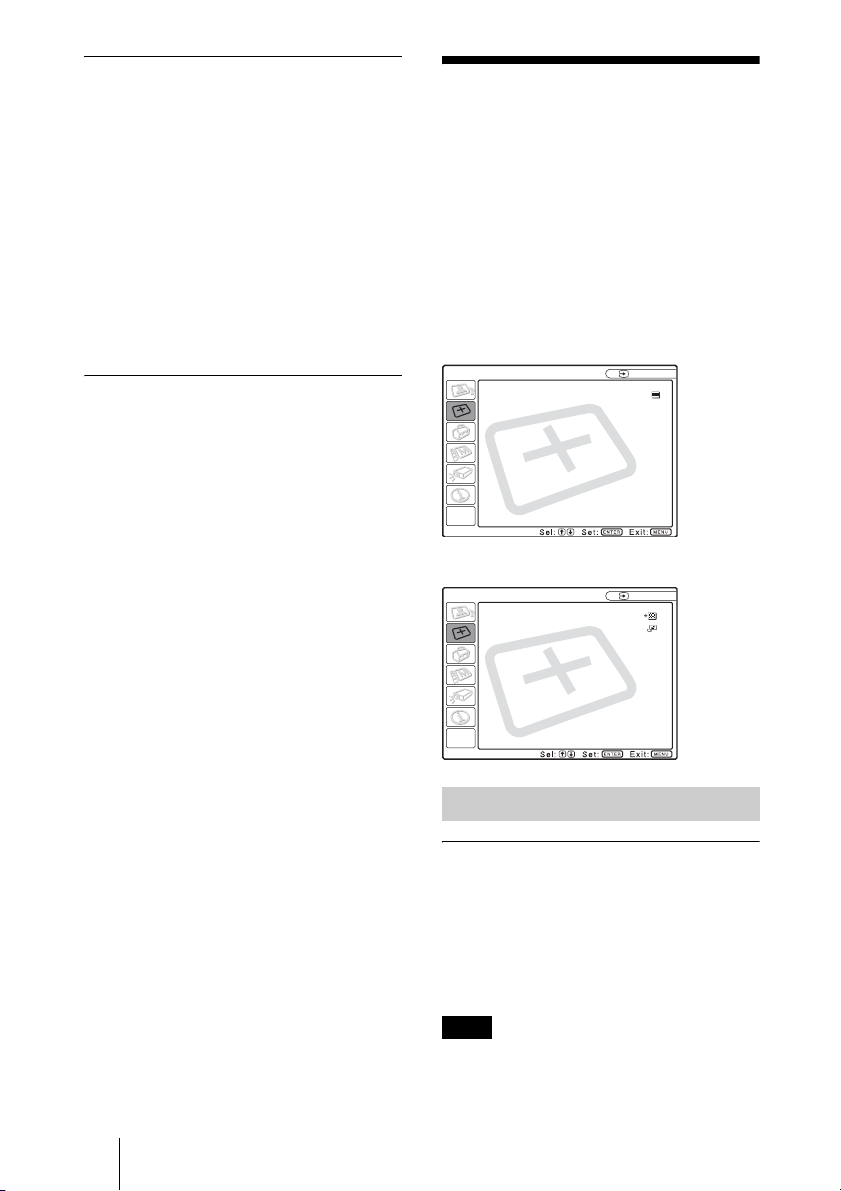
Effective Tools for Your Presentation
To enlarge the image (Digital Zoom function)
You can select a point in the image to enlarge. This function works when a
signal from a computer is input.
1 Press the D ZOOM + key on the Remote Commander.
The digital zoom icon appears the center of the image.
Digital zoom icon
2 Move the icon to the point on the image you want to enlarge. Use the arrow
key (M/m/</,) to move the icon.
3 Press the D ZOOM + key again.
The image where the icon is located is enlarged. The enlargement ratio is
displayed on the screen for a few seconds.
By pressing the + key repeatedly, the image size increases (ratio of
enlargement: max. 4 times.)
Use the arrow key (M/m/</,) to scroll the enlarged image.
To return the image back to its original size
Press the D ZOOM – key.
Just pressing the RESET key returns the image back to its original size
immediately.
To freeze the image projected (Freeze function)
Press the FREEZE key. “FREEZE” appears when the key is pressed. This
function works when a signal from a computer is input.
To restore the original screen, press the FREEZE key again.
28 Projecting
Page 29

B Adjustments and Settings Using the Menu
1 Press the MENU key.
Using the MENU
The projector is equipped with an on-screen
menu for making various adjustments and
settings. The setting items are displayed in a
pop-up menu or in a sub menu. If you select
an item name followed by dots (...), a sub
menu with setting items appear. You can
change the tone of the menu display and the
menu language displayed in the on-screen
menu.
To change the menu language, see
“Selecting the Menu Language” on page 21.
Display items
Input signal indicator
The menu appears.
The menu presently selected is shown as
a yellow button.
SET SETTING
Smart APA:
Auto Input Search:
Input-D Signal Sel:
Color System:
Speaker:
Power Saving:
IR Receiver:
Illumination:
2 Use the M or m key to select a menu,
then press the , or ENTER key.
The selected menu appears.
3 Select an item.
Video
NTSC 4.43
Input signal setting indicator
Picture adjustment menu
Contrast
Input signal indicator
Shows the selected input channel. is
x
displayed when no signal is input. You can
hide this indicator using “Status” in the
MENU SETTING menu.
Use the M or m key to select the item,
then press the , or ENTER key.
The setting items are displayed in a popup menu or in a sub menu.
Pop-up menu
Setting items
Menu
MENU SETTING
Status:
Language:
Menu Position:
Menu Color:
On
Off
Computer
Auto
On
Off
Front&Rear
On
Selected input
signal
Input A
Adjustments and Settings Using the Menu
Input A
Input signal setting indicator
For Input D: Shows “Computer”,
“Component” or “Video GBR”.
Sub menu
Menu Setting items
PICTURE SETTING
ADJUST PICTURE
Contrast: 80
Brightness: 50
RGB Enhancer: 30
Gamma Mode:
Color Temp:
Using the MENU
Standard
Graphics
High
Input A
29
Page 30
4 Make the setting or adjustment on an
item.
• When changing the adjustment level:
To increase the number, press the
, key.
To decrease the number, press the m
or < key.
Press the ENTER key to restore the
previous screen.
• When changing the setting:
Press the M or m key to change the
setting.
Press the ENTER or < key to restore
the previous screen.
To clear the menu
Press the MENU key.
The menu disappears automatically if a key
is not pressed for one minute.
To reset items that have been
adjusted
Press the RESET key on the Remote
Commander.
“Complete!” appears on the screen and the
settings appearing on the screen are reset
to their factory preset values.
Items that can be reset are:
• “Contrast,” “Brightness,” “Color,” “Hue,”
“Sharpness” and “RGB Enhancer” in the
Adjust Picture... menu.
• “Dot Phase,” “H Size,” and “Shift” in the
Adjust Signal... menu.
About the memory of the settings
The settings are automatically stored in the
projector memory.
If no signal is input
If there is no input signal, “Cannot adjust
this item.” appears on the screen.
About the menu display
You can set the display position of the menu,
intensity of the background picture and tone
of the menu items as you like.
For details, see “The MENU SETTING
Menu” on page 35.
M or
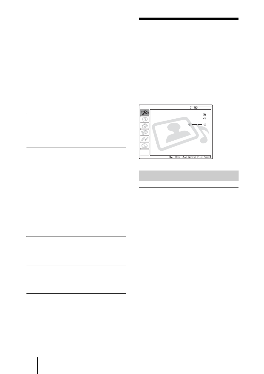
The PICTURE SETTING Menu
The PICTURE SETTING menu is used for
adjusting the picture or volume.
Items that cannot be adjusted depending on
the input signal are not displayed in the
menu.
For details on the unadjustable items, see
page 53.
PICTURE SETTING
Picture Mode Standard
Adjust Picture...
Volume: 30
Menu Items
Picture Mode
Selects the picture mode.
Dynamic: Emphasizes the contrast to
produce a “dynamic” picture.
Standard: Normally select this setting. If
the picture has roughness with the
“Dynamic” setting, this setting reduces
the roughness.
Adjust Picture... Menu Items
The unit can store the setting values of the
following sub menu items for each
“Dynamic” or “Standard” picture mode
separately.
Input A
30 The PICTURE SETTING Menu
Page 31

Adjust Picture...
When the video signal is input
PICTURE SETTING
ADJUST PICTURE
Contrast: 80
Brightness: 50
Color: 50
Hue: 50
Sharpness: 50
Black Level Adj.:
Color Temp.:
DDE: Film
Standard
Off
Low
Video
Sharpness
Adjusts the picture sharpness. The higher
the setting, the sharper the image. The lower
the setting, the softer the image.
RGB Enhancer
Adjusts the picture sharpness when RGB
signals are input.
The higher the setting, the sharper the
picture. The lower the setting, the softer the
picture.
When the RGB signal is input
Graphics
High
Input A
PICTURE SETTING
ADJUST PICTURE
Contrast: 80
Brightness: 50
RGB Enhancer: 30
Gamma Mode:
Color Temp.:
Standard
Contrast
Adjusts the picture contrast. The higher the
setting, the greater the contrast between a
dark portion and a bright portion of the
picture. The lower the setting, the lower the
contrast.
Brightness
Adjusts the picture brightness. The higher
the setting, the brighter the picture. The
lower the setting, the darker the picture.
Color
Adjusts color intensity. The higher the
setting, the greater the intensity. The lower
the setting, the lower the intensity.
Black Level Adj.
Using black level adjustment results in a
vivid image with clearly defined light and
dark areas. Set the black compensation in
accordance with the image source.
High: Strong black compensation
Low: Weak black compensation
Off: No black compensation
Gamma Mode
Selects a gamma correction curve.
Graphics: Improves the reproduction of
halftones. Photos can be reproduced in
natural tones.
Text: Contrasts black and white. Suitable
for images that contain lots of text.
Color Temp.
Adjusts the color temperature.
High: Makes the white color bluish.
Low: Makes the white color reddish.
Adjustments and Settings Using the Menu
Hue
Adjusts color tones. The higher the setting,
the picture becomes greenish. The lower the
setting, the picture becomes purplish.
The PICTURE SETTING Menu
31
Page 32
DDE (Dynamic Detail Enhancer)
Selects the reproduction format of the input
video signals according to the video sources.
Off: Plays back the video signal in an
interlace format without converting.
Progressive: Converts an interlace format
video signal to a progressive format.
Film: Reproduces the 2-2, 2-3 Pull-Down
film sources with smooth picture
movement. When the video signal with a
format other than the 2-2, 2-3 PullDown is input, “Progressive” is
automatically selected.
Volume
Adjusts the volume.
The INPUT SETTING Menu
The INPUT SETTING menu is used to
adjust the input signal.
Items that cannot be adjusted depending on
the input signal are not displayed in the
menu.
For details on the unadjustable items, see
page 53.
When the video signal is input
INPUT SETTING
Wide Mode: Off
When the RGB signal is input
INPUT SETTING
Adjust Signal...
Scan Converter
On
Video
Input A
32 The INPUT SETTING Menu
MENU Items
Wide Mode
Sets the aspect ratio of the picture. When
inputting 16:9 (squeezed) signal from
equipment such as a DVD player, set to On.
Off: When the picture with ratio 4:3 is input.
On: When the picture with ratio 16:9
(squeezed) is input.
Note
Note that if the projector is used for profit or for
public viewing, modifying the original picture
by switching to the wide mode may constitute
Page 33

an infringement of the rights of authors or
producers, which are legally protected.
Adjust Signal... Menu Items
Dot Phase
Adjusts the dot phase of the LCD panel and
the signal output from a computer.
Adjust the picture further for finer picture
after the picture is adjusted by pressing the
APA key.
Adjust the picture to where it looks clearest.
H Size
Adjusts the horizontal size of picture output
from a connector. The higher the setting, the
larger the horizontal size of the picture. The
lower the setting, the smaller the horizontal
size of the picture. Adjust the setting
according to the dots of the input signal.
For details on the suitable value for the
preset signals, see page 55.
Shift
Adjusts the position of the picture. H adjusts
the horizontal position of the picture. V
adjusts the vertical position of the picture.
As the setting for H increases, the picture
moves to the right, and as the setting
decreases, the picture moves to the left.
As the setting for V increases, the picture
moves up, and as the setting decreases, the
picture moves down. Use the < or the ,
key to adjust the horizontal position and the
M and m key for the vertical position.
Scan Converter
Converts the signal to display the picture
according to the screen size.
On: Displays the picture according to the
screen size. The picture will lose some
clarity.
Off: Displays the picture while matching
one pixel of input picture element to that
of the LCD. The picture will be clear but
the picture size will be smaller.
Note
About the Preset Memory No.
This projector has 46 types of preset data for
input signals (the preset memory). When a
preset signal is input, the projector
automatically detects the signal type and
recalls the data for the signal from the preset
memory to adjust it to an optimum picture.
The memory number and signal type of that
signal are displayed in the INFORMATION
menu (See page 36). You can also adjust the
preset data through the INPUT SETTING
menu.
This projecto r has 20 types of user memori es
into which you can save the setting of the
adjusted data for an unpreset input signal.
When an unpreset signal is input for the first
time, a memory number is displayed as 0.
When you adjust the data of the signal in the
INPUT SETTING menu, it will be
registered to the projector. If more than 20
user memories are registered, the newest
memory always overwrites the oldest one.
See the chart on page 55 to find if the signal
is registered to the preset memory.
Since the data is recalled from the preset
memory about the following signals, you
can use these preset data by adjusting “H
Size.” Make fine adjustment by adjusting
“Shift.”
Signal Memory No. SIZE
Super Mac-2 23 1,312
SGI-1 23 1,320
Macintosh 19" 25 1,328
Macintosh 21" 27 1,456
Sony News 36 1,708
PC-9821
1,280 × 1,024
WS Sunmicro 37 1,664
Note
When the aspect ratio of input signal is other
than 4:3, a part of the screen is displayed in
black.
36 1,600
Adjustments and Settings Using the Menu
When XGA, SXGA, SXGA+ or UXGA signal
is input, this item will not be displayed.
The INPUT SETTING Menu
33
Page 34

The SET SETTING Menu
The SET SETTING menu is used for
changing the settings of the projector.
SET SETTING
Smart APA:
Auto Input Search:
Input-D Signal Sel:
Color System:
Speaker:
Power Saving:
IR Receiver:
Illumination:
Menu Items
Smart APA
Activates or deactivates the Smart APA1).
On: Normally select this setting. When a
signal is input from a computer, the APA
functions automatically so that the
picture can be seen clearly. Once the
specified input signal has been adjusted
by the Smart APA, it will not be
readjusted even when the cable is
disconnected and connected again or the
input channel is changed. You can adjust
the picture by pressing APA key on the
Remote Commander even if the Smart
APA set to “On.”
Off: The APA functions when you press the
APA key on the Remote Commander.
1) The APA (Auto Pixel Alignment)
automatically adjusts “Dot Phase,” “H Size”
and “Shift” in the INPUT SETTING menu
for the input signal from a computer.
On
Off
Computer
Auto
On
Off
Front&Rear
On
Input A
Auto Input Search
Normally set to “Off.”
When set to “On,” the projector detects input
signals in the following sequence: Input-A/
Input-B/Input-C/Input-D/Video/S-Video. It
indicates the input channel when the power
is turned on or the INPUT key is pressed.
Input-D Signal Sel.
Selects either a computer signal, a
component signal or a video GBR signal
(15k RGB, DTV, HDTV) for the signal that
is input to the INPUT D connector.
Color System
Selects the color system of the input signal.
If you select “Auto,” the projector detects
the color system of the input signal
automatically. If the picture is distorted or
colorless, select the color system according
to the input signal.
Speaker
Set to “Off” to cut off the sound of the
internal speakers. When set to “Off,”
“Speaker: Off” appears on the screen when
you turn on the power.
Power Saving
When set to “On,” the projector goes into
power saving mode if you do not operate the
unit for 10 minutes with no signal input.
IR Receiver
Selects the remote control detectors (IR
receiver) on the front and rear of the
projector.
Front&Rear: Activates both the front and
rear detectors.
Front: Activates the front detector only.
Rear: Activates the rear detector only.
34 The SET SETTING Menu
Illumination
Selects whether the SONY logo on the top of
the projector lights when the projector is on.
Normally, this setting is “On”. If you want
complete darkness or if the illuminated logo
is a distraction, change this setting to “Off”.
Page 35
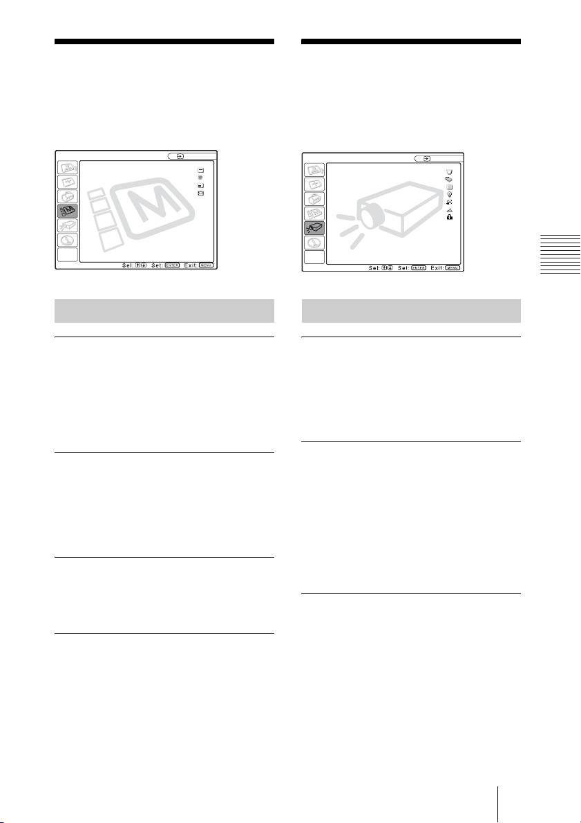
The MENU SETTING Menu
The INSTALL SETTING Menu
The MENU SETTING menu is used for
changing the settings of the projector.
MENU SETTING
Status: On
Language: English
Menu Position: Center
Menu Color: White
Input A
A
Menu Items
Status (on-screen display)
Sets up the on-screen display.
On: Shows all of the on-screen displays.
Off: Turns off the on-screen displays except
for the menus, a message when turning
off the power, and warning messages.
Language
Selects the language used in the menu and
on-screen displays. Available languages are:
English, Français, Deutsch, Italiano,
Español, Português, Japanese, Chinese and
Korean.
Menu Position
Selects the display position of the menu
from Top Left, Bottom Left, Center, Top
Right and Bottom Right.
Menu Color
Selects the tone of the menu display from
Black or White.
The INSTALL SETTING menu is used for
changing the settings of the projector.
INSTALL SETTING
V Keystone: 0
Image Flip: Off
Background: Blue
Lamp Mode: Standard
Direct Power On: Off
High Altitude Mode
Security Lock: Off
: Off
Input A
Menu Items
V Keystone
Corrects the trapezoid caused by the
projection angle. If the base edge is longer,
set a negative value; if the upper edge is
longer, set a positive value to square the
image.
Image Flip
Flips the image on the screen horizontally
and/or vertically.
Off: The image does not flip.
HV: Flips the image horizontally and
vertically.
H: Flips the image horizontally.
V: Flips the image vertically.
Background
Select the background color of the screen
when no signal is input to the projector.
Select Black or Blue.
Normally set to “Blue.”
Adjustments and Settings Using the Menu
The MENU SETTING Menu / The INSTALL SETTING Menu
35
Page 36

Lamp Mode
Sets the lamp brightness in the projection.
High:Illuminates the projected image
brightly.
Standard:Reduces fan noise and power
consumption. The brightness of the
projected image will be lower compared
with the “High” setting.
Direct Power On/Off function
If you will be using a circuit breaker to turn the
power for the entire system on and off, set the
direct power on function to “On”. When you
turn off the power, you can also just unplug the
power cord without pressing the I / 1 key.
High Altitude Mode
Off: Use this setting when using the projector
at normal altitudes.
On: Use this setting when using the projector
at an altitude of 1,500 m or higher.
Security Lock
Turns on the projector’s security lock
function.
Off: Turns off the security lock function.
On: Turns on the security lock function,
which locks the projector once a
password has been set.
For details, see “Using the security
lock” on page 25.
The INFORMATION Menu
The INFORMATION menu displays the
horizontal and vertical frequencies of the
input signal and the used time of the lamp.
INFORMATION
fH: 48.47 kHz
fV: 60.00 Hz
No.23
1024x768
Lamp Timer: 4 H
IP Address: 192.168. 0. 1
Subnet Mask: 255.255. 0. 0
Menu Items
fH
Displays the horizontal frequency of the
input signal.
The displayed value is approximate.
fV
Displays the vertical frequency of the input
signal.
The displayed value is approximate.
Lamp Timer
Indicates how long the lamp has been turned
on.
Input A
Memory
number of
a input
signal
Signal
type
36 The INFORMATION Menu
IP Address
Displays the IP address that is set for the
projector.
Subnet Mask
Displays the subnet mask that is set for the
projector.
Note
These only display on the screen.
Page 37

B Operation and Administration using a Network
Accessing the Projector from a Computer
You can check the present status of the
projector on a computer display and control
the projector from a computer. Also, the
projector enables the sending of mail that
contains messages on the time for
replacement of the projector lamp, error
occurrences, etc., to mail addresses that have
been specified.
Before operating
Confirm that the projector is connected to
the LAN, then turn on the projector. For
details on connection, consult with your
network administrator.
1 Start Internet Explorer 5.0 (or later
versions) on your computer.
2 Type “http://xxx.xxx.xxx.xxx (the IP
address of the projector)” as the
“Address,” then press the ENTER
key.
Checking the Status of the Projector
Click “Information.”
You can check the information and present
status of the projector on a computer display.
You can check the information and status in
the window, but you cannot change the
settings.
Operation and Administration using a Network
You can confirm the IP address of the
projector in the “Information menu” on
page 36.
note
When you access the projector via a Web
browser, do not use a proxy server.
Enter the IP address here.
INFORMATION
The present status of the projector is
displayed.
MENU
The present settings of the projector are
displayed.
Accessing the Projector from a Computer / Checking the Status of the Projector
37
Page 38

Controlling the
Projector from a
Setting Up the Projector
Computer
Click “Control.”
You can perform various adjustments and
settings of the projector on a computer
display.
The function of the buttons in the windows
are the same as those on the remote control
supplied with the projector.
The present setting status is indicated
If you change the setting using the remote
control, click “Refresh” in the upper righthand corner of the window to update the
status.
Click “Setup.”
The Password Properties dialog box
appears.
The name of the “User” account is preset
without a password to “root” at the factory.
You can set the owner information, date and
time, Mail Report, etc.
Click “Apply” in the lower part of each
window to update the projector to the data
input in each window.
Owner information
This information is used for the Mail Report
function.
Owner
Enter owner information.
Projector
Enter the location and lens type of the
projector.
38 Controlling the Projector from a Computer / Setting Up the Projector
Page 39
Memo
Enter a memo, if required.
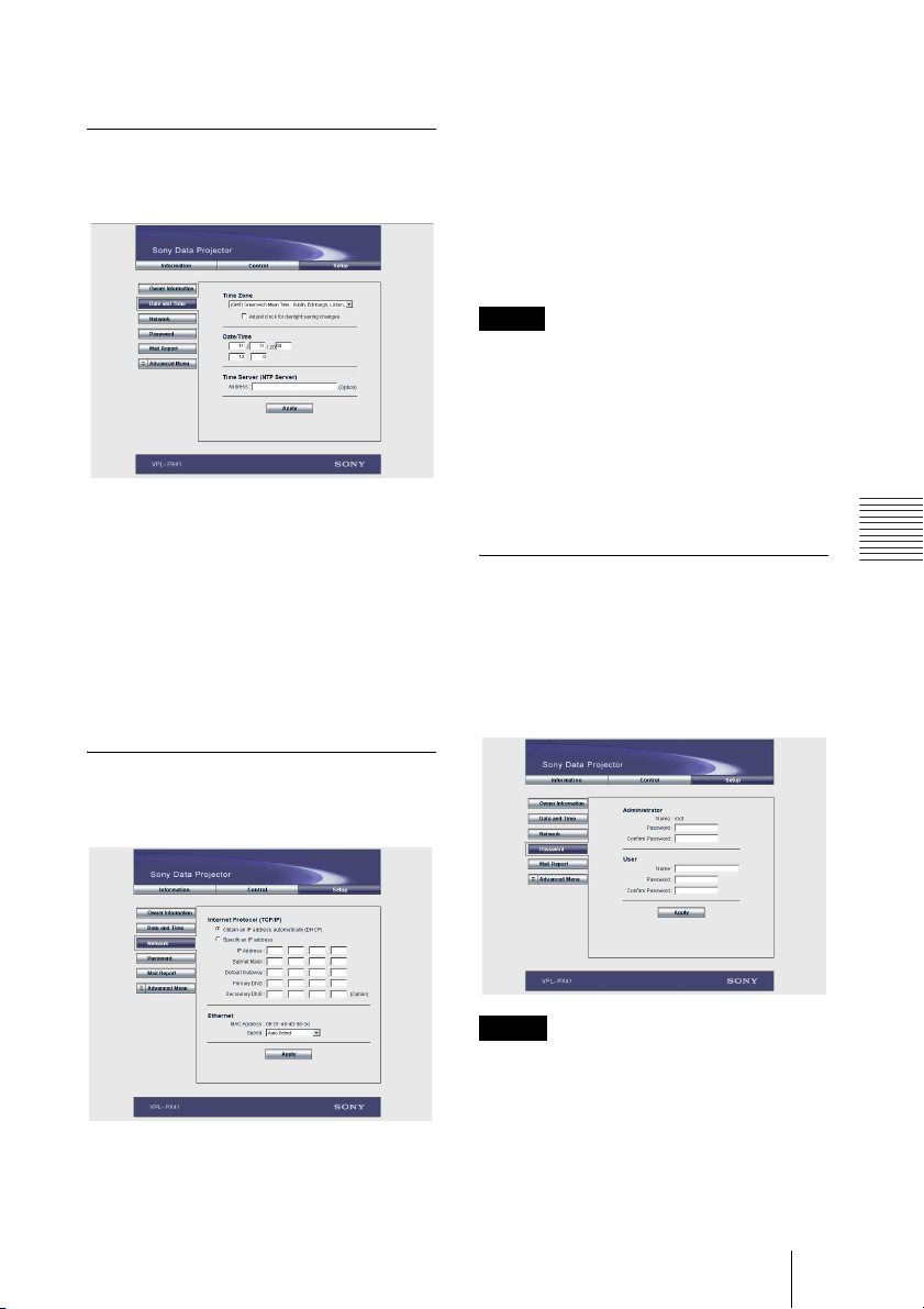
Setting the date and time
This setting is required for the Regular
Report function.
Time Zone
Select the region in which you are using the
projector.
Date/Time
Set the date and time.
Time Server
Enter the address of the time server when the
time is set by a timer server.
Internet Protocol (TCP/IP)
Normally, set “Obtain an IP address
automatically (DHCP).” If you select
“Specify an IP address,” set the necessary
items.
Ethernet
Select the communication speed or
communication mode from the drop-down
list. (Normally set to Auto.)
Notes
• If the IP address is changed, you will not be
able to access the network using an old IP
address.
• To reset the settings of an item back to its
factory settings, press the RESET, ENTER,
m and ENTER keys on the control panel in
order within 5 seconds with the power on,
and reset the settings depending on the
messages displayed on the screen.
Setting passwords for
“Administrator” and “User”
You can set passwords for each
“Administrator” and “User.”
The name of the “Administrator” account is
preset to “root” at the factory. It cannot be
changed.
Operation and Administration using a Network
Network Settings
Enter the information for the network
settings.
Notes
• When you change the password, input a new
password after deleting the password
(*****) that was set.
• If you forget your password, consult with
qualified Sony personnel.
Setting Up the Projector
39
Page 40
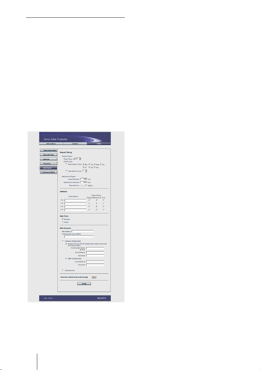
Settings for the Mail Report
function
You can do the following with the Mail
Report function.
• Periodically report the installation status
of the projector, owner information, etc.
You can specify the transmission days and
times of e-mail messages (Regular report).
• Immediately report if any error occurs
with the projector (Error Report).
• Send warning e-mail messages when a
preset time for use of the projector lamp
has been reached (Lamp Reminder).
• Send warning e-mail messages when a
preset time for maintenance of the
projector has been reached (Maintenance
Reminder).
Report Timing field
Regular Report
A report on the present status of the
projector, installation status, etc. of the
projector is periodically sent by e-mail.
Set the timing for sending the e-mail
messages as follows:
AT: Specify the time when e-mail is to be
sent. Select the hour from the drop-down
list.
Every Week on Days: Select this check box
to send e-mail on the selected days every
week.
Mon/Tue/Wed/Thu/Fri/Sat/Sun: Specify
the days of the week when e-mail is to be
sent. You can check two or more days.
Every Month on Day: Select this check box
and select the day from the drop-down
list to send e-mail on a pre-defined day
every month. The Regular Report
contains the product information, owner
information, usage information (time)
for the projector, lamp mode, memos,
etc.
Maintenance Report
Lamp Reminder: Select this check box and
enter the limit for the number of hours
the projector lamp is to be used in the
text box. This information will be used
to send e-mail informing you that
replacement is required for the projector
lamp when the preset time has been
reached. You can specify a time between
1 and 9999 hours.
Maintenance Reminder: Select this check
box and enter the hours of use before
maintenance is required for the projector
in the text box. You can specify a time
between 1 and 99999 hours.
The elapsed time is displayed in the
Elapsed Hours text box. Selecting the
RESET and clicking “Apply” will reset
the elapsed time to zero.
40 Setting Up the Projector
Address field
E-mail Address
Enter the e-mail addresses to which you
want the e-mail messages to be sent in each
text box. The projector allows you to send e-
Page 41

mail to 4 different addresses. You can enter
up to 64 characters for each address.
Report Timing
Regular: Select this check box to arrange
the sending of the Regular Report.
Maintenance: Select this check box to
arrange the sending of an e-mail
message that informs you of the number
of hours the projector lamp has been
used and the time when maintenance is
required for the projector.
Error: Select this check box to arrange the
sending of an error report if any problem
occurs with the projector.
Notes
• Even if days are specified in the Report
Timing field, you still must select the
Regular check box to receive the Regular
Report. If the day preset in “Every Month on
Day” does not exist in the month, you will
receive the e-mail message on the last day of
the month.
• You cannot specify the day of the week or
day of the month if “Every Week on Days”
or “Every Month on Day” is not selected.
Mail Form field
Select the e-mail message type from
“Standard” or “Simple.”
Mail Account field
Mail Address
Type the appropriate e-mail address. You
can enter up to 64 characters.
Outgoing Mail Server (SMTP)
Type the address of the SMTP server. You
can enter up to 64 characters.
Requires Authentication
Select this check box when the
authentication is required for sending an email.
Requires the use of POP Authentication
before send e-mail (POP before
SMTP): Select this check box to arrange
for POP authentication to be performed
before connecting to the SMTP server.
Incoming Mail Server (POP3): Type the
address of the POP3 server.
Account Name: Type the mail account.
Password: Type the mail password.
SMTP Authentication: Select this check
box to arrange for SMTP Authentication
to be performed before connecting the
SMTP server.
Account Name: Type the mail account.
Password: Type the mail password.
Send test mail: Select the Send check box,
then click “Apply” to send an e-mail
message as a test to confirm whether it is
sent to the specified addresses.
Notes
If the following items have not been set or are
incorrectly set, an error message appears and
the test e-mail message is disabled:
• Address in the Address field.
• “Mail Address” and “Outgoing Mail Server
(SMTP)” in the Mail Account field.
For details on the mail settings, consult your
network administrator.
Check the contents of the e-mail
The contents of the e-mail message to be
sent appear.
Advanced setting
Click “Advanced Menu” to display the
Advertisement button, PJ Talk button and
SNMP button. These settings are mainly for
administrative use. For details, consult with
qualified Sony personnel.
Note
You cannot use the following characters to
enter the characters in the text box: “ ' ”, “ " ”,
“\”, “&”, “<”, “>”
Operation and Administration using a Network
Setting Up the Projector
41
Page 42

B Maintenance
Replacing the Lamp
When the lamp has burnt out or dims, or
“Please replace the LAMP.” appears on the
screen, replace the lamp with a new one. Use
LMP-P260 Projector Lamp as the
replacement lamp. The lamp life varies
depending on conditions of use.
Caution
The lamp becomes a high temperature after
turning off the projector with the I / 1 key. If
you touch the lamp, you may scald your
finger. When you replace the lamp, wait for
at least an hour for the lamp to cool.
Notes
• If the lamp breaks, consult with qualified
Sony personnel.
• Pull out the lamp by holding the handle. If
you touch the lamp, you may be burned or
injured.
• When removing the lamp, make sure it
remains horizontal, then pull straight up. Do
not tilt the lamp. If you pull out the lamp
while tilted and if the lamp is broken, the
pieces may scatter, causing injury.
3 Open the lamp cover by loosening a
screw with the Phillips screwdriver.
Note
For safety sake, do not loosen any other
screws.
4 Loosen the three screws on the lamp
unit with the Phillips screwdriver. Pull
out the lamp unit by the handle.
Handle
1 Turn off the projector, and disconnect
the AC power cord from the AC
outlet.
Note
When replacing the lamp after using the
projector, wait for at least an hour for the
lamp to cool.
2 Place a protective sheet (cloth)
beneath the projector. Turn the
projector over so you can see its
underside.
Note
Be sure that the projector is stable after
turning it over.
42 Replacing the Lamp
Note
The screws have washers. Do not remove
the screws, just loosen them.
Page 43

5 Insert the new lamp all the way in until
it is securely in place. Tighten the
screws. Fold up the handle.
Notes
• Be careful not to touch the glass surface
of the lamp.
• The power will not turn on if the lamp is
not secured properly.
6 Close the lamp cover and tighten the
screws.
Note
Do not tighten the screws too much. Doing
so could damage some of the internal
components of the projector.
Disposal of the used lamp
For the customers in the USA
This product contains mercury. Disposal of
this product may be regulated if sold in the
United States. For disposal or recycling
information, please contact your local
authorities or Electronics Industries Alliance
(http://www.eiae.org).
Maintenance
7 Turn the projector back over.
8 Connect the power cord and turn the
projector to standby mode.
9 Press the following keys on the
control panel in the following
sequence for less than five seconds
each: RESET, <, ,, ENTER.
Caution
Do not put your hands into the lamp
replacement spot, or not fall any liquid or
object into it to avoid electrical shock or fire.
Replacing the Lamp
43
Page 44
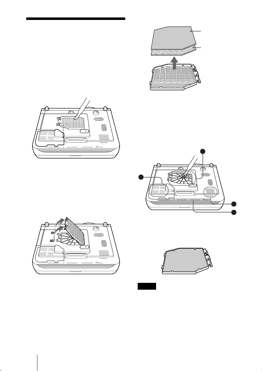
Cleaning the Air Filter
The air filter should be cleaned every 1500
hours.
Remove dust from the outside of the
ventilation holes with a vacuum cleaner.
1500 hours are approximate. This value
varies depending on the environment or how
the projector is used.
When it becomes difficult to remove the dust
from the filter with a vacuum cleaner,
remove the air filter and wash it.
1 Turn off the power and unplug the
power cord.
2 Remove the air filter cover.
3 Remove the air filter.
Small filter
holes
Large
filter holes
4 Wash the air filter with a mild
detergent solution and dry it in a
shaded place.
5 The openings on the bottom of the
projector (A~D) should also be
cleaned with a vacuum cleaner.
D
C
A
B
44 Cleaning the Air Filter
6 Insert the air filter into the four tabs of
the air filter cover, and then attach the
air filter cover to the projector.
Notes
• If you neglect to clean the air filter, dust may
accumulate, clogging it. As a result, the
temperature may rise inside the unit, leading
to a possible malfunction or fire.
• If the dust cannot be removed from the air
filter, replace the air filter with the supplied
new one.
Page 45

• Be sure to attach the air filter cover firmly;
the power will not be turned on if it is not
closed securely.
• The air filter has a face and a reverse side.
The side of the filter with the larger filter
holes should face the outside.
Maintenance
Cleaning the Air Filter
45
Page 46

Troubleshooting
If the projector appears to be operating erratically, try to diagnose and correct the problem
using the following instructions. If the problem persists, consult with qualified Sony personnel.
Power
Symptom Cause and Remedy
The power is not turned on. • The power has been turned off and on with the I / 1 key at a short
Both the LAMP/COVER
and TEMP/FAN indicators
light up.
Picture
Symptom Cause and Remedy
No picture. • Cable is disconnected or the connections are wrong.
The picture is noisy. • Noise may appear on the background depending on the
The picture from INPUT D
connector is colored
strange.
interval.
c Wait for about 60 seconds before turning on the power
(see page 27).
• The lamp cover is detached.
c Close the lamp cover securely (see page 42).
• The air filter cover is detached.
c Close the air filter cover securely (see page 44).
• The electrical system breaks down.
c Consult with qualified Sony personnel.
c Check that the proper connections have been made
(see page 17).
• Input selection is incorrect.
c Select the input source correctly using the INPUT key
(see page 23).
• The picture is muting.
c Press the PIC MUTING key to release the muting function
(see page 25).
• The computer signal is not set to output to an external monitor or
set to output both to an external monitor and a LCD monitor of a
computer.
c Set the computer signal to output only to an external monitor.
c Depending on the type of your computer, for example a
notebook, or an all-in-one LCD type, you may have to switch
the computer to output to the projector by pressing certain keys
or by changing your computer’s settings.
For details, refer to the computer’s operating instructions
supplied with your computer.
combination of the numbers of dot input from the connector and
numbers of pixel on the LCD panel.
c Change the desktop pattern on the connected computer.
• Setting for Input-D Signal Sel. in the SET SETTING menu is
incorrect.
c Select Computer, Video GBR or Component for Input-D Signal
Sel. in the SET SETTING menu according to the input signal
(see page 34).
46 Troubleshooting
Page 47

Symptom Cause and Remedy
“Please check INPUT-D
setting.” appears in spite of
inputting the correct signal
from INPUT D.
On-screen display does not
appear.
Color balance is incorrect. • Picture has not been adjusted properly.
The picture is too dark. • Contrast or Brightness has not been adjusted properly.
The picture is not clear. • Picture is out of focus.
The image extends beyond
the screen.
The picture flickers. • Dot Phase in the INPUT SETTING menu has not been adjusted
• Setting for Input-D Signal Sel. in the SET SETTING menu is
incorrect.
c Select Computer, Video GBR or Component for Input-D Signal
Sel. in the SET SETTING menu according to the input signal
(see page 34).
• Status in the MENU SETTING menu has been set to Off.
c Set Status in the MENU SETTING menu to On (see page 35).
c Adjust the picture (see page 31).
• Projector is set to wrong color system.
c Set Color System in the SET SETTING menu to match the color
system being input (see page 34).
c Adjust the Contrast or Brightness in the PICTURE SETTING
menu properly (see page 31).
• The lamp has burnt or dims.
c Replace the lamp with a new one (see page 42).
c Adjust the focus (see page 24).
• Condensation has occurred on the lens.
c Leave the projector for about two hours with the power on.
• The APA key is pressed although there are black edges around the
image.
c Display the full image on the screen and press the APA key.
c Adjust Shift in the INPUT SETTING menu properly (see
page 33 ).
properly.
c Adjust Dot Phase in the INPUT SETTING menu properly
(page 33).
Maintenance
Sound
Symptom Cause and Remedy
No sound. • Cable is disconnected or the connections are wrong.
When sound is input
through AUDIO connector,
sound comes through one
channel only.
c Check that the proper connections have been made (see
page 17).
• The audio connecting cable is incorrect.
c Use a no-resistance stereo audio cable (see page 18).
• The sound is not adjusted properly.
c Adjust the sound (see page 25).
• The audio is muted.
c Press the AUDIO MUTING key to cancel muting.
• Monaural sound is being input through the AUDIO connector.
c Input stereo sound.
Troubleshooting
47
Page 48

Remote Commander
Symptom Cause and Remedy
The Remote Commander
does not work.
The menu display does not
appear even when you
press the MENU key on the
Remote Commander.
• The Remote Commander batteries are dead.
c Replace with a new battery (see page 15).
• The PJ/NETWORK select switch on the Remote Commander is
set to NETWORK.
c Set the PJ/NETWORK select switch to PJ, then press the
MENU key.
Indicators
Symptom Cause and Remedy
The LAMP/COVER
indicator flashes.
The LAMP/COVER
indicator lights up.
The TEMP/FAN indicator
flashes.
The TEMP/FAN indicator
lights up.
Both the LAMP/COVER
and TEMP/FAN indicators
light up.
• The lamp cover or the air filter cover is detached.
c Attach the cover securely (see page 42).
• The lamp has reached the end of its life.
c Replace the lamp (see page 42).
• The lamp becomes a high temperature.
c Wait for 90 seconds to cool down the lamp and turn on the
power again (see page 27).
• The electrical system breaks down.
c Consult with qualified Sony personnel.
• The fan is broken.
c Consult with qualified Sony personnel.
• The internal temperature is unusually high.
c Check to see if nothing is blocking the ventilation holes.
• The electrical system breaks down.
c Consult with qualified Sony personnel.
Messages List
Warning Messages
Use the list below to check the meaning of the messages displayed on the screen.
Message Meaning and Remedy
High temp.!
Lamp off in 1 min.
Frequency is out of range! • This input signal cannot be projected as the frequency is out of the
Please check INPUT-D
setting.
48 Troubleshooting
• Internal temperature is too high.
c Turn off the power.
c Check to see if nothing is blocking the ventilation holes.
acceptable range of the projector.
c Input a signal that is within the range of the frequency.
• The resolution setting of the output signal of a computer is too
high.
c Set the setting of output to XGA (see page 17).
• You have input RGB signal from the computer when Input-D
Signal Sel. in the SET SETTING menu is set to Component.
c Set Input-D Signal Sel. correctly (see page 34).
Page 49

Message Meaning and Remedy
Please replace the LAMP. • It is time to replace the lamp.
c Replace the lamp.
Caution Messages
Use the list below to check the meaning of the messages displayed on the screen.
Message Meaning and Remedy
No Input • No input signal
c Check connections (see page 17).
Not applicable! • You have pressed the wrong key.
c Press the appropriate key.
Maintenance
Troubleshooting
49
Page 50

B Others
Specifications
Optical characteristics
Projection system
LCD panel 0.99-inch TFT SONY LCD panel
Lens 1.3 times zoom lens
Lamp 265 W Ultra high pressure lamp
Projection picture size
Light output ANSI lumen
Throwing distance (Floor Installation)
1) ANSI lumen is a measuring method of
American National Standard IT 7.228.
Electrical characteristics
Color system NTSC3.58/PAL/SECAM/
Resolution 750 horizontal TV lines (Video
Acceptable computer signals
1) Set the resolution and the frequency of the
signal of the connected computer within the
range of acceptable preset signals of the
projector.
3 LCD panels, 1 lens, projection
system
with micro-lens array 2, 359,296
pixels (1,024 × 768 pixels × 3)
f 37.6 to 48.8 mm/F 1.7 to 2.3
Range: 40 to 300 inches (diagonal
measure)
40-inches: 1.5 to 1.9 m
(4.9 to 6.2 feet)
60-inches: 2.3 to 2.9 m
(7.5 to 9.5 feet)
80-inches: 3.0 to 3.8 m
(10.0 to 12.5 feet)
100-inches: 3.8 to 4.8 m
(12.5 to 15.7 feet)
120-inches: 4.6 to 5.8 m
(15.0 to 19.0 feet)
150-inches: 5.8 to 7.2 m
(19.0 to 23.6 feet)
200-inches: 7.7 to 9.7 m
(25.2 to 31.7 feet)
300-inches: 11.6 to 14.5 m
(37.9 to 47.6 feet)
NTSC
system, switched automatically/
manually
input)
1,024 × 768 dots (RGB input)
fH: 19 to 92 kHz
fV: 48 to 92 Hz
(Maximum input resolution
signals: UXGA 1,600 × 1,200
fH: 75kHz, fV: 60Hz)
1)
3,500 lm
4.43/PAL-M/PAL-N
1)
Compatible video signal
Speaker Stereo speakers system, 40 × 70
15k RGB 50/60Hz,
Progressive Component 50/60Hz
DTV (480/60I, 575/50I, 1,080/
60I, 480/60P, 575/50P, 1,080/
50I, 720/60P, 720/50P, 540/
60P), Composite video, Y/C
video
mm
1
/8 inches) diameter,
(1
max. 2 W × 2
Input/Output
Video input VIDEO: phono type
INPUT A Analog RGB: HD D-sub15-pin
INPUT B Analog RGB: HD D-sub15-pin
Composite video: 1 Vp-p ±2 dB
sync negative (75 ohms
terminated)
S VIDEO: Y/C mini DIN 4-pin
type
Y (luminance): 1 Vp-p ±2 dB
sync negative (75 ohms
terminated)
C (chrominance): burst
0.286 Vp-p ±2 dB (NTSC)
(75 ohms terminated),
burst 0.3 Vp-p ±2 dB (PAL)
(75 ohms terminated)
AUDIO: Phono type × 2
500 mVrms, impedance more
than 47 kilohms
(female)
R: 0.7 Vp-p ±2 dB (75 ohms
terminated)
G: 0.7 Vp-p ±2 dB (75 ohms
terminated)
G with sync: 1 Vp-p ±2 dB sync
negative (75 ohms terminated)
B: 0.7 Vp-p ±2 dB (75 ohms
terminated)
SYNC/HD:
Composite sync input: 1-5 Vp-p
high impedance, positive/
negative
Horizontal sync input: 1-5 Vp-p
high impedance, positive/
negative
VD:
Vertical sync input: 1-5 Vp-p
high impedance, positive/
negative
AUDIO: Stereo minijack
500 mVrms, impedance more
than 47 kilohms
(female)
R: 0.7 Vp-p ±2 dB (75 ohms
50 Specifications
Page 51

terminated)
G: 0.7 Vp-p ±2 dB (75 ohms
terminated)
G with sync: 1 Vp-p ±2 dB sync
negative (75 ohms terminated)
B: 0.7 Vp-p ±2 dB (75 ohms
terminated)
SYNC/HD:
Composite sync input: 1-5 Vp-p
high impedance, positive/
negative
Horizontal sync input: 1-5 Vp-p
high impedance, positive/
negative
VD:
Vertical sync input: 1-5 Vp-p
high impedance, positive/
negative
AUDIO: Stereo minijack (shared
by INPUT B and C)
500 mVrms, impedance more
than 47 kilohms
INPUT C Digital RGB: DVI-D (TM-DS)
AUDIO: Stereo minijack
(shared by INPUT B and C)
500 mVrms, impedance more
than 47 kilohms
INPUT D Analog RGB/component: 5BNC
(female)
R/R-Y: 0.7 Vp-p ±2 dB
(75 ohms terminated)
G: 0.7 Vp-p ±2 dB (75 ohms
terminated)
G with sync/Y: 1 Vp-p ±2 dB
sync negative (75 ohms
terminated)
B/B-Y: 0.7 Vp-p ±2 dB (75
ohms terminated)
SYNC/HD:
Composite sync input: 1-5 Vp-p
high impedance, positive/
negative
Horizontal sync input: 1-5 Vp-p
high impedance, positive/
negative
VD:
Vertical sync input: 1-5 Vp-p
high impedance, positive/
negative
AUDIO: Stereo minijack
500 mVrms, impedance more
than 47 kilohms
OUTPUT MONITOR OUT: HD D-sub
15-pin (female)
R, G, B: Gain Unity: 75 ohms
SYNC/HD,VD: 4 Vp-p (open),
1 Vp-p (75 ohms)
*DIGITAL RGB signal is not
output from MONITOR OUT
terminal.
AUDIO OUT (variable out):
Stereo minijack
max. 1 Vrms, When an input
signal is 500 mVrms,
USB Up (female) × 1
REMOTE RS-232C: D-sub 9 pin
CONTROL S IN/PLUG IN
POWER Stereo minijack
NETWORK RJ-45: 10BASE-T/100BASE-TX
impedance less than 5 kilohms
General
Dimensions 420 × 125 × 316 mm
Mass Approx. 7.8 kg (17 lb 4 oz)
Power requirements
Power consumption
Heat dissipation
Operating temperature
Operating humidity
Storage temperature
Storage humidity
Supplied accessories
Design and specifications are subject to change
without notice.
5
/8 × 5 × 12 1/2 inches)
(16
(w/h/d) (without the projection
parts)
AC 100 to 240 V, 3.65 A - 1.52 A,
50/60 Hz
Max. 365 W
in standby mode: 6W (when
network function is operating)
1,246 BTU
0°C to 35°C (32°F to 95°F)
35% to 85% (no condensation)
–20°C to 60°C (–4°F to 140°F)
10% to 90%
Remote Commander (1)
Size AA (R6) batteries (2)
HD D-sub 15-pin cable (2.0 m) (1)
(1-791-992-31 (SONY))
USB cable A type - B type (1)
(1-790-081-31 (SONY))
Lens cap (1)
AC power cord (1)
Air filter (for replacement) (one
pair of filters)
Operating Instructions,
Installation Manual for Dealers
(CD-ROM) (1)
Quick Reference Manual (1)
Safety Regulations (1)
Security Label (1)
Warranty Card (1)
Others
51Specifications
Page 52

Optional accessories
Projector Lamp
LMP-P260
Projector Suspension Support
PSS-610
Monitor Cable
SMF400 (HD D-sub 15-pin (male)
Signal Interface Cable
SIC10 (5 × BNC (male) y 5 ×
Projection Lense
Long focus zoom lens VPLL-ZM102
Projection screen size
Projection distance
Maximum external dimensions
Weight
Fixed short focus lens VPLL-FM22
Projection screen size
Projection distance
Maximum external dimensions
Weight
Short focus zoom lens VPLL-ZM32
Projection screen size
Projection distance
(for replacement)
y 5 × BNC (male))
BNC (male))
F = 2.0 to 2.6
f = 69 to 102 mm
Manual focus/zoom
40 to 300 inches
100 inches: 6.8 to 10 m
200 inches: 14 to 20 m
300 inches: 21 to 30 m
88 × 88 × 198 mm (W x H x D)
1500 g
(for rear projection (Optical
Axis Angle: 0 degree))
F = 2.0
f = 18 mm
Manual focus
40 to 300 inches
100 inches: 1.8 m
200 inches: 3.6 m
300 inches: 5.4 m
88 × 88 × 169 mm (W x H x D)
950 g
F = 1.7 to 2.0
f = 29.7 to 33.9 mm
Manual focus/zoom
40 to 300 inches
100 inches: 3.0 to 3.3 m
200 inches: 6.1 to 6.7 m
300 inches: 9.2 to 10.0 m
Maximum external dimensions
88 × 88 × 159 mm (W x H x D)
Weight
1000 g
Some of the items may not be available in some
areas. For details, please consult your nearest
Sony office.
Pin assignment
INPUT A, B connectors
RGB input connector (HD D-sub 15pin, female)
1R/R-Y 9N.C.
2 G/Y 10 GND
3 B/B-Y 11 GND
4 GND 12 DDC/SDA
5 GND 13 HD/C.Sync
6 GND (R) 14 VD
7 GND (G) 15 DDC/SCL
8 GND (B)
RS-232C connector (D-sub 9-pin,
female)
1DCD 6DSR
2RXDA 7RTS
3TXDA 8CTS
4DTR 9RI
5 GND
52 Specifications
Page 53

Input C connector
DVI connector (DVI-D, female)
1 T.M.D.S.
–
Data2
2 T.M.D.S.
Data2 +
14 +5 V Power
15 Ground
(return for
+5 V, HSync,
and Vsync)
3 T.M.D.S.
Data2/4
16 Hot Plug
Detect
Shield
4 T.M.D.S.
–
Data4
5 T.M.D.S.
+
Data4
17 T.M.D.S.
Data0
18 T.M.D.S.
Data0 +
6 DDC Clock 19 T.M.D.S.
Data0/5
Shield
7 DDC Data 20 T.M.D.S.
Data5
8 Analog
Ver t ic al S yn c
9 T.M.D.S.
–
Data1
10 T.M.D.S.
+
Data1
11 T.M.D.S.
Data1/3
21 T.M.D.S.
Data5 +
22 T.M.D.S.
Clock Shield
23 T.M.D.S.
Clock +
24 T.M.D.S.
Clock
Shield
12 T.M.D.S.
–
Data3
13 T.M.D.S.
Data3 +
Input signals and adjustable/
setting items
PICTURE SETTING menu
Item Input signal
Video or S
video (Y/C)
Contrast
Brightness
Color
Hue
–
Sharpness
RGB
Enhancer
Black compensation
Gamma
Mode
–
Color
Tem p
VOLUME
DDE
zzzz
zzzz
z
(excluding
monochrome
signal)
z (NTSC
3.58/4.43
only)
(excluding
monochrome
signal)
zzz
–––
zzz–
–––
zzzz
zzzz
z
z : Adjustable/can be set
Component
zz
zz
z
60i, 575/
50i)
(480/
Video
GBR
z
(480/
60i,
575/
50i)
Computer
–
–
–
z
z
–
Others
– : Not adjustable/cannot be set
–
53Specifications
Page 54

INPUT SETTING menu
Item Input signal
Video
Com-
or S
ponent
video
(Y/C)
Dot Phase – – –
H Size – z
Shift – z
Scan Conv – – –
Wide
Mode
zz z
(for
other than
a 15 kHz
signal)
(for
other than
a 15 kHz
signal)
z : Adjustable/can be set
– : Not adjustable/cannot be set
Video
GBR
z
(for
other than
a 15 kHz
signal)
z
(for
other than
a 15 kHz
signal)
Computer
z
z
z
z
(lower
than
SVGA)
–
54 Specifications
Page 55
Preset signals
Memory
No.
1 Video 60 Hz 15.734 59.940 H-neg, V-neg
2 Video 50 Hz 15.625 50.000 H-neg, V-neg
3 15k RGB/Component 60 Hz 15.734 59.940
4 15k RGB/Component 50 Hz 15.625 50.000
5 HDTV 33.750 60.000
6* 640 × 350 VGA mode 1 31.469 70.086 H-pos, V-neg 800
7* VGA VESA 85 Hz 37.861 85.080 H-pos, V-neg 832
8* 640 × 400 PC-9801 Normal 24.823 56.416 H-neg, V-neg 848
9* VGA mode 2 31.469 70.086 H-neg, V-pos 800
10* VGA VESA 85 Hz 37.861 85.080 H-neg, V-pos 832
11* 640 × 480 VGA mode 3 31.469 59.940 H-neg, V-neg 800
12* Macintosh 13" 35.000 66.667 H-neg, V-neg 864
13* VGA VESA 72 Hz 37.861 72.809 H-neg, V-neg 832
14* VGA VESA 75 Hz 37.500 75.000 H-neg, V-neg 840
15* VGA VESA 85 Hz 43.269 85.008 H-neg, V-neg 832
16* 800 × 600 SVGA VESA 56 Hz 35.156 56.250 H-pos, V-pos 1,024
17* SVGA VESA 60 Hz 37.879 60.317 H-pos, V-pos 1,056
18* SVGA VESA 72 Hz 48.077 72.188 H-pos, V-pos 1,040
19* SVGA VESA 75 Hz 46.875 75.000 H-pos, V-pos 1,056
20* SVGA VESA 85 Hz 53.674 85.061 H-pos, V-pos 1,048
21* 832 × 624 Macintosh 16" 49.724 74.550 H-neg, V-neg 1,152
22* 1,024 × 768 XGA VESA 43 Hz 35.524 86.958 H-pos, V-pos 1,264
23* XGA VESA 60 Hz 48.363 60.004 H-neg, V-neg 1,344
24* XGA VESA 70 Hz 56.476 69.955 H-neg, V-neg 1,328
25* XGA VESA 75 Hz 60.023 75.029 H-pos, V-pos 1,312
26* XGA VESA 85 Hz 68.677 84.997 H-pos, V-pos 1,376
27* 1,152 × 864 SXGA VESA 70 Hz 63.995 70.019 H-pos, V-pos 1,472
28 SXGA VESA 75 Hz 67.500 75.000 H-pos, V-pos 1,600
29 SXGA VESA 85 Hz 77.487 85.057 H-pos, V-pos 1,568
30* 1,152 × 900 Sunmicro LO 61.795 65.960 H-neg, V-neg 1,504
31 Sunmicro HI 71.713 76.047 Composite sync 1,472
32* 1,280 × 960 SXGA VESA 60 Hz 60.000 60.000 H-pos, V-pos 1,800
33 SXGA VESA 75 Hz 75.000 75.000 H-pos, V-pos 1,728
Preset signal fH (kHz) fV (Hz) Sync SIZE
S on G/Y
or
Composite sync
Others
55Specifications
Page 56
Memory
No.
34* 1,280 × 1,024 SXGA VESA 43 Hz 46.433 86.872 H-pos, V-pos 1,696
35 SGI-5 53.316 50.062 S on G 1,680
36* SXGA VESA 60 Hz 63.974 60.013 H-pos, V-pos 1,696
37 SXGA VESA 75 Hz 79.976 75.025 H-pos, V-pos 1,688
38 SXGA VESA 85 Hz 91.146 85.024 H-pos, V-pos 1,728
39 1,600 × 1,200 UXGA VESA 60 Hz 75.000 60.000
43 480/60P 480/60P
44 575/50P 575/50P
45 1,080/50I 1,080/50I 28.130 50.000
47 720/60P 720/60P 45.000 60.000
48 720/50P 720/50P 37.500 50.000
50 540/60P 540/60P 33.750 60.000
52 1,400 × 1,050 SXGA+ 63.981 60.020 H-neg, V-neg 1,688
* Digital input is supported for the signals marked with an asterisk. Those signals from No. 6 to No.
39 that are not marked with an asterisk are automatically output in accordance with the projector
specifications.
Preset signal fH (kHz) fV (Hz) Sync SIZE
31.470 60.000 S on G
(Double frequency
NTSC)
31.250 50.000 S on G
(Double frequency
PA L)
Notes
• When a signal other than the preset signals shown above is input, the picture may not
appear properly.
• Memory numbers 22 and 34 are interlace signals.
• When an SXGA+ signal is input, the image may extend beyond the edge of the
screen. In this event, input a signal in which the image is not surrounded by a black
area, and then unplug and then plug back in the connecting cable, or else press the
INPUT key and select the input signal again.
56 Specifications
Page 57

Warning on power connection
Use the supplied power cord when you use the projector in your country/
region. Otherwise, use a proper power cord meeting the following
specification.
The United States,
Canada
Plug type VM0233 290B YP-12A COX-07
Female end VM0089 386A YC-13B COX-02 VM0310B YC-13
Cord type SJT SJT H05VV-F H05VV-F N13237/CO-228 VCTF
Rated Voltage &
Current
Safety approval UL/CSA UL/CSA VDE VDE VDE DENAN
Cord length (max.)
10A/125V 10A/125V 10A/250V 10A/250V 10A/250V 7A/125V
1
4.5 m (177
1)
Use the correct plug for your country/region.
/4 inches)
Continental Europe UK, Ireland,
Australia, New
Zealand
1)
–
–
Japan
YP332
Others
57Specifications
Page 58

Index
A
Adjust Signal... ...............33
Adjuster ..........................10
Adjusting
memory of the settings 30
the picture .............25, 30
the picture size/shift ...33
Air filter .........................44
APA (Auto Pixel
Alignment) key .......11
Auto Input Search ..........34
B
Background ....................35
Battery installation .........15
Black Level Adj. ............31
Brightness ......................31
C
Color ..............................31
Color System ..................34
Color Temp. ...................31
Connections
computer .....................17
VCR ............................19
Contrast ..........................31
D
DDE (Dynamic Detail
Enhancer) ................32
Digital Zoom function ....28
Direct Power On ............36
Dot Phase .......................33
F
fH (Horizontal
Frequency) ..............36
fV (Vertical Frequency) .36
G
Gamma Mode .................31
H
H Size .............................33
High Altitude Mode .......36
Hue .................................31
I
Illumination ....................34
Image Flip ......................35
INPUT A connector ....... 12
INPUT B connector ....... 12
INPUT C connector ....... 12
INPUT D connector ....... 13
INPUT SETTING Menu 32
Input-D Signal Sel. ........34
INSTALL SETTING
Menu .......................35
Installation examples ..... 16
notes .............................6
unsuitable conditions ....7
unsuitable installation .. 6
IP Address ......................36
IR Receiver ....................34
L
Lamp Mode ....................36
Lamp Timer ...................36
Language ........................35
Location and function of
controls
connector panel .......... 12
control panel ...............11
front/left side ................9
rear/right side/bottom ... 9
M
Menu
clearing the menu
display .................30
INFORMATION
menu ................... 36
INPUT SETTING
menu ................... 32
INSTALL SETTING
menu ................... 35
MENU SETTING
menu ................... 35
PICTURE SETTING
menu ................... 30
SET SETTING menu . 34
Menu Color ....................35
Menu Position ................ 35
Message
caution ........................49
warning .......................48
O
Optional accessories ...... 52
OUTPUT connectors ..... 12
P
Picture Mode .................. 30
PICTURE SETTING
Menu ...................... 30
Pin assignment ............... 52
Power
Turn on .......................23
Power Saving ............. 9, 34
Precautions ....................... 5
Projecting ....................... 23
R
Remote Commander ...... 13
Remote control detector
front ..............................9
rear ...............................9
Reset
resettable items ........... 30
resetting the item ........ 30
RGB Enhancer ...............31
S
Scan Converter ............... 33
Screen size ............... 16, 50
Security Lock ................. 36
Selecting the Menu
Language ................ 21
SET SETTING Menu .... 34
Sharpness ....................... 31
Shift ................................33
Smart APA .....................34
Speaker .......................... 34
Specifications ................. 50
Status ..............................35
Subnet Mask .................. 36
Supplied accessories ...... 51
T
Troubleshooting ............. 46
U
USB connector ............... 18
Using the MENU ........... 29
58 Index
Page 59

V
V Keystone .....................35
Ventilation holes
exhaust ..........................9
intake ..........................10
Volume ...........................32
W
Wide Mode .....................32
Index
59
Others
Page 60

Sony Corporation
 Loading...