

Page 1
4-090-533-03 (1)
Data Projector
特約店様用設置説明書 3〜10、46〜61ページ
この特約店様用設置説明書には、レンズ の交換方法、別売りのレンズ使用時や天井吊りの場合の設置寸法
など、製品の設置時に必要な情報を記載しています。
Installation Manual for Dealers Pages 3, 11 to 16 and 46 to 61
This installation Manual for Dealers explains how to install the projector. For example, it explains
lens replacement, installation measurements when using the optional lens and hanging the
projector from the ceiling.
Manuel d’installation pour les revendeurs Pages 3, 17 à 22 et 46 à 61
Le manuel d’installation pour les revendeurs explique comment installer le projecteur. Par
exemple, il explique la procédure de remplacement de l’objectif, les dimensions d’installation
lorsque vous employez l’objectif en option et comment suspendre le projecteur au plafond.
Manual de instalación para proveedores Páginas 3, 23 a 28 y 46 a 61
En este manual de instalación para proveedores se describe cómo instalar el proyector. Por
ejemplo, se describe cómo sustituir el objetivo, las medidas de instalación cuando se utiliza el
objetivo opcional y cómo colgar el proyector en el techo.
Installationsanleitung für Händler Seite 3, 29 bis 34 und 46 bis 61
In dieser Installationsanleitung für Händler wird erläutert, wie Sie den Projektor installieren.
Beispielsweise werden das Austauschen des Objektivs, die Installationsabmessungen beim
Verwenden des gesondert erhältlichen Objektivs und das Installieren des Projektors an der Decke
beschrieben.
Manuale d’installazione per i rivenditori Pagine 3, 35 a 40 e 46 a 61
Il presente manuale contiene le istruzioni relative all’installazione del proiettore. Vengono riportate
ad esempio le istruzioni su come sostituire l’obiettivo, le misure di installazione quando si utilizza
l’obiettivo opzionale e le procedure dell’installazione al soffitto.
VPL-PX40/PX35
2002 Sony Corporation
Page 2
安全のために
ソニー製品は安全に充分配慮して設計されています。しかし、電気製品は、
まちがった使いかたをすると、火災や感電などにより死亡や大けがなど人身
事故につながることがあり、危険です。
事故を防ぐために次のことを必ずお守りください。
安全のための注意事項を守る
4(JP)〜5(JP)ページの注意事項をよくお読みください。
警告表示の意味
取扱説明書および製品では、次
のような表示をしています。表
示の内容をよく理解してから本
文をお読みください。
定期点検をする
5年に1度は、内部の点検を、お買い上げ店またはテクニカルインフォメー
ションセンターにご依頼ください(有料)。
故障したら使わない
すぐに、お買い上げ店またはテクニカルインフォメーションセンターにご連
絡ください。
万一、異常が起きたら
・煙が出たら
・異常な音、におい
がしたら
・内部に水、異物が
入ったら
・製品を落としたり
キャビネットを破
損したときは
,
1電源を切る。
2電源コードや接続コードを抜く。
3お買い上げ店またはテクニカルイン
フォメーションセンターに連絡する。
この表示の注意事項を守らない
と、火災や感電などにより死亡
や大けがなど人身事故につなが
ることがあります。
この表示の注意事項を守らない
と、感電やその他の事故により
けがをしたり周辺の物品に損害
を与えたりすることがありま
す。
注意を促す記号
この装置は、情報処理装置等電波障害自主規制協議会(VCCI)の基準に基づくクラス
B情報技術装置です。この装置は、家庭環境で使用することを目的としていますが、この
装置がラジオやテレビジョン受信機に近接して使用されると、受信障害を引き起こすこと
があり ま す。
取扱説明書に従って正しい取り扱いをしてください。
2
行為を禁止する記号
行為を指示する記号
Page 3
日本語
English
Français
目次
警告 ..............................................
注意 ..............................................
電池についての安全上のご注意 ..........
本機の性能を保持するために..............
概要 ....................................................
レンズ交換のしかた............................
リア投影(打ち込み角0°)時の
レンズ位置の変更のしかた..............
設置寸法 ...........................................
床置き、フロン ト投影 ................................ 46
天井つり、フロン ト投 影 ............................. 50
床置き、リア投影 (打ち込み角0゜).......... 56
寸法図 ...................................................... 60
46
Español
Indice
Precauciones................................23
Introducción ................................. 24
Sustitución del objetivo............... 25
Cambio de la posición del objetivo
para la proyección posterior
(ángulo de eje óptico:
0 grados).................................. 26
Diagrama de instalación..............47
Instalación en el suelo (proyección
frontal) ........................................... 47
Instalación en el techo (proyección
frontal) ........................................... 51
Instalación en el suelo (proyección
posterior: ángulo de eje óptico de 0
grados) ........................................... 57
Dimensiones ...................................... 60
Table of Contents
4
Precautions................................... 11
4
Overview .......................................12
5
Replacing the Lens ......................13
Changing the Lens Position for
6
6
7
8
Rear Projection (Optical Axis
Angle: 0 degree)...................... 14
Installation Diagram.....................46
Floor Installation (Front
Projection) ..................................... 46
Ceiling Installation (Front
Projection) ..................................... 50
Floor Installation (Rear Projection:
Optical Axis Angle 0 Degree) ....... 56
Dimensions........................................ 60
Deutsch
Inhalt
Sicherheitsmaßnahmen............... 29
Übersicht....................................... 30
Austauschen des Objektivs ........31
Ändern der Objektivposition für
Rückprojektion (Winkel der
optischen Achse: 0 Grad) ......32
Installationsdiagramm ................. 47
Installation am Boden
(Frontprojektion) ........................... 47
Installation an der Decke
(Frontprojektion) ........................... 51
Installation am Boden (Rückprojektion:
Winkel der optischen Achse =
0 Grad).......................................... 57
Abmessungen .................................... 60
Table des matières
Précautions................................... 17
Aperçu...........................................18
Remplacement de l’objectif......... 19
Changement de la position de
l’objectif pour la rétroprojection
(angle d’axe optique :
0 degré)....................................20
Schéma d’installation ..................46
Installation au sol (projection
frontale) ......................................... 46
Installation au platfond (projection
frontale) ......................................... 50
Installation au sol (Rétroprojection:
angle d’axe optique de 0 degré) .... 56
Dimensions........................................ 60
Italiano
Indice
Precauzioni ................................... 35
Presentazione...............................36
Sostituzione dell’obiettivo........... 37
Cambiamento di posizione
dell’obiettivo per la proiezione
posteriore (angolo di asse
ottico: 0 gradi).........................38
Diagramma di installazione.........47
Installazione sul pavimento (proiezione
frontale) ......................................... 47
Installazione sul soffitto (proiezione
frontale) ......................................... 51
Installazione sul pavimento (proiezione
posteriore: grado zero dell’angolo di
asse ottico) ..................................... 57
Dimensioni ........................................ 60
3
Page 4
下記の注意を守らないと、
火災や感電により死亡や大けがに
つながることがあります。
通風孔をふさぐような場所に設置しない
通風孔をふさぐと内部に熱がこもり、火災や
故障の原因となることがあります。風通しを
よくするために次の項目をお守りください。
壁から 30cm 以上離して設置する。
•
密閉された狭い場所に押し込めない。
•
毛足の長い敷物(じゅうたんや布団など)
•
の上に設置しない。
布などで包まない。
•
天井への取り付けには細心の注意をはらう
天井への取り付け強度が不十分だと、落下
•
により死亡や大けがにつながることがあり
ます。必ずソニー製のプロジェクターサス
ペンションサポート PSS-610 を使用してく
ださい。
取り付けを安全に行うために、本書、取扱
•
説明書、および PSS-610 の取付説明書の注
意事項をお読みください。
取り付けは、PSS-610 の取付説明書の手順
•
に従い確実に行ってください。取り付けが
不完全な場合、落下する可能性がありま
す。
また、取り付け時には手をすべらせてプロ
ジェクターを落下させ、けがをすることの
ないようご注意ください。
不安定な場所に設置しない
電源コードのプラグおよびコネクターは突き
あたるまで差し込む
まっすぐに突きあたるまで差し込まないと、
火災や感電の原因となります。
容量の低い電源延長コードを使用しない
容量の低い延長コードを使うと、ショートし
たり火災や感電の原因となることがありま
す。
下記の注意を守らないと、
けがをしたり周辺の物品に損害を与えるこ
とがあります。
運搬・移動はハンドルを持って慎重に
運搬するときは、必ずハンドルを持ってく
•
ださい。他の部分を持つとプロジェクター
が壊れたり、落としてけがをすることがあ
ります。また、ハンドルと床や台の間に指
を挟まないようにご注意ください。
床置きのプロジェクターを移動させると
•
き、本体と設置面との間に指を挟まないよ
うにご注意ください。
キャビネットのカバーを開けたまま、電源
•
を切らずに移動させないでください。感電
の原因となることがあります。
ぐらついた台の上や傾いたところに設置する
と、地震などで倒れたり落ちたりしてけがの
原因となります。また、設置・取り付け場所
の強度を十分にお確かめください。
調整用工具を内部に入れない
調整中などに、工具を誤って内部に落とすと
火災や感電の原因となることがあります。
万一、落とした場合は、すぐに電源を切り、
電源コードを抜いてください。
4
アジャスター調整時、手を挟まないよう注意
する
アジャスターを回しすぎるとアジャスターが
はずれ、手を挟むことがありますのでご注意
ください。
Page 5
コード類は正しく配置する
電源コードや接続コードを足に引っかけると
転倒したり、プロジェクターの落下によりけ
がの原因となることがあります。十分注意し
て接続・配置してください。
電池についての安全上の
ご注意
ここでは、本機での使用が可能なソニー製乾電池についての
注意事項を記載しています。
低い天井に天吊りしない
頭などをぶつけてけがをすることがありま
す。
レンズをのぞかない
投影中にプロジェクターのレンズをのぞくと
光が目に入り、目に悪影響を与えるおそれが
あります。
キャビネットのカバー類はしっかり固定する
天吊りの場合、カバー類が固定されていない
と落下して、けがの原因となることがありま
す。
安全アースを接続する
安全アースを接続しないと、感電の原因とな
ることがあります。プラグから出ている緑色
のアースを、建物に備えられているアース端
子に接続してください。
万一、異常が起きたら
すぐにきれいな水で洗い、ただ
電池の液が目に
入ったら
煙が出たら
電池の液が皮膚や
衣服に付いたら
バッテリ ー収納部内
で液が漏れたら
亡や大けがなどの人身事故になることがあり
ます。
乾電池は充電しない。
•
火の中に入れない。ショートさせたり、分
•
解、加熱しない。
指定された種類の電池を使用する。
•
,
ちに医師の治療を受ける。
お買い上げ店またはテクニ カル
,
インフォメ ーシ ョ ンセンタ ーに連
絡する。
すぐにきれいな水で洗い流す。
,
よくふき取ってから、新しい電
,
池を入れる。
下記の注意事項を守らないと、
破裂・ 発熱・ 液漏れにより、 死
不明な点はお買い上げ店またはテクニカルインフォ
メーションセンターにご相談ください。
下記の注意事項を守らない
と、破裂 ・液漏れにより、けが
をしたり周辺の物品に損害を与えたりするこ
とがあります。
投げつけない。
•
使用推奨期限内(乾電池に記載)の乾電池
•
を使用する。
3 と # の向きを正しく入れる。
•
電池を入れたまま長期間放置しない。
•
新しい電池と使用した電池は混ぜて使わな
•
い。
種類の違う電池を混ぜて使わない。
•
水や海水につけたり濡らしたりしない。
•
5
Page 6

日本語
本機の性能を保持するた
めに
設置場所について
底面の吸気口および前面の排気口は、内部の温度上昇を防ぐ
•
ための ものです。風通しの悪い場所を避け、吸気口および排気
口をふさがない ように設置してください。
温度・湿度が非常に高い場所や温度が著しく低い場所、ほこ り
•
の多い場所での使用は避けてください。
床置きおよび天井つり以外の設置でお使いになると、色むらや
•
ランプ 寿 命の劣化など の 問題が起 こることがありますので避けて
ください。
ファンの音について
プロジェ クターの内部に は温度上昇を防ぐた めにファンが取り付け
られており、電源を入れると多少音を生じます。これらは液晶プロ
ジェ クターの構造によるもので故障ではありません。しかし 、異常
音が発生した場合にはお買い上げ店にご相談ください。
概要
この説明書は、ソニーデータプロジェ クターVPL-PX40/PX35の設
置に関する説明書です。レンズ交換のしかた、リア投 影(打ち込
み角0°)時 のレンズ 位置の変更のしかた、設置寸法等が記され
ています。レンズ交換やレンズ位置を変更する場合は、取扱説明
書もあわせ てよく お読みください。
部屋の照明について
直射日光や室内灯などで直接スクリーンを 照らさないでください。
美しく 見やすい画像にするために、以下の点を参考にしてくださ
い。
集光型のダウンライトに する。
•
蛍光灯のような散光照明にはメッシュを 使用する。
•
太陽の差し込む窓はカーテンやブラインドでさ えぎる 。
•
光を反射する床や壁はカーペットや壁紙でおおう。
•
お手入れについて
キャ ビネットや パネルの汚れは、柔らかい布で軽くふき取ってくだ
•
さい。汚れがひどいときには、水でうすめた中性洗剤に柔らかい
布をひたし、固くしぼっ てから汚れ を ふき取 り 、乾いた布で仕上
げてください。 なお、お手入れの際は必ず電源コードをコンセン
トから抜 いてください。
レンズに手を触れたり、固いもので傷をつけたりしないよ う に ご
•
注意ください。
定期的にフィルターのク リーニングを してください。
•
結露について
プロ ジェクターの設置してある室内の急激な温度変化は結露を引
き起こし、故障の原因となりますので冷暖房にご注意ください。
結露とは、寒いところから急に暖かい場所へ持ち込んだとき、本
体の内部に水滴がつくことです。結 露 が 起きたときは、電 源を入
れた まま本機をそのまま約2時間放置しておいてください。
6
Page 7
レンズ交換のしかた
次の種類の別売りのレンズを取り付けることができます。
• 長焦点ズームレンズVPLL-ZM102
レンズを交換するときは、以下の手順で行ってください。
◆レンズを交換するときは、それぞれのレンズの取扱説明書もご覧くださ
い。
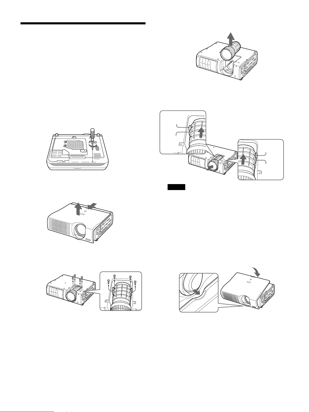
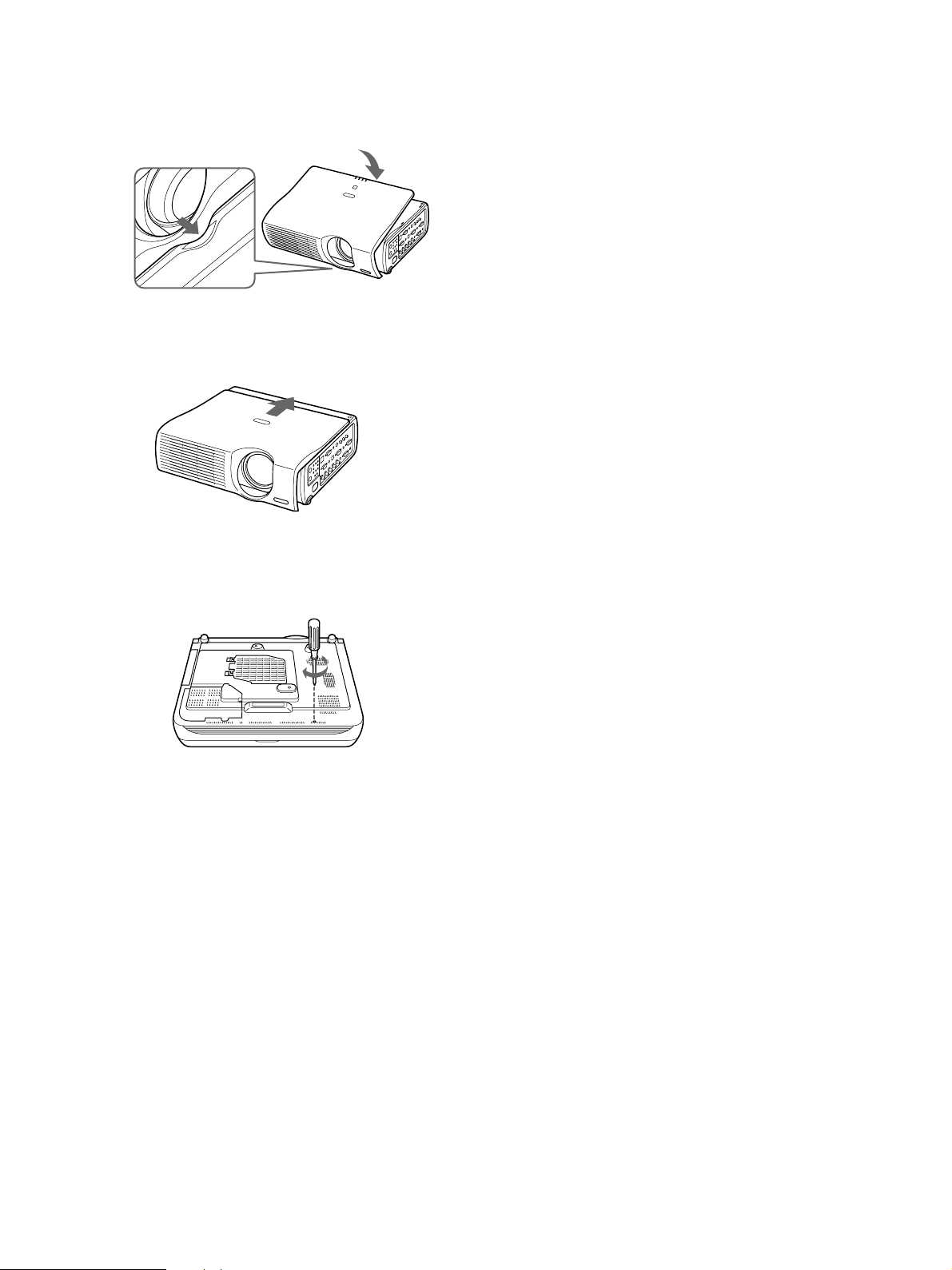
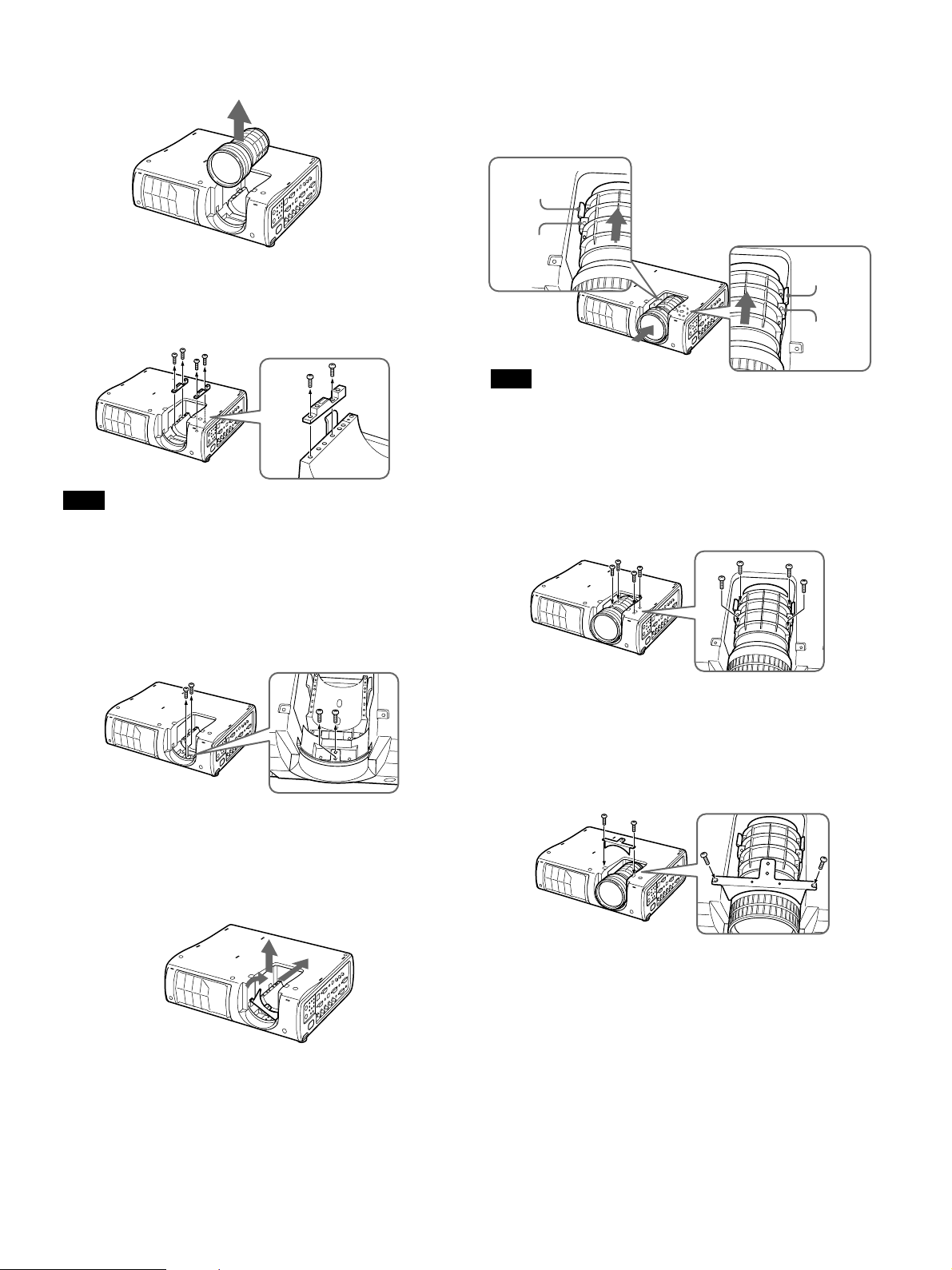
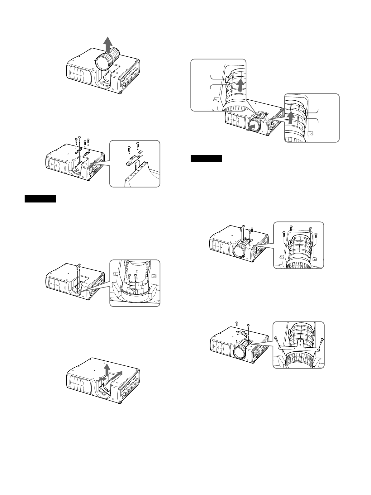
1 電源を切り、電源コードを抜く。
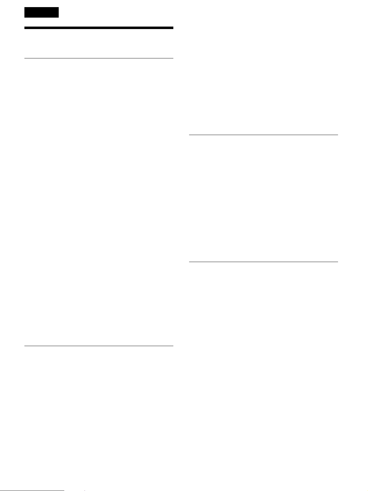
5 レンズを上に 持ち上げてはずす。
6 交換するレンズ側のストッパーをプロジェ クター 本体側のス
トッパーに押し当てる様にして位置を合わせ、レンズを組み
込む。
2 底面のネジをプラスドライバーではずす。
(長いネジ(M3)1本)
3 トップカバー (天面部レンズカバー)を前にスライドさせ なが
ら上方向にはずす。
4 レンズを固定している4本(M3×10、ワッシャー付 ) のネジを
はずす。
ストッパー
(本体側)
ストッパー
(レンズ側)
ご注意
レンズを組 み込む際、レンズに取り付けら れたストッパー(レン
ズ側)が上から見える向きにして取り付けてください。
ストッパー
(本体側)
ストッパー
(レンズ側)
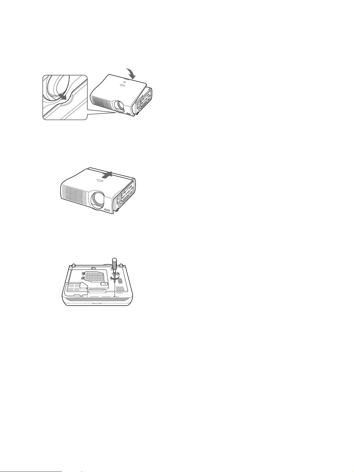
7 交換レンズを4本のネジ(M3×10、ワッシャー 付 )で締め付
け、しっかりと固定する。
8 トップカバーのレンズ 下突起部をベースの凹部に合わせて
から(左下図参照)トップカバー側のツメ(6ヶ所)をプロジ ェ
クター本体のスリットにはめ込む。
7
Page 8
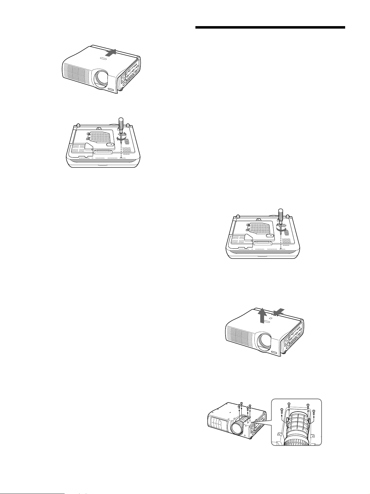
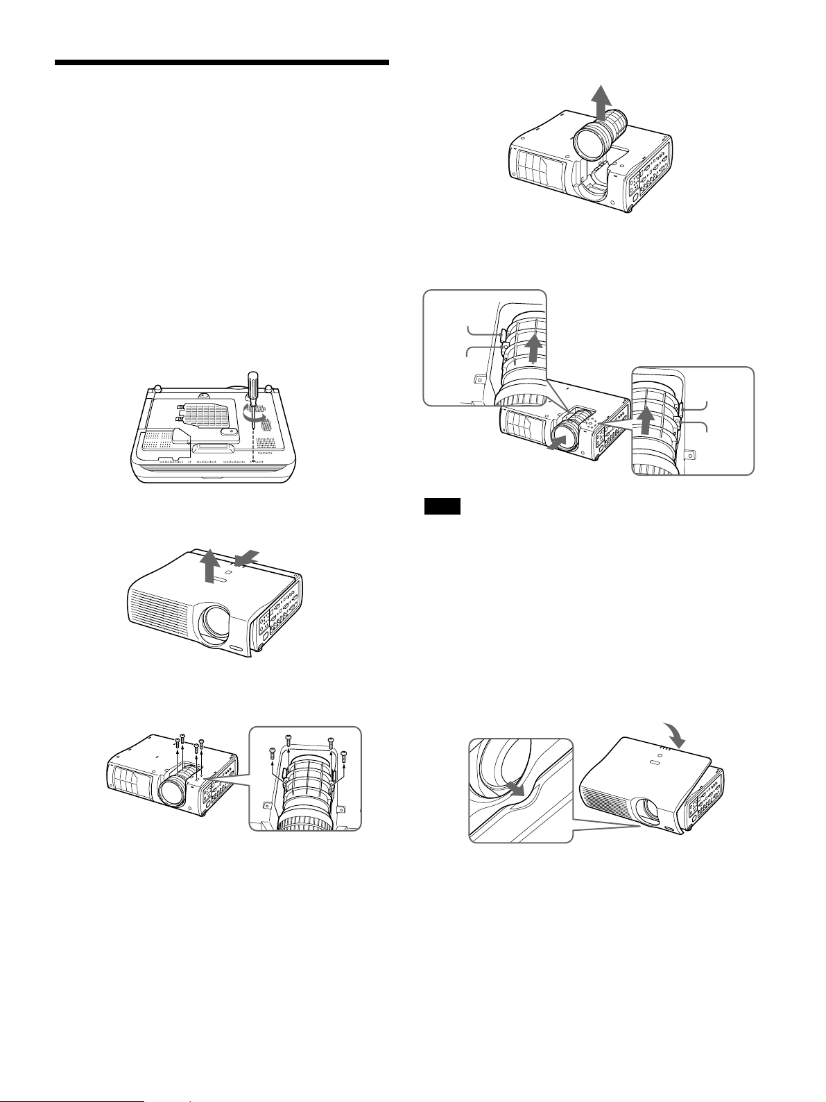
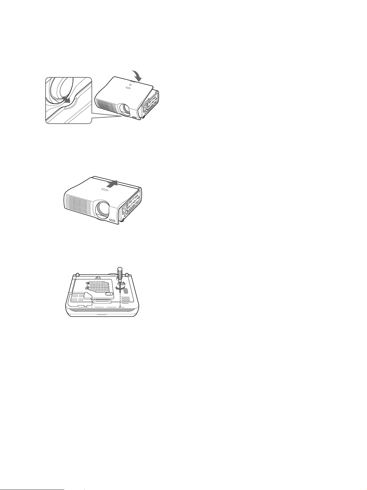
9 トップ カバーを後側へつき当るまでスライドさせる。
10底面にネジ(長いネジ(M3)1本) を締め付け る。
レンズ交換の際のご注意
• 取りはずしたレンズまたは取り 付けるレンズを置 くときは 、しっか
りした水平な台の上に静かに置いてください。レンズ面は傷つき
やすいので取り扱いには充分注意してください。
•レンズ 面には 手を触れないよう にしてく ださい。
リア投影(打ち込み角
0°
)
時のレンズ位置の変更の
しかた
リア 投 影 など の 場 合、打ち込み角を0°にす ることが できます。この
場合、レンズ位置を変更する必要があります。次の手順で、変更
してください。
打ち込み角を0°にする場合、 取り付けられるレンズは以下の通り
です。
• 標準レンズ
• 長焦点ズームレンズVPLL-ZM102
• 短焦点固定レンズVPLL-FM22
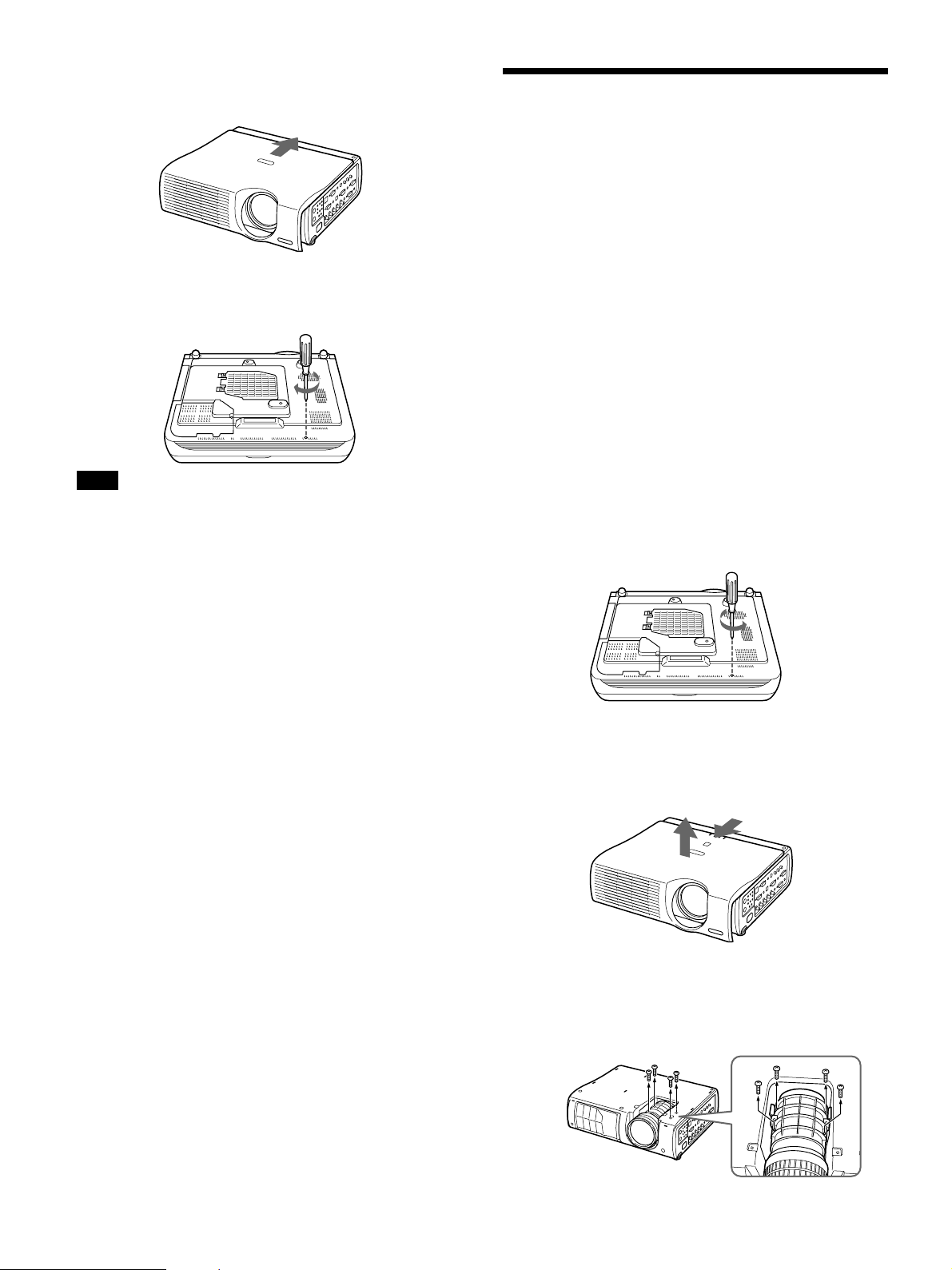
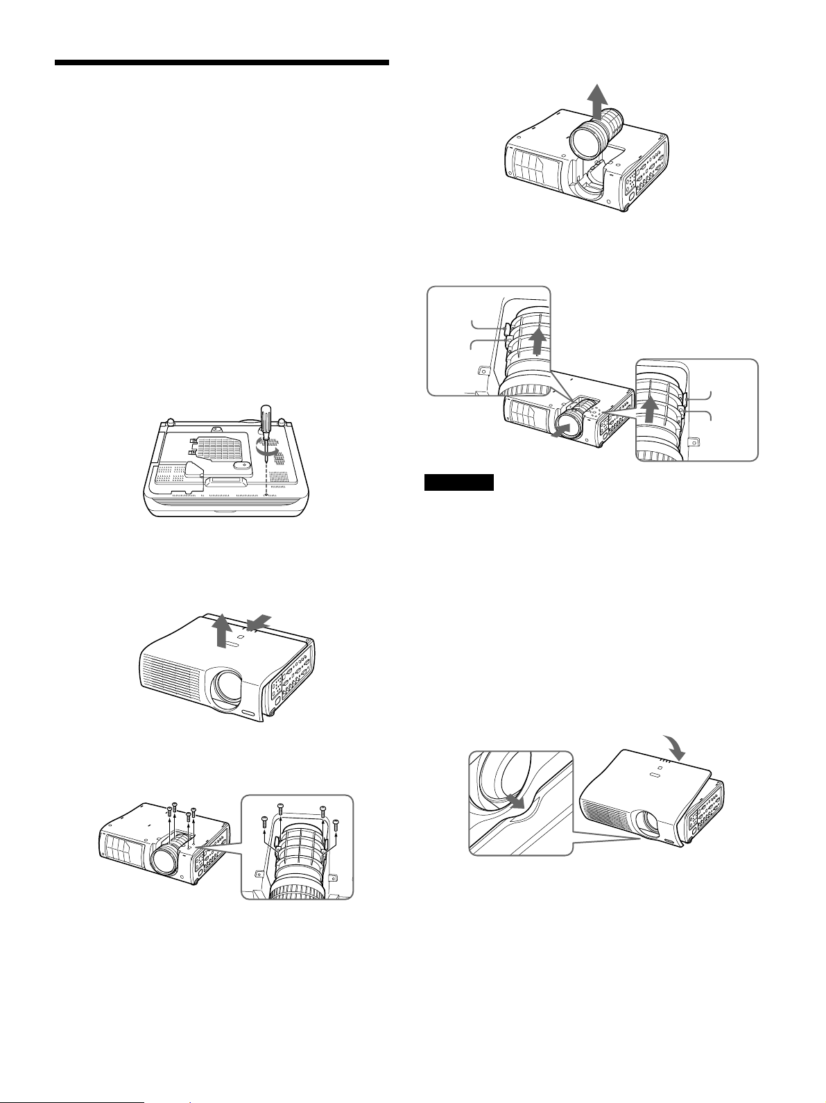
1 電源を切り、電源コードを抜く 。
2 底面のネジをプラスドライバーではずす。
(長いネジ(M3)1本)
3 トップ カバー (天面部レンズカバー)を前にスライドさせなが
ら上方向にはずす。
4 レンズを固定している4本(M3×10、ワッシャー付 )のネジ を
プラスドライバーではずす。
8
Page 9
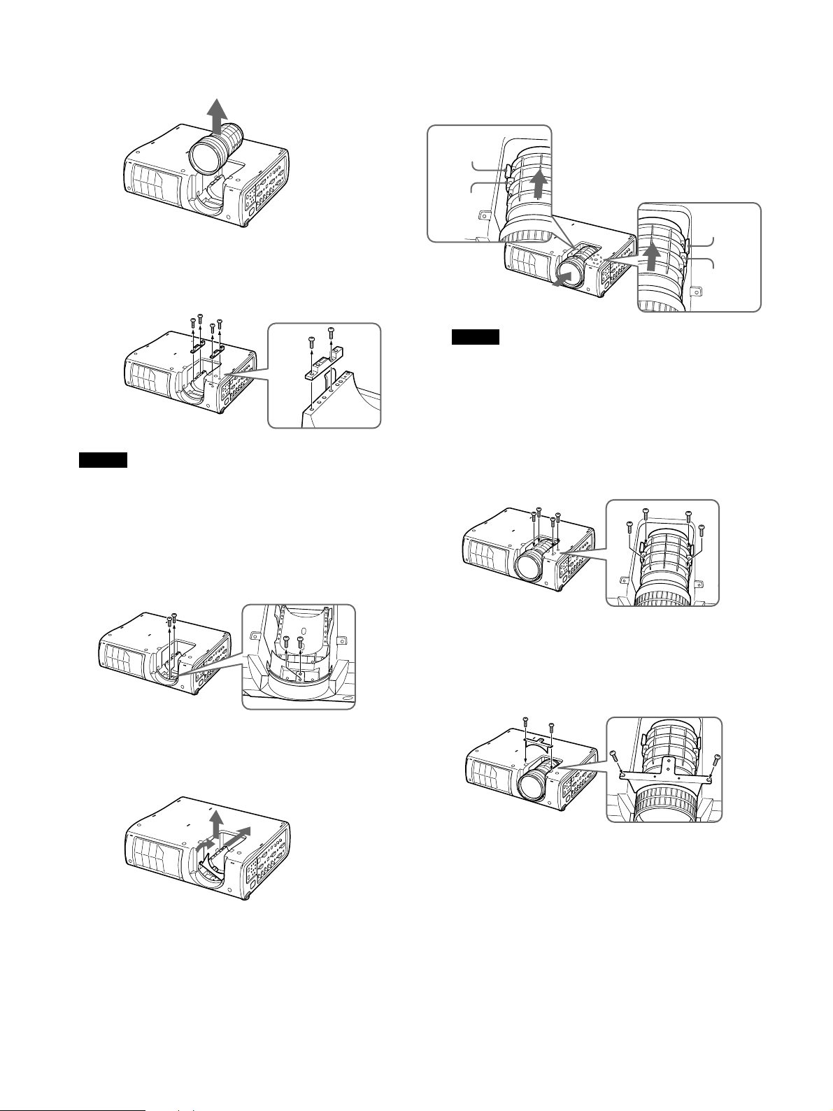
5 レンズを上に 持ち上げてはずす。
9 レンズ側のストッパーをプロジェクター本体側のストッパーに
押し当てるよう にして位置を合わせ、レンズを組み込む。
ストッパー
(本体側)
6 図示した左右のスペーサーの4本(M3×6、黒色)のネ ジ を
プラスドライバーではずし、取り除く 。
ご注意
ここで は ずしたスペーサーとネ ジ は後日必要と なる 場合があ り
ますので大切に保管しておいてください。
7 図の部分から2本のネジ(M3×8、 銀色)をはずし、 レンズ
ボトムカバーを 取りはずす。
ストッパー
(レンズ側)
ご注意
•レンズを組み込む際、レンズのス トッパーが上から見えるよう
にしてください。
ストッパー
(本体側)
ストッパー
(レンズ側)
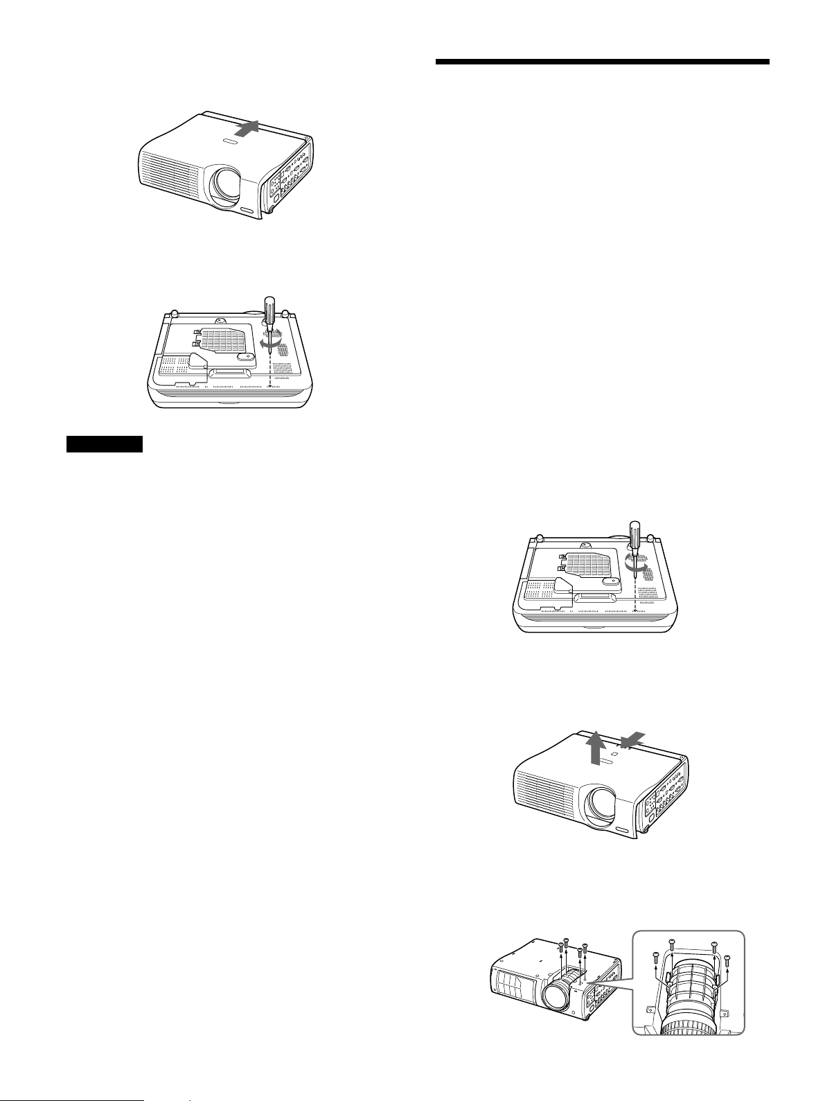
104本のネジ(M3×10、ワッシャー 付 )をプラ スドライバーで締
め付け、レンズをしっかり と固定する。
8 レンズボ トムカバーの左側を持ち上げて傾け、そのま ま右側
に寄せて、その状態のまま右上方向に取り外す。
11はずしたレンズボトムカバ ーを、レンズの上に図示向きに2
本のネジ(M3×8、銀色)で取りつける。
9
Page 10
12トップカバーのレンズ 下突起部をベースの凹部に合わせて
から(左下図参照)トップカバー側のツメ(6ヶ所)をプロジ ェ
クター本体のスリットにはめ込む。
13トップ カバーを 後側につき当るまで スライドさせる。
14底面にネジ(長いネジ(M3)1本) を締め付け る。
10
Page 11
English
Precautions
On safety
•Check that the operating voltage of your unit is
identical with the voltage of your local power
supply. If voltage adaptation is required, consult with
qualified Sony personnel.
•Should any liquid or solid object fall into the cabinet,
unplug the unit and have it checked by qualified
Sony personnel before operating it further.
•Unplug the unit from the wall outlet if it is not to be
used for several days.
•To disconnect the cord, pull it out by the plug. Never
pull the cord itself.
•The wall outlet should be near the unit and easily
accessible.
•The unit is not disconnected from the AC power
source (mains) as long as it is connected to the wall
outlet, even if the unit itself has been turned off.
•Do not look into the lens while the lamp is on.
•Do not place your hand or objects near the
ventilation holes — the air coming out is hot.
•Avoid using an extension cord with a low voltage
limited since it may cause the short-circuit and
physical incidents.
•To carry the projector, be sure to use the carrying
handle. Do not hold other parts of the projector,
especially the lens, nor catch your finger between the
handle, floor, and the projector.
•Do not catch your finger between the unit and
surface of the floor when moving the projector
installed on the floor.
•Be careful not to catch your finger in the cooling fan.
•Do not carry the projector with the cabinet on and
with its cover open.
•Install the projector on the floor or ceiling. Any other
installation causes a mulfunction such as color
irregularity or shortening lamp life.
•Do not install the unit in a location near heat sources
such as radiators or air ducts, or in a place subject to
direct sunlight, excessive dust or humidity,
mechanical vibration or shock.
•To avoid moisture condensation, do not install the
unit in a location where the temperature may rise
rapidly.
•Be sure to secure the cabinet cover firmly when
installing to the ceiling firmly.
On illumination
•To obtain the best picture, the front of the screen
should not be exposed to direct lighting or sunlight.
•Ceiling-mounted spot lighting is recommended. Use
a cover over fluorescent lamps to avoid lowering the
contrast ratio.
•Cover any windows that face the screen with opaque
draperies.
•It is desirable to install the projector in a room where
floor and walls are not of light-reflecting material. If
the floor and walls are of reflecting material, it is
recommended that the carpet and wall paper be
changed to a dark color.
On preventing internal heat build-up
•After you turn off the power with the I / 1 key on
the control panel or on the Remote Commander, do
not disconnect the unit from the wall outlet while the
cooling fan is still running.
•Do not disconnect the AC power cord from the wall
outlet while the fan is still running.
On installation
•When the projector is mounted on the ceiling, the
Sony PSS-610 Projector Suspension Support must be
used for installation.
•Allow adequate air circulation to prevent internal
heat build-up. Do not place the unit on surfaces
(rugs, blankets, etc.) or near materials (curtains,
draperies) that may block the ventilation holes.
Leave space of more than 30 cm (11
between the wall and the projector. Be aware that
room heat rises to the ceiling; check that the
temperature near the installation location is not
excessive.
7
/8 inches)
Caution
The projector is equipped with ventilation holes
(intake) at the bottom and ventilation holes (exhaust)
at the front. Do not block or place anything near these
holes, or internal heat build-up may occur, causing
picture degradation or damage to the projector.
11
Page 12

On cleaning
•To keep the cabinet looking new, periodically clean
it with a soft cloth. Stubborn stains may be removed
with a cloth lightly dampened with a mild detergent
solution. Never use strong solvents, such as thinner,
benzene, or abrasive cleansers, since these will
damage the cabinet.
•Avoid touching the lens. To remove dust on the lens,
use a soft dry cloth. Do not use a damp cloth,
detergent solution, or thinner.
•Clean the filter at regular intervals.
On repacking
•Save the original shipping carton and packing
material; they will come in handy if you ever have to
ship your unit. For maximum protection, repack your
unit as it was originally packed at the factory.
Overview
This manual describes how to install the Sony Data
Projector VPL-PX40/PX35, how to replace the lens,
how to change the lens position for rear projection
(optical axis angle: 0 degree), and installation
diagrams. When you replace the lens or change the
lens position, also refer to the Operating Instructions.
12
Page 13
Replacing the Lens
You can install the following two types of lenses in
the projector.
•VPLL-ZM102 Long Focus Zoom Lens
Follow the steps below to replace the lens.
For details on replacing the lens, also refer to the
installation manual supplied with the lens.
1 Turn off the power and disconnect the power
cable.
2 Remove the screw from the bottom of the unit by
using a Philips screwdriver.
(single long screw (M3))
5 Lift and remove the lens.
6 Align the positions so that the stopper for the new
lens is in contact with the stopper of the projector
unit, and then attach the lens.
Stopper
(Projector)
Stopper
(Lens)
Stopper
(Projector)
Stopper
(Lens)
3 Slide the top cover (top lens cover) forward, and
then lift it up to remove.
4 Remove the four screws (M3×10, with washers)
locking the lens.
Note
When attaching the lens, mount the stopper (lens side)
attached to the lens so that it is visible from the top.
7 Secure the replacement lens in place with four
screws (M3×10, with washers).
8 Line up the bump under the lens on the top cover
with the depression in the base (refer to the
diagram below), and then insert the six tabs on the
sides of the top cover into the slits on the
projector.
13
Page 14
9 Slide the top cover back until it makes contact
with the rear side.
10
Tighten the screw (single long screw (M3)) in
the bottom base.
Note
•The lens scratches easily, so when handling it,
always place it gently on a stable and level surface in
a horizonal position.
•Avoid touching the lens surface.
Changing the Lens
Position for Rear
Projection (Optical Axis
Angle: 0 degree)
For rear projection, you can set the optical axis angle
to 0 (zero). In this case, you will need to set the lens
position as follows.
You can install the following types of lenses for a zero
optical axis angle.
•Standard lens
•VPLL-ZM102 Long Focus Zoom Lens
•VPLL-FM22 Fixed Short Focus Lens
1 Turn off the power and disconnect the power
cable.
2 Remove the screw from the bottom of the unit by
using a Philips screwdriver .
(single long screw (M3))
3 Slide the top cover (top lens cover) forward, and
then lift it up to remove.
4 Remove the lens hood locking the lens by
loosening the four screws (M3×10, with washers)
with a Philips screwdriver.
14
Page 15
5 Lift and remove the lens.
6 Using a Philips screwdriver, remove the four
screws (M3×6, black) holding the left and right
spacers as shown in the diagram, and then remove
the spacers.
Note
The spacer and the screws may be needed later on.
Store them.
9 Align the positions so that the stopper for the lens
is in contact with the stopper of the projector unit,
and then attach the lens.
Stopper
(Projector)
Stopper
(Lens)
Note
For ease in identification when you install the lens,
make sure that the lens stopper is facing up.
10
Using a Philips screwdriver, tighten the four
screws (M3×10, with washers) that secure the
lens in place.
Stopper
(Projector)
Stopper
(Lens)
7 Remove the two screws (M3×8, silver) from the
section in the figure, and then remove the lens
bottom cover.
8 Lift up and tilt the left side of the lens bottom
cover, bring it toward the right side, and then
remove it in the right upward direction while
keeping it tilted.
11
Use the two screws (M3×8, silver) to mount the
removed lens bottom cover over the lens in the
orientation shown in the figure below.
15
Page 16
12
Line up the bump under the lens on the top cover
with the depression in the base (refer to the
diagram below), and then insert the six tabs on
the sides of the top cover into the slits on the
projector.
13
Slide the top cover back until it makes contact
with the rear side.
14
Tighten the screw (single long screw (M3)) in
the bottom base.
16
Page 17

Français
Précautions
Sécurité
•Vérifiez si la tension de service de votre appareil est
identique à la tension secteur locale. Si une
adaptation de la tension s’avère nécessaire, consultez
votre revendeur Sony ou un personnel qualifié.
•Si des liquides ou des solides pénètrent dans le
châssis, débranchez l’appareil et faites-le vérifier par
un personnel Sony qualifié avant de le remettre en
service.
•Débranchez l’appareil de la prise murale si vous
prévoyez de ne pas l’utiliser pendant plusieurs jours.
•Pour débrancher le cordon, saisissez-le par la fiche.
Ne tirez jamais sur le cordon proprement dit.
•La prise d’alimentation doit se trouver à proximité
du moniteur et être aisément accessible.
•Cet appareil n’est pas déconnecté de la source
d’alimentation (secteur) aussi longtemps qu’il reste
branché sur la prise murale, même si l’appareil
proprement dit a été mis hors tension.
•Ne regardez pas dans l’objectif lorsque la lampe est
allumée.
•Ne placez pas les mains ou des objets à proximité
des orifices de ventilation — l’air expulsé est chaud.
•Evitez d’utiliser une rallonge affichant une tension
basse limitée car cela pourrait provoquer un courtcircuit et des accidents physiques.
•Pour transporter le projecteur, veillez à utiliser la
poignée de transport. Ne saisissez pas d’autres
parties du projecteur – surtout pas l’objectif – et ne
vous coincez pas les doigts sous la poignée, le
plancher et le projecteur.
•Ne vous coincez pas les doigts entre l’appareil et le
sol lorsque vous déplacez le projecteur installé au
sol.
•Veillez à ne pas vous coincer les doigts dans le
ventilateur.
•Ne transportez pas le projecteur par le châssis
installé et avec le couvercle ouvert.
Installation
•Si vous installez le projecteur au plafond, vous devez
utiliser le support de suspension pour projecteur
Sony PSS-610.
•Assurez une circulation d’air adéquate afin d’éviter
toute surchauffe interne. Ne placez pas l’appareil sur
des surfaces textiles (tapis, couvertures, etc.) ni à
proximité de tissus (rideaux, draperies) qui risquent
d’obstruer les orifices de ventilation. Laissez un
espace d’au moins 30 cm (11
et le projecteur. N’oubliez pas que la chaleur dans
une pièce monte; vérifiez donc si la température au
niveau du lieu d’installation n’est pas excessive.
•Installez le projecteur au sol ou au plafond. Toute
autre installation provoquera un dysfonctionnement
(irrégularité des couleurs ou réduction de la durée de
vie de la lampe).
•N’installez pas l’appareil à proximité de sources de
chaleur telles que des radiateurs ou des conduits d’air
chaud et ne l’exposez pas au rayonnement direct du
soleil, à de la poussière ou à de l’humidité en excès,
ni à des vibrations mécaniques ou à des chocs.
•Pour éviter la condensation d’humidité, n’installez
pas l’appareil là où la température risque
d’augmenter rapidement.
•Veillez à fixer le couvercle du châssis
convenablement lorsque vous l’installez au plafond.
7
/8 pouces) entre le mur
Eclairage
•Pour obtenir la meilleure qualité d’image possible,
l’avant de l’écran ne doit pas être directement exposé
à la source d’éclairage ni au rayonnement solaire.
•Nous préconisons un éclairage au moyen de spots
fixés au plafond. Placez un écran sur les lampes
fluorescentes de façon à éviter une altération du
niveau de contraste.
•Occultez les fenêtres qui font face à l’écran au
moyen de draperies opaques.
•Il est préférable d’installer le projecteur dans une
pièce où le sol et les murs ne sont pas revêtus d’un
matériau réfléchissant la lumière. Si le sol et les murs
réfléchissent la lumière, nous vous conseillons de
remplacer le revêtement du sol et des murs par une
couleur sombre.
17
Page 18

Comment éviter l’accumulation de
chaleur à l’intérieur du projecteur
Aperçu
•Après avoir mis l’appareil hors tension à l’aide de la
touche I / 1 du panneau de commande ou de la
télécommande, ne déconnectez pas l’appareil de la
prise murale tant que le ventilateur de
refroidissement fonctionne.
•Ne débranchez pas le cordon d’alimentation de la
prise murale aussi longtemps que le ventilateur
tourne.
Attention
Le projecteur est équipé d’orifices de ventilation
(prise d’air) sur le dessous et d’orifices de ventilation
(sortie d’air) à l’avant. N’obstruez pas et ne placez
rien à proximité de ces orifices, faute de quoi vous
risquez de provoquer une surchauffe interne
susceptible d’entraîner une altération de l’image et
une détérioration du projecteur.
Entretien
•Pour conserver au châssis l’éclat du neuf, nettoyez-le
régulièrement à l’aide d’un chiffon doux. Les taches
tenaces s’éliminent en frottant avec un chiffon doux
légèrement imprégné d’une solution détergente
douce. N’utilisez en aucun cas des solvants puissants
tels que du diluant ou du benzène ni de nettoyants
abrasifs qui risqueraient d’altérer le fini du châssis.
•Ne touchez pas l’objectif. Pour éliminer la poussière
de l’objectif, utilisez un chiffon doux et sec.
N’utilisez pas de chiffon humide, de solution
détergente ni de diluant.
•Nettoyez l’objectif à intervalles réguliers.
Le présent mode d’emploi décrit comment installer les
projecteurs de données Sony VPL-PX40/PX35,
comment remplacer l’objectif, comment changer la
position de l’objectif pour la rétroprojection (angle
d’axe optique: 0 degré) et comporte également des
plans d’installation. Lors du remplacement de
l’objectif ou de la modification de la position de
l’objectif, reportez-vous également au mode d’emploi.
Remballage
•Conservez le carton d’emballage et les matériaux de
conditionnement, car ils constituent une protection
idéale en vue du transport de l’appareil. Pour une
protection maximale, remballez votre appareil
comme il a été emballé à l’origine en usine.
18
Page 19
Remplacement de
l’objectif
Vous pouvez installer les deux types d’objectifs
suivants sur le projecteur :
• Zoom à focale longue VPLL-ZM102
5 Retirez l’objectif en le soulevant.
Pour remplacer l’objectif, procédez comme suit.
Pour plus de détails sur le remplacement de l’objectif,
consultez également le manuel d’installation fourni avec
l’objectif.
1 Mettez le projecteur hors tension et débranchez
le cordon d’alimentation.
2 Retirez la vis du dessous du projecteur à l’aide
d’un tournevis cruciforme (longue vis unique
(M3)).
3 Faites coulisser le couvercle supérieur (couvercle
supérieur de l’objectif) en avant, puis retirez-le
en le soulevant.
6 Alignez les positions de façon que la butée du
nouvel objectif soit en contact avec la butée du
projecteur, puis montez l’objectif.
Butée
(Projecteur)
Butée
(Objectif)
Remarque
Lorsque vous installez l’objectif, tournez sa butée
(côté objectif) de façon qu’elle soit visible du haut.
Butée
(Projecteur)
Butée
(Objectif)
7 Fixez le nouvel objectif en place avec quatre vis
(M3×10, avec rondelles).
8 Alignez la bosse du couvercle supérieur située
sous l’objectif sur le creux du socle (voir le
schéma ci-dessous), puis insérez les six
languettes situées sur les côtés du couvercle
supérieur dans les fentes du projecteur.
4 Retirez les quatre vis (M3×10, avec rondelles) de
maintien de l’objectif.
19
Page 20
9 Faites coulisser le couvercle supérieur en arrière
jusqu’à ce qu’il touche le côté arrière.
10
Serrez la vis (longue vis unique (M3)) dans le
socle inférieur.
Remarques
•L’objectif se raye facilement. Manipulez-le avec
précautions et placez-le toujours délicatement à
l’horizontale sur une surface stable et plane.
• Évitez de toucher la surface de l’objectif.
Changement de la
position de l’objectif
pour la rétroprojection
(angle d’axe optique :
0 degré)
En rétroprojection, vous pouvez régler l’angle d’axe
optique sur 0 (zéro). Vous devez alors changer la
position de l’objectif de la façon suivante.
Pour un angle d’axe optique zéro, vous pouvez
installer les types d’objectifs suivants :
• Objectif standard
• Zoom à focale longue VPLL-ZM102
• Zoom à focale courte fixe VPLL-FM22
1 Mettez le projecteur hors tension et débranchez
le cordon d’alimentation.
2 Retirez la vis du dessous du projecteur à l’aide
d’un tournevis cruciforme
(longue vis unique (M3)).
3 Faites coulisser le couvercle supérieur (couvercle
supérieur de l’objectif) en avant, puis retirez-le
en le soulevant.
4 Retirez la protection de l’objectif maintenant
l’objectif en desserrant les quatre vis (M3×10,
avec rondelles) à l’aide d’un tournevis
cruciforme.
20
Page 21
5 Retirez l’objectif en le soulevant.
6 Ôtez les quatre vis (M3×6, noires) maintenant les
entretoises gauche et droite, comme indiqué sur
le schéma, à l’aide d’un tournevis cruciforme,
puis retirez les entretoises.
Remarque
Les entretoises et vis pourront resservir
ultérieurement. Conservez-les.
9 Alignez les positions de façon que la butée du
objectif soit en contact avec la butée du
projecteur, puis montez l’objectif.
Butée
(Projecteur)
Butée
(Objectif)
Remarque
Pour faciliter l’identification de l’objectif, installez
l’objectif avec sa butée vers le haut.
10
Serrez les quatre vis (M3×10, avec rondelles)
fixant l’objectif en place à l’aide d’un tournevis
cruciforme.
Butée
(Projecteur)
Butée
(Objectif)
7 Retirez les deux vis (M3×8, argent) de la partie
indiquée sur la figure, puis enlevez le couvercle
inférieur de l’objectif.
8 Soulevez et inclinez le bord gauche du couvercle
inférieur de l’objectif, poussez-le vers la droite,
puis tirez-le vers le haut et la droite en le
maintenant incliné.
11
Remettez le couvercle inférieur de l’objectif en
place dans le sens indiqué sur la figure cidessous à l’aide des deux vis (M3×8, argent).
21
Page 22
12
Alignez la bosse du couvercle supérieur située
sous l’objectif sur le creux du socle (voir le
schéma ci-dessous), puis insérez les six
languettes situées sur les côtés du couvercle
supérieur dans les fentes du projecteur.
13
Faites coulisser le couvercle supérieur en arrière
jusqu’à ce qu’il touche le côté arrière.
14
Serrez la vis (longue vis unique (M3)) dans le
socle inférieur.
22
Page 23

Español
Precauciones
Seguridad
•Asegúrese de que la tensión de funcionamiento de la
unidad coincide con la del suministro eléctrico local.
Si es necesario adaptar la tensión, consulte con
personal Sony especializado.
•Si se introduce algún objeto sólido o líquido en la
unidad, desenchúfela y haga que sea examinada por
personal Sony especializado antes de volver a
utilizarla.
•Desenchufe la unidad de la toma de red si no va a
utilizarla durante varios días.
•Para desconectar el cable, tire del enchufe, nunca del
propio cable.
•La toma de red debe estar situada cerca de la unidad
y ser de fácil acceso.
•La unidad no estará desconectada de la fuente de
alimentación de CA (toma de corriente) mientras
esté conectada a la toma de red, aunque la haya
apagado.
•No mire al objetivo mientras la lámpara esté
encendida.
•No acerque la mano ni objetos a los orificios de
ventilación, ya que el aire que sale es caliente.
•Evite el uso de cables prolongadores de baja tensión
limitada, ya que pueden producirse cortocircuitos y
daños físicos.
•Para transportar el proyector, asegúrese de utilizar el
asa de transporte. No agarre otras partes de la
unidad, especialmente el objetivo, y tenga cuidado
de no pillarse los dedos entre el asa, el suelo y el
proyector.
•Tenga cuidado de no pillarse los dedos entre la
unidad y el suelo cuando mueva el proyector
instalado en el suelo.
•Tenga cuidado de no pillarse los dedos con el
ventilador de enfriamiento.
•No transporte el proyector con la cubierta puesta ni
abierta.
Instalación
•Si instala el proyector en el techo, debe emplearse el
soporte de suspensión para proyector PSS-610 de
Sony.
•Con el fin de evitar el recalentamiento interno de la
unidad, permita que ésta reciba una ventilación
adecuada. No sitúe la unidad sobre superficies
(mantas, alfombras, etc.) ni cerca de materiales
(cortinas, tapices) que puedan bloquear los orificios
de ventilación. Deje un espacio superior a 30 cm (11
7
/8 pulgadas) entre la pared y el proyector. Tenga en
cuenta que el calor del ambiente se eleva hacia el
techo (compruebe que la temperatura en el lugar de
instalación no sea excesiva).
•Instale el proyector en el suelo o en el techo.
Cualquier otro tipo de instalación provocará fallos de
funcionamiento, como irregularidades del color o la
reducción de la vida útil de la lámpara.
•No instale la unidad en lugares próximos a fuentes
térmicas, como radiadores o conductos de aire
caliente, ni en lugares expuestos a la luz solar
directa, polvo excesivo o humedad, ni vibraciones o
golpes mecánicos.
•Para evitar la condensación de humedad, no instale
la unidad en lugares donde la temperatura pueda
aumentar rápidamente.
•Asegúrese de fijar firmemente la cubierta al realizar
la instalación en el techo.
Iluminación
•Para obtener la mejor calidad de imagen posible, no
exponga la parte frontal de la pantalla a iluminación
o luz solar directas.
•Se recomienda instalar una lámpara proyectora en el
techo. Cubra las lámparas fluorescentes para evitar la
disminución de la relación de contraste.
•Cubra con telas opacas las ventanas que estén
orientadas hacia la pantalla.
•Es preferible instalar el proyector en una sala cuyo
suelo y paredes no se compongan de materiales que
reflejen la luz. Si el suelo y las paredes se componen
de dicho tipo de materiales, se recomienda cambiar
el color de la alfombra y del papel pintado de la
pared por otro oscuro.
23
Page 24

Prevención del recalentamiento interno
•Tras desactivar la alimentación con la tecla I / 1 del
panel de control o del mando a distancia, no
desconecte la unidad de la toma de red hasta que se
detenga el ventilador de enfriamiento.
•No desconecte el cable de alimentación de CA de la
toma de red mientras sigue funcionando el
ventilador.
Precaución
El proyector va equipado con orificios de ventilación
de aspiración en la parte inferior y de exhaustación en
la parte frontal. No bloquee estos orificios ni coloque
nada cerca de los mismos, ya que puede producirse
recalentamiento interno, causando deterioro de la
imagen o daños al proyector.
Limpieza
•Para mantener el exterior de la unidad nuevo,
límpielo periódicamente con un paño suave. Para
eliminar las manchas persistentes, utilice un paño
ligeramente humedecido con una solución detergente
poco concentrada. No emplee nunca disolventes
concentrados, como diluyentes, bencina o productos
de limpieza abrasivos, ya que pueden dañar el
acabado.
•Evite tocar el objetivo. Para eliminar el polvo de
éste, emplee un paño seco y suave. No utilice un
paño húmedo, soluciones detergentes ni diluyentes.
•Limpie el filtro con regularidad.
Introducción
En este manual se describen los procedimientos para
instalar el proyector de datos de Sony, modelos VPLPX40/PX35, sustituir el objetivo y cambiar la posición
del objetivo para la proyección posterior (ángulo de
eje óptico de 0 grados) y se ofrecen diagramas de
instalación. Al sustituir el objetivo o cambiar su
posición, consulte las instrucciones de uso.
Embalaje
•Conserve la caja original de embalaje, ya que le
resultará útil cuando vaya a transportar la unidad.
Para obtener la máxima protección posible, embale
la unidad como la recibió de fábrica.
24
Page 25

Sustitución del objetivo
Es posible instalar estos dos tipos de objetivo en el
proyector.
• Objetivo zoom de enfoque largo VPLL-ZM102
Siga estos pasos para sustituir el objetivo.
Para obtener información más detallada sobre cómo
sustituir el objetivo, también puede consultar el manual de
instalación suministrado con el objetivo.
1 Apague la unidad y desconecte el cable de
alimentación.
5 Levante y quite el objetivo.
6 Alinee las posiciones de forma que se toquen los
topes del nuevo objetivo y de la unidad del
proyector, y a continuación coloque el objetivo.
2 Extraiga el tornillo de la parte inferior de la unidad
con un destornillador Philips. (un único tornillo
largo (M3))
3 Deslice la cubierta superior (cubierta superior del
objetivo) hacia delante, y después levántela para
quitarla.
4 Extraiga los cuatro tornillos (M3×10, con
arandelas) que fijan el objetivo.
Tope
(Proyector)
Tope
(Objetivo)
Nota
Al colocar el objetivo, monte el tope (lado del
objetivo) colocado en el objetivo de forma que sea
visible desde arriba.
Tope
(Proyector)
Tope
(Objetivo)
7 Sujete la lente de reemplazo en su sitio con cuatro
tornillos (M3×10, con arandelas).
8 Alinee la protuberancia de debajo de la lente de la
cubierta superior con la depresión de la base
(consulte el diagrama de abajo), y después inserte
las seis lengüetas de los lados de la cubierta
superior en las hendiduras del proyector.
25
Page 26

9 Vuelva a poner la cubierta superior
deslizándola hasta que toque contra el lado
posterior.
Cambio de la posición
del objetivo para la
proyección posterior
(ángulo de eje óptico: 0
grados)
10Apriete el tornillo (un único tornillo
largo(M3)) de la parte inferior de la unidad.
Notas
• El objetivo se raya fácilmente. Por tanto, al
manipularlo es conveniente colocarlo suavemente
sobre una superficie estable y nivelada en posición
horizontal.
•Procure no tocar la superficie del objetivo.
Para la proyección posterior, puede ajustar el ángulo
de eje óptico en 0 (cero). En este caso, es necesario
ajustar la posición del objetivo tal como se describe a
continuación.
Es posible instalar los siguientes tipos de objetivo para
un ángulo de eje óptico de cero:
•Objetivo estándar
•Objetivo zoom de enfoque largo VPLL-ZM102
•Objetivo zoom de enfoque corto VPLL-FM22
1 Apague la unidad y desconecte el cable de
alimentación.
2 Extraiga el tornillo de la parte inferior de la unidad
con un destornillador Philips.
(un único tornillo largo (M3))
26
3 Deslice la cubierta superior (cubierta superior del
objetivo) hacia delante, y después levántela para
quitarla.
4 Quite la cubierta que sujeta el objetivo. Para ello,
afloje los cuatro tornillos (M3×10, con arandelas)
con un destornillados Philips.
Page 27

5 Levante y extraiga el objetivo.
6 Utilizando un destornillador Philips, quite los
cuatro tornillos (M3×6, negros) sujetando los
espaciadores izquierdo y derecho como se muestra
en el diagrama, y después quite los espaciadores.
Nota
Es posible que necesite el espaciados y los tornillos
más adelante. Consérvelos.
9 Alinee las posiciones de forma que se toquen los
topes del objetivo y de la unidad del proyector, y a
continuación coloque el objetivo.
Tope
(Proyector)
Tope
(Objetivo)
Nota
Para facilitar la identificación del objetivo al
instalarlo, asegúrese de que el tope del objetivo se
encuentra en la parte superior.
Tope
(Proyector)
Tope
(Objetivo)
10Utilizando un destornillador Philips, apriete
los cuatro tornillos (M3×10, con arandelas)
que sujetan la lente en su sitio.
7 Extraiga los dos tornillos (M3×8, plateados) de la
sección indicada en la figura, y a continuación
quite la cubierta inferior del objetivo.
8 Levante e incline el lado izquierdo de la cubierta
inferior del objetivo, muévala hacia el lado
derecho, y a continuación retírela en dirección
hacia la derecha y arriba mientras la mantiene
inclinada.
11Utilice los dos tornillos (M3×8, plateados)
para montar la cubierta inferior del objetivo
quitada sobre el objetivo en la orientación
mostrada en la figura de abajo.
27
Page 28

12Alinee la protuberancia de debajo de la lente
de la cubierta superior con la depresión de la
base (consulte el diagrama de abajo), y
después inserte las seis lengüetas de los
lados de la cubierta superior en las
hendiduras del proyector.
13Vuelva a poner la cubierta superior
deslizándola hasta que toque contra el lado
posterior.
14Apriete el tornillo (un único tornillo
largo(M3)) de la parte inferior de la unidad.
28
Page 29

Deutsch
Sicherheitsmaßnahmen
Sicherheit
•Achten Sie darauf, daß die Betriebsspannung des
Geräts der lokalen Stromversorgung entspricht.
Wenn die Betriebsspannung angepaßt werden muß,
wenden Sie sich bitte an qualifiziertes Fachpersonal
von Sony.
•Sollten Fremdkörper oder Flüssigkeiten in das Gerät
gelangen, trennen Sie es von der Netzsteckdose.
Lassen Sie das Gerät von qualifiziertem
Fachpersonal von Sony überprüfen, bevor Sie es
wieder benutzen.
•Wollen Sie das Gerät einige Tage nicht benutzen,
ziehen Sie den Netzstecker aus der Steckdose.
•Ziehen Sie zum Lösen des Netzsteckers immer am
Stecker, niemals am Kabel.
•Die Netzsteckdose sollte sich in der Nähe des Geräts
befinden und leicht zugänglich sein.
•Das Gerät bleibt auch in ausgeschaltetem Zustand
mit dem Stromnetz verbunden, solange das
Netzkabel mit der Netzsteckdose verbunden ist.
•Schauen Sie nicht in das Objektiv, während die
Birne eingeschaltet ist.
•Stellen Sie keine Gegenstände in die Nähe der
Lüftungsöffnungen, und halten Sie auch Ihre Hände
davon fern — die ausströmende Luft ist heiß!
•Verwenden Sie kein Verlängerungskabel, das nur für
geringe Spannungen ausgelegt ist. Ein solches Kabel
könnte zu Kurzschlüssen und sonstigen Unfällen
führen.
•Tragen Sie den Projektor immer am Tragegriff.
Halten Sie den Projektor, wenn Sie ihn tragen, nicht
an anderen Stellen, vor allem nicht am Objektiv.
Achten Sie auch darauf, die Hände nicht zwischen
Tragegriff, Fußboden und Projektor einzuklemmen.
•Wenn Sie einen am Boden installierten Projektor
bewegen, achten Sie darauf, die Hände nicht
zwischen Fußboden und Projektor einzuklemmen.
•Greifen Sie auf keinen Fall in den Ventilator.
•Tragen Sie einen in einen Ständer eingebauten
Projektor nicht mit geöffneter Abdeckung.
Aufstellung
•Mit Hilfe der Projektoraufhängung PSS-610 von
Sony können Sie den Projektor an der Decke
installieren.
•Achten Sie auf ausreichende Luftzufuhr, damit sich
im Gerät kein Wärmestau bildet. Stellen Sie das
Gerät nicht auf Oberflächen wie Teppichen oder
Decken oder in der Nähe von Materialien wie
Gardinen und Wandbehängen auf, die die
Lüftungsöffnungen blockieren könnten. Achten Sie
auf einen Mindestabstand von 30 cm zwischen der
Wand und dem Projektor. Denken Sie bei
Deckeninstallationen daran, daß Wärme zur Decke
aufsteigt. Achten Sie darauf, daß die Temperatur am
Installationsort nicht zu hoch ist.
•Installieren Sie den Projektor am Boden oder an der
Decke. Bei Installation in einer anderen Position
kann es zu Fehlfunktionen wie Farbstörungen
kommen, und die Lebensdauer der Birne ist
möglicherweise verkürzt.
•Stellen Sie das Gerät nicht in der Nähe von
Wärmequellen wie Heizkörpern oder
Warmluftauslässen oder an Orten auf, an denen es
direktem Sonnenlicht, außergewöhnlich viel Staub
oder Feuchtigkeit, mechanischen Vibrationen oder
Stößen ausgesetzt ist.
•Installieren Sie das Gerät nicht an einem Ort, an dem
die Temperatur sehr schnell ansteigen und zu
Feuchtigkeitskondensation führen könnte.
•Achten Sie darauf, die Abdeckung sicher zu
befestigen, wenn Sie das Gerät an der Decke
installieren.
Beleuchtung
•Um eine optimale Bildqualität zu erzielen, achten Sie
darauf, daß kein Licht direkt auf die Vorderseite des
Projektionsschirms fällt.
•Empfohlen wird eine Spotbeleuchtung an der Decke.
Leuchtstoffröhren sollten Sie abdecken, um eine
Verminderung des Kontrasts zu verhindern.
•Verhängen Sie Fenster, die dem Projektionsschirm
direkt gegenüber liegen.
•Sie sollten den Projektor in einem Raum installieren,
in dem Boden und Wände mit einem Material
verkleidet sind, das kein Licht reflektiert. Ist dies
nicht möglich, sollten Sie für Bodenbelag und
Wandverkleidung ein dunkles Material wählen.
29
Page 30

Vermeiden eines internen Hitzestaus
•Nachdem Sie das Gerät mit der Taste I / 1 auf dem
Bedienfeld oder mit der Fernbedienung ausgeschaltet
haben, trennen Sie es nicht von der Netzsteckdose,
solange der Ventilator noch läuft.
•Lösen Sie nicht das Netzkabel von der
Netzsteckdose, solange der Ventilator noch läuft.
Achtung
Der Projektor ist an der Unterseite mit
Ansaugöffnungen und an der Vorderseite mit
Auslaßöffnungen ausgestattet. Blockieren Sie diese
Öffnungen nicht, und stellen Sie keine Gegenstände in
die Nähe der Öffnungen. Andernfalls kann es zu
einem Wärmestau kommen, der zu einer Verringerung
der Bildqualität oder Schäden am Projektor führen
kann.
Reinigung
•Damit das Gehäuse immer wie neu aussieht, reinigen
Sie es regelmäßig mit einem weichen Tuch.
Hartnäckige Verschmutzungen können Sie mit
einem Tuch entfernen, das Sie leicht mit einem
milden Reinigungsmittel angefeuchtet haben.
Verwenden Sie keine starken Lösungsmittel wie
Verdünner oder Benzin und keine Scheuermittel, da
diese die Gehäuseoberfläche angreifen.
•Berühren Sie das Objektiv nicht. Mit einem weichen,
trockenen Tuch können Sie Staub vom Objektiv
entfernen. Feuchten Sie das Tuch nicht an, und
benutzen Sie weder eine Reinigungsflüssigkeit noch
Verdünner.
•Reinigen Sie den Filter in regelmäßigen Abständen.
Übersicht
In dieser Anleitung wird beschrieben, wie Sie den
Datenprojektor VPL-PX40/PX35 von Sony
installieren, das Objektiv austauschen und die
Objektivposition für die Rückprojektion (Winkel der
optischen Achse: 0 Grad) ändern. Außerdem sind
Installationsdiagramme abgebildet. Schlagen Sie bitte
auch in der Bedienungsanleitung nach, wenn Sie das
Objektiv austauschen oder die Objektivposition
ändern wollen.
Verpacken
•Bewahren Sie Originalkarton und
Verpackungsmaterialien gut auf für den Fall, daß Sie
das Gerät später einmal transportieren müssen. Am
besten geschützt ist das Gerät beim Transport, wenn
Sie es wieder so verpacken, wie es geliefert wurde.
30
Page 31

Austauschen des
Objektivs
Die folgenden beiden Objektivtypen können im
Projektor installiert werden.
•Zoom-Objektiv VPLL-ZM102 mit langer
Brennweite
5 Heben Sie das Objektiv nach oben heraus.
Tauschen Sie das Objektiv nach dem folgenden
Verfahren aus.
Einzelheiten zum Austauschen des Objektivs finden Sie
auch in der mit dem Objektiv gelieferten
Installationsanleitung.
1 Schalten Sie den Projektor aus, und ziehen Sie
das Netzkabel ab.
2 Entfernen Sie die Schraube (einzelne lange
Schraube (M3)) von der Unterseite des Gerätes
mit einem Kreuzschlitzschraubenzieher.
3 Schieben Sie die Abdeckhaube (obere
Objektivabdeckung) nach vorn, und heben Sie
sie nach oben ab.
6 Richten Sie die Positionen so aus, dass der
Stopper des neuen Objektivs den Stopper der
Projektoreinheit berührt, und setzen Sie dann das
Objektiv ein.
Stopper
(Projektor)
Stopper
(Objektiv)
Hinweis
Richten Sie den am Objektiv angebrachten Stopper
(Objektivseite) beim Einsetzen des Objektivs so aus,
dass er von oben sichtbar ist.
Stopper
(Projektor)
Stopper
(Objektiv)
7 Befestigen Sie das Austausch-Objektiv mit vier
Schrauben (M3×10, mit Unterlegscheiben).
4 Entfernen Sie die vier Befestigungsschrauben
(M3×10, mit Unterlegscheiben) des Objektivs.
8 Richten Sie den Vorsprung unter dem Objektiv
an der Abdeckhaube auf die Vertiefung in der
Basis aus (siehe nachstehende Abbildung), und
führen Sie dann die sechs Zungen an den Seiten
der Abdeckhaube in die Schlitze des Projektors
ein.
31
Page 32

9 Schieben Sie die Abdeckhaube zurück, bis sie
die Rückseite berührt.
10
Ziehen Sie die Schraube (einzelne lange
Schraube (M3)) auf der Unterseite an.
Hinweise
•Legen Sie das empfindliche Objektiv bei der
Handhabung immer sachte und waagerecht auf eine
stabile und ebene Unterlage, um es vor Kratzern zu
schützen.
•Vermeiden Sie eine Berührung der
Linsenoberfläche.
Ändern der
Objektivposition für
Rückprojektion (Winkel
der optischen Achse:
0 Grad)
Für die Rückprojektion können Sie den Winkel der
optischen Achse auf 0 (Null) einstellen. In diesem Fall
müssen Sie die Objektivposition wie folgt ändern.
Wenn Sie den Winkel der optischen Achse auf Null
einstellen wollen, können Sie die folgenden
Objektivtypen installieren.
•Standardobjektiv
•Zoom-Objektiv VPLL-ZM102 mit langer
Brennweite
•Objektiv VPLL-FM22 mit feststehender kurzer
Brennweite
1 Schalten Sie den Projektor aus, und ziehen Sie
das Netzkabel ab.
2 Entfernen Sie die Schraube (einzelne lange
Schraube (M3)) von der Unterseite des Gerätes
mit einem Kreuzschlitzschraubenzieher.
32
3 Schieben Sie die Abdeckhaube (obere
Objektivabdeckung) nach vorn, und heben Sie
sie nach oben ab.
4 Entfernen Sie die Objektivabdeckung, mit der
das Objektiv gesichert ist, indem Sie die vier
Schrauben (M3×10, mit Unterlegscheiben) mit
einem Kreuzschlitzschraubenzieher lösen.
Page 33

5 Heben Sie das Objektiv nach oben heraus.
6 Entfernen Sie mit einem
Kreuzschlitzschraubenzieher die vier Schrauben
(M3×6, schwarz), während Sie die
Abstandsstücke auf der linken und rechten Seite
halten, wie in der Abbildung gezeigt, und
nehmen Sie dann die Abstandsstücke ab.
Hinweis
Die Abstandsstücke und die Schrauben werden
möglicherweise später wieder benötigt. Bewahren Sie
die Teile daher auf.
9 Richten Sie die Positionen so aus, dass der
Stopper des Objektivs den Stopper der
Projektoreinheit berührt, und setzen Sie dann das
Objektiv ein.
Stopper
(Projektor)
Stopper
(Objektiv)
Hinweis
Um die Identifizierung bei der Installation des
Objektivs zu erleichtern, stellen Sie sicher, dass der
Objektivstopper nach oben weist.
10
Ziehen Sie mit einem
Kreuzschlitzschraubenzieher die vier Schrauben
(M3×10, mit Unterlegscheiben) an, mit denen
das Objektiv befestigt ist.
Stopper
(Projektor)
Stopper
(Objektiv)
7 Entfernen Sie die zwei Schrauben (M3×8,
silbern) von der in der Abbildung gezeigten
Stelle, und nehmen Sie dann die untere
Objektivabdeckung ab.
8 Heben Sie die linke Seite der unteren
Objektivabdeckung schräg an, drücken Sie sie
nach rechts, und entfernen Sie die Abdeckung
dann nach rechts oben, während Sie sie schräg
halten.
11
Benutzen Sie die zwei Schrauben (M3×8,
silbern), um die entfernte untere
Objektivabdeckung so auf das Objektiv zu
montieren, wie in der nachstehenden Abbildung
gezeigt.
33
Page 34

12
Richten Sie den Vorsprung unter dem Objektiv
an der Abdeckhaube auf die Vertiefung in der
Basis aus (siehe nachstehende Abbildung), und
führen Sie dann die sechs Zungen an den Seiten
der Abdeckhaube in die Schlitze des Projektors
ein.
13
Schieben Sie die Abdeckhaube zurück, bis sie
die Rückseite berührt.
14
Ziehen Sie die Schraube (einzelne lange
Schraube (M3)) auf der Unterseite an.
34
Page 35

Italiano
Precauzioni
Sicurezza
•Verificare che la tensione operativa dell’apparecchio
corrisponda a quella dell’alimentazione locale. Se
fosse necessario un adattatore di tensione, contattare
il personale qualificato Sony.
•Se dovessero penetrare corpi liquidi o solidi
all’interno dell’apparecchio, scollegarlo e farlo
controllare da personale qualificato Sony prima di
riutilizzarlo.
•Scollegare l’apparecchio dalla presa di rete se non si
intende utilizzarlo per diversi giorni.
•Per scollegare il cavo, tirare afferrando la spina e mai
il cavo stesso.
•La presa di rete deve trovarsi vicino all’apparecchio
ed essere facilmente accessibile.
•L’apparecchio non è scollegato dalla sorgente di
alimentazione CA (di rete) fino a che resta collegato
alla presa a muro, anche se l’interruttore è stato
spento.
•Non guardare dentro l’obiettivo quando la lampada è
accesa.
•Non avvicinare la mano o alcun oggetto alle prese di
ventilazione — l’aria che ne fuoriesce ha una
temperatura elevata.
•Evitare l’uso di una prolunga con un basso voltaggio
in quanto potrebbe provocare cortocircuiti e danni
fisici.
•Per trasportare il proiettore assicurarsi di utilizzare la
maniglia di trasporto. Non afferrare altre parti del
proiettore, specialmente l’obiettivo. Fare attenzione a
non incastrare le dita tra la maniglia, il pavimento e
il proiettore.
•Non infilare le dita tra l’apparecchio e la superficie
del pavimento quando si sposta il proiettore
installato sul pavimento.
•Fare attenzione a non infilare le dita nella ventola di
raffreddamento.
•Non trasportare il proiettore con sopra gli accessori e
il coperchio aperto.
Installazione
•Se il proiettore viene installato al soffitto, è
necessario utilizzare il supporto di sospensione Sony
PSS-610.
•Consentire una buona circolazione d’aria all’interno
dell’apparecchio per evitarne il surriscaldamento.
Non collocare l’apparecchio su superfici come
tappeti, coperte, ecc., o vicino a materiali come tende
e drappeggi che potrebbero bloccare le prese di
ventilazione. Lasciare uno spazio di almeno 30 cm
fra la parete e il proiettore. Dal momento che il
calore si propaga verso l’alto, verificare che la
temperatura circostante il luogo d’installazione non
sia troppo elevata.
•Installare il proiettore al pavimento o al soffitto.
Ogni altro tipo di installazione può causare problemi
di funzionamento come ad esempio un’irregolarità
del colore o una durata della lampada più breve.
•Non installare l’apparecchio nei pressi di fonti di
calore come radiatori o condotti d’aria calda, né in
luoghi esposti alla luce diretta del sole, polvere
eccessiva, umidità, vibrazioni o urti meccanici.
•Per evitare la formazione di condensa, non installare
l’apparecchio in un ambiente soggetto ad aumenti di
temperatura repentini.
•Assicurarsi che il coperchio del rivestimento sia ben
saldo quando viene effettuata l’installazione al
soffitto.
Illuminazione
•Per ottenere un’immagine ottimale, la parte anteriore
dello schermo non deve essere esposta a
illuminazione diretta o alla luce diretta del sole.
•Si consiglia un’illuminazione costituita da faretti
installati al soffitto. Per evitare di abbassare il
rapporto del contrasto, schermare le lampade
fluorescenti vicine al proiettore.
•Coprire con tende opache eventuali finestre poste di
fronte allo schermo.
•Si consiglia di installare l’apparecchio in una stanza
dove pavimento e pareti non siano in materiale che
riflette la luce. Diversamente, si consiglia di
applicare materiali di rivestimento di colore scuro
per prevenire il surriscaldamento interno.
35
Page 36

Prevenzione del surriscaldamento interno
•Dopo aver disattivato l’alimentazione con il tasto
I / 1 sul pannello di controllo o sul telecomando,
non scollegare l’apparecchio dalla presa di rete
mentre la ventola è ancora in funzione.
•Non scollegare il cavo di alimentazione CA dalla
presa di rete mentre la ventola è ancora in funzione.
Attenzione
Il proiettore è dotato di prese di ventilazione
(aspirazione) sul fondo e di prese di ventilazione
(scarico) sulla parte anteriore. Non ostruire o non
collocare nulla vicino alle prese per evitare un
surriscaldamento interno che potrebbe deteriorare
l’immagine o danneggiare il proiettore.
Pulizia
•Per mantenere l’apparecchio sempre come nuovo,
pulirlo regolarmente con un panno morbido. Per
eliminare le macchie ostinate, usare un panno
leggermente inumidito con un detergente neutro.
Non usare mai solventi potenti, tipo acquaragia,
benzene o detergenti abrasivi che potrebbero
danneggiare le finiture esterne del rivestimento.
•Evitare di toccare l’obiettivo. Per rimuovere la
polvere dall’obiettivo, usare un panno morbido e
asciutto. Non utilizzare mai un panno bagnato, né
detergenti o solventi.
•Pulire il filtro regolarmente.
Presentazione
Questo manuale descrive come installare i proiettori
di dati Sony modello VPL-PX40/PX35 come
sostituire l’obiettivo, come cambiare la posizione
dell’obiettivo per la proiezione posteriore (angolo di
asse ottico: 0 gradi) e i diagrammi di installazione.
Fare inoltre riferimento alle istruzioni per l’uso, per
sostituire l’obiettivo o cambiare la posizione
dell’obiettivo.
Imballaggio
•Conservare lo scatolone e il materiale di imballaggio
originali, perché potrebbero rivelarsi utili per
trasportare l’apparecchio in futuro. Per una
protezione ottimale durante il trasporto, imballare
l’apparecchio così come lo si è ricevuto dal
fabbricante.
36
Page 37

Sostituzione
dell’obiettivo
È possibile installare nel proiettore i due tipi di
obiettivi che seguono.
• Obiettivo zoom con messa a fuoco lunga
VPLL-ZM102
Per sostituire l’obiettivo procedere come segue.
Per informazioni dettagliate su come sostituire l’obiettivo,
fare anche riferimento al manuale d’installazione fornito
con l’obiettivo.
1 Spegnere l’alimentazione e scollegare il relativo
cavo.
2 Rimuovere la vite sul fondo dell’unità, usando un
cacciavite con testa a croce (n. 1 vite lunga
(M3)).
5 Sollevare e rimuovere l’obiettivo.
6 Allineare le posizioni del fermo dell’obiettivo
nuovo e del fermo dell’unità proiettore in modo
che siano in contatto, quindi montare l’obiettivo.
Fermo
(proiettore)
Fermo
(obiettivo)
Fermo
(proiettore)
Fermo
(obiettivo)
3 Fare scorrere in avanti il coperchio superiore
(copriobiettivo) e sollevare per rimuoverlo.
4 Rimuovere le quattro viti (M3×10, con rondelle)
che bloccano l’obiettivo.
Nota
Nel montare l’obiettivo, montare il relativo fermo
(lato obiettivo) in modo che sia visibile dall’alto.
7 Bloccare in posizione l’obiettivo sostituito con le
quattro viti (M3×10, con rondelle).
8 Allineare la protuberanza sotto l’obiettivo sulla
parte superiore del copriobiettivo con la
sagomatura nella base (fare riferimento alla
figura che segue), quindi inserire le sei linguette
sui lati della parte superiore del coperchio nelle
fessure sul proiettore.
37
Page 38

9 Fare scorrere indietro la parte superiore del
copriobiettivo finché raggiunge il lato posteriore.
Cambiamento di
posizione dell’obiettivo
per la proiezione
posteriore (angolo
dell’asse ottico: 0 gradi)
10Stringere la vite (n. 1 vite lunga (M3)) sul fondo.
Note
• L’obiettivo si graffia facilmente quindi, nel
maneggiarlo, appoggiarlo sempre su una superficie
stabile e in piano, in posizione orizzontale.
•Non toccare la superficie dell’obiettivo.
Per la proiezione posteriore, è possibile regolare
l’angolo dell’asse ottico sullo 0 (zero). In tal caso è
necessario regolare la posizione dell’obiettivo come
segue.
È possibile installare i seguenti tipi di obiettivo per un
angolo di asse ottico zero.
• Obiettivo standard
• Obiettivo zoom con messa a fuoco lunga VPLLZM102
• Obiettivo fisso con messa a fuoco breve VPLLFM22
1 Spegnere l’alimentazione scollegare il relativo
cavo.
2 Rimuovere la vite dal fondo dell’unità, usando
un cacciavite con testa a croce (n. 1 vite lunga
(M3)).
38
3 Far scorrere in avanti la parte superiore del
coperchio (copriobiettivo), quindi sollevare per
rimuoverlo.
4 Rimuovere il copriobiettivo che blocca
l’obiettivo allentando le quattro viti (M3×10, con
rondelle) usando un cacciavite con punta a croce.
Page 39

5 Sollevare e rimuovere l’obiettivo.
6 Usare un cacciavite a croce per rimuovere le
quattro viti (M3×6, nere) che fissano i
distanziatori sinistro e destro come illustrato
nella figura, quindi rimuovere i distanziatori.
9 Allineare le rispettive posizioni in modo che il
fermo dell’obiettivo sia in contatto con il fermo
dell’unità proiettore, quindi montare l’obiettivo.
Fermo
(proiettore)
Fermo
(obiettivo)
Nota
Per facilitare il riconoscimento, quando si installa
l’obiettivo, fare in modo che il fermo dell’obiettivo sia
rivolto verso l’alto.
Fermo
(proiettore)
Fermo
(obiettivo)
Nota
Il distanziatore e le viti potrebbero essere utili in
seguito. Conservarli.
7 Rimuovere le due viti (M3×8, argentate) dalla
parte indicata nella figura, quindi rimuovere il
copriobiettivo inferiore.
8 Alzare e inclinare il lato sinistro del
copriobiettivo inferiore, portarlo verso il lato
destro, quindi rimuoverlo sollevando verso destra
mantenendolo inclinato.
10
Usare un cacciavite a croce per stringere le
quattro viti (M3×10, con rondelle) che fissano in
posizione l’obiettivo
11
Usare le due viti (M3×8, argentate) per montare
sull’obiettivo il copriobiettivo inferiore, nella
direzione indicata nella figura che segue.
39
Page 40

12
Allineare la protuberanza sotto l’obiettivo sulla
parte superiore del copriobiettivo con la
sagomatura nella base (fare riferimento alla
figura che segue), quindi inserire le sei linguette
sui lati della parte superiore del coperchio nelle
fessure sul proiettore.
13
Fare scorrere indietro la parte superiore del
copriobiettivo finché raggiunge il lato posteriore.
14
Stringere la vite (n. 1 vite lunga (M3)) sul fondo.
40
Page 41

中文
使用前须知
安全须知
• 请核查本机的工作电压是否与当地的供电电压一
致。若需进行电压适配,请向 Sony 公司的专业
技术人员咨询。
• 万一有液体或固体落入机壳内,请拔下本机的电
源插头,并请 Sony 公司的专业技术人员检查后
再使用。
• 数日不使用本机时,请将本机的电源插头从墙上
电源插座拔出。
• 拔取电源线时,请手持插头将其拔出,切勿拉扯
电线本身。
• 本机应靠近墙上电源插座以便接线。
• 即使本机的电源已关闭,只要其电源插头还连接
在墙上电源插座上,本机便未脱离交流电源。
• 投影灯点亮时,请勿直视透镜。
• 请勿将手或物体放在通风孔附近旄因排出的空气
很热。
• 避免使用低压上限的延长导线,否则会导致短路
或人身伤害。
• 搬运投影机时,一定要使用搬运把手。请勿抓住
投影机的其他部位(特别是透镜)搬运,也不要
让手指夹在把手,地板和投影机之间。
• 移动落地安装的投影机时,请勿让手指夹在投影
机和地面之间。
• 小心勿让冷却扇夹住手指。
• 请勿在机壳及盖板打开状态下不要搬运投影机。
安装须知
• 要将投影机安装在天花板上时,必须使用 Sony
PSS-610 投影机悬挂支架进行安装。
• 请保持适当的空气流通,以防内部聚热。请勿将
本机放在可能堵塞通风孔的地毯、毛毯等表面上
或窗帘、帷幕附近。在墙壁和投影机之间应留出
30 cm 以上的空间。请注意,室内的热气会聚积
到天花板上;因此要检查安装位置附近的温度是
否过高。
• 请将投影机安装在地板或天花板上。任何其他安
装方式将引起诸如色彩紊乱或灯泡寿命缩短等故
障。
• 请勿将本机安装在靠近取暖器或暖气管等热源之
处,也勿将本机安装在受阳光直射、多尘、潮湿
或有机械振动或冲击之处。
• 为避免湿气凝结,请勿将本机安装在温度可能急
剧升高的地方。
• 悬吊安装时,一定要装严机壳盖板。
照明须知
• 为获得最佳图像,不可使屏幕正面暴露在直射光
线或阳光之下。
• 推荐使用吊装荧光灯。请用灯罩遮住荧光灯以免
降低对比度。
• 用不透光的帷幕遮住面对屏幕的所有窗户。
• 最好将投影机安装在地板和墙壁都不是反光材料
制成的房间内。如果地板和墙壁是反光材料制成
的,最好将地毯和壁纸改为暗色的。
防止内部聚热须知
• 用控制面板上的 I/1 键或遥控器上的 I/1 键关闭
电源后,在冷却扇还在运转时,请勿将本机的电
源插头从墙上电源插座上拔出。
• 在冷却扇还在运转时,请勿将交流电源线从墙上
电源插座上拔出。
注意
投影机的底部有通风(进气)孔,前部有通风
(排气)孔。请勿堵塞这些孔或在其附近放置任
何物体,否则可能发生内部聚热,从而导致图像
劣化或投影机受损。
41
Page 42

清洁须知
• 为使机壳外观一往如新,请定期用软布擦拭。顽
固的污迹可用稍沾中性洗涤剂的布擦除。切勿使
用稀释剂、汽油或抛光剂等强性溶剂,否则会损
坏机壳。
• 请勿触摸透镜。透镜上的灰尘请用柔软的干布擦
除。请勿使用湿布、洗涤剂或稀释剂。
• 请定期清洁滤网。
更换透镜
可将下列两种类型的透镜安装在投影机上。
• VPLL-ZM102长焦距变焦透镜
请按照下列步骤更换透镜。
有关更换透镜的详细说明,请同时参照随透镜所
附的安装手册。
重新包装须知
• 请保存原有的包装箱和包装材料;当您要运送本
机时,它们会给您带来方便。为尽量保护好机
体,请按照出厂时的包装方法重新包装本机。
概要
本手册说明如何安装 Sony 数据投影机 VPL-PX40/
PX35,如何更换透镜,如何改变用于后投影的透
镜位置(光轴角:0 度),并介绍安装图。更换透
镜或改变透镜位置时,请同时参照使用说明书。
1 关闭电源,拔下电源线。
2 用菲立浦螺丝刀从本机底部卸下螺钉。
(一个长螺钉(M3))
3 将顶盖(透镜头盖)向前滑动,然后抬起将其
取下。
42
4 卸下固定透镜的4颗螺钉(M3×10,带垫
圈)。
Page 43

5 提起并取出透镜。
9 将顶盖向后滑动直至接触到后侧为止。
6 将新透镜的挡块与投影机挡块彼此接触来对
齐其位置,然后安装透镜。
挡块
(投影机)
挡块
(透镜)
注意
当安装透镜时,要将挡块(透镜侧)安装到
透镜上,使其可从上方看得见。
挡块
(投影机)
挡块
(透镜)
7 用4颗螺钉(M3×10,带垫圈)将更换透镜固
定到位。
10
紧固底面上的螺钉(一个长螺钉(M3))。
注意
•透镜易刮伤,因此在使用时一定要将其轻轻放在
平稳的水平面上。
•请勿触摸透镜表面。
8 将顶盖上透镜下面的凸起与其板内的沟槽对
齐,然后将顶盖边侧上的6个翼片插入投影机
上的槽缝内。
43
Page 44

改变用于后投影的透镜位置
(光轴角∶0度)
进行后投影时,可将光轴角设为0(零)度。此
时,需如下设定透镜的位置。
对零度光轴角,可安装下列类型的透镜。
•标准透镜
•VPLL-ZM102长焦距变焦透镜
•VPLL-FM22固定短焦距透镜
1 关闭电源,拔下电源线。
2 用菲立浦螺丝刀从本机底部卸下螺钉。
(一个长螺钉(M3))
5 提起并取出透镜。
6 用菲立浦螺丝刀,如图所示握持左侧和右侧
垫片,卸下4颗螺钉(M3×6,黑色),然后
卸下垫片。
3 将顶盖(透镜头盖)向前滑动,然后抬起将
其取下。
4 用菲立浦螺丝刀卸下固定透镜的4颗螺钉
(M3×10,带垫圈)。
注意
以后可能还要用到垫片和螺钉,请将其保管
好。
7 从图中所示的部分卸下2颗螺钉(M3×8,银
制),然后卸下透镜底盖。
8 抬起并倾斜透镜底盖左侧,使其朝向右侧,
然后保持这一倾斜状态沿向右上的方向将其
取出。
44
Page 45

9 将透镜的挡块与投影机挡块彼此接触来对齐
其位置,然后安装上透镜。
挡块
(投影机)
12
将顶盖上透镜下面的凸起与其板内的沟槽对
齐,然后将顶盖边侧上的6个翼片插入投影机
上的槽缝内。
挡块
(透镜)
注意
为了安装透镜时便于识别,务必要将透镜挡块朝
上。
10
用菲立浦螺丝刀拧紧4颗螺钉(M3×10,带垫
圈)固定透镜。
挡块
(投影机)
挡块
(透镜)
13
将顶盖向后滑动直至接触到后侧为止。
14
紧固底面上的螺钉(一个长螺钉(M3))。
11
用2颗螺钉(M3×8,银制),按下图所示的
方向,将卸下的透镜底盖安到透镜上。
45
Page 46

日本語
English
Français
設置寸法
床置き、フロント投影
A
壁
Wall
Mur
Pared
Wand
Parete
x
Installation
Diagram
Floor Installation (Front
Projection)
スクリーンの中心
Center of the screen
Centre de l’écran
Centro de la pantalla
Mitte des Projektionsschirms
Centro dello schermo
レンズの中心/ Center of the lens /
Centre de l’objectif / Centro del
objetivo / Mitte des Objektivs /
Centro dell’obiettivo
Schéma
d’installation
Installation au sol
(projection frontale)
プロジェ ク ターを机な どの上に置いて設置する
場合の設置例を示します。A
設置寸法については、48、49ページの表をご
覧く ださい。
イラス ト中のアルファベッ トは、 以下の距離を示
します。
a:レンズの中心からスクリーンまでの距離
b: 床からレンズの中心までの距離
c:床からプロジェクターの脚までの 距離
x: 任意
a
This section describes the examples for
installing the projector on the desk, etc. A
See the charts on pages 48 and 49
concerning the installation measurements.
The alphabetical letters in the illustration
indicate the distances below.
a : distance between the screen and the
center of the lens
b : distance between the floor and the
center of the lens
c : distance between the floor and the
bottom of the adjusters of the projector
x : free
b
c
床 / Floor / Sol / Suelo /
Boden / Pavimento
Cette section décrit des exemples
d'installation du projecteur sur un bureau,
etc. A
Reportez-vous aux tableaux des pages 48 à
49 sur les mesures d’installation.
Les caractères alphabétiques dans
l'illustration indiquent les distances cidessous.
a : distance entre l’écran et le centre de
l’objectif
b : distance entre le sol et le centre de
l’objectif
c : distance entre le sol et la base des pieds
réglables du projecteur
x : libre
46
Page 47

Español
Deutsch
Italiano
Diagrama de
instalación
Instalación en el suelo
(proyección frontal)
キャビネットの前面からレンズ中心までの
距離
Distance between the front of the cabinet
and the center of the lens
Distance entre l’avant du châssis et le
centre de l’objectif
Distancia entre la parte frontal de la unidad
y el centro del objetivo
Abstand zwischen der Gehäusevorderseite
und der Objektivmitte
Distanza tra la parte anteriore
dell’apparecchio e il centro dell’obiettivo
Installationsdiagramm
Installation am Boden
(Frontprojektion)
Standard: 4 (3/16)
VPLL-ZM102: 32 (15/16)
Diagramma di
installazione
Installazione sul pavimento
(proiezione frontale)
En esta sección se muestran ejemplos para
instalar el proyector sobre una mesa, etc.
A
Consulte las tablas de las páginas 48 a 49 en
relación con las medidas de instalación.
Las letras alfabéticas de la ilustración
indican las distancias mostradas a
continuación.
a : distancia entre la pantalla y el centro del
objetivo
b : distancia entre el suelo y el centro del
objetivo
c : distancia entre el suelo y la base de los
ajustadores del proyector
x : libre
単位:mm(インチ)/ Unit: mm (inches) /
Unité: mm (pouces) / Unidad: mm (pulgadas) /
Einheit: mm (Zoll) / Unità: mm (pollici)
In diesem Abschnitt finden Sie Beispiele
für das Installieren des Projektors auf einem
Tisch usw. A
In den Tabellen auf Seite 48 bis 49 finden
Sie die Installationsabmessungen.
Die Buchstaben in der Abbildung beziehen
sich auf die unten beschriebenen Abstände.
a : Abstand zwischen dem
Projektionsschirm und der Mitte des
Objektivs
b : Abstand zwischen dem Boden und der
Mitte des Objektivs
c : Abstand zwischen dem Boden und der
Unterseite der Ausgleichsfüße des
Projektors
x : frei
Questa sezione descrive gli esempi di
installazione del proiettore su un tavolo,
ecc. A
Vedere i diagrammi da pagina 48 a pagina
49 relativi alle misure di installazione.
Le lettere nell'illustrazione indicano le
distanze descritte di seguito.
a : distanza fra lo schermo e il centro
dell’obiettivo
b : distanza tra il pavimento e il centro
dell’obiettivo
c : distanza fra il pavimento e la base dei
dispositivi di regolazione del proiettore
x : libero
47
Page 48

日本語
English
Français
設置寸法
床置き、フロント投影
■
標準レンズ/ Standard lens / Objectif standard / Objetivo estándar / Standardobjektiv / Uso Obiettivo standard
単位:mm(インチ)/ Unit: mm (inches) / Unité: mm (pouces) / Unidad: mm (pulgadas) / Einheit: mm (Zoll) / Unità: mm (pollici)
SS 40 60 80 100 120 150 180 200 250 300
N
a
M
b
c
a (N)={(SS × 37.138/0.98268) – 54.422} × 1.025
a (M) = {(SS × 48.889/0.98268) – 53.731} × 0.975
b = x – (SS/0.98268 × 7.488)
c = x – (SS/0.98268 × 7.488 + 87.2)
1490 2270 3040 3820 4590 5750 6920 7690 9630 11570
(58 7/8) (89 3/8) (119 7/8) (150 3/8) (180 7/8) (226 5/8) (272 3/8) (302 7/8) (379 1/8) (455 1/2)
1890 2860 3830 4800 5770 7220 8680 9650 12070 14500
(74 3/8)(112 5/8) (150 3/4) (189) (227 1/4) (284 1/2) (341 3/4) (380) (475 1/2) (571)
x-305 x-457 x-610 x-762 x-914 x-1143 x-1372 x-1524 x-1905 x-2286
(x-12) (x-18) (x-24) (x-30) (x-36) (x-45) (x-54) (x-60) (x-75 1/8)(x-90 1/8)
x-392 x-544 x-697 x-849 x-1002 x-1230 x-1459 x-1611 x-1992 x-2373
(x-15 1/2)(x-21 1/2)(x-27 1/2)(x-33 1/2)(x-39 1/2)(x-48 1/2)(x-57 1/2)(x-63 1/2)(x-78 1/2)(x-93 1/2)
Installation Diagram
Floor Installation (Front
Projection)
Schéma d’installation
Installation au sol (projection
frontale)
各レンズの設置寸法と計算方法を上記に示し
ます。
表および計算式のアルファベットは 以 下 の意
味を示します。
SS : スクリーンサイズ対角 (インチ)
a:レンズの中心からスクリーンま での距離
b:床からレンズの中心までの距離
c:床からプロジェクターの脚までの距離
x:任意
N:最小値
M:最大値
The installation measurements and their
calculation method for each lens are shown
above.
The alphabetical letters in the charts and
calculation methods indicate the following.
SS : screen size measured diagonally
(inches)
a:distance between the screen and the
center of the lens
b:distance between the floor and the
center of the lens
c:distance between the floor and the
bottom of the adjusters of the
projector
x:free
N:minimum
M:maximum
Les mesures d’installation et leur méthode
de calcul pour chaque objectif sont
indiquées ci-dessus.
Les caractères alphabétiques dans
l’illustration indiquent ce qui suit.
SS : dimension de l’écran en diagonale
(pouces)
a:distance entre l’écran et le centre de
l’objectif
b:distance entre le sol et le centre de
l’objectif
c:distance entre le sol et la base des
pieds réglables du projecteur
x:libre
N:minimum
M:maximum
48
Page 49

Español
Deutsch
Italiano
Diagrama de instalación
Instalación en el suelo
(proyección frontal)
Installations-diagramm
Installation am Boden
(Frontprojektion)
Diagramma di installazione
Installazione sul pavimento
(proiezione frontale)
■ VPLL-ZM102
単位:mm(インチ)/ Unit: mm (inches) / Unité: mm (pouces) / Unidad: mm (pulgadas) / Einheit: mm (Zoll) / Unità: mm (pollici)
SS 40 60 80 100 120 150 180 200 250 300
N
a
M
b
c
a (N)={(SS × 67.077/0.98268)–172.01} × 1.02
a (M) = {(SS × 102.47/0.98268) – 166.84} × 0.98
b = x – (SS/0.98268 × 7.488)
c = x – (SS/0.98268 × 7.488 + 87.2)
2610 4000 5390 6790 8180 10270 12360 13750 17230 20710
(102 3/4) (157 5/8) (212 1/2) (267 1/4) (322 1/8) (404 3/8) (486 5/8) (541 1/2) (678 1/2) (815 5/8)
3920 5970 8010 10060 12100 15170 18230 20270 25380 30490
(154 5/8)(235) (315 1/2) (396) (476 1/2) (597 1/8) (717 7/8) (798 3/8) (999 1/2) (1200 3/4)
x-305 x-457 x-610 x-762 x-914 x-1143 x-1372 x-1524 x-1905 x-2286
(x-12) (x-18) (x-24) (x-30) (x-36) (x-45) (x-54) (x-60) (x-75 1/8)(x-90 1/8)
x-392 x-544 x-697 x-849 x-1002 x-1230 x-1459 x-1611 x-1992 x-2373
(x-15 1/2)(x-21 1/2)(x-27 1/2)(x-33 1/2)(x-39 1/2)(x-48 1/2)(x-57 1/2)(x-63 1/2)(x-78 1/2)(x-93 1/2)
Las medidas de instalación y sus métodos
de cálculo para cada objetivo se muestran
anteriormente.
Las letras alfabéticas de las tablas y los
métodos de cálculo indican lo siguiente.
SS : tamaño de pantalla medida
diagonalmente (pulgadas)
a:distancia entre la pantalla y el centro
del objetivo
b:distancia entre el suelo y el centro del
objetivo
c:distancia entre el suelo y la base de los
ajustadores del proyector
x:libre
N:mínimo
M:máximo
Die Installationsabmessungen und das
jeweilige Berechnungsverfahren für die
einzelnen Objektive sind oben angegeben.
Die Buchstaben in den Tabellen und den
Berechnungsverfahren haben folgende
Bedeutung:
SS : Projektionsschirmgröße in Zoll,
diagonal gemessen
a:Abstand zwischen dem
Projektionsschirm und der Mitte des
Objektivs
b:Abstand zwischen dem Boden und der
Mitte des Objektivs
c:Abstand zwischen dem Boden und der
Unterseite der Ausgleichsfüße des
Projektors
x:frei
N:Mindestens
M:Höchstenss
Le misure di installazione e il loro metodo
di calcolo per ogni obiettivo sono mostrati
qui sopra.
Le lettere nei diagrammi e i metodi di
calcolo indicano quanto segue.
SS : dimensione schermo misurata
diagonalmente (pollici)
a:distanza fra lo schermo e il centro
dell’obiettivo
b:distanza tra il pavimento e il centro
dell’obiettivo
c:distanza fra il pavimento e la base dei
dispositivi di regolazione del
proiettore
x:libero
N:Minima
M:Massima
49
Page 50

日本語
English
Français
天井つり、フロント投影
Ceiling Installation
(Front Pr ojection)
B
天井への
取り付け穴
Ceiling mounting hole
L’orifice de montage au plafond
El orificio de montaje del techo
Deckenmontageloch
Foro di montaggio sul soffitto
プロジェクターサスペンションサポートPSS-610(別売り)
PSS-610 Projector Suspension Support (not supplied)
Support de suspension pour projecteur PSS-610 (non fourni)
Soporte de suspensión para proyector PSS-610 (no suministrado)
Projektoraufhängung PSS-610 (nicht mitgeliefert)
Supporto di sospensione del proiettore PSS-610 (non in dotazione)
天井
Ceiling
Plafond
Techo
Decke
Soffitto
43
(1 3/4)
216.6
(8 5/8)
29
(1 3/16)
168
(6 5/8)
(3 1/4)
レンズの中心(水平)
Center of the lens (H)
Centre de l’objectif (H)
Centro del objetivo (H)
Mitte des Objektivs (H)
Centro dell’obiettivo (O)
82
b
Installation au platfond
(projection frontale)
スクリーンの中心(水平)
Center of the screen (H)
Centre de l’écran (H)
Centro de la pantalla (H)
Mitte des Projektionsschirms (H)
Centro dello schermo (O)
a’
x
スクリーンの中心(上下)
Center of the screen (V)
Centre de l’écran (V)
Centro de la pantalla (V)
Mitte des Projektionsschirms (V)
Centro dello schermo (V)
プロジェ クターを天井からつり下げて設置する
場合の設置例を示します。(B、C)
天井つりの場合は、プロジェク ターサスペン
ションサポートPSS-610をご使用ください。
設置は、代理店またはソニーサービスにおま
かせください。
設置寸法については、52、53ページの表をご
覧く ださい。
イラス ト中のアルファベッ トは、 以下の距離を示
します。
a’ : PSS-610天井用マウントブラケット穴中 心
(後側)スクリーンまでの距離
a” : SET底面PSS-610取り付け穴(前側)
からスク リーンまでの距離
b:天井からプロジェク ターマウントブラケッ
ト取り付け面間での距離
アジャストメントパイプ(b)を使った場合:
150/175/200mm
アジャストメントパイプ(c)を使った場合:
250/275/300mm
x:天井からスクリーン の 中 心 まで の 距 離
This section describes the examples for
installing the projector on the ceiling.
(B and C)
When installing the projector on the ceiling,
use the PSS-610 Projector Suspension
Support.
For ceiling installation, ask for qualified
Sony personnel only.
See the charts on pages 52 to 53 concerning
the installation measurements.
The alphabetical letters in the illustration
indicate the distances below.
a’ : distance from the center of upper
ceiling mount bracket hole (rear) to
the screen
a” : distance from PSS-610 mounting hole
(front) on bottom surface of set to
screen
b:distance between the ceiling and the
surface of the mounting bracket
Using adjustment pipe (b):
150/175/200 mm (6/7/7
Using adjustment pipe (c):
250/275/300 mm (9
7
/8 inches)
7
/8 /10 7/8 /11 7/8
inches)
x:distance between the ceiling and the
center of the screen
Cette section décrit des exemples
d’installation du projecteur au plafond.
(B et C)
Lorsque vous installez le projecteur au
plafond, utilisez le support de suspension
pour projecteur PSS-610.
Pour une installation au plafond, adressezvous uniquement à un personnel qualifié
Sony.
Reportez-vous aux tableaux des pages 52 à
53 sur les mesures d’installation.
Les caractères alphabétiques dans
l’illustration indiquent les distances cidessous.
a’ : distance entre le centre de l’orifice
(arrière) du haut du support de
montage au plafond et l’écran
a” : distance entre l’orifice (avant) de
montage du PSS-610 sur la face
inférieure du projecteur et l’écran
b:distance entre le plafond et la surface
du supprt de montage
Utilisation du tube de réglage (b):
150/175/200 mm (6/7/7
Utilisation du tube de réglage (c):
250/275/300 mm (9
7
/8 pouces)
7
/8 /10 7/8 /11 7/8
pouces)
x:distance entre le plafond et le centre
de l’écran
50
Page 51

Español
Deutsch
Italiano
Instalación en el techo
(proyección frontal)
35
(1 7/16)
150.6
(6)
水平:水平方向、上下:上下方向
H: horizontal direction, V: vertical direction
H: sens horizontal, V:sens vertical
H: dirección horizontal, V: dirección vertical
H: horizontale Richtung, V: vertikale Richtung
O: direzione orizzontale, V: direzione verticale
Installation an der
Decke (Frontprojektion)
レンズの中心(水平)
Center of the lens (H)
Centre de l’objectif (H)
Centro del objetivo (H)
Mitte des Objektivs (H)
116.5
(4 5/8)
Centro dell’obiettivo (O)
46.5
(1 7/8)
スクリーンの中心(水平)
Center of the screen (H)
Centre de l’écran (H)
Centro de la pantalla (H)
Mitte des Projektionsschirms (H)
Centro dello schermo (O)
a’’
単位:mm(インチ)/ Unit: mm (inches) /
Unité : mm (pouces) / Unidad: mm (pulgadas) /
Einheit: mm (Zoll) / Unità: mm (pollici)
Installazione sul soffitto
(proiezione frontale)
En esta sección se muestran ejemplos para
instalar el proyector en el techo. (B y C)
Para instalar el proyector en el techo, utilice
el soporte de suspensión para proyector
PSS-610.
Para realizar la instalación en el techo,
solicite asistencia técnica únicamente a
personal especializado de Sony.
Consulte las tablas de las páginas 52 a 53 en
relación con las medidas de instalación.
Las letras alfabéticas de la ilustración
indican las distancias mostradas a
continuación.
a’ : distancia desde el centro del orificio
de la fijación de montaje de techo
superior (trasero) hasta la pantalla
a” : distancia desde el orificio de montaje
del PSS-610 (frontal), en la superficie
inferior del aparato, hasta la pantalla
b:distancia entre el techo y la base del
proyector
Uso del tubo de ajuste (b):
150/175/200 mm (6/7/7
Uso del tubo de ajuste (c):
250/275/300 mm (9
7
/8 pulgadas)
7
/8 /10 7/8 /11 7/8
pulgadas)
x:distancia entre el techo y el centro de
la pantalla
In diesem Abschnitt finden Sie Beispiele für
das Installieren des Projektors an der Decke.
(B und C)
Zur Installation des Projektors an der Decke
benötigen Sie die Projektoraufhängung
PSS-610.
Wenn Sie das Gerät an der Decke montieren
wollen, wenden Sie sich bitte an
qualifiziertes Sony-Personal.
In den Tabellen auf Seite 52 bis 53 finden
Sie die Installationsabmessungen.
Die Buchstaben in der Abbildung beziehen
sich auf die unten beschriebenen Abstände.
a’ : Abstand von der Mitte des oberen
Deckenhalterlochs (hinten) zur
Leinwand
a” : Abstand vom Montageloch des PSS-
610 (vorn) an der Unterseite des
Gerätes zur Leinwand
b:Abstand zwischen der Decke und der
Oberlfäche der Hlaterung
Mit Einstellrohr (b): 150/175/200 mm
Mit Einstellrohr (c): 250/275/300 mm
x:Abstand zwischen der Decke und der
Mitte des Projektionsschirms
Questa sezione descrive gli esempi di
installazione al soffitto del proiettore.
(B e C)
Quando viene installato il proiettore sul
soffitto utilizzare il supporto di sospensione
del proiettore PSS-610.
Per l’installazione al soffitto, rivolgersi
esclusivamente a personale qualificato
Sony.
Vedere i diagrammi da pagina 52 a pagina
53 relative alle misure di installazione.
Le lettere nell'illustrazione indicano le
distanze descritte di seguito.
a’ : distanza dal centro del foro
(posteriore) della staffa superiore di
montaggio sul soffitto allo schermo
a” : distanza dal foro di montaggio
(anteriore) del PSS-610 sul fondo
dell’apparecchiatura allo schermo
b:distanza fra il soffitto e la superficie
della staffa di montaggio
Utilizzando il tubo di regolazione (b):
150/175/200 mm
Utilizzando il tubo di regolazione (c):
250/275/300 mm
x:distanza tra il soffitto e il centro dello
schermo
51
Page 52

日本語
English
Français
天井つり、フロント投影
■
標準レンズ/ Standard lens / Objectif standard / Objetivo estándar / Standardobjektiv / Uso Obiettivo standard
単位:mm(インチ)/ Unit: mm (inches) / Unité: mm (pouces) / Unidad: mm (pulgadas) / Einheit: mm (Zoll) / Unità: mm (pollici)
Ceiling Installation (Front
Projection)
Installation au platfond
(projection frontale)
PSS-610使用時/ When using PSS-610 / Lors de l’utilisation du PSS-610 / Cuando se utiliza el PSS-610 /
Bei Verwendung des PSS-610 / Quando viene utilizzato il PSS-610
SS 80 100 120 150 180 200 250 300
N
a’
M
x
bP
3350 4130 4900 6070 7230 8000 9940 11880
(132 1/8)(162 5/8)(193 1/8)(238 7/8)(284 5/8)(315 1/8) (391 3/8)(467 5/8)
4140 5110 6080 7530 8990 9960 12380 14810
(163) (201 1/4)(239 3/8)(296 3/4)(354) (392 1/4)(487 3/4)(583 1/4)
b+693 b+846 b+998 b+1227 b+1455 b+1608 b+1989 b+2370
(b+27 3/8) (b+33 3/8) (b+39 3/8) (b+48 3/8) (b+57 3/8) (b+63 3/8) (b+78 3/8) (b+93 3/8)
PSS-610以外 / When using equipment other than PSS-610 / Lors de l’utilisation d’un autre matériel que le PSS-610 /
Cuando se utiliza un equipo diferente del PSS-610 / Bei Verwendung einer anderen Vorrichtung als PSS-610 /
Quando viene utilizzata un’apparecchiatura diversa dal PSS-610
SS 80 100 120 150 180 200 250 300
N
a”
M
x
3110 3880 4660 5820 6980 7760 9690 11630
(122 1/2) (153) (183 1/2) (229 1/4) (275) (305 1/2) (381 3/4) (458)
3890 4860 5830 7290 8740 9710 12140 14560
(153 3/8) (191 1/2) (229 3/4)(287) (344 3/8) (382 1/2)(478) (573 1/2)
b+693 b+846 b+998 b+1227 b+1455 b+1608 b+1989 b+2370
(b+27 3/8) (b+33 3/8) (b+39 3/8) (b+48 3/8) (b+57 3/8) (b+63 3/8) (b+78 3/8) (b+93 3/8)
b
P
a (N) = {(SS × 37.138/0.98268) – 54.422} × 1.025 a’=a + 93.9 + 216.6 = a + 310.5
a (M) = {(SS × 48.889/0.98268) – 53.731} × 0.975 a” = a + 64.9
x = b + (SS/0.98268 × 7.488) + 83.8
各レンズの設置寸法と計算方法を上記に示し
ます。
The installation measurements and their
calculation method for each lens are shown
above.
表および計算式のアルファベットは 以 下 の意
味を示します。
SS : スクリーンサイズ対角 (インチ)
a:レンズの中心からスクリーンま での距離
a’ : PSS-610天井用マウントブラケット穴中 心
(後側)スクリーンまでの距離
a” : SET底面PSS-610取り付け穴(前側)
からスク リーンまでの距離
b:天井からプロジェク ターマウントブラケッ
ト取り付け面間での距離
x:天井からスクリーン の 中 心 まで の 距 離
N:最小値
M:最大値
P:PSS-610をご使用にならないときは、任
意で数値を設定してください。
アジャストメントパイプ(b)を使った場合:
150/175/200mm
アジャストメントパイプ(c)を使った場合:
250/275/300mm
The alphabetical letters in the charts and
calculation methods indicate the following.
SS : screen size measured diagonally
(inches)
a:distance between the screen and the
center of the lens
a’ : distance from the center of upper
ceiling mount bracket hole (rear) to
the screen
a” : distance from PSS-610 mounting hole
(front) on bottom surface of set to
screen
b:distance between the ceiling and the
surface of the mounting bracket
x:distance between the ceiling and the
center of the screen
N:minimum
M:maximum
P:If you are not using the PSS-610, you
may set any value that you desire.
Using adjustment pipe (b):
150/175/200 mm (6/7/7
Using adjustment pipe (c):
250/275/300 mm (9
7
/8 inches)
7
/8 /10 7/8 /11 7/8
inches)
Les mesures d’installation et leur méthode
de calcul pour chaque objectif sont
indiquées ci-dessus.
Les caractères alphabétiques dans
l’illustration indiquent ce qui suit.
SS : dimension de l’écran en diagonale
(pouces)
a:distance entre l’écran et le centre de
l’objectif
a’ : distance entre le centre de l’orifice
(arrière) du haut du support de
montage au plafond et l’écran
a” : distance entre l’orifice (avant) de
montage du PSS-610 sur la face
inférieure du projecteur et l’écran
b:distance entre le plafond et la surface
du supprt de montage
x:distance entre le plafond et le centre de
l’écran
N:minimum
M:maximum
P:Si vous n'utilisez pas le PSS-610, vous
pouvez spécifier une valeur
quelconque de votre choix.
Utilisation du tube de réglage (b):
150/175/200 mm (6/7/7
7
/8 pouces)
Utilisation du tube de réglage (c):
250/275/300 mm (9 7/8 /10 7/8 /11 7/8
pouces)
52
Page 53

Español
Deutsch
Italiano
Instalación en el techo
(proyección frontal)
Installation an der Decke
(Frontprojektion)
Installazione sul soffitto
(proiezione frontale)
■ VPLL-ZM102
単位:mm(インチ)/ Unit: mm (inches) / Unité: mm (pouces) / Unidad: mm (pulgadas) / Einheit: mm (Zoll) / Unità: mm (pollici)
PSS-610使用時 / When using PSS-610 / Lors de l’utilisation du PSS-610 / Cuando se utiliza el PSS-610 /
Bei Verwendung des PSS-610 / Quando viene utilizzato il PSS-610
SS 80 100 120 150 180 200 250 300
N
a’
M
x
b
PSS-610以外 / When using equipment other than PSS-610 / Lors de l’utilisation d’un autre matériel que le PSS-610 /
Cuando se utiliza un equipo diferente del PSS-610 / Bei Verwendung einer anderen Vorrichtung als PSS-610 /
Quando viene utilizzata un’apparecchiatura diversa dal PSS-610
SS 80 100 120 150 180 200 250 300
N
a”
M
x
5740 7130 8530 10610 12700 14100 17580 21060
(226 1/8)(280 7/8)(335 3/4)(418) (500 1/4)(555 1/8)(692 1/8)(829 1/4)
8360 10400 12450 15510 18580 20620 25730 30840
(329 1/8)(409 5/8)(490 1/8)(610 7/8)(731 1/2)(812) (1013 1/4)(1214 3/8)
b+693 b+846 b+998 b+1227 b+1455 b+1608 b+1989 b+2370
(b+27 3/8) (b+33 3/8) (b+39 3/8) (b+48 3/8) (b+57 3/8) (b+63 3/8) (b+78 3/8) (b+93 3/8)
P
5500 6890 8280 10370 12460 13850 17330 20810
(216 3/8) (271 1/4) (326 1/8) (408 3/8) (490 5/8) (545 3/8) (682 1/2) (819 1/2)
8110 10160 12200 15270 18330 20380 25490 30590
(319 1/2) (400 ) (480 1/2) (601 1/8) (721 7/8) (802 3/8) (1003 1/2) (1204 3/4)
b+693 b+846 b+998 b+1227 b+1455 b+1608 b+1989 b+2370
(b+27
3/8) (b+33
3/8) (b+39
3/8) (b+48
3/8) (b+57
3/8) (b+63
3/8) (b+78
3/8) (b+93
3/8)
bP
a (N) = {(SS × 67.077/0.98268) – 172.01} × 1.02 a’ = a + 129.9 + 216.6 = a + 346.5
a (M) = {(SS × 102.47/0.98268) – 166.84} × 0.98 a” = a + 100.9
x = b + (SS/0.98268 × 7.488) + 83.8
Las medidas de instalación y sus métodos de
cálculo para cada objetivo se muestran
anteriormente.
Las letras alfabéticas de las tablas y los
métodos de cálculo indican lo siguiente.
SS : tamaño de pantalla medida
diagonalmente (pulgadas)
a:distancia entre la pantalla y el centro
del objetivo
a’ : distancia desde el centro del orificio de
la fijación de montaje de techo
superior (trasero) hasta la pantalla
a” : distancia desde el orificio de montaje
del PSS-610 (frontal), en la superficie
inferior del aparato, hasta la pantalla
b:distancia entre el techo y la base del
proyector
x: distancia entre el techo y el centro de la
pantalla
N:mínimo
M:máximo
P:Si no está utilizando el PSS-610, puede
establecer cualquier valor que desee.
Uso del tubo de ajuste (b):
150/175/200 mm (6/7/7
Uso del tubo de ajuste (c):
250/275/300 mm (9
7
/8 pulgadas)
7
/8 /10 7/8 /11 7/8
pulgadas)
Die Installationsabmessungen und das
jeweilige Berechnungsverfahren für die
einzelnen Objektive sind oben angegeben.
Die Buchstaben in den Tabellen und den
Berechnungsverfahren haben folgende
Bedeutung:
SS : Projektionsschirmgröße in Zoll,
diagonal gemessen
a :Abstand zwischen dem
Projektionsschirm und der Mitte des
Objektivs
a’ : Abstand von der Mitte des oberen
Deckenhalterlochs (hinten) zur
Leinwand
a” : Abstand vom Montageloch des PSS-
610 (vorn) an der Unterseite des
Gerätes zur Leinwand
b:Abstand zwischen der Decke und der
Oberlfäche der Hlaterung
x:Abstand zwischen der Decke und der
Mitte des Projektionsschirms
N:Mindestens
M:Höchstens
P:Wenn Sie den PSS-610 nicht
benutzen, können Sie einen beliebigen
Wert einstellen.
Mit Einstellrohr (b): 150/175/200 mm
Mit Einstellrohr (c): 250/275/300 mm
Le misure di installazione e il loro metodo
di calcolo per ogni obiettivo sono mostrati
qui sopra.
Le lettere nei diagrammi e i metodi di
calcolo indicano quanto segue.
SS : dimensione schermo misurata
diagonalmente (pollici)
a :distanza fra lo schermo e il centro
dell’obiettivo
a’ : distanza dal centro del foro
(posteriore) della staffa superiore di
montaggio sul soffitto allo schermo
a” : distanza dal foro di montaggio
(anteriore) del PSS-610 sul fondo
dell’apparecchiatura allo schermo
b:distanza fra il soffitto e la superficie
della staffa di montaggio
x:distanza tra il soffitto e il centro dello
schermo
N:Minima
M:Massima
P:Se non viene utilizzato il PSS-610,
impostare un valore qualsiasi.
Utilizzando il tubo di regolazione (b):
150/175/200 mm
Utilizzando il tubo di regolazione (c):
250/275/300 mm
53
Page 54

日本語
English
Français
プロジェクターサスペンション
サポートPSS-610を取り付け
た場合の寸法図
D
天井への設置 に関して詳しくは、PSS-610の取
付説明書をご覧ください。ここでは、本機を
PSS-610を使って天井に取り付けた場合の寸
法について説明します。
上から見た図D
前から見た図E
b) 天井からプロジェク ターマウントブラケッ ト取
り付け面間での距離
アジャストメントパイプ(b)を使った場合:
150/175/200mm
アジャストメントパイプ(c)を使った場合:
250/275/300mm
レンズの中心は、支柱の中心より右側に43
mmずれています。天井に設置するときは、支
柱の中心ではなくレンズの 中心とスクリーンの
中心を合わせてください。
横から見た図F
b) 天井からプロジェク ターマウントブラケッ ト取
り付け面間での距離
アジャストメントパイプ(b)を使った場合:
150/175/200mm
アジャストメントパイプ(c)を使った場合:
250/275/300mm
1 レンズ水平方向中心
2 レンズ前面(標準レンズはセット本体前面
より内側に4mm。ZM102では 外 側に
32mm,FM22では外側に6mm。)
3 天井用マウントブラケッ ト
4 支柱の中心
5 プロジェ クターマウントブラケッ ト取り付け 面
6 レンズ中心
7 レンズ垂直方向中心
Detailed view of the mounting
when using the projector
suspension support PSS-610
250
(9 7/8)
43
(1 3/4)
68.9
(2 3/4)
146
(
5 3/4)
253.5
(10)
For more details on the ceiling installation, refer
to the Installation manual for Dealers of the PSS-
610. The installation measurements are shown
above when you install the projector on the
ceiling.
Top view D
Front view E
b) Distance between the ceiling and the surface
of the mounting bracket
Using adjustment pipe (b):
150/175/200 mm (6/7/7 7/8 inches)
Using adjustment pipe (c):
250/275/300 mm (9 7/8 /10 7/8 /11 7/8 inches)
The lens is offset 43 mm (1 3/4 inches) to the right
from the center of the supporting pole. When
mounting, take care to align the center of the lens
with the center of the screen; not the center of the
supporting pole.
Side view F
b) Distance between the ceiling and the surface
of the mounting bracket
Using adjustment pipe (b):
150/175/200 mm (6/7/7 7/8 inches)
Using adjustment pipe (c):
250/275/300 mm (9 7/8 /10 7/8 /11 7/8 inches)
1 Center of the lens in the horizontal direction
2 Front of the lens (The standard lens is
recessed 4mm inside of the front of the set.
In the ZM102, the lens protrudes 32mm from
the front of the set. In the FM22, the lens
protrudes 6mm from the front of the set.)
3 Upper ceiling mount bracket
4 Center of the supporting pole
5 The surface of the mounting bracket
6 Center of the lens
7 Center of the lens in the vertical direction
166.5
(6 5/8)
Vue détaillée du montage lors
de l'utilisation du support de
suspension du projecteur
PSS-610
97.9
(3 7/8)
170
(6 3/4
)
216.6
144.5
(8 5/8
)
3
/4
)
(5
Pour plus de détails sur l'installation au plafond,
reportez-vous au manuel d'installation pour les
revendeurs du PSS-610. Les dimensions
d'installation pour le montage au plafond sont
indiquées ci-dessus.
Vue du dessus D
Vue frontal E
b) Distance entre le plafond et la surface du
supprt de montage
Utilisation du tube de réglage (b):
150/175/200 mm (6/7/7 7/8 pouces)
Utilisation du tube de réglage (c):
250/275/300 mm (9 7/8 /10 7/8 /11 7/8 pouces)
L’objectif est décalé de 43 mm (1 3/4 pouces) vers
la droite du centre du pivot de support. Au
moment du montage, veillez à aligner
correctement le centre de l’objectif sur le centre
de l’écran; pas le centre du pivot de support.
Vue latérale F
b) Distance entre le plafond et la surface du
supprt de montage
Utilisation du tube de réglage (b):
150/175/200 mm (6/7/7 7/8 pouces)
Utilisation du tube de réglage (c):
250/275/300 mm (9 7/8 /10 7/8 /11 7/8 pouces)
1 Centre de l’objectif dans le sens horizontal
2 Avant de I’objectif (L’objectif standard est en
retrait de 4 mm par rapport à la face avant du
projecteur. Le ZM102 est en retrait de 32 mm.
Le FM22 est en retrait de 6 mm.)
3 Support de montage de plafond supérieur
4 Centre du pivot de support
5 La surface du supprt de montage
6 Centre de I’objectif
7 Centre de l’objectif dans le sens vertical
54
Page 55

Español
Deutsch
Italiano
Vista detallada del montaje
cuando se utiliza el soporte
de suspensión del proyector
PSS-610
Detailansicht der Montage bei
Verwendung des ProjektorDeckenhalters PSS-610
EF
b
83.8
(3 3/8)
123.5
43
(4 7/8)
(1 3/4)
単位:mm(インチ)/ Unit: mm (inches) / Unité: mm (pouces) / Unidad: mm (pulgadas) / Einheit: mm (Zoll) / Unità: mm (pollici)
Para más información sobre la instalación en el
techo, consulte el manual de instalación para
proveedores de la unidad PSS-610. Las medidas
de instalación se muestran anteriormente para
cuando instale el proyector en el techo.
Vista superior D
Vista frontal E
b) Distancia entre el techo y la base del
proyector
Uso del tubo de ajuste (b):
150/175/200 mm (6/7/7 7/8 pulgadas)
Uso del tubo de ajuste (c):
250/275/300 mm (9 7/8 /10 7/8 /11 7/8 pulgadas)
El objetivo está desplazado 43 mm (1 3/4
pulgadas) a la derecha del centro de la columna
de soporte. Al realizar el montaje, alinee el centro
del objetivo con el centro de la pantalla y no con
el centro de la columna de soporte.
Vista lateral F
b) Distancia entre el techo y la base del
proyector
Uso del tubo de ajuste (b):
150/175/200 mm (6/7/7 7/8 pulgadas)
Uso del tubo de ajuste (c):
250/275/300 mm (9 7/8 /10 7/8 /11 7/8 pulgadas)
1 Centro del objetivo en dirección horizontal
2 Parte frontal del objetivo (El objetivo
estándar se oculta 4 mm respecto a la parte
frontal del aparato. En el ZM102, el objetivo
sobresale 32 mm de la parte frontal del
aparato. En el FM22, el objetivo sobresale 6
mm.)
3 Soporte de montaje superior para techo
4 Centro de la columna de soporte
5 La base del proyector
6 Centro del objetivo
7 Centro del objetivo en dirección vertical
Näheres zur Deckenmontage finden Sie in der
Installationsanleitung zur PSS-610 für Händler.
Die Installationsabmessungen für das Montieren
des Projektors an der Decke sind oben
angegeben.
Draufsicht D
Vorderansicht E
b) Abstand zwischen der Decke und der
Oberlfäche der Hlaterung
Mit Einstellrohr (b): 150/175/200 mm
Mit Einstellrohr (c): 250/275/300 mm
Das Objektiv am Projektor ist 43 mm nach rechts
von der Mitte des Ständers versetzt. Achten Sie
beim Installieren darauf, die Mitte des Objektivs,
nicht die Mitte des Ständers, an der Mitte des
Projektionsschirms auszurichten.
Seitenansicht F
b) Abstand zwischen der Decke und der
Oberlfäche der Hlaterung
Mit Einstellrohr (b): 150/175/200 mm
Mit Einstellrohr (c): 250/275/300 mm
1 Mitte des Objektivs in horizontaler Richtung
2 Vorderseite des Objektivs (Das Standard-
Objektiv ist um 4 mm von der Vorderseite des
Gerätes versenkt. Beim ZM102 steht das
Objektiv 32 mm von der Vorderseite des
Gerätes über. Beim FM22 steht das Objektiv
6 mm von der Vorderseite des Gerätes über.)
3 Deckenmontagehalterung
4 Mitte des Ständers
5 Der Oberlfäche der Hlaterung
6 Mitte des Objektivs
7 Mitte des Objektivs in vertikaler Richtung
Vista dettagliata del montaggio
quando viene usato il
supporto per appendere il
proiettore PSS-610
216.6
(8 5/8)
144.5
(5 3/4)
68.9
(2 3/4)
146.4
(5 7/8)
Per ulteriori informazioni sull'installazione al
soffitto, fare riferimento al manuale di
installazione per rivenditori relativo al supporto
di sospensione PSS-610. Le misure di
installazione per l'installazione al soffitto sono
indicate di seguito.
170
(6 3/4)
Vista dall’alto D
Vista frontale E
b) Distanza fra il soffitto e la superficie della
staffa di montaggio
Utilizzando il tubo di regolazione (b):
150/175/200 mm
Utilizzando il tubo di regolazione (c):
250/275/300 mm
Rispetto al centro per l’asta di supporto, la lente
del proiettore è spostata verso destra di 43 mm.
Durante il montaggio, assicurarsi di allineare il
centro della lente del proiettore e non il centro
per l’asta di supporto con il centro dello schermo.
Vista laterale F
b) Distanza fra il soffitto e la superficie della
staffa di montaggio
Utilizzando il tubo di regolazione (b):
150/175/200 mm
Utilizzando il tubo di regolazione (c):
250/275/300 mm
1 Centro dell’obiettivo nella direzione
orizzontale
2 Parte anteriore della lente (L’obiettivo
standard è rientrato di 4 mm all’interno della
parte anteriore dell’apparecchiatura. Nel
ZM102, l’obiettivo sporge di 32 mm dalla
parte anteriore dell’apparecchiatura.
Nell’FM22, l’obiettivo sporge di 6 mm dalla
parte anteriore dell’apparecchiatura.)
3 Staffa di montaggio al soffitto
4 Centro per l’asta di supporto
5 La superficie della staffa di montaggio
6 Centro della lente
7 Centro dell’obiettivo nella direzione verticale
b
83.8
(3 3/8)
55
Page 56

日本語
x
English
Français
床置き、リア投影(打ち
込み角0゚)
G
水平:水平方向、上下:上下方向
H: horizontal direction, V: vertical direction
H: sens horizontal, V:sens vertical
H: dirección horizontal, V: dirección vertical
H: horizontale Richtung, V: vertikale Richtung
O: direzione orizzontale, V: direzione verticale
Floor Installation (Rear
Projection: Optical Axis
Angle 0 Degree)
スクリーンの中心(垂直)
Center of the screen (V)
Centre de l’écran (V)
Centro de la pantalla (V)
Mitte des Projektionsschirms (V)
Centro dello schermo (V)
Installation au sol
(Rétroprojection: angle
d’axe optique de 0 degré)
壁
Wall
Mur
Pared
Wand
スクリーンの中心(水平)
Center of the screen (H)
Centre de l’écran (H)
Centro de la pantalla (H)
Mitte des Projektionsschirms (H)
Centro dello schermo (O)
Parete
プロジェクタ ー をス クリーンの 後ろに置いて設
置する場合の設置例を示します。G
設置寸法については、58、59ページの表をご
覧く ださい。
イラス ト中のアルファベッ トは、 以下の距離を示
します。
a:SET底面PSS-610取り付け穴(前側)から
スク リーンまでの距離
b: 床からレンズの中心までの距離
c:床からプロジェクターの脚までの 距離
x: 任意
ご注意
工場出荷時のままリア 投影すると、電源を入
れたときに画像が反転し て現れ ます。また、鏡
を用いた場合 も画像が反転 することがありま
す。その場合は、設置設定メニューの「画像
反転」で文字が正しく映し出されるよう設定を
変えて ください。
◆詳しくは、データ プ ロジェクター本 体の取 扱説
明書の「設置設定メニュー」の項をご覧くだ
さい。
This section describes the examples for installing
the projector behind the screen, etc. G
See the charts on pages 58 and 59 concerning the
installation measurements.
The alphabetical letters in the illustration indicate
the distances below.
a”: distance from PSS-610 mounting hole (front)
on bottom surface of set to screen
b : distance between the floor and the center of
the lens
c : distance between the floor and the bottom of
the adjusters of the projector
x : free
Note
If the projector has been set at the factory and if
you project a picture from the rear, the picture
will be upside down. If you use a mirror, the
picture may be reversed. In these cases, change
the Image Flip in the INSTALL SETTING menu.
For details, refer to the “INSTALL SETTING”
menu in the Operating Instructions for your data
projector.
Cette section décrit les exemples d'installation du
projecteur derrière l'écran, etc. G
Reportez-vous aux tableaux des pages 58 à 59 sur
les mesures d’installation.
Les caractères alphabétiques dans l'illustration
indiquent les distances ci-dessous.
a” : distance entre l’orifice (avant) de montage
du PSS-610 sur la face inférieure du
projecteur et l’écran
b : distance entre le sol et le centre de l’objectif
c : distance entre le sol et la base des pieds
réglables du projecteur
x : libre
Remarque
Si le projecteur est réglé par défaut et si vous
rétroprojetez une image, l’image sera retournée.
Vous pouvez redresser l’image en utilisant un
miroir. Dans ces cas, changez Symétrie dans le
menu REGL. INSTAL.
Pour plus de détails, voir le menu “REGL.
INSTAL.” dans le mode d’emploi de votre
projecteur de données.
56
Page 57

Español
Deutsch Italiano
Instalación en el suelo
(proyección posterior: ángulo
de eje óptico de 0 grados)
a’’
レンズの中心(水平)
Center of the lens (H)
Centre de l’objectif (H)
Centro del objetivo (H)
Mitte des Objektivs (H)
Centro dell’obiettivo (H)
レンズの中心(垂直)
Center of the lens (V)
Centre de l’objectif (V)
Centro del objetivo (V)
Mitte des Objektivs (V)
Centro dell’obiettivo (V)
88.4
(3 1/2)
261.4
(10 3/8)
46.5
(1 7/8)
116.5
(4 5/8)
150.6
(6)
Installation am Boden
(Rückprojektion: Winkel der
optischen Achse = 0 Grad)
35
(1 7/16)
34.7
(1 3/8)
Installazione sul pavimento
(proiezione posteriore: grado
zero dell’angolo di asse ottico)
b
En esta sección se muestran ejemplos para
instalar el proyector detrás de la pantalla, etc. G
Consulte las tablas de las páginas 58 a 59 en
relación con las medidas de instalación.
Las letras alfabéticas de la ilustración indican las
distancias mostradas a continuación.
a”: distancia desde el orificio de montaje del
PSS-610 (frontal), en la superficie inferior
del aparato, hasta la pantalla
b : distancia entre el suelo y el centro del
objetivo
c : distancia entre el suelo y la base de los
ajustadores del proyector
x : libre
c
Nota
Si el proyector se ha ajustado en fábrica y
proyecta una imagen desde la parte posterior, la
imagen aparecerá invertida. Si utiliza un espejo,
es posible que aparezca al revés. En estos casos,
cambie la opción Inversión imagen del menú
AJUSTE INST.
Para obtener información más detallada,
consulte el menú “AJUSTE INST” en las
instrucciones de uso de vuestro proyector de
datos.
In diesem Abschnitt finden Sie Beispiele für das
Installieren des Porjektors hinter dem
Projektionsschirm usw. G
In den Tabellen auf Seite 58 bis 59 finden Sie die
Installationsabmessungen.
Die Buchstaben in der Abbildung beziehen sich
auf die unten beschriebenen Abstände.
a”: Abstand vom Montageloch des PSS-610
(vorn) an der Unterseite des Gerätes zur
Leinwand
b : Abstand zwischen dem Boden und der Mitte
des Objektivs
c : Abstand zwischen dem Boden und der
Unterseite der Ausgleichsfüße des Projektors
x : frei
Hinweis
Wenn der Projektor werkseitig eingestellt wurde
und Sie ein Bild mit dem
Rückprojektionsverfahren projizieren, erscheint
das Bild auf dem Kopf. Wenn Sie einen Spiegel
verwenden, erscheint das Bild möglicherweise
seitenverkehrt. Ändern Sie in diesem Fall die
Einstellung für Bildumklappung im Menü
ANFANGSWERTE.
Näheres können Sie im Abschnitt zum Menü
“ANFANGSWERTE” in der
Bedienungsanleitung Ihres Datenprojektors
nachlesen.
単位:mm(インチ)
Unit: mm (inches)
Unité: mm (pouces)
Unidad: mm (pulgadas)
Einheit: mm (Zoll)
Unità: mm (pollici)
Questa sezione descrive gli esempi di
installazione del proiettore dietro allo schermo,
ecc. G
Vedere i diagrammi da pagina 58 a pagina 59
relativi alle misure di installazione.
Le lettere nell'illustrazione indicano le distanze
descritte di seguito.
a”: distanza dal foro di montaggio (anteriore) del
PSS-610 sul fondo dell’apparecchiatura allo
schermo
b : distanza tra il pavimento e il centro
dell’obiettivo
c : distanza fra il pavimento e la base dei
dispositivi di regolazione del proiettore
x : libero
Nota
Se il proiettore è stato impostato in fabbrica e si
proietta un’immagine dalla parte posteriore,
l’immagine risulterà capovolta. Se si utilizza uno
specchio, l’immagine potrebbe risultare invertita.
In questi casi, modificare Gira immagine nel
menu IMPOST.INST.
Per informazioni dettagliate, fare riferimento a
al menu “IMPOST.INST” nelle istruzioni per
l’uso de vostro proiettore di dati con schermo a
cristalli liquidi.
57
Page 58

日本語
English
Français
床置き、リア投影(打ち込み角
0°)
■
標準レンズ/ Standard lens / Objectif standard / Objetivo estándar / Standardobjektiv / Uso Obiettivo standard
単位:mm(インチ)/ Unit: mm (inches) / Unité: mm (pouces) / Unidad: mm (pulgadas) / Einheit: mm (Zoll) / Unità: mm (pollici)
SS 40 60 80 100 120 150 180 200 250 300
N
a”
M
b
c
1560 2330 3110 3880 4660 5820 6980 7760 9690 11630
(61 3/8) (91 7/8) (122 1/2) (153) (183 1/2) (229 1/4) (275) (305 1/2) (381 3/4) (458)
1950 2920 3890 4860 5830 7290 8740 9710 12140 14560
(77) (115 1/8) (153 3/8) (191 1/2) (229 3/4) (287) (344 3/8) (382 1/2) (478) (573 1/2)
Floor Installation (Rear
Projection: Optical Axis Angle
0 Degree)
x
(x)
x–79.7
(x–3 1/4)
Installation au sol
(Rétroprojection: angle d’axe
optique de 0 degré)
a” (N) = {(SS × 37.138/0.98268) – 54.422} × 1.025 + 64.9
a” (M) = {(SS × 48.889/0.98268) – 53.731} × 0.975 + 64.9
b = x
c = x – 79.7
■ VPLL-ZM102
単位:mm(インチ)/ Unit: mm (inches) / Unité: mm (pouces) / Unidad: mm (pulgadas) / Einheit: mm (Zoll) / Unità: mm (pollici)
SS 40 60 80 100 120 150 180 200 250 300
N
a”
M
b
c
2710 4100 5500 6890 8280 10370 12460 13850 17330 20810
(106 3/4) (161 5/8) (216 3/8) (271 1/4) (326 1/8) (408 3/8) (490 5/8) (545 3/8) (682 1/2) (819 1/2)
4030 6070 8110 10160 12200 15270 18330 20380 25490 30590
(158 1/2) (239) (319 1/2) (400) (480 1/2) (601 1/8) (721 7/8) (802 3/8) (1003 1/2) (1204 3/4)
x
(x)
x–79.7
(x–3 1/4)
a” (N) = {(SS × 67.077/0.98268) – 172.01} × 1.02 + 100.9
a” (M) = {(SS × 102.47/0.98268) – 166.84} × 0.98 + 100.9
b = x
c = x – 79.7
各レンズの設置寸法と計算方法を上記に示し
ます。
表および計算式のアルファベットは 以 下 の意
味を示します。
SS : スクリーンサイズ対角 (インチ)
a” : SET底面PSS-610取り付け穴(前側)
からスク リーンまでの距離
b:床からレンズの中心までの距離
c:床からプロジェクターの脚までの距離
x:任意
N:最小値
M:最大値
The installation measurements and their
calculation method for each lens are shown
above.
The alphabetical letters in the charts and
calculation methods indicate the following.
SS : screen size measured diagonally
(inches)
a” : distance from PSS-610 mounting hole
(front) on bottom surface of set to
screen
b:distance between the floor and the
center of the lens
c:distance between the floor and the
bottom of the adjusters of the
projector
x:free
N:minimum
Les mesures d’installation et leur méthode
de calcul pour chaque objectif sont
indiquées ci-dessus.
Les caractères alphabétiques dans
l’illustration indiquent ce qui suit.
SS : dimension de l’écran en diagonale
(pouces)
a” : distance entre l’orifice (avant) de
montage du PSS-610 sur la face
inférieure du projecteur et l’écran
b:distance entre le sol et le centre de
l’objectif
c:distance entre le sol et la base des
pieds réglables du projecteur
x:libre
N:minimum
M:maximum
M:maximum
58
Page 59

Español
Deutsch Italiano
Instalación en el suelo
(proyección posterior: ángulo
de eje óptico de 0 grados)
Installation am Boden
(Rückprojektion: Winkel der
optischen Achse = 0 Grad)
Installazione sul pavimento
(proiezione posteriore: grado
zero dell’angolo di asse ottico)
■ VPLL-FM22
単位:mm(インチ)/ Unit: mm (inches) / Unité: mm (pouces) / Unidad: mm (pulgadas) / Einheit: mm (Zoll) / Unità: mm (pollici)
SS 40 60 80 100 120 150 180 200 250 300
a”
b
c
a” = ((SS × 18.134/0.98268) – 52.408) × 1.0 + 74.9
b = x
c = x – 79.7
760 1130 1500 1870 2240 2790 3340 3710 4640 5560
(30) (44 1/2) (59 1/8) (73 5/8) (88 1/8) (109 7/8) (131 3/4) (146 1/4) (182 5/8) (218 7/8)
x
(x)
x–79.7
(x–3 1/4)
Las medidas de instalación y sus métodos
de cálculo para cada objetivo se muestran
anteriormente.
Las letras alfabéticas de las tablas y los
métodos de cálculo indican lo siguiente.
SS : tamaño de pantalla medida
diagonalmente (pulgadas)
a” : distancia desde el orificio de montaje
del PSS-610 (frontal), en la superficie
inferior del aparato, hasta la pantalla
b:distancia entre el suelo y el centro del
objetivo
c:distancia entre el suelo y la base de los
ajustadores del proyector
x:libre
N:mínimo
M:máximo
Die Installationsabmessungen und das
jeweilige Berechnungsverfahren für die
einzelnen Objektive sind oben angegeben.
Die Buchstaben in den Tabellen und den
Berechnungsverfahren haben folgende
Bedeutung:
SS : Projektionsschirmgröße in Zoll,
diagonal gemessen
a” : Abstand vom Montageloch des PSS-
610 (vorn) an der Unterseite des
Gerätes zur Leinwand
b:Abstand zwischen dem Boden und der
Mitte des Objektivs
c:Abstand zwischen dem Boden und der
Unterseite der Ausgleichsfüße des
Projektors
x:frei
N:Mindestens
M:Höchstenss
Le misure di installazione e il loro metodo
di calcolo per ogni obiettivo sono mostrati
qui sopra.
Le lettere nei diagrammi e i metodi di
calcolo indicano quanto segue.
SS : dimensione schermo misurata
diagonalmente (pollici)
a” : distanza dal foro di montaggio
(anteriore) del PSS-610 sul fondo
dell’apparecchiatura allo schermo
b:distanza tra il pavimento e il centro
dell’obiettivo
c:distanza fra il pavimento e la base dei
dispositivi di regolazione del
proiettore
x:libero
N:Minima
M:Massima
59
Page 60

寸法図 / Dimensions / Dimensions / Dimensiones / Abmessungen /
Dimensioni
前面
Front view
Vue avant
Vista frontal
Vorderseite
Vista anteriore
220.5
37.5 52.5 52.5 42.8
420
86.5
22.5
上面
Top view
Vue de haut
Vista superior
Oberseite
Vista dall’alto
145.3
本体中心
Center of unit
Centre du projecteur
Centro de la unidad
Gerätemitte
Centro dell’unità
40
175
レンズ中心
Center of the lens
Centre de l’objectif
Centro del objetivo
Mitte des Objektivs
Centro dell’obiettivo
8.6
56.6
125.320.1
87.2
60
316.4
88
単位:mm
32.9
Unit: mm
Unité: mm
Unidad: mm
4
Einheit: mm
Unità: mm
Page 61

側面
Side view
Vue de côté
Vista lateral
Seite
Vista laterale
52.8 58.4
23.1
287.3
71 197.1
92.4
115.2
16.7
底面
Bottom view
Vue de dessous
Vista inferior
Unterseite
Vista dal basso
66
209.389.9
105.8
10
24
4.9
125.8
31.1
349.8
48.2
256.3
113.6 55
163
133
24
67.4
30.4
123.3
46.6
11.9
34.7
150.6 34.2
19.9
197.3
33
25.7
233.5
264.84
70
126.5
259.7
58.4137.4 81.5
118
140 32.2
本体中心
Center of unit
Centre du projecteur
Centro de la unidad
Gerätemitte
Centro dell’unità
47.4
単位:mm
Unit: mm
Unité: mm
Unidad: mm
Einheit: mm
Unità: mm
61
Page 62

中文
安装图
落地安装(前投影)
墙壁
屏幕的中心
x
透镜的中心
机壳前面和透镜中心之间的距离标准:
4 mm
VPLL-ZM102: 32 mm
b
c
a
a:屏幕和透镜中心之间的距离 b:地板和透镜中心之间的距离 c:地板和投影机底部之间的距离 x:任意
使用标准透镜时
屏幕尺寸(英寸) 40 60 80 100 120 150 180 200 250 300
a 最小 1490 2270 3040 3820 4590 5750 6920 7690 9630 11570
最大 1890 2860 3830 4800 5770 7220 8680 9650 12070 14500
b x-305 x-457 x-610 x-762 x-914 x-1143 x-1372 x-1524 x-1905 x-2286
c x-392 x-544 x-697 x-849 x-1002 x-1230 x-1459 x-1611 x-1992 x-2373
计算方法(单位:mm)
a (最小) = {(SS × 37.138/0.98268) – 54.422} × 1.025
a (最大) = {(SS × 48.889/0.98268) – 53.731} × 0.975
b = x – (SS/0.98268 × 7.488)
c = x – (SS/0.98268 × 7.488 + 87.2)
使用VPLL-ZM102长焦距变焦透镜时
地板
单位:mm
屏幕尺寸(英寸) 40 60 80 100 120 150 180 200 250 300
a 最小 2610 4000 5390 6790 8180 10270 12360 13750 17230 20710
最大 3920 5970 8010 10060 12100 15170 18230 20270 25380 30490
b x-305 x-457 x-610 x-762 x-914 x-1143 x-1372 x-1524 x-1905 x-2286
c x-392 x-544 x-697 x-849 x-1002 x-1230 x-1459 x-1611 x-1992 x-2373
计算方法(单位:mm)
a (最小) = {(SS × 67.077/0.98268) – 172.01} × 1.02
a (最大) = {(SS × 102.47/0.98268) – 166.84} × 0.98
b = x – (SS/0.98268 × 7.488)
c = x – (SS/0.98268 × 7.488 + 87.2)
62
Page 63

悬吊安装(前投影)
将投影机安装到天花板上时,请使用 PSS-610 投影机悬吊支架。
天花板安装孔
透镜的中心
168
(水平方向)
43
82
屏幕的中心
(水平方向)
天花板
PSS-610 投影机悬吊支架
(未附带)
35
216.6
150.6
29
a’
b
x
屏幕的中心
(垂直方向)
116.5
46.5
透镜的中心
(水平方向)
屏幕的中心
(水平方向)
a’’
a’:从PSS-610天花板悬吊支架孔的中心(后侧)至屏幕的距离
a”:从PSS-610装置底面的安装孔(前侧)至屏幕的距离
b:天花板和投影机安装支架之安装面之间的距离
x:天花板和投屏幕中心之间的距离
单位:mm
63
Page 64

使用标准透镜时
■当使用
屏幕尺寸(英寸) 80 100 120 150 180 200 250 300
■当使用
屏幕尺寸(英寸) 80 100 120 150 180 200 250 300
计算方法(单位:mm)
a (最小) = {(SS × 37.138/0.98268) – 54.422} × 1.025 a’ = a + 93.9+ 216.6 = a + 310.5
a (最大) = {(SS × 48.889/0.98268) – 53.731} × 0.975 a” = a + 64.9
x = b + (SS/0.98268 × 7.488) + 83.8
PSS-610
a’ 最小 3350 4130 4900 6070 7230 8000 9940 11880
最大 4140 5110 6080 7530 8990 9960 12380 14810
x b+693 b+846 b+998 b+1227 b+1455 b+1608 b+1989 b+2370
b 如果未使用PSS-610设备,您可以将其设定为任意希望值。
PSS-610
a” 最小 3110 3880 4660 5820 6980 7760 9690 11630
最大 3890 4860 5830 7290 8740 9710 12140 14560
x b+693 b+846 b+998 b+1227 b+1455 b+1608 b+1989 b+2370
b 如果未使用PSS-610设备,您可以将其设定为任意希望值。
时
使用调节管(b):150/175/200 mm 使用调节管(c):250/275/300 mm
以外时
使用调节管(b):150/175/200 mm 使用调节管(c):250/275/300 mm
使用VPLL-ZM102长焦距变焦透镜时
■当使用
屏幕尺寸(英寸) 80 100 120 150 180 200 250 300
■当使用
屏幕尺寸(英寸) 80 100 120 150 180 200 250 300
计算方法(单位:mm)
a (最小) = {(SS × 67.077/0.98268) – 172.01} × 1.02 a’ = a + 129.9 + 216.6 = a + 346.5
a (最大) = {(SS × 102.47/0.98268) – 166.84} × 0.98 a” = a + 100.9
x = b + (SS/0.98268 × 7.488) + 83.8
PSS-610
a’ 最小 5740 7130 8530 10610 12700 14100 17580 21060
最大 8360 10400 12450 15510 18580 20620 25730 30840
x b+693 b+846 b+998 b+1227 b+1455 b+1608 b+1989 b+2370
b 如果未使用PSS-610设备,您可以将其设定为任意希望值。
PSS-610
a” 最小 5500 6890 8280 10370 12460 13850 17330 20810
最大 8110 10160 12200 15270 18330 20380 25490 30590
x b+693 b+846 b+998 b+1227 b+1455 b+1608 b+1989 b+2370
b 如果未使用PSS-610设备,您可以将其设定为任意希望值。
时
使用调节管(b):150/175/200 mm 使用调节管(c):250/275/300 mm
以外时
使用调节管(b):150/175/200 mm 使用调节管(c):250/275/300 mm
64
Page 65

使用投影仪悬吊支持装置
PSS-610
时的安装详图
悬吊安装投影机时,请使用PSS-610 投影机悬吊支架。关于悬吊支架安装的详细说明,请参见PSS-610销
售商的安装手册。悬吊安装投影机时的安装尺寸如下所示。
安装图
俯视图
透镜前面
(标准透镜从装置的前侧凹入4 mm。
对于ZM102,透镜从装置的前侧突出32 mm。
对于FM22,透镜从装置的前侧突出6 mm。)
68.9
97.9
170
216.6
144.5
垂直方向的透镜中心
支柱中心
146
250
43
253.5
166.5
正视图
透镜由投影机支架的中心向右侧偏移43 mm。
安装时,请将透镜的中心(而非投影机支架的
中心)与屏幕中心对齐。
投影机安装支
架之安装面
b
83.8
透镜中心
123.5
43
天花板悬吊支架
侧视图
144.5
146.4
216.6
170
68.9
b
83.8
垂直方向的透镜中心
b: 天花板和投影机安装支架之安装面之间的距离
使用调节管(b):150/175/200 mm
使用调节管(c):250/275/300 mm
单位:mm
65
Page 66

落地安装(后投影:光轴角 0 度)
墙壁
屏幕的中心
(水平方向)
屏幕的中心
(垂直方向)
x
a”:从PSS-610装置底面的安装孔(前侧)至屏幕的距离 b:地板和透镜中心之间的距离 c:地板和投影机底部之间的距离 x:任意
a”
透镜的中心
(水平方向)
透镜的中心
(垂直方向)
b
88.4
261.4
46.5
116.5
c
150.6
35
34.7
注意
如果投影机在出厂时已设定好,且从后面投影图像,图像可能会上下颠倒。若使用镜子,图像可能会反
转。这时,请改变安装设定项目单中的翻转图像项目。
有关详情,请参阅液晶数据液晶投影机使用说明书中的“安装”一节。
使用标准透镜时
屏幕尺寸(英寸) 40 60 80 100 120 150 180 200 250 300
a” 最小 1560 2330 3110 3880 4660 5820 6980 7760 9690 11630
最大 1950 2920 3890 4860 5830 7290 8740 9710 12140 14560
bx
c x–79.7
计算方法(单位:mm)
a” (最小) = {(SS × 37.138/0.98268) – 54.422} × 1.025 + 64.9
a” (最大) = {(SS × 48.889/0.98268) – 53.731} × 0.975 + 64.9
b = x
c = x – 79.7
66
Page 67

使用VPLL-ZM102长焦距变焦透镜时
屏幕尺寸(英寸) 40 60 80 100 120 150 180 200 250 300
a” 最小 2710 4100 5500 6890 8280 10370 12460 13850 17330 20810
最大 4030 6070 8110 10160 12200 15270 18330 20380 25490 30590
bx
c x–79.7
计算方法(单位:mm)
a” (最小) = {(SS × 67.077/0.98268) – 172.01} × 1.02 + 100.9
a” (最大) = {(SS × 102.47/0.98268) – 166.84} × 0.98 + 100.9
b = x
b = x – 79.7
使用VPLL-FM22固定式短焦距透镜时
屏幕尺寸(英寸) 40 60 80 100 120 150 180 200 250 300
a” 760 1130 1500 1870 2240 2790 3340 3710 4640 5560
bx
c x–79.7
计算方法(单位:mm)
a” = {(SS × 18.134/0.98268) – 52.408} × 1.0 + 74.9
b = x
c = x – 79.7
67
Page 68

外形尺寸
正视图
145.3
220.5
37.5 52.5 52.5 42.8
投影机中心
420
86.5
22.5
175
透镜的中心
40
8.6
56.6
125.320.1
87.2
顶视图
316.4
32.9
4
88
单位:mm
68
Page 69

侧视图
52.8 58.4
23.1
287.3
71 197.1
92.4
115.2
底视图
209.389.9
16.7
66
105.8
10
24
4.9
125.8
31.1
349.8
48.2
256.3
113.6 55
163
133
24
67.4
30.4
123.3
46.6
11.9
34.7
150.6 34.2
19.9
197.3
33
25.7
233.5
264.84
70
126.5
259.7
58.4137.4 81.5
118
140 32.2
投影机中心
47.4
单位:mm
69
Page 70

70
Page 71

71
Page 72

製品ご相談窓口のご案内
[プロジェクターの技術相談窓口]
テクニカルインフォメーションセンター
電話番号:
受付時間: 月〜金曜日 午前9時〜午後8時
製品の品質には万全を期しておりますが、万一本機のご使用中に、正常に動作しないなどの不具合が生じた場合は、上記の「テクニカルインフォメー
ションセンター」までご連絡ください。
修理に関するご案内をさせていただきます。
053-577-3861
(電話のおかけ間違いにご注意ください)
土、日、祝日 午前9時〜午後5時
この説明書は
キャビネットにハロゲン系難燃剤を不使用
はんだ付けに無鉛はんだ使用
包装用緩衝材から発砲スチロールを全廃
%古紙再生紙を使用しています
100
Halogenated flame retardants are not used in
cabinets.
Lead-free solder is used for soldering.
Polystyrene foam for the packaging cushions is not
Printed in Japan
used in packaging.
 Loading...