

Sony VPL-PX40 User Manual 3
Data Projector
4-090-532-11 (1)
Operating Instructio ns
Mode d’emploi
Manual de instrucciones
VPL-PX40
GB
FR
ES
© 2002 Sony Corporation

WARNING
To prevent fire or shock hazard, do
not expose the unit to rain or
moisture.
To avoid electrical shock, do not
open the cabinet. Refer servicing to
qualified personnel only.
This symbol is intended to
alert the user to the presence
of uninsulated “dangerous
voltage” within the
product’s enclo sure that may
be of sufficient magnitude to
constitute a risk of electric
shock to persons .
This symbol is intended to
alert the user to the presence
of important operating and
maintenance (servicing)
instructions in the literature
accompanying the
appliance.
GB
2
For the customers in the USA
U
-
9
This equipment has been tested and found to
comply with the limits for a Class A digital
device, pursuant to Part 15 of the FCC
Rules. These limits are designed to provide
reasonable protection ag ainst harmful
interference when the equipment is operated
in a commercial environment. This
equipment generates, use s, and can radiate
radio frequency energy and, if not installed
and used in accordance with the instruction
manual, may cause h a rmful interference to
radio communications. Operation of this
equipment in a r es i d e nt ial area is lik ely to
cause harmful interference in which case the
user will be required to correct the
interference at his own expense.
You are cautioned that any changes or
modifications not expressly approved in this
manual could voi d your auth ority to op erat e
this equipment.
Laser light shines out of this window.
Caution
Use of controls or adjustments or
performance of procedures other than those
specified herein may result in hazardous
radiation exposure.
Notes
• Do not aim the laser at people or not look
into the laser transmitter.
• When the Remote Commander causes
malfunction, consult with qualified Sony
personnel. We change the Remot e
Commander as new one according to the
guarantee.
LASER RADIATION
DO NOT STARE INTO BEAM
CLASS 2 LASER PRODUCT
RAYONNEMENT LASER
NE PAS REGARDER DANS LE FAISCEA
APPAREIL A LASER DE CLASSE 2
LASER–STRAHLING,
NICHT IN DEN STRAHL BLICKEN
LASER KLASSE 2
MAX OUTPUT : 1mW EN60825
WAVE LENGTH : 645nm /A11:19
CAUTION
LASER RADIATION
DO NOT STARE INTO BEAM
WAVE LENGTH:645nm
MAX OUTPUT:1mW
CLASS II LASER PRODUCT
COMPLIES WITH DHHS 21 CFR
SUBCHAPTER J
SONY CORPORATION
6-7-35 KITASHINAGAWA
SHINAGAWA-KU,TOKYO,JAPAN
A
MANUFACTURED;
AVOID EXPOSURELASER RADIATION IS
EMITTED FROM THIS
APERTURE.
This label is located on
the rear of the Remote
Commander.
This label is located on
the side of the Remote
Commander.
This label is located on
the rear of the Remote
Commander.
This label is located on
the rear of the Remote
Commander.
For the customers in Canada
This Class A digital apparatus complies with
Canadian ICES-003.
For the customers in the United
Kingdom
WARNING
THIS APPARATUS MUST BE
EARTHED
GB
3
IMPORTANT
The wires in this mains lead are coloured in
accordance with the following cod e:
Green-and-Yellow:Earth
Blue: Neutral
Brown: Live
As the colours of the wires in the ma ins lead
of this apparatus may not correspond with
the coloured markings identifying the
terminals in your plug proceed as fol lows:
The wire which is coloured green-andyellow must be connected to the terminal in
the plug which is marked by the letter E or
by the safety earth symbol I or coloured
green or green-and-yellow.
The wire which is coloured blue must be
connected to the terminal which is marked
with the letter N or coloured black. The wire
which is colo ured br own must be conn ecte d
to the terminal which is marked with the
letter L or coloured red.
Voor de klanten in Nederland
Gooi de batterij niet weg
maar lever deze in als klein
chemisch afval (KCA).
The socket-outlet should be installed near
the equipment and be easi ly accessible.
GB
4

Table of Contents
Overview
Precautions ......................................... 6
Notes on Installation ..........................7
Unsuitable Installation .................. 7
Usage in High Altitude .................7
Unsuitable Conditions ..................8
Features .............................................. 8
Location and Function of Controls .10
Front/Left Side ...........................10
Rear/Right Side/Bottom .............10
Control Panel ..............................12
Connector Panel .........................13
Remote Commander ...................14
Setting Up and Projecting
Installing the Projector .....................17
Connecting the Projector ..................18
Connecting with a Computer ......18
Connecting with a VCR or 15k
RGB/Component
Equipment .......................20
Selecting the Menu Language ..........22
Projecting .........................................24
Effective Tools for Your
Presentation .....................28
Adjustments and Settings
Using the Menu
Using the MENU .............................30
The PICTURE SETTING Menu ..... 31
The INPUT SETTING Menu .......... 33
The SET SETTING Menu ............... 35
The MENU SETTING Menu ..........36
The INSTALL SETTING Menu ..... 36
The INFORMATION Menu ............ 37
Maintenance
Maintenance .................................... 38
Replacing the Lamp ................... 38
Cleaning the Air Filter ...............39
Troubleshooting ...............................41
Warning Messages .....................43
Caution Messages ......................44
Other
Specifications .................................. 45
Index ...............................................53
GB
GB
5

B Overview
Precautions
On safety
• Check that the operating voltage of your
unit is identical with the voltage of your
local power supply.
• Should any liquid or solid object fall into
the cabinet, unpl ug the unit an d ha v e it
checked by qualified personnel befo r e
operating it further.
• Unplug the unit from the wall outle t if it is
not to be used for sev e ral days.
• To disconnect the cord, pull it out by the
plug. Never pull the cord itself.
• The wall outlet should be near the unit and
easily accessible.
• The unit is not disconnected to the AC
power source (mains) as long as it is
connected to the wall outlet , even if the
unit itself has been turned off.
• Do not look into th e lens while the lamp is
on.
• Do not place your han d or objects nea r the
ventilation holes. The air coming out is
hot.
• Be careful not to catch your fingers by the
adjuster when you adjust th e heig ht o f th e
projector. Do not push hard on the top of
the projector with the adjuster out.
On illumination
• To obtain the best picture, the front of the
screen should not be exposed to direct
lighting or sunlight.
• Ceiling-mounted spot lighting is
recommended. Use a cover over
fluorescent lamps to avoid lowering the
contrast ratio.
• Cover any windows that face the screen
with opaque draperies.
• It is desirable to install the projector in a
room where floor and walls are not of
light-reflecting material. If the floor and
walls are of reflecting material, it is
recommended that the carpet and wall
paper be changed to a dark color.
On preventing internal heat buildup
After you turn off the power with the I / 1
key, do not disconnect the unit from the wall
outlet while the cooling fan is still running.
Caution
The projector is equipped with ven ti lation
holes (intake) and ven tilation holes
(exhaust). Do not block or place anything
near these holes, or internal heat build-up
may occur, causing picture degradation or
damage to the projector.
On cleaning
• To keep the cabinet looking new,
periodically clean it with a soft cloth.
Stubborn stains ma y be removed with a
cloth lightly dampened with a mild
detergent solution. Never use strong
solvents, such as thinner, benzene, or
abrasive cleansers, since these will
damage the cabinet.
• Avoid touching the lens. To remove dust
on the lens, use a sof t dry cloth. Do no t use
a damp cloth, dete rgent solution, or
thinner.
• Clean the filter at regular intervals.
On repacking
• Save the original shipping carton and
packing material; they will come in handy
if you ever have to ship your unit. For
maximum protection, repack your unit as
it was originally packed at th e factory.
On LCD projector
• The LCD projector is manu fa ctur ed us ing
high-precision technology. You may,
however, see tiny black points and/or
bright points (red, blue, or green) that
continuously appear on the LCD projector.
This is a normal result of the
manufacturing process and does not
indicate a malfunction.
GB
6 Precautions
Notes on Installation
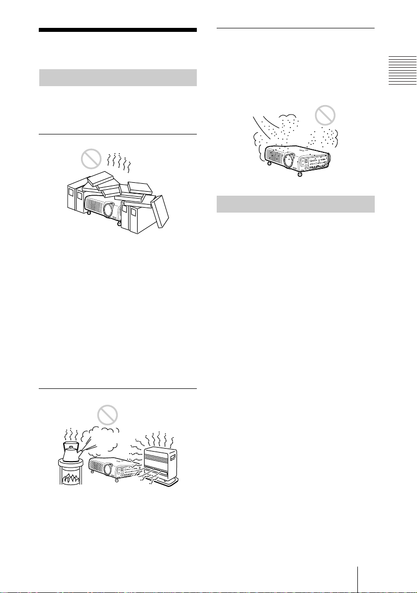
Unsuitable Installation
Do not install the projector in the following
situations. These installations may cause
malfunct ion or damage to the projector.
Poorly ventilated
• Allow adequate air circulation to prevent
internal heat build-up. Do not place the
unit on surfaces (rugs, blankets, etc.) or
near materials (curtains, draperies) that
may block the ventilation holes.
• When the internal h eat builds up due to the
block-up, the temperature sensor will
function with the message “High temp.!
Lamp off in 1 min.” Th e power will be
turned off automatically after one minute.
• Leave space of more than 30 cm (11
inches) around the unit.
• Be careful that the ventilation holes may
inhale tininess such as a piece of paper.
7
/8
Very dusty
Avoid installing the un it in a locatio n where
there is a lot of dust ; o therwise , the air filter
will be obstructed. The dust blocking the air
through the filter may cause raising the
internal heat of the projector . Clean it up
periodically.
Usage in High Altitude
When using the projector at an altitude of
1,500 m or higher, t ur n on “High
Altitude Mode” in the INSTALL S ETTING
menu. Failing to set this mode when using
the projector at high altitudes could have
adverse effects, such as reducing
the reliability of certain components.
Overview
Highly heated and humid
• Avoid installing the unit in a location
where the temperature or humidity is very
high, or temperature is very low.
• To avoid moisture condensation, do not
install the unit in a location where the
temperature may rise rapidly.
Notes on Installation
GB
7
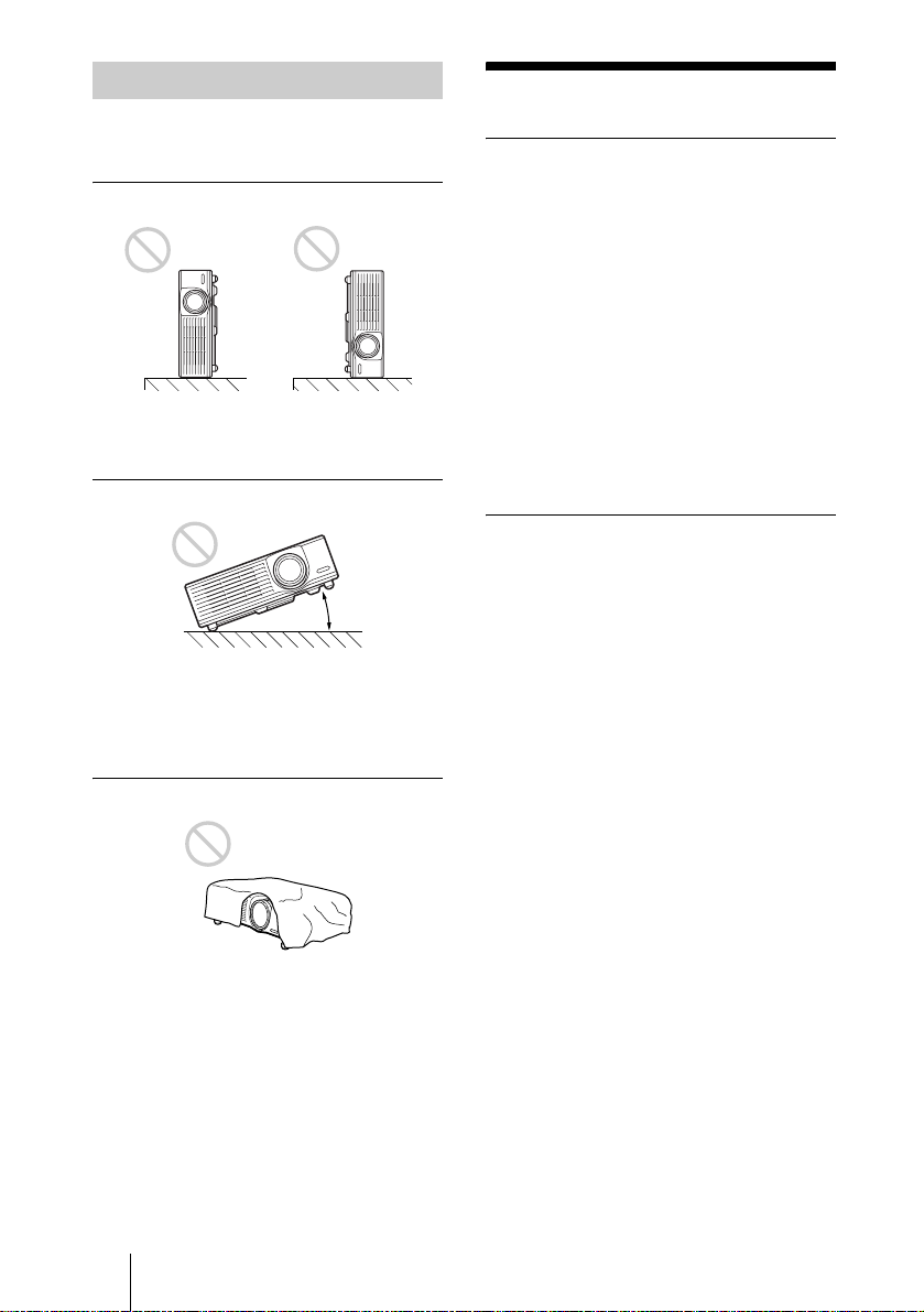
Unsuitable Conditions
Do not use the pr ojector unde r the follo wing
conditions.
Toppling the unit.
Avoid using as the unit topples over on its
side. It may cause mal function.
Tilting right/left
20°
Avoid using as the unit tilts more than 20
degrees. Do not install the unit other than on
the floor or ceiling. These installations may
cause malfunction.
Blocking the ventilation holes
Avoid using something to cover over the
ventilation holes (exhaust/inta k e);
otherwise, the internal heat may build up.
Features
High brightness, high picture
quality
• High brightness
This projector is equi pp e d with a highefficiency optical system made possible
by adopting Sony’s new proprietary
optical system. In addition, this projector
can reproduce bright images of 3500
ANSI lumens, thanks to a newly
developed high numeric aperture LCD
panel with a microlens, and a UHP lamp.
•High resolution
Three 0.99-inch, about 790,000 pixel,
XGA panels provide a resolu tio n of 10 24
× 768 dots for RGB input an d 75 0
horizontal TV lines for video input.
Easy Setup
• Permits setup on a front-to-back slope
This projector can be set up on a slope of
up to 90 degrees up or do wn. The
projector also permits rear projection
using a mirror.
• Optional lenses
The projector can be adapted to a variety
of different type s o f installations by us in g
one of two lenses (sold sepa r a te ly ), one
with a short focus and one with a long
focus.
• Direct Power On/Power Off function
The AC power for the entire system can be
turned on and off by means of a breaker or
other switch.
• System expandability (network
compatibility)
In addition to conventional serial control
using an RS-232C conn e ctor, this
projector also supports connection to an
network environment through an Ethernet
connector. This function can be used to
control multiple proj ectors and also makes
it possible to acquire status information
from each projector, such as the length of
time the lamp has been on.
GB
8 Features
(For details on the network f un ct ion s ,
contact your dealer or the Sony customer
service.)

Convenient presentation functions
• Equipped with USB connector
Simply by connecting the projector to a
computer through the USB interface, the
Remote Commander provided with the
projector can then be used as a wireless
mouse.
• Remote Commander with laser pointer
The Remote Commander comes equipped
with a laser pointer that is useful when
making presentations.
Accepts various input signals
• Equipped with DVI connector and
5BNC connector
The projector is equipped with a DVI-D
connector that can be used to conne ct a
digital RGB device.
The projector is also equipped with a
5BNC input connector that supports highprecision signal connection wit h a
workstation or other device, as well as
long-distance transmission.
• Scan converter loaded
This projector has a build-in scan
converter that converts the input signal
within 1,024 × 768 dots.
• Compatible input signals
This projector accepts video signals of
composite, S video, and component as
well as 15k RGB, VGA, SVGA, XGA,
SXGA, SXGA+ and UXGA (60 Hz)
signals, which all can be display ed. In this
projector, 46 types of input signals are
preset.
• Compatible with six color systems
NTSC, PAL, SECAM, NTSC
4.43
1)
, PALM, or PAL-N color system can be selected
automatically or manually.
1)NTSC4.43 is the color system used when
playing back a video recorded on NTSC
on a NTSC
...............................................................................
4.43 system VCR.
• Windows is a registered trad emark of
Microsoft Corporation in th e United States
and/or other coun tries.
• IBM PC/AT, VGA, SVGA, XGA, SXGA
and UXGA are registered trademarks of
the International Business Machines
Corporation, U.S.A.
• Kensington is a registered trademark of
Kensington Technol ogy Group.
• Macintosh is a registered trademark of
Apple Computer, Inc.
• VESA is a registered trademark of Vid eo
Electro nics Standa r d Associat i on .
• Display Data Channel is a trademark of
Video Electronics Standard Asso c i a tio n.
Overview
Features
GB
9
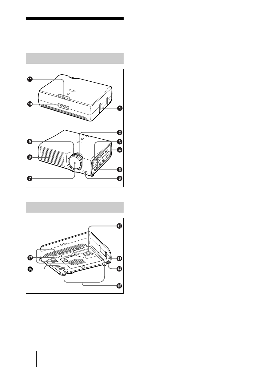
Location and
Function of Controls
Front/Lef t Side
a Handle
b Zoom ring
Adjusts the picture size.
c Control panel
For details, see “Control Panel” on
page 12.
d Connector panel
For details, see “Connector Panel” on
page 13.
e AC IN socket
Connects the supplied AC power cord.
f Front remote control detector
g Lens
Remove the lens cap before projection.
h Ventilation holes (exhaust)
i Focus ring
Adjusts the picture focus.
j Rear remote control detector
Rear/Right Side/Bottom
GB
10 Location and Function of Controls
k Indicators
• LAMP/COVER: Lights up or flashes
under the following conditions:
– Lights up when the lamp has
reached the end of its life or
becomes a high temperature.
– Flashes when the lamp cover or air
filter cover is not secured firmly.
• TEMP (Temperature)/FAN: Lights
up or flashes under the following
conditions:
– Lights up when temperature inside
the projector becomes unusually
high.
– Flashes when the fan is broken.
For details on the LAMP/COVER and
the TEMP/FAN indicators, see on
page 43.
• POWER SAVING: Lights up when
the projector is in power savi ng mode.
When POWER SAVING in the SET
SETTING menu is set to ON, the
projector goes into power saving mode
if no signal is input for 10 minutes.
Although the lamp goes out, the
cooling fan keeps running. The power
saving mode is canceled when a signal
is input or any key is pre ssed. In power
saving mode, any key doe s not
function for the first 60 seconds after
the lamp goes out.
• ON/STANDBY: Lights up or flashes
under the following conditions:
– Lights in red when a AC power cord
is plugged into a wall outle t. Once in
standby mode, yo u ca n turn on the
projector with the I / 1 key.
– Lights in green when the power is
turned on.
– Flashes in green while the cooling
fan runs after the power is turned off
with the I / 1 key. The fan runs for
about 90 seconds after the power is
turned off.
The ON/STANDBY indicator
flashes quickly for the first 60
seconds. During this time, you
cannot light up the ON/STANDBY
indicator w ith the I / 1 key.
Note
• To maintain optimal performance, clean
the air filter every 1500 hours.
For details, see “Cleaning the Air
Filter” on page 39.
Overview
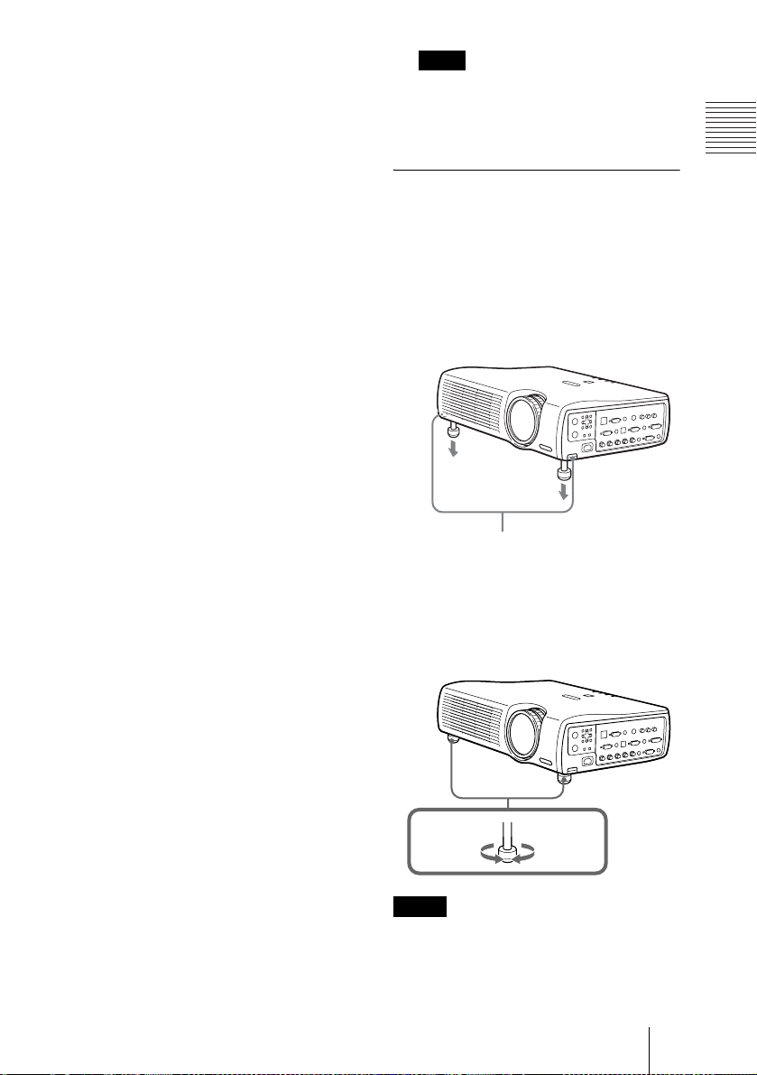
How to use the adjuster
To adjust the height
Adjusts the height of the projector as
follows:
1 Lift the projector and press the
adjuster adjustment buttons.
The adjusters will extend from the
projector.
l Lamp cover
m Security lock
Connects to an optional security cable
(Kensington’s).
Home page address:
http://www.kensington.com/
n Adjuster adjustment buttons
For details, see “How to use the
adjuster” on pag e 11 .
o Adjuster
p Speaker
q Ventilation holes (intake)/air
filter cover
• Do not place anything near the
ventilation holes as it may cause
internal heat build-up.
• Do not place your hand or objects near
the ventilation holes as it may cause the
air coming out heat bui l d- up.
Adjuster adjustment buttons
2 While pressing the buttons, adjust the
projector to the desired height, and
then release the buttons. For fine
adjustment, turn the adjusters to the
right and the left.
to lower
the
projector
Notes
• Be careful not to le t the projector down on
your fingers.
• Do not push hard on the top of the projector
with the adjust er s out.
It may be occurred malfunction.
Location and Function of Controls
to raise the
projector
11
GB
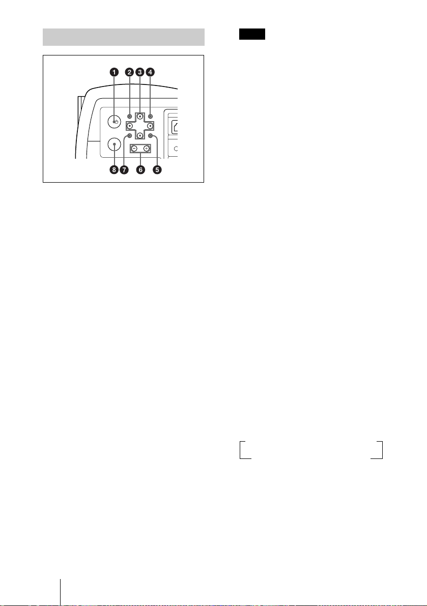
Control Panel
U
H
APAMENU
CONT
I/
VOLUME
INPUT
a I / 1 (on/standby) key
Turns on and off the projector when the
projector is in standby mode. The ON/
STANDBY indicator lights in green
when the power is turned on.
When turning off the power, press
the I / 1 key twice following the
message on the screen, or press and
hold the key for about one second.
For details on steps for turning off the
power, see “To turn off the power” on
page 28.
b MENU key
Displays the on-screen menu. Press
again to clear the menu.
c Arrow keys (M/m/</,)
Used to select the menu or to make
various adjustments.
d APA (Auto Pixel Alignment) key
Pressing this key while a signal from a
computer is being input automatically
adjusts the picture so that it can be seen
clearly. This function also
simultaneously adjusts th e screen size
and makes up/down and left/right shift
adjustments.
ET
RESETENTER
INP
Note
Press the APA k ey when the full im age is
displayed on the scr een. If the projected
image includes a large black area aro und
the periphery, th e A PA function will no t
function properly and in some cases,
portions of the ima ge m ay not be
displayed.
• You can cancel t he adjustment by
pressing the APA ke y again while
“Adjusting” appea rs on t he screen.
• The picture may not be adjusted properly
depending on the kinds of input signals.
• Adjust the item s “D ot Phase,” “H Size”
and “Shift” in the INPUT SETTING
menu when you adju st the picture
manually.
e RESET key
Resets the value of an item back to its
factory preset value. This key functions
when the menu or a setting item is
displayed on the screen.
f VOLUME +/– key
Adjusts the volume of the built-in
speakers and output level of the AUDIO
jack.
+:Increases the volume.
–:Decreases the volume.
g ENTER key
Enters the settings of items in the menu
system.
h INPUT key
Selects the input signal. Each time you
press the key, the input signal switches
as follows:
t INPUT A t INPUT B t INPUT C t
S VIDEO T VIDEO T INPUT D
The audio signals are common to the
INPUT B, INPUT C, VIDEO and
S-VIDEO.
GB
12 Location and Function of Controls
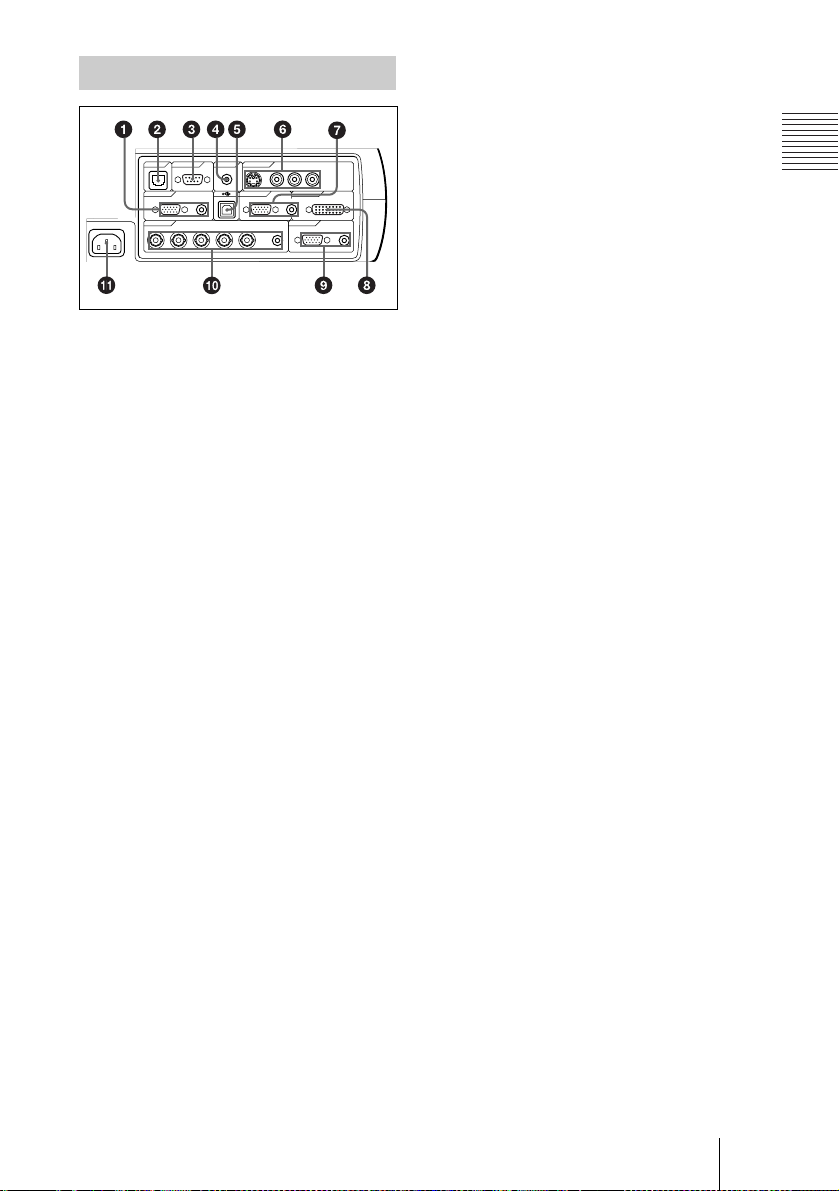
Connector Panel
VOLUME
~AC IN
INPUT D OUTPUT
INPUT A INPUT B INPUT C
ETHER
(PLUS IN POWER)
(MONO)
LR
RS-232C IN S VIDEO VIDEO AUDIO
RGB AUDIO RGB DVI-D
R/R-Y/Pn G/Y B/B-Y/Ps SYNC/HD VD AUDIO MONITOR AUDIO
AUDIO
ENTERMENU
RESETAPA
CONTROL
REMOTE VIDEO IN
CONTROL S
a INPUT A connectors
Connect to a computer.
• HD D-sub 15-pin, female:
Connect to the monitor output on a
computer using the supplied cable.
• AUDIO (stereo mini-jack): Connects
to the audio output on a computer.
b ETHER (RJ-45)
Connects to the LAN cable when the
network function is in use.
Consult the dealer for connection and
installation.
c RS-232C connector (D-sub 9-
pin, female)
Connects to a computer to operate the
projector from the computer.
d CONTROL S IN/PLUG IN
POWER (DC 5V output) jack
Connects to the control S out jacks of the
Sony equipment. Connects to the
CONTROL S OUT jack on the supp lied
Remote Commander when using it as a
wired Remote Commander. In th is case,
when a stereo cable is used, you do not
need to install the batteries in the
Remote Commander, since the power is
supplied from this jack.
e USB connector (USB plug for
upstream, 4-pin)
Connects to the USB connector on a
computer. When you connect the
projector to the computer, you can
control the mouse function with the
supplied Remote Commander.
f Video input connectors
Connect to external video equipment
such as a VCR.
• S VIDEO (mini DIN 4-pin):
Connects to the S video output (Y/C
video output) of video equipment.
• VIDEO (phono type): Connects to
the composite video output of video
equipment.
• AUDIO input L (MONO)/R (phono
type): Connect to the audio output of
equipment. For stereo equ ipment, use
both the L and R jacks; for monaural
equipment, use the L (MON O) jack
only.
g INPUT B connectors
Connect to a computer.
• HD D-sub 1 5 -pin, female:
Connects to the monitor output on a
computer using the su pp lie d ca b le .
• AUDIO (stereo mini-jack)/Shared
by INPUT B and C: Connects to the
audio output on a compu ter.
h INPUT C connector (RGB (DVI))
(DVI-D)
Connects to a computer equipped with
DVI (digital) output connector with a
DVI cable.
i OUTPUT connectors
MONITOR (HD D-sub 15-pin,
female):
Connect to t he video inpu t co nne ctor on
the monitor. Outputs signals from the
selected cha nnel and computer signals
only from among the signals from the
INPUT A, INPUT B, or INPUT D RGB
connector. Thi s connector does not
output any signals from the INPUT C
connector.
• AUDIO (stereo mini-jack): Connects
to external active speakers. The
volume of the speakers can be
controlled by the VOLUME +/– keys
on the Remote Commander or the
VOLUME +/– keys on the control
panel.
Location and Function of Controls
13
Overview
GB
j INPUT D, 5BNC input
connectors (R/R-Y/P
B, SYNC/HD, VD connectors)
Y/P
R, G/Y, B/B-
(BNC type):
Connect to a high-resolution computer
or VCR where signals are transmitted
long distances; for example, when the
projector has been hung from the
ceiling.
According to the connected equipment,
computer, component (R-Y/Y/B-Y),
HDTV or DTV (DTV GBR, DTV
BPR) signal is selected.
YP
• AUDIO (stereo mini-jack): Connects
to the audio output on a computer.
k AC IN socket
Connects the supplied AC power cord.
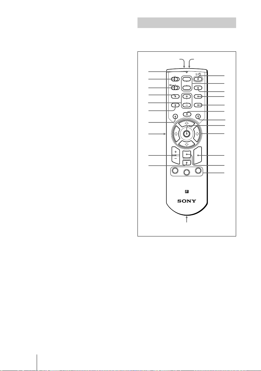
Remote Commander
The keys which have the sa m e nam es as on
the control panel function identically.
wf
wd
ws
wa
w;
ql
qk
qj
qh
qg
wg
COMMAND
OFF
PJ NETWORK
LENS
APA
MENU/
TAB
D ZOOM
1
ON
PROJECTOR
PIC
MUTING
AUDIO
VOLUME
FREEZE
ENTER
RESET/
ESCAPE
2
FUNCTION
RM-PJM15
wh
INPUT
D KEYSTONE
HELP
LASER
R
CLICK
3
1
2
3
4
5
6
7
8
9
q;
qa
qs
GB
14 Location and Function of Controls
qd,qf
a I / 1 key
b MUTING keys
Cut off the picture and sound.
• PIC: Cuts off the picture . P ress again
to restore the picture.
• AUDIO: Press to temporarily cut off
the audio output from the speaker, and
the output on the AUDIO jack in the
OUTPUT section.
Press again or pr e s s the V O LU ME +
key to restore the sound.
c INPUT key

d D KEYSTONE key
Corrects the trapezoidal distortion
caused by the projection angle. Use the
arrow keys (M/m/</,) to display the
image as a rectangle.
e HELP key
This function is not provided in this
projector.
f FREEZE key
This key freezes the projected image.
Press again to unfreeze the image.
p D ZOOM +/– key
Enlarges the image at a desired location
on the screen.
+: Pressing the + key once displays the
icon. This icon indicates the poin t you
want to enl arge. Us e an arrow key (M/
m/</,) to move the icon to the
point to be enlarged. Press the + key
repeatedly until the image is enl arged
to your requirements.
–: Pressing the – key reduces an image
that has been enlarged with the D
ZOOM + key.
Overview
g LASER key
Emits laser beam from the laser
transmitter when you press this key.
h Joy stick
Functions as a mouse of a computer
connected to the unit.
i Arrow keys (M/m/</,)
j R CLICK key
Functions as a right button on a mouse of
a computer connected to the unit.
k ENTER key
l FUNCTION 1/2/3 keys
This key does not wor k in the unit.
m Strap holder
Attaches the supplied strap.
n CONTROL S OUT jack (stereo
mini-jack)
Connects to the CONTROL S IN jack on
the projector with the connecting cable
(not supplied) when using the Remote
Commander as a wired one. In this case,
you do not need to install the batteries
since the power is supplied via the
CONTROL S IN jack on the projector.
o RESET/ESCAPE key
Functions as a RESET key.
q L CLICK key
Functions as a left button on a mouse of
a computer connected to the unit.
r MENU/TAB key
Functions as a MENU key.
s APA (Auto Pixel Alignment) key
t VOLUME +/– keys
u LENS key
This function is not provided in this
projector.
v PJ/NETWORK (Projector/
Network) selector switch
Set this switch to PJ always.
w COMMAND ON/OFF switch
When this switch is set to OFF, no key
on the Remote Commander function.
This saves the battery power.
x Transmission indicator
Lights up when you press a key on the
Remote Commander.
This indicator does not light up when
you use the laser pointer.
y Infrared transmitter
z Laser transmitter
Location and Function of Controls
15
GB
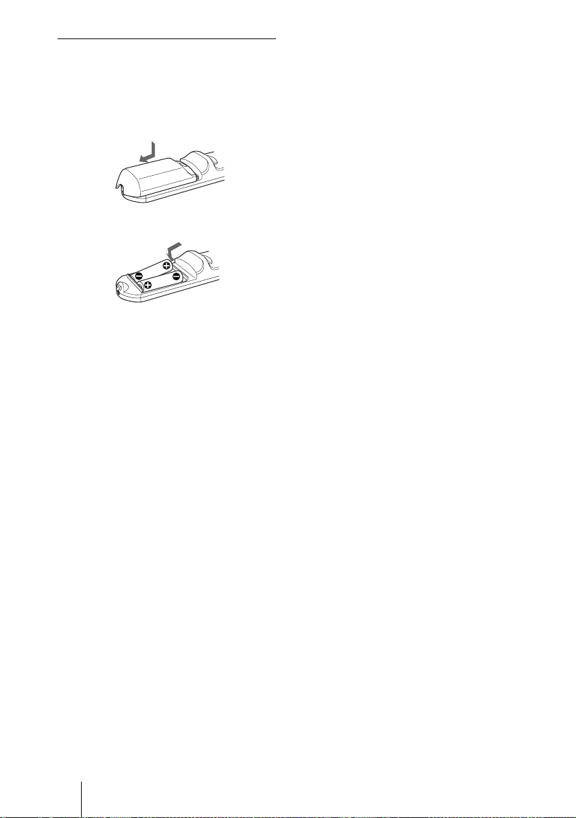
Battery installation
1 Push and slide to open the lid, then
install the two size AA (R6) batteries
(supplied) with the correct polarity.
While pressing the lid, slide it.
Be sure to install the battery
# side.
from the
2 Replace the lid.
Notes on batteries
• Make sure that the battery orientation is
correct when inserting batteries.
• Do not mix an old battery with a new one
or different types of batteries.
• If you will not use the Remote
Commander for a long time, remove the
batteries to avo id damage from battery
leakage. If batteries have leaked, remove
them, wipe and dry the battery
compartment, and replace the batteries
with new ones.
Notes on laser beam
• Do not look into the laser transmitter.
• Do not aim the laser at people.
Notes on Remote Commander
operation
• Make sure that nothing to ob stru ct the
infrared beam be tween the Remote
Commander and the remote control
detector on the projector.
• The operation range is limited. The shorter
the distance between the Remote
Commander and th e projector is , the wider
the angle within which the commander can
control the projector.
GB
16 Location and Function of Controls
B Setting Up and Projecting
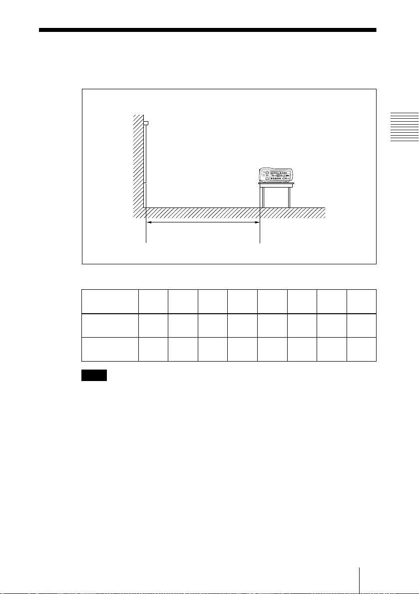
Installing the Projector
This section describes how to install the projector.
The distance between the lens and the screen varies depending on the size of the
screen. Use the following table as a guide.
Distance between the screen and
the center of the lens
Unit: m (ft)
Screen size
(inches)
Minimum
Distance
Maximum
Distance
40 60 80 100 120 150 200 300
1.5
2.3
2.9
3.0
(10.0)
3.8
(12.5)
(4.9)
1.9
(6.2)
(7.5)
(9.5)
3.8
(12.5)
4.8
(15.7)
4.6
(15.0)
5.8
(19.0)
5.8
(19.0)
7.2
(23.6)
7.7
(25.2)
9.7
(31.7)
Setting Up and Projecting
11.6
(37.9)
14.5
(47.6)
Note
For details on ceiling installation, co nsult with qualified S ony personnel.
Installing the Projector
17
GB

Connecting the Projector
When you connect the projector, make sure to:
• Turn off all equipment before making any conne ctions.
• Use the proper cables for each connection.
• Insert the cable plugs firmly; loose connections may increase noise and
reduce performance of picture signals. When pulling out a cable, be sure to
pull it out from the plug, not the cable itself.
To connect the projector, refer to the illustrations on the next and the
following pages.
Connecting with a Computer
This section describes how to connect the projector to a computer.
For more information, refer to the computer’s instruction manual.
Notes
• The projector accepts 15k RGB, VGA, SVGA, XGA, SXGA, SXGA+ and UXGA
(60 Hz) signals. H ow ever, we recommend that you set the output mode of your
computer to XGA mode for the external monitor.
• If you set yo ur computer, such as a not ebook type, to output t he signal to both your
computer’s dis pl ay and the external moni t or, the picture of the proj ector may not
appear properly. Set your computer to output the signal to only the external monitor.
For details, refer to the computer’s operating instructions supplied with your
computer.
• This projector is compatible with a DDC2B (Digital Data Channel 2B). If your
computer is compatible with a DDC, turn t he p rojector on a ccording to t he foll owing
procedures.
1 Connect the projector t o the computer by using th e supplied HD D-sub 15-p in cable
or DVI cable.
2 Turn the projector on.
3 Start the computer.
GB
18 Connecting the Projector
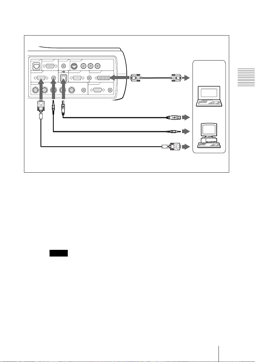
To connect an IBM PC/AT compatible computer
When you use a wireless mouse
Right side
CONTROL
REMOTE VIDEO IN
ETHER
INPUT A INPUT B INPUT C
RGB AUDIO RGB DVI-D
INPUT D OUTPUT
R/R-Y/Pn G/Y B/B-Y/Ps SYNC/HD VD AUDIO MONITOR AUDIO
CONTROL S
RS-232C IN S VIDEO VIDEO AUDIO
(PLUS IN POWER)
AUDIO
LR
(MONO)
DVI cable (not
supplied)
b)
To DVI-D
output
Computer
Setting Up and Projecting
USB cable (supplied)
(Connect the USB cable to use a
wireless m o us e .)
Stereo audio connecting cable (not supplied)
HD D-sub 15-pin cable (supplied)
a) Use a no-resistance ca bl e .
b) Connect a DVI cable to use a DVI equipment.
On the USB function
When connecting the projector to a computer by using the USB cable for the
first time, the computer recognizes the following devices automatically.
USB human interface device (wireless mouse function)
Recommended operating environment
When you use the USB function, connect your computer as illustrated above.
The USB mouse function can be used on a computer that came with Windows
98, Windows 98 SE, Windows ME, Windows 2000 or Windows XP
preinstalled models.
Notes
• Your computer may not start correctly when connected to the projector via the USB
cable. In thi s case, disconnect the USB cable , restart the computer, then connect the
computer to the projector using the USB cable.
• This projector is not guaranteed for suspen d, st andby mode. When y ou use the
projector in suspend, standby mode, di sconnect the project or from the USB port on
the computer.
• Operatio ns are not guaranteed for all the recommended computer env ir onments.
to USB connector
a)
to audio output
to monitor output
Connecting the Projector
19
GB
To connect a Macintosh computer
W
To connect a Macintosh computer equipped with video output connector of a
type having two rows of pins, use a commercially available plug adaptor.
When you connect a USB capable Macintosh computer using the USB cable
to the projector, wireless mouse functions become available.
Connecting with a VCR or 15k RGB/Component Equipment
This section describes how to connect the projector to a VCR and 15k RGB/
component equipment.
For more information, refer to the instruction manuals of the equipment you
are connecting.
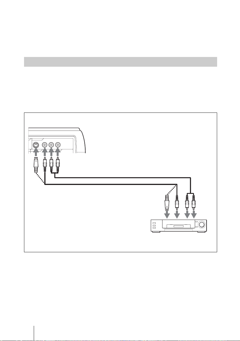
To connect a VCR
Right side
VIDEO IN
S
S VIDEO VIDEO AUDIO
ER)
INPUT B INPUT C
LR
(MONO)
-
Audio connecting cable (not s upplied)
Video cable (not supplied) or
S-Video cable (not supplied)
For stereo equipment, use both the L and R jacks.
For monaural equipment, use the L (MONO) jack only.
to video output
to S video
output
to audio
output
VCR
GB
20 Connecting the Projector
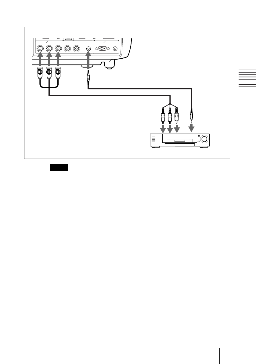
To connect a 15k RGB/Component equipment
Right side
INPUT D OUTPUT
R/R-Y/Pn G/Y B/B-Y/Ps SYNC/HD VD AUDIO MONITOR AUDIO
BNC cable (not supplied)
a) Use a no-resistance cable.
Notes
• When you connect the unit to 15k RGB or component video equipment, select video
GBR or component with the Input-D Signal Sel. setting in the SET SETTING menu.
• Use the com posite sync signal wh en you input the exter nal sync signal from 15k
RGB/component equi pm ent.
Stereo audio connecting cable
(not supplied)
a)
to RGB/
component
output
15k RGB/Component equipment
Setting Up and Projecting
to audio
output
Connecting the Projector
21
GB
Selecting the Menu Language
You can select one of nine languages for displaying the menu and other onscreen displays. The factory setting is English.
Front remote
COMMAND
OFF
PJ NETWORK
LENS
APA
MENU/
TAB
ON
PIC
MUTING
AUDIO
INPUT
D KEYSTONE
VOLUME
HELP
LASER
FREEZE
control detec t or
I/
APAMENU
RESETENTER
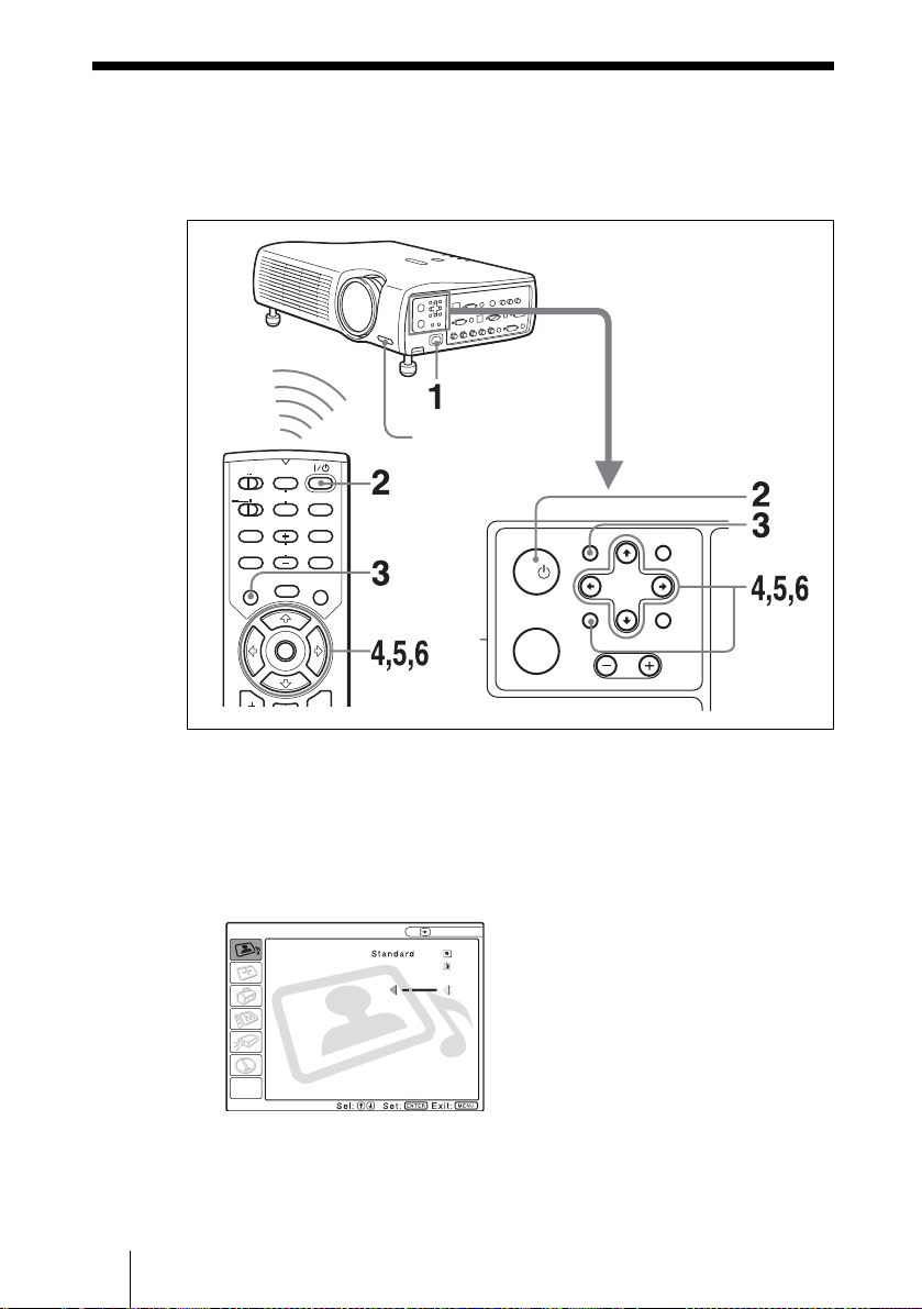
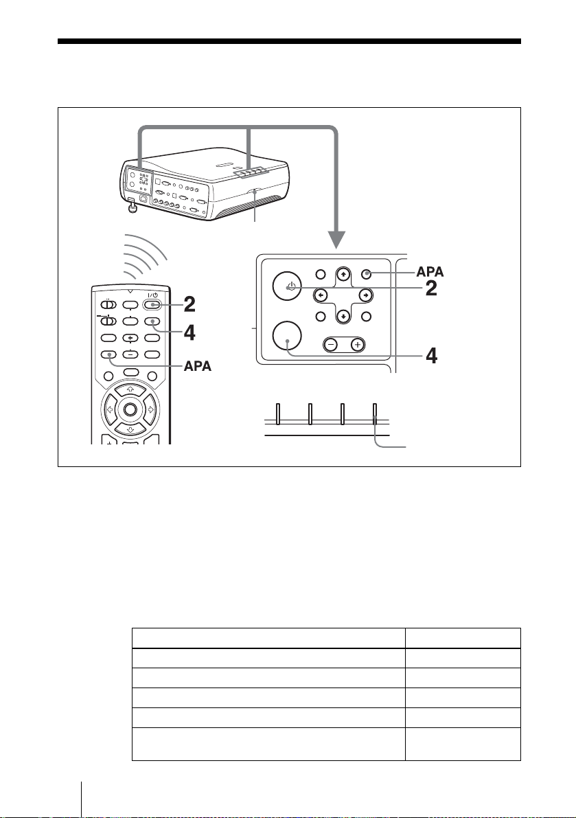
1 Plug the AC power cord into a wall outlet.
2 Press the I / 1 key to turn on the projector.
3 Press the MENU key.
The menu appears.
The menu presently selected is shown as a yellow button.
PICTURE SETTING
Picture Mode:
Adjust Picture...
Volume: 30
GB
22 S electing the Menu Language
Input A
INPUT
VOLUME
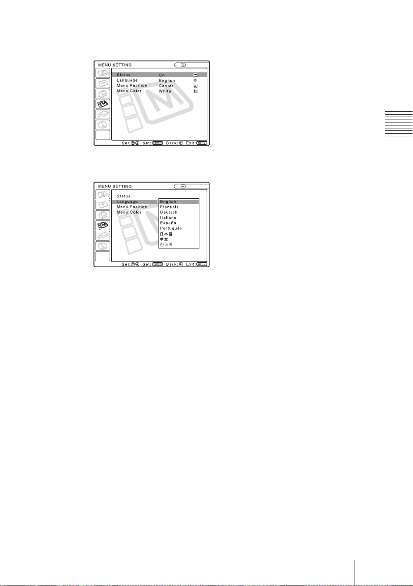
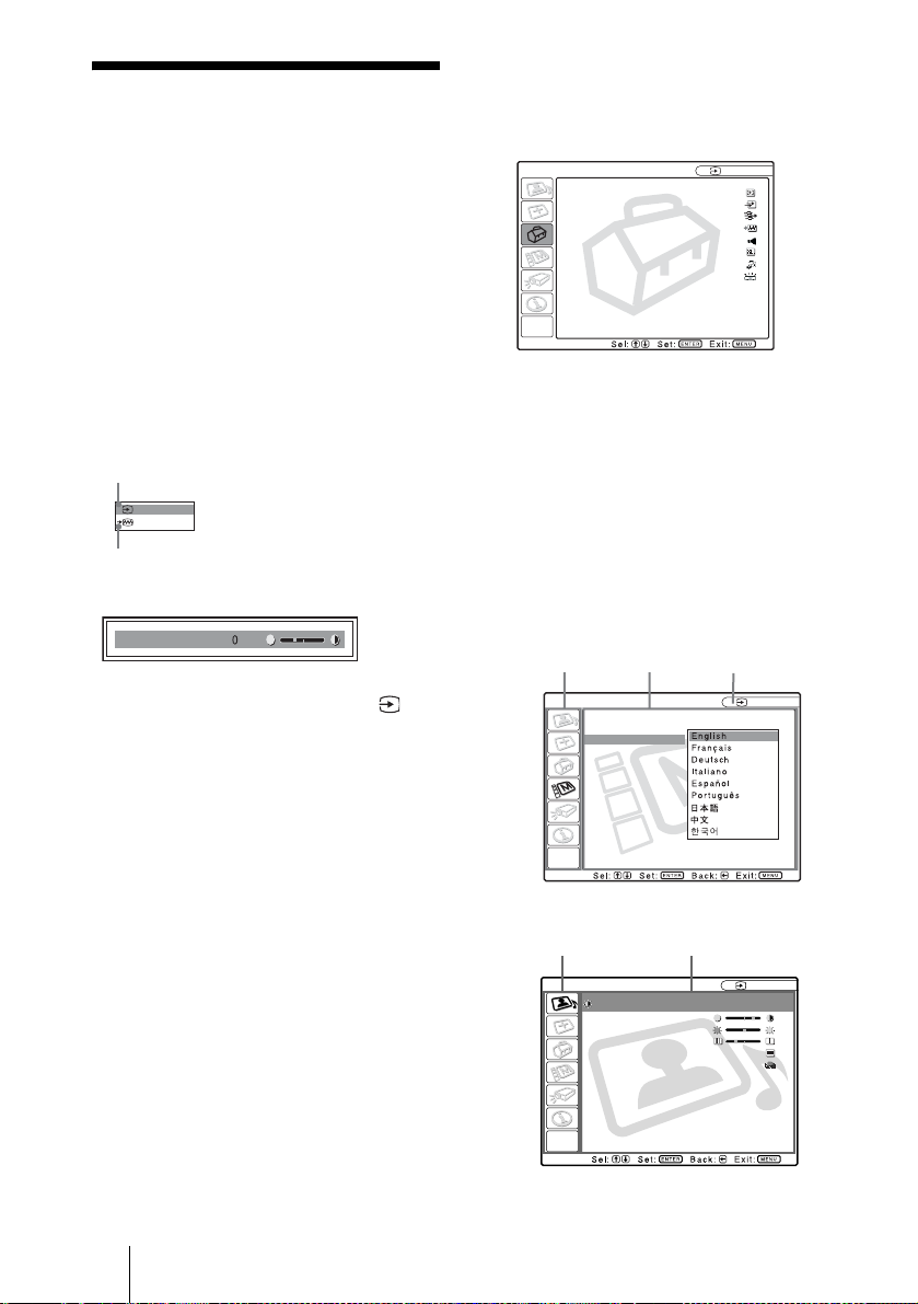
4 Press the M or m key to select the MENU SETTING menu, then press the
, or ENTER key.
The selected menu appears.
Input A
:
:
:
:
A
5 Press the M or m key to select “Language,” then press the , or ENTER
key.
:
:
:
:
Input A
6 Press the M or m key to select a language, then press the < or ENTE R
key.
7 The menu changes to the selected language.
Setting Up and Projecting
To clear the menu
Press the MENU key.
The menu disappears automatically if a key is not pressed for one minute.
Selecting the Menu Language
23
GB
Projecting
COMMAND
ON
OFF
PIC
PJ NETWORK
MUTING
AUDIO
INPUT
D KEYSTONE
LENS
VOLUME
MENU/
APA
TAB
FREEZE
HELP
LASER
Rear remote control
detector
I/
INPUT
LAMP/
COVER
TEMP/
FAN
VOLUME
POWER
SAVING
APAMENU
RESETENTER
STANDBY
ON/
ON/STANDBY
indicators
GB
24 Projecting
1 Plug the AC power cord into a wall outlet, then connect all equipment.
The ON/STANDBY indicator lights in red and the projector goes into
standby mode.
2 Press the I / 1 key.
The ON/STANDBY indicator lights in green.
3 Turn on the equipment connected to the projector.
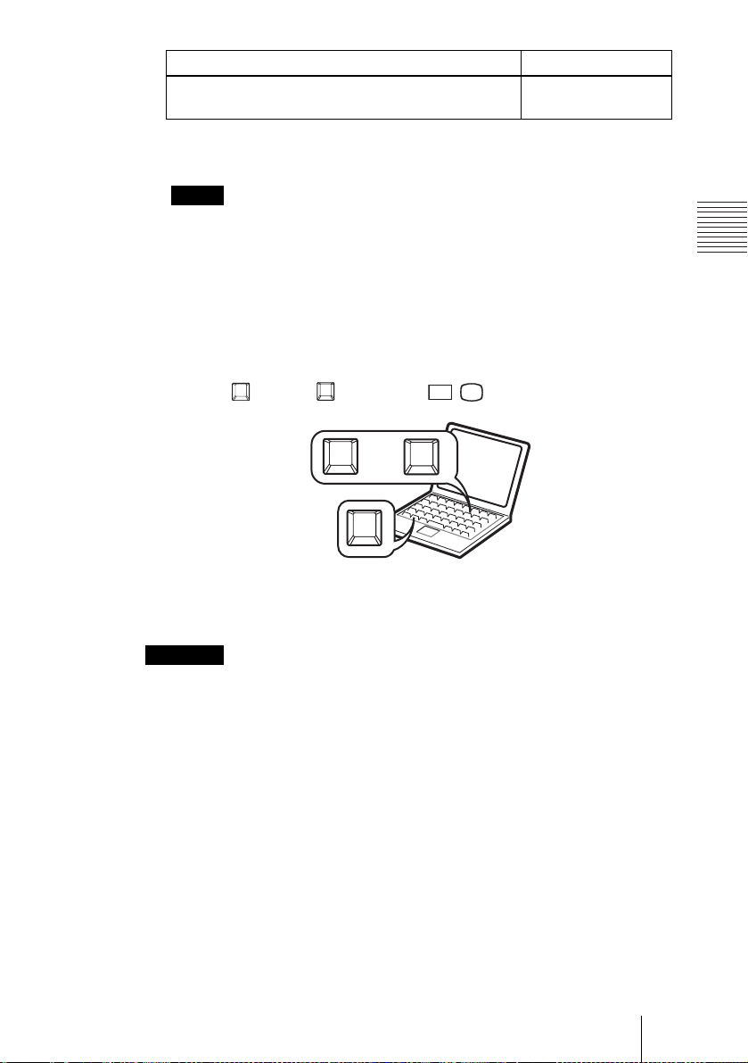
4 Press the INPUT key to select the input source.
To input from Press INPUT to display
Computer connected to the INPUT A connector INPUT A
Computer connected to the INPUT B connector INPUT B
Computer connected to the INPUT C (digital) connector INPUT C
Computer connected to the INPUT D connector INPUT D
Video equipment connected to th e V I D E O in put
connector
VIDEO
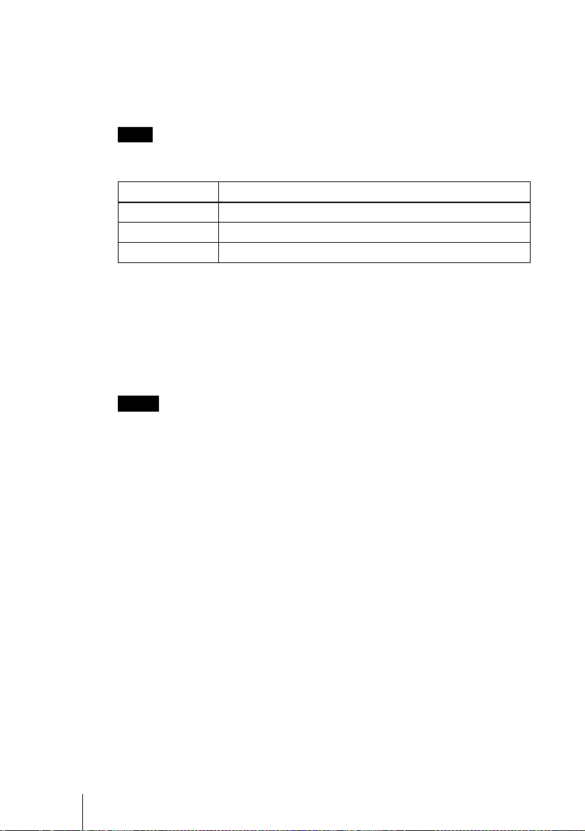
To in put fro m Press INPUT to display
Video equipment conne cted to the S VIDEO input
connector
S VIDEO
Smart APA (Auto Pixel Alignment) adjusts the picture of the connected
equipment so that it is pr ojected clearly.
Notes
• If “Auto Input Search” is set to “On”, the projector searches for the signals from
the connected equi pment and displays th e i nput channel where t he input signals
are found.
For details, see “Auto Input Se arch” in the SET SETTING menu on page 35.
• The smart APA is effective for the input signal from a computer only.
When the projector is connected to a notebook or a computer with a built-in
LCD screen, you may have to switch the comp uter to outpu t to the projector b y
pressing key and key (such as .)
Fn
Fx
or
F7
Fx
LCD
VGA
/
Fn
Setting Up and Projecting
5 Turn the zoom ring to adjust the size of the picture.
6 Turn the focus ring to adjust the focus.
Attention
Looking into the lens when projec t ing may cause injur y to your eyes.
To adjust the volume
The volume can be adjusted in the on-screen menu. See “Volume” in the
PICTURE SETTING menu on page 33.
To mute the picture
Press the PIC MUTING key on the Remote Commander. Press again to restore
the picture.
Projecting
25
GB
To control the computer using the supplied Remote Commander
When you connect an IBM PC/AT compatible to the projector by using the
USB cable, you can control the mouse of the computer using the Remote
Commander.
The R/L CLICK keys and joystick function as follows.
Note
Make sure that nothing obstructs the infrared beam between the Remote Commander
and the remote control detector on the projector.
Key and joystick Function
R CLICK (front) Right butt on
L CLICK (rear) Left button
Joystick Corresponds with the movements of the mouse
To get the clearest picture
You can adjust picture quality when projecting a signal from the computer.
1 Project a still picture from the computer.
2 Press the APA key.
“Complete!” appears on the screen when the picture is adjusted properly
Notes
• Press the APA ke y when the full image is displayed on the screen. If the projected
image includes a large black area aro und the periphery, th e A PA function will n ot
function properly and in some cases, portions of the image may not be displayed.
• When you switch the i nput si gnal o r re-co nnect a comput er, pres s the APA ke y agai n
to adjust the picture again.
• You can cancel the adjustment by pressing the APA key again while “ADJUSTING”
appears on the screen.
• The picture may not be adjusted properly dependin g on the kinds of inpu t signals.
• Adjust the items in the INPUT SETTING menu when you adjust the picture manually.
.
Using the security lock
1 Press the MENU key and then, in the INSTALL SETTING menu, turn on
the security lock setting.
2 Enter the password.
Use the MENU,
password. (The default setting is
GB
26 Projecting
M/m/</,, and ENTER keys to enter the four-digit
“ENTER, ENTER, ENTER, ENTER.”)
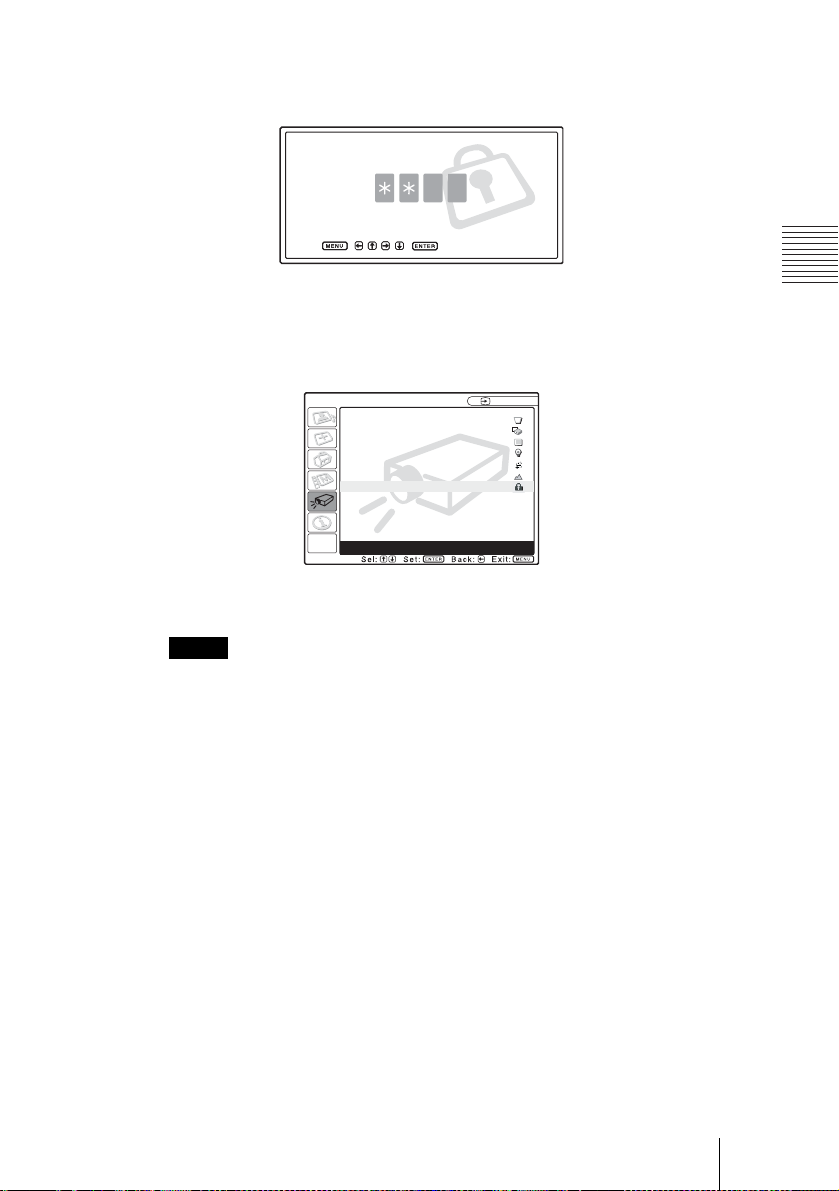
Next, the screen for entering the new password is displayed. (Enter the
password at this screen even if you want to keep the current password.)
Enter password key
Use: Cancel: Other key
3 Enter the password again to confirm.
If the password is entered incorrectly, the menu screen displays an
Password
” message.
INSTALL SETTING
V Keystone: 0
Image Flip: Off
Background: Blue
Lamp Mode: Standard
Direct Power On: Off
High Altitude Mode
Security Lock: Off
Invalid Password!
: Off
Input A
X
4 The security lock is completed.
Setting Up and Projecting
“Invalid
Notes
• You will not be able to use the projector if you forget your password and the password
administrator is not available. Be please aware that using the security lock can prevent
valid usage in su ch cases. It is recommended that you make a note of the selected
password.
• Once the security lock is set and the main power is turned off, the screen for entering
the password is displayed when the power is turned on the next time. Enter the
password that was set. If you fai l to enter the correct p assword af ter three tr ies, the
projector cann ot be used. In this case , pre ss the I / 1 key to turn off the power.
• The security lock will not be set if the correct password is not entered in steps 2 and
3, or a key other tha n th e MEN U , arrow keys, and ENT ER key is pressed.
• If you call the customer service center because you have forgotten the password, you
will need to be able to verify the projector’s serial number and your identity. (This
process may differ in other countries.) Once your identity has been confirmed, we
will provide you with the password.
Projecting
27
GB

To turn off the power
1 Press the I / 1 key.
“POWER OFF? Please press I / 1 key again.” appears to confirm that you
want to turn off the power.
Note
A message disappears if you press any key except the I / 1 key, or if you do not
press any key for f ive seconds.
2 Press the I / 1 key again.
The ON/STANDBY indicator flashes in green and the fan continues to run for
about 90 seconds to reduce the internal heat. Also, the ON/STANDBY
indicator flashe s quickl y for the first 60 seconds . During this tim e, you will not
be able to light up the ON/STANDBY indicator with the I / 1 key.
3 Unplug the AC power cord from the wall outlet after the fan stops running
and the ON/STANDBY indicator lights in red.
When you cannot confirm the on-screen message
When you cannot confirm the on-screen message in a certain condition, you can
turn off the power by holding the I / 1 key for abo ut on e s ec o nd .
Note
The internal circuitry of the Direct Power On/Off function may cause the fan to continue
to operate for a short time even after the I / 1 key is pressed to turn o ff th e power and
the ON/STANDBY indicator changes to red.
Direct Power On/Off function
If you will be using a circuit breaker to turn the power for the entire system on an d off,
set the direct power on function to “On”. When you turn off the power, you can also just
unplug the pow er c or d wi tho ut p res si ng the I / 1 key. The internal circuitry will cause
the fan to automatically operate for a certai n time even after the power cord is removed.
However, if the unit has been on for less than 15 minutes, the fan might not begin to turn
as a result of inadequate charging. In that case, follow the procedure for turning off the
power as desc ri bed in “To turn off the power”.
On air filter
To maintain optimal performance, clean the air filter every 1500 hours.
We recommend that you clean the air filter whenever you replace the lamp,
even if 1500 hours have not elapsed since the last time the air filter was
cleaned.
Effective Tools for Your Presentation
To enlarge the image (Digital Zoom function)
You can select a point in the image to enlarge. This function works when a
signal from a computer is input.
GB
28 Projecting
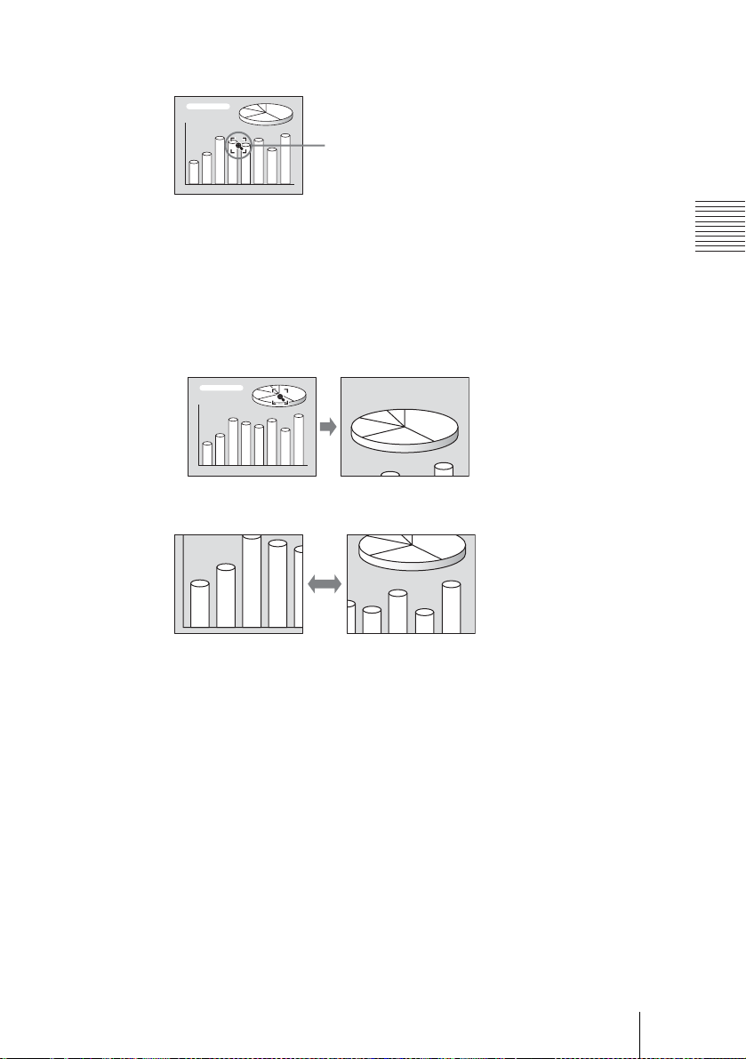
1 Press the D ZOOM + key on the Remote Commander.
The digital zoom icon appears the center of the image.
Digital zoom icon
2 Move the icon to the point on the image you want to enlarge. Use the arrow
key (M/m/</,) to move the icon.
3 Press the D ZOOM + key again.
The image where the icon is located is enlarged. The enlargement ratio is
displayed on the screen for a few seconds.
By pressing the + key repeatedly, the image size increases (ratio of
enlargement: max. 4 times.)
Use the arrow key (M/m/</,) to scroll the enlarged image.
Setting Up and Projecting
To return the image back to its original size
Press the D ZOOM – key.
Just pressing the RESET key returns the image back to its original size
immediately.
To freeze the image projected (Freeze function)
Press the FREEZE key. “FREEZE” appears when the key is pressed. This
function works when a signal from a computer is input.
To restore the original screen, press the FREEZE key again.
To use the Laser Pointer function
Press the LASER key on the Remote Commander to shine the laser pointer.
The pointer is helpful in indicating a particular point on the screen.
Projecting
29
GB
B Adjustments and Settings Using the Menu
1 Press the MENU key.
Using the MENU
The projector is equipped with an on-screen
menu for making various adjustments and
settings. The setting items are d isplayed in a
pop-up menu or in a sub menu. If yo u select
an item name followed by dots (...), a sub
menu with setting items appear. You can
change the tone of the menu display and the
menu language displa ye d in the on - s cre e n
menu.
To change the menu langu age, see
“Selecting the Menu Language” on page 22.
Display items
Input signal indicator
The menu appears.
The menu presently selected is shown as
a yellow button.
SET SETTING
Smart APA:
Auto Input Search:
Input-D Signal Sel:
Color System:
Speaker:
Power Saving:
IR Receiver:
Illumination:
2 Use the M or m key to select a menu,
then press the , or ENTER key.
The selected menu appears.
3 Select an item.
Video
NTSC 4.43
Input signal setting indicator
Picture adjustment menu
Contrast
Input signal indicator
Shows the selected input channel. is
x
displayed when no signal is input. You can
hide this indicator using “Status” in the
MENU SETTING menu.
Use the M or m key to select the item,
then press the , or ENTER key.
The setting items are displayed in a pop up menu or in a sub menu.
Pop-up menu
Setting items
Menu
MENU SETTING
Status:
Language:
Menu Position:
Menu Color:
Input A
On
Off
Computer
Auto
On
Off
Front&Rear
On
Selected input
signal
Input A
Input signal setting indicator
For Input D: Shows “Computer”,
“Component” or “Vid eo GB R”.
GB
30 Using the MENU
Sub menu
Menu Setting items
PICTURE SETTING
ADJUST PICTURE
Contrast: 80
Brightness: 50
RGB Enhancer: 30
Gamma Mode:
Color Temp:
Standard
Graphics
High
Input A
 Loading...