

Page 1
Video Projector VPL-HS3
4-099-552-11 (1)
Video Projector
Operating Instructions __________________________________
Mode d’emploi ______________ ___ ______________ __ __ ___ __
Manual de instrucciones _________________________________
GB
FR
ES
VPL-HS3
© 2003 Sony Corporation
Page 2
WARNING
To prevent fire or shock hazard, do not expose
the unit to rain or moisture.
To avoid electrical shock, do n ot open the
cabinet. Ref er servic ing to qual ified pers onnel
only.
This symbol is intended to alert the user to
the presence of uninsulated “dangerous
voltage” within the product's enclosure
that may be of sufficient magnitude to
constitute a risk of electric shock to
persons.
This equipment has been tested and found to comply
with the limits for a Class B digital device, pursuant to
Part 15 of the FCC Rules. These limits are designed to
provide reasonable protection against harmful
interference in a residential installation. This equipment
generates, uses, and can radiate radio frequency energy
and, if not installed and used in accordance with the
instructions, may cause harmful interference to radio
communications. However, there is no guarantee that
interferen ce wi ll n ot occu r in a par tic ular ins tal la tion. I f
this equipment doe s cause harmful in terf erenc e to radio
or television reception, which can be determined by
turning the equipment of f and on, the user is encouraged
to try to correct the interference by one or more of the
following measures:
- Reorient or relocate the receiving antenna.
- Increase the separation between the equipment and
receiver.
- Connect the equipment into an outlet on a circuit
different from that to which the receiver is connected.
- Consult the dealer or an experienced radio/TV
technician for help.
Y ou are cautioned th at any changes or modifi cations not
expressly approved in this manual could void your
authority to operate this equipment.
This symbol is intended to alert the user to
the presence of important operating and
maintenance (servicing) instructions in
the literature accompanying the
appliance.
For the customers in the USA
If you have any questions about this product, you may
contact:
Sony Electronics Inc.
Attn: Business Information Center (BIC)
12451 Gateway Boulevard
Ft. Myers, Florida 33913
Telephone No.: 800-686-7669
The number below is for FCC related matters only.
Declaration of Conformity
Trade Name: SONY
Model No.: VPL-HS3
Responsible Party: Sony Electronics Inc.
Address: 680 Kinderkamack Road, Oradell
NJ 07649 U.S.A.
Telephone No.: 201-930-6972
This device complies with Part 15 of the FCC Rules.
Operation is subject to the following two conditions: (1)
This device may not cause harmful interference, and (2)
this device must accept any interference received,
including interference that may cause undesired
operation.
For the customers in Canada
This Class B digital apparatus complies with Canadian
ICES-003.
Voor de kl anten in Nederland
Dit apparaat bev a t een vast ingebouwde batter ij die niet
vervangen h oeft te wo rden tijdens de lev ensduur v an het
apparaat.
Raadpleeg uw leverancier indien de batterij toch
vervangen moet worden. De batterij mag alleen
vervangen worden door vakbekwaam servicepersoneel.
Gooi de batterij niet weg maar lever deze in als klein
chemisch afval (KCA).
Lever het apparaat aan het einde van de levensduur in
voor recycling, de batterij zal dan op correcte wijze
verwerkt worden.
The socket-outlet should be installed near the
equipment and be easily accessible.
GB
2
Page 3

Table of Contents
Using the Menus
Operation through the Menus ..............27
Menu Lists .............................................29
Menu Configurations .......................................29
Menu Items ................................................... 29
About the Preset Memory No....................... 32
Precautions .............................................4
Connections and Preparations
Unpacking ...............................................5
Step 1: Installing the Projector ..............6
Before Setting Up the Projector..................... 6
Installing the Projector and a Screen.............. 7
Step 2:
Connecting the Projector .......................9
Connecting to a DVD Player/Digital Tuner. 10
Connecting to Video Equipment.................. 11
Connecting to an AV Amplifier ................... 11
Connecting to “PlayStation 2,” etc. .............. 12
Connecting to a Computer........................... 13
Connecting to Vavious Equipment using the
Optional Interface Unit............................ 14
Adjusting Picture Quality of a Signal from the
Computer.................................................. 33
Others
Troubleshooting .......................................34
Replacing the Lamp .................................36
Replacing the Air Filter ............................38
Specifications ...........................................39
Location of Controls ................................45
Front.............................................................. 45
Rear............................................................... 46
Bottom .......................................................... 46
Remote Control ................................................47
Index ..........................................................48
Step 3: Adjusting the Picture Size and
Position .................................................. 15
Step 4:
Selecting the Menu Language .............20
Projecting
Projecting the Picture on the Screen ..22
Selecting the Wide Screen Mode ........24
Selecting the Picture Viewing Mode ...26
3
GB
Page 4

Precautions
On safety
• Check that the operat ing voltage of your unit is
identical with the voltage of your local power
supply.
• Should any liquid or solid object fall into the
cabinet, unplug the unit and have it checked by
qualified personnel before operating it further.
• Unplug the unit from the wa ll outlet if it is not to be
used for several days.
• To disconnect the cord, pull it out by the plug. Never
pull the cord itself.
• The wall outlet should be near the unit and easily
accessible.
• The unit is not di sconnected to th e AC p ower source
(mains) as long as it is c onnect ed to t he wa ll ou tl et,
even if the unit itself has been turned off.
• Do not look into the lens while the lamp is on.
• Do not place your hand or objects near the
ventilation holes. The air coming out is hot.
On preventing internal heat build-up
After you turn off the power with the I / 1 (on/
standby) switch, do not disconnect the unit from the
wall outlet while the cooling fan is still running.
Caution
The projector is equipped with ventilation holes
(intake) and v entilatio n holes (exha ust). Do not block
or place anything near these holes, or internal heat
build-up may occur, causing picture degradation or
damage to the projector.
On repacking
Save the original shipping carton and packing
material; the y wil l c o me in handy if you ever have to
ship your unit. Fo r maximum protect ion, repack your
unit as it was originally packed at the factory.
GB
4
Precautions
Page 5
Connections and
Preparations
Connections
and
Preparations
This section describes how to install the
projector and screen, how to connect the
equipment from which you want to project
the picture, etc.
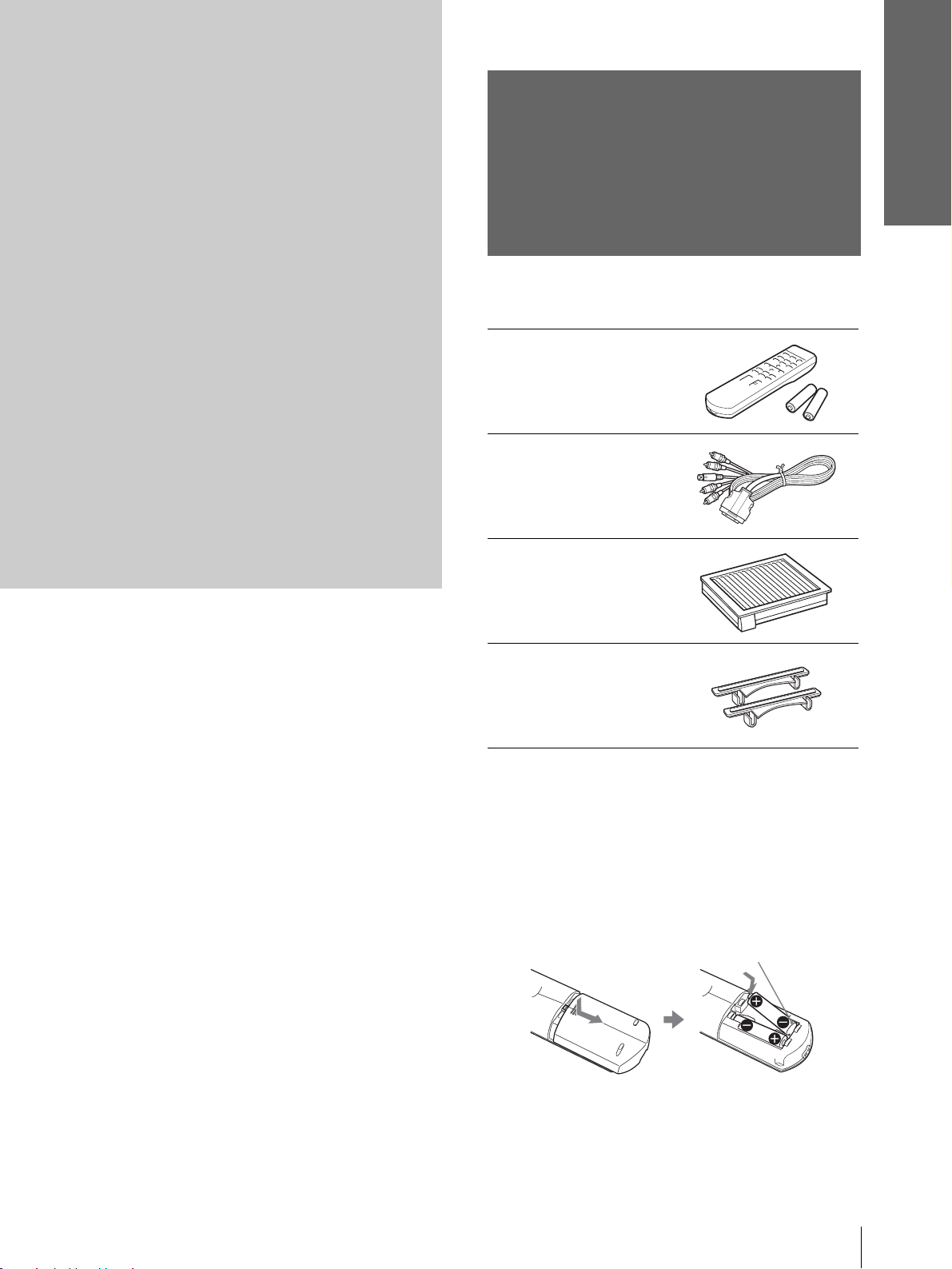
Unpacking
Check the carton to make sure it contains the
following items:
Remote control (1),
Size AA (R6)
batteries (2)
Signal interface
cable (1)
Air filter (for
replacement) (1)
Adjuster spacers (2)
AC power cord (1)
Operating Instructions (this manual) (1)
Inserting the batteries into the remote
control
Insert the batteries E side first as s hown
in the illustration.
Inserting them forcibly or with the
polarities reversed may cause a short
circuit and may generate heat.
Unpacking
5
GB
Page 6
Connections and
Preparations
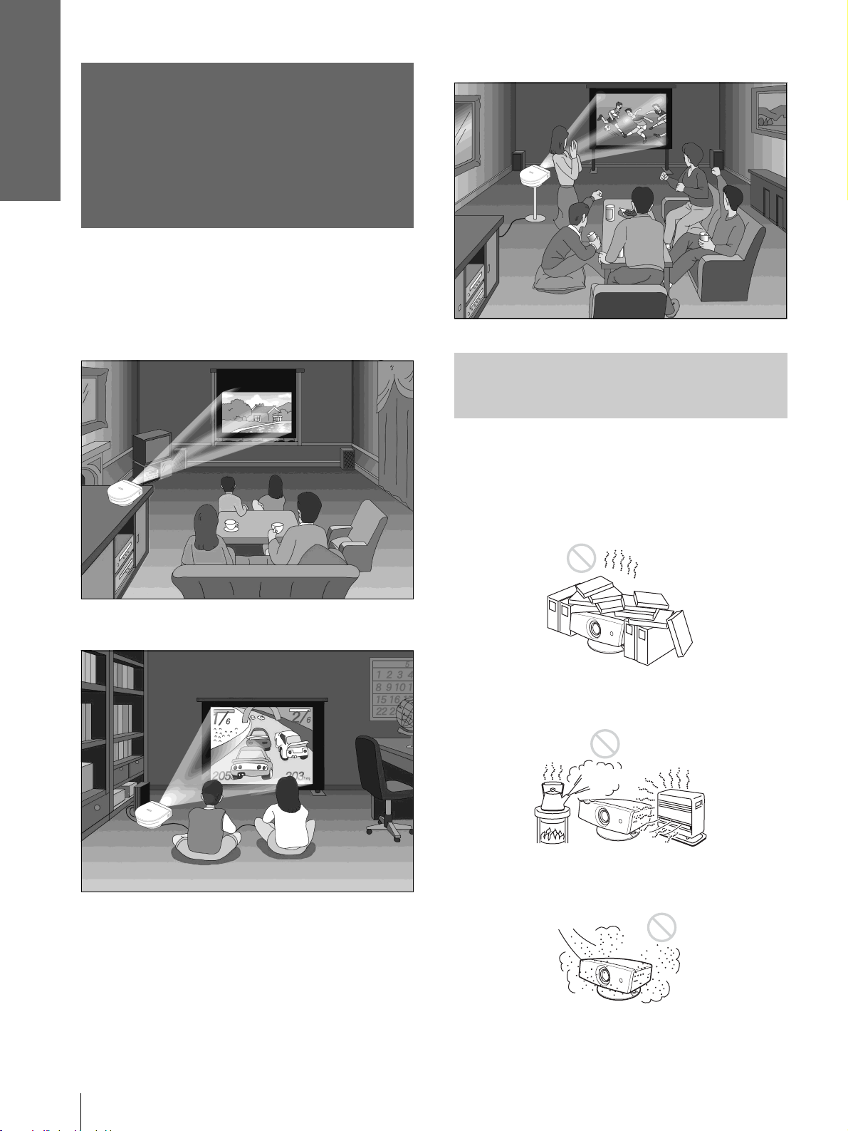
Watching sports, etc. with your company
Step 1: Installing
the Projector
You can obtain good picture quality even when you
project the picture from the side of the screen (“Side
Shot”) (1 page 8). You can enjoy home
entertainment with this projector in vari ous situations .
Enjoying home theater
Before Setting Up the
Projector
Enjoying video games on a large screen
Do not place the projecto r in the follo wing si tuations,
which may cause malfunction or damage to the
projector.
Poorly ventilated
Highly heated and humid
GB
Step 1: Installing the Projector
6
Very dusty and ext remely smoky
Page 7
Do not use the projector under the following
conditions:
Connections and
Preparations
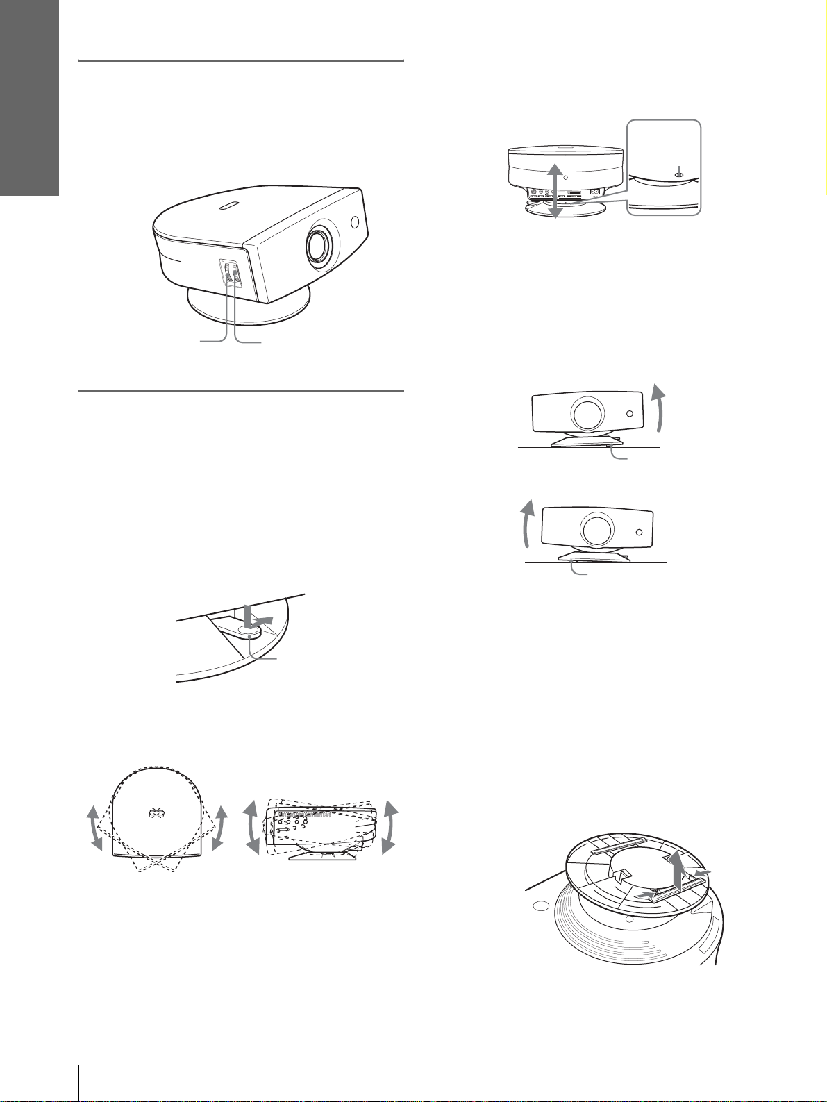
Installing the Pr ojector and
Tilting the unit extremely
Blocking the ventilation holes
Ventilation
holes
(exhaust)
Tip
For further details on the lo cat ion of th e ventilation holes (intake
or exhaust), see “Locatio n of Controls” on page 45.
Ventilation
holes
(intake)
Placing the projector withou t the adjuster
a Screen
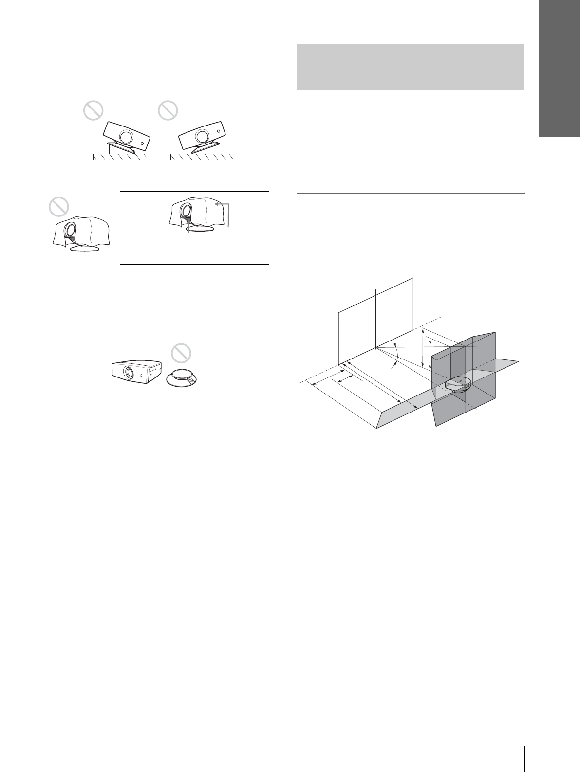
The installation dist ance between the projector and
screen varies depending on the size of the screen.
Note
When installing the pr ojec to r a n d scree n, b e sure not to tilt them.
If you tilt either or both of them, the adjustment cannot be
correctly carried out.
1
Determine the ins tallation
position of the projector and
screen.
Screen
f
8˚
e
Note
Installing the unit at altitudes
When using the projecto r at an al tit ude of 1,50 0 m or
higher, turn on high altitude mode in the INSTALL
SETTING menu. Failing to set thi s mode when us ing
the projector at high altitudes could have adverse
effects, such as reducing the reliability of certain
components.
d
c
5˚
b
a
Projector
a: Minimum projection distance between the
screen and the center of the projector’s lens
when you place the projector on the side
(“Side Shot”), or when you place the
projector with the center of the screen and the
center of the lens aligned.
b: Maximum projection distance between the
screen and the center of the projector’s lens
when you place the projector on the side, or
when you place the pr oje ct or with the center
of the screen and the center of the lens
aligned.
c: Maximum horizontal distance between the
right/left end of the screen and the center of
the projector’s lens when the projector is
placed on the side (when you use projection
distance a)
d: Maximum horizontal distance between the
right/left end of the screen and the center of
the lens when the projector is placed on the
side (when you use projection distance b)
Step 1: Installing the Projector
7
GB
Page 8
Connections and
Preparations
e: Maximum vertical distance from the bottom
of the screen to the center of the projector’s
lens when you place the pr ojector on the side
(when you use projection distance a)
f: Maximum vertical distance from the bottom
of the screen to the center of the projector’s
lens when you place the pr ojector on the side
(when you use projection distance b)
When projecting using “Side Shot”
adjustment only (1 page 17)
Position t he projector with the lens end within
the area in the illust ration, by using the
values a, b, c and d in the table belo w as a guide.
Unit: m (feet)
Screen
size
(inches)
a
b
c
d
Tip
The table shows the distances when proj ecting the video
signals. Dis tance s used for pr oject ing a 1080i/7 20p f ormat
signal and computer’s signal are shown on page 40 .
40 60 80 100 120 150
1.1
(3.6)
1.2
(3.9)
-0.2
(-0.7)
(0)0(0)0(0)0(0)0(0)0(0)
1.7
(5.6)
1.8
(5.9)
-0.2
(-0.7)
0
2.2
(7.2)
2.4
(7.9)3(9.8)
-0.3
(-1)
2.8
(9.2)
-0.4
(-1.3)
3.3
(10.8)
3.6
(11.8)
-0.4
(-1.3)
4.2
(13.8)
4.5
(14.8)
-0.4
(-1.3)
Screen
size
(inches)
d
e
f
Tip
The table shows the distances when projecting the
conventional video signals. Distances used for projecting a
1080i/720p format signal and computer’s signal are shown
on page 40 .
40 60 80 100 120 150
-0.1
(-0.3)
(0.3)
(0.7)
0.1
0.2
-0.1
(-0.3)
0.2
(0.7)
0.3
(1)
-0.1
(-0.3)
0.3
(1)
0.4
(1.3)
-0.1
(-0.3)
0.4
(1.3)
0.5
(1.6)
-0.2
(-0.7)
0.5
(1.6)
0.6
(2)
When projecting from th e center (1
page 19)
You can change the projection angle using the
adjuster. (1 page 16)
Position the projector with the lens en d within
the area in the illustration, by using the
values a and b in the table below as a guide.
Unit: m (feet)
Screen
size
(inches)
a
b
40 60 80 100 120 150
1
(3.2)
1.2
(3.9)
1.5
(4.9)2(6.5)
1.8
(5.9)
2.4
(7.9)3(9.9)
2.5
(8.2)3(9.9)
3.6
(11.9)
-0.3
(-1)
0.6
(2)
0.7
(2.3)
3.8
(12.4)
4.5
(14.9)
Note
If you project the pi cture using “Side Shot” only, set “V
Keystone” in the INSTALL SETTING menu to “Manu al,”
and adjust the level to “0.”
When projecting using both “Side Shot”
and “V Keystone” a djustments (1 page
18)
Position t he projector with the lens end within
the area in the illust ration, by using the
values a to f in the table below as a guide.
Unit: m (feet)
Screen
size
(inches)
a
b
c
40 60 80 100 120 150
1.2
(3.9)
1.3
(4.3)
-0.2
(-0.7)
1.7
(5.6)
1.9
(6.2)
–0.3
(–1)
2.2
(7.2)
2.5
(8.2)
–0.4
(–1.3)
2.8
(9.2)
3.1
(10.2)
–0.6
(–2)
3.4
(11.2)
3.7
(12.1)
–0.7
(–2.3)
4.2
(13.8)
4.6
(15.1)
–0.9
(–3)
For “Floor installation example”, see page 41.
2
Project an image on the screen
and adjust the picture so that it
fits the screen. (1 page 15)
T o project an image, connec t video equipment to
the projector. (1 page 9)
Note
When using a screen with an uneven surface, stripes pattern
may sometimes appear on the screen depending on the
distance between the screen and the projector or the
zooming magnifications. This is not a malfunction of the
projector.
GB
Step 1: Installing the Projector
8
Page 9

Step 2:
Connecting the
Projector
When making connections, be sure to do the
following:
• Turn off all equipment before making any
connections.
• Use the proper cables for each connection.
• Insert the cable plugs properly; plugs that are not
fully inserted often generate noise. When pulling
out a cable, be sure to pull it out from th e plug , not
the cable itself.
• Refer to the operati ng instru ction s of the co nnected
equipment.
• When you connect your projector to PJ MULTI,
select the input signal with the “Input-A Signa l Sel. ”
setting in the SET SETTING menu. (1 page
31)
Connections and
Preparations
--------------------------------------------------------------------------
• HDMI, the HDMI logo and High-Definition Multimedia
Interface are trademarks or registered trademarks of HDMI
Licensing LLC.
Step 2: Connecting the Projector
9
GB
Page 10
Connections and
Preparations
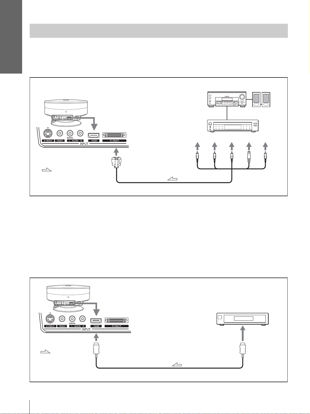
Connecting to a DVD Play er/Digital Tuner
To connect to a DVD player/digital tuner equipped with component video
connectors
You can connect a D VD player /digita l tuner equi pped with c omponent vide o connecto rs using t he suppli ed signal
interface cable.
R
Active
speakers
S
Video
Video
AV amplifier
Rear of the projector
DVD player, digital tuner, etc.,
with component video
connectors
Y
with SONY logo upside
: Video signal flow
Signal interface cable (SIC-HS40, supplied)
Tips
• To connect the projector to a DVD player/digital tuner which is not equipped with component video connectors, use the S video cable of
the DVD player/dig ita l tun er.
• To connect t he projector to a DVD player/digital tuner which is not equi pped with S video output, use the vid eo cable instead of the S
video cable.
• To connect the projector to a DVD player/digital tuner equipped with a D connector, use a commercially available conversion cable.
PB/
C
PR/
C
B
GB
To connect to a DVD player/digital tuner equipped with HDMI output
You can enjoy better picture b y connec ti ng a D VD play er/di gital tuner equ ipped wit h HDMI output to the HDMI
input of the projector.
Rear of th e projector
DVD player, digital
tuner, etc., with the
HDMI output
to HDMI output
: Video signal
flow
HDMI cable (not supplied)
10
Step 2: Connecting the Projector
Page 11
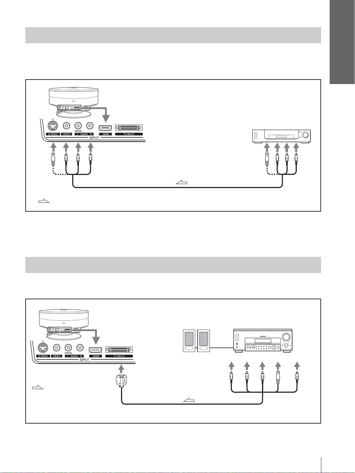
Connecting to Video Equipment
To connect to video equipment equipped with S video or video output
You can connect a VCR, Sony hard disk video recorder “Clip on” or a laser disk player. See also the instruction
manual for each equipment.
Rear of the projector
Video equipment
to S video or video/
audio output
Connections and
Preparations
S video or video/audio cable
: Video/audio signal flow
Tip
If you do not know to which connector you should connect the cable, S VIDEO (S video connector) or VIDEO (video connector), connect
it to S VIDEO (S video connector) to enjoy better picture quality.
If the equipment to be connecte d has no S VIDEO (S video connector), connect the cable to VIDEO (video con nector).
(VMC-810S, not supplied)
Connecting to an AV Amplifier
You can enjoy better sound quality by connecting the projector to an AV amplifier using the supplied signal
interface cable.
Rear of th e projector
Active speakers
AV amplifier
: Video signal flow
with SONY logo upside
Signal interface cable (supplied)
Y
Step 2: Connecting the Projector
PB/
C
PR/
S
C
R
B
Video
Video
11
GB
Page 12
Connections and
Preparations
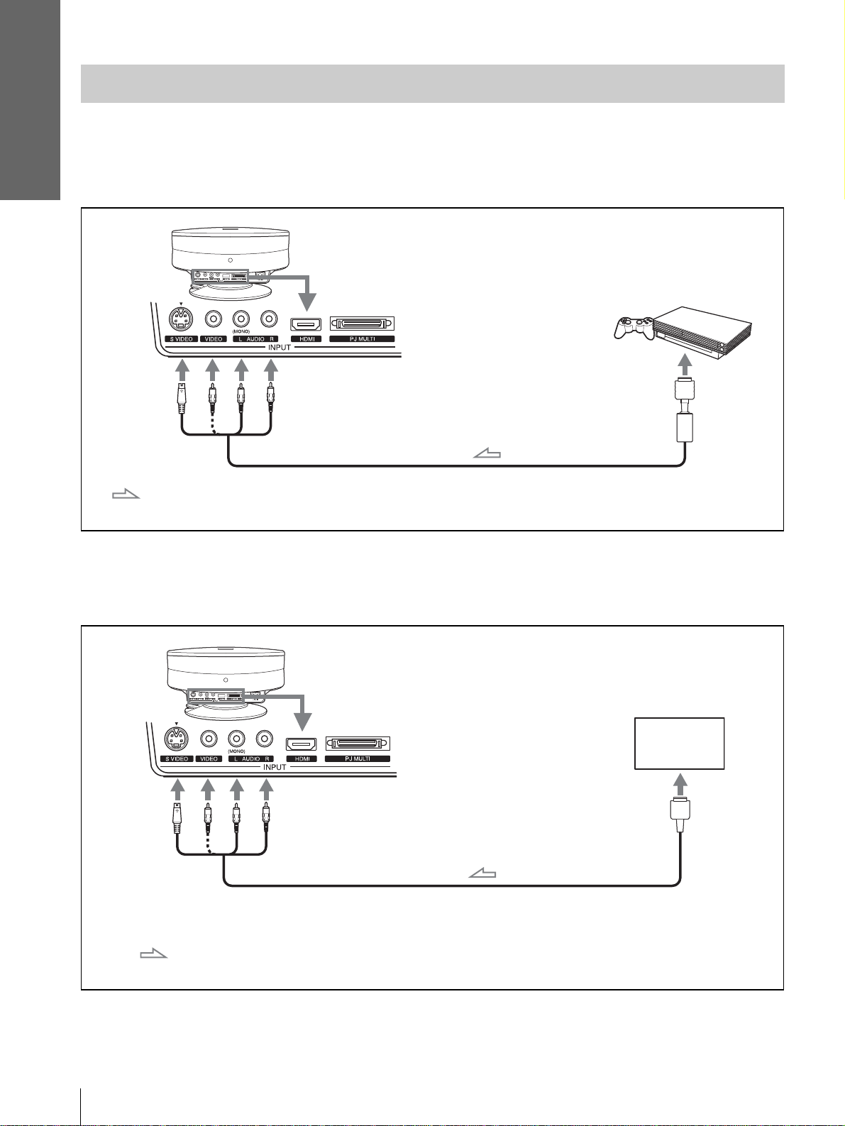
Connecting to “PlayStation 2,” etc.
To connect to the AV multi output of “PlayStation 2,” etc.
You can enjoy video games projected on the screen by connecting the projector to the “PlayStation 2,”
“PlayStation” (PS one) or “PlayStation.”
See also the instruction manual of the connected “PlayStation 2,” etc.
Rear of the projector
PlayStation 2
to A V multi output
AV cable (SCPH-10060 or SCPH-10030, not supplied)
: Video/audio signal
flow
To connect to another video game equipment
To connect to another video game equipment, refer to the instruction manual of the video game equipment.
Rear of the projector
Video game
to AV multi output
GB
12
Cable supplied with the video game equipment, or optional
cable which is compatible with the video game equipment
: Video/ audio signal
flow
Step 2: Connecting the Projector
Page 13
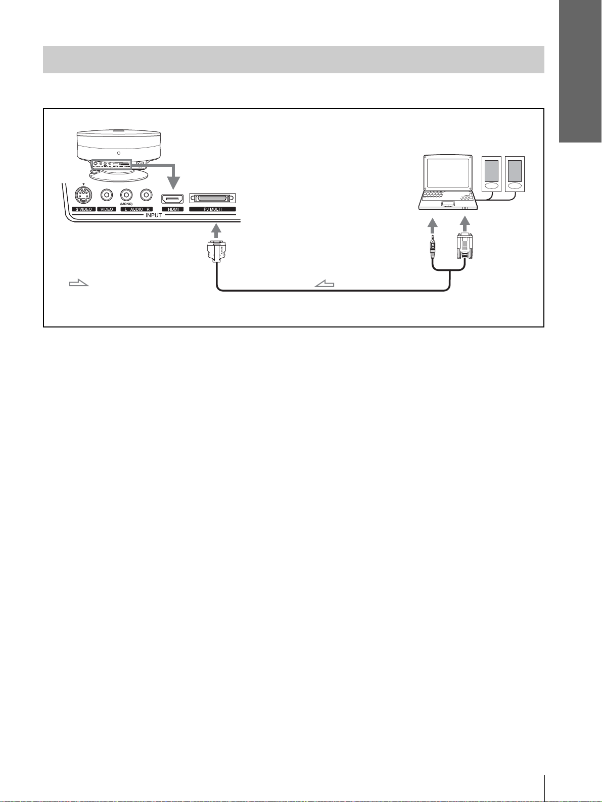
Connecting to a Computer
You can project a computer’s picture on a large screen using the optional signal interface cable (SIC-HS30).
Connections and
Preparations
Rear of the projector
: Video/audio signal
flow
with SONY logo upside
Signal interface cable (SIC-HS30, not supplied)
Computer
Active
speakers
to monitor
output
Step 2: Connecting the Projector
13
GB
Page 14
Connections and
Preparations
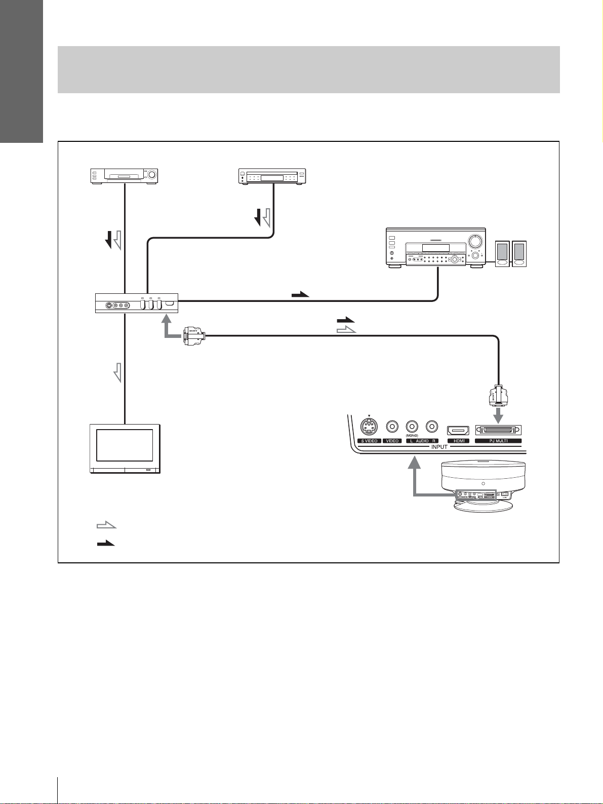
Connecting to V avious Equipment using the Optional Interface
Unit
You can connect other equipment using the optional interface unit. Additionally, you can select output to the
projector or the TV by switching the selector of the interface unit.
VCR, etc.
DVD player, etc.
Interface unit
(IFU-HS1, not supplied)
with SONY
logo upside
Audio amplifier
PJ muti cable (supplied to IFU-HS1)
with SONY logo upside
Active
speakers
TV
: Video signal flow
: Audio signal flow
Rear of the
projector
GB
14
Step 2: Connecting the Projector
Page 15
Step 3: Adjusting
the Picture Size
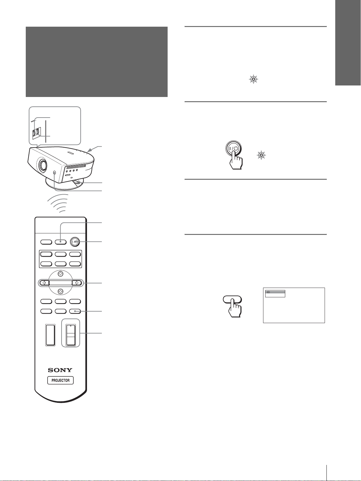
1
Plug the AC power cord into a
wall outlet.
The ON/STANDBY indicator lights in red and
the projector goes into standby mode.
Connections and
Preparations
and Position
5,7
5,8
Rear remote control
detector
Ajuster lock lever
Front remote control
detector
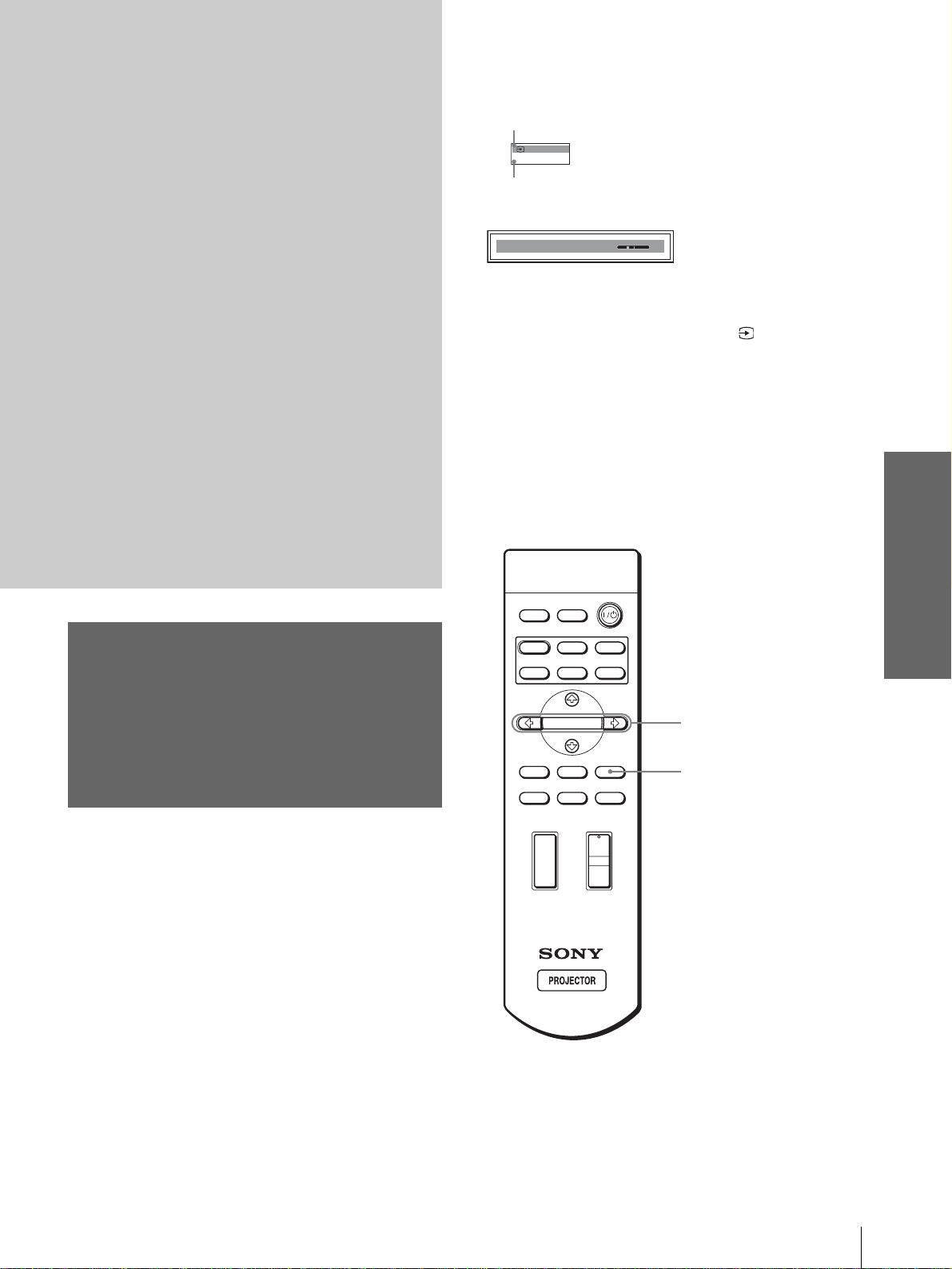
4
INPUTLIGHT
2
STANDARD
USER 2
ENTER
DDE
MUTING
CINEMA
+
–
USER 3USER 1
MENUAPA
RESET
M/m/</,/
ENTER buttons
RESET button
7
DYNAMIC
PICTURE MODE
WIDE MODE
VOLUME SIDE SHOT
+
–
ON/
STANDBY
2
Press the [/1 (on/standby)
Lights in red.
switch to turn on the projector.
The ON/STANDBY indicator lights in green.
ON/
Lights in green.
STANDBY
3
Turn on the equipment
connected to the projector.
Refer to the operating instructions of the
connected equipment.
4
Press INPUT to project the
picture on the screen.
Each time you press the button, the input
indication changes. (1 page 23)
Video 1
INPUT
NTSC 3.58
Tip
The ? /
1 (on/standby), INPUT, MENU, and M/m/</,/
ENTER (joystick) buttons on the side panel of the projector have
the same functions as those on the remote control.
Step 3: Adjusting the Picture Size and Position
15
GB
Page 16
Connections and
Preparations
5
Adjust the focus using the
FOCUS ring, and adjust the
picture size using the ZOOM
ring.
ZOOM ring
6
Adjust the position of the
FOCUS ring
picture to fit the screen using
the adjuster.
until the adjuster clicks into
lower side at the rear of the projector with a click.
the round hole in the
Round
hole
Adjusting the picture position using
the supplied adjuster spacer
Attaching one of the supplied spacers for adjuster
adjustment (spacers for 1
the projector to the right or left at a tilting angle up to
2
º.
º and 2°) allows you to tilt
Adjuster spacer
(supplied)
Adjusting the picture position using
the adjuster
Hold down and slide the adjuster lock lever to the
right, move the p rojector, then return the lock lever.
Adjuster lock lever
You can move the pro jecto r hori zontal ly or vertically
within the following ranges:
Up to 30° each
way horizontally
Up to 10° each way
vertically
Adjuster spacer (supplied)
To attach the supplied adjuster
spacer
1 Place a thick cloth (e.g., a cushion)
beneath the projector. Place the projector
face down.
2 While pressing the lock knobs inward,
remove the adjuster bar at the bottom of
the adjuster table to which y o u want to
attach the supplied spacer.
GB
To reset the projector to the center position
of the adjuster
Hold down and slide the adjuster lock lever to the
right, move the p rojector, then return the lock lever
16
Step 3: Adjusting the Picture Size and Position
3 Fit the spacer into the removed adjuster
bar spot.
Page 17
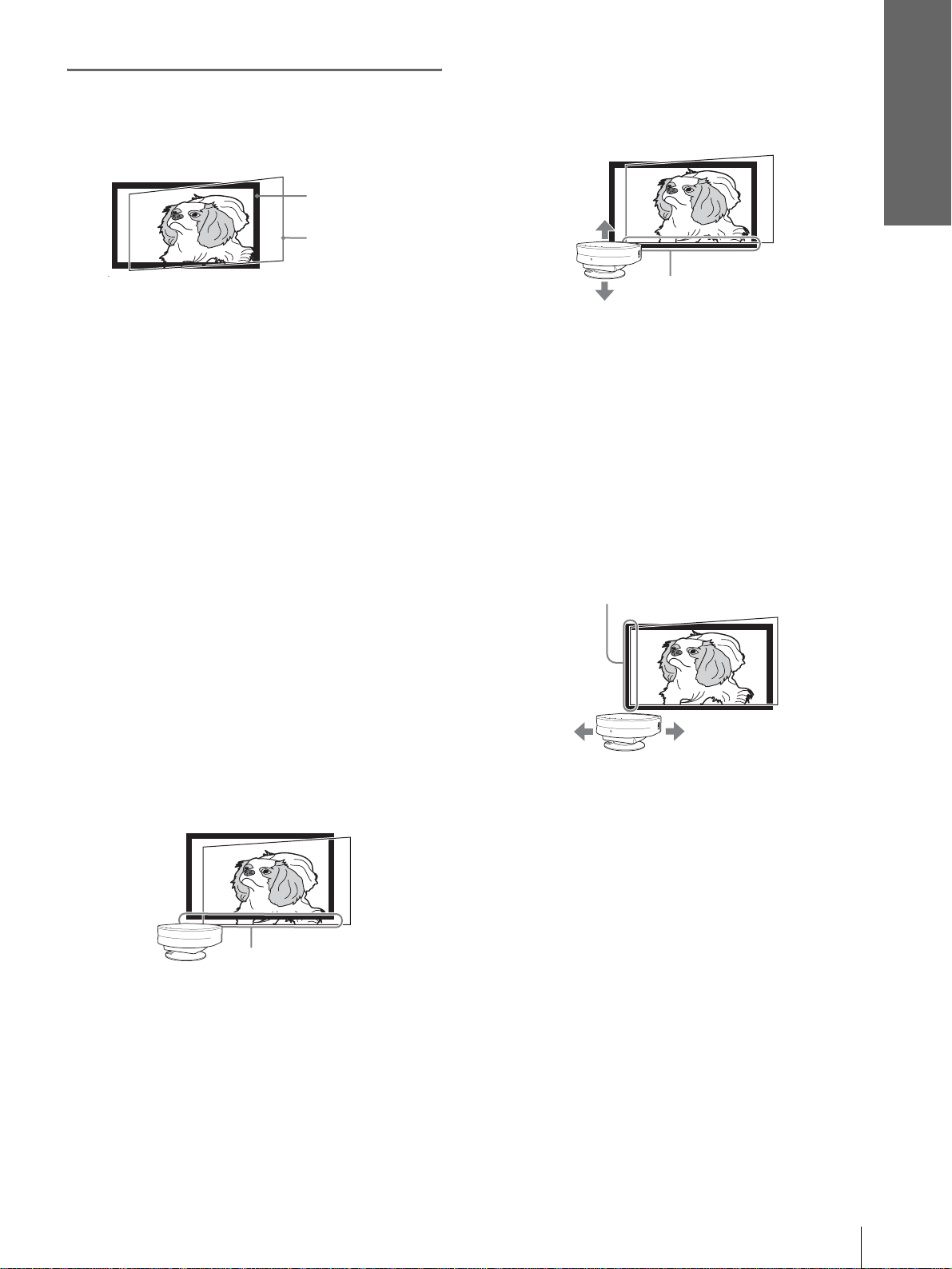
7
Adjust the picture size and
position.
Screen
Projected picture
If “Side Shot” or “V Keystone” are adjusted
manually (value adjustment), the built-in te st
pattern is pro jected on the screen. If you wa nt to
make adjustments usi ng the current input signal,
set “Test Pattern” in the INSTALL SETTING
menu to “Off.” (1 page 32)
When projecting using “Side Shot”
adjustment only
When projecting using “Side Shot” adjustment only,
you can adjust to correct horizontal trapezoidal
distortion using the “Side Shot” function to the
maximum.
1 Set “V Keystone” in the INST ALL SETTING
menu to “Manual", press ENTER and M, m
or RESET to set the level to “0”, then reset
the position of the adjuster (1 page 16).
Connections and
Preparations
3 Move the projector vertically so that the
bottom side of the picture fits the bottom
inside of the screen frame.
Adjust so that the bottom side
of the picture fits the bottom
inside of the screen frame.
When adjusting the picture height, do not use the
adjuster (1 page 16), but move the projector or
the screen vertically to adjust so that the bottom
side of the picture fits the bottom inside of the
screen frame.
4 Move the projector horizontally to t he left
or right so that one side of the pi cture fits
the inside end of the screen frame.
Adjust so that one side of the picture fits the
inside end of the screen frame.
Note
If “V Keystone” is set to “Auto, ” the correctio n capaci ty of “Side
Shot” is reduced.
2 Position the projector so that the picture
overlaps on the screen as shown below.
Adjust so that the bottom side
of the picture is parallel to the
bottom side of the screen.
Check that the vertical sides of the picture are
parallel to the vertical sides of the screen.
If the picture does not overlap on the screen as
shown above, confirm and adjust the installation
position of the projector and screen referring to
“Installin g the Projector and a Screen” (1 page
7).
If you position the proj ector on the le ft side of the
screen, adjust so th at the left si de of the pictur e fits
the left inside end of the screen frame. With the
projector positioned on the right side, adjust so
that the right side o f the picture f its the right inside
end of the screen frame.
Note
When adjusting so that one side of the picture fits the inside end
of the screen frame, make sure not to separate the bott om side of
the picture from the bottom inside of the screen frame.
Step 3: Adjusting the Picture Size and Position
17
GB
Page 18
Connections and
Preparations
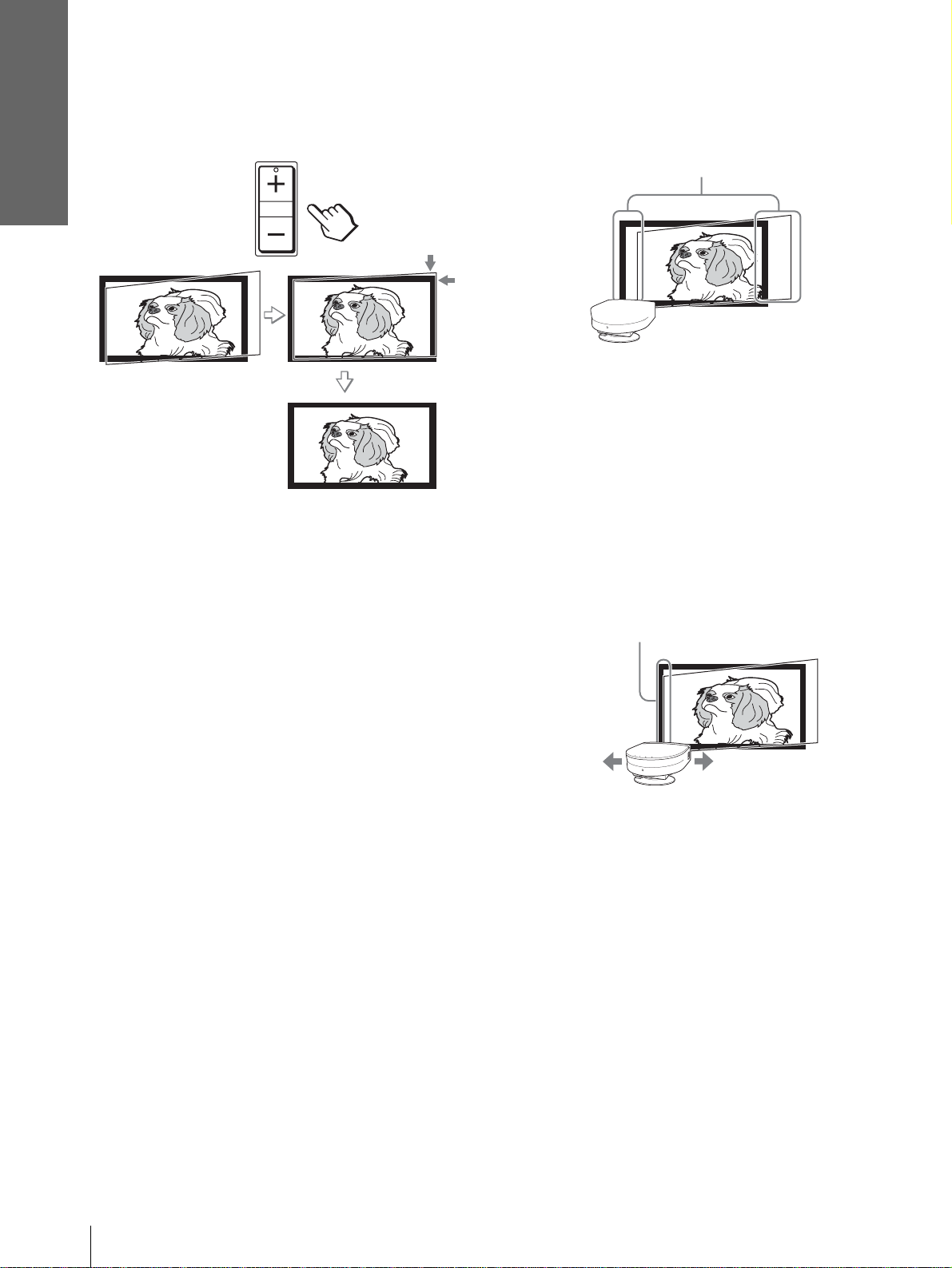
5 Adjust to correct horizontal trapezoidal
distortion using SIDE SHOT + or – .
SIDE SHOT
Press SIDE SHO T + or – so that the upper side of
the picture becomes pa rallel to the bottom side. If
the right side is longer than the left side, press
SIDE SHOT +. If the left side is longer than the
right side, press SIDE SHOT –. To fine-adjust the
distortion, press M or m.
2 Position the projector so that the pi cture
overlaps on the screen as shown below.
Adjust so that the vertical sides of t he pictu re ar e
paralle l to the vertical sides of the screen.
Check that both vertical sides of the picture are
parallel to the vertical sides of the screen.
If they are not parallel, set “V Keystone” in the
INSTALL SETTING menu to “Manual,” then
press ENTER and adjust the distortion with M or
m so that they become parallel.
3 Move the projector horizontally to the left
or right so that one side of the pi cture fits
the inside end of the screen frame.
Adjust so that one side of the picture fits the
inside end of the screen frame.
Note
Even when projecting using “Side Shot,” four sides of a picture
may sometimes not be parallel to the sides of a screen frame.
When projecting using both “Side
Shot” (1 page 32) and “V Keystone”
(1 page 32) adjustments
When projecting using both “Side Shot” and “V
Keystone” adjustments, vertical and horizontal
distortions are corrected.
1 Set the “V Keystone” in the INSTALL
SETTING menu to “Auto."
Note
“V Keystone” in the INSTALL SETTING menu is set to
“Manual” in the default. If it is set to “ Auto, ” the vertical d istortion
of the picture will be automatically corrected. The “V Keystone”
adjustment may not corre ct trapezoidal distortion perfectly,
depending on the room temperat ure or the screen ang le. In this
case, set manually by value adjustment.
If you position the proj ector on the lef t side of the
screen, adjust so th at the left si de of the pictur e fits
the left inside end of the screen frame. With the
projector positioned on the right side, adjust so
that the right side of the picture f its the right ins ide
end of the screen frame.
If the picture does not overlap on the screen,
determine and adjust the installation position of
the projector an d screen referr ing to “Install ing the
Projector and a Screen” (1 page 7).
GB
18
Step 3: Adjusting the Picture Size and Position
Page 19
Connections and
Preparations
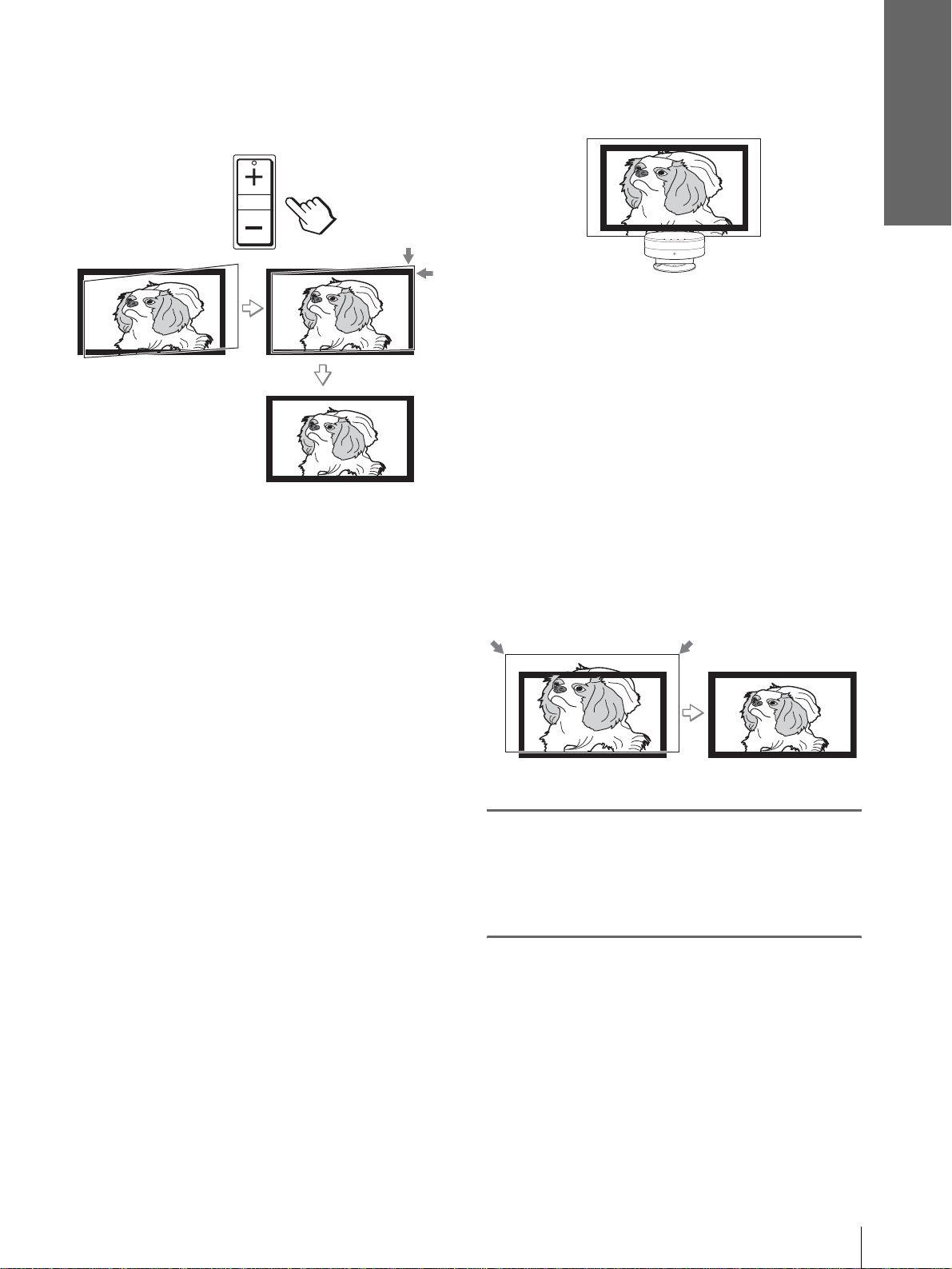
4 Adjust to correct horizontal trapezoidal
distortion using SIDE SHOT + or –.
SIDE SHOT
Press SIDE SHO T + or – so that the upper side of
the picture becomes parallel to the bottom side. If
the right side is longer than the left side, press
SIDE SHOT +. If the left side is longer than the
right side, press SI DE SHOT –. T o fine-adjust the
distortion, press M or m.
are parallel to the vertical frame ends of
the screen, as shown below.
If the picture does not overlaps on the screen as
shown above, confirm and adjust the installation
position of the projector and screen referring to
“Installing the Projector and a Screen” (1 page
7).
If the left and right sides of the picture are not
parallel to the left and right sides of the screen, set
“V Keystone ” in the INST ALL SETTING menu to
“Manual,” press ENTER, then adjust with M or m
so that they become parallel.
3 Adjust so that both ends of the bottom
side of the picture fit those of the bottom
side of the screen using the adjuster and
the ZOOM ring.
Note
Even when projecting using “Side Shot,” four sides of a picture
may sometimes not be parallel to the sides of a screen frame.
When projecting from the center
1 Set the “V Keystone” in the INSTALL
SETTING menu to “Auto."
Note
“V Keystone” in the INSTALL SETTING menu is set to
“Manual” in the default . If it is set to “ Auto, ” the v ertical distortion
of the picture will be auto m at icall y c o rrecte d . T he “ V Keystone”
adjustment may not correct trap ezoidal distortion perfectly,
depending on the r oom temperature or the screen angle. In this
case, set manually by value adjustment.
2 Position the projector so that the upper
and bottom sides of the picture are paralle l
to the horizontal frame ends of the screen,
and the left and right sides of the picture
8
Turn the FOCUS ring to adjust
the focus again.
Step 3: Adjusting the Picture Size and Position
19
GB
Page 20

Connections and
Preparations
1
Step 4:
Selecting the
Plug the AC po wer cord into a
wall outlet.
The ON/STANDBY indicator lights in red and
the projector goes into standby mode.
Menu Language
You can select one of thirteen languages for
displaying the menu and other on-screen displays.
The factory default setting is English.
INPUTLIGHT
STANDARD
DYNAMIC
PICTURE MODE
USER 2
ENTER
DDE
MUTING
WIDE MODE
VOLUME SIDE SHOT
+
+
CINEMA
USER 3USER 1
MENUAPA
RESET
2
4-6
3
ON/
STANDBY
2
Press the [/1 (on/standby)
Lights in red.
switch to turn on the pr ojector.
The ON/STANDBY indicator lights in green.
ON/
Lights in green.
STANDBY
3
Press MENU.
The menu appears.
The menu presently se lected is shown as a
yellow button.
PICTURE SETTING
Picture Mode:
Adjust Picture...
MENU
Volume: 30
Input A
–
Tip
You can operate the menu using the joystick on the side panel of
the projector instead of the M/m/</,/ENTER buttons on the
remote control.
–
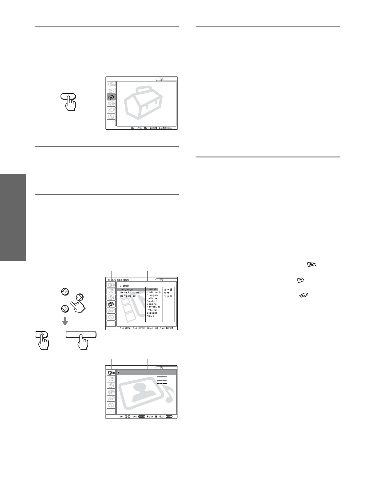
4
Press M or m to select the
MENU SETTING menu, and
press , or ENTER .
The select ed menu appears.
:
:
:
:
or
ENTER
Input A
A
GB
20
Step 4: Selecting the Menu Language
Page 21
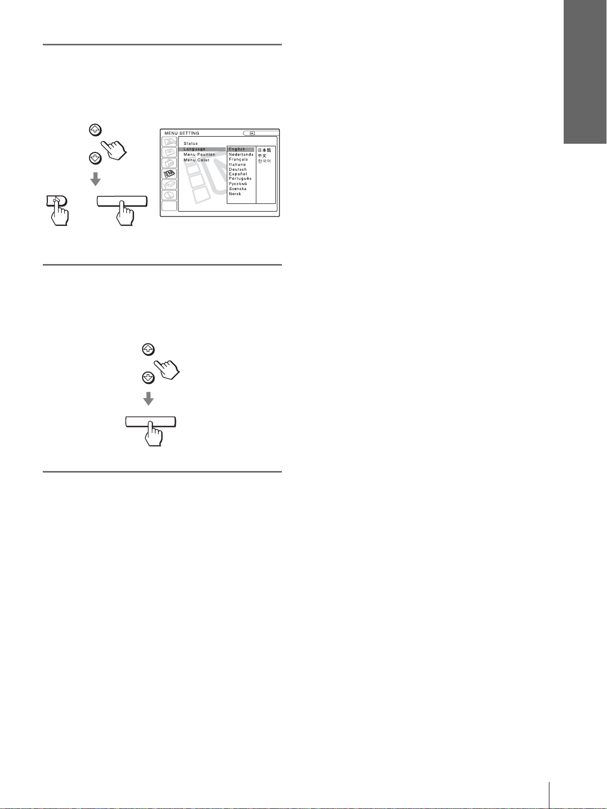
5
Press M or m to select
“Language”, and press , or
ENTER.
Connections and
Preparations
:
:
:
or
6
Press M or m to select a
ENTER
language, and press ENTER.
The menu changes to the selected language.
ENTER
Input A
:
To clear the menu
Press MENU.
Step 4: Selecting the Menu Language
21
GB
Page 22

Projecting
Projecting the
This section describes how to operate the
projector to view the picture from the
equipment connected to the projector. It
also describes how to select the wide
screen mode or the quality of the picture to
suit your taste.
Picture on the
Screen
4
INPUTLIGHT
2
STANDARD
USER 2
ENTER
DDE
MUTING
CINEMA
+
USER 3USER 1
MENUAPA
RESET
MUTING button
DYNAMIC
PICTURE MODE
WIDE MODE
VOLUME SIDE SHOT
+
–
–
7
1
Plug the AC po wer cord into a
wall outlet.
The ON/STANDBY indicator lights in red and
the projector goes into standby mode.
ON/
Lights in red.
STANDBY
GB
22
Projecting the Picture on the Screen
Page 23
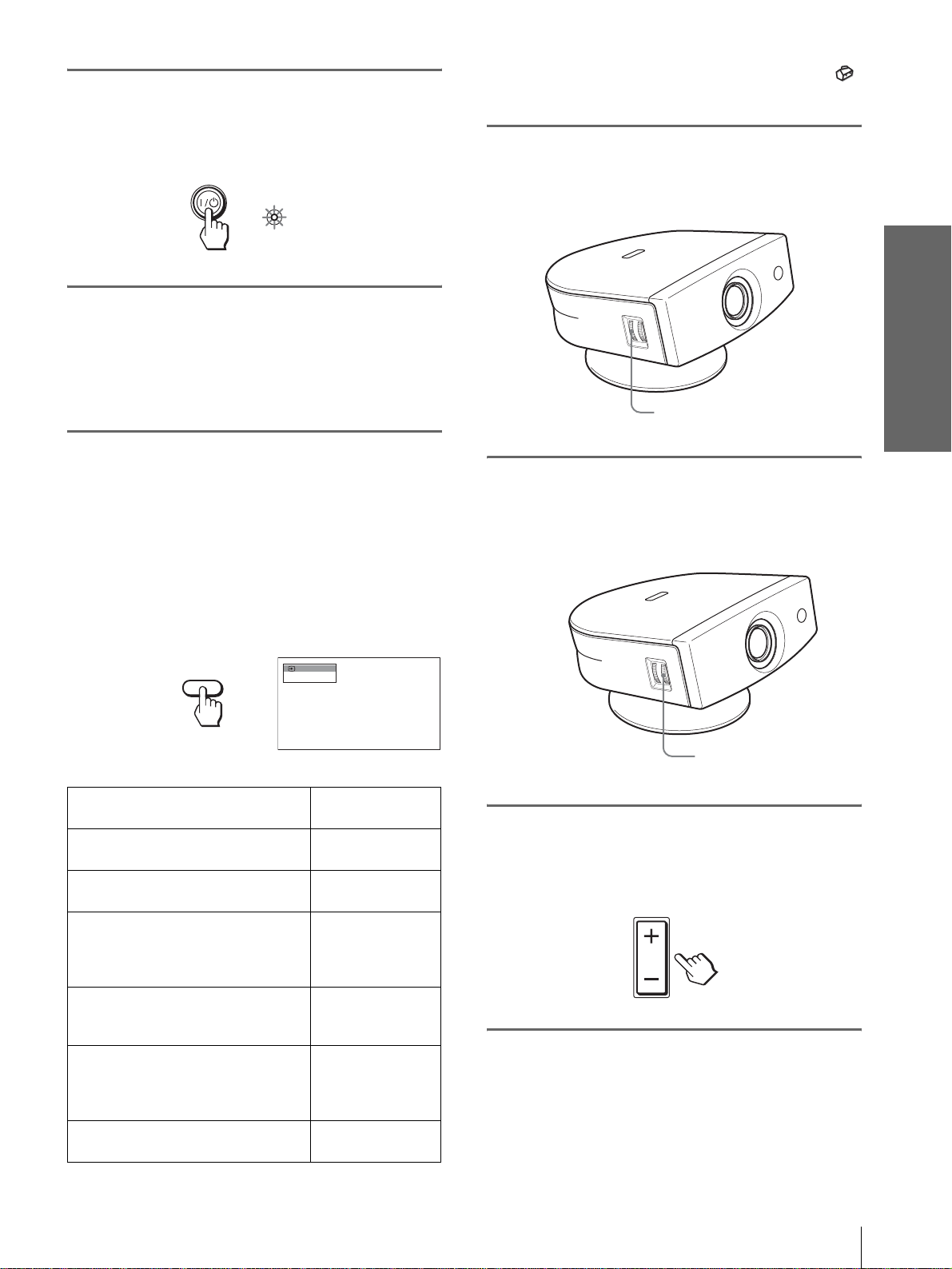
2
Press the [/1 (on/standby)
switch to turn on the projector.
The ON/STANDBY indicator lights in green.
ON/
STANDBY
3
Turn on the equipment
Lights in green.
connected to the projector.
Refer to the operating instructions of the
connected equipment.
4
Press INPUT repeatedly to
select the input you want to
project on the screen.
Display the indication of the input you want.
*
Set the “Input-A Signal Sel.” setting in the SET SETTING
menu according to the input signal . (1 page 31)
5
Turn the ZOOM ring to adjust
the size of the picture.
ZOOM ring
6
Turn the FOCUS ring to adjust
the focus.
Adjust to obtain sharp focus.
Projecting
Example:To view the picture from the video
equipment connected to the VIDEO
INPUT jack.
Video 1
INPUT
To view the picture from
Video equipment connected to
VIDEO INPUT on the projector
Video equipment connected to S
VIDEO INPUT on the projector
RGB/component equipment
connected to PJ MULTI INPUT via
the optional signal interface cable or
the interface unit
Video equipment connected to PJ
MUL TI INPUT via the optional signal
interface cable or the interface unit
Video equipment equipped with S
VIDEO connected to PJ MULTI
INPUT via the optional signal
interface cable or the interface unit
Equipment connected to HDMI
INPUT on the projector
NTSC 3.58
Press INPUT to
display
Video 1
S-Video 1
Input-A
Video 2
S-Video 2
HDMI
FOCUS ring
7
Press V OLUME + or – to adjust
the volume.
*
VOLUME
Projecting the Picture on the Screen
23
GB
Page 24

Cutting off the sound
Press MUTING on the remote
control.
To restore the sound, press MUTING again.
Selecting the
Wide Screen
Mode
Projecting
To turn off the power
1 Press the [/1 (on/standby) sw itch.
A message “POWER OFF?” appears on the
screen.
2 Press the [/1 switch again.
The ON/ST ANDBY indicator flashes in green and
the fan contin ues to run to r educe the int ernal heat.
Also, the ON/ST ANDBY indicator flashes quickly
during which you will not be able to light up the
ON/STANDBY indicator with the [/1 switch.
3 Unplug the AC power cord from the wall
outlet after the fan stops running and the
ON/STANDBY indicator lights in red.
You can turn off the proj ector by ho lding t he [/1 (on/
standby) switch for about one second, instead of
performing the above steps.
Y ou can en joy variou s wide screen mode according to
the video signal re ceived. You can also select it using
the menu. (1 page 30)
INPUTLIGHT
STANDARD
USER 2
ENTER
DDE
MUTING
CINEMA
+
–
USER 3USER 1
MENUAPA
RESET
WIDE MODE button
DYNAMIC
PICTURE MODE
WIDE MODE
VOLUME SIDE SHOT
+
–
GB
24
Press WIDE MODE.
Each time you press the button, you can select
the “Wide Mode” setting.
Selecting the Wide Screen Mode
Page 25
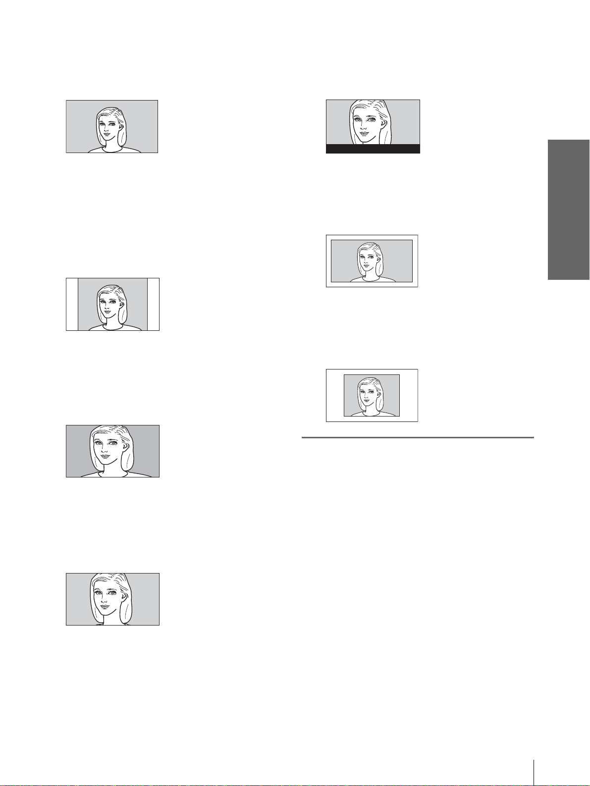
Full
A 16:9 squeezed picture is displayed with the
correct aspect ratio. A 4:3 picture is enlarged
horizontally to fit the 16:9 screen.
Subtitle
The subtitle area is compressed and displayed in
the lower part of the screen. Use this mode to
view a movie with subtitles.
Good-bye
Tip
Squeezed: An original 16:9 aspect ratio picture is recorded
horizontally compressed to a 4: 3 picture.
Normal
A picture with normal 4:3 aspect ratio is
displayed in the center of the screen to fil l the
vertical screen size.
Wide Zoom
A 4:3 aspect ratio picture is enlarged and the
upper and lower portions of the picture are
compressed to fit the 16:9 screen. Use this mode
to view news, variety shows, etc.
Zoom
A normal 4:3 aspect ratio picture is enlarged
vertically and horizontal ly in the same ra tio to
fill the 16:9 screen. This mode is ideal for
viewing a wide-format movie.
Full Through
One-to-one mapping is done on a squeeze d 16:9
picture. It is displayed in the center of the
screen.
Normal Through
One-to-one mapping is done on a 4:3 normal
aspect ratio picture. It is displayed in the center
of the screen.
Notes
• You can adjust the vertical position of the picture with “V
Position” in the INPUT SETTING menu when “Zoom” or
“Subtitle” is selected, or when “Full Through” or “Normal
Through” is selected f or video (50Hz) or progress ive
component (50p) input signal.
• You can adjust the position of the subtitle s with “T itle Area” in
the INPUT SETTING menu only when “Subtitle” is selected.
• If “Full Through” or “Normal Through” is selected when a
video (50 Hz) or progressive video (50p) signal is in put, the
picture may not be completely displayed on the screen due to
the number of dots of the LCD panel.
Projecting
Notes on selecting the wide screen mode
• Select the wide screen mode taking into account
that changing the aspect rati o of the ori ginal pict ure
will provide a different look from that of the
original image.
• Note that if the projector is used for profit or for
public viewing, modifying the original picture by
switching to the wide mode may constitute an
infringement of the rights of authors or producers,
which are legally protected.
Selecting the Wide Screen Mode
25
GB
Page 26
Projecting
Selecting the
Picture Viewing
Mode
You can select the picture viewing mode that best
suits the type of program or room condition.
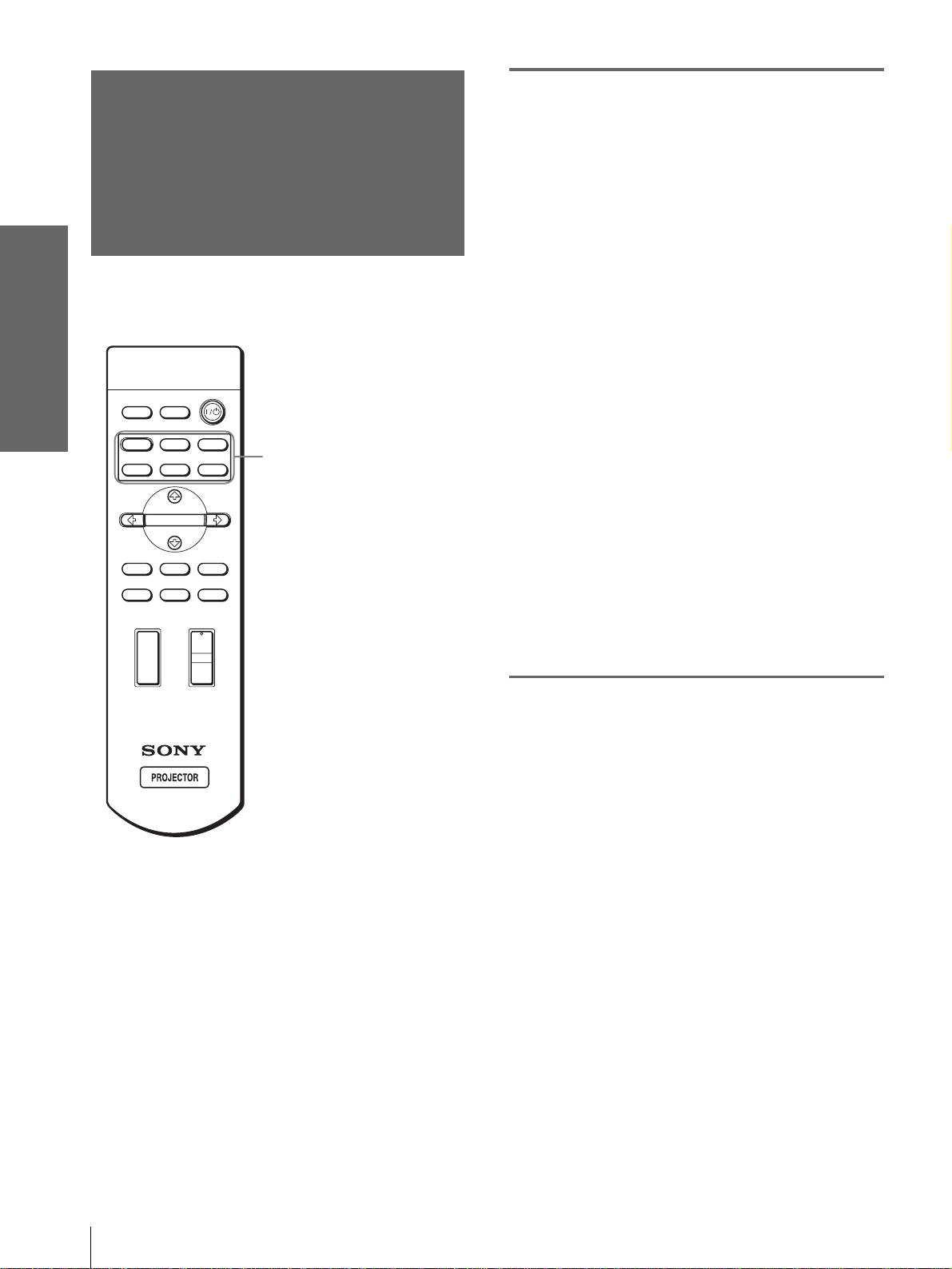
Press one of the PICTURE
MODE buttons (DYNAMIC,
STANDARD, CINEMA and
USER 1, 2 and 3).
DYNAMIC
Select for enhanced picture contrast and
sharpness.
STANDARD
Recommended for normal vie wi ng con dit ion in
your home.
Also select to reduce roughness when viewing
the picture with DYNAMIC.
INPUTLIGHT
STANDARD
DYNAMIC
PICTURE MODE
USER 2
ENTER
DDE
MUTING
WIDE MODE
VOLUME SIDE SHOT
+
–
+
–
CINEMA
USER 3USER 1
MENUAPA
RESET
PICTURE MODE buttons
DYNAMIC
STANDARD
CINEMA
USER 1, 2 and 3
CINEMA
Select for soft, film-like pictu re.
USER 1, 2 and 3
You can adjust the quality of the picture to suit
your taste and stor e the settings in to the selec ted
memory of the projecto r . Press one of the USER
1, 2 and 3 buttons, then adjust the picture by
using the menus. The settings are stored, and
you can view the picture with the adjusted
picture quality by pre ssing t he b utto n. (1 page
29)
GB
26
Selecting the Picture Viewing Mode
Page 27
Display items
Using the
Menus
This section describes how to make
various adjustments and settings using the
menus.
Input signal indicator
Video 1
NTSC 3.58
Input signal setting indicator
Picture adjustment menu
Contrast: Min
Input signal indicator
Shows the selected input channel. is displayed
when no signal is input. You can hide this indicator
using “Status” in the MENU SETTING menu.
Input signal setting indicator
For Input-A: Shows “Computer,” “Component” or
“Video GBR.”
For V ideo/S V ideo input: Sho ws “ Auto” or the “Color
System” setting in the SET SETTING menu.
x
Using the Menus
Operation
through the
Menus
The projector is equipped wi th an on-screen me nu for
making various adj ustment s and set ting s. The set ting
items are displayed in a pop-up menu or in a sub
menu. If you select an item name followed by dots
(...), a sub menu with setting items appear. You can
change the tone of the menu display and the menu
language displayed in the on-screen menu.
To change the menu language, see “Selecting the
Menu Language” on page 20.
INPUTLIGHT
STANDARD
DYNAMIC
PICTURE MODE
USER 2
ENTER
DDE
MUTING
WIDE MODE
VOLUME SIDE SHOT
+
–
+
–
CINEMA
USER 3USER 1
MENUAPA
RESET
2-4
1
Operation through the Menus
27
GB
Page 28
1
Press MENU.
The menu appears.
4
Make the setting or adjustment
on an item.
The menu presently selected is shown as a
yellow button.
MENU
SET SETTING
Smart APA: On
Auto Input Search:
Input-A Signal Sel.:
Color System: Auto
Power Saving: Off
Illumination: Off
Off
Computer
Input A
When changing the adjustment level
To increase the value, press M or ,.
T o decrease the value, press m or <.
Press ENTER to restore the original screen.
When changing the setting
Press M or m to change the setting.
Press ENTER to restore the original screen.
You can restore the original screen using <
depending on the selected item.
2
Press M or m to select a menu,
and press , or ENTER.
Using the Menus
The select ed menu appea rs.
To clear the menu
Press MENU.
To reset items that have been
3
Press M or m to select an item
you want to adjust and press
, or ENTER .
The setting items are displayed in a pop-up
menu or in a sub menu.
Pop-up menu
Menu Setting items
Input A
adjusted
Select the item you want to reset, then press RESET.
“Complete!” appears on the screen and the setting is
reset to its factory preset value.
Items that can be reset are:
• “Contrast,” “Brightness,” “Color,” “Hue,”
“Sharpness” and “RGB Enhancer” in “Adjust
Picture...” of the PICTURE SETTING menu
• “Dot Phase,” “H Size” and “Shift” in “Adjust
Signal...” of the INPUT SETTING menu
• “V Keystone” (when set to “Manual”) and “Side
Shot” of the INASTALL SETTING menu
GB
28
or
Operation through the Menus
ENTER
Sub menu
Menu Setting items
Graphics
High
Input A
PICTURE SETTING
ADJUST PICTURE
Contrast: 80
Brightness: 50
RGB Enhancer: 30
Gamma Mode:
Color Temp:
Standard
Page 29
Menu Lists
Menu Configurations
The projector is equipped with six pages. The items
that can be adjusted in each menu are described on
page 29 to 32.
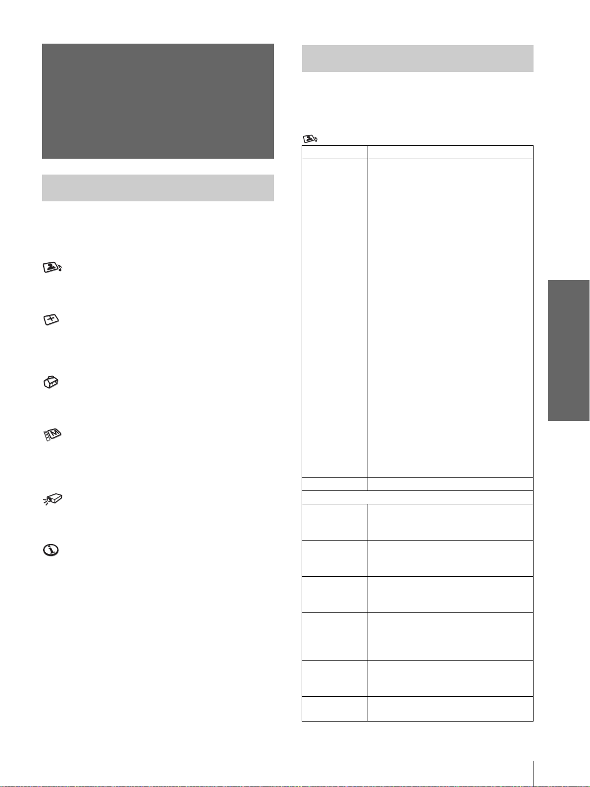
PICTURE SETTING menu
The PICTURE SETTING menu is used for adjusti ng
the picture. You can also adjust the volume.
INPUT SETTING menu
The INPUT SETTING menu is used to adju st the
input signal. You can adjust the size of the picture, and
select wide screen mode, etc.
SET SETTING menu
The SET SETTING menu is used for changing the
settings of the projector.
MENU SETTING menu
The MENU SETTING menu is used to change the onscreen language, disp lay position of the menu screen,
etc.
INSTALL SETTING menu
The INST ALL SETTI NG menu is used for cor recting
distortion of the picture.
INFORMATION menu
The INFORMATION menu is used to display the
horizontal and ve rtical freq uencies of the in put signal
and the used time of the lamp.
Menu Items
Adjustable items are limited according to the input
signals. Items that cannot be adjusted are not
displayed in the menu. (1 page 43)
PICTURE SETTING
Item Description
Picture Mode You can select picture viewing mode that
best suits the type of picture or the
environment.
Dynamic: Select for enhanced picture
contrast and sharpness.
Standard: Recommended for normal
viewing condition. Also select to reduce
roughness when viewing the picture
with Dynamic.
Cinema: Select for soft, film-like picture.
User 1, 2 and 3: You can adjust the
quality of the picture to suit your taste
and store the settings. Once the settings
are stored, you can view the picture with
the adjusted picture quality by pressing
the PICTURE MODE.
To store the settings
1 Select “User 1”, “User 2” or “User 3”.
2 Adjust the items you want in the
menus.
Items that can be stored are:
“Adjust Picture...” items other than
“Volume,” and “Wide Mode” setting
Tip
You can also adjust the picture quality
in “Dynamic”, “Standard” or “Cinema”
mode. To reset to the factory setting,
press RESET.
Volume Adjusts the volume.
Adjust Picture…
Contrast The higher the setting, the greater the
contrast. The lower the setting, the lower
the cotrast.
Brightness The higher the setting, the brighter the
picture. The lower the setting, the darker
the picture.
Color The higher the setting, the greater the
intensity. The lower the setting, the lower
the intensity.
Hue The higher the setting, the more greenish
the picture becomes. The lower the
setting, the more purplish the picture
becomes.
Sharpness The higher the setting, the sharper the
picture. The lower the setting, the softer
the picture.
RGB
Enhancer
Adjusts the picture sharpness when
computer signals are input.
Using the Menus
Menu Lists
29
GB
Page 30
Item Description
Black Level
Adj (Adjust)
Gamma Mode Graphics: Reproduce s t he photos in
Color Temp. High: Gives the white colors a blue tint.
DDE
(Dynamic
Detail
Enhancer)
Using the Menus
Cinema
Black Pro
Emphasizes black color to produce a
bolder “dynamic” picture. Set according
to the input signal source.
High: Gives higher emphasis to the black
color.
Low: Gives lower emphasis to the black
color.
Off: Cancels this feature.
natural tones.
Text: Contrasts black and white. Suitable
for images that contain lots of text.
Middle: Gives the white colors a neutral
tint.
Low: Gives the white colors a red tint.
Off: Plays a video signal in an interlace
format without converting.
Progressive: Converts an interlace format
video signal to a progressive format .
Film: Normally, select this option.
Reproduces the 2-3 Pull-Down film
sources with smoo th pic tu re mo v eme nt.
When the video signal with a format
other than the 2-3 Pull-Down is input,
“Progressive” is automatically selected.
Iris Control
Switches the iris function during
projection.
Off: Normal contrast.
On: Enhances the black by emphasizing
the contrast.
Lamp Control
Switches the lamp wattage during
projection.
High: Normal wattage.
Low: Enhances the black by reducing the
lamp wattage.
Tip
If “Lamp Control” is set to “Low,” the next time
the power is turned on, the lamp will use the
“High” setting initially, and then go to “Low."
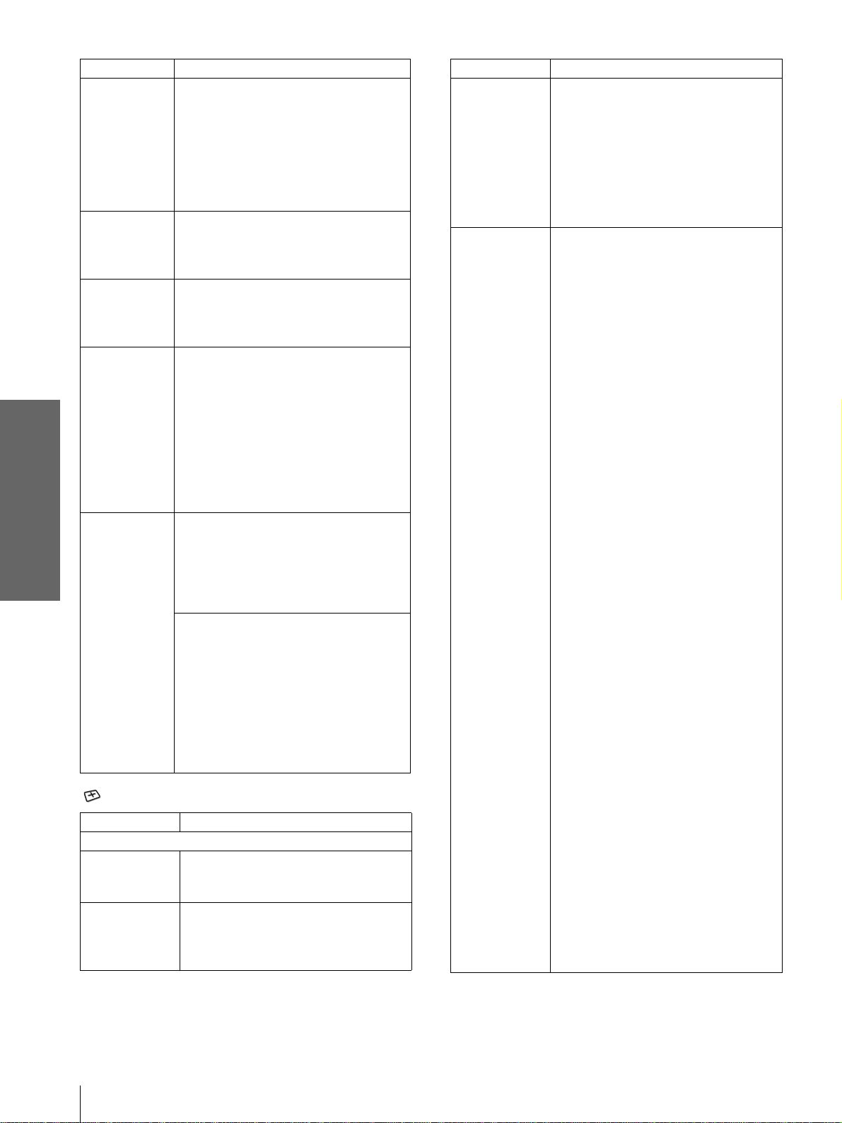
INPUT SETTING
Item Description
Adjust Signal…
Dot Phase Adjusts the picture from a computer for
clearer picture after it is adjusted by
pressing the APA button.
H Size Adjusts the horizontal size of the picture
from a computer. The higher the setting,
the wider the picture. The lower the
setting, the narrower the picture.
Item Description
Shift As the setting for H (horizontal)
increases, the picture moves to the right,
and as the setting decreases, the picture
moves to the left. Use < or , to adjust
the horizontal position.
As the setting for
the picture moves up, and as the setting
decreases, the picture moves down. Use
M or m to adjust the vertical position.
Wide Mode You can select the 4:3 aspect ratio picture
mode, “Normal” and “Normal Through,”
and 16:9 aspect ratio picture mode,
“Full,” “W ide Zoom, ” “Zoom, ” “Subtitle”
and “Full Through.”
Full: The 16:9 squeezed* picture is
diplayed with the correct aspect. The
4:3 picture is e nlarged horizontally to
fit the 16:9 screen.
* squeezed: An original 16:9 aspect
ratio picture is recorded horizontally
compressed to be a 4:3 picture.
Normal: The picture with normal 4:3
aspect ratio is displayed to fill the
vertical screen size.
Wide Zoom: The picture with 4:3 aspect
ratio is enlarged and the upper and
lower portions of the picture are
compressed to fit the 16:9 screen. Use
this mode to view news, variety shows,
etc.
Zoom: The normal 4:3 aspect ratio
picture is enlarged verticall and
horizontally at the equal ratio to fill the
16:9 screen. The mode is ideal for
viewing a wide-format movie.
Subtitle: The subtitle area is compressed
and displayed at the lower part of the
screen. Use this mode to view a movie
with the subtitle.
Full Through: One-to-one mapping is
done on a squeezed 16:9 picture. It is
displayed in the center of the screen.
Normal Through: One-to-one mapping
is done on the picture with 4:3 aspect
ratio. It is displayed in the center of the
screen.
Note
If “Full Through” or “ N ormal Through” is
selected when a video (50 Hz) or progressive
video (50p) signal is input, the picture may not
be completely displayed on the screen due to the
number of dots of the LCD panel.
For details, see “Selecting the Wide
Screen Mode” on page 24.
V (vertical) increases,
GB
30
Menu Lists
Page 31

Item Description
V Position Adjusts the vertical position of the picture
in wide screen mode. As the setting
increases, the picture moves up. As the
setting decreases, the picture moves
down.
Note
This item is adjustable only when “Zoom” or
“Subtitle” is selected, or when “Full Through”
or “Normal Through” is selected for video
(50Hz) or progressive component (50p) input
signal.
Title Area Adjusts the subtitle area. As the setting
increases, the subtitle area moves up. As
the setting decreases, the subtitle area
moves down.
Note
This item is adjustable only whe n “Subtitle” is
selected.
Note
For input signals from the HDMI connector, “Dot Phase,” “H
size” and “Shift” are not adjust able.
SET SETTING
Item Description
Smart APA With this item set to On, th e APA function
works automatically for a signal input from
a computer so that the picture can be seen
clearly. You can also activate the APA
function by pressing the AP A bu tton on the
remote control.
Tip
The APA (Auto Pixel Alignment) automatically
adjusts the input signal from a computer so that
the picture can be seen clearly.
Auto Input
Search
Input-A Signal
Sel.
Color System Select the color system of the input signal.
Set to On when an optional Interface Unit
such as the IFU-HS1 is connected to the PJ
MULTI connector on the projector.
Selects the signal input from the equipment
by selecting “Input-A” with the INPUT
button.
Computer: Inputs the signal from a
computer.
Component: Inputs the component or
progressive component signal from a
DVD player, digital tuner, etc.
Video GB R: Inputs the signal from a
digital tuner.
Auto: Selects the color system of the input
signal automatically from among NTSC,
PAL, SECAM, NTSC
4.43, PAL-M or
PAL-N.
“NTSC3. 58”–“PAL-N”: Sets the color
system to the selected system manually.
Item Description
Power Saving When set to On, the POWER SAVING
indicator lights. The projector goes into
power saving mode if no signal is input for
10 minutes, and the lamp goes out and the
cooling fan keeps running. In power saving
mode, no button functions for the first 60
seconds. It is cancelled when a signal is
input or any button is pressed. If you do not
set the projector to power saving mode,
select Off.
Illumination Turns on the illumination on the top panel
of the projector whe n set t o On. It turn s off
when set to Off.
MENU SETTING
Item Description
Status Set to Off to turn off the on-screen
displays except for the menus, mes sage
when turning off the power, and warning
messages.
Language Selects the la ng ua ge u se d i n the menu and
on-screen displays. Available languages
are: English, Dutch, French, Italian,
German, Spanish, Portuguese, Russian,
Swedish, Norweg ian, Japanese, Chinese,
and Korean.
Menu Position Selects the display position from Top
Left, Bottom Left, Center, Top Right
and Bottom Right.
Menu Color Selects the tone of the menu display from
White or Black.
Using the Menus
Menu Lists
31
GB
Page 32

INSTALL SETTING
Item Description
V Keystone
Side Shot
Using the Menus
Image Flip
Background
Test Pattern
High Altitude
Mode
Corrects the vertical trapezoidal distortion of
the picture. ( )
Auto: Normally set to this postion.
Manual: Sets a lower value (– direction)
when the bottom of the trapez oid is lo nger
than the top. Sets a higher value (+
direction) when the top of the trapezoid is
longer than the bottom. If you project the
picture using “Side Sho t” only, set to
“Manual,” and adjust the level to “0.”
Note
The “V Keystone” adjustment may not correct
the trapezoidal distortion perfectly, depending on
the room temperature or the scre en angle. In this
case, adjust the di stortion manually.
Corrects the horizontal trapezoidal distortion
of the picture. ( )
Set the level to “0” when you adjust the
picture using “V Keystone” only.
Note
Even when projecting using “Side Shot,” four
sides of a picture may sometimes n ot be pa rallel
to the sides of a screen frame.
Flips the picture on the screen horizontally
and/or vertically.
Off: The picture does not flip.
HV: Flips the picture horizon tally and
vertically.
H: Flips the picture horizontally.
V: Flips the picture vertically.
Selects the bac kground color of the scr e en
when no signal is input. You can sele ct
“Black” or “Blue.”
When set to On, a test patt ern is display ed on
the screen when adjusting using “Side Shot”
or “V Keystone.” If you do not want to
display a test pattern, set to Off.
Off: Use this setting when using the
projector at normal altitudes.
On: Use this setting when usin g the projector
at an altitude of 1,500 m or higher.
Note
When using the projector at high altitudes with
Off setting, the following message may appear.
“Probably use i n high altitude. Switch to high
altitude mode on ? YesR Nor
If you select “Yes,” “High Altitude Mode”
turns automatically to On.
About the Preset Memory
No.
This projector has 34 types of preset data for input
signals (the preset memory) . When the preset signal is
input, the projector automatically detects the signal
type and recalls the data for the signal from the preset
memory to adjust it to an optimum picture. The
memory number and signal type of that signal are
displayed in the INFORMATION menu.
INFORMATION
fH: 48.47kHz
fV: 60.00Hz
No.23
1024x768
Lamp Timer: 0H
Y ou can als o adjust the preset da ta through the INPUT
SETTING menu.
This projector also has 20 t ypes of user memori es for
Input-A into which you can save the setting of the
adjusted data for an unpreset input signal.
When an unpreset signal is input for the first time, a
memory number is displayed as 0. When you adjust
the data of the sign al in the INPUT SETTING menu,
it will be regist ered to the projector. If more than 20
user memories are registered, the newest memory
always overwrites the oldest one.
See the chart on page 44 to find if the signal is
registered to the preset memory.
Since the data is recalled from the preset memory
about the following signals, you can use these preset
data by adjusting “H size.” Make fine adjustment by
adjusting “Shift.”
Signal Memory No. H size
Super Mac-2 23 1312
SGI-1 23 1320
Macintosh 19” 25 1328
Input A
Memory No.
Signal type
GB
INFORMATION
Item Description
fH
fV
Lamp Timer
32
Menu Lists
Note
When the aspect ratio of input signal does not match the screen
size, a part of the scre en is disp la ye d in bla c k.
Displays the horizontal frequency of the input
signal.
Displays the vertical frequency of the input
signal.
Indicates how long the lamp has been turned
on.
Page 33

Adjusting Picture Quality of
a Signal from the Computer
You can automatically adjust to obtain the clearest
picture when projecting a signal from the computer.
1 Project a still picture from the computer.
2 Press the APA (Auto Pixel Alignment)
button.
When the picture is adj usted properly , “complete!”
appears on the screen.
Notes
• When “Smart APA” is set to “On,” the APA function is
automatically activated.
• Press the APA button when the image appears on the whole
display area of the computer. If there are black edges around the
image, the APA function will not function properly and the
image may extend beyond the screen.
• If you switch the input signal or r e - c onnect a computer, press
the APA button again to get the suitable picture.
• To restore the original screen, press the APA button again
during the adjustment.
• The picture may not be adj usted properly depending on the
types of input signals.
• Adjust the items in the INPUT SETTING menu when you
adjust the picture manually. (1 page 30)
Using the Menus
Menu Lists
33
GB
Page 34

Others
This section describes how to solve the
problems, how to replace a lamp and air
filter, etc.
Troubleshooting
Power
The power is not
turned on.
c Wait for about one minute
before turning on the power.
(1 page 24)
c Close the lamp cover securely .
(1 page 36)
c Close the air filter cover
securely. (1 page 38)
Picture
No picture. c Chec k that the proper
connections have been made.
(1 page 9)
c Select the input source correctly
using the INPUT button.
(1 page 23)
c Set the computer signal to output
from an external monitor.
c Set the computer signal to output
only to an external monitor.
c Select “Computer”,
“Component” or “Video GBR”
for “Input-A Signal Sel” in the
SET SETTING menu
according to the input signal.
(1 page 31)
The picture from the PJ
MULTI co nn ector is
colored strange.
Color balance is
incorrect.
The picture is too dark. cAdjust the contrast or brightness
The picture is not clear. c Adjust the focus with the
The picture flickers. c Adjust “Dot Phase” for “Adjust
c Select “Computer”,
“Component” or “Video GBR”
for “Input-A Signal Sel” in the
SET SETTING menu
according to the input signal.
(1 page 31)
c Adjust the picture in the “Adjust
Picture ...” of th e PICTURE
SETTING menu
(1 page 29).
c Set “Color System” in the SET
SETTING menu to match
the color system being input.
(1 page 31)
in the “Adjust Picture ...” of the
PICTURE SETTING menu
properly. (1 page 29)
FOCUS ring. (1 page 23)
c Condensation has occurred on
the lens. Leave the projector for
about two hours with the power
on.
Signal...” in the INPUT
SETTING menu pr operly.
(1 page 30)
GB
34
Troubleshooting
Page 35

Sound
No sound. c Check that connecting cables are
properly connected. (1 page 9)
c Adjust “Volume” in the
PICTURE SETTING menu
(1 page 29), or press
VOLUME + on the remote
control.
c Press MUTING on the remote
control.
On-screen display
On-screen display does
not appear.
c Set “Status” in the MENU
SETTING menu to “On.”
(1 page 31)
Remote control
The remote control
does not work.
c Batteries could be weak.
Replace with new batteries. (1
page 5)
c Insert the batteries with correct
polarities. (1 page 5)
Indicators
The LAMP/COVER or TEMP/FAN indicator on the
control panel lights up or flashes if there is any trouble
with your projector.
LAMP/COVER Indicator
TEMP/FAN Indicator
LAMP/COVER
and TEMP/FAN
light up.
c The electrical system breaks down.
Consult with qualified Sony
personnel.
Warning Messages
Use the list below to check the meaning of the
messages displayed on the screen.
High temp.!
Lamp off in 1
min.
Frequency is
out of range!
Please check
Input-A Signal
Sel.
Please replace
the LAMP.
Please replace
the filter.
Iris unit doesn’t
work.
c Turn off the power.
c Check to see if nothing is blocking the
ventilation holes.
c Input a signal that is within the
acceptable range of the frequency.
c Set the output signal on an external
monitor of the connected computer to
SVGA.
c Set “Input-A Signal Sel.” in the SET
SETTING menu to “Computer.”
c Set “Input-A Signal Sel.” in the SET
SETTING menu to “Computer”
when RGB signal is input from the
computer. (1 page 31)
c It is time to replace the lamp. Replace
the lamp. (1 page 36)
c It is time to replace the air filter. Replace
the air filter. (1 page 38)
c The iris is damaged.
c Consult with quali fied Sony personnel.
LAMP/COVER
flashes.
LAMP/COVER
lights up.
TEMP/FAN
flashes.
TEMP/FAN
lights up.
LAMP/
COVER
TEMP/
FAN
POWER
SAVING
ON/
STANDBY
c Attach the lamp cover or the air filter
cover s ecurely. (1 pages 36 and 38)
c The lamp has reached the end of its
life. Replace the lamp. (1 page 36)
c The lamp becomes a high temperature.
Wait for one min ute to cool down the
lamp and turn on the power again. (1
page 24)
c The fan is broken. Consult with
qualified Sony personnel.
c The internal temperature is unusually
high. Check to see if nothing is
blocking the ventilation holes.
c Check to see whether or not the
projector is being used at high
altitudes.
Caution Messages
Use the list below to check the meaning of the
messages displayed on the screen.
c No signal is input in the selected input.
Check connections.
Not applicable! c Press the appropriate button.
Others
Troubleshooting
35
GB
Page 36

Replacing the Lamp
The lamp used for the light source has a certain life.
When the lamp dims, the colo r balanc e of the pict ure
becomes strange, or “P lease replace the LAMP.”
appears on the scree n, the lamp is e xhausted. Repl ace
the lamp with a new one (not supplied).
Use LMP-H150 Projector Lamp as the replacement lamp.
When replacing the lamp after using the
projector
Turn off the projector, then unplug the power cord.
Wait for at least an hour for the lamp to cool
completely.
Caution
The lamp becomes a high temperature after turning off the
projector with the [/1 (on/standby) switch. If you touch the lamp,
you may scald your fing er. When removing the lamp unit, make
sure it remains horizontal, then pull straight up. Do not tilt the
lamp unit. If you pull out the lamp unit whi le tilted and if the lamp
is broken, the pieces may scatter, causing injury.
2 Open the lamp cover by loosening the
screw with a Philips screwdriver.
3 Loosen the screw on the lamp unit with a
Philips screwdriver. Holding the handle,
pull the lamp unit straight up.
1 Hold down the adjuster lock le ver, slide it
to the right, raise the rear of the projector,
then return the adjuster lock lever. While
keeping the screw on the bottom of the
projector turned inward with a coin or a
slotted screwdriver, open the projector
cover with your hand.
4 Insert the new lamp all the way i n until it is
securely in place. Tighten the screw, and
fold down the handle.
Others
Note
Be sure that the projector is stable.
5 Close the lamp cover and tighten the
screw.
GB
36
Replacing the Lamp
Page 37

6 While pushing the projector cover toward
you by holding both sides of the cover on
the lens side, close the cover until it clicks.
2
1
7 Connect the power cord and set the
projector to standby mode.
8 Press the follo wing b uttons on the remote
control in the follo wing or der for less than
five seconds each: RESET , <, ,, ENTER.
Notes
• Do not put your hands in to the lamp replacement spot, and do
not allow any liquid or object to fall into it to avoid electrical
shock or fire .
• Be sure to use the LMP-H150 Projector Lamp for replacement.
If you use lamps other than LMP-H150, a malfunction may
occur.
• Be sure to turn off the projector and unplug the power cord
before replacing the lamp.
Disposal the used lamp
The used lamp contains Mercury, dispose according
to local, state or federal laws.
As the materials used in this lamp ar e simi lar to those
of a fluorescent lamp, you should dispose of a used
projector lamp in the same way as a fluorescent lamp.
Others
Replacing the Lamp
37
GB
Page 38

Replacing the Air Filter
4 Insert the new air filter into the filter holder
with the white surface up, put the holder
face down, then replace it into the
projector.
The air filter should be replaced periodically. When
“Please replace the filter.” appears on the screen,
replace the air filter immed iately.
Notes
• Replacing th e air filter is very important to maintain the high
efficiency of the projector and to prevent a malfunction. When
the replacement message appears on the screen, replace the air
filter without delay.
• When removing the air f ilter from the p rojector , be careful that
no dust or object gets into the inside of the projector.
• Before repla cing the air filter, turn off the projector and unplug
the power cord.
1 Hold down the adjuster lock le ver, slide it
to the right, raise the rear of the projector,
then return the adjuster lock lever. While
keeping the screw on the bottom of the
projector turned inward with a coin or a
slotted screwdriver, open the projector
cover with your hand.
Note
Be sure that the projector is stable.
5 Replace the filter cover.
6 While pushing the projector cover toward
you by holdin g both sides of the cover on
the lens side, close the cover until it clicks.
2 Push the filter lock knob to remo ve the
filter cover.
Others
3 Remove the air filter from the filter holder
by holding the tab on the air filter.
Air filter
Filter holder
GB
38
Replacing the Air Filter
Page 39

Specifications
System
Projection system
3 LCD panels, 1 lens, projection
system
LCD panel 0.62-inch TFT LCD panel, 1,245,816
pixels (415,272 pi xels × 3)
Lens 1.2 times zoom lens (manual)
f15.7–20mm/F.2.0–2.3
Lamp 150 W UHP type
Projection picture size
Range: 40 to 150 inches (measured
diagonally)
Color system NTSC
Acceptable video signals
Acceptable computer signals
Speaker Monaural speaker system, 33 mm
Input
Video input VIDEO: phono type
Audio input AUDIO: stereo phono type 500
HDMI Video: Digital RGB/YC
PJ MULTI INPUT 32-pin multi connector
3.58/PAL/SECAM/NTSC4.43/
PAL-M/PAL-N system, switched
automatically/manually
15 kHz RGB/component 50/60 Hz,
Progressive component 50/60 Hz,
DTV (480/60i, 575/50i, 480/60p,
575/50p, 720/60p, 720/50p, 1080/
60i, 1080/50i), 1080/24PsF,
Composite video, Y/C video
fH: 19 to 72 kHz
fV: 48 to 92 Hz
Maximum resolution XGA 1024
768, fV: 85 Hz
1280 × 720, fV:60 Hz
5
(1
/16 inches) diameter,
max. 2 W
Composit e video: 1 Vp-p±2 dB
sync negative (75 ohms terminated)
S VIDEO: Y/C, mini DIN 4-pin type
(male)
Y (luminance): 1 Vp-p±2 dB sync
negative (75 ohms terminated)
C (chrominance): burst 0.286 Vp-p
±2 dB (NTSC)
(75 ohms terminated)
burst 0.3 Vp-p±2 dB (PAL)
(75 ohms terminated)
mVrms, impedance more than 47
kilohms
Audio: Digital
× 1
B (PB) CR (PR)
×
Composite video: 1 Vp-p±2 dB sync
negative (75 ohms terminated)
S video: Y/C
Y (luminance): 1 Vp-p±2 dB sync
negative (75 ohms terminated)
C (chrominance): burst 0.286
Vp-p±2 dB (NTSC) (75 ohms
terminated)
burst 0.3 Vp-p±2 dB (PAL) (75
ohms terminated)
Analog RGB/component:
R/C
R (PR): 0.7 Vp-p±2 dB
(75 ohms terminated)
G: 0.7 Vp-p±2 dB
(75 ohms terminated)
G with sync/Y: 1 Vp-p±2 dB sync
negative (75 ohms terminated)
B/C
B (PB): 0.7 Vp-p±2 dB
(75 ohms terminated)
SYNC/HD: Composite sync input:
1–5 Vp-p high impedan ce, positi ve/
negative
Horizontal sync input: 1–5 Vp-p
high impedance, positive/negative
VD: Vertical sync input: 1–5
Vp-p high impedance, positive/
negative
General
Dimensions 304 × 168 × 321 mm
(12
Mass Approx. 4.5 kg (9 lb 15 oz)
Power requirements
AC 100 to 240 V, 2.1–1.1 A,
50/60 Hz
Power consumption
Max. 200 W
(Standby mode: 3 W)
Operating temperature
0ºC to 35ºC (32ºF to 95ºF)
Operating humidity
35% to 85% (no condensation)
Storage temperature
–20ºC to 60ºC (–4ºF to 140ºF)
Storage humidity 10% to 90%
Supplied accessories
Remote control RM-PJHS2 (1)
Size AA (R6) batteries (2)
Signal interface cable SIC-HS40
(5 m) (1)
Adjuster spacers (2)
AC power cord (1)
Air filter (for replacement) (1)
Operating Instructio ns (1)
Design and specifications are subject to change
without notice.
5
× 6
/8 × 12 3/4 inches) (w/h/d)
Others
Specifications
39
GB
Page 40

Optional accessories
Signal interface unit IFU-HS1
Projector Lamp LMP-H150 (for replacement)
Air filter PK-HS1FL (for replacement)
Signal interface cables SIC-HS10/SIC-HS20/SIC-HS30
Projector Stand SU-HS2
Safety regulations
UL60950, CSA No. 950, FCC class B, IC class B,
EN60950 (NEMCO), CE, C-Tick, CCC
Screen
size
(inches)
b
c
d
40 60 80 100 120 150
1.2
(3.9)
-0.2
(-0.7)
-0.2
(-0.7)
1.8
(5.9)
-0.3
(-1)
-0.3
(-1)
2.4
(7.9)3(9.8)
-0.5
(-1.6)
-0.3
(-1)
-0.6
(-2)
-0.3
(-1)
3.6
(11.8)
(-2.6)-1(-3.3)
(-1.3)
(14.8)
-0.8
-0.4
4.5
-0.4
(-1.3)
Projection Distances for a 1080i/720p
When projecting using both “Side Shot” and
“V Keystone” adjustments
format signal and computer’s signal
For a 1080i format signal
Screen
f
8˚
e
a
5˚
b
Projector
d
c
When projecting using “Side Shot”
adjustment only
For a 1080i format signal
Others
Screen
size
(inches)
a
b
c
d
For a 720p format signal and computer’s signal
Screen
size
(inches)
a
40 60 80 100 120 150
1
1.6
(3.3)
(3.9)
(-0.3)
(-0.3)
(3.3)
(5.2)
1.2
-0.1
-0.1
40 60 80 100 120 150
1.8
(5.9)
-0.2
(-0.7)
0.1
(-0.3)0(0)0(0)0(0)0(0)
1
1.6
(5.2)
2.1
(6.9)
2.4
(7.9)3(9.8)
-0.3
(-1)
2.1
(6.9)
2.7
(8.9)
-0.3
(-1)
2.6
(8.5)
Unit: m (feet)
3.2
(10.5)4(13.1)
3.6
(11.8)
-0.4
(-1.3)
3.2
(10.5)4(13.1)
4.5
(14.8)
-0.5
(-1.6)
Unit: m (feet)
Screen
size
(inches)
a
b
c
d
e
f
For a 720p format signal and computer’s signal
Screen
size
(inches)
a
b
c
d
e
f
40 60 80 100 120 150
1.2
(3.9)
1.3
(4.3)
-0.2
(-0.7)
-0.1
(-0.3)
0.1
(0.3)
0.2
(0.7)
40 60 80 100 120 150
1.1
(3.6)
1.3
(4.3)
-0.3
(-1)
-0.2
(-0.7)
0.1
(0.3)
0.2
(0.7)
1.7
(5.6)
1.9
(6.2)
-0.3
(-1)
-0.1
(-0.3)
0.2
(0.7)
0.3
(1)
1.7
(5.6)
1.9
(6.2)
-0.4
(-1.3)
-0.3
(-1)
0.2
(0.7)
0.3
(1)
2.2
(7.2)
2.5
(8.2)
-0.4
(-1.3)
-0.1
(-0.3)
0.3
(1)
0.4
(1.3)
2.2
(7.2)
2.5
(8.2)
-0.6
(-2)
-0.4
(1.3)
0.3
(1)
0.4
(1.3)
2.8
(9.2)
3.1
(10.2)
-0.5
(-1.6)
-0.1
(-0.3)
0.4
(1.3)
0.5
(1.6)
2.8
(9.2)
3.1
(10.2)
-0.7
(-2.3)
-0.5
(-1.6)
0.4
(1.3)
0.5
(1.6)
Unit: m (feet)
3.4
(11.2)
(12.1)
(10.8)
(12.1)
(13.8)
3.7
(15.1)
-0.6
(-2)
(-2.3)
-0.1
(-0.3)
(-2.6)
(-1.6)
(-0.7)
0.5
(1.6)
0.6
(2)
Unit: m (feet)
3.3
(13.8)
3.7
(15.1)
-0.8
(-3.6)
-0.5
0.5
(1.6)
0.6
(2)
4.2
4.6
-0.7
-0.2
0.6
(2)
0.7
(2.3)
4.2
4.6
-1.1
-0.6
(-2)
0.6
(2)
0.7
(2.3)
GB
40
Specifications
Page 41

Floor installation example
Wall
Center of the screen
x
a: Distance between the screen and the center of the lens
b: Distance from the floor to the center of the lens
c: Distance from the floor to the bottom of the projector
x: Free
Distance from the front of the
cabinet to the center of the
lens
Center of the lens
Standard lens: approx. 20 mm
(approx. 25/32 i nches)
b
c
a
Floor
Unit: mm (inches)
SS (inches) 40 60 80 100 120 150
Minimum
a
Maximum
b
c
To calculate the installatio n measurements (SS: Screen size)
a (minimum) = SS × 25.5
a (maximum) = SS × 30.5 – 40
b = x – (SS × 4.84)
c = x – (SS × 4.84 + 97)
970
(38
1180
(46
x-194
(x-7
x-291
(x-11
– 50
1
/4)
1
/2)
5
/8)
1
/2)
1480
(58 3/8)
1790
(70 1/2)
x-290
(x-11 1/2)
x-387
(x-15 1/4)
1990
(78 3/8)
2400
(94 1/2)
x-387
(x-15 1/4)
x-484
(x-19 1/8)
2500
(98 1/2)
3010
(118 17/32)
x-484
(x-19 1/8)
x-581
(x-22 7/8)
3010
(118 17/32)
3620
(142 5/8)
x-581
(x-22 7/8)
x-678
(x-26 3/4)
3780
(148 7/8)
4535
(178 5/8)
x-726
(x-28 5/8)
x-823
(x-32 1/2)
Others
Specifications
41
GB
Page 42

For 4:3 aspect ratio screens Unit: mm (inches)
SS (inches) 40 60 80 100 120 150
Minimum
a
Maximum
b
c
To calculate the installation measurements (SS: Screen size)
a (minimum) = SS × 31.2 – 50
a (maximum) = SS × 37.3 – 40
b = x – (SS/5.93)
c = x – (SS/5.93 + 97)
1200
(47
1450
(57
x-237
(x-9
x-334
(x-13
1
/4)
1
/8)
3
/8)
1
/4)
1820
(71 3/4)
2200
(86 5/8)
x-356
(x-14)
x-453
(x-17 7/8)
2450
(96 1/2)
2950
(116 1/4)
x-474
(x-18 3/4)
x-571
(x-22 1/2)
3070
(121)
3690
(145 3/8)
x-593
(x-23 3/8)
x-690
(x-27 1/4)
3690
(145 3/8)
4440
(174 7/8)
x-711
(x-28)
x-808
(x-31 7/8)
4630
(182 3/8)
5560
(219)
x-889
(x-35)
x-986
(x-38 7/8)
Warning on power connection
Use a proper power cord for your local power supply.
The United States,
Canada
Plug type YP-11 YP-21 SP-61 B8 YP-13
Female end YC-13L YC-13L YC-13L C7-2 YC-13L
Cord type SPT-2 H03VVH2-F H03VVH2-F H03VVH2-F VCTFK
Rated Voltage & Current 10A/125V 2.5A/250V 2.5A/250V 2.5A/250V 7A/125V
Safety approval UL/CSA VDE BS SAA DENANHO
Cord length (max.) 4.5 m – – – –
Continental
Europe
UK Australlia Japan
Others
GB
42
Specifications
Page 43

Input signals and adjustable/setting items
Some of the items in the menus cannot be adjusted depending on the input signal. The following tables indicate
them.
The items that cannot be adjusted are not displayed in the menu.
Adjust Picture... menu
Item
Contrast zzzz
Brightness zzzz
Color z (except for B & W) zz–
Hue z (NTSC
Sharpness zzz–
RGB Enhancer – – – z
Black Level Adj zzz–
Gamma Mode – – – z
Color Temp zzzz
DDE zz
Cinema Black Pro Iris Control zzzz
Lamp Control zzzz
Volum e zzzz
Video or S video (Y/C) Component Video GBR Computer
3.58/4.43 only,
except for B & W)
mumbers 1, 2, 3 and 4
Input signal
zz–
z
(preset memor y
only)
(preset memory
mumbers 1, 2, 3 and 4
only)
–
z : Adjustable/can be set
– : Not adjustable/cannot be set
INPUT SETTING menu
Input signal
Item
Dot Phase – – – z
H size – z
Shift – z
Wide Mo de zz
z : Adjustable/can be set
– : Not adjustable/cannot be set
Video or S
video (Y/C)
Component Video GBR Computer
(except for preset memory
numbers 1, 2, 3 a nd 4)
(except for preset memory
numbers 1, 2, 3 a nd 4)
(except for preset memory
numbers 5, 45, 47, 48, 49 and
50 of DTV)
z
(except for preset memory
numbers 1, 2, 3 and 4)
z
(except for preset memory
numbers 1, 2, 3 and 4)
z
(except for preset memory
numbers 5, 45, 47, 48, 49
and 50 of HDTV)
Others
z
z
–
Specifications
43
GB
Page 44

Preset Signals
Memory No. Preset signal f H (kHz) fV (Hz) Sync H size HDMI
input
1 Video/60 Video 60 Hz 15.734 59.940 –– –– x
2 Video/50 Video 50 Hz 15.625 50.000 –– –– x
3 480/60i 480/60i (DTV) 15.734 59.940 SonG/Y or
Composite Sync
4 575/50i 575/50i (DTV) 15.625 50.000 SonG/Y or
Composite sync/
Composite vi deo
5 1080/60i 1080/60i (DTV),
1035/60i, 1080/60i
6640
7 VGA VESA 85Hz 37.861 85.080 H-pos, V-neg 832 x
8640
9 VGA mode 2 31.469 70.086 H-neg, V-pos 800 x
10 VGA VESA 85Hz 37.861 85.080 H-neg, V-pos 832 x
11 640
12 Macintosh 13” 35.000 66.667 H-neg, V-neg 864 x
13 VGA VESA 72Hz 37.861 72.809 H-neg, V-neg 832 x
14 VGA VESA 75Hz 37.500 75.000 H-neg, V-neg 840 x
15 VGA VESA 85Hz 43.269 85.008 H-neg, V-neg 832 x
16 800
17 SVGA VESA 60Hz 37.879 60.317 H-pos, V-pos 1056 x
18 SVGA VESA 72Hz 48.077 72.188 H-pos, V-pos 1040 x
19 SVGA VESA 75Hz 46.875 75.000 H-pos, V-pos 1056 x
20 SVGA VESA 85Hz 53.674 85.061 H-pos, V-pos 1048 x
21 832
22 1024
23 XGA VESA 60Hz 48.363 60.004 H-neg, V-neg 1344 x
24 XGA VESA 70Hz 56.476 69.955 H-neg, V-neg 1328 x
Others
25 XGA VESA 75Hz 60.023 75.029 H-pos, V-pos 1312 x
26 XGA VESA 85Hz 68.677 84.997 H-pos, V-pos 1376 x
43 480/60p 480/60p (Progressive
44 575/50p 575/50p (Progressive
45 1080/50i 1080/50i (DTV) 28.130 50.000 –– a
47 720/60p 720/60p (DTV) 45.000 60.000 –– a
48 720/50p 720/50p (DTV) 37.500 50.000 –– a
49 1080 / 24PsF DTV 1080/48i 27.000 48.000 –– x
50 540/60p 540/60p 33.750 60.000 –– x
73 1280
× 350 VGA mode 1 31.469 70.086 H-pos, V-neg 800 x
× 400 PC-9801 Normal 24.823 56.416 H-neg, V-neg 848 x
× 480 VGA mode 3 31.469 59.940 H-neg, V-neg 800 a
× 600 SVGA VESA 56Hz 35.156 56.250 H-pos, V-pos 1024 x
× 624 Macintosh 16” 49.724 74.550 H-neg, V-neg 1 152 x
× 768 XGA VESA 43Hz 35.524 43.479 H-pos, V-pos 1264 x
component)
component)
× 720 1280 × 720 60 Hz 44.772 59.85 5 H-neg, V-pos 1664 x
33.750 60.000 –– –– a
31.470 60.000
31.250 50.000 –– a
SonG/Y
–– a
–– a
–– a
GB
Notes
• When a signal other than the pre s et signals shown above is input, the pictur e may not appear properl y.
• Memory No. 22 shows the interlace signal.
44
Specifications
Page 45

Location of Controls
Front
You can use the buttons on the control panel with the same names as those on the remote control to operate the
projector.
Joystick (1 page 15)
MENU button
(1 page 20)
INPUT button
(1 page 15)
[/1 (on/standby)
switch (1 page 15)
SIDE SHOT +/– button
(1 pages 18, 19)
Lens
SIDE SHOT
+ –
INPUT
MENU
LAMP/
COVER
TEMP/
FAN
POWER
SAVING
ON/
STANDBY
LAMP/COVER indicator
(1 page 35)
TEMP/FAN indicator
(1 page 35)
POWER SAVING indicator
(1 page 31)
ON/STANDBY indicator
(1 page 15)
Others
Ventilation holes
(intake) ( 1 page 7)
Front remote control
detector (1 page 15)
Ventilation holes
(exhaust) ( 1 page 7)
* Connects to an optional security cable (Kensington's).
Web page address:
http://www.kensington.com/
Security lock*
Adjuster lock lever
(1 page 16)
Adjuster
(1 page 16)
Location of Controls
45
GB
Page 46

Rear
Air filter cover
(1 page 38)
Lamp cover
(1 page 36)
Rear remote control
detector (1 page 15)
FOCUS ring
(1 page 16)
ZOOM ring
(1 page 16)
Ventila lion hole s
(intake)
S VIDEO INPUT connector
(mini DIN 4-pin)/VIDEO
INPUT jack (phono type)
(1 page 11)
AUDIO L/R INPUT jacks
(phono type)
(1 page 11)
Others
Bottom
Ventilalion holes
(intake)
~ AC IN socket
PJ MULTI INPUT
connector (32-pin multi)
(1 page 10)
HDMI (digital input)
connector (1 page 10)
Ventilalion holes
(exhaust)
Ventilalion holes
(exhaust)
Speaker
GB
46
Ventilalion holes
(intake)
Location of Controls
Page 47

Remote Control
INPUT button (1 page 15)
Infrared transmitter
LIGHT button
Illuminates the buttons on the
remote control.
PICTURE MODE buttons
(1 page 26)
DDE button (1 page 30)
The button has the same function as
“DDE” in the PICTURE SETTING menu.
APA button (1 page 33)
WIDE MODE button (1 pa ge 24)
VOLUME +/– button
(1 page 23)
INPUTLIGHT
DYNAMIC
PICTURE MODE
WIDE MODE
STANDARD
USER 2
ENTER
MUTING
CINEMA
USER 3USER 1
DDE
RESET
VOLUME SIDE SHOT
[/1 (on/standby) switch
(1 page 15)
M/m/</,/ENTER buttons
(1 page 27)
MENUAPA
MENU button (1 page 27)
RESET button (1 page 28)
MUTING button (1 page 24)
SIDE SHOT +/– button
(1 pages 18, 19)
Others
Location of Controls
47
GB
Page 48

Index
A
Adjust Picture…............................... 29
Adjusting
focus
............................................. 16
picture
.................................... 29, 33
picture size and position
zoom
...................................... 16, 23
Air filter
.............................................. 38
B
Black Level Adj (Adjust)................ 30
Brightness
.......................................... 29
C
Cinema Black Pro............................. 30
Iris control
Lamp control
Color
................................................... 29
Color System
Color Temp.
Connections
"PlayStation 2"
AV amplifier
computer
DVD player/digital tuner
using the optional interface
unit
video equipment......................... 11
Contrast
................................... 30
............................... 30
..................................... 31
....................................... 30
........................... 12
................................ 11
...................................... 13
................................................ 14
.............................................. 29
............ 15
.......... 10
Hue
..................................................... 29
I
Image Flip......................................... 32
Indicator
LAMP/COVER
TEMP/FAN
INFORMATION menu
INPUT SETTING menu
Input-A Signal Sel.
INSTALL SETTING menu
Installing the Projector and a
Screen
.................................................... 7
.......................... 35
................................. 35
................... 32
................. 30
.......................... 31
............ 32
L
Lamp replacement ........................... 36
Lamp Timer
Language........................................... 31
Location of controls
bottom
front
rear
remote control
...................................... 32
.......................................... 46
.............................................. 45
............................................... 46
............................ 47
M
Menu
clearing the menu display
operation
reset
Menu Color
Menu Position
MENU SETTING menu
Message
caution
warning
...................................... 27
.............................................. 28
....................................... 31
................................... 31
......................................... 35
........................................ 35
........ 28
................. 31
R
Remote control
inserting the batteries
location of controls
Remote control detector
front
.............................................. 15
rear
................................................ 15
RGB Enhancer.................................. 29
.................. 5
.................... 47
S
Screen size........................................... 7
Selecting the menu language
SET SETTING menu
Sharpness
Shift
Side Shot........................... 8, 17, 18, 32
Specifications
Status
Supplied accessories
........................................... 29
.................................................... 30
.................................... 39
.................................................. 31
.......................... 5
.......... 20
...................... 31
T
Troubleshooting................................ 34
V
V Keystone.................................... 8, 32
Ventilation holes
exhaust
intake
Volume
........................................... 7
.............................................. 7
............................................... 23
W
WIDE MODE................................... 24
Wide Mode
........................................ 30
Others
GB
D
DDE (Dynamic Detail Enhancer).. 30
Dot Phase
........................................... 30
F
fH......................................................... 32
fV
......................................................... 32
G
Gamma Mode.................................... 30
H
H Size................................................. 30
48
Index
O
Optional accesories.......................... 40
P
Picture Mode..................................... 29
Cinema
Dynamic
Standard
User 1, 2 and 3
PICTURE SETTING menu
Power Saving
Preset memory
Projection
........................................ 29
...................................... 29
....................................... 29
........................... 29
........... 29
.................................... 31
............................ 32, 44
.......................................... 22
Page 49

Page 50

AVERTISSEMENT
Afin d’éviter tout risque d’incendie ou
d’électro cutio n, n’e xpose z pas c et app areil à la
pluie ou à l’humidité.
Afin d’éviter tout risque d’électrocution,
n’ouvrez pas le châssis. Confiez l’entretien
uniquement à un personnel qualifié.
Pour les utilisateurs au Canada
Cet appareil numérique de la classe B est conforme à la
norme ICES-003 du Canada.
La prise doit être près de l’appareil et facile d’accès.
FR
2
Page 51

Table des Matières
Utilisation des menus
Opérations de menu .............................27
Listes de menus ....................................29
Configurations de menu................................ 29
Options de menu........................................... 29
Numéros de mémoire de présélection........... 33
Précautions .............................................4
Raccordements et préparatifs
Déballage ................................................. 5
Étape 1 : Installation du projec teur .......6
Avant l’installation du projecteur................... 6
Installation du projecteur et d’un écran.......... 7
Étape 2 : Raccordement du
projecteur ................................................9
Raccordement à un lecteur DVD/tuner
numérique ................................................ 10
Raccordement à un appareil vidéo............... 11
Raccordement à un amplificateur AV .......... 11
Raccordement à une « PlayStation 2 »,
etc............................................................ 12
Raccordement à un ordinateur ..................... 13
Réglage de la qualité d’im age du signal de
l’ordinateur............................................... 34
Divers
Dépannage ................................................ 35
Remplacement de la lampe .....................37
Remplacement du filtre à air ...................39
Spécifications ...........................................40
Emplacement des commandes ...............46
Avant............................................................. 46
Arrière........................................................... 47
Face inférieure .............................................. 47
Télécommande.............................................. 48
Index ..........................................................49
Raccordement à divers appareils à l’aide du
périphérique d’interface en option .......... 14
Étape 3 : Réglage de la taille et de la
position de l’image ...............................15
Étape 4 : Sélection de la langue de
menu ...................................................... 20
Projection
Projection de l’image sur l’écran ........22
Sélection du mode d’écran large ........24
Sélection du mode de visualisation
d’image ..................................................26
3
FR
Page 52

Précautions
Sécurité
• Assurez-vous que la tension de service de votre
appareil est identique à la tension locale.
• Si du liquide ou un objet quelconque venait à
pénétrer dans le boîtier, débranchez l’appareil et
faites-le v éri fier par un technicien qual ifié avant de
le remettre en service.
• Débranchez l’appareil de la prise murale si vous
n’avez pas l’ intention de l’utilise r pendant plusieurs
jours.
• Pour débrancher le cordon, tirez-le par la fiche. Ne
tirez jamais sur le cordon lui-même.
• La prise murale doit se trouver à proximité de
l’appareil et être facile d’accès.
• L’appareil n’est pas déconnecté de la source
d’alimentation (s ecteur) tant qu ’il reste b ranché à la
prise murale, même s’il a été mis hors tension.
• Ne regardez pas dan s l’objecti f lorsque la l ampe est
allumée.
• Ne placez pas la main ou d’autres objet s à proximité
des orifices de v entilation. L’air expulsé est brûlant.
Prévention de la surchauffe interne
Après avoi r mis l’appareil hors tension au moyen de
l’interrupteur I/1 (marche/veille), ne le débranchez
pas de la prise secteur tant que le ventilateur de
refroidissement tourne.
Attention
Le projecteur est équipé d’orifices de ventilation
(prise d’air) et d’orifices de ventilation (sortie d’air).
N’obstruez pas ces orifices et ne placez rien à
proximité car vous risqueriez de provoquer une
surchauffe interne pouvant entraîner une altération de
l’image ou des dommages au projecteur.
Emballage
Conservez le carton d’emballage et les matériaux de
conditionnement d’origine car ils constitueront une
protection idéale si vous êtes amené à transporter
l’appareil. Pour une protection optimale, remballez
votre appareil comme il l’était à sa sortie d’usine.
FR
4
Précautions
Page 53

Raccordements et
préparatifs
Raccor dements et
préparatifs
Cette section indique comment installer le
projecteur et l’écran, comment raccorder
le matériel dont vous désirez projeter
l’image, etc.
Déballage
Assurez-vous que le carton d’emballage contient les
éléments suivants :
Télécommande (1),
Piles de format AA
(R6) (2)
Câble d’interface
signal (1)
Filtre à air (pour
remplacement) (1)
Entretoises de
support réglable (2)
Cordon d’alimentation secteur (1)
Mode d’emploi (ce manuel) (1)
Mise en place des piles dans la
télécommande
Insérez les piles avec le côté E en
premier comme sur la figure.
Une insertion forcée ou avec une
polarité inver sée risque de prov oquer un
court-circuit et une surchauffe.
Déballage
5
FR
Page 54

Raccordements et
préparatifs
Regardez les sports, etc., entre amis
Étape 1 :
Installation du
projecteur
La qualité de l’image est bonne, même lorsque vous
effectuez la projection depuis un côté de l’écran
(« Side Shot ») (1 page 8). Ce projecteur vous offre
de nombreuses possibilités d’a nimation audiovisuel le
à domicile dans de multiples situations.
Goûtez aux plaisirs du « Home Cinema »
Redécouvrez vos jeux vidéo sur écran géant
Avant l’i ns ta ll a tion du
projecteur
Ne placez pas le projecteur dans les conditions
suivantes. Il risquerait de mal fonctionner ou d’être
endommagé.
Mauvaise aération
Exposition à la chaleur et à l’humidité
FR
Étape 1 : Installation du projecteur
6
Endroits très poussiéreux et enfumés
Page 55

N’utilisez pas le projecteur dans les conditions
suivantes.
Raccordements et
préparatifs
Installation du projecteur
Inclinaison ex cessive du projecteur
Orifices de ventilation bouchés
Orifices de
ventilation
(sortie d’air)
Conseil
Pour plus d’informations sur l’emplacement des orifices de
ventilation (prise d’air/sortie), voir « Emplacement des
commandes » à la page 46.
Orifices de
ventilation
(prise d’air)
Installation du projecteur sans le support
réglable
et d’un écran
La distance d’insta llation entre le projec teur et l’écran
dépend de la taille de l’écran.
Remarque
Lors de l’installation, veillez à ce que le project eur et l’écran ne
soient pas inclinés. Si l’un d’eux est incliné ou s’ils le sont tous
les deux, le réglage ne pourra pas être correctement effectué.
1
Déterminez la position
d’installation du projecteur et
de l’écran.
Écran
f
8˚
e
Remarque
Installation de l’appareil en altitude
Si vous utilisez le projecteur à une al titude de 1 500 m
ou supérieure, activez le « Mode haute altit. » dans le
menu RÉGLAGE D’INSTALLATION. Si vous
n’activez pas ce mode lors d’une utilisation à haute
altitude, il pourra en résulter des effets défavorables
pour le projecteur tels que la diminut ion de la fi abilité
de certaines pièces.
d
c
5˚
b
a
Projecteur
a : Distance de projection minimale entre
l’écran et le centre de l’objectif lorsq ue le
projecteur est placé sur le côté (« Side
Shot ») ou avec le centre de l’obje ctif ali gné
sur le centr e de l’écran
b : Distance de projection maximale entre
l’écran et le centre de l’objectif lorsq ue le
projecteur est placé sur le côté ou avec le
centre de l’objectif aligné sur le centre de
l’écran
c : Distance horizontale maximale entre le côté
droit/gauche de l’écran et le cen tr e de
l’objectif lorsque le projecteur est placé sur
le côté (quand la distan ce de projecti on a est
utilisée)
d : Dista nce horizont ale maxima le entre le cô té
droit/gauche de l’écran et le cen tr e de
l’objectif lorsque le projecteur est placé sur
le côté (quand la distance de projectio n b est
utilisée)
Étape 1 : Installation du projecteur
7
FR
Page 56

Raccordements et
préparatifs
e : Distance verticale maximale entre le bas de
l’écran et le centre de l’o bjectif lorsque le
projecteur est placé sur le côté (quand la
distance de projection a est utilisée)
f : Distance verticale maximale entre le bas de
l’écran et le centre de l’o bjectif lorsque le
projecteur est placé sur le côté (quand la
distance de projection b est utilisée)
Lors d’une projection en util isant le
réglage « Side Shot » seulement
(1 page 17)
Positionnez le pro jecteur avec l’ extrémité de son
objectif dans la zone de l’illustration en
utilisant les valeurs a, b, c et d du tableau cidessous comme guide.
Unité : m (pieds)
Taille
d’écran
(pouces)
a
b
c
d
40 60 80 100 120 150
1,1
(3,6)
1,2
(3,9)
–0,2
(–0,7)
(0)0(0)0(0)0(0)0(0)0(0)
1,7
(5,6)
1,8
(5,9)
–0,2
(–0,7)
0
2,2
(7,2)
2,4
(7,9)3(9,8)
–0,3
(–1)
2,8
(9,2)
–0,4
(–1,3)
3,3
(10,8)
3,6
(11,8)
–0,4
(–1,3)
4,2
(13,8)
4,5
(14,8)
–0,4
(–1,3)
Lors d’une projection en utilisant les
réglages « Side Shot » et « Trapèze V »
(1 page 18)
Positionnez le proj ecteur avec l’ extrémité de son
objectif dans la zone de l’illustration en
utilisant les valeurs a à f du tableau ci-dessous
comme guide.
Unité : m (pieds)
Taille
d’écran
(pouces)
a
b
c
d
e
f
Conseil
Le tableau indique les distances lors de la projection de
signaux vidéo conventionnels. Les distances utilisées pour
la projection d’ un signal de format 1080i/720p et d’un
signal d’ordina teur sont indiquées à la page 41.
40 60 80 100 120 150
1,2
(3,9)
1,3
(4,3)
–0,2
(–0,7)
–0,1
(–0,3)
0,1
(0,3)
0,2
(0,7)
1,7
(5,6)
1,9
(6,2)
–0,3
(–1)
–0,1
(–0,3)
0,2
(0,7)
0,3
(1)
2,2
(7,2)
2,5
(8,2)
–0,4
(–1,3)
–0,1
(–0,3)
0,3
(1)
0,4
(1,3)
2,8
(9,2)
3,1
(10,2)
–0,6
(–2)
–0,1
(–0,3)
0,4
(1,3)
0,5
(1,6)
3,4
(11,2)
3,7
(12,1)
–0,7
(–2,3)
–0,2
(–0,7)
0,5
(1,6)
0,6
(2)
4,2
(13,8)
4,6
(15,1)
–0,9
(–3)
–0,3
(–1)
0,6
(2)
0,7
(2,3)
Conseil
Le tableau indique les distances lors de la projection de
signaux vidéo. Les distances utilisées pour la projection
d’un signal de format 1080i/720p et d’un signal
d’ordinateur sont indiquées à la page 41.
Remarque
Lors d’une projection en utilisant l e réglag e « Sid e Shot »
seulement, placez « Trapèze V » sur « Manuel » dans le
menu RÉGLAGE D’INSTALLATION et réglez le niveau
sur « 0 ».
Lors d’une projection depuis l e centre
(1 page 19)
V ous p ouvez régler l’angl e de projection à l’aide
du support réglable. (1 page 16)
Positionnez le proj ecteur avec l’ extrémité de son
objectif dans la zone de l’illustration en
utilisant les valeurs a et b du tableau ci-dessous
comme guide.
Unité : m (pieds)
Taille
d’écran
(pouces)
a
b
40 60 80 100 120 150
1
(3,2)
1,2
(3,9)
1,5
(4,9)2(6,5)
1,8
(5,9)
2,4
(7,9)3(9,9)
2,5
(8,2)3(9,9)
3,6
(11,9)
Pour un « Exemple d’i nstalla tion au pla ncher » ,
voir page 42.
3,8
(12,4)
4,5
(14,9)
FR
Étape 1 : Installation du projecteur
8
Page 57

2
Projetez une image sur l’écran
et réglez-la aux dimensi ons de
l’écran. (1 page 15)
Pour projeter une image, raccordez un appareil
vidéo au projecteur. (1 page 9)
Remarque
Si la surface de l’écran est irrégulière, il se peut parfois que des
motifs rayés apparaissent sur l’écran à cert ai nes distances entre
l’écran et le projecteur ou certains grossissements du zoom. Ceci
n’est pas une anomalie du projecteur.
Raccordements et
préparatifs
Étape 2 :
Raccordem ent du
projecteur
Lors des raccordements, respectez les
consignes suivantes :
• Mettez tous les appareils hors tension avant tout
raccordement.
• Utilisez les câbles appropriés pour chaque
raccordement.
• Branchez correctement les fiches des câbles. Des
fiches incom plètement en foncées son t souvent à
l’origine de parasites. Débranchez les câbles en les
tenant par leur fiche. Ne tirez pas sur le câble luimême.
• Consultez le mode d’emploi de l’appareil raccordé.
• Lorsque vous raccordez le projecteur à PJ MULTI,
sélectionnez le signal d’entrée avec le paramètre
« Sél sign entr A » du menu RÉGLAGE .
(1 page 31)
--------------------------------------------------------------------------
• HDMI, le logo HDMI et Hig h-Definiti on Multim edia Interf ace
sont des marques ou des marques déposées de HDMI Licensing
LLC.
Étape 2 : Raccordement du projecteur
9
FR
Page 58

Raccordements et
préparatifs
Raccordement à un lecteur DVD/tuner numérique
Pour le raccordement à un lecteur DVD/tuner numérique avec connecteurs vidéo
composantes
Vous pouvez raccorder le projecteur à un lecteur DVD/tuner numérique avec connecteurs vidéo composantes à
l’aide du câble d’interface signal fourni.
R
Enceintes
amplifiées
Svidéo
Vidéo
Amplificateur AV
Arrière du projecteur
Lecteur DVD, tuner numérique, etc.,
avec connecteurs vidéo
composantes
Y
avec le logo SONY ver s le haut
: T raje t du signal vidéo
Câble d’interface signal (SIC-HS40, fourni)
Conseil
• Pour raccorder le projecteur à un lecteur DVD/tuner numérique sans connecteurs vidéo composantes, utilisez le câble S-vidéo de ce
dernier.
• Pour raccorder le projecteur à un lecteur DVD/tuner numérique sans sortie S-vidéo, utilisez le câble vidé o au lieu du câble S-vidéo.
• Pour raccorder le projecteur à un lecteur DVD/tuner numérique avec connecteur D, utilisez un câble de conversion en vente dans le
commerce.
PB/
C
PR/
C
B
FR
Pour le raccordement à un lecteur DVD/tuner numérique avec sortie HDMI
Vous obtiendrez une meilleure i mage en r accordant un lecte ur D VD/t uner numéri que a ve c sortie HDMI à l’entr ée
HDMI du projecteur.
Arrière du projec teur
Lecteur DVD, tuner
numérique, etc., avec
sortie HDMI
vers entrée HDMI
: Trajet du
signal vidéo/
audio
Câble HDMI (non fourni)
10
Étape 2 : Raccordement du projecteur
Page 59

Raccordement à un appareil vidéo
Pour le raccordement à un appareil vidéo avec sortie S-vidéo ou vidéo
Vous pouvez raccorder un magnétoscope, un magnétoscope à disque dur Sony « Clip on » ou un lecteur de laser
disc. Consultez également le mode d’emploi de chaque appareil.
Arrière du projecteur
Appareil vidéo
vers sortie S-vidéo ou
vidéo/audio
Raccordements et
préparatifs
Câble S-vidéo ou vidéo/audio
: Trajet du signal vidéo/audio
Conseil
Si vous ne savez pas à quel connecteur, S VIDEO (connecteur S-vidéo) ou VIDEO (c onnecteur vidéo), raccorder le câble, utilisez le
connecteur S VIDEO (sortie S-vidéo) car vous obtiendrez une meilleure qualité d’image.
Si l’appareil à raccorder ne comporte pas de connecteur S VIDEO (connecteur S-vidéo), raccordez le câble à VI DEO (connecteur vidéo).
(VMC-810S, non fourni)
Raccordement à un amplificateur AV
Vous obtiendrez une meilleure qualité sonore en raccordant le projecteur à un amplificateur AV à l’aide du câble
d’interface signal fourni.
Arrière du projecteur
Enceintes amplifiées
Amplificateur AV
: Trajet du signal vidéo
avec le logo SONY vers le haut
Câble d’interface signal (fourni)
Y
PB/
C
B
Étape 2 : Raccordement du projecteur
PR/
C
Svidéo
R
Vidéo
11
FR
Page 60

Raccordements et
préparatifs
Raccordement à une « PlayStation 2 », etc.
Pour le raccordement à la sortie AV multiple de la « PlayStation 2 », etc.
Vous pouvez proj eter v os jeu x vidéo sur l’éc ran en r accor dant l e proj ecteur à l a « PlaySt ation 2 », « Pla yStati on »
(PS one) ou « PlayStation ».
Consultez également le mode d’emploi de la « PlayStation 2 », etc., racc ordée.
Arrière du projecteur
PlayStation 2
vers sortie AV multi
Câble AV (SCPH-10060 ou SCPH-10030, non fourni)
: Trajet du signal
vidéo/audio
Pour le raccordement à une autre console de jeux vidéo
Pour raccorder le projecteur à une autre console de jeux vidéo, consultez le mode d’emploi de cette console.
Arrière du projecteur
Console de jeux vidéo
vers sortie AV multi
FR
12
Câble fourni avec la console de jeux vidéo ou câble en option
compatible avec la console de jeux vidéo
: Trajet du signal
vidéo/audio
Étape 2 : Raccordement du projecteur
Page 61

Raccordement à un or dinat eur
Vous pouvez projeter l’image d’un ordinateur sur grand écran à l’aide du câble d’interface signal en option
(SIC-HS30).
Raccordements et
préparatifs
: Trajet du signal
vidéo/audio
Arrière du projecteur
avec le logo SONY vers le haut
Câble d’interface signal (SIC-HS30, non fourni)
Ordinateur
Enceintes
amplifiées
vers sortie
moniteur
Étape 2 : Raccordement du projecteur
13
FR
Page 62

Raccordements et
préparatifs
Raccordement à divers appare ils à l’aide du périphérique
d’interface en option
Vous pouvez raccorder un autre appareil à l’aide du périphérique d’interface en option. Vous pouvez également
aiguiller la sortie vers le projecteur ou le téléviseur à l’aide du sélecteur du périphérique d’interface.
Magnétoscope, etc.
Périphérique d’interface
(IFU-HS1, non fourni)
Lecteur DVD, etc.
avec le logo SONY
vers le haut
Amplificateur audio
Câble PJ multi (fourni avec l’IFU-HS1)
avec le logo SONY vers le haut
Enceintes
amplifiées
Téléviseur
: Trajet du signal vidéo
: Trajet du signal audio
Arrière du
projecteur
FR
14
Étape 2 : Raccordement du projecteur
Page 63

Étape 3 : Réglage
de la taille et de la
position de l’image
1
Branchez le cordon
d’alimentation secteur à une
prise murale.
L’indicateur ON/STANDBY s’allume en rouge
et le projecteur est mis en veille.
ON/
STANDBY
S’allume en rouge.
Raccordements et
préparatifs
5,7
5,8
INPUTLIGHT
STANDARD
DYNAMIC
PICTURE MODE
USER 2
ENTER
DDE
MUTING
WIDE MODE
VOLUME SIDE SHOT
+
–
+
–
CINEMA
USER 3USER 1
MENUAPA
RESET
Capteur de
télécommande arrière
Levier de verrouilla ge du
support réglable
Capteur de
télécommande avant
4
2
M/m/</,
Touches ENTER
T o uc he RESET
7
2
Appuyez sur l’interrupteur [/1
(marche/veille) pour mettre le
projecteur sous tension.
Le témoin ON/STANDBY s’allume en vert.
ON/
S’allume en vert.
STANDBY
3
Mettez l’équipement raccordé
au projecteur sous tension.
Consultez le mode d’emploi de l’appareil
raccordé.
4
Appuyez sur INPUT pour
projeter l’image sur l’écran.
À chaque pression sur la touche, l’indication
d’entrée change. (1 page 23)
Video 1
INPUT
NTSC 3.58
Conseil
Les touches ?/
ENTER (joystick) du panneau latéral du projecteur ont les mêmes
fonctions que celles de la télécommande.
1 (marche/veille), INPUT, MENU, et M/m/</,/
Étape 3 : Réglage de la taille et de la position de l’image
15
FR
Page 64

Raccordements et
préparatifs
Pour ramener le projecteur sur la position
5
Effectuez la mise au point à
l’aide de la molette FOCUS et
réglez la taille de l’image
projetée à l’aide de la molette
ZOOM.
centrale du support réglable
Abaissez le le vier de ver rouillage du suppor t réglable,
faites-le glisser vers la dro ite, déplacez le projecteur,
puis ramenez le levier jusqu’à ce que le support
réglable s’enclench e avec un déclic dans
l’orifice
rond sur la partie inférieure arrière du projecteur.
Orifice
rond
Molette ZOOM
6
Réglez la position de l’image
Molette FOCUS
aux dimensions de l’écran à
l’aide du support réglable.
Réglage de la position de l’image à
l’aide du support réglable
Abaissez le le vier de ver rouillage du suppor t réglable,
faites-le glisser vers la droite, déplacez le projecteur,
puis ramenez le levier sur sa position initiale.
Levier de
verrouillage du
support réglable
Vous pouvez déplacer le proj ec te ur h ori zo ntalement
ou verticale ment dans les plages suivantes :
Réglage de la position de l’image à
l’aide de l’entretoise de support
réglable fournie
V o us pouvez installer l’une des entretoises de support
réglable fournies (entretoise pour 1
incliner le projecteur à droit e ou à gauche jusqu’à un
angle de 2
º.
Entretoise de support
réglable (fournie)
º ou 2º) pour
Entretoise de
support réglable
(fournie)
Pour poser l’entretoise de support
réglable fournie
1 Placez un chiffon épais (coussin, par
exemple) sous le projecteur. Retournez le
projecteur à l’envers.
FR
16
Jusqu’à 30° de
chaque côté
horizontalement
Étape 3 : Réglage de la taille et de la position de l’image
Jusqu’à 10° de
chaque côté
verticalement
Page 65

2 Tout en poussant les boutons de
verrouillage ver s l’intérieur , retirez la barre
de réglage de la position où vous désirez
fixer l’entretoise f ournie au bas de la table
du support réglable.
3 Fixez l’entretoise sur la position d’où à été
retirée la barre de réglage.
7
Réglez la taille et la position de
l’image.
Écran
Image projetée
Raccordements et
préparatifs
Remarque
Si « Trapèze V » est sur « Auto », la capacité de correcti on de
« Side Shot » est réduite.
2 Positionnez le projecteur de façon que
l’image chevauche l’écran comme sur la
figure ci-dessous.
Réglez de façon que le bas de
l’image soit parallèle au bas de
l’écran.
Assurez-vous que les côtés verticaux de l’image
sont parallèles aux côtés verticaux de l’écran.
Si l’image ne chev au che pas l’éc ran de la manièr e
indiquée ci-dessus, vérifiez et réglez la position
d’installation du projec teur et de l’écran comme il
est indiqué sous « Installation du projecteur et
d’un écran » (1 page 7).
3 Déplacez le projecteur verticalement de
façon que le bas de l’image coïncide avec
le bord intérieur du bas du cadre de
l’écran.
Si vous réglez manuellement « Side Shot » ou
« Trapèze V » (réglage de valeur), la mire
interne du projec teur est projet ée à l’écran. Pour
effectuer un réglage à l’aide du signal d’entrée
actuel, placez « Mire d’essai » sur « Off » dans
le menu RÉGLAGE D’INSTALLATION.
(1 page 32)
Lors d’une projection en utilisant le
réglage « Side Shot » seulement
Lors d’une projection avec le réglage « Side Shot »
seulement, vous pouvez corriger la distorsion
trapézoïdale hori zontale en utilisant la fonction « Side
Shot » au maximum.
1 Placez « Trapèz e V » sur « Manuel » dans
le menu RÉGLAGE D’INSTALLATION,
appuyez sur ENTER et M, m ou sur RESET
pour mettre le niveau à « 0 », puis ramenez
le projecteur sur la position centrale
(1 page 16).
Réglez de façon que le bas de
l’image coïncide av ec le bord
intérieur du bas du cadre de
l’écran.
Lors du réglage de la hauteu r de l’image, n’utilisez
pas le support réglable (1 page 16), mais
déplacez le proj ecteur ou l ’écra n v erti cale ment de
façon que le bas de l’ image coïncide avec le bord
intérieur du bas du cadre de l’écran.
Étape 3 : Réglage de la taille et de la position de l’image
17
FR
Page 66

Raccordements et
préparatifs
4 Déplacez le projecteur horizontalement
vers la gauche ou la dr oite de f açon qu’un
côté de l’image coïncide avec le bor d
intérieur d’un côté du cadre de l’écran.
Remarque
Même lors d’une projection avec « Side Shot », il se peut parfois
que les quatre côtés de l’image ne soient pas para llèle s au x côtés
du cadre de l’écran.
Réglez de façon qu’un côté de l’image coïncide
avec le bord intérieur d’un côté du cadre de
l’écran.
Si le projecteur est à gauche de l’écran, réglez-le
pour que le côté gauche de l’image coïncide avec
le bord intérieur du côté gauche du cadre de
l’écran. S’il est à droit e, réglez-l e pour que le côt é
droit de l’image coïnc ide a vec l e bord in térieur du
côté droit du cadre de l’écran.
Remarque
Lorsque vous réglez un côté de l’image po ur qu’il coïncide avec
le bord intérieur du côté d u cadre de l’écran, v eillez à ce que le ba s
de l’image ne se sépare pas du bord intérieur du bas du cadre de
l’écran.
5 Corrigez la distorsion trapézoïdale
horizontale à l’aide de SIDE SHOT + ou –.
Lors d’une projection en utilisant les
réglages « Side Shot » (1 page 32) et
« Trapèze V » (1 page 32)
Lors d’une projecti on en utilisant à la fois les réglages
« Side Shot » et « Trapèze V », les distorsions
verticale et horizontale sont corrigées.
1 Placez « Trapèze V » sur « Auto » dans le
menu RÉGLAGE D’INSTALLATION.
Remarque
Par défaut, « Trapèze V » se trouve sur « Manuel » dans le me nu
RÉGLAGE D’INSTALLATION. Si vous le placez sur « Auto »,
la distorsion verticale de l’image sera automatiq uement c orrigé e.
Pour certaines températures ambiantes et angles d’écran, il se peut
que le réglage du paramètre « Trapèze V » ne permett e pas de
corriger parfaitement la distorsion trapézoïdale. Procédez alors à
une correction manuelle par un réglage de valeur.
2 Positionnez le projecteur de façon que
l’image chevauche l’écran comme sur la
figure ci-dessous.
Réglez de façon que les côtés verticaux de
l’image soient parallèles aux côtés verticaux de
l’écran.
SIDE SHOT
Appuyez sur SIDE SHOT + ou – de façon que le
haut de l’image soit para llèl e au bas de l’écr an. Si
le côté droit est plus long que le côté gauche,
appuyez sur SIDE SHOT +. Si le côté gauche est
plus long que le côté droit, appuyez sur SIDE
SHOT –. Pour le réglage fin de la distorsion,
appuyez sur M ou m.
Assurez- vous que les deux côtés verticaux de
l’image sont parallèles aux côtés verticaux de
l’écran.
S’ils ne sont pas parallèles, placez « Trapèze V »
sur « Manuel » dans le menu RÉGLAGE
D’INSTALLATION, puis appuyez sur ENTER et
réglez la distorsion avec M ou m pour y remédier.
FR
18
Étape 3 : Réglage de la taille et de la position de l’image
Page 67

3 Déplacez le projecteur horizontalement
vers la gauche ou la dr oite de façon qu’ un
côté de l’image coïncide avec le bord
intérieur d’un côté du cadre de l’écran.
Raccordements et
préparatifs
Remarque
Même lors d’une projection avec « Side Shot », il se peut parfois
que les quatre côtés de l’image ne soient pa s pa rallè le s aux côtés
du cadre de l’écran.
Réglez de façon qu’un côté de l’image coïncide
avec le bord intérieur d’un côté du cadre de
l’écran.
Si le projecteur est à gauche de l’écran, réglez-le
pour que le côté gauche de l’image coïncide avec
le bord intérieur du côté gauche du cadre de
l’écran. S’il est à droite, réglez-le pour que le côté
droit de l’image coïn cide a vec l e bord inté rieur du
côté droit du cadre de l’écran.
Si l’image ne che vauche pa s l’écran, détermi nez et
réglez la position d’i nstallation du proj ecteur et de
l’écran comme il est indiq ué sous « Installat ion du
projecteur et d’un écran » (1 page 7).
4 Corrigez la distorsion trapézoïdale
horizontale à l’aide de SIDE SHO T + ou –.
Lors d’une projection depuis le centre
1 Assurez-vous que « T rapèze V » se trouve
sur « Auto » dans le menu RÉGLAGE
D’INSTALLATION.
Remarque
Par défaut, « Trapèze V » se trouve sur « Manuel » dans le menu
RÉGLAGE D’INSTALLATION. Si vous le placez sur « Auto »,
la distorsion verticale de l’image sera automatiquement corrigée.
Pour certaines températures ambiantes et angles d’écran, il se peut
que le réglage du paramètre « Trapèze V » ne permette pas de
corriger parfaitement la distorsion trapé zoï dale. Procédez alors à
une correction manuelle par un réglage de valeur.
2 Positionnez le projecteur de façon que le
haut et le bas de l’image soient parallèles
aux côtés horizontaux du cadre de l’écran
et que les côtés gauche et dr oit de l ’image
soient parallèles aux côtés verticaux de
l’écran, comme sur la figure ci-dessous.
SIDE SHOT
Appuyez sur SIDE SHOT + ou – de façon que le
haut de l’image soit para llèl e au bas de l’écr an. Si
le côté droit est plus long que le côté gauche,
appuyez sur SIDE SHOT +. Si le côté gauche est
plus long que le côté droit, appuyez sur SIDE
SHOT –. Pour le réglage fin de la distorsion,
appuyez sur M ou m.
Si l’image ne chev au che pas l’éc ran de la manièr e
indiquée ci-dessus, vérifiez et réglez la position
d’installation du projec teur et de l’écran comme il
est indiqué sous « Installation du projecteur et
d’un écran » (1 page 7).
Si les bords gauche et droit de l’image ne sont pas
parallèles aux bords gauche et droit de l’écran,
placez « Tr apèze V » sur « Man uel » dans le men u
RÉGLAGE D’INSTALLATION, appuyez sur
ENTER, puis effectuez un réglage avec M ou m
pour y remédier.
Étape 3 : Réglage de la taille et de la position de l’image
19
FR
Page 68

Raccordements et
préparatifs
3 À l’aide du support réglable et de la
molette ZOOM, effectuez un réglage de
façon que les deux extrémités du bas de
l’image coïncident avec celles du bas de
l’écran.
Étape 4 :
Sélection de la
langue de menu
Vous pouvez sélectionner l’une des treize langues de
menu et des autres aff ichages sur écran. La l angue par
défaut est l’anglais.
8
Tournez la molette FOCUS
pour régler à nouveau la mise
DYNAMIC
INPUTLIGHT
STANDARD
PICTURE MODE
USER 2
2
CINEMA
USER 3USER 1
au point.
ENTER
DDE
MENUAPA
MUTING
WIDE MODE
VOLUME SIDE SHOT
+
–
Conseil
Vous pouvez également u tilise r le menu à l’aide du joystick situé
sur le panneau la téral du projecteur au l ieu des touches M/m/</
,/ENTER de la télécommande.
RESET
+
–
4-6
3
FR
20
Étape 4 : Sélection de la langue de menu
Page 69

1
Branchez le cordon
d’alimentation secteur à une
prise murale.
L’indicateur ON/STANDBY s’allume en rouge
et le projecteur est mis en veille.
5
Appuyez sur M ou m pour
sélectionner « Language »,
puis appuyez sur , ou
ENTER.
Raccordements et
préparatifs
ON/
STANDBY
2
Appuyez sur l’interrupteur [/1
S’allume en rouge.
(marche/veille) pour mettre le
projecteur sous tension.
Le témoin ON/STANDBY s’allume en vert.
ON/
S’allume en vert.
STANDBY
3
Appuyez sur MENU.
Le menu apparaît.
Le menu actuellement sélectionné est indiqué
comme un bouton jaune.
PICTURE SETTING
Picture Mode:
Adjust Picture...
MENU
Volume: 30
Input A
:
:
:
:
ou
6
Appuyez sur M ou m pour
ENTER
sélectionner une langue, puis
appuyez sur ENTER.
La langue de menu est remplacée par celle que
vous avez sélectionnée.
Input A
4
Appuyez sur M ou m pour
sélectionner le menu MENU
SETTING , puis appuyez sur
, ou ENTER.
Le menu sélectionné apparaît.
:
:
:
:
ou
ENTER
ENTER
Pour faire disparaître le menu
Appuyez sur MENU.
Input A
A
Étape 4 : Sélection de la langue de menu
21
FR
Page 70

Projection
Projection de
Cette section indique comment utiliser le
projecteur pour visionner l’image de
l’appareil raccordé au projecteur. Elle
explique également comme sélectionner le
mode d’écran large ou la qualité de
l’image selon vos préférences.
l’image sur l’écran
4
INPUTLIGHT
2
STANDARD
USER 2
ENTER
DDE
MUTING
+
CINEMA
USER 3USER 1
MENUAPA
RESET
Touche MUTING
DYNAMIC
PICTURE MODE
WIDE MODE
VOLUME SIDE SHOT
+
–
–
7
1
Branchez le cordon
d’alimentation secteur à une
prise murale.
L’indicateur ON/STANDBY s’allume en rouge
et le projecteur est mis en veille.
ON/
S’allume en rouge.
STANDBY
FR
22
Projection de l’image sur l’écran
Page 71

2
Appuyez sur l’interrupteur [/1
(marche/veille) pour mettre le
projecteur sous tension.
Le témoin ON/STANDBY s’allume en vert.
ON/
STANDBY
3
Mettez l’équipement raccordé
S’allume en vert.
au projecteur sous tension.
Consultez le mode d’emploi de l’appareil
raccordé.
4
Appuyez plusieurs fois sur
INPUT pour sélectionner
l’entrée que vous désirez
projeter sur l’écran.
Affichez l’indication de l’entrée désirée.
Exemple :Pour visionner l’image de l’appareil
vidéo raccordé à la prise VIDEO
INPUT.
Appuyez sur
Pour visionner l’image d’un
appareil raccordé à HDMI INPUT du
projecteur
*
Placez le paramètre « Sél sign entr A » du menu RÉGLAGE
sur la position correspondant au signal d’entrée. (1 page 31)
5
T ournez la molett e ZOOM pour
INPUT pour
afficher
HDMI
régler la taille de l’image.
Molette ZOOM
6
Tournez la molette FOCUS
pour régler la mise au point.
Réglez pour que l’image soit nette.
Projection
Video 1
INPUT
Pour visionner l’image d’un
appareil vidéo raccordé à VIDEO INPUT
du projecteur
appareil vidé o racco rdé à S VID EO INPU T
du projecteur
appareil RVB/composantes raccordé à PJ
MULTI INPUT à l’aide du câble
d’interface signal ou du périphérique
d’interface en option
appareil vidéo raccordé à PJ MULTI
INPUT à l’aide du câble d’interface signal
ou du périphérique d’interface en optio n
appareil vidéo avec S VIDEO raccordé à PJ
MULTI INPUT à l’aide du câble
d’interface signal ou du périphérique
d’interface en option
NTSC 3.58
Appuyez sur
INPUT pour
afficher
Video 1
S-Video 1
Entrée A*
Video 2
S-Video 2
Molette FOCUS
7
Appuyez sur VOLUME + ou –
pour régler le vo lume.
VOLUME
Projection de l’image sur l’écran
23
FR
Page 72

Coupure du son
Appuyez sur MUTING de la
télécommande.
Pour rétablir le son, appuyez à nouveau sur
MUTING.
Sélection du
mode d’écran
large
Projection
Pour mettre le projecteur hors tension
1 Appuyez sur l’interrupteur [/1 (mar che/
veille).
Le message « METTRE HORS TENSION? »
apparaît à l’écran.
2 Appuyez à nouveau sur l’interrupteur [/1.
L’indicateur ON/STANDBY clignote en vert et le
ventilateur continue à tourner pour abaisser la
température interne. L’indicateur ON/STANDBY
clignote rapidement et il n’est pas possible
d’allumer l’indicateur ON/STANDBY en
appuyant sur l’interrupteur [/1.
3 Attendez que le ventilateur s’ar rête et que
l’indicateur ON/STANDBY s’allume en
rouge avant de débrancher le cordon
d’alimentation secteur de la prise murale.
Vous pouvez mettre le projecteur hors tension en
appuyant sur l’interrupteur [/1 (marche/veille)
pendant une seconde environ au lieu d’effectuer les
opérations ci-dessus.
V ous a vez le choix entre plusie urs modes d’écran pour
divers signaux vidéo reçus. Vous pouvez également
sélectionner le mode à l’aide du menu. (1 page 31)
INPUTLIGHT
STANDARD
USER 2
ENTER
DDE
MUTING
CINEMA
+
–
USER 3USER 1
MENUAPA
RESET
T o uc he WIDE MODE
DYNAMIC
PICTURE MODE
WIDE MODE
VOLUME SIDE SHOT
+
–
FR
24
Appuyez sur WIDE MODE.
En appuyant plusieurs fois sur cette touche,
vous pouvez sélectionner l’option « Mode
large ».
Sélection du mode d’écran large
Page 73

Plein
Une image 16 : 9 compressée est affichée dans
le format correct. Une image 4 : 3 est étirée
horizontalement pour couvrir un écran 16 : 9.
Sous-titres
La section des sous-titres est compressée et
affi chée au bas de l’écran. Utilis ez ce mode pour
les films sous-t itrés.
Good-bye
Conseil
Compressée : Une image au format initial 16 : 9 est
compressée horizontalement en une image 4 : 3 à
l’enregistrement.
Normal
Une image au format nor mal 4 : 3 est af fichée a u
centre de l’écran et ajustée à la dimension
verticale de l’ écran.
Zoom large
Une image au format 4 : 3 est agrandie et ses
parties supérieure et inférieure sont
compressées pour couvrir un écran 16 : 9.
Utilisez ce mode pour les actualités, les
émissions de variétés, etc.
Zoom
Une image au format normal 4 : 3 est agrandie
verticalement et horizontalement dans des
proportions égales pour couvr ir un é cran 16 : 9.
Ce mode convient idéalement aux films de
format large.
Direct plein
Un mappage un à un est effectué sur une image
16 : 9 compressée. L’image est affichée au
centre de l’écran.
Direct normal
Un mappage un à un est effectué sur une image
au format normal 4 : 3. L’image est affichée au
centre de l’écran.
Remarques
• Vous pouvez régler la po sitio n v ertic a le de l’image avec
« Position V » du menu RÉGLAGE DE L’ENTRÉE lorsque
« Zoom » ou « Sous-titres » est sélectionné ou « Direct plein »
ou « Direct normal » est sélectionné pour un signal d’entrée
vidéo (50 Hz) ou composantes progressif (50p).
• Vous ne pouvez ré gler la position des sou s-titres a ve c « Aire de
titre » du menu RÉGLAGE DE L’ENTRÉE que si « Soustitres » est sélectionné.
• Si « Direct plein » ou « Direct normal » est sélectionné à la
réception d’un sig nal vidéo (50 Hz) ou vidéo progress if (50p),
il se peut que l’image ne s’affiche pas complètement à l’écran
en raison du nombre de points du panneau LC D.
Projection
Remarques sur la sélection du mode d’écran
large
• Lorsque vous sélectionnez un mode d’écran la rge,
gardez à l’esprit qu’un mode qui change le format
de l’image originale modifie également son aspect.
• Notez que si vous utilisez le projecteur à des fins
lucratives ou pour une projection publique, la
modification de l’image originale par la sélection
d’un mode large peut porter atteinte aux droits des
auteurs ou producteurs qui sont protégés par des
lois.
Sélection du mode d’écran large
25
FR
Page 74

Projection
Sélection du mode
de visualisation
d’image
V o us pouvez choi sir le mode de visualisati on d’image
conv enant le mieux au cont enu de la projection et aux
conditions de la salle.
Appuyez sur l’une des touches
PICTURE MODE (DYNAMIC,
STANDARD, CINEMA et USER
1, 2 et 3).
DYNAMIC
Sélectionnez ce mode pour accentuer le
contraste et la netteté de l’image.
STANDARD
Recommandé pour des conditions normales de
visualisation dans votre salon.
Sélectionnez égalemen t ce mode pour rédu ire la
rugosité lorsque v ous vis ualisez l’image en
mode DYNAMIC.
INPUTLIGHT
STANDARD
DYNAMIC
PICTURE MODE
USER 2
ENTER
DDE
MUTING
WIDE MODE
VOLUME SIDE SHOT
+
–
+
–
CINEMA
USER 3USER 1
MENUAPA
RESET
Touches PICTURE MODE
DYNAMIC
STANDARD
CINEMA
USER 1, 2 et 3
CINEMA
Sélectionnez ce mode pour des images peu
contrastées telles que celles des films.
USER 1, 2 et 3
Vous pouvez régler la qualité de l’image selon
vos préférences et enregistrer les paramètres
dans l’une des mémoires du projecteur.
Appuyez sur l’une des t ouches USER 1, 2 ou 3,
puis réglez l’image avec les menus. Les
paramètres sont mémorisés. V ous pourrez alors
les rappeler en appuyant sur cette touche pour
visualise r l’image avec la qual ité réglée.
(1 page 29)
FR
26
Sélection du mode de visualisation d’image
Page 75

Éléments affichés
Utilisation
des
menus
Cette section indique comment effectuer
les divers réglages et paramétrages à l’aide
des menus.
Indicateur de signal d’entrée
Video 1
NTSC 3.58
Indicateur de sélection du signal d’entrée
Menu de réglage de l’image
Contraste: Min
Indicateur de signal d’entrée
Indique le canal d’entrée sélectionné. s’affiche
lorsqu’il n’y a pas d’entrée de signal. Vous pouvez
masquer cet indicateur avec « État » du menu
RÉGLAGE DE MENU.
Indicateur de sélection du signal d’entrée
Pour l’entrée A : Affiche « Ordinateur »,
« Composant » ou « Video GBR ».
Pour l’entrée Video/S Video : Affiche « Auto » ou le
« Standard coul. » sélectionné dans le menu
RÉGLAGE.
x
Utilisation des
menus
Opérations de
menu
Le projecteur est doté d’un menu sur écran permettant
d’effectuer divers réglages et paramétrages. Les
paramètres s’affichent sur un menu local ou un sousmenu. Lorsque sélectionnez une option de menu
suivie de points de suspension (...), un sous-menu
avec des pa ramètres s’aff iche. V ous pouv ez changer la
teinte de l’affichage du menu et la langue du menu à
l’écran.
Pour changer la langue du menu, voir « Sélection de
la langue de menu » à la page 20.
INPUTLIGHT
STANDARD
DYNAMIC
PICTURE MODE
USER 2
ENTER
DDE
MUTING
WIDE MODE
VOLUME SIDE SHOT
+
–
+
–
CINEMA
USER 3USER 1
MENUAPA
RESET
2-4
1
Opérations de menu
27
FR
Page 76

Utilisation des
menus
1
Appuyez sur MENU.
Le menu apparaît.
Le menu actuellement sélectionné est indiqué
comme un bouton jaune.
RÉGLAGE
APA intelligent: On
Rech. ent. auto.:
Sél sign entr A:
MENU
2
Appuyez sur M ou m pour
Standard coul.: Auto
Mode économique
Éclairage: Off
Off
Ordinateur
: Off
Sél: Régl: Sortie:
sélectionner un menu, puis
appuyez sur , ou ENTER.
Le menu sélectionné apparaît.
3
Appuyez sur M ou m pour
sélectionner l’option de menu
à modifier, puis appuyez sur
, ou ENTER.
Les paramètres s’a ff ichen t sur un men u local ou
un sous-menu.
Menu local
Menu Paramètres
RÉGLAGE DE MENU
État:
Langage:
ou
ENTER
Position de menu
Couleur de menu
Sél: Régl: Préc: Sortie:
Sous-menu
Menu Paramètres
:
:
Entrée A
Entrée A
4
Effectuez le réglage ou le
paramétrage pour l’option de
menu.
Pour changer le niveau de réglage
Pour augmenter la v aleur , appuye z sur M ou ,.
Pour diminuer la valeur, appuyez sur la m ou
<.
Appuyez sur ENTER pour revenir à l’écran
d’origine.
Pour modifier le paramètre
Appuyez sur M ou m pour modifier le
paramètre.
Appuyez sur ENTER pour faire réapparaître
l’écran d’origine.
Vous pouvez fa ire réapparaît re l’écran d’ori gine
à l’aide de < selon le paramètre sélecti onné .
Pour faire disparaître le menu
Appuyez sur MENU.
Pour réinitialiser les paramètres
modifiés
Sélectionnez le paramètr e à réinitialiser , puis appuyez
sur RESET.
« Effectué! » apparaît à l’écran et le paramètre est
réinitialisé à sa valeur d’usine.
Les paramè tres pouvant être réinitialisés sont :
• « Contraste », « Lumière », « Couleur », « Teinte »,
« Netteté » et « Optimiseur RVB » de « Réglez
l’image... » dans le menu PARAMÉTRAGE DE
L’IMAGE
• « Phase des points », « Amplification H » et
« Déplacement » de « Réglez le signal... » dans le
menu RÉGLAGE DE L’ENTRÉE
• « Trapèze V » (lorsque ce paramètre est sur
« Manuel ») et « Side Shot » du menu RÉGLAGE
D’INSTALLATION
FR
28
Opérations de menu
PARAMETRAGE DE L'IMAGE
REGLEZ L'IMAGE
Contraste: 80
Lumière: 50
Optimiseur RVB: 30
Mode gamma:
Temp. Couleur:
Sél: Régl: Préc: Sortie:
Standard
Graphique
Haut
Entrée A
Page 77

Listes de menus
Configurations de menu
Le projecteur comporte six pages de menus. Les
paramètres pouvant être réglées dans chaque menu
sont décrits aux pages à la page 29 vers 33.
Menu PARAMÉTRAGE DE L’IMAGE
Le menu P ARAMÉTRA GE DE L’IMAGE permet de
régler l’image. Il permet également de régler le
volume.
Menu RÉGLAGE DE L’ENTRÉE
Le menu RÉGLAGE DE L’ENTRÉE permet de
régler le signa l d’entrée. Il permet ég alement de régler
la taille de l’image, de sélectionner le mode d’écran
large, etc.
Menu RÉGLAGE
Le menu RÉGLAGE permet de modifier les
paramètres du projecteur.
Menu RÉGLAGE DE MENU
Le menu RÉGLAGE DE MENU permet de changer
la langue d’affichage sur écran, la position
d’affichage de l’écran de menu, etc.
Menu RÉGLAGE D’INSTALLATION
Le menu RÉGLAGE D’INSTALLATION permet de
corriger la déformation de l’image.
Menu INFORMATIO N S
Le menu INFORMATIONS permet d’afficher les
fréquences horizont ale et v ert ical e du signal d’entr ée
et la durée d’utilisation de la lampe.
Options de menu
Les paramètres pouvant être réglés dépendent des
signaux d’entrée. Les paramètres qui ne peuvent pas
être réglés n’apparaissent pas sur le menu.
(1 page 44)
PARAMÉTRAGE DE L’IMAGE
Paramètre Description
Mode d’image Vous pouvez choisir le mode de
visualisation d’image convenant le mieux
au type d’image et aux conditions
environnantes.
Dynamique : Sélectionnez ce mode pour
accentuer le contraste et la netteté de
l’image.
Standard : Recommandé pour des
conditions normales de visualisation.
Sélectionnez également ce mode pour
réduire la rugosité lorsque vous
visualisez l’image en mode Dynamique.
Cinéma : Sélectionnez ce mode pour des
images peu contrastées telles que celles
des films.
Utilisateur 1, 2 et 3 : Vous pouvez régler
la qualité de l’image selon vos
préférences et mémoriser les
paramètres. Une fois les paramètres
mémorisés, vous pouvez visualis er
l’image avec la qualité d’image désirée
en appuyant sur P ICTURE MODE.
Pour mémoriser les paramètres
1 Sélectionnez « Utilisateur 1 »,
« Utilisateur 2 » ou « Utilisateur 3 ».
2 Réglez les paramètres désirés dans les
menus.
Les paramètres pouvant être mémorisés
sont :
Paramètres de « Réglez l’image... »
autres que « Volume » et « Mode large »
Conseil
Vous pouvez également régler la q ualité de
l’image en mode « Dynamique », « Standard »
ou « Cinéma ». Pour ramene r les param ètres au x
réglages d’usin e, ap puyez sur RESET.
Volume Permet de régler le volume.
Réglez l’image…
Contraste Plus la valeur de réglage est élevée, plus le
contraste est fort. Plus la valeur de réglage
est faible, plus le contraste est faible.
Lumière Plus la valeur de réglage est élevée, plus
l’image est lumineuse. Plus la valeur de
réglage est faible, plus l’image est sombre.
Couleur Plus la valeur de réglage est élevée, plus
l’intensité des couleurs est forte. Plus la
valeur de réglage est faible, plus
l’intensité des couleurs est faible.
Utilisation des
menus
Listes de menus
29
FR
Page 78

Utilisation des
menus
Paramètre Description
Teinte Plus la valeur de réglage est élevée, plus
les tons d’image sont verdâtres. Plus la
valeur de réglage est faible, plus les tons
d’image sont violacés.
Netteté Plus la valeur de réglage est élevée, plus
l’image est nette. Plus la valeur de réglage
est faible, plus l’image est douce.
Optimiseur
RVB
Niveau du
noir
Mode gamma Graphique : Reproduit les photos avec
Temp.
couleur
DDE
(Dynamic
Detail
Enhancer)
Noir Ciné
Pro
Règle la netteté de l’image lors de l’entrée
de signaux d’ordinateur.
Accentue les noirs pour donner une image
plus vive et « dynamique ». Réglez ce
paramètre en fonction de la source de
signal d’entrée.
Haut : Accentue les noirs.
Bas : Désaccentue les noirs.
Off : Désactive cette fonction.
des tons naturels.
Texte : Souligne le contraste entre le noir
et le blanc. Convient aux images
comportant beaucoup de texte.
Haut : Donne une teinte bleue aux blancs.
Moyen : Donne une teinte neutre aux
blancs.
Bas : Donne une teinte rouge aux blancs.
Off : Lit un signal vidéo au format
entrelacé sans le convertir.
Progressive : Conv ertit un signal vidéo au
format entrelacé en format progressif.
Film : Sélectionnez normalement cette
option. Restitue des sources de film
Pull-Down 2-3 avec un mouvement
d’image régulier. Lorsqu’un signal
vidéo d’un format autre que Pull-Down
2-3 est reçu, le mode « Progressive » est
automatiquement sélectionné.
Commande iris
Change la fonction de l’iris pendant la
projection.
Off : Puissance normale.
On : Accentue les noirs en augmentant le
contraste.
Commande lampe
Change la puis sance de la lampe pendant
la projectio n.
Haut : Puissance normale.
Bas : Accentue les noirs en réduisant la
puissance de la lampe.
Conseil
Si « Commande lampe » est sur « Bas », lorsque
vous remettez l’appareil sous tension la fois
suivante, la lampe utilise le réglage « Haut » la
première fois, ap rès quoi elle passe su r « Bas ».
RÉGLAGE DE L’ENTRÉE
Paramètre Description
Réglez le signal…
Phase des
points
Amplification HRègle la taille horizontale d’une image
Déplacement Lorsque la valeur de H (horizontal)
Améliore la netteté de l’image d’un
ordinateur après un réglage à l’aide de la
touche APA.
d’un ordinateur. Plus la valeur de réglage
est élevée, plus l’image est large. Plus la
valeur de réglage est faible, plus l’image
est étroite.
augmente, l’image se déplace vers la
droite ; lorsque la valeur de réglage
diminue, l’image se déplace vers la
gauche. Utilisez < ou , pour régler la
position horizontale.
Lorsque la valeur de réglage de
(vertical) augmente, l’image se déplace
vers le haut ; lorsque la valeur de réglage
diminue, l’image se déplace vers le bas.
Utilisez M ou m pour régler la position
verticale.
V
FR
30
Listes de menus
Page 79

Paramètre Description
Mode large V o us pouvez sélectionner le mode
d’image de format 4 : 3, « Normal » ou
« Direct normal » et le mode d’image de
format 16 : 9, « Plein », « Zoom large »,
« Zoom », « Sous-titres » ou « Direct
plein ».
Plein : Une image 16 : 9 compressée* est
affichée dans le format correct. Une
image 4 : 3 est étirée horizontalement
pour couvrir un écran 16 : 9.
* compressée : Une image au format
initial 16 : 9 est compressée
horizontalement en une image 4 : 3 à
l’enregistrement.
Normal : Une image au format normal
4 : 3 est ajustée à la dimension verticale
de l’écran.
Zoom large : Une image au format 4 : 3
est agrandie et ses parties supérieure et
inférieure sont compressées pour
couvrir un écran 16 : 9. Utilisez ce
mode pour les actualités, les émissions
de variétés, etc.
Zoom : Une image au format normal
4 : 3 est agrandie verticalement et
horizontalement dans des proportions
égales pour couvrir un écran 16 : 9. Ce
mode convient idéalement aux films de
format large.
Sous-titres : La section des sous-titres est
compressée et affichée au bas de
l’écran. Utilisez ce mode pour les films
sous-titrés.
Direct plein : Un mappage un à un est
effectué sur une image 16 : 9
compressée. L’image est affichée au
centre de l’écran.
Direct normal : Un mappage un à un est
effectué sur l’image au format 4 : 3.
L’image est affichée au centre de
l’écran.
Remarque
Si « Direct plein » ou « D i rect normal » est
sélectionné à la réception d’un signal vidé o
(50 Hz) ou vidéo progressif (50p), il se peut que
l’image ne s’af fiche pas complèt ement à l’écran
en raison du nombre de points du panneau LCD.
Pour plus d’informations, voir
« Sélection du mode d’écran large » à la
page 24.
Paramètre Description
Position V Règle la position verticale de l’image en
mode d’écran large. Lorsque la valeur de
réglage augmente, l’image remonte.
Lorsque la valeur de réglage diminue,
l’image descend.
Remarque
Ce paramètre n’est réglable que lorsque
« Zoom » ou « Sous-titres » est sélectionné ou
que « Direct plein » ou « D i rect normal » est
sélectionné pour un signal d’entrée vidé o
(50 Hz) ou composantes progressif (50p).
Aire de titre Règle la section des sous-titres. Lorsque
la valeur de réglage augmente, la section
des sous-titres remonte. Lorsque la valeur
de réglage diminue, la section des soustitres descend.
Remarque
Ce paramètre ne pe ut êt re réglé que lorsque
« S ous-titres » est sélectionné.
Remarque
Pour les signaux d’entrée depuis le connecteur HDMI, « Phase
des points », « Amplification H » et « Déplacement » ne sont pas
réglables.
RÉGLAGE
Paramètre Description
APA
intelligent
Rech. ent.
auto.
Sél sign entr A Sélectio nne l’entrée de signal d’un
Lorsque ce paramètre est sur On, la
fonction APA est automatiquement activée
pour le signal reç u d’ un or di nate ur af i n qu e
l’image affichée soit nette. Vous pouvez
également sélectionner la fonction APA en
appuyant sur la touche APA de la
télécommande.
Conseil
La fonction APA (Auto Pixel Alignment) règle
automatiquement le signal d’entrée d’un
ordinateur pour que l’im age affichée soit nette.
Placez ce paramètre sur On lorsqu’un
périphérique d’interface en option tel que
l’IFU-HS1 est raccordé au connecteur PJ
MULTI de l’ordinateur.
l’appareil lorsque vous choisissez « Entrée
A » avec la touche INPUT.
Ordinateur : Entrée de signal d’un
ordinateur.
Composant : Entrée de signal
composantes ou composantes/progressif
d’un lecteur DVD, tuner numérique, etc.
Video GB R : Entrée de signal d’un tuner
numérique.
Utilisation des
menus
Listes de menus
31
FR
Page 80

Utilisation des
menus
Paramètre Description
Standard coul. Sélectionne le standard couleur du signal
d’entrée.
Auto : Sélectionne automatiquement le
standard couleur du signal d’entrée
parmi NTSC, PAL, SECAM, NTSC
PAL-M ou PAL-N.
« NTSC3. 58 »–« PAL-N » : Règle le
standard couleur sur celui qui a été
sélectionné manuellement.
Mode
économique
Éclairage Lorsque ce paramètre est sur On,
Lorsque ce paramètre est sur On, le témoin
POWER SAVING s’a llume. Le projecteur
passe en mode d’économie d’énergie s’il ne
reçoit aucun signal pendant 10 minutes. La
lampe s’éteint alors, mais le ventilateur de
refroidissement continue de tourner. En
mode d’économie d’énergie, l es touches
sont inopérantes pendant les 60 premières
secondes. Ce mode est désactivé si un
signal est reçu ou si vous appuyez sur une
touche. Si vous ne désirez pas placer le
projecteur en mode d’économie d’énergie,
sélectionnez Off.
l’éclairage du panneau supérieur du
projecteur s’allume. Lorsque ce paramètre
est sur Off, il s’éteint.
4.43,
RÉGLAGE DE MENU
Paramètre Description
État Placez ce paramètre sur Off pour
désactiver les affichages sur écran à
l’exception des menu s, du me ssa g e
d’indication de mise hors tension et des
messages d’avertissement.
Langage Permet de sélectionner la langue des
menus et de l’affichage sur écran. Les
langues disponibles sont : anglais,
hollandais, français, italien, allemand,
espagnol, po rtugais, russe, suédois,
norvégien, japonais, chinois et coréen.
Position de
menu
Couleur de
menu
Sélectionne la position d’affichage parmi
Haut gauche, Bas gauche, Centre, Haut
droite et Bas droite.
Sélectionne la tonalité d’affichage du
menu parmi Blanc et Noir.
RÉGLAGE D’INSTALLATION
Paramètre Description
Trapèze V Corrige la distorsion trapézoïdale verticale
de l’image. ( )
Auto : Sélectionnez normalement cette
option.
Manuel : Spécifiez une valeur inférieure
(sens –) lorsque la base du trapèze est
plus longue que le sommet. Spécifiez
une valeur supérieure (sens +) lorsque le
sommet du trapèze est plus long que la
base. Lors d’une projection en utilisant
le réglage « Side Shot » seulement,
sélectionnez « Manuel » et réglez le
niveau sur « 0 ».
Remarque
Pour certaines tem pératures ambiante s et angles
d’écran, il se peut qu e le réglage du paramètre
« Trapèze V » ne permette pas de corriger
parfaitement la distorsion trapézoïdale. Corrigez
alors la distorsion manuellement.
Side Shot Corrige la distorsion trapézoïdale
horizontale de l’image. ( )
Lorsque vous réglez l’image en utilisant
« Trapèze V » seulement, réglez le niveau
sur « 0 ».
Remarque
Même lors d’ une proje ction a vec « Si de Shot », il
se peut parfois que les quatre côtés de l’image ne
soient pas parallèl es aux côtés du cadre de
l’écran.
Symétrie Fait basculer l’image sur son axe
horizontal et/ou vertical.
Off : Pas de symétrie d’image.
HV : Symétrie d’axe horizontal et d’axe
vertical de l’image.
H : Symétrie d’axe horizontal de l’image.
V : Symétrie d’axe vertical de l’image.
Arrière-plan Sélectionnez la couleur de fond de l’écran
lorsque le projecteur ne reçoit aucun
signal. Vous avez le choix entre « Noir » et
« Bleu ».
Mire d’essai Lorsque ce paramètre est sur On, une mire
s’affiche à l’écran quand vous effectuez un
réglage avec « Side Shot » ou « Trapèze
V ». Si vous ne désirez pas que la mire
s’affiche, placez ce paramètre sur Off.
FR
32
Listes de menus
Page 81

Paramètre Description
Mode haute
altit.
Off : Utilisez cette option lors de
l’utilisation du projecteur à des altitudes
normales.
On : Utilisez cette option lors de
l’utilisation du projecteur à une altitude
de 1 500 m ou supérieure.
Remarque
Lorsque vous utilisez le projecteur à de hautes
altitudes avec le par amètre sur Of f, il se peut que
le message suivant apparaisse.
« Possible utilisé en haute altitude. Passer en
mode haute altitude? » Oui M Non m
Si vous sélectionnez « Oui », « Mode haute altit.
» est automatiquement activé.
Numéros de mémoire de
présélection
Ce projecteur comporte 34 types de données
préprogrammées pour des sign aux d’entrée (mémoire
de présélection). Lorsque le projecteur reçoit un
signal préprogrammé, il le reconnaît
automatiquement et rappelle les données
correspondantes depuis la mémoire de présélection
pour permettre d’obtenir l’image optimale. Le
numéro de mémoire et le type de signal s’affichent
dans le menu INFORMATIONS.
INFORMATIONS
Paramètre Description
fH Affiche la fréquence horizontale du signal
d’entrée.
fV Affiche la fréquence verticale du signal
d’entrée.
Durée de lampe Indique la durée d’utilisation effective de
la lampe.
INFORMATIONS
fH: 48,47kHz
fV: 60,00Hz
No.23
1024x768
Durée de lampe: 0H
Entrée A
N° de mémoire
Type de signal
Vous pouvez également régler les données
préprogrammées avec le menu RÉGLAGE DE
L’ENTRÉE.
Ce projecteur comporte également 20 mémoires
utilisateur pour Entré e A dans lesquelles v ous pouvez
mémoriser les réglages pour un signal d’entrée qui n’a
pas été préprogrammé.
Lorsqu’un signal n’ayant pas été préprogrammé est
reçu pour la première fois, le numéro de mémoire
affi ché es t 0. Si v ous régl ez alo rs le s donné es pour ce
signal dans le menu RÉGLAGE DE L’ENTRÉE, ces
réglages sont mémorisés dans le projecteur. Lorsque
les 20 mémoires utilisateur sont toutes occupées, les
nouvelles données sont enregistrées par-dessus les
données de la mémoire la plus ancienne.
Pour déterminer si un signal a été préprogrammé en
mémoire, consultez le tableau à la page 45.
Utilisation des
menus
Pour les signaux ci-dessous, les données sont
rappelées depuis la mémoire de présélection. Vous
pouvez utiliser ces données en réglant
« Amplification H ». Effectuez un réglage fin avec
«Déplacement ».
Signal N° de mémoire Amplification H
Super Mac-2 23 1312
SGI-1 23 1320
Macintosh 19” 25 1328
Remarque
Lorsque le format d’image du signal d’entrée ne correspond pas à
la taille de l’écran, il y a des bandes noires sur l’écran.
Listes de menus
33
FR
Page 82

Utilisation des
menus
Réglage de la qualité
d’image du signal de
l’ordinateur
Une fonction de réglage automatique vous permet
d’obtenir une netteté optimale de l’image lors de la
projection d’un signal de l’ordinateur.
1 Projetez une image fixe de l’ordinateur.
2 Appuyez sur la touche APA (Auto Pixel
Alignment).
Si l’image est correctement réglée, « Effectué! »
apparaît à l’écran.
Remarques
• Lorsque « APA intelligent » est sur « On », la fo nction APA est
automatiquement activée.
• Appuyez sur la touche APA alors que l’image couvre tout
l’écran de l’ordinateur. S’il y a des bords noirs autour de
l’image, la fonction APA ne fonctionnera pas correctement et il
se peut que l’image dépasse de l’écran.
• Après avoir changé de signal d’entrée ou reconnecté
l’ordinateur, appuyez à nouveau sur la touche AP A pour obtenir
une image correcte.
• Pour faire réapparaître l’écran initial, appuyez à nouveau sur la
touche APA pendant le réglage.
• Pour certains types de signaux d’entrée, il se peut que le réglage
de l’image ne s’effectue pas correctement.
• Lors du réglage manuel de l’image, réglez les paramètres du
menu RÉGLAGE DE L’ENTRÉE. (1 page 30)
FR
34
Listes de menus
Page 83

Divers
Cette section indique comment résoudre
les problèmes, comment remplacer une
lampe, le filtre à air, etc.
Dépannage
Alimentation
Le projecteur ne se
met pas sous tension.
c Atte ndez environ une minute
avant de mettre le projecteur sous
tension. (1 page 24)
c Fermez correctement le couvercle
de la lampe. (1 page 37)
c Fermez correctement le couvercle
du filtre à air. (1 page 39)
Image
Pas d’image. c As surez-vous qu e les
raccordements ont été
correctement effectués.
(1 page 9)
c Sélectionnez correctement la
source d’entrée à l’aide de la
touche INPUT. (1 page 23)
c Paramétrez l’ordinateur pour que
la sortie de signal s’effectue par
un moniteur externe.
c Paramétrez l’ordinateur pour que
la sortie de signal ne s’effectue
que vers un moniteur externe.
c Séle ctionnez « Ordinateur »,
« Composant » ou « Video GBR »
pour « Sél sign entr A » dans le
menu RÉGLA GE en foncti on
du signal d’entrée. (1 page 31)
L’image via le
connecteur PJ
MULTI présente des
couleurs anormales.
La balance des
couleurs est
incorrecte.
L’image est trop
sombre.
L’image n’est pas
nette.
L’image tremblote. c Réglez correctement « Phase des
c Séle ctionnez « Ordinateur »,
« Composant » ou « Video GBR »
pour « Sél sign entr A » dans le
menu RÉGLA GE en foncti on
du signal d’entrée. (1 page 31)
c Réglez l’image dans « Réglez
l’image... » du menu
PARAMÉTRAGE DE L’IMAGE
. (1 page 29)
c Placez « Standard coul. » du menu
RÉGLAGE sur le standard
couleur du signal d’entrée.
(1 page 32)
c Réglez correcteme nt le contraste
ou la luminosité dans « Réglez
l’image... » du menu
PARAMÉTRAGE DE L’IMAGE
. (1 page 29)
c Réglez la mise au point avec la
molette FOCUS. (1 page 23)
c De la condensation s’est formée
sur l’objectif. Laissez le
projecteur sous tension pendant
environ deux heures.
points » dans « Réglez le
signal... » du menu RÉGLAGE
DE L’ENTRÉE . (1 page 30)
Divers
Dépannage
35
FR
Page 84

Son
Pas de son. c Assurez-vous que les câbles de
raccordement sont correctement
branchés. (1 page 9)
c Réglez « Volume » dans le menu
PARAMÉTRAGE DE L’IMAGE
(1 page 29) ou appuyez sur
Indicateur
L’indicateur LAMP/COVER ou TEMP/FAN du
panneau de commande s’allume ou clignote en cas de
problème du projecteur.
Indicateur LAMP/COVER
Indicateur TEMP/FAN
VOLUME + de la télécommande.
c Appuyez sur MUTING de la
télécommande.
LAMP/
COVER
TEMP/
FAN
POWER
SAVING
ON/
STANDBY
Affichage sur écran
L’affichage sur écran
n’apparaît pas.
Télécommande
La télécommande ne
fonctionne pas.
c Placez « État » du menu
RÉGLAGE DE MENU sur
«On ». (1 page 32)
c Les piles sont peut être épuisées.
Remplacez les piles par des
neuves. (1 page 5)
c Insérez les piles en respectant la
polarité. (1 page 5)
LAMP/COVER
clignote.
LAMP/COVER
s’allume.
TEMP/FAN
clignote.
TEMP/FAN
s’allume.
c Poser correctement le couvercle de la
lampe ou le couvercle du filtre à air.
(1 pages 37 et 39)
c La lampe a atteint la fin de sa durée de
vie. Remplacez la lampe. (1 page 37)
c La lampe a atteint une température
élevée. Attendez une minute que la
lampe refroidisse et remettez le
projecteur sous tension. (1 page 24)
c Le ventilateur est défectueux.
Consultez le service après-vente Sony.
c La température à l’intérieur du
projecteur est anormalement élevée.
Vérifiez si les orifices de ventilation
ne sont pas obstrués.
c Vérifiez si le projecteur est utilisé à
haute altitude.
LAMP/COVER
et TEMP/FAN
c Le circuit électrique est défectueux.
Consultez le service après-vente Sony.
s’allument.
Divers
FR
36
Dépannage
Page 85

Messages d’avertissement
Consultez la liste ci-dessous pour connaître la
signification des messages affichés à l’écran.
Surchauffe!
Lampe OFF 1
min.
Fréquence est
hors limites!
Vérifiez régl.
de Sél. Sign
entr A.
Remplacer la
lampe.
Remplacer le
filtre.
Diaphragme
inopérant.
c Mettez le projecteur hors tensio n.
c Vérifiez si les orifices de ventilation ne
sont pas obstrués.
c Utilisez un signal dans la plage de
fréquences admissible.
c Réglez le signal de sortie du moniteur
externe de l’ordinateur connecté sur
SVGA.
c Placez « Sél sign entr A » sur
« Ordinateur » dans le me nu RÉGLA G E
.
c Placez « Sél sign entr A » sur
« Ordinateur » dans le me nu RÉGLA G E
lorsque le projecteur reçoit un signal
RVB de l’ordinateur. (1 page 31)
c Le moment est venu de rempl a ce r la
lampe. Remplacez la lampe.
(1 page 37)
c Le moment est venu de rempl a ce r le
filtre à air. Remplacez le filtre à air.
(1 page 39)
c L’iris est endommagé.
c Consultez le service après-vente Sony.
Remplacement de la
lampe
La lampe utilisée comm e source lumineuse a une
certaine durée de vie. Lorsque l’intensité lumineuse
de la lampe diminue, que la balance des couleurs de
l’image devient anormale ou que « Remplacer la
lampe. » s’af fiche à l ’écran, ceci indi que que la lampe
est usée. Remplacez la lampe par une neuve (non
fournie).
Utilisez une lampe pour projecteur LMP-H150
comme lampe de rechange.
Pour remplacer la lampe après a voi r utilisé le
projecteur
Mettez le projecteu r hor s t ens ion, puis débranchez le
cordon d’alimentation. Attendez au moins une heure
pour permettre à la lam pe de se refroidir
complètement.
Attention
La lampe est très chaude lorsque vous mettez le projecteur hors
tension avec l’int errupteur [/1 (marche/veille). Elle peut vous
brûler si vous la touchez. Pour retirer le module de lampe,
maintenez-le bien à l’horizo nt ale et tirez perpendiculairement.
N’inclinez pas le module de lampe. Si v ous e xtrayez le module d e
lampe en l’inclinant et si la lampe se brise, il se peu t que vous vous
blessiez avec les éclats.
Messages de précaution
Consultez la liste ci-dessous pour connaître la
signification des messages affichés à l’écran.
c Il n’y a pas d’entrée de signal dans
l’entrée sélectionnée. Vérifiez les
connexions.
Non applicable! c Appuyez sur la touche appropriée.
1 Abaissez le levier de verrouillage du
support réglable, faites-le glisser vers la
droite, soulevez l’arrière du projecteur,
puis ramenez le levier sur sa position
initiale. Tout en maintenant la vis au bas
du projecteur tournée ver s l’intérieur avec
une pièce de monnaie ou un tournevis à
lame plate, ouvrez le couvercle du
projecteur avec la main.
Remarque
Assurez-vous que le projecteur est stable.
Divers
Remplacement de la lampe
37
FR
Page 86

2 Ouvrez le couvercle de la lampe en
desserrant la vis avec un tournevis
cruciforme.
3 Desserrez la vis du bloc de lampe à l’aide
d’un tournevis crucifor me. Tirez le bloc de
lampe droit vers le haut en le prenant par
la poignée.
6 Tout en poussant le couvercle du
projecteur vers vous en le tenant par les
deux côtés du côté objectif, r efermez-le de
façon qu’il produise un déc lic.
2
1
7 Branchez le cordon d’alimentation et
mettez le projecteur en veille.
8 Appuyez sur chacune des touches
suivantes de la télécommande dans
l’ordre indiqué pendant moins de cinq
secondes : RESET, <, ,, ENTER.
Remarques
• N’introduisez pas les doigts dans le logement de lampe et
veillez à ce qu’aucun liquide ou objet ne tombe à l’intérieur
pour éviter tout r isque d’électrocution ou d’incendie.
• Pour le remplacement, utilisez uniquement une lampe pour
projecteur LMP-H150. L’utilisation d’une autre lampe que la
LMP-H150 pourrait provoquer un dysfonctionnement.
• Avant de remplacer la lampe, mettez le projecteur ho rs tension
4 Introduisez la nouvelle lampe à fond
et débranchez le cordon d’alimentation.
jusqu’à ce qu’elle soit correctement en
Divers
place. Resserrez la vis et repliez la
poignée.
FR
5 Refermez le couverc le de la lampe et
serrez les vis.
38
Remplacement de la lampe
Page 87

Remplacement du filtre à
air
4 Introduisez le nouveau filtre à air dans le
porte-filtre avec la surface blanc he
tournée vers le haut, placez le porte-filtre
face en bas, puis reposez-le dans le
projecteur.
Le filtre à air doit être remplacé périodiquement.
Lorsque « Remplacer le filtre. » s’affiche à l’écran,
remplacez immédiatement le filtre à air.
Remarques
• Le remplacement du filtre à air est très important pour la
performance du pro jecteur et pour éviter le s
dysfonctionnements. Lorsque le message de remplacement
apparaît à l’écran, remplacez aus sitôt le filtre à air.
• Lors du retrait du f iltre à a ir , v eillez à ce que d e la pou ssière ou
des objets ne pénètrent pas dans le projec teur.
• Avant de remplacer le filtre à air, mettez le projecteur hors
tension et débr anchez le cordon d’alimentation.
1 Abaissez le levier de verrouillage du
support réglable, faites-le glisser vers la
droite, soulevez l’arrière du projecteur,
puis ramenez le levier sur sa position
initiale. Tout en maintenant la vis au bas
du projecteur tournée ver s l’intérieur avec
une pièce de monnaie ou un tournevis à
lame plate, ouvrez le couvercle du
projecteur avec la main.
Remarque
Assurez-vous que le projecteur est stable.
5 Remettez le couvercle de filtre en place.
6 Tout en poussant le couvercle du
projecteur vers vous en le tenant par les
deux côtés du côté objectif, ref ermez-le de
façon qu’il produise un déclic.
2 Pour reti rer le couverc l e du filt re, appuye z
sur le bouton de verrouillage du filtre.
3 Retirez le filtre à air du porte-filtre en le
tenant par sa languette.
Filtre à air
Porte-filtre
Divers
Remplacement du filtre à air
39
FR
Page 88

PJ MULTI INPUT Multi-connecteur 32 broches
Spécifications
Y (luminance) : 1 Vc-c ±2 dB sync
Système
Système de projection
Système de projection à 3 panneaux
LCD, 1 objectif
Panneau LCD Panneau LCD TFT 0,62 pouce,
1 245 816 pixels (415 272 pixels × 3)
Objectif Objectif zoom 1,2 fois (manuel)
f15,7 –20 mm/F.2,0–2,3
Lampe Type UHP 150 W
Dimensions de l’image projetée
Plage : 40 à 150 pouces (en diagonale)
Standard couleur NTSC
Signaux vidéo compatibles
Signaux d’ordinateur compatibles
Haut-parleur Haut-parleur mono,
Divers
3.58/PAL/SECAM/NTSC4.43/
PAL-M/PAL-N, sélection
automatique/manuelle
RVB 15 kHz/composantes 50/60 Hz,
composantes progressif 50/60 Hz,
DTV (480/60i, 575/50i, 480/60p,
575/50p, 720/60p, 720/50p, 1080/
60i, 1080/50i), 1080/24PsF, vidéo
composite, vidéo Y/C
fH : 19 à 72 kHz
fV : 48 à 92 Hz
Résolution maximale XGA 1 024
768, fV : 85 Hz
1 280 × 720, fV : 60 Hz
33 mm (1
max. 2 W
5
/16 pouces) de diamètre,
× 1
×
Entrée/sortie
Entrée vidéo VIDEO : type Cinch
Vidéo composite : 1 Vc-c ±2 dB
sync négative (terminaison
75 ohms)
S VIDEO : connecteur mini-DIN Y/C
4 broches (mâle)
Y (luminance) : 1 Vc-c ±2 dB sync
négative (t ermi nais on 75 ohms)
C (chrominance) : salve 0,28 6 Vc-c
±2 dB (NTSC)
(terminaison 75 ohms)
salve 0,3 Vc-c ±2 dB (PAL)
(terminaison 75 ohms)
Entrée audio AUDIO : type Cinch stéréo, 500 mV
efficace, impédance supérieure à
47 kilohms
HDMI Vidéo : RVB/YC
numérique
Audio : Numérique
B (PB) CR (PR)
C (chrominance) : salve 0,286 Vc-c
salve 0,3 Vc-c ±2 dB (PAL)
Généralités
Dimensions 304 × 168 × 321 mm
Poids 4,5 kg (9 li 15 onces) environ
Alimentation 100 à 240 V CA, 2,1–1,1 A, 50/60 Hz
Consommation électrique
Température de fonctionnement
Humidité de fonctionnement
Température de stockage
Humidité de stockage
Accessoires fournis
La conception et les spécifications sont sujettes à
modification sans préavis.
Vidéo composite : 1 Vc-c ±2 dB sync
négative (terminaison 75 ohms)
S-vidéo : Y/C
négative (terminaison 75 ohms)
±2 dB (NTSC)
(terminaison 75 ohms)
(terminaison 75 ohms)
RVB analogique/composantes :
R/C
R (PR) : 0,7 Vc-c ±2 dB
(terminaison 75 ohms)
V : 0,7 Vc-c ±2 dB
(terminaison 75 ohms)
V avec sync/Y : 1 Vc-c ±2 dB de
sync négative (terminaison 75 ohms)
B/C
B (PB) : 0,7 Vc-c ±2 dB
(terminaison 75 ohms)
SYNC/HD : Entrée sync composite :
1–5 Vc-c haute impédance, positiv e/
négative
Entrée sync horizontale : 1–5 Vc-c
haute impédance, positive/négative
VD : Entrée sync verticale :
1–5 Vc-c haute impédance,
positive/négative
× 6
5
/8 × 12
(12
Max. 200 W
(Mode de veille : 3 W)
0 à 35 ºC (32 à 95 ºF)
35 à 85 % (sans condensation)
–20 à 60 ºC (–4 à 140 ºF)
10 à 90 %
Télécommande RM-PJHS2 (1)
Piles de format AA (R6) (2)
Câble d’interface signal SIC-HS40
(5 m) (1)
Entretoises de support réglable (2)
Cordon d’alimentation secteur (1)
Filtre à air (pour remplacement) (1)
Mode d’emploi (1)
3
/4 pouces) (l/h/p)
FR
40
Spécifications
Page 89

Accessoires en option
Câble d’interface signal IFU-HS1
Lampe de projecteur LMP-H150 (pour remplacement)
Filtre à air PK-HS1FL (pour remplacement)
Câbles d’interface signal SIC-HS10/SIC-HS20/SIC-HS30
Support de projecteur SU-HS2
Réglementation de sécurité :
UL60950, CSA n° 950, FCC Classe B, IC Classe B,
EN60950 (NEMCO), CE, C-Tick, CCC
Distances de projection pour un
signal au format 1080i/720p et signal
d’ordinateur
Écran
f
8˚
e
d
c
Lors d’une projection en utilisant le réglage
« Side Shot » seulement
Pour un signal au format 1080i
Taille
d’écran
(pouces)
a
b
c
d
40 60 80 100 120 150
1
(3,3)
1,2
(3,9)
–0,1
(–0,3)
–0,1
(–0,3)
5˚
b
a
Projecteur
1,6
(5,2)
1,8
(5,9)
–0,2
(–0,7)
–0,1
(–0,3)0(0)0(0)
2,1
(6,9)
2,4
(7,9)3(9,8)
–0,3
(–1)
Unité : m (pieds)
2,7
(8,9)
–0,3
(–1)
3,2
(10,5)4(13,1)
3,6
(11,8)
–0,4
(–1,3)
(0)0(0)
4,5
(14,8)
–0,5
(–1,6)
0
Pour un signal au f ormat 720 p et un signal d’or dinate ur
Unité : m (pieds)
Taille
d’écran
(pouces)
a
b
c
d
40 60 80 100 120 150
1
(3,3)
1,2
(3,9)
–0,2
(–0,7)
–0,2
(–0,7)
1,6
(5,2)
1,8
(5,9)
–0,3
(–1)
–0,3
(–1)
2,1
(6,9)
2,4
(7,9)3(9,8)
–0,5
(–1,6)
–0,3
(–1)
2,6
(8,5)
–0,6
(–2)
–0,3
(–1)
3,2
(10,5)4(13,1)
3,6
(11,8)
–0,8
(–2,6)–1(–3,3)
–0,4
(–1,3)
4,5
(14,8)
–0,4
(–1,3)
Lors d’une projection en utilisant les
réglages « Side Shot » et « Trapèze V »
Pour un signal au format 1080i
Unité : m (pieds)
Taille
d’écran
(pouces)
a
b
c
d
e
f
Pour un signal au f ormat 720 p et un signal d’or dinate ur
Taille
d’écran
(pouces)
a
b
c
d
e
f
40 60 80 100 120 150
1,2
(3,9)
1,3
(4,3)
–0,2
(–0,7)
–0,1
(–0,3)
0,1
(0,3)
0,2
(0,7)
1,1
(3,6)
1,3
(4,3)
–0,3
(–1)
–0,2
(–0,7)
0,1
(0,3)
0,2
(0,7)
1,7
(5,6)
1,9
(6,2)
–0,3
(–1)
–0,1
(–0,3)
0,2
(0,7)
0,3
40 60 80 100 120 150
1,7
(5,6)
1,9
(6,2)
–0,4
(–1,3)
–0,3
(–1)
0,2
(0,7)
0,3
(1)
(1)
2,2
(7,2)
2,5
(8,2)
–0,4
(–1,3)
–0,1
(–0,3)
0,3
(1)
0,4
(1,3)
2,2
(7,2)
2,5
(8,2)
–0,6
(–2)
–0,4
(–1,3)
0,3
(1)
0,4
(1,3)
2,8
(9,2)
3,1
(10,2)
–0,5
(–1,6)
–0,1
(–0,3)
0,4
(1,3)
0,5
(1,6)
2,8
(9,2)
3,1
(10,2)
–0,7
(–2,3)
–0,5
(–1,6)
0,4
(1,3)
0,5
(1,6)
3,4
(11,2)
3,7
(12,1)
–0,6
(–2)
–0,1
(–0,3)
0,5
(1,6)
0,6
(2)
Unité : m (pieds)
3,3
(10,8)
3,7
(12,1)
–0,8
(–2,6)
–0,5
(–1,6)
0,5
(1,6)
0,6
(2)
4,2
(13,8)
4,6
(15,1)
–0,7
(–2,3)
–0,2
(–0,7)
0,6
(2)
0,7
(2,3)
4,2
(13,8)
4,6
(15,1)
–1,1
(–3,6)
–0,6
(–2)
0,6
(2)
0,7
(2,3)
Divers
Spécifications
41
FR
Page 90

Exemple d’installation au plancher
Mur
Centre de l’écran
x
a : Distance entre l’écran et le centre de l’objectif
b : Distance entre le plancher et le centre de l’objectif
c : Distance entre le plancher et le dessous du project eur
x : Libre
Centre de l’objectif
a
Distance entre l’avant du
boîtier et le centre de l’objec tif
Objectif standard : 20 mm
envir on (25/32 p ouces en vir on)
b
c
Plancher
Unité : mm (pouces)
SS (pouces) 40 60 80 100 120 150
Minimum
a
Maximum
Divers
b
c
Pour calculer les cotes d’installation (SS (Screen Size) : Taille d’écran)
a (minimum) = SS × 25,5
a (maximum) = SS × 30,5 – 40
b = x – (SS × 4,84)
c = x – (SS × 4,84 + 97)
970
(38
1180
(46
x-194
(x-7
x-291
(x-11
– 50
1
/4)
1
/2)
5
/8)
1
/2)
1480
(58 3/8)
1790
(70 1/2)
x-290
(x-11 1/2)
x-387
(x-15 1/4)
1990
(78 3/8)
2400
(94 1/2)
x-387
(x-15 1/4)
x-484
(x-19 1/8)
2500
(98 1/2)
3010
(118 17/32)
x-484
(x-19 1/8)
x-581
(x-22 7/8)
3010
(118 17/32)
3620
(142 5/8)
x-581
(x-22 7/8)
x-678
(x-26 3/4)
3780
(148 7/8)
4535
(178 5/8)
x-726
(x-28 5/8)
x-823
(x-32 1/2)
FR
42
Spécifications
Page 91

Pour des écrans de format 4 : 3 Unité : mm (pouces)
SS (pouces) 40 60 80 100 120 150
Minimum
a
Maximum
b
c
Pour calculer les cotes d’installation (SS (Screen Size) : Taille d’écran)
a (minimum) = SS × 31,2 – 50
a (maximum) = SS × 37,3 – 40
b = x – (SS/5,93)
c = x – (SS/5,93 + 97)
1200
(47
1450
(57
x-237
(x-9
x-334
(x-13
1
/4)
1
/8)
3
/8)
1
/4)
1820
(71 3/4)
2200
(86 5/8)
x-356
(x-14)
x-453
(x-17 7/8)
2450
(96 1/2)
2950
(116 1/4)
x-474
(x-18 3/4)
x-571
(x-22 1/2)
3070
(121)
3690
(145 7/8)
x-593
(x-23 3/8)
x-690
(x-27 1/4)
3690
(145 3/8)
4440
(174 7/8)
x-711
(x-28)
x-808
(x-31 7/8)
4630
(182 3/8)
5560
(219)
x-889
(x-35)
x-986
(x-38 7/8)
Avertissement pour le raccordement secteur
Utilisez un cordon d’al imentation approprié à l’alimentation secteur locale.
États-Unis,
Canada
Type de fiche YP-11 YP-21 SP-61 B8 YP-13
Extrémité femelle YC-13L YC-13L YC-13L C7-2 YC-13L
Type de cordon SPT-2 H03VVH2-F H03VVH2-F H03VVH2-F VCTFK
Tens ion et intens ités
nominales
Approbation de sécurité UL/CSA VDE BS SAA DENANHO
Longueur de cordon (max.) 4,5 m – – – –
10 A/125 V 2,5 A/250 V 2,5 A/250 V 2,5 A/250 V 7 A/125 V
Europe
continentale
Royaume-Uni Australie Japon
Divers
Spécifications
43
FR
Page 92

Signaux d’entrée et points réglables/paramétrables
Certains paramètres des menus ne sont pas réglables pour certains signaux d’entrée. Ils sont indiqués dans les
tableaux suivants.
Les paramètres qui ne peuvent pas être réglés n’apparaissent pas sur le menu.
Menu Réglez l’imag e...
Paramètre
Contraste zzzz
Lumière zzzz
Couleur z
Teinte z
Netteté zzz–
Optimiseur RVB – – – z
Niveau du noir zzz–
Mode gamma – – – z
T em p. c oule u r zzzz
DDE zz
Noir Ciné Pro Commande iris zzzz
Commande
lampe
Volum e zzzz
Vidéo ou S-vidéo (Y/C) Composant Vidéo GBR Ordinateur
(sauf pour N & B)
(NTSC
3.58/4.43 seulement,
sauf pour N & B)
(numéros de m émoir e
de présélection 1, 2, 3
zzzz
Signal d’entrée
zz–
zz–
z
(numéros de mémoire
de présélection 1, 2, 3
et 4 seulement)
et 4 seulement)
–
z : Réglable/paramétrable
– : Non réglable/non paramétrable
Divers
Menu RÉGLAGE DE L’ENTRÉE
Signal d’entrée
Paramètre
Phase des points – – – z
Amplification H – z
Déplacement – z
Mode large zz
Vidéo ou
S-vidéo (Y/C)
Composant Vidéo GBR Ordinateur
(sauf pour les numéros de
mémoire de présélection 1, 2,
3 et 4)
(sauf pour les numéros de
mémoire de présélection 1, 2,
3 et 4)
(sauf pour les numéros de
mémoire de présélection 5, 45,
47, 48, 49 et 50 de DTV)
z
(sauf pour les numéros de
mémoire de présélection
1, 2, 3 et 4)
z
(sauf pour les numéros de
mémoire de présélection
1, 2, 3 et 4)
z
(sauf pour les numéros de
mémoire de présélection
5, 45, 47, 48, 49 et 50 de
HDTV)
z
z
–
z : Réglable/paramétrable
– : Non réglable/non paramétrable
FR
44
Spécifications
Page 93

Signaux préprogrammés
N° de
mémoire
1 Vidéo/60 Vidéo 60 Hz 15,734 59,940 –– –– x
2 Vidéo/50 Vidéo 50 Hz 15,625 50,000 –– –– x
3 480/60i 480/60i (DTV) 15,734 59,940 Sync sur V/Y ou sync
4 575/50i 575/50i (DTV) 15,625 50,000 Sync sur V/Y ou sync
5 1080/60i 1080/60i (DTV),
6640
7 VGA VESA 85 Hz 37,861 85,080 H-pos, V-nég 832 x
8640
9 Mode VGA 2 31,469 70,086 H-n é g, V-pos 800 x
10 VGA VESA 85 Hz 37,861 85,080 H-nég, V-pos 832 x
11 640
12 Macintosh 13” 3 5,000 66,667 H-nég, V-nég 864 x
13 VGA VESA 72 Hz 37,861 72,809 H-nég, V-nég 832 x
14 VGA VESA 75 Hz 37,500 75,000 H-nég, V-nég 840 x
15 VGA VESA 85 Hz 43,269 85,008 H-nég, V-nég 832 x
16 800
17 SVGA VESA 60 Hz 37,879 60,317 H-pos, V-pos 1056 x
18 SVGA VESA 72 Hz 48,077 72,188 H-pos, V-pos 1040 x
19 SVGA VESA 75 Hz 46,875 75,000 H-pos, V-pos 1056 x
20 SVGA VESA 85 Hz 53,674 85,061 H-pos, V-pos 1048 x
21 832
22 1024
23 XGA VESA 60 Hz 48,363 60,004 H-nég, V-nég 1344 x
24 XGA VESA 70 Hz 56,476 69,955 H-nég, V-nég 1328 x
25 XGA VESA 75 Hz 60,023 75,029 H-pos, V-pos 1312 x
26 XGA VESA 85 Hz 68,677 84,997 H-pos, V-pos 1376 x
43 480/60p 480/60p
44 575/50p 575/50p
45 1080/50i 1080/50i (DTV) 28,130 50,000 –– a
47 720/60p 720/60p (DTV) 45,000 60,000 –– a
48 720/50p 720/50p (DTV) 37,500 50,000 –– a
49 1080/24PsF DTV 1080/48i 27,000 48,000 –– x
50 540/60p 540/60p 33,750 60,000 –– x
73 1280
Signal préprogrammé fH
(kHz)
33,750 60,000 –– –– a
1035/60i, 1080/60i
fV
(Hz)
Sync Amplification HEntrée
–– a
composite
–– a
composite/vidéo
composite
× 350 Mode VGA 1 31,469 70,086 H-pos, V-nég 800 x
× 400 PC-9801 Normal 24,823 56,416 H-nég, V-nég 848 x
× 480 Mode VGA 3 31,469 59,940 H-nég, V -nég 800 a
× 600 SVGA VESA 56 Hz 35,156 56,250 H-pos, V-pos 1024 x
× 624 Macintosh 16” 49,724 74,550 H-nég, V-né g 1152 x
× 768 XGA VESA 43 Hz 35,524 43,479 H-pos, V-pos 1264 x
(composantes
progressif)
(composantes
progressif)
31,470 60,000
31,250 50,000 –– a
Sync sur V/Y
–– a
× 720 1280 × 720 60 Hz 44,772 59,855 H-nég, V-pos 1664 x
HDMI
Divers
Remarques
• Il se peut que l’image ne s’affiche pas correctement avec des signaux autres que l es signaux préprogrammés ci-dessus.
• La mémoire n° 22 indique le signal d’interface.
Spécifications
45
FR
Page 94

Emplacement des
commandes
Avant
Vous pouvez utilis er les touches du panneau de commande qui portent le même nom que les touches de la
télécommande pour commander le projecteur.
Joystick (1 page 15)
Indicateur LAMP/COVER
(1 page 36)
Touche MENU
(1 page 21)
Touche INPUT
(1 page 15)
Indicateur TEMP/FAN
(1 page 36)
Indicateur POWER SAVING
(1 page 32)
Interrupteur [/1
(marche/veille)
(1 page 15)
Touche SIDE SHOT +/–
SIDE SHOT
+ –
INPUT
MENU
LAMP/
COVER
TEMP/
POWER
SAVING
ON/
STANDBY
FAN
Indicateur ON/STANDBY
(1 page 15)
(1 pages 18, 19)
Divers
Objectif
Orifices de ventilation
(prise d’air) (1 page 7)
FR
46
Capteur de télécommande
avant (1 page 15)
Orifices de ventilation
(sortie d’air) (1 page 7)
Emplacement des commandes
Verrouillage antivol*
Levier de verrouillage
du support réglable
(1 page 16)
Support réglable
(1 page 16)
* Permet de brancher un câble antivol en option (Kensington).
Adresse de page Web :
http://www.kensington.com/
Page 95

Arrière
Couvercle de filtre à air
(1 page 39)
Couvercle de lampe
(1 page 38)
Capteur de télécommande
arrière (1 page 15)
Molette FOCUS
(1 page 16)
Molette ZOOM
(1 page 16)
Orifices de ventilation
(prise d’air)
Connecteur S VIDEO INPUT
(mini-DIN 4 broches)/
Prise VIDEO INPUT
(type Cinch) (1 page 11)
Prises AUDIO L/R INPUT
(type Cinch) (1 page 11)
Face inférieure
Orifices de ventilation
(prise d’air)
Prise ~ AC IN
Connecteur PJ MULTI
INPUT (multi-connecte ur
32 broches) (1 page 10)
Connecteur HDMI
(entrée numérique)
(1 page 10)
Divers
Orifices de ventilation
(sortie d’air)
Orifices de ventilation
(sortie d’air)
Haut-parleur
Orifices de ventilation
(prise d’air)
Emplacement des commandes
47
FR
Page 96

Télécommande
Touche INPUT (1 page 15)
Émetteur infrarouge
T ou c he LIG HT
Éclaire les touches de la télécommande.
Touches PICTURE MODE
(1 page 26)
DYNAMIC
INPUTLIGHT
STANDARD
PICTURE MODE
USER 2
CINEMA
USER 3USER 1
Interrupteur [/1 (marche/veille)
(1 page 15)
Touche DDE (1 page 30)
Cette touche a la même fonction que
« DDE » dans le menu
ENTER
Touches M/m/</,/ENTER
(1 page 27)
PARAMÉTRAGE DE L ’IM AGE.
Touche APA (1 page 34)
Touche WIDE MODE (1 page 24)
T ou c he VOLUME +/–
(1 page 23)
DDE
WIDE MODE
MUTING
VOLUME SIDE SHOT
MENUAPA
RESET
Touche MENU (1 page 27)
Touche RESET (1 page 28)
Touche MUTING (1 page 24)
Touche SIDE SHOT +/–
(1 pages 18, 19)
Divers
FR
48
Emplacement des commandes
Page 97

Index
A
Accessoires en option...................... 41
Accessoires fournis
Amplification H
C
Capteur de t élécommande
........................................... 15
arrière
avant
............................................. 15
Contraste
Couleur
Couleur de menu
............................................ 29
.............................................. 29
D
DDE (Dynamic Detail
Enhancer)
Dépannage
Déplacement
Durée de lampe
........................................ 30
......................................... 35
E
Emplacement des commandes
arrière
........................................... 47
avant
............................................. 46
face inférieure
télécommande
État
..................................................... 32
F
fH........................................................ 33
Filtre à air
fV
........................................................ 33
.......................................... 39
............................. 5
............................... 30
.............................. 32
..................................... 30
................................ 33
............................. 47
............................ 48
L
Langage.............................................. 32
Lumière
.............................................. 29
M
Mémoire de présélection........... 33, 45
Menu
opération
pour faire disparaître
le menu
réinitialisation
Menu INFORMATIONS
Menu PARAMÉTRAGE DE
L’IMAGE
Menu RÉGLAGE
Menu RÉGLAGE
D’INSTALLATION
Menu RÉGLAGE DE
L’ENTRÉE
Menu RÉGLAGE DE MENU
Message
avertissement
précaution
Mode d’image
cinéma
dynamique
standard
utilisateur 1, 2 et 3
Mode économique
Mode gamma
Mode large
...................................... 27
...................................... 28
............................. 28
................ 33
........................................ 29
............................. 31
...................... 32
...................................... 30
........ 32
.............................. 37
.................................... 37
................................... 29
.......................................... 29
................................... 29
........................................ 29
..................... 29
............................ 32
.................................... 30
......................................... 31
N
Netteté................................................ 30
Niveau du noir
Noir Ciné Pro
Commande iris
Commande lampe
.................................. 30
.................................... 30
........................... 30
...................... 30
R
Raccordements
« PlayStation 2 »
Amplificateur AV
appareil vidéo
Lecteur DVD/
tuner numérique
ordinateur
utilisation du périphérique
d’interface en option
Réglage
image
..................................... 29, 34
mise au point
taille et position de l’image
zoom
...................................... 16, 23
Réglez l’image….............................. 29
Remplacement de la lampe
........................ 12
....................... 11
.............................. 11
....................... 10
..................................... 13
............... 14
............................... 16
...... 15
............. 37
S
Sél sign entr A................................... 31
Sélection de la langue de menu
Side Shot
Spécifications
Standard coul.
Symétrie
........................................ 8, 32
.................................... 40
.................................... 32
............................................. 32
...... 20
T
Taille d’écran....................................... 7
.................................................. 30
Teinte
Télécommande
emplacement des
commandes
mise en place des piles
T emp. coul eu r
Trapèze V
............................... 48
................ 5
.................................... 30
....................................... 8, 32
V
Volume................................................ 23
Divers
I
Indicateur
LAMP/COVER
TEMP/FAN
Installation du projecteur et d’un
écran
................................................... 7
.......................... 36
................................. 36
O
Optimiseur RVB............................... 30
Orifices de ventilation
prise d’air
sortie d’air
...................................... 7
..................................... 7
P
Phase des points................................ 30
Position de menu
Projection
.............................. 32
........................................... 22
W
WIDE MODE ................................... 24
Index
49
FR
Page 98

ADVERTENCIA
Para evitar el riesgo de incendio o
electrocución, no exponga la unidad a la lluvia
ni a la humedad.
Para evitar recibir descargas eléctricas, no abra
el aparato. Contrate exclusivamente los
servicios de personal cualificado.
La toma de corriente debe encontrarse cerca del
equipo y ser de fácil acceso.
ES
2
Page 99

Contenido
Uso de los menús
Funcionamiento mediante los
menús .....................................................28
Listas de menús ....................................30
Configuraciones de menú ............................. 30
Elementos de menú....................................... 30
Precauciones ..........................................4
Conexión y preparación
Desembalaje ............................................ 5
Paso 1: Instalación del pr oyector ..........6
Antes de configurar el proyector.................... 6
Instalación del proyector y de una pantalla .... 7
Paso 2: Conexión del proyector ............9
Conexión con un reproductor de DVD/
sintonizador digital.................................. 10
Conexión a un equipo de vídeo.................... 11
Conexión a un amplificador AV................... 11
Conexión con “PlayStation 2”, etc............... 12
Conexión con un ordenador......................... 13
Conexión con diversos equipos mediante la
unidad de interfaz opcional..................... 14
Acerca del Nº de memoria preestablecida .... 34
Ajuste de la calidad de imagen de una señal
procedente de un ordenador..................... 35
Otros
Solución de problemas ............................36
Sustitución de la lámpara ........................38
Sustitución del filtro de aire ....................39
Especificaciones ......................................40
Ubicación de los controles .....................47
Parte frontal................................................... 47
Parte posterior............................................... 48
Parte inferior ................................................. 48
Mando a distancia......................................... 49
Índice .........................................................50
Paso 3: Ajuste del tamaño y la posición
de la imagen ..........................................15
Paso 4: Selección del idioma del
menú ...................................................... 20
Proyección
Proyección de la imagen en la
pantalla ..................................................22
Selección del modo de pantalla
ancha .....................................................24
Selección del modo de visualización
de la imagen ..........................................26
3
ES
Page 100

Precauciones
Seguridad
• Compruebe que la tensión de func ionamiento de la
unidad sea la misma que l a del sumi nist ro eléc tric o
local.
• Si se introduce algún objeto sólido o líquido en la
unidad, desenchúfela y haga que sea revisada por
personal especializado antes de volver a utilizarla.
• Desenchufe la unidad de la toma mural cuando no
vaya a utilizarla durante varios días.
• Para desconectar el cable, tire del enchufe. Nunca
tire del propio cable.
• La toma mural debe encontrarse cerca de la uni dad
y ser de fácil acceso.
• La unidad no estará desconectada de la fuente de
alimentación de CA (toma de corriente) mientras
esté conectada a la toma mural, aunque haya
apagado la unidad.
• No mire al objetivo mientras la lámpara es té
encendida.
• No coloque la mano ni ningún objeto cerca de los
orificios de ventilación. El aire que sale es caliente.
Prevención del calentamiento interno
Después de apagar la alimentación con el interruptor
I/1 (encendido/espera), no des conecte la unidad de la
toma mural mientras el ventilador de refrigeración
esté en funcionamiento.
Precaución
El proyector está equipado con orificios de
ventilación de aspiración y de escape. No bloquee
dichos orifici os ni coloque nad a cerca de ello s, ya que
si lo hace puede producirse un recalentamiento
interno, causando el de terioro de la imag en o daños al
proyector.
Embalaje
Guarde la caja y los materiales de embalaje
originales, ya que resultarán útiles cuando tenga que
embalar la unidad. Para obtener una máxima
protección, vuelva a embalar la unidad como se
embaló or iginalment e en fábrica.
ES
4
Precauciones
 Loading...