

Page 1
Video Projector VPL-HS10
4-091-754-12(2)
Video Projector
Operating Instructions __________________________________
Mode d’emploi ____________ ___ _________________________
Manual de instrucciones _________________________________
GB
FR
ES
VPL-HS10
© 2002 Sony Corporation
Page 2
WARNING
To prevent fire or shock hazard, do not expose
the unit to rain or moisture.
To avoid electrical shock, do not open the
cabinet. Ref er servic ing to qual ified pers onnel
only.
This symbol is intended to alert the user to
the presence of uninsulated "dangerous
voltage" within the product's enclosure
that may be of sufficient magnitude to
constitute a risk of electric shock to
persons.
This equipment has been tested and found to comply
with the limits for a Class B digital device, pursuant to
Part 15 of the FCC Rules. These limits are designed to
provide reasonable protection against harmful
interference in a residential installation. This equipment
generates, uses, and can radiate radio frequency energy
and, if not installed and used in accordance with the
instructions, may cause harmful interference to radio
communications. However, there is no guarantee that
interferen ce wi ll n ot occu r in a par tic ular ins tal la tion. I f
this equipment does cause harmful interference to radio
or television reception, which can be determined by
turning the equipment of f and on, the user is encouraged
to try to correct the interference by one or more of the
following measures:
- Reorient or relocate the receiving antenna.
- Increase the separation between the equipment and
receiver.
- Connect the equipment into an outle t on a circuit
different from that to which the receiver is connected.
- Consult the dealer or an experienced radio/TV
technician for help.
Y ou are cautioned th at any changes or modifi cations not
expressly approved in this manual could void your
authority to op erate this equipment.
This symbol is intended to alert the user to
the presence of important operating and
maintenance (servicing) instructions in
the literature accompanying the
appliance.
For the customers in the USA
If you have any questions about this product, you may
contact:
Sony Electronics Inc.
Attn: Business Information Center (BIC)
12451 Gateway Boulevard
Ft. Myers, Florida 33913
Telephone No.: 800-686-7669
The number below is for FCC related matter s only.
Declaration of Conformity
Trade Name: SONY
Model No.: VPL-HS10
Responsible Party: Sony Electronics Inc.
Address: 680 Kinderkamack Road, Oradell
NJ 07649 U.S.A.
Telephone No.: 201-930-6972
This device complies with Part 15 of the FCC Rules.
Operation is subject to the following two conditions: (1)
This device may not cause harmful interference, and (2)
this device must accept any interference received,
including interference that may cause undesired
operation.
For the customers in Canada
This Class B digital apparatus complies with Canadian
ICES-003.
Voor de klanten in Nederl and
Dit apparaat bevat een v ast inge bouwde batterij die niet
vervangen hoeft te worden tijdens de levensduur van het
apparaat.
Raadpleeg uw leverancier indien de batterij toch
vervangen moet worden. De batterij mag alleen
vervangen worden door vakbekwaam servicepersoneel.
Gooi de batterij niet weg maar lever deze in als klein
chemisch afval (KCA).
Lever het apparaat aan het einde van de levensduur in
voor recycling, de batterij zal dan op correcte wijze
verwerkt worden.
The socket-outlet should be installed near the
equipment and be easily accessible.
GB
2
Page 3

Table of Contents
Using the Menus
Operation through the Menus ..............25
Menu Lists .............................................27
Menu Configurations .......................................27
Menu Items ......................................................27
About the Preset Memory No. .........................30
Precautions .............................................5
Connections and Preparations
Unpacking ...............................................6
Step 1: Installing the Projector ..............7
Before Setting Up the Projector .........................7
Using the Optional Conversion Lens .................9
Installing the Projector and a Screen
— Floor Installation .........................................10
Installing the Projector and a Screen
— Ceiling Installation ......................................12
Step 2: Connecting the Projector ........13
Connecting with Video Equipment ..................14
Connecting a Digital Tuner Using the DVI
Connector .........................................................14
Connecting a DVD Player Equipped With the
Component Output ...........................................14
Connecting an AV Amplifier ...........................14
Connecting a Computer ....................................15
Connecting Using the Optional Interface
Unit ...................................................................15
Step 3: Adjusting the Picture Size and
Position .................................................. 16
Step 4: Selecting the Menu
Language ............................................... 18
Adjusting Picture Quality of a Signal from the
Computer .........................................................30
Using a “Memory Stick”
About a “Memory Stick” .......................31
Preparing for Viewing the Picture Files
Stored in a “Memory Stick” ..................33
Inserting a “Memory Stick” .............................33
Displaying the Desired Pictures in
Digital Camera Mode .......................................33
Viewing the Pictures .............................36
Viewing the Pictures in Sequence
— Slide Show ..................................................36
Displaying a Picture on the Full Screen
— Full Screen ..................................................37
Playing Movie Pictures ....................................38
Selecting the Folder Containing
the Desired Picture ...........................................40
Rotating a Still Picture ..........................41
Protecting an Important Picture ..........42
Projecting a Selected Picture When the
Power Is Turned On — Startup ............43
Registering a Still Picture as the
Startup Picture ..................................................43
Setting the Startup Picture ...............................44
Deleting a Picture ..................................45
Projecting
Projecting the Picture on the Screen ..20
Selecting the Wide Screen Mode ........22
Selecting the Picture Viewing Mode ...24
Sorting the Pictures ..............................47
Displaying Either of the Still Pictures or
Movie Pictures .......................................48
Displaying the “Memory Stick”
Information ............................................49
Initializing a “Memory Stick”
— Format ...............................................50
3
GB
Page 4

Others
Troubleshooting ......................................51
Replacing the Lamp .................................53
Replacing the Air Filter ........................ ...54
Specifications ..........................................55
Location of Controls ................................63
Front .................................................................63
Rear ..................................................................64
Remote Control ................................................65
Index .........................................................66
GB
4
Page 5

Precautions
On safety
• Check that the operating voltage of your unit is
identical with the voltage of your local power
supply.
• Should any liquid or solid object fall into the
cabinet, unplug the unit and have it checked by
qualified personnel before operating it further.
• Unplug the unit from the wa ll outlet if it i s not to be
used for several days.
• T o disconnect the co rd, pull it out by the plug. Never
pull the cord itself.
• The wall outlet should be near the unit and easily
accessible.
• The unit is not disconnected to the AC p ower source
(mains) as long as it i s conne cted t o t he w all ou tlet ,
even if the unit itself has been turned off.
• Do not loo k into the lens while the lamp is on.
• Do not place your hand or objects near the
ventilation holes. The air coming out is hot.
On preventing internal heat build-up
After you turn off the power with the I / 1 (on/
standby) switch, do not disconnect the unit from the
wall outlet while the cooling fan is still running.
Caution
The projector is equipped with ventilation holes
(intake) and v entilatio n holes (exh aust). Do not block
or place anything near these holes, or internal heat
build-up may occur, causing picture de gradation or
damage to the projector.
On repacking
Save the original shipping carton and packing
material; they wil l come in handy if you ever hav e t o
ship your unit. F or maximum prote ction, repac k your
unit as it was originally packed at the factory.
Precautions
5
GB
Page 6
Connections
and
Preparations
This section describes how to install the
projector and screen, how to connect the
equipment from which you want to project
the picture, etc.
Unpacking
Check the carton to make sure it contains the
following items:
Remote control (1),
Size AA (R6)
batteries (2)
Signal interface
cable (1)
Air filter (for
replacement) (1)
Cinema filter (1)
AC power cord (1)
Operating Instructions (1)
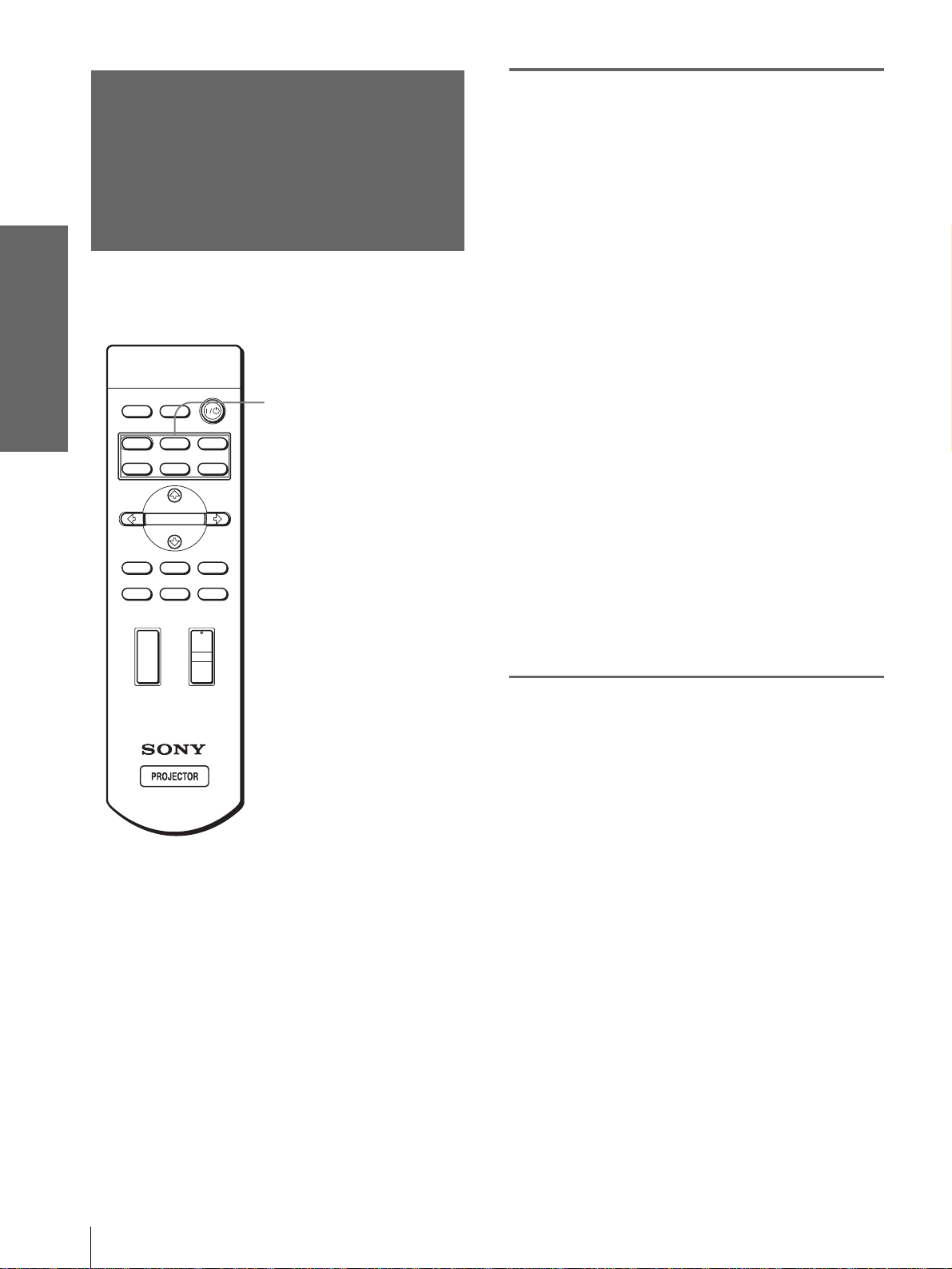
Inserting the batteries into the remote
control
Insert the batteries E side first as sho wn
in the illustration.
Inserting them forcibly or with the
polarities reversed may cause a short
circuit and may generate heat.
GB
6
Unpacking
Page 7
Step 1: Installing
the Projector
You can obtain good picture quality even when you
project the picture from the side of the screen (“Side
Shot”) (1 page 10). You can enjoy home
entertainment with this projec tor in v arious situ ations.
Connections and
Preparations
Watching sports, etc. with your company
Enjoying home theater
Enjoying video games on a large screen
Viewing images, recorded by a digital
camera and stored in the “Memory Stic k,” on
a large screen
Before Setting Up the
Projector
Do not place the projecto r in the follo wing sit uations,
which may cause malfunction or damage to the
projector.
Poorly ventilated
Step 1: Installing the Projector
7
GB
Page 8
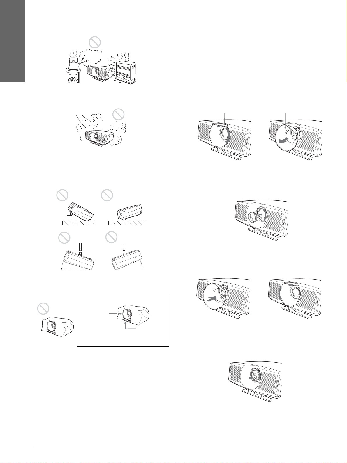
Connections and
Preparations
Highly heated and humid
Very dusty and ext remely smoky
Do not use the projector under the following
conditions:
Tilting the unit extremely
Using the supplied Cinema Filter
The Cinema Filter is supplied with the projector,
allowing you to receive higher contrast color and
emphasized black color by attaching or removing.
Use it according to preference.
To attach the Cinema Filter
1 Detach the lens hood stopper to remove
the lens hood.
Lens hood stopper Lens hood
2 Insert the Cinema Filter, aligning i ts screw
with the thread around the projector’s
lens, then turn the Filter clockwise.
15˚
15˚
Blocking the ventilation holes
Ventilation
holes
(exhaust)
Ventilation
holes
(intake)
Note
Installing the unit at altitudes
When using the projector at an al tit ude of 1,50 0 m or
higher, turn on high altitude mode in the INSTALL
SETTING menu. Failing to set this mode when using
the projector at high altitudes could have adverse
effects, such as reducing the reliability of certain
components.
3 Attach the lens hood by turning it
countercloc kwise until it clic ks, and fix the
lens hood with the lens hood stopper .
To remove the Cinema Filter
Perform step 1 above, then turn the Cinema Filter
counterclockwise to remove.
GB
Step 1: Installing the Projector
8
Page 9
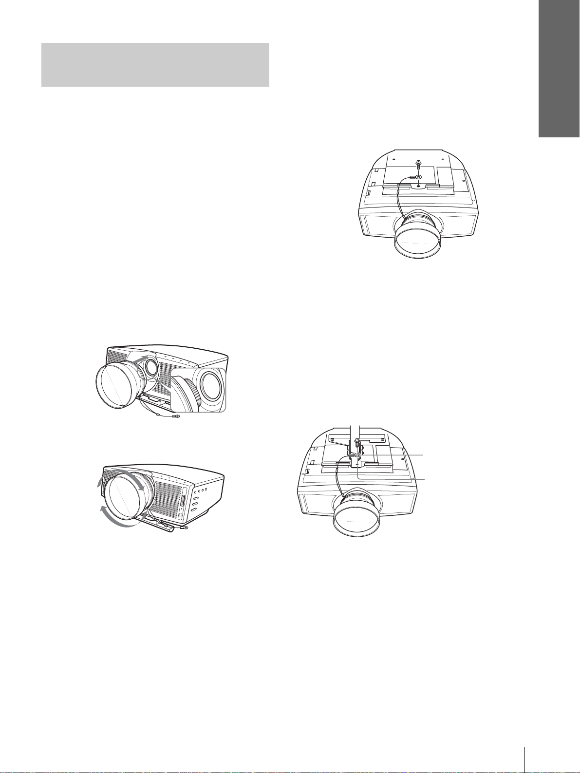
Using the Optional
Conversion Lens
Connections and
Preparations
projector to keep the Lens from contact with the floor or a
desk top. Otherwise, the Lens may malfunction if it
receives too much pressure from the weight of the
projector.
You can install the following two types of lenses
(optional) on the projector. For projection distances
when installing the Conversion Lens, see page 58.
• VPLL-CT10 Long Focused Conversion Lens
• VPLL-CW10 Short Focused Conversion Lens
Follow t he steps be low to install th e Con vers ion Lens.
For details o n installing the Lens, refer also to the
installation manual supplied with the Lens.
1 Turn off the power and disconnect the
power cord.
2 Remove the lens hood from the proj ector’s
lens, and remove the lens cap from the
Convers ion Lens.
3 Align the screw of the Conversion Lens
with the thread around the lens of the
projector as illustrated below.
6 Fasten the end of the safety wire of the
Conversion Lens to the bottom of the
projector using the screw supplied with
the Conversion Lens (M5×8, with washer).
Note
Be sure to fasten the end of the safety wire of the Lens to the
bottom of the projector.
When installing the projector on the ceil ing
Be sure to fasten the end of the safety wire of the Lens
to both the projector and the PSS-610 Projector
Suspension Support i n s te p 6, a s il lustrated below. In
this case, use the screw (M5×12, with washer)
supplied with the PSS-610.
First, place the PSS-610 ( 1 ) on the projector, then
place the safety wire ( 2 ) on the PSS-610.
4 Turn the Conversion Lens clockwise until
you hear it click.
Note
If the Conversion Lens is hard to turn, turn it slightly
counterclockwise first, then turn it clockwise.
5 Place a thick cloth (e.g., a cushion)
beneath the projector. Place the projector
face down.
Notes
• You cannot install the Conversion Lens on the projector’s
lens with the Cinema Filter attached. Remo v e the Cine ma
Filter when you install the Conversion Lens.
• The optional Conversion Lens projects from the top of the
projector when the Lens is installed on the projector. Before
installation, place a cloth of adequate thickness beneath the
End of safety wire
2
PSS-610 Projector
1
Suspension
Support
WARNING
Be sure to use the screw (M5×12 with washer) supplied with the
PSS-610. Never use the screw supplied with the Conversion Lens.
If you use the screw supplied with the Lens, the Lens may fall
from the projector and may cause injury.
Notes on installation of the optional Conversion Lens
• The Lens scratches easily, so when handling it, always place it
gently on a stable and level surface in a horizontal position.
• B e sure not to bump the Lens on the surface of the lens of the
projector.
• Avoid touching the Lens surface.
Step 1: Installing the Projector
9
GB
Page 10
Connections and
Preparations
To remove the installed Conversion Lens
1 Remove the end of the safety wire of the
installed Lens from the bottom of the
projector by removing the screw.
2 Turn the installed Lens counterclockwise
until it can be removed.
Notes
• Be sure not to drop the uninstalled Conversion Lens.
• When you adjust picture distortion us ing “V Keystone” or
“Side Shot” in the INSTALL SETTING menu with the
optional Conversion Lens attached to the projector, the
aspect ratio of the original picture may not be correctly
displayed.
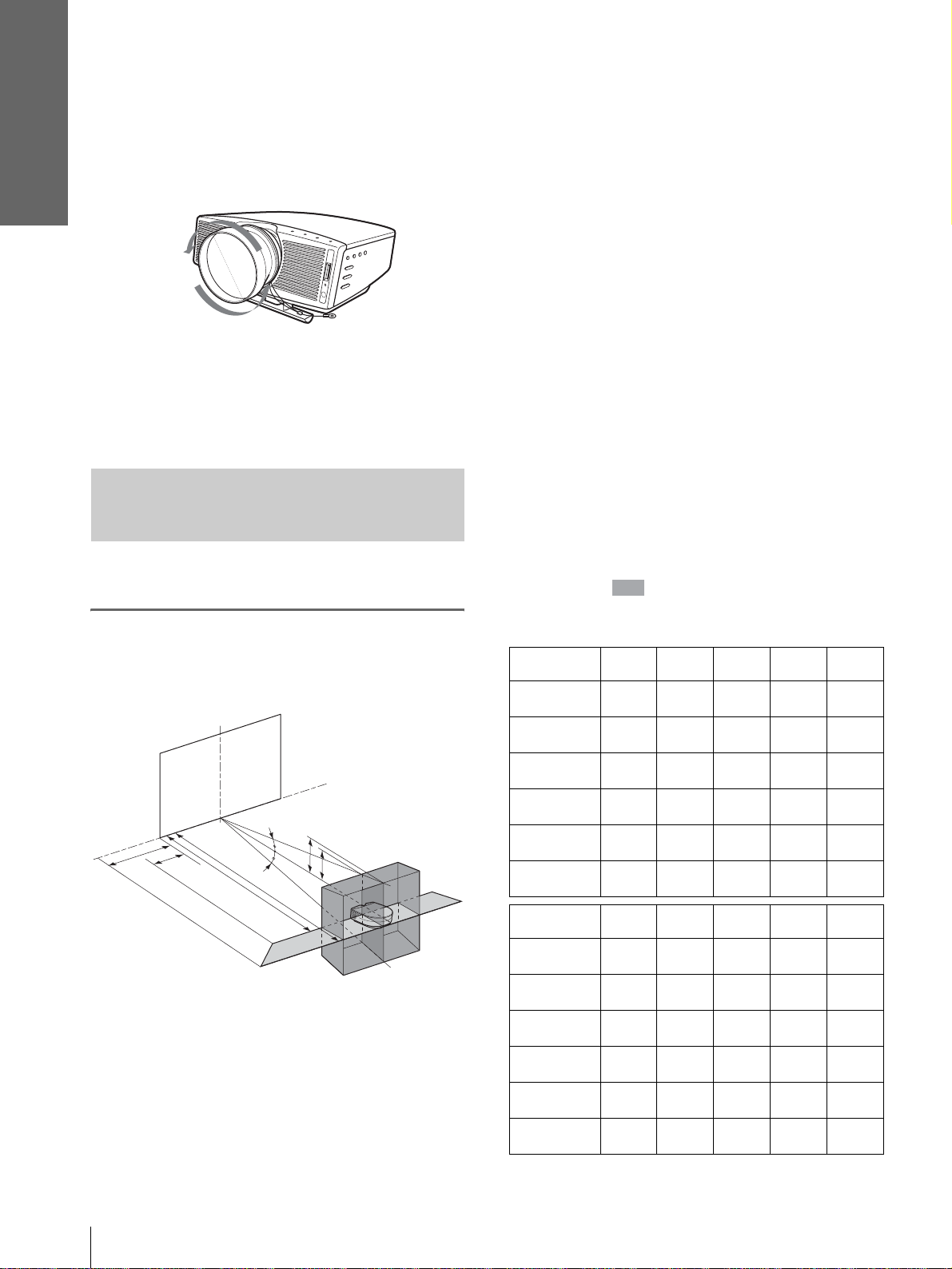
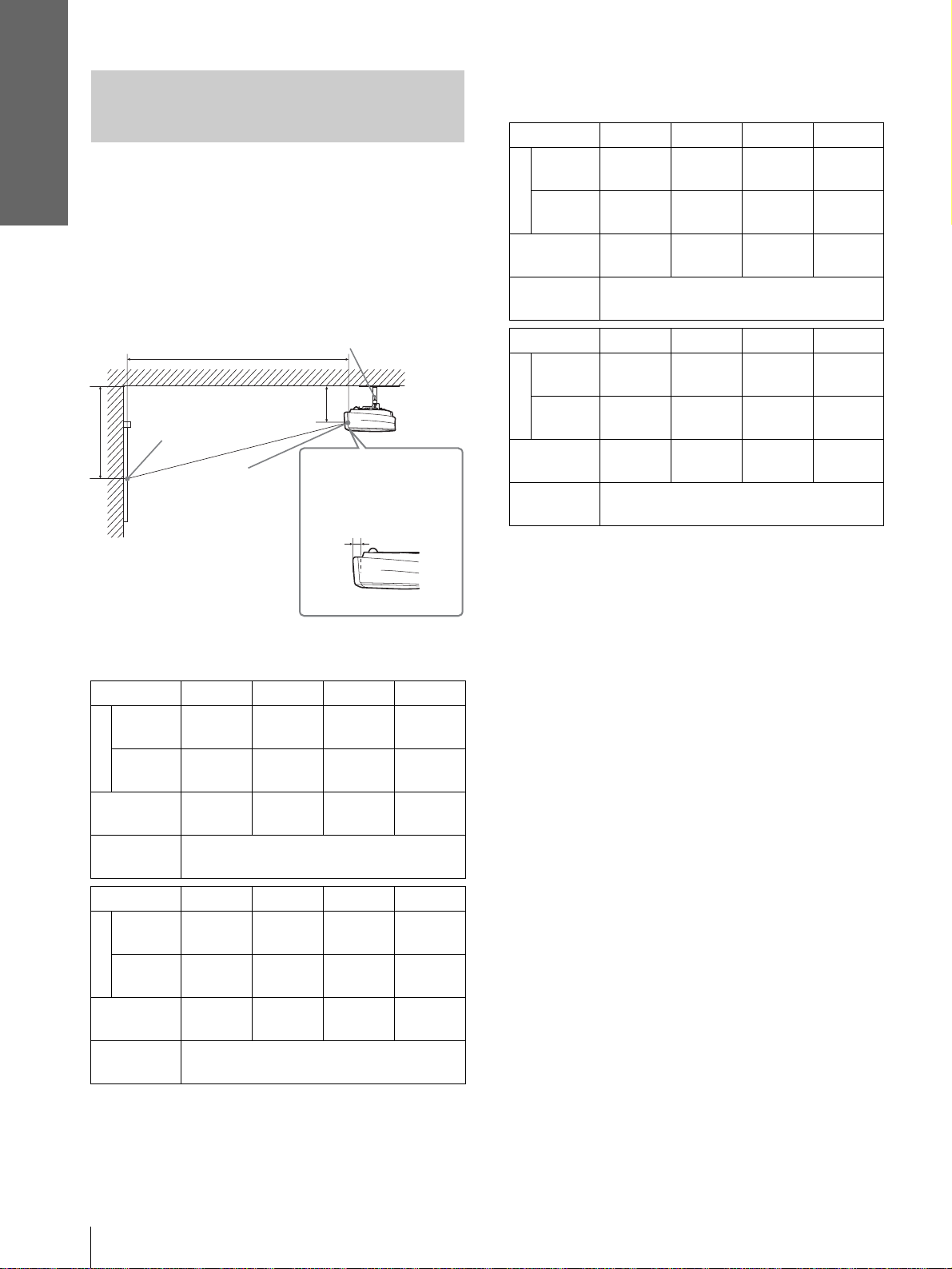
Installing the Projector and a
Screen — Floor Installation
The installation distance between the projector and
screen varies depending on the size of the screen.
1
Determine the ins tallation
position of the projector and
screen.
Screen
d
c
a
12˚
f
f
12˚
b
e
b: Maximum projection distance between the
screen and the center of the projector’s lens
when you place the projector on the side, or
when you place the projector wit h the cente r
of the screen and the center of the lens
aligned.
c: Maximum horizontal distance between the
right/left end of the screen and the center of
the projector’s lens when the projector is
placed on the side (when you use projection
distance a)
d: Maximum horizontal distance between the
right/left end of the screen and the center of
the lens when the projector is placed on the
side (when you use projection distance b)
e: Maximum vertic al distance from the bottom
of the screen to the center of the projector’s
lens when you place the pro jector on the side
(when you use projection distance a)
f: Maximum vertical distance from the bottom
of the screen to the center of the projector’s
lens when you place the pro jector on the side
(when you use projection distance b)
When projecting using both “Side Shot ”
and “V Keystone” adjustments
Position the projector with the lens en d within
the area in the illustration, by using the
values a to f in the table below as a guide.
Unit: m (feet)
Screen size
(inches)
a
b
c
d
e
f
40 60 80 100 120
1.6
(5.2)
1.8
(5.9)
–0.1
(–0.3)
0.0
(0.0)
0.3
(1.0)
0.4
(1.6)
2.4
(7.9)
2.8
(9.2)
–0.1
(–0.3)
0.0
(0.0)
0.5
(2.0)
0.6
(2.0)
3.2
(10.5)
3.7
(12.1)
–0.2
(–0.6)
0.0
(0.0)
0.7
(2.3)
0.8
(2.6)
4.0
(13.1)
4.7
(15.4)
–0.2
(–0.6)
0.0
(0.0)
0.8
(2.6)
1.0
(3.3)
4.8
(15.7)
5.6
(18.4)
–0.3
(–1.0)
0.0
(0.0)
1.0
(3.3)
1.2
(3.9)
GB
10
Projector
a: Minimum projection distance between the
screen and the center of the projector’s lens
when you place the projector on the side
(“Side Shot”), or when you place the
projector with the cent er of the screen and the
center of the lens aligned.
Step 1: Installing the Projector
Screen size
(inches)
a
b
c
d
e
f
150 180 200 250 300
6.0
(19.7)
7.0
(23.0)
–0.3
(–1.0)
–0.1
(–0.3)
1.3
(4.3)
1.5
(4.9)
7.3
(24.0)
8.4
(27.6)
–0.4
(–1.3)
–0.1
(–0.3)
1.5
(4.9)
1.8
(5.9)
8.1
(26.6)
9.4
(30.8)
–0.4
(–1.3)
–0.1
(–0.3)
1.7
(5.6)
1.9
(6.2)
10.1
(33.1)
11.7
(38.4)
–0.5
(–1.6)
–0.1
(–0.3)
2.1
(6.9)
2.4
(7.9)
12.1
(39.7)
14.1
(46.3)
–0.6
(–1.6)
–0.1
(–0.3)
(8.2)
(9.5)
2.5
2.9
Page 11
Connections and
Preparations
Tip
The tables show the distances when projecting the
conventional video and 1080i format signals. Distances
used for projecting a 720p format signal, computer’s signal
and data stored in the “Memory Stick” are shown on page
57.
Note
When projecting with the optional Conversion Lens
attached, the values a, b, e and f are slightly different from
those in the table.
When projecting using “Side Shot”
adjustment only
Position the projector with the lens end within
the area in the illust ration, by using the
values a, b, c and d in the table below as a guide.
Unit: m (feet)
Screen
size
(inches)
a
b
c
d
Screen
size
(inches)
a
b
c
d
40 60 80 100 120
1.6
(5.2)
1.8
(5.9)
0.2
(0.7)
0.3
(1.0)
150 180 200 250 300
6.0
(19.7)
7.0
(23.0)
0.7
(2.3)
1.1
(3.6)
2.4
(7.9)
2.8
(9.2)
0.3
(1.0)
0.4
(1.3)
7.3
(24.0)
8.4
(27.6)
0.8
(2.6)
1.3
(4.3)
3.2
(10.5)
3.7
(12.1)
0.3
(1.0)
0.6
(2.0)
8.1
(26.6)
9.4
(30.8)
0.9
(3.0)
1.5
(4.9)
4.0
(13.1)
4.7
(15.4)
0.4
(1.3)
0.7
(2.3)
10.1
(33.1)
11.7
(38.4)
1.1
(3.6)
1.9
(6.2)
4.8
(15.7)
5.6
(18.4)
0.5
(1.6)
0.9
(3.0)
12.1
(39.7)
14.1
(46.3)
1.4
(4.6)
2.2
(7.2)
When projecting from the center
You can change the projection angle using the
adjuster. (1 page 18)
Position t he projector with the lens end within
the area in the illust ration, by using the
values a and b in the table below as a guide.
Screen
size
(inches)
a
b
Screen
size
(inches)
a
b
2
Project an image on the screen
40 60 80 100 120
1.5
(4.9)
1.8
(5.9)
150 180 200 250 300
5.8
(19.0)
7.0
(23.0)
2.3
(7.5)
2.8
(9.2)
7.0
(23.0)
8.4
(27.6)
3.1
(10.2)
3.7
(12.1)
7.8
(25.6)
9.4
(30.8)
3.9
(12.8)
4.7
(15.4)
9.7
(31.8)
11.7
(38.4)
and adjust the picture so that it
fits the screen. (1 page 16)
T o project an image, connec t video equipment to
the projector. (1 page 13)
Unit: m (feet)
4.6
(15.1)
5.6
(18.4)
11.7
(38.4)
14.1
(46.3)
Tip
The tables show the distances when project ing the 15kHz
RGB/component, progressive component, DTV (480i/
480p/575i/575p), composite video and Y/C video signals.
Distances used for projecting a 1080i/720p format signal,
computer’s signal and data stored in the “Memory Stick”
are shown on page 57.
Note
If you project the picture using “Side Shot” only, set “V
Keystone” in the INST ALL SETTING menu to “Manual,”
and adjust the level to “0.”
Step 1: Installing the Projector
11
GB
Page 12
Connections and
Preparations
When using the 4:3 aspect ratio screen
Installing the Projector and a
Screen — Ceiling In stallation
Use the PSS-610 Projector Su spension Suppor t when
you install the projector on a ceiling.
a: Distance between the center of the lens and the
screen
b: Distance between the ceiling and the center of the
lens
x: Distance between the ceiling and the center of the
screen
PSS-610 Projector Suspension
Support (not supplied)
a
Ceiling
b
Distance from the
front of the cabinet
and the center of the
lens
61.5 mm (2
1
/2 inches)
Standard lens
x
Center of the
screen
Center of
the lens
SS (inches) 80 100 120 150
Minimum
a
Maximum
x
b
SS (inches) 180 200 250 300
Minimum
a
Maximum
x
b
To calculate the installatio n measurements (SS: Screen Size)
a (minimum) ={(SS × 33.56/0.7240) – 58.520408} × 1.025
a (maximum) ={(SS × 41.35918 19/0.72 40) – 57.1 81415} × 0.9 75
x = b + (SS/0.7240 × 5.516)
3741
3
(147
4508
5
(177
b+609
(b+24)
When using the PSS-610, adjustable with
243/268/293/343/368/393 mm
8493
3
(334
10212
1
(402
b+1371
(b+54)
When using the PSS-610, adjustable with
243/268/293/343/368/393 mm
/8)
/8)
/8)
/8)
4692
(184 3/4)
5648
(222 1/2)
b+762
(b+30)
9443
(371 3/4)
11353
(447)
b+1524
(b+60)
Unit: mm (inches)
5642
(222 1/8)
6789
(267 3/8)
b+914
(b+36)
11819
(465 1/2)
14205
(559 1/8)
b+1905
(b+75)
(278 1/2)
(334 3/4)
(558 3/4)
(671 3/4)
7067
8501
b+1143
(b+45)
14195
17057
b+2286
(b+90)
When using the 16:9 aspect ratio screen
Unit: mm (inches)
SS (inches) 80 100 120 150
/8)
4638
(182 3/4)
5584
(219 3/4)
b+753
(b+29 3/4)
9727
(383 1/8)
11694
(460 3/8)
b+1569
(b+61 7/8)
Minimum
a
Maximum
x
b
SS (inches) 180 200 250 300
Minimum
a
Maximum
x
b
To calculate the installatio n measurements (SS: Screen Size)
a (minimum) ={(SS × 33 .5 6/0 . 8 78 8) – 56.520408} × 1.025
a (maximum) ={(SS × 42.359182/0.8788) – 57.18141} × 0.975
x = b + (SS/0.8788 × 5.516)
3072
(121)
3704
3
(145
b+502
(b+19
When using the PSS-610, adjustable with
243/268/293/343/368/393 mm
6987
1
(275
8404
3
(330
b+1130
(b+44
When using the PSS-610, adjustable with
243/268/293/343/368/393 mm
/4)
7
/8)
/4)
/4)
1
/2)
3855
5
(151
4644
(182 3/4)
b+628
(b+24 3/4)
7770
(306)
9344
(367 7/8)
b+1255
(b+49 1/2)
5812
(228 7/8)
6994
(275 1/4)
b+924
(b+37 1/8)
11685
(460)
14044
(552 7/8)
b+1883
(b+74 1/4)
Attaching the projector suspension
support PSS-610
When installing the projector on the ceiling, use the
PSS-610 Projector Suspension Support. For more
details on the ceiling installation, refer to the
Installation manual for Dealers of the PSS-610. The
installation measu rements are shown be low when you
install the projector on the ceiling.
GB
12
Step 1: Installing the Projector
Page 13
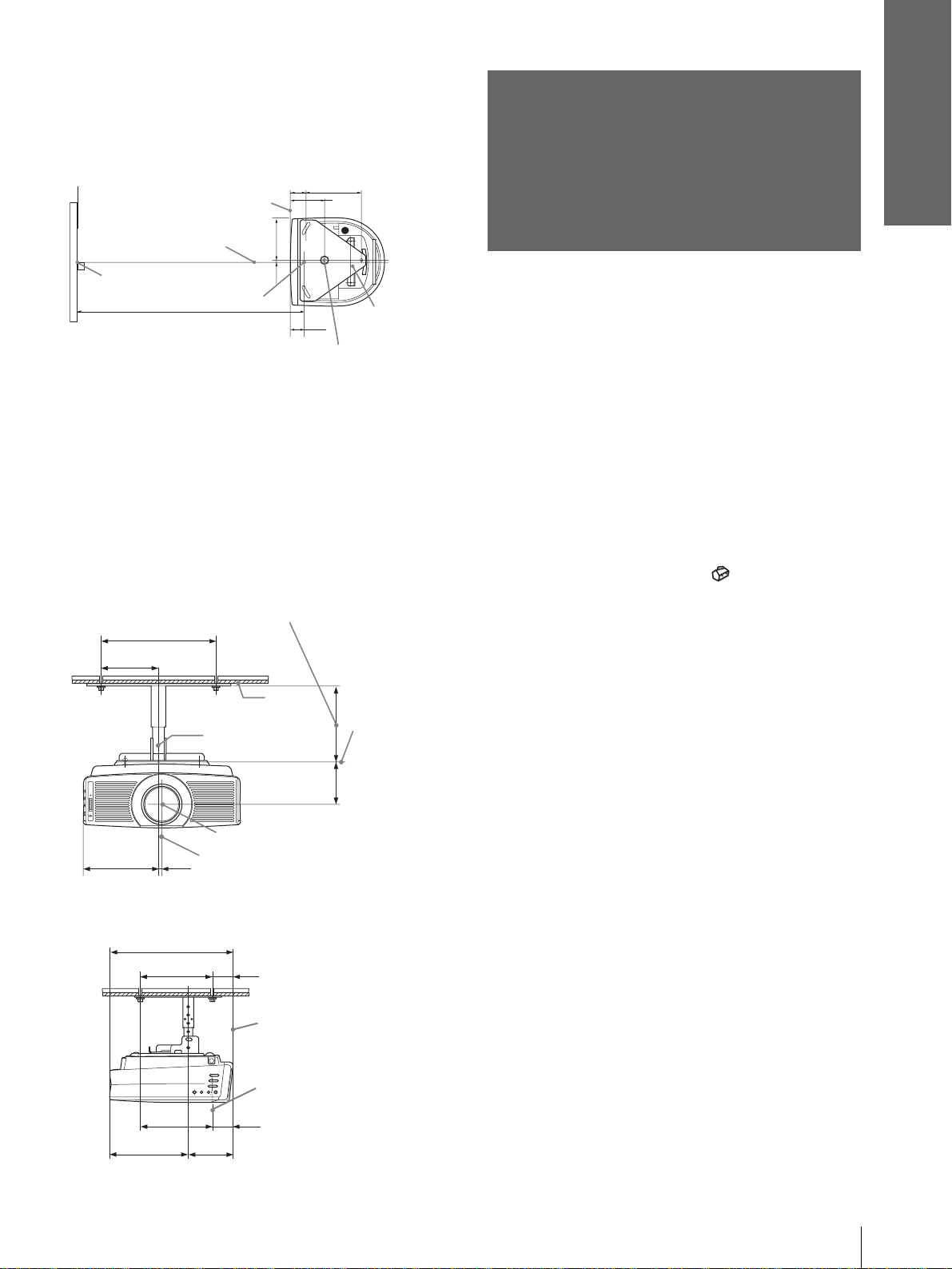
Installation diagram
Connections and
Preparations
Top view
Align the center of the len s with the center of the
screen.
62.1
216.6
1
5
/2)
(2
/8)
(8
Front of the cabinet
165
Center of the unit
Center of the screen
1
/2)
(6
7.9
5
(
/16)
Center of the lens
Distance between the screen
and the center of the lens
134.2
3
(5
/8)
61.5
Upper ceiling
1
(2
/2)
mount bracket
Center of the supporting pole (The center of the
supporting pole is different from that of the unit.)
Front view
The lens is of fset 7 .9 mm (
5
/16 inch) to the right from
the center of the supporting pole. When mounting,
take care to align th e center of the lens wi th the center
of the screen; not the center of the supporting pole.
Distance between the ceiling and the surface of
the mount bracket
Using adjustment pipe (b): 150/175/200 mm
(6 / 7 / 7
Using adjustment pipe (c): 250/275/300 mm
(9
125 (5)
7
/8 inches)
7
/8 / 107/8 / 117/8 inches)
250 (9 7/8)
Ceiling
Center of the
supporting pole
The bottom
surface of the
mount
bracket
Step 2:
Connecting the
Projector
When making connections, be sure t o do the
following:
• Turn off all equipment before making any
connections.
• Use the proper cables for each connection.
• Insert the cable plugs properly; plugs that are not
fully inserted often generate noise. When pulling
out a cable, be sure to pull it out f rom the plug , not
the cable itself.
• Refer to the ope rating i nstructi ons of the connecte d
equipment.
• When you connect your projector to PJ MULTI or
DVI connector, select the input signal with the
“Input-A Signal Sel.” or “Digital Signal Sel.”
setting in the SET SETTING menu. (1 page
29)
Note
Before you change the “Digital Sig nal Sel.” setting, disconnect
the DVI cable and turn of f the dig ital tune r, etc.
1
165 (6
/2)
Side view
234.3 (9 1/4)
7.9 (5/16)
368.5 (14 5/8)
216.6 (8
5
217.2 (8
Center of the lens
Center of the unit
62.1
5
/8)
/8)
134.2 (5 3/8)
(2
61.5
(2
1
/2)
1
/2)
93.3
3
/4)
(3
Front of the cabinet
Center of the lens
Unit: mm (inches)
Step 2: Connecting the Projector
13
GB
Page 14
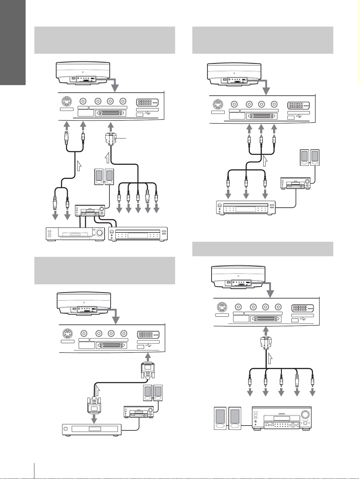
Connections and
Preparations
Connecting with Video
Equipment
Rear of the projector
S VIDEO
INPUT
S video or
video cable
(not supplied)
to S
video
or
video
output
VIDEO
Audio
amplifier
L
PJ MULTI
R
YP
B/CB PR/CR
Signal interface
cable (supplied)
Active
speakers
Y
R
L
with SONY logo
upside
to component
output
P
R/
B/
P
R
B
C
C
DVI
(FOR SERVICE USE)
S
Video
Video
Connecting a D VD Player Equipped
With the Component Output
Rear of the projector
VIDEO
S VIDEO
INPUT
PJ MULTI
Y
DVD player with component video
connectors, etc.
B/CB PR/CR
YP
Y
PB/
B
C
P
C
B/
B
PR/
C
R
PR/
C
R
Audio
amplifier
DVI
(FOR SERVICE USE)
Active
speakers
Video equipment
DVD player
Connecting a Digital Tuner
Using the DVI Connector
Rear of the projector
VIDEO
S VIDEO
INPUT
PJ MULTI
DVI cable (SMF-421, etc.,
to DVI output
Digital tuner, etc.
B/CB PR/CR
YP
not supplied)
speakers
DVI
(FOR SERVICE USE)
Active
Audio
amplifier
Connecting an AV Amplifier
Rear of the projector
YP
VIDEO
S VIDEO
INPUT
PJ MULTI
Signal interface cable
(supplied)
to component
video output
Y
Active speakers
B/CB PR/CR
P
B/
PR/
C
C
B
R
AV amplifier
DVI
(FOR SERVICE USE)
to S Video or
Video output
S
Video
Video
GB
14
Step 2: Connecting the Projector
Page 15
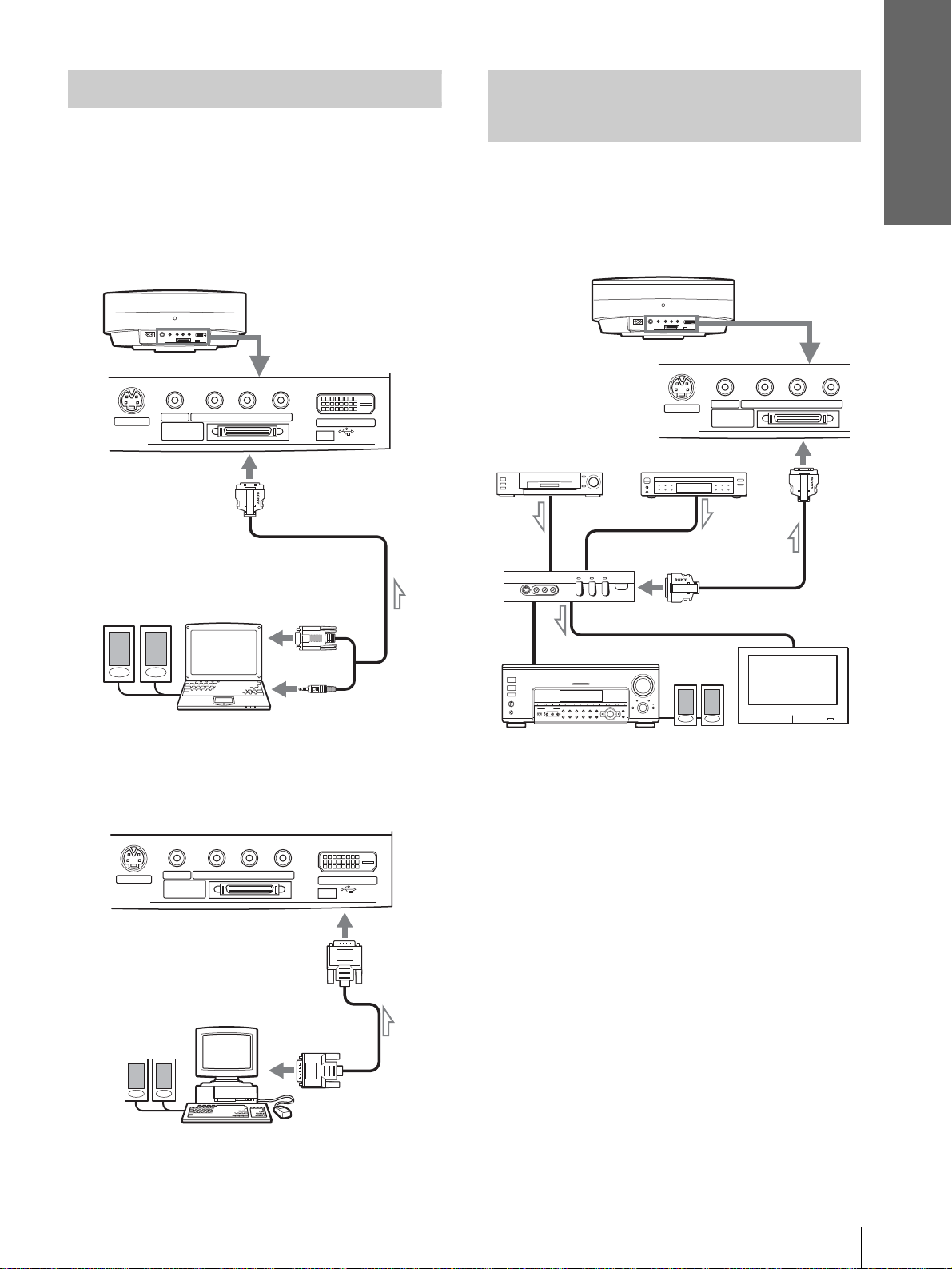
Connections and
d
Preparations
Connecting a Computer
When connecting to an analog connector
To hear the sound from a computer, use the speakers
built in the computer or connect the activ e speakers t o
the computer.
Note
Even if you connect the signal interface cable to the audio output
on the computer, there is no sound output from t he projector.
Rear of the projector
S VIDEO
INPUT
Active
speakers
VIDEO
PJ MULTI
B/CB PR/CR
YP
DVI
(FOR SERVICE USE)
Signal interface cable
(SIC-HS30, not supplied)
to monitor output
Connecting Using the
Optional Interface Unit
Using the optional interface unit allows you to
connect various video equipment, and to select the
output to the projector or TV from the connected
equipment simply by switching the select switch on
the interface unit.
Rear of the
projector
VIDEO Y PB/CB PR/CR
S VIDEO
PJ MULTI
PJ multi cab le (supplie
with the IFU-HS1)
VCR, etc.
INPUT
DVD player, etc.
Interface unit
(IFU-HS1, not supplied)
to PJ multi
output
Computer
When connecting to the DVI connector
Rear of the projector
S VIDEO
INPUT
Active
speakers
VIDEO
YP
PJ MULTI
B/CB PR/CR
DVI cable (SMF -421, etc.,
not supplied)
to monitor
output
Computer
DVI
(FOR SERVICE USE)
Audio amplifier
Active
speakers
TV
Step 2: Connecting the Projector
15
GB
Page 16
Connections and
Preparations
1
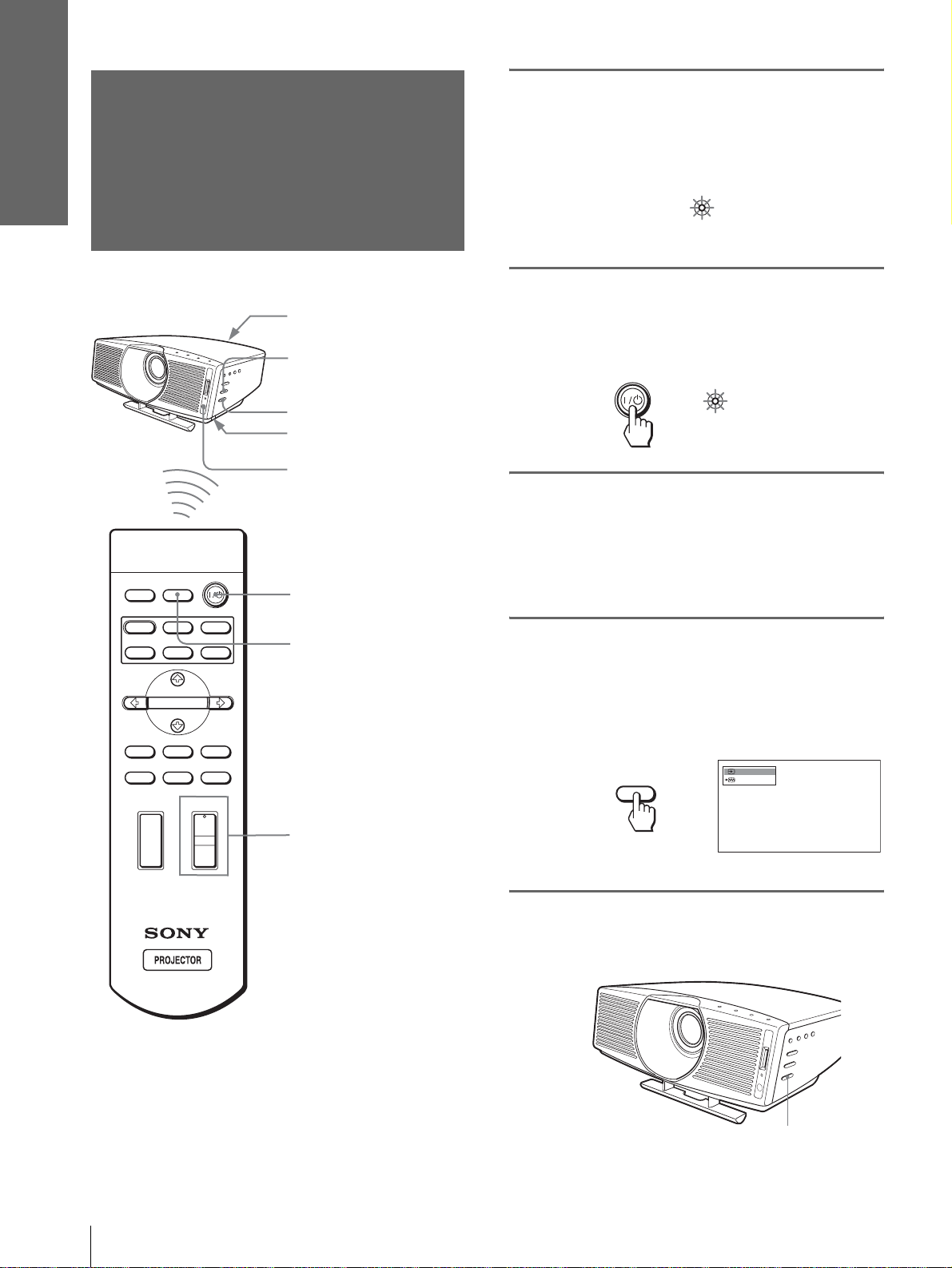
Step 3: Adjusting
Plug the AC po wer cord into a
wall outlet.
the Picture Size
The ON/STANDBY indicator lights in red and
the projector goes into standby mode.
and Position
Rear remote control
detector
6
5,7
Adjuster adjustment
button
Front remote control
detector
INPUTLIGHT
2
STANDARD
USER 2
ENTER
MS SLIDE
LENS
+
–
CINEMA
USER 3USER 1
MENUAPA
RESET
4
6
DYNAMIC
PICTURE MODE
WIDE MODE
VOLUME SIDE SHOT
+
–
ON/
Lights in red.
STANDBY
2
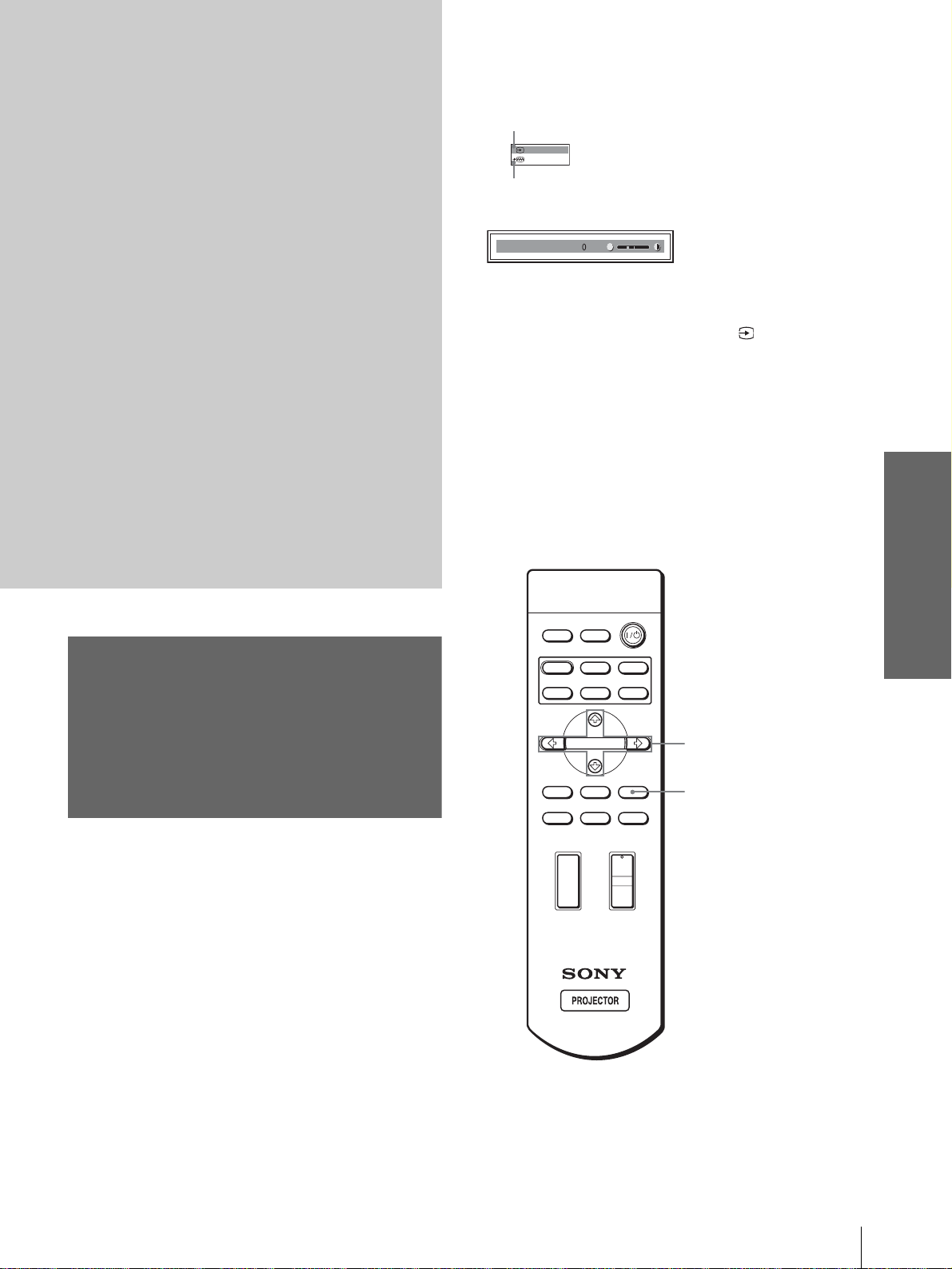
Press the [/1 (on/standby)
switch to turn on the pr ojector.
The ON/STANDBY indicator lights in green.
ON/
STANDBY
Lights in green.
3
Turn on the equipment
connected to the projector.
Refer to the operating instructions of the
connected equipment.
4
Press INPUT to project the
picture on the screen.
Each time you press the button, the input
indication changes. (1 page 21)
Video 1
INPUT
NTSC 3.58
GB
Tip
The ? /
1 (on/standby), INPUT, MENU, and m/M/</,/
ENTER (joystick) buttons on the side panel of the pr oj ec to r
function the same as those on the remote control.
16
Step 3: Adjusting the Picture Size and Position
5
Adjust the focus roughly using
the FOCUS +/– button .
FOCUS +/– button
Page 17
6
Adjust the size and position of
the picture to fit the screen.
When projecting using both “Si de Shot” a nd
“V Keystone” adjustments
1 Use the adjuster to adjust the vertical
position.
If you set “V Keystone” in the INSTALL
SETTING menu to “Auto” (1 page 29), the
vertical distortion will be automatically corrected.
For how to use the adjuster, see “Usi ng the
adjuster” on page 18.
Note
The “V Ke ystone” adjustment ma y no t cor r e c t t rapezoidal
distortion pe rfectly , depend ing on the ro om temperatur e or the
screen angle.
Connections and
Preparations
SIDE SHOT
Press SIDE SHO T + if the right si de is longer . To fineadjust the distortion, press M or m.
When projecting using “Side Shot”
adjustment only
2 Adjust so that the left or right side of the
picture fits that of the screen.
If you position the proj ector on the le ft sid e of the
screen, adjust so t hat the left si de of the pictur e fits
the left side of the screen. With the projector
positioned on the ri ght side, adjust so t hat the right
side fits the right side of the screen.
At the same time, align the bottom side of the
picture with that of the screen.
Screen
Picture
3 Adjust to correct horizontal trapezoidal
distortion using the SIDE SHOT + or –
button.
Press SIDE SHO T + or – so that the upper side of
the picture becomes pa ral l el to the bottom side. If
the left side is longer than the right side, press
SIDE SHOT –.
1 Set “V Keystone” in the INSTALL SETTING
to “Manual,” and set the level to “0” (1
page 29) or press RESET.
2 Adjust so that the left or right side of the
picture fits that of the screen.
If you position the proj ector on the le ft side of the
screen, adjust so th at the left si de of the pictur e fits
the left side of the screen. With the projector
positioned on the right side, adjust so t hat the right
side fits the right side of the screen.
At the same time, adjust the vertical size of the
aligned side of the picture to fit the screen using
ZOOM +/–.
Picture
3 Adjust to correct horizontal trapezoidal
distortion using the SIDE SHOT + or –
button.
For how to correct, see step 3 in
projecting using both
Keystone” adjustments.”
Screen
“When
“Side Shot” and “V
Step 3: Adjusting the Picture Size and Position
17
GB
Page 18
Connections and
Preparations
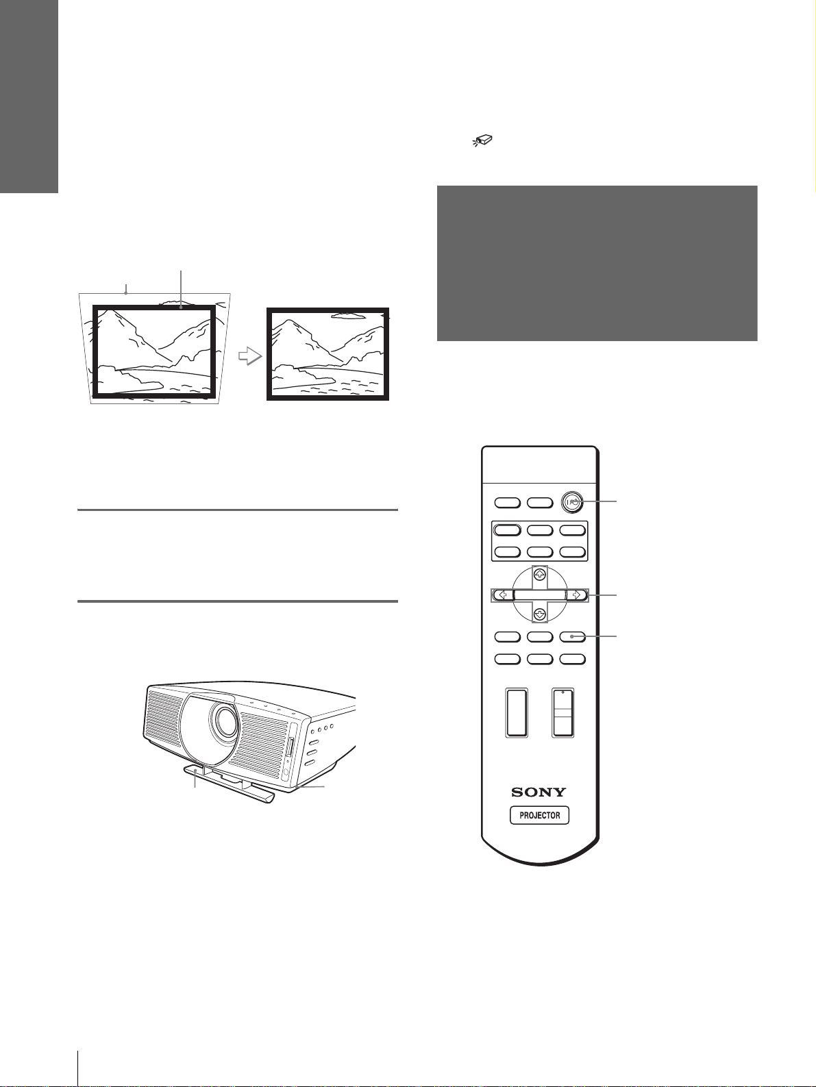
When projecting fr om the center
Adjust so that both the position and size of
the bottom side of the picture fit those of the
bottom side of the screen using the adjuster
and the ZOOM+/– button.
If you set “V Keystone” in the INSTALL SETTING
menu to “Auto” (1 page 29), the vertical distortion
will be automatically corrected.
For how to use the adjuster, see “Usi ng the adjust er.”
Picture
Note
The V Keystone adjustment may not correct trapezoidal distortion
perfectly, depending on the room temperature or the screen angle.
7
Press FOCUS +/– to adjust the
Screen
focus again.
Tip
When you press FOCUS +/– or ZOOM +/– in steps 5 to 7,
the built-in signal p attern is projec ted on the sc reen. If you
want to adjust the focus and picture size using the current
input signal, set “Test Pattern” in the INSTALL SETTING
menu to “Off.” (1 page 29)
Step 4:
Selecting the
Menu Language
You can select one of nine languages for displaying
the menu and other on-screen displays. The factory
default setting is English.
DYNAMIC
INPUTLIGHT
STANDARD
PICTURE MODE
USER 2
CINEMA
USER 3USER 1
2
Using the adjuster
Adjuster
Use the adjuster to adju st the picture position.
Lift the projector while pressing the adjuster
adjustment button, and release the button.
Holding the adjuster adjustment b utton presse d,
move the projector, then release the button at the
locked position.
Adjuster
adjustment
button
ENTER
MS SLIDE
MENUAPA
LENS
WIDE MODE
VOLUME SIDE SHOT
+
–
Tip
You can operate the menu using the joystick on the side panel of
the projector instead of the M/m/</,/ENTER buttons on the
remote control.
RESET
+
–
4
3
-
6
GB
18
Step 4: Selecting the Menu Language
Page 19
1
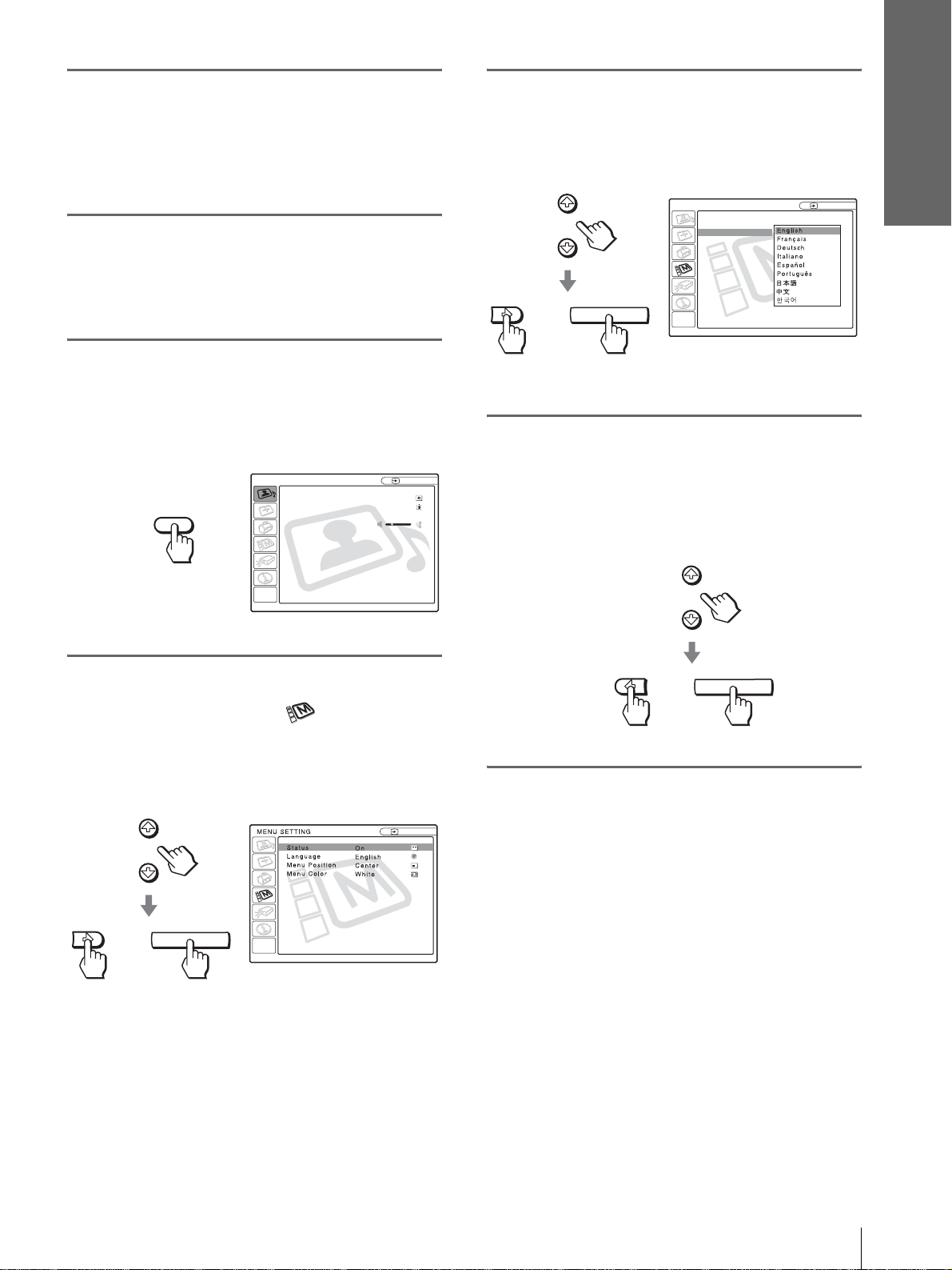
Plug the AC power cord into a
wall outlet.
The ON/STANDBY indicator lights in red and
the projector goes into standby mode.
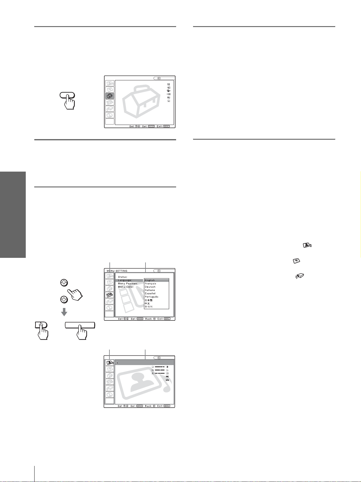
2
Press the [/1 (on/standby)
switch to turn on the projector.
The ON/STANDBY indicator lights in green.
3
Press MENU.
The menu appears.
The menu presently selected is shown as a
yellow button.
PICTURE SETTING
Picture Mode Standard
Adjust Picture...
MENU
Volume: 30
Input A
5
Press M or m to select
“Language”, and press , or
ENTER.
MENU SETTING
Status:
Language:
Menu Position:
Menu Color:
or
6
Press M or m to select a
ENTER
language, and press < or
ENTER.
The menu changes to the selected language.
Connections and
Preparations
Input A
4
Press M or m to select the
MENU SETTING menu, and
press , or ENTER.
The selected menu appears.
:
:
:
:
or
ENTER
Input A
A
To clear the menu
Press MENU.
or
ENTER
Step 4: Selecting the Menu Language
19
GB
Page 20
Projecting
Projecting the
This section describes how to operate the
projector to view the picture from the
equipment connected to the projector. It
also describes how to select the wide
screen mode or the quality of the picture to
suit your taste.
Picture on the
Screen
4
INPUTLIGHT
2
STANDARD
USER 2
ENTER
MS SLIDE
LENS
CINEMA
USER 3USER 1
MENUAPA
RESET
+
DYNAMIC
PICTURE MODE
WIDE MODE
VOLUME SIDE SHOT
+
–
–
GB
20
Projecting the Picture on the Screen
Page 21
1
Plug the AC power cord into a
wall outlet.
The ON/STANDBY indicator lights in red and
the projector goes into standby mode.
ON/
Lights in red.
STANDBY
2
Press the [/1 (on/standby)
switch to turn on the projector.
The ON/STANDBY indicator lights in green.
ON/
STANDBY
Lights in green.
3
Turn on the equipment
connected to the projector.
Refer to the operating instructions of the
connected equipment.
To view the picture from
Video equipment connected to
VIDEO INPUT on the projector
Video equipment connected to S
VIDEO INPUT on the projector
RGB/component equipment
connected to PJ MULTI INPUT via
the optional signal interface cable or
the interface unit
Video equipment connected to PJ
MUL TI INPUT via the opti onal signa l
interface cable or the interface unit
Video equipment equippe d with S
VIDEO connected to PJ MULTI
INPUT via the optional signal
interface cable or the interface unit
Component equipment connected to
Y / P
B/CB / PR/CR on the projector
Digital video equipment connected to
DVI connector on the projector
“Memory Stick” inserted into the
“Memory Stick” slot
*
Set the “Input-A Signal Sel.” or “Digital Signal Sel.” setting in
the SET SETTING menu according to the input signal. (1
page 29)
Press INPUT to
display
Vi de o 1
S-Video 1
*
Input-A
Vi de o 2
S-Video 2
Component
Digital*
MS
Projecting
4
Press INPUT repeatedly to
select the input you want to
project on the screen.
Display the indication of the input you want.
Example:To view the picture from the video
equipment connected to the VIDEO
INPUT jack.
Video 1
INPUT
NTSC 3.58
Note
Before you change the “Digital Sig nal Sel.” setting, disconnect
the DVI cable and turn of f the dig ital tune r, etc.
5
Press ZOOM +/– to adjust the
size of the picture.
ZOOM +/– button
Projecting the Picture on the Screen
21
GB
Page 22
6
Press FOCUS +/– to adjust the
focus.
Adjust to obtain sharp focus.
Selecting the Wide
Screen Mode
Projecting
FOCUS +/– button
To turn off the power
1 Press the [/1 (on/standby) switch.
A message “POWER OFF?” appears on the
screen.
2 Press the [/1 switch again.
The ON/ST ANDBY indicator flashes in green and
the fan contin ues to run to r educe the int ernal heat.
Also, the ON/ST ANDBY indicator flashes quickly
during which you will not be able to light up the
ON/STANDBY indicator with the [/1 switch.
3 Unplug the AC power cord from the wall
outlet after the fan stops running and the
ON/STANDBY indicator lights in red.
Y ou can enjoy variou s wide screen mode according to
the video signal re ceived. You can also select it using
the menu. (1 page 28)
INPUTLIGHT
STANDARD
USER 2
ENTER
MS SLIDE
LENS
CINEMA
USER 3USER 1
+
–
MENUAPA
RESET
WIDE MODE button
DYNAMIC
PICTURE MODE
WIDE MODE
VOLUME SIDE SHOT
+
–
GB
You can turn off the project or b y ho lding t he [/1 (on/
standby) switch for about one second, instead of
performing the above steps.
22
Selecting the Wide Screen Mode
Press WIDE MODE.
Each time you press the button, you can select
the “Wide Mode” setting.
Page 23
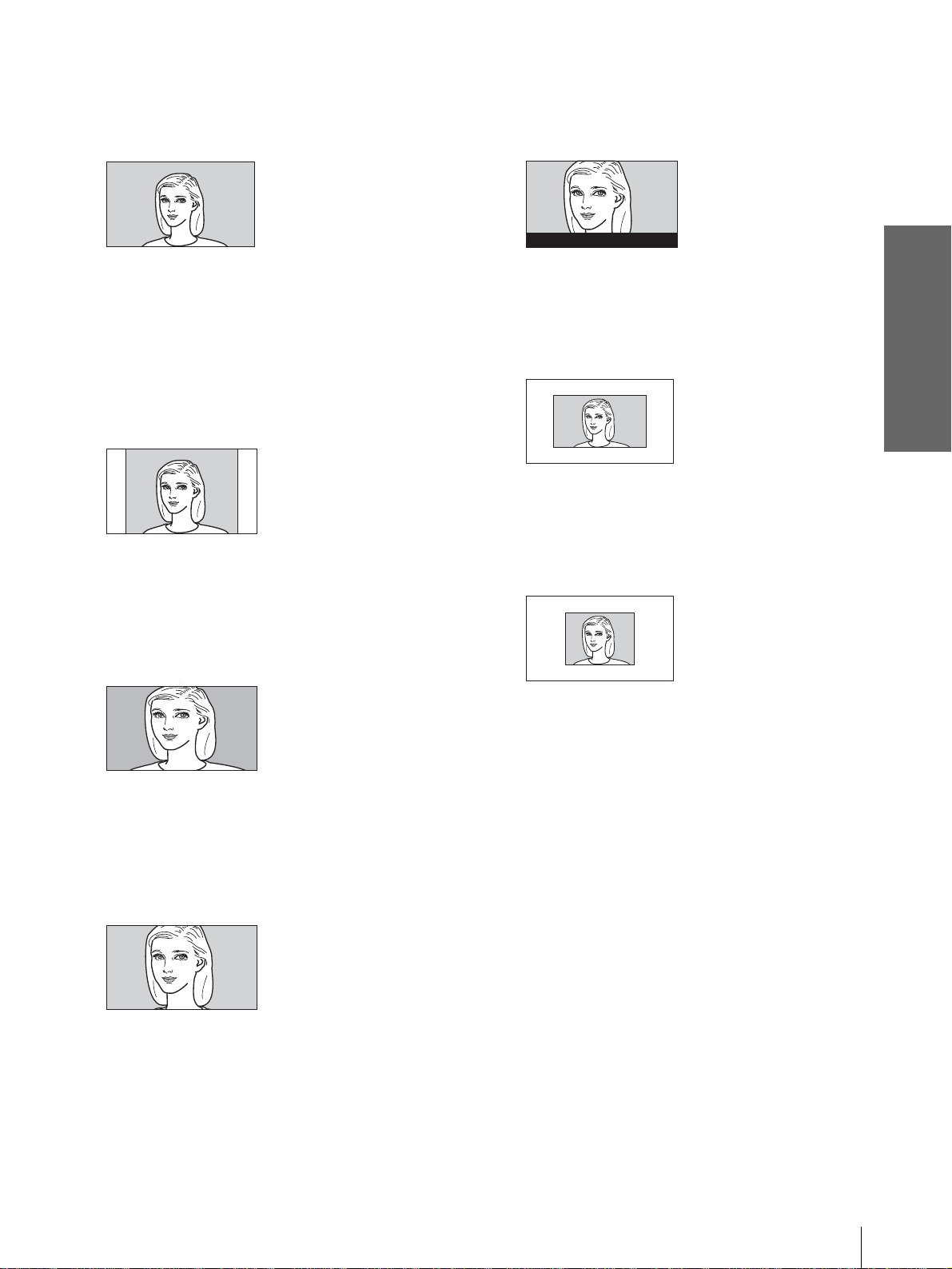
Full
A 16:9 squeezed picture is displayed with the
correct aspect ratio. A 4:3 picture is enlarged
horizontally to fit the 16:9 screen.
Subtitle
The subtitle area is compressed and displayed in
the lower part of the screen. Use this mode to
view a movie with subtitles.
Good-bye
Tip
Squeezed: An original 16:9 aspect ratio picture is recorded
horizontally compressed to a 4: 3 picture.
Normal
A picture with normal 4:3 aspect ratio is
displayed in the center of the screen to fil l the
vertical screen size.
Wide Zoom
A 4:3 aspect ratio picture is enlarged and the
upper and lower portions of the picture are
compressed to fi t the 16:9 screen. Use thi s mode
to view news, variety shows, etc.
Zoom
A normal 4:3 aspect ratio picture is enlarged
vertically and horizontal ly in the same ratio to
fill the 16:9 scr een. This mode is ideal for
viewing a wide-format movie.
Full Through
One-to-one mapping is done on a squeeze d 16:9
picture. It is displayed in the center of the
screen.
Normal Through
One-to-one mapping is done on a 4:3 normal
aspect ratio picture. It is displayed i n th e center
of the screen.
Notes
• You can adjust the vertical position of the picture with
“V Position” in the INPU T SETTING menu onl y when
“Zoom” or “Subtitle” is selected.
• You can adjust the position of the subtitles with “Title
Area” in the INPUT SETTING menu only when
“Subtitle” is selected.
• If “Full Through” or “Normal Through” is selected when
a video signal except for DTV (720/60p, 720/50p, 1080/
60i or 1080/50i) or 1080/24Psf signal is input, you
cannot adjust “V Keystone” or “Side Shot” in the
INSTALL SETTING menu.
Projecting
Notes on selecting the wide screen mode
• Select the wide screen mode taking into account
that changing the aspect rati o of the ori ginal pict ure
will provide a different look from that of the
original image.
• Note that if the projector is used for profit or for
public viewing, modifying the original picture by
switching to the wide mode may constitute an
infringement of the rights of authors or producers,
which are legally protected.
Selecting the Wide Screen Mode
23
GB
Page 24
Selecting the
Picture Viewing
Press one of the PICTURE
MODE buttons (DYNAMIC,
STANDARD, CINEMA and
USER 1, 2 and 3).
Projecting
Mode
You can select the picture viewing mode that best
suits the type of program or room condition.
INPUTLIGHT
STANDARD
DYNAMIC
PICTURE MODE
USER 2
ENTER
MS SLIDE
LENS
WIDE MODE
VOLUME SIDE SHOT
+
–
+
–
CINEMA
USER 3USER 1
MENUAPA
RESET
PICTURE MODE buttons
DYNAMIC
STANDARD
CINEMA
USER 1, 2 and 3
DYNAMIC
Select for enhanced picture contrast and
sharpness.
STANDARD
Recommended for normal vie wi ng con dit ion in
your home.
Also select to reduce roughness when viewing
the picture with DYNAMIC.
CINEMA
Select for soft, film-like pictu re.
USER 1, 2 and 3
You can adjust the quality of the picture to suit
your taste and stor e the settings into the selec ted
memory of the projecto r . Press one of the USER
1, 2 and 3 buttons, then adjust the picture by
using the menus. The settings are stored, and
you can view the picture with the adjusted
picture quality by pre ssing t he b utto n. (1 page
27)
GB
24
Selecting the Picture Viewing Mode
Page 25
Display items
Using the
Menus
This section describes how to make
various adjustments and settings using the
menus.
Input signal indicator
Video 1
NTSC 3.58
Input signal setting indicator
Picture adjustment menu
Contrast
Input signal indicator
Shows the selected input channel. is displayed
when no signal is input. You can hide this indicator
using “Status” in the MENU SETTING menu.
Input signal setting indicator
For Input-A: Shows “Computer,” “Component” or
“Video GBR.”
For Digital : Shows “Computer” or “Video GBR.”
For V ideo/S V ideo input: Sho ws “ Auto” or the “Color
System” setting in the SET SETTING menu.
x
Using the Menus
Operation through
the Menus
The projector is equipped wi th an on-screen me nu for
making various adj ustment s and set ting s. The set ting
items are displayed in a pop-up menu or in a sub
menu. If you select an item name followed by dots
(...), a sub menu with setting items appear. You can
change the tone of the menu display and the menu
language displayed in the on-screen menu.
To change the menu language, see “Selecting the
Menu Language” on page 18.
INPUTLIGHT
STANDARD
DYNAMIC
PICTURE MODE
USER 2
ENTER
MS SLIDE
LENS
WIDE MODE
VOLUME SIDE SHOT
+
–
+
–
CINEMA
USER 3USER 1
MENUAPA
RESET
2-4
1
Operation through the Menus
25
GB
Page 26
1
Press MENU.
The menu appears.
The menu presently selected is shown as a
yellow button.
SET SETTING
Smart APA: On
Auto Input Search:
Input-A Signal Sel.:
MENU
Color System: Auto
Power Saving: Off
Illumination: Off
Off
Computer
Input A
4
Make the setting or adjustment
on an item.
When changing the adjustment level
To increase the value, press M or ,.
To decrease the value, press m or <.
Press ENTER to restore the original screen.
When changing the setting
Press M or m to change the setting.
Press < or ENTER to restore the original
screen.
2
Press M or m to select a menu,
and press , or ENTER.
To clear the menu
Press MENU.
The selected menu appears.
Using the Menus
To reset items that have been
adjusted
3
Press M or m to select an item
you want to adjust and press
, or ENTER .
The setting items are displayed in a pop-up
menu or in a sub menu.
Pop-up menu
Menu Setting items
or
ENTER
Input A
Select the item you want to reset, then press RESET.
“Complete!” appears on the screen and the setting is
reset to its factory preset value.
Items that can be reset are:
• “Contrast,” “Brightness,” “Color,” “Hue,”
“Sharpness” and “RGB Enhancer” in “Adjust
Picture...” of the PICTURE SETTING menu
• “Dot Phase,” “H Size” and “Shift” in “Adjust
Signal...” of the INPUT SETTING menu
• “V Keystone” (when set to “Manual”) and “Side
Shot” of the INASTALL SETTING menu
GB
26
Operation through the Menus
Sub menu
Menu Setting items
Graphics
High
Input A
PICTURE SETTING
ADJUST PICTURE
Contrast: 80
Brightness: 50
RGB Enhancer: 30
Gamma Mode:
Color Temp:
Standard
Page 27
Menu Lists
Menu Configurations
The projector is equipped with six pages. The items
that can be adjusted in each menu are described on
pages 27 to 29.
PICTURE SETTING menu
The PICTURE SETTING menu is used for adjusti ng
the picture. You can also adjust the v olume (av ai lable
only for “Memory Stick”).
INPUT SETTING menu
The INPUT SETTING menu is used to adjust the
input signal. You can adjust the size of the picture, and
select wide screen mode, etc.
SET SETTING menu
The SET SETTING menu is used for changing the
settings of the projector.
MENU SETTING menu
The MENU SETTING menu is used to change the
display position, int ensity of the backgrou nd pi ct ure ,
etc., of the menu screen.
INSTALL SETTING menu
The INST ALL SETTI NG menu is used for cor recting
distortion of the picture.
INFORMATION menu
The INFORMATION menu is used to display the
horizontal and ve rtical freq uencies of the in put signal
and the used time of the lamp.
Menu Items
Adjustable items are limited according to the input
signals. Items that cannot be adjusted are not
displayed in the menu. (1 page 61)
PICTURE SETTING
Item Description
Picture Mode You can select picture viewing mode that
Volume Adjusts the volume.
Adjust Picture…
Contrast The higher the setting, the greater the
Brightness The higher the setting, the brighter the
Color The higher the setting, the greater the
Hue The higher the setting, the more greenish
Sharpness The higher the setting, the sharper the
RGB
Enhancer
best suits the type of picture or the
environment.
Dynamic: Select for enhanced picture
contrast and sharpness.
Standard: Recommended for normal
viewing condition. Also select to reduce
roughness when viewing the picture
with Dynamic.
Cinema: Select for soft, film-like picture.
User 1, 2 and 3: You can adjust the
quality of the picture to suit your taste
and store the settings. Once the settings
are stored, you can view the picture with
the adjusted picture quality by pressing
the PICTURE MODE button.
To store the settings
1 Select User 1, User 2 or User 3.
2 Adjust the items you want in the
menus.
Items that can be stored are:
“Adjust Picture...” items other than
“Volume,” and “Wide Mode” setting
Tip
You can also adjust the picture quality
in “Dynamic”, “Standard” or “Cinema”
mode. To reset to the factory setting,
press RESET.
Tip
Audio is output only when a movie file
stored in a “Memory Stick” is played.
contrast. The lower the setting, the lower
the cotrast.
picture. The lower the setting, the darker
the picture.
intensity. The lower the setting, the lower
the intensity.
the picture becomes. The lower the
setting, the more purplish the picture
becomes.
picture. The lower the setting, the softer
the picture.
Adjusts the picture sharpness when
computer signals are input.
Using the Menus
Menu Lists
27
GB
Page 28
Item Description
Black Level
Adj (Adjust)
Emphasizes black color to produce a
bolder “dynamic” picture. Set according
to the input signal source.
High: Gives higher emphasis to the black
color.
Low: Gives lower emphasis to the black
color.
Off: Cancels this feature.
Gamma Mode Graphics: Reproduce s t he photos in
natural tones.
Text: Contrasts black and white. Suitable
for images that contain lots of text.
Color Temp. High: Gives the white colors a blue tint.
Middle: Gives the white colors a neutral
tint.
Low: Gives the white colors a red tint.
DDE
(Dynamic
Detail
Enhancer)
Off: Plays a video signal in an interlace
format without converting.
Progressive: Converts an interlace format
video signal to a progressive format .
Film: Normally, select this option.
Reproduces the 2-3 Pull-Down film
Using the Menus
sources with smoo th pic tu re mo v eme nt.
When the video signal with a format
other than the 2-3 Pull-Down is input,
“Progressive” is automatically selected.
Cinema Black Switches the lamp wattage during
projection.
On: Enhances the black by reducing the
lamp wattage.
Off: Normal wattage.
Tip
If “Cinema Bla ck” is set to “On,” the next time
the power is turned on, the lamp will use the
“Off” setting for the first time, and then go to
“On.”
INPUT SETTING
Item Description
Adjust Signal…
Dot Phase Adjusts the picture from a computer for
Item Description
Wide Mode You can select the 4:3 aspect ratio picture
mode, “Normal” and “Normal Through,”
and 16:9 aspect ratio picture mode,
“Full,” “W ide Zoom, ” “Zoom, ” “Subtitle”
and “Full Through.”
Full: The 16:9 squeezed* picture is
diplayed with the correct aspect. The
4:3 picture is e nlarged horizontally to
fit the 16:9 screen.
* squeezed: An original 16:9 aspect
ratio picture is recorded horizontally
compressed to be a 4:3 picture.
Normal: The picture with normal 4:3
aspect ratio is displayed to fill the
vertical screen size.
Wide Zoom: The picture with 4:3 aspect
ratio is enlarged and the upper and
lower portions of the picture are
compressed to fit the 16:9 screen. Use
this mode to view news, variety shows,
etc.
Zoom: The normal 4:3 aspect ratio
picture is enlarged verticall and
horizontally at the equal ratio to fill the
16:9 screen. The mode is ideal for
viewing a wide-format movie.
Subtitle: The subtitle area is compressed
and displayed at the lower part of the
screen. Use this mode to view a movie
with the subtitle.
Full Through: One-to-one mapping is
done on a squeezed 16:9 picture. It is
displayed in the center of the screen.
Normal Through: One-to-one mapping
is done on the picture with 4:3 aspect
ratio. It is displayed in the center of the
screen.
Note
If “Full Through” or “ N ormal Through” is
selected when a video signal except for DTV
(720/60p, 720/50p, 1080/60i or 1080/50i) or
1080/24Psf signal is input, you cannot adjust “V
Keystone” or “Side Shot” in the INSTALL
SETTING menu.
clearer picture after it is adjusted by
pressing the APA button.
H Size Adjusts the horizontal size of the picture
from a computer. The higher the setting,
the wider the picture. The lower the
setting, the narrower the picture.
Shift As the setting for H (horizontal)
increases, the picture moves to the right,
and as the setting decreases, the picture
moves to the left. Use < or , to adjust
the horizontal position.
As the setting for
V (vertical) increases,
the picture moves up, and as the setting
decreases, the picture moves down. Use
M or m to adjust the vertical position.
V Position Adjusts the vertical position of the picture
Title Area Adjusts the subtitle area. As the setting
For details, see “Selecting the Wide
Screen Mode” on page 22.
in wide screen mode. As the setting
increases, the picture moves up. As the
setting decreases, the picture moves
down.
Note
This item is adjustable only when “Zoom” or
“Subtitle” is selected.
increases, the subtitle area moves up. As
the setting decreases, the subtitle area
moves down.
Note
This item is adjustable only when “Subtitle” is
selected.
GB
28
Menu Lists
Page 29
SET SETTING
Item Description
Smart APA With this item set to On, the APA function
works automatically for a signal input from
a computer so that the picture can be seen
clearly. You can also activate the APA
function by pressing the AP A bu tton on the
remote control.
Tip
The APA (Auto Pixel Alignment) automatically
adjusts the input signal from a computer so that
the picture can be seen clearly.
Auto Input
Search
Set to On when an optional Interface Unit
such as the IFU-HS1 is connected to the PJ
MULTI connector on the projector.
Input-A Signal
Sel.
Selects the signal input from the equipment
by selecting “Input-A” with the INPUT
button.
Computer: Inputs the signal from a
computer.
Component: Inputs the component or
progressive component signal from a
DVD player, digital tuner, etc.
Video GB R: Inputs the signal from a TV
game or HDTV broadcast.
Digital Signal
Sel.
Selects the signal input from the equipment
by selecting “Digital” with the INPUT
button.
Computer: Inputs the signal from a
computer.
Video GB R: Inputs the signal from a
digital tuner, etc.
Note
Before you cha nge the “Digital Signal Sel .”
setting, disconnect the D VI cable and turn of f the
digital tuner, etc.
Color System Select the color system of the input signal.
Auto: Selects the color system of the input
signal automatically from among NTSC,
PAL, SECAM, NTSC
4.43, PAL-M or
PAL-N.
“NTSC3. 58”–“PAL-N”: Sets the color
system to the selected system manually.
Power Saving When set to On, the POWER SAVING
indicator lights. The projector goes into
power saving mode if no signal is input for
10 minutes, and the lamp goes out and the
cooling fan keeps running. In power saving
mode, no button functions for the first 60
seconds. It is cancelled when a signal is
input or any b utt on is pres sed. If you do not
set the projector to power saving mode,
select Off.
Illumination Turns on the illumination on the top panel
of the projector when set to On. It turns off
when set to Off.
MENU SETTING
Item Description
Status Set to Off to turn off the on-screen
Language Selects the lang ua g e used in the menu and
displays except for the menus, message
when turning off the power, and warning
messages.
on-screen dis plays. Available languages
are: English, French, German, Italian,
Spanish, Portuguese, Japanese, Chinese
and Korean.
Item Description
Menu Position Selects the display position from Top
Left, Bottom Left, Center, Top Right
and Bottom Right.
Menu Color Selects the tone of the menu display from
White or Black.
INSTALL SETTING
Item Description
V Keystone Corre cts the vertical trapezoidal distortion
of the picture. ( )
Auto: Normally set to this postion.
Manual: Sets a lower value (– direction)
when the bottom of the trapezoid is
longer than the top. Sets a higher value
(+ direction) when the top of the
trapezoid is longer than the bottom. If
you project the picture using “Side
Shot” only, set to “Manual,” and adjust
the level to “0.”
Note
The “V Keystone” adjustment may not correct
the trapezoidal distortion perfectly, depending on
the room temp erature or the screen an gle.
Side Shot Corrects the horizontal trapezoidal
distortion of the picture. ( )
Set the level to “0” when you adjust the
picture using “V Keystone” only.
Image Flip Flips the picture on the screen horizontally
and/or vertically.
Off: The picture does not flip.
HV: Flips the picture horizontally and
vertically.
H: Flips the picture horizontally.
V: Flips the picture vertically.
Background Selects the background color of the screen
when no signal is input. You can select
“Black” or “Blue.”
Test Pattern When set to On, a test pattern is displayed
on the screen when adjusting using the
“Lens Zoom,” “Lens Focus,” “Side Shot”
or “V Keystone.” If you do not want to
display a test pattern, set to Off.
High Altitude
Mode
Off: Use this setting when using the
projector at normal altitudes.
On: Use this setting when using the
projector at an altitude of 1,500 m or
higher.
INFORMATION
Item Description
fH Displays the horizontal frequency of the
fV Displays the vertical frequency of the input
Lamp Timer Indicates how long the lamp has been
input signal.
signal.
turned on.
Using the Menus
Menu Lists
29
GB
Page 30
About the Preset Memory
Adjusting Picture Quality of
No.
This projector has 34 types of preset data for input
signals (the preset memory ). When the preset signal is
a Signal from the Computer
You can automatica lly adjust to obtain the clearest
picture when projecting a signal from the computer.
input, the projector automatically detects the signal
type and recalls th e data for th e signal fr om the preset
memory to adjust it to an optimum picture. The
memory number and signal type of that signal are
displayed in the INFORMATION menu.
INFORMATION
fH: 48.47kHz
fV: 60.00Hz
No.23
1024x768
Lamp Timer: 0H
Input A
Memory No.
Signal type
Using the Menus
Y ou can als o adjust the preset da ta through the INPUT
SETTING menu.
This projector also has 20 types of user memori es for
Input-A into which you can save the setting of the
adjusted data for an unpreset input signal.
When an unpreset signal is input for the first time, a
memory number is displayed as 0. When you adjust
1 Project a still picture from the computer.
2 Press the APA (Auto Pixel Alignment)
button.
When the picture is adjuste d properly, “complete”
appears on the screen.
Notes
• When “Smart APA” is set to “On,” the APA function is
automatically activated.
• Press the APA button when the image appears on the whol e
display area of the computer. If there are black edges around the
image, the APA function will not function properly and the
image may extend beyond the screen.
• If you switch the input signal or re-connect a computer, press
the APA button again to get the suitable picture.
• To restore the original screen, press the APA button again
during the adjustment.
• The picture may not be adjusted properly depending on the
types of input signals.
• Adjust the items in the INPUT SETTING menu when you
adjust the picture manually. (1 page 28)
the data of the s ig nal in th e I N PUT SETTI NG menu ,
it will be registered to the projector. If more than 20
user memories are registered, the newest memory
always overwrites the oldest one.
See the chart on page 62 to find if the signal is
registered to the preset memory.
GB
Since the data is recalled from the preset memory
about the following signals, you can use these preset
data by adjusting “H size.” Make fine adjustment by
adjusting “Shift.”
Signal Memory No. H size
Super Mac-2 23 1312
SGI-1 23 1320
Macintosh 19” 25 1328
Note
When the aspect ratio of input signal does not match the screen
size, a part of the screen is displayed in black.
30
Menu Lists
Page 31

Using a
“Memory
Stick”
This section describes how to view the
picture files that are recorded by a digital
camera and stored in a “Memory Stick.”
You can make a slide show using the
pictures, display an index screen of the
pictures, etc.
Types of “Memory Stick”
“Memory Stick” is available in the following three
types to meet various requirements in functions.
•“Memory Stick”
Stores any type of data except copyright-protected
data that requires the MagicGate copyright
protection technology.
• “MagicGate Memory Stick”
Equipped with the MagicGat e cop y right pr otect ion
technology.
•“Memory Stick-ROM”
Stores pre-recorded, read-only data. You cannot
record on “Memory Stick-ROM” or erase the prerecorded data.
Av ailable types of “Memory Stick” f or
the projector
You can use various types of “Memory Stick” –
“Memory Stick,” “MagicGate Memory Stick” and
“Memory Stick-ROM”— with your projector.
Howev er , because you r projector does not support the
MagicGate standards, data recorded with your
projector is not subject to MagicGate copyright
protection.
About a “Memory
Stick”
What is “Memory Stick”?
“Memory Stick” is a new compact, portable and
versatile IC (Integrated Circuit) recording medium
with a data capacity that exceeds a floppy disk.
“Memory Stick” is specia lly designed f or exchangin g
and sharing digital data among “Memory Stick”
compatible products. Because it is re movable,
“Memory Stick” can also be used for external data
storage.
“Memory Stick” is available in two sizes: standard
size and compact “Memory Stick Duo” size. Once
attached to a Memory Stick Duo adapter, “Memory
Stick Duo” turns to the same size as standard
“Memory Stick” and thus can be used with products
compliant with standard “Memory Stick.”
Notes on “Memory Stick Duo”
• To use “Memory Stick Duo” with your projector,
attach it to the Memory Stick Duo ad apter before
inserting it into your projector.
• Be sure to attach “Memory Stick Duo” to the
adapter with the correct orientation.
• Be sure to insert the Memory Stick Duo adapter
with the correct orientation. Otherwise, the
projector may be damaged.
• Do not insert the Memory Stick Duo adapter
without “Memory Stick Duo” attached. Doing so
may result in malfunction of the projector.
What is MagicGate ?
MagicGate is copyright protection technology that
uses encryption technology.
Using a “Memory
Stick”
About a “Memory Stick”
31
GB
Page 32

Format that can be displayed with this
projector
The projector can di splay the picture files r ecorded by
a digital camera and re corded on a “Memory Stick ” in
the following format:
About formatting “Memory Stick”
When “Memory Sticks” are shippe d from the factory,
they are already formatted to a special standar d. When
you format “Memory Stick,” we recommend
formatting them on this projector.
• Image files (DCF-compatible) compressed in the
JPEG (Joint Photographic Experts Group) format
(extension: .jpg )
• MPEG1 format picture files recorded by Sony
products; MPEG MOVIE, MPEG MOVIE AD,
MPEG MOVIE EX, MPEG MOVIE HQ, MPEG
MOVIE HQX, MPEG MOVIE CV, VAIO Giga
pocket (equivalent to video CD).
Caution when formatting “Memory Stick” on
a personal computer
Pay attention to th e followin g points when formatti ng
“Memory Stick” on a personal computer. Operation
of “Memory Stick” form atted on a personal computer
is not guarante ed on this projector. T o use a “Memory
Stick” that has been formatted on a personal
computer, the “Memory Stick” must be reformatted
Before using a “Memory Stick”
on this projector. If it is not reformatted, all data
stored on the “Memory Stick” will be lost.
Terminal
Access Indicator
Write-protect
tab
Labeling
position
• When you set the “Memory Stick” erasure
If the access indi cator is tu rned on o r is flash ing, dat a
is being read from or written to the “Memory Stick.”
At this time, do not shake the co mputer or projector or
subject them to shock . Do not turn off t he power of the
computer and projector or remove the “Memory
Stick.” This may damage the data.
prevention switch to “LOCK,” data cannot be
recorded, edited, or erased.
• Use a sharp object, such as a bal lpoint pen, to mo ve
the “Memory Stick Duo” erasure pr even tion switch.
• Data may be damaged if:
Using a “Memory
- You remove the “M emory Stick” or turn off the
unit while it is reading or writing data.
- Y ou use the “Memor y Stick” in a locati on subject
Stick”
to the effects of static electricity or electric noise.
• We recommend that you make a backup copy of
important data that you record on the “Memory
Stick.”
Notes
• Do not attach anything other than the supplied label to the
“Memory Stick” labeling position.
• Attach the label so that it does not stick out beyon d the labeling
position.
• Do not write forcefully on the “Memory Stick Duo” memo
area.
• C arry and store the “Memory Stick” in its case.
• Do not touch the connector of the “Memory Stick” with
anything, including yo ur finger or metallic objects.
• Do not strike, bend, or dro p the “Memory Stick.”
• Do not disassemble or modify the “Memory Stick.”
• Do not allow the “Memory Stick” to get wet.
• Do not use or store the “Memory Stick” in a location that is:
- Extremely hot, such as in a car parked in the sun
- Under direct sunlight
- Very humid or subject to cor rosive substances
Precautions
• To prevent data loss, make backups of data
frequently. In no event will Sony be liable for any
loss of da ta.
• Unauthorized recording may be contrary to the
provisions of copyright law.
• The “Memory Stick” application software may be
modified or changed by Sony without prior notice.
.....................................................................................
• “Memory Stick Duo” and are trademarks of
Sony Corporation.
• “Memory Stick” and are trademarks of Sony
Corporation.
• “MagicGate Memory Stick” and are trademarks
of Sony Corporation.
• “Memory Stick-ROM” and are trademarks
of Sony Corporation.
GB
32
About a “Memory Stick”
Page 33

Preparing f or Viewing
the Picture Files Store d
Displaying the Desired Pictures
in Digital Camera Mode
in a “Memory Stick”
Inserting a “Memory Stick”
Insert the “Memory Stick” into the “Memory Stick”
slot on the front of the projector.
“Memory Stick”
Insert the “Memory Stick” in the
direction of the arrow until it clicks.
To remove the “Memory Stick”
When the access indicator is turned off, press the
“Memory Stick” and remo ve your hand. As the lock
is released, remove the “Memory Stick.”
INPUT button
INPUTLIGHT
STANDARD
PICTURE MODE
USER 2
ENTER
MS SLIDE
LENS
CINEMA
USER 3USER 1
M/m/</,/ENTER
buttons
MENUAPA
RESET
+
–
DYNAMIC
WIDE MODE
VOLUME SIDE SHOT
+
–
Press INPUT to select MS.
Memory Stick Home appears.
Memory Stick
Home mark
Memory Stick Home
Slide Show
Option
Filter : Still
Select Folder
Appears the first 20 thumbnails
Using a “Memory
Stick”
Access indicator
Note
Insert the “Memory Stick” with the arrow mark pointing toward
the “Memory Stick” slot.
Digi.Camera Mode
No :
Size :
Appears if another fi le with the same name in the
last four figures is included in the “Memory
Stick.”
File :
Date :
What is Digital Camera Mode?
The projector can choose and display JPEG and
MPEG1 picture files recorded by a digital camera
(DCF-compatible) only from among picture files
stored in a “Memory Stick.”
Preparing for Viewing the Picture Files Stored in a “Memory Stick”
33
GB
Page 34

Notes
• The digital camera mode does not function if more than 2000
picture files recorded by a digital camera are stored in a
“Memory Stick.”
• For a picture file recorded with the V oice Memo function of the
Sony digital camera, only the still picture file is displayed.
• If you delete a picture file with the relative file mark ( ),
its relative picture file will also be deleted.
Tip
Several small pictu res includ ed in a folder , displaye d at one time,
are called thumbnails.
Before operating the picture file
To operate the picture file, di spl ay the index menu or
the picture setting menu.
Index menu
To display the index menu, select a thumbnail, then
press ENTER.
You can perform the following operations using the
menu displayed on the index screen:
- Displaying a picture file on the full screen
- Executing the slide show
- Protecting an important picture file
- Rotating a picture file (still picture only)
- Registering the startup picture file (still picture
only)
- Deleting a picture file
Picture setting menu
Index screen of a still picture file
Appears when
startup is set.
Appears when a fil e is
protected.
Memory Stick Home
Slide Show
Option
Filter : Still
Select Folder
Digi.Camera Mode
No : 123/1234
Size : 1024x768
Resolution
Order/total
number of
picture files
File name and file
format
Index menu
Full Screen
Slide Show
Protect
Rotate
Startup
Delete
Close
File : 100MSDCF/SJP0001.JPG
Date : 2002/MAY/31 1:08PM
Date
T o sel ect a pict ure f i le i n the th umbnail displ ay, press
M, m, < or ,. If you want to display othe r pi ct ure
files when more than 2 0 pict ure f ile s are contai ned in
the current folder, select a picture file in the bottom
row and press m, or select a file on the right-most
column, press , to select the slider, then press m. If
you press MS SLIDE in the index menu, the slide
show starts from the selected picture.
Using a “Memory
Menu of a still picture
To display the picture setting menu, press ENTER
when a picture is displayed on the ful l screen. Y ou can
Stick”
perform the following opera tions using the menu
displayed on the picture setting scr een:
- Showing/hiding the picture file information
- Protecting an important picture file
- Rotating a pictur e file
- Registering the startup picture file
- Deleting a picture file
Menu of a movie file
T o display the picture set ting menu, select “Menu” on
the Movie Player.
You can perform the following operations using the
menu displayed on the picture setting screen:
- Showing/hiding the movie file information
- Switching the sound to be heard
- Protecting an important movie file
- Deleting a movie file
For details o n operati ons, se e the des cription for each
screen.
GB
34
Preparing for Viewing the Picture Files Stored in a “Memory Stick”
Page 35

Index screen of a movie file
Appears when the
displayed picture
is a movie.
Appears when a file
is protected.
Memory Stick Home
Slide Show
Option
Filter : Still
Select Folder
Digi.Camera Mode
Index menu
Movie Player
Slide Show
Protect
Rotate
Startup
Delete
Close
Movie Player
Prev.
Full Screen
Menu
Return
Picture setting me nu
of a movie file
NEXT
Information
On
Audio Select
L/R
Protect
Delete
Close
No : 123/1234
Size : 352x240
Resolution
Order/total
number of
File : 100MSDCF/SJP0001.MPG
Date : 2002/MAY/31 1:08PM
Date
File name and file
format
picture files
Picture setting screen of a still picture
Picture setting menu
Return
Information
On
Protect
Rotate
Startup
Delete
Close
Order/total number
of picture files
Appears when
startup is set.
Appears when a
file is protected.
No : 1/1234
Size : 1024x768
Resolution
File : 100MSDCF/SJP0001.JPG
Date : 2002/MAY/31 1:08PM
Date
File name and
file format
No : 1/1234
Size : 320x240
Resolution
Order/total number
of picture files
Movie icon
Appears when a
file is protected.
File : SJP0001.MPG
Date : 2002/MAY/31 1:08PM
Date
File name and file
format
Using a “Memory
Stick”
If you want to display another picture file when
multiple picture files are contained in the current
folder, press ,. If you press MS SLIDE in the
picture setting menu, the screen returns to Memory
Stick Home.
Preparing for Viewing the Picture Files Stored in a “Memory Stick”
35
GB
Page 36

Viewing the
Pictures
Viewing the Pictures in
Sequence — Slide Show
You can run a slide show by using the pictures
recorded by a digital camera. Y ou can advance a slide
automatically or manually.
INPUTLIGHT
STANDARD
USER 2
ENTER
CINEMA
USER 3USER 1
DYNAMIC
PICTURE MODE
2-5
2
Press M or m to select “Slide
Show,” and press ENTER.
The slide show settintg menu appears.
Slide show setting menu
Memory Stick Home
Slide Show
Option
Filter : Still
Select Folder
Digi.Camera Mode
Effect: to set the effect when the slide is
displayed.
Advan. Slds. (Advance Slides) : to set to
advance a next slide automatically (“Auto”)
or manually (“Manual”).
Interval: to set the per iod for whic h one slide is
displayed. When “Advan. Slds.” is set to
“Manual,” this item does not work. Th e time
is about right.
Start
Effect
Off
Advan. Slds.
Auto
Interval
5sec
No :
Size :
Close
File :
Date :
MS SLIDE
Using a “Memory
WIDE MODE
VOLUME SIDE SHOT
Stick”
+
–
LENS
+
–
MENUAPA
RESET
MS SLIDE button
3
Press M or m to select the
setting item, and press
ENTER.
4
Press M or m to set the
selected item, and press
ENTER.
1
Display the Memory Stick
Home. (1 page 33)
Memory Stick Home
Slide Show
Option
Filter : Still
Select Folder
Digi.Camera Mode
Start
Effect
Off
Advan. Slds.
Auto
Interval
10sec
1sec
5sec
10sec
Close
20sec
30sec
40sec
No : 123/1234
Size : 1024x768
File : 123/1234
Date : 2002/MAY/31 1:08PM
GB
36
Viewing the Pictures
Page 37

5
After setting all the items,
press M or m to select “Start”
and press ENTER.
When you set “ Advan. Sld s.” to “ Auto, ” the slide
advances automatically. When a movie picture
is selected , it is played au tomatically, and after
playback the next slide is displayed.
When you set to “Manual,” use the , butt on to
advance a slide. To return to the previous slide,
use the < button. The movie picture is not
played back and the f ir st frame of the pict ur e is
displayed. To play back the movie pictures, see
“Playing Movie Pictures” on page 38.
Displayi ng a Picture on the
Full Screen — Full Scre e n
You can project one of the index pictures on the full
screen. To display a movie picture on the full scre en,
see “Playing Movie Pictures” on page 38.
INPUTLIGHT
STANDARD
USER 2
CINEMA
USER 3USER 1
DYNAMIC
PICTURE MODE
To end the slide show
Press MS SLIDE or ENTER when you set “Advan.
Slds.” to “Auto.”
When setting it to “Manual,” press MS SLIDE.
To return to the Memory Stick Home
before executing the slide show
Select “Close” in step 5 above.
Executing the slide show promptly
As the settings are st ored ev en if you change t he input
after performing st eps 1 to 4, press MS SLIDE just as
you start the slide show. The inp u t is cha nged to MS
and the slide show starts promptly.
To start a slide show from the
selected index picture
You can run a slide show by selecting a thumbnail in
the index screen.
1 Press M, m, < or , to select the picture
file from which you want to start the slide
show, and press ENTER.
2 Press M or m to select “Slide Show” in the
index menu of a still pictu re file/mov ie file,
and press ENTER.
ENTER
2-3
MS SLIDE
MENUAPA
LENS
WIDE MODE
1
Display the Memory Stick
RESET
Home. (1 page 33)
2
Press M, m, < or , to select
a still picture you want to
display on the full screen, and
press ENTER.
The index menu of a still picture file appears.
Index menu of a still picture file
Memory Stick Home
Slide Show
Option
Filter : Still
Select Folder
Digi.Camera Mode
MS SLIDE button
Full Screen
Slide Show
Protect
Rotate
Startup
Delete
Close
Using a “Memory
Stick”
No : 123/1234
Size : 1024x768
File : 100MSDCF/SJP0001.JPG
Date : 2002/MAY/31 1:08PM
Viewing the Pictures
37
GB
Page 38

3
Press M or m to select “Full
Screen,” and press ENTER.
The selected picture is projected to fit the
screen.
Playing Movie Pictures
You can play back a movie of MPEG1 format
recorded with the Sony MPEG MOVIE, etc.
INPUTLIGHT
STANDARD
USER 2
CINEMA
USER 3USER 1
DYNAMIC
PICTURE MODE
WIDE MODE
ENTER
MS SLIDE
LENS
MENUAPA
RESET
2-4
MS SLIDE button
No : 1/1234
Size : 1024x768
File : 100MSDCF/SJP0001.JPG
Date : 2002/MAY/31 1:08PM
To display a previous or next slide
To display the next slide, press ,.
To return to t he previous slide , press <.
To return to the Memory Stick Home
Press MS SLIDE.
You can also return to the Memory Stick Home by
using the index menu. Press ENTER to display the
index screen of a still picture file, press M or m to
select “Return” and press ENTER.
Using a “Memory
Stick”
1
Display the Memory Stick
Home. (1 page 33)
2
Press M, m, < or , to select
a movie picture you want to
display, and press EN TER.
The index menu of a movie file a ppears.
Index menu of a movie file
Memory Stick Home
Slide Show
Option
Filter : Still
Select Folder
Digi.Camera Mode
Movie Player
Slide Show
Protect
Rotate
Startup
Delete
Close
GB
38
Viewing the Pictures
No : 124/1234
Size : 320x240
File : 100MSDCF/BASEBALL.MPG
Date : 2002/MAY/31 1:08PM
Page 39

3
Press M or m to select “Movie
Player,” and press ENTER.
The Movie Player appears.
Prev.
Next
To stop playback
Press m to select x.
To play a movie on the full screen
Press M or m to select “Full Screen” in the Movie
Player, and press ENTER.
The picture is enlar ged to f ill the screen a nd playback
starts. When you press M, m, <, , or ENTER
during playback, the Movie Player is restored.
Full Screen
Menu
Return
No : 124/1234
Size : 320x240
File : BASEBALL.MPG
Date : 2002/MAY/31 1:08PM
N (play/pause): to play back. During playback,
the button display is changed to the X (pause)
button.
x (stop): to stop playback.
Full Screen: to play a full-screen movie picture.
Menu: to display the movie picture setting menu.
[Guide display]
< Previous: to display the previous slide in the
movie pause mode. During playback the guide
display is changed to < “Rew” (rewind).
, Next: to display t he next slide in the movie pause
mode. During playback the guide display is
changed to , “FF” (fast-forward).
Tip
The Movie Player is not displayed when you set “Advan. Slds.” of
“Slide Show” to “Auto.”
Note
When the picture size is small, it is not enlarged to f il l the scre en
if you select “Full Screen.”
To return to the Memory Stick Home
Press M or m to select “Return.”
To switch the sound to be heard
1 Press M or m to select “Menu.”
The movie picture setting menu appears.
2 Press M or m to select “Audio Select.”.
Movie picture setting menu
Prev.
Full Screen
Menu
Return
No : 1/1234
Size : 320x240
NEXT
Information
On
Audio Select
L/R
Protect
Delete
Close
File : SJP0001.MPG
Date : 2002/MAY/31 1:08PM
Using a “Memory
Stick”
4
Press M or m to select N.
Playback starts. When the pla ybac k is finished,
playback stops wi th the firs t picture of the mo vie
displayed.
Note
The projector can play back a MPEG1 movie recorded by the
Sony MPEG MOVIE, etc. (Movies may occasionally skip when
you watch them.) Usable MPEG1 movies are MPEG MOVIE
AD/EX/HQ/HQX/CV, MPEG1 of V AIO Giga pocket (equiv alent
to a video CD).
L/R: to hear the left and right sounds.
L: to hear the left sound.
R: to hear the right sound.
3 Press VOLUME + or – to adjust the sound.
Viewing the Pictures
39
GB
Page 40

Selecting the Folder
Containing the Desired Picture
1 Display the Memory Stick Home .
To turn off the Digital Camera Mode
1 Display the Memory Stick Home.
2 Press M or m to select “Select Folder ,” and
press ENTER.
Note
Set “Digi. Camera Mode” to “Off” before operation.
2 Press M or m to select “Select Folder, ” and
press ENTER.
The folder list appears.
Current folder
Memory Stick Home
Slide Show
Option
Filter : Still
Select Folder
T o uppe r
stage
No :
Size :
Off
Digi.Camera Mode
Close
Folder list
File :
Date :
First picture file in the
current folder
3 Press M or m to select “Digi. Camera
Mode,” and press ENTER.
4 Press m to select “Off,” and press ENTER.
The folder list appears.
Folder list
Memory Stick Home
Slide Show
Option
Filter : Still
Select Folder
No :
Size :
Off
DCIM/100MSDCF
Digi.Camera Mode
Close
File :
Date :
3 Press , to select the folder list.
Using a “Memory
Memory Stick Home
Slide Show
Option
Stick”
Filter : Still
Select Folder
4 Press M or m to select the fol der which
contains the picture file you want to
display, and press ENTER.
T o select the folders which are not displayed, press
, to select the slider on the folder list and press
v or V. The next 10 folders appear.
Tip
Multiple picture files are included in the folder. The folder
may include individual st ill or movie picture files and other
folders. You must select folders when you are displa ying a
picture file stored in a “Memory Stick .”
No :
Size :
Digi.Camera Mode
Off
Close
File :
Date :
GB
40
Viewing the Pictures
Page 41

Rotating a Still
Picture
You can rotate a thumbnail picture or f ull -screen still
picture clockwise or counterclockwise in 90º steps.
Note
You cannot rotate a movie picture.
3
Press M or m to select
“Rotate,” and press ENTER.
4
Press M or m to select the
direction of ro tation,
(clockwise) or
(countercloc k wise), and press
ENTER.
The picture rotates 90° every pressing of the
ENTER button.
To rotate the full-screen still picture
INPUTLIGHT
STANDARD
USER 2
ENTER
CINEMA
USER 3USER 1
DYNAMIC
PICTURE MODE
2-4
MS SLIDE
MENUAPA
LENS
WIDE MODE
1
Display the Memory Stick
Home. (1 page 33)
2
Press M, m, < or , to select
the picture you want to rotate,
and press ENTER.
The index menu of a still picture appears.
Memory Stick Home
Slide Show
Option
Filter : Still
Select Folder
Digi.Camera Mode
RESET
Index menu of a still picture
Full Screen
Slide Show
Protect
Rotate
Startup
Delete
Close
1 Display a still picture on the full screen.
(1 page 37)
2 Press ENTER.
The picture setting menu of a still picture file
appears.
Picture setting memu of a full-screen still picture
Return
Information
On
Protect
Rotate
Startup
Delete
Close
No : 1/1234
Size : 1024x768
File : 100MSDCF/SJP0001.JPG
Date : 2002/MAY/31 1:08PM
3 Follow steps 3 and 4 in “Rotating a Still
Picture.”
Notes
• You cannot rotate a picture whi ch is protected. (1 page 42)
T o rotate it, releas e the protec tion on that pictu re .
• When the write-protect tab on the “Memory Stick” is set to
LOCK, you cannot rotate the pictures stored in that “Memory
Stick.”
Using a “Memory
Stick”
No : 123/1234
Size : 1024x768
File : 100MSDCF/SJP0001.JPG
Date : 2002/MAY/31 1:08PM
Rotating a Still Picture
41
GB
Page 42

Protecting an
Tip
When you select a movie picture in the index screen, “Rotate” and
“Startup” are not available.
Important Picture
You can protect a still picture to prevent it from
accidental erasure.
INPUTLIGHT
STANDARD
USER 2
ENTER
MS SLIDE
LENS
CINEMA
USER 3USER 1
2-4
MENUAPA
RESET
DYNAMIC
PICTURE MODE
WIDE MODE
3
Press M or m to select
“Protect,” and press ENTER.
4
Press M or m to select “On” or
“All on,” and press ENTER.
On: A picture selected in the index screen is
protected.
All on: All the pictures i n the selected f older are
protected.
The protect mark appe ars in the inde x screen f or
the protected picture.
To release protection
Select “Off” or “All off” in step 4.
Selecting “Off” releases the prot ection for the
selected picture. Selecting “All off” releases the
protection for all the pictures in the selected folder.
To protect the full-screen still picture
1 Display the desired still picture on the full
1
Using a “Memory
Display the Memory Stick
Home. (1 page 33)
screen. (1 page 37)
2 Press ENTER.
The still picture setting menu appears.
Stick”
2
Press M, m, < or , to select
the picture y ou want to
protect, and press ENTER.
The index menu appears.
Index menu
Memory Stick Home
Slide Show
Option
Filter : Still
Select Folder
Digi.camera Mode
No : 123/1234
Size : 1024x768
Full Screen
Slide Show
Protect
Rotate
Startup
Delete
Close
File : 100MSDCF/SJP0001.JPG
Date : 2002/MAY/31 1:08PM
Still picture setting memu
Return
Information
On
Protect
Rotate
Startup
Delete
Close
No : 1/1234
Size : 1024x768
File : 100MSDCF/SJP0001.JPG
Date : 2002/MAY/31 1:08PM
3 Follow steps 3 and 4 in “Protecting an
Important Picture.”
GB
42
Appears when a file is protected.
Protecting an Important Picture
Page 43

Protecting a movie picture in the
Movie Player
1 Perform steps 1 to 3 in “Playing Movie
Pictures” (1 page 38) to display th e Movie
Player on the screen.
Projecting a Selected
Picture When the Power
2 Press M or m to select “Menu,” and press
ENTER.
The movie picture settin g menu appe ar s.
Movie picture setting menu
Prev.
Full Screen
Menu
Return
Appears when a file is protected.
NEXT
Information
On
Audio Select
L/R
Protect
Delete
Close
No : 1/1234
Size : 320x240
File : SJP0001.MPG
Date : 2002/MAY/31 1:08PM
3 Follow steps 3 and 4 in “Protecting an
Important Picture.”
Is Turned On — Startup
When the projector is turned on, the specific still
picture stored in the projector is projected
automatically for about one minute, e v en if no signal
is input. You can change this still picture to the one
you prefer.
Registering a Still Picture
as the Startup Picture
When you want to use a picture stored in your
“Memory Stick” as the startup picture, register the
picture in the “Memory Stick.”
Tip
You cannot register a movie file as the startup picture.
INPUTLIGHT
Using a “Memory
STANDARD
USER 2
ENTER
CINEMA
USER 3USER 1
DYNAMIC
PICTURE MODE
2-4
MS SLIDE
MENUAPA
LENS
WIDE MODE
1
Display the Memory Stick
Home. (1 page 33)
2
Press M, m, < or , to select
the picture you want to use as
the startup picture, and press
ENTER.
RESET
Stick”
Projecting a Selected Picture When the Power Is Turned On — Startup
43
GB
Page 44

The index menu of a still picture appears.
Index menu of a still picture
Memory Stick Home
Slide Show
Option
Filter : Still
Select Folder
Digi.Camera Mode
Full Screen
Slide Show
Protect
Rotate
Startup
Delete
Close
Setting the Startup Picture
INPUTLIGHT
STANDARD
USER 2
CINEMA
USER 3USER 1
DYNAMIC
PICTURE MODE
No : 123/1234
Size : 1024x768
File : 100MSDCF/SJP0001.JPG
Date : 2002/MAY/31 1:08PM
ENTER
2-4
Appears when a startup file is set.
3
Press M or m to select
“Startup,” and press ENTER.
4
Press M or m to select “Entry,”
and press ENTER.
1
The startup mark is displayed in the index
screen.
You can register one picture used for the star tup
picture, per one “Memory Stick.”
Using a “Memory
To register a full-screen still picture
Stick”
as the startup picture
1 Display a picture you want to register on
the full screen. (1 page 37)
2 Press ENTER to display the still picture
setting menu.
Display the Memory Stick
Home. (1 page 33)
2
Press M or m to select
“Option,” and press , or
ENTER.
3
Press M or m to select “Setup, ”
and press , or ENTER.
“Startup” is selected.
MS SLIDE
LENS
WIDE MODE
VOLUME SIDE SHOT
+
–
+
–
MENUAPA
RESET
GB
3 Follow steps 3 and 4 in “Registering a Sti ll
Picture as the Startup Picture.”
To cancel the registration of the
startup picture
1 Display the index screen by selecting a
thumbnail, select “Startup,” and press
ENTER.
2 Press M or m to select “Cancel,” and press
ENTER.
44
Projecting a Selected Picture When the Power Is Turned On — Startup
Page 45

4
Press M or m to select the item
used for startup picture, and
press ENTER.
Memory Stick Home
Slide Show
Option
Filter : Still
Select Folder
Digi.Camera Mode
File
Setup
Memory Stick
Close
Startup
Original
Original
Custom
Off
Deleting a Picture
You can delete unnecessary picture from the
“Memory Stick.”
No :
Size :
File :
Date :
Original: Select to use the original picture
stored in the projector. This is the factor y
setting.
Custom: Select to use t he pi ctur e registered in
the index screen and stored in the “Memory
Stick.” (1 page 43)
Off: Select when you do not set the startup.
Notes
• When you want to clear the startup screen while displaying it,
press M/m/</,, or ENTER.
• When you are using the registered picture, insert the “Memory
Stick” where the registered pictu re is saved into the projector,
then turn on the power.
• You can register one startup picture per one “Memory Stick.”
INPUTLIGHT
STANDARD
PICTURE MODE
USER 2
ENTER
MS SLIDE
LENS
CINEMA
USER 3USER 1
2-4
MENUAPA
RESET
DYNAMIC
WIDE MODE
1
Display the Memory Stick
Home. (1 page 33)
2
Press M, m, < or , to select
the picture y ou want to delete
from the “Memory Stick,” and
press ENTER.
The index menu appears.
Using a “Memory
Stick”
Memory Stick Home
Slide Show
Option
Filter : Still
Select Folder
Digi.Camera Mode
No : 123/1234
Size : 1024x768
Index menu
Full Screen
Slide Show
Protect
Rotate
Startup
Delete
Close
File : 100MSDCF/SJP0001.JPG
Date : 2002/MAY/31 1:08PM
Deleting a Picture
45
GB
Page 46

3
Press M or m to select
“Delete,” and press ENTER.
4
Press M or m to select the item
you want, and press ENTER.
When “Selected file deleted.
OK?” or “All files deleted.
OK?” is displayed, select
“Yes,” then press ENTER.
Sel. Img.: to delete the selected pictur e
All Img.: to delete all pictures of the selected
folder.
Close: when you do not delete the picture.
Notes
• You cannot delete the file which is protected. (1 page 42) To
delete it, release the protection on that file.
• When the write-protect tab on the “Memory Stick” is set to
LOCK, you cannot delete th e pictures from that “Memory
Stick.”
4 Press
press ENTER. When “Selected file deleted.
OK?” is displayed, select “Yes,” then
press ENTER.
Note
If you delete a file with “Digi. Camera Mode” set to “On,” other
files may be deleted. (1 pa ge 33 )
M or m to select the desired item, and
To delete a full-screen still picture
1 Display a picture y ou want to delete on the
full screen. (1 page 37)
Using a “Memory
Stick”
2 Press ENTER to display the still picture
setting menu.
3 Press
ENTER.
4 Press M or m to select t he desired item, and
press ENTER. When “Selected file deleted.
OK?” is displayed, select “Yes,” then
press ENTER.
M or m to select “Delete,” and press
T o delete a movie picture in the Movie
Player
1 Perfor m step s 1 to 4 in “Playing Movie
Pictures” (1 page 38) to display the Mo vie
Player on the screen.
2 Press
ENTER.
The movie picture setting menu appears.
M or m to select “Menu,” and press
GB
46
3 Press
ENTER.
Deleting a Picture
M or m to select “Delete,” and press
Page 47

Sorting the
Pictures
You can sort the pictures stored in the “Memory
Stick” by name or by the renewal date in ascending/
descending order.
2
Press M or m to select
“Option,” and press ENTER.
The option setting menu appears, and “File” is
selected.
Memory Stick Home
Slide Show
Option
Filter : Still
Select Folder
File
Setup
Memory Stick
Close
Sort
Name Order
Filter
Off
INPUTLIGHT
STANDARD
PICTURE MODE
USER 2
ENTER
CINEMA
USER 3USER 1
DYNAMIC
2-4
MS SLIDE
MENUAPA
LENS
WIDE MODE
VOLUME SIDE SHOT
+
–
1
Display the Memory Stick
Home. (1 page 33)
Note
Set “Digi. Camera Mode” to “Off” before operat ion. (1
page 40)
RESET
+
–
No :
Size :
3
Press , or ENTER, then
File :
Date :
press M or m to select “Sort,”
and press ENTER.
4
Press M or m to select the item
you want to set, and press
ENTER.
Memory Stick Home
Slide Show
Option
Select Folder
File
Setup
Memory Stick
Close
No :
Size :
Name order : to sort from A of the picture
names.
Name order : to sort f rom Z of the picture
names.
Date order : to sort from the earliest date
of recording.
Date order : to sort from the latest date of
recording.
Sort
Name Order
Name Order
Name Order
Filter
Date Order
Still
Date Order
File :
Date :
A
Z
Z
A
1
9
9
1
Using a “Memory
Stick”
Note
For a picture processed on a computer, the displayed date may be
the date when the data is updated instead of the recorded date.
Sorting the Pictures
47
GB
Page 48

Displaying Either of
the Still Pictures or
Movie Pictures
The option setting menu appears, and “File” is
selected.
Memory Stick Home
Slide Show
Option
Filter : Still
Select Folder
File
Setup
Memory Stick
Sort
Name Order
Filter
Off
Close
No :
Size :
File
Setup
Memory Stick
Close
No :
Size :
Sort
Name Order
Filter
Still
Still
Movie
Off
File :
Date :
File :
Date :
Using a “Memory
You can choose and display the still pictures only or
movie pictures only stored in a “Memory Stick.”
INPUTLIGHT
STANDARD
USER 2
ENTER
MS SLIDE
LENS
CINEMA
USER 3USER 1
2-4
MENUAPA
RESET
DYNAMIC
PICTURE MODE
WIDE MODE
1
Display the Memory Stick
Home. (1 page 33)
3
Press , or ENTER, then
press M or m to select “Filter,”
and press ENTER.
Memory Stick Home
Slide Show
Option
Filter : Still
Select Folder
Still: to display still pictures only.
Movie: to display movie pictures only.
Off: to display all pictures.
Stick”
Note
Set “Digi. Camera Mode” to “Off” before operation. (1
page 40)
4
Press M or m to select the item
you want to set, and press
2
Press M or m to select
“Option,” and press ENTER.
ENTER.
When “Filter” is selected, the selected setting,
“Still” or “Movie,” is indicated on the Memory
Stick Home.
GB
48
Displaying Either of the Still Pictures or Movie Pictures
Memory Stick Home
Slide Show
Option
Filter : Still
Select Folder
File
Setup
Memory Stick
Close
No :
Size :
Sort
Name Order
Filter
Still
File :
Date :
Page 49

Displaying the
“Memory Stick”
Information
You can display the type and the used and remaining
capacity of the “Memory Stick” in use.
3
Press M or m to select
“Memory Stick.”
The information on the “Memory Stick” in use
is displaye d.
Memory Stick Home
Slide Show
Option
Filter : Still
Select Folder
Digi.Camera Mode
File
Setup
Memory Stick
Close
Type :
Format
Capacity : 123.3MB
Used : 30.8MB
Remaining : 92.5MB
INPUTLIGHT
STANDARD
USER 2
ENTER
CINEMA
USER 3USER 1
DYNAMIC
PICTURE MODE
2-3
MS SLIDE
MENUAPA
LENS
WIDE MODE
1
Display the Memory Stick
Home. (1 page 33)
2
Press M or m to select
“Option,” and press ENTER.
The option setting menu appears.
RESET
No :
Size :
File :
Date :
To return to the Memory Stick Home
Press M or m to select “Close.”
Using a “Memory
Stick”
Displaying the “Memory Stick” Information
49
GB
Page 50

Initializing a
“Memory Stick”
— Format
When a “Memory Stick” cannot be used, initialize it
by the projector.
All the data stored in a “Memory Stick” is cleared
when the “M emory Stick” is initializ ed.
INPUTLIGHT
STANDARD
USER 2
CINEMA
USER 3USER 1
DYNAMIC
PICTURE MODE
4
Press ENTER again.
Memory Stick Home
Slide Show
Option
Filter : Still
Select Folder
Digi.Camera Mode
5
When “All files deleted. OK?”
File
Setup
Memory Stick
All files deleted. OK?
Close
No :
Size :
Type :
Capacity : 123.3MB
Used : 30.8MB
Remaining : 92.5MB
Yes
No
Format
File :
Date :
is displayed, select “Yes,” and
press ENTER.
Formatting star ts.
To return to the Memory Stick Home
before initializing the “Memory Stick”
Select “Close,” in step 4. The Memory Stick Home is
restored.
Notes
• When the “Memory Stick” is initialized, the prot ected picture
is also cleared.
• When the “Memory Stick” with the write-protect tab set to
LOCK is initialized, the message “Memory Stick locked” is
displayed.
• While initializing the “Memory Stick,” you cannot use the
buttons for operation in the Memory Stick Home.
WIDE MODE
ENTER
MS SLIDE
LENS
MENUAPA
RESET
2-5
Using a “Memory
1
Display the Memory Stick
Stick”
Home. (1 page 33)
2
Press M or m to select
“Option”, and press ENTER.
The option setting menu appears.
3
Press M or m to select
“Memory Stick,” and press ,
or ENTER.
GB
50
Initializing a “Memory Stick” — Format
Page 51

Others
This section describes how to solve the
problems, how to replace a lamp and air
filter, etc.
Troubleshooting
Power
The power is not
turned on.
Picture
No picture. c Check that the proper
c Wait for about one minute
before turning on the power.
(1 page 22)
c Close the lamp cover securely.
(1 page 53)
c Close the air filter cover
securely. (1 page 54)
connections have been made.
(1 page 13)
c Select the input source correctly
using the INPUT button.
(1 page 21)
c Set the computer signal to output
from an external monitor.
c Set the computer signal to output
only to an external monitor.
The picture from the PJ
MULT I connector is
colored strange.
Color balance is
incorrect.
The picture is too dark. c Adjust the contr ast or brigh tness
The picture is not clear. c Adjust the focus with the
The picture flickers. c Adjust “Dot Phase” for “Adjust
Sound
No sound. c Sound can be heard only when
On-screen display
On-screen display does
not appear.
Remote control
The remote control
does not work.
“Memory stick”
The “Memory Stick”
cannot be inserted into
the “Memory Stick”
slot.
c Select “Computer”,
“Component” or “Video GBR”
for “Input-A Signal Sel” in the
SET SETTING menu
according to the input signal.
(1 page 29)
c Adjust the picture in the “Adjust
Picture ...” of the PICTURE
SETTING menu
(1 page 27).
c Set “Color System” in the SET
SETTING menu to match
the color system being input.
(1 page 29)
in the “A djust Picture ...” of the
PICTURE SETTING menu
properly. (1 page 27)
FOCUS +/–. (1 page 22)
c Condensation has occurred on
the lens. Leave the projector for
about two hours with the power
on.
Signal...” in the INPUT
SETTING menu properly.
(1 page 28)
an MPEG1 format movie picture
is played. (1 page 27)
c Adjust “Volume” in the
PICTURE SETTING
menu, or press VOLUME + on
the remote control.
c Set “Status” in the MENU
SETTING menu to “On.”
(1 page 29)
c Batteries could be weak.
Replace with new batteries. (1
page 6)
c Insert the batteries with correct
polarities. (1 page 6)
c Insert the “Memory Stick” with
the arrow mark pointing toward
the “Memory Stick” slot of the
projector. (1 page 33)
Others
Troubleshooting
51
GB
Page 52

A still picture in the
“Memory Stick”
cannot be rotated or
deleted.
The “Memory Stick”
cannot be formatted.
The thumbnails are not
displayed.
The still pictures files
in the JPEG format
stored in a “Memory
Stick” cannot be
displayed.
The movie picture files
in the MPEG1 format
stored in a “Memory
Stick” cannot be
displayed.
c Release the lock for the write-
protect tab on the “Memory
Stick”. (1 page 32)
c Release the protect in the index
screen. (1 page 42)
c Release the lock for the write-
protect tab on the “Memory
Stick”. (1 page 32)
c The “Me mory stick” is broken.
Use another “Memory Stick”.
c The pictures are the JPEG
format but not DCF-compatible.
Use the DCF-compatible
pictures.
c Set “Filter” in the “Option”
menu to “Still” or “Off.”
c Set “Filter” in the “Option”
menu to “Movie” or “Off.”
Indicators
The LAMP/COVER or TEMP/FAN indicator on the
control panel lig hts up or flashes if th ere is any trouble
with your projector.
LAMP/COVER Indicator
TEMP/FAN Indicator
Warning messages
Use the list below to check the meaning of the
messages displayed on the screen.
High temp.!
Lamp off in 1
min.
Frequency is
out of range!
Please check
Input-A Signal
Sel.
Please check
Digital Signal
Sel.
Please replace
the LAMP.
Please replace
the filter.
c Turn off the power.
c Check to see if nothing is blocking the
ventilation holes.
c Input a signal that is within the
acceptable range of the frequency.
c Set the output signal on an external
monitor of the connected computer to
SVGA.
c Set “Input-A Signal Sel.” in the SET
SETTING menu to “Computer”
when RGB signal is input from the
computer. (1 page 29)
c Set “Digital Signal Sel.” in the SET
SETTING menu to “Computer”
when RGB signal is input from the
computer.(1 page 29)
Note
Before you change the “Digital Signal Sel.”
setting, disconnect the DVI cable and turn off the
digital tuner, etc.
c It is time to replace the lamp. Replace
the lamp. (1 page 53)
c It is time to replace the air filter. Replace
the air filter. (1 page 54)
Caution messages
Use the list below to check the meaning of the
messages displayed on the screen.
NO INPUT c No signal is input. Check connections.
LAMP/
COVER
LAMP/COVER
flashes.
LAMP/COVER
lights up.
TEMP/FAN
Others
flashes.
TEMP/FAN
lights up.
LAMP/COVER
and TEMP/FAN
light up.
TEMP/
c Attach the lamp cover or the air filter
cover securely. (1 pages 53 and 54)
c The lamp has reached the end of its
life. Replace the lamp. (1 pages 53)
c The lamp becomes a high temperature.
Wait for one minute to cool down the
lamp and turn on the power again. (1
page 22)
c The fan is broken. Consult with
qualified Sony personnel.
c The internal temperature is unusually
high. Check to see if nothing is
blocking the ventilation holes.
c The electrical system breaks down.
Consult with qualified Sony
personnel.
FAN
POWER
SAVING
ON/
STANDBY
(1 page 13)
Not applicable! c Press the appropriate button.
Caution regarding messages while
using the “Memory Stick”
Use the list below to check the meaning of the
messages.
No Memory
Stick
No file c No picture files are contained in the
No movie file c No movie picture files are contained in
No still file c No still picture files are contained in the
c Insert the “Memory Stick” into the
“Memory Stick” slot correctly.
currently selected folder.
the currently selected folder although
“Filter” is set to “Movie” in the
“Option” menu.
currently selected folder although
“Filter” is set to “Still” in the “Option”
menu.
GB
52
Troubleshooting
Page 53

Cannot play c The MS SLIDE button has been pressed
while no movie picture files are
contained in the selected folder. Slide
show will not start.
Cannot play c Image data of a movie picture file is
broken.
Memory Stick
locked
Memory Stick
error
Memory Stick
type error
Format error c The“Memory Stick” has not been
File error c The selected folder has not been named
Read Only
Memory
c The erasure prevention switch on a
“Memory Stick” is set to “LOCK.”
Release the lock.
c The “Memory Stick” is br oke n.
c Clean the terminal on the “Memory
Stick.”
c A “Memory Stick” that is not
compatible or cannot be used with the
projector has been inserted.
formatted correctly. Format it on this
projector correctly.
c Formatting is not successful.
correctly. Reenter the name with less
than 66 characters including “/” by
displaying the “Select Folder” menu.
c A read-only “Memory Stick” in which
picture files are recorded has been
inserted. You cannot record or delete
the data with a read-only “Memory
Stick.”
Caution displays while you are using
the “Memory Stick”
If a picture file has some problem, the following
indicator may appear on the screen. Check the
following to cope with the corresponding situation.
c The image data is the JPEG or MPEG1 format
that is not-compatible.
c There is the thumbnail but it is not DCF-
compatible.
c There is no selected image data.
c There is the image data but the thumbnail is
broken.
c The image data is broken.
Replacing the Lamp
The lamp used for the light source has a certain life.
When the lamp dims, the colo r bal ance of the pict ure
becomes strange, or “Please replace the LAMP.”
appears on the scree n, the lamp is e xhausted. Repl ace
the lamp with a new one (not supplied).
Use LMP-H180 Projector Lamp as the replacement lamp.
When replacing the lamp after using the
projector
Turn off the projector, then unplug the power cord.
Wait for at least an hour for the lamp to cool.
Caution
The lamp becomes a high temperature after turning off the
projector with the [/1 (on/standby) switch. If you touch the lamp,
you may scald your finger. When you replace the lamp, wait for
at least an hour for the lamp to cool. When removing the lamp
unit, make sure it re mains horizon tal, then pull straight up . Do not
tilt the lamp unit. If you pull out the lamp unit while tilted and if
the lamp breaks, the pieces may scatter, causing injury.
1 Place a protective sheet (cloth) beneath
the projector. Turn the projector over so
you can see its underside.
Note
Be sure that the projector is stable after turning it over.
Replacing the Lamp
53
Others
GB
Page 54

2 Press the adjuster adjustment button to
raise the adjuster.
3 Open the lamp cover b y loosening a scre w
with the Philips screwdriver.
8 Turn the projector back over.
9 Connect the power cord and set the
projector to standby mode.
10Press the following buttons on the remote
control in the f oll owi ng ord er f or l ess than
five seconds each: RESET , <, ,, ENTER.
3
1
2
4 Loosen the two screws on the lamp unit
with the Philips screw driver. Pull out the
lamp unit by the handle, taking car e not to
touch the adjuster.
Notes
• Do not put your hands into the lamp replacement spot, or not
fall any liquid or object into it to avoid electrical shock or fire.
• Be sure to use the LMP-H180 Projector Lamp for replacement.
If you use lamps other than LMP-H180, the projector may
cause a malfunction.
• Be sure to turn off the projector and unplug the power cord
before replacing the lamp.
Disposal of used projector lamp
As the materials used in this lamp are similar to those
of a fluorescent lamp, you should dispose of a used
projector lamp in th e same way as a fluores cent la mp.
Replacing the Air Filter
The air filter s hould be replaced periodically. When
“Please replace the filter.” appears on the screen,
replace th e air filter immediately.
Notes
5 Insert the new lamp all the way in until it is
securely in place, taking care not to touch
the adjuster . Tighten t he two scre ws. Fold
down the handle.
• Replacing the air filter is very important to maintain the high
efficiency of the projector and to prevent a malfunction. When
the replacement message appears on the screen, replace the air
filter without delay.
• When removing the air f ilte r from th e proje ctor, be careful that
no dust or object gets into the inside of the projector.
1 Place a protective sheet (cloth) beneath
the projector. Turn the projector over so
you can see its underside .
Note
Be sure that the projector is stable after turning it over.
Others
6 Close the lamp cover and tighten the
screws.
7 Press the adjuster adjustment button to
replace the adjuster.
GB
54
Replacing the Air Filter
Page 55

2 Open the filter cover while pushing the
filter lock knobs inward.
3 Remove the air filter from the pr ojector b y
holding the tab on the filter cover.
4 Insert the new air filter into the projector.
5 Replace the filter cover.
Specifications
System
Projection system
3 LCD panel s , 1 lens, projection
system
LCD panel 0.87-inch TFT LCD panel, 3,276,504
pixels (1,092,168 pixels × 3)
Lens 1.3 times zoom lens (powered)
f33.6 - 42 mm/F1.85 - 2.2
Lamp 180 W UHP type
Projection picture size
Range: 40 to 300 inches (measured
diagonally)
Color system NTSC
Acceptable video signals
Acceptable computer signals
Speaker 33 mm (1
3.58/PAL/SECAM/NTSC4.43/
PAL-M/PAL-N system, switched
automatically/manually
15 kHz RGB/component 50 / 60 Hz,
Progressive component 50/60 Hz,
DTV (480/60i, 575/50i, 480/60p,
575/50p, 720/60p, 720/50p, 1080/
60i, 1080/50i), 1080/24PsF,
Composite video, Y/C video
fH: 19 to 72 kHz
fV: 48 to 92 Hz
Maximum resolution XGA 1024
768, fV: 85 Hz
5
/16 inches) diameter,
max. 2 W
using a “Memory Stick”)
× 2 (available only for
×
Input/Output
Video input VIDEO: phono type
Composite video: 1 Vp-p±2 dB
sync negative (75 ohms terminated)
S VIDEO: Y/C mini DIN 4-pin type
(male)
Y (luminance): 1 Vp-p±2 dB sync
negative (75 ohms terminated)
C (chrominance): burst 0.286 Vp-p
±2 dB (NTSC)
(75 ohms terminated)
burst 0.3 Vp-p±2 dB (PAL)
(75 ohms terminated)
Y/P
B/CB/PR/CR Component: phono type
G with Sync/Y: 1 Vp-p±2dB sync
negative (75 ohms terminated)
B/C
R/C
B/PB: 0.7 Vp-p±2dB positive
(75 ohms terminated)
R/PR: 0.7 Vp-p±2 dB positive
(75 ohms terminated)
Specifications
55
Others
GB
Page 56

DVI (TMDS) Digital RGB
PJ MULTI 32-pin multi connector
Composite video: 1 Vp-p±2 dB sync
Air filter (for replacement) (1)
Cinema Filter (1)
Operating Instructions (1)
negative (75 ohms terminated)
S video: Y/C
Y (luminance): 1 Vp-p±2 dB sync
Design and specifications are subject to change
without notice.
negative (75 ohms terminated)
C (chrominance): burst 0.286
Vp-p±2 dB (NTSC) (75 ohms
terminated)
burst 0.3 Vp-p±2 dB (PAL) (75
ohms terminated)
Analog RGB/component:
R/C
R (PR): 0.7 Vp-p±2 dB
(75 ohms terminated)
G: 0.7 Vp-p±2 dB
(75 ohms terminated)
G with sync/Y: 1 Vp-p±2 dB sync
negative (75 ohms terminated)
B/C
B (PB): 0.7 Vp-p±2 dB
(75 ohms terminated)
SYNC/HD: Composite sync input:
Optional accessories
Signal interface unit IFU-HS1
Projector Lamp LMP-H180 (for replacement)
Air filter PK-HS10FL (for replacement)
Signal interface cables SIC-HS10/SIC-HS20/SIC-HS30/
SIC-HS40
Projection lens Short Focused Conversion Lens
VPLL-CW10
Long Focused Conversion Lens
VPLL-CT10
Projector Suspension Support PSS-610
Projection Distances for a 720p
format signal, computer’s signal, etc.
1–5 Vp-p high impedance, p ositiv e/
negative
Screen
Horizontal sync input: 1–5 Vp-p
high impedance, positive/negative
VD: Vertical sync input: 1–5
Vp-p high impedance, positive/
negative
“Memory Stick” Slot 1
General
Dimensions 345 × 148 × 369 mm
5
(13
/8 × 5 7/8 × 14
5
/8 inches) (w/
d
c
a
12˚
f
f
12˚
b
e
h/d)
Mass Approx. 5.4 kg (11 lb 14 oz)
Power requirements
Projector
AC 100 to 240 V, 2.9–1.1 A,
50/60 Hz
Power consumption
Max. 260 W
(Standby mode: 5 W)
Operating temperature
0ºC to 35ºC (32ºF to 95ºF)
Operating humidity
35% to 85% (no condensation)
Storage temperature
Others
–20ºC to 60ºC (–4ºF to 140ºF)
Storage humidity 10% to 90%
Supplied accessories
Remote control RM-PJHS10 (1)
Size AA (R6) batteries (2)
Signal interface cable SIC-HS41
(10 m) (1)
AC power cord (1)
GB
56
Specifications
Page 57

When projecting using both “Si de Shot” a nd
“V Keystone” adjustments
When projecting using “Side Shot”
adjustment only
For a 720p format signal, computer’s signal or data
stored in a “Memory Stick”
Unit: m (feet)
Screen
size
(inches)
a
b
c
d
e
f
Screen
size
(inches)
a
b
c
d
e
f
40 60 80 100 120
1.6
(5.2)
1.8
(5.9)
–0.2
(–0.7)
–0.2
(–0.7)
0.3
(1.6)
0.4
(2.0)
150 180 200 250 300
6.0
(19.7)
7.0
(23.0)
–0.8
(–2.6)
–0.6
(–2.0)
1.3
(4.3)
1.5
(4.9)
2.4
(7.9)
2.8
(9.2)
–0.3
(–1.0)
–0.3
(–1.0)
0.5
(2.6)
0.6
(3.0)
7.3
(24.0)
8.4
(27.6)
–1.0
(–3.3)
–0.8
(–2.6)
1.5
(4.9)
1.8
(5.9)
3.2
(10.5)
3.7
(12.1)
–0.4
(–1.3)
–0.3
(–1.0)
0.7
(3.3)
0.8
(3.9)
8.1
( 26.6)
9.4
(30.8)
–1.1
(–3.6)
–0.9
(–3.0)
1.7
(5.6)
1.9
(6.2)
4.0
(13.1)
4.7
(15.4)
–0.5
(–1.6)
–0.4
(–2.0)
0.8
(4.3)
1.0
(4.9)
10.1
(33.1)
11.7
(38.4)
–1.4
(–4.6)
–1.1
(–3.6)
2.1
(6.9)
2.4
(7.9)
(15.7)
(18.4)
–0.7
(–2.3)
–0.5
(–1.6)
(4.9)
(5.9)
12.1
(39.7)
14.1
(46.3)
–1.6
(–5.2)
–1.3
(–4.3)
(8.2)
(9.5)
4.8
5.6
1.0
1.2
2.5
2.9
For a 1080i format signal
Unit: m (feet)
Screen
size
(inches)
a
b
c
d
Screen
size
(inches)
a
b
c
d
For a 720p format signal, computer’s signal or data
stored in a “Memory Stick”
Screen
size
(inches)
a
b
c
d
40 60 80 100 120
1.6
(5.2)
1.8
(5.9)
0.0
(0.0)
0.1
(0.3)
150 180 200 250 300
6.0
(19.7)
7.0
(23.0)
0.2
(0.7)
0.6
(2.0)
40 60 80 100 120
1.6
(5.2)
1.8
(5.9)
–0.1
(–0.3)
0.0
(0.0)
2.4
(7.9)
2.8
(9.2)
0.1
(0.3)
0.2
(0.7)
7.3
(24.0)
8.4
(27.6)
0.2
(0.7)
0.7
(2.3)
2.4
(7.9)
2.8
(9.2)
–0.1
(–0.3)
0.0
(0.0)
3.2
(10.5)
3.7
(12.1)
0.1
(0.3)
0.3
(1.0)
8.1
(26.6)
9.4
(30.8)
0.3
(1.0)
0.8
(2.6)
3.2
(10.5)
3.7
(12.1)
–0.1
(–0.3)
0.1
(0.3)
4.0
(13.1)
4.7
(15.4)
0.1
(0.3)
0.4
(1.3)
10.1
(33.1)
11.7
(38.4)
0.3
(1.0)
0.9
(3.0)
Unit: m (feet)
4.0
(13.1)
4.7
(15.4)
–0.1
(–0.3)
0.1
(0.3)
(15.7)
(18.4)
(0.7)
(1.3)
12.1
(39.7)
14.1
(46.3)
(1.3)
(3.6)
(15.7)
(18.4)
–0.1
(–0.3)
(0.3)
4.8
5.6
0.2
0.4
0.4
1.1
4.8
5.6
0.1
Screen
size
(inches)
a
b
c
d
150 180 200 250 300
6.0
(19.7)
7.0
(23.0)
–0.2
(–0.7)
0.1
(0.3)
7.3
(24.0)
8.4
(27.6)
–0.2
(–0.7)
0.2
(0.7)
8.1
(26.6)
9.4
(30.8)
–0.2
(–0.7)
0.2
(0.7)
10.1
(33.1)
11.7
(38.4)
–0.2
(–0.7)
0.2
(0.7)
Specifications
12.1
(39.7)
14.1
(46.3)
–0.3
(–1.0)
(1.0)
0.3
57
Others
GB
Page 58

Projection Distances When Installing the Optional Conversion Lens
Floor installation example
Wall
Center of the screen
x
a: Distance between the screen and the center of the lens
b: Distance from the floor to the center of the lens
c: Distance from the floor to the bottom of the projector
x: Free
Center of the lens
a
Distance from the front of the
cabinet to the center of the
conversion lens
35.8 mm (1
When using the VPLL-CT10
Conversion Lens
7
b
c
/16 inches)
Floor
Floor installation
When using the VPLL-CT10 Long Focused Conversion Lens
• Use the 40 to 100-inch screen.
• Set the projector’s lens to the telephoto position. To set it to the telephoto position, press ZOOM +/– until the
projected picture becomes the smallest.
For 16:9 aspect ratio screens
SS (inches) 40 60 80 100
a 2253 (88
b x-251 (x-10) x-377 (x-14
c x-347 (x-13
To calculate the installation measurements (SS: Screen size)
a = {(SS × 54.15/0.8788) – 211.9761}
b = x – (SS/0.8788 × 5.516)
c = x – (SS/0.8788 × 5.516 + 96.3)
5
/8) 3485 (137 1/8) 4717 (185 7/8) 5950 (234 3/8)
7
/8) x-502 (x-19 7/8) x-628 (x-24 3/4)
3
/4) x-473 (x-18 5/8) x-598 (x-23 5/8) x-724 (x-28 1/2)
For 4:3 aspect ratio screens Unit: mm (inches)
Others
SS (inches) 40 60 80 100
1
a 2779 (109
/2) 4275 (168 5/8) 5771 (227 1/4) 7266 ( 286 3/8)
b x-305 (x-12) x-457 (x-18) x-609 (x-24) x-762 (x-30)
c x-401 (x-15
7
/8) x-553 (x-21 7/8) x-706 (x-27 7/8) x-858 (x-33 7/8)
Unit: mm (inches)
GB
To calculate the installation measurements (SS: Screen size)
a = {(SS × 54.15/0.7240) – 211.9761}
b = x – (SS/0.7240 × 5.516)
c = x – (SS/0.7240 × 5.516 + 96.3)
58
Specifications
Page 59

When using the VPLL-CW10 Short Focused Conversion Lens
Use the 60 to 300-inch screens.
Distance from the front of the cabinet to the center of the
conversion lens
1
5.9 mm (
When using the VPLL-CW10 Conversion Lens
/4 inches)
For 16:9 aspect ratio screens
SS (inches) 60 80 100 120 150 180 200 250 300
/8)
/8)
2409
(95)
2912
(111 5/8)
x-502
(x-19 7/8)
x-598
(x-23 5/8)
Minimum
a
Maximum
b
c
To calculate the installation measurements (SS: Screen size)
a (minimum) = {(S S × 26.67/0.8788) – 78} × 1.025
a (maximum) = {(SS × 33 .6 85 7998/0.8788)
b = x – (SS/0.8788 × 5.516)
c = x – (SS/0.8788 × 5.516 + 96.3)
1786
(70
2164
(85
x-377
(x-14
x-473
(x-18
1
/2)
1
/8)
7
5
3031
(119 5/16)
3659
(144 1/8)
x-628
(x-24 3/4)
x-724
(x-28 1/2)
(143 3/4)
(173 3/4)
(x-29 3/4)
(x-33 1/2)
– 80.10586} × 0.975
3653
4407
x-753
x-850
4586
(180 3/4)
5528
(217 3/4)
x-942
(x-37 1/8)
x-1038
(x-48 7/8)
5519
(217 3/8)
6649
(261 7/8)
x-1130
(x-44 1/2)
x-1226
(x-48 3/8)
6141
(241 7/8)
7397
(291 1/8)
x-1255
(x-49 1/2)
x-1352
(x-53 1/4)
Unit: mm (inches)
7697
(303 1/4)
9266
(365 1/8)
x-1569
(x-61 7/8)
x-1666
(x-85 5/8)
9252
(364 1/4)
11134
(438 1/4)
x-1883
(x-74 1/4)
x-1979
(x-78)
For 4:3 aspect ratio screens Unit: mm (inches)
SS (inches) 60 80 100 120 150 180 200 250 300
a
Minimum
Maximum
b
c
2185
(86
2644
(104)
x-457
(x-18)
x-553
(x-21
1
/4)
7
/8)
2940
(115 7/8)
3551
7
(139
/8)
x-609
(x-24)
x-706
(x-27 7/8)
3695
(145 3/4)
4458
(175 5/8)
x-762
(x-30)
x-858
(x-33 7/8)
4451
(175 1/4)
5365
(211 1/2)
x-914
(x-36)
x-1011
(x-39 7/8)
5583
(218 7/8)
6726
(265)
x-1143
(x-45)
x-1239
(x-48 7/8)
6716
(284 5/8)
8087
(318 5/8)
x-1371
(x-54)
x-1468
(x-57 7/8)
7471
(294 1/4)
8994
(354)
x-1524
(x-60)
x-1620
(x-63 7/9)
9359
(368 5/8)
11262
(443 5/8)
x-1905
(x-75)
x-2001
(
x-78 13/16)
11246
(443)
13531
(532 3/4)
x-2286
(x-90)
x-2382
(x-93 7/8)
To calculate the installation measurements (SS: Screen size)
a (minimum) = {(S S × 26.67/0.7240) – 78} × 1.025
a (maximum) = {(SS × 33.6857998/0.7 240) – 80.103586} × 0. 975
b = x – (SS/0.7240 × 5.516)
c = x – (SS/0.7240 × 5.516 + 96.3)
Ceiling installation
When using the VPLL-CT10 Long Focused Convers ion Lens
• Use the 80 to 100-inch screens.
• Set the projector’s lens to the telephoto position. To set it to the telephoto position, press ZOOM +/– until the
projected picture becomes the smallest.
Specifications
59
Others
GB
Page 60

For 16:9 aspect ratio screens Unit: mm (inches)
SS (inches) 80 100
a (standard values) 4717 (185
x b+502 (19
b
To calculate the installation measurements (SS: Screen size)
a = {(SS × 54.15/0.8788) – 211.9761}
x = b – (SS/0.8788 × 5.516)
When using the PSS-610, adjustable with 243/268/293/
343/368/393 mm
7
/8) 5950 (234 3/8)
7
/8)b+628 (24 3/4)
For 4:3 aspect ratio screens Unit: mm (inches)
SS (inches) 80 100
a (standard values) 5771 (227
1
/4) 7266 (286 3/8)
x b+609 (b+24) b+762 (b+30)
b
To calculate the installation measurements (SS: Screen size)
a = {(SS × 54.15/0.7240) – 211.9761}
x = b + (SS/0.7240 × 5.516)
When using the PSS-610, adjustable with 243/268/293/
343/368/393 mm
When using the VPLL-CW10 Short Focused Conversion Lens
Use the 80 to 300-inch screens.
For 16:9 aspect ratio screens
Unit: mm (inches)
SS (inches) 80 100 120 150 180 200 250 300
a
Minimum
Maximum
x
2409
(95)
2912
(114
b+502
(b+19
5
7
/8)
/8)
3031
5
(119
/16)
3659
(144 1/8)
b+628
(b+24 3/4)
3653
(143 3/4)
4407
(173 3/4)
b+753
(b+29 3/4)
4586
(180 3/4)
5528
(217 3/4)
b+942
(b+37 1/8)
5519
(217 3/8)
6649
(251 7/8)
b+1130
(b+44 1/2)
6141
(241 7/8)
7397
(211 3/4)
b+1255
(b+49 1/2)
7697
(303 1/4)
9266
(345 1/8)
b+1569
(b+61 7/8)
9252
(344 1/4)
11134
(438 1/4)
b+1883
(b+74 1/4)
b When using the PSS-610, adjustable with 243/268/293/343/368/393 mm
To calculate the installation measurements (SS: Screen size)
a (minimum) = {(SS × 26.67/0.8788) – 78} × 1.025
a (maximum) = {(SS × 33.6857998/0.8788) – 80.10586} × 0.975
x = b + (SS/0.8788 × 5.516)
For 4:3 aspect ratio screens Unit: mm (inches)
SS (inches) 80 100 120 150 180 200 250 300
Minimum
Others
a
Maximum
x
2940
(115
3551
(139
b+609
(b+24)
7
7
b When using the PSS-610, adjustable with 243/268/293/343/368/393 mm
/8)
/8)
3695
(145 3/4)
4458
(175 5/8)
b+762
(b+30)
4451
(175 1/4)
5365
(211 1/2)
b+914
(b+36)
5583
(219 3/4)
6726
(265)
b+1143
(b+45)
6716
(214 5/8)
7087
(318 5/8)
b+1371
(b+54)
7471
(294 1/4)
8994
(354)
b+1524
(b+60)
9359
(368 5/8)
11262
(443 3/8)
b+1905
(b+75)
11246
(443)
13531
(532 3/4)
b+2288
(b+90)
GB
To calculate the installation measurements (SS: Screen size)
a (minimum) = {(SS × 26.67/0.7240) – 78} × 1.025
a (maximum) = {(SS × 33.6857990/0.7240) – 80.103586} × 0.975
x = b + (SS/0.7240 × 5.516)
60
Specifications
Page 61

Warning on power connection
Use a proper power cord for your local power supply.
The United States,
Canada
Plug type YP-1 1 YP-21 SP-61 B8 YP-13
Female end YC-13L YC-13L YC-13L C7-2 YC-13L
Cord type SPT-2 H03VVH2-F H03VVH2-F H03VVH2-F VCTFK
Rated Voltage & Current 10A/125V 2.5A/250V 2.5A/250V 2.5A/250V 7A/125V
Safety approval UL/CSA VDE BS SAA DENANHO
Cord length (max.) 4.5 m – – – –
Continental
Europe
UK Australlia Japan
Input signals and adjustable/setting items
Some of the items in the menus cannot be adjusted depending on the input signal. The following tables indicate
them.
The items that cannot be adjusted are not displayed in the menu.
Adjust Picture... menu
Item
Contrast zzzz
Brightness zzzz
Color z (except for B & W) zz –
Hue z (NTSC
Sharpness zzz–
RGB Enhancer – – – z
Black Level Adj zzz–
Gamma Mode – – – z
Color Temp zzzz
DDE zz (15k only) z (15k only) –
Cinema Bla ck zzzz
Video or S video (Y/C) Component Video GBR Computer/MS
3.58/4.43 only,
except for B & W)
Input signal
zz–
z : Adjustable/can be set
– : Not adjustable/cannot be set
INPUT SETTING menu
Input signal
Item
Dot Phase – – (except for HDTV) – (except for HDTV) z –
H size – – (except for HDTV) – (except for HDTV) z –
Shift – zzz–
Wide Mo de zz
z : Adjustable/can be set
– : Not adjustable/cannot be set
Note
For input signals from the DVI connector, “Dot Phase,” “H size” and “Shift” are not adjustable.
Video or S
video (Y/C)
Component Video GBR Computer MS
(except for preset memory
numbers 5, 45, 49 and 50 of
DTV)
z
(except for preset
memory numbers 5, 45,
49 and 50 of HDTV)
––
Others
Specifications
61
GB
Page 62

Preset Signals
Memory No. Preset signal fH (kHz) fV (Hz) Sync H size
1 Video 60 Hz 15.734 59.940 –– ––
2 Video 50 Hz 15.625 50.000 –– ––
3 480/60i (DTV) 15.734 59.940 SonG/Y or Composite Sync ––
4 575/50i (DTV) 15.625 50.000 SonG/Y or Composite sync/
Composite video
5 1080/60i (DTV), 1035/60i, 1080/60i 33.750 60.000 SonG/Y ––
6640
7 VGA VESA 85Hz 37.861 85.080 H-pos, V-neg 832
8640
9 VGA mode 2 31.469 70.086 H-neg, V-pos 800
10 VGA VESA 85Hz 37.861 85.080 H-neg, V-pos 832
11 640
12 Macintosh 13” 35.000 66.667 H-neg, V-neg 864
13 VGA VESA 72Hz 37.861 72.809 SonG 832
14 VGA VESA 75Hz 37.500 75.000 H-neg, V-neg 840
15 VGA VESA 85Hz 43.269 85.008 H-neg, V-neg 832
16 800
17 SVGA VESA 60Hz 37.879 60.317 H-pos, V-pos 1056
18 SVGA VESA 72Hz 48.077 72.188 H-pos, V-pos 1040
19 SVGA VESA 75Hz 46.875 75.000 H-pos, V-pos 1056
20 SVGA VESA 85Hz 53.674 85.061 H-pos, V-pos 1048
21 832
22 1024
23 XGA VESA 60Hz 48.363 60.004 H-neg, V-neg 1344
24 XGA VESA 70Hz 56.476 70.069 H-neg, V-neg 1328
25 XGA VESA 75Hz 60.023 75.029 H-pos, V-pos 1312
26 XGA VESA 85Hz 68.677 84.997 H-pos, V-pos 1376
43 480/60p (Progre ssive component) 31.470 60.000
44 575/50p (Progre ssive component) 31.250 50.000 ––
45 1080/50i (DTV) 28.130 50.000 ––
47 720/60p (DTV) 45.000 60.000 ––
48 720/50p (DTV) 37.500 50.000 ––
49 1080/24 (DTV), 1080 / 48 i 27.000 48.000 ––
50 540/60p 33.750 60.000 ––
51 1366
× 350 VGA mode 1 31.469 70.086 H-pos, V-neg 800
× 400 PC-9801 Normal 24.823 56.416 H-neg, V-neg 848
× 480 VGA mode 3 31.469 59.940 H-neg, V-neg 800
× 600 SVGA VESA 56Hz 35.156 56.250 H-pos, V-pos 1024
× 624 Macintosh 16” 49.724 74.550 H-neg, V-neg 1152
× 768 XGA VESA 43Hz 35.522 43.479 H-pos, V-pos 1264
SonG/Y
× 768 Special 56 Hz 45.000 56.000 H-neg, V-neg 1766
––
––
Others
GB
Notes
• Whan a signal other than the preset signals shown above is input, t he picture may not appear properly.
• The signal from the Memory Stick is displa yed as No. 53 to 64.
• Memory No. 22 shows the interlace signal.
62
Specifications
Page 63

Location of Controls
Front
You can use the buttons on the control panel with the same names as those on the remote control to operate the
projector.
[/1 (on/standby) switch
(1 page 16)
ON/STANDBY indicator
(1 page 16)
POWER SAVING indicator
(1 page 29)
TEMP/FAN indicator
(1 page 52)
LAMP/COVER indicator
(1 page 52)
Lens stopper
(1 page 8)
Lens
Ventila tion hole s
(exhaust) (1 page 8)
LAMP/
COVER
TEMP/
INPUT button (1 page 21)
MENU button (1 page 19)
Joystick
INPUT
MENU
SIDE SHOT
+
–
ZOOM
–
POWER
SAVING
ON/
STANDBY
FAN
+
FOCUS
+
–
(1 page 19)
SIDE SHOT +/– button (1 page 17)
ZOOM +/– button (1 page 17)
FOCUS +/– button
(1 page 16)
Lens hood (1 page 8)
Adjuster (1 page 18)
Front remote control
detector
“Memory Stick” slot
(1 page 33)
“Memory Stick” access
indicator (1 page 32)
Adjuster adjustment button
(1 page 18)
Location of Controls
63
Others
GB
Page 64

Rear
Lamp cover
(bottom) (1 page 53)
Rear remote control
detector
Air filter cover (bottom)
(1 page 54)
Ventilatio n hole (intake)
(1 page 8)
~ AC IN socket
S VIDEO INPUT connector
(mini DIN 4-pin)/VIDEO
INPUT jack (phono type)
Y/P
B/CB/PR/CR (phono type)
~ AC IN
S VIDEO
INPUT
VIDEO
PJ MULTI
YP
B/CB PR/CR
DVI
(FOR SERVICE USE)
DVI (digital input)
connector (1 page 14)
PJ MULTI INPUT
connector (32-pin multi)
(1 page 14)
(1 page 14)
(The USB connector does not function
with this projector.)
Others
GB
64
Location of Controls
Page 65

Remote Control
INPUT button (1 page 21)
Infrared transmitter
LIGHT button
Illuminates the buttons on the
remote control.
PICTURE MODE buttons
(1 page 24)
MS SLIDE button (1 page 36)
APA button (1 page 30)
WIDE MODE button (1 pa ge 22)
VOLUME +/– button
(1 page 27)
INPUTLIGHT
DYNAMIC
PICTURE MODE
WIDE MODE
STANDARD
USER 2
ENTER
MS SLIDE
LENS
CINEMA
USER 3USER 1
RESET
VOLUME SIDE SHOT
[/1 (on/standby) switch
(1 page 21)
M/m/</,/ENTER buttons
(1 page 25)
MENUAPA
MENU button (1 page 25)
RESET button (1 page 26)
LENS button
Each press changes the lens control mode,
“Lens Zoom” or “Lens Focus.” Using the M/
m/</, buttons after pressing this butto n
has the same function as the ZOOM +/
FOCUS +/
– buttons on the projec tor.
– and
SIDE SHOT +/– button
(1 page 17)
Location of Controls
65
Others
GB
Page 66

Index
Hue
..................................................... 27
I
O
Optional accesories.......................... 56
A
Adjust Picture…............................... 27
Adjuster
Adjusting
Air filter
.............................................. 18
focus
............................................. 16
picture size and position
the picture
zoom
............................. 27, 30
...................................... 17, 21
.............................................. 54
............ 16
Image Flip......................................... 29
Indicator
LAMP/COVER
TEMP/FAN
INFORMATION menu
INPUT SETTING menu
Input-A Signal Sel.
INSTALL SETTING menu
Installing the Projector and
a Screen
..................................... 10, 12
.......................... 52
................................. 52
................... 29
................. 28
.......................... 29
............ 29
L
P
Picture Mode..................................... 27
Cinema
Dynamic
Standard
User 1, 2 and 3
PICTURE SETTING menu
Power Saving
Preset memory
Projection
......................................... 27
...................................... 27
....................................... 27
............................ 27
............ 27
.................................... 29
............................ 30, 62
........................................... 20
R
B
Black Level Adj (Adjust)................ 28
Brightness
.......................................... 27
C
Cinema Black.................................... 28
Color
................................................... 27
Color System
Color Temp.
Connections
AV amplifier
computer
digital tuner
DVD player
using the optional interface
unit
video equipment
Contrast
..................................... 29
....................................... 28
................................ 14
...................................... 15
................................. 14
................................. 14
.............................................. 15
......................... 14
.............................................. 27
D
DDE (Dynamic Detail Enhancer).. 28
Digital Si g n a l Sel.
Dot Phase
Others
F
fH......................................................... 29
fV
......................................................... 29
........................................... 28
............................. 29
G
Gamma Mode.................................... 28
Lamp replacement ........................... 53
Lamp Timer
Language
Location of controls
front
rear
remote control
...................................... 29
........................................... 29
.............................................. 63
............................................... 64
............................ 65
M
Memory Stick
delete a picture
index menu
initializing
inserting
Memory Stick Home
picture setting menu
protection
............................................ 41
rotate
slide show
startup
.......................................... 43
Menu
clearing the menu display
operation
reset
.............................................. 26
Menu Color
Menu Position
MENU SETTING menu
Message
caution
caution display
warning
......................................... 52
(“Memory S tick”)
........................... 45
.................................. 34
................................... 50
....................................... 33
................. 33
.................. 34
.................................... 42
.................................... 36
........ 26
...................................... 25
....................................... 29
................................... 29
................. 29
................... 53
........................................ 52
H
Remote control
inserting the batteries
location of controls
Remote control detector
front
.............................................. 16
................................................ 16
rear
RGB Enhancer
.................................. 27
.................. 6
.................... 65
S
Screen size................................... 10, 12
Selecting the menu language
SET SETTING menu
Sharpness
Shift
Side Shot
Specifications
Status
Supplied accessories
........................................... 27
.................................................... 28
...................................... 11, 29
.................................... 55
.................................................. 29
.......................... 6
.......... 18
...................... 29
T
Troubleshooting................................ 51
V
V Keystone.................................. 10, 29
Ventilation holes
exhaust
intake
Volume
........................................... 8
.............................................. 8
............................................... 27
W
WIDE MODE................................... 22
Wide Mode
........................................ 28
GB
H Size................................................. 28
66
Index
Page 67

Page 68

AVERTISSEMENT
Afin d’éviter tout risque d’incendie ou
d’électro cutio n, n’e xpose z pas c et app areil à la
pluie ou à l’humidité.
Afin d’éviter tout risque d’électrocution,
n’ouvrez pas le châssis. Confi e z l’entretien
uniquement à un personnel qualifié.
Pour les utilisateurs au Canada
Cet appareil numérique de la classe B est conforme à la
norme NMB-003 du Canada
La prise doit être près de l’appareil et facile d’accès.
FR
2
Page 69

Table des Matières
Projection
Projection de l’image sur l’écran .........20
Sélection du mode d’écran large .........22
Sélection du mode de visualisation
d’image ...................... .... .........................24
Précautions .............................................5
Raccordements et préparatifs
Déballage .................................................6
Étape 1 : Installation du projecteur .......7
Avant l’installation du projecteur .......................7
Utilisatio n du convertisseur de focale
en option .............................................................9
Installation du projecteur et d’un écran
— Installation au plancher................................10
Installation du projecteur et d’un écran
— Installation au plafond..................................12
Étape 2 : Raccordement du
projecteur ..............................................13
Raccordement à un appareil vidéo ...................14
Raccordement à un tuner numérique par le
connecteur DVI ................................................14
Raccordement d’un lecteur DVD avec sortie
composantes .....................................................14
Raccordement à un amplificateur AV ..............14
Raccordement à un ordinateur ..........................15
Utilisation du périphérique d’interface
en option ...........................................................15
Étape 3 : Réglage de la taille et de la
position de l’image ...............................16
Étape 4 : Sélection de la langue de
menu ......................................................18
Utilisation des menus
Opérations de menu .............................25
Listes de menus ....................................27
Configurations de menu ...................................27
Options de menu ..............................................27
Numéros de mémoire de présélection ..............31
Réglage d e la qualité d’image du si gnal de
l’ordinateur........................................................31
Utilisation d’un “Memory
Stick”
“Memory Stick” .....................................32
Préparation à la visualisation d’images
fixes stockées sur un
“Memory Stick” .....................................34
Insertion d’un “Memory Stick” .......................34
Affichage des images en mode appareil photo
numérique ........................................................ 35
Visualisation des images .....................37
Visualisation des images dans l’ord re
— Diaporama ...................................................37
Affichage d’une image sur écran complet
— Écran complet .............................................39
Lecture d’images vidéo ....................................40
Sélection du dossier contenant le fichier d’image
désiré ................................................................ 42
Rotation d’une image fixe ....................43
Protection d’une image importante .....45
3
FR
Page 70

Projection de l’imag e séle ctionnée lors que
le projecteur est sous tension
— Lancement ...........................................46
Mémorisation d’une image fixe comme image de
lancement..........................................................46
Sélection de la source de l’image de
lancement .........................................................47
Suppression d’une image ....................48
Tri des images .......................................50
Affichage d’images fixes ou d’images
vidéo ...................................................... 51
Affichage des infor mat ions du “Me mory
Stick” ..................................................... 52
Initialisation d’un “Memory Stick”
— Formatage ......................................... 53
Divers
Dépannage ...............................................54
Remplacement de la lampe .....................57
Remplacement du filtre
à air ...........................................................58
Spécifications ..........................................59
Emplacement des
commandes ..............................................68
Avant ................................................................68
Arrière ..............................................................69
Télécommande .................................................70
Index .........................................................71
FR
4
Page 71

Précautions
Sécurité
• Assurez-vous que la tension de service de votre
appareil est identique à la tension locale.
• Si du liquide ou un objet quelconque venait à
pénétrer dans le boîtier, débranchez l’appareil et
faites-le v éri fier par un technicien qualifié avant de
le remettre en service.
• Débranchez l’appareil de la prise murale si vous
n’avez pas l’intention de l’utilis er pendant plusieurs
jours.
• Pour débrancher le cordon , tir ez -l e par la fiche. Ne
tirez jamais sur le cordon lui-même.
• La prise murale doit se trouver à proximité de
l’appareil et être facile d’accès.
• L’appareil n’est pas déconnecté de la source
d’alimentation (s ecteur) tant q u’il reste branché à la
prise murale, même s’il a été mis hors tension.
• Ne regardez pas dans l’objec tif lorsque la lampe es t
allumée.
• Ne placez pas la main ou d’autre s objets à proximité
des orifice s de ventilation . L’air expulsé est brûlan t.
Prévention de la surchauffe interne
Après avoir mis l’appareil hors tension au moyen de
l’interrupteur ?/1 (marche/veille), ne le débranchez
pas de la prise secteur tant que le ventilateur de
refroidissement tourne.
Attention
Le projecteur est équipé d’orifices de ventilation
(prise d’air) et d’ orifices de ventilation (sortie d’air).
N’obstruez pas ces orifices et ne placez rien à
proximité car vous risqueriez de provoquer une
surchauffe interne pouv ant entraîner une altération de
l’image ou des dommages au projecteur.
Emballage
Conservez le carton d’emballage et les matériaux de
conditionnement d’origine car ils constitueront une
protectio n idéale si vous êtes amené à transporter
l’appareil. Pour une protection optimale, remballez
votre appareil comme il l’était à sa sortie d’usine.
Précautions
5
FR
Page 72

Raccordements et
préparatifs
Cette section indique comment installer le
projecteur et l’écran, comment raccorder
le matériel dont vous désirez projeter
l’image, etc.
Déballage
Assurez-vous que le carton d’emballage contient les
éléments suivants :
Télécommande (1),
piles de format AA
(R6) (2)
Câble d’interface
signal (1)
Filtre à air (pour
remplacement) (1)
Filtre cinéma (1)
Cordon d’alimentation se cte ur (1)
Mode d’emploi (1)
Mise en place des piles dans la
télécommande
Insérez les piles avec le côté E en
premier comme sur la figure.
Une insertion forcée ou avec une
polarité inv ersée risque de pro voquer un
court-circuit et une surchauffe.
FR
6
Déballage
Page 73

Étape 1 :
Installation du
projecteur
La qualité de l’image est bonne, même lorsque vous
effectuez la projection depuis un côté de l’écran
(“Side Shot”) (1 page 10). Ce projecteur vous offre
de nombreuses possibilités d’animation audiovisuelle
à domicile dans de multiples situations.
Raccordements et
préparatifs
Regardez les sports, etc., entre amis
Goûtez aux plaisirs du “Home Cinema”
Redécouvrez vos jeux vidéo sur écran géant
Visualisez sur grand écran des images
prises avec un appareil photo numérique et
stockées sur “Memory Stick”
Ava nt l’ installation du
projecteur
Ne placez pas le projecteur dans les conditions
suivantes. Il risquerait de mal fonctionner ou d’être
endommagé.
Mauvaise aération
Étape 1 : Installation du projecteur
7
FR
Page 74

Raccordements et
préparatifs
Exposition à la chaleur et à l’humidité
Endroits très poussiéreux et enfumés
N’utilisez pas le projecteur dans les conditions
suivantes.
Utilisation du filtre cinéma fourni
Le filtre cinéma fourni avec le projecteur permet
d’obtenir des couleurs plus contrastées tout en
accentuant les noirs . Il est amovib le. Utilis ez-le selon
vos préférences.
Pour monter le filtre cinéma
1 Retirez la butée du capot d’objectif af in de
pouvoir enlever le capot d’objectif.
Butée de capot d’objectif Capot d’objectif
Inclinaison exc essive du projecteur
15˚
15˚
Orifices de ventilation bouchés
Orifices de
ventilation
(sortie d’air)
Orifices de
ventilation
(prise d’air)
Remarque
Installation de l’appareil en altitude
Si vous utilis ez le projecteur à un e altitude de 1 500 m
ou supérieure, activez le “Mode haute altit.” dans le
menu RÉGLAGE D’INSTALLATION.
Si vous n’activez pas ce mode lors d’une util isat ion à
haute altitude, il pourra en résulter des effets
défav orables pour le projecteur te ls que la diminu tion
de la fiabilité de certaines pièces.
2 Insérez le filtre cinéma en alignant son
filetage sur celui de l’objectif, puis
tournez-le dans le sens des aiguilles d’une
montre.
3 Remettez le capot d’objectif en place en le
tournant dans le sens inver se des aiguilles
d’une montre jusqu’au déclic, puis fixez-le
avec la butée du capot d’objectif.
Pour retirer le filtre cinéma
Après l’étape 1 ci-dessus, tournez le filtre cinéma
dans le sens in ver se des aiguill es d’une montre pour le
retirer.
FR
Étape 1 : Installation du projecteur
8
Page 75

Utilisation du con vertisseur
de focale en option
Raccordements et
préparatifs
projecteur pour éviter que l e convertisseur de focale ne
touche le plancher ou la table. Si le con v e rtisseur de focale
était soumis à la forte pression du poids du pr ojecteur, il
risquerait de mal fonctionner.
Vous pouvez installer les deux types d’objectifs (en
option) suivants sur le pr ojecteur. Pour les distances
de projection lors que vous utili sez un con vertisseur de
focale, voir page 63.
• Convertisseur à longue focale VPLL-CT10
• Convertisseur à courte focale VPLL-CW10
Procédez de la manière suivante pour monter le
convertisseur de focale.
Pour plus d’informations sur le montage du
convertisseur de focale, consultez également son
mode d’emploi.
1 Mettez le projecteur hors ten sion et
débranchez le cordon d’alimentation.
2 Retirez le capot de l’objectif et le bouchon
du convertisseur de focale.
3 Alignez le filetage du convertisseur de
focale sur celui de l’objectif comme sur la
figure ci-dessous.
6 Fixez l’extrémité du câble de sécurité du
convertisseur de focal e à la face inférieure
du projecteur au moyen de la vis fournie
avec le convertisseur de focale (M5 × 8,
avec rondelles).
Remarque
Fixez impérativement l’extrémité du câble de sécurité du
convertisseur de focale à la face inférieure du projecteur.
Lors de l’installation du pr oje cteur au p laf ond
À l’étape 6, fixez l’extrémité du câble de sécurité du
conv erti sseur de f oca le au proj ecteur et au su pport de
suspension de projecteur PSS-610 comme sur la
figure ci-desso us. Utilise z alors la vis (M5 × 12, a v ec
rondelles) fournie avec le PSS-610.
Placez tout d’abord le PSS-610 ( 1 ) sur le
projecteur, puis fixez le câble de sécurité ( 2 ) au
PSS-610.
4 T ournez le con vertisseur de foca le dans le
sens des aiguilles d’une montre jusqu’au
déclic.
Remarque
Si la rotation du convertisseur de focale est difficile, tournezle d’abord en arrière, puis dans le sens des ai guilles d’une
montre.
5 Placez un chiffon épais (coussin, par
exemple) sous le proj ecteur. Retournez le
projecteur à l’envers.
Remarques
• Il n’est pas possible de monter le convertisseur de focale sur
l’objectif lorsque le filtre cinéma es t en pl ace. Retirez le
filtre cinéma avant de monter le convertisseur de focale.
• Le convertisseur de focale en option dépasse du haut du
projecteur lorsqu’il est monté sur le pro jecteur. Avant
d’installation, placez un chiffon épais adéquat sous le
Extrémité du
2
câble de sécurité
Support de
1
suspension du
projecteur PSS-610
AVERTISSEMENT
Utilisez impérativement la vis (M5 × 12, avec rondelles) fournie
avec le PSS-610. N’utilisez jamais la vis fournie avec le
convertisseur de focale. Si vous utilisiez la vis fournie avec le
convertisseur de focale, celui-ci pourrait tomber du projecteur et
blesser quelqu’un.
Remarques sur l’install ation du conve rtisseur de focale
en option
• Le convertisseur de focale se raye facilement. Lorsque vous le
manipulez, déposez-le toujours avec précaution sur une surface
stable et plane de façon qu’il soit à l’horizontale.
• Veillez à ne pas heurter le convertisseur de focale contre
l’objectif.
• Ne touchez pas la surface du convertisseur de focale.
Étape 1 : Installation du projecteur
9
FR
Page 76

Raccordements et
préparatifs
Pour démonter le convertisseur de focale
1 Retirez le câble de sécurité du
convertisseur de focal e en ôtant la vis sur
la face inférieure du projecteur.
2 T ournez le con vertisseur de focal e dans le
sens inverse des aiguilles d’une montre
jusqu’à ce qu’il puisse être retiré.
Remarques
• Veil l ez à ne pas faire tomber le convertisseur de focale
après l’avoir démonté.
• Lorsque vous utilisez le convertisseur de focale en option et
que vous corrigez la distorsion d’image à l’ai de de
“Trapèze V” ou “Side Shot” da ns le menu RÉGLAGE
D’INSTALLATION, il se peut que le fo r m at de l’image
originale ne s’affiche pas correctement.
Installation d u projecteur e t
d’un écran
— Installation au plancher
La distance d’insta llation entre le projec teur et l’écran
dépend de la taille de l’écran.
1
Déterminez la position
d’installation du projecteur et
de l’écran.
Écran
d
c
a
12˚
f
f
12˚
b
e
Projecteur
a : Distance de projection minimale entre
l’écran et le centre de l’objectif lorsque le
projecteur est placé sur le côt é (“Side Shot ”)
ou avec le centre de l’objectif aligné sur le
centre de l’écran.
b :Distance de projection maximale entre
l’écran et le centre de l’objectif lorsque le
projecteur est placé sur le côté ou avec le
centre de l’objectif aligné sur le centre de
l’écran.
c : Distance horizontale maximale entre le côté
droit/gauche de l’écran et le centre de
l’objectif lorsque le projecteur est placé sur
le côté (quand la di stanc e de proj ecti on a est
utilisée)
d :Distance horizontale maximale ent r e le côt é
droit/gauche de l’écran et le centre de
l’objectif lorsque le projecteur est placé sur
le côté (quand la dis tance d e project ion b est
utilisée)
e : Distance verticale maximale entre le bas de
l’écran et le centre de l’objectif lorsque le
projecteur est placé sur le côté (quand la
distance de projection a est utilisée)
f : Distance verticale maximale entre le bas de
l’écran et le centre de l’objectif lorsque le
projecteur est placé sur le côté (quand la
distance de projection b est utilisée)
Lors d’une projection en utilisant les
réglages “Side Shot” et “Trapèze V”
Positionnez le proj ecteur avec l’ extrémité de son
objectif dans la zone de l’illustration en
utilisant les valeurs a à f du tableau ci-dessous
comme guide.
Unité : m (pieds)
Taille d’écran
(pouces)
a
b
c
d
e
f
40 60 80 100 120
1,6
(5,2)
1,8
(5,9)
–0,1
(–0,3)
0,0
(0,0)
0,3
(1,0)
0,4
(1,6)
2,4
(7,9)
2,8
(9,2)
–0,1
(–0,3)
0,0
(0,0)
0,5
(2,0)
0,6
(2,0)
3,2
(10,5)
3,7
(12,1)
–0,2
(–0,6)
0,0
(0,0)
0,7
(2,3)
0,8
(2,6)
4,0
(13,1)
4,7
(15,4)
–0,2
(–0,6)
0,0
(0,0)
0,8
(2,6)
1,0
(3,3)
4,8
(15,7)
5,6
(18,4)
–0,3
(–1,0)
0,0
(0,0)
1,0
(3,3)
1,2
(3,9)
FR
10
Étape 1 : Installation du projecteur
Page 77

Taille d’écran
(pouces)
a
b
c
d
e
f
Conseil
Les tableaux indiquent les distances lors de la proj ection de
signaux vidéo conventionnels et au format 1080i. Les
distances utilisées pour la pro jection d’u n signal de format
720p, d’un signal d’ ordinateur et de données stockées sur
un “Memory Stick” sont indiquées à la page 60.
Remarque
Lors d’une projection avec le convertisseur de focale en
option, les valeurs a, b, e et f diff èrent légèrement de cell es
du tableau.
150 180 200 250 300
6,0
(19,7)
7,0
(23,0)
–0,3
(–1,0)
–0,1
(–0,3)
1,3
(4,3)
1,5
(4,9)
7,3
(24,0)
8,4
(27,6)
–0,4
(–1,3)
–0,1
(–0,3)
1,5
(4,9)
1,8
(5,9)
8,1
(26,6)
9,4
(30,8)
–0,4
(–1,3)
–0,1
(–0,3)
1,7
(5,6)
1,9
(6,2)
10,1
(33,1)
11,7
(38,4)
–0,5
(–1,6)
–0,1
(–0,3)
2,1
(6,9)
2,4
(7,9)
Lors d’une projection en uti li sant le
réglage “Side Shot” seulement
Positionnez le proje cteur avec l’e xtrémité de son
objectif dans la zone de l’illustration en
utilisant les valeurs a, b, c et d du tableau cidessous comme guide.
Unité : m (pieds)
Taille d’écran
(pouces)
a
b
c
d
40 60 80 100 120
1,6
(5,2)
1,8
(5,9)
0,2
(0,7)
0,3
(1,0)
2,4
(7,9)
2,8
(9,2)
0,3
(1,0)
0,4
(1,3)
3,2
(10,5)
3,7
(12,1)
0,3
(1,0)
0,6
(2,0)
4,0
(13,1)
4,7
(15,4)
0,4
(1,3)
0,7
(2,3)
12,1
(39,7)
14,1
(46,3)
–0,6
(–1,6)
–0,1
(–0,3)
2,5
(8,2)
2,9
(9,5)
4,8
(15,7)
5,6
(18,4)
0,5
(1,6)
0,9
(3,0)
Conseil
Les tableaux indiquent les distances lors de la projection de
signaux RVB 15 kHz/composantes, composantes/
progressif, DTV (480i/480p/575i/575p), vidéo composite
et vidéo Y/C. Les dista nces utilisées pour la projection
d’un signal de format 1080i/720p, d’un signal d’ordinateur
et de données stockées sur un “Memory Stick” sont
indiquées à la page 60.
Remarque
Lors d’une projection en utilisant le réglage “Side Shot”
seulement, placez “Trapèze V” sur “Manuel” dans le menu
RÉGLAGE D’INSTALLATION et régl ez le niveau sur
“0”.
Lors d’une projection depuis le centre
V ous pouvez régler l’angl e de projection à l’aid e
du support réglable. (1 page 18)
Positionnez le pro jecteur avec l’ extrémité de son
objectif dans la zone de l’illustration en
utilisant les valeurs a et b du tableau ci-dessous
comme guide.
Unité : m (pieds)
Taille d’écran
(pouces)
a
b
Taille d’écran
(pouces)
a
b
2
Projetez une image sur l’écran
40 60 80 100 120
1,5
(4,9)
1,8
(5,9)
150 180 200 250 300
5,8
(19,0)
7,0
(23,0)
2,3
(7,5)
2,8
(9,2)
7,0
(23,0)
8,4
(27,6)
3,1
(10,2)
3,7
(12,1)
7,8
(25,6)
9,4
(30,8)
3,9
(12,8)
4,7
(15,4)
9,7
(31,8)
11,7
(38,4)
et réglez-la aux dimensions de
l’écran. (1 page 16)
Pour projeter une image, raccordez un appareil
vidéo au projecteur. (1 page 13)
Raccordements et
préparatifs
4,6
(15,1)
5,6
(18,4)
11,7
(38,4)
14,1
(46,3)
Taille d’écran
(pouces)
a
b
c
d
150 180 200 250 300
6,0
(19,7)
7,0
(23,0)
0,7
(2,3)
1,1
(3,6)
7,3
(24,0)
8,4
(27,6)
0,8
(2,6)
1,3
(4,3)
8,1
(26,6)
9,4
(30,8)
0,9
(3,0)
1,5
(4,9)
10,1
(33,1)
11,7
(38,4)
1,1
(3,6)
1,9
(6,2)
12,1
(39,7)
14,1
(46,3)
(4,6)
(7,2)
1,4
2,2
Étape 1 : Installation du projecteur
11
FR
Page 78

Raccordements et
préparatifs
Lors de l’utilisation d’un écran de format
Installation d u projecteur e t
d’un écran
— Installation a u plafond
Utilisez le support de suspension de projecteur PSS610 lorsque vous installez le projecteur au plafond.
a : Distance entre le centre de l’objectif et l’écran
b : Distance entre le plafond et le centre de l’objectif
x : Distance entre le plafond et le centre de l’écran
Support de suspension
de projecteur PSS-610
(non fourni)
Plafond
b
Distance entre l’avant
du boîtier et le centre
de l’objectif
61,5 mm (2
1
/2 pouces)
x
a
Centre de
l’écran
Centre de
l’objectif
4 : 3
SS (pouces)
Minimum
a
Maximum
x
b
SS (pouces)
Minimum
a
Maximum
x
b
Unité : mm (pouces)
80 100 120 150
3741
3
(147
4508
5
(177
b+609
(b+24)
Lors de l’utilisation du PSS-610, réglable
avec 243/268/293/343/368/393 mm
180 200 250 300
8493
3
(334
10212
1
(402
b+1371
(b+54)
Lors de l’utilisation du PSS-610, réglable
avec 243/268/293/343/368/393 mm
/8)
/8)
/8)
/8)
4692
(184 3/4)
5648
(222 1/2)
b+762
(b+30)
9443
(371 3/4)
11353
(447)
b+1524
(b+60)
5642
(222 1/8)
6789
(267 3/8)
b+914
(b+36)
11819
(465 1/2)
14205
(559 1/8)
b+1905
(b+75)
7067
(278 1/2)
8501
(334 3/4)
b+1143
(b+45)
14195
(558 3/4)
17057
(671 3/4)
b+2286
(b+90)
Objectif standard
Lors de l’utilisation d’un écran de f ormat
16 : 9
Unité : mm (pouces)
SS (pouces)
Minimum
a
Maximum
x
b
SS (pouces)
Minimum
a
Maximum
x
b
80 100 120 150
3072
(121)
3704
3
(145
b+502
(b+19
Lors de l’utilisation du PSS-610, réglable
avec 243/268/293/343/368/393 mm
180 200 250 300
6987
1
(275
8404
3
(330
b+1130
(b+44
Lors de l’utilisation du PSS-610, réglable
avec 243/268/293/343/368/393 mm
7
1
/4)
/8)
/4)
/4)
/2)
3855
5
(151
/8)
4644
(182 3/4)
b+628
(b+24 3/4)
7770
(306)
9344
(367 7/8)
b+1255
(b+49 1/2)
4638
(182 3/4)
5584
(219 3/4)
b+753
(b+29 3/4)
9727
(383 1/8)
11694
(460 3/8)
b+1569
(b+61 7/8)
5812
(228 7/8)
6994
(275 1/4)
b+924
(b+37 1/8)
11685
(460)
14044
(552 7/8)
b+1883
(b+74 1/4)
Pour calculer les cotes d’installation
SS (Screen Size) : Taille d’écran
a (minimum) ={(SS × 33,56/0,7240) – 58,520408} × 1,025
a (maximum) ={(SS × 41,35918 19/0,72 40) – 57,1 81415} × 0,9 75
x = b + (SS/0,7240 × 5,516)
Fixation du support de suspension
pour projecteur PSS-610
Si vous installez le projecteur au plafond, utilisez le
support de suspensi on pour project eur PSS-61 0. Pour
plus de détails sur l’installation au plafond, reportezvous au manuel d’ins tallation du PSS-61 0 destiné aux
revendeurs. Les distances d’installation sont
indiquées ci-dessous lorsque vous installez le
projecteur au plafond.
FR
Pour calculer les cotes d’installation
SS (Screen Size) : Taille d’écran
a (minimum) ={(SS × 33 ,5 6/0 , 8 78 8) – 56,520408} × 1,025
a (maximum) ={(SS × 42,359182/0,8788) – 57,18141} × 0,975
x = b + (SS/0,8788 × 5,516)
12
Étape 1 : Installation du projecteur
Page 79

Diagramme d’installation
Raccordements et
préparatifs
Vue du dessus
Alignez le centre de l’ objecti f sur le cen tre de l’éc ran.
62,1
216,6
5
(2 1/2)
/8)
(8
61,5
(2
134,2
3
(5
/8)
Support
supérieur
1
/2)
de
montage
au plafond
Avant du châssis
Centre de l’unité
(6
Centre de l’écran
Centre de l’objectif
Distance entre l’écran et le
centre de l’objectif
165
7,9
(5/16)
1
/2)
Axe du pivot de support (Le centre du pivot de
support est différent de celui de l’unité.)
Vue frontale
L’objectif est décalé de 7,9 mm (
5
/16 pouces) à droite
de l’axe du pi vot de suppo rt. Lors du montage, veillez
à aligner le centre de l’objectif sur le centre de
l’écran ; pas sur l’axe du pivot de support.
Distance entre le plafond et la surface du
support de montage
A l’aide d’un tube de réglage (b) :
150/175/200 mm (6/7/7
A l’aide d’un tube de réglage (c) :
250/275/300 mm (9 7/8/10 7/8/11 7/8 pouces)
250 (9 7/8)
125 (5)
Centre du pivot
de support
7
/8 pouces)
Plafond
La surface
inférieure du
support de
montage
Étape 2 :
Raccordement du
projecteur
Lors des raccordements, respectez les
consignes suivantes :
• Mettez tous les appareils hors tension avant tout
raccordement.
• Utilisez les câbles appropriés pour chaque
raccordement.
• Branchez correctement les fiches des câbles. Des
fiches incom plètement en foncées son t souvent à
l’origine de parasites. Débranchez les câbles en les
tenant par leur fiche. Ne tirez pas sur le câble luimême.
• Consultez le mode d’emploi de l’appareil raccordé.
• Lorsque vous raccordez le projecteur à un
connecteur PJ MULTI ou DVI, sélectionnez le
signal d’entrée avec le paramètre “Sél sign entr A”
ou “Sél sign num” du menu RÉGLAGE .
(1 page 29)
Remarque
Avant de modifier le paramètre “Sél sign num”, débranchez le
câble DVI, mettez le tuner numérique hors tension, etc.
1
165 (6
/2)
Vue latérale
368,5 (14 5/8)
217,2 (8
234,3 (9 1/4)
7,9 (5/16)
216,6 (8
5
/8)
Centre de l’objectif
Centre de l’unité
5
/8)
62,1
(2 1/2)
Centre de l’objectif
61,5
1
/2)
(2
134,2 (5 3/8)
93,3
3
/4)
(3
Avant du châssis
Unité : mm (pouces)
Étape 2 : Raccordement du projecteur
13
FR
Page 80

Raccordements et
préparatifs
Raccordement à un
appareil vidéo
Arrière du projecteur
PJ MULTI
S
YP
B/CBPR/CR
Câble d’interface
signal (fourni)
Enceintes
amplifiées
Y
S
D
Câble S-vidéo
ou vidéo
(non fourni)
vers
sortie
S-vidéo
ou
vidéo
S VIDEO
INPUT
D
VIDEO
Amplificateur
audio
DVI
(FOR SERVICE USE)
avec le logo SONY
vers le haut
vers sortie
composantes
S
PB/
C
PR/
CR
B
Vidéo
Vidéo
Raccordement d’un lecteur DVD
avec sortie composantes
Arrière du projecteur
VIDEO
S VIDEO
INPUT
PJ MULTI
Y
Lecteur DVD avec connecteurs
vidéo compo santes, etc.
B/CB PR/CR
YP
Y
PB/
B
C
P
B/
C
B
PR/
R
C
DVI
(FOR SERVICE USE)
PR/
C
R
Enceintes
amplifiées
Amplificateur
audio
Appareil vidéo
Lecteur DVD
Raccordement à un tuner
numérique par le connecteur DVI
Arrière du projecteur
VIDEO
S VIDEO
INPUT
PJ MULTI
vers sortie DVI
Câble DVI (SMF-421,
B/CB PR/CR
YP
etc., non fourni)
Enceintes
amplifiées
DVI
(FOR SERVICE USE)
Amplificateur
audio
Raccordement à un
amplificateur AV
Arrière du projecteur
YP
VIDEO
S VIDEO
INPUT
PJ MULTI
Câble d’interface
signal (fourni)
vers sortie
vidéo
composantes
Y
B/
P
C
B
B/CB PR/CR
vers sortie
S-vidéo ou vidéo
PR/
C
R
DVI
(FOR SERVICE USE)
VidéoS-vidéo
FR
14
T uner numérique, etc.
Étape 2 : Raccordement du projecteur
Enceintes amplifiée s
Amplificateur AV
Page 81

Raccordements et
préparatifs
Raccordement à un
ordinateur
Raccordement à un connecteur analogique
Pour entendre le son d’un ordinat eur , util isez les ha utparleurs de l’ordinateur ou raccordez des enceintes
amplifiées à l’ordinateur.
Remarque
Même si l’on raccorde le câble d’interface signal à la sortie audio
de l’ordinateur, il n’y a pas de sortie de son au projecteur.
Arrière du projecteur
S VIDEO
INPUT
VIDEO
PJ MULTI
YP
B/CB PR/CR
DVI
(FOR SERVICE USE)
Utilisation du périphérique
d’interface en optio n
Le périphérique d’in terfa ce en option vous pe rmet de
raccorder divers appareils vidéo et d’en diriger la
sortie vers le projecte ur ou un téléviseur en changeant
simplement la position du commutateur sur le
périphérique d’interface.
Arrière du
projecteur
Magnétoscope, etc.
Périphérique d’interface
(IFU-HS1, non fourni)
VIDEO Y PB/CBPR/C
S VIDEO
INPUT
PJ MULTI
Lecteur DVD, etc.
R
Câble d’interface signal
(SIC-HS30, non fourni)
Enceintes
amplifiées
vers sortie
moniteur
Ordinateur
Raccordement au connecteur DVI
Arrière du projecteur
YP
S VIDEO
INPUT
Enceintes
amplifiées
VIDEO
PJ MULTI
Câble DVI (SMF-421,
B/CBPR/CR
etc., non fourni)
DVI
(FOR SERVICE USE)
vers sortie PJ
multi
Amplificateur audio
Câble PJ Multi (fourni
avec l’IFU-HS1)
Enceintes
Téléviseur
amplifiées
Ordinateur
vers sortie
moniteur
Étape 2 : Raccordement du projecteur
15
FR
Page 82

Raccordements et
préparatifs
1
Étape 3 : Réglage
Branchez le cordon
d’alimentation secteur à une
de la taille et de la
prise murale.
L’indicateur ON/STANDBY s’allume en rouge
et le projecteur est mis en veille.
position de l’image
ON/
STANDBY
S’allume en rouge.
Capteur de
télécommande arrière
6
5,7
Bouton de verrouillage
du support réglable
Capteur de
télécommande avant
2
Appuyez sur l’interrupteur [/1
(marche/veille) pour mettre le
projecteur sous tension.
Le témoin ON/STANDBY s’allume en vert.
ON/
STANDBY
S’allume en vert.
INPUTLIGHT
STANDARD
DYNAMIC
PICTURE MODE
USER 2
ENTER
MS SLIDE
LENS
WIDE MODE
VOLUME SIDE SHOT
+
–
+
–
CINEMA
USER 3USER 1
MENUAPA
RESET
2
4
6
3
Mettez l’équipement raccordé
au projecteur sous tension.
Consultez le mode d’emploi de l’appareil raccordé.
4
Appuyez sur INPUT pour
projeter l’image sur l’écran.
À chaque pression sur la touche, l’indication
d’entrée change. (1 page 21)
Video 1
INPUT
5
Effectuez une mise au point
NTSC 3.58
approximative à l’aide de la
touche FOCUS +/–.
FR
Conseil
Les touches ?/
ENTER (joystick) du panneau latéral du projecteur ont les mêmes
fonctions que celles de la télécommande.
16
Étape 3 : Réglage de la taille et de la position de l’image
1 (marche/veille), INPUT , M ENU, et m/M/</,/
Touche FOCUS +/–
Page 83

6
Réglez la taille et la position de
l’image aux dimensions de
l’écran.
Lors d’une projection en utilisant les
réglages “Side Shot” et “Trapèze V”
1 Utilisez le support réglable pour régler la
position verticale de l’image.
Si vous placez “Trapèze V” sur “Auto” dans le
menu RÉGLAGE D’INSTALLATION (1 page
30), la distorsion verticale est automatiquement
corrigée.
Pour le mode d’utilisation du support réglable,
voir “Utilisat ion du supp ort régla ble” à la page 18.
Raccordements et
préparatifs
SIDE SHOT
Si le côté droit est le plus long, appuyez sur SIDE
SHOT +. Pour l e réglage f in de la di storsion, app uyez
sur M ou m.
Remarque
Pour certaines températures ambiantes et angles d’écran, il se
peut que le réglage du paramètre “Trapèze V” ne permette pas
de corriger parfaitement la distorsion trapézoïdale.
2 Réglez le côté droit ou gauche de l’image
pour qu’il tienne sur la partie
correspondante de l’écran.
Si le projecteur est à gauche de l’écran, réglez-le
pour que le côté gauche de l’image tienne sur la
partie gauche de l’ écran. S’ il est à dr oite, réglez- le
pour que le côté droit de l’image tienne sur la
partie droite de l’écran.
Alignez en même temps le bas de l’image sur le
bas de l’écran.
Écran
Image
Lors d’une projection en utilisant le réglage
“Side Shot” seulement
1 Placez “Trapèze V” sur “Manuel” dans le
menu RÉGLAGE D’INSTALLATION et
réglez le niveau sur “0” (1 page 30) ou
appuyez sur RESET.
2 Réglez le côté droit ou gauche de l’image
pour qu’il tienne sur la partie
correspondante de l’écran.
Si le projecteur est à gauche de l’écran, réglez-le
pour que le côté gauche de l’image tienne sur la
partie gauche de l’écran. S’ il est à dr oite, régl ez-le
pour que le côté droit de l’image tienne sur la
partie dro ite de l’écran.
À l’aide de la touche ZOOM +/–, réglez la taille
verticale du côté aligné de l’i mage aux dimensions
de l’écran.
Écran
Image
3 Corrigez la distorsion trapézoïdale
horizontale à l’aide de la touche SIDE
SHOT + ou –.
Appuyez sur SIDE SHOT + ou – de façon que le
haut de l’image soit para llèl e au bas de l’écr an. Si
le côté gauche est plus long que le côté droit,
appuyez sur SIDE SHOT –.
3 Corrigez la distorsion trapézoïdale
horizontale à l’aide de la touche SIDE
SHOT + ou –.
Pour la procédure correct ion, voir l’étap e 3 sou s
“Lors d’une projection en utilisant les réglages
“Side Shot” et “Trapè ze V””.
Étape 3 : Réglage de la taille et de la position de l’image
17
FR
Page 84

Raccordements et
préparatifs
Lors d’une projection depuis le centre
À l’aide du support réglable et de la touche
ZOOM +/–, réglez la position et la taille du
bas de l’image sur le bas de l’écran.
Si vous placez “Trapèze V” sur “Auto” dans le menu
RÉGLAGE D’INSTALLATION (1 page 30), la
distorsion verticale est automatiquement corrigée.
Pour la procédure d’utilisation du support réglable,
voir “Utilisation du support réglable”.
Écran
Image
Conseil
Lorsque vous appuyez sur FOCUS +/– ou ZOOM +/– aux
étapes 5 à 7, la mire interne du proj ecteur est projetée à
l’écran. Pour régler la mise au point et la taille d’image
avec le signal d’entrée actuel, placez “Mire d’essai” sur
“Off” dans le menu RÉGLA GE D’INSTALLA TION .
(1 page 30 )
Étape 4 :
Sélection de la
langue de menu
Vous pouvez sélectionner l’une des neuf langues de
Remarque
Pour certaines températures ambiantes et angles d’écran, il se peut
que le réglage du paramètre “Trapèze V” ne permett e pas de
corriger parfaitement la distorsion trapézoïdale.
menu et d’affichage sur écran. La langue par défaut
est l’angl ais.
7
Appuyez sur FOCUS +/– pour
régler à nouveau la mise au
point.
Utilisation du support réglable
Support réglable
Utilisez le support réglable pour régler la
position de l’image.
Rehaussez le projecteur en enfonçant le bouton
de verrouillage du support réglable, puis
relâchez le bouton. Appuyez continuellement
sur le bouton de verrouillage du support
réglable, déplacez le project eur , puis relâchez le
bouton sur la position désirée.
Bouton de
verrouillage
du support
réglable
DYNAMIC
INPUTLIGHT
STANDARD
PICTURE MODE
USER 2
ENTER
CINEMA
USER 3USER 1
2
4-6
MS SLIDE
MENUAPA
LENS
WIDE MODE
VOLUME SIDE SHOT
+
–
Conseil
Vous pouvez également u tiliser l e men u à l’a id e d u joy s tic k situ é
sur le panneau la téral du projecteur au l ieu des touches M/m/</
,/ENTER de la télécommande.
RESET
+
–
3
FR
18
Étape 4 : Sélection de la langue de menu
Page 85

1
Branchez le cordon
d’alimentation secteur à une
prise murale.
L’indicateur ON/STANDBY s’allume en rouge
et le projecteur est mis en veille.
2
Appuyez sur l’interrupteur [/1
(marche/veille) pour mettre le
projecteur sous tension.
Le témoin ON/STANDBY s’allume en vert.
3
Appuyez sur MENU.
Le menu apparaît.
Le menu actuellement sélectionné est indiqué
comme un bouton jaune.
PICTURE SETTING
Picture Mode Standard
Adjust Picture...
MENU
Volume: 30
Input A
5
Appuyez sur M ou m pour
sélectionner “Language”, puis
appuyez sur , ou ENTER.
MENU SETTING
Status:
Language:
Menu Position:
Menu Color:
ou
6
Appuyez sur M ou m pour
ENTER
sélectionner une langue, puis
appuyez sur < ou ENTER.
La langue de menu est remplacée par celle que
vous avez sélectionnée.
Raccordements et
préparatifs
Input A
4
Appuyez sur M ou m pour
sélectionner le menu MENU
SETTING , puis appuyez sur
, ou ENTER.
Le menu sélectionné apparaît.
:
:
:
:
ou
ENTER
Input A
A
ou
ENTER
Pour faire disparaître le menu
Appuyez sur MENU.
Étape 4 : Sélection de la langue de menu
19
FR
Page 86

Projection
Proje ction de
Cette section indique comment utiliser le
projecteur pour visionner l’image de
l’appareil raccordé au projecteur. Elle
explique également comme sélectionner le
mode d’écran large ou la qualité de
l’image selon vos préférences.
l’image sur l’écran
4
INPUTLIGHT
2
STANDARD
USER 2
ENTER
MS SLIDE
LENS
CINEMA
USER 3USER 1
MENUAPA
RESET
+
DYNAMIC
PICTURE MODE
WIDE MODE
VOLUME SIDE SHOT
+
–
–
FR
20
Projection de l’image sur l’écran
Page 87

1
Branchez le cordon
d’alimentation secteur à une
prise murale.
L’indicateur ON/STANDBY s’allume en rouge
et le projecteur est mis en veille.
ON/
S’allume en rouge.
STANDBY
2
Appuyez sur l’interrupteur [/1
(marche/veille) pour mettre le
projecteur sous tension.
Le témoin ON/STANDBY s’allume en vert.
ON/
STANDBY
S’allume en vert.
3
Mettez l’équipement raccordé
au projecteur sous tension.
Consultez le mode d’emploi de l’appareil
raccordé.
4
Appuyez plusieurs fois sur
INPUT pour sélectionner
l’entrée que vous désirez
projeter sur l’écran.
Affichez l’indication de l’entrée désirée.
Appuyez sur
Pour visionner l’image d’un
appareil vidéo raccordé à VIDE O
INPUT du project eu r
appareil vidéo raccordé à S VIDEO
INPUT du project eu r
appareil R VB/composantes raccordé à
PJ MULTI INPUT à l’aid e du câble
d’interface signal ou du périphérique
d’interface en option
appareil vidéo raccordé à PJ MULTI
INPUT à l’aide du câble d’interface
signal ou du périphéri q ue d’in t erface
en option
appareil vidéo avec S VIDEO
raccordé à PJ MULTI INPUT à l’aide
du câble d’interface signal ou du
périphérique d’interface en option
appareil composantes raccordé à Y/
B/CB/PR/CR du projecteur
P
appareil vidéo numérique racc ordé au
connecteur DVI du projecteur
“Memory Stick” inséré dans la fente
“Memory Stick”
*
Placez le paramètre “Sél sig n entr A” ou “Sél sign num” du
menu RÉGLAGE sur la position correspondant au signal
d’entrée. (1 page 29)
Remarque
Avant de modifier le paramètre “Sél sign num”, débranchez le
câble DVI, mettez le tuner numérique hors tension, etc.
5
Appuyez sur ZOOM +/– pour
INPUT pour
afficher
Vi de o 1
S-video 1
Entrée A
Vi de o 2
S-video 2
Composant
Numérique*
MS
*
régler la taille de l’image.
Projection
Exemple : Pour visionner l’image de l’appareil
vidéo raccordé à la prise VIDEO
INPUT.
Video 1
INPUT
NTSC 3.58
Touche ZOOM +/–
Projection de l’image sur l’écran
21
FR
Page 88

6
Appuyer sur FOCUS +/– pour
régler la mise au point.
Réglez pour que l’image soit nette.
Sélection du mode
d’écran large
Projection
Touche FOCUS +/–
Pour mettre le projecteur hors tension
1 Appuyez sur l’interrupteur [/1 (marche/
veille).
Le message “METTRE HORS TENSION?”
apparaît à l’écran.
2 Appuyez à nouveau sur l’interrupteur [/1.
L’indicateur ON/STANDBY clignote en vert et le
ventilateur continue à tourner pour abaisser la
température interne. L’indication ON/STANDBY
clignote rapidement et il n’est pas possible
d’allumer l’indicateur en appuyant sur
l’interrupteur [/1.
V ous a vez le choix entre plusie urs modes d’écran pour
divers signaux vidéo reçus. Vous pouvez également
sélectionner le mode à l’aide du menu. (1 page 29)
INPUTLIGHT
STANDARD
USER 2
ENTER
MS SLIDE
LENS
CINEMA
USER 3USER 1
+
–
MENUAPA
RESET
Touche WIDE MODE
DYNAMIC
PICTURE MODE
WIDE MODE
VOLUME SIDE SHOT
+
–
3 Attendez que le ventilateur s’ar rête et que
l’indicateur ON/STANDBY s’allume en
rouge avant de débrancher le cordon
d’alimentation secteur de la prise murale.
Vous pouvez mettre le projecteur hors tension en
appuyant sur l’interrupteur [/1 (marche/veille)
pendant une seconde environ au lieu d’effectuer les
opérations ci-dessus.
Appuyez sur WIDE MODE.
En appuyant plusieurs fois sur cette touche,
vous pouvez sélectionner l’option “Mode
large”.
FR
22
Sélection du mode d’écran large
Page 89

Plein
Une image 16 : 9 compressée est affichée dans
le format correct. Une image 4 : 3 est étirée
horizontalement pour couvrir un écran 16 : 9.
Sous-titres
La section des sous-titres est compressée et
affi chée au bas de l’écran. Utilis ez ce mode pour
les films sous-t itrés.
Good-bye
Conseil
compressée : Une image au format initial 16 : 9 est
compressée horizontalement en une image 4 : 3 à
l’enregistrement.
Normal
Une image au format nor mal 4 : 3 est af fichée a u
centre de l’écran et ajustée à la dimension
verticale de l’écran.
Zoom large
Une image au format 4 : 3 est agrandie et ses
parties supérieure et inférieure sont
compressées pour couvrir un écran 16 : 9.
Utilisez ce mode pour les actualités, les
émissions de variétés, etc.
Zoom
Une image au format normal 4 : 3 est agrandie
verticalement et horizontalement dans des
proportions égales pour couvr ir un é cran 16 : 9.
Ce mode convient idéalement aux films de
format large.
Direct plein
Un mappage un à un est effectué sur une image
16 : 9 compressée. L’image est affichée au
centre de l’écran.
Direct normal
Un mappage un à un est effectué sur une image
au format normal 4 : 3. L’image est affichée au
centre de l’écran.
Remarques
• Vous ne pouvez régler la position verticale de l’image
avec “Position V” du menu RÉGLAGE DE L’ENTRÉE
que si “Zoom” ou “Sous-titres” est sélectionné.
• Vous ne pouvez régler la position des sous-titres avec
“ Aire de titre” du menu RÉGLA GE DE L’ENTRÉE que
si “Sous-titres” est sélectionné.
• Si “Direct plein” ou “Direct normal” est sélectionné à la
réception d’un signal vidéo autre que DTV (720/60p,
720/50p, 1080/60i ou 1080/50i) ou 1080/24Psf, vous ne
pouvez pas régler “Trapèze V” ou “Side Shot” dans le
menu RÉGLAGE D’INSTALLATION.
Remarques sur la sélection du mode d’écran
large
• Lorsque vous sélectionnez un mode d’écran large,
gardez à l’esprit qu’un mode qui change le format
de l’image originale modifie également son aspect.
• Notez que si vous utilisez le projec teur à des fins
lucratives ou pour une projection publique, la
modification de l’image originale par la sélection
d’un mode large peut porter atteinte aux droits des
auteurs ou producteurs qui sont protégés par des
lois.
Projection
Sélection du mode d’écran large
23
FR
Page 90

Sélection du mode
de visualisation
Appuyez sur l’une des touches
PICTURE MODE (DYNAMIC,
STANDARD, CINEMA et USER
1, 2 et 3).
Projection
d’image
V o us pouvez choi sir le mode de visualisati on d’image
conv enant le mieux au cont enu de la projection et aux
conditions de la salle.
INPUTLIGHT
STANDARD
DYNAMIC
PICTURE MODE
USER 2
ENTER
MS SLIDE
LENS
WIDE MODE
VOLUME SIDE SHOT
+
–
+
–
CINEMA
USER 3USER 1
MENUAPA
RESET
Touches PICTURE MODE
DYNAMIC
STANDARD
CINEMA
USER 1, 2 et 3
DYNAMIC
Sélectionnez ce mode pour accentuer le
contraste et la netteté de l’image.
STANDARD
Recommandé pour des conditions normales de
visualisation dans votre salon.
Sélectionnez égalemen t ce mode pour rédu ire la
rugosité lorsque v ous vis ual isez l’image en
mode DYNAMIC.
CINEMA
Sélectionnez ce mode pour des images peu
contrastées telles que celles des films.
USER 1, 2 et 3
Vous pouvez régler la qualité de l’image selon
vos préférences et enregistrer les paramètres
dans l’une des mémoires du projecteur.
Appuyez sur l’une des t ouches USER 1, 2 ou 3,
puis réglez l’image avec les menus. Les
paramètres sont mémorisés. Vous pourrez alors
les rappeler en appuyant sur cette touche pour
visualise r l’image avec la qual ité réglée. (1
page 27)
FR
24
Sélection du mode de visualisation d’image
Page 91

Éléments affichés
Utilisation
des
menus
Cette section indique comment effectuer
les divers réglages et paramétrages à l’aide
des menus.
Indicateur de signal d’entrée
Video 1
NTSC 3.58
Indicateur de sélection du signal d’entrée
Menu de réglage de l’image
Contraste:
Indicateur de signal d’entrée
Indique le canal d’entrée sélectionné. s’affiche
lorsqu’il n’y a pas d’entrée de signal. Vous pouvez
masquer cet indicateur avec “État” du menu
RÉGLAGE DE MENU.
Indicateur de sélection du signal d’entrée
Pour l’entrée A : Af f iche “Ordi nateur”, “Compo sant”
ou “Video GBR”.
Pour Digital : Af fich e “Ordinateur” ou “V ideo GBR”.
Pour l’entrée Video/S Video : Affiche “Auto” ou le
“Standard coul.” sélectionné dans le menu
RÉGLAGE.
x
Utilisation des
menus
Opérations de
menu
Le projecteur est doté d’un menu sur écran permettant
d’effectuer divers réglages et paramétrages. Les
paramètres s’affichent sur un menu local ou un sousmenu. Lorsque sélectionnez une option de menu
suivie de points de suspension (...), un sous-menu
avec des pa ramètres s’aff iche. V ous pouv ez changer la
teinte de l’affichage du menu et la langue du menu à
l’écran.
Pour changer la lan gue du menu, voi r “Sélection de l a
langue de menu” à la page 18.
INPUTLIGHT
STANDARD
DYNAMIC
PICTURE MODE
USER 2
ENTER
MS SLIDE
LENS
WIDE MODE
VOLUME SIDE SHOT
+
–
+
–
CINEMA
USER 3USER 1
MENUAPA
RESET
2-4
1
Opérations de menu
25
FR
Page 92

1
2
Utilisation des
Appuyez sur MENU.
Le menu apparaît.
Le menu actuellement sélectionné est indiqué
comme un bouton jaune.
MENU
RÉGLAGE
APA intelligent: On
Rech. ent. auto.:
Sél sign entr A:
Standard coul.: Auto
Mode économique
Éclairage: Off
Off
Ordinateur
: Off
Sél: Régl: Sortie:
Entrée A
Appuyez sur M ou m pour
sélectionner un menu, puis
appuyez sur , ou ENTER.
Le menu sélectionné apparaît.
4
Effectuez le réglage ou le
paramétrage pour l’option de
menu.
Pour changer le niveau de réglage
Pour augmenter la v aleur , appuye z sur M ou ,.
Pour diminuer la valeur, appuyez sur la m ou
<.
Appuyez sur ENTER pour revenir à l’écran
d’origine.
Pour modifier le paramètre
Appuyez sur M ou m pour modifier le
paramètre.
Appuyez sur < ou ENTER pour faire
réapparaître l’écran d’origine.
menus
3
Appuyez sur M ou m pour
sélectionner l’option de menu
à modifier, puis appuyez sur
, ou ENTER.
Les paramètres s’a ff ichen t sur un men u local ou
un sous-menu.
Menu local
Menu Paramètres
RÉGLAGE DE MENU
État:
Langage:
ou
ENTER
Position de menu
Couleur de menu
Sél: Régl: Préc: Sortie:
Sous-menu
Menu Paramètres
:
:
Entrée A
Pour faire disparaître le menu
Appuyez sur MENU.
Pour réinitialiser les paramètres
modifiés
Sélectionnez le paramètr e à réinitialiser , puis appuyez
sur RESET.
“Effectué!” apparaît à l’écran et le paramètre est
réinitialisé à sa valeur d’usine.
Les paramè tres pouvant être réinitialisés sont :
• “Contraste”, “Lumière”, “Couleur”, “Teinte”,
“Netteté” et “Optimiseur RVB” de “Rég lez
l’image...” dans le menu PARAMÉTRAGE DE
L’IMAGE
• “Phase des points”, “Amplification H” et
“Déplacement” de “Réglez le signal...” dans le
menu RÉGLAGE DE L’ENTRÉE
• “Trapèze V” (lorsque ce paramètre est sur
“Manuel”) et “Side Shot” du menu RÉGLAGE
D’INSTALLATION
FR
26
Opérations de menu
PARAMETRAGE DE L'IMAGE
REGLEZ L'IMAGE
Contraste: 50
Lumière: 50
Optimiseur RVB: 30
Mode gamma:
Temp. Couleur:
Sél: Régl: Préc: Sortie:
Standard
Graphique
Haut
Entrée A
Page 93

Listes de menus
Configurations de menu
Le projecteur comporte six pages de menus. Les
paramètres pouvant être réglées dans chaque menu
sont décrits aux pages 27 vers 30.
Menu PARAMÉTRAGE DE L’IMAGE
Le menu P ARAMÉTRA GE DE L’IMAGE permet de
régler l’image. Il permet également de régler le
volume (pour le “Memory Stick” seulement).
Menu RÉGLAGE DE L’ENTRÉE
Le menu RÉGLAGE DE L’ENTRÉE permet de
régler le signa l d’entrée. Il permet également de régler
la taille de l’image, de sélectionner le mode d’écran
large, etc.
Menu RÉGLAGE
Le menu RÉGLAGE permet de modifier les
paramètres du projecteur.
Menu RÉGLAGE DE MENU
Le menu RÉGLAGE DE MENU permet de changer
la position d’af ficha ge, l’intensi té de l’image de fond,
etc., de l’écran de menu.
Menu RÉGLAGE D’INSTALLATION
Le menu RÉGLAGE D’INSTALLATION permet de
corriger la déformation de l’image.
Menu INFORMAT ION S
Le menu INFORMATIONS permet d’afficher les
fréquences horizont ale et v ert ical e du signal d’entr ée
et la durée d’utilisation de la lampe.
Options de menu
Les paramètres pouvant être réglés dépendent des
signaux d’entrée. Les paramètres qui ne peuvent pas
être réglés n’apparaissent pas sur le menu. (1page
66)
PARAMÉTRAGE DE L’IMAGE
Paramètre Description
Mode d’image Vous pouvez choisir l e mode de
visualisation d’image convenant le mieux
au type d’image et aux conditions
environnantes.
Dynamique : Sélectionnez ce mode pour
accentuer le contraste et la netteté de
l’image.
Standard : Recommandé pour des
conditions normales de visualisation.
Sélectionnez également ce mode pour
réduire la rugosité lorsque vous
visualisez l’image en mode Dynamique.
Cinéma : Sélectionnez ce mode pour des
images peu contrastées telles que celles
des films.
Utilisateur 1, 2 et 3 : Vous pouvez régler
la qualité de l’image selon vos
préférences et mémoriser les
paramètres. Une fois les paramètres
mémorisés, vous pouvez visualis er
l’image avec la qualité d’image désirée
en appuyant sur la touche PICTURE
MODE.
Pour mémoriser les paramètres
1 Sélection de Utilisateur 1, 2 et 3.
2 Réglez les paramètres désirés dans
les menus.
Les paramètres pouvant être mémorisés
sont :
Paramètres de “Réglez l’image... ” autres
que “Volume” et “Mode large”
Conseil
Vous pouvez également régler la qualité de
l’image en mode “Dynamique”, “Standard”
ou “Cinéma”. Pour ramener les paramèt re s
aux réglages d’usine, appuyez sur RESET.
Volume Permet de régler le volume.
Conseil
Il n’y a une sortie d e son que lors de la lecture
d’un fichier vidéo stocké sur un “Memory
Stick”.
Réglez l’image…
Contraste Plus la valeur de réglage est élevée, plus le
contraste est grand. Plus la valeur de
réglage est faible, plus le contraste est
faible.
Lumière Plus la valeur de réglage est élevée, plus
l’image est lumineuse. Plus la valeur de
réglage est faible, plus l’image est sombre.
Couleur Plus la vale ur de réglage est élevée, plus
l’intensité des couleurs est forte. Plus la
valeur de réglage est faible, plus
l’intensité des couleurs est faible.
Utilisation des
menus
Listes de menus
27
FR
Page 94

Utilisation des
menus
Paramètre Description
Teinte Plus la valeur de réglage est élevée, plus
les tons d’image sont verdâtres. Plus la
valeur de réglage est faible, plus les tons
d’image sont violacés.
Netteté Plus la valeur de réglage est élevée, plus
Optimiseur
RVB
Niveau du
noir
Mode gamma Graphique : Reproduit les photo s avec
Temp.
couleur
DDE
(Dynamic
Detail
Enhancer)
Cinéma noir Change la puissance de la lampe pendant
l’image est nette. Plus la valeur de réglage
est faible, plus l’image est douce.
Règle la netteté de l’image lors de l’entrée
de signaux d’ordinateur.
Accentue les noirs pour donner une image
plus vive et “dynamique”. Réglez ce
paramètre en fonction de la source de
signal d’entrée.
Haut : Accentue les noirs.
Bas : Désaccentue les noirs.
Off : Désactive cette fonction.
des tons naturels.
Texte : Souligne le contraste entre le noir
et le blanc. Convient aux images
comportant beaucoup de texte.
Haut : Donne une teinte bleue aux blancs.
Moyen : Donne une teinte neutre aux
blancs.
Bas : Donne une teinte rouge aux blancs.
Off : Lit un signal vidéo au format
entrelacé sans le convertir.
Progressive : Convertit un s ignal vidéo au
format entrelacé en format progressif.
Film : Choisissez normalement cette
option. Restitue des sources de film
Pull-Down 2-3 avec un mouvement
d’image régulier. Lorsqu’un signal
vidéo d’un format autre que Pull-Down
2-3 est reçu, le mode “Progressive” est
automatiquement sélectionné.
la projectio n.
On : Accentue les noirs en réduisant la
puissance de la lampe.
Off : Puissance normale.
Conseil
Si “Cinéma noir” est sur “On”, lorsque vous
remettez l’appareil sous tensio n la fois sui v ante ,
la lampe utilise l’option “Off” la première foi s,
après quoi elle passe sur “On”.
RÉGLAGE DE L’ENTRÉE
Paramètre Description
Réglez le signal…
Phase des
points
Amplification HRègle la taille horizontale d’une image
Déplacement Lorsque la valeur de H (horizontal)
Améliore la netteté de l’image d’un
ordinateur après un réglage à l’aide de la
touche APA.
d’un ordinateur. Plus la valeur de réglage
est élevée, plus l’image est large. Plus la
valeur de réglage est faible, plus l’image
est étroite.
augmente, l’image se déplace vers la
droite ; lorsque la valeur de réglage
diminue, l’image se déplace vers la
gauche. Utilisez < ou , pour régler la
position horizontale.
Lorsque la valeur de réglage de
(vertical) augmente, l’image se déplace
vers le haut ; lorsque la valeur de réglage
diminue, l’image se déplace vers le bas.
Utilisez M ou m pour régler la position
verticale.
V
FR
28
Listes de menus
Page 95

Paramètre Description
Mode large V o us pouvez sélectionner le mode
d’image de format 4 : 3, “Normal” ou
“Direct normal” et le mode d’image de
format 16 : 9, “Plein”, “Zoom large”,
“Zoom”, “Sous-titres” ou “Direct plein”.
Plein : Une image 16 : 9 compressée* est
affichée dans le format correct. Une
image 4 : 3 est étirée horizontalement
pour couvrir un écran 16 : 9.
* compressée : Une image au format
initial 16 : 9 est compressée
horizontalement en une image 4 : 3 à
l’enregistrement.
Normal : Une image au format normal
4 : 3 est ajustée à la dimension verticale
de l’écran.
Zoom large : Une image au format 4 : 3
est agrandie et ses parties supérieure et
inférieure sont compressées pour
couvrir un écran 16 : 9. Utilisez ce
mode pour les actualités, les émissions
de variétés, etc.
Zoom : Une image au format normal 4 :
3 est agrandie verticalement et
horizontalement dans des proportions
égales pour couvrir un écran 16 : 9. Ce
mode convient idéalement aux films de
format large.
Sous-titres : La section des sous-titres est
compressée et affichée au bas de
l’écran. Utilisez ce mode pour les films
sous-titrés.
Direct plein : Un mappage un à un est
effectué sur une image compressée.
L’image est affichée au centre de
l’écran.
Direct normal : Un mappage un à un est
effectué sur l’image au format 4 : 3.
L’image est affichée au centre de
l’écran.
Remarque
Si “Direct plein” ou “Direct normal” est
sélectionné à la réception d’un signal vidéo
autre que DTV (720/60p, 720/50p, 1080/60i ou
1080/50i) ou 1080/24Psf, vous ne pouvez pas
régler “T rapèze V” ou “Side Shot” dans le menu
RÉGLAGE D’INSTALLATION.
Pour plus d’informations, voir “Sélection
du mode d’écran large” à la page 22.
Position V Règle la position verticale de l’image en
mode d’écran large. Lorsque la va le ur de
réglage augmente, l’image remonte.
Lorsque la valeur de réglage diminue,
l’image descend.
Remarque
Ce paramètre ne peut être réglé que lorsque
“Zoom” ou “Sous- titres” est sélectionné.
Paramètre Description
Aire de titre Règle la section des sous-titres. Lorsque
la valeur de réglage augmente, la section
des sous-titres remonte. Lorsque la valeur
de réglage diminue, la section des soustitres descend.
Remarque
Ce paramètre ne pe ut êt re réglé que lorsque
“Sous-titres” est sélectionné.
RÉGLAGE
Paramètre Description
APA
intelligent
Rech. ent.
auto.
Sél sign entr A Sélectio nne l’entrée de signal d’un
Sél sign num Sélectionne le signal d’entrée d’un appareil
Standard coul. Sélectionne le standard couleur du signal
Lorsque ce paramètre est sur On, la
fonction APA est autom atiquement activée
pour le signal reç u d’ un or di nate ur af i n qu e
l’image affichée soit nette. Vous pouvez
également sélectionner la fonction APA en
appuyant sur la touche APA de la
télécommande.
Conseil
La fonction APA (Auto Pixel Alignment) règle
automatiquement le signal d’entrée d’un
ordinateur pour que l’imag e affichée soit nette.
Placez ce paramètre sur On lorsqu’un
périphérique d’interface en option tel que
l’IFU-HS1 est raccordé au connecteur PJ
MULTI de l’ordinateur.
l’appareil lorsque vous choisissez “Entrée
A” avec la touche INPUT.
Ordinateur : Entrée de signal d’un
ordinateur.
Composant : Entrée de signal
composantes ou composantes/progressif
d’un lecteur DVD, tuner satellite BS
numérique, etc.
Video GB R : Entrée de signal d’une
console de jeux électroniques ou d’une
émission de télévision haute définition.
lorsque vous choisissez “Numérique” avec
la touche INPUT.
Ordinateur : Entrée de signal d’un
ordinateur.
Video GB R : Entrée de signal d’un tuner
numérique, etc.
Remarque
Avant de modifier le paramètre “Sél sign num”,
débranchez le câble DVI, mettez le tuner
numérique hors tension, etc.
d’entrée.
Auto : Sélectionne automatiquement le
standard couleur du signal d’entrée
parmi NTSC, PAL, SECAM, NTSC
4.43,
PAL-M ou PAL-N.
“NTSC
3. 58”–“P AL-N” : Règle le standard
couleur sur celui qui a été sélectionné
manuellement.
Utilisation des
menus
Listes de menus
29
FR
Page 96

Utilisation des
menus
Paramètre Description
Mode
économique
Éclairage Lorsque ce paramètre est sur On,
Lorsque ce paramètre est sur On, le témoin
POWER SAVING s’ allume. Le projecteur
passe en mode d’économie d’énergie s’il ne
reçoit aucun signal pendant 10 minutes. La
lampe s’éteint alors, mais le ventilateur de
refroidissement continue de tourner. En
mode d’économie d’énergie, l es touches
sont inopérantes pendant les 60 premières
secondes. Ce mode est désactivé si un
signal est reçu ou si vous appuyez sur une
touche. Si vous ne désirez pas placer le
projecteur en mode d’économie d’énergie,
sélectionnez Off.
l’éclairage du panneau supérieur du
projecteur s’allume. Lorsque ce paramètre
est sur Off, il s’éteint.
RÉGLAGE DE MENU
Paramètre Description
État Placez ce paramètre sur Off pour
désactiver les affichages sur écran à
l’exception des menu s, du me ssa g e
d’indication de mise hors tension et des
messages d’avertissement.
Langage Permet de sélectionner la langue des
menus et de l’affichage sur écran. Les
langues disponibles sont : Anglais,
Français, Allemand, It al ie n, Esp a gn ol,
Portugais, Japonais, Chinois et Coréen.
Position de
menu
Couleur de
menu
Sélectionne la position d’affichage parmi
Haut gauche, Bas gauche, Centre, Haut
droite et Bas droite.
Sélectionne la tonalité d’affichage du
menu parmi Blanc et Noir.
Paramètre Description
Symétrie Fait basculer l’image sur son axe
horizontal et/ou vertical.
Off : Pas de symétrie d’image.
HV : Symétrie d’axe horizontal et d’axe
vertical de l’image.
H : Symétrie d’axe horizontal de l’image.
V : Symétrie d’axe vertical de l’image.
Arrière-plan Sélectionnez la couleur de fond de l’écran
Mire d’essai Lorsque ce paramètre est sur On, une mire
Mode haute
altit.
lorsque le projecteur ne reçoit aucun
signal. Vous avez le choix entre “Noir” et
“Bleu”.
s’affiche à l’écran quand vous effectuez un
réglage avec “Zoom d’objectif”, “Focus
d’objectif”, “Side Shot” ou “Trapèze V”.
Si vous ne désirez pas qu e la mire
s’affiche, placez ce paramètre sur Off.
Off : Utilisez cette option lors de
l’utilisation du projecteur à des altitudes
normales.
On : Utilisez cette option lors de
l’utilisation du projecteur à une altitude
de 1 500 m ou supérieure.
Menu INFORMATIONS
Paramètre Description
fH Affiche la fréquence horizontale du signal
fV Affiche la fréquence verticale du signal
Durée de lampe Indique la durée d’utilisation effective de
d’entrée.
d’entrée.
la lampe.
RÉGLAGE D’INSTALLATION
Paramètre Description
Trapèze V Corrige la distorsion trapézoïdale verticale
de l’image. ( )
Auto : Sélectionnez normalement cette
option.
Manuel : Spécifiez une valeur inférieure
(sens –) lorsque la base du trapèze est
plus longue que le sommet. Spécifiez
une valeur supérieure (sens +) lorsque le
sommet du trapèze est plus long que la
base. Lors d’une projection en utilisant
le réglage “Side Shot” seulement,
sélectionnez “Manuel” et réglez le
niveau sur “0”.
Remarque
Pour certain es températures ambiantes et angles
d’écran, il se peut que le réglage du paramètre
“Trapèze V” ne perm et te pas de corriger
parfaitement la distorsion trap éz oï da le .
Side Shot Corrige la distor sion trapézoïda le
horizontale de l’image. ( )
Lorsque vous réglez l’image en utilisant
“Trapèze V” seulement, réglez le niveau
sur “0”.
FR
30
Listes de menus
Page 97

Numéros de mémoire de
Réglage de la qualité
présélection
Ce projecteur comporte 34 types de données
préprogrammées pour des sign aux d’entrée (mémoire
de présélection). Lorsque le projecteur reçoit un
signal préprogrammé, il le reconnaît
automatiquement et rappelle les données
correspondantes depuis la mémoire de présélection
pour permettre d’obtenir l’image optimale. Le
numéro de mémoire et le type de signal s’affichent
dans le menu INFORMATIONS.
INFORMATIONS
fH: 48,47kHz
fV: 60,00Hz
No.23
1024x768
Durée de lampe: 0H
Vous pouvez également régler les données
préprogrammées avec le menu RÉGLAGE DE
L’ENTRÉE.
Ce projecteur comporte également 20 mémoires
utilisateur pour Entrée A d ans lesquel les v ous pouv ez
mémoriser les réglages p our un signal d’entrée qui n’a
pas été préprogrammé.
Lorsqu’un signal n’ayant pas été prépr ogr ammé est
reçu pour la première fois, le numéro de mémoire
affi ché es t 0. Si v ou s réglez al ors l es donné es pour ce
signal dans le menu RÉGLAGE DE L’ENTRÉE, ces
réglages sont mémorisés dans le projecteur. Lorsque
les 20 mémoires utilisateur sont toutes occupées, les
nouvelles données sont enregistrées par-dessus les
données de la mémoire la plus ancienne.
Pour déterminer si un signal a été préprogrammé en
mémoire, consultez le tableau de la page 67.
Entrée A
N° de mémoire
Type de signal
d’image du signal de
l’ordinateur
Une fonction de réglage automatique vous permet
d’obtenir une netteté optimale de l’image lors de la
projection d’un signal de l’ordinateur.
1 Projetez une image fixe de l’ordinateur.
2 Appuyez sur la touche APA (Auto Pixel
Alignment).
Si l’image est correctement réglée, “Effectué”
apparaît à l’écran.
Remarques
• Lorsque “APA intelligent” est sur “On”, la fonction APA est
automatiquement activée.
• Appuyez sur la touche APA alors que l’image couvre tout
l’écran de l’ordinateur. S’il y a des bords noirs autour de
l’image, la fonction APA ne fonctionnera pas correctement et il
se peut que l’image dépasse de l’écran.
• A près avoir changé de signal d’entrée ou reconnecté
l’ordinateur, appuyez à nouveau sur la touche AP A pour obtenir
une image correcte.
• Pour faire réapparaître l’écran initial, appuyez à nouveau sur la
touche APA pendant le réglage.
• Pour certains types de signaux d’entrée, il se peut que le réglage
de l’image ne s’effectue pas correctement.
• Lors du réglage manuel de l’image, réglez les paramètres du
menu RÉGLAGE DE L’ENTRÉE. (1page 28)
Utilisation des
menus
Pour les signaux ci-dessous, les données sont
rappelées depuis la mémoire de présélection. Vous
pouvez utilise r ces donné es en régl ant “Amplification
H”. Effectuez un réglage fin avec “Déplacement”.
Signal N° de mémoire Amplification
H
Super Mac-2 23 1312
SGI-1 23 1320
Macintosh 19” 25 1328
Remarque
Lorsque le form at d’ima ge du sign al d’ent rée ne cor respon d pas à
la taille de l’écran, il y a des bandes noires sur l’écran.
Listes de menus
31
FR
Page 98

Utilisation
u
d’un “Memory
Stick”
Cette section explique comment visionner
des fichiers d’image enregistrés avec un
appareil photo numérique et stockés sur un
“Memory Stick”. Vous pouvez exécuter
n diaporama, afficher un écran planche
index avec les images, etc.
Types de “Memory Stick”
Il existe tr ois types de “ Memory Stick” qui répondent
à divers besoins fonctionnels.
•“Memory Stick”
Convient au stockage de données de tout type à
l’exception de données protégées par des droits
d’auteur qui nécessi tent la technologie de protection
des droits d’auteur MagicGate.
• “MagicGate Memory Stick”
Il est doté de la te chnologie de prot ection d es droit s
d’auteur MagicGate.
•“Memory Stick-ROM”
Contient des données préenregistrées en lecture
seule. Vous ne pouvez pas effectuer
d’enregistrement s sur un “Memory Stick-R OM” ou
en effacer les données préenregistrées.
T ypes de “Memory Stick” disponibles
pour le projecteur
Vous pouvez util iser di v e rs t ypes de “Memory St ick”
– “Memory Stick”, “MagicGate Memory Stick” et
“Memory Stick-ROM” — avec ce projecteur.
Néanmoins, comme le projecteur ne prend pas en
charge les normes MagicGate, les données
enregistrées avec lui ne sont pas soumises à la
protection des droits d’auteu r MagicGate.
Remarques sur le “Memory Stick
“Memory Stick”
Qu’est-ce qu’un “Memory Stick” ?
Le “Memory Stick” est un nouveau support
d’enregistre ment à puce (circuit intégré) compact,
portable et polyvalent pouvant contenir plus de
données qu’une disquette . Le “Memory Stick” permet
d’échanger et de partager des données numériques
entre des produits compatibles “Memory Stick”.
Étant amovible, le “Memo ry Stick” pe ut également
être utilisé pour le stockage de données externes.
Le “Memory Stick” est disponible en deux tailles :
“Memory Stick” de taille s ta ndar d et “Memory Stick
Duo” de taille compacte. Une fois inséré dans un
adaptateur Memory Stick Duo, le “Memory Stick
Duo” a la même taille que le “Memory Stick”
standard, ce qui permet de l’utiliser dans des appare ils
utilisant des “Memory Stick” standard.
Duo”
• Pour utiliser un “Memory Stick Duo”, placez-le
dans l’adap tateur Memory Stick Duo avant de
l’insérer dans le projecteur.
• Veillez à ce que le “Memory Stick Duo” soit
correctement orienté lorsque vous le placez dans
l’adaptateur.
• Insérez l’adaptateur Memory Stick Duo dans la
bonne direction. Vous risqueriez autrement
d’endommager le projecteur.
• N’insérez pas l’adap tateur Memory Stick Duo dans
le projecteur sans y avoir placé un “Memory Stick
Duo”. Ceci pourrait provoquer un
dysfonctionnement du projecteur.
Qu’est-ce que MagicGate ?
MagicGate est une technologie de protection des
droits d’auteur utilisant un cryptage.
FR
32
“Memory Stick”
Page 99

Formats de fichier pouvant être
affichés avec ce projecteur
Le projecteur peut afficher des fichiers d’image
enregistrés avec un appareil photo numérique et
enregistrés sur un “Memory Stick” dans des formats
suivants :
• Fichiers d’image (compatibles DCF) compressés au
format JPEG (Joint Photographic Experts Group)
(extension : .jpg)
• Fichiers d’image au format MPEG1 e nregi strés pa r
des produits Sony ; MPEG MO VIE, MPEG MO VIE
AD, MPEG MOVIE EX, MPEG MOVIE HQ,
MPEG MOVIE HQX, MPEG MOVIE CV, VAIO
Giga pocket (équivalent au CD vidéo).
Avant d’utiliser un “Memory Stick”
Remarques
• N e collez rien d’autre que l’étiquette fournie dans l’espace
prévu à cet effet du “Memory Stick”.
• Collez l’étiquette en veillant à ce qu’elle ne dépasse pas de
l’espace prévu pour elle.
• N’ap puyez pas trop fort lorsque vous écrivez dans la partie
mémo du “Memory Stick Duo”.
• Transportez et rangez le “Memory Stick” dans son étui.
• N e touchez le connecteur du “Memory Stick” avec rien et
notamment pas avec les doigts ou un objet métallique.
• N e soumettez pas le “Memory Stick” à des chocs, ne le pliez
pas et ne le laissez pas tomber.
• Ne démontez pas et ne modifiez pas le “Memory Stick”.
• Protégez le “Memory Stick” contre l’humidité.
• N’utilisez pas et ne rangez pas le “Memory Stick” dans un
endroit :
- très chaud (voiture garée au soleil, par exemple) ;
- en plein soleil ;
- très humide ou sujet à des substances corrosives.
Borne
Taquet de
protection en
écriture
Espace pour
l’étiquette
• Lorsque le taquet de protection en écriture du
“Memory Stick” est sur “LOCK”, il n’est pas
possible d’enregistrer, modifier ou effacer des
données.
• Utilisez un instr ument poi ntu te l qu’un stylo à bill e
pour déplacer le taquet de prot ecti on en écrit ure du
“Memory Stick Duo”.
• Les données pourront être endommagées si :
- vous retirez le “Memory Stick” ou mettez le
projecteur hors tension pendant la lecture ou
l’enregistrement des données ;
- vous utilisez le “Memory Stick” dans un endroit
soumis à de l’électricité statique ou à des bruits
électriques.
• Nous vous recommandons de faire une copie de
sauvegarde des données importantes que vous
enregistrez sur le “Memory Stick”.
Formatage d’un “Memory Stick”
À leur sortie d’usine, les “Memory Sticks” sont déjà
formatés à une norme spéciale. Lorsque vous
formatez un “Memory Stick”, nous vous
recommandons de le faire sur ce projecteur.
Précautions pour le formatage d’un
“Memory Stick” sur un ordinateur
Prêtez attention aux points suivants lorsque vous
formatez un “Memory Stick” sur un ordinateur. Le
fonctionnement d’un “Memory St ick” formaté s ur un
ordinateur n’est pas garanti sur ce projecteur. Avant
d’utiliser un “Memory Stick” formaté sur un
ordinateur , vous de vez le reformater sur ce projecteur .
Si vous ne le reformatez pas, vous perdrez toutes les
données stockées sur le “Memory Stick”.
Témoin d’accès
Lorsque le témoin d’accè s est allumé ou clignote, cec i
indique qu’une lecture ou un enregistrement de
données est en cours sur le “Memory Stick”. Ne
secouez pas alors l’ordinateur ou le projecteur et ne
les soumettez pas à des chocs. Ne mettez pas
l’ordinateur ou l e projecteur hors ten sion et ne reti rez
pas le “Memory Stick”. Ceci pourrait endommager
les données.
“Memory Stick”
Utilisation d’un
“Memory Stick”
33
FR
Page 100

Précautions
• Pour éviter des pertes de données, effectuez
fréquemm ent des copies de sauvegarde. Sony ne
saurait en aucun ca s être te nu responsa ble de per tes
de données.
• L’enregistrement non autorisé peut être en
infraction avec la législation sur les droits d’auteur.
• Sony peut modifier ou changer le logiciel
d’application “Memory Stick” sans préavis.
.....................................................................................
• “Memory Stick Duo” et sont des marques de
Sony Corporation.
• “ Memory Stick” et sont des marques de Sony
Corporation.
• “MagicGate Memory Stick” et sont des marques
de Sony Corpora tion.
• “Memory Stick-ROM” et sont des marques
de Sony Corpora tion.
Préparation à la
visualisation d’images
fixes stockées sur un
“Memory Stick”
Insertion d’un “Memory
Stick”
Insérez le “Memory Stick” dans la fente “Memory
Stick” à l’avant du projecteur.
“Memory Stick”
“Memory Stick”
Insérez le “Memory Stick” dans le
sens de la flèche jusqu’au déclic.
Utilisation d’un
Pour retirer le “Memory Stick”
Alors que le témoin d’accès est éteint, enfoncez le
“Memory Stick” et relâ chez-le. Lors que le “Memory
Stick” est libéré, retirez-le.
Témoin d’accès
Remarque
Insérez le “Memory Stick” avec la flèche tournée vers la fente du
“Memory Stick”.
FR
34
Préparation à la visualisation d’images fixes stockées sur un “Memory Stick”
 Loading...