

Page 1
SERVICE MANUAL
MODEL
.............. .........
DEST. MODEL DEST.
.............. .........
VPL-HS10 WORLD RM-PJHS10 WORLD
VPLL-CT10 WORLD
VPLL-CW10 WORLD
REVISED-1
VPL-HS10 Video Projector
VPLL-CT10/CW10 Projection Lens (Not Included)
RM-PJHS10 Remote Commander
VIDEO PROJECTOR
Page 2

! WARNING
This manual is intended for qualified service personnel only.
To reduce the risk of electric shock, fire or injury, do not perform any servicing other than that
contained in the operating instructions unless you are qualified to do so. Refer all servicing to
qualified service personnel.
! WARNUNG
Die Anleitung ist nur für qualifiziertes Fachpersonal bestimmt.
Alle Wartungsarbeiten dürfen nur von qualifiziertem Fachpersonal ausgeführt werden. Um die
Gefahr eines elektrischen Schlages, Feuergefahr und Verletzungen zu vermeiden, sind bei
Wartungsarbeiten strikt die Angaben in der Anleitung zu befolgen. Andere als die angegeben
Wartungsarbeiten dürfen nur von Personen ausgeführt werden, die eine spezielle Befähigung
dazu besitzen.
! AVERTISSEMENT
Ce manual est destiné uniquement aux personnes compétentes en charge de l’entretien. Afin
de réduire les risques de décharge électrique, d’incendie ou de blessure n’effectuer que les
réparations indiquées dans le mode d’emploi à moins d’être qualifié pour en effectuer d’autres.
Pour toute réparation faire appel à une personne compétente uniquement.
WARNING!!
AN INSULATED TRANSFORMER SHOULD BE USED DURING
ANY SERVICE TO AVOID POSSIBLE SHOCK HAZARD, BECAUSE OF LIVE CHASSIS.
THE CHASSIS OF THIS RECEIVER IS DIRECTLY CONNECTED
TO THE AC POWER LINE.
SAFETY-RELATED COMPONENT WARNING !!
COMPONENTS IDENTIFIED BY A
DIAGRAMS, EXPLODED VIEWS AND IN THE PARTS LIST ARE
CRITICAL TO SAFE OPERATION. REPLACE THESE COMPONENTS WITH SONY PARTS WHOSE P ART NUMBERS APPEAR
AS SHOWN IN THIS MANUAL OR IN SUPPLEMENTS PUBLISHED BY SONY .
!!
! MARK ON THE SCHEMA TIC
!!
ATTENTION!!
AFIN D’ÉVITER TOUT RISQUE D’ÉLECTROCUTION
PROVENANT D’UN CHÂSSIS SOUS TENSION, UN
TRANSFORMA TEUR D’ISOLEMENT DOIT ETRE UTILISÉ LORS
DE TOUT DÉPANNAGE.
LE CHÂSSIS DE CE RÉCEPTEUR EST DIRECTEMENT
RACCORDÉ Á L’ALIMENTATION SECTEUR.
ATTENTION AUX COMPOSANTS RELATIFS Á LA
LES COMPOSANTS IDENTIFIÉS PAR UNE MAPQUE
LES SCHÉMAS DE PRINCIPE, LES VUES EXPLOSÉES ET LES
LISTES DE PIECES SONT D’UNE IMPORTANCE CRITIQUE
POUR LA SÉCURITÉ DU FONCTIONNEMENT. NE LES
REMPLACER QUE PAR DES COMPOSANTS SONY DONT LE
NUMÉRO DE PIÈCE EST INDIQUÉ DANS LE PRÉSENT MANUEL
OU DANS DES SUPPLÉMENTS PUBLIÉS PAR SONY.
SÉCURITÉ!!
!!
! SUR
!!
VPL-HS10
Page 3
For the customers in the Netherlands
Voor de klanten in Nederland
Hoe u de batterijen moet verwijderen, leest u in de tekst
van deze handleiding.
Gooi de batterij niet weg maar lever deze in als klein
chemisch afval (KCA).
Für Kunden in Deutschland
Entsorgungshinweis: Bitte werfen Sie nur entladene
Batterien in die Sammelboxen beim Handel oder den
Kommunen. Entladen sind Batterien in der Regel dann,
wenn das Gerät abschaltet und signalisiert “Batterie
leer” oder nach längerer Gebrauchsdauer der Batterien
“nicht mehr einwandfrei funktioniert”. Um
sicherzugehen, kleben Sie die Batteriepole z.B. mit
einem Klebestreifen ab oder geben Sie die Batterien
einzeln in einen Plastikbeutel.
VPL-HS10
1 (P)
Page 4

Page 5

Table of Contents
1. Service Informations
1-1. Board Layouts .............................................................................................1-1
1-2. Disassembly ................................................................................................ 1-2
1-2-1. Front Panel Assy and Side Cover Assy Removal ......................1-2
1-2-2. HA, HB and NR Boards Removal .............................................1-3
1-2-3. HC, NF Boards and DC Fan Removal .......................................1-3
1-2-4. C Board Removal ....................................................................... 1-4
1-2-5. B Board Removal ....................................................................... 1-4
1-2-6. MS Board Removal....................................................................1-5
1-2-7. G Board and Lamp Power Supply Block Removal ...................1-6
1-2-8. MD, F Boards and Speaker Removal.........................................1-7
1-2-9. Optics Block Assy and U Board Removal ................................. 1-8
1-2-10. QA and QB Boards Removal .....................................................1-9
1-2-11. Extension Board and EXtension Connectors ...........................1-10
1-2-12. Extension Board and Extension Connectors Connection.........1-11
1-2-13. Connection Example ................................................................1-12
1-3. Service Knowhow .....................................................................................1-13
1-3-1. After Replacing the Prism Block .............................................1-13
1-3-2. After Replacing the Board .......................................................1-13
1-4. Memory ..................................................................................................... 1-14
1-5. Warning on Power Connection .................................................................1-16
2. Electrical Adjustments
2-1. Preparations.................................................................................................2-1
2-1-1. Equipment Required................................................................... 2-1
2-1-2. Factory Mode Setting ................................................................. 2-1
2-2. V COM Adjustment ....................................................................................2-1
2-3. Adjustment Item Initialize Data .................................................................. 2-3
2-4. White Balance Adjustment on Servicing ....................................................2-8
2-4-1. White Balance Adjustment ........................................................2-8
2-5. Tilt Adjustment ........................................................................................... 2-8
3. Semiconductors ..................................................................................3-1
VPL-HS10
1
Page 6

4. Spare Parts
4-1. Notes on Repair Parts..................................................................................4-1
4-2. Exploded Views ..........................................................................................4-2
4-2-1. Cover ..........................................................................................4-2
4-2-2. Chassis........................................................................................ 4-4
4-2-3. Base ............................................................................................4-6
4-2-4. Optics .........................................................................................4-8
4-3. Electrical Parts List ...................................................................................4-10
4-4. Packing Materials & Supplied Accessories .............................................. 4-34
4-5. VPLL-CT10 .............................................................................................. 4-34
4-6. VPLL-CW10 ............................................................................................. 4-34
5. Block Diagrams
B, QA, QB and U Block ........................................................................... 5-1
C, HA, HB, HC, L, MD, NF and NR Block .............................................5-2
F and G Block ...........................................................................................5-4
MS Block ..................................................................................................5-5
6. Diagrams
6-1. Frame Schematic Diagram ..........................................................................6-2
6-2. Schematic Diagrams and Printed Wiring Boards........................................6-4
Schematic Diagrams
B ................................................................................................................6-5
C ..............................................................................................................6-15
F .............................................................................................................. 6-30
G.............................................................................................................. 6-31
HA...........................................................................................................6-34
HB ........................................................................................................... 6-35
HC ........................................................................................................... 6-36
L ..............................................................................................................6-37
MD ..........................................................................................................6-39
MS...........................................................................................................6-40
NF ...........................................................................................................6-44
NR ........................................................................................................... 6-44
QB ........................................................................................................... 6-46
QA...........................................................................................................6-49
U.............................................................................................................. 6-50
2
VPL-HS10
Page 7

Printed Wiring Boards
B ..............................................................................................................6-14
C ..............................................................................................................6-26
F ..............................................................................................................6-30
G.............................................................................................................. 6-33
HA...........................................................................................................6-34
HB ........................................................................................................... 6-35
HC ........................................................................................................... 6-36
L ..............................................................................................................6-37
MD ..........................................................................................................6-38
MS...........................................................................................................6-43
NF ........................................................................................................... 6-44
NR ........................................................................................................... 6-44
QB ........................................................................................................... 6-45
QA...........................................................................................................6-48
U.............................................................................................................. 6-50
VPL-HS10
3
Page 8

Page 9
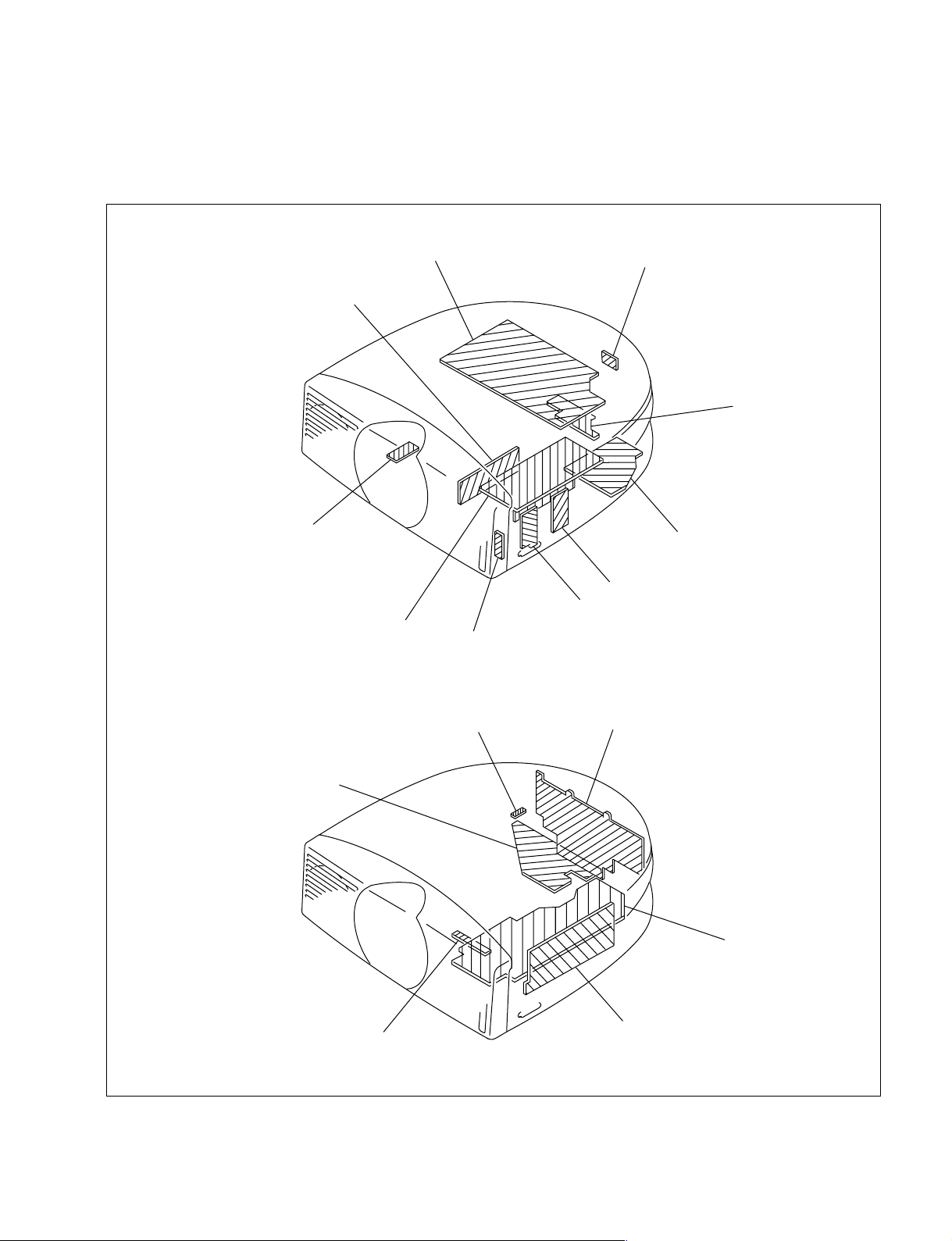
1-1. Board Layouts
Section 1
Service Informations
C
MD
U
Lamp power supply block
NR
QA
F
HB
HA
NF
QB
HC
L
B
G
MS
VPL-HS10
1-1
Page 10
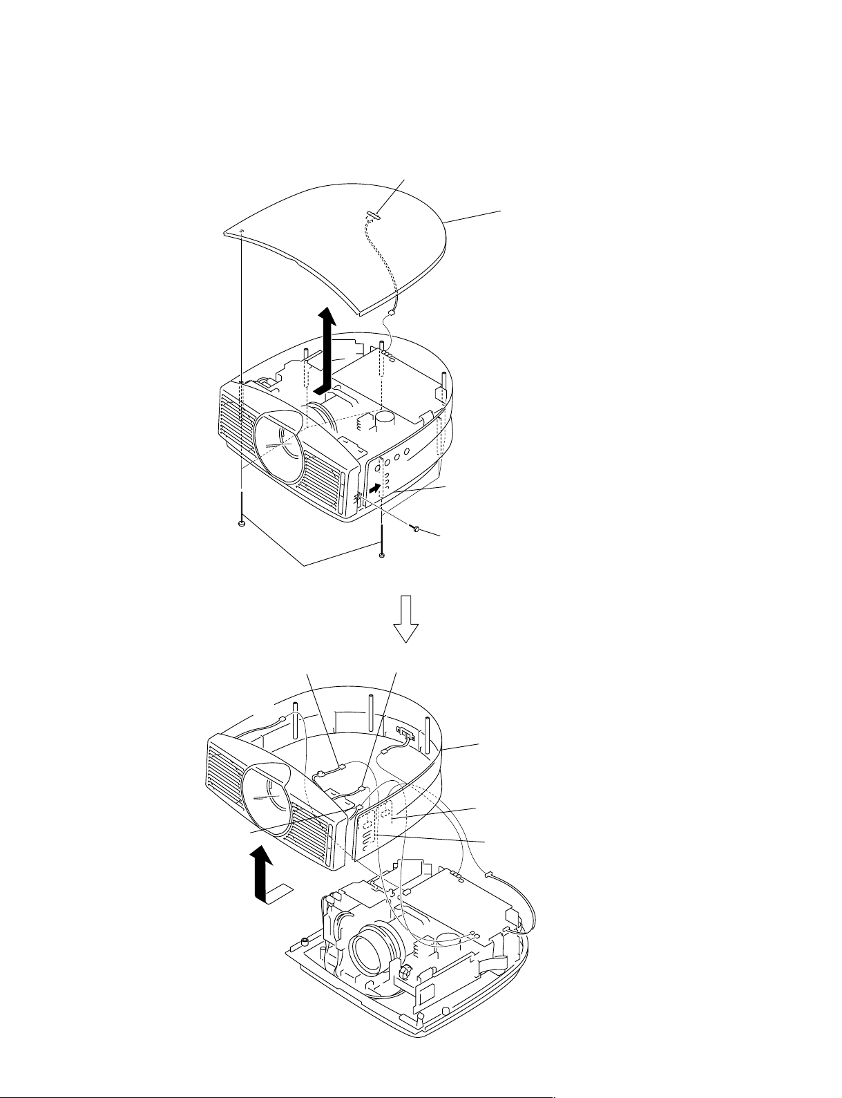
1-2. Disassembly
1-2-1. Front Panel Assy and Side Cover Assy Removal
L board
A
CN604
C board
2 Remove the top cover assy
in the direction of the arrow A.
CN610 (From DC fan)
CN611 (From DC fan)
CN602 (From NF board)
1 Six shafts
C
B
CN63 (From HC board)
CN603
3 Remove only one side of the side cover assy
in the direction of the arrow mark B.
(Do not give excessive force. Be careful not to break.)
4 Screw
(+B 3x6)
5 Remove the front panel assy, side cover assy
in the direction of the arrow C.
HB board
HA board
CN62
1-2
C board
VPL-HS10
Page 11
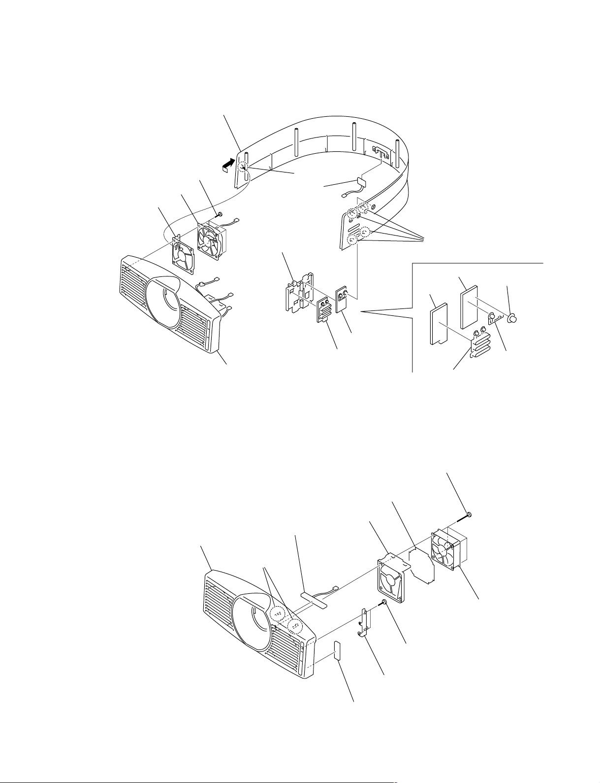
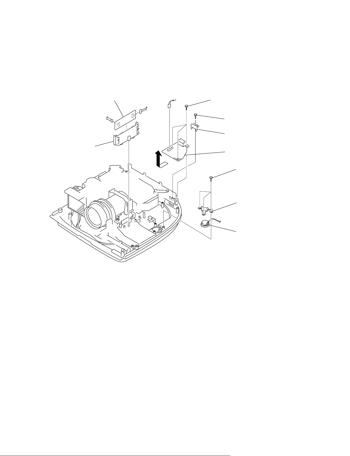
1-2-2. HA, HB and NR Boards Removal
1
4 Remove the side cover assy
in the direction of the arrow.
1 Four screws
(+PSW 3x10)
2 DC fan
3 Fan holder
Claw
6 NR board
7 H holder
5 Front panel assy
1-2-3. HC, NF Boards and DC Fan Removal
9 Front panel assy
8 HC board
8 HB board
9 HA board
3 Guard
2 Fan bracket
Four claws
HB board
HA board
!/ HA button
Four screws
(+PSW 3x30)
!= HB2 button
!- HB1 button
VPL-HS10
Two claws
4 DC fan
5 T wo screws
(+B 3x6)
6 FR holder
7 NF board
1-3
Page 12
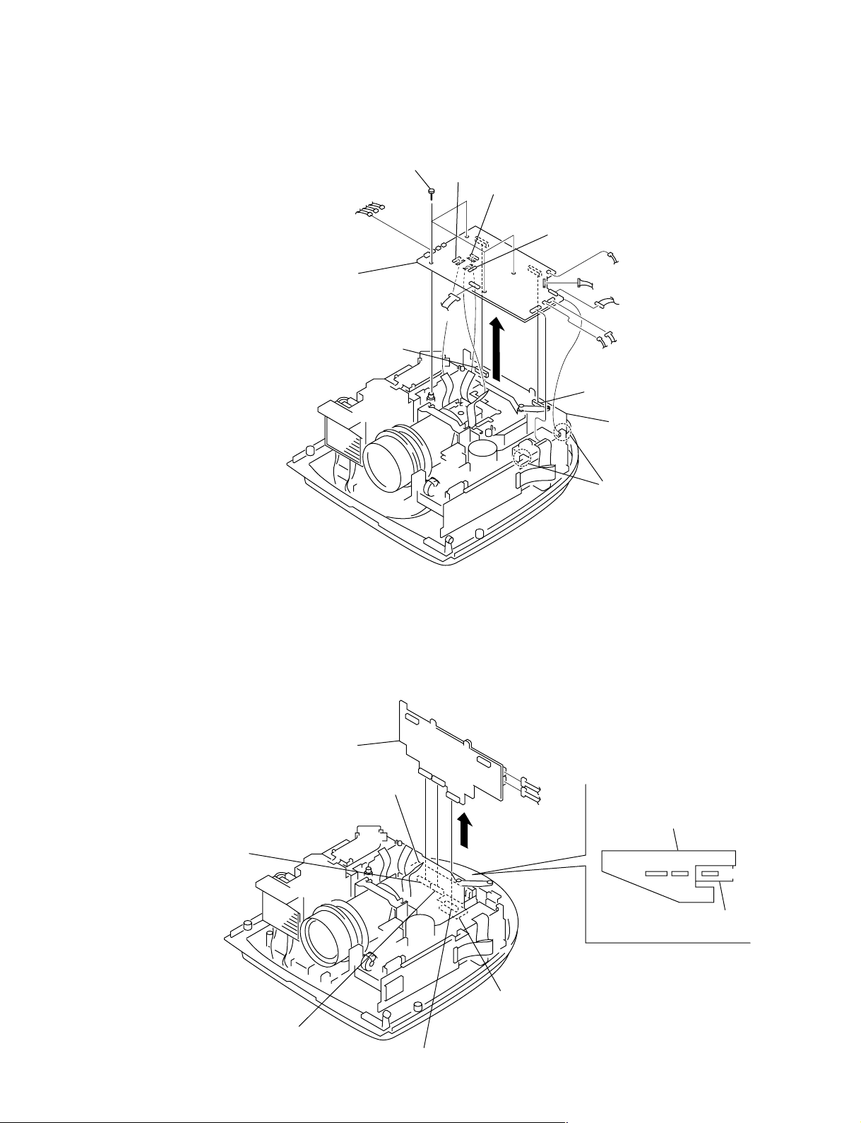
1-2-4. C Board Removal
1 Four screws
(+PSW 3 x12)
CN612
CN608
CN609
CN860
CN820
CN770
2 C board
CN112 (board to board)
1-2-5. B Board Removal
To remove the B board, remove the C board beforehand.
CN600
CN304
CN606
CN605
CN607
CN601
CN201
CN111 (board to board)
B board
Two claws
1-4
CN103 (board to board)
CN102 (board to board)
B board
QB board
CN902 (board to board)
CN105
CN106
QA board
B board
CN103
CN102
CN902
QA board
VPL-HS10
Page 13
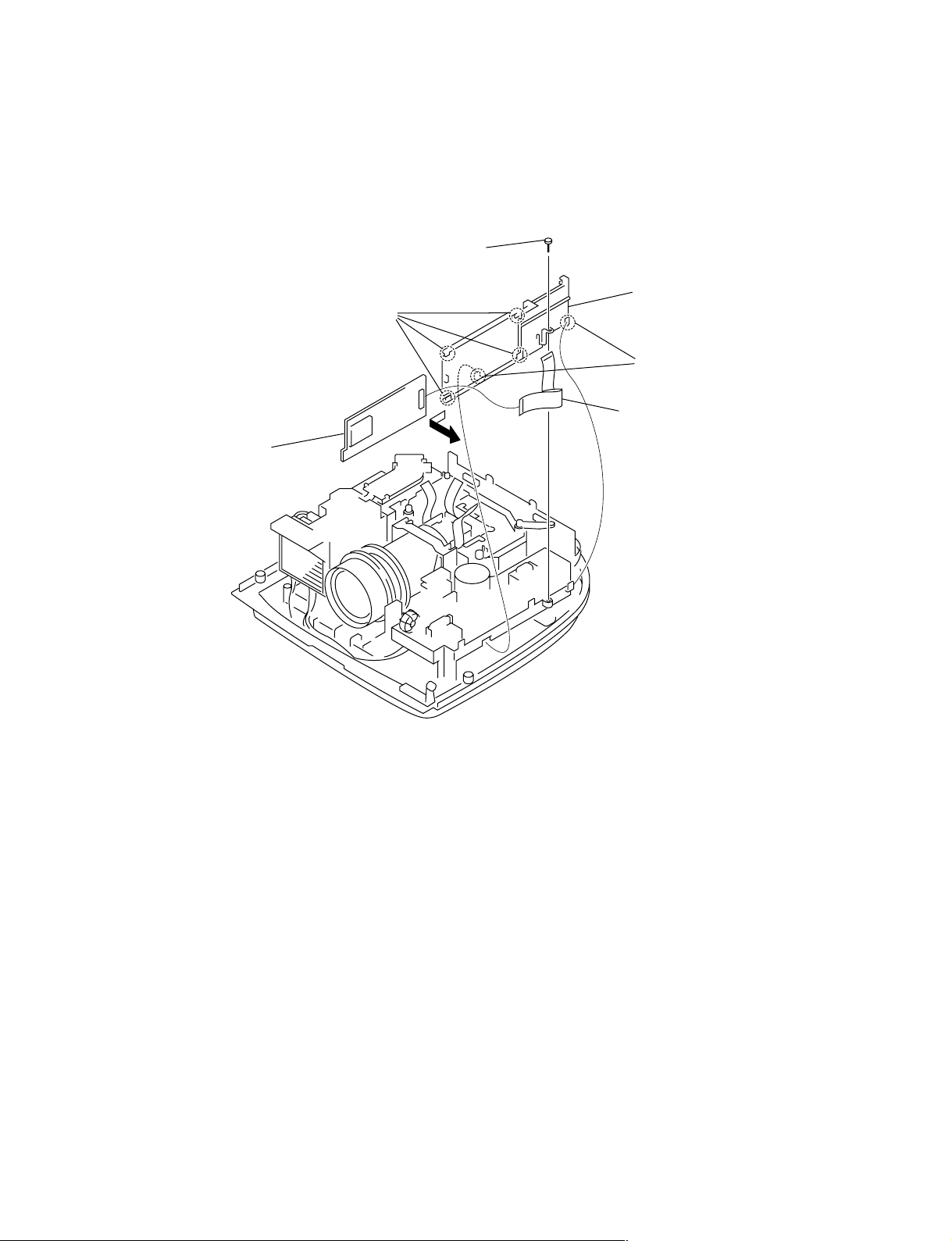
1-2-6. MS Board Removal
To remove the MS board, remove the C board beforehand.
2
screw
(+B 3x6)
Four claws
4
MS board
CN1001
3
Remove the MS bracket
in the direction of the arrow.
Two claws
1
Flat connector assy (50P)
VPL-HS10
1-5
Page 14
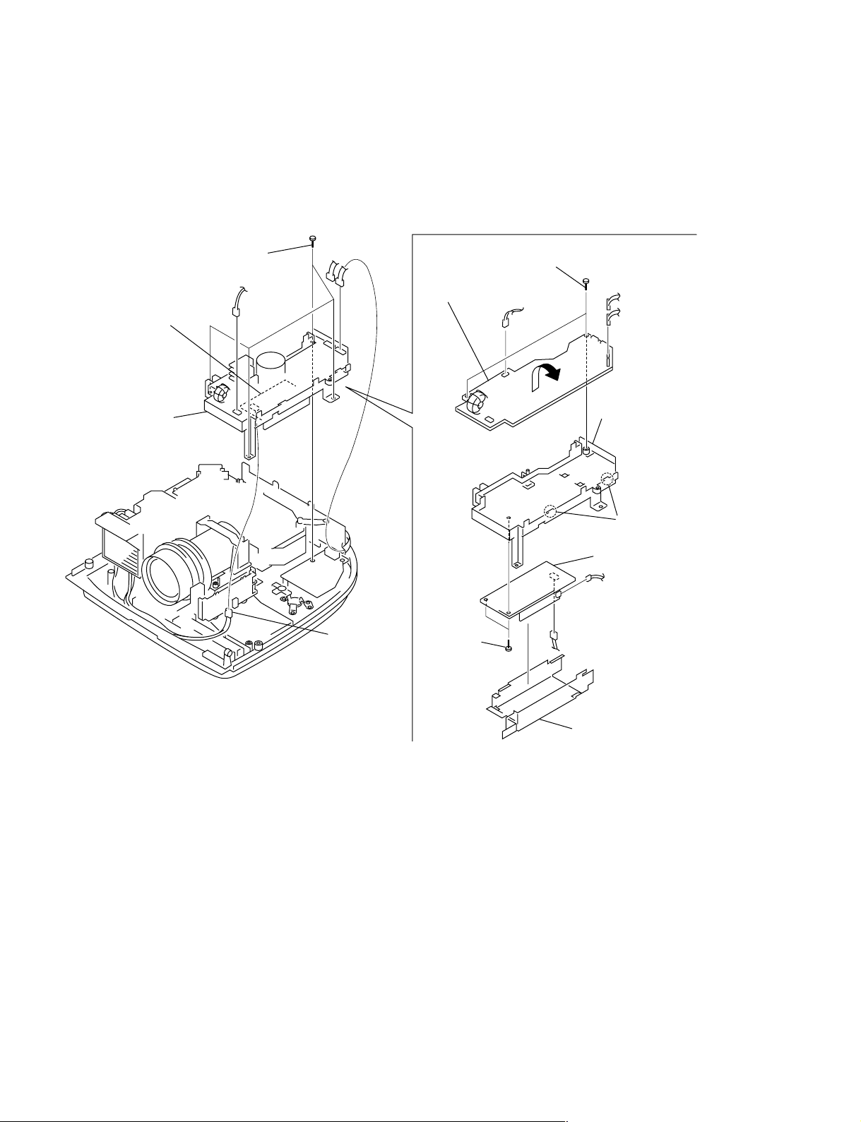
1-2-7. G Board and Lamp Power Supply Block Removal
To remove the G board and lamp power supply block, remove the C board, MS board beforehand.
Lamp power supply block
2
Power block assy
1 Four screws
(+B 3x6)
CN600
CN703
CN702
X3
3
Two screws
(+B 3x6)
4
Remove the G board
in the direction of the arrow.
CN601
6
Two screws
(+B 3x6)
X1
CN706
CN705
8
Power bracket
Two claws
7 Lamp
power supply block
1-6
5 G
bracket cover
VPL-HS10
Page 15
1-2-8. MD, F Boards and Speaker Removal
To remove the MD, F boards and speaker, remove the C board, MS bracket and power block assy beforehand.
1
MD bracket
CN802
2
MD board
CN801
CN502
5
Three screws
(+B 3x6)
3
4
6
Screw
(+B 3x6)
AC holder
F board
7
Three screws
(+B 3x6)
8
Speaker spring assy
9
Speaker
VPL-HS10
1-7
Page 16
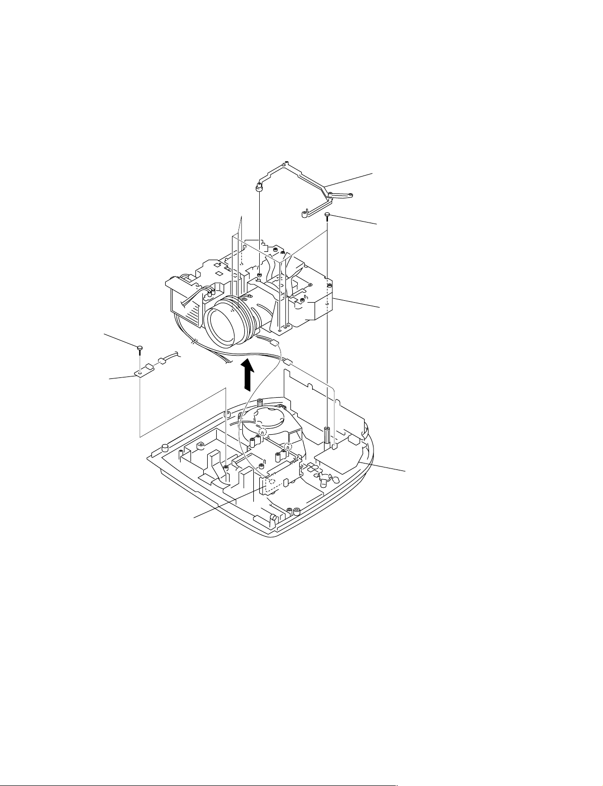
1-2-9. Optics Block Assy and U Board Removal
To remove the Optics block assy and U board, remove the C board, MS bracket and power block assy
beforehand.
1
C holder
2
Six screws
(+B 3x12)
3
Optics block assy
4
Screw
(+B 3x6)
CN802
5
CN41
CN502
U board
F board
MD board
1-8
VPL-HS10
Page 17
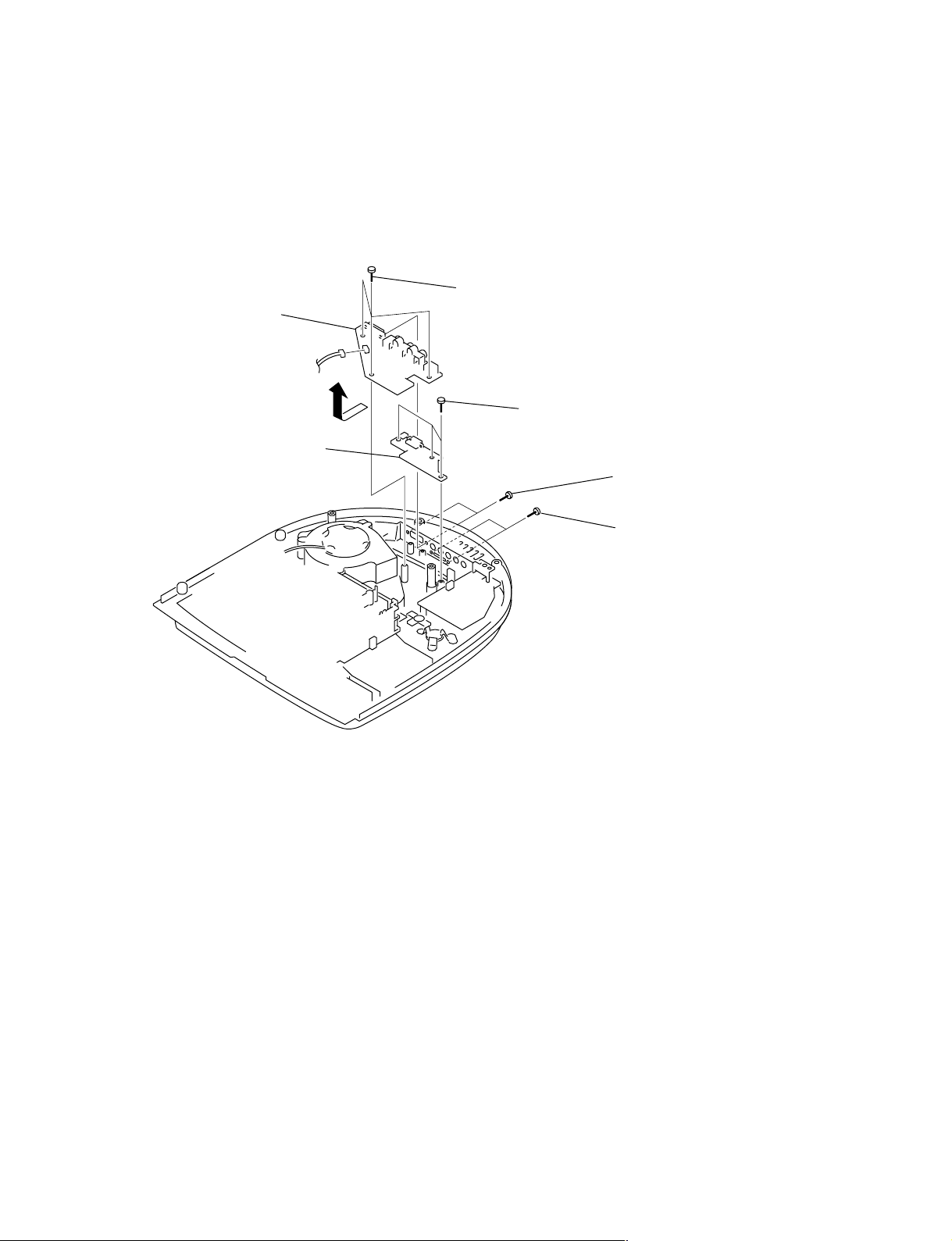
1-2-10. QA and QB Boards Removal
To remove the QA and QB boards, remove the C board, MS bracket, power block assy and Optics block
assy beforehand.
1
Three screws
3 QB board
CN101
6 QA board
(+B 3x6)
4
Three screws
(+B 3x6)
2
Two screws
5
Two screws
(+M 1.6x5)
VPL-HS10
1-9
Page 18
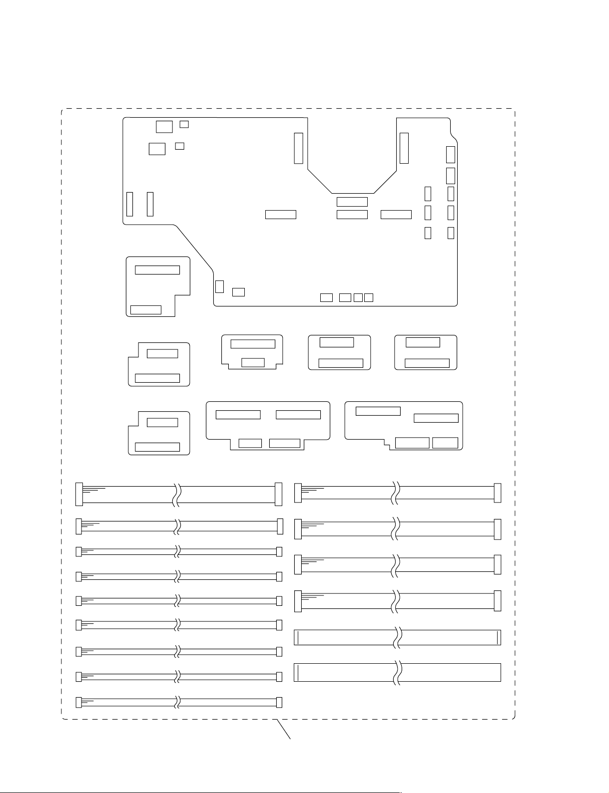
1-2-11. Extension Board and EXtension Connectors
X1 board
X4 board
X3 board
X3 board
SR connector assy (12P)
SR connector assy (5P)
SR connector assy (3P)
Two PH connectors assy (3P)
ZH connector assy A (3P)
ZH connector assy (4P)
ZH connector assy B (3P)
SR connector assy (2P)
X5 board
X7 board X6 board
X2 board X2 board
ZH connector assy (7P)
ZH connector assy (8P)
ZH connector assy (9P)
ZH connector assy (10P)
Three flat connectors assy (32P)
Eight flat connectors assy (50P)
1-10
SR connector assy (4P)
X kit assy (A-1604-096-A)
VPL-HS10
Page 19
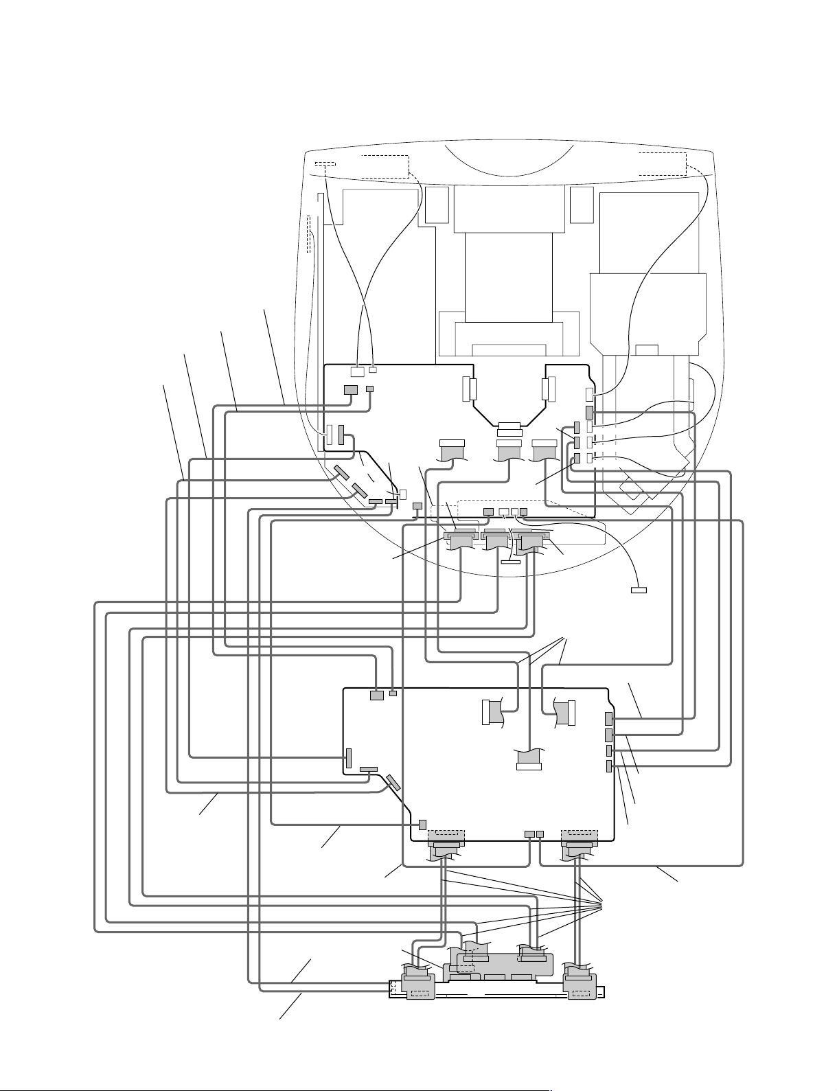
1-2-12. Extension Board and Extension Connectors Connection
y (9P)
PH connector assy (3P)
SR connector assy (3P)
SR connector assy
(12P)
ZH connector assy
(10P)
HB
NF
CN610
CN110
CN601
CN101
CN705
DC fan
G
CN602
CN102
CN703
CN706
CN702
CN106
X4
X1
QA
CN606
CN770
CN820
CN771
CN821
CN902
CN603
CN103 CN104
CN102
NR
CN112
CN604
CN108
CN861
CN860
CN109
CN103
DC fan
CN611
CN111
CN609
CN608
CN612
QB
X6
ZH connector assy
(7P)
ZH connector ass
CN610
CN601
CN607
SR connector assy (5P)
SSR connector assy (4P)
ZH connector assy (8P)
CN106
CN105
CN602
CN605
X5
CN32
CN606
CN22
CN33
CN111
X3
CN52
CN770
C
CN501
CN23
CN603
CN73
CN75
X7
CN108CN107 CN110
B
CN820
CN72
Flat connector assy
(32P)
PH connector assy (3P)
CN860
CN611
CN609
CN608
CN612
X2X2
CN604
CN22
CN502
CN23
Flat connector assy
(50P)
CN32
CN33
CN112
X3
L
ZH connector assy A
(3P)
ZH connector assy (4P)
ZH connector assy B (3P)
SR connector assy (2P)
VPL-HS10
1-11
Page 20
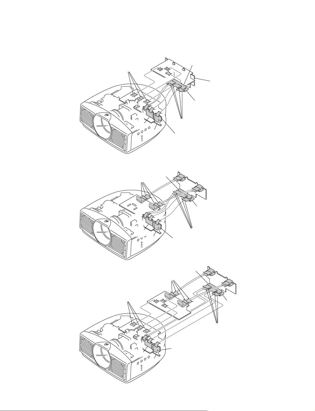
1-2-13. Connection Example
For C Board
Flat connector assy (32P)
X1
QB
X6
QA
X7
C
B
X5
Flat connector assy (50P)
X4
For B Board
For C and B Boards
Flat connector assy (50P)
X2
C
QB
Flat connector assy (50P)
Flat connector assy (32P)
X6
X2
QA
X2
X7
X3
X3
B
X5
Flat connector assy (50P)
X4
X7
C
X3
B
X3
X5
X2
1-12
X1
QB
X6
Flat connector assy (50P)
X4
QA
VPL-HS10
Page 21
1-3. Service Knowhow
1-3-1. After Replacing the Prism Block
1. Perform Section “2-2. V COM Adjustment.”
2. Perform the Gamma data writing of the Prism Block.
3. Perform Section “2-4. White Balance Adjustment on
Servicing.”
1-3-2. After Replacing the Board
. Refer to the cross table shown on right.
. There are no need to perform the adjustment when the board
other than the B board or C board had been replaced.
1) When Replacing the B Board
When the data before replacement can be read properly
1. Make a note of the data before replacement. After
replacement, write the data into the new board with
service mode.
2. If the white balance is extremely deteriorated, perform
the white balance adjustment (Refer to Section 2-4.).
When the data before replacement cannot be read
1. Perform Section “2-2. V COM Adjustment.”
2. Perform Section “2-4. White Balance Adjustment on
Servicing.”
3. Perform Section “2-5. Tilt Adjustment.”
2) When Replacing the C Board
1. Before replacement, unsolder the IC705 from the
replaced C board and then mount it to the new board.
2. Perform Section “2-2. V COM Adjustment.”
3. If the white balance is extremely deteriorated, perform
the white balance adjustment (Refer to Section 2-4.).
4. Perform Section “2-5. Tilt Adjustment.”
3) When Replacing the Other Board
There are no need to perform the adjustment.
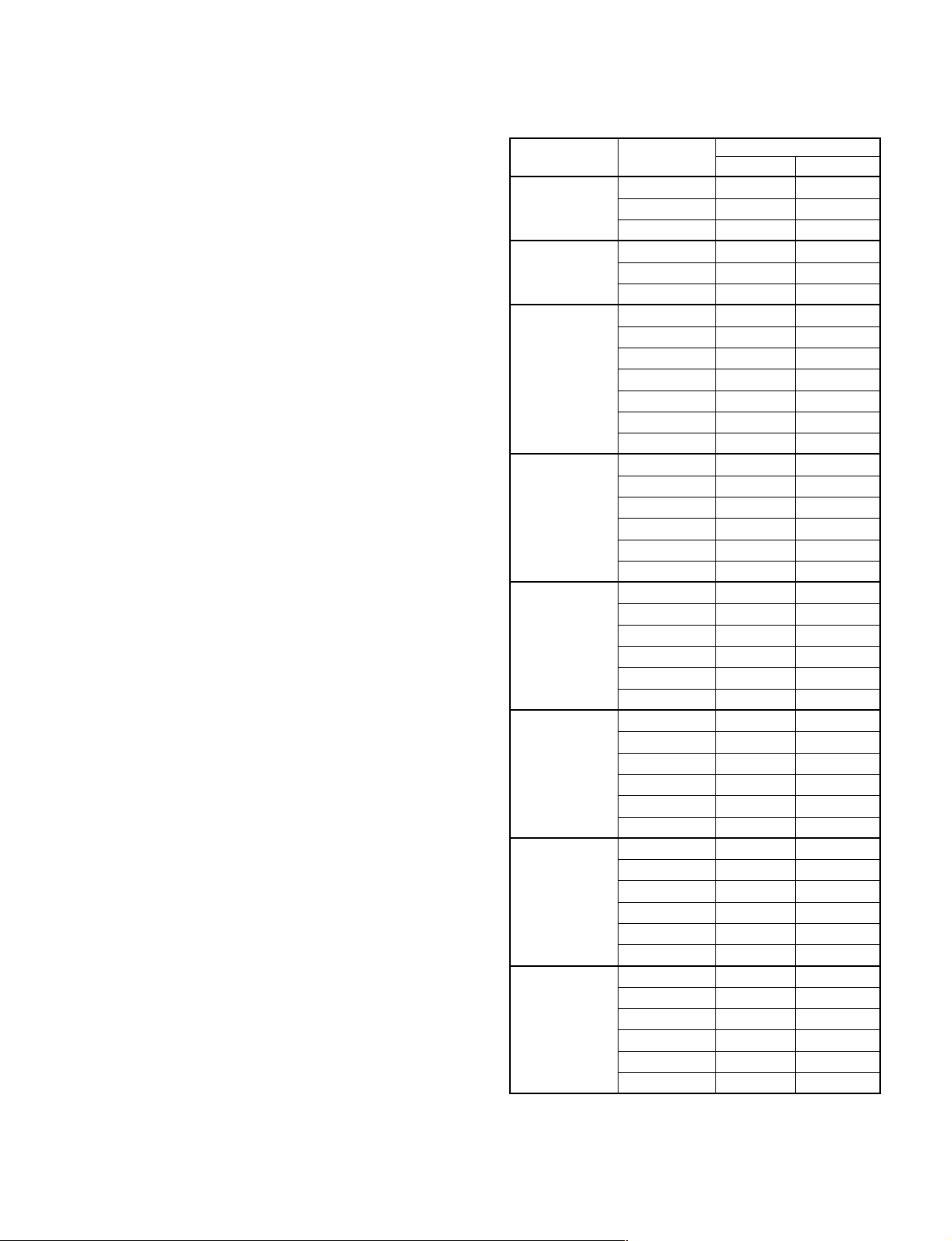
Cross Table of Board Replacement
Board Name
Device Name Item Name B C
OTHER TILT C0 * O
TILT C1 * O
TILT C2 * O
P.DRV VCOM (R) * O
VCOM (G) * O
VCOM (B) * O
W/B ADJUST
INPUT-A HIGH GAIN R * O
GAIN G * O
GAIN B * O
BIAS R * O
BIAS G * O
BIAS B * O
INPUT-A LOW GAIN R * O
GAIN G * O
GAIN B * O
BIAS R * O
BIAS G * O
BIAS B * O
INPUT-A HIGH GAIN R * O
GAIN G * O
GAIN B * O
BIAS R * O
BIAS G * O
BIAS B * O
INPUT-A MID GAIN R * O
GAIN G * O
GAIN B * O
BIAS R * O
BIAS G * O
BIAS B * O
VIDEO MID GAIN R * O
GAIN G * O
GAIN B * O
BIAS R * O
BIAS G * O
BIAS B * O
VIDEO LOW GAIN R * O
GAIN G * O
GAIN B * O
BIAS R * O
BIAS G * O
BIAS B * O
VPL-HS10
* : When down the data before replacement, and then
write in the data after the board replacement.
O : Need adjustment
Value: See description.
1-13
Page 22
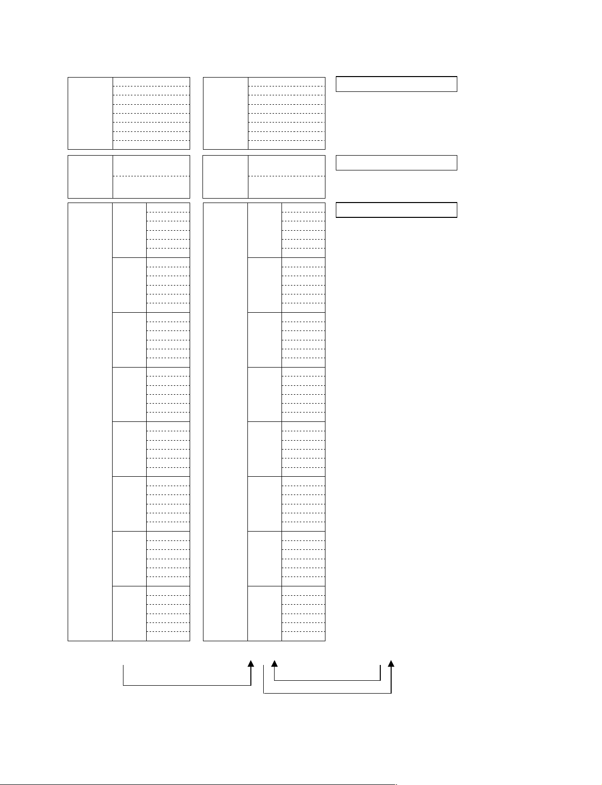
1-4. Memory
Memory structure consists of the following five memory
blocks.
1. Set memory
2. Status memory
3. Chroma memory
4. W/B memory
5. Channel memory
6. Image Flip memory
7. Picture memory
Gamma memory is actualized through Gamma mode
functions’offsetting the output values to the Contrast and
Brightness devices.
When the power plug is connected to the power line
(Standby status), all data inside the internal ROM are
written into the NVM (Nonvolatile Memory). When the
power is turned to on, required data for the current picture,
such as status memory data, etc., are selected, and they are
written into the internal RAM.
When adjustment is carried out, adjustment data are
CPU internal ROM : 384 kbyte Flash Memory
CPU internal ROM : 16 kbyte
External NVM memory : 8 kbyte EEPROM
written into the NVM automatically (items on the user
mode) or by the trigger of memory operation (items on the
service mode and special service mode), then stored them.
Adjustable items (W/B and Device Adjust) of the service
mode and special service mode are memorized into the
NVM by the memory operation. At the same time, the
factory preset (adjusted) data are all eliminated from the
memory.
Set Memory Set Memory Set Memory
Status
Memory
Chroma
Memory
W/B
Memory
No.01
No.02
No.03
No.04
...
No.99
NT358/443/BW60
PAL/PAL-M/N/
SECAM/BW50
15k RGB
Component (15k)
Two times speed
Component
HDTV (YPbPr)
HDTV (GBR)
(Include two times speed)
Computer
Others
HIGH
MIDDLE
LOW
HIGH
MIDDLE
LOW
Status
Memory
Chroma
Memory
W/B
Memory
No.01
No.02
No.03
Input-A
Preset
User
Component
Preset
User
MS
NT358/443/BW60
PAL/PAL-M/N/
SECAM/BW50
Input-A
Digital
Digital
No.04
...
No.99
No.101
...
No.120
No.03
No.04
...
No.99
No.03
No.04
...
No.99
No.121
...
No.140
No.53
...
No.69
15k RGB
Component (15k)
Two times speed
Component
HDTV (YPbPr)
HDTV (GBR)
(Include two times speed)
Computer
Others
HIGH
MIDDLE
LOW
HIGH
MIDDLE
LOW
Status Memory
Chroma Memory
W/B
Memory
HIGH
MIDDLE
LOW
1-14
VPL-HS10
Page 23
Channel
Memory
Image Flip
Memory
Video
S Video
Input-A
Video 2
S Video 2
Component
Digital
MS
Turn over to the upper and
lower sides
No turn over to the upper
and lower sides
Channel
Memory
Image Flip
Memory
Video 1
S Video 1
Input-A
Video 2
S Video 2
Component
Digital
MS
Turn over to the upper and
lower sides
No turn over to the upper
and lower sides
Channel Memory
Image Flip Memory
Picture
Memory
Video 1
S Video 1
Input-A
Video 2
S Video 2
Component
Digital
MS
CPU ROM
Dynamic
Standard
Cinema
User1
User2
User3
Dynamic
Standard
Cinema
User1
User2
User3
Dynamic
Standard
Cinema
User1
User2
User3
Dynamic
Standard
Cinema
User1
User2
User3
Dynamic
Standard
Cinema
User1
User2
User3
Dynamic
Standard
Cinema
User1
User2
User3
Dynamic
Standard
Cinema
User1
User2
User3
Dynamic
Standard
Cinema
User1
User2
User3
Initialize
Picture
Memory
Video 1
S Video 1
Input-A
Video 2
S Video 2
Component
Digital
MS
External NVM
Dynamic
Standard
Cinema
User1
User2
User3
Dynamic
Standard
Cinema
User1
User2
User3
Dynamic
Standard
Cinema
User1
User2
User3
Dynamic
Standard
Cinema
User1
User2
User3
Dynamic
Standard
Cinema
User1
User2
User3
Dynamic
Standard
Cinema
User1
User2
User3
Dynamic
Standard
Cinema
User1
User2
User3
Dynamic
Standard
Cinema
User1
User2
User3
Picture Memory
Memory
Active memory copy
CPU RAM
VPL-HS10
1-15
Page 24

1-5. Warning on Power Connection
Use a propre power cord for your local power supply.
The United States, Continental UK Australia Japan
Canada Europe
Plug type YP-11 YP-21 SP-61 B8 YP-13
Female end YC-13L YC-13L YC-13L C7-2 YC-13L
Cord type SPT-2 H03VVH2-F H03VVH2-F H03VVH2-F VCTFK
Rated Voltage & Current 10 A/125 V 2.5 A/250 V 2.5 A/250 V 2.5 A/250 V 7 A/250 V
Safety approval UL/CSA VDE BS SAA DENANHO
Cord length (max.) 4.5 m – – – –
1-16
VPL-HS10
Page 25

Section 2
Electrical Adjustments
2-1. Preparations
2-1-1. Equipment Required
. Oscilloscope
Tektronix 2465 or equivalent
(bandwidth: 350 MHz or more)
. NTSC, PAL, SECAM component signal generator
T ektronix TG2000 + AVG1 (optional module) + AWVG1
(optional module) or equivalent
. VG (Programmable video signal generator)
VG814 or equivalent
. Digital voltmeter
Advantest TR6845 or equivalent
. Luminance meter
. Chrominance difference gauge
n
Perform the following adjustments at least 5 minutes after
turning on the power.
2-2. V COM Adjustment
1. Input the green-only XGA 1 Lime ON/OFF signal to
INPUT-A, and set the CONTRAST to 70.
2. Set the screen to G VCOM adjustment of “Device
Adjust.”
3. Adjust the G VCOM so that the flicker on the screen is
minimum.
4. Change the input signal to the red-only and blue-only
1 line ON/OFF signal respectively and adjust R
VCOM and B VCOM respectively so that the flicker
becomes minimum as described in step 3.
5. Save the value adjusted.
6. Set the “Image Flip” to either “V” or “HV”.
7. Input the R/G/B value adjusted as above step 5.
8. Save the value adjusted.
9. Set the “Image Flip” to “OFF”.
2-1-2. Factory Mode Setting
1. Make sure that the MENU is indicated.
2. Exit the menu.
3. Press the keys in the following order:
“ENTER” → “ENTER” → “LEFT” → “ENTER”
4. The message “Do you wish to enter into the
FACTORY MODE? Yes:↑ No:↓ ” will be displayed.
5. Select “Yes:↑”.
n
. When leaving the FACTORY MODE, perform item 3.
“Do you wish to return to the USER MODE? Yes:↑ No:↓
” will be displayed. Select “Yes:↑”.
. Cannot enter FACTORY MODE by MS channel.
VPL-HS10
2-1
Page 26
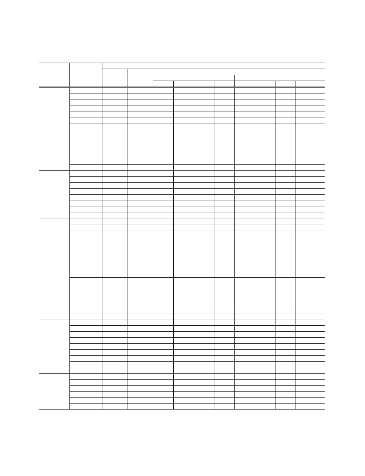
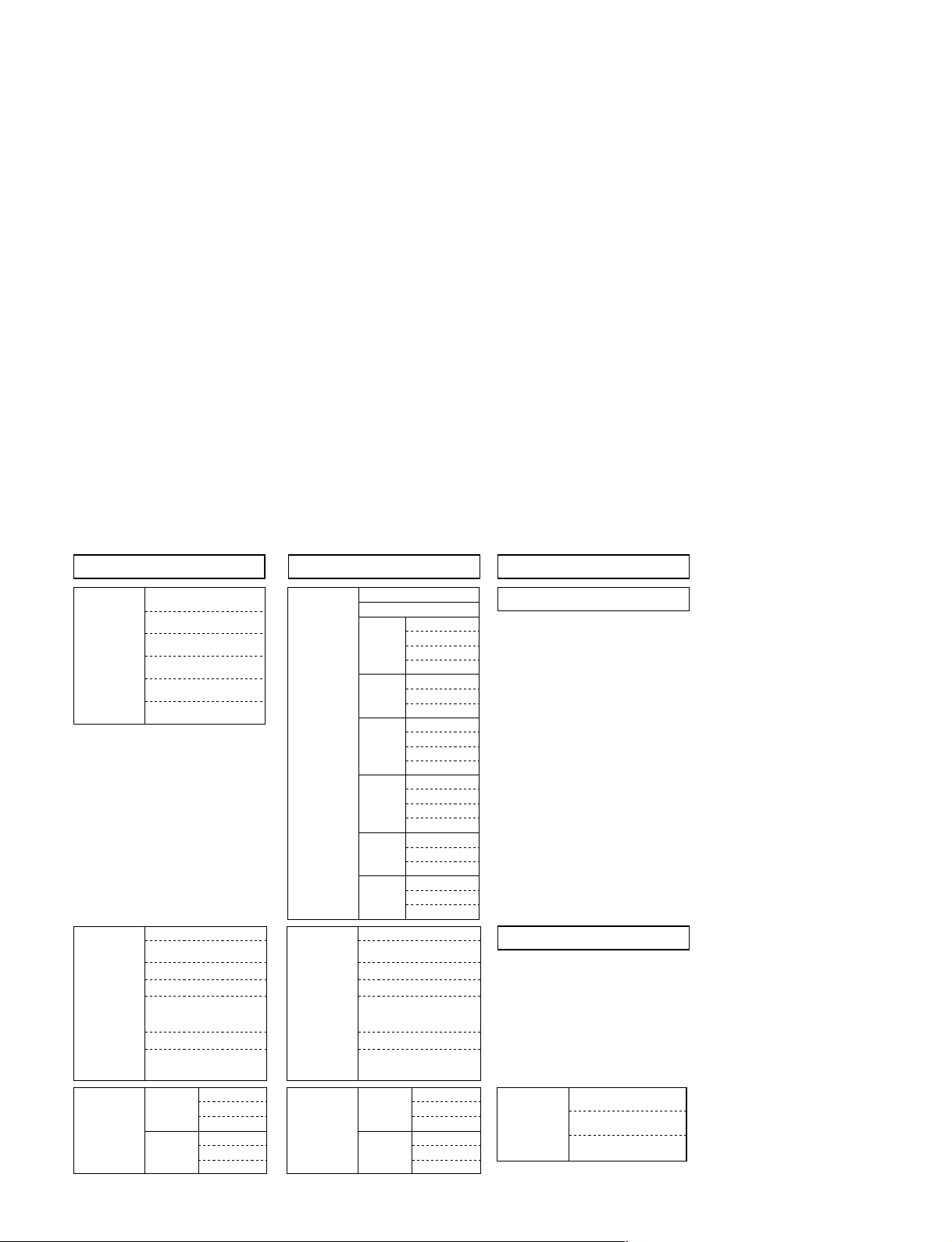
2-3. Adjustment Item Initialize Data
MenuTitle ItemName
PICTURE SETTING Picture Mode
INPUT SETTING
SET SETTING
MENU SETTING
INSTALL SETTING
INFORMATION
W/B SETTING
Adjust Picture...
Contrast
Brightness
Color
Hue
Sharpness
RGB Enhancer
Black Level Adj.
Gamma Mode
Color T emp.
DDE
Cinema Black
Volume
Adjust Signal...
Dot Phase
H Size
Shift
Wide Mode
V Position (Zoom)
V Position (Sub Title)
Title Area
Smart APA
Auto Input Search
Input-A Signal Sel.
Digital Signal Sel.
Color System
Power Saving
Illumination
Status
Languege
Menu Position
Menu Color
V Keystone
Manual...
Side Shot
Image Flip
Background
Test Pattern
fH
fV
(Memory No.)
(Resolution)
Lamp Timer
ROM Version
SC ROM Version
Operation Timer
Prev. Lamp Timer
Gain R
G
B
Bias R
G
B
Set Memory Status Memory
Dynamic
30
15 (*)
*
*
On
On
Component
Video GBR
Auto
Off
On
On
English
Center
Black
Auto
0
0
Off
Blue
On
Indication only
Indication only
Indication only
Indication only
Indication only
Indication only
Indication only
Indication only
Indication only
Memory Name
Video 1/S Video1/Video 2/S Video 2
Dynamic Standard Cinema User1/2/3
90
50
60
50
50
–
Low
–
Middle
Film
Off
Full
4
4
0
80
50
50
50
50
–
Low
–
High
Film
On
Full
4
4
0
80
50
50
50
50
Off
Low
Film
On
Full
80
50
50
50
–
–
4
4
0
50
–
Off
–
Low
Film
On
Full
4
4
0
Picture Memory
Dynamic Standard Cinema User1/2/3
90
50
60
50
50
20
Low
Graphics
Middle
Film
Off
Full
4
4
0
Input-A/Digital
80
50
50
50
50
20
Low
Graphics
High
Film
On
Full
4
4
0
80
50
50
50
50
20
Off
Graphics
Low
Film
On
Full
4
4
0
80
50
50
50
50
20
Off
Graphics
Low
Film
On
Full
4
4
0
* : “Dot Phase, H Size, Shift H/V and Picture Mode” in the “INPUT SETTING” menu have an initial value
respectively in accordance with the input signal (PRESET MEMORY No.).
Note : There are nonadjustable items in accordance with the input signal.
2-2
VPL-HS10
Page 27
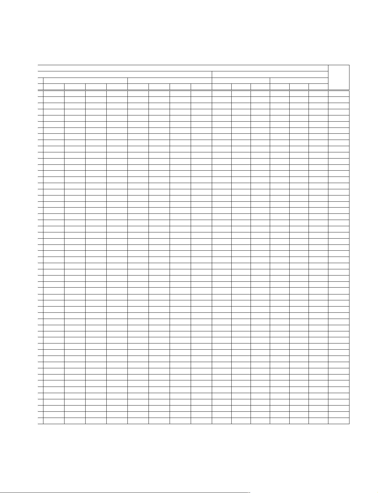
Picture Memory
Memory Name
Component
Dynamic Standard Cinema User1/2/3MSDynamic Standard Cinema User1/2/3
Video
High Middle Low
W/B Memory
Remarks
Computer
High Middle Low
90
50
60
50
50
–
Low
–
Middle
Film
Off
Full
4
4
0
80
50
50
50
50
Off
Low
Film
On
Full
80
50
50
50
–
–
4
4
0
50
–
Off
–
Low
Film
On
Full
4
4
0
80
50
50
50
50
–
Off
–
Low
Film
On
Full
4
4
0
90
50
60
––––
––––
20
–
Graphics Graphics Graphics Graphics
Middle
–
Off
–
–
–
–
80
50
50
20
–
High
–
On
–
–
–
–
80
50
50
20
Low
On
80
50
50
–
–
–
–
–
–
20
–
Low
–
On
–
–
–
–
VPL-HS10
182
182
182
85
85
85
182
150
160
85
85
85
182
150
160
85
85
85
160
160
160
85
85
85
160
140
150
85
85
85
160
140
150
85
85
85
2-3
Page 28
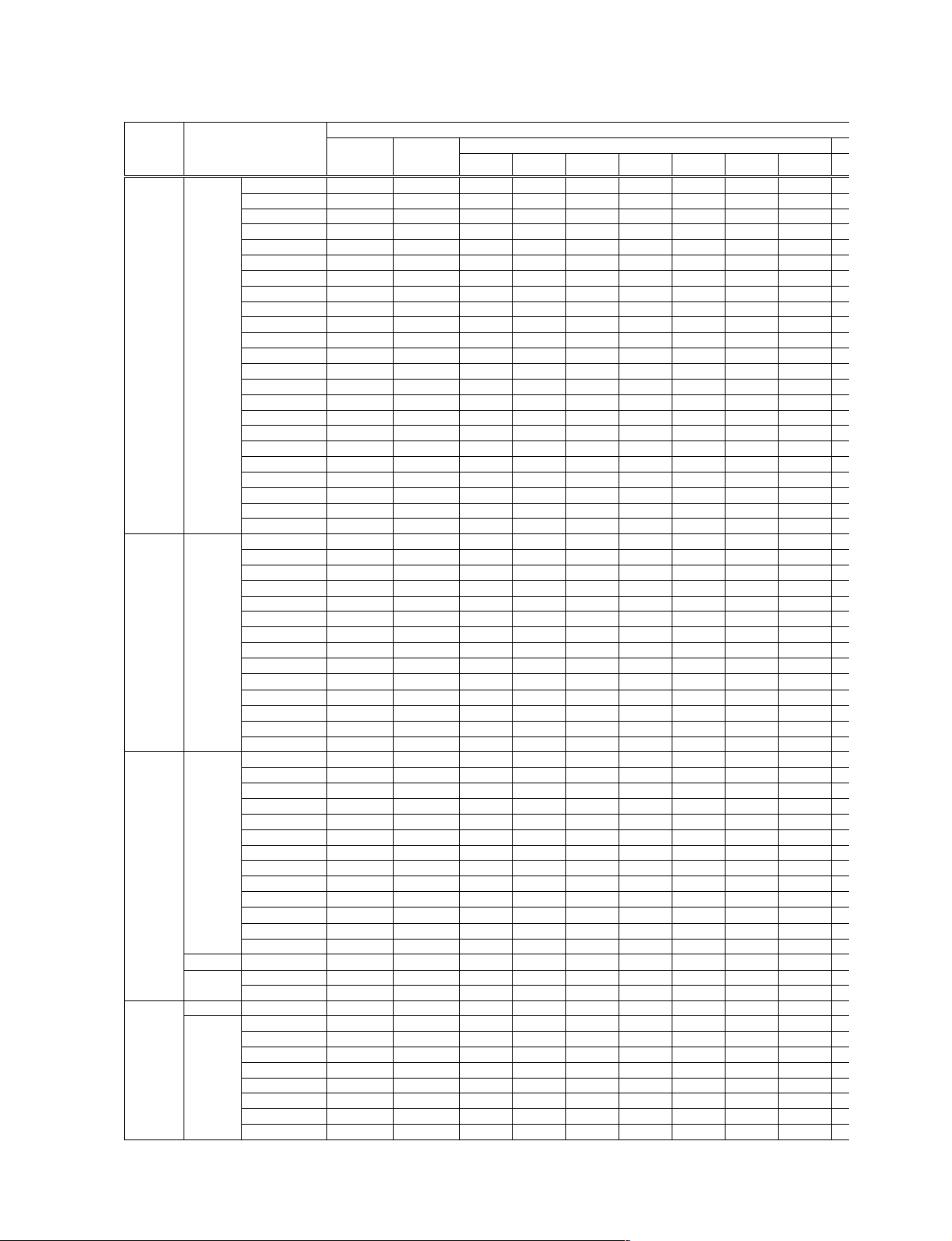
2-4
DeviceName ItemName
A/D Converter ADC/ Clamp Position
Chroma/D.Comb
Panel Driver P.Drv
Chroma/
Sample Hold/
Other/
3D GammaOther
Clamp Width
R Gain (Other)
R Gain (Component)
R Gain (VideoGBR)
G Gain (Other)
G Gain (Component)
G Gain (VideoGBR)
B Gain (Other)
B Gain (Component)
B Gain (VideoGBR)
R Offset (Other)
R Offset (Component)
R Offset (VideoGBR)
G Offset (Other)
G Offset (Component)
G Offset (VideoGBR)
B Offset (Other)
B Offset (Component)
B Offset (VideoGBR)
Sync Sep Th
Pre Coast
Post Coast
Ch1 Gain
Ch2 Gain
Video Brt
Video Cont
Sub Color
LCBW
Y-DeLay
Ch3 Gain
Ch4 Gain
YUV Brt
YUV Cont
AOSL
1E
1F
Offset R
Offset G
Offset B
V Common R
V Common G
V Common B
Psig 1
Psig 2
Signal Center
Gain R
Gain G
Gain B
DCFB Off
SH1
V Com Pth Enb
Installation
Sub Cont
Sub Brt
R Osd Lvl
G Osd Lvl
B Osd Lvl
Through
SW
APC Thres
APC Limit
Set Memory Status Memory Chroma Memory
32
*1
–
Indication only
Indication only
143
40
196
161
161
161
1
10
Adjustment is
impossible
0
0
0
31
31
31
0
1
25
32
*2
*2
2
8
NT358/NT443
/BW60
125
64
64
128
64
Memory Name
Pal/Pal-M/N/
Secam/BW50
124
73
64
128
64
Note : There are nonadjustable items in accordance with the input signal.
*1 : Depends on the color system and the input terminal.
*2 : Depend on the input signal.
15kRGB
128
64
64
119
67
Component
(15k)
128
64
64
119
67
Two times speed
Component
–
–
–
–
–
HDTV
(YPbPr)
–
–
–
–
–
HDTV(GBR)
Include two times speed
–
–
–
–
–
VPL-HS10
Page 29

Channel Memory
Memory Name
Video 1 S Video 1 Input-A Video 2 S Video 2 Component Digital MS
Image Flip Memory
Turn over to the upper
and lower sides
No turn over to the
upper and lower sides
Remarks
60
16
144
144
–
–
–
–
–
–
–
–
–
–
–
–
–
–
–
–
–
–
0
60
16
144
144
–
–
–
–
–
–
–
–
–
–
–
–
–
–
–
–
–
–
0
100
100
100
100
100
100
100
100
100
128
100
128
128
128
128
128
100
128
144
160
0
160
160
–
–
–
–
–
–
–
–
–
–
–
–
–
–
–
–
–
–
60
16
0
144
144
–
–
–
–
–
–
–
–
–
–
–
–
–
–
–
–
–
–
60
16
0
144
144
–
100
–
–
100
–
–
100
–
–
100
–
–
128
–
–
100
–
144
260
0
260
260
–
–
–
–
–
–
–
–
–
–
–
–
–
–
–
–
–
–
–
–
–
–
–
–
–
–
–
–
–
–
–
–
–
–
–
–
–
–
–
–
–
–
–
–
–
–
––
–
–
VPL-HS10
211
211
211
83
83
83
211
211
211
83
83
83
2-5
Page 30
DeviceName ItemName
Memory Name
Set Memory Status Memory Chroma Memory
V StartOther/Other
H Start (MSB)
H Start (LSB)
H Position
HST Position
HST Phase
Temp Lamp
Temp Panel
6
0
216
40
3
4
Adjustment is
impossible
Adjustment is
impossible
NT358/NT443
/BW60
Pal/Pal-M/N/
Secam/BW50
Fan1 H
Fan1 L
Fan2 H
Fan2 L
Fan3 H
Fan3 L
Synchronous
Tilt C0
Tilt C1
Tilt C2
X Tilt
Y Tilt
TL
TP
Highland Mode
Gamma
CTI T apIp/IP
CTI Shift
CTI Limit
CTI Gain
Sharp Limit
MD Thresh C
MD Thresh O
VS
Continue
Edit Detect
Indicator
Manual
Manual Pair
Manual State
Field Times
Noise Thresh
Disp Area
PULL Area T
PULL Area B
PULL Area L
PULL Area R
VS Limit
VS Core
Edge Det Less
X Only
Hysteresis
Hysteresis Data
Thresh Still Large
Thresh Still Med
Thresh Still Small
22 Pre Post Rate
22 Pre Post Thresh
Film Times 22
Sudare Rate 32Ip2/
Sudare Thresh 32
Sudare Rate 22
Sudare Thresh 22
1
Factory default
setting value
Factory default
setting value
Factory default
setting value
Indication only
Indication only
Indication only
Indication only
0
Factory default
setting value
3
1
128
0
255
8
16
1
1
0
0
0
0
0
2
4
0
71
203
165
765
64
4
1
0
1
2
2
3
4
15
2
3
4
64
4
40
Note : There are nonadjustable items in accordance with the input signal.
15kRGB
Component
(15k)
Two times speed
Component
HDTV
(YPbPr)
HDTV(GBR)
Include two times speed
2-6
VPL-HS10
Page 31

Channel Memory
Memory Name
Video 1 S Video 1 Input-A Video 2 S Video 2 Component Digital MS
Image Flip Memory
Turn over to the upper
and lower sides
No turn over to the
upper and lower sides
Remarks
Adjustment is
impossible
Adjustment is
impossible
Adjustment is
impossible
Adjustment is
impossible
Adjustment is
impossible
Adjustment is
impossible
Adjustment is
impossible
Adjustment is
impossible
Adjustment is
impossible
Adjustment is
impossible
Adjustment is
impossible
Adjustment is
impossible
VPL-HS10
2-7
Page 32

2-4. White Balance Adjustment on
Servicing
2-4-1. White Balance Adjustment
Input the 10 STEP signal to INPUT-A, and observe the
chromaticity of each luminance.
When varying the chromaticity of each luminance, perform
the following adjustments.
1) MID Mode of INPUT-A
1. Input the 100 IRE FLAT FIELD signal to INPUT-A.
2. Measure the chromaticity (x, y).
3. Input the 80 IRE FLAT FIELD signal to INPUT-A.
4. Adjust the chromaticity (x, y) to the values measured
in step 2, by the GAIN R and B of W/B MID mode.
5. Set the INPUT signal to the 30 IRE FLAT FIELD
signal.
6. Adjust the chromaticity (x, y) to the values measured
in step 2, by the BIAS R and B.
7. Repeat above steps 3 to 6 until the chromaticity
become the following values.
x ± 0.002, y ± 0.004 (The x and y are the values
measured in step 2.)
2) HIGH Mode of INPUT-A
3) LOW Mode of INPUT-A
1. Input the 80 IRE FLAT FIELD signal to INPUT-A.
2. Set the GAIN R that is equal to MID mode value. (Set
the GAIN R to the same as MID mode value.)
3. Set the BIAS R, G and B that are equal to MID mode
value. (Set the BIAS R, G and B to the same as MID
mode value).
4. Input the 30 IRE signal to INPUT-A.
5. Adjust the chromaticity (x at 0.313, y at 0.329) values
by the BIAS R and B of W/B LOW mode.
6. Input the 80 IRE signal to INPUT-A.
7. Adjust the chromaticity (x at 0.313, y at 0.329) values
by the GAIN G and B.
8. Repeat above steps 4 to 7 until the chromaticity
become the following values.
x: 0.313± 0.002, y: 0.329± 0.004
4) MID/HIGH/LOW Mode of VIDEO
1. Input the VIDEO signal of NTSC or PAL.
2. Set the BIAS R, G and B and GAIN R, G and B of
MID, HIGH and LOW mode of W/B that are equal to
the values of corresponding items in INPUT-A.
(Altogether 18 items)
3. Set the GAIN G only of MID mode of W/B value at
“_16” in INPUT-A.
1. Input the 80 IRE FLAT FIELD signal to INPUT-A.
2. Set the GAIN G to MID mode value at “_20” with the
HIGH mode of the W/B.
3. Set the BIAS R, G and B that are equal to MID mode
values. (Set the BIAS R, G and B to the same as MID
mode values.)
4. Input the 30 IRE signal to INPUT-A.
5. Adjust the chromaticity (x at 0.284, y at 0.298) values
by the BIAS R and B of W/B HIGH mode.
6. Input the 80 IRE signal to INPUT-A.
7. Adjust the chromaticity (x at 0.284, y at 0.298) values
by the GAIN R and B.
8. Repeat above steps 4. to 7. until the chromaticity
become the following values.
x: 0.284± 0.002, y: 0.298± 0.004
2-5. Tilt Adjustment
n
Do not put the unit upward and downward in the vertical
direction for more than ten seconds.
1. Set the Factory mode to “Device Adjust/OTHER”.
2. Set the adjuster in contracted position.
3. Then, enter the X TILT value to C0.
4. Set the unit upward in vertically.
5. Then, enter the X TILT value to C1.
6. Set the unit downward in vertically.
7. Then, enter the X TILT value to C2.
8. Save the each values of C0, C1 and C2 described in
step3, 5 and 7.
2-8
VPL-HS10
Page 33

Section 3
1
TOP VIEW
Semiconductors
IC
24LC21AT/SN
HN58X24256FPIZ
ICS332-SX1745
M24C02-WMN6T(A)
M24C64-WMN6T(B)
MAX1626ESA-TE2
MM1096AFF
MM1228XFBE
SN74LV08APWR
SN75157PS-ELL20
SN75157PS-ELL2000
ST24FC21M6TR
TA75W393FU
TA75W393FU-TE12R
TL431BCDR2
1
TOP VIEW
8PIN SOP
74VHC02MTCX
SN74LV00APWR
SN74LV04APWR
AK4352VT-E2
CY27027ZCT
LT1399CGN
SN74LV4052APWR
SN74LV4053APWR
TPA2000D1PW
1
TOP VIEW
16PIN SOP
BA00ASFP-E2
1
2
3
4
5
BA033FP-E2
BA05FP-E2
BA12FP-E2
CXD9671GG
INDEX
A
1
BOTTOM VIEW
176PIN BGA
HD64F2377VFQ33V
1
TOP VIEW
144PIN QFP
HY57V161610DTC-7TR
ISPLSI2032VE-110LT44A-51GB
1
TOP VIEW
44PIN QFP
L88M05T-FA-TL
LM1117MPX-1.8
NJM78M09DL1A(TE1)
1
2
3
LMC7101BIM5X
1
TOP VIEW
14PIN SOP
ADXL202JE-REEL
5
BOTTOM VIEW
1
TOP VIEW
1
2
3
BA6286N
17
3
1
MARKING SIDE VIEW
10PIN SIP
50PIN TSOP
IRMF-A0T-QTP
TK11900MTL
LP2985IM5X-3.3
S-80928ANMP-DDR-T2
SN74AHC1G00DCKR
TC4W53FU
TC4W53FU(TE12R)
TC7S66FU
TC7S66FU(TE85R)
TC7SET04FU(TE85R)
TC7SZ125FU(TE85R)
45
123
5PIN CHIP
VPL-HS10
3-1
Page 34

IC
1
A
BOTTOM VIEW
M52347FP-TE
SN74LV125APWR
SN74LV244APWR
SN74LV541APWR
1
TOP VIEW
20PIN SOP
M62392FP
1
TOP VIEW
24PIN SOP
MCZ3001D
1
TOP VIEW
18PIN DIP
MT48LC8M16A2TG-75-Y95WT
1
TOP VIEW
54PIN TSOP
MX29LV800TTC-70G-SX1745
48 25
PQ2TZ15U
1
PW265-10T
A
1
BOTTOM VIEW
256PIN BGA
SAA7118E/V1.518
156PIN BGA
5
TDA7309D013TR
1
TOP VIEW
20PIN DIP
ST72T631K4M1-201
MB93401A
A
1
BOTTOM VIEW
288PIN BGA
MB93491
1
TOP VIEW
176PIN QFP
124
TOP VIEW
48PIN TSOP
MZ1540
1
MARKING SIDE VIEW
PQ20VZ1U
RS-140-T
4
1
2
UPD64083GF-3BA
1
TOP VIEW
100PIN QFP
1
TOP VIEW
3
34PIN SOP
3-2
1:DC IN
5
2
2:ON/OFF CTL
3:DC OUT
4:DC OUT ADJ
4
5:GND
VPL-HS10
1
3
Page 35

Transistor, Diode
2SA1162-G
2SA1162-YG-TE85L
2SA1576A-T106-QR
2SC2712-YG
2SC2712-YG-TE85L
2SC4081-R
2SC4081T106R
DTA144EUA-T106
DTC144EKA
DTC144EKA-T146
DTC144EUA-T106
C
B
E
2SA1213Y-TE12L
B
C
E
HN1B01FU-TE85R
HN1C01FU-TE85R
HN1C03FU-TE85R
6
5
1
2
6
3
1
2
5
3
XP4501
4
3
2
1
4
5
3
2
1
1SS355TE-17
PC123GY2
UF4005PKG23
MA111-TX
UDZSTE-173.9B
4
CATHODE
3
4
1
4
ANODE
CATHODE
BZA456A
2
ANODE
RM11C
RM11C-V1
6
5
5
6
1
2
3
1
2
6
3
4
6
5
4
CATHODE
ANODE
2SK2876-01MR-F122
G
S
D
2SJ530S-TL
D
G
D
S
SI4425DY-T1
8
7
6
5
1
2
3
4
D
D
S
S
S
D
G
SSM6N15FU(TE85R)
4
5
3
2
1
4
5
3
2
1
D
6
6
D10SC6M
1
2
3
1
2
3
DAN202K
DAN202K-T-146
DAN202U
DAN202UT106
DAP202K
DAP202K-T-146
3
2
1
3
2
1
RD15ES-B3
RD15ES-T1B3
CATHODE
ANODE
RD13M-T1B
RD18M-T1B1
RD39M-T1B
RD7.5M-B2
RD7.5M-T1B
UZM13B
3
2
1
3
2
1
VPL-HS10
3-3
Page 36

Page 37

4-1. Notes on Repair Parts
1. Safety Related Components Warning
w
Components marked ! are critical to safe operation.
Therefore, specified parts should be used in the case of
replacement.
[WARNHINWEIS][WARNHINWEIS]
[WARNHINWEIS]
[WARNHINWEIS][WARNHINWEIS]
Les composants identifiés par la marque ! sont
critiques pour la sécurité.
Ne les remplacer que par une pièce portant le numéro
spécifié.
2. Standardization of Parts
Some repair parts supplied by Sony differ from those
used for the unit. These are because of parts commonality and improvement.
Parts List has the present standardized repair parts.
Section 4
Spare Parts
3. Stock of Parts
Parts marked with “o” at SP (Supply Code) column of
the Spare Parts list may not be stocked. Therefore, the
delivery date will be delayed.
Items with no part number and no description are not
stocked because they are seldom required for routine
service.
4. Units for Capacitors, Inductors and Resistors
The following units are assumed in Schematic Diagrams, Electrical Parts List and Exploded Views
unless otherwise specified.
Capacitors : µF
Inductors : µH
Resistors : Z
VPL-HS10
4-1
Page 38

Cover
4-2. Exploded Views
4-2-1. Cover
17
25
+BVTP 3x8
14
+PSW 3x10
10
3
+B 3x6
7
1
13
12
20
4
16
8
9
11
27
15
+PSW 3x30
23
6
21
+B 3x6
2
+B 3x6
26
19
5
24
22
4-2
18
VPL-HS10
Page 39

No. Part No. SP Description
1 A-1401-568-A s MOUNTED CIRCUIT BOARD, L
2 A-1401-570-A s MOUNTED CIRCUIT BOARD, NF
3 A-1401-571-A s MOUNTED CIRCUIT BOARD, NR
4 A-1401-578-A s MOUNTED CIRCUIT BOARD, HC
5 A-1401-579-A s MOUNTED CIRCUIT BOARD, HA
6 A-1401-580-A s MOUNTED CIRCUIT BOARD, HB
7
!
X-4041-160-1 s CABINET ASSY, TOP
8 X-4041-020-1 s HOLDER FILTER (B) ASSY
9 X-4041-021-1 s HOLDER, FILTER (A) ASSY
10 X-4041-023-1 s GUIDE LIGHT ASSY
11 X-4041-027-1 s HOLDER, FILTER ASSY
12
!
X-4041-028-1 s PANEL ASSY, FRONT
13
!
X-4041-030-1 s COVER ASSY, SIDE
14
!
1-763-422-11 s FAN, DC
15
!
1-763-874-11 s FAN, D.C.
16 4-091-802-01 o CUSHION, FAN
17 4-091-827-01 o HOLDER, HOOD
18 4-091-831-01 s SHAFT
19 4-091-840-01 o HOLDER (FR)
20 4-091-858-01 o BRACKET (PW), FAN
21 4-091-850-01 s BUTTON (HB1)
22 4-091-851-01 s BUTTON (HB2)
23 4-091-854-01 o HOLDER (H)
24 4-091-855-01 s BUTTON (HA)
25 4-091-856-01 o HOLDER (92), FAN
Cover
26 4-092-117-01 o GUARD
27 4-091-845-01 s FILTER, LENS (CINEMA FILTER)
7-682-547-04 s SCREW +B 3X6
7-685-646-79 s SCREW +BVTP 3X8
7-682-949-01 s SCREW +PSW 3X10
7-682-955-09 s SCREW +PSW 3X30
VPL-HS10
4-3
Page 40

Chassis
4-2-2. Chassis
+B 3x12
103
+B 3x6
104
+B 3x6
101
118
113
+B 3x6
109
+B 3x6
105
114
116
+B 3x6
112
+B 3x6
117
+B 3x6
+B 3x6
111
+B 3x6
+B 3x6
106
119
110
102
4-4
115
108
107
VPL-HS10
Page 41

No. Part No. SP Description
101 A-1300-767-A s MOUNTED CIRCUIT BOARD, MD
102 A-1300-769-A s MOUNTED CIRCUIT BOARD, MS
103 A-1300-770-A s MOUNTED CIRCUIT BOARD, B
104 A-1300-771-A s MOUNTED CIRCUIT BOARD, C
105 A-1300-772-A s MOUNTED CIRCUIT BOARD, G
106 A-1300-924-A s MOUNTED CIRCUIT BOARD, F
107 ! A-1603-999-A s SPEAKER ASSY
108 X-4039-453-1 o SPRING ASSY, SPEAKER
109 ! 1-468-719-11 s LAMP POWER SUPPLY BLOCK
110 1-900-270-03 o FLAT CONNECTOR ASSY 50P
111 4-085-052-01 o HOLDER (AC)
112 4-091-803-01 o CUSHION, G BRACKET
113 4-091-810-01 o COVER, G BRACKET
114 ! 4-091-865-01 o BRACKET, POWER
115 4-091-826-01 o HOLDER (FB)
116 4-091-834-01 o PLATE, EARTH
117 4-091-838-01 s SCREW M 5X5, SPECIAL
118 4-091-847-01 o BRACKET (MD)
119 4-091-857-01 o BRACKET (MS)
7-682-547-04 s SCREW +B 3X6
7-682-550-04 s SCREW +B 3X12
Chassis
VPL-HS10
4-5
Page 42

Base
4-2-3. Base
216
225
214
207
220
+B 3x6
+B 3x6
+PSW 3x35
+B 3x6
213
212
+BVTP 3x10
+B 3x12
209
+B 3x6
+B 3x20
+PS 3x10
208
222
+B 3x6
+B 3x12
202
+B 3x6
215
+B 3x6
218
205
+B 3x6
221
+B 3x6
+B 3x6
203
224
+B 3x6
219
210
218
+B 3x6
201
211
206
217
204
4-6
223
VPL-HS10
Page 43

No. Part No. SP Description
201 A-1300-768-A s MOUNTED CIRCUIT BOARD, QA
202 A-1300-773-A s MOUNTED CIRCUIT BOARD, QB
203 A-1401-572-A s MOUNTED CIRCUIT BOARD, U
204 ! X-4041-159-1 s COVER ASSY, FILTER
205 ! X-4041-024-1 s DOOR ASSY, LAMP
206 ! X-4041-029-1 s BASE ASSY
207 ! 1-763-238-11 s FAN, DC
208 ! 1-763-695-11 s FAN, DC
209 1-900-270-16 o CONNECTOR ASSY, LAMP POWER
210 4-084-430-01 o BRACKET, UNIT
211 4-085-075-01 s SCREW M 1.6X5, SPECIAL HEAD
212 4-091-805-01 o BRACKET FAN (R)
213 4-091-806-01 o PLATE, LIGHT INTERSEPTION
214 4-091-812-01 o DUCT LAMP (LOW)
215 4-091-816-01 o DUCT IN (LOW)
216 4-091-817-01 o DUCT IN (UP)
217 4-091-835-01 o FOOT, REAR
218 4-091-838-01 s SCREW M 5X5, SPECIAL
219 4-091-841-01 s BUTTON, ADJUSTOR
220 4-091-842-01 o PACKING (FAN)
221 4-091-853-01 o UNIT, BUTTON
222 4-091-859-01 o HOLDER (C)
223 4-091-860-01 s ADJUSTOR
224 4-091-861-01 o BASE, UNIT
225 4-091-811-01 o DUCT LAMP (UP)
Base
7-682-547-04 s SCREW +B 3X6
7-682-550-04 s SCREW +B 3X12
7-682-553-09 s SCREW +B 3X20
7-682-649-09 s SCREW +PS 3X10
7-682-956-09 s SCREW +PSW 3X35
7-685-647-79 s SCREW +BVTP 3X10
VPL-HS10
4-7
Page 44

Optics
4-2-4. Optics
310
b
302
311
312
318
322
328
g
d
315
316
c
309
313
317
315
d
326
314
321
320
325
g
c
+B 3x3
303
a
+B 3x3
+BVTP 3x6
307
+BVTP 3x10
305
304
a
b
327
324
326
f
319
301
323
308
4-8
305
+K 3x6
306
VPL-HS10
Page 45

No. Part No. SP Description
301 A-1604-059-A s PRISM BLOCK ASSY
302 A-1604-079-A s OPTICAL BLOCK (G) ASSY
303 ! 1-576-523-11 s THERMOSTAT
304 ! 9-885-019-00 s FAN
305 3-715-526-01 o WASHER (M3) (PLA)
306 4-086-247-01 s SCREW, STEP M3
307 4-091-814-01 s HOUSING, LAMP
308 9-885-029-43 s POLARIZER, R OUT
309 9-885-028-79 o EYE (A) ASSY, FLY
310 9-885-028-80 o EYE (B),FLY
311 9-885-014-68 o PBS ASSY
312 9-885-014-69 o LENS, MAIN CONDENSER
313 9-885-014-70 o MIRROR, ALL REFLECTION (A)
314 9-885-028-81 o BDM
315 9-885-014-72 o FILTER, UV ABSORPTION
316 9-885-014-73 o MIRROR, ALL REFLECTION (B)
317 9-885-028-82 o LENS, B-CH CONDENSER
318 9-885-029-40 s POLARIZER, B IN
319 9-885-029-41 s POLARIZER, B OUT
320 9-885-028-83 o GDM
321 9-885-028-84 o LENS, G-CH CONDENSER
322 9-885-028-85 s POLARIZER, G IN
323 9-885-028-86 s POLARIZER, G OUT
324 9-885-014-81 o LENS (A), RELAY
325 9-885-014-82 o MIRROR, ALL REFLECTION (C)
Optics
326 9-885-014-83 o LENS (B), RELAY
327 9-885-028-87 o RDF
328 9-885-029-42 s POLARIZER, R IN
7-682-247-09 s SCREW +K 3X6
7-682-544-04 s SCREW +B 3X3
7-685-645-79 s SCREW +BVTP 3X6
7-685-647-79 s SCREW +BVTP 3X10
VPL-HS10
4-9
Page 46

4-3. Electrical Parts List
------B BOARD
------ Ref. No.
or Q'ty Part No. SP Description
(B BOARD)
Ref. No.
or Q'ty Part No. SP Description
1pc A-1300-770-A s MOUNTED CIRCUIT BOARD, B
C172 1-125-777-11 s CAPACITOR CERAMIC 0.1MF/10V
C173 1-125-777-11 s CAPACITOR CERAMIC 0.1MF/10V
C101 1-164-299-11 s CAPACITOR,CHIP CERAMIC 0.22MF
C102 1-164-299-11 s CAPACITOR,CHIP CERAMIC 0.22MF
C103 1-164-156-11 s CAPACITOR,CERAMIC 0.1MF/25V F
C174 1-125-777-11 s CAPACITOR CERAMIC 0.1MF/10V
C175 1-125-777-11 s CAPACITOR CERAMIC 0.1MF/10V
C176 1-126-205-11 s CAPACITOR,ELECT 47M/6.3
C104 1-115-156-11 s CAPACITOR,CERAMIC 1MF/10V(1608
C105 1-125-777-11 s CAPACITOR CERAMIC 0.1MF/10V
C177 1-125-777-11 s CAPACITOR CERAMIC 0.1MF/10V
C178 1-125-777-11 s CAPACITOR CERAMIC 0.1MF/10V
C106 1-128-992-11 s CAPACITOR ELECT 47MF 25V
C107 1-117-681-11 s CAPACITOR, ELECT 100MF/16V
C108 1-128-992-11 s CAPACITOR ELECT 47MF 25V
C179 1-128-390-11 s CAPACITOR ELECT 220MF/6.3V
C180 1-164-860-11 s CAPACITOR,CHIP CERAMIC 27PF/16
C181 1-128-013-11 s CAPACITOR ERECT 1MF/50V
C109 1-117-681-11 s CAPACITOR, ELECT 100MF/16V
C111 1-164-943-11 s CAPACITOR,CHIP CERAMIC 0.01MF
C182 1-128-004-11 s CAPACITOR ELECT 10MF/16V(CHIP)
C183 1-164-854-11 s CAPACITOR CERAMIC 15PF/16V CH
C112 1-126-205-11 s CAPACITOR,ELECT 47M/6.3
C113 1-164-943-11 s CAPACITOR,CHIP CERAMIC 0.01MF
C114 1-126-205-11 s CAPACITOR,ELECT 47M/6.3
C184 1-164-854-11 s CAPACITOR CERAMIC 15PF/16V CH
C185 1-164-315-11 s CAPACITOR,CERAMIC 470PF/50V CH
C186 1-107-820-11 s CAPACITOR,CHIP CERAMIC 0.1MF F
C115 1-164-943-11 s CAPACITOR,CHIP CERAMIC 0.01MF
C116 1-126-205-11 s CAPACITOR,ELECT 47M/6.3
C187 1-128-013-11 s CAPACITOR ERECT 1MF/50V
C188 1-126-206-11 s CAPACITOR, ELECT 100MF/6.3V
C117 1-164-943-11 s CAPACITOR,CHIP CERAMIC 0.01MF
C118 1-126-205-11 s CAPACITOR,ELECT 47M/6.3
C119 1-164-943-11 s CAPACITOR,CHIP CERAMIC 0.01MF
C192 1-164-854-11 s CAPACITOR CERAMIC 15PF/16V CH
C193 1-115-339-11 s CAPACITOR,CERAMIC 0.1MF/50V
C194 1-128-004-11 s CAPACITOR ELECT 10MF/16V(CHIP)
C120 1-126-205-11 s CAPACITOR,ELECT 47M/6.3
C121 1-164-943-11 s CAPACITOR,CHIP CERAMIC 0.01MF
C195 1-164-505-11 s CAPACITOR,CHIP CERAMIC 2.2MF
C196 1-126-204-11 s CAPACITOR, ELECT 47MF/16V(CHIP
C122 1-126-205-11 s CAPACITOR,ELECT 47M/6.3
C135 1-126-206-11 s CAPACITOR, ELECT 100MF/6.3V
C136 1-126-206-11 s CAPACITOR, ELECT 100MF/6.3V
C197 1-164-854-11 s CAPACITOR CERAMIC 15PF/16V CH
C198 1-164-156-11 s CAPACITOR,CERAMIC 0.1MF/25V F
C199 1-117-681-11 s CAPACITOR, ELECT 100MF/16V
C137 1-128-392-11 s CAPACITOR,ELECT 470MF/6.3V
C138 1-128-392-11 s CAPACITOR,ELECT 470MF/6.3V
C200 1-128-004-11 s CAPACITOR ELECT 10MF/16V(CHIP)
C222 1-164-854-11 s CAPACITOR CERAMIC 15PF/16V CH
C139 1-126-205-11 s CAPACITOR,ELECT 47M/6.3
C141 1-125-777-11 s CAPACITOR CERAMIC 0.1MF/10V
C142 1-164-392-11 s CAPACITOR CERAMIC 390PF/50V CH
C223 1-127-772-11 s CAPACTOR C,CERAMIC 33000PF B
C224 1-164-854-11 s CAPACITOR CERAMIC 15PF/16V CH
C225 1-164-939-11 s CAPACITOR,CHIP CERAMIC 2200PF
C143 1-164-852-11 s CAPACITOR,CHIP CERAMIC 12PF/16
C144 1-164-852-11 s CAPACITOR,CHIP CERAMIC 12PF/16
C228 1-127-772-11 s CAPACTOR C,CERAMIC 33000PF B
C229 1-127-772-11 s CAPACTOR C,CERAMIC 33000PF B
C145 1-164-852-11 s CAPACITOR,CHIP CERAMIC 12PF/16
C146 1-164-852-11 s CAPACITOR,CHIP CERAMIC 12PF/16
C147 1-164-939-11 s CAPACITOR,CHIP CERAMIC 2200PF
C230 1-119-923-11 s CAPACITOR,CHIP CERAMIC 0.047MF
C231 1-107-820-11 s CAPACITOR,CHIP CERAMIC 0.1MF F
C232 1-127-772-11 s CAPACTOR C,CERAMIC 33000PF B
C148 1-125-777-11 s CAPACITOR CERAMIC 0.1MF/10V
C149 1-107-820-11 s CAPACITOR,CHIP CERAMIC 0.1MF F
C233 1-127-772-11 s CAPACTOR C,CERAMIC 33000PF B
C234 1-107-820-11 s CAPACITOR,CHIP CERAMIC 0.1MF F
C150 1-126-205-11 s CAPACITOR,ELECT 47M/6.3
C151 1-125-777-11 s CAPACITOR CERAMIC 0.1MF/10V
C152 1-107-820-11 s CAPACITOR,CHIP CERAMIC 0.1MF F
C235 1-126-206-11 s CAPACITOR, ELECT 100MF/6.3V
C236 1-128-391-11 s CAPACITOR,ELECT 330MF/6.3V
C237 1-128-391-11 s CAPACITOR,ELECT 330MF/6.3V
C153 1-125-777-11 s CAPACITOR CERAMIC 0.1MF/10V
C154 1-128-993-11 s CAPACITOR,ELECT 22MF
C238 1-107-820-11 s CAPACITOR,CHIP CERAMIC 0.1MF F
C239 1-107-820-11 s CAPACITOR,CHIP CERAMIC 0.1MF F
C155 1-126-206-11 s CAPACITOR, ELECT 100MF/6.3V
C156 1-107-820-11 s CAPACITOR,CHIP CERAMIC 0.1MF F
C157 1-125-777-11 s CAPACITOR CERAMIC 0.1MF/10V
C240 1-119-923-11 s CAPACITOR,CHIP CERAMIC 0.047MF
C241 1-127-772-11 s CAPACTOR C,CERAMIC 33000PF B
C242 1-107-820-11 s CAPACITOR,CHIP CERAMIC 0.1MF F
C158 1-107-820-11 s CAPACITOR,CHIP CERAMIC 0.1MF F
C159 1-126-206-11 s CAPACITOR, ELECT 100MF/6.3V
C243 1-107-820-11 s CAPACITOR,CHIP CERAMIC 0.1MF F
C244 1-127-772-11 s CAPACTOR C,CERAMIC 33000PF B
C160 1-109-982-11 s CAPACITOR,CHIP CERAMIC 1MF/10V
C161 1-125-777-11 s CAPACITOR CERAMIC 0.1MF/10V
C162 1-125-777-11 s CAPACITOR CERAMIC 0.1MF/10V
C245 1-164-943-11 s CAPACITOR,CHIP CERAMIC 0.01MF
C246 1-164-943-11 s CAPACITOR,CHIP CERAMIC 0.01MF
C247 1-164-943-11 s CAPACITOR,CHIP CERAMIC 0.01MF
C163 1-128-993-11 s CAPACITOR,ELECT 22MF
C164 1-107-820-11 s CAPACITOR,CHIP CERAMIC 0.1MF F
C248 1-164-943-11 s CAPACITOR,CHIP CERAMIC 0.01MF
C249 1-107-820-11 s CAPACITOR,CHIP CERAMIC 0.1MF F
C165 1-126-206-11 s CAPACITOR, ELECT 100MF/6.3V
C166 1-126-205-11 s CAPACITOR,ELECT 47M/6.3
C167 1-107-820-11 s CAPACITOR,CHIP CERAMIC 0.1MF F
C250 1-107-820-11 s CAPACITOR,CHIP CERAMIC 0.1MF F
C251 1-127-772-11 s CAPACTOR C,CERAMIC 33000PF B
C252 1-119-923-11 s CAPACITOR,CHIP CERAMIC 0.047MF
C168 1-107-820-11 s CAPACITOR,CHIP CERAMIC 0.1MF F
C169 1-107-820-11 s CAPACITOR,CHIP CERAMIC 0.1MF F
C253 1-119-923-11 s CAPACITOR,CHIP CERAMIC 0.047MF
C254 1-127-772-11 s CAPACTOR C,CERAMIC 33000PF B
C170 1-126-206-11 s CAPACITOR, ELECT 100MF/6.3V
C171 1-125-777-11 s CAPACITOR CERAMIC 0.1MF/10V
C255 1-164-943-11 s CAPACITOR,CHIP CERAMIC 0.01MF
C256 1-127-772-11 s CAPACTOR C,CERAMIC 33000PF B
4-10
VPL-HS10
Page 47

(B BOARD)
(B BOARD)
Ref. No.
or Q'ty Part No. SP Description
C257 1-119-667-11 s CAPACITOR CERAMIC 22MF/10V(F)
C258 1-127-772-11 s CAPACTOR C,CERAMIC 33000PF B
C259 1-127-772-11 s CAPACTOR C,CERAMIC 33000PF B
C260 1-127-772-11 s CAPACTOR C,CERAMIC 33000PF B
C262 1-127-772-11 s CAPACTOR C,CERAMIC 33000PF B
C263 1-127-772-11 s CAPACTOR C,CERAMIC 33000PF B
C301 1-125-777-11 s CAPACITOR CERAMIC 0.1MF/10V
C302 1-115-566-11 s CAPACITOR,CERAMIC 4.7MF B/6.3V
C303 1-115-566-11 s CAPACITOR,CERAMIC 4.7MF B/6.3V
C304 1-164-937-11 s CAPACITOR,CHIP CERAMIC 1000PF
C305 1-125-837-11 s CAPACITOR,CHIP CERAMIC1MF/6.3V
C306 1-125-777-11 s CAPACITOR CERAMIC 0.1MF/10V
C307 1-125-777-11 s CAPACITOR CERAMIC 0.1MF/10V
C308 1-125-777-11 s CAPACITOR CERAMIC 0.1MF/10V
C309 1-125-777-11 s CAPACITOR CERAMIC 0.1MF/10V
C311 1-125-837-11 s CAPACITOR,CHIP CERAMIC1MF/6.3V
C313 1-125-777-11 s CAPACITOR CERAMIC 0.1MF/10V
C314 1-107-820-11 s CAPACITOR,CHIP CERAMIC 0.1MF F
C315 1-107-820-11 s CAPACITOR,CHIP CERAMIC 0.1MF F
C317 1-107-820-11 s CAPACITOR,CHIP CERAMIC 0.1MF F
C318 1-107-820-11 s CAPACITOR,CHIP CERAMIC 0.1MF F
C321 1-164-937-11 s CAPACITOR,CHIP CERAMIC 1000PF
C322 1-125-777-11 s CAPACITOR CERAMIC 0.1MF/10V
C323 1-137-987-81 s CAPACITOR,C.CERAMIC 0.068MF
C324 1-115-566-11 s CAPACITOR,CERAMIC 4.7MF B/6.3V
Ref. No.
or Q'ty Part No. SP Description
C421 1-125-777-11 s CAPACITOR CERAMIC 0.1MF/10V
C422 1-125-777-11 s CAPACITOR CERAMIC 0.1MF/10V
C423 1-125-777-11 s CAPACITOR CERAMIC 0.1MF/10V
C424 1-125-777-11 s CAPACITOR CERAMIC 0.1MF/10V
C425 1-125-777-11 s CAPACITOR CERAMIC 0.1MF/10V
C426 1-125-777-11 s CAPACITOR CERAMIC 0.1MF/10V
C427 1-124-778-00 s CAPACITOR,ELECT 22MF/6.3V
C428 1-125-777-11 s CAPACITOR CERAMIC 0.1MF/10V
C429 1-125-777-11 s CAPACITOR CERAMIC 0.1MF/10V
C430 1-125-777-11 s CAPACITOR CERAMIC 0.1MF/10V
C431 1-125-777-11 s CAPACITOR CERAMIC 0.1MF/10V
C432 1-135-995-91 s CAP,CHIP CERAMIC39000PF B 1608
C433 1-117-446-11 s CAPACITOR CERAMIC 3900PF 16V
C434 1-125-777-11 s CAPACITOR CERAMIC 0.1MF/10V
C435 1-125-777-11 s CAPACITOR CERAMIC 0.1MF/10V
C436 1-164-505-11 s CAPACITOR,CHIP CERAMIC 2.2MF
C437 1-164-943-11 s CAPACITOR,CHIP CERAMIC 0.01MF
C438 1-125-777-11 s CAPACITOR CERAMIC 0.1MF/10V
C439 1-164-943-11 s CAPACITOR,CHIP CERAMIC 0.01MF
C440 1-125-777-11 s CAPACITOR CERAMIC 0.1MF/10V
C441 1-164-943-11 s CAPACITOR,CHIP CERAMIC 0.01MF
C450 1-125-777-11 s CAPACITOR CERAMIC 0.1MF/10V
C451 1-125-837-11 s CAPACITOR,CHIP CERAMIC1MF/6.3V
C452 1-164-874-11 s CAPACITOR,CHIP CERAMIC 100PF
C453 1-164-874-11 s CAPACITOR,CHIP CERAMIC 100PF
C325 1-115-566-11 s CAPACITOR,CERAMIC 4.7MF B/6.3V
C326 1-165-875-11 s CAPACITOR, CHIP CERAMIC 10MF B
C328 1-165-875-11 s CAPACITOR, CHIP CERAMIC 10MF B
C329 1-164-947-11 s CAPACITOR CHIP CERAMIC 0.01MF
C330 1-164-882-11 s CAPACITOR,CERAMIC 220PF/16V CH
C331 1-164-882-11 s CAPACITOR,CERAMIC 220PF/16V CH
C333 1-115-566-11 s CAPACITOR,CERAMIC 4.7MF B/6.3V
C334 1-115-566-11 s CAPACITOR,CERAMIC 4.7MF B/6.3V
C335 1-115-566-11 s CAPACITOR,CERAMIC 4.7MF B/6.3V
C336 1-115-566-11 s CAPACITOR,CERAMIC 4.7MF B/6.3V
C337 1-126-205-11 s CAPACITOR,ELECT 47M/6.3
C339 1-115-566-11 s CAPACITOR,CERAMIC 4.7MF B/6.3V
C340 1-115-566-11 s CAPACITOR,CERAMIC 4.7MF B/6.3V
C341 1-125-777-11 s CAPACITOR CERAMIC 0.1MF/10V
C401 1-119-923-11 s CAPACITOR,CHIP CERAMIC 0.047MF
C402 1-119-923-11 s CAPACITOR,CHIP CERAMIC 0.047MF
C403 1-164-937-11 s CAPACITOR,CHIP CERAMIC 1000PF
C404 1-119-923-11 s CAPACITOR,CHIP CERAMIC 0.047MF
C405 1-119-923-11 s CAPACITOR,CHIP CERAMIC 0.047MF
C406 1-119-923-11 s CAPACITOR,CHIP CERAMIC 0.047MF
C407 1-119-923-11 s CAPACITOR,CHIP CERAMIC 0.047MF
C408 1-119-923-11 s CAPACITOR,CHIP CERAMIC 0.047MF
C409 1-107-820-11 s CAPACITOR,CHIP CERAMIC 0.1MF F
C454 1-164-866-11 s CAPACITOR,CHIP CERAMIC 47PF/16
C455 1-125-777-11 s CAPACITOR CERAMIC 0.1MF/10V
C456 1-125-837-11 s CAPACITOR,CHIP CERAMIC1MF/6.3V
C457 1-125-777-11 s CAPACITOR CERAMIC 0.1MF/10V
C458 1-109-982-11 s CAPACITOR,CHIP CERAMIC 1MF/10V
C501 1-115-156-11 s CAPACITOR,CERAMIC 1MF/10V(1608
C502 1-125-777-11 s CAPACITOR CERAMIC 0.1MF/10V
C503 1-125-777-11 s CAPACITOR CERAMIC 0.1MF/10V
C504 1-125-777-11 s CAPACITOR CERAMIC 0.1MF/10V
C505 1-125-777-11 s CAPACITOR CERAMIC 0.1MF/10V
C506 1-165-875-11 s CAPACITOR, CHIP CERAMIC 10MF B
C508 1-125-777-11 s CAPACITOR CERAMIC 0.1MF/10V
C509 1-125-777-11 s CAPACITOR CERAMIC 0.1MF/10V
C510 1-125-777-11 s CAPACITOR CERAMIC 0.1MF/10V
C601 1-125-777-11 s CAPACITOR CERAMIC 0.1MF/10V
C602 1-135-346-11 s CAP, SOLID ELECT 39MF 16V
C603 1-125-777-11 s CAPACITOR CERAMIC 0.1MF/10V
C604 1-125-777-11 s CAPACITOR CERAMIC 0.1MF/10V
C605 1-125-777-11 s CAPACITOR CERAMIC 0.1MF/10V
C606 1-125-777-11 s CAPACITOR CERAMIC 0.1MF/10V
C607 1-125-777-11 s CAPACITOR CERAMIC 0.1MF/10V
C608 1-125-777-11 s CAPACITOR CERAMIC 0.1MF/10V
C609 1-125-777-11 s CAPACITOR CERAMIC 0.1MF/10V
C410 1-107-820-11 s CAPACITOR,CHIP CERAMIC 0.1MF F
C411 1-107-820-11 s CAPACITOR,CHIP CERAMIC 0.1MF F
CN105 1-760-388-11 o CONNECTOR PIN (SMD) 9 PIN
CN106 1-691-551-11 o PIN, CONNECTOR (SMD) 8P
C412 1-164-943-11 s CAPACITOR,CHIP CERAMIC 0.01MF
C413 1-126-206-11 s CAPACITOR, ELECT 100MF/6.3V
C414 1-125-777-11 s CAPACITOR CERAMIC 0.1MF/10V
CN107 1-793-797-21 o CONNECTOR, BOARD TO BOARD
CN108 1-793-797-21 o CONNECTOR, BOARD TO BOARD
CN110 1-785-305-21 o CONNECTOR, BOARD TO BOARD
C415 1-125-777-11 s CAPACITOR CERAMIC 0.1MF/10V
C416 1-125-777-11 s CAPACITOR CERAMIC 0.1MF/10V
CN111 1-785-305-21 o CONNECTOR, BOARD TO BOARD
CN112 1-785-305-21 o CONNECTOR, BOARD TO BOARD
C417 1-125-777-11 s CAPACITOR CERAMIC 0.1MF/10V
C418 1-125-777-11 s CAPACITOR CERAMIC 0.1MF/10V
C419 1-125-777-11 s CAPACITOR CERAMIC 0.1MF/10V
C420 1-119-667-11 s CAPACITOR CERAMIC 22MF/10V(F)
D101 8-719-037-22 s DIODE RD12SB-T1
D102 8-719-037-22 s DIODE RD12SB-T1
D222 8-719-059-53 s DIODE MA3J14700LSO
VPL-HS10
4-11
Page 48

(B BOARD)
(B BOARD)
Ref. No.
or Q'ty Part No. SP Description
D223 8-719-059-53 s DIODE MA3J14700LSO
D225 8-719-059-53 s DIODE MA3J14700LSO
Ref. No.
or Q'ty Part No. SP Description
IC506 8-759-549-20 s IC SN74LV541APWR
IC507 8-759-549-20 s IC SN74LV541APWR
D226 8-719-059-53 s DIODE MA3J14700LSO
D228 8-719-059-53 s DIODE MA3J14700LSO
D230 8-719-059-53 s DIODE MA3J14700LSO
L101 1-412-058-11 s INDUCTOR,SMALL TYPE 10UH
L102 1-409-529-41 s COIL, CHOKE 10UH
L103 1-409-529-41 s COIL, CHOKE 10UH
D301 8-719-024-78 s DIODE HN1D03FU-TE85R
D302 8-719-988-61 s DIODE 1SS355TE-17
L104 1-409-529-41 s COIL, CHOKE 10UH
L141 1-412-058-11 s INDUCTOR,SMALL TYPE 10UH
D303 8-719-988-61 s DIODE 1SS355TE-17
D304 8-719-059-53 s DIODE MA3J14700LSO
D305 8-719-059-53 s DIODE MA3J14700LSO
L142 1-414-770-91 s INDUCTOR 4.7UH
L143 1-412-058-11 s INDUCTOR,SMALL TYPE 10UH
L144 1-412-058-11 s INDUCTOR,SMALL TYPE 10UH
D402 8-719-059-53 s DIODE MA3J14700LSO
D404 8-719-059-53 s DIODE MA3J14700LSO
L145 1-412-058-11 s INDUCTOR,SMALL TYPE 10UH
L146 1-412-058-11 s INDUCTOR,SMALL TYPE 10UH
D405 8-719-059-53 s DIODE MA3J14700LSO
D406 8-719-059-53 s DIODE MA3J14700LSO
D407 8-719-059-53 s DIODE MA3J14700LSO
L222 1-469-522-11 s INDUCTOR 1.0UH (NLFV25)
L223 1-469-525-91 s INDUCTOR 10UH (NLFV25)
L224 1-469-525-91 s INDUCTOR 10UH (NLFV25)
D408 8-719-059-53 s DIODE MA3J14700LSO
D501 8-719-988-61 s DIODE 1SS355TE-17
L301 1-412-058-11 s INDUCTOR,SMALL TYPE 10UH
L302 1-412-058-11 s INDUCTOR,SMALL TYPE 10UH
D601 8-719-988-61 s DIODE 1SS355TE-17
L303 1-469-523-91 s INDUCTOR 2.2UH (NLFV25)
FB141 1-414-921-11 s INDUCTOR, FERRITE BEAD
FB142 1-414-921-11 s INDUCTOR, FERRITE BEAD
FB143 1-414-921-11 s INDUCTOR, FERRITE BEAD
FB144 1-216-296-00 s CONDUCTOR, CHIP (3216)
FB145 1-216-296-00 s CONDUCTOR, CHIP (3216)
Q101 8-729-029-14 s TRANSISTOR DTC144EUA-T106
Q135 8-729-905-35 s TRANSISTOR 2SC4081-R
Q136 8-729-905-35 s TRANSISTOR 2SC4081-R
Q141 8-729-026-53 s TRANSISTOR 2SA1576A-T106-QR
Q142 8-729-026-53 s TRANSISTOR 2SA1576A-T106-QR
FB146 1-216-295-91 s CONDUCTOR, CHIP (2012)
FB147 1-414-234-11 s INDUCTOR,FERRITE BEAD
FB148 1-414-234-11 s INDUCTOR,FERRITE BEAD
FB222 1-414-921-11 s INDUCTOR, FERRITE BEAD
FB401 1-414-921-11 s INDUCTOR, FERRITE BEAD
Q143 8-729-905-35 s TRANSISTOR 2SC4081-R
Q144 8-729-026-53 s TRANSISTOR 2SA1576A-T106-QR
Q145 8-729-026-53 s TRANSISTOR 2SA1576A-T106-QR
Q146 8-729-026-53 s TRANSISTOR 2SA1576A-T106-QR
Q147 8-729-905-35 s TRANSISTOR 2SC4081-R
FB403 1-414-921-11 s INDUCTOR, FERRITE BEAD
FB501 1-469-670-11 o FERRITE, EMI (SMD)
FB601 1-414-921-11 s INDUCTOR, FERRITE BEAD
Q148 8-729-905-35 s TRANSISTOR 2SC4081-R
Q149 8-729-905-35 s TRANSISTOR 2SC4081-R
Q150 8-729-026-53 s TRANSISTOR 2SA1576A-T106-QR
FL141 1-239-848-21 s FILTER, LOW PASS
FL142 1-239-848-21 s FILTER, LOW PASS
Q151 8-729-905-35 s TRANSISTOR 2SC4081-R
Q152 8-729-905-35 s TRANSISTOR 2SC4081-R
FL143 1-239-848-21 s FILTER, LOW PASS
Q153 8-729-905-35 s TRANSISTOR 2SC4081-R
IC101 8-759-677-33 s IC MM1228XF
IC102 ------------ IC M24C64-WMN6T(B)
nIf this IC has failed, replace the whole B board.
IC103 8-759-596-39 s IC SN74LV4052APWR
Q154 8-729-905-35 s TRANSISTOR 2SC4081-R
Q155 8-729-905-35 s TRANSISTOR 2SC4081-R
Q301 8-729-905-35 s TRANSISTOR 2SC4081-R
Q302 8-729-905-35 s TRANSISTOR 2SC4081-R
IC104 8-759-548-95 s IC SN74LV00APWR
IC141 8-759-533-85 s IC L88M05T-FA-TL
Q303 8-729-026-53 s TRANSISTOR 2SA1576A-T106-QR
Q304 8-729-029-14 s TRANSISTOR DTC144EUA-T106
IC142 8-759-582-37 s IC PQ2TZ15U
IC143 8-759-460-72 s IC BA033FP
IC144 6-700-960-01 s IC UPD64083GF-3BA
Q305 8-729-026-53 s TRANSISTOR 2SA1576A-T106-QR
Q306 8-729-029-14 s TRANSISTOR DTC144EUA-T106
Q307 8-729-029-14 s TRANSISTOR DTC144EUA-T106
IC145 8-759-460-81 s IC BA12FP-E2
IC223 8-759-460-72 s IC BA033FP
Q308 8-729-905-35 s TRANSISTOR 2SC4081-R
Q309 8-729-013-26 s TRANSISTOR HN1C03FU-TE85R
IC224 8-759-659-65 s IC LP2985IM5X-3.3
IC301 8-759-596-34 s IC SN74LV4053APWR
IC302 8-759-082-61 s IC TC4W53FU
Q310 8-729-905-35 s TRANSISTOR 2SC4081-R
Q311 8-729-905-35 s TRANSISTOR 2SC4081-R
Q313 8-729-013-28 s TRANSISTOR HN1B01FU-TE85R
IC303 8-759-646-02 s IC M52347FP-TE
IC304 8-759-596-34 s IC SN74LV4053APWR
Q314 8-729-013-28 s TRANSISTOR HN1B01FU-TE85R
Q319 8-729-029-14 s TRANSISTOR DTC144EUA-T106
IC401 8-759-460-72 s IC BA033FP
IC402 8-759-659-65 s IC LP2985IM5X-3.3
IC403 6-703-362-01 s IC AD9888KS-100
Q321 8-729-029-14 s TRANSISTOR DTC144EUA-T106
Q425 8-729-026-53 s TRANSISTOR 2SA1576A-T106-QR
Q426 8-729-026-53 s TRANSISTOR 2SA1576A-T106-QR
IC501 8-759-549-20 s IC SN74LV541APWR
IC502 8-759-549-20 s IC SN74LV541APWR
Q450 8-729-905-35 s TRANSISTOR 2SC4081-R
Q451 8-729-013-28 s TRANSISTOR HN1B01FU-TE85R
IC503 8-759-549-20 s IC SN74LV541APWR
IC504 8-759-549-20 s IC SN74LV541APWR
IC505 8-759-549-20 s IC SN74LV541APWR
Q452 8-729-029-14 s TRANSISTOR DTC144EUA-T106
Q453 8-729-029-14 s TRANSISTOR DTC144EUA-T106
Q454 8-729-013-28 s TRANSISTOR HN1B01FU-TE85R
4-12
VPL-HS10
Page 49

(B BOARD)
(B BOARD)
Ref. No.
or Q'ty Part No. SP Description
Q455 8-729-013-28 s TRANSISTOR HN1B01FU-TE85R
Q456 8-729-427-70 s TRANSISTOR XP4401
Q457 8-729-013-28 s TRANSISTOR HN1B01FU-TE85R
Q501 8-729-029-14 s TRANSISTOR DTC144EUA-T106
Ref. No.
or Q'ty Part No. SP Description
R158 1-218-953-11 s RESISTOR, CHIP 1K 1/16W
R159 1-218-957-11 s RESISTOR,CHIP 2.2K 1/16W(1608)
R160 1-218-941-11 s RESISTOR,CHIP 100 1/16W (1005)
R161 1-218-973-11 s RESISTOR,CHIP 47K 1/16W (1005)
R162 1-218-981-11 s RESISTOR CHIP 220K 1/16W(1005)
R101 1-208-656-81 s RESISTOR, METAL CHIP75(1005)
R102 1-208-656-81 s RESISTOR, METAL CHIP75(1005)
R103 1-211-975-11 s RESISTOR,CHIP 18 1/10W (1608)
R104 1-211-975-11 s RESISTOR,CHIP 18 1/10W (1608)
R105 1-211-975-11 s RESISTOR,CHIP 18 1/10W (1608)
R164 1-208-701-11 s RESISTOR CHIP 5.6K 1/16W(1005)
R165 1-218-945-11 s RESISTOR,CHIP 220 1/16W(1005)
R166 1-208-701-11 s RESISTOR CHIP 5.6K 1/16W(1005)
R167 1-218-957-11 s RESISTOR,CHIP 2.2K 1/16W(1608)
R168 1-218-957-11 s RESISTOR,CHIP 2.2K 1/16W(1608)
R106 1-211-975-11 s RESISTOR,CHIP 18 1/10W (1608)
R107 1-218-662-11 s RESISTOR,CHIP 56 1/16W (1608)
R108 1-211-975-11 s RESISTOR,CHIP 18 1/10W (1608)
R109 1-211-975-11 s RESISTOR,CHIP 18 1/10W (1608)
R110 1-218-662-11 s RESISTOR,CHIP 56 1/16W (1608)
R169 1-208-675-11 s RESISTOR CHIP 470 1/16W (1005)
R170 1-218-952-11 s RESISTOR, CHIP 820
R171 1-208-675-11 s RESISTOR CHIP 470 1/16W (1005)
R172 1-208-683-11 s RESISTOR CHIP 1K 1/16W (1005)
R173 1-208-651-11 s RESISTOR CHIP 47 1/16W (1005)
R111 1-218-662-11 s RESISTOR,CHIP 56 1/16W (1608)
R112 1-218-662-11 s RESISTOR,CHIP 56 1/16W (1608)
R113 1-218-662-11 s RESISTOR,CHIP 56 1/16W (1608)
R114 1-218-662-11 s RESISTOR,CHIP 56 1/16W (1608)
R115 1-218-937-11 s RESISTOR, CHIP 47
R174 1-208-675-11 s RESISTOR CHIP 470 1/16W (1005)
R175 1-208-675-11 s RESISTOR CHIP 470 1/16W (1005)
R176 1-208-701-11 s RESISTOR CHIP 5.6K 1/16W(1005)
R177 1-218-990-11 s RESISTOR,CHIP 0 1/16W (1005)
R178 1-208-691-11 s RESISTOR CHIP 2.2K 1/16W(1005)
R116 1-218-937-11 s RESISTOR, CHIP 47
R117 1-218-937-11 s RESISTOR, CHIP 47
R118 1-218-937-11 s RESISTOR, CHIP 47
R119 1-218-937-11 s RESISTOR, CHIP 47
R120 1-218-937-11 s RESISTOR, CHIP 47
R179 1-218-952-11 s RESISTOR, CHIP 820
R180 1-208-691-11 s RESISTOR CHIP 2.2K 1/16W(1005)
R181 1-218-952-11 s RESISTOR, CHIP 820
R182 1-218-971-11 s RESISTOR,CHIP 33K 1/16W (1005)
R183 1-218-966-11 s RESISTOR, CHIP 12K
R121 1-218-937-11 s RESISTOR, CHIP 47
R122 1-218-990-11 s RESISTOR,CHIP 0 1/16W (1005)
R123 1-218-990-11 s RESISTOR,CHIP 0 1/16W (1005)
R124 1-208-656-81 s RESISTOR, METAL CHIP75(1005)
R125 1-218-965-11 s RESISTOR, CHIP 10K 1/16W
R184 1-218-971-11 s RESISTOR,CHIP 33K 1/16W (1005)
R185 1-218-966-11 s RESISTOR, CHIP 12K
R186 1-218-953-11 s RESISTOR, CHIP 1K 1/16W
R187 1-218-953-11 s RESISTOR, CHIP 1K 1/16W
R188 1-208-663-11 s RESISTOR CHIP 150 1/16W (1005)
R126 1-218-941-11 s RESISTOR,CHIP 100 1/16W (1005)
R127 1-218-941-11 s RESISTOR,CHIP 100 1/16W (1005)
R129 1-218-937-11 s RESISTOR, CHIP 47
R130 1-218-937-11 s RESISTOR, CHIP 47
R131 1-218-953-11 s RESISTOR, CHIP 1K 1/16W
R189 1-208-663-11 s RESISTOR CHIP 150 1/16W (1005)
R190 1-208-663-11 s RESISTOR CHIP 150 1/16W (1005)
R191 1-208-663-11 s RESISTOR CHIP 150 1/16W (1005)
R192 1-208-677-11 s RESISTOR CHIP 560 1/16W (1005)
R193 1-218-953-11 s RESISTOR, CHIP 1K 1/16W
R132 1-218-937-11 s RESISTOR, CHIP 47
R133 1-218-937-11 s RESISTOR, CHIP 47
R134 1-218-937-11 s RESISTOR, CHIP 47
R135 1-218-937-11 s RESISTOR, CHIP 47
R137 1-218-953-11 s RESISTOR, CHIP 1K 1/16W
R194 1-218-941-11 s RESISTOR,CHIP 100 1/16W (1005)
R195 1-218-973-11 s RESISTOR,CHIP 47K 1/16W (1005)
R196 1-218-973-11 s RESISTOR,CHIP 47K 1/16W (1005)
R197 1-218-955-11 s RESISTOR, CHIP 1.5K
R198 1-218-955-11 s RESISTOR, CHIP 1.5K
R138 1-218-937-11 s RESISTOR, CHIP 47
R139 1-218-960-11 s RESISTOR, CHIP 3.9K 1/16W
R140 1-218-960-11 s RESISTOR, CHIP 3.9K 1/16W
R141 1-218-953-11 s RESISTOR, CHIP 1K 1/16W
R142 1-218-949-11 s RESISTOR,CHIP 470 1/16W
R199 1-218-958-11 s RESISTOR,CHIP 2.7K 1/16W(1005)
R200 1-218-958-11 s RESISTOR,CHIP 2.7K 1/16W(1005)
R201 1-216-813-11 s RESISTOR, CHIP 220 1/10W 1608
R202 1-216-813-11 s RESISTOR, CHIP 220 1/10W 1608
R203 1-216-813-11 s RESISTOR, CHIP 220 1/10W 1608
R143 1-218-949-11 s RESISTOR,CHIP 470 1/16W
R144 1-218-965-11 s RESISTOR, CHIP 10K 1/16W
R145 1-218-941-11 s RESISTOR,CHIP 100 1/16W (1005)
R146 1-218-941-11 s RESISTOR,CHIP 100 1/16W (1005)
R147 1-218-956-11 s RESISTOR, CHIP 1.8K
R204 1-216-813-11 s RESISTOR, CHIP 220 1/10W 1608
R224 1-211-975-11 s RESISTOR,CHIP 18 1/10W (1608)
R225 1-211-987-11 s RESISTOR,CHIP 56 1/10W (1608)
R226 1-218-990-11 s RESISTOR,CHIP 0 1/16W (1005)
R227 1-218-990-11 s RESISTOR,CHIP 0 1/16W (1005)
R148 1-218-956-11 s RESISTOR, CHIP 1.8K
R149 1-218-990-11 s RESISTOR,CHIP 0 1/16W (1005)
R150 1-218-961-11 s RESISTOR, CHIP 4.7K 1/16W
R151 1-218-957-11 s RESISTOR,CHIP 2.2K 1/16W(1608)
R152 1-218-949-11 s RESISTOR,CHIP 470 1/16W
R228 1-218-990-11 s RESISTOR,CHIP 0 1/16W (1005)
R230 1-218-961-11 s RESISTOR, CHIP 4.7K 1/16W
R231 1-218-990-11 s RESISTOR,CHIP 0 1/16W (1005)
R234 1-218-990-11 s RESISTOR,CHIP 0 1/16W (1005)
R235 1-218-990-11 s RESISTOR,CHIP 0 1/16W (1005)
R153 1-218-949-11 s RESISTOR,CHIP 470 1/16W
R154 1-218-957-11 s RESISTOR,CHIP 2.2K 1/16W(1608)
R155 1-208-677-11 s RESISTOR CHIP 560 1/16W (1005)
R156 1-208-677-11 s RESISTOR CHIP 560 1/16W (1005)
R157 1-218-957-11 s RESISTOR,CHIP 2.2K 1/16W(1608)
R236 1-218-990-11 s RESISTOR,CHIP 0 1/16W (1005)
R237 1-211-975-11 s RESISTOR,CHIP 18 1/10W (1608)
R238 1-211-987-11 s RESISTOR,CHIP 56 1/10W (1608)
R240 1-211-987-11 s RESISTOR,CHIP 56 1/10W (1608)
VPL-HS10
4-13
Page 50

(B BOARD)
(B BOARD)
Ref. No.
or Q'ty Part No. SP Description
R241 1-211-975-11 s RESISTOR,CHIP 18 1/10W (1608)
R242 1-218-990-11 s RESISTOR,CHIP 0 1/16W (1005)
R243 1-218-990-11 s RESISTOR,CHIP 0 1/16W (1005)
R244 1-218-990-11 s RESISTOR,CHIP 0 1/16W (1005)
R246 1-211-975-11 s RESISTOR,CHIP 18 1/10W (1608)
R247 1-211-987-11 s RESISTOR,CHIP 56 1/10W (1608)
R248 1-218-990-11 s RESISTOR,CHIP 0 1/16W (1005)
R250 1-218-990-11 s RESISTOR,CHIP 0 1/16W (1005)
R251 1-218-990-11 s RESISTOR,CHIP 0 1/16W (1005)
R253 1-211-975-11 s RESISTOR,CHIP 18 1/10W (1608)
R254 1-211-987-11 s RESISTOR,CHIP 56 1/10W (1608)
R255 1-218-990-11 s RESISTOR,CHIP 0 1/16W (1005)
R256 1-218-990-11 s RESISTOR,CHIP 0 1/16W (1005)
R257 1-218-990-11 s RESISTOR,CHIP 0 1/16W (1005)
R258 1-218-941-11 s RESISTOR,CHIP 100 1/16W (1005)
R259 1-218-941-11 s RESISTOR,CHIP 100 1/16W (1005)
R263 1-218-941-11 s RESISTOR,CHIP 100 1/16W (1005)
R264 1-218-990-11 s RESISTOR,CHIP 0 1/16W (1005)
R266 1-208-635-11 s RESISTOR CHIP 10 1/16W (1005)
R267 1-211-987-11 s RESISTOR,CHIP 56 1/10W (1608)
R268 1-208-653-11 s RESISTOR CHIP 56 1/16W (1005)
R270 1-211-975-11 s RESISTOR,CHIP 18 1/10W (1608)
R272 1-211-975-11 s RESISTOR,CHIP 18 1/10W (1608)
R273 1-218-990-11 s RESISTOR,CHIP 0 1/16W (1005)
R300 1-218-977-11 s RESISTOR,CHIP 100K 1/16W(1005)
Ref. No.
or Q'ty Part No. SP Description
R335 1-208-681-11 s RESISTOR CHIP 820 1/16W (1005)
R336 1-218-937-11 s RESISTOR, CHIP 47
R337 1-218-953-11 s RESISTOR, CHIP 1K 1/16W
R338 1-218-953-11 s RESISTOR, CHIP 1K 1/16W
R339 1-218-937-11 s RESISTOR, CHIP 47
R340 1-218-937-11 s RESISTOR, CHIP 47
R341 1-218-965-11 s RESISTOR, CHIP 10K 1/16W
R342 1-208-699-11 s RESISTOR,CHIP 4.7K 1/16W(1005)
R343 1-208-693-11 s RESISTOR CHIP 2.7K 1/16W(1005)
R344 1-218-949-11 s RESISTOR,CHIP 470 1/16W
R346 1-218-953-11 s RESISTOR, CHIP 1K 1/16W
R347 1-218-953-11 s RESISTOR, CHIP 1K 1/16W
R348 1-218-953-11 s RESISTOR, CHIP 1K 1/16W
R349 1-218-953-11 s RESISTOR, CHIP 1K 1/16W
R350 1-218-953-11 s RESISTOR, CHIP 1K 1/16W
R353 1-218-949-11 s RESISTOR,CHIP 470 1/16W
R368 1-218-965-11 s RESISTOR, CHIP 10K 1/16W
R372 1-218-961-11 s RESISTOR, CHIP 4.7K 1/16W
R376 1-218-973-11 s RESISTOR,CHIP 47K 1/16W (1005)
R377 1-218-959-11 s RESISTOR, CHIP 3.3K
R379 1-218-953-11 s RESISTOR, CHIP 1K 1/16W
R381 1-218-965-11 s RESISTOR, CHIP 10K 1/16W
R382 1-218-937-11 s RESISTOR, CHIP 47
R383 1-218-937-11 s RESISTOR, CHIP 47
R385 1-218-937-11 s RESISTOR, CHIP 47
R301 1-218-990-11 s RESISTOR,CHIP 0 1/16W (1005)
R302 1-218-990-11 s RESISTOR,CHIP 0 1/16W (1005)
R303 1-218-953-11 s RESISTOR, CHIP 1K 1/16W
R304 1-218-937-11 s RESISTOR, CHIP 47
R305 1-218-953-11 s RESISTOR, CHIP 1K 1/16W
R306 1-218-953-11 s RESISTOR, CHIP 1K 1/16W
R307 1-208-635-11 s RESISTOR CHIP 10 1/16W (1005)
R308 1-218-981-11 s RESISTOR CHIP 220K 1/16W(1005)
R309 1-218-937-11 s RESISTOR, CHIP 47
R310 1-208-699-11 s RESISTOR,CHIP 4.7K 1/16W(1005)
R311 1-208-701-11 s RESISTOR CHIP 5.6K 1/16W(1005)
R312 1-218-977-11 s RESISTOR,CHIP 100K 1/16W(1005)
R313 1-218-977-11 s RESISTOR,CHIP 100K 1/16W(1005)
R314 1-218-937-11 s RESISTOR, CHIP 47
R315 1-218-937-11 s RESISTOR, CHIP 47
R316 1-218-937-11 s RESISTOR, CHIP 47
R317 1-218-965-11 s RESISTOR, CHIP 10K 1/16W
R318 1-218-957-11 s RESISTOR,CHIP 2.2K 1/16W(1608)
R319 1-218-937-11 s RESISTOR, CHIP 47
R320 1-218-937-11 s RESISTOR, CHIP 47
R321 1-218-937-11 s RESISTOR, CHIP 47
R322 1-208-699-11 s RESISTOR,CHIP 4.7K 1/16W(1005)
R323 1-208-719-11 s RESISTOR CHIP 33K 1/16W (1005)
R324 1-218-965-11 s RESISTOR, CHIP 10K 1/16W
R325 1-218-937-11 s RESISTOR, CHIP 47
R326 1-208-699-11 s RESISTOR,CHIP 4.7K 1/16W(1005)
R327 1-218-965-11 s RESISTOR, CHIP 10K 1/16W
R328 1-208-635-11 s RESISTOR CHIP 10 1/16W (1005)
R329 1-218-977-11 s RESISTOR,CHIP 100K 1/16W(1005)
R330 1-218-977-11 s RESISTOR,CHIP 100K 1/16W(1005)
R386 1-218-990-11 s RESISTOR,CHIP 0 1/16W (1005)
R387 1-218-990-11 s RESISTOR,CHIP 0 1/16W (1005)
R388 1-218-977-11 s RESISTOR,CHIP 100K 1/16W(1005)
R389 1-218-977-11 s RESISTOR,CHIP 100K 1/16W(1005)
R390 1-218-977-11 s RESISTOR,CHIP 100K 1/16W(1005)
R391 1-218-977-11 s RESISTOR,CHIP 100K 1/16W(1005)
R397 1-218-977-11 s RESISTOR,CHIP 100K 1/16W(1005)
R398 1-218-977-11 s RESISTOR,CHIP 100K 1/16W(1005)
R399 1-218-977-11 s RESISTOR,CHIP 100K 1/16W(1005)
R401 1-208-643-11 s RESISTOR CHIP 22 1/16W (1005)
R402 1-208-643-11 s RESISTOR CHIP 22 1/16W (1005)
R403 1-218-937-11 s RESISTOR, CHIP 47
R405 1-218-937-11 s RESISTOR, CHIP 47
R407 1-218-937-11 s RESISTOR, CHIP 47
R408 1-218-937-11 s RESISTOR, CHIP 47
R409 1-218-937-11 s RESISTOR, CHIP 47
R410 1-218-937-11 s RESISTOR, CHIP 47
R411 1-218-937-11 s RESISTOR, CHIP 47
R412 1-218-937-11 s RESISTOR, CHIP 47
R413 1-218-937-11 s RESISTOR, CHIP 47
R414 1-218-937-11 s RESISTOR, CHIP 47
R415 1-218-937-11 s RESISTOR, CHIP 47
R416 1-218-937-11 s RESISTOR, CHIP 47
R418 1-218-937-11 s RESISTOR, CHIP 47
R420 1-218-937-11 s RESISTOR, CHIP 47
R421 1-218-937-11 s RESISTOR, CHIP 47
R422 1-208-695-11 s RESISTOR CHIP 3.3K 1/16W(1005)
R423 1-218-937-11 s RESISTOR, CHIP 47
R424 1-218-965-11 s RESISTOR, CHIP 10K 1/16W
R425 1-218-953-11 s RESISTOR, CHIP 1K 1/16W
R331 1-218-953-11 s RESISTOR, CHIP 1K 1/16W
R332 1-208-635-11 s RESISTOR CHIP 10 1/16W (1005)
R333 1-218-953-11 s RESISTOR, CHIP 1K 1/16W
R334 1-208-703-11 s RESISTOR,CHIP 6.8K 1/16W(1005)
R426 1-218-953-11 s RESISTOR, CHIP 1K 1/16W
R450 1-218-953-11 s RESISTOR, CHIP 1K 1/16W
R451 1-208-707-11 s RESISTOR,CHIP 10K 1/16W (1005)
R452 1-208-695-11 s RESISTOR CHIP 3.3K 1/16W(1005)
4-14
VPL-HS10
Page 51

(B BOARD)
(B BOARD)
Ref. No.
or Q'ty Part No. SP Description
R453 1-208-707-11 s RESISTOR,CHIP 10K 1/16W (1005)
R454 1-218-937-11 s RESISTOR, CHIP 47
R455 1-218-961-11 s RESISTOR, CHIP 4.7K 1/16W
R456 1-218-965-11 s RESISTOR, CHIP 10K 1/16W
R457 1-218-981-11 s RESISTOR CHIP 220K 1/16W(1005)
R458 1-218-937-11 s RESISTOR, CHIP 47
R459 1-218-977-11 s RESISTOR,CHIP 100K 1/16W(1005)
R460 1-218-961-11 s RESISTOR, CHIP 4.7K 1/16W
R461 1-218-953-11 s RESISTOR, CHIP 1K 1/16W
R462 1-208-671-11 s RESISTOR CHIP 330 1/16W (1005)
R463 1-208-695-11 s RESISTOR CHIP 3.3K 1/16W(1005)
R464 1-208-699-11 s RESISTOR,CHIP 4.7K 1/16W(1005)
R465 1-218-961-11 s RESISTOR, CHIP 4.7K 1/16W
R466 1-218-937-11 s RESISTOR, CHIP 47
R467 1-208-715-11 s RESISTOR,CHIP 22K 1/16W (1005)
R468 1-208-691-11 s RESISTOR CHIP 2.2K 1/16W(1005)
R469 1-208-701-11 s RESISTOR CHIP 5.6K 1/16W(1005)
R470 1-218-937-11 s RESISTOR, CHIP 47
R471 1-218-953-11 s RESISTOR, CHIP 1K 1/16W
R472 1-218-937-11 s RESISTOR, CHIP 47
R473 1-218-969-11 s RESISTOR,CHIP 22K 1/16W (1608)
R474 1-218-963-11 s RESISTOR,CHIP 6.8K 1/16W
R475 1-218-961-11 s RESISTOR, CHIP 4.7K 1/16W
R476 1-218-977-11 s RESISTOR,CHIP 100K 1/16W(1005)
R477 1-218-977-11 s RESISTOR,CHIP 100K 1/16W(1005)
Ref. No.
or Q'ty Part No. SP Description
RB223 1-234-369-21 s RES, NETWORK 10X4 (1005)
RB224 1-234-369-21 s RES, NETWORK 10X4 (1005)
RB401 1-234-372-21 s RES, NETWORK 100X4 (1005)
RB402 1-234-372-21 s RES, NETWORK 100X4 (1005)
RB403 1-234-372-21 s RES, NETWORK 100X4 (1005)
RB404 1-234-372-21 s RES, NETWORK 100X4 (1005)
RB405 1-234-372-21 s RES, NETWORK 100X4 (1005)
RB406 1-234-372-21 s RES, NETWORK 100X4 (1005)
RB407 1-234-372-21 s RES, NETWORK 100X4 (1005)
RB408 1-234-372-21 s RES, NETWORK 100X4 (1005)
RB409 1-234-372-21 s RES, NETWORK 100X4 (1005)
RB410 1-234-372-21 s RES, NETWORK 100X4 (1005)
RB411 1-234-372-21 s RES, NETWORK 100X4 (1005)
RB412 1-234-372-21 s RES, NETWORK 100X4 (1005)
RB501 1-234-371-11 s RES, NETWORK 47X4 (1005)
RB502 1-234-371-11 s RES, NETWORK 47X4 (1005)
RB503 1-234-371-11 s RES, NETWORK 47X4 (1005)
RB504 1-234-371-11 s RES, NETWORK 47X4 (1005)
RB505 1-234-371-11 s RES, NETWORK 47X4 (1005)
RB506 1-234-371-11 s RES, NETWORK 47X4 (1005)
RB507 1-234-371-11 s RES, NETWORK 47X4 (1005)
RB508 1-234-371-11 s RES, NETWORK 47X4 (1005)
RB509 1-234-371-11 s RES, NETWORK 47X4 (1005)
RB510 1-234-371-11 s RES, NETWORK 47X4 (1005)
RB511 1-234-371-11 s RES, NETWORK 47X4 (1005)
R478 1-218-937-11 s RESISTOR, CHIP 47
R479 1-218-953-11 s RESISTOR, CHIP 1K 1/16W
R480 1-218-937-11 s RESISTOR, CHIP 47
R481 1-218-953-11 s RESISTOR, CHIP 1K 1/16W
R501 1-218-965-11 s RESISTOR, CHIP 10K 1/16W
R502 1-218-957-11 s RESISTOR,CHIP 2.2K 1/16W(1608)
R503 1-208-643-11 s RESISTOR CHIP 22 1/16W (1005)
R520 1-218-969-11 s RESISTOR,CHIP 22K 1/16W (1608)
R521 1-218-973-11 s RESISTOR,CHIP 47K 1/16W (1005)
R522 1-218-969-11 s RESISTOR,CHIP 22K 1/16W (1608)
R523 1-218-973-11 s RESISTOR,CHIP 47K 1/16W (1005)
R524 1-218-969-11 s RESISTOR,CHIP 22K 1/16W (1608)
R525 1-218-973-11 s RESISTOR,CHIP 47K 1/16W (1005)
R526 1-218-969-11 s RESISTOR,CHIP 22K 1/16W (1608)
R527 1-218-973-11 s RESISTOR,CHIP 47K 1/16W (1005)
R528 1-218-969-11 s RESISTOR,CHIP 22K 1/16W (1608)
RB512 1-234-371-11 s RES, NETWORK 47X4 (1005)
RB513 1-234-371-11 s RES, NETWORK 47X4 (1005)
RB601 1-234-378-11 s RES, NETWORK 10KX4 (1005)
RB602 1-234-378-11 s RES, NETWORK 10KX4 (1005)
RB603 1-234-371-11 s RES, NETWORK 47X4 (1005)
RB604 1-234-371-11 s RES, NETWORK 47X4 (1005)
RB605 1-234-371-11 s RES, NETWORK 47X4 (1005)
RB606 1-234-371-11 s RES, NETWORK 47X4 (1005)
RB607 1-234-371-11 s RES, NETWORK 47X4 (1005)
RB608 1-234-371-11 s RES, NETWORK 47X4 (1005)
RB609 1-234-371-11 s RES, NETWORK 47X4 (1005)
RB610 1-234-371-11 s RES, NETWORK 47X4 (1005)
RB611 1-234-371-11 s RES, NETWORK 47X4 (1005)
RB612 1-234-371-11 s RES, NETWORK 47X4 (1005)
RB613 1-234-371-11 s RES, NETWORK 47X4 (1005)
RB614 1-234-371-11 s RES, NETWORK 47X4 (1005)
R529 1-218-973-11 s RESISTOR,CHIP 47K 1/16W (1005)
R530 1-218-969-11 s RESISTOR,CHIP 22K 1/16W (1608)
R531 1-218-973-11 s RESISTOR,CHIP 47K 1/16W (1005)
R601 1-218-965-11 s RESISTOR, CHIP 10K 1/16W
TP141 1-535-757-11 s CHIP, CHECKER (CONNECTOR)
TP144 1-535-757-11 s CHIP, CHECKER (CONNECTOR)
TP601 1-535-757-11 s CHIP, CHECKER (CONNECTOR)
TP602 1-535-757-11 s CHIP, CHECKER (CONNECTOR)
R603 1-218-990-11 s RESISTOR,CHIP 0 1/16W (1005)
TP603 1-535-757-11 s CHIP, CHECKER (CONNECTOR)
R604 1-218-965-11 s RESISTOR, CHIP 10K 1/16W
R605 1-218-965-11 s RESISTOR, CHIP 10K 1/16W
R606 1-218-965-11 s RESISTOR, CHIP 10K 1/16W
X141 1-760-273-11 s VIBRATOR, CRYSTAL
X221 1-795-219-21 s VIBRATOR, CRYSTAL
R607 1-218-965-11 s RESISTOR, CHIP 10K 1/16W
R608 1-208-643-11 s RESISTOR CHIP 22 1/16W (1005)
R609 1-208-643-11 s RESISTOR CHIP 22 1/16W (1005)
R610 1-208-643-11 s RESISTOR CHIP 22 1/16W (1005)
R611 1-208-643-11 s RESISTOR CHIP 22 1/16W (1005)
R612 1-208-643-11 s RESISTOR CHIP 22 1/16W (1005)
R614 1-218-990-11 s RESISTOR,CHIP 0 1/16W (1005)
RB221 1-234-369-21 s RES, NETWORK 10X4 (1005)
RB222 1-234-369-21 s RES, NETWORK 10X4 (1005)
VPL-HS10
4-15
Page 52

------C BOARD
------ Ref. No.
or Q'ty Part No. SP Description
(C BOARD)
Ref. No.
or Q'ty Part No. SP Description
1pc A-1300-771-A s MOUNTED CIRCUIT BOARD, C
C433 1-126-209-11 s CAPACITOR,ELECT 100MF/4V
C434 1-107-820-11 s CAPACITOR,CHIP CERAMIC 0.1MF F
C201 1-125-777-11 s CAPACITOR CERAMIC 0.1MF/10V
C202 1-125-777-11 s CAPACITOR CERAMIC 0.1MF/10V
C203 1-125-777-11 s CAPACITOR CERAMIC 0.1MF/10V
C435 1-107-820-11 s CAPACITOR,CHIP CERAMIC 0.1MF F
C436 1-107-820-11 s CAPACITOR,CHIP CERAMIC 0.1MF F
C437 1-107-820-11 s CAPACITOR,CHIP CERAMIC 0.1MF F
C204 1-126-204-11 s CAPACITOR, ELECT 47MF/16V(CHIP
C205 1-125-777-11 s CAPACITOR CERAMIC 0.1MF/10V
C438 1-125-777-11 s CAPACITOR CERAMIC 0.1MF/10V
C450 1-107-820-11 s CAPACITOR,CHIP CERAMIC 0.1MF F
C206 1-125-777-11 s CAPACITOR CERAMIC 0.1MF/10V
C207 1-125-777-11 s CAPACITOR CERAMIC 0.1MF/10V
C208 1-125-777-11 s CAPACITOR CERAMIC 0.1MF/10V
C451 1-107-820-11 s CAPACITOR,CHIP CERAMIC 0.1MF F
C452 1-107-820-11 s CAPACITOR,CHIP CERAMIC 0.1MF F
C453 1-107-820-11 s CAPACITOR,CHIP CERAMIC 0.1MF F
C209 1-126-204-11 s CAPACITOR, ELECT 47MF/16V(CHIP
C210 1-125-777-11 s CAPACITOR CERAMIC 0.1MF/10V
C454 1-107-820-11 s CAPACITOR,CHIP CERAMIC 0.1MF F
C455 1-107-820-11 s CAPACITOR,CHIP CERAMIC 0.1MF F
C211 1-125-777-11 s CAPACITOR CERAMIC 0.1MF/10V
C212 1-125-777-11 s CAPACITOR CERAMIC 0.1MF/10V
C213 1-117-370-11 s CAPASITER CERAMIC 10MF (3216)
C456 1-107-820-11 s CAPACITOR,CHIP CERAMIC 0.1MF F
C457 1-107-820-11 s CAPACITOR,CHIP CERAMIC 0.1MF F
C458 1-107-820-11 s CAPACITOR,CHIP CERAMIC 0.1MF F
C214 1-115-156-11 s CAPACITOR,CERAMIC 1MF/10V(1608
C215 1-117-681-11 s CAPACITOR, ELECT 100MF/16V
C459 1-107-820-11 s CAPACITOR,CHIP CERAMIC 0.1MF F
C460 1-107-820-11 s CAPACITOR,CHIP CERAMIC 0.1MF F
C216 1-107-682-11 s CAPACITOR,CHIP 1MF/16V (3216)
C217 1-164-882-11 s CAPACITOR,CERAMIC 220PF/16V CH
C218 1-115-156-11 s CAPACITOR,CERAMIC 1MF/10V(1608
C461 1-126-607-11 s CAPACITOR,ELECT 47MF/4V
C462 1-164-943-11 s CAPACITOR,CHIP CERAMIC 0.01MF
C521 1-125-777-11 s CAPACITOR CERAMIC 0.1MF/10V
C219 1-107-820-11 s CAPACITOR,CHIP CERAMIC 0.1MF F
C220 1-115-156-11 s CAPACITOR,CERAMIC 1MF/10V(1608
C522 1-165-871-11 s CAPACITOR,ELECT 22MF
C523 1-107-820-11 s CAPACITOR,CHIP CERAMIC 0.1MF F
C221 1-117-681-11 s CAPACITOR, ELECT 100MF/16V
C230 1-107-820-11 s CAPACITOR,CHIP CERAMIC 0.1MF F
C231 1-126-204-11 s CAPACITOR, ELECT 47MF/16V(CHIP
C524 1-107-820-11 s CAPACITOR,CHIP CERAMIC 0.1MF F
C525 1-164-943-11 s CAPACITOR,CHIP CERAMIC 0.01MF
C526 1-107-820-11 s CAPACITOR,CHIP CERAMIC 0.1MF F
C232 1-125-777-11 s CAPACITOR CERAMIC 0.1MF/10V
C233 1-125-777-11 s CAPACITOR CERAMIC 0.1MF/10V
C527 1-164-943-11 s CAPACITOR,CHIP CERAMIC 0.01MF
C528 1-164-937-11 s CAPACITOR,CHIP CERAMIC 1000PF
C401 1-125-777-11 s CAPACITOR CERAMIC 0.1MF/10V
C402 1-126-607-11 s CAPACITOR,ELECT 47MF/4V
C403 1-107-820-11 s CAPACITOR,CHIP CERAMIC 0.1MF F
C529 1-164-937-11 s CAPACITOR,CHIP CERAMIC 1000PF
C530 1-164-937-11 s CAPACITOR,CHIP CERAMIC 1000PF
C531 1-164-937-11 s CAPACITOR,CHIP CERAMIC 1000PF
C404 1-107-820-11 s CAPACITOR,CHIP CERAMIC 0.1MF F
C405 1-107-820-11 s CAPACITOR,CHIP CERAMIC 0.1MF F
C532 1-115-566-11 s CAPACITOR,CERAMIC 4.7MF B/6.3V
C533 1-107-820-11 s CAPACITOR,CHIP CERAMIC 0.1MF F
C406 1-107-820-11 s CAPACITOR,CHIP CERAMIC 0.1MF F
C407 1-107-820-11 s CAPACITOR,CHIP CERAMIC 0.1MF F
C408 1-107-820-11 s CAPACITOR,CHIP CERAMIC 0.1MF F
C534 1-164-943-11 s CAPACITOR,CHIP CERAMIC 0.01MF
C535 1-107-820-11 s CAPACITOR,CHIP CERAMIC 0.1MF F
C536 1-107-820-11 s CAPACITOR,CHIP CERAMIC 0.1MF F
C409 1-107-820-11 s CAPACITOR,CHIP CERAMIC 0.1MF F
C410 1-107-820-11 s CAPACITOR,CHIP CERAMIC 0.1MF F
C537 1-164-852-11 s CAPACITOR,CHIP CERAMIC 12PF/16
C538 1-164-852-11 s CAPACITOR,CHIP CERAMIC 12PF/16
C411 1-126-246-11 s CAPACITOR ELECT 220MF/4V(CHIP)
C412 1-125-777-11 s CAPACITOR CERAMIC 0.1MF/10V
C413 1-107-820-11 s CAPACITOR,CHIP CERAMIC 0.1MF F
C539 1-164-943-11 s CAPACITOR,CHIP CERAMIC 0.01MF
C540 1-107-820-11 s CAPACITOR,CHIP CERAMIC 0.1MF F
C542 1-107-820-11 s CAPACITOR,CHIP CERAMIC 0.1MF F
C414 1-126-205-11 s CAPACITOR,ELECT 47M/6.3
C415 1-126-607-11 s CAPACITOR,ELECT 47MF/4V
C543 1-107-820-11 s CAPACITOR,CHIP CERAMIC 0.1MF F
C544 1-107-820-11 s CAPACITOR,CHIP CERAMIC 0.1MF F
C416 1-107-820-11 s CAPACITOR,CHIP CERAMIC 0.1MF F
C417 1-107-820-11 s CAPACITOR,CHIP CERAMIC 0.1MF F
C418 1-107-820-11 s CAPACITOR,CHIP CERAMIC 0.1MF F
C551 1-119-667-11 s CAPACITOR CERAMIC 22MF/10V(F)
C552 1-164-943-11 s CAPACITOR,CHIP CERAMIC 0.01MF
C553 1-164-852-11 s CAPACITOR,CHIP CERAMIC 12PF/16
C419 1-126-607-11 s CAPACITOR,ELECT 47MF/4V
C420 1-107-820-11 s CAPACITOR,CHIP CERAMIC 0.1MF F
C554 1-164-852-11 s CAPACITOR,CHIP CERAMIC 12PF/16
C555 1-164-943-11 s CAPACITOR,CHIP CERAMIC 0.01MF
C421 1-107-820-11 s CAPACITOR,CHIP CERAMIC 0.1MF F
C422 1-107-820-11 s CAPACITOR,CHIP CERAMIC 0.1MF F
C423 1-126-246-11 s CAPACITOR ELECT 220MF/4V(CHIP)
C556 1-115-156-11 s CAPACITOR,CERAMIC 1MF/10V(1608
C557 1-125-777-11 s CAPACITOR CERAMIC 0.1MF/10V
C559 1-107-820-11 s CAPACITOR,CHIP CERAMIC 0.1MF F
C424 1-107-820-11 s CAPACITOR,CHIP CERAMIC 0.1MF F
C425 1-107-820-11 s CAPACITOR,CHIP CERAMIC 0.1MF F
C560 1-107-820-11 s CAPACITOR,CHIP CERAMIC 0.1MF F
C561 1-126-206-11 s CAPACITOR, ELECT 100MF/6.3V
C426 1-107-820-11 s CAPACITOR,CHIP CERAMIC 0.1MF F
C427 1-107-820-11 s CAPACITOR,CHIP CERAMIC 0.1MF F
C428 1-107-820-11 s CAPACITOR,CHIP CERAMIC 0.1MF F
C562 1-125-777-11 s CAPACITOR CERAMIC 0.1MF/10V
C563 1-126-205-11 s CAPACITOR,ELECT 47M/6.3
C564 1-119-667-11 s CAPACITOR CERAMIC 22MF/10V(F)
C429 1-107-820-11 s CAPACITOR,CHIP CERAMIC 0.1MF F
C430 1-107-820-11 s CAPACITOR,CHIP CERAMIC 0.1MF F
C565 1-107-820-11 s CAPACITOR,CHIP CERAMIC 0.1MF F
C566 1-107-820-11 s CAPACITOR,CHIP CERAMIC 0.1MF F
C431 1-107-820-11 s CAPACITOR,CHIP CERAMIC 0.1MF F
C432 1-107-820-11 s CAPACITOR,CHIP CERAMIC 0.1MF F
C567 1-107-820-11 s CAPACITOR,CHIP CERAMIC 0.1MF F
C568 1-107-820-11 s CAPACITOR,CHIP CERAMIC 0.1MF F
4-16
VPL-HS10
Page 53

(C BOARD)
(C BOARD)
Ref. No.
or Q'ty Part No. SP Description
C569 1-107-820-11 s CAPACITOR,CHIP CERAMIC 0.1MF F
C570 1-107-820-11 s CAPACITOR,CHIP CERAMIC 0.1MF F
C571 1-107-820-11 s CAPACITOR,CHIP CERAMIC 0.1MF F
C572 1-107-820-11 s CAPACITOR,CHIP CERAMIC 0.1MF F
C573 1-107-820-11 s CAPACITOR,CHIP CERAMIC 0.1MF F
C574 1-107-820-11 s CAPACITOR,CHIP CERAMIC 0.1MF F
C575 1-119-667-11 s CAPACITOR CERAMIC 22MF/10V(F)
C576 1-107-820-11 s CAPACITOR,CHIP CERAMIC 0.1MF F
C577 1-107-820-11 s CAPACITOR,CHIP CERAMIC 0.1MF F
C578 1-107-820-11 s CAPACITOR,CHIP CERAMIC 0.1MF F
C579 1-107-820-11 s CAPACITOR,CHIP CERAMIC 0.1MF F
C580 1-107-820-11 s CAPACITOR,CHIP CERAMIC 0.1MF F
C581 1-107-820-11 s CAPACITOR,CHIP CERAMIC 0.1MF F
C582 1-107-820-11 s CAPACITOR,CHIP CERAMIC 0.1MF F
C583 1-107-820-11 s CAPACITOR,CHIP CERAMIC 0.1MF F
C584 1-107-820-11 s CAPACITOR,CHIP CERAMIC 0.1MF F
C585 1-107-820-11 s CAPACITOR,CHIP CERAMIC 0.1MF F
C586 1-107-820-11 s CAPACITOR,CHIP CERAMIC 0.1MF F
C587 1-107-820-11 s CAPACITOR,CHIP CERAMIC 0.1MF F
C588 1-107-820-11 s CAPACITOR,CHIP CERAMIC 0.1MF F
C589 1-107-820-11 s CAPACITOR,CHIP CERAMIC 0.1MF F
C590 1-107-820-11 s CAPACITOR,CHIP CERAMIC 0.1MF F
C591 1-107-820-11 s CAPACITOR,CHIP CERAMIC 0.1MF F
C592 1-107-820-11 s CAPACITOR,CHIP CERAMIC 0.1MF F
C600 1-164-874-11 s CAPACITOR,CHIP CERAMIC 100PF
Ref. No.
or Q'ty Part No. SP Description
C638 1-107-820-11 s CAPACITOR,CHIP CERAMIC 0.1MF F
C640 1-128-992-11 s CAPACITOR ELECT 47MF 25V
C641 1-126-205-11 s CAPACITOR,ELECT 47M/6.3
C642 1-126-205-11 s CAPACITOR,ELECT 47M/6.3
C643 1-126-396-11 s CAPACITOR,ELECT 47MF/16V(CHIP)
C644 1-119-667-11 s CAPACITOR CERAMIC 22MF/10V(F)
C645 1-119-667-11 s CAPACITOR CERAMIC 22MF/10V(F)
C646 1-126-205-11 s CAPACITOR,ELECT 47M/6.3
C700 1-107-820-11 s CAPACITOR,CHIP CERAMIC 0.1MF F
C701 1-107-820-11 s CAPACITOR,CHIP CERAMIC 0.1MF F
C702 1-107-820-11 s CAPACITOR,CHIP CERAMIC 0.1MF F
C703 1-107-820-11 s CAPACITOR,CHIP CERAMIC 0.1MF F
C704 1-107-820-11 s CAPACITOR,CHIP CERAMIC 0.1MF F
C705 1-107-820-11 s CAPACITOR,CHIP CERAMIC 0.1MF F
C706 1-107-820-11 s CAPACITOR,CHIP CERAMIC 0.1MF F
C707 1-107-820-11 s CAPACITOR,CHIP CERAMIC 0.1MF F
C708 1-107-820-11 s CAPACITOR,CHIP CERAMIC 0.1MF F
C709 1-107-820-11 s CAPACITOR,CHIP CERAMIC 0.1MF F
C710 1-107-820-11 s CAPACITOR,CHIP CERAMIC 0.1MF F
C711 1-164-874-11 s CAPACITOR,CHIP CERAMIC 100PF
C712 1-126-205-11 s CAPACITOR,ELECT 47M/6.3
C713 1-107-820-11 s CAPACITOR,CHIP CERAMIC 0.1MF F
C714 1-107-820-11 s CAPACITOR,CHIP CERAMIC 0.1MF F
C715 1-107-820-11 s CAPACITOR,CHIP CERAMIC 0.1MF F
C716 1-107-820-11 s CAPACITOR,CHIP CERAMIC 0.1MF F
C601 1-164-874-11 s CAPACITOR,CHIP CERAMIC 100PF
C602 1-117-370-11 s CAPASITER CERAMIC 10MF (3216)
C603 1-125-777-11 s CAPACITOR CERAMIC 0.1MF/10V
C604 1-107-820-11 s CAPACITOR,CHIP CERAMIC 0.1MF F
C605 1-126-205-11 s CAPACITOR,ELECT 47M/6.3
C606 1-164-947-11 s CAPACITOR CHIP CERAMIC 0.01MF
C607 1-115-156-11 s CAPACITOR,CERAMIC 1MF/10V(1608
C608 1-126-205-11 s CAPACITOR,ELECT 47M/6.3
C609 1-125-777-11 s CAPACITOR CERAMIC 0.1MF/10V
C610 1-125-891-11 s CAPACITOR CERAMIC 0.47MF/10V
C611 1-125-891-11 s CAPACITOR CERAMIC 0.47MF/10V
C612 1-127-692-11 s CAP, CHIP CERAMIC 10MF B 3216
C613 1-127-692-11 s CAP, CHIP CERAMIC 10MF B 3216
C614 1-127-692-11 s CAP, CHIP CERAMIC 10MF B 3216
C615 1-127-692-11 s CAP, CHIP CERAMIC 10MF B 3216
C616 1-107-820-11 s CAPACITOR,CHIP CERAMIC 0.1MF F
C617 1-107-820-11 s CAPACITOR,CHIP CERAMIC 0.1MF F
C618 1-107-820-11 s CAPACITOR,CHIP CERAMIC 0.1MF F
C619 1-107-820-11 s CAPACITOR,CHIP CERAMIC 0.1MF F
C620 1-126-396-11 s CAPACITOR,ELECT 47MF/16V(CHIP)
C621 1-126-396-11 s CAPACITOR,ELECT 47MF/16V(CHIP)
C622 1-126-396-11 s CAPACITOR,ELECT 47MF/16V(CHIP)
C623 1-126-396-11 s CAPACITOR,ELECT 47MF/16V(CHIP)
C624 1-164-506-11 s CAPACITOR,CERAMIC 4.7MF/16V
C625 1-164-506-11 s CAPACITOR,CERAMIC 4.7MF/16V
C626 1-164-506-11 s CAPACITOR,CERAMIC 4.7MF/16V
C627 1-164-506-11 s CAPACITOR,CERAMIC 4.7MF/16V
C630 1-107-820-11 s CAPACITOR,CHIP CERAMIC 0.1MF F
C631 1-127-692-11 s CAP, CHIP CERAMIC 10MF B 3216
C632 1-164-506-11 s CAPACITOR,CERAMIC 4.7MF/16V
C717 1-107-820-11 s CAPACITOR,CHIP CERAMIC 0.1MF F
C718 1-107-820-11 s CAPACITOR,CHIP CERAMIC 0.1MF F
C719 1-107-820-11 s CAPACITOR,CHIP CERAMIC 0.1MF F
C720 1-107-820-11 s CAPACITOR,CHIP CERAMIC 0.1MF F
C721 1-107-820-11 s CAPACITOR,CHIP CERAMIC 0.1MF F
C722 1-107-820-11 s CAPACITOR,CHIP CERAMIC 0.1MF F
C723 1-107-820-11 s CAPACITOR,CHIP CERAMIC 0.1MF F
C724 1-107-820-11 s CAPACITOR,CHIP CERAMIC 0.1MF F
C725 1-107-820-11 s CAPACITOR,CHIP CERAMIC 0.1MF F
C726 1-107-820-11 s CAPACITOR,CHIP CERAMIC 0.1MF F
C728 1-126-205-11 s CAPACITOR,ELECT 47M/6.3
C729 1-164-947-11 s CAPACITOR CHIP CERAMIC 0.01MF
C730 1-107-820-11 s CAPACITOR,CHIP CERAMIC 0.1MF F
C731 1-126-205-11 s CAPACITOR,ELECT 47M/6.3
C732 1-107-820-11 s CAPACITOR,CHIP CERAMIC 0.1MF F
C733 1-107-820-11 s CAPACITOR,CHIP CERAMIC 0.1MF F
C734 1-107-820-11 s CAPACITOR,CHIP CERAMIC 0.1MF F
C735 1-107-820-11 s CAPACITOR,CHIP CERAMIC 0.1MF F
C736 1-164-935-11 s CAPACITOR,CHIP CERAMIC 470PF
C737 1-164-935-11 s CAPACITOR,CHIP CERAMIC 470PF
C738 1-126-197-11 s CAPACITOR ERECT 10MF/50V
C770 1-115-339-11 s CAPACITOR,CERAMIC 0.1MF/50V
C771 1-107-820-11 s CAPACITOR,CHIP CERAMIC 0.1MF F
C772 1-127-715-11 s CAPACITOR,CERAMIC 0.22MF B1608
C773 1-128-992-11 s CAPACITOR ELECT 47MF 25V
C774 1-107-820-11 s CAPACITOR,CHIP CERAMIC 0.1MF F
C775 1-126-206-11 s CAPACITOR, ELECT 100MF/6.3V
C776 1-127-715-11 s CAPACITOR,CERAMIC 0.22MF B1608
C777 1-127-715-11 s CAPACITOR,CERAMIC 0.22MF B1608
C778 1-127-715-11 s CAPACITOR,CERAMIC 0.22MF B1608
C633 1-126-396-11 s CAPACITOR,ELECT 47MF/16V(CHIP)
C634 1-107-820-11 s CAPACITOR,CHIP CERAMIC 0.1MF F
C635 1-107-820-11 s CAPACITOR,CHIP CERAMIC 0.1MF F
C636 1-107-820-11 s CAPACITOR,CHIP CERAMIC 0.1MF F
VPL-HS10
C779 1-127-715-11 s CAPACITOR,CERAMIC 0.22MF B1608
C780 1-127-715-11 s CAPACITOR,CERAMIC 0.22MF B1608
C781 1-127-715-11 s CAPACITOR,CERAMIC 0.22MF B1608
C782 1-127-715-11 s CAPACITOR,CERAMIC 0.22MF B1608
4-17
Page 54

(C BOARD)
(C BOARD)
Ref. No.
or Q'ty Part No. SP Description
C783 1-115-339-11 s CAPACITOR,CERAMIC 0.1MF/50V
C784 1-128-992-11 s CAPACITOR ELECT 47MF 25V
C785 1-128-992-11 s CAPACITOR ELECT 47MF 25V
C786 1-115-339-11 s CAPACITOR,CERAMIC 0.1MF/50V
C787 1-115-339-11 s CAPACITOR,CERAMIC 0.1MF/50V
C788 1-115-339-11 s CAPACITOR,CERAMIC 0.1MF/50V
C789 1-164-947-11 s CAPACITOR CHIP CERAMIC 0.01MF
C791 1-115-339-11 s CAPACITOR,CERAMIC 0.1MF/50V
C792 1-115-339-11 s CAPACITOR,CERAMIC 0.1MF/50V
C793 1-115-339-11 s CAPACITOR,CERAMIC 0.1MF/50V
C794 1-115-339-11 s CAPACITOR,CERAMIC 0.1MF/50V
C795 1-117-681-11 s CAPACITOR, ELECT 100MF/16V
C796 1-164-004-11 s CAPACITOR,CERAMIC 0.1MF/25V
C820 1-107-820-11 s CAPACITOR,CHIP CERAMIC 0.1MF F
C821 1-127-715-11 s CAPACITOR,CERAMIC 0.22MF B1608
C822 1-107-820-11 s CAPACITOR,CHIP CERAMIC 0.1MF F
C823 1-165-881-21 s CAP, ELECT 120MF (6.3X6)
C824 1-127-715-11 s CAPACITOR,CERAMIC 0.22MF B1608
C825 1-127-715-11 s CAPACITOR,CERAMIC 0.22MF B1608
C826 1-127-715-11 s CAPACITOR,CERAMIC 0.22MF B1608
C827 1-127-715-11 s CAPACITOR,CERAMIC 0.22MF B1608
C828 1-127-715-11 s CAPACITOR,CERAMIC 0.22MF B1608
C829 1-127-715-11 s CAPACITOR,CERAMIC 0.22MF B1608
Ref. No.
or Q'ty Part No. SP Description
CN502 1-785-306-21 o CONNECTOR, BOARD TO BOARD
CN511 1-770-620-21 s PIN, CONNECTOR 3P
CN512 1-785-306-21 o CONNECTOR, BOARD TO BOARD
CN521 1-770-626-21 s PIN, CONNECTOR (L TYPE) 9P
CN522 1-778-965-21 s PIN, CONNECTOR (PC BOARD) 12P
CN523 1-785-900-11 s CONNECTOR
CN600 1-691-551-11 o PIN, CONNECTOR (SMD) 8P
CN601 1-778-965-21 s PIN, CONNECTOR (PC BOARD) 12P
CN602 1-770-620-21 s PIN, CONNECTOR 3P
CN603 1-770-621-21 s PIN, CONNECTOR 4P
CN604 1-770-619-11 o PIN, CONNECTOR 2P
CN605 1-580-756-21 o PIN, CONNECTOR 7P
CN606 1-770-622-21 s PIN, CONNECTOR 5P
CN607 1-695-223-21 o PIN,CONNECTOR (SMD) 10P
CN608 1-573-290-21 s PIN,CONNECTOR (4P)(SMD)(1.5MM)
CN609 1-691-550-11 s PIN,CONNECTOR (3P)(SMD)(1.5MM)
CN610 1-774-730-21 s PIN, CONNECTOR (PC BOARD) 3P
CN611 1-794-509-11 s PIN, CONNECTOR (PC BOARD) (3P)
CN612 1-691-550-51 s PIN, CONNECTOR (1.5MM)(SMD)3P
CN700 1-779-884-11 s PLUG, CONNECTOR 4P
CN770 1-794-823-11 s CONNECTOR (ZIF), FPC/FFC 32P
CN820 1-794-823-11 s CONNECTOR (ZIF), FPC/FFC 32P
CN860 1-794-823-11 s CONNECTOR (ZIF), FPC/FFC 32P
C830 1-127-715-11 s CAPACITOR,CERAMIC 0.22MF B1608
C831 1-115-339-11 s CAPACITOR,CERAMIC 0.1MF/50V
D201 8-719-024-78 s DIODE HN1D03FU-TE85R
D501 8-719-941-86 s DIODE DAN202U
C832 1-128-992-11 s CAPACITOR ELECT 47MF 25V
C833 1-128-992-11 s CAPACITOR ELECT 47MF 25V
C834 1-115-339-11 s CAPACITOR,CERAMIC 0.1MF/50V
D521 8-719-024-78 s DIODE HN1D03FU-TE85R
D600 8-719-073-01 s DIODE MA111-(K8).S0
D601 8-719-073-11 s DIODE BZA456A
C835 1-115-339-11 s CAPACITOR,CERAMIC 0.1MF/50V
C836 1-115-339-11 s CAPACITOR,CERAMIC 0.1MF/50V
D604 8-719-073-01 s DIODE MA111-(K8).S0
D605 8-719-073-01 s DIODE MA111-(K8).S0
C837 1-115-339-11 s CAPACITOR,CERAMIC 0.1MF/50V
C838 1-115-339-11 s CAPACITOR,CERAMIC 0.1MF/50V
C839 1-117-681-11 s CAPACITOR, ELECT 100MF/16V
D606 8-719-073-01 s DIODE MA111-(K8).S0
D607 8-719-073-01 s DIODE MA111-(K8).S0
D608 8-719-073-01 s DIODE MA111-(K8).S0
C840 1-164-004-11 s CAPACITOR,CERAMIC 0.1MF/25V
C860 1-107-820-11 s CAPACITOR,CHIP CERAMIC 0.1MF F
FB301 1-400-150-11 s FERRITE, EMI (SMD)
FB302 1-414-921-11 s INDUCTOR, FERRITE BEAD
C861 1-127-715-11 s CAPACITOR,CERAMIC 0.22MF B1608
C862 1-107-820-11 s CAPACITOR,CHIP CERAMIC 0.1MF F
C863 1-126-206-11 s CAPACITOR, ELECT 100MF/6.3V
FB401 1-414-766-21 s INDUCTOR,FERRITE BEAD
FB402 1-414-766-21 s INDUCTOR,FERRITE BEAD
FB403 1-414-766-21 s INDUCTOR,FERRITE BEAD
C864 1-127-715-11 s CAPACITOR,CERAMIC 0.22MF B1608
C865 1-127-715-11 s CAPACITOR,CERAMIC 0.22MF B1608
FB404 1-414-766-21 s INDUCTOR,FERRITE BEAD
FB405 1-414-921-11 s INDUCTOR, FERRITE BEAD
C866 1-127-715-11 s CAPACITOR,CERAMIC 0.22MF B1608
C867 1-127-715-11 s CAPACITOR,CERAMIC 0.22MF B1608
C868 1-127-715-11 s CAPACITOR,CERAMIC 0.22MF B1608
FB450 1-414-766-21 s INDUCTOR,FERRITE BEAD
FB451 1-414-766-21 s INDUCTOR,FERRITE BEAD
FB501 1-400-150-11 s FERRITE, EMI (SMD)
C869 1-127-715-11 s CAPACITOR,CERAMIC 0.22MF B1608
C870 1-127-715-11 s CAPACITOR,CERAMIC 0.22MF B1608
FB502 1-414-921-11 s INDUCTOR, FERRITE BEAD
FB503 1-414-921-11 s INDUCTOR, FERRITE BEAD
C871 1-115-339-11 s CAPACITOR,CERAMIC 0.1MF/50V
C872 1-128-992-11 s CAPACITOR ELECT 47MF 25V
C873 1-128-992-11 s CAPACITOR ELECT 47MF 25V
FB504 1-400-150-11 s FERRITE, EMI (SMD)
FB521 1-414-921-11 s INDUCTOR, FERRITE BEAD
FB522 1-414-921-11 s INDUCTOR, FERRITE BEAD
C874 1-115-339-11 s CAPACITOR,CERAMIC 0.1MF/50V
C875 1-115-339-11 s CAPACITOR,CERAMIC 0.1MF/50V
FB600 1-414-921-11 s INDUCTOR, FERRITE BEAD
FB601 1-414-921-11 s INDUCTOR, FERRITE BEAD
C876 1-115-339-11 s CAPACITOR,CERAMIC 0.1MF/50V
C877 1-115-339-11 s CAPACITOR,CERAMIC 0.1MF/50V
C878 1-115-339-11 s CAPACITOR,CERAMIC 0.1MF/50V
FB602 1-414-921-11 s INDUCTOR, FERRITE BEAD
FB603 1-414-921-11 s INDUCTOR, FERRITE BEAD
FB604 1-414-921-11 s INDUCTOR, FERRITE BEAD
C879 1-117-681-11 s CAPACITOR, ELECT 100MF/16V
C880 1-164-004-11 s CAPACITOR,CERAMIC 0.1MF/25V
FB605 1-414-921-11 s INDUCTOR, FERRITE BEAD
FB606 1-414-921-11 s INDUCTOR, FERRITE BEAD
CN201 1-580-055-21 o PIN, CONNECTOR 2P
CN304 1-785-613-11 o CONNECTOR, FFC/FPC 50P
CN401 1-779-884-11 s PLUG, CONNECTOR 4P
FB607 1-414-921-11 s INDUCTOR, FERRITE BEAD
FB608 1-414-921-11 s INDUCTOR, FERRITE BEAD
FB609 1-414-921-11 s INDUCTOR, FERRITE BEAD
CN501 1-785-306-21 o CONNECTOR, BOARD TO BOARD
4-18
VPL-HS10
Page 55

(C BOARD)
(C BOARD)
Ref. No.
or Q'ty Part No. SP Description
FB610 1-414-921-11 s INDUCTOR, FERRITE BEAD
FB611 1-414-921-11 s INDUCTOR, FERRITE BEAD
FB612 1-414-921-11 s INDUCTOR, FERRITE BEAD
FB613 1-414-921-11 s INDUCTOR, FERRITE BEAD
FB614 1-414-921-11 s INDUCTOR, FERRITE BEAD
FB615 1-414-921-11 s INDUCTOR, FERRITE BEAD
FB617 1-400-150-11 s FERRITE, EMI (SMD)
FB618 1-414-921-11 s INDUCTOR, FERRITE BEAD
FB619 1-414-921-11 s INDUCTOR, FERRITE BEAD
FB620 1-414-921-11 s INDUCTOR, FERRITE BEAD
Ref. No.
or Q'ty Part No. SP Description
IC506 6-703-092-01 s IC ICS332-SX1745
IC509 6-703-133-01 s IC MX29LV800TTC-70G-SX1745
IC521 8-759-460-72 s IC BA033FP
IC522 8-759-649-43 s IC SN74AHC1G00DCKR
IC523 8-759-471-89 s IC 74VHC02MTCX
IC524 8-759-549-01 s IC SN74LV125APWR
IC525 6-702-624-01 s IC HD64F2377VFQ33V
n
IC526 8-759-593-23 s IC S-80928ANMP-DDR-T2
IC527 8-759-592-49 s IC TC7SZ125FU(TE85R)
IC600 8-759-533-85 s IC L88M05T-FA-TL
FB626 1-400-150-11 s FERRITE, EMI (SMD)
FB627 1-469-670-11 o FERRITE, EMI (SMD)
FB628 1-469-670-11 o FERRITE, EMI (SMD)
FB629 1-414-921-11 s INDUCTOR, FERRITE BEAD
FB630 1-414-921-11 s INDUCTOR, FERRITE BEAD
IC601 8-759-681-47 s IC IRMF-A0T-QTP
IC602 8-759-066-55 s IC TA75W393FU
IC603 8-759-714-09 s IC ADXL202JE-REEL
IC604 8-759-643-48 s IC BA00ASFP-E2
IC605 8-759-643-48 s IC BA00ASFP-E2
FB631 1-414-921-11 s INDUCTOR, FERRITE BEAD
FB632 1-414-921-11 s INDUCTOR, FERRITE BEAD
FB633 1-414-921-11 s INDUCTOR, FERRITE BEAD
FB634 1-414-921-11 s INDUCTOR, FERRITE BEAD
FB635 1-400-150-11 s FERRITE, EMI (SMD)
IC606 8-759-643-48 s IC BA00ASFP-E2
IC607 8-759-643-48 s IC BA00ASFP-E2
IC610 8-759-643-48 s IC BA00ASFP-E2
IC612 8-759-066-55 s IC TA75W393FU
IC700 6-702-974-01 s IC CXD9671GG
FB636 1-414-921-11 s INDUCTOR, FERRITE BEAD
FB637 1-414-921-11 s INDUCTOR, FERRITE BEAD
FB638 1-414-921-11 s INDUCTOR, FERRITE BEAD
FB639 1-469-670-11 o FERRITE, EMI (SMD)
FB640 1-414-921-11 s INDUCTOR, FERRITE BEAD
FB641 1-469-670-11 o FERRITE, EMI (SMD)
IC701 8-759-548-99 s IC SN74LV08APWR
IC702 8-759-582-37 s IC PQ2TZ15U
IC704 8-759-593-23 s IC S-80928ANMP-DDR-T2
IC705 ------------ IC HN58X24256FPIZ
nIf this IC has failed, replace the whole C board.
IC707 8-759-542-46 s IC M62392FP
FB642 1-414-921-11 s INDUCTOR, FERRITE BEAD
FB643 1-469-670-11 o FERRITE, EMI (SMD)
FB644 1-414-921-11 s INDUCTOR, FERRITE BEAD
FB700 1-414-921-11 s INDUCTOR, FERRITE BEAD
IC708 8-759-679-58 s IC SN74AHCT541PWR
IC709 8-759-679-58 s IC SN74AHCT541PWR
IC710 6-700-915-01 s IC SN74AHCT04PWR
IC770 8-759-388-31 s IC PQ20VZ1U
FB701 1-414-921-11 s INDUCTOR, FERRITE BEAD
IC771 8-752-103-41 s IC CXA3562AR-T6
FB702 1-414-921-11 s INDUCTOR, FERRITE BEAD
FB703 1-414-921-11 s INDUCTOR, FERRITE BEAD
FB704 1-414-921-11 s INDUCTOR, FERRITE BEAD
FB705 1-414-921-11 s INDUCTOR, FERRITE BEAD
IC772 8-759-252-41 s IC TK11900MTL
IC820 8-752-103-41 s IC CXA3562AR-T6
IC860 8-752-103-41 s IC CXA3562AR-T6
Replace this IC after it is written in all kind of data by flash memory writer.
FB706 1-414-921-11 s INDUCTOR, FERRITE BEAD
FB707 1-414-921-11 s INDUCTOR, FERRITE BEAD
FB708 1-414-921-11 s INDUCTOR, FERRITE BEAD
FB770 1-414-921-11 s INDUCTOR, FERRITE BEAD
FB771 1-414-921-11 s INDUCTOR, FERRITE BEAD
FB773 1-414-921-11 s INDUCTOR, FERRITE BEAD
FB820 1-414-921-11 s INDUCTOR, FERRITE BEAD
FB821 1-414-921-11 s INDUCTOR, FERRITE BEAD
FB860 1-414-921-11 s INDUCTOR, FERRITE BEAD
FB861 1-414-921-11 s INDUCTOR, FERRITE BEAD
FL600 1-239-899-21 s FILTER, CHIP EMI
FL601 1-239-899-21 s FILTER, CHIP EMI
L201 1-412-028-11 s INDUCTOR,CHIP 4.7UH (3225)
L202 1-409-529-41 s COIL, CHOKE 10UH
L502 1-469-528-91 s INDUCTOR 100UH (NLFV25)
L700 1-469-523-91 s INDUCTOR 2.2UH (NLFV25)
L770 1-414-078-11 s INDUCTOR 10UH
L771 1-410-369-11 s INDUCTOR,CHIP 1UH (3225)
L772 1-410-369-11 s INDUCTOR,CHIP 1UH (3225)
L820 1-414-078-11 s INDUCTOR 10UH
L821 1-410-369-11 s INDUCTOR,CHIP 1UH (3225)
L822 1-410-369-11 s INDUCTOR,CHIP 1UH (3225)
L860 1-414-078-11 s INDUCTOR 10UH
L861 1-410-369-11 s INDUCTOR,CHIP 1UH (3225)
L862 1-410-369-11 s INDUCTOR,CHIP 1UH (3225)
IC201 8-759-352-94 s IC TDA7309D013TR
IC202 6-703-352-01 s IC TPA2000D1PW
IC203 8-759-533-85 s IC L88M05T-FA-TL
IC204 6-700-792-01 s IC NJM78M09DL1A(TE1)
IC402 8-759-582-37 s IC PQ2TZ15U
Q203 8-729-029-14 s TRANSISTOR DTC144EUA-T106
Q401 8-729-029-14 s TRANSISTOR DTC144EUA-T106
Q521 6-550-014-01 s TRANSISTOR SSM6N15FU(TE85R)
Q522 8-729-013-28 s TRANSISTOR HN1B01FU-TE85R
Q523 6-550-014-01 s TRANSISTOR SSM6N15FU(TE85R)
IC403 8-759-092-80 s IC SN75157PS
IC405 8-759-593-23 s IC S-80928ANMP-DDR-T2
IC407 8-759-663-74 s IC HY57V161610DTC-7TR
IC502 8-759-582-37 s IC PQ2TZ15U
IC504 8-759-593-23 s IC S-80928ANMP-DDR-T2
Q524 6-550-014-01 s TRANSISTOR SSM6N15FU(TE85R)
Q525 6-550-014-01 s TRANSISTOR SSM6N15FU(TE85R)
Q526 6-550-014-01 s TRANSISTOR SSM6N15FU(TE85R)
Q527 6-550-014-01 s TRANSISTOR SSM6N15FU(TE85R)
Q600 8-729-029-14 s TRANSISTOR DTC144EUA-T106
IC505 8-759-478-92 s IC TC7SET04FU(TE85R)
VPL-HS10
4-19
Page 56

(C BOARD)
(C BOARD)
Ref. No.
or Q'ty Part No. SP Description
Q601 8-729-026-53 s TRANSISTOR 2SA1576A-T106-QR
Q602 8-729-427-72 s TRANSISTOR XP4501-TXE
Q603 8-729-029-14 s TRANSISTOR DTC144EUA-T106
Q604 8-729-029-14 s TRANSISTOR DTC144EUA-T106
Q605 8-729-029-14 s TRANSISTOR DTC144EUA-T106
Q606 8-729-029-14 s TRANSISTOR DTC144EUA-T106
Q607 8-729-029-14 s TRANSISTOR DTC144EUA-T106
Q608 8-729-029-14 s TRANSISTOR DTC144EUA-T106
Q610 8-729-029-14 s TRANSISTOR DTC144EUA-T106
Q611 8-729-013-28 s TRANSISTOR HN1B01FU-TE85R
Q612 8-729-013-28 s TRANSISTOR HN1B01FU-TE85R
Q613 8-729-013-28 s TRANSISTOR HN1B01FU-TE85R
Q700 8-729-013-28 s TRANSISTOR HN1B01FU-TE85R
Q701 1-801-806-11 s TRANSISTOR DTC144EKA
Q702 8-729-013-26 s TRANSISTOR HN1C03FU-TE85R
Q770 8-729-013-28 s TRANSISTOR HN1B01FU-TE85R
Q771 8-729-013-28 s TRANSISTOR HN1B01FU-TE85R
Q820 8-729-013-28 s TRANSISTOR HN1B01FU-TE85R
Q821 8-729-013-28 s TRANSISTOR HN1B01FU-TE85R
Q860 8-729-013-28 s TRANSISTOR HN1B01FU-TE85R
Q861 8-729-013-28 s TRANSISTOR HN1B01FU-TE85R
Ref. No.
or Q'ty Part No. SP Description
R432 1-218-965-11 s RESISTOR, CHIP 10K 1/16W
R433 1-218-965-11 s RESISTOR, CHIP 10K 1/16W
R435 1-218-965-11 s RESISTOR, CHIP 10K 1/16W
R437 1-218-965-11 s RESISTOR, CHIP 10K 1/16W
R438 1-218-965-11 s RESISTOR, CHIP 10K 1/16W
R441 1-208-643-11 s RESISTOR CHIP 22 1/16W (1005)
R443 1-218-941-11 s RESISTOR,CHIP 100 1/16W (1005)
R444 1-218-965-11 s RESISTOR, CHIP 10K 1/16W
R446 1-208-643-11 s RESISTOR CHIP 22 1/16W (1005)
R448 1-218-959-11 s RESISTOR, CHIP 3.3K
R449 1-218-953-11 s RESISTOR, CHIP 1K 1/16W
R450 1-208-643-11 s RESISTOR CHIP 22 1/16W (1005)
R451 1-208-643-11 s RESISTOR CHIP 22 1/16W (1005)
R452 1-208-643-11 s RESISTOR CHIP 22 1/16W (1005)
R453 1-218-966-11 s RESISTOR, CHIP 12K
R454 1-218-941-11 s RESISTOR,CHIP 100 1/16W (1005)
R455 1-218-953-11 s RESISTOR, CHIP 1K 1/16W
R456 1-218-953-11 s RESISTOR, CHIP 1K 1/16W
R457 1-218-965-11 s RESISTOR, CHIP 10K 1/16W
R459 1-218-965-11 s RESISTOR, CHIP 10K 1/16W
R460 1-218-965-11 s RESISTOR, CHIP 10K 1/16W
R461 1-218-953-11 s RESISTOR, CHIP 1K 1/16W
R201 1-218-941-11 s RESISTOR,CHIP 100 1/16W (1005)
R202 1-218-941-11 s RESISTOR,CHIP 100 1/16W (1005)
R203 1-218-990-11 s RESISTOR,CHIP 0 1/16W (1005)
R462 1-208-643-11 s RESISTOR CHIP 22 1/16W (1005)
R485 1-218-965-11 s RESISTOR, CHIP 10K 1/16W
R486 1-218-965-11 s RESISTOR, CHIP 10K 1/16W
R206 1-218-973-11 s RESISTOR,CHIP 47K 1/16W (1005)
R207 1-218-973-11 s RESISTOR,CHIP 47K 1/16W (1005)
R489 1-218-953-11 s RESISTOR, CHIP 1K 1/16W
R490 1-218-953-11 s RESISTOR, CHIP 1K 1/16W
R208 1-218-973-11 s RESISTOR,CHIP 47K 1/16W (1005)
R209 1-218-973-11 s RESISTOR,CHIP 47K 1/16W (1005)
R210 1-218-965-11 s RESISTOR, CHIP 10K 1/16W
R493 1-218-965-11 s RESISTOR, CHIP 10K 1/16W
R495 1-208-643-11 s RESISTOR CHIP 22 1/16W (1005)
R496 1-208-643-11 s RESISTOR CHIP 22 1/16W (1005)
R211 1-218-977-11 s RESISTOR,CHIP 100K 1/16W(1005)
R213 1-218-977-11 s RESISTOR,CHIP 100K 1/16W(1005)
R497 1-208-643-11 s RESISTOR CHIP 22 1/16W (1005)
R498 1-208-643-11 s RESISTOR CHIP 22 1/16W (1005)
R215 1-216-296-00 s CONDUCTOR, CHIP (3216)
R216 1-218-978-11 s RESISTOR,CHIP 120K 1/16W(1005)
R217 1-216-296-00 s CONDUCTOR, CHIP (3216)
R500 1-208-643-11 s RESISTOR CHIP 22 1/16W (1005)
R501 1-208-643-11 s RESISTOR CHIP 22 1/16W (1005)
R503 1-208-643-11 s RESISTOR CHIP 22 1/16W (1005)
R218 1-216-296-00 s CONDUCTOR, CHIP (3216)
R401 1-218-937-11 s RESISTOR, CHIP 47
R504 1-208-643-11 s RESISTOR CHIP 22 1/16W (1005)
R505 1-218-941-11 s RESISTOR,CHIP 100 1/16W (1005)
R402 1-218-937-11 s RESISTOR, CHIP 47
R405 1-218-937-11 s RESISTOR, CHIP 47
R406 1-218-937-11 s RESISTOR, CHIP 47
R506 1-208-635-11 s RESISTOR CHIP 10 1/16W (1005)
R507 1-208-635-11 s RESISTOR CHIP 10 1/16W (1005)
R508 1-208-635-11 s RESISTOR CHIP 10 1/16W (1005)
R407 1-218-937-11 s RESISTOR, CHIP 47
R408 1-218-937-11 s RESISTOR, CHIP 47
R509 1-218-961-11 s RESISTOR, CHIP 4.7K 1/16W
R510 1-218-961-11 s RESISTOR, CHIP 4.7K 1/16W
R412 1-208-643-11 s RESISTOR CHIP 22 1/16W (1005)
R414 1-208-643-11 s RESISTOR CHIP 22 1/16W (1005)
R415 1-208-643-11 s RESISTOR CHIP 22 1/16W (1005)
R511 1-218-965-11 s RESISTOR, CHIP 10K 1/16W
R512 1-218-941-11 s RESISTOR,CHIP 100 1/16W (1005)
R513 1-218-957-11 s RESISTOR,CHIP 2.2K 1/16W(1608)
R417 1-218-965-11 s RESISTOR, CHIP 10K 1/16W
R418 1-218-941-11 s RESISTOR,CHIP 100 1/16W (1005)
R514 1-218-961-11 s RESISTOR, CHIP 4.7K 1/16W
R517 1-218-990-11 s RESISTOR,CHIP 0 1/16W (1005)
R420 1-218-965-11 s RESISTOR, CHIP 10K 1/16W
R421 1-218-965-11 s RESISTOR, CHIP 10K 1/16W
R422 1-218-965-11 s RESISTOR, CHIP 10K 1/16W
R518 1-218-990-11 s RESISTOR,CHIP 0 1/16W (1005)
R519 1-218-990-11 s RESISTOR,CHIP 0 1/16W (1005)
R520 1-218-965-11 s RESISTOR, CHIP 10K 1/16W
R423 1-218-965-11 s RESISTOR, CHIP 10K 1/16W
R424 1-218-965-11 s RESISTOR, CHIP 10K 1/16W
R521 1-218-965-11 s RESISTOR, CHIP 10K 1/16W
R522 1-218-941-11 s RESISTOR,CHIP 100 1/16W (1005)
R425 1-218-965-11 s RESISTOR, CHIP 10K 1/16W
R426 1-218-965-11 s RESISTOR, CHIP 10K 1/16W
R427 1-218-965-11 s RESISTOR, CHIP 10K 1/16W
R523 1-218-965-11 s RESISTOR, CHIP 10K 1/16W
R525 1-218-941-11 s RESISTOR,CHIP 100 1/16W (1005)
R526 1-208-699-11 s RESISTOR,CHIP 4.7K 1/16W(1005)
R428 1-218-965-11 s RESISTOR, CHIP 10K 1/16W
R429 1-218-965-11 s RESISTOR, CHIP 10K 1/16W
R527 1-208-699-11 s RESISTOR,CHIP 4.7K 1/16W(1005)
R528 1-218-961-11 s RESISTOR, CHIP 4.7K 1/16W
R430 1-218-965-11 s RESISTOR, CHIP 10K 1/16W
R431 1-218-965-11 s RESISTOR, CHIP 10K 1/16W
R529 1-218-961-11 s RESISTOR, CHIP 4.7K 1/16W
R530 1-218-941-11 s RESISTOR,CHIP 100 1/16W (1005)
4-20
VPL-HS10
Page 57

(C BOARD)
(C BOARD)
Ref. No.
or Q'ty Part No. SP Description
R533 1-218-961-11 s RESISTOR, CHIP 4.7K 1/16W
R534 1-218-961-11 s RESISTOR, CHIP 4.7K 1/16W
R535 1-218-965-11 s RESISTOR, CHIP 10K 1/16W
R536 1-218-965-11 s RESISTOR, CHIP 10K 1/16W
R537 1-218-973-11 s RESISTOR,CHIP 47K 1/16W (1005)
R538 1-218-961-11 s RESISTOR, CHIP 4.7K 1/16W
R539 1-218-961-11 s RESISTOR, CHIP 4.7K 1/16W
R540 1-218-941-11 s RESISTOR,CHIP 100 1/16W (1005)
R541 1-218-965-11 s RESISTOR, CHIP 10K 1/16W
R543 1-218-965-11 s RESISTOR, CHIP 10K 1/16W
R544 1-218-965-11 s RESISTOR, CHIP 10K 1/16W
R545 1-208-635-11 s RESISTOR CHIP 10 1/16W (1005)
R546 1-218-965-11 s RESISTOR, CHIP 10K 1/16W
R547 1-218-945-11 s RESISTOR,CHIP 220 1/16W(1005)
R548 1-218-965-11 s RESISTOR, CHIP 10K 1/16W
R549 1-218-973-11 s RESISTOR,CHIP 47K 1/16W (1005)
R550 1-218-965-11 s RESISTOR, CHIP 10K 1/16W
R551 1-218-965-11 s RESISTOR, CHIP 10K 1/16W
R552 1-218-973-11 s RESISTOR,CHIP 47K 1/16W (1005)
R553 1-218-965-11 s RESISTOR, CHIP 10K 1/16W
R556 1-218-965-11 s RESISTOR, CHIP 10K 1/16W
R557 1-218-965-11 s RESISTOR, CHIP 10K 1/16W
R558 1-218-965-11 s RESISTOR, CHIP 10K 1/16W
R559 1-218-953-11 s RESISTOR, CHIP 1K 1/16W
R560 1-218-941-11 s RESISTOR,CHIP 100 1/16W (1005)
Ref. No.
or Q'ty Part No. SP Description
R602 1-218-941-11 s RESISTOR,CHIP 100 1/16W (1005)
R603 1-218-973-11 s RESISTOR,CHIP 47K 1/16W (1005)
R604 1-218-962-11 s RESISTOR,CHIP 5.6K 1/16W(1005)
R605 1-218-965-11 s RESISTOR, CHIP 10K 1/16W
R606 1-218-961-11 s RESISTOR, CHIP 4.7K 1/16W
R608 1-218-965-11 s RESISTOR, CHIP 10K 1/16W
R609 1-218-941-11 s RESISTOR,CHIP 100 1/16W (1005)
R611 1-218-973-11 s RESISTOR,CHIP 47K 1/16W (1005)
R612 1-218-941-11 s RESISTOR,CHIP 100 1/16W (1005)
R613 1-218-941-11 s RESISTOR,CHIP 100 1/16W (1005)
R614 1-218-953-11 s RESISTOR, CHIP 1K 1/16W
R615 1-218-965-11 s RESISTOR, CHIP 10K 1/16W
R616 1-218-941-11 s RESISTOR,CHIP 100 1/16W (1005)
R617 1-218-943-11 s RESISTOR,CHIP 150 1/16W
R618 1-218-943-11 s RESISTOR,CHIP 150 1/16W
R619 1-218-965-11 s RESISTOR, CHIP 10K 1/16W
R620 1-218-917-11 s RESISTOR,CHIP 820K 1/10W(1608)
R621 1-218-957-11 s RESISTOR,CHIP 2.2K 1/16W(1608)
R622 1-218-977-11 s RESISTOR,CHIP 100K 1/16W(1005)
R623 1-218-965-11 s RESISTOR, CHIP 10K 1/16W
R624 1-218-959-11 s RESISTOR, CHIP 3.3K
R625 1-208-643-11 s RESISTOR CHIP 22 1/16W (1005)
R626 1-218-941-11 s RESISTOR,CHIP 100 1/16W (1005)
R627 1-218-973-11 s RESISTOR,CHIP 47K 1/16W (1005)
R628 1-208-643-11 s RESISTOR CHIP 22 1/16W (1005)
R561 1-218-965-11 s RESISTOR, CHIP 10K 1/16W
R562 1-218-990-11 s RESISTOR,CHIP 0 1/16W (1005)
R563 1-218-971-11 s RESISTOR,CHIP 33K 1/16W (1005)
R564 1-218-971-11 s RESISTOR,CHIP 33K 1/16W (1005)
R566 1-218-965-11 s RESISTOR, CHIP 10K 1/16W
R567 1-218-965-11 s RESISTOR, CHIP 10K 1/16W
R568 1-218-965-11 s RESISTOR, CHIP 10K 1/16W
R569 1-218-965-11 s RESISTOR, CHIP 10K 1/16W
R570 1-218-965-11 s RESISTOR, CHIP 10K 1/16W
R571 1-218-965-11 s RESISTOR, CHIP 10K 1/16W
R572 1-218-961-11 s RESISTOR, CHIP 4.7K 1/16W
R573 1-218-961-11 s RESISTOR, CHIP 4.7K 1/16W
R575 1-218-965-11 s RESISTOR, CHIP 10K 1/16W
R576 1-218-941-11 s RESISTOR,CHIP 100 1/16W (1005)
R577 1-218-941-11 s RESISTOR,CHIP 100 1/16W (1005)
R578 1-218-941-11 s RESISTOR,CHIP 100 1/16W (1005)
R579 1-218-941-11 s RESISTOR,CHIP 100 1/16W (1005)
R580 1-218-941-11 s RESISTOR,CHIP 100 1/16W (1005)
R581 1-208-699-11 s RESISTOR,CHIP 4.7K 1/16W(1005)
R582 1-208-699-11 s RESISTOR,CHIP 4.7K 1/16W(1005)
R583 1-218-941-11 s RESISTOR,CHIP 100 1/16W (1005)
R584 1-218-941-11 s RESISTOR,CHIP 100 1/16W (1005)
R585 1-218-941-11 s RESISTOR,CHIP 100 1/16W (1005)
R586 1-218-941-11 s RESISTOR,CHIP 100 1/16W (1005)
R587 1-208-699-11 s RESISTOR,CHIP 4.7K 1/16W(1005)
R588 1-208-699-11 s RESISTOR,CHIP 4.7K 1/16W(1005)
R594 1-218-941-11 s RESISTOR,CHIP 100 1/16W (1005)
R595 1-218-961-11 s RESISTOR, CHIP 4.7K 1/16W
R596 1-218-961-11 s RESISTOR, CHIP 4.7K 1/16W
R597 1-218-941-11 s RESISTOR,CHIP 100 1/16W (1005)
R630 1-218-973-11 s RESISTOR,CHIP 47K 1/16W (1005)
R631 1-218-971-11 s RESISTOR,CHIP 33K 1/16W (1005)
R632 1-218-969-11 s RESISTOR,CHIP 22K 1/16W (1608)
R633 1-218-990-11 s RESISTOR,CHIP 0 1/16W (1005)
R635 1-218-990-11 s RESISTOR,CHIP 0 1/16W (1005)
R637 1-218-990-11 s RESISTOR,CHIP 0 1/16W (1005)
R639 1-218-971-11 s RESISTOR,CHIP 33K 1/16W (1005)
R640 1-218-971-11 s RESISTOR,CHIP 33K 1/16W (1005)
R641 1-218-971-11 s RESISTOR,CHIP 33K 1/16W (1005)
R642 1-218-971-11 s RESISTOR,CHIP 33K 1/16W (1005)
R643 1-219-598-11 s RESISTOR, CHIP 47K 1/16W(1005)
R644 1-208-713-11 s RESISTOR CHIP 18K 1/16W (1005)
R645 1-208-707-11 s RESISTOR,CHIP 10K 1/16W (1005)
R646 1-219-598-11 s RESISTOR, CHIP 47K 1/16W(1005)
R647 1-208-713-11 s RESISTOR CHIP 18K 1/16W (1005)
R648 1-208-707-11 s RESISTOR,CHIP 10K 1/16W (1005)
R649 1-219-598-11 s RESISTOR, CHIP 47K 1/16W(1005)
R650 1-208-713-11 s RESISTOR CHIP 18K 1/16W (1005)
R651 1-208-707-11 s RESISTOR,CHIP 10K 1/16W (1005)
R652 1-219-598-11 s RESISTOR, CHIP 47K 1/16W(1005)
R653 1-208-713-11 s RESISTOR CHIP 18K 1/16W (1005)
R654 1-208-707-11 s RESISTOR,CHIP 10K 1/16W (1005)
R655 1-208-713-11 s RESISTOR CHIP 18K 1/16W (1005)
R656 1-208-713-11 s RESISTOR CHIP 18K 1/16W (1005)
R657 1-208-713-11 s RESISTOR CHIP 18K 1/16W (1005)
R658 1-208-713-11 s RESISTOR CHIP 18K 1/16W (1005)
R659 1-208-711-11 s RESISTOR CHIP 15K 1/16W (1005)
R660 1-208-711-11 s RESISTOR CHIP 15K 1/16W (1005)
R661 1-208-711-11 s RESISTOR CHIP 15K 1/16W (1005)
R662 1-208-711-11 s RESISTOR CHIP 15K 1/16W (1005)
R598 1-218-941-11 s RESISTOR,CHIP 100 1/16W (1005)
R599 1-218-941-11 s RESISTOR,CHIP 100 1/16W (1005)
R600 1-218-941-11 s RESISTOR,CHIP 100 1/16W (1005)
R601 1-218-973-11 s RESISTOR,CHIP 47K 1/16W (1005)
VPL-HS10
R663 1-218-965-11 s RESISTOR, CHIP 10K 1/16W
R668 1-218-965-11 s RESISTOR, CHIP 10K 1/16W
R669 1-218-965-11 s RESISTOR, CHIP 10K 1/16W
R670 1-218-965-11 s RESISTOR, CHIP 10K 1/16W
4-21
Page 58

(C BOARD)
(C BOARD)
Ref. No.
or Q'ty Part No. SP Description
R671 1-218-965-11 s RESISTOR, CHIP 10K 1/16W
R672 1-218-941-11 s RESISTOR,CHIP 100 1/16W (1005)
R673 1-218-953-11 s RESISTOR, CHIP 1K 1/16W
R674 1-218-990-11 s RESISTOR,CHIP 0 1/16W (1005)
R675 1-218-973-11 s RESISTOR,CHIP 47K 1/16W (1005)
R676 1-208-635-11 s RESISTOR CHIP 10 1/16W (1005)
R677 1-218-973-11 s RESISTOR,CHIP 47K 1/16W (1005)
R678 1-218-941-11 s RESISTOR,CHIP 100 1/16W (1005)
R679 1-218-977-11 s RESISTOR,CHIP 100K 1/16W(1005)
R680 1-218-990-11 s RESISTOR,CHIP 0 1/16W (1005)
R681 1-218-971-11 s RESISTOR,CHIP 33K 1/16W (1005)
R684 1-218-965-11 s RESISTOR, CHIP 10K 1/16W
R685 1-219-598-11 s RESISTOR, CHIP 47K 1/16W(1005)
R686 1-208-713-11 s RESISTOR CHIP 18K 1/16W (1005)
R687 1-208-707-11 s RESISTOR,CHIP 10K 1/16W (1005)
R688 1-208-711-11 s RESISTOR CHIP 15K 1/16W (1005)
R689 1-208-713-11 s RESISTOR CHIP 18K 1/16W (1005)
R690 1-218-953-11 s RESISTOR, CHIP 1K 1/16W
R691 1-218-973-11 s RESISTOR,CHIP 47K 1/16W (1005)
R692 1-218-973-11 s RESISTOR,CHIP 47K 1/16W (1005)
R693 1-208-635-11 s RESISTOR CHIP 10 1/16W (1005)
R694 1-218-953-11 s RESISTOR, CHIP 1K 1/16W
R695 1-218-973-11 s RESISTOR,CHIP 47K 1/16W (1005)
R696 1-208-635-11 s RESISTOR CHIP 10 1/16W (1005)
R697 1-218-973-11 s RESISTOR,CHIP 47K 1/16W (1005)
Ref. No.
or Q'ty Part No. SP Description
R735 1-218-973-11 s RESISTOR,CHIP 47K 1/16W (1005)
R736 1-218-973-11 s RESISTOR,CHIP 47K 1/16W (1005)
R771 1-218-937-11 s RESISTOR, CHIP 47
R772 1-218-961-11 s RESISTOR, CHIP 4.7K 1/16W
R773 1-218-965-11 s RESISTOR, CHIP 10K 1/16W
R774 1-218-965-11 s RESISTOR, CHIP 10K 1/16W
R777 1-218-965-11 s RESISTOR, CHIP 10K 1/16W
R778 1-219-598-11 s RESISTOR, CHIP 47K 1/16W(1005)
R780 1-208-711-11 s RESISTOR CHIP 15K 1/16W (1005)
R781 1-208-683-11 s RESISTOR CHIP 1K 1/16W (1005)
R782 1-218-965-11 s RESISTOR, CHIP 10K 1/16W
R783 1-218-990-11 s RESISTOR,CHIP 0 1/16W (1005)
R784 1-218-990-11 s RESISTOR,CHIP 0 1/16W (1005)
R785 1-218-990-11 s RESISTOR,CHIP 0 1/16W (1005)
R786 1-218-990-11 s RESISTOR,CHIP 0 1/16W (1005)
R787 1-218-941-11 s RESISTOR,CHIP 100 1/16W (1005)
R788 1-208-707-11 s RESISTOR,CHIP 10K 1/16W (1005)
R789 1-218-957-11 s RESISTOR,CHIP 2.2K 1/16W(1608)
R790 1-219-606-11 s RESISTOR,CHIP 100K 1/16W(1005)
R791 1-218-957-11 s RESISTOR,CHIP 2.2K 1/16W(1608)
R792 1-208-635-11 s RESISTOR CHIP 10 1/16W (1005)
R793 1-208-635-11 s RESISTOR CHIP 10 1/16W (1005)
R794 1-218-990-11 s RESISTOR,CHIP 0 1/16W (1005)
R820 1-218-965-11 s RESISTOR, CHIP 10K 1/16W
R821 1-218-965-11 s RESISTOR, CHIP 10K 1/16W
R698 1-218-953-11 s RESISTOR, CHIP 1K 1/16W
R699 1-218-973-11 s RESISTOR,CHIP 47K 1/16W (1005)
R700 1-218-937-11 s RESISTOR, CHIP 47
R701 1-218-937-11 s RESISTOR, CHIP 47
R702 1-218-941-11 s RESISTOR,CHIP 100 1/16W (1005)
R703 1-218-941-11 s RESISTOR,CHIP 100 1/16W (1005)
R704 1-218-941-11 s RESISTOR,CHIP 100 1/16W (1005)
R705 1-218-941-11 s RESISTOR,CHIP 100 1/16W (1005)
R706 1-218-941-11 s RESISTOR,CHIP 100 1/16W (1005)
R707 1-218-941-11 s RESISTOR,CHIP 100 1/16W (1005)
R710 1-218-937-11 s RESISTOR, CHIP 47
R711 1-218-937-11 s RESISTOR, CHIP 47
R712 1-218-937-11 s RESISTOR, CHIP 47
R713 1-218-937-11 s RESISTOR, CHIP 47
R715 1-218-937-11 s RESISTOR, CHIP 47
R716 1-218-937-11 s RESISTOR, CHIP 47
R717 1-218-937-11 s RESISTOR, CHIP 47
R718 1-218-937-11 s RESISTOR, CHIP 47
R719 1-218-965-11 s RESISTOR, CHIP 10K 1/16W
R720 1-218-973-11 s RESISTOR,CHIP 47K 1/16W (1005)
R721 1-218-953-11 s RESISTOR, CHIP 1K 1/16W
R722 1-218-965-11 s RESISTOR, CHIP 10K 1/16W
R723 1-218-965-11 s RESISTOR, CHIP 10K 1/16W
R724 1-218-960-11 s RESISTOR, CHIP 3.9K 1/16W
R725 1-218-960-11 s RESISTOR, CHIP 3.9K 1/16W
R726 1-218-937-11 s RESISTOR, CHIP 47
R824 1-218-965-11 s RESISTOR, CHIP 10K 1/16W
R826 1-218-965-11 s RESISTOR, CHIP 10K 1/16W
R827 1-218-990-11 s RESISTOR,CHIP 0 1/16W (1005)
R828 1-218-990-11 s RESISTOR,CHIP 0 1/16W (1005)
R829 1-218-990-11 s RESISTOR,CHIP 0 1/16W (1005)
R830 1-218-990-11 s RESISTOR,CHIP 0 1/16W (1005)
R831 1-218-941-11 s RESISTOR,CHIP 100 1/16W (1005)
R832 1-218-957-11 s RESISTOR,CHIP 2.2K 1/16W(1608)
R833 1-218-957-11 s RESISTOR,CHIP 2.2K 1/16W(1608)
R834 1-208-635-11 s RESISTOR CHIP 10 1/16W (1005)
R835 1-208-635-11 s RESISTOR CHIP 10 1/16W (1005)
R836 1-218-990-11 s RESISTOR,CHIP 0 1/16W (1005)
R860 1-218-965-11 s RESISTOR, CHIP 10K 1/16W
R861 1-218-965-11 s RESISTOR, CHIP 10K 1/16W
R864 1-218-965-11 s RESISTOR, CHIP 10K 1/16W
R866 1-218-965-11 s RESISTOR, CHIP 10K 1/16W
R867 1-218-990-11 s RESISTOR,CHIP 0 1/16W (1005)
R868 1-218-990-11 s RESISTOR,CHIP 0 1/16W (1005)
R869 1-218-990-11 s RESISTOR,CHIP 0 1/16W (1005)
R870 1-218-990-11 s RESISTOR,CHIP 0 1/16W (1005)
R871 1-218-941-11 s RESISTOR,CHIP 100 1/16W (1005)
R872 1-218-957-11 s RESISTOR,CHIP 2.2K 1/16W(1608)
R873 1-218-957-11 s RESISTOR,CHIP 2.2K 1/16W(1608)
R874 1-208-635-11 s RESISTOR CHIP 10 1/16W (1005)
R875 1-208-635-11 s RESISTOR CHIP 10 1/16W (1005)
R876 1-218-990-11 s RESISTOR,CHIP 0 1/16W (1005)
R727 1-218-937-11 s RESISTOR, CHIP 47
R728 1-218-941-11 s RESISTOR,CHIP 100 1/16W (1005)
R729 1-218-941-11 s RESISTOR,CHIP 100 1/16W (1005)
R730 1-218-941-11 s RESISTOR,CHIP 100 1/16W (1005)
RB401 1-234-369-21 s RES, NETWORK 10X4 (1005)
RB402 1-234-369-21 s RES, NETWORK 10X4 (1005)
RB403 1-234-369-21 s RES, NETWORK 10X4 (1005)
RB404 1-234-369-21 s RES, NETWORK 10X4 (1005)
R731 1-218-941-11 s RESISTOR,CHIP 100 1/16W (1005)
RB405 1-234-369-21 s RES, NETWORK 10X4 (1005)
R732 1-218-961-11 s RESISTOR, CHIP 4.7K 1/16W
R733 1-218-961-11 s RESISTOR, CHIP 4.7K 1/16W
R734 1-218-941-11 s RESISTOR,CHIP 100 1/16W (1005)
RB406 1-234-369-21 s RES, NETWORK 10X4 (1005)
RB407 1-234-369-21 s RES, NETWORK 10X4 (1005)
4-22
VPL-HS10
Page 59

(C BOARD)
(C BOARD)
Ref. No.
or Q'ty Part No. SP Description
RB408 1-234-369-21 s RES, NETWORK 10X4 (1005)
RB409 1-234-369-21 s RES, NETWORK 10X4 (1005)
RB410 1-234-369-21 s RES, NETWORK 10X4 (1005)
RB411 1-234-369-21 s RES, NETWORK 10X4 (1005)
RB412 1-234-369-21 s RES, NETWORK 10X4 (1005)
RB450 1-234-370-11 s RES, NETWORK 22X4 (1005)
RB451 1-234-370-11 s RES, NETWORK 22X4 (1005)
Ref. No.
or Q'ty Part No. SP Description
RB714 1-234-371-11 s RES, NETWORK 47X4 (1005)
RB770 1-234-523-21 s RESISTOR,CHIP NETWORK
RB771 1-234-523-21 s RESISTOR,CHIP NETWORK
RB820 1-234-523-21 s RESISTOR,CHIP NETWORK
RB821 1-234-523-21 s RESISTOR,CHIP NETWORK
RB860 1-234-523-21 s RESISTOR,CHIP NETWORK
RB861 1-234-523-21 s RESISTOR,CHIP NETWORK
RB452 1-234-370-11 s RES, NETWORK 22X4 (1005)
RB453 1-234-370-11 s RES, NETWORK 22X4 (1005)
RB454 1-234-370-11 s RES, NETWORK 22X4 (1005)
RB455 1-234-370-11 s RES, NETWORK 22X4 (1005)
S401 1-771-337-21 s SWITCH, SLIDE
S700 1-771-337-21 s SWITCH, SLIDE
TH521 1-803-382-11 s THERMISTOR (1005)
RB456 1-234-370-11 s RES, NETWORK 22X4 (1005)
RB457 1-234-370-11 s RES, NETWORK 22X4 (1005)
RB458 1-234-370-11 s RES, NETWORK 22X4 (1005)
RB459 1-234-370-11 s RES, NETWORK 22X4 (1005)
TP201 1-535-757-11 s CHIP, CHECKER (CONNECTOR)
TP303 1-535-757-11 s CHIP, CHECKER (CONNECTOR)
TP304 1-535-757-11 s CHIP, CHECKER (CONNECTOR)
TP305 1-535-757-11 s CHIP, CHECKER (CONNECTOR)
RB460 1-234-370-11 s RES, NETWORK 22X4 (1005)
TP306 1-535-757-11 s CHIP, CHECKER (CONNECTOR)
RB461 1-234-370-11 s RES, NETWORK 22X4 (1005)
RB501 1-234-369-21 s RES, NETWORK 10X4 (1005)
RB502 1-234-369-21 s RES, NETWORK 10X4 (1005)
RB503 1-234-369-21 s RES, NETWORK 10X4 (1005)
TP307 1-535-757-11 s CHIP, CHECKER (CONNECTOR)
TP401 1-535-757-11 s CHIP, CHECKER (CONNECTOR)
TP402 1-535-757-11 s CHIP, CHECKER (CONNECTOR)
TP501 1-535-757-11 s CHIP, CHECKER (CONNECTOR)
RB504 1-234-369-21 s RES, NETWORK 10X4 (1005)
TP502 1-535-757-11 s CHIP, CHECKER (CONNECTOR)
RB505 1-234-369-21 s RES, NETWORK 10X4 (1005)
RB506 1-234-369-21 s RES, NETWORK 10X4 (1005)
RB521 1-234-372-21 s RES, NETWORK 100X4 (1005)
RB522 1-234-372-21 s RES, NETWORK 100X4 (1005)
TP503 1-535-757-11 s CHIP, CHECKER (CONNECTOR)
TP504 1-535-757-11 s CHIP, CHECKER (CONNECTOR)
TP521 1-535-757-11 s CHIP, CHECKER (CONNECTOR)
TP522 1-535-757-11 s CHIP, CHECKER (CONNECTOR)
RB523 1-234-372-21 s RES, NETWORK 100X4 (1005)
TP700 1-535-757-11 s CHIP, CHECKER (CONNECTOR)
RB524 1-234-378-11 s RES, NETWORK 10KX4 (1005)
RB525 1-234-375-21 s RES, NETWORK 1KX4 (1005)
RB526 1-234-372-21 s RES, NETWORK 100X4 (1005)
RB527 1-234-372-21 s RES, NETWORK 100X4 (1005)
TP701 1-535-757-11 s CHIP, CHECKER (CONNECTOR)
TP702 1-535-757-11 s CHIP, CHECKER (CONNECTOR)
TP703 1-535-757-11 s CHIP, CHECKER (CONNECTOR)
TP704 1-535-757-11 s CHIP, CHECKER (CONNECTOR)
RB528 1-234-372-21 s RES, NETWORK 100X4 (1005)
TP705 1-535-757-11 s CHIP, CHECKER (CONNECTOR)
RB529 1-234-372-21 s RES, NETWORK 100X4 (1005)
RB530 1-234-372-21 s RES, NETWORK 100X4 (1005)
RB531 1-234-372-21 s RES, NETWORK 100X4 (1005)
RB532 1-234-372-21 s RES, NETWORK 100X4 (1005)
TP706 1-535-757-11 s CHIP, CHECKER (CONNECTOR)
TP707 1-535-757-11 s CHIP, CHECKER (CONNECTOR)
TP708 1-535-757-11 s CHIP, CHECKER (CONNECTOR)
TP709 1-535-757-11 s CHIP, CHECKER (CONNECTOR)
RB533 1-234-372-21 s RES, NETWORK 100X4 (1005)
TP710 1-535-757-11 s CHIP, CHECKER (CONNECTOR)
RB534 1-234-372-21 s RES, NETWORK 100X4 (1005)
RB535 1-234-372-21 s RES, NETWORK 100X4 (1005)
RB536 1-234-372-21 s RES, NETWORK 100X4 (1005)
RB537 1-234-372-21 s RES, NETWORK 100X4 (1005)
TP711 1-535-757-11 s CHIP, CHECKER (CONNECTOR)
TP770 1-535-757-11 s CHIP, CHECKER (CONNECTOR)
TP771 1-535-757-11 s CHIP, CHECKER (CONNECTOR)
TP772 1-535-757-11 s CHIP, CHECKER (CONNECTOR)
RB538 1-234-372-21 s RES, NETWORK 100X4 (1005)
TP773 1-535-757-11 s CHIP, CHECKER (CONNECTOR)
RB539 1-234-372-21 s RES, NETWORK 100X4 (1005)
RB540 1-234-378-11 s RES, NETWORK 10KX4 (1005)
RB541 1-234-377-21 s RES, NETWORK 4.7KX4 (1005)
RB542 1-234-377-21 s RES, NETWORK 4.7KX4 (1005)
TP774 1-535-757-11 s CHIP, CHECKER (CONNECTOR)
TP820 1-535-757-11 s CHIP, CHECKER (CONNECTOR)
TP821 1-535-757-11 s CHIP, CHECKER (CONNECTOR)
TP860 1-535-757-11 s CHIP, CHECKER (CONNECTOR)
RB700 1-234-372-21 s RES, NETWORK 100X4 (1005)
TP861 1-535-757-11 s CHIP, CHECKER (CONNECTOR)
RB701 1-234-372-21 s RES, NETWORK 100X4 (1005)
RB702 1-234-372-21 s RES, NETWORK 100X4 (1005)
RB703 1-234-372-21 s RES, NETWORK 100X4 (1005)
RB704 1-234-372-21 s RES, NETWORK 100X4 (1005)
X401 1-781-544-11 s VIBRATOR, CERAMIC
X501 1-795-650-21 s VIBRATOR, CRYSTAL
X521 1-795-650-21 s VIBRATOR, CRYSTAL
RB705 1-234-372-21 s RES, NETWORK 100X4 (1005)
RB706 1-234-372-21 s RES, NETWORK 100X4 (1005)
RB707 1-234-372-21 s RES, NETWORK 100X4 (1005)
RB708 1-234-372-21 s RES, NETWORK 100X4 (1005)
RB709 1-234-371-11 s RES, NETWORK 47X4 (1005)
RB710 1-234-371-11 s RES, NETWORK 47X4 (1005)
RB711 1-234-371-11 s RES, NETWORK 47X4 (1005)
RB712 1-234-371-11 s RES, NETWORK 47X4 (1005)
RB713 1-234-371-11 s RES, NETWORK 47X4 (1005)
VPL-HS10
4-23
Page 60

------F BOARD
------ Ref. No.
or Q'ty Part No. SP Description
------G BOARD
------ Ref. No.
or Q'ty Part No. SP Description
1pc A-1300-924-A s MOUNTED CIRCUIT BOARD, F
1pc 4-374-846-01 o COVER,CAPACITOR,CAP TYPE
C501 ! 1-113-900-11 s CAPACITOR,CERAMIC 470PF/250V
C502 ! 1-113-900-11 s CAPACITOR,CERAMIC 470PF/250V
C503 ! 1-107-533-11 s CAPACITOR FILM 1MF/250VAC
C504 ! 1-115-166-11 s CAPACITOR,FILM 0.22MF/250VAC
C505 ! 1-115-166-11 s CAPACITOR,FILM 0.22MF/250VAC
CN501 ! 1-815-470-11 s INLET, AC
CN502 ! 1-691-960-21 o PIN, CONNECTOR (PC BOARD) 3P
1pc A-1300-772-A s MOUNTED CIRCUIT BOARD, G
2pcs 7-682-648-09 s SCREW +PS 3X8
C602 ! 1-137-639-11 s CAPACITOR,PE FILM 0.47MF
C603 1-117-228-11 s CAPACITOR,FILM 2.2MF/450V
C604 1-162-927-11 s CAPACITOR,CERAMIC 100PF/50V CH
C605 1-107-826-11 s CAPACITOR,CHIP CERAMIC 0.1MF
C606 1-127-715-11 s CAPACITOR,CERAMIC 0.22MF B1608
C607 1-107-909-11 s CAPACITOR,ELECT 47MF/50V
C608 1-125-898-11 s CAPACITOR, CERAMIC 0.22MF 50V
C609 ! 1-117-752-11 s CAPACITOR, ELECT 330MF/450V
F501 ! 1-576-233-11 s FUSE (H.B.C.) 6.3A/250V
C700 1-162-970-11 s CAPACITOR CERAMIC 0.01MF/25V B
C701 1-136-479-11 s CAPACITOR FILM 0.001MF/100V PP
FH501 1-533-223-11 s CLIP,FUSE
FH502 1-533-223-11 s CLIP,FUSE
C702 1-162-970-11 s CAPACITOR CERAMIC 0.01MF/25V B
C703 1-115-835-11 s CAPACITOR,ELECT 330MF/50V(105)
L501 ! 1-456-134-11 s COIL, LINE FILTER
L502 ! 1-456-134-11 s COIL, LINE FILTER
C704 1-109-994-11 s CAPACITOR,CHIP CERAMIC 2.2MF B
C705 1-127-692-11 s CAP, CHIP CERAMIC 10MF B 3216
C706 1-126-967-11 s CAPACITOR,ELECT 47MF/50V
R501 ! 1-202-847-00 s RESISTOR,SOLID 560K 1/2W
C707 1-130-495-00 s CAPACITOR FILM 0.1MF/50V PETP
VD501 ! 1-801-268-11 s VARISTOR (TNR14V471K660)
C708 1-135-834-11 s CAPACITOR, CERAMIC 2200000PF
C709 1-137-754-81 s CAPACITOR,PP FILM 6800PF
C711 ! 1-113-903-11 s CAPACITOR,CERAMIC .001MF/250V
C712 1-107-826-11 s CAPACITOR,CHIP CERAMIC 0.1MF
C713 1-115-789-11 s CAPACITOR ELECT 1000MF/25V 105
C714 1-128-946-11 s CAP, ELECT 2200MF / 10V
C715 1-107-826-11 s CAPACITOR,CHIP CERAMIC 0.1MF
C716 1-115-789-11 s CAPACITOR ELECT 1000MF/25V 105
C717 1-125-891-11 s CAPACITOR CERAMIC 0.47MF/10V
C718 1-107-826-11 s CAPACITOR,CHIP CERAMIC 0.1MF
C719 1-127-820-11 s CAPACITOR, SQUARE CHIP 4.7MF
C720 1-107-826-11 s CAPACITOR,CHIP CERAMIC 0.1MF
C724 1-125-891-11 s CAPACITOR CERAMIC 0.47MF/10V
C729 1-107-826-11 s CAPACITOR,CHIP CERAMIC 0.1MF
C732 1-126-205-11 s CAPACITOR,ELECT 47M/6.3
C734 1-107-911-11 s CAPACITOR,ELECT 220MF/50V
C744 1-135-960-91 s CAP, CHIP CERAMIC 10MF B(3225)
C745 1-107-826-11 s CAPACITOR,CHIP CERAMIC 0.1MF
C746 1-164-156-11 s CAPACITOR,CERAMIC 0.1MF/25V F
C747 1-115-710-11 s CAPACITOR,ELECT 1000MF/6.3V
C748 1-126-206-11 s CAPACITOR, ELECT 100MF/6.3V
C749 1-107-826-11 s CAPACITOR,CHIP CERAMIC 0.1MF
C751 1-107-826-11 s CAPACITOR,CHIP CERAMIC 0.1MF
C850 1-107-826-11 s CAPACITOR,CHIP CERAMIC 0.1MF
CN600 ! 1-691-960-21 o PIN, CONNECTOR (PC BOARD) 3P
CN601 1-691-960-11 o PIN,CONNECTOR (PC BOARD) 3P
CN702 1-691-591-11 o PIN,CONNECTOR (8P)(SMD)(1.5MM)
CN703 1-766-376-11 s PIN, CONNECTOR (1.5MM)(SMD) 9P
CN705 1-766-382-11 s PIN, CONNECTOR (10P)(SMD)(1.5M
CN706 1-764-177-11 o PIN,CONNECTOR (7P)(SMD)(1.5MM)
D600 8-719-022-14 s DIODE UZM13B
D601 8-719-055-30 s DIODE D1FS4A-TA
D602 ! 8-719-066-75 s DIODE D6SB80
D603 8-719-055-30 s DIODE D1FS4A-TA
D604 8-719-304-63 s DIODE RM11C (RECTI)
D701 8-719-107-13 s DIODE RD18M-B1
D702 8-719-110-42 s DIODE RD15ES-B3
D703 8-719-055-30 s DIODE D1FS4A-TA
D704 8-719-110-42 s DIODE RD15ES-B3
4-24
VPL-HS10
Page 61

(G BOARD)
(G BOARD)
Ref. No.
or Q'ty Part No. SP Description
D705 8-719-979-64 s DIODE UF4005PKG23
D706 8-719-118-18 s DIODE RD39M-B
D707 8-719-057-85 s DIODE D2FS4-TA
D708 8-719-510-09 s DIODE D10SC6M (RECTI)
D712 8-719-510-09 s DIODE D10SC6M (RECTI)
D713 8-719-106-23 s DIODE RD7.5M-B2
D715 8-719-510-09 s DIODE D10SC6M (RECTI)
D716 8-719-073-01 s DIODE MA111-(K8).S0
D717 8-719-073-01 s DIODE MA111-(K8).S0
D718 8-719-073-01 s DIODE MA111-(K8).S0
D719 8-719-073-01 s DIODE MA111-(K8).S0
D720 8-719-073-01 s DIODE MA111-(K8).S0
D721 8-719-073-01 s DIODE MA111-(K8).S0
D722 8-719-073-01 s DIODE MA111-(K8).S0
D724 8-719-073-01 s DIODE MA111-(K8).S0
D730 8-719-057-85 s DIODE D2FS4-TA
D731 8-719-106-23 s DIODE RD7.5M-B2
Ref. No.
or Q'ty Part No. SP Description
R705 1-216-836-11 s RESISTOR, CHIP 18K 1/10W 1608
R706 1-218-877-11 s RESISTOR,CHIP 18K 1/10W (1608)
R707 1-220-338-11 s RESISTOR,CHIP 330K 1/2W (4532)
R708 1-220-338-11 s RESISTOR,CHIP 330K 1/2W (4532)
R709 1-220-338-11 s RESISTOR,CHIP 330K 1/2W (4532)
R710 1-216-797-11 s RESISTOR,CHIP 10 1/10W 1608
R711 1-216-797-11 s RESISTOR,CHIP 10 1/10W 1608
R712 1-249-417-11 s RESISTOR,CARBON 1K 1/4W(SMALL)
R713 1-216-815-11 s RESISTOR,CHIP 330 1/10W 1608
R714 1-216-833-11 s RESISTOR,CHIP 10K 1/10W (1608)
R715 1-216-833-11 s RESISTOR,CHIP 10K 1/10W (1608)
R717 1-216-833-11 s RESISTOR,CHIP 10K 1/10W (1608)
R718 1-202-933-61 s RESISTOR, FUSE 0.1 1/2W
R719 1-220-993-91 s RESISTOR,CHIP 0.68 5025
R722 1-216-845-11 s RESISTOR,CHIP 100K 1/10W(1608)
R723 1-216-833-11 s RESISTOR,CHIP 10K 1/10W (1608)
R724 1-249-393-11 s RES,CARBON 10 1/4W
R725 1-216-821-11 s RESISTOR,CHIP 1.0K 1/10W(1608)
FB701 1-500-451-11 s MICRO INDUCTOR (CHIP) 41P750S
R726 1-216-821-11 s RESISTOR,CHIP 1.0K 1/10W(1608)
R728 1-216-834-11 s RESISTOR,CHIP 12K 1/16W 1608
IC600 8-749-015-27 s IC MZ1540
IC700 8-759-670-30 s IC MCZ3001D
IC701 8-759-388-23 s IC TL431BCDR2
IC724 8-759-533-85 s IC L88M05T-FA-TL
IC725 8-759-066-55 s IC TA75W393FU
R729 1-216-817-11 s RESISTOR,CHIP 470 1/10W 1608
R730 1-216-827-11 s RESISTOR, CHIP 3.3K 1/10W 1608
R731 1-216-833-11 s RESISTOR,CHIP 10K 1/10W (1608)
R732 1-216-833-11 s RESISTOR,CHIP 10K 1/10W (1608)
R733 1-218-859-11 s RESISTOR,CHIP 3.3K 1/10W(1608)
IC730 8-759-485-63 s IC MAX1626ESA-TE2
R734 1-216-841-11 s RESISTOR, CHIP 47K 1/10W 1608
L601 ! 1-419-987-11 s COIL, CHOKE 1290UH
L602 ! 1-456-173-11 s COIL, CHOKE
L703 1-416-949-21 s COIL, CHOKE (SMD)
L704 1-424-918-21 s COIL, CHOKE (SMD) 10UH
R735 1-218-857-11 s RESISTOR,CHIP 2.7K 1/10W(1608)
R736 1-218-861-11 s RESISTOR,CHIP 3.9K 1/10W(1608)
R737 1-218-887-11 s RESISTOR,CHIP 47K 1/10W (1608)
R738 1-218-855-11 s RESISTOR,CHIP 2.2K 1/10W(1608)
PH700 ! 8-749-016-82 s PHOTO COUPLER PC123GY2
PH701 ! 8-749-016-82 s PHOTO COUPLER PC123GY2
PH702 ! 8-749-016-82 s PHOTO COUPLER PC123GY2
R739 1-216-841-11 s RESISTOR, CHIP 47K 1/10W 1608
R740 1-216-827-11 s RESISTOR, CHIP 3.3K 1/10W 1608
R741 1-216-845-11 s RESISTOR,CHIP 100K 1/10W(1608)
R742 1-216-827-11 s RESISTOR, CHIP 3.3K 1/10W 1608
Q600 8-729-230-27 s TRANSISTOR 2SA1213Y-TE12L
Q700
!
8-729-052-29 s TRANSISTOR 2SK2876-01MR-F122
Q702 8-729-230-49 s TRANSISTOR 2SC2712-YG
Q703 8-729-216-22 s TRANSISTOR 2SA1162-G
Q704 8-729-230-49 s TRANSISTOR 2SC2712-YG
R743 1-216-833-11 s RESISTOR,CHIP 10K 1/10W (1608)
R744 1-216-827-11 s RESISTOR, CHIP 3.3K 1/10W 1608
R745 1-216-845-11 s RESISTOR,CHIP 100K 1/10W(1608)
R746 1-216-827-11 s RESISTOR, CHIP 3.3K 1/10W 1608
R747 1-216-841-11 s RESISTOR, CHIP 47K 1/10W 1608
Q705 8-729-230-49 s TRANSISTOR 2SC2712-YG
R748 1-216-839-11 s RESISTOR,CHIP 33K 1/10W 1608
Q707 8-729-048-69 s TRANSISTOR 2SJ530S-TL
Q709 8-729-230-49 s TRANSISTOR 2SC2712-YG
Q711 8-729-048-69 s TRANSISTOR 2SJ530S-TL
Q712
!
8-729-052-29 s TRANSISTOR 2SK2876-01MR-F122
R749 1-216-825-11 s RESISTOR,CHIP 2.2K 1/10W 1608
R750 1-216-833-11 s RESISTOR,CHIP 10K 1/10W (1608)
R751 1-216-837-11 s RESISTOR,CHIP 22K 1/16W 1608
R753 1-216-833-11 s RESISTOR,CHIP 10K 1/10W (1608)
Q713 8-729-048-69 s TRANSISTOR 2SJ530S-TL
R754 1-216-833-11 s RESISTOR,CHIP 10K 1/10W (1608)
Q717 8-729-230-27 s TRANSISTOR 2SA1213Y-TE12L
Q718 8-729-047-32 s TRANSISTOR SI4425DY-T1
Q720 8-729-230-49 s TRANSISTOR 2SC2712-YG
R758 1-216-833-11 s RESISTOR,CHIP 10K 1/10W (1608)
R759 1-220-993-91 s RESISTOR,CHIP 0.68 5025
R760 1-216-821-11 s RESISTOR,CHIP 1.0K 1/10W(1608)
R600 ! 1-219-363-11 s RESISTOR, CEMENT 5.6/5W (FUSE)
R601 1-218-861-11 s RESISTOR,CHIP 3.9K 1/10W(1608)
R770 1-249-389-11 s RES,CARBON 4.7 1/4W
R771 1-216-825-11 s RESISTOR,CHIP 2.2K 1/10W 1608
R602 1-220-269-11 s RESISTOR, CHIP 330 1/2W (4532)
R603 1-218-863-11 s RESISTOR,CHIP 4.7K 1/10W(1608)
R604 1-220-269-11 s RESISTOR, CHIP 330 1/2W (4532)
R772 1-216-833-11 s RESISTOR,CHIP 10K 1/10W (1608)
R774 1-243-631-11 s FIXED RESISTOR 30M
R775 1-216-841-11 s RESISTOR, CHIP 47K 1/10W 1608
R606 1-216-833-11 s RESISTOR,CHIP 10K 1/10W (1608)
R607 1-219-738-11 s RES, 0.08 (REGISTOR, METAL)
R776 1-216-841-11 s RESISTOR, CHIP 47K 1/10W 1608
R777 1-216-841-11 s RESISTOR, CHIP 47K 1/10W 1608
R700 1-249-389-11 s RES,CARBON 4.7 1/4W
R701 1-216-809-11 s RESISTOR,CHIP 100 1/10W 1608
R703 1-218-873-11 s RESISTOR,CHIP 12K 1/10W (1608)
R778 1-216-834-11 s RESISTOR,CHIP 12K 1/16W 1608
R780 1-216-829-11 s RESISTOR,CHIP 4.7K 1/10W(1608)
R799 1-249-393-11 s RES,CARBON 10 1/4W
R704 1-218-843-11 s RESISTOR,CHIP 680 1/10W (1608)
VPL-HS10
4-25
Page 62

(G BOARD)
Ref. No.
or Q'ty Part No. SP Description
-------HA BOARD
------- Ref. No.
or Q'ty Part No. SP Description
RY600 ! 1-755-395-11 s RELAY (AC POWER)
T700 ! 1-437-301-11 s TRANSFORMER, CONVERTER (PIT)
1pc A-1401-579-A s MOUNTED CIRCUIT BOARD, HA
CN63 1-770-629-21 s PIN, CONNECTOR 12P
CN64 1-770-625-21 s PIN, CONNECTOR 8P
R64 1-218-963-11 s RESISTOR,CHIP 6.8K 1/16W
R66 1-218-960-11 s RESISTOR, CHIP 3.9K 1/16W
R68 1-218-966-11 s RESISTOR, CHIP 12K
R69 1-218-958-11 s RESISTOR,CHIP 2.7K 1/16W(1005)
R71 1-218-960-11 s RESISTOR, CHIP 3.9K 1/16W
R72 1-218-955-11 s RESISTOR, CHIP 1.5K
R73 1-218-957-11 s RESISTOR,CHIP 2.2K 1/16W(1608)
R74 1-218-955-11 s RESISTOR, CHIP 1.5K
R75 1-218-967-11 s RESISTOR,CHIP 15K 1/16W (1608)
R76 1-218-956-11 s RESISTOR, CHIP 1.8K
R77 1-218-956-11 s RESISTOR, CHIP 1.8K
S62 1-771-105-11 s SWITCH, TACTILE
S63 1-771-105-11 s SWITCH, TACTILE
S64 1-771-105-11 s SWITCH, TACTILE
S66 1-771-105-11 s SWITCH, TACTILE
S67 1-771-105-11 s SWITCH, TACTILE
S68 1-771-105-11 s SWITCH, TACTILE
S69 1-771-105-11 s SWITCH, TACTILE
S70 1-771-105-11 s SWITCH, TACTILE
--------
HB BOARD
--------
Ref. No.
or Q'ty Part No. SP Description
1pc A-1401-580-A s MOUNTED CIRCUIT BOARD, HB
C61 1-125-777-11 s CAPACITOR CERAMIC 0.1MF/10V
CN61 1-770-629-21 s PIN, CONNECTOR 12P
CN62 1-770-629-21 s PIN, CONNECTOR 12P
D61 8-719-914-44 s DIODE DAP202K (DUAL)
D62 8-719-914-43 s DIODE DAN202K
D63 8-719-914-44 s DIODE DAP202K (DUAL)
D64 8-719-914-43 s DIODE DAN202K
R61 1-218-970-11 s RESISTOR CHIP 27K 1/16W (1005)
R62 1-218-966-11 s RESISTOR, CHIP 12K
R63 1-218-963-11 s RESISTOR,CHIP 6.8K 1/16W
R65 1-218-960-11 s RESISTOR, CHIP 3.9K 1/16W
R67 1-218-958-11 s RESISTOR,CHIP 2.7K 1/16W(1005)
R70 1-218-957-11 s RESISTOR,CHIP 2.2K 1/16W(1608)
R86 1-218-959-11 s RESISTOR, CHIP 3.3K
S61 1-786-409-11 s SWITCH, TACTILE
S65 1-771-105-11 s SWITCH, TACTILE
4-26
VPL-HS10
Page 63

-------HC BOARD
------- Ref. No.
or Q'ty Part No. SP Description
-------MD BOARD
------- Ref. No.
or Q'ty Part No. SP Description
1pc A-1401-578-A s MOUNTED CIRCUIT BOARD, HC
C81 1-125-777-11 s CAPACITOR CERAMIC 0.1MF/10V
1pc A-1300-767-A s MOUNTED CIRCUIT BOARD, MD
C801 1-107-826-11 s CAPACITOR,CHIP CERAMIC 0.1MF
C802 1-126-205-11 s CAPACITOR,ELECT 47M/6.3
CN81 1-770-625-21 s PIN, CONNECTOR 8P
C803 1-127-692-11 s CAP, CHIP CERAMIC 10MF B 3216
C805 1-164-156-11 s CAPACITOR,CERAMIC 0.1MF/25V F
D81 8-719-045-61 s DIODE SEC1901C
C806 1-107-826-11 s CAPACITOR,CHIP CERAMIC 0.1MF
D82 8-719-045-61 s DIODE SEC1901C
D83 8-719-045-51 s DIODE SEC2422C
D84 8-719-045-53 s DIODE SEC1801C
D85 8-719-914-44 s DIODE DAP202K (DUAL)
C807 1-126-205-11 s CAPACITOR,ELECT 47M/6.3
C808 1-126-205-11 s CAPACITOR,ELECT 47M/6.3
C809 1-126-205-11 s CAPACITOR,ELECT 47M/6.3
C810 1-126-205-11 s CAPACITOR,ELECT 47M/6.3
D86 8-719-914-43 s DIODE DAN202K
C811 1-126-205-11 s CAPACITOR,ELECT 47M/6.3
D87 8-719-914-44 s DIODE DAP202K (DUAL)
D88 8-719-914-43 s DIODE DAN202K
D89 8-719-914-44 s DIODE DAP202K (DUAL)
D90 8-719-914-43 s DIODE DAN202K
C812 1-126-205-11 s CAPACITOR,ELECT 47M/6.3
C813 1-107-826-11 s CAPACITOR,CHIP CERAMIC 0.1MF
C814 1-107-826-11 s CAPACITOR,CHIP CERAMIC 0.1MF
C815 1-107-826-11 s CAPACITOR,CHIP CERAMIC 0.1MF
Q81 8-729-028-91 s TRANSISTOR DTA144EUA-T106
C816 1-107-826-11 s CAPACITOR,CHIP CERAMIC 0.1MF
Q82 8-729-028-91 s TRANSISTOR DTA144EUA-T106
Q83 8-729-028-91 s TRANSISTOR DTA144EUA-T106
Q84 8-729-028-91 s TRANSISTOR DTA144EUA-T106
CN801 1-691-551-11 o PIN, CONNECTOR (SMD) 8P
CN802 1-564-706-11 o PIN,CONNECTOR (4P)
Q85 8-729-028-91 s TRANSISTOR DTA144EUA-T106
D801 8-719-069-55 s DIODE UDZS-TE17-5.6B
R81 1-218-941-11 s RESISTOR,CHIP 100 1/16W (1005)
R82 1-218-941-11 s RESISTOR,CHIP 100 1/16W (1005)
R83 1-218-941-11 s RESISTOR,CHIP 100 1/16W (1005)
R84 1-218-941-11 s RESISTOR,CHIP 100 1/16W (1005)
D802 8-719-069-55 s DIODE UDZS-TE17-5.6B
D803 8-719-069-55 s DIODE UDZS-TE17-5.6B
D804 8-719-069-55 s DIODE UDZS-TE17-5.6B
D805 8-719-073-01 s DIODE MA111-(K8).S0
R85 1-218-941-11 s RESISTOR,CHIP 100 1/16W (1005)
D806 8-719-073-01 s DIODE MA111-(K8).S0
IC801 6-802-370-01 s IC ISPLSI2032VE-110LT44A-51GB
IC802 8-759-533-85 s IC L88M05T-FA-TL
------L BOARD
IC803 8-759-274-09 s IC BA6286N
IC804 8-759-274-09 s IC BA6286N
------ Ref. No.
or Q'ty Part No. SP Description
R801 1-216-809-11 s RESISTOR,CHIP 100 1/10W 1608
R802 1-216-809-11 s RESISTOR,CHIP 100 1/10W 1608
R803 1-216-809-11 s RESISTOR,CHIP 100 1/10W 1608
1pc A-1401-568-A s MOUNTED CIRCUIT BOARD, L
R804 1-216-809-11 s RESISTOR,CHIP 100 1/10W 1608
R805 1-216-839-11 s RESISTOR,CHIP 33K 1/10W 1608
C31 1-107-820-11 s CAPACITOR,CHIP CERAMIC 0.1MF F
R806 1-216-839-11 s RESISTOR,CHIP 33K 1/10W 1608
CN31 1-770-619-11 o PIN, CONNECTOR 2P
R807 1-216-839-11 s RESISTOR,CHIP 33K 1/10W 1608
R808 1-216-839-11 s RESISTOR,CHIP 33K 1/10W 1608
D31 6-500-318-01 s DIODE NSCW100
R809 1-216-839-11 s RESISTOR,CHIP 33K 1/10W 1608
R810 1-216-805-11 s RESISTOR,CHIP 47 1/10W 1608
R31 1-218-941-11 s RESISTOR,CHIP 100 1/16W (1005)
R811 1-216-805-11 s RESISTOR,CHIP 47 1/10W 1608
R812 1-216-805-11 s RESISTOR,CHIP 47 1/10W 1608
R813 1-216-805-11 s RESISTOR,CHIP 47 1/10W 1608
R814 1-216-353-00 s RESISTOR,METAL FILM 2.2/1W
R815 1-216-353-00 s RESISTOR,METAL FILM 2.2/1W
VPL-HS10
4-27
Page 64

-------MS BOARD
------- Ref. No.
or Q'ty Part No. SP Description
(MS BOARD)
Ref. No.
or Q'ty Part No. SP Description
1pc A-1300-769-A s MOUNTED CIRCUIT BOARD, MS
C2022 1-107-820-11 s CAPACITOR,CHIP CERAMIC 0.1MF F
C2023 1-107-820-11 s CAPACITOR,CHIP CERAMIC 0.1MF F
C1007 1-119-667-11 s CAPACITOR CERAMIC 22MF/10V(F)
C1008 1-107-820-11 s CAPACITOR,CHIP CERAMIC 0.1MF F
C1010 1-119-667-11 s CAPACITOR CERAMIC 22MF/10V(F)
C2024 1-107-820-11 s CAPACITOR,CHIP CERAMIC 0.1MF F
C2025 1-107-820-11 s CAPACITOR,CHIP CERAMIC 0.1MF F
C2026 1-107-820-11 s CAPACITOR,CHIP CERAMIC 0.1MF F
C1011 1-107-820-11 s CAPACITOR,CHIP CERAMIC 0.1MF F
C1012 1-107-820-11 s CAPACITOR,CHIP CERAMIC 0.1MF F
C2027 1-107-820-11 s CAPACITOR,CHIP CERAMIC 0.1MF F
C2028 1-107-820-11 s CAPACITOR,CHIP CERAMIC 0.1MF F
C1013 1-107-820-11 s CAPACITOR,CHIP CERAMIC 0.1MF F
C1014 1-115-467-11 s CAPACITOR CERAMIC 0.22MF/10V B
C1015 1-164-935-11 s CAPACITOR,CHIP CERAMIC 470PF
C2029 1-107-820-11 s CAPACITOR,CHIP CERAMIC 0.1MF F
C2030 1-107-820-11 s CAPACITOR,CHIP CERAMIC 0.1MF F
C2031 1-107-820-11 s CAPACITOR,CHIP CERAMIC 0.1MF F
C1016 1-119-667-11 s CAPACITOR CERAMIC 22MF/10V(F)
C1017 1-107-820-11 s CAPACITOR,CHIP CERAMIC 0.1MF F
C3001 1-119-667-11 s CAPACITOR CERAMIC 22MF/10V(F)
C3002 1-107-820-11 s CAPACITOR,CHIP CERAMIC 0.1MF F
C1018 1-107-820-11 s CAPACITOR,CHIP CERAMIC 0.1MF F
C1019 1-107-820-11 s CAPACITOR,CHIP CERAMIC 0.1MF F
C1020 1-107-820-11 s CAPACITOR,CHIP CERAMIC 0.1MF F
C3003 1-107-820-11 s CAPACITOR,CHIP CERAMIC 0.1MF F
C3004 1-107-820-11 s CAPACITOR,CHIP CERAMIC 0.1MF F
C3005 1-107-820-11 s CAPACITOR,CHIP CERAMIC 0.1MF F
C1021 1-107-820-11 s CAPACITOR,CHIP CERAMIC 0.1MF F
C1022 1-107-820-11 s CAPACITOR,CHIP CERAMIC 0.1MF F
C3006 1-107-820-11 s CAPACITOR,CHIP CERAMIC 0.1MF F
C3007 1-107-820-11 s CAPACITOR,CHIP CERAMIC 0.1MF F
C1023 1-107-820-11 s CAPACITOR,CHIP CERAMIC 0.1MF F
C1024 1-107-820-11 s CAPACITOR,CHIP CERAMIC 0.1MF F
C1025 1-107-820-11 s CAPACITOR,CHIP CERAMIC 0.1MF F
C3008 1-107-820-11 s CAPACITOR,CHIP CERAMIC 0.1MF F
C3009 1-119-667-11 s CAPACITOR CERAMIC 22MF/10V(F)
C3010 1-107-820-11 s CAPACITOR,CHIP CERAMIC 0.1MF F
C1027 1-107-820-11 s CAPACITOR,CHIP CERAMIC 0.1MF F
C1028 1-164-505-11 s CAPACITOR,CHIP CERAMIC 2.2MF
C3011 1-107-820-11 s CAPACITOR,CHIP CERAMIC 0.1MF F
C3012 1-107-820-11 s CAPACITOR,CHIP CERAMIC 0.1MF F
C1029 1-117-370-11 s CAPASITER CERAMIC 10MF (3216)
C1030 1-117-370-11 s CAPASITER CERAMIC 10MF (3216)
C1031 1-117-720-11 s CAPACITOR, CERAMIC 4.7MF/10V F
C3013 1-107-820-11 s CAPACITOR,CHIP CERAMIC 0.1MF F
C3014 1-107-820-11 s CAPACITOR,CHIP CERAMIC 0.1MF F
C3015 1-107-820-11 s CAPACITOR,CHIP CERAMIC 0.1MF F
C1032 1-117-720-11 s CAPACITOR, CERAMIC 4.7MF/10V F
C1037 1-107-820-11 s CAPACITOR,CHIP CERAMIC 0.1MF F
C3016 1-107-820-11 s CAPACITOR,CHIP CERAMIC 0.1MF F
C3017 1-119-667-11 s CAPACITOR CERAMIC 22MF/10V(F)
C1039 1-107-820-11 s CAPACITOR,CHIP CERAMIC 0.1MF F
C1040 1-107-820-11 s CAPACITOR,CHIP CERAMIC 0.1MF F
C1041 1-107-820-11 s CAPACITOR,CHIP CERAMIC 0.1MF F
C3018 1-107-820-11 s CAPACITOR,CHIP CERAMIC 0.1MF F
C3019 1-107-820-11 s CAPACITOR,CHIP CERAMIC 0.1MF F
C3020 1-107-820-11 s CAPACITOR,CHIP CERAMIC 0.1MF F
C1042 1-107-820-11 s CAPACITOR,CHIP CERAMIC 0.1MF F
C1043 1-107-820-11 s CAPACITOR,CHIP CERAMIC 0.1MF F
C3021 1-107-820-11 s CAPACITOR,CHIP CERAMIC 0.1MF F
C3022 1-119-667-11 s CAPACITOR CERAMIC 22MF/10V(F)
C1044 1-164-941-11 s CAPACITOR,CHIP CERAMIC 4700/16
C1045 1-164-941-11 s CAPACITOR,CHIP CERAMIC 4700/16
C3023 1-107-820-11 s CAPACITOR,CHIP CERAMIC 0.1MF F
C3024 1-107-820-11 s CAPACITOR,CHIP CERAMIC 0.1MF F
C1302 1-107-820-11 s CAPACITOR,CHIP CERAMIC 0.1MF F
C1304 1-107-820-11 s CAPACITOR,CHIP CERAMIC 0.1MF F
C1305 1-119-667-11 s CAPACITOR CERAMIC 22MF/10V(F)
CN1001 1-785-613-11 o CONNECTOR, FFC/FPC 50P
CN1304 1-815-368-13 o CONNECTOR, CARD (MEMORY STICK)
CN2001 1-770-627-21 s PIN, CONNECTOR 10P
C1306 1-107-820-11 s CAPACITOR,CHIP CERAMIC 0.1MF F
C2001 1-107-820-11 s CAPACITOR,CHIP CERAMIC 0.1MF F
C2002 1-119-667-11 s CAPACITOR CERAMIC 22MF/10V(F)
C2003 1-107-820-11 s CAPACITOR,CHIP CERAMIC 0.1MF F
C2004 1-119-667-11 s CAPACITOR CERAMIC 22MF/10V(F)
D1001 8-719-045-61 s DIODE SEC1901C
D1301 8-719-045-61 s DIODE SEC1901C
D1302 8-719-059-53 s DIODE MA3J14700LSO
D1303 8-719-059-53 s DIODE MA3J14700LSO
D1304 8-719-059-53 s DIODE MA3J14700LSO
C2005 1-107-820-11 s CAPACITOR,CHIP CERAMIC 0.1MF F
C2006 1-119-667-11 s CAPACITOR CERAMIC 22MF/10V(F)
D1305 8-719-059-53 s DIODE MA3J14700LSO
C2007 1-107-820-11 s CAPACITOR,CHIP CERAMIC 0.1MF F
C2008 1-107-820-11 s CAPACITOR,CHIP CERAMIC 0.1MF F
C2009 1-107-820-11 s CAPACITOR,CHIP CERAMIC 0.1MF F
FB1001 1-400-150-11 s FERRITE, EMI (SMD)
FB1003 1-414-921-11 s INDUCTOR, FERRITE BEAD
FB1004 1-414-921-11 s INDUCTOR, FERRITE BEAD
C2010 1-107-820-11 s CAPACITOR,CHIP CERAMIC 0.1MF F
C2011 1-107-820-11 s CAPACITOR,CHIP CERAMIC 0.1MF F
FB1005 1-414-921-11 s INDUCTOR, FERRITE BEAD
FB1006 1-414-921-11 s INDUCTOR, FERRITE BEAD
C2012 1-107-820-11 s CAPACITOR,CHIP CERAMIC 0.1MF F
C2013 1-107-820-11 s CAPACITOR,CHIP CERAMIC 0.1MF F
C2014 1-107-820-11 s CAPACITOR,CHIP CERAMIC 0.1MF F
FB1007 1-414-921-11 s INDUCTOR, FERRITE BEAD
FB1008 1-414-921-11 s INDUCTOR, FERRITE BEAD
FB1009 1-414-921-11 s INDUCTOR, FERRITE BEAD
C2015 1-107-820-11 s CAPACITOR,CHIP CERAMIC 0.1MF F
C2016 1-107-820-11 s CAPACITOR,CHIP CERAMIC 0.1MF F
FB1013 1-414-921-11 s INDUCTOR, FERRITE BEAD
FB1014 1-414-921-11 s INDUCTOR, FERRITE BEAD
C2017 1-107-820-11 s CAPACITOR,CHIP CERAMIC 0.1MF F
C2018 1-107-820-11 s CAPACITOR,CHIP CERAMIC 0.1MF F
C2019 1-107-820-11 s CAPACITOR,CHIP CERAMIC 0.1MF F
FB1015 1-414-921-11 s INDUCTOR, FERRITE BEAD
FB1016 1-414-921-11 s INDUCTOR, FERRITE BEAD
FB1017 1-414-921-11 s INDUCTOR, FERRITE BEAD
C2020 1-107-820-11 s CAPACITOR,CHIP CERAMIC 0.1MF F
C2021 1-107-820-11 s CAPACITOR,CHIP CERAMIC 0.1MF F
FB2001 1-414-921-11 s INDUCTOR, FERRITE BEAD
FB2002 1-469-670-11 o FERRITE, EMI (SMD)
4-28
VPL-HS10
Page 65

(MS BOARD)
(MS BOARD)
Ref. No.
or Q'ty Part No. SP Description
FB2003 1-414-921-11 s INDUCTOR, FERRITE BEAD
FB3001 1-414-921-11 s INDUCTOR, FERRITE BEAD
FB3002 1-414-921-11 s INDUCTOR, FERRITE BEAD
FB3003 1-414-921-11 s INDUCTOR, FERRITE BEAD
Ref. No.
or Q'ty Part No. SP Description
R1062 1-208-643-11 s RESISTOR CHIP 22 1/16W (1005)
R1064 1-208-643-11 s RESISTOR CHIP 22 1/16W (1005)
R1065 1-208-643-11 s RESISTOR CHIP 22 1/16W (1005)
R1067 1-218-965-11 s RESISTOR, CHIP 10K 1/16W
R1068 1-218-965-11 s RESISTOR, CHIP 10K 1/16W
IC1002 6-700-953-01 s IC LM1117MPX-1.8
IC1004 8-759-331-27 s IC MM1096AFF
IC1005 6-702-607-01 s IC MB93491
IC1006 8-759-661-55 s IC ST24FC21M6TR
IC1007 8-759-665-50 s IC AK4352VT-E2
R1070 1-208-643-11 s RESISTOR CHIP 22 1/16W (1005)
R1071 1-218-965-11 s RESISTOR, CHIP 10K 1/16W
R1075 1-218-965-11 s RESISTOR, CHIP 10K 1/16W
R1076 1-218-961-11 s RESISTOR, CHIP 4.7K 1/16W
R1081 1-219-606-11 s RESISTOR,CHIP 100K 1/16W(1005)
IC1009 8-759-549-14 s IC SN74LV244APWR
IC1012 8-759-082-60 s IC TC7S66FU
IC1013 8-759-082-60 s IC TC7S66FU
IC1014 8-759-575-16 s IC LMC7101BIM5X
IC1015 8-759-575-16 s IC LMC7101BIM5X
R1082 1-219-606-11 s RESISTOR,CHIP 100K 1/16W(1005)
R1083 1-218-957-11 s RESISTOR,CHIP 2.2K 1/16W(1608)
R1084 1-218-957-11 s RESISTOR,CHIP 2.2K 1/16W(1608)
R1085 1-218-965-11 s RESISTOR, CHIP 10K 1/16W
R1086 1-218-965-11 s RESISTOR, CHIP 10K 1/16W
IC3001 6-702-511-11 s IC MT48LC8M16A2TG-75-Y95WT
IC3002 6-702-511-11 s IC MT48LC8M16A2TG-75-Y95WT
IC3003 6-703-309-01 s IC MBM29LV160BE-90TN-SX1745
IC3004 6-702-812-11 s IC CY27027ZZCT
R1087 1-218-941-11 s RESISTOR,CHIP 100 1/16W (1005)
R1088 1-218-941-11 s RESISTOR,CHIP 100 1/16W (1005)
R1090 1-218-953-11 s RESISTOR, CHIP 1K 1/16W
R1201 1-208-643-11 s RESISTOR CHIP 22 1/16W (1005)
L1001 1-414-770-91 s INDUCTOR 4.7UH
R1301 1-218-965-11 s RESISTOR, CHIP 10K 1/16W
L3001 1-469-058-11 s INDUCTOR 22UH
R1302 1-218-937-11 s RESISTOR, CHIP 47
Q1001 8-729-013-28 s TRANSISTOR HN1B01FU-TE85R
Q1002 8-729-026-53 s TRANSISTOR 2SA1576A-T106-QR
Q1004 8-729-029-14 s TRANSISTOR DTC144EUA-T106
Q1007 8-729-029-14 s TRANSISTOR DTC144EUA-T106
R1303 1-218-941-11 s RESISTOR,CHIP 100 1/16W (1005)
R1305 1-218-977-11 s RESISTOR,CHIP 100K 1/16W(1005)
R1306 1-218-953-11 s RESISTOR, CHIP 1K 1/16W
R1311 1-218-957-11 s RESISTOR,CHIP 2.2K 1/16W(1608)
Q1301 8-729-029-14 s TRANSISTOR DTC144EUA-T106
R2001 1-218-990-11 s RESISTOR,CHIP 0 1/16W (1005)
Q1302 8-729-026-53 s TRANSISTOR 2SA1576A-T106-QR
Q1303 8-729-026-53 s TRANSISTOR 2SA1576A-T106-QR
Q2001 8-729-013-28 s TRANSISTOR HN1B01FU-TE85R
R2002 1-218-965-11 s RESISTOR, CHIP 10K 1/16W
R2003 1-218-965-11 s RESISTOR, CHIP 10K 1/16W
R2004 1-218-990-11 s RESISTOR,CHIP 0 1/16W (1005)
R2005 1-218-990-11 s RESISTOR,CHIP 0 1/16W (1005)
R1005 1-218-961-11 s RESISTOR, CHIP 4.7K 1/16W
R1006 1-218-961-11 s RESISTOR, CHIP 4.7K 1/16W
R1007 1-218-965-11 s RESISTOR, CHIP 10K 1/16W
R1008 1-218-989-11 s RESISTOR,CHIP 1M 1/16W (1005)
R1009 1-208-643-11 s RESISTOR CHIP 22 1/16W (1005)
R2006 1-218-990-11 s RESISTOR,CHIP 0 1/16W (1005)
R2007 1-218-990-11 s RESISTOR,CHIP 0 1/16W (1005)
R2008 1-218-965-11 s RESISTOR, CHIP 10K 1/16W
R2009 1-218-965-11 s RESISTOR, CHIP 10K 1/16W
R2010 1-218-965-11 s RESISTOR, CHIP 10K 1/16W
R1010 1-218-965-11 s RESISTOR, CHIP 10K 1/16W
R1011 1-218-965-11 s RESISTOR, CHIP 10K 1/16W
R1012 1-218-990-11 s RESISTOR,CHIP 0 1/16W (1005)
R1013 1-218-990-11 s RESISTOR,CHIP 0 1/16W (1005)
R1014 1-218-941-11 s RESISTOR,CHIP 100 1/16W (1005)
R2011 1-218-965-11 s RESISTOR, CHIP 10K 1/16W
R2012 1-208-643-11 s RESISTOR CHIP 22 1/16W (1005)
R2013 1-218-937-11 s RESISTOR, CHIP 47
R2014 1-208-643-11 s RESISTOR CHIP 22 1/16W (1005)
R2015 1-218-965-11 s RESISTOR, CHIP 10K 1/16W
R1015 1-218-965-11 s RESISTOR, CHIP 10K 1/16W
R1016 1-218-945-11 s RESISTOR,CHIP 220 1/16W(1005)
R1017 1-218-961-11 s RESISTOR, CHIP 4.7K 1/16W
R1018 1-218-961-11 s RESISTOR, CHIP 4.7K 1/16W
R1019 1-218-965-11 s RESISTOR, CHIP 10K 1/16W
R2016 1-218-961-11 s RESISTOR, CHIP 4.7K 1/16W
R2017 1-218-941-11 s RESISTOR,CHIP 100 1/16W (1005)
R2018 1-218-965-11 s RESISTOR, CHIP 10K 1/16W
R2019 1-208-643-11 s RESISTOR CHIP 22 1/16W (1005)
R2020 1-208-643-11 s RESISTOR CHIP 22 1/16W (1005)
R1020 1-208-643-11 s RESISTOR CHIP 22 1/16W (1005)
R1021 1-208-643-11 s RESISTOR CHIP 22 1/16W (1005)
R1023 1-218-965-11 s RESISTOR, CHIP 10K 1/16W
R1031 1-218-965-11 s RESISTOR, CHIP 10K 1/16W
R1032 1-218-965-11 s RESISTOR, CHIP 10K 1/16W
R2021 1-208-643-11 s RESISTOR CHIP 22 1/16W (1005)
R2022 1-208-643-11 s RESISTOR CHIP 22 1/16W (1005)
R2023 1-208-643-11 s RESISTOR CHIP 22 1/16W (1005)
R2025 1-218-965-11 s RESISTOR, CHIP 10K 1/16W
R2026 1-218-965-11 s RESISTOR, CHIP 10K 1/16W
R1033 1-219-606-11 s RESISTOR,CHIP 100K 1/16W(1005)
R1034 1-219-606-11 s RESISTOR,CHIP 100K 1/16W(1005)
R1035 1-218-973-11 s RESISTOR,CHIP 47K 1/16W (1005)
R1036 1-218-973-11 s RESISTOR,CHIP 47K 1/16W (1005)
R1041 1-208-643-11 s RESISTOR CHIP 22 1/16W (1005)
R2027 1-218-941-11 s RESISTOR,CHIP 100 1/16W (1005)
R3001 1-218-990-11 s RESISTOR,CHIP 0 1/16W (1005)
R3002 1-218-990-11 s RESISTOR,CHIP 0 1/16W (1005)
R3003 1-208-643-11 s RESISTOR CHIP 22 1/16W (1005)
R3004 1-208-643-11 s RESISTOR CHIP 22 1/16W (1005)
R1045 1-208-643-11 s RESISTOR CHIP 22 1/16W (1005)
R1047 1-218-965-11 s RESISTOR, CHIP 10K 1/16W
R1048 1-218-965-11 s RESISTOR, CHIP 10K 1/16W
R1049 1-218-965-11 s RESISTOR, CHIP 10K 1/16W
R1056 1-208-643-11 s RESISTOR CHIP 22 1/16W (1005)
R3005 1-208-643-11 s RESISTOR CHIP 22 1/16W (1005)
R3006 1-208-643-11 s RESISTOR CHIP 22 1/16W (1005)
R3007 1-208-643-11 s RESISTOR CHIP 22 1/16W (1005)
R3008 1-208-643-11 s RESISTOR CHIP 22 1/16W (1005)
VPL-HS10
4-29
Page 66

(MS BOARD)
(MS BOARD)
Ref. No.
or Q'ty Part No. SP Description
R3009 1-208-643-11 s RESISTOR CHIP 22 1/16W (1005)
R3010 1-208-643-11 s RESISTOR CHIP 22 1/16W (1005)
R3011 1-218-990-11 s RESISTOR,CHIP 0 1/16W (1005)
R3012 1-218-990-11 s RESISTOR,CHIP 0 1/16W (1005)
Ref. No.
or Q'ty Part No. SP Description
TP1003 1-535-757-11 s CHIP, CHECKER (CONNECTOR)
TP1004 1-535-757-11 s CHIP, CHECKER (CONNECTOR)
TP1005 1-535-757-11 s CHIP, CHECKER (CONNECTOR)
TP1006 1-535-757-11 s CHIP, CHECKER (CONNECTOR)
TP1007 1-535-757-11 s CHIP, CHECKER (CONNECTOR)
RB1001 1-234-370-11 s RES, NETWORK 22X4 (1005)
RB1002 1-234-370-11 s RES, NETWORK 22X4 (1005)
RB1003 1-234-370-11 s RES, NETWORK 22X4 (1005)
RB1004 1-234-370-11 s RES, NETWORK 22X4 (1005)
RB1005 1-234-370-11 s RES, NETWORK 22X4 (1005)
RB1006 1-234-370-11 s RES, NETWORK 22X4 (1005)
TP1008 1-535-757-11 s CHIP, CHECKER (CONNECTOR)
TP1009 1-535-757-11 s CHIP, CHECKER (CONNECTOR)
TP1010 1-535-757-11 s CHIP, CHECKER (CONNECTOR)
TP3001 1-535-757-11 s CHIP, CHECKER (CONNECTOR)
X3001 1-795-690-21 s OSCILLATOR, CRYSTAL
RB1007 1-234-370-11 s RES, NETWORK 22X4 (1005)
RB1008 1-234-370-11 s RES, NETWORK 22X4 (1005)
RB1009 1-234-370-11 s RES, NETWORK 22X4 (1005)
RB1010 1-234-370-11 s RES, NETWORK 22X4 (1005)
RB1011 1-234-370-11 s RES, NETWORK 22X4 (1005)
RB1012 1-234-370-11 s RES, NETWORK 22X4 (1005)
RB1013 1-234-370-11 s RES, NETWORK 22X4 (1005)
RB1014 1-234-370-11 s RES, NETWORK 22X4 (1005)
RB1015 1-234-370-11 s RES, NETWORK 22X4 (1005)
RB1016 1-234-370-11 s RES, NETWORK 22X4 (1005)
RB1017 1-234-370-11 s RES, NETWORK 22X4 (1005)
RB1018 1-234-370-11 s RES, NETWORK 22X4 (1005)
RB1019 1-234-370-11 s RES, NETWORK 22X4 (1005)
RB1020 1-234-370-11 s RES, NETWORK 22X4 (1005)
RB1021 1-234-370-11 s RES, NETWORK 22X4 (1005)
RB1022 1-234-370-11 s RES, NETWORK 22X4 (1005)
RB1023 1-234-378-11 s RES, NETWORK 10KX4 (1005)
RB1024 1-234-370-11 s RES, NETWORK 22X4 (1005)
RB2001 1-234-378-11 s RES, NETWORK 10KX4 (1005)
RB2002 1-234-378-11 s RES, NETWORK 10KX4 (1005)
RB2003 1-234-378-11 s RES, NETWORK 10KX4 (1005)
RB2004 1-234-378-11 s RES, NETWORK 10KX4 (1005)
RB2005 1-234-378-11 s RES, NETWORK 10KX4 (1005)
RB2006 1-234-378-11 s RES, NETWORK 10KX4 (1005)
RB2007 1-234-378-11 s RES, NETWORK 10KX4 (1005)
RB2008 1-234-378-11 s RES, NETWORK 10KX4 (1005)
RB2009 1-234-378-11 s RES, NETWORK 10KX4 (1005)
RB3001 1-234-371-11 s RES, NETWORK 47X4 (1005)
RB3002 1-234-371-11 s RES, NETWORK 47X4 (1005)
RB3003 1-234-371-11 s RES, NETWORK 47X4 (1005)
RB3004 1-234-371-11 s RES, NETWORK 47X4 (1005)
RB3005 1-234-371-11 s RES, NETWORK 47X4 (1005)
RB3006 1-234-371-11 s RES, NETWORK 47X4 (1005)
RB3007 1-234-371-11 s RES, NETWORK 47X4 (1005)
RB3008 1-234-371-11 s RES, NETWORK 47X4 (1005)
RB3009 1-234-371-11 s RES, NETWORK 47X4 (1005)
RB3010 1-234-371-11 s RES, NETWORK 47X4 (1005)
RB3011 1-234-371-11 s RES, NETWORK 47X4 (1005)
RB3012 1-234-371-11 s RES, NETWORK 47X4 (1005)
RB3013 1-234-371-11 s RES, NETWORK 47X4 (1005)
RB3014 1-234-371-11 s RES, NETWORK 47X4 (1005)
RB3015 1-234-371-11 s RES, NETWORK 47X4 (1005)
RB3016 1-234-371-11 s RES, NETWORK 47X4 (1005)
RB3017 1-234-371-11 s RES, NETWORK 47X4 (1005)
RB3018 1-234-371-11 s RES, NETWORK 47X4 (1005)
RB3019 1-234-371-11 s RES, NETWORK 47X4 (1005)
RB3020 1-234-371-11 s RES, NETWORK 47X4 (1005)
TP1001 1-535-757-11 s CHIP, CHECKER (CONNECTOR)
4-30
VPL-HS10
Page 67

-------NF BOARD
------- Ref. No.
or Q'ty Part No. SP Description
-------QA BOARD
------- Ref. No.
or Q'ty Part No. SP Description
1pc A-1401-570-A s MOUNTED CIRCUIT BOARD, NF
C11 1-115-156-11 s CAPACITOR,CERAMIC 1MF/10V(1608
1pc A-1300-768-A s MOUNTED CIRCUIT BOARD, QA
C901 1-125-837-11 s CAPACITOR,CHIP CERAMIC1MF/6.3V
C902 1-119-667-11 s CAPACITOR CERAMIC 22MF/10V(F)
CN11 1-770-620-21 s PIN, CONNECTOR 3P
C903 1-162-921-11 s CAPACITOR,CERAMIC 33PF/50V CH
C904 1-162-921-11 s CAPACITOR,CERAMIC 33PF/50V CH
IC11 8-749-012-17 s IC RS-140-T
R11 1-218-937-11 s RESISTOR, CHIP 47
R12 1-218-941-11 s RESISTOR,CHIP 100 1/16W (1005)
C905 1-107-826-11 s CAPACITOR,CHIP CERAMIC 0.1MF
C906 1-107-826-11 s CAPACITOR,CHIP CERAMIC 0.1MF
C907 1-162-970-11 s CAPACITOR CERAMIC 0.01MF/25V B
C908 1-107-826-11 s CAPACITOR,CHIP CERAMIC 0.1MF
C909 1-107-826-11 s CAPACITOR,CHIP CERAMIC 0.1MF
CN901 1-815-914-11 s CONNECTOR, SQUARE TYPE (32P)
--------
CN902 1-793-798-21 o CONNECTOR, BOARD TO BOARD
NR BOARD
------- Ref. No.
or Q'ty Part No. SP Description
D902 8-719-083-58 s DIODE UDZSTE-173.9B
D903 8-719-083-58 s DIODE UDZSTE-173.9B
D904 8-719-073-11 s DIODE BZA456A
D905 8-719-073-11 s DIODE BZA456A
1pc A-1401-571-A s MOUNTED CIRCUIT BOARD, NR
C21 1-115-156-11 s CAPACITOR,CERAMIC 1MF/10V(1608
C22 1-107-820-11 s CAPACITOR,CHIP CERAMIC 0.1MF F
D906 8-719-988-61 s DIODE 1SS355TE-17
D907 8-719-073-01 s DIODE MA111-(K8).S0
D908 8-719-073-01 s DIODE MA111-(K8).S0
D909 8-719-036-80 s DIODE RD3.9SB
CN21 1-770-621-21 s PIN, CONNECTOR 4P
IC21 8-749-012-17 s IC RS-140-T
D910 8-719-036-80 s DIODE RD3.9SB
FB901 1-414-921-11 s INDUCTOR, FERRITE BEAD
FB902 1-414-921-11 s INDUCTOR, FERRITE BEAD
R21 1-218-937-11 s RESISTOR, CHIP 47
R22 1-218-941-11 s RESISTOR,CHIP 100 1/16W (1005)
FB903 1-414-921-11 s INDUCTOR, FERRITE BEAD
FB904 1-414-921-11 s INDUCTOR, FERRITE BEAD
FB905 1-414-921-11 s INDUCTOR, FERRITE BEAD
TH21 1-803-382-21 s THERMISTOR (1005)
FB906 1-414-921-11 s INDUCTOR, FERRITE BEAD
IC901 ------------ IC ST24FC21M6TR
nIf this IC has failed, replace the whole QA board.
IC902 6-701-707-01 s IC ST72T631K4M1-201
IC903 8-759-596-39 s IC SN74LV4052APWR
J901 1-794-962-11 s CONNECTOR, SQUARE TYPE 5P
Q901 8-729-013-28 s TRANSISTOR HN1B01FU-TE85R
Q903 8-729-029-14 s TRANSISTOR DTC144EUA-T106
R901 1-216-864-11 s CONDUCTOR, CHIP (1608)
R902 1-216-864-11 s CONDUCTOR, CHIP (1608)
R903 1-216-864-11 s CONDUCTOR, CHIP (1608)
R904 1-216-864-11 s CONDUCTOR, CHIP (1608)
R905 1-216-864-11 s CONDUCTOR, CHIP (1608)
R906 1-216-864-11 s CONDUCTOR, CHIP (1608)
R907 1-216-864-11 s CONDUCTOR, CHIP (1608)
R908 1-216-864-11 s CONDUCTOR, CHIP (1608)
R909 1-216-864-11 s CONDUCTOR, CHIP (1608)
R910 1-216-833-11 s RESISTOR,CHIP 10K 1/10W (1608)
R911 1-216-833-11 s RESISTOR,CHIP 10K 1/10W (1608)
R912 1-216-821-11 s RESISTOR,CHIP 1.0K 1/10W(1608)
R913 1-216-864-11 s CONDUCTOR, CHIP (1608)
R914 1-216-864-11 s CONDUCTOR, CHIP (1608)
R915 1-216-825-11 s RESISTOR,CHIP 2.2K 1/10W 1608
R916 1-216-813-11 s RESISTOR, CHIP 220 1/10W 1608
R917 1-216-857-11 s RESISTOR,CHIP 1M 1/10W(1608)
R918 1-216-837-11 s RESISTOR,CHIP 22K 1/16W 1608
R919 1-216-841-11 s RESISTOR, CHIP 47K 1/10W 1608
R920 1-216-833-11 s RESISTOR,CHIP 10K 1/10W (1608)
VPL-HS10
R921 1-216-835-11 s RESISTOR,CHIP 15K 1/10W
4-31
Page 68

(QA BOARD)
Ref. No.
or Q'ty Part No. SP Description
-------QB BOARD
------- Ref. No.
or Q'ty Part No. SP Description
R922 1-216-805-11 s RESISTOR,CHIP 47 1/10W 1608
1pc A-1300-773-A s MOUNTED CIRCUIT BOARD, QB
R923 1-216-835-11 s RESISTOR,CHIP 15K 1/10W
R924 1-216-805-11 s RESISTOR,CHIP 47 1/10W 1608
R925 1-216-823-11 s RESISTOR, CHIP 1.5K 1/10W
R926 1-216-841-11 s RESISTOR, CHIP 47K 1/10W 1608
C202 1-126-206-11 s CAPACITOR, ELECT 100MF/6.3V
C203 1-107-826-11 s CAPACITOR,CHIP CERAMIC 0.1MF
C205 1-126-206-11 s CAPACITOR, ELECT 100MF/6.3V
C206 1-162-970-11 s CAPACITOR CERAMIC 0.01MF/25V B
R928 1-216-829-11 s RESISTOR,CHIP 4.7K 1/10W(1608)
C207 1-162-970-11 s CAPACITOR CERAMIC 0.01MF/25V B
R929 1-216-829-11 s RESISTOR,CHIP 4.7K 1/10W(1608)
R930 1-216-805-11 s RESISTOR,CHIP 47 1/10W 1608
R931 1-216-805-11 s RESISTOR,CHIP 47 1/10W 1608
R932 1-216-805-11 s RESISTOR,CHIP 47 1/10W 1608
C208 1-162-970-11 s CAPACITOR CERAMIC 0.01MF/25V B
C209 1-162-970-11 s CAPACITOR CERAMIC 0.01MF/25V B
C210 1-162-970-11 s CAPACITOR CERAMIC 0.01MF/25V B
C211 1-162-970-11 s CAPACITOR CERAMIC 0.01MF/25V B
R933 1-216-805-11 s RESISTOR,CHIP 47 1/10W 1608
C212 1-128-390-11 s CAPACITOR ELECT 220MF/6.3V
R934 1-216-805-11 s RESISTOR,CHIP 47 1/10W 1608
R935 1-216-805-11 s RESISTOR,CHIP 47 1/10W 1608
R936 1-216-805-11 s RESISTOR,CHIP 47 1/10W 1608
R937 1-216-805-11 s RESISTOR,CHIP 47 1/10W 1608
C213 1-107-826-11 s CAPACITOR,CHIP CERAMIC 0.1MF
C214 1-164-505-11 s CAPACITOR,CHIP CERAMIC 2.2MF
C215 1-126-206-11 s CAPACITOR, ELECT 100MF/6.3V
C216 1-107-826-11 s CAPACITOR,CHIP CERAMIC 0.1MF
R938 1-216-833-11 s RESISTOR,CHIP 10K 1/10W (1608)
C217 1-164-505-11 s CAPACITOR,CHIP CERAMIC 2.2MF
R939 1-216-837-11 s RESISTOR,CHIP 22K 1/16W 1608
C218 1-162-970-11 s CAPACITOR CERAMIC 0.01MF/25V B
RB901 1-233-576-11 s RESISTOR,CHIP NETWORK 100
C219 1-162-970-11 s CAPACITOR CERAMIC 0.01MF/25V B
C220 1-162-970-11 s CAPACITOR CERAMIC 0.01MF/25V B
X901 1-781-994-21 s VIBRATOR, CRYSTAL
C221 1-162-970-11 s CAPACITOR CERAMIC 0.01MF/25V B
C224 1-107-826-11 s CAPACITOR,CHIP CERAMIC 0.1MF
C225 1-107-826-11 s CAPACITOR,CHIP CERAMIC 0.1MF
C235 1-107-826-11 s CAPACITOR,CHIP CERAMIC 0.1MF
C236 1-126-205-11 s CAPACITOR,ELECT 47M/6.3
C237 1-107-826-11 s CAPACITOR,CHIP CERAMIC 0.1MF
CN101 1-785-946-11 s CONNECTOR 3P
CN102 1-793-798-21 o CONNECTOR, BOARD TO BOARD
CN103 1-785-306-21 o CONNECTOR, BOARD TO BOARD
CN201 1-816-228-11 s CONNECTOR, DIV
D101 8-719-036-80 s DIODE RD3.9SB
D102 8-719-036-80 s DIODE RD3.9SB
D201 8-719-069-55 s DIODE UDZS-TE17-5.6B
D202 8-719-069-55 s DIODE UDZS-TE17-5.6B
D204 8-719-024-78 s DIODE HN1D03FU-TE85R
D205 8-719-024-78 s DIODE HN1D03FU-TE85R
D206 8-719-024-78 s DIODE HN1D03FU-TE85R
D207 8-719-024-78 s DIODE HN1D03FU-TE85R
D208 8-719-941-86 s DIODE DAN202U
FB101 1-414-921-11 s INDUCTOR, FERRITE BEAD
FB102 1-414-921-11 s INDUCTOR, FERRITE BEAD
FB203 1-414-921-11 s INDUCTOR, FERRITE BEAD
FB204 1-414-921-11 s INDUCTOR, FERRITE BEAD
FB206 1-414-445-11 s FERRITE, EMI (SMD)
FB207 1-414-921-11 s INDUCTOR, FERRITE BEAD
IC205 ------------ IC SII169CT100
nIf this IC has failed, replace the whole QB board.
IC206 8-759-593-23 s IC S-80928ANMP-DDR-T2
IC211 ------------ IC M24C02-WMN6T(A)
nIf this IC has failed, replace the whole QB board.
IC212 8-759-596-39 s IC SN74LV4052APWR
J101 1-816-949-11 o PIN JACK 3P
J102 1-694-242-11 s TERMINAL, S
J103 1-785-549-41 o JACK, PIN YELLOW
L201 1-414-754-11 s INDUCTOR 10.0UH
L202 1-414-754-11 s INDUCTOR 10.0UH
4-32
Q203 6-550-014-01 s TRANSISTOR SSM6N15FU(TE85R)
VPL-HS10
Page 69

(QB BOARD)
Ref. No.
or Q'ty Part No. SP Description
------U BOARD
------ Ref. No.
or Q'ty Part No. SP Description
R101 1-216-864-11 s CONDUCTOR, CHIP (1608)
1pc A-1401-572-A s MOUNTED CIRCUIT BOARD, U
R102 1-216-864-11 s CONDUCTOR, CHIP (1608)
R103 1-216-864-11 s CONDUCTOR, CHIP (1608)
CN41 1-770-620-21 s PIN, CONNECTOR 3P
R104 1-216-864-11 s CONDUCTOR, CHIP (1608)
R105 1-216-864-11 s CONDUCTOR, CHIP (1608)
S41
!
S42
!
1-762-984-11 s SWITCH, PUSH
1-762-984-11 s SWITCH, PUSH
R106 1-216-864-11 s CONDUCTOR, CHIP (1608)
R201 1-216-833-11 s RESISTOR,CHIP 10K 1/10W (1608)
R209 1-216-829-11 s RESISTOR,CHIP 4.7K 1/10W(1608)
R210 1-216-829-11 s RESISTOR,CHIP 4.7K 1/10W(1608)
R217 1-216-864-11 s CONDUCTOR, CHIP (1608)
R222 1-216-864-11 s CONDUCTOR, CHIP (1608)
R224 1-216-864-11 s CONDUCTOR, CHIP (1608)
R229 1-216-801-11 s RESISTOR,CHIP 22 1/10W (1608)
R230 1-216-801-11 s RESISTOR,CHIP 22 1/10W (1608)
R231 1-216-801-11 s RESISTOR,CHIP 22 1/10W (1608)
R232 1-216-801-11 s RESISTOR,CHIP 22 1/10W (1608)
R233 1-216-809-11 s RESISTOR,CHIP 100 1/10W 1608
R234 1-216-809-11 s RESISTOR,CHIP 100 1/10W 1608
R235 1-218-682-11 s RESISTOR,CHIP 390 1/16W (1608)
R236 1-216-864-11 s CONDUCTOR, CHIP (1608)
R237 1-216-809-11 s RESISTOR,CHIP 100 1/10W 1608
R240 1-216-809-11 s RESISTOR,CHIP 100 1/10W 1608
R241 1-216-833-11 s RESISTOR,CHIP 10K 1/10W (1608)
R245 1-216-829-11 s RESISTOR,CHIP 4.7K 1/10W(1608)
R246 1-216-829-11 s RESISTOR,CHIP 4.7K 1/10W(1608)
R250 1-216-864-11 s CONDUCTOR, CHIP (1608)
R252 1-216-864-11 s CONDUCTOR, CHIP (1608)
RB202 1-234-371-11 s RES, NETWORK 47X4 (1005)
RB203 1-234-371-11 s RES, NETWORK 47X4 (1005)
RB204 1-234-371-11 s RES, NETWORK 47X4 (1005)
RB205 1-234-371-11 s RES, NETWORK 47X4 (1005)
RB206 1-234-371-11 s RES, NETWORK 47X4 (1005)
RB207 1-234-371-11 s RES, NETWORK 47X4 (1005)
RB208 1-234-371-11 s RES, NETWORK 47X4 (1005)
RB209 1-234-371-11 s RES, NETWORK 47X4 (1005)
RB210 1-234-371-11 s RES, NETWORK 47X4 (1005)
RB211 1-234-371-11 s RES, NETWORK 47X4 (1005)
RB212 1-234-371-11 s RES, NETWORK 47X4 (1005)
RB213 1-234-371-11 s RES, NETWORK 47X4 (1005)
TP201 1-535-757-11 s CHIP, CHECKER (CONNECTOR)
TP202 1-535-757-11 s CHIP, CHECKER (CONNECTOR)
TP203 1-535-757-11 s CHIP, CHECKER (CONNECTOR)
TP204 1-535-757-11 s CHIP, CHECKER (CONNECTOR)
TP205 1-535-757-11 s CHIP, CHECKER (CONNECTOR)
VPL-HS10
4-33
Page 70

4-4. Packing Materials & Supplied
Accessories
---------------------------------------PACKING MATERIALS & SUPPLIED ACCESSORIES
--------------------------------------- Ref. No.
or Q'ty Part No. SP Description
1pc 1-477-604-11 s REMOTE COMMANDER (RM-PJHS10)
1pc 9-885-028-15 s BATTERY COVER (FOR RM-PJHS10)
1pc ! ------------ CORD,POWER
1pc 1-824-821-11 s CORD WITH CONNECTOR(AVMONITOR)
1pc 3-704-353-01 s SHEET (STANDARD), PROTECTION
1pc 4-091-754-01 o OPERATING INSTRUCTIONS
(JAPANESE,SIMPLIFIED CHINESE)
1pc 4-091-754-11 o OPERATING INSTRUCTIONS
(ENGLISH,FRENCH,SPANISH)
1pc 4-091-754-21 o OPERATING INSTRUCTIONS
(GERMAN,ITALIAN)
(See Sec.1-5. Warning on Power Connection)
4-5. VPLL-CT10
---------------------------------------PACKING MATERIALS & SUPPLIED ACCESSORIES
--------------------------------------- Ref. No.
or Q'ty Part No. SP Description
1pc 4-084-808-01 o MANUAL, INSTRUCTION
(JAPANESE,SIMPLIFIED CHINESE,
EGLISH,FRENCH,SPANISH,GERMAN,ITALIAN)
1pc 4-085-233-01 o CAP (CT), LENS
1pc 7-682-973-09 s SCREW +PSW 5X8
4-6. VPLL-CW10
---------------------------------------PACKING MATERIALS & SUPPLIED ACCESSORIES
--------------------------------------- Ref. No.
or Q'ty Part No. SP Description
1pc 4-084-806-01 o MANUAL, INSTRUCTION
(JAPANESE,SIMPLIFIED CHINESE,
EGLISH,FRENCH,SPANISH,GERMAN,ITALIAN)
1pc 4-085-232-01 o CAP (CW), LENS
1pc 7-682-973-09 s SCREW +PSW 5X8
4-34
VPL-HS10
Page 71

Section 5
Block Diagrams
B, QA, QB, UB, QA, QB, U
MULTI
S VIDEO
VIDEO
P
PRCR
QA (PJ STATION CONTROL)
Q901
MUTE
USB
1
2
3
5
9
13
12
19
23
27
22
26
30
31
16
20
28
J901
CN901
VBUS
DD+
B
G
R
H
Y
C
C-VIDEO
MD2
RES
TXD
RXD
V
DDC SCL
DDC SDA
SW
G
R
D907
V
QB (TMDS RECEIVER)
C
J102
Y
3
4
J103
VIDEO
J101
6
7
1
2
9
10
17
18
23
24
CN201
7
DDC SCL
DDC SDA
DATA2DATA2+
DATA1DATA1+
DATA0DATA0+
CLOCK+
CLOCK-
D_3.3V
Y
Cb
Cr
DDC DTV
WC
IC206
RESET
VCC
IC211
TDMS_EN
FDMS_DE
OUT
Y
BCB
DVI
5V
PJ STATION CONT
VDD
1
USB DM
32
USB DP
31
B
D908OR
VCLK
7
OR
IC903
SW
2Y3
1C
4
1Y3
2C
11
B
VCC
9
A
1Y1
10
2Y1
U
(F COVER
L COVER SW)
S41
S42
SDA
5
DVS
DHS
6
12
13
3
1
2
4
TDMS RECEIVER
PIXS
4
RX2-
81
RX2+
80
RX1-
86
RX1+
85
RX0-
91
RX0+
90
RXC-
93
RXC+
94
PDO
8
ODCK
44
DE
46
VSYNC
47
HSYNC
48
RESET
1
SCL
GCLK
IC901
DDC
CN41
1C
2C
2Y0
2Y2
2Y3
IC902
OSC OUT
OSC IN
SCL
SDA
13
3
16
14
5
IC212
SW
IC205
3
2Y3
1Y3
1Y0
1Y1
1Y2
QE15
QE16
QE23
QO15
QO16
QO23
PC0
6
5
B
A
QE0
QE7
QE8
QO0
QO7
QO8
PA2
PA1
2
3
7
24
25
131
SW1
9
SW0
10
SCL2
4
SDA2
11
12
14
15
PIXS
10
17
20
27
30
37
49
56
59
65
69
77
X901
CN902
24MHz
VIDEO-2
B
G
R
Q903
SW
CN102 CN108
C-1
Y-1
VIDEO-1
Y
Cb
Cr
FILTER COVER
LAMP COVER
GBE0-7
GGE0-7
GRE0-7
GBO0-7
GGO0-7
GRO0-7
C-2
Y-2
CN103
A24 B24
A23 B23
A22 B22
A21 B21
A17 B17
A15 B15
A13 B13
A7 B7
A9 B9
A11 B11
A3 B3
A2 B2
A24 B24
A22 B22
A20 B20
A18 B18
A16 B16
A14 B14
A4
B12A12
B11A11
A2
A5
A7
A10
B10
A12
B12
A15
B15
A17
B17
A20
B20
A22
B22
A25
B25
A27
B27
A30
B30
B (3D COMB, VIDEO DEC & AD, AD CONVERTER)
Q304
VS
HS
SW
CVBS
SW3
5
6
7
CONT3
13
5
3
Q311
BUFF
Q301
Q302
BUFF
Q308
BUFF
Q310
BUFF
GFBK
TP603
Q150, Q155
Q154
C-BUFF
Q153
Y-BUFF
CONT3 CONT3
IC302
SW
A
COMMON
CH1
CH0
IC301
SYNC SEL
1X
0Z
1Z
LIMITER
LIMITER
FL143
CV-BUFF
& FILTER
Q309
AMP
Q303
Q305
SLICE
Q314
Q313
Q152
AMP
Q151
AMP
SW1
1
DHS
DVS
PC_DTV
SW3
A
11
10B
9C
15Y-COM
14X-COM
CTL
HSI
MS_H
VSI
MS_V
WL_EN
12
1/3
13
IC104
Q143
Q145, Q147
BUFF
Q146
BUFF
Q142, Q149,
FL142
BUFF &
FILTER
Q144, Q148,
FL141
BUFF &
FILTER
Q450
Q451
BUFF
Q307
SW
Q306
SW
6C/H
8 V_IN
CONT3
CN107
A24 B24
A23 B23
A22 B22
A21 B21
S-C (2)
A17 B17
S-Y (2)
A15 B15
A13 B13
B5
B4
B3
B6A6
B2
B5
B7
B5
B4
A7 B7
A9 B9
A11 B11
A3 B3
A2 B2
A24 B24
A22 B22
A20 B20
A18 B18
A16 B16
A14 B14
A4
B3
B12A12
B11A11
B6A6
CN110
A2
B2
A5
B5
A7
B7
A10
B10
A12
B12
A15
B15
A17
B17
A20
B20
A22
B22
A25
B25
A27
B27
A30
B30
A32
B32
A33
B33
A34
HS
VS
B-ADC_A
G-ADC_A
R-ADC_A
1
3
SW2
DBE0-7
DGE0-7
DRE0-7
DBO0-7
DGO0-7
DRO0-7
CONT1
CONT3
IC101
VIDEO SW
IN1
IN2
Q101
INV
S-C (1)
S-Y (1)
G-ADC_B
B-ADC_B
R-ADC_B
CONT2
CONT3
IC501 BUFFER
2
9
IC502 BUFFER
2
9
IC503 BUFFER
2
9
OUT
SW1
CVBS
A1A8Y1
OE
1
A1A8Y1
OE
1
A1A8Y1
OE
1
CONT3
7
2
CONT3
OE2
OE2
OE2
CVBS
Y8
Y8
Y8
G-DEC1
B-DEC1
R-DEC1
G-DEC2
B-DEC2
R-DEC2
11
18
19
11
18
19
11
18
19
S-C(1)
S-Y(1)
S-C(2)
S-Y(2)
CVBS
C-NT
CLAMP
R-ADC_A
R-ADC_B
G-ADC_A
G-ADC_B
B-ADC_A
B-ADC_B
G COAST
SCL_PW
SDA_PW
VSS
HSS
VIDEO DEC & AD
ICLK
H13
IGPV
L13
IGPH
K14
AI41
F3
AI31
D7
AI21
H3
AI11
L6
AI12
P4
AI24
M6
AI34
C2
AIA4
N4
AI23
N11
AI33
D11
AI43
N6
AI42
P3
IC505 BUFFER
2
A1A8Y1
9
OE
1
IC506 BUFFER
2
A1A8Y1
9
OE
1
IC507 BUFFER
2
A1A8Y1
9
OE
1
CONT5
AD CONVERTER
R AIN0
5
R AIN1
8
G AIN0
13
G AIN1
17
B AIN0
20
B AIN1
23
COAST
53
CLAMP
30
SCL
32
SDA
31
V SYNC0
44
V SYNC1
42
H SYNC0
45
H SYNC1
43
HS OUT
125
VS OUT
127
DATACK
123
IC222
11
18
Y8
OE2
19
11
18
Y8
OE2
19
11
18
Y8
OE2
19
IC403
HSS
15K-CS
AI14
IPD0
IPD7
HPD0
HPD7
SDA
SCL
ITR1
AI32
DRA0
DRA7
DRB0
DRB7
DGA0
DGA7
DGB0
DGB7
DBA0
DBA7
DBB0
DBB7
B11
M12
M10
L12
A12
F11
J11
L11
F12
J1
E14
D9
113
120
103
109
90
97
80
87
70
77
57
64
C1
P8
P7
L7
N5
L5
L9
L2
GRE0-7
GRO0-7
GGE0-7
GGO0-7
GBO0-7
GBO0-7
ADC_GCLK
ADC_GHS
ADC_GFBK
ADC_GVS
DECK_GCLK
DECK_GVS
DECK_GHS
DEC_Y0-Y7
DEC_C0-C7
SDA_PW
SDA_400K
SCL_PW
SCL_400K
DECK-EN
Y-NK
TDMS_EN
Q501
IN V
DHS
DCLK
TDMS_DE
DVS
SCAN CONVERTER
54
RE0
56
111
113
160
161
RE7
57
RO0
59
114
115
162
164
RO7
2
GE0
4
5
60
61
63
64
119
GE7
6
GO0
7
65
67
120
122
GO7
8
BE0
10
11
68
70
124
125
BE7
12
BO0
14
71
73
126
127
BO7
CKC
15
HSC
128
FBC
16
VSC
129
CKB
46
HSB
47
VSB
153
51
YB0
53
108
109
156
YB5
158
48
CB0
50
105
107
154
CB7
155
CONT3
CONT3
CONT3
TDMS_EN
IC504
BUFFER
OE
1
OE2
19
A1
2
A2
3
A3
4
A5
6
A4
5
IC601
ROE0
ROE7
GOE0
GOE7
BOE0
BOE7
ROO0
ROO7
GOO0
GOO7
BOO0
BOO7
DEO
MPGEN
CRMEN/CA0
ADCEN/CA1
SCL
SDA
FBO
HSO
VSO
CKO
CKD
DEI
GFBK
Y1
18
GHS1
Y2
17
GVS1
Y3
16
TMDS_DE1
Y4
15
GCLK1
Y5
14
42
GRE0-7
45
100
101
151
152
37
39
GGE0-7
95
96
146
147
172
30
32
GBE0-7
34
89
91
141
142
40
41
97
GRO0-7
99
148
150
35
36
92
GGO0-7
94
143
145
26
GBO0-7
29
86
87
139
140
GPENSOG
84
135
DEC_EN
24
ADC_EN
23
SCL_100K
166
SDA_100K
123
GFBK
137
GHS1
85
GVS1
138
GCLK1
25
GCLK1
159
TMDS_DE1
110
WL_EN
GHS1
TP602
C-NT
Y-NT
IN-A_G/Y
IN-B_G/Y
CONT5
Y-COM
Z-COM
Q135
AMP
Q136
AMP
CONT4
GVS1
TP601
Q452
Q453
SW
Q425
Q426
BUFF
DHS
DVS
Q321
SW
TMDS_EN
IC303
SYNC SEP
IC103
SYNC SW
3Y
51Y
13 X
14 1X
10
11
9
2
SW2
SW3
1
IC144
3D-COMB
76 47
CSI X1
88
AYI
83
ACO
84
AYO
DEC_EN
Q454
Q455
BUFF
DUTY_H/L
CONT3
1
3
20Y
50Z
9B
10 C
4GREEN IN
17CLAMP
18H.POL
19V.POL
15HD
13VD
8
2/3
IC104
3
3/3
IC104
NAND GATE
48
X0
50
FSCO
52
FSCI
60
SDA
59
SCL
Q456
SLICE
Q319
SW
IC304
SYNC SEL
1Y
1Z
CONT3
H_POL
V_POL
HSS
VSS
HSS
43Y
VSS
113X
10A
9B
X141
20MHz
SDA_100K
SCL_100K
CONT3
15Y-COM
4Z-COM
CLAMP
Q141
BUFF
CONT3
15K-CS
EEPROM
CONT3
CONT1
CONT2
IC102
6SCL
5SDA
CONT4
CN112
G COAST
SCL_PW
SDA_PW
SWO
SW2/SW3
MS_H/MS_V
PC_DTV/DEC_RESET
DEC_EN/ADC_EN
TMDS_EN/H_POL
V_POL/VSS
HSI
VSI
DUTY_H/L
SCL_400K/SDA_400K
SCL_100K/SDA_100K
SCL_USB/SDA_USB
USB_REQ
RXD
TXD/MD2
RES/DDC_WC
DDC_SW0/DDC_SW1
SCL/DVI_PIXS
SDA
DDC_POWE
SCL_100K_2
SDA_100K_2
LAMP COVER
FILTER COVER
CN111
SYS_CLK
GCLK2
GPENSOG
GHS1/GVS1
GCLK1
GFBK
GBO0-7
GBE0-7
GGO0-7
GGE0-7
GRO0-7
GRE0-7
B3
A5
A6
A7
B8
A8
B9
A9
B10
A10
B11
A11
B12
A12
TO C BOARD
B13
A13
B14
B15
B16
B18
A18
B19
A19
B20
A20
A21
B22
B23
A23
B24
A24
B25
A25
B26
A26
A27
A28
B29
B30
A32
A33
A2
B3
A5
A6 B6
A8
B9
A11
B11
A14
B14
TO C BOARD
A15
B15
A18
B18
A19
B19
A22
B22
A23
B23
A23
B26
A27
B27
A30
B30
A31
B31
A34
B34
CN502
A
CN501
B
VPL-HS10
5-1
5-1
Page 72

SPEAKER
MS BOARD
CN1001
B BOARD
CN111
B BOARD
CN112
TO
TO
TO
C, HA, HB, HC, L, MD, NF, NRC, HA, HB, HC, L, MD, NF, NR
C
(LCD DRIVER, 3D GAMMA & TG, SCAN CONVERTER, MAIN CPU)
CN201
SP+
1
SP-
2
INV
Q203
AU_MUTE
CN304
MSAU-L
8
MSAU-R
10
CPU1
VCLK
3
VPEN
4
VVS
5
VHS
6
VUV (0)-(7)
13
C
20
VY (0)-(7)
21
28
MS_EN
40
MENU_STATUS
41
SIRCS
42
BRD_ST
43
TXD_MS
45
PIC_MUTE_MS
46
RXP_MS
47
MS_RESET
48
KEY (0)
49
CN501
A11
B11
A18
B18
A19
B19
A26
B26
A27
B27
B
A34
B36
SYS_CLK
A2
G CLK2
B3
GPENSOG
A5
GHS1/GVS1
A6 B6
GCLK1
A8
GFBK
B9
CN502
G COAST
B3
SCL_PW
A5
SDA_PW
A6
VSS
B13
MS_HS/MS_VS
A9 B9
SW (0)/SW (1)
A7 B7
SW (2)/SW (3)
A8 B8
PC_DTV/DEC_RESET
A10B10
DEC_EN/ADC_EN
A11B11
TMDSEN/H_POL
A12B12
A
V_POL
A13
HSI
B14
VSI
B15
DUTY_H/L
B16
SCL_400K/SDA_400K
A18B18
SCL_100L/SDA_100K
A19B19
SCL_USB/SDA_USB
A20B20
USB_REQ
A21
RXD
B22
TXD/MD2
A23B23
CPU_RES/DDC_WC
A24B24
DDC_SW1/DDC_SW0
A25B25
DVI_PIXS/SCL_E
A26B26
SDA_E/RESET_E
A27B27
DDC_POWER
A28
SCL-100_2
B29
SDA_100_2
B30
LAMP_COVER
A32
FILT_COVER
A33
IC202
AUDIO AMP
7
OUT P
10
OUT N
3
SHUT DOWN
CPU4
IC201
AUDIO PROCESSOR
18
IN 2L
13
IN 2R
4
CONT1
TP304-TP307
CPU2
GBO (0) - (7) / GBE (0) - (7)
GGO (0) - (7) / GGE (0) - (7)
GRO (0) - (7) / GRE (0) - (7)
CONT2
CONT3
CONT1
CPU1
IN P
IN N
OUT L
OUT R
SCLSDA
1
2
2
9
5
INTERLACE_SYS
IC403
OUT1 IN1+
2
BUFF
GFBK
G CLK1
GHS1
GVS1
SYS_CLK
CPU
X401
40MHz
GRE
(0)-(7)
GGE
(0)-(7)
GBE
(0)-(7)
GRO
(0)-(7)
GGO
(0)-(7)
GBO
(0)-(7)
1
3
RLI0
4
71
72
126
129
130
RLI7
182
63
GLI0
64
120
123
125
175
GLI7
180
57
BLI0
59
119
121
170
172
BLI7
216
65
RRI0
68
127
128
178
179
RRI7
58
GRI0
60
62
122
173
174
GRI7
177
BRI0
54
56
115
117
169
BRI7
215
OFLD
105
166
ICLAMP
47
IHD
111
ADCLK
46
HCSO
163
SONG1
109
IVD
164
VD
5
DSCLK
134
DSCLKOUT
1
XT1
2
XT2
141
RMCS
14
RMRAS
15
RMCAS
190
RMWE
13
RMDOM
IC401
SYSTEM IC
IICO DATA
IICO CLK
RESET
OHD
OVD
OCLK
RLO0
RLO7
GLO0
GLO7
BLO0
BLO7
RRO0
RRO7
GRO0
GRO7
BRO0
BRO7
MA(0)
MA(10)
MBA0
MD0
MD15
143
144
192
209
162
53
42
105
103
22
24
27
87
88
145
146
195
28
30
95
149
153
154
199
31
32
34
36
98
100
101
25
26
89
92
147
148
33
93
94
96
97
151
152
155
37
38
102
156
158
205
206
16
18
21
83
85
86
12
76
79
81
135
140
+3.3V
7
9
GHS (2)
GVS(2)
GCLK(2)
RLO_(0)-(7)
GLO_(0)-(7)
BLO_(0)-(7)
RRO_(0)-(7)
GRO_(0)-(7)
BRO_(0)-(7)
S401
NW
SCL-400K
SDA-400K
IC405
RESET
VCC OUT
2
A(0)-(11)
D0(0)-(15)
1
CONT2
CPU1
SYS_RST
CPU4
DUAL2SIGNAL
COPY2 DUAL
CONT2
GPENSOG
FSEL1
FSEL0
SYS_CLK
POST-SYSTEM IC
21
IDEN
36
N. O
23
F_SEL
8
MULTIPLEX_EN
9
DUPLICATE_EN
24
RCP
22
IHSYNC
35
IVSYNC
10
ICLK
95
RLI0
106
108
119
120
132
133
RLI7
53
GLI0
54
61
63
69
71
GLI7
1
BLI0
4
15
17
30
BLI7
78
PRI0
79
85
87
93
94
PRI7
14
GRI0
27
29
40
42
GRI7
55
5
BRI0
7
18
20
21
BRI7
32
131
OHSYNC
144
OVSYNC
111
OCLK
114
ODEN
SDRAM
35
CLK
19
ADDR0
25
27
32
ADDR11
2
DQ0
3
5
6
8
9
11
12
39
40
42
43
45
46
48
49
DQ15
IC450
IC407
RLO0
RLO7
RRO0
RRO7
GLO0
GLO7
GRO0
GRO7
BLO0
BLO7
BRO0
BRO7
UDOM
LDQM
WE
CAS
RAS
CS
39
51
52
RLO0-7
58
60
67
68
66
74
RRO0-7
76
82
84
90
91
92
103
GLO0-7
105
115
117
118
127
GRO0-7
130
140
143
112
113
124
BLO0-7
126
137
139
109
110
121
BRO0-7
123
134
136
GCLK3
GVS3
GHS3
GPENSOG
INTER LACE
MUTE_SC
PWFMBSY
RXD_SC
TXD_SC
36
14
15
16
17
18
ROMWEN
FCEN
ROMOEN
CONT4
VY(0)-(7)/
VUV(0)-(7)
CPU4
IC509
FROM
11
WE#
26
CE#
28
OE#
IC501
SCAN CONVERTER
7
VG/Y/U0
11
27
30
VG/Y/U7
33
48
VB/UV/V0
49
52
68
69
71
VB/UV/V7
GRE0
144
149
152
159
160
GRE7
168
GRO0
128
133
136
141
GRO7
143
87
GGE0
88
94
112
118
120
127
GGE7
GGO0
40
59
60
79
80
85
86
GGO7
93
18
GBE0
20
38
39
57
76
78
GBE7
16
GBO0
17
35
37
55
56
75
GBO7
111
GCLK
117
GVS
103
GHS
104
GPENSOG
65
PORT5
23
PORT6
44
PORT4
41
RXD
63
TXD
A1
A19
DQ0
DQ14
A0
A19
D0
D15
DRE0
DRE7
DGE0
DGE7
DBE0
DBE7
DCLK
DVS
DHS
VCLK
VPEN
VVS
VHS
BHEN
ROMOE
ROMWE
NMI
PORTA2
PORTA7
PORTA0
PORTA1
GCOAST
MCK EXT
DCK EXT
RESET
16
24
25
28
29
36
38
45
147
148
153
154
161
164
169
172
177
179
197
198
217
218
237
81
89
92
97
98
105
108
113
116
121
165
167
173
174
176
195
210
192
194
213
215
234
236
256
191
211
212
231
232
252
254
255
228
209
189
72
53
14
34
146
137
130
61
22
42
21
96
229
249
83
1
8
2
12_A(1)-(19)
12_D(0)-(15)
12_A(0)-(19)
12_D(0)-(15)
CPU4
PW_DCLK
PW_VSO
PW_DHS
MS_VCLK
MS_VPEN
MS_V
MS_H
BHENN
ROMOEN
ROMWEN
NMI
BOOTWEN
VPPEN
SDA_PW
SCL_PW
GCOAST
PW_DRE
(0)-(7)
PW_DGE
(0)-(7)
PW_DBE
(0)-(7)
POS_CON(0)
POS_CON(1)
POS_CON(2)
POS_CON(3)
PD_DCLK
CONT1
CONT4
CONT3
IC506
SPREAD SPCT RUM
CLK1
4
5
CLKS
IC505
INVERTER
4
2
PW_DCLK
PW_DHS
PW_VSO
X2
X1/CLK
RESET N
11
15
72
73
128
6
9
66
68
122
2
4
59
60
63
65
115
57
112
102
36
95
146
96
126
20
81
21
24
85
26
134
149
Q701
INV-BUFF
12
X501
8
1
16.384MHz
3D GAMMA & TG
RIN0
RIN7
GIN0
GIN7
BIN0
BIN7
CLK
HSYNCI
VSYNCI
CNT1A
CNT1B
CNT2A
CNT2B
RGBTH
LCD FRP
LCD PRG
LCD ENG
LCD HST
LCD VST
LCD VST
LCD PCG
LCD WNX
PW_OSD_EN
IC701
BUFF
2
3
9
CONT4
1
OUT Vcc
IC700
IC504
RESET
HSCL
HSDA
RESET
RSDA
RSCL
ROUT0
ROUT9
GOUT0
GOUT9
BOUT0
BOUT9
AGCSAP
LCDAUX1
LCDRGH
LCDRGTX
LCDHCK
LCDHCKX
MCLK_B
6
MCLK_R
11
MCLK_G
8
2
SDA_400K
SCL_400K
S700
52
CPU4
D_3.3V
110
159
158
109
28
30
32
33
87
91
92
141
142
42
45
47
98
99
101
150
151
48
50
106
108
153
154
156
157
18
133
144
148
83
25
IC704
RESET
DD
OUT V
1
5
6
R (0) - (9) DA_R
G (0) - (9) DA_G
B (0) - (9) DA_B DA_R/DA_G/DA_B
CLR
LCDSHST
LCDRGT
LCDRGTX
LCDHCK1
LCDHCK2
LCD FRP
LCD PRG
LCD ENB
LCD HST
LCD VST
LCD VCK
LCD PCG
LCD WNX
IC705
EEPROM
SDA
SCL
INV-BUFF
1
3
5
13
2
3
4
5
6
7
8
9
2
3
4
5
6
7
8
9
1A
2A
3A
6A
A1
A2
A3
A4
A5
A6
A7
A8
A1
A2
A3
A4
A5
A6
A7
A8
IC710
IC708
BUFF
IC709
BUFF
2
D_3.3V
1Y
2Y
3Y
4Y
Y1
Y2
Y3
Y4
Y5
Y6
Y7
Y8
Y1
Y2
Y3
Y4
Y5
Y6
Y7
Y8
LCD1
CPU1
2
4
6
8
18
17
16
15
14
13
12
11
18
17
16
15
14
13
12
11
CLRB
CLRG
CLRR
SHST
RGT
RGTX
HCK1R
HCK1G
HCK1B
HCK2R
HCK2G
HCK2B
FRP
PRG
ENB
HST
VST
VCK
PCG
DWN
TP710
CLRG
TP701
HCK1
TP703
FRP
TP707
VST
TP711
SHST
TP702
HCK1
TP704
PRG
TP708
VCK
12_A(0)-(19)
12_D(0)-(15)
BHENN
ROMOEN
ROMWEN
RESETN
BOOTWE
UPPEN
CONT4
TP705
TP706
ENG
HST
TP709
PCG
CN401
WSCL
WSDA
CN512
NMI
FCEN
CN700
W SCL
W SDA
CN511
RXD
TXD
2
3
A5
A12B1B12
A25
B25
A32
B32
B13
B14
B15
B16
B17
B20
B21
B22
B23
B24
2
3
1
3
SYSTEM
3D GAMMA
5-2
5-2
VPL-HS10
Page 73

C, HA, HB, HC, L, MD, NF, NRC, HA, HB, HC, L, MD, NF, NR
ZOOM
M
FOCUS
M
VISCA
CPU/PW
CPU1
SDA_100K
SCL_100K
BUS SW
Q702
D_3.3V
MD
(MOTOR DRIVE, MOTOR CONTROL)
IC803
ZOOM MOTOR DRIVER
ZOOM+
1
2
3
4
2
3
2
3
4
9
10
11
+3.3V
CN523
ZOOM-
FOCUS+
FOCUS-
HC
L
RXD
TXD
CN522
TXD
RXD
RES
MD2
P-TX
R-TX
SDA_100_2
CPU1
OUT1 Z IN2
7
4
IC804
FOCUS MOROR DRIVER
OUT1 R IN
7
OUT2 F IN
4
(LED)
CN81
D81-D84
D31
CN31
14
15
16
17
18
19
LV_SHIFT
D1
D2
3
2
3
4
5
6
7
1
2
SDA
SCL
AO1 AO12
AO2 AO11
AO3 AO10
AO4 AO9
AO5 AO8
AO6 AO7
Q81-Q85
SW
(LED)
SCL_100_2
OFST_R
OFST_G
OFST_B
VCOM_R
VCOM_G
VCOM_B
S2
D2
LV_SHIFT
R IN
Q527
Q524
IC707
DAC
3
4
5
6
7
2
10
2
10
CN64
NR
CPU1
CPU12
6
2
S1
S2
IC801
MOTOR CONTROL
CNTPLS
25
Z IN1
26
F IN2
23
F IN1
24
HA
(FUNCTION SW)
S62-S64
S67-S70
(SIRCS-NR)
IC21
OUT
PIC_MUTE_MS
IC524
SW
5
3
A5
A4
SCEN
9
PRG_LV
8
SID_LV
7
VREF_B
6
VREF_G
5
VREF_R
4
LCD2
ENC 0
ENC 1
ENC 2OUT2 F IN
CN21
CN63
1
2
3
4
D801, D802
D803, D804
10
9
8
7
6
5
4
2
2
IC522
MUTE SEL
2
1
IC523
BUFF
1
MUTE_SC
TXD_SC
RXD_SC
TO
G BOARD
CN705
PROT
D
10
9
8
7
6
5
4
2
CN801
HB
CN62
NF
(SIRCS-NF)
4
3
CN521
2
3
4
5
6
7
8
CN607
1
2
5
6
7
8
(KEY SW)
S61
S65
IC11
OUT
CPU4
TCK
TRES
TDO
RES
TMS
TDI
EMLE
13V
13V
PHILIPS
CN61
10
9
8
7
6
5
4
2
CN11
2
TXD
RXD
TCK
TRES
TDO
TMS
TD1
MD2
TCK
TMS
CPU_RES
CPU1
FCON1
FCON2
FCON3
141
139
130
136
39
131
132
1
S1
LV_SHIFT
S2
Q611-Q613
INV-BUFF
CPU4
CN600
CNTPLS
5
ENC (0)
6
ENC (1)
7
ENC (2)
8
CPU3
LAMP_PROT
CN606
FLAG
1
3
4
SCI
5
HI/LOW
CN601
POWER_LED
10
TEMP_LED
9
LAMP_LED
8
POWER_SAVE_LED
7
6
KEY (4)
5
KEY (3)
4
KEY (0)
2
SUB_3.3V_2
CN602
2
CN603
2
D_5V
CN604
1
2
IC525 (2/2)
MAIN CPU
SCL0TXD1
SDA0RXD1
TXD2PG4
RXD2P53
A2WDTOVFN
A3PG5
A4PG6
A5MD2
Q525
D1
D2
CPU1
(FOR
FAN1, 2, 3)
FAN_PROT
CPU3
16.5V
D_3.3V
D_3.3V
Q601
INV-BUFF
Q602
INV-BUFF
TP521
WT_CLK
137
138
133
134
7
8
9
10
DDC_SW(1)
DDC_SW(0)
IC604-IC607, IC610
2
VCC
5
C
5
3
CPU3
LAMP COVER
LAMP_ON
LAMP_POWER
S2
LV_SHIFT
S1
LV_SHIFT
TDO
REG
OUT
Q603
INV-BUFF
IC612
BUFF
CPU3
SIRCS IF
IR OUT
IR IN1
2
3
IR IN2
ILLUM
CPU3
Q523
Q521
D1
D2
SCL_100K
SDA_100K
2
4
7
1
IC601
CPU3
Q608
SW
D2
D1
S2
S1
SCL_400K
SDA_400K
IC527
SW
IC602
BUFF
7
1
CPU2
CPU1
CPU3
SIRCS
5
NF_ON
7
NR_ON
6
CPU1
SCL_USB
SDA_USB
SCL_E
SDA_E
SUB_3.3V2
S1
TRES
S2
4
Q604-Q607, Q610
INV-BUFF
IQ526
LV-SHIFT
Q522
SW
IC526
RESET
1
OUT
6.4V
5
3
13V
X521
16.384
MHz
MS_RESET
BRD_ST
RXD_MS
TXD_MS
MENU_STATS
PC_DTV
DEC_EN
ADC_EN
DVI_PIXS
USB_REQ
DEC_RESET
LAMP_COVER
FILT_COVER
DUTY_H/L
INTERLACE
D1
D2
RESET_E
RESET
VDD
INV-BUFF
POWER_PROT
CPU3
D_3.3V
96
97
KEY0
113
105
106
140
142
SIRCS
51
MS_EN
52
69
EMILE
32
SCL_E
5
SDA_E
6
12
21
22
34
SW (0)
35
SW (1)
36
SW (2)
37
SW (3)
38
MS_EN
53
HSI
56
VSI
57
H_POL
58
V_POL
60
63
66
79
78
76
RESET
92
107
DDC_POWER
DDC_WC
SUB_3.3V2
2
Q600
IC603
ACCELEROMETER
8
VCC
IC525 (1/2)
MAIN CPU
XTAL
EXTAL
P40
P64
P65
P32
P30
P20
P21
D6
EMLE
A0
A1
A6
A14
A15
P82
PH0
PH1
PH2
PH3
P22
P25
P26
P27
P84
PE0
PE3
D14
D13
D11
RST
PG0
CPU4
CN608
FAN1
PROT
CN609
FAN2
PROT
CN610
FAN3
PROT
CN611
FAN4
PROT
CN612
FAN5
PROT
XO
YO
CPU3
PD1
PD4
PF2
PE3
PF4
PF5
PE4
1
2
1
2
1
2
1
2
1
2
P10
P11
P12
P13
P15
P17
P62
P42
P44
A13
A10
A11
P80
A12
A22
P14
P60
P46
P47
P94
P52
A9
D8
5
4
16.5V
TILT_X
TILT_Y
42
43
44
45
47
49
83
74
77
86
87
88
89
67
114
117
20
15
16
17
3
19
30
46
73
81
119
120
125
135
FAN1
FAN2
FAN3
FAN4
FAN5
15.5V REG
I1O
CPU3
SAVE_LED
POWER
LAMP_LED
TEMP_LED
POWER_LED
TILT_X
TILT_Y
ILLUM
FAN_PROT
POWER_PROT
ENC (2)
ENC (1)
ENC (0)
CNTPLS
LAMP_ON
KEY (1)
KEY (4)
LAMP_PROT
LAMP_POWER
NF_ON
NR_ON
PW_VSO
AU_MUTE
FSEL1
DUAL2 SINGLE
COPY2 DUAL
PWFMBSY
FCON1
FCON2
FCON3
FSEL0
IC770
3
LCD2
LCD1
15.5V
LCD2
LCD1
LCD2
LCD1
TP770
15.5V
R (0)-(9)
OFST_R
VCOM_R
PRG_LV
SID_LV
VREF_R
MCLK_R
POS-CON(0)
POS-CON(1)
POS-CON(2)
POS-CON(3)
DCFBOFF
G (0)-(9)
SCEN
OFST_G
VCOM_G
PRG_LV
SID_LV
VREF_G
MCLK_G
SHST
POS-CON(0)
POS-CON(1)
POS-CON(2)
POS-CON(3)
DCFBOFF
RGTX
B (0)-(9)
SCEN
OFST_B
VCOM_B
PRG_LV
SID_LV
VREF_B
MCLK_B
SHST
POS-CON(0)
POS-CON(1)
POS-CON(2)
POS-CON(3)
DCFBOFF
SCEN
SHST
PRG
RGT
FRP
PRG
FRP
PRG
RGT
FRP
IC771
LCD DRIVER (RED)
76
D_A0
85
D_A9
16
17
54
58
59
68
2
4
5
6
7
8
9
24
60
71
VCOM_OUT
SIG. C
SIG_OFST
VCOM_OFST
PRG_LV
SID_LV
VREF_I
MCLK
FRP
SHST
POSCTR0
POSCTR1
POSCTR2
POSCTR3
DCFB OFF
PRG
DIRC
IC820
LCD DRIVER (GREEN)
SAME AS
RED (IC771)
PROCESS
IC860
LCD DRIVER (BLUE)
SAME AS
RED (IC771)
PROCESS
SID_OUT
SHOUT1
SHOUT12
53
57
25
27
29
31
VID_R (1)-(12)
33
35
41
43
45
47
49
51
VID_G (1)-(12)
VID_B (1)-(12)
13.5V REG
Q770, Q771
BUFF
TP771
SIG R
Q820, Q821
BUFF
TP820
SIG G
Q860, Q861
BUFF
TP860
SIG B
IC772
VIN
VD
TP773
PSIG R
(IC772- ) 13.5V
TP821
PSIG G
(IC772- ) 13.5V
TP861
PSIG B
TP774
13.5V
15.5V
CN770
VVDD
6
13.5V
4
VCOM_OUT_R
SIP_OUT_R
VSIG 1-12
LCD1
15.5V
4
VCOM_OUT_G
SID_OUT_G
VSIG1-12
LCD1
15.5V
4
VCOM_OUT_B
SID_OUT_B
VSIG1-12
LCD1
HVDD
RGT
HST
HCK2R
HCK1R
ENB
VCK
VST
DWN
CLRB
PCG
CN820
VVDD
HVDD
RGT
HST
HCK2G
HCK1G
ENB
VCK
VST
DWN
CLRR
PCG
CN860
VVDD
HVDD
RGT
HST
HCK2B
HCK1B
ENB
VCK
VST
DWN
CLRB
PCG
30
15
31
1
LCD PANEL
3
14
16
17
18
19
23
24
25
26
28
29
30
15
31
1
3
14
16
17
18
19
23
24
25
26
28
29
30
15
31
1
3
14
16
17
18
19
23
24
25
26
28
29
RED
LCD PANEL
GREEN
LCD PANEL
BLUE
VPL-HS10
5-3
5-3
Page 74

F
(POWER SUPPLY)
F501
CN501AN INLET
6.3A
AC(L)
1
2
AC(N)
L501 L502
1
2
2
4
33
F, GF, G
CN502
AC(L)
1
4
AC(N)
1
3
G
(PFC,REGULATOR)
PFC ON
R600
D601
CLAMP
CN600
1
2
Q600
RELAY
ON
CLAMP
Q717
PFC ON
RY600
D600
D602
MAIN RECT
2
1
L601
L602
3
AC SENSE
1
DRAIN
5
L SENSE
9
VSS
D604
RECT
IC600
PFC
CATHODE
CN601
DC+
1
BALLAST
2
1
2
B BOARD
5
6
1
2
5
6
BOARD
7
1
2
3
4
1
3
BOARD
5
7
TO
TO
CN106
TO C
CN607
TO
B BOARD
CN105
TO C
CN605
D
DC-
D720 PROT
1
3
5
6
D713
6V PROT
POWER ON
T700
D731
D3.3V PROT
14
13
12
11
10
9
8
7
IC700
MAIN CONVERTER
VS
Q712
16
15
12
1
2
1
2
1
2
9
Q700
B16.5V
SHUT REG
1
SW
SW
Q704
POWER
PROT
IC701
REF
K
A
6
Q709
POWER
ON
D707
RECT
8
VSENSE
LATCH
1
2
F/B
8
VC1
POWER PROT
D706
FEED BACK
POWER ON
VG(H)
VG(L)
OCP
PH700
4
3
PH701
4
3
PH702
4
3
10
Q702
Q703
D708
RECT
D715
RECT
D712
RECT
IC724
SUB 5V REG
VCC OUT
D721 PROT
Q707
6.4V
SW
IC725
BUFF
2
7
B16.5V
D724 PROT
-
+
D722 PROT
Q711
13V
SW
D719
13V
SW
Q705
13V
SW
Q720
D3.3V
SW
SUB+5V
6.4V
D717
6.4V SW
GATE
1
5
6.4V
6.4V
Q713
16.5V
SW
D716
16.5V
SW
DD CON
5
V+
3
SH EXT
IC730
D3.3V
OUT
CS
Q718
D3.3V SW
S1
1
D4
8
2
S2
7
D3
6
7
1
3
4
6
D2
S3
D1
G
5
D730
RECT
CN702
16.5V
16.5V
6.4V
6.4V
13V
13V
D3.3V
D3.3V
D3.3V
CN705
CN703
D3.3V
D3.3V
D3.3V
D3.3V
CN706
16.5V
6.4V
SUB5V
POWER ON
5-4
5-4
VPL-HS10
Page 75

MS
(MEMORY STICK CONTROL)
Q2001
CN2001
WDT KILL
3
ERST# AA12
4
ECV
6
ED
8
ECLK
10
CTL2
CTL1
CTL3
CPU1
D_3.3V
USB_DETECT
B_STATUS
M_STATUS
WDT_ENB
SW CTL2
256
ERST#
Y12
234
W11
Y13
CS
BS
DIR
Y10
AA4
TXD
F20
E21
D22
F19
G22
H20
K20
H21
J21
J20
K19
G19
ECVICE
254
ED
211
ECLK
257
PRST#
235
HRST#
250
CST0#
89
BE3
107
BE2
90
BE1
45
BE0
113
CS1#
97
RDY#
106
BS#
116
DIR
232
RSTOUT
270
RXD0
248
TOUT1
206
TOUT1
231
DACK1#
230
DONE0#
251
DACK0#
227
IRQ3#
269
TXD0
J2
122
CS0#
J4
124
WE#
210
DREQ3#
253
DREQ2#
252
DREQ1#
272
DREQ0#
247
IRQ1#
226
IRQ0#
102
DDQM3
95
DDQM2
88
DDQM1
101
DDQM0
112
DBA1
118
DBA0
134
DCKE
119
DWE#
127
DRAS#
126
DCAS#
133
DCS0#
109
DCLK
94
DCKFB
AA10
AA13
AU_MUTE
BE(3)
BE(2)
BE(1)
BE(0)
RDY
RXD
TIMER
SIRCS
DREQ(3)
DREQ(2)
DREQ(1)
DREQ(0)
IRQ1
IRQ0
IC2001
MS CPU
CLKIN
DA00
DA11
DDQ32
DDQ63
D_3.3V
CLK66M_RD
26
D00
137
|
140
146
AA2, L(1)-(4), M(2)(3)
147
153
N(1)-(4), P(1)(3)(4), R(2)-(4)
|
T(1)-(3), U(1)-(4), V(2)(3)
156
161
W(1)-(3), Y(1)-(3)
163
164
170
|
172
177
|
179
185
|
188
194
195
201
|
203
223
|
225
D31
246
A4, 6, 7, 1 0, 1 1
B5-10
4
A01
6
C6-11
7
D7, 9, 10
10
11
27
|
32
50
|
55
73
75
A20
76
142
|
144
L20-22
149
M19, 20, 22
150
N19-21
152
P21, 22
157
R22
|
159
167
168
176
AA16-22
AB17, 19, 20
166
220
173
|
P20, R1 9-21
|
222
T19-21
175
238
U19, 21, 22
181
|
V20, 22
|
243
W17, 20-22
183
260
Y17-21
189
|
191
266
192
283
198
285
200
286
217
X3001
54MHz
OSCILLATOR
OUTVDD
A4, 6, 7, 10, 11
D7, 9, 10
P20, R19-21
U19, 21, 22
AB17, 19, 20
B5-10
C6-11
T19-21
V20, 22
W21, 22
Y21
AA22
W17, 20
Y16-20
AA16-21
CLOCK GENERATOR
3
XIN
13
CPUCK
16M FLASH ROM
1
A0
|
9
16
|
25
48
A19
J2
26
CE
J4
WE
CTL3
128M SDRAM
DQ0
2
4
5
7
8
10
11
13
42
44
45
47
48
50
51
DQ15
53
128M SDRAM
2
DQ0
4
5
7
8
10
11
13
42
44
45
47
48
50
51
DQ15
53
IC3004
CLK12M
16
AUDCK
ASICCK
MSCK
USBCK
VDCK
AUSEL
IC3003
RESET
A10, 11, B9, 10, C9, 10, D9
IC3001
LDQM
UDQM
IC3002
LDQM
UDQM
DQ0
DQ15
OE
CTL2
/WE
/CAS
/RAS
/CS
BA0
BA1
CKE
CLK
A11
A11
/WE
/CAS
/RAS
/CS
BA0
BA1
CKE
CLK
A0
A0
CLK66M_RE
14
CLK20M
9
CLK48M
6
CLK54M
4
SR_SEL
5
L(1)-(4), M(2)(3)
29
N(1)-(4), P(1)-(4)
|
36
R(3), T(1)
38
|
45
DIR
28
Y10
1211
F20
15
H21
16
J20
17
J21
18
K19
19
H20
20
G22
21
K20
37
G19
38
E21
39
22
L20-22
|
M19, 20, 22
26
N19-21
29
P21, 22
|
R22
35
L20-22
22
M19, 20, 22
|
N19-21
26
P21, 22
29
R22
|
35
D22
15
H21
16
J20
17
J21
18
K19
19
G22
20
L20
21
K20
37
G19
38
F19
39
CPU1
CTL2
CLK1
AA2, L(1)-(4)
IC1006
EEP ROM
SDA
SCL
M(2)(3)
N(1)-(4)
P(1)(3)(4)
R(2)-(4)
T(1)-(3)
U(1)-(4)
V(2)(3)
W(1)-(3)
Y(1)-(3)
A10, 11
B9, 10
C9, 10
D9, 10
5
6
IRQ0
IRQ1
DREQ(0)
DREQ(1)
DREQ(2)
DREQ(3)
BE(0)
BE(1)
BE(2)
BE(3)
AA4
DIR
Y10
MSMS
IC1005
COMPANION CHIP
128
FSCKI
166
CLKIN
51
MSCKI
145
USCKI
53
VDPCLKIN
88
PP(0)
8
D(0)
|
11
13
|
16
18
|
27
29
|
32
34
|
38
40
|
44
D(31)
155
A(2)
|
159
161
|
A(9)
163
134
SDA0
135
SCL0
1
IRQ#(0)
2
IRQ#(1)
173
DREQ#(0)
174
DREQ#(1)
175
DREQ#(2)
176
DREQ#(3)
3
BE(0)
4
BE(1)
5
BE(2)
7
BE(3)
46
MSDIR
164
DIR
CS
168
CS#
BS
169
BS#
170
PRST#
VDB(0)
VDB(7)
VDG(0)
VDG(7)
VDCLKOUT
VDHSYNC
VDVSYNC
ENABLE
PP(6)
BCK
LRCK
PP(5)
VDCDISABLE
MBS
MPIO
MSCKO
MSDIO
SD
60
VUV(0)-(7)
62
|
68
69
|
VY(0)-(7)
71
73
|
76
78
VCLK
55
VHS
57
VVS
58
VPEN
59
95
132
130
131
93
USB_DETECT
47
54
48
45
MS_SEL
M_STATUS
B_STATUS
SIRCS
CTL1
TXD
Q1301
INV
1
2
3
4
5
16
352
2
5
7
12
CLK1
MCLK
PD
BICK
SDAT
LRCK
CKS
OUT4
IN0
OUT5
OUT6
OUT3
LED SW
IC1007
AUDIO DAC
IC1009
Q1302
OUTL
OUTR
OUT2
D1301
EN
EN
IN2
IN3
IN7
IN6
IN5
IN4
14
13
1
19
MS_RESET
6
TXD_MS
8
SIR
11
BRD_STATUS
13
MENU_STATUS
15
FLAG
17
RESET
14
CTL2
D_3.3V
IC1012 SW
1
IN
4
CONT
Q1007
SW
IC1013 SW
4
CONT
1
IN
PROTECT
TP1005
OUT
GND
AU_MUTE
GND
OUT
Q1004
INV
Q1001
SW
Y13
AA13
WDT_ENB
TP1006
2
3
CTL2
3
2
D_3.3V
D_3.3V
IC1004 WDT
8
6
Q1303
D1302-D1305
TP1007
IC1014 BUFF
3
V+
5
GND
IC1015 BUFF
5
GND
3
V+
RSTN
RCT
D_3.3V
POWER
SW
VUV(0)-(7)
VY(0)-(7)
TP1004
MSAU_L
1
OUT
AU_GND
MSAU_R
1
OUT
CTL2
MS_RESET
TXD_MS
BRD_STATUS
MENU_STATUS
Q1002D1001
LED SW
TIMER
3
CTL2
CN1001
VCLK
VHS
VVS
VPEN
RXD
SIR
FLAG
CN1304
BS
VCC
INS
SCLK
DIO
31
|
38
23
|
30
48
45
46
47
43
42
44
41
4
3
6
8
9
10
11
2
9
MS
CONNECTOR
6
8
4
C
TO C
BOARD
CN304
VPL-HS10
5-5
5-5
Page 76

Page 77

Section 6
Diagrams
VPL-HS10
6-1
6-1
Page 78

FrameFrame
NC
VSSGL
CPU/PW
RES
RXD
VSS
CN522
12P
VIN
HCK1
N.C
LCD R
HST
HCK2
CN770
RED
MD2
N.C
32P
RGT
P-TX
HVDD
VSIG12
P-RX
P-EXTSW
101112
VSIG10
VSIG11
VISCA
GND
1011121314151617181920212223242526272829303132
VSIG8
VSIG9
VSIG7
CN523
5P
RXD
TXD
GND
SUB+5V
12345
VSIG6
EXT_SW
VSIG4
VSIG5
VSIG2
VSIG3
VSSGR
VSIG1
123456789
PSIG
FAN3
123
GND
SUB+5V
SIRCS-NF
CN602
3P
3D GAMMA
CN700
4P
3.3V
SCL
W
SDA
W
GND
CN511
3P
RXD
GND
TXD
SYSTEM
CN401
4P
+3.3
W SCL
W SDA
GND
1234567
GND
16.5
D3.3
CN600
1
2
3
4
1
2
3
1
2
3
4
CN501
70P
CN304
50P
C
CN201
2P
SYSTEM
123456789
GND
KEY1
KEY3
KEY0
IN-2
KEY4
SUB+3.3V
CN601
12P
TO H
LAMP_LED
TEMP_LED
P_SAVE_LED
6-1. Frame Schematic Diagram
1
MOTOR
1
2
3
4
CN802
ZOOM+
ZOOMFOCUS+
FOCUS-
4P
MD
2
CN63
CN64
8P
GND
1
1
CN81
8P
GND
3.3V
SUB
PSAVE-LED
LAMP-LED
TEMP-LED
POWER-LED
D3.3V
GND
SUB
2
PSAVE-LED
3
LAMP-LED
4
TEMP-LED
5
POWER-LED
6
D3.3V
7
GND
8
3.3V
2
3
4
5
6
7
8
3
HC
12P
GND
KEY0
N.C
KEY3
KEY4
SUB
3.3V
PSAVE-LED
LAMP-LED
TEMP-LED
POWER-LED
D3.3V
GND
HA
GND
1
1
2
2
KEY0
3
3
N.C
KEY3
4
4
5
5
KEY4
6
6
SUB
3.3V
7
7
PSAVE-LED
8
8
LAMP-LED
9
9
TEMP-LED
POWER-LED
10
10
11
11
12
12
D3.3V
GND
CN62
12P
CN61
12P
CN801
8P
16.5
GND
D3.3
GND
CNTPLS
ENC0
ENC1
ENC2
CN11
3P
SUB+5V
SIRCS-NF
GND
NF
GND
KEY0
N.C
KEY3
KEY4
SUB
3.3V
PSAVE-LED
LAMP-LED
TEMP-LED
POWER-LED
D3.3V
GND
HB
1
50
GND
49
1
2
3
4
5
6
7
8
1
2
3
1
2
3
4
5
6
7
8
9
10
11
12
CN1001
50P
CN2001
10P
1
NC
VCC
2
3
KILL
WDT
4
ERST#
GND
5
ECV
6
GND
7
ED
8
GND
9
ECLK
10
MS
GND
VCLK
VPEN
VVS
VHS
AU_GND
MSAU_L
AU_GND
MSAU_R
GND
GND
VUY7
VUV6
VUY5
VUV4
VUY3
VUV2
VUY1
VUV0
VY7
VY6
VY5
VY4
VY3
VY2
VY1
VY0
GND
6.4V
GND
GND
GND
MS_3.3V
MS_3.3V
MS_3.3V
GND
SUB_3.3V
SW
MS
FLAG
MENU STATUS
SIRCS
BRD STATUS
NC
TXD MS
PIC
MUTE MS
RXD MS
MS RESET
KEY
GND
48
47
46
45
44
43
42
41
40
39
38
37
36
35
34
33
32
31
30
29
28
27
26
25
24
23
22
21
20
19
18
17
16
15
14
13
12
11
10
9
8
7
6
5
4
3
2
0
1
SPEAKER
GND
2
GND
VCLK
3
4
VPEN
5
6
AU_GND
7
8
MSAU_L
9
AU_GND
MSAU_R
10
11
12
13
VUV(7)
14
VUV(6)
15
VUV(5)
16
VUV(4)
17
VUV(3)
18
VUV(2)
19
VUV(1)
20
VUV(0)
VY(7)
21
22
VY(6)
23
VY(5)
24
VY(4)
25
VY(3)
26
VY(2)
27
28
29
30
31
32
33
D3.3V
34
35
D3.3V
36
D3.3V
37
38
SUB_3.3V
39
MS_SW
MS_EN
40
41
MENU_STATUS
42
SIRCS
BRD_STATUS
43
44
45
TXD-MS
PIC_MUTE_MS
46
RXD_MS
47
48
MS_RESET
KEY0_MS
49
50
1
SP+
2
SP-
VVS
VHS
GND
GND
VY(1)
VY(0)
GND
6.4V
GND
GND
GND
GND
NC
GND
123
12
10
11
GND
GND
PROT
FAN3
D_3.3V
POWER_LED
CN610
3P
WHT
FOR POWER SUPPLY BLOCK
C
GND
8P
CNTPLS
ENC(0)
ENC(1)
8
NC
COM
CLR
PCG
VVDD
TEST
ENC(2)
CN521
9P
TCK
TDO
VCC
RES
TMS
TDI
EMLE
TRES
123456789
VCK
VST
DWN
ENB
GND
TXD
GND
123456789
IN-1
GND
GND
C
B1B2B3
A1
A1
B1B2B3
4
GND
GND
GND
GND
SYS_CLK
A2
A2
SYS_CLK
GND
GND
GND
GND
GCLK2
B4
A3A4A5
A3A4A5
B4
GCLK2
GND
GND
B
GND
GND
GND
GND
SUB+5V
SUB+5V
A1B1A2B2A3B3A4B4A5B5A6B6A7B7A8B8A9
A1B1A2B2A3B3A4B4A5B5A6B6A7B7A8B8A9
GND
GND
SUB+5V
SUB+5V
5
LAMP
COVER
GND
COVER
CN41
1
2
3
FILTER
U
1
2
3
FILTER
LAMP
CN101
3P
COVER
GND
COVER
QB
LAMPCOVER
FILTERCOVER
GND
GND
LAMPCOVER
FILTERCOVER
GND
GND
GND
GND
Y
GND
GND
GVS1
GHS1
GPENSOG
B5
B6
A6A7A8
A6A7A8
B5
B6
GHS1
GVS1
GND
GPENSOG
GND
GND
D_5V
D_5V
SDA_100K_2
SCL_100K_2
GND
D_5V
D_5V
SCL_100k-2
SDA_100K-2
J101
PB/CB PR/CR
COMPONENT
GND
B7
B7
GND
GND
GND
R
GND
GCLK1
B8
B8
GCLK1
GND
D3.3V
D3.3V
B9
B9
D_3.3V
D_3.3V
GND
GND
GFBK
B9
A9
A10
A9
B9
A10
GND
GFBK
GND
GND
GND
DDC_WC
A10
B10
A11
A10
B10
A11
GND
GND
DDC_WC
2
S-VIDEO
GND
BO(0)
B10
A11
A11
B10
GND
BO0
CN108
FM QB
DDC_SW0
DDC_SW1
B11
A12
B11
A12
DDC_SW0
DDC_SW1
J102
34
1
BO(1)
BO(2)
BO(3)
B11
B12
A12
A12
B11
B12
BO1
BO2
BO3
50P
GND
DVI_PIXS
DDC_POWER
B12
A13
B13
B12
A13
B13
GND
DVI_PIXS
DCC_POWER
BO(4)
BO(5)
BO(6)
B13
A13
A14
A13
A14
B13
BO4
BO5
BO6
CrCrCb
GND
A14
B14
A15
A14
B14
A15
CrCrCb
GND
CN102
J103
VIDEO
BO(7)
B14
B14
BO7
GND
B15
B15
GND
50P
BE(0)
A15
A15
BE0
Cb
A16
A16
BE(1)
B15
B15
BE1
B16
B16
Cb
BE(2)
A16
A16
BE2
BE3
GND
A17
A17
GND
BE(3)
BE(4)
B16
A17
A17
B16
BE4
Y
GND
B17
A18
B17
A18
Y
GND
BE(5)
BE(6)
B17
B17
BE5
BE6
Y
GND
B18
B18
Y
GND
A18
A18
A19
A19
BE(7)
GO(0)
B18
A19
A19
B18
BE7
GO0
GND
VIDEO-1
B19
A20
B19
A20
GND
VIDEO-1
GO(1)
GO(2)
GO(3)
B19
A20
A20
B19
GO1
GO2
GO3
CN111
70P
GND
GND
VIDEO-1
B20
A21
B20
A21
GND
VIDEO-1
B20
B20
B21
B21
GND
GO(4)
GO(5)
A21
A21
GO4
GO5
Y-1
Y-1
A22
A22
Y-1
Y-1
B21
B21
B22
B22
GO(6)
GO(7)
B22
A22
A22
B22
GO6
GO7
GND
GND
A23
B23
A23
B23
GND
GND
GE(0)
A23
A23
GE0
C-1
A24
A24
C-1
GE(1)
B23
B23
GE1
GE2
C-1
B24
B24
C-1
GE(2)
GE(3)
B24
A24
A24
B24
GE3
GND
GND
A25
B25
A25
B25
GND
GND
GE(4)
A25
A25
GE4
GE(5)
B25
B25
GE5
GE6
GE(6)
GE(7)
B26
A26
A26
B26
GE7
RO(0)
RO(1)
B27
A27
A27
B27
RO0
RO1
RO(2)
RO(3)
B28
A28
A28
B28
RO2
RO3
RO(4)
RO(5)
B29
A29
A29
B29
RO4
RO5
RO(6)
RO(7)
B30
A30
A30
B30
RO6
RO7
RE(0)
RE(1)
B31
A31
A31
B31
RE0
RE1
RE(2)
RE(3)
B32
A32
A32
B32
RE2
RE3
RE(4)
RE(5)
A33
B33
A33
B33
RE4
RE5
RE(6)
RE(7)
A34
B34
A34
B34
RE7
RE6
GND
A35
A35
GND
GND
B35
B35
GND
6-2
6-2
VPL-HS10
ABCDEFGH
Page 79

FrameFrame
TEST
GND
IN-2
C
A1
A1
GND
COM
GND
B1
B1
GND
VVDD
GND
A2
A2
GND
PCG
GND
B2
B2
GND
CLR
GND
A3
A3
GND
NC
COAST
B3
B3
COAST
VCK
VST
DWN
ENB
GND
GND
GND
SCL_PW
A4A5A6
B4
B5
B4
B5
A4A5A6
GND
GND
GND
SCL_PW
NC
VSSGL
GND
SDA_PW
B6
B6
GND
SDA_PW
CN110
FM QB
70P
VSS
SW0
A7
A7
SW0
HCK1
SW1
B7
B7
SW1
LCD G
RGT
HST
HVDD
HCK2
VSIG12
CN820
32P
GREEN
MS_HS
MS_VS
PC_DTV
SW(2)(CV1/2)
SW(3)(INA/B)
A8
A9
B8
B9
A10
B8
B9
A8
A9
A10
MS_VS
MS_HS
PC_DTY
SW(2)(CV1/2)
SW(3)(INA/B)
VSIG9
VSIG10
VSIG11
DEC_EN
ADC_EN
DEC_RESET
A11
B10
B11
B10
B11
A11
ADC_EN
DEC_EN
DEC_RESET
1011121314151617181920212223242526272829303132
VSIG8
VSIG7
H_POL
TMDS_EN
A12
B12
B12
A12
H_POL
TMDSEN
VSIG6
VSIG5
V_POL
A13
A13
V_POL
B13
B13
VSS
VSS
VSIG3
VSIG4
GND
A14
B14
B14
A14
GND
HSI
HSI
VSIG2
VSIG1
VSI
GND
A15
B15
B15
A15
VSI
GND
123456789
PSIG
VSSGR
GND
DUTY_H/L
A16
B16
B16
A16
GND
DUTY_H/L
GND
A17
A17
GND
TEST
COM
VVDD
CN502
70P
GND
SCL_400K
A18
B17
B17
A18
GND
SCL_400K
NC
CLR
PCG
SDA_100K
SDA_400K
SCL_100K
A19
B18
B19
B18
B19
A19
SDA_100K
SDA_400K
SCL_100K
CN112
70P
VST
DWN
USB_REQ
SDA_USB
SCL_USB
A20
B20
B20
A20
SDA_USB
USB_REQ
SCL_USB
LCD B
VSIG2
VSIG3
VSSGR
VSIG1
CN606
PHILIPS
CN608
CN609
CN605
7P
WHT
CN607
10P
GND
GND
LAMPCOVER
SDA_100K_2
A31
A32
B30
B31
B30
B31
A31
A32
GND
GND
LAMPCOVER
SDA_100K_2
123456789
PSIG
CN603
4P
5P
4P
WHT
3P
WHT
CN611
3P
WHT
CN612
3P
RED
GND
GND
FILTERCOVER
A33
B32
B33
A33
B32
B33
GND
GND
FILTERCOVER
CN604
2P
ILLUM_ON
SIRCS-NR
EXT_TEMP
D+3.3V
HI/LOW
POWER_ON
SUB5V
SUB5V
A34
B34
A34
B34
SUB5V
SUB5V
D_5V
SUB+5
FLAG
FAN1
PROT
N.C
FAN2
PROT
FAN4
PROT
FAN5
PROT
16.5
SUB5
GND
A35
A35
GND
1
2
1
2
3
GND
4
1
GND
2
3
4
SCI
5
1
2
FAN1
GND
3
4
1
2
FAN2
GND
3
1
2
FAN4
3
GND
1
2
FAN5
3
GND
1
GND
2
6.4
3
GND
4
5
GND
6
7
1
13
13
2
3
GND
4
GND
5
D3.3
6
D3.3
7
D3.3
8
GND
GND
9
GND
10
GND
B35
123456789
B35
D3.3V
D3.3V
D3.3V
GND
CN105
CN107
50P
FM QA
GND
D3.3V
9P
SUB+5V
1
2
SIRCS-NR
GND
3
EXT_TEMP
4
1234567
GND
GND
GND
GND
16.5
CN31
2P
D_5V
CN21
4P
1
GND
2
NR
LAMP
THERMOSTAT
DC(+)
DC(-)
1
2
CN601
3P
8
GND
CN706
7P
CN705
10P
CN703
9P
CN702
8P
WHT
AC
AC
CN600
3P
BLK
G
1
1
1
3
2
AC
2
N.C
3
AC
CN502
3P
POWER_ON
7 1
GND
6
SUB5
5
4
GND
3
6.4
2
GND
1
16.5
GND
10
9
GND
8
GND
7
D3.3
6
D3.3
D3.3
5
GND
4
GND
3
13
2
13
1
GND
9
GND
8
GND
7
GND
6
GND
5
D3.3
4
D3.3
3
D3.3
2
D3.3
1
GND
8
GND
7
6.4
6
6.4
5
GND
4
GND
3
16.5
2
16.5
1
GND
GND
GND
6.4V
6.4V
16.5
CN106
8P
WHT
L
F
AC(L)
AC(N)
CN501
2P
AC INLET
AC INLET
2
1
2
3
4
1011121314151617181920212223242526272829303132
NC
VCK
ENB
VSSGL
VSS
HCK1
HCK2
HST
RGT
HVDD
VSIG12
VSIG11
CN860
32P
VSIG9
VSIG10
VSIG8
VSIG7
VSIG6
VSIG5
VSIG4
BLUE
FOR SCIROCCO(LAGE)
FOR PS CONVERTER
GND
A21
A22
B21
B21
A21
A22
GND
GND
DDC_WC
A23
A24
B22
B23
B24
B22
B23
B24
A23
A24
RES
RXD
TXD
MD2
DDC_WC
DDC_SW1
DVI_PIXS
DDC_SW0
A25
A26
B25
B25
A25
A26
DDC_SW1
DDC_SW0
DVI_PIXS
SDA_E
SCL_E
A27
B26
B26
A27
SCL_E
SDA_E
RESET_E
B27
B27
RESET_E
RES
RXD
TXD
MD2
GND
GND
GND
DDC_POWER
SCL_100K_2
A28
A29
B28
B29
B28
B29
A28
A29
GND
GND
DDC_POWER
GND
A30
A30
GND
SCL_100K_2
B
VPL-HS10
GND
A1
A1
GND
GND
B1
B1
GND
DBE0
DBE1
B2
A2
B2
A2
GBE0
GBE1
DBE2
DBE3
DBE4
DBE5
B3
B4
A3A4A5
B3
B4
A3A4A5
GBE2
GBE3
GBE4
GBE5
DBE6
GBE6
GND
DBE7
B5
A6
B5
A6
GND
GBE7
GND
B6
B6
GND
DGE0
A7
A7
GGE0
DGE1
B7
B7
GGE1
DGE2
DGE3
B8
A8
B8
A8
GGE3
GGE2
DGE4
A9
A9
GGE4
DGE5
B9
B9
GGE5
DGE6
DGE7
B10
A10
B10
A10
GGE6
GGE7
GND
A11
A11
GND
GND
B11
B11
GND
DRE0
A12
A12
GRE0
GRE1
DRE1
DRE2
B12
A13
B12
A13
GRE2
DRE3
DRE4
B13
A14
B13
A14
GRE3
GRE4
DRE5
B14
B14
GRE5
DRE6
DRE7
B15
A15
B15
A15
GRE7
GRE6
GND
GND
DBO0
DBO1
B16
B17
A16
A17
B16
B17
A16
A17
GND
GND
GBO0
GBO1
123456789
DATA2-
DBO2
DBO3
B18
A18
B18
A18
GBO2
GBO3
DATA2+
DBO4
A19
A19
GBO4
CN103
70P
WHT
L
GND
DATA4-
DBO5
DBO6
B19
A20
B19
A20
GBO5
GBO6
DATA4+
GND
GND
DBO7
DGO0
DGO1
DGO2
DGO3
DGO4
DGO5
DGO6
B20
B21
B22
B23
A21
B20
A21
GND
GBO7
NC
DDC SCL
DDC SDA
A22
B21
A22
GND
GGO0
DATA1-
B24
A23
A24
B23
A23
GGO2
GGO3
CN201
24P
:DVI-D
GND
DATA3-
B24
A24
GGO4
GGO5
DATA3+
DDC GND
+5V POWER
A25
A25
GGO6
B22
GGO1
101112131415161718192021222324
DATA1+
DVI
GND
GND
DGO7
B25
B26
A26
B25
B26
A26
GND
GND
GGO7
DATA0-
DATA0+
HOTPLUG DET
DRO0
A27
A27
GRO0
GND
DRO1
DRO2
B27
A28
B27
A28
GRO2
GRO1
DATA5-
DATA5+
DRO3
B28
B28
GRO3
GND
DRO4
DRO5
B29
A29
B29
A29
GRO4
GRO5
CLOCK+
CLOCK-
DRO6
A30
A30
GRO6
GND
DRO7
B30
A31
B30
A31
GND
GRO7
GND
B31
B31
GND
DHS
A32
A32
DHS
DVS
TMDS_DE
A33
B32
A33
B32
DVS
GCLK
TMDS_DE
GND
DCLK
TMDS EN
A34
B33
B34
A34
B33
B34
GND
TMDS EN
GND
A35
A35
GND
VS
TXD
GND
RES
RXD
GND
GND
GND
B35
B35
GND
MD2
A1B1A2B2A3B3A4B4A5B5A6B6A7B7A8B8A9
A1B1A2B2A3B3A4B4A5B5A6B6A7B7A8B8A9
MD2
RXD
TXD
GND
VS
123456789
NCNCNC
GND
GND
RES
QA
6-3
HS
GND
GND
HS
GND
GND
AU-RBAU-L
GND
GND
B
B
GND
G
G
GND
GND
B
G
GND
GND
1011121314151617181920212223242526272829303132
G
GND
GND
B9
B9
G
GND
GND
A10
A10
GND
H
GND
B10
B10
GND
R
R
R
A11
B11
A11
B11
R
R
NC
GND
GND
GND
V
A12
A12
GND
VIDEO-2
B12
A13
B12
A13
GND
VIDEO-2
CN902
CN901
32P
NC
NC
VIDEO-2
B13
B13
VIDEO-2
50P
Y
GND
GND
Y-2
A14
B14
A15
A14
B14
A15
GND
GND
Y-2
GND
MD2CRES
DDC SCL
Y-2
GND
B15
A16
B15
A16
GND
Y-2
DDC-RETURN
MULTI
6-3
GND
B16
B16
GND
GND
C-2
C-2
A17
B17
A17
B17
C-2
C-2
C-VIDEO
GND
A18
A18
GND
SDADDC
GND
B18
B18
GND
GND
GND
A19
A19
GND
TXD
GND
SUB5V
B19
A20
B19
A20
GND
SUB5V
5V
RXD
SUB
GND
GND
B20
B20
SDA_USB
SCL_USB
USB_REQ
A21
B21
A22
A21
B21
A22
USB_REQ
SDA_USB
SCL_USB
12345
VBUSD-D+IDGND
DDC_WC
B22
B22
DDC_WC
J901
USB
DDC_SW1
DDC_SW0
SDA_100K_2
A23
B23
A24
A23
B23
A24
DDC_SW1
DDC_SW0
SCL_100K_2
GND
GND
SCL_100K_2
B24
A25
B25
B24
A25
B25
GND
GND
SDA_100K_2
5
IJKLMNOP
Page 80

6-2. Schematic Diagrams and
Printed Wiring Boards
Note:
..
. The parts marked “ # ” on schematic diagrams are not mounted.
..
..
. All capacitors are in µF unless otherwise noted. pF: µµF 50WV or
..
less are not indicated except for electrolytics.
..
. All electrolytics are in 50 V unless otherwise specified.
..
..
. : fusible resistor
..
..
. : nonflammable resistor
..
..
. : panel designation and adjustment for repair
..
..
. Caution when replacing chip parts
..
New parts must be attached after removal of the chip.
Be careful not to heat the minus side of a tantalum capacitor, because it is easily damaged by the heat.
Reference information
RESISTOR RN : METAL FILM
RC : SOLID
FPRD : NONFLAMMABLE CARBON
FUSE : NONFLAMMABLE FUSIBLE
RS : NONFLAMMABLE METAL OXIDE
RB : NONFLAMMABLE CEMENT
RW : NONFLAMMABLE WIREWOUND
: ADJUSTMENT RESISTOR
COIL LF-8L : MICRO INDUCTOR
CAPACITOR TA : TANTALUM
PS : STYROL
PP : POLYPROPYLENE
PT : MYLAR
MPS : METALIZED POLYESTER
MPP : METALIZED POLYPROPYLENE
ALB : BIPOLAR
ALT : HIGH TEMPERATURE
ALR : HIGH RIPPLE
[Measuring conditions, voltage and waveform]
..
. A voltage value is the reference value between the measurement
..
point and the earth, when the RGB color bar signal is received
from the color bar generator (digital multi-meter used: 10 M ohms/
V DC).
..
. Unit of voltage is V (volt).
..
..
. : B+line
..
..
. : B– line
..
..
. Voltage v ariations may occur due to normal production tolerances.
..
..
. : Signal path.
..
The components identified marked ! are
critical for safety.
Replace only with the part number specified.
Les composants identifiés par une marque
! sont critiques pour la sécurité.
Ne les remplacer que par une pièce portant
le numéro spécifié.
6-4
6-4
VPL-HS10
Page 81

CN107
50P
GND
GND
SCL_100K_2
SDA_100K_2
DDC_SW0
DDC_SW1
DDC_WC
USB_REQ
SCL_USB
SDA_USB
GND
GND
SUB5V
GND
GND
GND
C-2
C-2
GND
GND
Y-2
Y-2
GND
GND
VIDEO-2
VIDEO-2
GND
GND
R
R
GND
GND
G
G
GND
GND
B
B
GND
GND
HS
GND
VS
GND
TXD
RXD
MD2
RES
GND
GND
TO QA BOARD
CN902
VPL-HS10
B25
A25
B24
A24
B23
A23
B22
A22
B21
A21
B20
A20
B19
A19
B18
A18
B17
A17
B16
A16
B15
A15
B14
A14
B13
A13
B12
A12
B11
A11
B10
A10
B9
A9
B8
A8
B7
A7
B6
A6
B5
A5
B4
A4
B3
A3
B2
A2
B1
A1
JL107
#
JL108
#
JL117
#
SCL_100K_2
SDA_100K_2
DDC_SW0
DDC_SW1
DDC_WC
USB_REQ
SCL_USB
SDA_USB
5V-4
S-C(2)
S-Y(2)
TXD
RXD
MD2
RES
JL102
#
JL103
#
HS
VS
CN108
50P
GND
GND
C-1
C-1
GND
GND
Y-1
Y-1
GND
GND
VIDEO-1
VIDEO-1
GND
GND
Y
Y
GND
GND
Cb
Cb
GND
GND
Cr
Cr
GND
DDC_POWER
DVI_PIXS
DDC_SW0
DDC_SW1
DDC_WC
GND
GND
D3.3V
D3.3V
GND
GND
D_5V
D_5V
SCL_100K_2
SDA_100K_2
GND
GND
GND
LAMPCOVER
FILTERCOVER
GND
SUB+5V
SUB+5V
GND
GND
TO QB BOARD
CN102
TO P5
B25
A25
B24
A24
B23
A23
B22
A22
B21
A21
B20
A20
B19
A19
B18
A18
B17
A17
B16
A16
B15
A15
B14
A14
B13
A13
B12
A12
B11
A11
B10
A10
B9
A9
B8
A8
B7
A7
B6
A6
B5
A5
B4
A4
B3
A3
B2
A2
B1
A1
VIDEO
R
G
B
DDC_POWER
DVI_PIXS
DDC_SW0
DDC_SW1
DDC_WC
SCL_100K_2
SDA_100K_2
#
JL125
JL126
JL101
#
FILTER
#
LAMP
JL104
#
JL105
#
JL106
#
D_
A_
5V-4
3.3V
5V
S-C(1)
S-Y(1)
JL109
JL110
REG-DEC2
TO P4
REG-DEC1
JL114
#
JL115
#
JL116
CONT
#
#
RN:1005
TO P4
JL111
#
JL112
#
JL113
#
#
R101
75
1/16W
TO P2
R_DEC1
G_DEC1
B_DEC1
IC101
MM1228XFBE
VIDEO SW
C101
0.22
B:CHIP
R102
C102
75
0.22
1/16W
B:CHIP
RN:1005
D101
RD12SB-T1 RD12SB-T1
R105
18
1/10W
RN:1608
R_DEC2
G_DEC2
B_DEC2
R108
18
1/10W
RN:1608
R109
18
1/10W
RN:1608
R104
18
1/10W
RN:1608
R106
18
1/10W
RN:1608
R103
18
1/10W
RN:1608
R
R113
56
1/16W
RN:1608
G
R114
56
1/16W
RN:1608
B
R110
56
1/16W
RN:1608
R111
56
1/16W
RN:1608
R112
56
1/16W
RN:1608
R107
56
1/16W
RN:1608
R118
47
1/16W
1005
R119
47
1/16W
1005
R120
47
1/16W
1005
C106
47
25V
D102
R115
47
1/16W
1005
R116
47
1/16W
1005
R117
47
1/16W
1005
C117
0.01
B:CHIP
:AL-CP
6-5
L101
10µH
3225
1
16V
C118
47
6.3V
2.9
GND
IN1
12V
OUT
SW1
2 3 4
2.9
0.1
C121
0.01
16V
B:CHIP
C122
47
6.3V
:AL-CP
12.0
5678
VCC
IN2
3.0
R121
47
1/16W
1005
B:CHIP
B:CHIP
:AL-CP
C103
0.1
25V
F:CHIP
IN3
SW2
C111
0.01
16V
B:CHIP
C112
47
6.3V
:AL-CP
C113
0.01
16V
C114
47
6.3V
:AL-CP
C115
0.01
16V
B:CHIP
C116
47
6.3V
:AL-CP
C119
0.01
16V
C120
47
6.3V
B (1/8)B (1/8)
CVBS
R124
75
1/16W
RN:1005
JL138
#
R125
10k
1/16W
1005
0
Q101
DTC144EUA-T106
INV
SW2
TO P1
7.5
D408
MA3J14700LSO
PROTECT
D404
MA3J14700LSO
PROTECT
D406
MA3J14700LSO
PROTECT
D407
MA3J14700LSO
PROTECT
D402
MA3J14700LSO
PROTECT
D405
MA3J14700LSO
PROTECT
1/16W
1/16W
R526
22k
1005
R527
47k
1005
R522
22k
1/16W
1005
R523
47k
1/16W
1005
R528
22k
1/16W
1005
R529
47k
1/16W
1005
6-5
3.3V-2
R524
22k
1/16W
1005
R525
47k
1/16W
1005
R530
22k
1/16W
1005
R531
47k
1/16W
1005
VIDEO IN
R520
22k
1/16W
1005
R-ADC_B
R521
47k
1/16W
1005
G-ADC_B
B-ADC_B
R-ADC_A
G-ADC_A
B-ADC_A
TO P4
R/G/B
R122
0
1005
R/G/B
R123
0
1005
RGB-ADC
IN-B_G/Y
IN-A_G/Y
TO P6
FROM P5
CN110
70P
GND
GND
DBE0
DBE1
DBE2
DBE3
DBE4
DBE5
DBE6
DBE7
GND
GND
DGE0
DGE1
DGE2
DGE3
DGE4
DGE5
A10
DGE6
B10
DGE7
A11
GND
B11
GND
A12
DRE0
B12
DRE1
A13
DRE2
B13
DRE3
A14
DRE4
B14
DRE5
A15
DRE6
B15
DRE7
A16
GND
B16
GND
A17
DBO0
B17
DBO1
A18
DBO2
B18
DBO3
A19
DBO4
B19
DBO5
A20
DBO6
B20
DBO7
A21
GND
B21
GND
A22
DGO0
B22
DGO1
A23
DGO2
B23
DGO3
A24
DGO4
B24
DGO5
A25
DGO6
B25
DGO7
A26
GND
B26
GND
A27
DRO0
B27
DRO1
A28
DRO2
B28
DRO3
A29
DRO4
B29
DRO5
A30
DRO6
B30
DRO7
A31
GND
B31
GND
A32
DHS
B32
DVS
DCLK
TMDS EN
GND
GND
GND
CN103
A33
B33
A34
B34
A35
B35
TMDS_DE
TO QB BOARD
TO P7
DVI
1
DBE0
DBE1
DBE2
DBE3
DBE4
DBE5
DBE6
DBE7
DGE0
DGE1
DGE2
DGE3
DGE4
DGE5
DGE6
DGE7
DRE0
DRE1
DRE2
DRE3
DRE4
DRE5
DRE6
DRE7
DBO0
DBO1
DBO2
DBO3
DBO4
DBO5
DBO6
DBO7
DGO0
DGO1
DGO2
DGO3
DGO4
DGO5
DGO6
DGO7
DRO0
DRO1
DRO2
DRO3
DRO4
DRO5
DRO6
DRO7
DHS
DVS
TMDS_DE
DCLK
R/G/BVIDEO
DVS
DHS
TMDS_EN
2
3
4
TO P5
FROM P5/P7
A1
B1
A2
B2
A3
B3
A4
B4
A5
B5
A6
B6
A7
B7
A8
B8
A9
B9
5
(1/8)
B
3D COMB,VIDEO DEC&AD,
AD CONVERTER
B-SS1745-B-P1
A BCDEFGH
Page 82

B (2/8)B (2/8)
TO C BOARD
CN502
A1
B1
A2
B2
A3
COAST
B3
A4
B4
SCL_PW
A5
B5
A6
SDA_PW
B6
A7
B7
SW(2)(CV1/2)
A8
B8
SW(3)(INA/B)
MS_HS
A9
B9
MS_VS
A10
PC_DTY
B10
DEC_RESET
A11
DEC_EN
B11
ADC_EN
A12
TMDSEN
H_POL
B12
A13
V_POL
B13
A14
B14
A15
B15
A16
B16
DUTY_H/L
A17
B17
A18
SCL_400K
B18
SDA_400K
SCL_100K
A19
B19
SDA_100K
A20
SCL_USB
SDA_USB
B20
USB_REQ
A21
B21
A22
B22
A23
B23
A24
B24
DDC_WC
A25
DDC_SW1
DDC_SW0
B25
DVI_PIXS
A26
B26
SCL_E
A27
SDA_E
RESET_E
B27
DDC_POWER
A28
B28
A29
B29
SCL_100K_2
A30
SDA_100K_2
B30
A31
B31
A32
LAMPCOVER
B32
FILTERCOVER
A33
B33
SUB5V
A34
SUB5V
B34
A35
B35
CN112
GND
GND
GND
GND
GND
GND
GND
GND
GND
SW0
SW1
VSS
GND
HSI
GND
VSI
GND
GND
GND
GND
GND
RXD
TXD
MD2
RES
GND
GND
GND
GND
GND
GND
GND
GND
GND
70P
A1
B1
A2
B2
A3
B3
A4
B4
A5
B5
A6
B6
A7
B7
A8
B8
A9
B9
A10
B10
A11
B11
A12
B12
A13
B13
A14
B14
A15
B15
A16
B16
A17
B17
A18
B18
A19
B19
A20
B20
A21
B21
A22
B22
A23
B23
A24
B24
A25
B25
A26
B26
A27
B27
A28
B28
A29
B29
A30
B30
A31
B31
A32
B32
A33
B33
A34
B34
A35
B35
GND
GND
SYS_CLK
GND
GND
GCLK2
GND
GND
GPENSOG
GND
GHS1
GVS1
GND
GND
GCLK1
GND
GND
GFBK
GND
GND
BO0
BO1
BO2
BO3
BO4
BO5
BO6
BO7
BE0
BE1
BE2
BE3
BE4
BE5
BE6
BE7
GO0
GO1
GO2
GO3
GO4
GO5
GO6
GO7
GE0
GE1
GE2
GE3
GE4
GE5
GE6
GE7
RO0
RO1
RO2
RO3
RO4
RO5
RO6
RO7
RE0
RE1
RE2
RE3
RE4
RE5
RE6
RE7
GND
GND
TO C BOARD
CN501
CN111
70P
FROM P3/P8
I2C_100
IC102
M24C64-WMN6T(B)
EEPROM
VCC
WC
SCL
SDA
3.4
3.3
5 6 7 8
3.3
1
234
E0
E1
E2
GND
SCL_100K
SDA_100K
C104
1
10V
F:1608
R127
100
1/16W
1005
FROM P4/P6
FROM P4
FROM P4/5
FROM P5
FROM P4
I2C_400
SCL_400K
SDA_400K
FROM P1
TO P6
FROM P2
FROM P5
TO P2
FROM P5
DEC_RESET
FROM P2
R126
100
1/16W
1005
CONT
GCOAST
SCL_PW
SDA_PW
SW0
SW2
SW3
MS_H
MS_V
PC_DTV
DEC_EN
ADC_EN
TMDS_EN
H_POL
V_POL
VSS
HSI
VSI
DUTY_H/L
TO P5
#
JL121
#
JL122
#
JL123
SCL_USB
SDA_USB
USB_REQ
RXD
TXD
MD2
RES
DDC_WC
DDC_SW1
DDC_SW0
DVI_PIXS
DDC_POWER
SCL_100K_2
SDA_100K_2
LAMP
FILTER
5V-4
#
JL124
1
D_
L104
10µH
16.5V
:AL-CP
6.4V
C109
:AL-CP
C108
47
25V
100
16V
3.3V
:AL-CP
C107
100
16V
TO P2
TO P2/P5/P6
FROM P2
WL_GHS
HSI
HSS
MS_H
HSI
3.5 Vp-p (H)
R129
R130
R131
R132
R139
3.9k
1/16W
1005
47 1/16W 1005
47 1/16W 1005
1k 1/16W 1005
47 1/16W 1005
D_
3.3V
IC103
SN74LV4052APWR
SYNC SW
1
0Y
VCC
2345678
2Y
2X
R134
1X
Y
3Y
1Y
INH
VEE
GND
X
0X
3X
A
B
R140
3.9k
1/16W
1005
12 13 14 15 16
11
10
9
R135
R137
SN74LV00APWR
C105
0.1
10V
B:1005
R133
47
1/16W
1005
47 1/16W 1005
47 1/16W 1005
1k 1/16W 1005
IC104(1/4)
SN74LV00APWR
NAND GATE
3
IC104(3/4)
SN74LV00APWR
NAND GATE
8
IC104(2/4)
NAND GATE
4
6
5
WL_GVS
MS_V
VSI
VSS
TO P2/P5/P6
14
1
2
7
R138
VSI
3 Vp-p (H)
FROM P2
TO P2
13
11910
12
IC104(4/4)
SN74LV00APWR
NAND GATE
47 1/16W 1005
FROM P8
TO P8
FROM P8
SW3
SW2
SW0
WL_EN
SYS_CLK
GCLK2
GPENSOG
FROM P2
TO P8
GSYNC
FROM P7/P8
FROM P7
GBUS1
R/G/B
GBO0
GBO1
GBO2
GBO3
GBO4
GBO5
GBO6
GBO7
GBE0
GBE1
GBE2
GBE3
GBE4
GBE5
GBE6
GBE7
GGO0
GGO1
GGO2
GGO3
GGO4
GGO5
GGO6
GGO7
GGE0
GGE1
GGE2
GGE3
GGE4
GGE5
GGE6
GGE7
GRO0
GRO1
GRO2
GRO3
GRO4
GRO5
GRO6
GRO7
GRE0
GRE1
GRE2
GRE3
GRE4
GRE5
GRE6
GRE7
GHS1
GVS1
GCLK1
GFBK
TO G BOARD
CN703
1
D3.3V
2
D3.3V
3
D3.3V
4
D3.3V
5
GND
6
GND
7
GND
8
GND
9
GND
CN105
9P
2
TO G BOARD
CN702
16.5
16.5
GND
GND
6.4V
6.4V
GND
GND
CN106
8P
WHT
1
2
3
4
5
6
7
8
JL129
JL118
#
JL130
#
JL131
#
JL119
#
#
L102
10µH
L103
10µH
3
4
5
(2/8)
B
3D COMB,VIDEO DEC&AD,
AD CONVERTER
B-SS1745-B-P2
6-6
6-6
VPL-HS10
ABCDEFGH
Page 83

B (3/8)B (3/8)
R141
1k
1/16W
1005
C141
0.1
10V
B:1005
C142
390p
50V
CH:1608
GND
TP141
L142
4.7µH
FB141
0UH
1608
C143
12p
50V
CH:1005
C144
12p
50V
CH:1005
C145
12p
50V
CH:1005
C146
12p
50V
CH:1005
L141
10µH
3225
C147
R143
470
2200p
1/16W
50V
1005
B:1005
R142
C148
470
0.1
1/16W
10V
:CHIP
B:1005
Q141
2SA1576A-T106-QR
BUFF
C149
0.1
16V
F:1005
:AL-CP
B:1005
F:1005
2.1
6.4V
FB142
0UH
1608
C155
100
6.3V
:AL-CP
C150
47
6.3V
C151
0.1
6.3V
B:1005
X141
20MHz
C153
0.1
6.3V
C152
0.1
16V
1.5
BA05FP-E2
6.1
C154
22
10V
FB143
0UH
1608
C157
0.1
6.3V
B:1005
C156
0.1
16V
F:1005
IC141
5V REG
OUT
VCC
GND
JL141
C158
0.1
16V
F:1005
31
32
33
34
35
36
37
38
39
40
41
42
43
44
45
46
47
48
49
50
#
A_
5V
+5V
# #
JL149
5.1
100
FB144
:CHIP
C161
0.1
10V
B:1005
FB145
0
0
:CHIP
C159
6.3V
30
DGNDRAM
DGNDRAM
DVDDRAM
DVDDRAM
TEST15
TEST16
TEST17
TEST18
TEST19
DVDDIO
TEST20
DGND
TEST21
TEST22
TEST23
TEST24
DVDD
AVDD
XI
XO
AGND
FSCO
AGND
FSC1
AVDD
51
52 53 54 55 56 57 58 596061
R144
10k
1/16W
1005
5.1 3.3
C163
1
3.3 2.5
C162
0.1
10V
B:1005
EXTDYC06
EXTDYC07
EXTDYC08
EXTDYC09
CKMD
DGND
CLKB
C160
1
10V
B:2012
IC143
BA033FP-E2
3.3V REG
OUT
VCC
GND
22
10V
IC142
PQ2TZ15U
2.5V REG
2 3 4 5
20
21
2223242526272829
EXTDYC02
EXTDYC03
EXTDYC04
EXTDYC05
RSTB
SLAO
SCL
SDA
JL142
#
JL150
C165
100
6.3V
:AL-CP
C166
47
6.3V
:AL-CP
1213141516171819
TEST09
TEST10
TEST11
TEST12
TEST13
TEST14
EXTALTF
EXTDYC00
EXTDYC01
IC144
UPD64083GF-3BA
3D-COMB
ST0
ST1
NSTD
DVDD
DYC00
DYC01
DYC02
DYC03
R145
100
1/16W
1005
R148
1.8k
1/16W
1005
DYC04
62 63 64 65 66 67 68 697071
JL144
#
JL143
#
C164
0.1
16V
F:1005
R147
1.8k
1/16W
1005
R146
100
1/16W
1005
JL152
#
TEST03
TEST04
TEST05
TEST06
TEST07
TEST08
DYC05
DYC06
DYC07
DYC08
DYC09
ALTF
72 73 74 75 76 77 78 79
TEST01
TEST02
CSI
RPLL
234567891011
TESTIC1
TESTIC2
LINE
KIL
1
DGND
TEST26
TEST25
DGND
80
DVDD
AGND
VRBC
VRTC
AVDD
AVDD
VRTY
VRBY
VCLY
AGND
AGND
CBPY
CBPC
AVDD
1
+5V
L144
10µH
560
C183
15p
50V
C184
15p
50V
4.5
R162
220k
1/16W
1005
5.4
3225
C186
R161
0.1
47k
16V
1/16W
F:1005
1005
Q147
2SC4081T106R
BUFF
C187
C185
470p
50V
CH:1608
R163
#
R160
100
1/16W
1005
1
2 3
FL141
1
2 3
FL142
Q145
2SA1576A-T106-QR
BUFF
R150
4.7k
5.1
1/16W
1005
R149
0
1005
JL147
2SC4081T106R
C169
C170
0.1
100
16V
6.3V
F:1005
:AL-CP
100
99
98
97
ACI
96
95
94
93
92
91
90
89
AYI
88
87
86
85
AY0
84
ACO
83
82
81
C168
0.1
16V
F:1005
JL145
JL146
F:1005
#
C167
0.1
16V
C171
0.1 10V B:1005
C173
0.1
10V
B:1005
47 6.3V
C176
FB146
0
:CHIP
C178
0.1
10V
B:1005
L143
10µH
3225
C179
220
6.3V
:AL-CP
#
C180
C172
27p
0.1
50V
10V
CH:1005
B:1005
C174
0.1
10V
B:1005
C175
0.1
10V
B:1005
C177
0.1
10V
B:1005
Q142
2SA1576A-T106-QR
BUFF
R152
470
1/16W
5.0
1005
R153
#
470
1/16W
1005
Q143
BUFF
C181
1
50V
1.1
2SA1576A-T106-QR
R151
2.2k
1/16W
1005
1.5
R158
1k
1/16W
1005
4.5
0.2
3.5
0.1
R159
C182
2.2k
10
1/16W
16V
1005
R157
2.2k
1/16W
1005
6.0
Q146
2SA1576A-T106-QR
BUFF
R154
2.2k
R156
1/16W
1005
1/16W
RN:1005
1.8
CH:1005
Q144
BUFF
R155
560
1/16W
RN:1005
2.1
CH:1005
50V
1
46
46
C188
100
6.3V
R165
220
1/16W
1005
R164
5.6k
1/16W
RN:1005
R166
5.6k
1/16W
RN:1005
GND
TP144
2.7
3.0
+16.5V
:RN-CP
:RN-CP
5.1
Q148
2SC4081T106R
BUFF
12.0
2.1
R167
2.2k
1/16W
1005
Q149
2SC4081T106R
BUFF
12.0
2.4
R168
2.2k
1/16W
1005
IC145
16.5V
BA12FP-E2
12V REG
16.3 12.0
R172
1k
1/16W
R173
47
1/16W
2SA1576A-T106-QR
R176
5.6k
1/16W
RN:1005
VCC
C193
0.1
50V
B:2012
Q150
CV-BUFF
4.5
R177
0
1005
GND
OUT
23
FL143
CH:1005
1
4 6
R178
R182
2.2k
1/16W
1/16W
RN:1005
1005
R174
4.1
470
1/16W
R169
R175
470
470
1/16W
1/16W
:RN-CP
:RN-CP
2.5
R179
C192
15p
50V
CH:1005
R180
2.2k
1/16W
RN:1005
R181
820
1/16W
1005
820
1/16W
1005
1/16W
4.9
2.5
R185
12k
1/16W
1005
R184
33k
1005
R170
820
1/16W
1005
Q152
2SC4081T106R
AMP
R171
470
1/16W
:RN-CP
#
JL151
C196
47
16V
12.0
Q155
2SC4081T106R
CV-BUFF
R192
C197
560
15p
1/16W
50V
RN:1005
Q151
33k
2SC4081T106R
AMP
12.0
4.1
3.1
R183
12k
1/16W
1005
3.1
C195
F:2012
3.5
R186
1k
1/16W
1005
C194
10
:AL-CP
16V
Q154
2SC4081T106R
C-BUFF
12.0
4.9
4.3
R187
2.2
1k
16V
1/16W
1005
JL148
12V
+12V
L145
10µH
3225
C198
0.1
25V
F:1608
5.5
4.9
R193
1k
1/16W
1005
Q153
2SC4081T106R
Y-BUFF
R197
1.5k
1/16W
:CHIP
C135
100
6.3V
R199
2.7k
1/16W
:CHIP
R201
220
1/10W
:CHIP
R198
1.5k
1/16W
:CHIP
C136
100
6.3V
:AL-CP
R200
2.7k
1/16W
:CHIP
#
R203
220
1/10W
:CHIP
C199
R195
100
47k
16V
1/16W
1005
R194
R196
100
47k
1/16W
1/16W
1005
1005
A_
5V
L146
10µH
3225
C139
47
6.3V
:AL-CP
Q135
2SC4081T106R
AMP
R202
220
1/10W
:CHIP
Q136
2SC4081T106R
:AL-CP
R204
220
1/10W
:CHIP
C137
470
6.3V
:AL-CP
AMP
C138
470
6.3V
1/16W
RN:1005
R189
150
1/16W
RN:1005
R190
150
1/16W
RN:1005
R191
150
1/16W
RN:1005
SDA_100K
SCL_100K
B
C200
10
16V
CVBS
TO P4
R188
150
FB147
0UH
2012
Y-NT
TO P4
FB148
0UH
2012
C-NT
I2C_100
TO P2/P8
(3/8)
3D COMB,VIDEO DEC&AD,
AD CONVERTER
2
3
4
5
B-SS1745-B-P3
VPL-HS10
6-7
6-7
A BCDEFGH
Page 84

B (4/8)B (4/8)
IC224
16V
16V
C254
0.033
10V
B:1005
56
1/10W
RN:1608
C250
0.1
16V
F:1005
C249
F:1005
JL229
JL231
JL232
JL235
JL236
JL237
C253
0.047
10V
B:1005
LP2985IM5X-3.3
3.3V REG
6.1
1
VIN
23
GND
6.1
BYPASS
ON/OFF
R252
#
+3.3V
0.1
16V
#
JL230
#
#
#
#
JL233
#
JL234
#
+3.3V
100
1/16W
1005
#
#
C252
0.047
10V
B:1005
MA3J14700LSO
0 1005
R256
0 1005
0 1005
VOUT
4 5
R249
#
R260
#
R261
#
R258R259
100
1/16W
1005
C256
0.033
10V
B:1005
D228
PROTECT
R255
R257
3.3
1.3
C255
0.01
16V
B:1005
L224
10µH
2520
1
CK
234
R262
#
R263
100
1/16W
1005
MA3J14700LSO
PROTECT
JL240
#
C257
22
10V
F:3216
R265
#
IC225
#
D
Q
GND Q
R266
10
1/16W
1005
R264
0
1005
C258
0.033
10V
B:1005
C259
0.033
10V
B:1005
D230
VCC
PR
CLR
D_
3.3V
FB223
R271
5 6 7 8
C261
#
R272
18
1/10W
RN:1608
R267
56
1/10W
R268 R270
RN:1608 56
1/16W
RN:1005
C260
0.033
10V
B:1005
#
#
G_DEC2
C263
0.033
10V
B:1005
18
1/10W
RN:1608
S-Y(2)
RB223
10*4
RB224
10*4
VIDEOVIDEO
CVBS
C262
0.033
10V
B:1005
R273
1005
0
DEC_EN
JL238
#
VFIELD_DEC
15K-CS
FROM P5
CVBS
FROM P3
G_DEC1
B_DEC1
R_DEC1
FROM P2/P5
DEC_Y7
DEC_Y6
DEC_Y5
DEC_Y4
DEC_Y3
DEC_Y2
DEC_Y1
DEC_Y0
FROM P1
REG-DEC2
TO P8
DEC_SYNC
DEC_GCLK
DEC_GVS
DEC_GHS
CVBS
1 Vp-p (H)
REG-DEC1
FROM P1
DEC_GBUS
TO P8
(4/8)
B
3D COMB,VIDEO DEC&AD,
AD CONVERTER
B-SS1745-B-P4
6.4V
1
2
3
4
TO P2
TO P2/P4
TO P2
FROM P1
FROM P3
I2C_400
SDA_PW
SCL_PW
DEC_RESET
VIDEO IN
C-NT
VIDEO
SCL_400K
SDA_400K
R221
#
R222
R_DEC2
C231
F:1005
R234
0
1005
R235
0
1005
R232
D_
3.3V
FB221
#
IC221
R241
18
1/10W
RN:1608
1
OUT
23
VDD
VSS
RN:1608
RN:1608
#
C222 C224
CH:1005
R224
1/10W
RN:1608
C228
0.033
10V
B:1005
R237
18
1/10W
R238
1/10W
RN:1608
R240
56
1/10W
C232
0.033
10V
B:1005
CD
4 5
NC
X221
24.576MHz
15p
15p
50V
50V
CH:1005
18
R225
56
1/10W
RN:1608
MA3J14700LSO
56
MA3J14700LSO
C225
2200p
50V
B:1005
R226
0
1005
C223
0.033
10V
B:1005
R227
1005
R229
D222
PROTECT
D223
PROTECT
R223
#
#
C221
#
S-C(1)
S-Y(1)
R230
4.7k
1/16W
1005
L221
#
C226
#
R231
0
1005
0
#
C229
0.033
10V
B:1005
R239
#
C230
0.047
10V
B:1005
C227
#
R228
1005
R236
0
1005
R242
1005
0
+3.3V
#
R233
#
XTOUT
J2
K1
XTAL0
K2
VSSX
L3
TD0
K3
XRDY
XCLK
G4
G3
XPD0
H2
XPD2
XPD4
J3
XPD6
H1
TEST1
E3
TEST2
F2
AI41
F3
TEST3
G1
VDDX
F1
B1
XTALI
TDI
D2
TCK
D1
E1
XDQ
D3
XPD1
XPD3
M1
XPD5
M13
XTAI
B2
TEST4
B13
B14
TEST5
TEST6
C3
VSSA4
C4
C12
AGND
C13
TEST7
TEST8
N1
VDDD1
N2
TRST
N3
XRH
N13
N14
VDDD2
VDDD3
P2
VDDD4
D6
A5
XPD7
TEST9
B5
B6
TEST10
TEST11
C6
AI43
N6
AI42
P3
AI40
A3
B4
VDDA4
VSSD1
A2
TMS
P10
N9
VSSD2
XRV
P9
VSSD3
P13
VSSD4
D13
VSSD5
A13
VDDD5
C14
TEST12
B12
HPD0
A12
AIA4
N4
0
R243
0
1005
C233
0.033
10V
B:1005
5
Y-NT
R246
18
1/10W
RN:1608
BA033FP-E2
6.1 3.4
0.1
16V
JL221
#
B3C8C10
F12
SDA
AMCLK
ALRCLK
TEST19
VDDA4A
AI31
VSSA3
HPD1
A4D7D10
F11
RB221
10*4
DEC_C1
DEC_C0
DEC_C2
IC223
3.3V REG
OUT
VCC
GND
C234
0.1
16V
F:1005
JL223
JL222
JL224
###
J12M5M9C5C9
RES
ADP8
ADP4
ADP1
INT_A
SAA7118E/V1.518
HPD3
HPD2
HPD4
AI3D
AI32
J11L5L9D5D9
C240
0.047
10V
B:1005
C241
0.033
10V
B:1005
C244
0.033
10V
B:1005
DEC_C3
JL239
#
C235
100
3.3V
D_
6.3V
FB222
0UH
1608
JL225 JL226
##
JL227
D12
H12M4M8
M11M3L1K4J1H4G2F4E2
ITRDY
27LLC
TEST16
TEST17
TEST18
EXMCLR
IC222
VIDEO DEC&AD
AI33
VDDA3
VSSD6
VDDD6
HPD5
HPD6
D11
G11L4L8
L11L2C2M2J4H3E4
R250
R248
0 1005
D225
PROTECT
MA3J14700LSO
MA3J14700LSO
R247
56
1/10W
RN:1608
B_DEC2
DEC_C4
DEC_C5
DEC_C6
L223
2520
L222
1µH
2518
#
RTS1
ASCLK
AI34
VDDA34
R251
1005
0 1005
D226
PROTECT
RB222
10*4
DEC_C7
C236
330
6.3V
:AL-CP
C237
330
6.3V
:AL-CP
R244
1005
SCL
AI22
0
ADP0
AI21
F:1005
F:1005
0
ADP5
VSSD7
+6.4V
C242
C238
0.1
0.1
16V
16V
F:1005
C243
C239
0.1
0.1
16V
16V
F:1005
JL228
#
D4
CE
CLKEXT
13.5LLC2
IPD1
C1
C251
0.033
10V
B:1005
R253 R254
18
1/10W
RN:1608
S-C(2)
B:1005
B:1005
TEST15
TEST14
TEST13
ICLK
AMXCLK
VDDD13
RTS0
VDDD12
VDDD11
ADP2
ADP7
VDDD10
VDDD9
VDDA0
VSSAO
AOUT
IGP0
ITRI
VSSD13
RTCO
VSSD12
VSSD11
ADP3
ADP6
VSSD10
VSSD9
AI14
AGNDA
VDDA1A
IGPV
IGP1
IGPH
IPD7
VDDA1
AI1D
AI13
AI12
IPD5
IPD6
VDDD8
VSSD8
VSSA1
AI24
AI11
VDDA2A
IPD3
IPD4
VDDD7
IPD2
VDDA2
VSSA2
AI23
AI2D
IPD0
HPD7
C245
0.01
16V
C246
0.01
16V
FSW
IDQ
R245
#
C247
0.01
B:1005
C248
0.01
B:1005
K11
J13
J14
H13
H14
H11
G12
G14
C11
A11
B10
A10
B9
A9
B8
A8
G13
F14
F13
E14
E12
E13
E11
D14
A7
B7
C7
D8
B11
A6
M14
L13
K12
K14
L12
N12
L14
K13
P4
N5
M10
N10
L10
P6
M6
L6
N7
P7
L7
M7
P8
N8
P11
N11
P12
M12
P5
6-8
6-8
VPL-HS10
ABCDEFGH
Page 85

B (5/8)B (5/8)
TO P1
FROM P1
IN-A_G/Y
IN-B_G/Y
HS
VS
DTC144EUA-T106
TO P2
SW3
C335
4.7
10V
B:CHIP
C336
4.7
10V
B:CHIP
R302
0
1005
R305
1k
1/16W
1005
R301
0
1005
R303
1k
1/16W
1005
R317
10k
1/16W
1005
Q304
SW
MA3J14700LSO
PROTECT
MA3J14700LSO
C303
4.7
10
B:3216
C302
4.7
B:3216
5.0
0
D304
R388
100k
1/16W
:CHIP
R389
100k
1/16W
:CHIP
D305
PROTECT
D301
HN1D03FU-TE85R
10
R390
100k
1/16W
:CHIP
R391
100k
1/16W
:CHIP
R320
47
1/16W
1005
R321
1/16W
1005
R312
100k
1/16W
1005
+5V
B:1005
5.0
2.4
2.5
47
0 2.4
TC4W53FU(TE12R)
+5V
R314
47
1/16W
1005
R313
100k
1/16W
1005
R316
1/16W
1005
C308
0.1
10V
5678
47
VSS
A
VEE
CH1
INH
CH0
COMMON
VDD
IC302
SW
SN74LV4053APWR
4.6
3.6
4.6
4.6
A_
5V
L302
10µH
3225
C337
47
6.3V
:AL-CP
2 3 4
1
IC301
SYNC SEL
1
VCC
1Y
2345678
Y-COM
0Y
X-COM
1Z
Z-COM
1X
0X
0Z
INH
A
VEE
B
GND
C
Q306
DTC144EUA-T106
Q450
2SC4081-T106-R
BUFF
R336
47
1/16W
1005
R450
1k
1/16W
:CHIP
R451
10k
1/16W
:RN-CP
FROM P2/P4
C307
0.1
10V
B:1005
5.0
4.6
4.2
4.2
12 13 14 15 16
11
0
10
5.0
9
0
R324
10k
1/16W
1005
5.0
0
SW
Q451
HN1B01FU-TE85R
BUFF
R453
10k
1/16W
:RN-CP
R454
47
1/16W
:CHIP
C450
R452
0.1
3.3k
10V
1/16W
B:CHIP
:RN-CP
R456
10k
1/16W
:CHIP
Q452
DTC144EUA-T106
SW
DEC_EN
R329
100k
R327
1/16W
10k
1005
Q307
SW
0
PC_DTV
TO P2
1005
R330
100k
1/16W
1005
SW3
TO P2
1/16W
DTC144EUA-T106
3.4
R455
4.7k
1/16W
:CHIP
B:CHIP
DHS
FROM P1
DVS
FROM P1
Q454
HN1B01FU-TE85R
BUFF
C451
1.0
6.3V
R458
R457
47
220k
1/16W
1/16W
:CHIP
:CHIP
R459
100k
1/16W
:CHIP
DTC144EUA-T106
Q425
2SA1576A-T106-QR
BUFF
R300
100k
1/16W
:CHIP
R397
C339
100k
4.7
1/16W
10V
:CHIP
B:.3216
R398
100k
1/16W
:CHIP
R399
C340
100k
4.7
1/16W
10V
:CHIP
B:.3216
R460
4.7k
1/16W
:CHIP
C452
100p
50V
CH:CHIP
Q453
SW
R425
1k
1/16W
:CHIP
R426
1/16W
:CHIP
1/16W
:RN-CP
R462
330
1/16W
:RN-CP
R461
1k
1/16W
:CHIP
47p
50V
CH:CHIP
IC304
SN74LV4053APWR
SYNC SEL
1
1Y
2345678
0Y
4.6
1Z
Z-COM
0Z
4.2
INH
1k
VEE
GND
Q426
2SA1576A-T106-QR
BUFF
R463
3.3k
C455
0.1
10V
B:CHIP
C453C454
100p
50V
CH:CHIP
VCC
Y-COM
X-COM
1X
0X
A
B
C
5.0
12 13 14 15 16
11
10
9
7.5
R465
4.7k
1/16W
:CHIP
R464
4.7k
1/16W
:RN-CP
B:.1005
R469
5.6k
1/16W
:RN-CP
Q455
HN1B01FU-TE85R
BUFF
R466
47
1/16W
:CHIP
R467
22k
1/16W
:RN-CP
R468
2.2k
1/16W
:RN-CP
Q308
2SC4081T106R
BUFF
R328
4.6
10
1/16W
1005
R331
1k
1/16W
1005
R332
4.2
10
1/16W
1005
C341
0.1
10V
R341
10k
1/16W
:CHIP
7.5
Q457
HN1B01FU-TE85R
BUFF
R479
1k
1/16W
:CHIP
R478
47
1/16W
:CHIP
R480
47
1/16W
:CHIP
C456
1.0
6.3V
B:CHIP
R347
1k
+5V
5.0
1/16W
1005
D302
1SS355
4.2
5.0
Q310
2SC4081T106R
BUFF
3.6
C334
4.7
10
B:3216
Q321
SW
R349
1k
1/16W
1005
D303
1SS355
R344
470
1/16W
1005
TMDS_EN
R338
1k
1/16W
1005
0
DTC144EUA-T106
Q456
HN1A01FU-TE85R
SLICE
R470
47
1/16W
:CHIP
R481
1k
1/16W
:CHIP
C333
4.7
10
B:3216
HN1B01FU-TE85R
C315
5.0
0.1
16V
F:1005
2.8
R348
1k
1/16W
1005
C314
0.1
5.0
16V
F:1005
2.8
R350
1k
1/16W
1005
TO P2
+5V
R471
1k
1/16W
:CHIP
R472
47
1/16W
:CHIP
R473 R474
22k
1/16W
:CHIP
DTC144EUA-T106
DUTY_H/L
FROM P2
R353
470
1/16W
1005
Q314
LIMITER
2.2
2.6
C318
0.1
16V
F:1005
Q313
HN1B01FU-TE85R
LIMITER
2.2
2.6
C317
0.1
16V
F:1005
1/16W
:CHIP
6.8k
1/16W
:CHIP
R475
4.7k
Q319
SW
1/16W
:CHIP
B:CHIP
3.4
R476
100k
C457
0.1
10V
JL301
C458
1.0
6.3V
B:CHIP
B:1005
C324
4.7
10
B:3216
#
C321
1000p
50V
B:1005
C322
0.1
10V
R477
100k
1/16W
:CHIP
0
R368
10k
1/16W
1005
C325
B:3216
C323
0.068
10V
B:1005
4.7
10
A_
5V
L303
2.2mH
2518
3.8
3.1
2.4
0.7
2.4
1.1
IC303
M52347FP-TE
SYNC SEP
1
TIMING
H.STATE
23456789
V.STATE
CLAMPSM
GREENIN
GND
C/H
C/H_DET
V_IN
VS/S_OUT
V_DET
VTIMING
VS/S.IN
10
GATESW
C326
C328 C329
10
10
10V
10V
B:3216
B:3216
CLAMP
V.POL
H.POL
CLAMP
VCC
HD
HD
VD
0.01
F:1005
R372
4.7k
1/16W
1005
11 12 13 14 15 16 17 18 19 20
50V
+5V
3.0
3.0
3.0
0.3
5.0
3.7
0.2
0.5
0.6
R375
#
C331
220p
16V
CH:1005
R374
#
R376
47k
1/16W
1005
C330
220p
16V
CH:1005
R377
3.3k
1/16W
1005
R386
R387
R382
R383
TH301
#
R378
#
R379
1k
1/16W
1005
0 1005
0 1005
47 1/16W 1005
47 1/16W 1005
R385
47
1/16W
1005
R381
10k
1/16W
1005
V_POL
H_POL
CLAMP
HSS
VSS
15K-CS
TO P4
1
2
3
TO P2
TO P6
TO P2/P6
4
A_
5V
L301
10µH
3225
R304
5.0
47
1/16W
1005
4.6
4.2 4.5
C301
R306
0.1
1k
10V
1/16W
B:1005
1005
Q301
BUFF
50V
5.0
C305
1
6.3V
B:1608
2SC4081T106R
R307
10
1/16W
1005
C304
1000p
B:1005
+5V
Q302
2SC4081T106R
BUFF
2.7
R309
47
1/16W
1005
R308
R311
220k
5.6k
1/16W
1/16W
1005
RN:1005
R310
4.7k
1/16W
RN:1005
C306
0.1
10V
B:1005
Q303
2SA1576A-T106-QR
SLICE
R318 R322
2.2k
1/16W
1005
3.0 3.0
4.5
R315
47
1/16W
1005
2SA1576A-T106-QR
Q305
SLICE
2.4
4.7k
1/16W
RN:1005
R319
47
1/16W
1005
RN:1005
R325
47
HN1C03FU-TE85R
1/16W
1005
R326
4.7k
1/16W
RN:1005
R323
C309
33k
0.1
1/16W
10V
B:1005
C310
#
Q309
AMP
3.0
R333
1/16W
1005
+5V
R339
R334
47
6.8k
1/16W
1/16W
1005
RN:1005
5.0
4.6
0
R340
47
1.3
2.4
1k
RN:1005
R335
820
1/16W
R337
1k
1/16W
1005
1/16W
1005
R343
2.7k
1/16W
RN:1005
Q311
2SC4081T106R
BUFF
R342
4.7k
5.0
1/16W
RN:1005
4.2
3.6
R346
C311
1k
1
1/16W
6.3V
1005
B:1608
C313
0.1
10V
B:1005
(5/8)
B
3D COMB,VIDEO DEC&AD,
AD CONVERTER
5
B-SS1745-B-P5
VPL-HS10
6-9
6-9
A BCDEFGH
Page 86

B (6/8)B (6/8)
R403
47
1/16W
1005
1
R404
#
TO P8 TO P8
R/G/B
RB401
100*4
GRE(0)
GRE(1)
GRE(2)
GRE(3)
RB402
100*4
RB403
100*4
RB404
100*4
RB405
100*4
RB406
100*4
RB407
100*4
RB408
100*4
RB409
100*4
RB410
100*4
RB411
100*4
RB412
100*4
GRE(4)
GRE(5)
GRE(6)
GRE(7)
GRO(0)
GRO(1)
GRO(2)
GRO(3)
GRO(4)
GRO(5)
GRO(6)
GRO(7)
GGE(0)
GGE(1)
GGE(2)
GGE(3)
GGE(4)
GGE(5)
GGE(6)
GGE(7)
GGO(0)
GGO(1)
GGO(2)
GGO(3)
GGO(4)
GGO(5)
GGO(6)
GGO(7)
GBE(0)
GBE(1)
GBE(2)
GBE(3)
GBE(4)
GBE(5)
GBE(6)
GBE(7)
GBO(0)
GBO(1)
GBO(2)
GBO(3)
GBO(4)
GBO(5)
GBO(6)
GBO(7)
(6/8)
B
3D COMB,VIDEO DEC&AD,
AD CONVERTER
6.4V
C409
0.1
16V
F:1005
IC401
BA033FP-E2
3.3V REG
6.1 3.4
OUT
VCC
GND
C411
0.1
16V
F:1005
JL405
#
C413
100
6.3V
2
FB401
L401
0UH
3.3V-2
FROM P1
RGB-ADC
R/G/B
C408
0.047
10V
C405
0.047
10V
B:1005
C406
0.047
10V
B:1005
B:1005
C407
0.047
10V
B:CHIP
C403
1000p
50V
B:1005
C404
0.047
10V
B:1005
C401
0.047
10V
B:1005
C402
0.047
10V
B:CHIP
6.4V
LP2985IM5X-3.3
6.1
6.1
C410
0.1
16V
F:1005
C423
R412
C424
C414
R408
R413
R409
R414
C415
R410
47
1/16W
1005
R407
47
1/16W
1005
IC402
3.3V REG
1
VIN
VOUT
23
GND
BYPASS
ON/OFF
0.1 10V B:1005
47 1/16W 1005
0.1 10V B:1005
0.1 10V B:1005
47 1/16W 1005
47 1/16W 1005
47 1/16W 1005
47 1/16W 1005
0.1 10V B:1005
R405
47
1/16W
1005
3.3
1.3
4 5
C412
0.01
16V
B:1005
R-ADC_A
3
R-ADC_B
G-ADC_A
G-ADC_B
B-ADC_A
B-ADC_B
FROM P5
CLAMP
4
TO P2/P4
FROM P2/P5
SDA_PW
SCL_PW
VSS
HSS
R
R
G
G
B
B
R401
22
1/16W
1005
R402
22
1/16W
1005
5
C422
0.1
10V
B:1005
R411
47
1/16W
1005
R415
47
1/16W
1005
C416
0.1
10V
B:1005
R416
47
1/16W
1005
C425
0.1
10V
B:1005
C417
0.1
10V
B:1005
C418
0.1
10V
B:1005
C420
22
10V
F:3216
C421
B:1005
C419
B:1005
0.1
10V
0.1
10V
1608
JL406
#
C426 C427
0.1
10V
6.3V
B:1005
1
23456789
10
11
1213141516171819
20
21
2223242526272829
30
31
32
333435363738
#
R418
47
1/16W
1005
22
128
GND
VD
BYPASS
REF
GND
GND
AIN0
R
VD
VD
R
AIN1
RMIOSCV
VD
GND
SOGIN0
G
AIN0
VD
GND
SOGIN1
G
AIN1
VD
GND
AIN0
B
VD
GND
B
AIN1
BMIDSCV
VD
VD
GND
GND
CKINV
CLAMP
SDA
SCL
AO
VD
GND
GND
VD
VD
VD
39404142434445464748495051525354555657585960616263
C428
0.1
10V
B:1005
126
127
VSOUT
SOGOUT
GND
GND
JL401 JL402
##
FB402
R420
1/16W
1005
#
JL404
125
HSOUT
VSYNC1
#
47
124
DATACKB
HSYNC1
R421
47
1/16W
1005
C429
0.1
10V
B:1005
122
123
VDD
DATACK
VSYNC0
HSYNC0
C430
0.1
10V
B:1005
C431
0.1
10V
B:1005
120
121
GND
DRA0
GND
PVD
R422
3.3k
1/16W
RN:1005
C432
0.039
16V
1608
119
DRA1
PVD
C434
0.1
10V
B:1005
113
114
115
116
117
118
DRA2
AD9888KS-100
AD CONVERTER
GND
DRA4
DRA3
IC403
FILT
GND
C433
3900p
16V
B:1005
DRA5
PVD
DRA7
DRA6
COAST
CKEXT
R423
47
1/16W
1005
GCOAST
FROM P2
GND
1/16W
112
VDD
R424
10k
1005
111
GND
VDD
110
DRB0
DBB7
109
DRB1
DBB6
108
DRB2
DBB5
107
DRB3
DBB4
106
DRB4
DBB3
105
DRB5
DBB2
104
DRB6
DBB1
103
DRB7
DBB0
64
D_
+3.3V
VDD
GND
GND
GND
VDD
DGA0
DGA1
DGA2
DGA3
DGA4
DGA5
DGA6
DGA7
VDD
GND
DGB0
DGB1
DGB2
DGB3
DGB4
DGB5
DGB6
DGB7
VDD
GND
DBA0
DBA1
DBA2
DBA3
DBA4
DBA5
DBA6
DBA7
VDD
GND
GND
GND
GND
+3.3V
3.3V
100 101 102
92 93 94 95 96 97 98 99
91
90
82 83 84 85 86 87 88 89
81
80
72 73 74 75 76 77 78 79
71
70
65 66 67 68 69
C435
0.1
10V
B:1005
FB403
0UH
1608
C436
2.2
16V
F:2012
C439
0.01
16V
B:1005
JL403
#
C437
0.01
16V
B:1005
0.1 10V B:1005
C438
C440
0.1
10V
B:1005
C441
0.01
16V
B:1005
ADC_GHS
ADC_GVS
ADC_GCLK
ADC_GFBK
ADC_SYNCADC_GBUS
B-SS1745-B-P6
6-10
6-10
VPL-HS10
ABCDEFGH
Page 87

TO P2
TMDS_EN
FROM P1
DVI
3.4
R/G/B
DBE0
DBE1
DBE2
DBE3
DBE4
DBE5
DBE6
DBE7
DGE0
DGE1
DGE2
DGE3
DGE4
DGE5
DGE6
DGE7
DRE0
DRE1
DRE2
DRE3
DRE4
DRE5
DRE6
DRE7
DBO0
DBO1
DBO2
DBO3
DBO4
DBO5
DBO6
DBO7
DGO0
DGO1
DGO2
DGO3
DGO4
DGO5
DGO6
DGO7
DRO0
DRO1
DRO2
DRO3
DRO4
DRO5
DRO6
DRO7
DHS
DVS
TMDS_DE
DCLK
D_
3.3V
R501
10k
1/16W
:CHIP
0
DTC144EUA-T106
Q501
INV
TMDS_EN
TO P7
D501
1SS355TE-17
DELAY
R502
2.2k
1/16W
:CHIP
BLM21P331SG
C501
1
10V
F:CHIP
IC501
SN74LV541APWR
BUFFER
1
OE
VCC
23456789
OE2
A1
A2
Y1
A3
Y2
A4
Y3
A5
Y4
A6
Y5
A7
Y6
A8
Y7
GND
Y8
10
IC502
SN74LV541APWR
BUFFER
1
OE
VCC
23456789
OE2
A1
A2
Y1
A3
Y2
A4
Y3
A5
Y4
A6
Y5
A7
Y6
A8
Y7
GND
Y8
10
IC503
SN74LV541APWR
BUFFER
1
OE
VCC
23456789
OE2
A1
A2
Y1
A3
Y2
A4
Y3
A5
Y4
A6
Y5
A7
Y6
A8
Y7
GND
Y8
10
IC504
SN74LV541APWR
BUFFER
1
OE
VCC
23456789
OE2
A1
A2
Y1
A3
Y2
A4
Y3
A5
Y4
A6
Y5
A7
Y6
A8
Y7
GND
Y8
10
FB501
0UH
20
12 13 14 15 16 17 18 19
11
20
12 13 14 15 16 17 18 19
11
20
12 13 14 15 16 17 18 19
11
20
12 13 14 15 16 17 18 19
11
D_
3.3V
+3.3V
C506
10
10V
B:CHIP
C505
0.1
10V
B:CHIP
C502
0.1
10V
B:CHIP
+3.3V
C503
0.1
10V
B:CHIP
C504
0.1
10V
B:CHIP
RB505
RB506
RB501
RB502
RB503
RB504
47*4 :CHIP
47*4 :CHIP
47*4 :CHIP
47*4
:CHIP
47*4 :CHIP
47*4
:CHIP
RB507
47*4
:CHIP
R503
22
1/16W
1005
GBE0
GBE1
GBE2
GBE3
GBE4
GBE5
GBE6
GBE7
GRE0
GRE1
GRE2
GRE3
GRE4
GRE5
GRE6
GRE7
GGO0
GGO1
GGO2
GGO3
GGO4
GGO5
GGO6
GGO7
+3.3V
IC505
SN74LV541APWR
BUFFER
1
OE
VCC
23456789
OE2
A1
A2
Y1
A3
Y2
A4
Y3
A5
Y4
A6
Y5
A7
Y6
A8
Y7
GND
Y8
10
IC506
SN74LV541APWR
BUFFER
1
OE
VCC
23456789
OE2
A1
A2
Y1
A3
Y2
A4
Y3
A5
Y4
A6
Y5
A7
Y6
A8
Y7
GND
Y8
10
IC507
SN74LV541APWR
BUFFER
1
OE
VCC
23456789
A1
OE2
A2
Y1
A3
Y2
A4
Y3
A5
Y4
A6
Y5
A7
Y6
A8
Y7
GND
Y8
10
B (7/8)B (7/8)
1
TO P2
GBUS1
C508
0.1
10V
B:CHIP
20
12 13 14 15 16 17 18 19
11
C509
0.1
10V
B:CHIP
20
12 13 14 15 16 17 18 19
11
C510
0.1
10V
B:CHIP
20
12 13 14 15 16 17 18 19
11
RB508
47*4
:CHIP
RB509
47*4
:CHIP
RB510
47*4
:CHIP
RB511
47*4
:CHIP
RB512
47*4
:CHIP
RB513
47*4
:CHIP
GGE0
GGE1
GGE2
GGE3
GGE4
GGE5
GGE6
GGE7
GBO0
GBO1
GBO2
GBO3
GBO4
GBO5
GBO6
GBO7
GRO0
GRO1
GRO2
GRO3
GRO4
GRO5
GRO6
GRO7
TO P2/P8
GFBK
GHS1
GVS1
GCLK1
GSYNC
TMDS_DE1
GCLK1
TO P8
2
3
4
5
(7/8)
B
3D COMB,VIDEO DEC&AD,
AD CONVERTER
B-SS1745-B-P7
VPL-HS10
6-11
6-11
A BCDEFGH
Page 88

B (8/8)B (8/8)
1
FROM P2/P7
GSYNC
FROM P6
ADC_GBUS
R/G/B
FROM P6
ADC_SYNC
ADC_GCLK
ADC_GVS
ADC_GHS
ADC_GFBK
GRE(7)
GRE(6)
GRE(5)
GRE(4)
GRE(3)
GRE(2)
GRE(1)
GRE(0)
GGE(7)
GGE(6)
GGE(5)
GGE(4)
GGE(3)
GGE(2)
GGE(1)
GGE(0)
GBE(7)
GBE(6)
GBE(5)
GBE(4)
GBE(3)
GBE(2)
GBE(1)
GBE(0)
GRO(7)
GRO(6)
GRO(5)
GRO(4)
GRO(3)
GRO(2)
GRO(1)
GRO(0)
GGO(7)
GGO(6)
GGO(5)
GGO(4)
GGO(3)
GGO(2)
GGO(1)
GGO(0)
GBO(7)
GBO(6)
GBO(5)
GBO(4)
GBO(3)
GBO(2)
GBO(1)
GBO(0)
129
128
113
161
112
160
111
119
125
124
164
115
163
114
162
122
121
120
127
126
15
16
56
55
54
64
63
61
60
11
70
10
69
68
59
58
57
67
66
65
14
73
13
72
12
71
RE7
RE6
RE5
RE4
RE3
RE2
RE1
RE0
5
GE7
GE6
GE5
4
GE4
GE3
2
GE2
GE1
GE0
BE7
BE6
BE5
BE4
BE3
BE2
BE1
8
BE0
RO7
RO6
RO5
RO4
RO3
RO2
RO1
RO0
GO7
GO6
7
GO5
GO4
GO3
6
GO2
GO1
GO0
BO7
BO6
BO5
BO4
BO3
BO2
BO1
BO0
IC601(4/5)
CXD9746GG
CKC
VSC
HSC
FBC
IC601(5/5)
CXD9746GG
CKO
VSO
HSO
FBO
ROE7
ROE6
ROE5
ROE4
ROE3
ROE2
ROE1
ROE0
GOE7
GOE6
GOE5
GOE4
GOE3
GOE2
GOE1
GOE0
BOE7
BOE6
BOE5
BOE4
BOE3
BOE2
BOE1
BOE0
ROO7
ROO6
ROO5
ROO4
ROO3
ROO2
ROO1
ROO0
GOO7
GOO6
GOO5
GOO4
GOO3
GOO2
GOO1
GOO0
BOO7
BOO6
BOO5
BOO4
BOO3
CKD
DEI
BOO2
BOO1
BOO0
DEO
R613
R614
0
:CHIP
#
159
159
110
110 84
GCLK2
FROM P2
GCLK1
FROM P7
TMDS_DE1
FROM P7 TO P2
25
138
85
137
45
44
152
101
43
151
100
42
39
172
147
96
38
146
95
37
34
142
91
33
141
32
89
30
150
99
41
149
98
40
148
97
145
94
36
144
93
35
143
92
29
28
87
140
27
86
139
26
84
R608
R609
R610
R611
22
22
22
22
1/16W
1/16W
1/16W
1/16W
1/16W
R612
22
1005
1005
1005
1005
1005
JL601
JL614
JL615
JL616
GRE7
GRE6
GRE5
GRE4
GRE3
GRE2
GRE1
GRE0
GGE7
GGE6
GGE5
GGE4
GGE3
GGE2
GGE1
GGE0
GBE7
GBE6
GBE5
GBE4
GBE3
GBE2
GBE1
GBE0
GRO7
GRO6
GRO5
GRO4
GRO3
GRO2
GRO1
GRO0
GGO7
GGO6
GGO5
GGO4
GGO3
GGO2
GGO1
GGO0
GBO7
GBO6
GBO5
GBO4
GBO3
GBO2
GBO1
GBO0
#
#
GVS1
GHS1
#
#
GFBK
R/G/B
RB603
47*4
RB604
47*4
RB605
47*4
RB606
47*4
RB607
47*4
RB608
47*4
RB609
47*4
RB610
47*4
RB611
47*4
RB612
47*4
RB613
47*4
RB614
47*4
GPENSOG
TP601
TP602
TP603
GBUS1
GCLK1
GVS1
GHS1
GFBK
FROM P2/P7
3.3V
D_
D601
1SS355TE-17
RESET
R601
10k
1/16W
1005
R602
#
2
C601
0.1
10V
B:1005
R603
:CHIP
3
4
R604 R605R606
10k
0
1/16W
1/16W
1005
FROM P2/P3
I2C_100
10k
10k
1/16W
1005
1005
SCL_100K
SDA_100K
TO P2/P4
R607
10k
1/16W
1005
FROM P2
TO P2
SYS_CLK
WL_EN
DEC_EN
ADC_EN
+3.3V
FB601
0UH
1608
D_
165
165
117
117
136
136
166
166
123
123
176
176
170
170
135
135
24
24
23
23
3.3V
76
88
104
116
168
173
174
3
3
9
9
IC601(1/5)
CXD9746GG
SMC
AMC
SIN/DEBUG
RST
SCK/CLK
SCL
SDA
ADR
SOT/OEO
DIRECT
MPGEN
CRMEN/CA0
ADCEN/CA1
IC601(2/5)
CXD9746GG
VDD GND
VDD GND
VDD GND
VDD GND
VDD GND
VDD GND
VDD GND
GND
GND
GND
GND
GND
GND
1
31
62
74
75
83
90
102
103
167
169
171
175
118
118
JL602
#
C602
C603
C604
C605
C606
C607
C608
C609
39 16V
0.1
10V
0.1
10V
0.1
10V
0.1
10V
0.1
10V
0.1
10V
0.1
10V
+3.3V
B:1005
B:1005
B:1005
B:1005
B:1005
B:1005
B:1005
D_
3.3V
RB601
10k*4
RB602
10k*4
FROM P4
DEC_GBUS
DEC_Y7
DEC_Y6
DEC_Y5
DEC_Y4
DEC_Y3
DEC_Y2
DEC_Y1
DEC_Y0
DEC_C7
DEC_C6
DEC_C5
DEC_C4
DEC_C3
DEC_C2
DEC_C1
DEC_C0
JL603
JL604
JL605
JL606
JL607
JL608
JL609
JL610
JL611
JL612
JL613
FROM P4
DEC_SYNC
DEC_GCLK
DEC_GVS
DEC_GHS
IC601(3/5)
CXD9746GG
20
133
130
131
132
134
153
158
109
157
108
156
107
155
106
154
105
CKA
VSA
79
HSA
17
YA7
YA6
77
YA5
18
YA4
YA3
78
YA2
19
YA1
YA0
80
CA7
21
CA6
CA5
81
CA4
22
CA3
82
CA2
46
CKB
VSB
47
HSB
53
YB7
YB6
YB5
52
YB4
YB3
YB2
51
YB1
YB0
CB7
50
CB6
CB5
CB4
49
CB3
CB2
CB1
48
CB0
#
#
#
#
#
#
#
#
#
#
#
5
(8/8)
B
3D COMB,VIDEO DEC&AD,
AD CONVERTER
B-SS1745-B-P8
6-12
6-12
VPL-HS10
ABCDEFGH
Page 89

1
3
IN
EXCLUSIVE
IC(STABILIZER,
OVER CURRENT &
HEAT PROTECTION,
ON/OFF CONTROL)
OUT
5
GND
2
ON/OFF
4
ADJ
BB
AD9888K-100 (IC403)
5
RAIN0
RAIN1
GAIN0
GAIN1
BAIN0
BAIN1
HSYNC0
HSYNC1
VSYNC0
VSYNC1
SOGIN0
SOGIN1
COAST
CLAMP
CKINV
CKEXT
FILT
SCL
SDA
8
13
17
20
23
45
43
44
42
12
16
53
30
29
54
50
32
31
33
A0
2:1
MUX
2:1
MUX
2:1
MUX
2:1
MUX
2:1
MUX
2:1
MUX
CLAMP A/D
CLAMP A/D
CLAMP
SYNC
PROCESSING
AND
CLOCK
GENERATION
SERIAL REGISTER
AND
POWER MANAGEMENT
A/D
LP2985IM5X-3.3 (IC224, 402)
V
IN
8
113
ROUTA
|
8
8
8
2
REF
120
103
8
8
8
8
8
110
90
97
80
87
70
77
57
64
123
125
127
126
|
|
|
|
|
2
ROUTB
GOUTA
GOUTB
BOUTA
BOUTB
DATACK
HSOUT
VSOUT
SOGOUT
REF
BYPASS
ON/OFF
3
1.23V
V
REF
BYPASS
4
GND
M52347FP-TE (IC303)
CLAMP+
TIMING
20
19
LOGIC
LOGIC
1
2
V. STAT EH. STATE
1
OUT
V
5
OVER CURRENT/
OVER TEMP
PROTECTION
2
H. POL
18
CLAMP
3
CLAMP
SW
GEN
CLAMP+
OUT
17
SYNC
SEP
4
IN
EDGE
SW
CC
V
16
5
GNDGREEN
HD–
OUTV. POL
15
H
SHAPE
6
COMP/HINCOMP/H
PQ2TZ15U (IC142)
VD+
OUT
13
SHAPE
V IN V DET V TIME GATE
V TIME
GATE
HD+
OUT
DET
DET
14
H
7
SN74LV4053APWR (IC301, 304)
VCCY-COM
16
1
1Y
X-COM
1X
0X
A
B
C
15
14
2
3
1Z
0Y
13
4
Z-COM
12
5
0Z
10
11
6
INH
9
7
8
EE
V
GND
SN74LV541APWR (IC501-507)
V S/S
OUT
12
V
DET
V
8
V S/S
IN
11
V. SYNC
SEP
9
10
SW
1
OE VDD
2
A1
3
A2
4
A3
5
A4
6
A5
7
A6
8
A7
9
A8
10
GND
20
19
18
17
16
15
14
13
12
11
OE2
Y1
Y2
Y3
Y4
Y5
Y6
Y7
Y8
BA033FP-E2 (IC143, 223, 401)
MM1228XFBE (IC101)
BA05FP-E2 (IC141)
6dB
CLAMP
CLAMP
6
3
CC
V
IN2
L
CLAMP
BIAS
6-13
IN3
5
SWH
4
SW2
6-13
BA12FP-E2 (IC145)
REFFERENCE
1
VCC
GND
VOLTAGE
OUT
3
2
GND
8
1
IN1
OUT
7
SW
L
H
2
SW1
VPL-HS10
Page 90

BB
R143
C147
C152
L142
C141
C142
R151
R155
L141
Q141
C148
R142
R141
R147
R148
JL148
C184
Q142
C145
C146
R154
C183
Q144
R156
FL142
X141
C144
C143
FB141
IC144
R160
Q146
R157
FL141
R184
Q152
R187
R181
R185
C195
R172
R173
JL147
Q150
R180
R182
Q151
R200
R198
JL124
FB143
R163
R165
R176
R177
FL143
R178
Q153 Q154
R203
Q136
R204
FB144
FB145
R152R153
Q147
R159
C197
R197
L144
R149
Q143
R150
Q145
R161
R158
R162
R192
R193
FB148
R191
R190
FB147
R188
R189
Q135
R199
C186
C185
Q155
R201
R202
R194
C198
R195
L145
D226
R196
JL151
R221
R222
C221
R223
FB221
IC221
D222D223
R236
R242
C241
R248
R250
R225
IC104
JL239
C225
R228
C223
R224
R251
FB222
C222
R273
C262
C263
C251
R254
JL240
L222 L223
X221
C224
R226R227
IC222
D230
R257
R255
D228
C258
C260
R253
L221
R245
R249
C226
C261
R265
JL101
C412
JL406
FB223
JL403
IC225
R266R271
R262
JL150
IC143
C410
IC402
JL405
C428
R410
R423
R407
R424
RB412
CN108 CN110
C161
L401
R402
RB411
L302
IC141
R401
R405
R306
R307
Q302
C335
R524
D406
C401
R415
R416
R304
Q301
R309
R310
R318
C336
R320
JL149
C149
R525
C115
C406
C405
R409
R414
IC403
D301
R312
R314
R313
R325
Q303
Q305
R390
R391
D304
R321
R388
IC302
D305
R389
R113
JL117
D405
R411
RB405
RB406RB407RB408RB409RB410
Q309
R336
R108
R118
IC142
R531
C121
R530
D404
C408
IC301
R324
R339
R340
R454
Q451
R455
R458
Q450
C451
D101
CN107
R523
C113
R522
R520
RB401
R426
R397
R327
Q311
R346
C313
Q454
C452
R471R472
R474
R473
C102
D407
D408
R528
D402
R420
R421
RB402
RB403RB404
Q426
R399
Q306Q307
R461
Q455
R465
R475
Q456
C457
JL152
C162
C117
R527
R526
C111
R521
C119
R529
Q321
C341
R398
R341
C340
C339
R478
Q319
R481
Q457
IC101
C103
L101
R328
Q308
C323
R479
R480
C333
R353
C334
R344
IC303
Q314
R347
Q313
R349
C505
IC501IC502
IC503
JL301
R372
C314 C315
C331
R386
R387
R382
R374
C502
C503
R383
RB505
RB506
RB501RB502
RB503RB504
RB603
RB604
RB609
RB610
CN111 CN112
RB605
RB606
IC601
RB611
RB612
R601
RB607
RB608
C601
D601
RB613
RB614
R609
R610
R611
R608
R612
R602
RB601RB602
C506
RB507
R503
IC504
R603
FB501
Q501
FB601
JL129
L104
L102
L103
JL119
JL118
JL130
JL131
CN105 CN106
D501
C501
TP144
R501R502
TP602
JL615
TP603
JL605
JL603
JL612
C107
C504
C108
C109
TP601
JL614
JL616
JL604
JL613
JL611
JL610
JL607
JL608JL609
JL606
C602
C604
C607
C603
C608
R605
C609
C606
R606
JL602
R604
C605
R607
R614
JL601
R613
RB508RB509
C508
RB510RB511
C509
RB513
RB512
IC505 IC506
IC507
C510
R379
R378
TH301
R381
D302
D303
C317
R350
C328
C329
R377
R376
C330
R385
C318
R348
C324
R368
R375
R331
R338
Q310
C325
C326
R332
C321
R476
R477
C458
D102
JL138
R124
C101
R102
C166
C118
C112
C120
IC304
Q425
R463
R468
R470
R121
R125
JL109
C114
R418
C439
FB403
R425
R300
R462
R466
C455
R467
C456
R469
C106
Q101
C436
R330
C311
C453
C454
R464
R460
R459
C154
C122
C407
C403
R412
C421
C422
C423
JL404
C429
C434
C437
L303
C307
C322
R329
R316
R342R343
C450
R453
R451
R452
R457
R456
R450
Q452Q453
JL108
R114
R109
JL110
R101
R413
R408
C404
C414
C424
R404
R403
C438
R302
R305
C303
C310
R333
R335
R337
Q304
R334
R317
C308
JL107
R123
R119
JL115
JL102
JL114
C159
C116
C402
C415
C416
R301
C302
R303
R308
C301
C309
R326
R323
R311
R322
R319
C306
R120
JL116
R110
R104
JL103
C417
C425
C440
C304
C305
R315
L301
C337
C418
C432
C435
C441
R111
R117
R103
C427
C419
C431
FB402
C433
R422
JL104
R105
R115
JL113
R107
R122
C163
C426
FB401
JL401
JL402
JL105
JL106
R106
R116
C413
C430
JL111
R112
C165
C409
C411
C420
RB221RB222RB223RB224
R233
R234
JL126
JL112
R229
R239
R259
R258
R263
R232
R235
JL125
IC401
C242
JL237
JL238
JL233
JL234
JL236
JL235
C239
C245
R260
JL230
JL226
JL229
JL231
C255
C237
C247
R261
JL227
R244
JL221
JL223
C252
JL222
R138
R139
R129
R130
R131
R132
IC224
C250
C257
C238
C246
R231
C243
R230
C227
L224
C253C254
C248
R252
C249
JL224JL225
JL232
R268
JL228
R270
IC103
C235
C230
C240
R256
C259
R240
R241
IC145
C105
C236
R243
C233
R133
R134
R135
R140
R137
C231
C234
C256
R264
C196
C193
C229
C228
C232
C244
R267
R272
R237
R238
R247
R246
D225
C200
C199
JL121
IC223
C137
JL122
JL123
R145
JL146
R146
C188
C182
C187
C138
C155
JL145
FB142
C169
L146
R186
C135
C167
C139
C192
R174
R175
R179
R183
C104
C157
C170
C171
R167
R170
R169
C194
C136
C150
C156
C172
C173
Q148
R171
R127
R126
IC102
C151
C153
C176
C174
C175
C181
C158
C164
C178
C177
C168
FB146
C180
Q149
R164
JL141
R144
JL143JL144
C179
L143
R166
R168
TP141
C160
JL142
B Board
*:B SIDE
D101 E-1
D102 * F-1
D222 C-2
D223 C-2
D225 * C-2
D226 C-2
D228 D-2
D230 C-2
D301 E-2
D302 * F-2
D303 * F-2
D304 E-2
D305 E-1
D402 F-3
D404 E-3
D405 E-3
D406 E-3
D407 F-3
D408 F-3
D501 * H-3
D601 G-2
IC101 F-1
IC102 * B-4
IC103 * C-4
IC104 C-4
IC141 E-4
IC142 E-4
IC143 D-4
IC144 B-3
IC145 * C-1
IC221 C-3
IC222 D-2
IC223 * B-3
IC224 * C-3
IC225 D-3
IC301 E-2
IC302 E-1
IC303 F-1
IC304 * F-2
IC401 * D-3
IC402 D-3
IC403 D-2
IC501 F-4
IC502 F-3
IC503 F-3
IC504 H-3
IC505 * F-3
IC506 * F-3
IC507 * F-3
IC601 F-2
Q101 * F-1
Q135 B-2
Q136 B-2
Q141 A-3
Q142 A-2
Q143 B-2
Q144 A-2
Q145 B-2
Q146 B-2
Q147 B-2
Q148 * B-2
Q149 * A-2
Q150 B-2
Q151 B-2
Q152 B-2
Q153 B-2
Q154 B-2
Q155 B-2
Q301 E-2
Q302 E-2
Q303 E-2
Q304 * E-1
Q305 E-2
Q306 F-2
Q307 F-2
Q308 F-2
Q309 E-2
Q310 * F-2
Q311 E-2
Q313 F-2
Q314 F-2
Q319 F-1
Q321 F-2
Q425 * F-2
Q426 E-2
Q450 E-1
Q451 D-2
Q452 * E-1
Q453 * E-1
Q454 D-2
Q455 F-1
Q456 F-1
Q457 F-1
Q501 H-4
TP141 * A-3
TP144 * H-2
TP601 * H-3
TP602 * H-2
TP603 * H-2
B -A SIDE-
SUFFIX: -11
B -B SIDE-
SUFFIX: -11
6-14
6-14
VPL-HS10
Page 91

C (1/11)C (1/11)
TO B BOARD
CN111
C
IN-1
GND
GND
SYS_CLK
GND
GND
GCLK2
GND
GND
GPENSOG
GND
GHS1
GVS1
GND
GND
GCLK1
GND
GND
GFBK
GND
GND
BO(0)
BO(1)
BO(2)
BO(3)
BO(4)
BO(5)
BO(6)
BO(7)
BE(0)
BE(1)
BE(2)
BE(3)
BE(4)
BE(5)
BE(6)
BE(7)
GO(0)
GO(1)
GO(2)
GO(3)
GO(4)
GO(5)
GO(6)
GO(7)
GE(0)
GE(1)
GE(2)
GE(3)
GE(4)
GE(5)
GE(6)
GE(7)
RO(0)
RO(1)
RO(2)
RO(3)
RO(4)
RO(5)
RO(6)
RO(7)
RE(0)
RE(1)
RE(2)
RE(3)
RE(4)
RE(5)
RE(6)
RE(7)
GND
GND
CN501
70P
A1
B1
A2
B2
A3
B3
A4
B4
A5
B5
A6
B6
A7
B7
A8
B8
A9
B9
A10
B10
A11
B11
A12
B12
A13
B13
A14
B14
A15
B15
A16
B16
A17
B17
A18
B18
A19
B19
A20
B20
A21
B21
A22
B22
A23
B23
A24
B24
A25
B25
A26
B26
A27
B27
A28
B28
A29
B29
A30
B30
A31
B31
A32
B32
A33
B33
A34
B34
A35
B35
SYS_CLK
GCLK2
GPENSOG
JL106
#
TO B BOARD
CN112
IN-2
C
GND
A1
B1
GND
GND
TO P4
TO P4/P6
GSYNC
TO P5
GHS1
GVS1
GFBK
GBO(0)
GBO(1)
GBO(2)
GBO(3)
GBO(4)
GBO(5)
GBO(6)
GBO(7)
GBE(0)
GBE(1)
GBE(2)
GBE(3)
GBE(4)
GBE(5)
GBE(6)
GBE(7)
GGO(0)
GGO(1)
GGO(2)
GGO(3)
GGO(4)
GGO(5)
GGO(6)
GGO(7)
GGE(0)
GGE(1)
GGE(2)
GGE(3)
GGE(4)
GGE(5)
GGE(6)
GGE(7)
GRO(0)
GRO(1)
GRO(2)
GRO(3)
GRO(4)
GRO(5)
GRO(6)
GRO(7)
GRE(0)
GRE(1)
GRE(2)
GRE(3)
GRE(4)
GRE(5)
GRE(6)
GRE(7)
TO P4
GBUS1
R/G/B
SW(2)(CV1/2)
SW(3)(INA/B)
DEC_RESET
DUTY_H/L
SCL_400K
SDA_400K
SCL_100K
SDA_100K
DDC_SW0
DVI_PIXS
DDC_POWER
SCL_100K_2
SDA_100K_2
LAMPCOVER
FILTERCOVER
GCLK1
B
G
R
GND
GND
COAST
GND
GND
SCL_PW
GND
SDA_PW
GND
SW0
SW1
MS_HS
MS_VS
PC_DTV
DEC_EN
ADC_EN
TMDS_EN
H_POL
V_POL
VSS
GND
HSI
GND
VSI
GND
GND
GND
SCL_USB
SDA_USB
USB_REQ
GND
GND
RXD
TXD
MD2
RES
DDC_WC
DDC_SW1
SCL_E
SDA_E
RESET_E
GND
GND
GND
GND
GND
GND
GND
SUB5V
SUB5V
GND
GND
CN502
70P
A2
B2
A3
B3
A4
B4
A5
B5
A6
B6
A7
B7
A8
B8
A9
B9
A10
B10
A11
B11
A12
B12
A13
B13
A14
B14
A15
B15
A16
B16
A17
B17
A18
B18
A19
B19
A20
B20
A21
B21
A22
B22
A23
B23
A24
B24
A25
B25
A26
B26
A27
B27
A28
B28
A29
B29
A30
B30
A31
B31
A32
B32
A33
B33
A34
B34
A35
B35
JL105
#
SCL_PW
PC_DTV
DEC_RESET
ADC_EN
H_POL
V_POL
SCL_USB
SDA_USB
USB_REQ
MD2
CPU_RES
DDC_WC
DDC_SW1
DVI_PIXS
SCL_E
LAMP_COVER
FILT_COVER
SUB_
JL104
#
GCOAST
FROM P6
SDA_PW
DEC_EN
TMDSEN
VSS
TO P4
HSI
TO P2
VSI
DUTY_H/L
RXD
TXD
DDC_SW0
SDA_E
RESET_E
DDC_POWER
5V-4
TO P6
SW(0)
SW(1)
SW(2)
SW(3)
TO P2
TO P2/P4/P7
FROM P2
SCL_400K
SDA_400K
TO P2
I2C_100_2
FROM P2
TO P2
SCL_100_2
SDA_100_2
TO P2/P3
TO P2
FROM/TO P2
CPU2
I2C_400
TO P2/P7/P11
I2C_100
SCL_100K
SDA_100K
TO P2
SUB_
TO P6
TO P11
TO P6
FROM P2
TO P2
FROM P2
FROM P2/P3
FROM P2
3.3V-2
V_PORT
MSAU_R
AU_GND
MSAU_L
MS_H
MS_V
MS_VPEN
MS_VCLK
KEY(0)
MS_RESET
RXD_MS
PIC_MUTE_MS
TXD_MS
BRD_ST
SIRCS
MENU_STATUS
MS_EN
D_
3.3V
TP303
FB301
4516
JL313
6.4V
FB302
0UH
1608
VY(0)
VY(1)
VY(2)
VY(3)
VY(4)
VY(5)
VY(6)
VY(7)
VUV(0)
VUV(1)
VUV(2)
VUV(3)
VUV(4)
VUV(5)
VUV(6)
VUV(7)
JL101
#
JL102
JL103
TP304 TP305 TP306 TP307
(1/11)
C
MAIN CPU, SCANCONVERTER,
3D GAMMA&TG,LCD DRIVER
JL312
#
#
#
#
C
IN-2
CN304
50P
50
GND
KEYO_MS
49
MS_RESET
48
RXD_MS
47
PIC_MUTE_MS
46
TXD-MS
45
NC
44
BRD_STATUS
43
SIRCS
42
MENU_STATUS
41
MS_EN
40
MS_SW
39
SUB_3.3V
38
37
GND
D3.3V
36
D3.3V
35
D3.3V
34
33
GND
32
GND
31
GND
6.4V
30
GND
29
VY(0)
28
VY(1)
27
VY(2)
26
VY(3)
25
VY(4)
24
VY(5)
23
VY(6)
22
VY(7)
21
VUV(0)
20
VUV(1)
19
VUV(2)
18
VUV(3)
17
VUV(4)
16
VUV(5)
15
VUV(6)
14
VUV(7)
13
GND
12
GND
11
10
MSAU_R
9
AU_GND
8
MSAU_L
7
AU_GND
6
VHS
5
VVS
4
VPEN
3
VCLK
2
GND
1
GND
TO MS BOARD
CN1001
1
2
3
4
5
B-SS1745-C-P1
VPL-HS10
6-15
6-15
A BCDEFGH
Page 92

C (2/11)C (2/11)
IC526
1
SUB_
C521
0.1
B:1005
D_
R521
10k
1/16W
1005
FROM P1
PIC_MUTE_MS
2
CN521
9P
1
VCC
2
TCK
3
TRES
4
TDO
5
RES
6
TMS
7
3
CPU/PW
TDI
EMLE
GND
CN522
12P
GND
TXD
RXD
RES
VIN
N.C
N.C
MD2
P-TX
P-RX
P-EXTSW
GND
8
9
SUB_
5V-4
FB522
0UH
1608
1
2
3
4
5
6
7
8
9
10
11
12
4
CN523
5P
1
SUB+5V
2
RXD
VISCA
TXD
GND
EXT_SW
3
4
5
R572
4.7k
1/16W
1005
5
IC521
5V-4
BA033FP-E2
OUT
VCC
10V
3.2
3.3
GND
5
3.3V
+3.3V
IC522
SN74AHC1G00DCKR
MUTE SEL
1
23
JL523
JL524
JL526
JL527
SUB_
3.3V-2
R573
4.7k
1/16W
1005
S2
G2
D1
Q527
SSM6N15FU
LV-SHIFT
3.3
3.2
FB521
0UH
1608
RB521
100*4
RB522
100*4
JL522
#
#
#
JL525
#
#
#
RB523
100*4
4 5
SUB_
0
D2
G1S1
3.3V-2
JL521
#
22
R522
100
1/16W
1005
R523
10k
1/16W
1005
FROM P1
C522
6.3V
74VHC02MTCX
R524
0
#
0
0
0
3.3
3.3
SN74LV125APWR
3.2
1.2
3.2
3.2
3.2
1.2
CPU_RES
FROM P1
MD2
FROM P1
JL518
#
JL519
#
JL520
#
RXD
FROM P1
TXD
DDC_SW0
DDC_SW1
DDC_WC
DDC_POWER
1
234567
IC524
1
234567
IC523
BUFF
SW
RB542
4.7k*4
1/16W
12 13 14
11
10
8 9
12 13 14
11
10
8 9
1/16W
R585
1/16W
1005
R586
1/16W
1005
SUB_
R525
100
1005
3.2
3.3
3.2
3.2
C523
F:1005
3.2
3.3
3.2
3.2
3.3
3.2
3.2
R584
100
1005
100
100
R591
#
R590
#
1
256
0.1
16V
5V-4
347
R589
#
8
TO P6
MUTE_SC
RXD_SC
TXD_SC
SDA_USB
FROM P1
Q523
SSM6N15FU
LV-SHIFT
FROM P1
SCL_USB
23478
0.2
3.4
0.2
0.1
3.4
PW
INTERLACE
R526
4.7k
1/16W
RN:1005
FROM P3
EXT_TEMP
0.1
0.1
561
RB541
4.7k*4
S2
G2
D1
SSM6N15FU
S2
G2
D1
0
+3.3V
1/16W
RN:1005
B:1005
C525
0.01
16V
B:1005
3.4
G2
D1
G1S1
3.4
Q525
LV-SHIFT
Q526
SSM6N15FU
LV-SHIFT
FROM P4
TO P7
TO P1
R527
4.7k
C527
0.01
16V
0
S2
D2
0.1
0
D2
3.4
G1S1
0.2
D2
0
G1
3.4
S1
3.4
INTERLACE_SYS
PW_OSD_EN
KEY(0)
RB540
10k*4
KEY(0)
KEY(1)
KEY(3)
KEY(4)
JL538
#
TO P3
TH521
JL539
#
SUB_
R587
4.7k
1/16W
RN:1005
RXD_MS
FROM P1
TXD_MS
FROM P1
C526
0.1
16V
F:1005
C524
0.1
16V
F:1005
FROM/TO P1/P4/P7
I2C_400
FROM/TO P1/P7/P11
I2C_100
R592
#
REG_ON
TO P8
FCON1
FCON2
TO P3
FCON3
TO P5
FSEL0
3.3V-2
WT_CLK
R588
4.7k
1/16W
RN:1005
JL528
+3.3V
R528
4.7k
1/16W
1005
SCL_400K
SDA_400K
SCL_100K
SDA_100K
FROM P1
I2C_100_2
R593
#
R594
100
1/16W
1005
RB525
1k*4
TP521
JL530
RB526
100*4
#
JL529
R529
4.7k
1/16W
1005
SDA_100_2
SCL_100_2
#
RB528
100*4
1000p
B:1005
RB529
100*4
100
100
#
RB527
100*4
RB524
10k*4
1000p
B:1005
C530
50V
S2
G2
D1
SUB_
+3.3V
C528
1000p
C529
50V
B:1005
50V
C531
1000p
50V
B:1005
R678
1/16W
1005
R597
1/16W
:CHIP
R530
100
1/16W
1005
R583
PW_VSO
FROM P6
Q521
SSM6N15FU
LV-SHIFT
5V-4
R595
4.7k
1/16W
1005
100
R596
4.7k
1/16W
1005
B:3216
R571
10k
1/16W
1005
D_
R535
10k
1/16W
1005
1/16W
D2
G1S1
C532
4.7
10
3.3V
D_
5.0
R536
10k
1/16W
1005
1005
R537
47k
1/16W
1005
3.3V
TO P1
3.4
0.1
109
110
111
112
113
114
115
116
117
118
119
120
121
122
123
124
125
126
127
128
129
130
131
132
133
134
135
136
137
138
139
140
141
142
143
144
R534
4.7k
1/16W
1005
R538
4.7k
1/16W
1005
R533
4.7k
1/16W
1005
G1 S1
D2
FROM P1
MS_RESET
BRD_ST
PG2
PG1/CS1
PG0/CS0
PG3
AVCC
VREF
P40/AN0
P41/AN1
P42/AN2
P43/AN3
P44/AN4
P45/AN5
P46/AN6/DA0
P47/AN7/DA1
P90/AN8
P91/AN9
P92/AN10
P93/AN11
P94/AN12/DA2
P95/AN13/DA3
P96/AN14/DA4
P97/AN14/DA5
AVSS
PG4/BREQ0
PG5/BACK
PG6/BREQ
P50/TXD2/IRQ0-A
P51/RXD2/IRQ1-A
P52/SCK2/IRQ2-A
P53/ADTRG/IRQ3-A
P35/SCK1/SCL0
P34/SCK0/SCK4/SDA0
P33/RXD1/SCL1
P32/RXD0/IRRXD/SDA1
P31/TXD1
P30/TXD0/IRTXD
MD0
MD1
VSS
MD2
1
2 3 4 5 6 7 8 91011
R539
4.7k
1/16W
1005
SDA_E
SCL_E
S-80928ANMP-DDR
45
NCCDVSS
0
C534
0.01
16V
B:1005
C537
12p
50V
CH:1005
C535
0.1
16V
F:1005
C536
0.1
16V
F:1005
C540
0.1
16V
F:1005
100
101
102103
1044
105106107108
STBY
XTAL2
RTCGND
EXTAL2
P64/TMO0/DACK0-B/IRQ12-A
P65/TMO1/DACK1-B/IRQ13-A
P63/TMCI1/TEND1-B/IRQ11-A
VCC
PC0/A0
PC1/A1
PC2/A2
PC3/A3
Q524
LV-SHIFT
PC4/A4
R580
1/16W
1005
P80/IRQ0-B
C533
0.1
16V
F:1005
RB530
100*4
SSM6N15FU
D1
5.0
G2
0.3
S2
3.4
-T12
2 3
VDD
3.4
1
OUT
3.4
R546
C538
10k
12p
1/16W
50V
1005
CH:1005
X521
16.384MHz
VCC
VSS
XTAL
EXTAL
RTCVCC
PC7/A7
P80/A8F/M
PC5/A5
PC6/A6
VSS
12 13 14 15 16 17 18 192021
R543
10k
1/16W
1005
R541
#
R540
100
1/16W
1005
RB531
100*4
R579
100
1/16W
1005
100
R581
4.7k
1/16W
RN:1005
R544
10k
1/16W
1005
R545
10
1/16W
1005
#
C539
0.01
16V
R542
B:1005
R548
10k
1/16W
1005
R547
220
1/16W
1005
9293949596979899
RES
PF7/O
PLLVSS
IC525
HD64F2377
MAIN CPU
P81/A9
P82/A10
P83/A11
RB532
100*4
LAMP_POWER
NF_ON
NR_ON
SUB_
3.3V-2
R582
4.7k
1/16W
RN:1005
+3.3V
R549
47k
1/16W
1005
HN1D03FU-TE85R
TO P3
ENC(2)
CNTPLS
ENC(0)
ENC(1)
RB533
100*4
PF6/AS
PF5/RD
PLLVCC
PF3/LWR
PF4/HWR
PF2/IRQ15-A/LCAS/DQML
P87/A15
PA0/A16
P86/A14
P85/A13
P84/A12
VSS
22 23 24 25 26 27 28 293031
LAMP_PROT
PC_DTV
R552
47k
R554
1/16W
1005
#
0.7
D521
TO P1
PWFMBSY
FROM P6
R551
10k
1/16W
1005
DUTY_H/L
R553
10k
1/16W
1005
0.1
808182838485868788899091
PD7/D15
PD6/D14
PD5/D13
PF0/WAIT
PD4/D12
PF1/IRQ14-A/UCAS/DQMU
P60/TMRI0/DREQ0-B/IRQ8-A
P61/TMRI1/DREQ1-B/IRQ9-A
P62/TMCI0/TEND0-B/IRQ10-A
P85/IRQ5-B/SCK3
P83/IRQ3-B/RXD3
P27/PO7/TIOCB5/IRQ15-B
P26/PO6/TIOCA5/IRQ14-B
P25/PO5/TIOCB4/IRQ13-B
P24/PO4/TIOCA4/RXD4/IRQ12-B
P23/PO3/TIOCD3/TXD4/IRQ11-B
P22/PO2/TIOCC3/IRQ10-B
P21/PO1/TIOCB3/IRQ9-B
P20/PO0/TIOCA3/IRQ8-B
P17/PO15/TIOCB2/TCLKD/EDRAK3
P16/PO14/TIOCA2/EDRAK2
P15/PO13/TIOCB1/TCLKC
P14/PO12/TIOCA1
P13/PO11/TIOCD0/TCLKB
P12/PO10/TIOCC0/TCLKA
EMLE
PA7/A23/IRQ7-AS/X
PA4/A20/IRQ4-A
PA6/A22/IRQ6-A
PA2/A18
VSS
TO P11
PA5/A21/IRQ5-A
PA3/A19
R555
#
R556
10k
1/16W
1005
R598
100
1/16W
:CHIP
TO P5
FSEL1
CPU2
FROM P1
FROM P1
32 33 34 35 36
1/16W
R575
10k
1/16W
1005
PA1/A17
R550
10k
1/16W
1005
ADC_EN
DEC_EN
AU_MUTE
FROM P1
Q522
HN1B01FU-TE85R
3.4
R559
2.6
1k
1/16W
1005
3.4
R558
10k
1/16W
1005
R560
100
1/16W
1005
73747576777879
PD0/D8
PD1/D9
VCC
PD2/D10
PD3/D11
PE7/D7
VSS
PE6/D6
PE5/D5
PE4/D4
PE3/D3
PE2/D2
PE1/D1
PE0/D0
DCTL
P84/IRQ4-B
VSS
P11/PO9/TIOCB0
P10/PO8/TIOCA0
VCC
NMI
WDTOVFN
PH3/IRQ7-B
PH2/IRQ6-B
PH1
P82/IRQ2-B
PH0
P81/TXD3
R557
10k
1005
SW(3)
SW(0)
SW(1)
SW(2)
SW(1)
DVI_PIXS
FROM P1
RESET_E
72
71
70
69
68
67
66
65
R577
64
63
62
61
60
59
58
57
56
55
54
53
52
51
50
49
48
47
46
45
44
43
42
41
40
39
38
37
RB534
100*4
R578
10k
100
100
R561
1/16W
RB535
TO P1
R576
100
1/16W
1005
1/16W
1/16W
100*4
1005
R562
1005
C541
#
+3.3V
1005
1005
0
3.4
0
JL533
C542
0.1
16V
F:1005
JL531
#
R563 R564
JL532
1/16W
#
1005
C543
0.1
16V
F:1005
TC7SZ125FU
1
23
FROM/TO P3
CPU
R569
R568
10k
10k
1/16W
1/16W
1005
1005
R566
10k
#
1/16W
RB537
100*4
1005
R570
10k
1/16W
1005
FAN_PROT
LAMP_COVER
FILT_COVER
POWER_PROT
FROM P1/P2
FROM P1
FROM P3
+3.3V
ILLUM
TO P3
TO P5
COPY2DUAL
#
RB538
100*4
R567
10k
1/16W
1005
MENU_STATUS
DEC_RESET
TO P1
POWER_ON
LAMP_ON
FROM P1
JL534
USB_REQ
33k
33k
1/16W
1005
V_POL
FROM P1
H_POL
VSI
100*4
RB539
JL535
R565
#
#
RB536
100*4
HSI
JL536
#
JL537
#
TMDSEN
MS_EN
FROM/TO P1/P3
SIRCS
TILT_Y
TILT_X
DUAL2SINGLE
POWER_SAVE_LED
FROM P1
FROM P3
TO P5
POWER_LED
TEMP_LED
LAMP_LED
IC527
(TE85R)SW
SW
3.4
C544
0.1
16V
F:1005
4 5
0
GND
TP522
(2/11)
C
MAIN CPU, SCANCONVERTER,
3D GAMMA&TG,LCD DRIVER
B-SS1745-C-P2
6-16
6-16
VPL-HS10
ABCDEFGH
Page 93

13V
C (3/11)C (3/11)
FROM/TO P2
D_
3.3V
CPU
1
FROM G
CN607
10P
1
13
13
2
3
GND
4
GND
5
D3.3
6
D3.3
7
D3.3
8
GND
9
GND
GND
10
TO MD BOARD
CN801
CN600
8P
1
16.5
2
GND
3
D3.3
4
GND
5
CNTPLS
6
ENC(0)
7
ENC(1)
8
ENC(2)
TO HB BOARD
CN61
CN601
12P
1
GND
2
KEY0
3
KEY1
4
KEY3
5
KEY4
6
SUB+3.3V
7
P_SAVE_LED
8
LAMP_LED
9
TEMP_LED
10
POWER_LED
11
D_3.3V
12
GND
TO NF BOARD
CN11
CN602
3P
1
SUB+5V
2
SIRCS-NF
3
GND
TO NR BOARD
CN21
1
SUB+5
2
SIRCS-NR
3
GND
4
EXT_TEMP
CN603
4P
TO L BOARD
CN31
D_5V
1
2
ILLUM_ON
CN604
2P
FROM G BOARD
CN706
1
16.5
GND
2
6.4
3
GND
4
5
SUB5
GND
6
7
POWER_ON
CN605
7P
WHT
JL634
JL602
16.5V
JL637
JL636
#
JL633
#
#
#
JL635
#
#
FB626
0UH
4516
C642
47
6.3V
SUB_
FB600
0UH
1608
3.3V
D_
CNTPLS
ENC(0)
ENC(1)
ENC(2)
3.3V-2
3.3V
D_
FB607
0UH
1608
JL605
JL606
JL607
JL608
JL609
JL610
JL611
JL612
FB601
0UH
1608
FB602
0UH
1608
FB603
0UH
1608
FB604
0UH
1608
FB605
0UH
1608
FB606
0UH
1608
R599
100
1/16W
1005
DTC144EUA-T106
JL601
#
JL603
#
JL600
#
JL604
#
#
#
#
#
#
#
#
#
SUB_
D_
0
Q608
SW
FROM P2
FB608
0UH
0UH
FB609
FB610
0UH
FB611
0UH
FB612
0UH
FB613
FB614
0UH
0UH
FB615
5V-4
EXT_TEMP
5V
3.4
FL600
EMI
FL601
EMI
0UH
16.5V
SUB_
1608
1608
1608
1608
1608
1608
1608
1608
ILLUM
C641
47
6.3V
C640
47
25V
5V-4
KEY(0)
KEY(1)
KEY(3)
KEY(4)
POWER_SAVE_LED
LAMP_LED
TEMP_LED
POWER_LED
TO P2
FROM P2
C644
22
10V
F:3216
POWER_ON
0UH
4516
FB617
C643
16V
D_
3.3V
3.2
2.6
PHILIPS
CN606
5P
FLAG
GND
D+3.3V
SCI
HI/LOW
FB618
0UH
JL626
#
JL627
1608
FB619
#
0UH
JL628
#
JL629
#
FB620
0UH
D601
BZA456A
PROTECT
1608
1608
1
2
3
4
5
INV-BUFF
R609
100
1/16W
1005
R615
1/16W
1005
C606
0.01
50V
F:1005
0
10k
0.1
Q601
2SA1576A-T106-QR
LAMP_COVER
R619
FROM P1/P2
10k
1/16W
1005
R617
150
1/16W
1005
R618
150
1/16W
R623
1005
0
10k
0.1
1/16W
1005
0.1
LAMP_POWER
Q602
HN1C01FU-TE85R
INV-BUFF
LAMP_PROT
NR_ON
NF_ON
R604
SUB_
5V-4
5.6k
R603
47k
1/16W
1005
R602
100
1/16W
1005
C601
100p
50V
CH:1005
R605
10k
1/16W
1005
D600
MA111-TX
C602
10
10V
F:3216
R606
4.7k
1/16W
1005
1/16W
1005
B:1005
R601
47k
1/16W
1005
R600
100
1/16W
1005
C600
100p
50V
CH:1005
+5V
6.4V
47
C604
0.1
16V
F:1005
C646
IRMF-A0T-QTP
47
6.3V
SIRCS IF
:AL-CP
1
VDD
5.0
234
IRIN1
5.0
IRIN2
5.0
5.0
C603
0.1
10V
R607
#
R608
10k
1/16W
JL638
1005
#
0
R622
100k
1/16W
1005
IC600
BA05FP-E2
REG
OUT
VCC
GND
IC601
C607
C645
1
22
10V
10V
F:1608
F:3216
R612
VSS
IREN1
IREN2
5 6 7 8
IROUT
RES
Q600
DTC144EUA-T106
INV-BUFF
R610
R614
#
1k
1/16W
1005
100
1/16W
R613
1005
100
R616
100
1/16W
1005
IC602
BUFF
1/16W
1005
1/16W
0
0
5.0
TA75W393U-TE12R
4.1
1
4.1
1.6 4.1
4.1
R611
47k
1/16W
1005
VCC
234
5 6 7 8
GND
13V
C609
0.1
10V
B:1005
C608
47
6.3V
R620
820k
1/10W
0.8
RN:1608
IC603
ADXL202JE-REEL
ACCELEROMETER
5.06.2
JL639
#
D_
5V
C605
47
6.3V
R621
2.2k
1005
+5V
5.0
4.1
1.6
3.1
R627
47k
1/16W
1005
D_
1
2
3 5
3.3V
T2
R624
3.3k
1/16W
1005
R629
R630
47k
1/16W
1005
F:1005
R626
100
1/16W
1005
8
XFT
YFT
X0
4
1.4
1/16W
#
C638
0.1
16V
7
6
R625
22
1005
6.4V
R673
1k
1/16W
1005
D_
1.4
1.7
0
FAN_PROT
LAMP_ON
TO P1/P2
SIRCS
TA75W393U-TE12R
1
234
1.6
3.2
3.3V
C610
0.47
10V
B:1608
C611
0.47
10V
JL613
B:1608
R628
22
1/16W
JL614
1005
SUB_
IC612
BUFF
GND
#
#
5V-4
5.0
VCC
4.1
0
5.1
5 6 7 8
R675
47k
1/16W
1005
POWER_PROT
TO P2
TILT_X
TILT_Y
16.5V
R679
100k
1/16W
1005
+13V
+13V
TO P2
BA00ASFP-E2
D605
MA111-TX
R631
33k
1/16W
1005
R632
22k
1/16W
1005
IC607
BA00ASFP-E2
D606
MA111-TX
R637
0
1005
R638
#
IC604
BA00ASFP-E2
D604
MA111-TX
R633
0
1005
R634
#
IC605
BA00ASFP-E2
D607
MA111-TX
R635
0
1005
R636
#
IC610
BA00ASFP-E2
D608
MA111-TX
R680
0
1005
R682
#
IC606
REG
C618
0.1
16V
F:1005
R639
33k
1/16W
1005
B:3216
REG
C619
0.1
16V
F:1005
R642
33k
1/16W
1005
B:3216
REG
C616
0.1
16V
F:1005
R640
33k
1/16W
1005
REG
C617
0.1
16V
F:1005
R641
33k
1/16W
1005
B:3216
REG
C630
0.1
16V
F:1005
R681
33k
1/16W
1005
B:3216
CLT
1
C614
10
6.3V
CLT
1
C615
10
6.3V
CLT
1
C612
10
6.3V
B:3216
CLT
1
C613
10
6.3V
CLT
1
C631
10
6.3V
VCC
GND
2 3 4 5
0
4.4
12.8
C622
47
16V
VCC
GND
2 3 4 5
0
2.4
12.8
C623
47
16V
VCC
GND
2 3 4 5
0
2.1
13.0
C620
47
16V
VCC
GND
2 3 4 5
0
2.7
12.8
C621
47
16V
VCC
GND
2 3 4 5
0
1.4
12.0
C633
47
16V
OUT
C
6.7
RN:1005
1/16W
RN:1005
OUT
C
6.9
RN:1005
1/16W
RN:1005
OUT
C
7.1
RN:1005
1/16W
RN:1005
OUT
C
7.7
RN:1005
1/16W
RN:1005
OUT
C
7.8
RN:1005
RN:1005
R649
47k
1/16W
RN:1005
1.3
R650
18k
1/16W
R651
10k
R652
47k
1/16W
RN:1005
1.3
R653
18k
1/16W
R654
10k
R643
47k
1/16W
RN:1005
1.2
R644
18k
1/16W
R645
10k
R646
47k
1/16W
RN:1005
1.3
R647
18k
1/16W
R648
10k
R685
47k
1.3
1/16W
RN:1005
R686
18k
1/16W
R687
10k
1/16W
Q603
DTC144EUA-T106
INV-BUFF
R663
5.1
10k
1/16W
1005
R661
15k
1/16W
RN:1005
R657
18k
1/16W
RN:1005
R668
10k
1/16W
1005
5.1
0
R662
15k
1/16W
RN:1005
R658
18k
1/16W
RN:1005
Q604
DTC144EUA-T106
INV-BUFF
R669
10k
1/16W
1005
5.1
0
Q605
DTC144EUA-T106
INV-BUFF
R659
15k
1/16W
RN:1005
R655
18k
1/16W
RN:1005
5.1
R670
10k
1/16W
1005
0
C626
4.7
16V
F:3216
Q606
DTC144EUA-T106
INV-BUFF
R660
15k
1/16W
RN:1005
R656
18k
1/16W
RN:1005
R671
10k
5.1
1/16W
1005
0
Q607
DTC144EUA-T106
INV-BUFF
R688
15k
1/16W
RN:1005
R689
18k
1/16W
RN:1005
Q610
DTC144EUA-T106
INV-BUFF
5.1
C632
4.7
0
16V
F:3216
INTERFACE
0
1/16W
R690
1/16W
1005
C624
4.7
16V
F:3216
C625
4.7
16V
F:3216
R694
1/16W
1005
R698
1/16W
1005
C627
4.7
16V
F:3216
R672
100
1005
1k
1k
1k
R684
10k
1/16W
1005
3.6
12.8
2.7
3.3
13.0
-0.1
0
9.5
#
JL615
FCON1
#
13V
R691
47k
1/16W
1005
HN1B01FU-TE85R
0 3.6
R692
47k
1/16W
1005
R695
47k
1/16W
1005
0
R699
47k
1/16W
1005
3.2
C
Q613
INV-BUFF
3.1
R693
10
1/16W
1005
C634
0.1
16V
F:1005
Q611
HN1B01FU-TE85R
INV-BUFF
2.7
R696
10
1/16W
1005
R697
C635
47k
0.1
1/16W
16V
1005
F:1005
Q612
HN1B01FU-TE85R
INV-BUFF
0
R676
10
1/16W
1005
R677 C636
47k
0.1
1/16W
16V
1005
F:1005
R674
0
1005
(3/11)
JL631
#
JL630
#
JL616
JL617
JL632
JL618
JL619
JL620
JL621
JL622
JL623
JL624
JL625
#
#
#
#
#
#
#
#
#
#
FCON2
FCON3
FROM P2
MAIN CPU, SCANCONVERTER,
3D GAMMA&TG,LCD DRIVER
1
FAN1
2
PROT
3
GND
4
N.C
CN608
4P
WHT
FOR SCIROCCO(LAGE)
1
FAN2
2
PROT
3
GND
CN609
3P
WHT
FOR PS CONVERTER
1
FAN3
2
PROT
3
GND
CN610
3P
WHT
FOR POWER SUPPLY BLOCK
1
FAN4
2
PROT
3
GND
CN611
3P
WHT
FOR LAMP
1
FAN5
2
PROT
3
GND
CN612
3P
RED
FOR SCIROCCO(SMALL)
2
3
4
5
B-SS1745-C-P3
VPL-HS10
6-17
6-17
A BCDEFGH
Page 94

C (4/11)C (4/11)
1
IC405
S-80928ANMP-
DDR-T2
RESET
45
0
C412
0.1
10V
B:1005
FROM P1
GBUS1
2
3
FROM/TO P1/P2/P7
I2C_400
4
D_
3.3V
JL404
#
1
JL405
#
2
JL406
#
3
JL407
4
#
SYSTEM
CN401
4P
+3.3
W SCL
W SDA
GND
R/G/B
GRE(7)
GRE(6)
GRE(5)
GRE(4)
GRE(3)
GRE(2)
GRE(1)
GRE(0)
GGE(7)
GGE(6)
GGE(5)
GGE(4)
GGE(3)
GGE(2)
GGE(1)
GGE(0)
GBE(7)
GBE(6)
GBE(5)
GBE(4)
GBE(3)
GBE(2)
GBE(1)
GBE(0)
SDA_400K
SCL_400K
JL401
JL402
JL403
#
#
#
IC401(1/4)
CXD9721GG
SYSTEM IC
72
RLI7
4
RLI6
182
RLI5
3
RLI4
130
RLI3
71
RLI2
126
RLI1
129
RLI0
64
GLI7
125
GLI6
180
GLI5
120
GLI4
63
GLI3
123
GLI2
175
GLI1
124
GLI0
121
BLI7
172
BLI6
59
BLI5
119
BLI4
57
BLI3
171
BLI2
170
BLI1
216
BLI0
112
RCLMP
GCLMP
165
BCLMP
48
R401
47
1/16W
1005
R402
47
1/16W
1005
128
RRI7
67
RRI6
66
RRI5
178
RRI4
68
RRI3
65
RRI2
179
RRI1
127
RRI0
60
GRI7
177
GRI6
62
GRI5
174
GRI4
61
GRI3
173
GRI2
122
GRI1
58
GRI0
56
BRI7
117
BRI6
169
BRI5
55
BRI4
116
BRI3
54
BRI2
215
BRI1
115
BRI0
R403
#
S401
N
R404
#
R405
47
1/16W
1005
R406
47
1/16W
1005
IC402
PQ2TZ15U
REG
GRO(7)
GRO(6)
GRO(5)
GRO(4)
GRO(3)
GRO(2)
GRO(1)
GRO(0)
GGO(7)
GGO(6)
GGO(5)
GGO(4)
GGO(3)
GGO(2)
GGO(1)
GGO(0)
GBO(7)
GBO(6)
GBO(5)
GBO(4)
GBO(3)
GBO(2)
GBO(1)
GBO(0)
W
R408
47
1/16W
1005
R407
47
1/16W
1005
RLO_(7)
RLO_(6)
RLO_(5)
RLO_(4)
RLO_(3)
RLO_(2)
RLO_(1)
RLO_(0)
GLO_(7)
GLO_(6)
GLO_(5)
GLO_(4)
GLO_(3)
GLO_(2)
GLO_(1)
GLO_(0)
BLO_(7)
BLO_(6)
BLO_(5)
BLO_(4)
BLO_(3)
BLO_(2)
BLO_(1)
BLO_(0)
GREF
GCOAST
GBLKSPL
RB401
10*4
145
87
24
88
195
22
146
27
RB402
RB403
10*4
RB405
10*4
JL423
JL424
JL425
F:1005
C403
0.1
16V
10*4
153
28
149
154
29
199
95
30
RB404
10*4
12
34
78
56
#
#
#
C404
F:1005
0.1
16V
R409
R410
JL409
#
JL410
#
JL411
#
R411
F:1005
#
#
#
C405
0.1
16V
100
101
RB406
10*4
168
118
C406
0.1
16V
F:1005
32
31
34
98
35
36
52
50
51
49
C407
0.1
16V
F:1005
IC401(3/4)
CXD9721GG
SYSTEM IC
RRO7
RLO7
RRO6
RLO6
RRO5
RLO5
RRO4
RLO4
RRO3
RLO3
RRO2
RLO2
RLO1
RRO1
RLO0
RRO0
GR07
GLO7
GRO6
GLO6
GRO5
GLO5
GRO4
GLO4
GRO3
GLO3
GLO2
GRO2
GRO1
GLO1
GLO0
GRO0
BRO7
BLO7
BRO6
BLO6
BRO5
BLO5
BRO4
BLO4
BRO3
BLO3
BLO2
BRO2
BRO1
BLO1
BLO0
BRO0
OCLK
PLLHD
OHD
COAST
OVD
FLD
OFLD
CBLNK/YM
ACTIVE
VSO
PULSE
CLMPO/YS
C409
0.1
16V
F:1005
C408
C410
0.1
0.1
16V
16V
F:1005
F:1005
RB407
10*4
78
89
12
91
56
147
34
25
12
90
78
26
56
148
34
92
94
97
151
152
33
96
93
155
156
37
38
205
102
157
158
206
R412
103
42
160
105
207
39
RB409
10*4
RB411
10*4
FB401
0UH
2012
C411
220
4V
RB408
10*4
RB410
10*4
12
56
34
78
RB412
10*4
22
1/16W
1005
#
JL412
#
JL413
JL414
#
JL415
#
JL416
#
TO P6
GETC
IC401(4/4)
CXD9721GG
SYSTEM IC
23 69 99 189 191 210 213 217 17 150 186 188 194 197204 211 218 133 159 184 6 40 74
2.5VDD
2.5VDD
2.5VDD
2.5VDD
2.5VDD
GND
GND
GND
GND
GND
RRO_(7)
RRO_(6)
RRO_(5)
RRO_(4)
RRO_(3)
RRO_(2)
RRO_(1)
RRO_(0)
GRO_(7)
GRO_(6)
GRO_(5)
GRO_(4)
GRO_(3)
GRO_(2)
GRO_(1)
GRO_(0)
BRO_(7)
BRO_(6)
BRO_(5)
BRO_(4)
BRO_(3)
BRO_(2)
BRO_(1)
BRO_(0)
GCLK(2)
GHS(2)
GVS(2)
R458
#
2.5VDD
2.5VDD
GND
GND
1/16W
2.5VDD
GND
GND
R/G/B
JL417
R457
10k
1005
C414
47
6.3V
FROM/TO P1/P6
#
+3.3V
3.3VDD
GND
GND
GBUS2
GSYNC
FROM P1
GCLK2
JL426
#
3.3VDD
3.3VDD
GND
GND
GCLK1
GFBK
GHS1
GVS1
1.0
2.4
0.2
3.3VDD
GND
TO P5
3.3VDD
3.3VDD
GND
GND
R414
22
1/16W
1005
R413
#
FROM P1
VSS
INTERLACE_SYS
IC403
SN75157PS-ELL
BUFF
1
IN1+
234
OUT1
OUT2
GND
3.3VDD
3.3VDD
3.3VDD
GND
GND
GND
R416
#
R415
22
1/16W
1005
R446
22
1/16W
1005
TO P2
3.2
VCC
0.9
IN1-
0.2
IN2+
0.2
5 6 7 8
IN2-
R456
1k
1/16W
1005
FB402 FB403
0UH
2012
AVDD
AVDD
AVDD
AGND
AGND
R445
R447
AGND
2 3
1
3.2
3.2
R441
22
1/16W
1005
#
#
R448
3.3k
1/16W
1005
1/16W
R455
1/16W
1005
R449
1k
1005
1k
DVDD
DGND
0UH
2012
DVDD
DGND
R417
10k
1/16W
1005
C413
0.1
16V
F:1005
JL418
#
JL419
#
JL420
#
JL421
#
1/16W
DVDD
DGND
+3.3V
R421
10k
1005
C438
0.1
10V
B:1005
R418
100
1/16W
1005
X401
40MHz
R443
100
1/16W
1005
#
R419
R420
1/16W
1005
10k
R433
10k
1/16W
:CHIP
R434
10k
10k
10k
1/16W
R436
10k
22
10k
10k
10k
10k
10k
10k
10k
10k
10k
10k
Q401
INV
C416
0.1
16V
F:1005
1/16W
1/16W
1/16W
R435
1/16W
1/16W
1/16W
1/16W
1/16W
1/16W
1/16W
1/16W
1/16W
1/16W
1/16W
1/16W
D_ 3.3V
C417
0.1
16V
1005
1005
:CHIP
:CHIP
#
1005
R440
1005
1005
1005
1005
1005
1005
1005
1005
1005
1005
1005
#
#
C418
0.1
16V
F:1005
R437
R438
R444
10k
R422
R462
R423
R424
R425
R426
R427
R428
R429
R430
R431
R432
DTC144EUA-T106
R461
1k
1/16W
1005
F:1005
C415
47
4V
C419
47
4V
R439
C420
0.1
16V
F:1005
SYS_RST
SYS_CLK
JL422
#
IC401(2/4)
CXD9721GG
SYSTEM IC
53
RESET
5
DSCLK
134
DSCLKOUT
1
XT1
2
XT2
183
MODE
131
STBY
209
IICODATA
162
IICOCLK
106
IICOCS
45
IIC1DATA
108
IIC1CLK
44
IIC1CS
#
111
ADCLK
161
PULL22
47
IHD
109
IVD
110
IFLD
166
ICLAMP
46
HCSO
164
VO
163
SONGO
208
HCS1
167
V1
43
SONG1
113
DEBUG
219
SMC
220
AMC
223
TMC2
222
TMC1
221
BUNRI
214
TRST
+3.3V
C421
0.1
16V
F:1005
C422
0.1
16V
F:1005
TO P5
FROM P1
MA10
MA9
MA8
MA7
MA6
MA5
MA4
MA3
MA2
MA1
MA0
MBA0
MD15
MD14
MD13
MD12
MD11
MD10
MD9
MD8
MD7
MD6
MD5
MD4
MD3
MD2
MD1
MD0
RMDQM
RMCS
RMRAS
RMCAS
RMWE
C423
220
4V
21
16
18
142
85
86
143
144
20
19
83
192
9
76
135
77
136
78
79
12
139
138
81
140
11
137
10
7
13
141
14
15
190
C424
0.1
16V
F:1005
F:1005
C425
0.1
16V
F:1005
C426
0.1
16V
A(10)
A(9)
A(8)
A(7)
A(6)
A(5)
A(4)
A(3)
A(2)
A(1)
A(0)
A(11)
DQ(15)
DQ(14)
DQ(13)
DQ(12)
DQ(11)
DQ(10)
DQ(9)
DQ(8)
DQ(7)
DQ(6)
DQ(5)
DQ(4)
DQ(3)
DQ(2)
DQ(1)
DQ(0)
C428
0.1
16V
F:1005
C427
0.1
16V
F:1005
C429
0.1
16V
F:1005
C430
0.1
16V
F:1005
D_
C431
0.1
16V
F:1005
3.3V
FB404
2012
C433
100
4V
DQ(0)
DQ(1)
DQ(2)
DQ(3)
DQ(4)
DQ(5)
DQ(6)
DQ(7)
A(11)
A(10)
A(0)
A(1)
A(2)
A(3)
0UH
C432
0.1
16V
F:1005
D_
3.3V
FB405
0UH
1608
C435
F:1005
+3.3V
C434
HY57V161610DTC-
0.1
16V
F:1005
0.1
16V
IC407
7TR
SD RAM
VCC
1
DQ0
23456789
DQ1
VSSQ
DQ2
DQ3
VCCQ
DQ4
DQ5
VSSQ
10
DQ6
11
DQ7
1213141516171819
VCCQ
LDQM
WE
CAS
RAS
CS
ADDR11
ADDR10
20
ADDR0
21
ADDR1
22232425
ADDR2
ADDR3
VCC
VSS
DQ15
DQ14
VSSQ
DQ13
DQ12
VCCQ
DQ11
DQ10
VSSQ
DQ9
DQ8
VCCQ
NC
UDOM
CLK
CKE
NC
ADDR9
ADDR8
ADDR7
ADDR6
ADDR5
ADDR4
VSS
+3.3V
50
42 43 44 45 46 47 48 49
41
40
32 33 34 35 36 37 38 39
31
30
26 27 28 29
C436
0.1
16V
F:1005
DQ(15)
DQ(14)
DQ(13)
DQ(12)
DQ(11)
DQ(10)
DQ(9)
DQ(8)
C437
0.1
16V
F:1005
A(9)
A(8)
A(7)
A(6)
A(5)
A(4)
D3.3V 2.5V-1
D_
3.3V
5
TP401
3.2
C401
0.1
10V
B:1005
1
2 3 4 5
3.2
2.5
JL408
#
TP402
C402
47
4V
C
(4/11)
MAIN CPU, SCANCONVERTER,
3D GAMMA&TG,LCD DRIVER
B-SS1745-C-P4
6-18
6-18
VPL-HS10
ABCDEFGH
Page 95

C (5/11)C (5/11)
FROM P1
GPENSOG
FROM P4
GBUS2
R/G/B
GHS(2)
GVS(2)
RLO_(0)
RLO_(1)
RLO_(2)
RLO_(3)
RLO_(4)
RLO_(5)
RLO_(6)
RLO_(7)
RRO_(0)
RRO_(1)
RRO_(2)
RRO_(3)
RRO_(4)
RRO_(5)
RRO_(6)
RRO_(7)
GLO_(0)
GLO_(1)
GLO_(2)
GLO_(3)
GLO_(4)
GLO_(5)
GLO_(6)
GLO_(7)
GRO_(0)
GRO_(1)
GRO_(2)
GRO_(3)
GRO_(4)
GRO_(5)
GRO_(6)
GRO_(7)
BLO_(0)
BLO_(1)
BLO_(2)
BLO_(3)
BLO_(4)
BLO_(5)
BLO_(6)
BLO_(7)
BRO_(0)
BRO_(1)
BRO_(2)
BRO_(3)
BRO_(4)
BRO_(5)
BRO_(6)
BRO_(7)
GCLK(2)
JL452
JL453
JL454
JL455
R460
10k
1/16W
1005
IC450(1/2)
CXD9749GG
POST-SYSTEM IC
106
RLI0
107
RLI1
133
RLI2
119
RLI3
95
RLI4
132
RLI5
108
RLI6
120
RLI7
78
RRI0
85
RRI1
77
RRI2
87
RRI3
86
RRI4
94
RRI5
79
RRI6
93
RRI7
62
GLI0
63
GLI1
71
GLI2
61
GLI3
54
GLI4
69
GLI5
70
GLI6
53
GLI7
27
GRI0
55
GRI1
28
GRI2
14
GRI3
42
GRI4
41
GRI5
29
GRI6
40
GRI7
4
BLI0
30
BLI1
17
BLI2
3
BLI3
2
BLI4
16
BLI5
15
BLI6
1
BLI7
7
BRI0
6
BRI1
19
BRI2
32
BRI3
20
BRI4
18
BRI5
31
BRI6
5
BRI7
#
10
ICLK
21
IDEN
#
22
IHSYNC
35
IVSYNC
#
34
IGENERAL0
33
#
IGENERAL1
R459
10k
1/16W
1005
RLO0
RRO1
RRO2
RLO3
RRO4
RRO5
RLO6
RRO7
RRO0
GLO1
GLO2
RRO3
GLO4
GLO5
RRO6
GLO7
GLO0
GRO1
GRO2
GLO3
GRO4
GRO5
GLO6
GRO7
GRO0
GRO1
GRO2
GRO3
GRO4
GRO5
GRO6
GRO7
BLO0
BLO1
BLO2
BLO3
BLO4
BLO5
BLO6
BLO7
BRO0
BRO1
BRO2
BRO3
BRO4
BRO5
BRO6
BRO7
OCLK
ODEN
OHSYNC
OVSYNC
OGENERAL0
OGENERAL1
67
56
58
78
59
1
60
34
68
39
51
52
90
56
82
1
83
34
84
78
74
56
76
78
75
34
66
1
104
34
103
78
115
1
91
56
105
34
118
56
117
78
92
1
143
1
127
56
140
78
141
34
129
34
130
1
128
78
142
56
113
1
137
78
112
56
124
34
138
78
125
56
139
34
126
1
1
135
34
122
78
121
56
134
109
78
123
34
136
56
1
110
111
114
131
144
64
72
R452
22
1/16W
1005
2
2
2
2
2
2
2
2
2
2
2
JL450
JL451
#
RLO0
RLO1
RLO2
RLO3
RLO4
RLO5
RLO6
RLO7
RRO0
RRO1
RRO2
RRO3
RRO4
RRO5
RRO6
RRO7
GLO0
GLO1
GLO2
GLO3
GLO4
GLO5
GLO6
GLO7
GRO0
GRO1
GRO2
GRO3
GRO4
GRO5
GRO6
GRO7
BLO0
BLO1
BLO2
BLO3
BLO4
BLO5
BLO6
BLO7
BRO0
BRO1
BRO2
BRO3
BRO4
BRO5
BRO6
BRO7
GCLK3
GHS3
GVS3
#
TO P6
GBUS3
R/G/B
RB450
22*4
RB451
22*4
RB452
22*4
RB453
22*4
RB454
22*4
RB455
22*4
RB456
22*4
RB457
22*4
RB458
22*4
RB459
22*4
RB460
22*4
RB461
22*4
R450
22
1/16W
1005
R451
22
1/16W
1005
GPENSOG_OUT
TO P6
C450
0.1 16V F:1005
C451
0.1 16V F:1005
C452
0.1 16V F:1005
C453
0.1 16V F:1005
C454
0.1 16V F:1005
C455
0.1 16V F:1005
C456
0.1 16V F:1005
C457
0.1 16V F:1005
C458
0.1 16V F:1005
3.3V
D_
FB450
0UH
2012
IC450(2/2)
CXD9749GG
POST-SYSTEM IC
VDDCORE
80
MULTIPLEX_EN
VDDOUT
50
DUPLICATE_EN
VDDOUT
65
VDDOUT
81
VDDOUT
88
VDDOUT
97
VDDOUT
99
VDDOUT
101
VDDOUT
116
VSSCORE
56
VSSOUT
48
VSSOUT
49
VSSOUT
57
VSSOUT
73
VSSOUT
89
VSSOUT
96
VSSOUT
98
VSSOUT
100
VSSOUT
102
F_SEL
RCP
PDN
LPIN
LPOUT
VDDOUT
VDDPASS
VSSOUT
VSSPASS
T_MUXOUT
T_PLLDATA
T_PLLMODE
T_RST1
T_RST2
N.C
8
9
23
24
38
37
12
11
13
25
26
43
44
47
46
45
36
+3.3V
R453
12k
1/16W
:CHIP
C461
47
4V
R454
100
1/16W
:CHIP
C462
0.01
16V
B:CHIP
FB451
0UH
2012
C459
0.1
16V
F:1005
C460
0.1
16V
F:1005
DUAL2SINGLE
COPY2DUAL
FROM P2
FSEL0
C
SYS_RST
FSEL1
(5/11)
FROM P4
FROM P2
MAIN CPU, SCANCONVERTER,
3D GAMMA&TG,LCD DRIVER
1
2
3
4
5
B-SS1745-C-P5
VPL-HS10
6-19
6-19
A BCDEFGH
Page 96

C (6/11)C (6/11)
FROM P5
RXD
GND
TXD
1
2
3
GBUS3
R/G/B
FROM/TO P1/P4
GSYNC
GFBK
GVS1
GHS1
R494
#
R498
22
1/16W
1005
GCLK3
GVS3
GHS3
GPENSOG_OUT
FROM P5
RLO0
RLO1
RLO2
RLO3
RLO4
RLO5
RLO6
RLO7
GLO0
GLO1
GLO2
GLO3
GLO4
GLO5
GLO6
GLO7
BLO0
BLO1
BLO2
BLO3
BLO4
BLO5
BLO6
BLO7
RRO0
RRO1
RRO2
RRO3
RRO4
RRO5
RRO6
RRO7
GRO0
GRO1
GRO2
GRO3
GRO4
GRO5
GRO6
GRO7
BRO0
BRO1
BRO2
BRO3
BRO4
BRO5
BRO6
BRO7
R492
R496
22
1/16W
1005
R500
22
1/16W
1005
FROM P4
GETC
R499
94
87
88
76
18
57
38
19
39
20
78
85
59
40
60
86
93
79
80
35
16
55
75
36
17
56
37
GCLK
GVS
GHS
GPENSOG
GRE0
GRE1
GRE2
GRE3
GRE4
GRE5
GRE6
GRE7
GGE0
GGE1
GGE2
GGE3
GGE4
GGE5
GGE6
GGE7
GBE0
GBE1
GBE2
GBE3
GBE4
GBE5
GBE6
GBE7
GRO0
GRO1
GRO2
GRO3
GRO4
GRO5
GRO6
GRO7
GGO0
GGO1
GGO2
GGO3
GGO4
GGO5
GGO6
GGO7
GBO0
GBO1
GBO2
GBO3
GBO4
GBO5
GBO6
GBO7
#
R495
22
1/16W
1005
109
GFBK
110
GREF>
95
GBLKSPL>
96
GCOAST>
SCANCONVERTER
GRAPHIC PORT
R501
22 1/16W 1005
R502
#
R504
22
1/16W
1005
IC501(1/5)
PW265-10T
D_ 3.3V
R485
10k
1/16W
1005
R484
#
V_PORT
FROM P1
GREF
GBLKSPL
GCOAST
FROM P1
R487
R486
10k
1/16W
1005
#
VY(0)
VY(1)
VY(2)
VY(3)
VY(4)
VY(5)
VY(6)
VY(7)
VUV(0)
VUV(1)
VUV(2)
VUV(3)
VUV(4)
VUV(5)
VUV(6)
VUV(7)
F:1608
GCOAST
MS_VCLK
MS_VPEN
#
111
117
103
104
144
151
150
149
152
160
159
168
118
112
119
120
127
128
133
134
135
136
142
141
143
1
2
3
4
CN511
3P
D3.3V
D_ 3.3V
C561
100
6.3V
:AL-CP
TP501
5
1 2 3 4 5
3.2
D_ 3.3V
C551
22
10V
F:3216
IC504
S-80928ANMP-
DDR-T2
RESET
45
0
C556
1
10V
GCOAST
TO P1
IC505
TC7SET04FU-
(TE85R)
INVERTER
MS_V
MS_H
JL502
#
JL503
#
JL504
#
JL505
#
JL506
#
JL507
#
0
2.5
C562
0.1
10V
B:1005
L502
100µH
2518
C553 C554
12p
50V
CH:1005
1 2 3
3.2
R511
10k
1/16W
1005
IC502
PQ2TZ15U
REG
C563
47
6.3V
:AL-CP
+3.3V
X501
16.384MHz
C552
12p
0.01
50V
16V
CH:1005
B:1005
R493
3.2
3.2
C557
B:1005
+3.3V
1 2 3
3.2
72
73
53
14
34
12
45
66
24
4
46
25
68
48
27
7
28
69
49
8
29
9
30
10
71
11
52
33
JL501
10k
1/16W
1005
C558
0.1
#
10V
R505
100
1/16W
1005
0
45
IC501(2/5)
PW265-10T
SCANCONVERTER
VCLK
VCLKEN
VPEN
VVS
VHS
VFIELD
VR/ /Y0
VR/ /Y1
VR/ /Y2
VR/ /Y3
VR/ /Y4
VR/ /Y5
VR/ /Y6
VR/ /Y7
VG/Y /U0
VG/Y /U1
VG/Y /U2
VG/Y /U3
VG/Y /U4
VG/Y /U5
VG/Y /U6
VG/Y /U7
VB/UV/V0
VB/UV/V1
VB/UV/V2
VB/UV/V3
VB/UV/V4
VB/UV/V5
VB/UV/V6
VB/UV/V7
TP502
2.5V-2
#
IC506
ISS332M-SX1745
SPREAD SPECTRUM
1234
X1/CLK
0
VDD
GND
CLK1
FROM P2
JL509
JL508
JL510
FB501
0UH
4516
F:3216
FROM P1
PW
INTERLACE
MUTE_SC
TXD_SC
RXD_SC
#
#
#
C575
22
10V
PDTS
CLKS
C576
0.1
16V
F:1005
3.1
1.6
PORT B
I/O
GENERAL
1.8
X2
3.1
3.1
SEL
1.5
5 6 7 8
SDA_PW
(P1)
SCL_PW
(P1)
(P2)
C578
0.1
16V
F:1005
C577
C579
0.1
0.1
16V
16V
F:1005
F:1005
D501
DAN202UT106
PROTECT
R490
R489
1k
1k
1/16W
1/16W
1005
1005
JL511
#
R491
C555
#
0.01
16V
B:1005
R497
22
1/16W
1005
R503
22
1/16W
1005
D_ 3.3V
R509 R510
4.7k
1/16W
1005
PWFMBSY
C580
C582
0.1
0.1
16V
16V
F:1005
F:1005
C581
C583
0.1
0.1
16V
16V
F:1005
F:1005
C584
0.1
16V
F:1005
F:1005
1/16W
C585
0.1
16V
4.7k
1/16W
1005
R512
100
1005
C586
0.1
16V
F:1005
C587
0.1
16V
F:1005
C588
0.1
16V
F:1005
C589
F:1005
RESETN
C590
0.1
16V
F:1005
0.1
16V
C591
0.1
16V
F:1005
C592
0.1
16V
F:1005
GND
A1
A11
B10
12_A(3)
A12
B11
12_A(0)
12_A(1)
12_A(2)
A0D0A1D1A2D2A3D3A4D4A5D5A6D6A7D7A8D8A9
GND
GND
BHENN
A13
A14
B12
B13
A18
A19
GND
A2
B1
B2
12_A(18)
12_A(19)
A17
GND
GND
A3
A4
B3
12_A(17)
A14
A15
A16
A5A6A7
B4
B5
12_A(14)
12_A(15)
12_A(16)
A11
A12
A13
B6
12_A(11)
12_A(12)
12_A(13)
A10
A8
B7
B8
12_A(8)
12_A(9)
12_A(10)
A9
B9
12_A(5)
12_A(6)
12_A(7)
A10
12_A(4)
BHENN
FB502
0UH
1608
12_A(16)
12_A(15)
12_A(14)
12_A(13)
12_A(12)
12_A(11)
12_A(10)
12_A(9)
ROMWEN
C560
0.1
16V
F:1005
12_A(19)
12_A(18)
12_A(8)
12_A(7)
12_A(6)
12_A(5)
12_A(4)
12_A(3)
12_A(2)
83
>RESET
229
>MCKEXT
JL513
#
62
IRRCVR0
84
IRRCVR1
41
>RXD
63
<TXD
42
PORTA0
21
BOOTWE
JL512
VPPEN
IC501(3/5)
PW265-10T
SCANCONVERTER
PORTA1
22
PORTA2
1
#
PORTA3
44
PORTA4
65
PORTA5
23
PORTA6
2
PORTA7
D_ 3.3V
R514
4.7k
1/16W
1005
26
DTMB
6
DTCLK
13
SCANMODE
219
PTSTEN
R517
0
R518
0
1005
R519
0
1005
1005
MISC
A0
A1
A2
A3
A4
A5
A6
A7
A8
A9
A10
A11
A12
A13
A14
A15
A16
A17
A18
A19
D0
D1
D2
D3
D4
D5
D6
D7
D8
D9
D10
D11
D12
D13
D14
D15
BHEN
ROMOE
ROMWE
RAMOE
RAMWE
CS0
CS1
EXTINT
NMI
RD
WR
153
154
147
148
161
162
169
170
163
177
178
164
171
197
217
198
172
179
237
218
92
91
81
90
89
98
97
105
108
107
106
113
114
116
115
121
139
140
146
137
130
138
145
61
12_A(0)
12_A(1)
12_A(2)
12_A(3)
12_A(4)
12_A(5)
12_A(6)
12_A(7)
12_A(8)
12_A(9)
12_A(10)
12_A(11)
12_A(12)
12_A(13)
12_A(14)
12_A(15)
12_A(16)
12_A(17)
12_A(18)
12_A(19)
12_D(0)
12_D(1)
12_D(2)
12_D(3)
12_D(4)
12_D(5)
12_D(6)
12_D(7)
12_D(8)
12_D(9)
12_D(10)
12_D(11)
12_D(12)
12_D(13)
12_D(14)
12_D(15)
JL514
#
JL515
#
R515
#
R516
#
R520
10k
1/16W
1005
BHENN
ROMOEN
ROMWEN
CS0
CS1
NMI
32 43 50 51 54 99 102126 131 155 158 181 203207 210 250 47 58 123196 199 205 208 214 242253
VDD2.5
VDD2.5
VDD2.5
VDD2.5
VDD2.5
VDD2.5
VDD2.5
VDD2.5
VDD2.5
VDD2.5
VDD2.5
VDD2.5
VDD2.5
VDD2.5
VDD2.5
VDD2.5
VDD3.3
VDD3.3
VDD3.3
VDD3.3
VDD3.3
VDD3.3
VDD3.3
GND
GND
GND
GND
GND
GND
GND
GND
GND
GND
GND
GND
GND
GND
GND
GND
GND
GND
GND
GND
GND
GND
GND
GND
15 31 64 67 70 74 77 100 101 124 125 132 156157 175 180 183 185 187188 190 193 220 222230 233
IC501(5/5)
PW265-10T
SCANCONVERTER
GND
D3.3V
D3.3V
ROMOEN
ROMWEN
ROMOEN
A15
A16
B14
D_
ROMOEN
D_ 3.3V
A17
B15
B16
3.3V
FB503
0UH
ROMWEN
1608
IC509
MX29LV800TTC-70G
-SX1745
FROM
A15
123456789101112131415161718192021222324
A14
A13
DQ15/A-1
A12
A11
A10
A9
A8
NC
NC
WE#
RP#
NC
NC
RY/ BY
NC
A17
A7
A6
A5
A4
A3
A2
A1
D_ 3.3V
FB504
0UH
4516
F:1005
C564
22
VDD3.3
VDD3.3
GND
10V
F:3216
VDD3.3
GND
CN512
70P
CS0
D3.3V
ROMWEN
A18
B17
B18
CS0
A16
BYTE#
VSS
DQ7
DQ14
DQ6
DQ13
DQ5
DQ12
DQ4
VCC
DQ11
DQ3
DQ10
DQ2
DQ9
DQ1
DQ8
DQ0
OE#
VSS
CE#
AQ
R513
2.2k
1/16W
1005
C565
C567
0.1
0.1
16V
16V
F:1005
C566
0.1
16V
F:1005
D3.3V
A19
CS1
25 26 27 28 29 30 31 32 33 34 35 36 37 38 39 40 41 42 43 44 45 46 47 48
C568
0.1
16V
F:1005
CS1
B19
C569
0.1
16V
F:1005
F:1005
GND
RESETN
A20
B20
RESETN
12_A(17)
12_D(15)
12_D(7)
12_D(14)
12_D(6)
12_D(13)
12_D(5)
12_D(12)
12_D(4)
12_D(11)
12_D(3)
12_D(10)
12_D(2)
12_D(9)
12_D(1)
12_D(8)
12_D(0)
12_A(1)
C571
0.1
16V
F:1005
C570
C572
0.1
16V
F:1005
GND
A21
0.1
16V
NMI
B21
NMI
C573
0.1
16V
F:1005
GND
A22
C574
0.1
16V
F:1005
FCEN
B22
FCEN
C559
0.1
16V
F:1005
ROMOEN
FCEN
GND
BOOTWE
A23
B23
BOOTWE
D12
D13
D14
D15
GND
VPPEN
A24
A25
A26
B24
B25
B26
12_D(15)
12_D(14)
12_D(13)
12_D(12)
12_D(11)
TP503
VPPEN
3.2 Vp-p (H)
IC501(4/5)
PW265-10T
SCANCONVERTER
249
> DCKEXT
DCLK >
DVS >
DHS >
DEN >
DRE0
DRE1
DRE2
DRE3
DRE4
DRE5
DRE6
DRE7
DGE0
DGE1
DGE2
DGE3
DGE4
DGE5
DGE6
DGE7
DBE0
DBE1
DBE2
DBE3
DBE4
DBE5
DBE6
DBE7
DRO0
DRO1
DRO2
DRO3
DRO4
DRO5
DRO6
DRO7
DGO0
DGO1
DGO2
DGO3
DGO4
DGO5
DGO6
DGO7
DBO0
DBO1
DBO2
DBO3
DBO4
DBO5
DBO6
DBO7
C
MAIN CPU, SCANCONVERTER,
3D GAMMA&TG,LCD DRIVER
D9
D10
D11
A27
A28
A29
B27
12_D(10)
228
209
189
251
JL516
167
176
166
165
174
195
173
216
194
215
236
235
256
213
192
234
255
254
212
191
252
211
232
231
A30
B28
B29
B30
12_D(9)
12_D(8)
12_D(7)
12_D(6)
12_D(5)
12_D(4)
TP504
TP503
R506
R507
10
10
1/16W
JL517
1/16W
1005
#
1005
R508
10
1/16W
RB501
1005
10*4
#
34
12
56
78
78
34
56
12
RB502
RB503
12
56
78
34
78
34
12
56
RB504
RB505
78
34
56
12
RB506
10*4
(6/11)
A31
B31
12_D(3)
12_D(2)
TP504
3 Vp-p (H)
PW_DRE(0)
PW_DRE(1)
PW_DRE(2)
PW_DRE(3)
PW_DRE(4)
PW_DRE(5)
PW_DRE(6)
PW_DRE(7)
10*4
10*4
PW_DGE(0)
PW_DGE(1)
PW_DGE(2)
PW_DGE(3)
PW_DGE(4)
PW_DGE(5)
PW_DGE(6)
PW_DGE(7)
10*4
10*4
PW_DBE(0)
PW_DBE(1)
PW_DBE(2)
PW_DBE(3)
PW_DBE(4)
PW_DBE(5)
PW_DBE(6)
PW_DBE(7)
A32
B32
D_ 5V
12_D(1)
12_D(0)
PW_DCLK
PW_VSO
PW_DHS
PW
NC
NC
A33
B33
TO P7
PW_OUT
5V5V5V
A34
B34
PW_DCLK
3.4 Vp-p (H)
R/G/B
PW_VSO
A35
TO P2
5V
B35
B-SS1745-C-P6
6-20
6-20
VPL-HS10
ABCDEFGH
Page 97

3D GAMMA
3.3V
W
W
CN700
4P
SCL
SDA
GND
C (7/11)C (7/11)
IC702
PQ2TZ15U
REG
3.3V
3.3V
D_
FB701
0UH
TO P10
TO P9
TO P8
FROM P6
DA_B
DA_G
DA_R
PW_OUT
R/G/B
PW_DRE(7)
PW_DRE(6)
PW_DRE(5)
PW_DRE(4)
PW_DRE(3)
PW_DRE(2)
PW_DRE(1)
PW_DRE(0)
PW_DGE(7)
PW_DGE(6)
PW_DGE(5)
PW_DGE(4)
PW_DGE(3)
PW_DGE(2)
PW_DGE(1)
PW_DGE(0)
PW_DBE(7)
PW_DBE(6)
PW_DBE(5)
PW_DBE(4)
PW_DBE(3)
PW_DBE(2)
PW_DBE(1)
PW_DBE(0)
PW_DHS
PW_VSO
B
G
R
70
71
11
72
12
128
13
73
14
15
120
66
67
122
68
164
58
115
59
60
63
64
65
112
162
IC703(1/3)
CXD9671
3D GAMMA&TG
ROUT9
RIN9
ROUT8
RIN8
ROUT7
RIN7
ROUT6
RIN6
ROUT5
RIN5
ROUT4
RIN4
ROUT3
RIN3
ROUT2
RIN2
ROUT1
RIN1
ROUT0
RIN0
GIN9
GOUT9
5
GIN8
GOUT8
GIN7
GOUT7
6
GIN6
GOUT6
GIN5
GOUT5
7
GOUT4
GIN4
GOUT3
GIN3
8
GOUT2
GIN2
GOUT1
GIN1
9
GOUT0
GIN0
BOUT9
BIN9
BOUT8
BIN8
BOUT7
BIN7
BOUT6
BIN6
BOUT5
BIN5
2
BOUT4
BIN4
BOUT3
BIN3
BOUT2
BIN2
4
BOUT1
BIN1
BOUT0
BIN0
HSYNCI
HSYNCO
VSYNCI
VSYNCO
142
141
101
151
150
157
108
107
156
106
154
153
92
33
91
32
30
29
87
28
47
45
44
43
42
99
98
50
49
48
77
17
R703
100
1/16W
1005
R705
100
1/16W
1005
R707
100
1/16W
1005
RB700
RB701
R702
100
1/16W
1005
RB702
RB703
R704
100
1/16W
1005
RB704
RB705
R706
100
1/16W
1005
100*4
100*4
100*4
100*4
100*4
100*4
JL705
#
JL704
#
R(9)
R(8)
R(7)
R(6)
R(5)
R(4)
R(3)
R(2)
R(1)
R(0)
G(9)
G(8)
G(7)
G(6)
G(5)
G(4)
G(3)
G(2)
G(1)
G(0)
B(9)
B(8)
B(7)
B(6)
B(5)
B(4)
B(3)
B(2)
B(1)
B(0)
1608
3.2
C724
0.1
16V
F:1005
C700
0.1
16V
F:1005
C713
F:100516V0.1
C714
F:100516V0.1
C715
F:100516V0.1
C716
F:100516V0.1
C717
F:100516V0.1
C718
F:100516V0.1
C719
F:100516V0.1
C720
F:100516V0.1
C721
F:100516V0.1
C722
F:100516V0.1
C723
F:100516V0.1
C701
F:100516V0.1
C702
F:100516V0.1
C703
F:100516V0.1
C704
F:100516V0.1
C705
F:100516V0.1
C706
F:100516V0.1
C707
F:100516V0.1
C708
F:100516V0.1
C709
F:100516V0.1
C710
F:100516V0.1
1
FB700
0UH
1608
C712
6.3V
SN74LV08APWR
1
3.2
R715
1.2
47
1/16W
1.2
1005
R714
#
3.2
1.2
0.8
TP700
7 6 5 4 3 2
0
C711
100p
50V
CH:1005
PW_DCLK
R712
47
#
S700
R710
R711
47
1/16W
1005
1/16W
1005
R713
47
1/16W
1005
10051/16W47
FROM/TO P1/P2/P4
3.3V
D_
JL700
1
2
3
4
#
JL701
JL702
JL703
#
#
#
I2C_400
SDA_400K
SCL_400K
R700
47
1/16W
1005
R701
47
1/16W
1005
R709
#
R708
C728
5432
47
6.3V
2.5
3.2
#
JL736
3.3V
D_
FB702
0UH
1608
141312
3.2
3.2
1.2
11
0.9
10
3.2
98
1.2
0.8
IC700(2/3)
3D GAMMA&TG
130
AVDD
76
2.5VDD
168
2.5VDD
88
2.5VDD
86
2.5VDD
100
2.5VDD
172
2.5VDD
166
2.5VDD
174
2.5VDD
104
2.5VDD
114
2.5VDD
116
2.5VDD
123
3.3VDD
61
3.3VDD
53
3.3VDD
46
3.3VDD
147
3.3VDD
93
3.3VDD
89
3.3VDD
135
3.3VDD
23
3.3VDD
16
3.3VDD
FROM P2
3.3V
D_
FB703
0UH
1608
C725
0.1
16V
F:1005
JL706
47
IC701
BUFF
+3.3V
IC704
S-80928ANMP-DDR
RESET
NC
5 4
CD
-T2
VSS
VDD
OUT
1/16W
32
1
R719
10k
1005
3.2
2.8
C726
0.1
16V
F:1005
CXD9671
PW_OSD_EN
R716
47
1/16W
1005
R717
47
1/16W
1005
#
R718
47
1/16W
1005
FB704
1608
1/16W
C727
#
GND
GND
GND
GND
GND
GND
GND
GND
GND
GND
GND
GND
GND
GND
GND
GND
GND
GND
GND
GND
GND
GND
GND
GND
GND
GND
GND
GND
D_
0UH
R720
47k
1005
D_
+3.3V
1
19
31
34
41
51
62
74
75
90
102
R722
103
10k
1/16W
113
1005
119
127
129
131
137
140
152
155
163
165
169
170
171
173
175
Q701
DTC144EKA
INV-BUFF
3.3
MCLK_R
TO P8
TO P9
MCLK_G
TO P10
MCLK_B
3.3V
Q700
HN1B01FU-TE85R
R721
2.5
1k
1/16W
1005
3.2
3.2
0
0.6
C729
0.01
50V
F:1005
R723
10k
1/16W
1005
TO P8
TG_R
TO P9
5V
D_
FB708
1608
0UH
IC707
M62392FP
DAC
GND
VREFU1
VREFL
AO12
AO11
AO10
AO9
AO8
AO7
SDA
SCL
R
FB707
0UH
1608
C733
0.1
16V
F:1005
12
11
10
9
8
765432
1
5.0
4.0
1.2
2.8
3.3
3.1
3.2
5.0
5.0
5.0
1
9 8 7 6 5 4 3 2
10
1
9 8 7 6 5 4 3 2
10
JL707
IC700(3/3)
CXD9671
3D GAMMA&TG
109
LCDHCK
RSCL
158
LCDHCKX
RSDA
159
LCDHST
RESET
LCDENB
52
LCDVCK
HSCL
110
LCDVST
HSDA
10
IFHIZ
LCDPST
LCDFRP
OSDYM
54
LCDFRPX
160
LCDPRG
OSDYS
111
LCDDCK1
OSDI
55
LCDDCK2
ROSD
161
GOSD
56
LCDCLR
BOSD
LCDVCKX
LCDPCG
LCDAUX1
105
LCDAUX2
CS
125
LCDVSTX
MUTE
176
LCDRGT
BINT
LCDBLK
LCDDWN
DEBUG
117
LCDRGTX
167
LCDENB1
TRST
124
LCDENB2
MODE
69
AMC
LCDENB3
126
LCDENB4
RGBTH
LCDCLK
LCDDWNX
3
SMC
79
INVCNT
SCK
118
AGCSHP
SOT
121
132
143
0
R727
R726
47
47
1/16W
1/16W
1005
1005
R724
3.9k
1/16W
1005
R725
3.9k
1/16W
1005
3.2
3.2
8 7 6 5
WP
SCL
VCC
A2A1A0
1
2.9
3.2
SDA
HN58X24256FPIZ
VSS
432
BUNRI
TMC2
TMC1
57
CLK
IC705
EEPROM
SID
CNT1A
CNT1B
CNT2A
CNT2B
83
25
24
21
26
85
139
20
80
81
82
22
136
84
134
133
138
27
144
35
94
148
37
38
97
40
39
149
145
18
78
36
95
146
96
TO P8
TO P9
TO P10
TO P8
TO P9
TO P10
LCDHCK1
LCDHCK2
LCDHST
LCDENB
LCDVCK
LCDVST
LCDPST
LCDFRP
LCDFRPX
LCDPRG
LCDDCK1
LCDDCK2
LCDCLR
LCDVCKX
LCDPCG
LCDSHST
LCDAUX2
LCDVSTX
LCDRGT
LCDBLK
LCDDWN
LCDRGTX
LCDENB1
LCDENB2
LCDENB3
LCDENB4
LCDCLK
LCDDWNX
INVCNT
CLR
SID
POS-CON_(0)
POS-CON_(1)
POS-CON_(2)
POS-CON_(3)
OFST_R
OFST_G
OFST_B
VCOM_R
VCOM_G
VCOM_B
RB706
100*4
#
LCDENB1
LCDENB2
LCDENB3
LCDENB4
SID
LCDVCKX
LCDBLK
LCDCLR
LCDPST
LCDFRPX
CLR
LCDDCK1
LCDDCK2
POS-CON_(0)
POS-CON_(1)
POS-CON_(2)
POS-CON_(3)
INVCNT
LCDSHST
LCDAUX2
LCDVSTX
LCDRGT
LCDRGTX
LCDHCK1
LCDHCK2
LCDCLK
LCDDWN
+5V
LCDFRP
LCDPRG
LCDENB
LCDHST
LCDVST
LCDVCK
LCDPCG
LCDDWNX
L700
2.2µH
2518
C731
47
6.3V
C730
0.1
16V
F:1005
C732
RB707
0.1
100*4
16V
F:1005
JL708
#
JL709
#
JL710
#
JL711
#
JL712
#
JL713
#
JL714
#
JL715
#
JL716
#
JL717
#
JL718
#
JL719
#
JL720
#
JL721
#
IC708
SN74LV541APWR
BUFF
JL722
#
JL723
#
FB706
IC709
SN74LV541APWR
BUFF
FB705
0UH
1608
VREFU2
5.0
AO1
4.2
AO2
4.2
AO3
4.2
AO4
1.7
AO5
1.7
AO6
19 18 17 16 15 14 13
1.7
20
VCC
5.0
21
VDD
5.0
CS2
CS1
CS0
24 23 22
5.0
0UH
1608
+5V
SN74LV04APWR
14 13 121110
6A
VCC
1Y
1A
1
VCC
G1
A1
A2
A3
A4
A5
A6
A7
A8
GND
VCC
G1
A1
A2
A3
A4
A5
A6
A7
A8
GND
R729
100
1/16W
1005
RB708
100*4
R730
R731
100
100
1/16W
1/16W
1005
1005
3D GAMMA AND TG
IC710
INV-BUFF
9 8
6Y
5A
3A
2Y
2A
C735
0.1
16V
F:1005
20
G2
1918171615141312
Y1
Y2
Y3
Y4
Y5
Y6
Y7
Y8
11
C734
F:1005
20
G2
1918171615141312
Y1
Y2
Y3
Y4
Y5
Y6
Y7
Y8
11
R728
100
1/16W
TO P8/P9/P10
1005
SCEN
PRG_LV
SID_LV
VREF_B
VREF_G
VREF_R
4Y4A5Y
3Y
GND
765432
RB714
47*4
R734
100
1/16W
1005
RB709
47*4
RB710
47*4
0.1
16V
RB711
47*4
RB712
47*4
R732
4.7k
1/16W
TO P10
1005
TO P9
TO P8
HN1C03FU-TE85R
BUS SW
JL724
JL728
JL735
Q702
RB713
47*4
#
JL726
#
JL729
JL730
JL731
JL732
JL733
JL734
#
1005
R733
1/16W
4.7k
5.0
5.0
3.2
JL737
JL725
JL727
D_
R735
47k
1/16W
1005
3.2
TP701
TP702
C
CLRG
TP710
JL738
#
#
POS-CON(0)
POS-CON(1)
POS-CON(2)
POS-CON(3)
#
HCK1
#
HCK2
#
TP703
#
TP704
#
TP705
#
TP706
#
TP707
#
TP708
#
TP709
3.3V
B:1005
3.2
3.2
C737
470p
B:1005
R736
47k
1/16W
1005
(7/11)
SHST
TP711
SHST
DCFBOFF
TO P8/P10
RGT
RGTX
FRP
FRP
PRG
PRG
ENB
ENB
HST
HST
VST
VST
VCK
VCK
PCG
PCG
DWN
C736
470p
50V
SDA_100K
SCL_100K
50V
CLRR
TO P9
HCK1R
HCK2R
CLRG
HCK1G
HCK2G
TG_G
CLRB
HCK1B
HCK2B
TG
TO P8/P9/P10
I2C_100
FROM/TO P1/P2/P11
TG_B
TO P10
MAIN CPU, SCANCONVERTER,
3D GAMMA&TG,LCD DRIVER
1
2
3
4
5
B-SS1745-C-P7
VPL-HS10
6-21
6-21
A BCDEFGH
Page 98

C (8/11)C (8/11)
1
FROM P7
FROM P7/P10
RGT
VREF_R
D_
R776
#
R777
10k
R779
+5V
R773
100
1/16W
1005
76
D_A9
77
D_A8
78
D_A7
79
D_A6
80
D_A5
81
D_A4
D_A3
82
83
D_A2
84
D_A1
85
D_A0
86
GND
GND
87
88
GND
89
GND
90
GND
91
D_B9
92
D_B8
D_B7
93
94
D_B6
D_B5
95
D_B4
96
D_B3
97
D_B2
98
99
D_B1
D_B0
R774
1/16W
1005
2
R
DA_R
FROM P7
R(9)
R(8)
R(7)
R(6)
R(5)
R(4)
R(3)
R(2)
R(1)
R(0)
3
FROM P7
4
FROM P7/P9/P10
TG
MCLK_R
PQ20VZ1U
16.5V
I
R771
47
1/16W
1005
1
16.3
R772
4.7k
1/16W
1005
R770
FROM P2
REG_ON
#
5
C770
0.1
50V
B:2012
1/16W
R775
1005
#
10k
71
72737475
DIRC
TEST
SL_DAT
SL_INV
SL_SCN
FRP
MCLK
MCLKX
SHST
TEST
1
2 3 4 5 6 7 8 91011
10k
C771
0.1
16V
F:1005
FRP
SHST
IC770
REG
O
G
ON/OFF
ADJ
2 3 4 5
R778
47k
1/16W
RN:1005
1.3
16.1
15.6
R781
1k
1/16W
RN:1005
1/16W
#
C772
0.22
16V
B:1608
70
VREF_I
VREF_O
F/H_CNT
POSCTR1
POSCTR0
POSCTR2
POS-CON(0)
POS-CON(1)
POS-CON(2)
POS-CON(3)
15.5V
R780
15k
1/16W
RN:1005
R782
1005
VDD
POSCTR3
5V
L770
10µH
10k
2518
C775
100
6.3V
C774
0.1
16V
F:1005
PS
GND
GND
GND
IC771
CXA3562AR-T6
LCD DRIVER
(R)
GND
GND
GND
SHTEST
12 13 14 15 16 17 18 192021
C776
0.22
16V
B:1608
15.5V
TP770
JL770
#
C773
47
25V
C778
0.22
16V
B:1608
61
6263646566676869
GND
GND
C777
0.22
16V
B:1608
PRG
60
GND
GND
SID_LV
PRG
SID_LV
SIG.C
SIG_OFST
FROM P7/P9/P10
PRG_LV
C779
0.22
16V
B:1608
C781
0.22
16V
B:1608
PRG_LV
SID_OUT
CAL_OL
CAL_OH
C780
0.22
16V
B:1608
FROM P7
VCOM_R
VCC
SID_OUTX
VCOM_OFST
GND
CAL_IH
CAL_IL
22 23 24 25
C782
0.22
16V
B:1608
+15.5V
C783
0.1
50V
B:2012
51
5253545556575859
NC
SHOUT1
PVCC
VCOM_OUT
SHOUT2
SHOUT3
SHOUT4
SHOUT5
SHOUT6
PGND
SHOUT7
SHOUT8
SHOUT9
SHOUT10
SHOUT11
PVCC
NC
SHOUT12
DCFBOFF
DCFBOFF
JL771
#
L771
NC
NC
NC
NC
GND
GND
GND
GND
NC
NC
NC
NC
1
2
3
4
5
6
7
8
9
10
11
12
13
14
15
16
17
18
19
20
21
22
23
24
25
26
27
28
29
30
31
32
RED
CN770
32P
PSIG
VSSGR
VSIG1
VSIG2
VSIG3
VSIG4
VSIG5
VSIG6
VSIG7
VSIG8
VSIG9
VSIG10
VSIG11
VSIG12
HVDD
RGT
HST
HCK2
HCK1
VSS
VSSGL
NC
ENB
VCK
VST
DWN
NC
CLR
PCG
VVDD
COM
TEST
TO LCD
PANEL(R)
SID_OUT_R
0
0
R785
1005
R786
1005
OFST_R
SCEN
0
0
VCOM_OUT_R
VID_R(1)
VID_R(2)
SIG R
TP771
VID_R(3)
VID_R(4)
JL772
#
VID_R(5)
VID_R(6)
VID_R(7)
VID_R(8)
VID_R(9)
VID_R(10)
VID_R(11)
VID_R(12)
FROM P7
FROM P7/P9/P10
VID_R(1)
VID_R(2)
VID_R(3)
VID_R(4)
VID_R(5)
VID_R(6)
VID_R(7)
VID_R(8)
VID_R(9)
VID_R(10)
VID_R(11)
VID_R(12)
VCOM_OUT_R
SID_OUT_R
TP771
10 Vp-p (H)
R787
100
1/16W
1005
R
C793
0.1
50V
B:2012
HST
ENB
VCK
VST
DWN
PCG
HCK2R
HCK1R
CLRR
C794
0.1
50V
B:2012
C795
100
16V
JL769
#
C796
0.1
25V
B:2012
TP773
10 Vp-p (H)
C789
0.01
F:1005
GND
TP772
15.5V
1.2
50V
1.2
R788
10k
1/16W
RN:1005
FB770
0UH
+15.5V
1608
C788
0.1
50V
B:2012
15.6
7.7
7.1
R789
2.2k
1/16W
1005
HN1B01FU-TE85R
IC772
TK11900MTL
REG
1
BP
23
SD
FB
RN:1005
0
15.6
VIN
GND
4 5 6
VD
13.7
R790
100k
1/16W
C790
#
Q771
HN1B01FU-TE85R
BUFF
R791
2.2k
1/16W
1005
8.3
7.7
0
15.6
Q770
BUFF
15.5V
B:2012
7.7
C792
0.1
50V
B:2012
C791
0.1
50V
8.3
R793
10
1/16W
1005
FB772
FB771
0UH
1608
C738
10
50V
R792
10
1/16W
1005
R794
1005
+15.5V
#
0
JL773
FROM P7
JL774
#
HVDD
PSIG R
TP773
#
FB773
0UH
1608
13.5V
TP774
TO P9/10
TG_R
15.5V
L772
1µH
C784
47
25V
C785
47
25V
C786
0.1
50
49
48
47
46
45
44
43
42
41
40
39
38
37
36
35
34
33
32
31
30
29
28
27
26
50V
B:2012
+15.5V
C787
0.1
50V
B:2012
R783
1005
R784
1005
RB770
0*4
:CHIP
RB771
0*4
:CHIP
P DRV RCH
(8/11)
C
MAIN CPU, SCANCONVERTER,
3D GAMMA&TG,LCD DRIVER
B-SS1745-C-P8
6-22
6-22
VPL-HS10
ABCDEFGH
Page 99

C (9/11)C (9/11)
1
FROM P7/P8/P10
FROM P7
RGTX
VREF_G
D_
R823
#
R824
10k
R822
1/16W
+5V
R820
10k
1/16W
100
76
77
78
79
80
81
82
83
84
85
86
87
88
89
90
91
92
93
94
95
96
97
98
99
1005
D_A9
D_A8
D_A7
D_A6
D_A5
D_A4
D_A3
D_A2
D_A1
D_A0
GND
GND
GND
GND
GND
D_B9
D_B8
D_B7
D_B6
D_B5
D_B4
D_B3
D_B2
D_B1
D_B0
R821
10k
1/16W
1005
TEST
TEST
1
FROM P7
FROM P7
TG
DA_G
G
MCLK_G
G(9)
G(8)
G(7)
G(6)
G(5)
G(4)
G(3)
G(2)
G(1)
G(0)
R825
#
1005
71
72737475
DIRC
SL_DAT
SL_INV
SL_SCN
FRP
MCLK
MCLKX
SHST
2 3 4 5 6 7 8 91011
C820
0.1
16V
F:1005
SHST
FRP
#
C821
0.22
16V
B:1608
70
VREF_I
VREF_O
F/H_CNT
POSCTR1
POSCTR0
POSCTR2
POS-CON(0)
POS-CON(1)
POS-CON(2)
POS-CON(3)
1/16W
VDD
POSCTR3
5V
R826
L820
10µH
10k
2518
1005
C823
100
6.3V
C822
0.1
16V
F:1005
6263646566676869
PS
GND
GND
GND
IC820
CXA3562AR-T6
LCD DRIVER
(G)
GND
GND
GND
SHTEST
12 13 14 15 16 17 18 192021
C824
0.22
16V
B:1608
B:1608
C826
0.22
16V
B:1608
61
GND
GND
GND
GND
C825
0.22
16V
PRG
60
FROM P7/P8/P10
SID_LV
PRG_LV
C827
0.22
16V
B:1608
C829
0.22
16V
B:1608
PRG
PRG_LV
SID_LV
SID_OUT
SID_OUTX
SIG_OFST
CAL_OL
CAL_OH
C828
0.22
16V
B:1608
GND
SIG.C
FROM P7
VCOM_G
+15.5V
VCC
VCOM_OUT
VCOM_OFST
CAL_IH
CAL_IL
NC
22 23 24 25
C830
0.22
16V
B:1608
C831
0.1
50V
B:2012
51
5253545556575859
NC
SHOUT1
PVCC
SHOUT2
SHOUT3
SHOUT4
SHOUT5
SHOUT6
PGND
SHOUT7
SHOUT8
SHOUT9
SHOUT10
SHOUT11
PVCC
SHOUT12
DCFBOFF
DCFBOFF
JL820
#
L821
NC
NC
NC
NC
GND
GND
GND
GND
NC
NC
NC
NC
1
2
3
4
5
6
7
8
9
10
11
12
13
14
15
16
17
18
19
20
21
22
23
24
25
26
27
28
29
30
31
32
GREEN
CN820
32P
PSIG
VSSGR
VSIG1
VSIG2
VSIG3
VSIG4
VSIG5
VSIG6
VSIG7
VSIG8
VSIG9
VSIG10
VSIG11
VSIG12
HVDD
RGT
HST
HCK2
HCK1
VSS
VSSGL
NC
ENB
VCK
VST
DWN
NC
CLR
PCG
VVDD
COM
TEST
2
TO LCD
PANEL(G)
3
4
5
SID_OUT_G
0
0
0
0
OFST_G
SIG G
JL821
SCEN
VCOM_OUT_G
VID_G(1)
VID_G(2)
TP820
VID_G(3)
VID_G(4)
#
VID_G(5)
VID_G(6)
VID_G(7)
VID_G(8)
VID_G(9)
VID_G(10)
VID_G(11)
VID_G(12)
FROM P7
FROM P7/P8/P10
VID_G(1)
VID_G(2)
VID_G(3)
VID_G(4)
VID_G(5)
VID_G(6)
VID_G(7)
VID_G(8)
VID_G(9)
VID_G(10)
VID_G(11)
VID_G(12)
VCOM_OUT_G
SID_OUT_G
TP820
10 Vp-p (H)
R831
100
1/16W
1005
G
C837
0.1
50V
B:2012
HST
HCK1G
HCK2G
15.5V
PSIG G
TP821
JL822
#
FROM P7
HVDD
TP821
10 Vp-p (H)
TG_G
FB821
0UH
1608
ENB
VCK
VST
DWN
PCG
CLRG
C838
0.1
50V
B:2012
C839
100
16V
C840
0.1
25V
B:2012
JL819
#
15.5V
FB820
0UH
1608
+15.5V
C836
0.1
50V
B:2012
15.6
7.6
7.0
R832
2.2k
1/16W
1005
HN1B01FU-TE85R
Q821
HN1B01FU-TE85R
BUFF
R833
2.2k
1/16W
1005
7.6
7.0
8.2
7.0
7.6
15.6
Q820
BUFF
8.2
R835
10
1/16W
1005
FROM P8/P10
R834
10
1/16W
1005
R836
0
1005
15.5V
L822
1µH1µH
C832
47
25V
C833
47
25V
C834
0.1
C835
0.1
50V
B:2012
50V
B:2012
+15.5V
50
49
48
47
46
45
44
43
42
41
40
39
38
37
36
35
34
33
32
31
30
29
28
27
26
R827
1005
R828
1005
RB820
0*4
:CHIP
RB821
0*4
:CHIP
R829
1005
R830
1005
P DRV GCH
(9/11)
C
MAIN CPU, SCANCONVERTER,
3D GAMMA&TG,LCD DRIVER
B-SS1745-C-P9
VPL-HS10
6-23
6-23
A BCDEFGH
Page 100

C (10/11)C (10/11)
1
FROM P7
FROM P7/P8
RGT
VREF_B
5V
D_
R866
L860
10k
10µH
1/16W
2518
1005
F:100516V0.1
C862
PS
GND
VDD
VREF_I
CXA3562AR-T6
LCD DRIVER
GND
SHTEST
POSCTR2
POSCTR3
11
10
98765432
POS-CON(3)
B:1608
GND
GND
IC860
(B)
GND
GND
C864
0.22
16V
R862
#
R860
10k
1/16W
1005
75 74 73 727170
TEST
D_A9
D_A8
D_A7
D_A6
D_A5
D_A4
D_A3
D_A2
D_A1
D_A0
GND
GND
GND
GND
GND
D_B9
D_B8
D_B7
D_B6
D_B5
D_B4
D_B3
D_B2
D_B1
D_B0
TEST
1
R861
10k
1/16W
1005
R863
#
R864
10k
1/16W
1005
SL_INV
SL_SCN
MCLKX
MCLK
C860
0.1
16V
F:1005
R865
#
B:160816V0.22
C861
69 68 67 66 65 64 63 626160
DIRC
SL_DAT
VREF_O
F/H_CNT
POSCTR1
POSCTR0
FRP
SHST
SHST
POS-CON(2)
POS-CON(1)
POS-CON(0)
FRP
2
+5V
FROM P7
3
4
FROM P7/P8/P9
TG
DA_B
FROM P7
B
MCLK_B
B(9)
B(8)
B(7)
B(6)
B(5)
B(4)
B(3)
B(2)
B(1)
B(0)
76
77
78
79
80
81
82
83
84
85
86
87
88
89
90
91
92
93
94
95
96
97
98
99
100
FROM P7/P8/P9
SID_LV
PRG
B:160816V0.22
6.3V100
C866
C863
59 58 57 56 55 54 53 52
PRG
GND
GND
SID_LV
GND
SIG.C
GND
SIG_OFST
C865
0.22
16V
B:1608
PRG_LV
PRG_LV
CAL_OL
B:160816V0.22
C867
SID_OUT
CAL_OH
20
1918171615141312
C868
0.22
16V
B:1608
FROM P7
VCOM_B
C869
VCC
SID_OUTX
VCOM_OFST
GND
CAL_IL
CAL_IH
21
C870
0.22
16V
B:1608
+15.5V
B:160816V0.22
51
NC
SHOUT1
VCOM_OUT
SHOUT2
SHOUT3
SHOUT4
SHOUT5
SHOUT6
SHOUT7
SHOUT8
SHOUT9
SHOUT10
SHOUT11
NC
SHOUT12
DCFBOFF
25242322
DCFBOFF
JL860
B:201250V0.1
C871
PVCC
GND
GND
PGND
GND
GND
PVCC
#
L861
NC
NC
NC
NC
NC
NC
NC
NC
10
11
12
13
14
15
16
17
18
19
20
21
22
23
24
25
26
27
28
29
30
31
32
1
2
3
4
5
6
7
8
9
BLUE
CN860
32P
PSIG
VSSGR
VSIG1
VSIG2
VSIG3
VSIG4
VSIG5
VSIG6
VSIG7
VSIG8
VSIG9
VSIG10
VSIG11
VSIG12
HVDD
RGT
HST
HCK2
HCK1
VSS
VSSGL
NC
ENB
VCK
VST
DWN
NC
CLR
PCG
VVDD
COM
TEST
TO LCD
PANEL(B)
SID_OUT_B
0
0
0*4
RB861
0*4
:CHIP
0
0
VCOM_OUT_B
SIG B
TP860
JL861
VID_B(1)
VID_B(2)
VID_B(3)
VID_B(4)
#
VID_B(5)
VID_B(6)
VID_B(7)
VID_B(8)
VID_B(9)
VID_B(10)
VID_B(11)
VID_B(12)
VID_B(1)
VID_B(2)
VID_B(3)
VID_B(4)
VID_B(5)
VID_B(6)
VID_B(7)
VID_B(8)
VID_B(9)
VID_B(10)
VID_B(11)
VID_B(12)
VCOM_OUT_B
SID_OUT_B
B
TP860
12 Vp-p (H)
15.5V
FB860
0UH
1608
C876
0.1
R871
50V
100
B:2012
1/16W
1005
HN1B01FU-TE85R
Q860
BUFF
7.7
+15.5V
15.6
7.1
1/16W
Q861
HN1B01FU-TE85R
BUFF
R873
2.2k
1/16W
8.3
1005
7.7
7.1
15.6
7.7
R872
2.2k
1005
FROM P8/P9
7.8
8.3
R875
10
1/16W
1005
FROM P7
HVDD
R874
10
1/16W
1005
R876
0
1005
JL862
TG_B
TP861
10 Vp-p (H)
PSIG B
TP861
#
HST
ENB
VCK
VST
DWN
PCG
C877
B:2012
B:201250V0.1
HCK2B
HCK1B
CLRB
C878
0.1
50V
C880
0.1
25V
B:2012
15.5V
JL863
#
FB861
0UH
1608
C879
100
16V
15.5V
L862
1µH1µH
C872
47
25V
C873
47
25V
C874
0.1
50V
C875
0.1
50V
B:2012
B:2012
+15.5V
OFST_B
SCEN
50
49
48
47
46
45
44
43
42
41
40
39
38
37
36
35
34
33
32
31
30
29
28
27
26
R867
1005
R868
1005
RB860
:CHIP
R869
1005
R870
1005
FROM P7
FROM P7/P8/P9
5
C
P DRV BCH
(10/11)
MAIN CPU, SCANCONVERTER,
3D GAMMA&TG,LCD DRIVER
B-SS1745-C-P10
6-24
6-24
VPL-HS10
ABCDEFGH
 Loading...