

Page 1
LCD Video Projector VPL-HS1
4-085-330-
11
(1)
LCD Video Projector
Operating Instructions ___________________________________
Mode d’emploi _________________________________________
Manual de instrucciones __________________________________
GB
FR
ES
VPL-HS1
© 2001 Sony Corporation
Page 2
WARNING
To prevent fire or shock hazard, do not expose
the unit to rain or moisture.
To avoid electrical shock, do not open the
cabinet. Refer servicing to qualified personnel
only.
This symbol is intended to alert the user to
the presence of uninsulated "dangerous
voltage" within the product's enclosure
that may be of sufficient magnitude to
constitute a risk of electric shock to
persons.
This equipment has been tested and found to comply
with the limits for a Class B digital device, pursuant to
Part 15 of the FCC Rules. These limits are designed to
provide reasonable protection against harmful
interference in a residential installation. This equipment
generates, uses, and can radiate radio frequency energy
and, if not installed and used in accordance with the
instructions, may cause harmful interference to radio
communications. However, there is no guarantee that
interference will not occur in a particular installation. If
this equipment does cause harmful interference to radio
or television reception, which can be determined by
turning the equipment off and on, the user is encouraged
to try to correct the interference by one or more of the
following measures:
- Reorient or relocate the receiving antenna.
- Increase the separation between the equipment and
receiver.
- Connect the equipment into an outlet on a circuit
different from that to which the receiver is connected.
- Consult the dealer or an experienced radio/TV
technician for help.
You are cautioned that any changes or modifications not
expressly approved in this manual could void your
authority to operate this equipment.
This symbol is intended to alert the user to
the presence of important operating and
maintenance (servicing) instructions in
the literature accompanying the
appliance.
For the customers in the USA
If you have any questions about this product, you may
contact:
Sony Electronics Inc.
Attn: Business Information Center (BIC)
12451 Gateway Boulevard
Ft. Myers, Florida 33913
Telephone No.: 800-686-7669
The number below is for FCC related matters only.
Declaration of Conformity
Trade Name: SONY
Model No.: VPL-HS1
Responsible Party: Sony Electronics Inc.
Address: 680 Kinderkamack Road, Oradell
NJ 07649 U.S.A.
Telephone No.: 201-930-6972
For the customers in Canada
This Class B digital apparatus complies with Canadian
ICES-003.
Voor de klanten in Nederland
Bij dit product zijn batterijen geleverd.
Wanneer deze leeg zijn, moet u ze niet
weggooien maar inleveren als KCA.
The socket-outlet should be installed near the
equipment and be easily accessible.
This device complies with Part 15 of the FCC Rules.
Operation is subject to the following two conditions: (1)
This device may not cause harmful interference, and (2)
this device must accept any interference received,
including interference that may cause undesired
operation.
GB
2
Page 3

Table of Contents
Precautions ...............................................4
Connections and Preparations
Unpacking .................................................5
Step 1: Installing the Projector ..................5
Before Setting Up the Projector ..................... 6
Installing the Projector and a Screen .............. 7
Step 2: Connecting the Projector ..............8
Using a “Memory Stick”
About a “Memory Stick” ..........................22
Preparing for Viewing the Still Picture Stored
in a “Memory Stick” .................................23
Inserting a “Memory Stick” ..........................23
Using the MS (“Memory Stick”) Home .......24
Viewing Still Images in Sequence
— Slide Show ..........................................24
Displaying Index Pictures on the
Full Screen ..............................................26
Displaying the Index Menu ...........................27
Displaying a Full-Screen Picture .............27
Rotating a Still Picture .............................28
Protecting an Important Still Picture ........29
Projecting a Selected Picture When the
Power Is Turned On — Startup ...............30
Connecting with video equipment ................. 8
Connecting Using the Optional Signal Interface
Cables ........................................................ 8
Connecting Using the Optional Interface Unit 9
Step 3: Adjusting the Picture Size and
Position .....................................................9
Step 4: Selecting the Menu Language ....12
Projecting
Projecting the Picture on the Screen ......14
Selecting the Picture Viewing Mode .......16
Using the Menus
Operation through the Menus .................17
Menu Configurations ...............................18
Menu Items ................................................... 19
Registering a Still Picture as the Startup
Picture ......................................................30
Setting the Startup Picture ............................31
Deleting a Still Picture .............................32
Initializing a “Memory Stick” ....................33
Others
Troubleshooting .......................................34
Replacing the Lamp ................................38
Replacing the Air Filter ............................39
Specifications ..........................................40
Location of Controls ................................44
Front ..............................................................44
Rear ...............................................................45
Remote control ..............................................46
Index .......................................................47
About the Preset Memory No. ..................... 21
Adjusting Picture Quality of a Signal from the
Computer ................................................. 21
3
GB
Page 4

Precautions
On safety
• Check that the operating voltage of your unit is
identical with the voltage of your local power
supply.
• Should any liquid or solid object fall into the
cabinet, unplug the unit and have it checked by
qualified personnel before operating it further.
• Unplug the unit from the w all outlet if it is not to be
used for several days.
• T o disconnect the co rd, pull it out by the plug. Never
pull the cord itself.
• The wall outlet should be near the unit and easily
accessible.
• The unit is not disc onnected to the A C po wer source
(mains) as long as it is c onnect ed to th e wa ll outl et,
even if the unit itself has been turned off.
• Do not look into the lens while the lamp is on.
• Do not place your hand or objects near the
ventilation holes. The air coming out is hot.
On preventing internal heat build-up
After you turn off the power with the I / 1 (on/
standby) switch, do not disconnect the unit from the
wall outlet while the cooling fan is still running.
Caution
The projector is equipped with ventilation holes
(intake) and vent ilation hole s (exhaust ). Do not block
or place anything near these holes, or internal heat
build-up may occur, causing picture degradation or
damage to the projector.
On repacking
Save the original shipping carton and packing
material; the y wil l c om e in handy if you ev e r have to
ship your unit. Fo r maxim um protect ion, repack your
unit as it was originally packed at the factory.
GB
4
Precautions
Page 5
Connections and Preparations
This section describ es how t o install the proj ector and
screen, how to connect the equipment from which
you want to project the picture, etc.
Unpacking
Check the carton to make sure it contains the
following items:
Connections and
Preparations
Step 1: Installing
the Projector
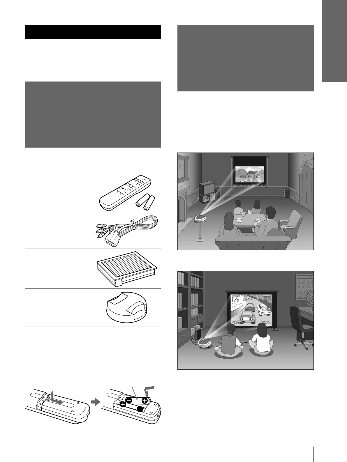
You can obtain good picture quality even when you
project the picture from the side of the screen (“SIDE
SHOT”) (1 page 7). You can enjoy home
entertainment with this projector i n various si tuations.
Enjoying home theater
Remote control (1),
Size AA (R6)
batteries (2)
Signal interface
cable (1)
Air filter (for
replacement) (1)
Lens cap (1)
AC power cord (1)
Operating Instructions (1)
Enjoying video games on a large screen
Inserting the batteries into the remote
control
Insert the batteries E side first
as shown in the illustration.
Unpacking / Step 1: Installing the Projector
5
GB
Page 6
Connections and
Preparations
Watching sports, etc. with your company
Viewing images, recorded by a digital
camera and stored in the “Memory Stick,” on
a large screen.
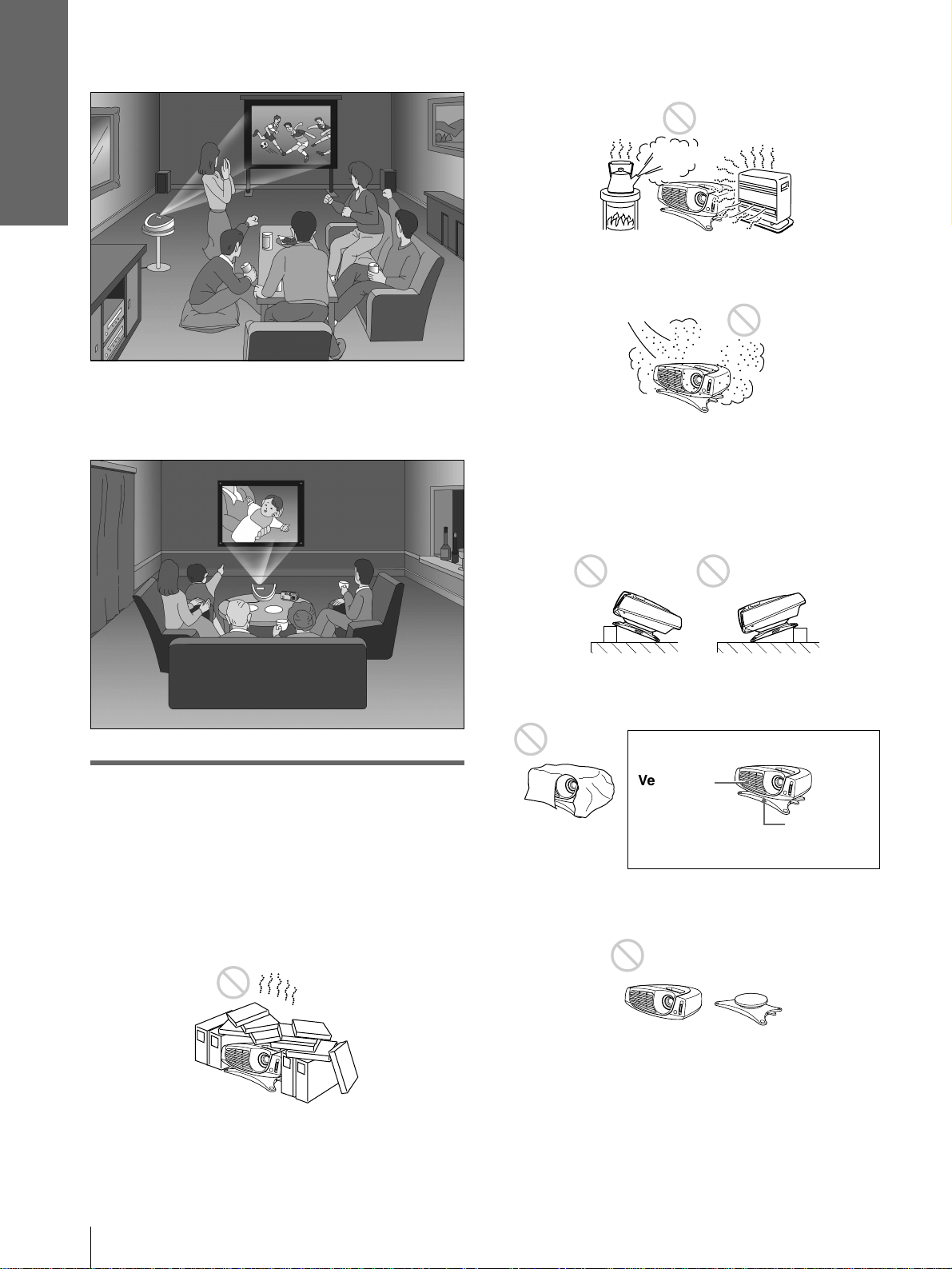
Highly heated and humid
Very dusty and extremely smoky
Do not use the projector under the following
conditions.
Tilting the unit out of the range of the
adjuster setting
Before Setting Up the
Projector
Do not place the proje ctor in the foll owi ng situations,
which may cause malfunction or damage to the
projector.
Poorly ventilated
Blocking the ventilation holes
Ventilation
holes
(exhaust)
Placing the projector without the adjuster
Ventilation
holes
(intake)
GB
Step 1: Installing the Projector
6
Page 7
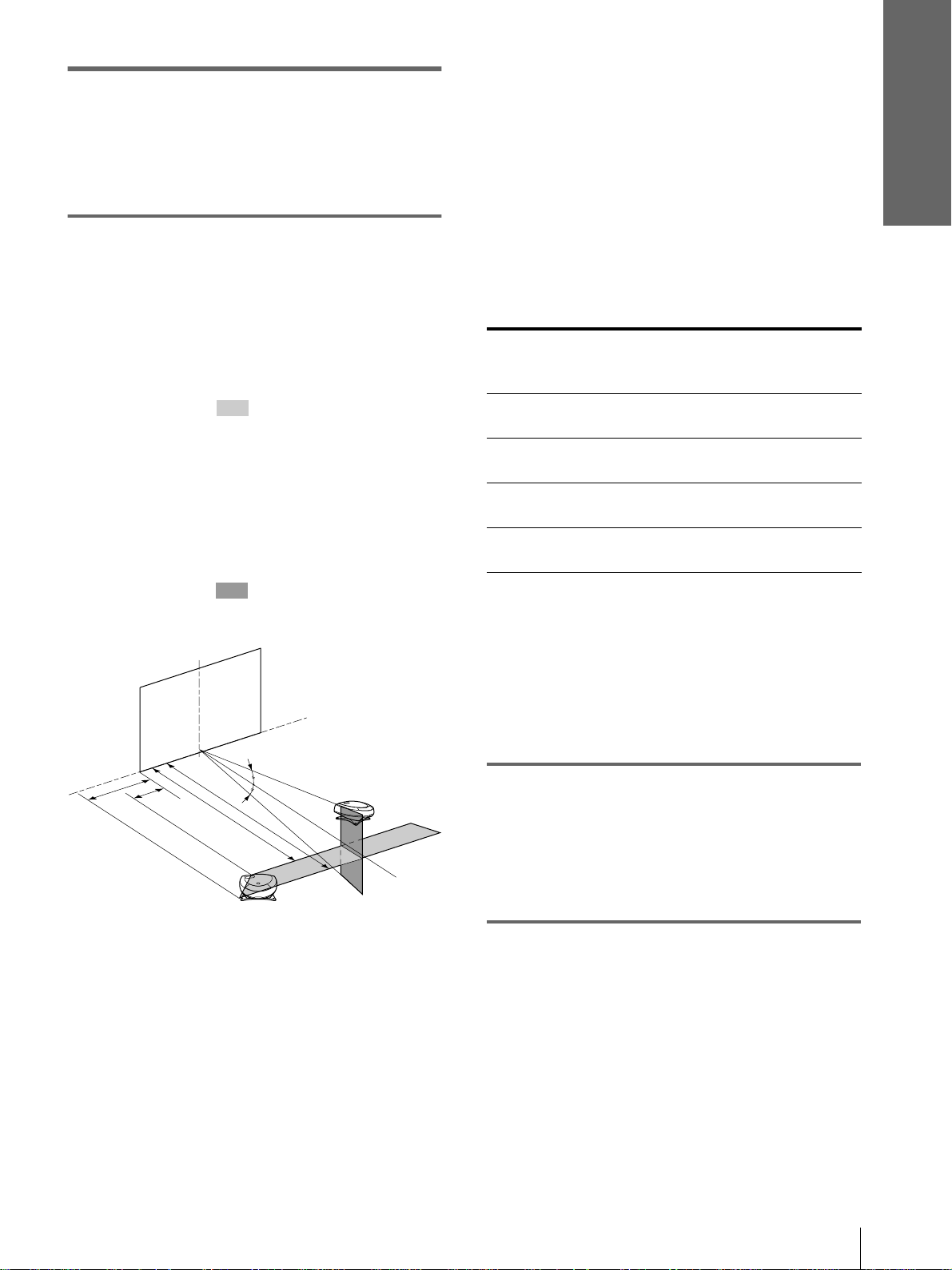
Installing the Projector and a
Screen
The installation distance between the projector and
screen varies depending on the size of the screen.
1
Determine the installation
position of the projector and
screen.
When projecting from the side (SIDE
SHOT)
Position the projector with the lens end come
within the area in the illustration, by using
the values a, b, c and d in the table below as a
guide. Align the bottom of the adjuster of the
projector with the bottom end of the screen.
When projecting from the center
You can change the projection angle using the
adjuster.
Position the projector with the lens end come
within the area in the illustrati on, by using
the valu es c and d in the t able belo w as a guide.
Screen
c: Maximum projection distance between the
screen and the center of the projector’s lens
when you use the horizontal distance a, or
when you place the pr oje ct or with the ce nt er
of the screen and the center of the lens
aligned.
d: Minimum projection distance between the
screen and the center of the lens when you
use the horizontal distance b, or when you
place the projector with the center of the
screen and the center of the lens aligned.
Unit: m (feet)
Screen
size
(inches)
a0.6
b0.4
c1.7
d1.6
When you project a 720p format signal,
computer’s signal, etc.
The table shows the distances when projecting the
conventional video signals. Distances used for
projecting a 720p format signal, computer’s signal
and data stored in the “Memory Stick” are shown on
page 41.
40 60 80 100 120 150
(2.0)
(1.3)
(5.6)
(5.2)
0.9
(3.0)
0.6
(2.0)
2.7
(8.9)
2.5
(8.2)
1.2
(3.9)
0.8
(2.6)
3.6
(11.8)
3.3
(10.8)
1.5
(4.9)
1.0
(3.3)
4.5
(14.8)
4.2
(13.8)
1.8
(5.9)
1.2
(3.9)
5.4
(17.7)
5.0
(16.4)
2.3
(7.5)
1.6
(5.2)
6.8
(22.3)
6.3
(20.7)
Connections and
Preparations
b
a
a: Maximum horizontal distance between the
right/left end of the screen and the center of
the projector’s lens when the projector is
placed on the side (for “SIDE SHOT”)
b: Horizontal distance between the right/left
end of the screen and the center of the lens
when the projector is placed on the side (for
“SIDE SHOT”)
c
d
Projector
10°
10°
2
Project an image on the screen
and adjust the picture so that it
fits the screen.
T o project an image, co nnect video equipment to
the projector. (1 page 8)
Step 1: Installing the Projector
7
GB
Page 8
Connections and
Preparations
Step 2:
Connecting the
Projector
When making connections, be sure to do the
following:
• Turn off all equipment before making any
connections.
• Use the proper cables for each connection.
• Insert the cable plugs properly; plugs that are not
fully inserted often generate noise. When pulling
out a cable, be sure to pull it out f rom the plug , n ot
the cable itself.
• When you connect your projector to PJ MULTI
INPUT, select the input signal with the INPUT-A
setting in the SET SETTING menu. (1 page
20)
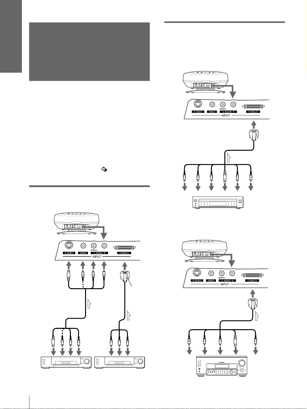
Connecting Using the Optional
Signal Interface Cables
To connect with a DVD player with
component video connectors/digital
BS tuner
Rear of the projector
Signal interface cable SIC-HS20
(not supplied)
to RGB/component
output
to audio
output
Connecting with video
equipment
Rear of the projector
S video or video/
audio cable
(not supplied)
to S
video or
video/
audio
output
to video/
Signal
interface
cable
(supplied)
audio
output
with
SONY
logo
upside
B
C
(PR)
R
S
Video
Audio L
Audio
R
C
(PB)
Y
DVD player with component video
connectors, digital BS tuner, etc.
To connect with an AV amplifier
Rear of the projector
Signal interface cable SIC-HS40
to component
video output
CB
(PB)CR(PR)
Y
(not supplied)
to video output
S
Video
Video
GB
Video equipment Video equipment
Step 2: Connecting the Projector
8
AV amplifier
Page 9
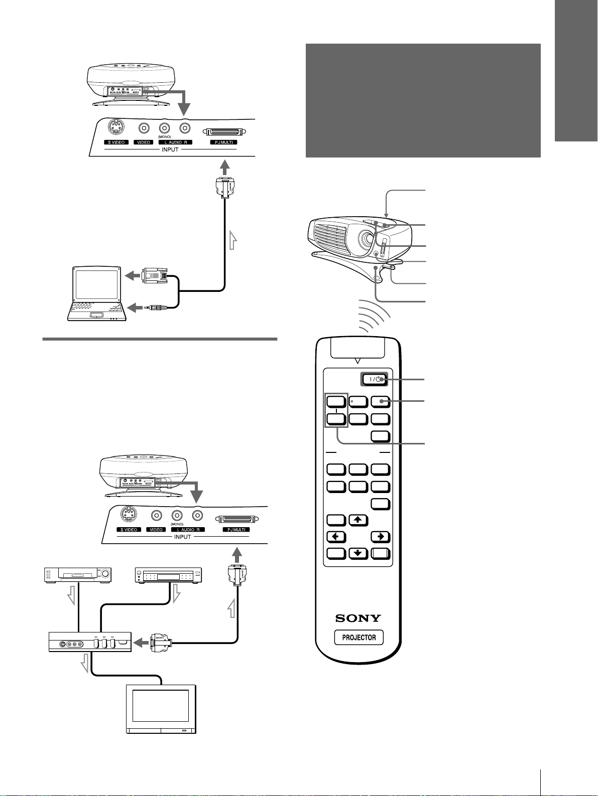
To connect with a computer
Connections and
Preparations
Rear of the projector
Signal interface cable
SIC-HS30 (not supplied)
Computer
to monitor output
to audio output
Connecting Using the Optional
Step 3: Adjusting
the Picture Size
and Position
Rear remote
control detector
6
5,8
Front remote control
detector
Adjuster stopper
6
Interface Unit
Using the optional interface unit allows you to
connect various video equipment, and to select the
output to the projector or TV from the connected
equipment simply by switching the select switch on
the interface unit.
Rear of the projector
VCR, etc.
Interface unit
IFU-HS1
DVD player, etc.
to PJ multi
output
PJ multi cable
(supplied with
the IFU-HS1)
SIDE
VOLUME
SHOT
+
–
VIDEO MEMORY
DYNAMIC STANDARD LIVING
USER 1
MENU
ENTER
INPUT
+
MS SLIDE
–
APA
USER 2 USER 3
OFF
RESET
2
4
7
TV
Step 3: Adjusting the Picture Size and Position
9
GB
Page 10
Connections and
Preparations
1
Plug the AC power cord into a
wall outlet.
The ON/STANDBY indicator lights in red and
the projector goes into standby mode.
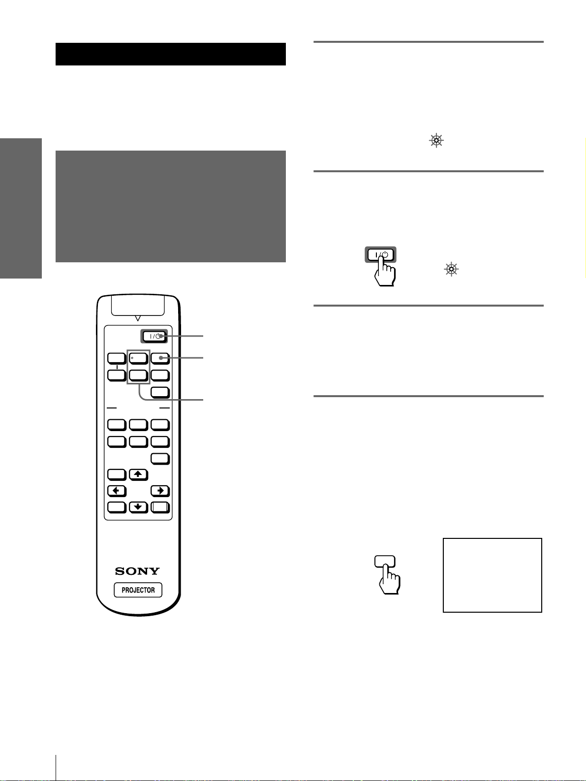
2
Press the [/1 (on/standby)
switch to turn on the projector.
The ON/STANDBY indicator lights in green.
3
Turn on the equipment
connected to the projector.
Refer to the operating instructions of the
connected equipment.
ON/
STANDBY
Lights in red.
ON/
STANDBY
Lights in green.
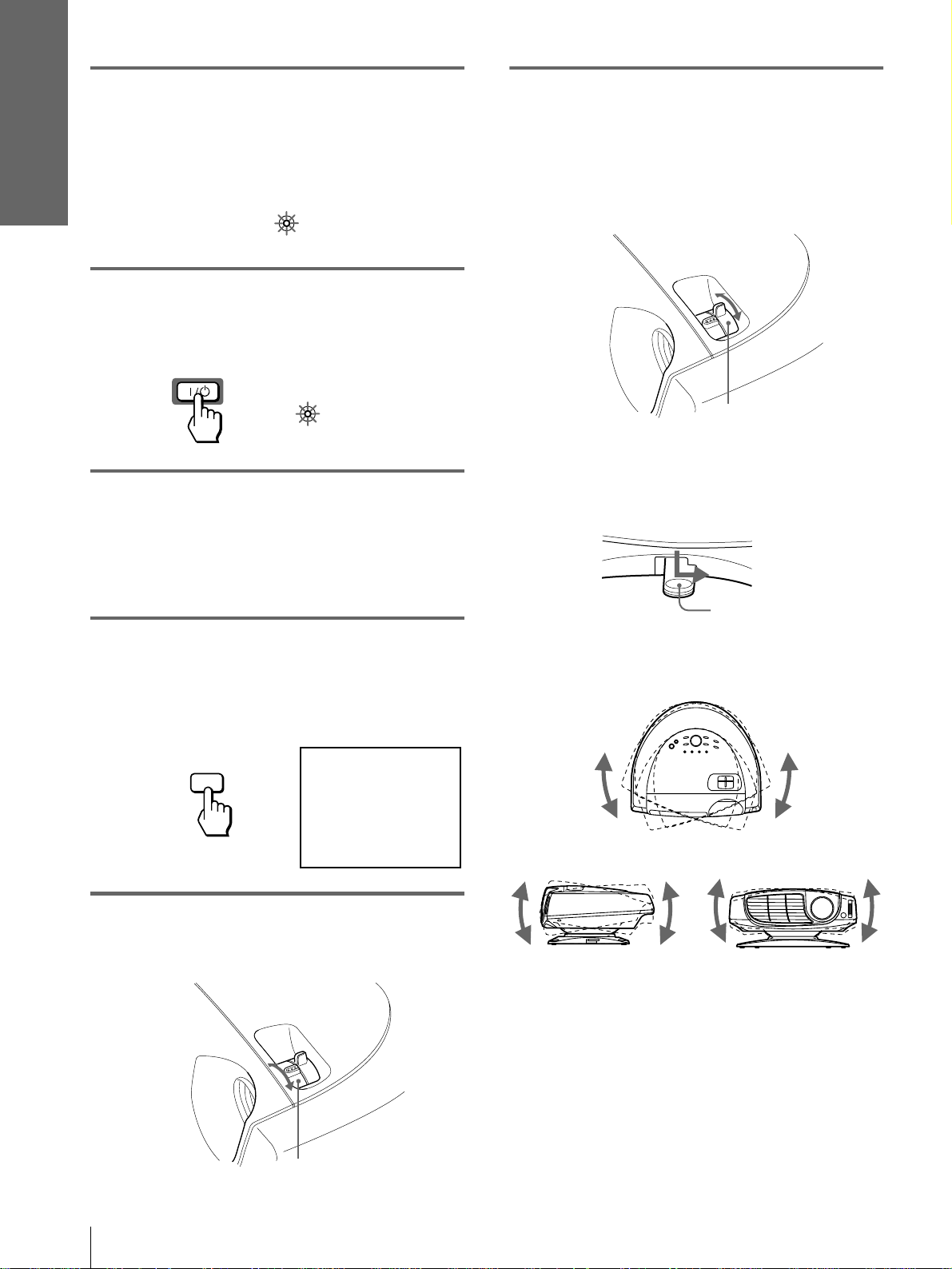
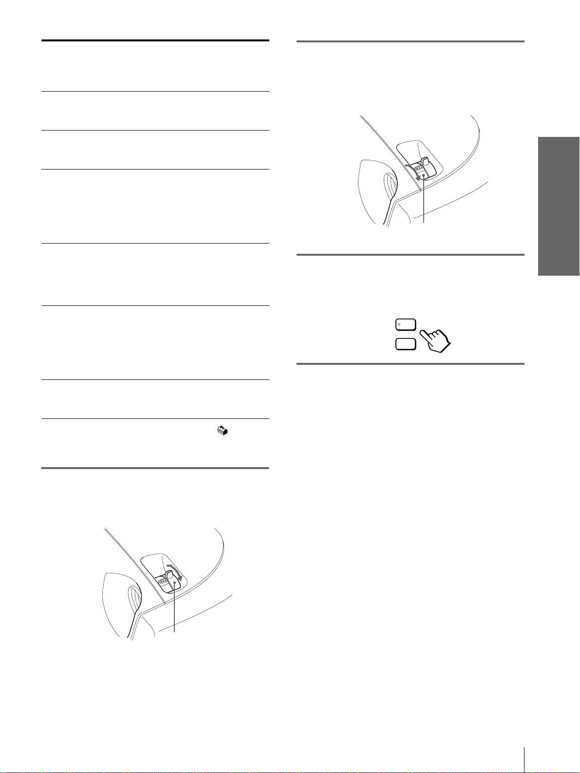
6
Adjust the size and position of
the picture to fit the screen
using the zoom lever and
adjuster.
Move the zoom lever to adjust the picture size.
Zoom lever
Use the adjuster to adjust the picture position.
Hold down and slide the adjuster stopper to the
right, move the projector, then replace the
stopper.
Adjuster stopper
4
Press INPUT to project the
picture on the screen.
Each time you press the button, the input
indication changes. (1 page 15)
INPUT
5
Adjust the focus roughly using
the focus lever.
VIDEO 1
You can move the projector vertically and
horizontally within the following ranges:
Up to 20° each for horizontal angle
Up to 10° each for
vertical angle
Up to 2° each for
tilting angle
GB
10
Focus lever
Step 3: Adjusting the Picture Size and Position
Page 11
Connections and
Preparations
When projecting from
the side
Screen
Picture
If you position the
projector on the left side
of the screen, adjust so
that the left side of the
picture fits the left side
of the screen. For the
projector positioned on
the right side, adjust so
that the right side of the
picture fits the right side
of the screen.
When projecting from
the center
Screen
Picture
If you position the projector
below the bottom of the
screen, adjust so that the
bottom edge of the picture
fits the bottom edge of the
screen. For the projector
positioned above the
bottom of the screen,
adjust so that the top edge
of the picture fits the top
edge of the screen.
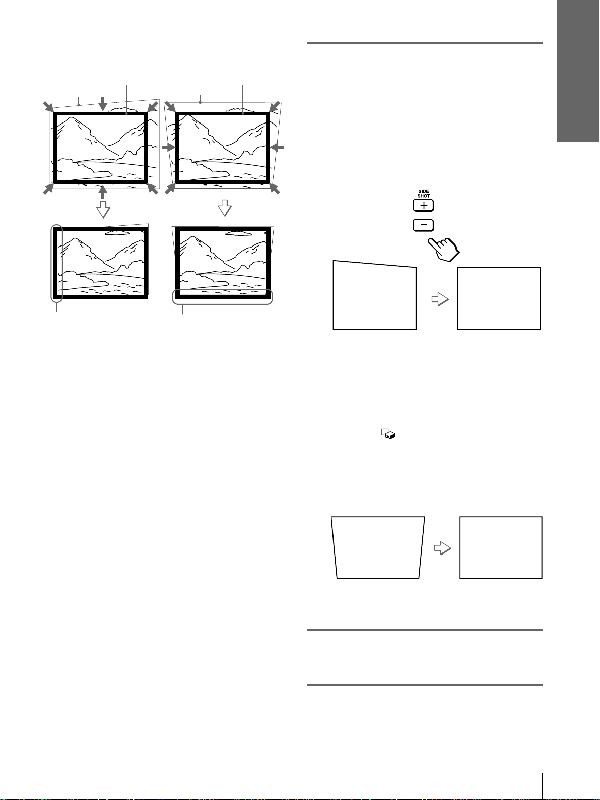
7
Adjust to correct the
trapezoidal distortion.
When projecting from the side
Corrects the horizontal distortion.
Press SIDE SHO T + o r – so that th e top edge of
the picture becomes paral lel to the bottom edge.
If the left side is l onger than the right side, pr ess
SIDE SHOT –.
Use SIDE SHOT + if the right side is longer.
To fine-adjust the distortion, press M or m.
When projecting from the center
Corrects the vertical distortion.
Use the menu. Select V (vertical) with the
KEYSTONE DIR setting in the INSTALL
SETTING menu. Next, adjust with the
DIGIT KEYSTONE setting so that the left side
of the picture be comes para llel t o the righ t si de.
(1 page 20)
If the top edge of the picture is longer than the
bottom edge, set to a plus value.
If the bottom edge is longer than the top edge,
set to a minus value.
8
Adjust the focus again using
the focus lever.
Step 3: Adjusting the Picture Size and Position
11
GB
Page 12
Connections and
Preparations
Step 4:
Selecting the
2
Press the [/1 (on/standby)
switch to turn on the projector.
The ON/STANDBY indicator lights in green.
Menu Language
You can select one of nine languages for displaying
the menu and other on-screen displays. The factory
default setting is English.
SIDE
VOLUME
SHOT
+
–
VIDEO MEMORY
DYNAMIC STANDARD LIVING
USER 1
INPUT
+
MS SLIDE
–
APA
USER 2 USER 3
OFF
2
3
MENU
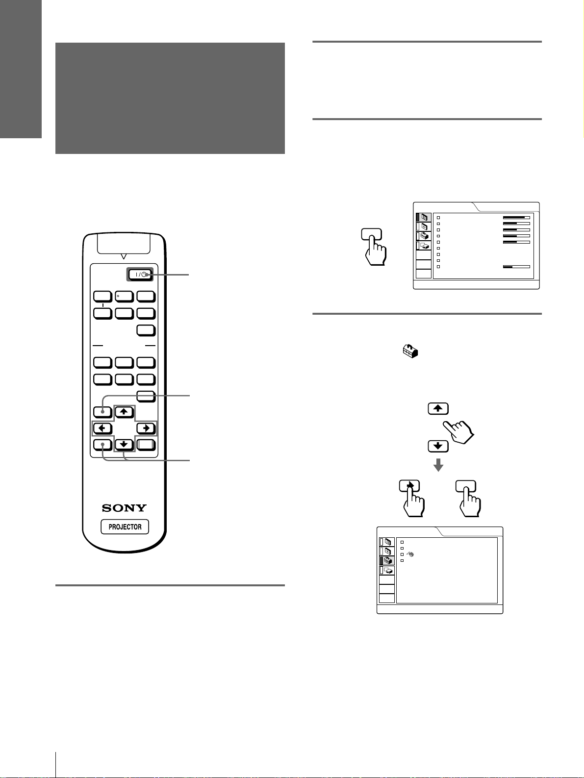
3
Press MENU.
The menu appears.
The menu presently selected is shown as a
yellow button.
PICTURE CTRL
CONTRAST:
BRIGHT:
MENU
4
Press M or m to select the SET
COLOR:
HUE:
SHARP:
D.PICTURE:
COLOR TEMP:
COLOR SYS:
VOLUME:
80
50
50
50
50
OFF
HIGH
AUTO
30
SETTING menu, and press
, or ENTER.
The selected menu appears.
VIDEO 1
ENTER
RESET
4,5,6
1
Plug the AC power cord into a
wall outlet.
The ON/STANDBY indicator lights in red and
the projector goes into standby mode.
SET SETTING
STATUS:
INPUT-A:
LANGUAGE
POWER SAVING
or
ON
COMPONENT
:
ENGLISH
:
OFF
ENTER
VIDEO 1
GB
12
Step 4: Selecting the Menu Language
Page 13
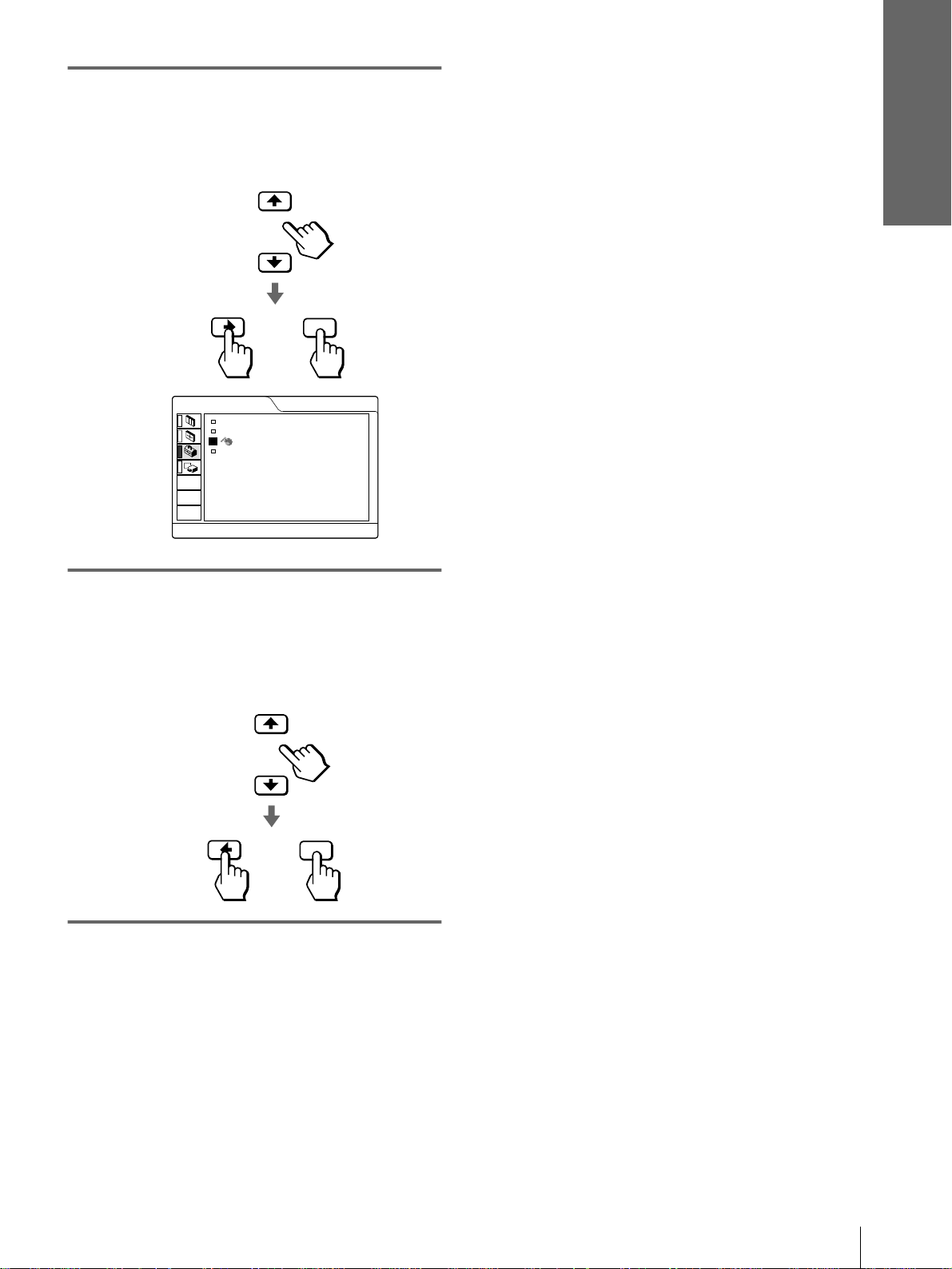
5
Press M or m to select
LANGUAGE, and press , or
ENTER.
ENTER
or
Connections and
Preparations
SET SETTING
STATUS:
INPUT-A:
LANGUAGE
POWER SAVING
6
Press M or m to select a
ON
COMPONENT
:
ENGLISH
:
OFF
language, and press < or
ENTER.
The menu changes to the selected language.
ENTER
or
VIDEO 1
To clear the menu
Press MENU.
Step 4: Selecting the Menu Language
13
GB
Page 14
Projecting
This section describes ho w to oper ate the projector to
view the pi cture from the equip ment co nnected t o the
projector . It also desc ribes how to adjust the qualit y of
the picture to suit your taste.
1
Plug the AC power cord into a
wall outlet.
The ON/STANDBY indicator lights in red and
the projector goes into standby mode.
ON/
STANDBY
Lights in red.
Projecting
Projecting the
Picture on the
Screen
SIDE
VOLUME
SHOT
+
–
VIDEO MEMORY
DYNAMIC STANDARD LIVING
USER 1
MENU
INPUT
+
MS SLIDE
–
APA
USER 2 USER 3
OFF
2
4
7
2
Press the [/1 (on/standby)
switch to turn on the projector.
The ON/STANDBY indicator lights in green.
ON/
STANDBY
Lights in green.
3
Turn on the equipment
connected to the projector.
Refer to the operating instructions of the
connected equipment.
4
Press INPUT repeatedly to
select the input you want to
project on the screen.
Display the indication of the input you want.
GB
14
ENTER
Projecting the Picture on the Screen
RESET
Example:To view the picture from the video
equipment connected to the VIDEO
INPUT jack.
VIDEO 1
INPUT
Page 15
To view the picture
from
Video equipment
connected to VIDEO
INPUT on the projector
Video equipment
connected to S VIDEO
INPUT on the projector
RGB/component
equipment connected to
PJ MULTI INPUT via
the optional signal
interface cable or the
interface unit
Video equipment
connected to PJ MULTI
INPUT via the optional
signal interface cable or
the interface unit
Video equipment
equipped with S VIDEO
connected to PJ MULTI
INPUT via the optional
signal interface cable or
the interface unit
“Memory Stick”
inserted into the
“Memory Stick” slot
*
Set the INPUT-A setting in the SET SETTING menu
according to the input signal. (1 page 20)
5
Move the zoom lever to adjust
Press
INPUT to
display
VIDEO 1 AUDIO INPUT
S-VIDEO 1 AUDIO INPUT
INPUT A
VIDEO 2 PJ MULTI
S-VIDEO 2 PJ MULTI
MS AUDIO INPUT
Sound is
heard from the
equipment
connected to
*
PJ MULTI
INPUT
INPUT
INPUT
the size of the picture.
6
Move the focus lever to adjust
the focus.
Adjust to obtain sharp focus.
Focus lever
7
Press VOLUME + or – to adjust
the volume.
VOLUME
+
–
To turn off the power
1 Press the [/1 (on/standby) switch.
A message “Power OFF?” appears on the screen.
2 Press the [/1 switch again.
The ON/ST ANDBY indicator flashes in green and
the fan contin ues to run to red uce the int ernal heat.
Also, the ON/ST ANDBY indicator flashes quickly
during which you will not be able to light up the
ON/STANDBY indicator with the [/1 switch.
Projecting
Zoom lever
3 Unplug the AC power cord from the wall
outlet after the fan stops running and the
ON/STANDBY indicator lights in red.
You can turn off the projector by ho lding the [/1 (on/
standby) switch for about one second, instead of
performing the above steps.
Projecting the Picture on the Screen
15
GB
Page 16

Selecting the
Picture Viewing
Mode
Projecting
You can select the picture viewing mode that best
suits the type of program or room condition.
DYNAMIC STANDARD LIVING
SIDE
SHOT
VOLUME
+
–
VIDEO MEMORY
USER 2 USER 3
USER 1
LIVING
Select for soft, film-like picture.
USER 1, 2 and 3
You can adjust the quality of the picture to suit your
taste and store the settings into the selected memory
of the projector. Press one of the USER 1, 2 and 3
buttons, then adjust the picture by using the menus.
The settings are stored, and you can view the picture
with the adjusted picture quality by pressing the
button. (1 page 20)
OFF
Select for the setting stored in each input that can be
selected with the INPUT b utton, or eac h input signal .
Tip
You can select the picture viewing mo de using the VIDEO
INPUT
+
MS SLIDE
MEMORY button on the projector. Each press of the button
selects the above item.
–
APA
OFF
VIDEO MEMORY buttons
DYNAMIC
STANDARD
LIVING
USER 1, 2 and 3
OFF
MENU
ENTER
RESET
Press one of the VIDEO MEMORY
buttons (DYNAMIC, STANDARD,
LIVING and USER 1, 2 and 3).
DYNAMIC
Select for enhanced picture contrast and sharpness.
STANDARD
Recommended for normal viewing condition in your
home.
Also select to reduce roughness when viewing the
picture with DYNAMIC.
GB
16
Selecting the Picture Viewing Mode
Page 17

Using the Menus
This section describes how to make various
adjustments and settings using the menus.
1
Press MENU.
The menu appears.
The menu presently selected is shown as a
yellow button.
Operation through
the Menus
SIDE
VOLUME
SHOT
+
–
VIDEO MEMORY
DYNAMIC STANDARD LIVING
USER 1
INPUT
+
MS SLIDE
–
APA
USER 2 USER 3
OFF
1
MENU
PICTURE CTRL
CONTRAST:
BRIGHT:
MENU
2
Press M or m to select a menu,
COLOR:
HUE:
SHARP:
D.PICTURE:
COLOR TEMP:
COLOR SYS:
VOLUME:
80
50
50
50
50
OFF
HIGH
AUTO
30
and press , or ENTER.
The selected menu appears.
Menus
SET SETTING
ENTER
or
Items
STATUS:
INPUT-A:
LANGUAGE
POWER SAVING
ON
COMPONENT
:
ENGLISH
:
OFF
VIDEO 1
Using the Menus
Settings
VIDEO 1
ENTER
RESET
RESET button
2,3,4
3
Select an item you want to
adjust.
Use M or m to select an item, and press , or
ENTER.
SET SETTING
or
ENTER
STATUS:
INPUT-A:
POWER SAVING
LANGUAGE
ON
COMPONENT
:
ENGLISH
:
OFF
VIDEO 1
Operation through the Menus
17
GB
Page 18

4
Make the setting or adjustment
on an item.
Menu
When changing the adjustment level
Configurations
To increase the value, press M or ,.
To decrease the value, press m or <.
Press ENTER to restore the original screen.
When changing the setting
Press M or m to change the setting.
Press < or ENTER to restore the original
screen.
The projector is equi pped with four m enu pa ges. The
items that can be adj usted in each menu are des cribed
on pages 19 and 20.
PICTURE CTRL menu
SET SETTING
STATUS:
INPUT-A:
LANGUAGE
POWER SAVING
ON
COMPONENT
:
ENGLISH
:
ON
VIDEO 1
The PICTURE CTRL menu is used for adjusting the
picture. You can also adjust the volume with this
menu.
Using the Menus
ENTER
or
To clear the menu
Press MENU.
INPUT SETTING menu
The INPUT SETTING menu is used to adjust the
input signal. You can adjust the size and position, etc .
of the picture.
SET SETTING menu
The SET SETTING menu is used for changing the
settings of the projector.
To reset items that have been
adjusted
Select the item you want to reset, then press RESET.
“Complete!” appears on the screen and the setting is
reset to its factory preset value.
Items that can be reset are:
• CONTRAST, BRIGHT, COLOR, HUE, SHARP
and RGB ENHANCER in the PICTURE CTRL
menu
• DOT PHASE, SIZE H and SHIFT in the INPUT
SETTING menu
• DIGIT KEYSTONE in the INSTALL SETTING
menu
INSTALL SETTING menu
The INST ALL SETTING menu is used for correcting
distortion. You can change the display position,
intensity of the backgroun d picture, e tc., of the menu
screen.
GB
18
Menu Configurations
Page 19

Menu Items
Adjustable items are li mit ed a cco rdi ng to t he i nput signa ls . It em s that can not be ad jus te d ar e no t displ ay ed i n th e
menu. (1 page 42)
Menu Item Description
PICTURE
CTRL
INPUT
SETTING
CONTRAST The higher the setting, the greater the contrast. The lower the setting, the lower
the cotrast.
BRIGHT (brightness) The higher the setting, the brighter the picture. The lower the setting, the darker
the picture.
COLOR The higher the setting, the greater the intensity. The lower the setting, the lower
the intensity.
HUE The higher the setting, the more greenish the picture becomes. The lower the
setting, the more purplish the picture becomes.
SHARP (sharpness) The higher the setting, the sharper the picture. The lower the setting, the softer
the picture.
RGB ENHANCER Adjusts the picture sharpness when computer signals are input.
D. (Dynamic)
PICTURE
GAMMA MODE GRAPHICS: Reproduces the photos in natural tones.
COLOR TEMP HIGH: Gives the white colors a blue tint.
COLOR SYS (System) Select the color system of the input signal.
VOLUME Adjusts the volume. It can be adjusted for each of the inputs selected with the
DOT PHASE When a signal from a computer is input, adjusts the picture for clearer picture
SIZE H When a signal from a computer is input, adjusts the horizontal size of the
SHIFT As the setting for H (horizontal) increases, the picture moves to the right, and as
SCAN CONV (Scan
converter)
ASPECT 4:3: Select when the 4:3 aspect ratio picture is input.
ON: Emphasizes the black color.
OFF: Reproduces the dark portions of the picture accurately, in accordance
with the source signal.
TEXT: Contrasts black and white. Suitable for images that contain lots of text.
MIDDLE: Gives the white colors a neutral tint.
LOW: Gives the white colors a red tint.
3.58
AUTO: NTSC
Normally, set to this position.
PAL -M /N: PAL-M/PAL-N and NTSC
When the PAL-M, PAL-N or NTSC
set to AUTO, set to this position if the picture is distorted or colorless.
INPUT button .
after the picture is adjusted by pressing the APA button.
picture. The higher the setting, the wider the picture. The lower the setting, the
narrower the picture.
the setting decreases, the picture moves to the left. Use < or , to adjust the
horizontal position.
As the setting for V (vertical) increases, the picture moves up , and as the s etting
decreases, the picture moves down. Use M or m to adjust the vertical position.
ON: Displays a computer signal according to the screen size. The picture will
be slightly softer.
OFF: Displays a computer signal as it is input. The picture will be clear but the
picture size will be smaller.
Note
When SVGA or XGA signal is input, this item will not be displayed.
16:9: Select when the 16:9 aspect ratio picture (sqeezed) is input from
equipment such as a DVD player.
, PAL, SECAM and NTSC
4..43
(switched automatically).
3.58
(switched automatically).
3.58
signal is input with COLOR SYS
Using the Menus
Menu Configurations
19
GB
Page 20

Menu Item Description
INPUT
SETTING
(continued)
Using the Menus
SET
SETTING
INSTALL
SETTING
VIDEO MEMORY You can select picture viewing mode that best suits the type of picture or the
environment.
OFF: Select for the setting stored in each input channel or input signal.
DYNAMIC: Select for enhanced picture contrast and sharpness.
STANDARD: Recommended for normal viewing condition. Also select to
reduce roughness when viewing the picture with DYNAMIC.
LIVING: Select for soft, film-like picture.
USER 1, 2 and 3: You can adjust the quality of the picture to suit your taste and
store the settings. Once the settings are stored, you can view the picture with
the adjusted picture quality by pressing the button.
To store the settings
1 Select USER 1, USER 2 or USER 3.
2 Adjust the items you want in the menus.
Items that can be stored are:
CONTRAST, BRIGHT, COLOR, HUE, SHARP, RGB ENHANCER,
D.PICTURE, COLOR TEMP, COLOR SYS, SCAN CONV, ASPECT.
Tip
You can also adjust the picture quality in DYNAMIC, STANDARD or
LIVING mode. To reset to the factory setting, press RESET.
STATUS Set to OFF to turn off the on-screen displays except for the menus, message
when turning off the po wer, and warning messages.
To display all of the on-screen display again, set to ON.
INPUT-A Selects the signal input from the PJ MULTI connector.
COMPUTER: Inputs the signal from a computer.
COMPONENT: Inputs the component or progressi v e componen t signal from a
DVD player, digital BS tuner, etc.
VIDEO GBR: Inputs the signal from a TV game, DVD player or HDTV
broadcast.
LANGUAGE Selects the language used in the menu and on-screen displays. Available
languages are: English, French, German, Italian, Spanish, Japanese, Chinese,
Portuguese and Korean.
POWER SAVING When set to ON, the POWER SAVING indicator lights. The projector goes into
power saving mode if no signal is input for 10 minutes, and the lamp goes out
and the cooling fan keeps running. In power saving mode, no button functions
for the first 60 seconds. It is cancelled when a signal is input or any button is
pressed. If you do not set the projector to power saving mode, select OFF.
KEYSTONE MEM
(memory)
DIGIT KEYSTONE Corrects the trapezoidal distortion caused by the projection angle. Use this item
KEYSTONE DIR When the picture is a vertical trapezoid ( ), select V. Next, correct the
MENU POSITION Selects the display position from TOP LEFT, BOTT OM LEFT, CENTER, TOP
MENU COLOR Selects the tone of the menu display from STANDARD, WARM, COOL,
MENU
BACKGROUND
LAMP TIMER Indicates how long the lamp has been turned on.
ON: DIGIT KEYSTONE setting is stored.
The data is retrieved when the projector power is turned on. The setting will
remain the same every time.
OFF: DIGIT KEYSTONE is reset to “0” when the power is turned on next
time.
after selecting the type of distortion, H (horizontal) or V (vertical), with
KEYSTONE DIR.
distortion with DIGIT KEYSTONE. When the picture is a holizontal trapezoid
( ), select H, then correct the distortion with DIGIT KEYSTONE.
RIGHT and BOTTOM RIGHT.
GREEN or GRAY.
Selects the intensity o f the backgro und pictu re of the menu display from D AR K,
STANDARD or LIGHT.
GB
20
Menu Configurations
Page 21

About the Preset Memory No.
Adjusting Picture Quality of a
This projector has 32 types of preset data for input
signals (the preset m emory). When the preset s ignal is
input, the projector automatically detects the signal
type and recalls th e data for the signal from the preset
memory to adjust it to an optimum picture. The
memory number and signal type of that signal are
displayed in the INPUT SETTING menu.
INPUT SETTING
DOT PHASE:
SIZE H:
SHIFT:
SCAN CONV:
15
800
H: 200 V: 30
ON
No. 13
640 480
INPUT-A
Memory No.
Signal type
Y ou can als o adjust the preset data through the INPUT
SETTING menu.
This projector also has 20 types of user mem ories for
INPUT-A into which you can save the setting of the
adjusted data for an unpreset input signal.
When an unpreset signal is input for the first time, a
memory number is displayed as 0. When you adjust
the data of the signal in the INPUT SETTING menu,
it will be registered to the projector. If more than 20
user memories are registered, the newest memory
always overwrites the oldest one.
See the chart on page 43 to find if the signal is
registered to the preset memory.
Signal from the Computer
You can automatically adjust to obtain the clearest
picture when projecting a signal from the computer.
1 Project a still picture from the computer.
2 Press the APA button.
When the picture is adju sted properly, “complete”
appears on the screen.
Notes
• Press the APA button when the full image is displayed on the
screen. If there are black edges around the ima ge, t he APA
function will not function properly and the image may extend
beyond the screen.
• If you switch the input signal or re-connect a computer, press
the APA button again to get the suitable picture.
• To restore the ori ginal screen, press the APA button again
during the adjustment.
• The picture may not be adjust ed properly depending on the
kinds of input signals.
• Adjust the items in the INPUT SETTING menu when you
adjust the picture manually. (1 page 19)
Using the Menus
Since the data is recalled from the preset memory
about the following signals, you can use these preset
data by adjusting SIZE H. Make fine adjustment by
adjusting SHIFT.
Signal Memory
No.
Super Mac-2 23 1312
SGI-1 23 1320
Macintosh 19” 25 1328
Note
When the aspect ratio of input signal is other than 4:3, a part of the
screen is displayed in black.
SIZE
Menu Configurations
21
GB
Page 22

Using a “Memory Stick”
Before using a “Memory Stick”
Terminal
This section describes how to view the still images
that are recorded by a digital camera and stored in a
“Memory Stick.” You can make a slide show using
the images, disp lay an inde x screen of the images, etc.
About a “Memory
Stick”
On “Memory Stick”s
“Memory Stick” is a new compact, portable and
versatile IC recording medium with a data capacity
that exceeds a floppy disk. “Memory Stick” is
specially designed for e xchanging and sh aring di gital
data among “Memory Stick” compatible products.
Because it is re mov abl e, “Memory Stick” can also be
used for external data storage.
Types of “Memory Stick”s
Using a “Memory
Stick”
There are two type s of “Memory Stick”s: MagicGate
“Memory Stick”s that are equipped with the
MagicGate copyright protection technology and
general “Memory Stick”s. You can use both types of
“Memory Stick” with your projector. However,
because your projector does not support the
MagicGate standards, data recorded in the “Memory
Stick” is not subject to MagicGate copyright
protection.
Write-protect
tab
Labeling
position
• You cannot rotate or erase still images when the
write-protect tab on the “Memory Stick” is set to
LOCK.
• We recommend backing up important data.
• Image data may b e dama ged in the foll o wing c ases:
If you remov e the “Memory Stick,” turn the power
–
off, or detach the batt ery for replacement when the
access lamp is flashing.
If you use a “Memory Stick” near static electricity
–
or magnetic fields.
Notes
• Prevent metallic objects or your finger from coming into
contact with the metal parts of the connecting section.
• Do not attach an y other material than the supplied label onto the
label space.
• Attach the label to the pre scri be d label ing po si tio n. Mak e sure
the label is attached to the labeling position properly.
• Do not bend, drop or apply strong shock to a “Memory Stick.”
• Do not disassemble or modify a “Memory Stick.”
• Do not let the “Memory Stick” get wet.
• Do not use or keep a “Memory Stick” in locations that are:
– Extremely hot such as in a car parked in the sun or under the
scorching sun.
– Under direct sunlight.
– Very humid or subject to corrosive gases.
• When you carry or store a “Memory Stick,” put it in its case.
About formatting “Memory Stick”s
When “Memory Stick”s are shipped f rom the f actory ,
they are already formatted to a special standard
format. When you format “Memory Stick”s, we
recommend formatting them on this unit.
On MagicGate
MagicGate is copyright protection technology that
uses encryption technology.
Format that can be displayed with this
projector
Image data recorded with a digital camera and
recorded on a Memory Stick in the following format:
Images (DCF-compatible) compressed in the JPEG
(Joint Photographic Experts Group) format
(extension: .jpg)
Caution when formatting “Memory Stick”s
on a personal computer
Pay attention to th e following points when formatting
“Memory Stick”s on the personal computer, for
example, that you are using.
Operation of “Memory Stick”s formatted on the
personal computer is not guaranteed on this unit. To
use a “Memory Stick” that has been formatted on the
personal computer, the “Memory Stick” must be
reformatted on this unit. Note that in this case all data
stored on the “Memory Stick” will be lost.
GB
22
About a “Memory Stick”
Page 23

Access Lamp
If the access lamp is turned on or is flashing, data is
being read from or writ ten to the “Memory Stick.” Do
not shake the projector or subject it to shock. Do not
turn off the power of the projector or remove the
“Memory Stick.” This may damage the data.
Preparing for Viewing
the Still Picture Stored
Notes
• To prevent data loss, make backup of data
frequently. In no event will Sony be liable for any
loss of data.
• Unauthorized recording may be contrary to the
provisions of copyright law.
• The “Memory Stick” application software may be
modified or changed by Sony without prior notice.
.....................................................................................
•“Memory Stick” and are trademarks of Sony
Corporation.
•“MagicGate Memory Stick” and are trademarks of Sony
Corporation.
in a “Memory Stick”
Inserting a “Memory Stick”
Insert the “Memory Stick” into the “Memory Stick”
slot on the front of the projector.
“Memory Stick”
Insert the “Memory Stick” in the
direction of the arrow until it clicks.
To remove the “Memory Stick”
When the access lamp is turned off, press the
“Memory Stick” and remove your hand. As the loc k
is released, remove the “Memory Stick.”
Using a “Memory
Stick”
Access lamp
Preparing for Viewing the Still Picture Stored in a “Memory Stick”
23
GB
Page 24

Using the MS (“Memory
Stick”) Home
Viewing Still Images
The initial display on the screen is MS Home when
you select MS with the INPUT bu tton. The MS home
display is used for ex ecuting an ev ent (e.g., slide show
with JPEG Viewer), setting the Startup and
initializing a “Memory Stick.” The guide for the
button operation is displa yed at the bo ttom of the M S
home display. The selected item is displayed in
yellow.
Press INPUT to select MS.
MS home appears.
EVENT
EVENT
SETTING
“MEMORY STICK”
The name of the
selected contents
will be displayed.
*
JPEG Viewer
Slide Show
Index
Select Contents
in Sequence —
Slide Show
You can run a slide show by using still pi ctures (DCFcompatible) of the J PEG form at r ecord ed b y a digi tal
camera. You can advance a slide automatically or
manually.
SIDE
VOLUME
SHOT
+
–
VIDEO MEMORY
DYNAMIC STANDARD LIVING
INPUT
+
MS SLIDE
–
APA
1
MS SLIDE button
USER 2 USER 3
USER 1
MS home mark
Using a “Memory
Stick”
* Multiple still pictures are inc lu ded in the conte n ts. The
contents may include individual still pictures and other
contents. You must select contents when y ou are view ing a still
picture stored in a “Memory Stick.”
** Several small pictures inclu ded in the contents can be
displayed at one time. They are called thumbnails.
First two thumbnails
included in the selected contents
will appear.
**
that are
1
MENU
ENTER
Select MS by pressing the
OFF
RESET
2-9
INPUT button to display the
MS home. (1111 left column)
GB
24
Viewing Still Images in Sequence — Slide Show
Page 25

2
d
.
Press M or m to select EVENT
, and press ENTER.
EVENT
JPEG Viewer
Slide Show
Index
Select Contents
3
Press M or m to select “Select
Contents,” and press ENTER.
The sub menu for se lecting the c ontents appears.
to upper stage
Currently selected contents
EVENT
JPEG Viewer
Slide Show
Index
Select Contents
DCIM
0100MSDCF
0101MSDCF
0102MSDCF
0103MSDCF
0104MSDCF
0105MSDCF
5
Press ENTER.
The selected contents name and the first two
thumbnails are displayed.
When you want t o vie w all of the pic tures in th e
selected contents, select “Index” and press
ENTER.
EVENT
JPEG Viewer
Slide Show
Index
Select Contents
DCIM
6
Press M or m to select “Slide
Show,” and press ENTER.
The sub menu for setting the following items
appears.
EVENT
JPEG Viewer
Slide Show
Index
Select Contents
DCIM
Execute
Return
Effect
Advan.Slds.
Interval
Off
Auto
1 sec
Using a “Memory
Stick”
When the JPEG
pictures are save
Pictures or contents included
in the current contents
Note
The contents are sorted numerically and alp habetically up
to 256 contents. The later contents will not be sorted.
4
Press M or m to select the
in the current
contents, one of
them is displayed
contents you want to use for
your slide show, and press
ENTER.
When you want to select contents other than
those displayed on the m enu, select v or V, then
press ENTER.
Effect: set the effect when the slide is
displayed.
Advan. Slids : set to advance a next slide
automatically (“Auto”) or manually
(“Manual”).
Interval: set the period for which one slide is
displayed. When “Advan. Slids” is set to
“Manual,” this item does not work. Th e time
is about right.
7
Press M or m to select the item,
and press ENTER.
Viewing Still Images in Sequence — Slide Show
25
GB
Page 26

8
Press M or m to set the
selected item, and press
ENTER.
EVENT
JPEG Viewer
Slide Show
Index
Select Contents
DCIM
Execute
Effect
Advan.Slds.
Interval
Return
Off
Auto
5 sec
Displaying Index
Pictures on the
Full Screen
You can display 9 inde x pictures (th umbnail pict ures)
contained in the selected contents at one time.
MENU
ENTER
RESET
2
9
After setting all the items,
press M or m to select
“Execute” and press ENTER.
When you set “Advan. Slids” to “Auto,” the slide
show starts automatically.
When you set to “Manual,” use the < or m
button to advance a next slide. To return to the
previous slide, use the , or M button.
1
Using a “Memory
Stick”
To end the slide show
Press MS SLIDE or ENTER.
To return to the MS home before executing
the slide show
Select “Return” in step 9 above.
Executing the Slide Show Promptly
As the settings are store d even if you change the i nput
after performing steps 1 to 8, press MS SLIDE just as
you start the slide sh ow. The input is cha nged to M S
and the slide show starts promptly.
Perform steps 1 through 5 in
“Viewing Still Images in
Sequence — Slide Show.” (1111
page 24)
2
Press M or m to select “Index,”
and press ENTER.
The index screen appears, and 9 index pictures
of the selected contents are displayed.
GB
26
Displaying Index Pictures on the Full Screen
Reciipe
flour - - - - 2
sugar - - - 1/2
salt - - - - - 1/2
butter - - - 1
Page 27

When more than 9 pictures are
contained in the contents
You can display the pictures other than the displyed
ones by pressi ng v (pr e vious 9 pictur es) o r V (next 9
pictures) and ENTER.
To start a slide show with the index
screen
Press M, m, < or , to select a picture from whic h
a slide show starts, then press MS SLIDE.
Note
The index pictures are sorted numerically and alphabetically up to
256 pictures. The later pictures will not be sorted.
Displaying a FullScreen Picture
You can project one of the index pictures on the full
screen.
Displaying the Index Menu
Press M, m, < or , to select a picture, and press
ENTER.
The index menu for t he s ele cted pi ct ure i s di splaye d.
With this menu you can make various settings for
each picture. (1 pages 27 to 32)
Date when the picture is
recorded
Name given to each picture
(displayed alphabet and
numbers only)
Resolution
Sequential number/total
number of pictures in the
Indicates when the protect
function (1111 page 29) is set
Indicates when a picture is
registered as the startup
picture (1111 page 30)
contents
to a picture.
No.: 5/32
Size: 1024x768
File: SPORTS
Date:7/29/2001
14:22
Full Screen
Reciipe
flour - - - - 2
sugar - - - 1/2
salt - - - - - 1/2
butter - - - 1
Close
Return
Protect
Rotate
Startup
MENU
ENTER
RESET
2-4
1
Perform steps 1 through 5 in
“Viewing Still Images in
Sequence — Slide Show.” (1111
page 24)
2
Press M or m to select “Index,”
and press ENTER.
The index pictures of the selected contents are
displayed.
Using a “Memory
Stick”
To return to the MS home
Select “Return” and press ENTER.
Delete
Index menu
Setting items
Displaying a Full-Screen Picture
27
GB
Page 28

3
Press M, m, < or , to select
the picture you want to display
on the full screen, and press
ENTER.
The Index menu appears.
No.: 5/32
Size: 1024x768
File: SPORTS
Date:7/29/2001
Full Screen
Reciipe
flour - - - - 2
sugar - - - 1/2
salt - - - - - 1/2
butter - - - 1
4
Press M or m to select “Full
Close
Return
Protect
Rotate
Startup
Delete
Screen,” and press ENTER.
The selected picture is projected to fit the
screen.
14:22
Rotating a Still
Picture
You can rotate a still picture in 90° steps.
MENU
ENTER
RESET
2-5
To display a previous or next slide
To display the next slide, pre ss , or m. To return to
1
Using a “Memory
the previous slide, press < or M.
To return to the Index screen
Stick”
Press MS SLIDE or ENTER.
Perform steps 1 through 5 in
“Viewing Still Images in
Sequence — Slide Show.” (1111
page 24)
2
Press M or m to select “Index,”
and press ENTER.
The index pictures of the selected contents are
displayed.
GB
28
Rotating a Still Picture
Page 29

3
Press M, m, < or , to select
the picture you want to rotate,
and press ENTER.
The Index menu appears.
Protecting an
Important Still
No.: 5/32
Size: 1024x768
File: SPORTS
Date:7/29/2001
14:22
Full Screen
Close
Return
Protect
Rotate
Startup
Delete
4
Press M or m to select
Reciipe
flour - - - - 2
sugar - - - 1/2
salt - - - - - 1/2
butter - - - 1
“Rotate,” and press ENTER.
5
Press M or m to select the
direction of rotation,
(clockwise) or
(counterclockwise), and press
ENTER.
The picture rotates 90° every pressing of the
ENTER button.
Notes
• You cannot rotate a picture which is protected. (1 right
column)
To rotate it, release the protection on that picture.
• When the write-protect tab on the “Memory Stick” is set to
LOCK, you cannot rotate the pictures stored in that “Memory
Stick.”
Picture
You can protect a still picture to prevent it from
accidental erasure.
MENU
ENTER
RESET
2-5
1
Perform steps 1 through 5 in
“Viewing Still Images in
Sequence — Slide Show.” (1111
page 24)
2
Press M or m to select “Index,”
and press ENTER.
The index pictures of the selected contents are
displayed.
Using a “Memory
Stick”
Protecting an Important Still Picture
29
GB
Page 30

3
Press M, m, < or , to select
the picture you want to
protect, and press ENTER.
The Index menu appears.
Projecting a Selected
Picture When the Power
No.: 5/32
Size: 1024x768
File: SPORTS
Date:7/29/2001
14:22
Full Screen
Reciipe
flour - - - - 2
sugar - - - 1/2
salt - - - - - 1/2
butter - - - 1
Close
Return
Protect
Rotate
Startup
Delete
Is Turned On — Startup
When the projector is turned on, the specific still
picture stored in the projector is projected
automatically for ab out one m in ute , even if no signal
is input. You can change this still picture to the one
you prefer.
Registering a Still Picture as
4
Press M or m to select
“Protect,” and press ENTER.
5
Press M or m to select “On” or
“All on,” and press ENTER.
On: A picture selected on the Index screen is
protected.
Using a “Memory
Stick”
All on: All the pictur es in the sele cted contents
are protected.
The protect mark appears in the I ndex menu for
the protected picture.
the Startup Picture
When you want to use a picture stored in your
“Memory Stick” as the startup picture, register the
picture in the “Memory Stick.”
MENU
ENTER
RESET
2-5
GB
To release protection
Select “Off” or “All off” in step 5.
Selecting “Off” releases the protection for the
selected picture. Selecting “All off” releases the
protection for all th e pictures in the sel ected co ntents .
30
Projecting a Selected Picture When the Power Is Turned On — Startup
1
Perform steps 1 through 5 in
“Viewing Still Images in
Sequence — Slide Show.” (1111
page 24)
2
Press M or m to select “Index,”
and press ENTER.
The index pictures of the selected contents are
displayed.
Page 31

3
Press M, m, < or , to select
the picture you want to use as
the startup picture, and press
ENTER.
The Index menu appears.
No.: 5/32
Size: 1024x768
File: SPORTS
Date:7/29/2001
Full Screen
Reciipe
flour - - - - 2
sugar - - - 1/ 2
salt - - - - - 1/2
butter - - - 1
Close
Return
Protect
Rotate
Startup
Delete
14:22
Setting the Startup Picture
SIDE
VOLUME
SHOT
+
–
VIDEO MEMORY
DYNAMIC STANDARD LIVING
USER 1
MENU
INPUT
+
MS SLIDE
–
APA
USER 2 USER 3
OFF
1
4
Press M or m to select “Str.
up,” and press ENTER.
5
Press M or m to select “Entry,”
and press ENTER.
The startup mark is displa yed in the Index menu.
You can register one picture used for the startu p
picture, per one “Memory Stick.”
ENTER
RESET
2-4
1
Select MS by pressing the
INPUT button to display MS
home. (1111 page 24)
2
Press M or m to select
SETTING , and press
ENTER.
3
Press M or m to select
“Startup,” and press ENTER.
SETTING
Startup: Original
Using a “Memory
Stick”
Original
Custom
Off
Projecting a Selected Picture When the Power Is Turned On — Startup
31
GB
Page 32

4
MENU
ENTER
RESET
Press M or m to select the item
used for startup picture, and
press ENTER.
Original: Select to use the original picture
stored in the projector. This is the factory
setting.
Custom: Select to use t he pi cture re giste red i n
the index screen and stored in the “Memory
Stick.” (1 page 30)
Off: Select when you do not set the startup.
Notes
• When you want to clear the startup screen while displaying it,
press M/m/</,, or ENTER.
• When you are using the registered picture, insert the “Memory
Stick” where the registered picture is saved into the projector,
then turn on the power.
Deleting a Still
Picture
2
Press M or m to select “Index,”
and press ENTER.
The index pictures of the selected contents are
displayed.
3
Press M, m, < or , to select
the picture you want to delete
from the “Memory Stick,” and
press ENTER.
The Index menu appears.
No.: 5/32
Size: 1024x768
File: SPORTS
Date:7/29/2001
Full Screen
Reciipe
flour - - - - 2
sugar - - - 1/ 2
salt - - - - - 1/2
butter - - - 1
Close
Return
Protect
Rotate
Startup
Delete
14:22
Stick”
Using a “Memory
You can delete unnecessary picture from the
“Memory Stick.”
2-5
2-4
1
Perform steps 1 through 5 in
“Viewing Still Images in
Sequence — Slide Show.” (1111
page 24)
4
Press M or m to select
“Delete,” and press ENTER.
5
Press M or m to select the item
you want, then press M to
delete the picture(s).
Sel. Img.: delete the selected picture
All Img.: delete all pictures of the selected
contents
Close: when you do not delete the picture
Notes
• You cannot delete the pic ture which is protected. ( 1 pa ge 29)
To delete it, release the protection on that picture.
• When the write-protect tab on the “Memory Stick” is set to
LOCK, you cannot delete the pictures from that “Memory
Stick.”
GB
32
Deleting a Still Picture
Page 33

Initializing a
“Memory Stick”
When a “Memory Stick” cannot be used, initialize it
by the projector.
All the data stored in a “Memory Stick” is cleared
when the “Memory Stick” is initialized.
SIDE
VOLUME
SHOT
+
–
VIDEO MEMORY
DYNAMIC STANDARD LIVING
INPUT
+
MS SLIDE
–
APA
1
3
Press ENTER again.
MEMORY STICK
Format
4
Press M or m to select
“Execute,” and press ENTER.
5
Press M to start initializing.
Execute
Return
USER 2 USER 3
USER 1
OFF
MENU
2,4,5
ENTER
RESET
2-4
1
Select MS by pressing the
INPUT button to display the
MS home. (1111 page 24)
2
Press M or m to select
MEMORY STICK , and press
ENTER.
To return to the MS home before
initializing the “Memory Stick”
Select “Return,” and press ENTER in step 4.
Notes
• When the “Memory Stick” is initialized, the protected picture
is also cleared.
• When the “Memory Stick” with the write-protect tab set to
LOCK is initialized, the message “MEMOR Y STICK locked”
is displayed.
• While initializing the “Memory Stick,” you cannot use the
buttons for operation in MS home.
Using a “Memory
Stick”
Initializing a “Memory Stick”
33
GB
Page 34

Others
This section describes how to solve the problems, how to
replace a lamp and air filter, etc.
Troubleshooting
Symptom Cause and Remedy
The power is not turned on. • The power has been turned off and on with the [/ 1 (on/standby) switch at a
short interval.
c Wait for about one minute before turning on the power (1 page 15).
• The lamp cover is detached.
c Close the lamp cover securely (1 page 38).
• The air filter cover is detached.
c Close the air filter cover securely (1 page 39).
No picture. • Cable is disconnected or the connections are wrong.
c Check that the proper connections have been made (1 pages 8 and 9).
• Input selection is incorrect.
c Select the input source correctly using the INPUT button (1 page 15).
• The computer signal is not set to output to an external monitor.
c Set the computer signal to output to an external monitor.
• The computer signal is set to output to both the LCD of the computer and
external monitor.
c Set the computer signal to output only to the external monitor.
The picture from the PJ MULTI
connector is colored strange.
Color balance is incorrect. • Picture has not been adjusted properly.
The picture is too dark. • Contrast or brightness has not been adjusted properly.
Others
The picture is not clear. • Picture is out of focus.
• Setting for INPUT-A in the SET SETTING menu is incorrect.
c Select COMPUTER, COMPONENT or VIDEO GBR for INPUT-A in the
SET SETTING menu according to the input signal (1 page 20).
c Adjust the picture in the PICTURE CTRL menu (1 page 19).
• Projector is set to wrong color system.
c Set COLOR SYS in the PICTURE CTRL menu to match the co lor
system being input (1 page 19).
c Adjust the contrast or brightness in the PICTURE CTRL menu properly
(1 page 19).
c Adjust the focus with the focus lever (1 page 15).
• The lens cap is attached to the lens.
c Remove the lens cap.
• Condensation has occurred on the lens.
c Leave the projector for about two hours with the power on.
GB
34
Troubleshooting
Page 35

Symptom Cause and Remedy
The picture flickers. • DOT PHASE in the INPUT SETTING menu has not been adjusted
properly.
c Adjust DOT PHASE in the INPUT SETTING menu properly (1 page
19).
On-screen display does not appear. • STATUS in the SET SETTING menu is set to OFF.
c Set STATUS in the SET SETTING menu to ON (1 page 20).
No sound. • Cable is disconnected or the connections are wrong.
c Check that the proper connections have been made (1 pages 8 and 9).
• VOLUME setting is not correct.
c Adjust V OLUME in th e PICTURE CTR L menu, or press V OLUME + on
the remote control.
When sound is input through the
AUDIO connector, sound comes
through one channel only.
The remote control does not work. • Batteries cound be weak.
The “Memory Stick” cannot be inserted
into the “Memory Stick” slot.
A still picture in the “Memory Stick”
cannot be rotated or deleted.
The “Memory Stick” cannot be
formatted.
When the slide show is made, the MS
flashes.
When the slide show is made, a black
picture appears.
The thumbnails are not displayed. • The pictures are the JPEG format but not DCF-compatible.
• Monaural sound is being input through the AUDIO connector.
c Input stereo sound.
c Replace the batteries (1 page 5).
• The polarity is not correct.
c Insert the batteries with correct polarities (1 page 5).
• The “Memory Stick” is not facing in the correct direction.
c Insert t he “Memory Stick” with the arrow mark pointing toward the “Memory
Stick” slot of the projector.
• The write-protect tab on the “Memory Stick” has been set to LOCK.
c Cancel the lock (1 page 22).
• The picture is protected.
c Release the protect in the Index screen (1 page 29).
• The write-protect tab on the “Memory Stick” has been set to LOCK.
c Cancel the lock (1 page 22).
• The “Memory Stick” is broken.
c Use another “Memory Stick”.
• Pictures with different resolutions are used for the slide show.
c Set STATUS of the SET SETTING menu to OFF (1 page 20).
• When pictures with different resolutions are used, a black picture appears.
c Set the resolution of the pictures to the same setting.
c Use the DCF-compatible pictures.
Troubleshooting
35
Others
GB
Page 36

Indicators
The LAMP/COVER or TEMP/FAN indicator on the control panel li ghts up or f la she s if t here i s any trouble with
your projector.
LAMP/
COVER
LAMP/COVER Indicator
TEMP/
TEMP/FAN Indicator
FAN
POWER
SAVING
STANDBY
ON/
Indicator Meaning and Remedy
LAMP/COVER flashes. • The lamp cover or the air filter cover is detached.
c Attach the cover securely (1 pages 38 and 39 ).
LAMP/COVER lights
up.
• The lamp has reached the end of its life.
c Replace the lamp (1 page 38).
• The lamp becomes a high temperature.
c Wait for one minute to cool down the lamp and turn on the power again (1 page 15).
TEMP/FAN flashes. • The fan is broken.
c Consu lt with quali fied Sony personnel.
TEMP/FAN lights up. • The internal temperature is unusually high.
c Check to see if nothing is blocking the ventilation holes.
LAMP/COVER and
TEMP/FAN light up.
• The electrical system breaks down.
c Consu lt with quali fied Sony personnel.
Warning Messages
Use the list below to check the meaning of the messages displayed on the screen.
Message Meaning and Remedy
High temp.!
Lamp off in 1 min.
Frequency is out of
range!
Please check INPUT-A
setting.
Please replace the
Others
LAMP.
Please replace the filter. • It is time to replace the air filter.
• Internal temperature is too high.
c Turn off the power.
c Check to see if nothing is blocking the ventilation holes.
• This input signal cannot be projected as the frequency is out of the acceptable range of the
projector.
c Input a signal that is within the range of the frequency.
• The resolution setting of the outp ut sig nal of a computer is too high.
c Set the setting of output to SVGA.
• You have input RGB signal from the computer when INPUT-A in the SET SETTING
menu is set to COMPONENT or VIDEO GBR.
c Set INPUT-A correctly (1 page 20).
• It is time to replace the lamp.
c Replace the lamp (1 page 38).
c Replace the air filter (1 page 39).
GB
36
Troubleshooting
Page 37

Caution Messages
Use the list below to check the meaning of the messages displayed on the screen.
Message Meaning and Remedy
NO INPUT • No input signal
c Check connections (1 page 8).
Not applicable! • You have pressed the wrong button.
c Press the appropriate button.
File error • In the sub menu for selecting the contents when using a “Memory Stick,” the presently
selected contents name consists of more than 66 characters (“/” included).
c Reenter the name with less than 66 characters.
No MEMORY STICK • The “Memory Stick” is not correctly inserted.
c Check the “Memory Stick” and insert it correctly.
Caution displays while you are using the “Memory Stick”
When the following display appears on the screen, you cannot use this “Memory Stick.” Use another one.
• The image data is the JPEG format but not DCF-compatible.
• Resolution of the image data is out of the acceptable range of the projector.
(The projector accepts images with resolution of 5120 × 4096 dots.)
There is the thumbnail but it is not DCF-compatible.
There is no selected image data.
There is the image data but no thumbnail.
There is the image data but the thumbnail is broken.
The image data is broken.
Others
Troubleshooting
37
GB
Page 38

Replacing the
Lamp
The lamp used for the light source has a certain life.
When the lamp dims, the c olor bal ance of the pict ure
becomes strange, or “Please replace the LAMP.”
appears on the scree n, the lamp is e xhausted . Replace
the lamp with a new one (not supplied).
Use LMP-H120 Projector Lamp as the replacement lamp.
When replacing the lamp after using the
projector
Turn off the projector, then unplug the power cord.
Wait for at least an hour for the lamp to cool.
Caution
The lamp becomes a high temperature after turning off the
projector with the [/1 (on/standby) switch. If you touch the lamp,
you may scald your finger. When you replace the lamp, wait for
at least an hour for the lamp to cool.
3 Open the lamp cover by loosening a screw
with the Philips screwdriver.
4 Loosen the two screws on the lamp unit
with the Philips screwdriver. Pull out the
lamp unit by the handle.
1
3
2
1
1 Place a protective sheet (cloth) beneath
the projector. Turn the projector over so
you can see its underside.
5 With the lamp surface facing toward the
rear of the projector, insert the new lamp
Note
Be sure that the projector is stable after turning it over.
2 Slide the release lever on the adjuster
outward and turn the adjuster clockwise to
remove the adjuster.
2
1
Release lever
3
Others
all the way in until it is securely in place.
Tighten the two screws. Fold up the
handle.
Notes
• Be careful not to touc h the glass surface of the lamp.
• The power will not turn on if the lamp is not secured
properly.
6 Close the lamp cover and tighten the
screws.
7 Attach the adjuster.
8 Turn the projector back over.
9 Connect the power cord and turn the
projector to standby mode.
10 Press the following buttons on the control
panel in the following order for less than
five seconds each: RESET, <, ,,
ENTER.
GB
38
Replacing the Lamp
Page 39

Notes
• Do not put your hands into the lamp replacement spot , or not
fall any liquid or object into it to avoid electrical shock or fire.
• Be sure to use the LMP-H120 Projector Lamp for replacement.
If you use lamps other than LMP-H120, the projector may
cause a malfunction.
• Be sure to turn off the projector and unplug the power cord
before replacing the lamp.
Disposal of used projector lamp
As the materials used in this lamp are similar to those
of a fluorescent lamp, you should dispose of a used
projector lamp in the same way as a fluorescent lamp.
Replacing the Air
3 Push the knob on the filter cover to
remove the filter cover.
Knob
4 Remove the filter holder.
5 Remove the air filter from the filter holder
by holding the tab on the air filter.
Filter
The air filter should be replaced periodically. When
“Please replace the filter.” appears on the screen,
replace the air filter immediately.
Notes
• Replacing the air filter is very important to maintain the high
efficiency of the projector and to prevent a malfunction. When
the replacement message appears on the screen, replace the air
filter without delay.
• When removing the air filter from the projector, be careful that
no dust or object gets into the inside of the projector.
1 Place a protective sheet (cloth) beneath
the projector. Turn the projector over so
you can see its underside.
Note
Be sure that the projector is stable after turning it over.
Air filter
Filter holder
Tab
6 Insert the new air filter into the filter holder
with the white surface up, then replace it in
the projector.
7 Replace the filter cover.
8 Attach the adjuster.
2 Slide the release lever on the adjuster
outward and turn the adjuster clockwise to
remove the adjuster.
2
3
1
Release lever
Replacing the Air Filter
39
Others
GB
Page 40

500 mVrms, impedance more
than 47 kilohms
Specifications
System
Projection system
3 LCD panels, 1 lens, projection
system
LCD panel 0.7-inch TFT LCD panel,
1,440,000 pixels (480,000
pixels × 3)
Lens 1.3 times zoom lens (manual)
Lamp 120 W UHP type
Projection picture size
Range: 40 to 150 inc hes (measured
diagonally)
Color system NTSC
Acceptable video signals
Acceptable computer signals
Speaker Stereo speakers system, 33 mm
Input/Output
Video input VIDEO: phono type
Others
AUDIO Stereo minijack
3.58
/PAL/SECAM/NTSC
PAL-M/PAL-N system,
switched automatically/
manually
15k, DTV (480i/480p/1080i/720p)
fH: 19 to 72 kHz
fV: 48 to 92 Hz
5
(1
/16 inches) diameter,
max. 2 W
Composite video: 1 Vp-p
sync negative (75 ohms
terminated)
S VIDEO: Y/C mini DIN 4-pin
type (male)
Y (luminance): 1 Vp-p
sync negative (75 ohms
terminated)
C (chrominance): burst 0.286
Vp-p
(75 ohms terminated),
burst 0.3 Vp-p
(75 ohms terminated)
2
×
±2 dB (NTSC)
±2 dB (PAL)
4.43
±
2 dB
±2 dB
/
PJ MULTI 32-pin multi connector
Analog RGB/component:
R/C
R
(PR): 0.7 Vp-p ±2 dB
(75 ohms terminated)
G: 0.7 Vp-p ±2 dB
(75 ohms terminated)
G with sync/Y: 1 Vp-p ±2 dB
sync negative (75 ohms
terminated)
B/C
B
(PB): 0.7 Vp-p ±2 dB
(75 ohms terminated)
SYNC/HD: Composite sync
input: 1-5 Vp-p high impedanc e,
positive/ negative
Horizontal sync input: 1- 5 Vp-p
high impedance, positive/
negative
VD: Vertical sync input: 1-5
Vp-p high impedance, positive/
negative
“Memory Stick” slot 1
General
Dimensions 340 × 154 × 300 mm
Mass Approx. 3.9 kg (8 lb 10 oz)
Power requirements
Power consumption
Supplied accessories
Design and specifications are subject to change
without notice.
1
(13
/2 × 6 1/8 × 11 7/8 inches)
(w/h/d)
AC 100 to 240 V, 1.9-0.8 A,
50/60 Hz
Max. 190 W
(Standby mode: 5 W)
Remote control RM-PJHS1 (1)
Size AA (R6) batteries (2)
Signal interface cable SIC-HS10
(5 m) (1)
AC power cord (1)
Air filter (for replacement) (1)
Lens cap (1)
Operating Instructions (1)
GB
40
Specifications
Page 41

Optional accesories
Signal interface unit IFU-HS1
Projector stand SU-HS1
Signal interface cable
SIC-HS10 (5 m)
SIC-HS20 (5 m)
SIC-HS30 (5 m)
SIC-HS40 (5 m)
Projector Lamp LMP-H120 (for replacement)
Air filter PK-HS1FL (for replacement)
Projection Distances for a 720p
format signal, computer’s signal, etc.
Screen
When projecting a computer’s signal or data
stored in a “Memory Stick”
Unit: m (feet)
Screen
size
(inches)
a0.1
b0
c1.8
d1.6
40 60 80 100 120 150
0.1
(0.3)
(0)0(0)0(0)0(0)0(0)0(0)
(5.9)
(5.2)
(0.3)
2.8
(9.2)
2.5
(8.2)
0.2
(0.7)
3.7
(12.1)
3.3
(10.8)
0.3
(1.0)
4.7
(15.4)
4.2
(13.8)
0.4
(1.3)
5.6
(18.4)
5.0
(16.4)
0.4
(1.3)
7.0
(23.0)
6.3
(20.7)
b
a
c
d
Projector
10°
10°
When projecting a 720p format signal
Unit: m (feet)
Screen
size
(inches)
a0.3
b0.1
c2.0
d1.8
40 60 80 100 120 150
(1.0)
(0.3)
(6.6)
(5.9)
0.5
(1.6)
0.2
(0.7)
3.0
(9.8)
2.7
(8.9)
0.7
(2.3)
0.3
(1.0)
4.0
(13.1)
3.6
(11.8)
0.9
(3.0)
0.4
(1.3)
5.1
(16.7)
4.5
(14.8)
1.1
(3.6)
0.5
(1.6)
6.1
(20.0)
5.4
(17.7)
1.3
(4.3)
0.6
(2.0)
7.6
(24.9)
6.8
(22.3)
Specifications
41
Others
GB
Page 42

Input signals and adjustable/setting items
Some of the items in the menus cannot be adjusted depending on the input signal.
PICTURE CTRL menu
Input signal
Item
CONTRAST zzzz
BRIGHT zzzz
COLOR z
HUE z
SHARP zzz–
RGB ENHANCER –––z
D. PICTURE zz
GAMMA MODE ––z
COLOR TEMP zzzz
COLOR SYS z –––
VOLUME zzzz
Video or S video (Y/C)Component Video GBR Computer/MS
zz–
(except for B & W)
zz–
3.58/4.43
(NTSC
except for B & W)
only,
(15k RGB only)
z
(15k RGB only)
(15k RGB only)
–
z
z
: Adjustable/can be set
–
: Not adjustable/cannot be set
INPUT SETTING menu
Input signal
Item
DOT PHASE ––
SIZE H ––
SHIFT zz z z–
SCAN CONV –– – z
Others
ASPECT zz
VIDEO MEMORY zz z z–
Video or S
video (Y/C)
Component Video GBR Computer MS
(except for HDTV)
(except for HDTV)
(except for preset
memory numbers 5,
45, 47, 48 and 50 of
HDTV)
–
(except for HDTV)
–
(except for HDTV)
(lower than VGA)
z
(except for preset
memory numbers 5,
45, 47, 48 and 50 of
HDTV)
z –
z –
––
–
GB
42
z
: Adjustable/can be set
–
: Not adjustable/cannot be set
Specifications
Page 43

Preset Signals
Memory No. Preset signal fH (kHz) fV (Hz) Sync SIZE
1 Video 60 Hz 15.734 59.940 –– ––
2 Video 50 Hz 15.625 50.000 –– ––
3 15k RGB/Component 60 Hz 15.734 59.940 So nG/Y or Composite Sync ––
4 15k RGB/Component 50 Hz 15.625 50.000 So nG/Y or Composite sync/
Composite video
5 1080/60i, 1035/60i (DTV) 33.750 60.000 SonG/Y 1800
6640
7 VGA VESA 85Hz 37.861 85.080 H-pos, V-neg 832
8640
9 VGA mode 2 31.469 70.086 H-neg, V-pos 800
10 VGA VESA 85Hz 37.861 85.080 H-neg, V-pos 832
11 640
12 Macint osh 13” 35.000 66.667 H-neg, V-neg 864
13 VGA VESA 72Hz 37. 861 72.809 H-neg, V-neg 832
14 VGA VESA 75Hz 37. 500 75.000 H-neg, V-neg 840
15 VGA VESA 85Hz 43. 269 85.008 H-neg, V-neg 832
16 800
17 SVGA VESA 60Hz 37.879 60.317 H-pos, V-pos 1056
18 SVGA VESA 72Hz 48.077 72.188 H-pos, V-pos 1040
19 SVGA VESA 75Hz 46.875 75.000 H-pos, V-pos 1056
20 SVGA VESA 85Hz 53.674 85.061 H-pos, V-pos 1048
21 832
22 1024
23 XGA VESA 60Hz 48.363 60.004 H -neg, V-neg 1344
24 XGA VESA 70Hz 56.476 70.069 H -neg, V-neg 1328
25 XGA VESA 75Hz 60.023 75.029 H-pos, V-pos 1312
26 XGA VESA 85Hz 68.677 84.997 H-pos, V-pos 1376
43 480/60p (Progressive component) 31.470 60.000
44 525/50p (Progressive component) 31.250 50.000 ––
45 1080/50i (DTV) 28.130 50.000 2000
47 720/60p (DTV) 45.000 60.000 2150
48 720/50p (DTV) 37.500 50.000 2342
50 540/60p 33.750 60.000 1796
350 VGA mode 1 31.469 70.086 H-pos, V-neg 800
×
400 PC-9801 Normal 24.8 23 56.416 H-neg, V-neg 848
×
480 VGA mode 3 31.469 59.940 H-neg, V-neg 800
×
600 SVGA VESA 56Hz 35.156 56.250 H-pos, V-pos 1024
×
624 Macintosh 16” 49.724 74.550 H-neg, V-neg 1152
×
768 XGA VESA 43Hz 35.522 43.479 H-pos, V-pos 1264
×
SonG/Y
––
––
Notes
• Whan a signal other than the preset signals shown above is input, the picture may not appear properly.
• The signal from the Memory Stick is displayed as No. 53 to 60.
Warning on power connection
Use a proper power cord for your local power supply.
The United
States, Canada
Plug type YP-11 YP-21 SP-61 B8 YP-13
Female end YC-13L YC-13L YC-13L C7-2 YC-13L
Cord type SPT-2 H03VVH2-F H03VVH 2-F H03VVH2-F VCTFK
Rated Voltage & Current 10A/125V 2.5A/250V 2.5A/250V 2.5A/250V 7A/125V
Safety approval UL/CSA VDE BS SAA DENANHO
Continental
Europe
UK Australlia Japan
Specifications
43
Others
GB
Page 44

Location of
Controls
Front
You can use the buttons on the control panel with the same names as those on the remote control to operate the
projector.
TEMP/FAN indicator
(1111 page 36)
LAMP/COVER indicator
(1111 page 36)
M/m/</, buttons
SIDE SHOT +/– buttons
MENU button
ENTER button
SIDE SHOT
+
–
LAMP/
COVER
MENU
ENTER
TEMP/
FAN
POWER
SAVING
ON/
STANDBY
VIDEO
MEMORY
RESET
INPUT
POWER SAVING indicator
(1111 page 20)
ON/STANDBY indicator
(1111 page 14)
[/1 (on/standby) switch
INPUT button
VIDEO MEMORY button
RESET button
Zoom lever
Lens
(1111 pages 10 and 15)
Focus lever
Ventilation holes
(exhaust) (1111 page 6)
Others
(1111 page 15)
“Memory Stick” slot
(1111 page 23)
Front remote control
detector
GB
44
Ventilation holes
(intake) (1111 page 6)
Location of Controls
Adjuster stopper
(1111 page 10)
Air filter cover (bottom)
(1111 page 39)
Page 45

Rear
Speaker
Rear remote control
detector
Adjuster
(1111 page 10)
Lamp cover (bottom)
(1111 page 38)
S VIDEO INPUT connector
(mini DIN 4-pin)/VIDEO
INPUT jack (phono type)
(1111 page 8)
AUDIO L/R jacks (phono
type) (1111 page 8)
S VIDEO VIDEO L AUDIO R PJ MULTI
(MONO)
INPUT ~ AC IN
~ AC IN socket
PJ MULTI INPUT
connector (32-pin multi)
(1111 page 8)
Others
Location of Controls
45
GB
Page 46

Remote control
Infrared transmitter
LIGHT button
Illuminates the buttons on the
remote control.
SIDE SHOT +/– buttons
(1111 page 11)
VOLUME +/– buttons
(1111 page 15)
MENU button (1111 page 17)
ENTER button (1111 page 17)
SIDE
SHOT
VOLUME
INPUT
+
+
MS SLIDE
–
–
APA
VIDEO MEMORY
DYNAMIC STANDARD LIVING
USER 1
MENU
ENTER
USER 2 USER 3
OFF
RESET
[/1 (on/standby) switch
(1111 page 14)
INPUT button (1111 page 14)
MS SLIDE button (1111 page 26)
APA button (1111 page 21)
VIDEO MEMORY buttons
(1111 page 16)
DYNAMIC/STANDARD/LIVING
USER 1, 2, 3/OFF
M/m/</, buttons
(1111 page 17)
RESET button (1111 page 18)
GB
Others
46
Location of Controls
Page 47

H
warning
........................................
36
Index
A
Adjuster
Adjusting
Air filter
ASPECT
B
BRIGHT
C
COLOR
COLOR SYS
COLOR TEMP
Connections
CONTRAST
D
D. PICTURE
DIGIT KEYSTONE
DOT PHASE
G
GAMMA MODE
.............................................
focus
....................................... 10,
picture size and position
the picture
trapezoidal distortion
volume
zoom
AV amplifier
computer
digital BS tuner
DVD player
using the optional interface unit
using the optional signal interface
cables
video equipment
............................. 19,
.........................................
...................................... 10,
.............................................
............................................
............................................
..............................................
....................................
.................................
..................................
........................................
.............................
....................................
............................................
.....................................
.....................................
....................................
.............................
..............
................
...........................
........................
10
15
21
11
15
15
39
19
19
19
19
19
.
19
19
20
19
19
HUE
....................................................
I
Indicator
LAMP/COVER
TEMP/FAN
INPUT SETTING menu
INPUT-A
INSTALL SETTING menu
Installing the Projector and a
Screen
............................................
................................................
K
9
KEYSTONE DIR
KEYSTONE MEM
L
Lamp replacement
LAMP TIMER
LANGUAGE
Location of controls
front
rear
remote control
.....................................
..............................................
................................................
M
“Memory Stick”
delete a still picture
full-screen picture
8
9
8
8
9
8
8
index pictures
initializing
inserting
MS home
protection
rotate
slide show
startup
Menu
clearing the menu display
operation
reset
MENU BACKGROUND
MENU COLOR
MENU POSITION
Message
caution
caution display
(“Memory Stick”)
.......................................
.....................................
.....................................
............................................
....................................
...........................................
......................................
..............................................
..........................................
..........................
.................................
........... 18,
...... 18,
.............................
..........................
............................
..................................
.............................
....................
......................
..............................
...................................
.........
................
................................
..........................
....................
19
36
36
19
20
20
20
20
38
20
20
44
45
46
32
27
26
33
23
24
29
28
24
30
18
17
18
20
20
20
37
37
O
Optional accesories
P
PICTURE CTRL menu
POWER SAVING
Preset memory
Projection
R
7
Remote control
Remote control detector
RGB ENHANCER
...........................................
inserting the batteries
location of controls
front
................................................
rear
..................................................
S
SCAN CONV
Screen size
Selecting the menu language
SET SETTING menu
SHARP
SHIFT
SIZE H
Specifications
STATUS
Supplied accessories
...........................................
...............................................
.................................................
................................................
.............................................
T
Troubleshooting
V
Ventilation holes
exhaust
intake
VIDEO MEMORY
DYNAMIC
LIVING
STANDARD
USER 1, 2 and 3
VOLUME
...........................................
..............................................
................................. 16,
..........................................
..........................
............ 18,
.............................
........................... 21,
...................
....................
...........................
....................................
..........
................ 18,
....................................
..........................
................................
.................... 16,
........................... 16,
........................ 16,
.................. 16,
41
19
20
43
14
46
19
19
12
20
19
19
19
40
20
34
20
20
20
20
20
19
5
9
9
7
5
6
6
Others
Index
47
GB
 Loading...