

Page 1

Data
Projector
4-456-405-11 (1)
Operating Instructions
Before operating the unit, please read this manual and supplied Quick Reference Manual
thoroughly and retain it for future reference.
VPL-GT100
© 2012 Sony Corporation
Page 2

Table of Contents
Overview
Location of Controls ..........................4
Front/Right Side ........................... 4
Rear/Bottom ................................. 5
Remote Control ............................6
Preparation
Connecting the AC Power Cord ........ 7
Installing the Unit ..............................8
Adjusting the Picture Position ......... 10
Connecting the Unit ......................... 15
Connecting to a VCR ................. 15
Connecting to a workstation
(V Split display connection) ....... 16
Connecting to a Computer ......... 17
Connecting to a 3D Sync
Transmitter ................................. 18
Connecting a USB cable ............ 19
Projecting/Adjusting an
Image
Projecting the Picture ....................... 20
Turning Off the Power ............... 21
Projecting high-resolution images
(V Split display) ...............................21
Watching 3D Video Images ............. 22
Using the 3D Glasses ................. 23
Using the Picture Position ................ 25
Selecting the Aspect Ratio According to
the Video Signal ...............................26
Selecting the Picture Viewing
Mode .................................................29
Using “ImageDirector3” to Adjust the
Picture Quality ..................................30
Adjustments and Settings
Using a Menu
Operation through the Menus ...........31
Picture Menu ....................................33
Screen Menu .....................................38
Setup Menu .......................................40
Function Menu .................................42
Installation Menu ..............................45
Information Menu .............................49
About the Preset Memory No. ....49
Network
Using Network Features ...................50
Displaying the Control Window of the
Unit with a Web Browser .................51
Operating the Control Window ........52
Switching the Page .....................52
Setting the Access Limitation .....52
Confirming the Information
Regarding the Unit ......................52
Operating the Unit from a
Computer ....................................52
Using the E-mail Report
Function ......................................53
2
Page 3

Others
About the Control for HDMI ...........55
About DCI specification ..................56
About the x.v.Color ..........................56
About HDCP ....................................56
About the simulated 3D feature .......56
Troubleshooting ...............................57
Warning Indicators .....................60
Message Lists .............................61
Replacing the Lamp and Cleaning the
Ventilation Holes (intake) ................ 62
Cleaning and the Screen of the
Projector ...........................................65
Specifications ...................................66
Preset Signals .............................68
Input Signals and Adjustable/
Setting Items ...............................70
Compatible 3D Signals ...............72
3D Signals and Adjustable/Setting
Items ..........................................72
Aspect Mode ...............................73
Storage Conditions of Adjustable/
Setting Items ...............................74
Projection Distance and Lens Shift
Range ...............................................77
Dimensions .......................................81
Index ...............................................84
Trademark Information
“PS3” is a registered trademark of Sony
Computer Entertainment Inc.
The terms HDMI and HDMI HighDefinition Multimedia Interface, and the
HDMI Logo are trademarks or registered
trademarks of HDMI Licensing LLC in the
United States and other countries.
“Blu-ray” and “Blu-ray Disc” are trademarks
of Blu-ray Disc Association.
DisplayPort, DisplayPort logo and VESA are
trademarks or registered trademarks of
Video Electronics Standards Association.
..........................................................................
Control for HDMI is an HDMI standard mutual
control function which uses the HDMI CEC
(Consumer Electronics Control) specification.
This projector supports DeepColor, x.v.Color,
LipSync, 3D signal and computer input signal
of HDMI standards. It also supports HDCP.
3
Page 4

Overview
Location of Controls
Front/Right Side
You can use the buttons on the control panel with the same names as those on the remote
control to operate the unit.
Control panel
LENS button
(1 page 10)
M/m/</, (arrow)/ (enter)
button (1 page 31)
MENU button (1 page 31)
INPUT button (1 page 20)
?/1 (ON/STANDBY) button (1 page 11)
Note
While the ON/STANDBY indicator lights in orange,
the power saving mode is on. (1 page 41)
ON/STANDBY
indicator
(1 page 11)
LAMP/COVER indicator
(1 page 60)
USB connector
(1 page 19)
HDMI connector (1 page 15)
DisplayPort 1/2 connector
(1 page 16)
3D SYNC connector (1 page 18)
4
3D Sync Transmitter area
Remote control detection area
TRIGGER 1/
TRIGGER 2 connector
(1 page 45)
IR IN connector
Inputs signals to control
LAN connector (1 page 51)
REMOTE connector
Connects to a computer, etc. for remote control. (1 page 30)
the unit
Page 5
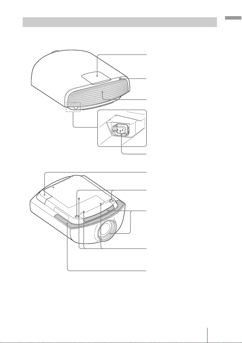
Rear/Bottom
Overview
Lamp cover (1 page 62)
Remote control detector
(1 page 10)
Ventilation holes
(exhaust)
AC IN socket (1 page 7)
AC inlet cover (supplied)
For details on how to attach the
AC inlet cover, see page 7.
Front feet (adjustable) (1 page 14)
Ventilation holes (intake)
Projector suspension
support attaching hole
(1 page 82)
Ventilation holes (intake)
5
Page 6
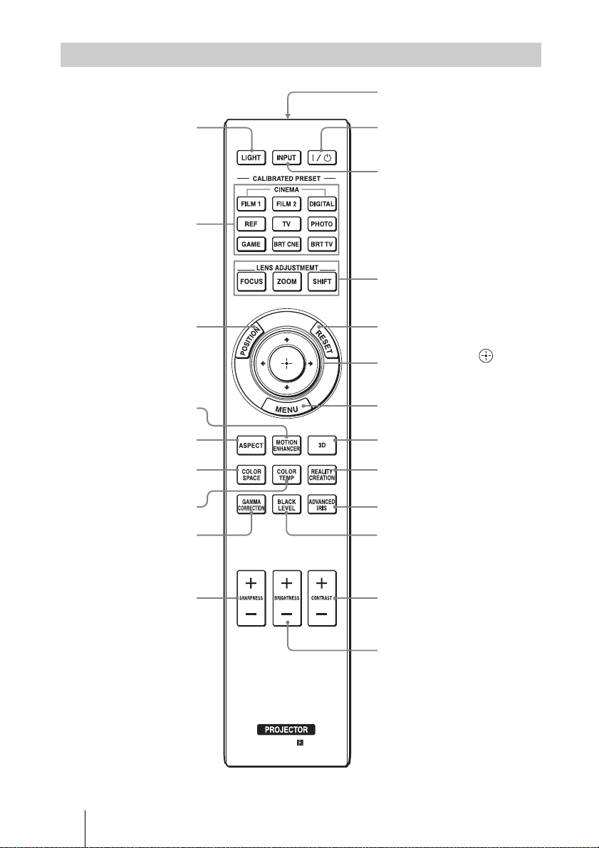
Remote Control
LIGHT button
Illuminates the buttons on
the remote control.
CALIBRATED PRESET
buttons (1 page 29)
Infrared transmitter
?/1 (ON/STANDBY)
button (1 page 11)
INPUT button (1 page 20)
LENS ADJUSTMENT buttons
(1 page 11)
POSITION button
(1 page 25)
MOTION ENHANCER
button (1 page 35)
ASPECT button
(1 page 26)
COLOR SPACE button
(1 page 37)
COLOR TEMP button
(1 page 35)
GAMMA CORRECTION
button (1 page 37)
SHARPNESS +/– button
(1 page 35)
RESET button (1 page 32)
M/m/</, (arrow)/ (enter)
buttons (1 page 31)
MENU button (1 page 31)
3D button (1 page 23)
REALITY CREATION button
(1 page 34)
ADVANCED IRIS button
(1 page 34)
BLACK LEVEL button
(1 page 36)
CONTRAST +/– button
(1 page 35)
BRIGHTNESS +/– button
(1 page 35)
6
Page 7

Preparation
This section describes how to install the unit and screen, how to connect the equipment
from which you want to project the picture, etc.
3 Attach the AC inlet cover to the
Connecting the AC Power Cord
unit.
AC inlet cover (supplied)
1 Plug the AC power cord into the
AC IN socket, then attach the
plug holder to the AC power
cord.
AC power cord
(supplied)
AC IN socket
Plug holder
(supplied)
2 Slide the plug holder over the
AC power cord to fix to the unit.
Preparation
7
Page 8
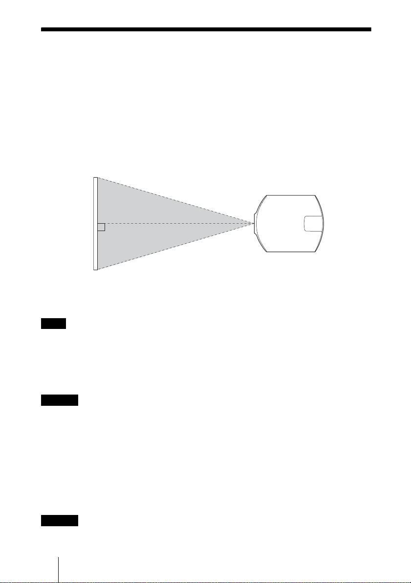
Installing the Unit
The lens shift allows you to have broader options for placing the unit and viewing pictures
easily.
The installation distance between the unit and a screen varies depending on the size of the
screen or whether or not you use the lens shift features. Install this unit so that it fits the
size of your screen. For details on the distance between the unit and the screen (the
projection distance) and the size of projected video, see “Projection Distance and Lens
Shift Range” (1 page 77).
1 Position the unit so that the lens is parallel to the screen.
Top view
Screen
2 Project an image on the screen and adjust the picture so that it fits the
screen (1 page 10).
Note
When using a screen with an uneven surface, stripes pattern may rarely appear on the screen
depending on the distance between the screen and the unit or the zooming magnifications. This is
not a malfunction of the unit.
When installing the unit on the ceiling
Caution
Do not mount the projector on the ceiling or move it by yourself. Be sure to consult with
qualified Sony personnel (charged).
To dealers
Use the Sony PSS-H10 Projector Suspension Support, and take measures to prevent
falling using wire, etc.
For details, refer to the installation manual for dealers of the PSS-H10.
When installing the unit on a wall
Caution
If the wall is not strong enough or the unit is not attached properly, the unit may fall and
cause injury.
8
Page 9

There is a possibility of spoiling the performance of the unit significantly, depending on
the installation position.
Do not mount the projector on the wall or move it by yourself. Be sure to consult with
qualified Sony personnel.
Preparation
9
Page 10
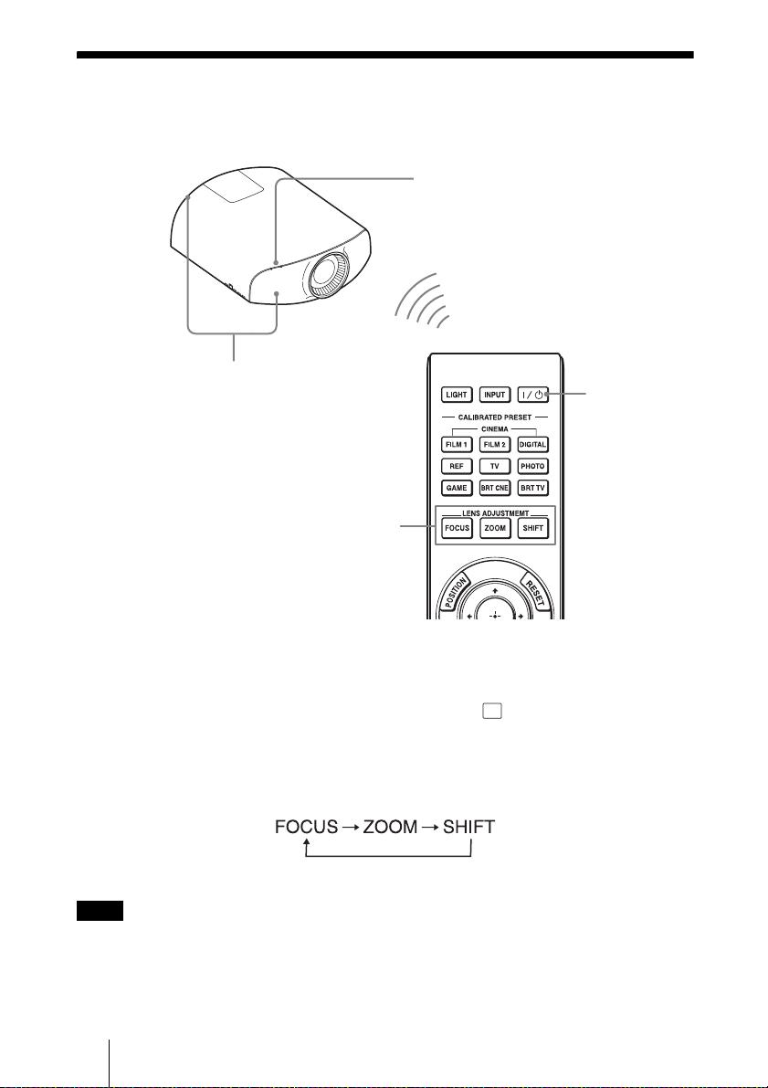
Adjusting the Picture Position
Project an image on the screen and then adjust the picture position.
ON/STANDBY indicator
1
Remote control detector
3, 4, 5
LENS
ADJUSTMENT
buttons
2
?/1 (ON/
STANDBY)
button
Tips
?/1 (ON/STANDBY), INPUT, MENU, and M/m/</,/ (joystick) buttons on the side
•The
panel of the unit function the same as those on the remote control. The LENS button functions in
the same way as the LENS ADJUSTMENT (FOCUS, ZOOM, SHIFT) buttons of the remote
control.
• When adjusting the lens, each time you press the LENS button on the unit, the lens adjustment
function switches between “Lens Focus,” “Lens Zoom” and “Lens Shift.”
Note
Depending on the installation location of the unit, you may not control it with the remote control. In
this case, point the remote control at the remote control detector of the unit or the screen.
10
Page 11
1 After connecting the AC power
cord to the unit, plug the AC
power cord into a wall outlet.
The ON/STANDBY indicator lights in
red and the unit goes into standby mode.
Lights in red.
2 Press the ?/1 (ON/STANDBY)
button to turn on the unit.
Preparation
Tip
When “Lens Control” is set to “Off” on the
Installation menu, you cannot adjust the
focus, the picture size or the proper position by
pressing the FO CUS, ZOOM or SHIFT butt ons
(1 page 45).
When “Test Pattern” is set to “Off” on the
Function menu, the test pattern is not
displayed (1 page 44).
The ON/STANDBY indicator flashes in
green, and then lights in green.
Flashes in green for
tens of seconds and
then lights in green.
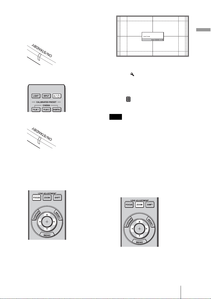
3 Adjust the focus.
Press the LENS ADJUSTMENT
(FOCUS) button to display the Lens
Focus adjustment window (test pattern).
Then adjust the focus of the picture by
pressing the M/m/</, buttons.
Note
Adjust the lens by using buttons on the remote
control or the control panel of the unit. Never
make adjustments by directly turning the lens
with your hands, which may cause damage or
malfunction to the unit.
4 Adjust the picture size.
Press the LENS ADJUSTMENT
(ZOOM) button to display the Lens
Zoom adjustment window (test pattern).
Then adjust the size of the picture by
pressing the M/m/</, buttons.
To make the picture larger, press M/,.
To make the picture smaller, press m/
<.
11
Page 12
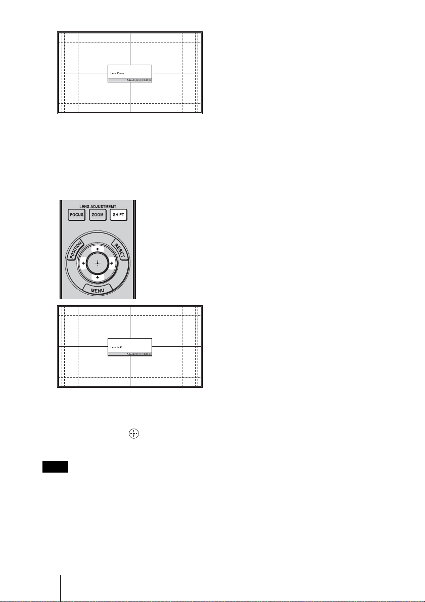
5 Adjust the picture position.
Press the LENS ADJUSTMENT
(SHIFT) button to display the Lens Shift
adjustment window (test pattern). Then
adjust to the proper position of the
picture by pressing the M/m/</,
buttons.
Tip
The test pattern disappears when no operation
has been performed for one minute.
Whenever you press the button, the test
pattern disappears.
Note
When adjusting the window position, do not
touch the lens unit, otherwise your fingers may
be pinched by the moving parts.
12
Page 13
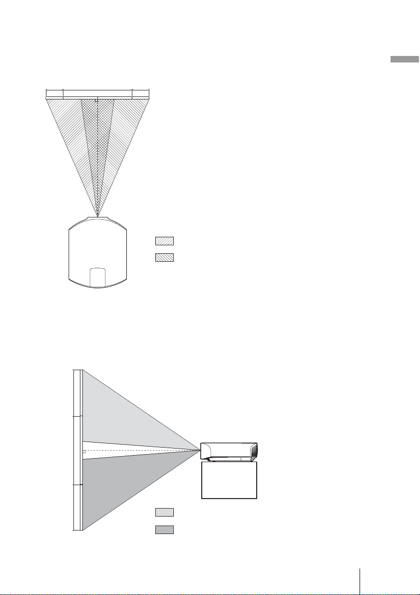
To adjust the horizontal position
Press </,.
The picture projected on the screen moves right or left by a maximum of 31% of the screen
width from the center of the lens.
31% 1 screen width 31%
Top view
: Picture position when moving the picture to the left
at maximum
: Picture position when moving the picture to the
right at maximum
To adjust the vertical position
Press M/m.
The picture projected on the screen moves up or down by a maximum of 80% of the screen
height from the center of the lens.
Side view
Preparation
80%
1 screen
height
80%
: Picture position when moving the picture upward at
maximum
: Picture position when moving the picture downward at
maximum
13
Page 14
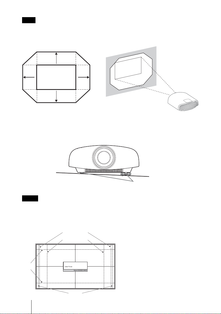
Note
The range to move the picture projected on the screen can be adjusted only within the octagon area
illustrated below. For details, see “Projection Distance and Lens Shift Range” (1 page 77).
Range of movement of
the projected picture
0.8V
Projected Picture
0.31H 0.31H
0.8V
H: Width of the projected picture
V: Height of the projected picture
To adjust the tilt of the installation surface
If the unit is installed on an uneven surface, use the front feet (adjustable) to keep the unit
level.
Turn to adjust.
Front feet (adjustable)
Notes
• If the unit is tilted up or down, the projected image may be trapezoidal.
• Be careful not to catch your finger when turning the front feet (adjustable).
Lens adjustment window (test pattern)
1.78:1 (16:9)
1.33:1 (4:3)
The dashed lines show the screen sizes of
each aspect ratio.
2.35:1
1.85:1
14
Page 15
Connecting the Unit
When making connections, be sure to do the following:
• Turn off all equipment before making any connections.
• Use the proper cables for each connection.
• Insert the cable plugs properly; poor connection at the plugs may cause a malfunction or
poor picture quality. When pulling out a cable, be sure to pull it out from the plug, not
the cable itself.
• Do not use connecting cables excessively bent, or place heavy objects on them.
• Refer to the operating instructions of the connected equipment.
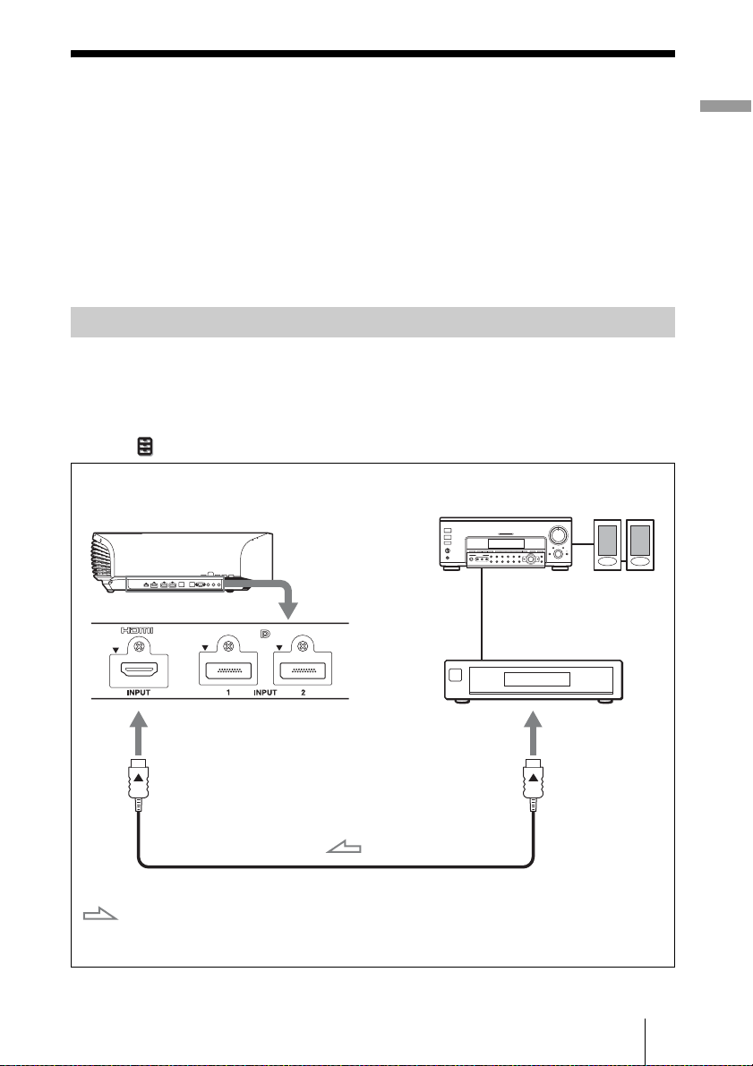
Connecting to a VCR
To connect to equipment with HDMI output connectors
Connect to a Blue-ray disc player/recorder or PS3® equipped with HDMI output. If you
have a Control for HDMI compatible equipment, you can operate the unit synchronizing
with the Control for HDMI compatible equipment. For details, see “HDMI Setting” of the
Function menu (1 page 43) and “About the Control for HDMI” (1 page 55).
Right side of the unit
AV amplifier
Equipment with HDMI output
connectors
Speakers
Preparation
: Video signal flow
to HDMI output
HDMI cable (not supplied)
When using an optional HDMI cable, be sure to use a Sony
HDMI cable or other cable that has the HDMI logo.
15
Page 16
Notes
• Use a high-speed HDMI cable. With a standard HDMI cable, images of 1080p, DeepColor, 3D
video and 4K video may not be displayed properly.
• When connecting an HDMI cable to the unit, make sure the
input of the unit and the
• If the picture from equipment connected to the unit with an HDMI cable is not correct, check the
settings of the connected equipment.
v mark on the connector of the cable is set at the same position.
V mark on the upper part of the HDMI
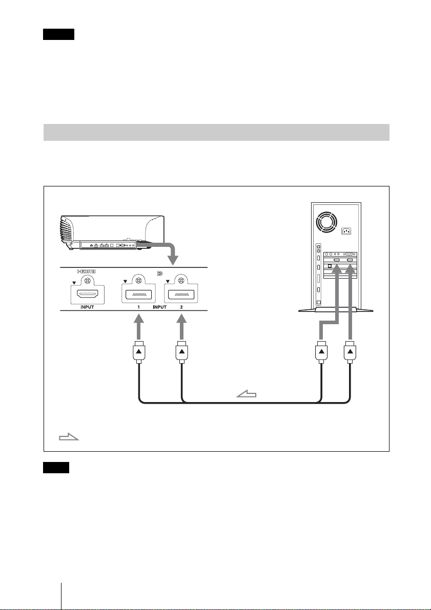
Connecting to a workstation (V Split display connection)
When connecting two DisplayPort cables to project a “4096 × 2160” or “3840 × 2160”
high resolution picture, connect DisplayPort output 1 and DisplayPort output 2 of the
workstation to DisplayPort input 1 and DisplayPort input 2 of the unit respectively.
Workstation
Right side of the unit
DisplayPort output
DisplayPort cables (not supplied)
: Video signal flow
Note
If no picture is projected with the workstation connected to the unit with DisplayPort cables, check
the settings of the workstation, or graphic boards.
16
Page 17
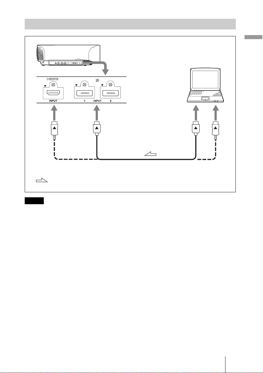
Connecting to a Computer
Right side of the unit
Computer
to monitor output
DisplayPort cable (not supplied) or HDMI cable (not supplied)
: Video signal flow
Notes
When using an optional HDMI cable, be sure to use a Sony
HDMI cable or other cable that has the HDMI logo.
• Use a high-speed HDMI cable. With a standard HDMI cable, images of 1080p video may not be
displayed properly.
• When connecting an HDMI cable, make sure the
V mark on the upper part of the HDMI input of
the unit and the v mark on the connector of the cable is set at the same position.
• If you set your computer, such as a notebook type, to output the signal to both computer’s display
and this equipment, the picture of the equipment may not appear properly. Set your computer to
output the signal to only the external monitor.
For details, refer to the computer’s operating instructions supplied with your computer. For
settings of the computer, consult with the manufacturer of the computer.
• If the picture from equipment connected to the unit with an HDMI or DisplayPort cable is not
correct, check the settings of the connected equipment.
Preparation
17
Page 18
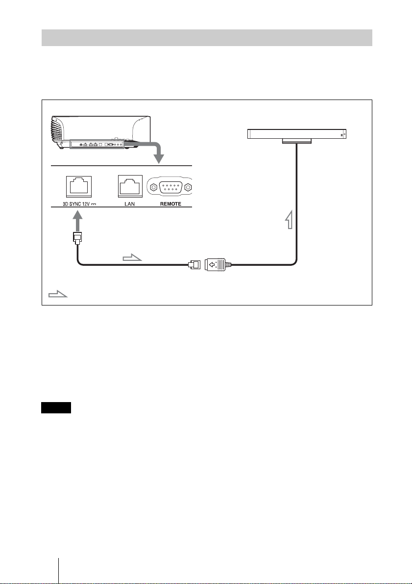
Connecting to a 3D Sync Transmitter
This unit incorporates a 3D Sync Transmitter. Depending on the installation environment
of the unit, the 3D glasses may not receive 3D signals properly from the unit’s built-in 3D
Sync Transmitter. In this case, connect an optional 3D Sync Transmitter and place it near
your viewing position.
Right side of the unit
3D Sync Transmitter (not supplied)
LAN cable (not supplied)
: 3D sync signal flow
Tip
Place the optional 3D Sync Transmitter directly facing the 3D glasses. Also, in order to stabilize
operation of the 3D glasses, it is recommended that you place the 3D Sync Transmitter near your
viewing position.
CAUTION
Be sure to use straight-type LAN cable of up to 15 m labeled TYPE CM, and do not use
an extension cord.
Notes
• The 3D SYNC connector is dedicated for the optional 3D Sync Transmitter. Do not connect
computers or other network devices, to avoid malfunction.
• You can use a 3D Sync Transmitter separate from this unit, using an optional LAN cable (straighttype).
If the usage environment has interference of a continuous specific frequency, synchronization of
3D image signals and the 3D glasses may be lost. In this case, use a LAN cable labeled Category 7.
When watching 3D images in an environment that has even more interference, use the internal
transmitter.
• Be sure to use cable of up to 15 m, and do not use an extension cord. Also, keep the LAN cable
away from any AC power cords as much as possible.
• Only one 3D Sync Transmitter should be connected to the unit. Connecting multiple 3D Sync
Transmitters may cause a malfunction.
18
Page 19
• When connected to the 3D Sync Transmitter, the built-in 3D Sync Transmitter feature of the unit
will turn off. You cannot use both at the same time.
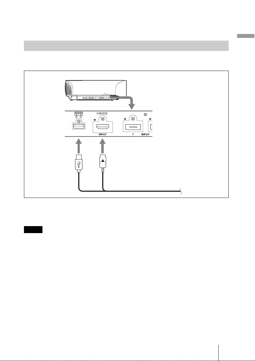
Connecting a USB cable
If using a commercial optical fiber HDMI cable, etc., which needs a power supply, use a
USB cable to supply the power.
Right side of the unit
Optical fiber HDMI cable with connector for
USB power supply (not supplied)
Tips
• For details on the output specification of a USB connector, see “Specifications” (1 page 66).
• Power is not supplied during standby mode.
Preparation
Notes
• The USB connector of this unit is for output only. Do not connect the unit to a USB port of a PC
etc.; it may cause a malfunction.
• Sony is not liable for loss of data or failure of a device arising from a USB connection with the unit.
• Before using, read the manual of the device to be connected.
• Before using, be sure to check the rated voltage and current of the device.
• For safety, if the input current is higher than the rated current, the output voltage of the unit may
temporarily shut down.
19
Page 20
Projecting/Adjusting an Image
This section describes how to operate the unit to view the picture from the equipment
connected to the unit. It also describes how to adjust the quality of the picture.
Projecting the Picture
1 Power on both the unit and the
equipment connected to the
unit.
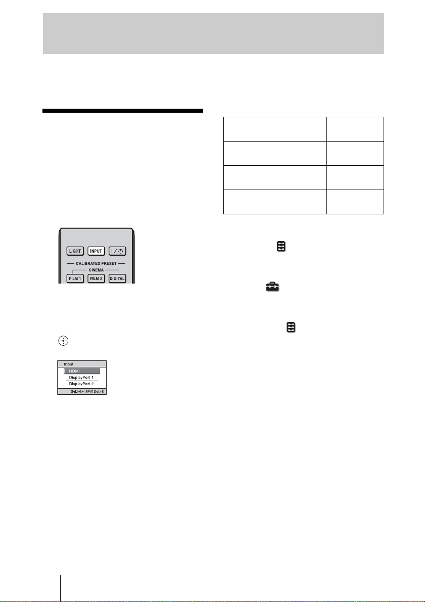
2 Press INPUT to display the input
palette on the screen.
3 Select the equipment from
which you want to display
images.
Press INPUT repeatedly or press M/m/
(enter) to select the equipment from
which to project.
Example: To view the picture from
the video equipment
connected to the HDMI
connector of this unit.
To view the picture from Press INPUT
Equipment connected to the
HDMI connector
Equipment connected to the
DisplayPort 1 connector
Equipment connected to the
DisplayPort 2 connector
Tips
• When “Auto Input Search” is set to “On” on
the Function menu, only input terminals
with effective signals are displayed in the
input palette.
• When “Status” is set to “Off” or “All Off” on
the Setup menu, the input palette does
not appear. Press the INPUT button to switch
between input terminals in sequence.
• When the “Control for HDMI” is set to “On”
on the Function menu, the input terminal
with effective signals is automatically
displayed, synchronizing with the operation
of the equipment connected to HDMI input
of the unit. (Only when the connected
equipment supports Control for HDMI
compatible.)
to display
HDMI
DisplayPort 1
DisplayPort 2
20
Page 21

Turning Off the Power
1 Press the ?/1 (ON/STANDBY)
button.
A message “POWER OFF?” appears on
the screen.
2 Press the ?/1 (ON/STANDBY)
button again before the
message disappears.
The ON/STANDBY indicator flashes in
green and the fan continues to run to
reduce the internal heat. First, the ON/
STANDBY indicator flashes quickly,
during which you will not be able to
light up the ON/STANDBY indicator
with the ?/1 (ON/STANDBY) button.
The fan stops and the ON/STANDBY
indicator changes from flashing green to
remaining red.
The power is turned off completely, and
you can disconnect the AC power cord.
Note
Never disconnect the AC power cord while
the indicator is flashing.
You can turn off the unit by holding the ?/1
(ON/STANDBY) button for about 1 second,
instead of performing the above steps.
Projecting highresolution images (V
Split display)
Signals transferred after an image is split at
“4096 × 2160” or “3840 × 2160” resolution
are projected.
1 Connect DisplayPort output 1
and DisplayPort output 2 of the
workstation to DisplayPort input
1 and DisplayPort input 2 of the
unit respectively (1 page 16).
2 Turn on the unit and
workstation.
Projecting/Adjusting an Image
3 Select DisplayPort 1 (or
DisplayPort 2) in the input
palette.
4 Select either “2048 × 2160” or
“1920 × 2160” resolution in the
setting screen on the
workstation*.
5 Select 60Hz for the refresh rate.
* For information on the setting screen,
as operation differs depending on the
OS or the graphic boards which are
installed in the workstation, consult
with the manufacturer of the
workstation or graphic boards.
If “2048 × 2160” or “1920 × 2160” signals
are input via DisplayPort input 1 and
21
Page 22

DisplayPort input 2, a “4096 × 2160” or
“3840 × 2160” resolution image will be
displayed.
Notes
• During V Split display, setting items on the
Picture menu are adjustment/setting values
stored for the DiplayPort input selected in
step 3 (1 page 74).
• Input the synchronized signals output from
the same signal system in the same signal
format to DisplayPort 1 and DisplayPort 2.
Watching 3D Video Images
You can enjoy powerful 3D video images,
such as from 3D games and 3D Blu-ray
Discs, using the optional 3D glasses.
1 Turn on the HDMI equipment for
3D compatibility connected to
the unit, then play the 3D
content.
For details on how to play 3D content,
refer to the operating instructions for the
connected equipment.
2 Turn on the unit and project the
3D video image onto the screen.
For details on how to project the image,
see “Projecting the Picture” (1 page
20).
3 Turn on the 3D glasses, and
then put them on so that they fit
comfortably.
For details on how to use the 3D glasses,
see “Using the 3D Glasses” (1 page
23).
22
Tips
• The factory default setting for ”2D-3D
Display Sel.” is “Auto” to allow projecting
3D video images automatically when the unit
detects 3D signals.
• To convert 3D video images to 2D video
images, set “2D-3D Display Sel.” to “2D”
(1 page 42).
Notes
• It may not be possible to display 3D video
image, depending on the type of signal. Set
the “2D-3D Display Sel.” to “3D,” and “3D
Format” to “Side-by-Side” or “Over-Under”
to suit the format of the 3D content you want
to watch (1 page 42).
• Use the 3D glasses within the
communication range (1 page 24).
Page 23
• You can watch 3D video images only when
signals from HDMI input. When connecting
3D equipment such as a 3D game or 3D Bluray Disc player to the unit, use an HDMI
cable.
• There are differences in perception of 3D
video images among individuals.
• When the temperature of the usage
environment is low, the 3D effect may be
diminished.
Adjusting/Setting the 3D
functions
You can adjust/set the 3D functions by
pressing the 3D button on the remote control
or with the “3D Settings” of the Function
menu. For details, see “3D Settings” (1
page 42).
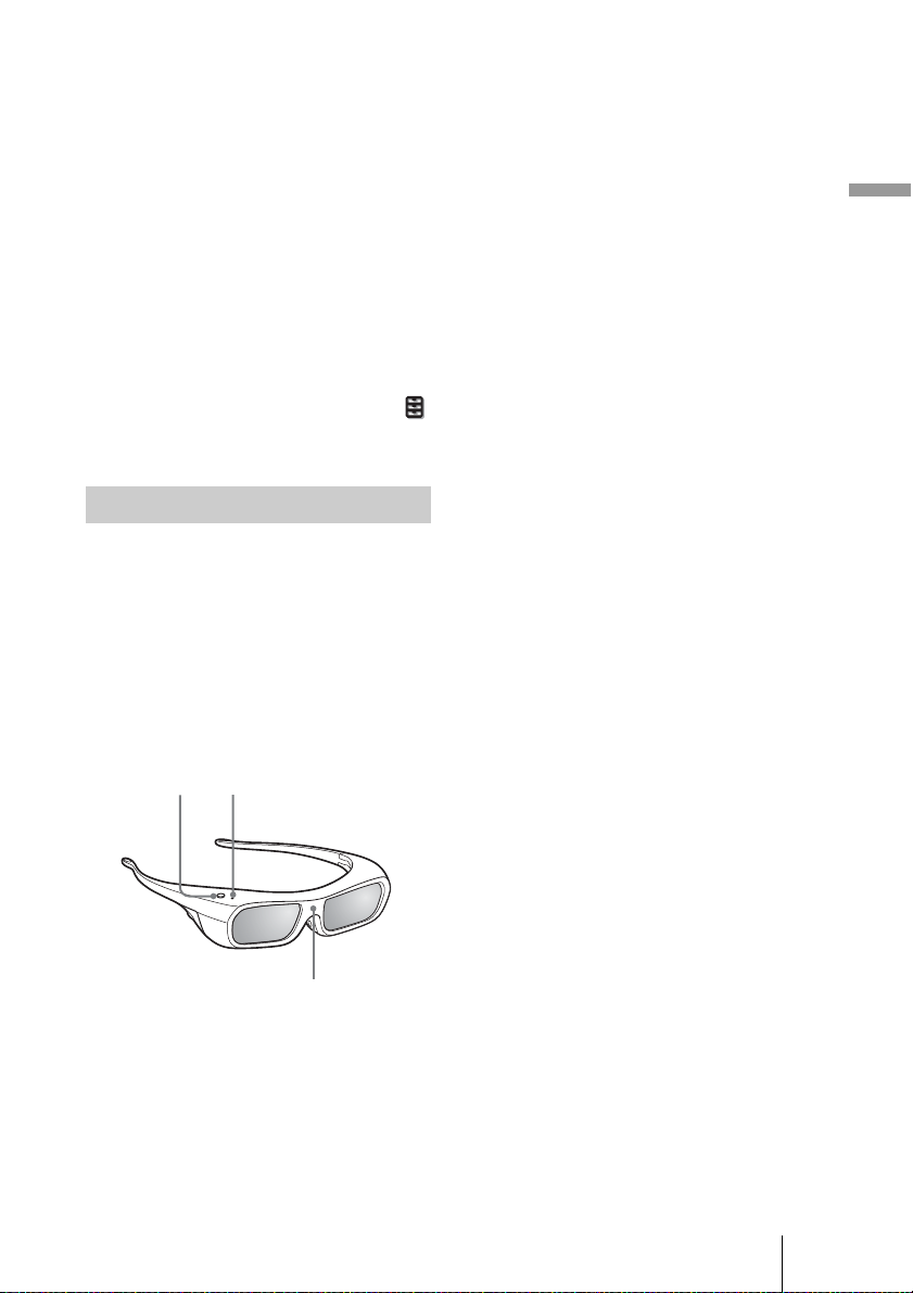
Using the 3D Glasses
The 3D glasses receive signals from the 3D
Sync Transmitter built into the front of the
unit, which are reflected to the glasses from
the screen. When watching 3D video images
using the 3D glasses, face squarely toward
the screen.
Precautions for use
The 3D glasses receive infrared signals sent
by the 3D Sync Transmitter built into the
front of the unit, which are reflected to the
glasses from the screen.
Misoperation may occur if:
– The 3D glasses do not face the screen
– There are objects blocking the path
between the 3D glasses and the screen
– The viewing position is too far from the
screen or the distance between the unit and
screen is too great
– There are other infrared communication
devices nearby
Projecting/Adjusting an Image
1 Press the power button on the
3D glasses.
The LED indicator lights up in green.
LED indicatorPower button
IR sensor
2 Put on the 3D glasses.
3 Turn toward the screen.
23
Page 24
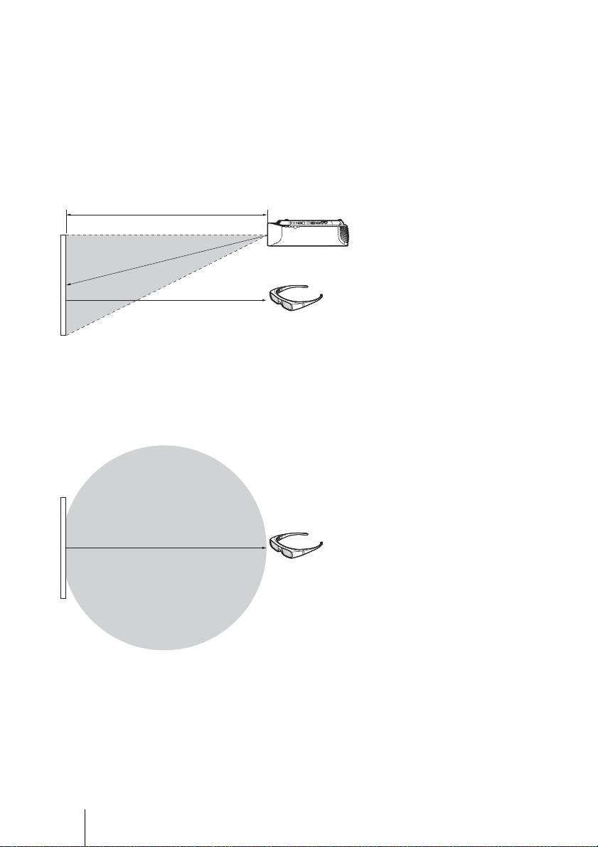
3D glasses communication range
Figures A and B below indicate the communication range of the 3D glasses. If you try to
watch 3D video images from a distance greater than the communication range or install
the unit outside the communication range, the 3D glasses may not be able to display the
images properly. Also, the viable angles and distance vary depending on the screen type,
environment of the room, and installation environment of the unit.
Figure A: 3D sync signal communication distance (Shift Range: 0.5 V)
Side view
a
Projector
b
a + b = 13 m (Maximum)
Screen
3D glasses
Figure B: 3D glasses communication range (The figure shows the distance
between the screen and the projector as 8 m.)
Top or side view
Approx. 5 m (Maximum)
Screen
3D glasses
24
Page 25

Using the Picture Position
You can store up to five combinations of
lens settings (focus, window size, window
position) and aspect ratio, and you can recall
those settings.
1 Press the POSITION button.
Image of the lens moving
In the example below, the images with
aspect ratio of 1.78:1 (16:9) and 2.35:1 are
projected on a 2.35:1 screen.
Projecting/Adjusting an Image
When a 1.78:1 (16:9) image is input
The Picture Position selecting palette is
displayed.
2 Press the POSITION button
repeatedly, or press the M/m/
buttons to select the position.
The settings of the position selected is
recalled.
Store or delete the lens settings and
aspect ratio in the “Picture Position” of
the Screen menu (1 page 38).
A position where lens settings and
aspect ratio are not stored is displayed as
“---.”
When a 2.35:1 image is input
Press the POSITION
button.
The 2.35:1 image expands to
fill the screen.
Notes
• After you have selected and confirmed the
lens position, the lens starts to move. Do not
touch, or place anything near, the lens,
otherwise it may cause injury or a
malfunction.
• If you press any button on the unit while the
lens is moving, the lens stops. In this case,
select the lens position again or adjust the
lens manually.
• The Picture Position function is not
guaranteed to reproduce the lens settings
precisely.
• When you use the subtended screen angle of
two or more aspects using lens zoom, install
the unit within the specified parameters
referring to “Projection distance” (1 page
78). With some setting positions, the range of
lens shift may be restricted, even though the
unit is installed within the specified
parameters.
25
Page 26
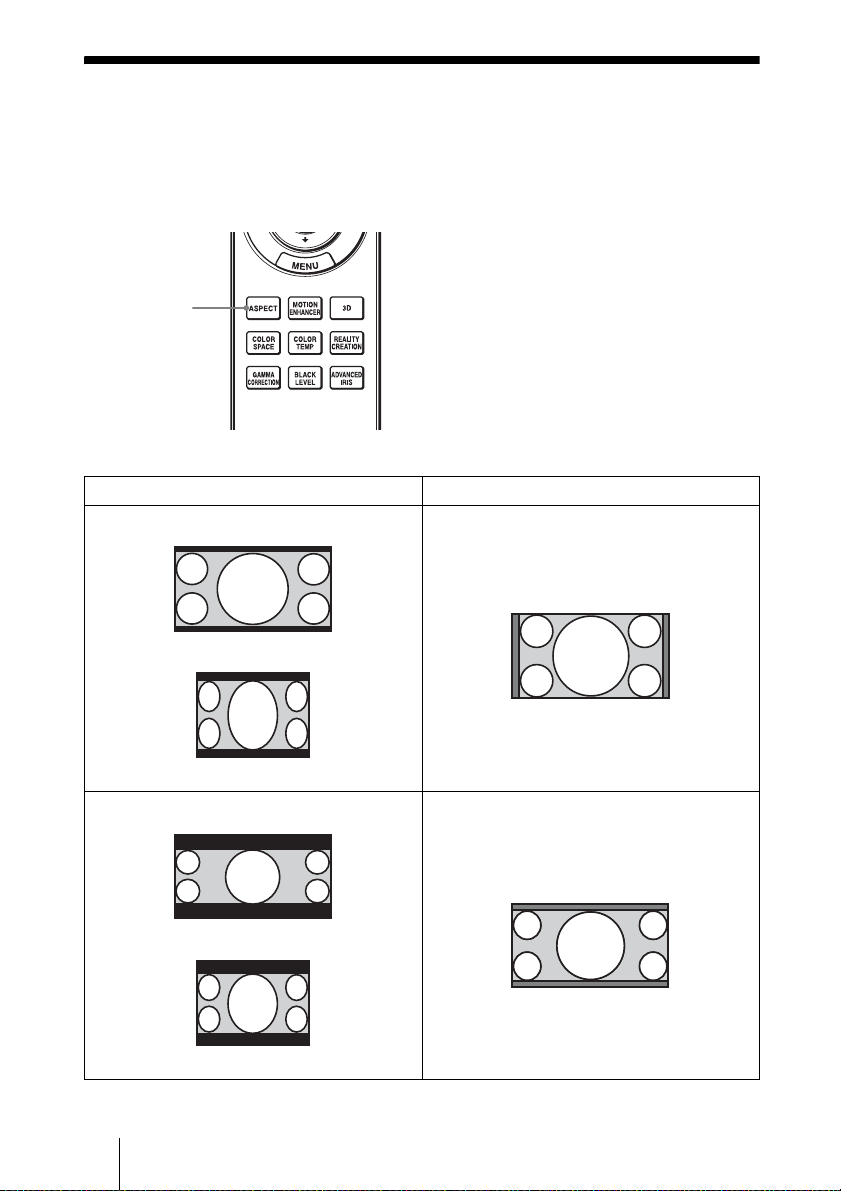
Selecting the Aspect Ratio According to the Video Signal
You can select an aspect ratio best suited for the video signal received.
Press ASPECT.
Each time you press the button, you can
select the “Aspect” setting.
ASPECT
button
Original image Recommended setting and resultant images
1.85:1
You can also select it using the menu
(1 page 39).
1.85:1 Zoom
26
Squeezed 1.85:1
2.35:1 Zoom
2.35:1
Squeezed 2.35:1
Page 27

Original image Recommended setting and resultant images
Normal
1.78:1 (16:9)
1.33:1 (4:3)
1.33:1 (4:3) with side panels
Stretch
Squeezed
Projecting/Adjusting an Image
2.35:1
V Stretch
When using an anamorphic lens
27
Page 28

Original image Recommended setting and resultant images
Squeeze
16:9
When using an anamorphic lens
Notes
• Selectable aspect modes vary depending on the input signal. (1 page 73)
• The aspect cannot be selected for an input signal from a computer, or when preset memory number
76 or 96 (1 page 68) signal is input.
Notes on switching the “Aspect” setting
• Select the aspect mode taking into account that changing the aspect ratio of the original
picture will provide a different look from that of the original image.
• Note that if the unit is used for profit or for public viewing, modifying the original
picture by switching the aspect may constitute an infringement of the rights of authors
or producers, which are legally protected.
28
Page 29

Selecting the Picture Viewing Mode
You can select the picture viewing mode that best suits the type of video source or room
conditions.
You can save and use different preset modes for 2D/3D respectively.
Press one of the CALIBRATED PRESET buttons.
CALIBRATED
PRESET buttons
Setting items Description
CINEMA FILM 1 Picture quality suited to reproducing the highly dynamic and clear images
typical of master positive film.
CINEMA FILM 2 Picture quality suited to reproducing the rich tone and color typical of a
movie theater.
CINEMA DIGITAL Picture quality suited to reproducing digital cinema-like images
resembling DCI specifications (1 page 56).
REF A picture quality setup suitable for when you want to reproduce faithfully
the original image quality, or for enjoying image quality, without any
adjustment.
TV Picture quality suited for watching TV programs, sports, concerts, etc.
PHOTO Ideal for projecting still images taken with a digital camera.
GAME Picture quality suited to gaming, with well-modulated colors and fast
response.
BRT CINE Picture quality suited for watching movies in a bright environment, such
as a living room.
BRT TV Picture quality suited for watching TV programs, sports, concerts, and
other video images in a bright environment, such as a living room.
Projecting/Adjusting an Image
29
Page 30

Using “ImageDirector3” to Adjust the Picture Quality
By using the “ImageDirector3,” you can make the desired gamma correction from a
computer connected to the unit. Connect the REMOTE or LAN connector of the unit with
a computer and start-up “ImageDirector3” on the computer.
For details on how to use “ImageDirector3,” refer to the Help in “ImageDirector3.”
Notes
• You need to install the “ImageDirector3” on a computer beforehand. “ImageDirector3” can be
downloaded from the Sony website.
http://esupport.sony.com/US/p/select-system.pl
http://www.pro.sony.eu/pro/article/projectors-home-cinema-article
• When connecting the REMOTE or LAN connector with a computer, connect while the power of
the computer and the unit is off.
• You cannot adjust the picture quality when “Gamma Correction” in the Picture menu is set to
“Off”.
• When you set “Gamma Correction” in the Picture menu to 1.8, 2.0, 2.1, 2.2, 2.4, or 2.6,
“ImageDirector3” displays Gamma 1, Gamma 2, Gamma 3, Gamma 4, Gamma 5, or Gamma 6,
respectively.
• If you use “ImageDirector3” while a 3D video image is displayed or a 3D signal is input, the image
may be distorted.
30
Page 31

Adjustments and Settings Using a Menu
This section describes how to make various adjustments and settings using the menus.
Operation through the Menus
The unit is equipped with an on-screen menu
for making various adjustments and settings.
If you select an item name followed by an
arrow (B), the next menu window with
setting items appears.
Adjustments and Settings Using a Menu
1 Press MENU.
The menu window appears.
2 Press M/m to select a menu item,
and press , or .
The items that can be set or adjusted
with the selected menu appear. The item
presently selected is shown in white.
3 Press M/m to select an item you
want to set or adjust and press
, or .
The setting items are displayed in a popup menu, in a setting menu, in an
adjustment menu or in the next menu
window.
Pop-up menu
Setting items
31
Page 32

Setting menu
Adjustment menu
Next menu window
Setting items
To reset the picture that has
been adjusted
Select “Reset” from the Picture menu.
When the screen display appears, select
“Yes” using < and press .
All of the following settings are reset to its
factory preset value:
“Reality Creation,” “Cinema Black Pro,”
“Motionflow,” “Contrast,” “Brightness,”
“Color,” “Hue,” “Color Temp.,”
“Sharpness,” and “Expert Setting” on the
Picture
menu
To reset the items that have
been adjusted
Select an item in the menu screen, and
display the pop-up menu, the setting menu,
or the adjustment menu.
Press RESET on the remote control to reset
only the selected settings to its factory preset
value.
4 Make the setting or adjustment
of an item.
When changing the adjustment
level
To increase the value, press M/,.
To decrease the value, press m/<.
Press to store the setting and restore
the original menu screen.
When changing the setting
Press M/m to change the setting.
Press to restore the original screen.
You can restore the original screen using
< depending on the selected item.
To clear the menu
Press MENU.
32
Note
The RESET button on the remote control is
available only when the adjustment menu or
the setting menu is selected.
Page 33

Picture Menu
The Picture menu is used for adjusting the picture.
Note
These items may not be available, depending on the type of input signal. For details, see “Input
Signals and Adjustable/Setting Items” (1 pages 70 to 73 ).
Item names in brackets represent those printed on the remote control.
Adjustments and Settings Using a Menu
Calib. Preset
[CALIBRATED PRESET]
Reset Resets all currently selected Calib. Preset mode settings to their default
You can select the picture viewing mode that best suits the type of
video source or the environment.
You can save and use different preset modes for 2D/3D respectively.
Cinema Film 1: Picture quality suited to reproducing the highly
dynamic and clear images typical of master positive film.
Cinema Film 2: Picture quality suited to reproducing the rich tone and
color typical of a movie theater.
Cinema Digital: Picture quality suited to reproducing digital cinema-
like images resembling DCI specifications (1 page 56).
Reference: A picture quality setup suitable for when you want to
reproduce faithfully the original image quality, or for enjoying image
quality, without any adjustment.
TV: Picture quality suited for watching TV programs, sports, concerts,
etc.
Photo: Ideal for projecting still images taken with a digital camera.
Game: Picture quality suited to gaming, with well-modulated colors and
fast response.
Bright Cinema: Picture quality suited for watching movies in a bright
environment, such as a living room.
Bright TV: Picture quality suited for watching TV programs, sports,
concerts, and other video images in a bright environment, such as a
living room.
Tip
Any adjustments to picture quality settings are saved for each input.
values (1 page 32).
Tip
Reset does not affect settings saved for the Custom 1 to 5 items of
“Color Temp.”
33
Page 34

Reality Creation
[REALITY CREATION]
Cinema Black Pro Advanced Iris [ADVANCED IRIS]
Motionflow Film Projection
Adjusts the detail and noise processing of images. (Super-resolution
function)
On: Applies detail and noise processing effects.
Resolution: When you increase the setting value, the texture and
detail of the picture become sharper.
Noise Filtering: When you increase the setting value, the noise
(picture roughness) becomes less prominent.
Test: On/Off: Changes “On” and “Off” at a certain frequency to
check the effect of “Reality Creation.”
Tip
The display position of status during the test works together with the
“Menu Position” (1 page 40) setting.
Off: The “Reality Creation” function is not applied.
Switches the iris function.
Auto Full: Automatically adjusts to optimize the iris aperture according
to the brightness level of the input source. Moreover, signal
processing, which optimizes gradation expression between the peak
light and dark parts, expresses a large dynamic range. This results in a
bright and high contrast image.
Auto Limited: A lower brightness than Auto Full, making the image
suitable for viewing in a dark room.
Manual: Manually (fixed) adjusts the iris.
Off: Disables the iris (aperture) function.
Lamp Control
Switches the lamp output.
High: Increases the brightness, and projects brighter images.
Low: Decreases the brightness, and enhances blacks by minimizing
brightness.
Tip
Setting “Low” reduces fan noise, while also reducing energy
consumption for longer lamp life.
Reproduces an image similar to that of projected film.
Use this setting as preferred, based on the image content.
Mode 1: Reduces afterimage more than Mode 2.
Mode 2: Reduces afterimage.
Mode 3: Reduces afterimage slightly.
Off: Afterimage reduction effect is reduced, but the picture will become
brighter.
Tips
• Image becomes darker when the afterimage reduction effect is
increased.
• When the preset memory number 6, 8, 11, 13, 14, 93, 94 or 96 signal is
input, you can select only “Mode 3” or “Off.”
34
Page 35

Motionflow Motion Enhancer [MOTION ENHANCER]
Contrast
[CONTRAST]
Brightness
[BRIGHTNESS]
Color Adjusts the color density.
Hue Adjusts the color tone.
Color Temp.
[COLOR TEMP]
Sharpness
[SHARPNESS]
Reproduces fast-moving pictures smoothly without generating
afterimages.
High: Select this for picture quality smoother than “Low.”
Low: Select this for smooth picture quality.
Off: Select this to not apply the motion enhancer function.
Tip
Certain scenes may contain digital signal artifacts. In this case, set this
function to “Off.”
Adjusts the contrast.
Higher values increase the sharpness in images, while lower values
decrease the sharpness.
You can make adjustments by pressing the CONTRAST +/– on the
remote control.
Adjusts the brightness of the picture.
The higher the setting, the brighter the picture. The lower the setting, the
darker the picture.
You can make adjustments by pressing the BRIGHTNESS +/– on the
remote control.
The higher the setting, the greater the intensity. The lower the setting, the
lower the intensity.
The higher the setting, the more greenish the picture becomes. The lower
the setting, the more reddish the picture becomes.
Adjusts the color temperature.
D93: Equivalent to 9,300 K color temperature normally used in TVs.
Gives white colors a blue tint.
D75: Equivalent to 7,500 K color temperature used as an ancillary
standard illuminant.
Gives a neutral tint between “D93” and “D65.”
D65: Equivalent to 6,500 K color temperature used as a standard
illuminant.
Gives white colors a red tint.
DCI: DCI specification (1 page 56) color temperature.
D55: Equivalent to 5,500 K color temperature used as an ancillary
standard illuminant.
Gives white colors an even redder tint.
Custom 1 to 5: Enables you to adjust, set, and store your favorite color
temperature.
The factory default settings are as follows.
Custom 1: Same as “D93” color temperature setting.
Custom 2: Same as “D75” color temperature setting.
Custom 3: Same as “D65” color temperature setting.
Custom 4: Same as “DCI” color temperature setting.
Custom 5: Same as “D55” color temperature setting.
Sharpens the outline of the picture, or reduces the noise.
The higher the setting, the sharper the picture. The lower the setting, the
softer the picture, thus reducing the noise.
You can make adjustments by pressing the SHARPNESS +/– on the
remote control.
Adjustments and Settings Using a Menu
35
Page 36

Expert Setting NR (Noise Reduction)
Reduces the roughness or noise of the picture.
Usually, use to select “Off.”
If the picture is rough or noisy, select a setting from among “Low,”
“Middle” or “High” according to the input signal source.
MPEG NR (MPEG Noise Reduction)
Reduces block noise and mosquito noise, in particular in digital
signals.
Usually, use to select “Off.”
If the picture is rough or noisy, select a setting from among “Low,”
“Middle” or “High” according to the input signal source.
Smooth Gradation
Smooths the gradation of the flat parts of images.
High/Middle/Low: You can adjust the smooth gradation effect.
Off: The smooth gradation function is not applied.
Film Mode
According to the film source you have selected, make a setting for
playback.
Auto 1: Suitable for reproducing the original picture movement.
Normally, set this to “Auto 1.”
Auto 2: Reproduces a 2-3 or 2-2 Pull-Down format video signal, such as
film sources, in a smooth picture movement. When a video signal
other than 2-3 or 2-2 Pull-Down format is input, the picture is played
back in progressive format.
Off: Plays back the picture in progressive format without detecting
video signals automatically.
Black Level Adj. (Adjust) [BLACK LEVEL]
Emphasizes blacks and strengthens the contrast.
High/Middle/Low: You can adjust the black level.
Off: The black level function is not applied.
36
Page 37

Expert Setting Gamma Correction [GAMMA CORRECTION]
Adjusts the response characteristics of the tone of the picture.
Select a favorite tone from 10 options.
1.8: Bright Produces a brighter picture overall.
2.0
2.1
2.2
2.4
2.6: Dark Produces a darker picture overall.
Gamma 7: Brightens dark areas in the picture, and expands gradation
expression.
Gamma 8: Produces a picture with contrast emphasized slightly.
Gamma 9: Produces a picture with contrast emphasized more than with
Gamma 8.
Gamma 10: Simulates the gamma curve of film.
Off: Gamma Correction is not applied.
Color Correction
On: Optimizes midrange colors, based on the color space setting.
Off: The “Color Correction” effect is not applied.
Clear White
Emphasizes vivid whites.
High/Low: You can adjust the “Clear White” effect.
Off: The “Clear White” effect is not applied.
x.v.Color
Set this item when playing back an x.v.Color video signal.
Set this item to “On” when connecting the unit with equipment that
supports x.v.Color and playing back an x.v.Color video signal.
For details on x.v.Color, see “About the x.v.Color” (1 page 56).
Tip
Setting x.v.Color to “On” disables gamma adjustment.
Color Space [COLOR SPACE]
Converts the color space.
BT.709: An ITU-R BT.709 color space, which is used for high-
definition television broadcast or Blu-ray Disc. The color space is
equivalent to sRGB.
DCI: A color space based on the DCI specification (1 page 56).
Adobe RGB: An approximated Adobe RGB color space, which has a
wider range of color reproduction than sRGB, and suited for
displaying an image recorded in Adobe RGB specification.
Color Space 1: The color space suited for watching TV programs and
video images, such as sport, concerts, etc.
Color Space 2: The color space suited for watching TV programs, sport,
concerts, and other video images in a bright environment, such as a
living room.
Color Space 3: The color space suited for watching movies in a bright
environment, such as a living room.
Adjustments and Settings Using a Menu
37
Page 38

Screen Menu
You can set the input signal, picture size, aspect mode, etc.
.
Note
These items may not be available, depending on the type of input signal. For details, see “Input
Signals and Adjustable/Setting Items” (1 pages 70 to 73).
Item names in brackets represent those printed on the remote control.
Picture Position
[POSITION]
You can store up to five combinations of lens settings (focus, window
size, window position) and aspect ratio.
After setting the lens and aspect, select from “1.85:1,” “2.35:1,”
“Custom 1,” “Custom 2” or “Custom 3” depending on the
subtended screen angle, and after confirming, continue by selecting
“Save,” “Delete,” or “Select.”
Save: Stores the current lens settings in the selected position. If a setting
is already stored in that position, it is overwritten.
Delete: Deletes the stored setting. After the setting is deleted, “1.85:1,”
“2.35:1,” “Custom 1,” “Custom 2,” or “Custom 3” in the display
change to “---.”
Select: Recalls the settings of the selected position.
Tip
The optimal aspect ratio is preset for each picture position. The aspect
ratio can be changed and saved for each picture position.
Notes
• After you have selected and confirmed the lens position, the lens starts
to move. Do not touch the lens and the area around the lens, otherwise
it may cause injury or a malfunction.
• If you press any button on the unit while the lens is moving, the lens
stops. In this case, select the lens position again or adjust the lens
manually.
• When you use a 2.35:1 or a 16:9 subtended screen angle with the
Picture Position function, make sure that the installation position is
suitable (1 page 25).
• The Picture Position function is not guaranteed to reproduce the lens
settings precisely.
38
Page 39

Aspect
[ASPECT]
Over Scan You can select whether or not to display the outline of the picture.
Image Shift Adjusts the horizontal position of the picture.
You can set the aspect ratio of the picture to be displayed for the
current input signal (1 page 26). This item is enabled only when a
video signal (preset memory numbers 5 to 8, 10 to 14, 18 to 20, 74
and 93 to 95)
(1 page 68) is input.
1.85:1 Zoom: A 1.85:1 aspect ratio picture is displayed in its original
aspect ratio, enlarged so that black bands do not appear at the top and
bottom of the screen.
2.35:1 Zoom: A 2.35:1 aspect ratio picture is displayed in its original
aspect ratio, enlarged so that black bands at the top and bottom of the
screen are as small as possible.
When you select “2.35:1 Zoom” from “Trigger Select 1/2” on the
Installation menu, a 12 V signal is output from the TRIGGER 1 or
TRIGGER 2 connector (1 page 45).
Normal: Input video is displayed in its original aspect ratio, enlarged to
fill the screen. This mode is suitable for viewing 1.78:1 (16:9) and
1.33:1 (4:3) video.
Stretch: Displays video that has been squeezed to 1.33:1 (4:3) as 1.78:1
(16:9) aspect ratio.
V Stretch: This is the most suitable mode for using a 2.35:1 screen to
view 2.35:1 video with a commercially available anamorphic lens.
When you select “V Stretch” from “Trigger Select 1/2” on the
Installation menu, a 12 V signal is output from the TRIGGER 1 or
TRIGGER 2 connector (1 page 45).
Squeeze: With this setting, 1.78:1 (16:9) and 1.33:1 (4:3) video will be
displayed in their correct aspect ratios when you use a commercially
available anamorphic lens.
Tips
• When you select “V Stretch” or “Squeeze,” select the anamorphic lens
type from “Anamorphic Lens” in the Installation menu.
• Selectable aspect modes vary depending on the input signal.
• The aspect cannot be selected for an input signal from a computer.
On: Hides the outline of the input picture. Select this setting when noise
appears along the edge of the picture.
Off: Projects the whole of the input picture.
Tip
To display the displayable region within the four directions of the screen,
see “Blanking” on the Installation menu (1 page 46).
Increasing the value moves the picture to the right; decreasing the value
moves the picture to the left.
Tips
• Only “3840 × 2160” resolution images are adjustable.
• When displaying one image with two projectors installed side-by-side,
position both images to align their adjoining edges.
Adjustments and Settings Using a Menu
39
Page 40

Setup Menu
The Setup menu is used to change the factory preset settings, etc.
Status Sets whether or not on-screen messages or menus, etc. are
Language Selects the language used in the menu and on-screen displays.
Menu Position You can change the position to display the menu on the screen.
High Altitude Mode Sets the unit to operate at the prevailing atmospheric pressure.
displayed.
On: Displays on-screen messages and menus.
Off: Turns off the on-screen displays, other than certain menus, a
message when turning off the power, and warning messages.
All Off: Turns off the on-screen displays, other than certain menus,
and a message when turning off the power.
Note
When “All Off” is selected, warning messages for high temperature
or lamp replacement are not displayed.
Note that Sony is not liable for failure of the unit or any accident
caused by selecting “All Off.”
Available languages are: English, Dutch, French, Italian, German,
Spanish, Portuguese, Russian, Swedish, Norwegian, Japanese,
Chinese (Simplified Chinese), Chinese (Traditional Chinese),
Korean, Thai, and Arabic.
Bottom Left: Displays the menu on the bottom left area of the
screen.
Center: Displays the menu on the center of the screen.
On: Use this setting when using the unit at an altitude of 1,500 m or
higher.
Off: Use this setting when using the unit at normal altitudes.
Tip
When this item is set to “On,” the fan noise becomes slightly louder
since the number of fan rotations increases.
40
Page 41

Portrait Mode You can set this mode according to the type of installation.
On: Use this setting for a wall installation (1 page 8).
Off: Use this setting when using the unit horizontally, or ceiling
mounted.
Note
If you use the unit with improper settings, an internal malfunction
may occur.
Standby Mode You can select the power consumption in standby.
Standard: The power consumption in standby mode is normalized.
Low: The power consumption in standby mode is lowered.
Tip
When this item is set to “Low,” the “PJ Auto Power On” function is
disabled (The function is set to “Off” and does not appear in the
menu). The network function is also disabled in standby mode.
Power Saving Sets the power saving mode.
Lamp Cutoff: If no signal is input for 10 minutes, the lamp turns off
automatically and power consumption is reduced. If signal is
resumed, or any button on the control panel or remote control is
pressed, the lamp will light again. In Lamp Cutoff, the ON/
STANDBY indicator lights in orange. (1 page 4)
Standby: If no signal is input for 10 minutes, power is turned off
automatically and the projector goes into standby mode.
Off: The power saving mode is released.
Lamp Setting When replacing the lamps, set the desired lamp setting
(1 page 64).
Adjustments and Settings Using a Menu
41
Page 42

Function Menu
The Function menu is used for changing the settings of the various functions of the unit.
3D Settings You can change the settings of the 3D function.
2D-3D Display Sel.: For Switching the video images to “2D” or
“3D.”
Auto: Displays 3D video images when HDMI signals with 3D
information are input. Displays 2D video images when other
signals are input.
3D: Displays 3D video images according to the 3D system
selected in “3D Format.” However, when HDMI signals with 3D
information are input to the unit, displays 3D video images
according to the 3D system of those HDMI signals.
2D: Displays 2D video images.
* The 3D information is additional information to discriminate
3D. Some HDMI signals have additional information to
discriminate 3D and some HDMI signals have none.
3D Format: Set the 3D system when the input HDMI signals do not
include 3D information.
Simulated 3D: Converts 2D video images to 3D video images.
The setting can be made only for input the HD signals.
• The simulated 3D feature may have limited effect, depending
on the video source.
• There are differences in perception of 3D video images among
individuals.
Side-by-Side: Select this to display 3D images as two similar
images, side-by-side.
Over-Under: Select this to display 3D images as two similar
images, one above the other.
42
Page 43

3D Settings 3D Brightness: For adjusting the brightness of the picture when
watching 3D video images. You can select the brightness “High”
or “Standard.”
3D Depth Adjust: For adjusting the depth of the 3D video images
on the screen. The setting can be made only when a 3D Format
other than “Simulated 3D” is selected.
We recommend that “3D Depth Adjust” be set to “0.” The 3D
video images may be difficult to perceive, depending on the
setting of “3D Depth Adjust.”
Simulated 3D Effect: For adjusting the 3D effect when 2D content
is converted to 3D video images. You can select the effect from
among “High,” “Middle,” and “Low.”
Tips
• “2D-3D Display Sel.” cannot be set to “3D” for some video
sources. For available 3D signals, see “Compatible 3D Signals”
(1 page 72).
• The simulated 3D feature may have limited effect, depending on
the screen size (100 to 120 inches recommended) and the video
source.
• There are differences in perception of 3D video images converted
by the simulated 3D function among individuals.
• The menu display has a ghost while a 3D video image is displayed
and is best viewed with the 3D glasses.
HDMI Setting You can change the settings of the Control for HDMI function.
Control for HDMI: Selects the function whether to turn the Control
for HDMI function effective when the HDMI connector is
connected to a Control for HDMI compatible equipment.
When set to “On,” the following are available.
• The operation of the unit and the connected Control for HDMI
compatible equipment will synchronize with each other.
• The Control for HDMI setting of Sony equipment (AV
amplifier, video, etc.), which is compatible with “Control for
HDMI - Easy Setting,”* will also be effective.
Device Auto Power Off: Sets whether to also turn the power of the
connected Control for HDMI compatible equipment off when you
turn the power of the unit off.
When set to “On,” the equipment will synchronize and turn off
when the power of the unit turns off.
PJ Auto Power On: Select whether to link the power of the unit to
the Control for HDMI compatible equipment.
When set to “On,” the power of the unit will automatically turn on
when the power of the connected equipment is turned on or when
making operations such as playback.
Tip
To enable this function, set “Standby Mode” (1 page 41) on the
Setup menu to “Standard,” and then set “PJ Auto Power On” to
“On.” For details, see “About the Control for HDMI” (1 page 55).
Adjustments and Settings Using a Menu
43
Page 44

HDMI Setting Device List: Lists all the Control for HDMI compatible equipment
connected to the unit.
When “Enable” is selected, the Control for HDMI setting of Sony
equipment (AV amplifier, video, etc.), which is compatible with
“Control for HDMI - Easy Setting,”* will also be effective.
* “Control for HDMI - Easy Setting” is a function that makes the
Control for HDMI setting of equipment connected to HDMI input
of the unit effective as well when the Control for HDMI setting of
the unit is effective. Non-Sony equipment is not compatible.
Dynamic Range Sets the video input level when a signal is input to HDMI,
DisplayPort 1 or DisplayPort 2.
Auto: Sets the video input level automatically.
Limited: The video input level is set for signals of 16-235.
Full: The video input level is set for signals of 0-255.
Note
If the video output setting of the connected HDMI or DisplayPort
device is not set correctly, light and dark parts of the video may
appear too light or too dark.
Auto Input Search Enables selection from only the input which has a signal.
When set to “On,” inputs without signals do not appear on the input
palette that appears when you press INPUT. To display all inputs, set
this to “Off” (1 page 20).
Tes t P at te rn Displays a test pattern according to the setting.
On: A test pattern appears on the screen to be used when adjusting
the lens with “Lens Focus,” “Lens Zoom,” and “Lens Shift.”
Off: A test pattern does not appear.
Tip
While the test pattern is displayed, it is only displayed in green to
allow you to adjust the focus easily.
Background Selects the background color of the screen when no signal is
input.
You can select “Black” or “Blue.”
44
Page 45

Installation Menu
The Installation menu is used for changing the installation settings.
Adjustments and Settings Using a Menu
Image Flip Flips the picture on the screen horizontally and/or vertically.
Lens Control Avoids any operation of the lens such as “Lens Focus,” “Lens
Anamorphic Lens Select a setting to match the anamorphic lens conversion ratio.
Trigger Select Switches the output function of the TRIGGER 1/TRIGGER 2
IR Receiver Selects the remote control detectors (IR Receiver) on the front
HV: Flips the picture horizontally and vertically.
H: Flips the picture horizontally.
V: Flips the picture vertically.
Off: The picture does not flip.
Use this item for installation for the backside projection or ceiling
installation.
Zoom,” and “Lens Shift,” by mistake.
On: Enables adjustment of the lens.
Off: Prevents any adjustment of the lens.
1.24x: Select this when you use an anamorphic lens with a
horizontal rate of 1.24×.
1.32x: Select this when you use an anamorphic lens with a
horizontal rate of 1.32×.
connector.
Off: Turns off the TRIGGER connector function.
Power: Outputs 12 V signals from the TRIGGER 1/TRIGGER 2
connectors when the unit is on. The TRIGGER 1/TRIGGER 2
connectors do not output any signals when the unit is in standby.
V Stretch: Works with the “Aspect” setting’s “V Stretch”
(1 page 39) and outputs a 12 V signal from the TRIGGER 1 or
TRIGGER 2 connector.
2.35:1 Zoom: Works with the “Aspect” setting’s “2.35:1 Zoom” (1
page 39) and outputs a 12 V signal from the TRIGGER 1 or
TRIGGER 2 connector.
and rear of the unit.
Front & Rear: Activates both the front and rear detectors.
Front: Activates the front detector only.
Rear: Activates the rear detector only.
45
Page 46

Blanking This feature allows you to adjust the displayable region within
the four directions of the screen.
Select the edge to adjust by highlighting Left, Right, Top, or Bottom
using the M/m buttons.
Adjust the amount of blanking using the </, buttons.
Tip
Depending on the aspect ratio setting, right/left blanking may not be
available.
46
Page 47

Panel Alignment This feature allows you to adjust the gaps in the color of
characters or the picture.
When set to “On,” “Adjust Color” and “Pattern Color” can be
assigned and adjusted.
Adjust Item: Selects how to make adjustments from below.
Shift: Shifts the whole picture and makes adjustments.
Zone: Selects the desired range and makes adjustments.
Adjust Color: Assigns the desired color to adjust the gaps in color.
Select “R” (Red) or “B” (Blue) to make adjustments based on
“G” (Green).
Pattern Color: Select “R/G” (Red and Green) or “R/G/B” (White,
all colors) when “Adjust Color” is “R” (Red). Select “B/G” (Blue
and Green) or “R/G/B” (White, all colors) when the “Adjust
Color” is “B” (Blue).
Adjust: The shift adjustment and zone adjustment of the color
selected in “Adjust Color” can be made with </,, M/m
buttons.
When “Shift” is selected: Assign the settings of the horizontal
direction (H) with </, buttons and the vertical direction (V)
with M/m buttons on the shift adjustment screen.
When “Zone” is selected: Select the position to adjust with
</, buttons for the horizontal position (H position) and M/m
buttons for the vertical position (V position), then press .
Adjustments and Settings Using a Menu
Set the amount to adjust with </, buttons for the horizontal
direction (H direction) and with M/m buttons for the vertical
direction (V direction). You can select the position to adjust again by
pressing .
Reset: Returns to the factory settings.
Note
Depending on the adjustments made above, colors may become
uneven or the resolution may change.
47
Page 48

Network Setting Perform internet protocol settings.
Set this when accessing from a computer (1 page 50) or using the
supplied gamma control adjustment software “ImageDirector3.”
IP Address Setup: Select the IP address setting method.
Auto (DHCP): The IP address is assigned automatically from the
DHCP server such as a router.
Manual: Specify the IP address manually.
When “Manual” is selected for “IP Address Setup,” select the item
with the </, buttons and input the value with the M/m buttons.
When all items are entered, select “Apply,” and then press the
button. The entered settings will be registered.
IP Address: Set the unit’s IP address. (1.0.0.0 – 223.255.255.255)
Subnet Mask: Set the unit’s subnet mask. (1.0.0.0 –
255.255.255.255)
Default Gateway: Set the unit’s default gateway. (1.0.0.0 –
223.255.255.255)
Primary DNS: Set the primary DNS server. (1.0.0.0 –
223.255.255.255)
Secondary DNS: Set the secondary DNS server. (1.0.0.0 –
223.255.255.255)
MAC Address: Display the unit’s MAC address. This cannot be
changed.
48
Page 49

Information Menu
The Information menu displays the model name, serial number, and the cumulated hours
of usage of the lamp.
Model name: VPL-GT100
Serial No.
Memory No.
Signal type
Model name Displays the model name (VPL-GT100).
Serial No. Displays the serial number.
Memory No. Displays the preset memory number of the input signal.
Signal type Displays the type of the input signal. When input signals with 3D
information are input, the type of input signals and the 3D format are
displayed.
Lamp Timer Indicates how long the lamp has been turned on (total usage).
Note
You cannot adjust or change the displays listed above.
About the Preset Memory No.
This unit has 25 types of preset data for input signals (the preset memory). When the preset
signal is input, the unit automatically detects the signal type and recalls the data for the
signal from the preset memory to adjust it to an optimum picture. The memory number
and signal type of that signal are displayed in the Information menu.
For information on the preset signals, see the table “Preset Signals.” (1 page 68)
Note
Depending on the computer input signal, parts of screen may be hidden or displayed incorrectly.
Adjustments and Settings Using a Menu
49
Page 50

Network
Using Network Features
Connection to the network allows you to operate the following features:
• Checking the current status of the unit via a Web browser.
• Remotely controlling the unit via a Web browser.
• Receiving the e-mail report for the unit.
• Making the network settings for the unit.
• Supports network monitoring and control protocol (Advertisement, PJ Talk, SNMP,
AMX DDDP [Dynamic Device Discovery Protocol]).
• Using the gamma control software “ImageDirector3.”
Notes
• The menu displays used for the explanation below may be different depending on the model you
are using.
• Supported Web browsers are Internet Explorer 6/7/8/9.
• The menu displays only English.
• If the browser of your computer is set to [Use a proxy server] when you have access to the unit
from your computer, click the check mark to set accessing without using a proxy server.
50
Page 51

Displaying the Control Window of the Unit with a Web Browser
1 Connect the LAN cable.
LAN cable
(straight type)
(not supplied)
Hub, router, etc.
2 Set the network settings for the
unit using “Network Setting” on
the Installation menu (1
page 48).
3 Start a web browser on the
computer, enter the following in
the address field, then press the
Enter key on your computer.
http://xxx.xxx.xxx.xxx
(xxx.xxx.xxx.xxx: IP address for the
unit)
You can confirm the IP address of the
unit under “Network Setting” on the
Installation menu.
LAN Connector
Once you make the network settings,
you can open the Control window only
by performing step 3 of this procedure.
Network
The following window appears in the
Web browser:
51
Page 52

Operating the Control Window
Switching the Page
Click one of the Page Switching buttons to
display the desired setting page.
Page Switching buttons
Note
If you forget your password, consult with
qualified Sony personnel.
Confirming the Information Regarding the Unit
You can confirm the current settings for the
unit on the Information page.
Setting the Access Limitation
You can limit a user for accessing any
particular page.
Administrator: Allowed access to all
pages
User: Allowed access to all pages
except the Setup page
Set under [Password] of the Setup page.
When you access the Setup page for the first
time, enter “root” for user name and enter
nothing for password.
The name of the administrator is preset to
“root.”
Entry area for [Administrator]
Entry area for [User]
When you change the password, input a new
password after deleting the password
(*****) that was set.
Information area
Operating the Unit from a Computer
You can control the unit from the computer
on the Control page.
Operation area
The functions of the buttons shown in the
operation area are the same as those of the
buttons on the supplied remote control.
52
Page 53

Using the E-mail Report Function
Mail Report button
Set the e-mail report function on the Setup
page.
Entered values will not be applied unless
you click on [Apply].
1 Click on [Owner information] to
enter the owner information
recorded in the
Owner information button
e-mail report.
1
2 Set the timing of the e-mail
report.
Click on [Mail Report] to open the Mail
Report page.
Lamp Reminder (Lamp1): Set the
timing for lamp replacement.
Maintenance Reminder: Set the timing
for maintenance.
Tip
Check the RESET check box and then
click on [Apply] to reset the value of
Elapsed Hours.
2
3
4
6
5
3 Enter the outgoing e-mail
address in the Email Address
box, then check the Report
Timing check box of the e-mail
report to be sent.
4 Set the mail account for sending
e-mail reports.
Mail Address: Enter the e-mail address.
Outgoing Mail Server (SMTP): Enter
the address of outgoing mail server
(SMTP).
Required Authentication: Check this
check box if authentication is required
for sending e-mail.
Requires the use of POP
Authentication before send email
(POP before SMTP): Check this
check box to arrange for POP
authentication to be performed before
sending e-mail.
Incoming Mail Server (POP3): Enter
the address of the incoming-mail
server (POP3) to be used for POP
authentication.
Account Name: Enter the mail account.
Password: Enter the password.
Network
53
Page 54

SMTP Authentication: Check this
check box to arrange for SMTP
authentication to be performed before
sending e-mail.
Account Name: Enter the mail account.
Password: Enter the password.
5 Confirm the contents of the e-
mail report.
When you click on [View], the contents
of the e-mail report are displayed.
6 Send the test mail.
Check on the Send test mail check box,
then click on [Apply] to send your test
mail to the e-mail address you set.
Notes
• You cannot use the e-mail report function
because Outbound Port 25 Blocking on the
network is preventing a connection to the
SMTP server.
• You cannot enter the following characters in
the text box: ', ", \, &, <, >
54
Page 55

Others
This section describes about the other functions, how to solve the problems, how to
replace the lamp, etc.
page 43. For settings of the Control for
About the Control for HDMI
What is the Control for HDMI?
Control for HDMI is an HDMI standard
mutual control function which uses the
HDMI CEC (Consumer Electronics
Control) specification. By connecting a
variety of Control for HDMI compatible
equipment such as a hard disk Blu-ray Disc
player, a DVD player/recorder, an AV
amplifier, etc. to a Sony Control for HDMI
compatible TV or a projector with an HDMI
cable, the equipment connected will
synchronize with the TV or the projector
when either is operated.
Using the Control for HDMI
function
• Connect and assign the settings of each
equipment appropriately.
• Do not turn off the main power of the
equipment.
• Set the input setting of the projector to the
HDMI input which the equipment is
connected.
• Check if the picture from the equipment
appears appropriately on the projector.
Connecting a Control for HDMI
compatible equipment
Use an HDMI cable to connect the projector
and the Control for HDMI compatible
equipment. Use a cable that has acquired the
HDMI logo.
HDMI compatible equipment connected to
the projector, refer to its operating
instructions. When equipment that is
compatible with the “Control for HDMI Easy Setting” is connected to the HDMI
input of the projector, if you turn the Control
for HDMI function setting of the projector
on, the Control for HDMI function setting of
the connected equipment will also turn on.
What you can do with the
Control for HDMI
• By turning on or playing back the
connected equipment, the projector will
turn on and the input setting will switch to
the terminal of the connected equipment
automatically.
• By turning the power of the projector off,
the power of the connected equipment will
also turn off automatically.
• By changing the language setting of the
projector, the language setting of the
connected equipment will also change to
the same language automatically.
Notes
• The available functions of the Control for
HDMI differ depending on each equipment.
Refer to the operating instruction of each
equipment.
• Some synchronization may be available with
equipment of other brands with similar
functions, but it is not guaranteed.
Others
Setting the Control for HDMI
Be sure to assign the appropriate settings for
both the projector and the Control for HDMI
compatible equipment connected to the
projector. For settings of the projector, see
55
Page 56

About DCI specification
DCI is a specification for Digital cinema
projection systems, established by the
industry standards body DCI (Digital
Cinema Initiatives), an affiliation of six
major Hollywood studios.
About the x.v.Color
• “x.v.Color” is a promotion name given to
the products that have the capability to
realize a wide color space based on the
xvYCC specifications and is a trademark
of Sony Corporation.
• xvYCC is an international standard of the
technical specifications of the extendedgamut color space for video signals. The
color gamut of xvYCC is wider than the
one of sRGB that is used with the current
television system.
• Note that if the unit is used for profit or for
public viewing, displaying 2D video
images as 3D video images by converting
to the simulated 3D may constitute an
infringement of the rights of authors or
producers, which are legally protected.
About HDCP
HDCP (High-Bandwidth Digital Content
Protection) is the copyright protection
technology which enciphers the digital
signal transmitted and received via a HDMI
terminal or a DisplayPort terminal, and
prevents unauthorized copying.
As the HDMI input and DisplayPort input of
this unit are compliant with HDCP, a digital
image which is protected by HDCP
technology can be projected.
About the simulated 3D feature
• Use the simulated 3D function taking into
account that the picture will provide a
different look from the original images,
because this function converts the video
images.
56
Page 57

Troubleshooting
If the unit appears to be operating erratically, try to diagnose and correct the problem using
the following instructions. If the problem persists, consult with qualified Sony personnel.
Power
Symptom Cause and Remedy
The power is not turned on. c The power may not turn on if you turn the power off with
The power is suddenly
turned off.
(ON/STANDBY) button and turn it on again in a short time.
After about 1 minute, turn the power on.
c Close the lamp door (inner cover) securely, then tighten the
screws securely (1 page 63).
c Check warning indicators (1 page 60).
c Check that “Power Saving” in the Setup menu is set to
“Standby.” (1 page 41)
c Set “Power Saving” to “Off.”
Picture
Symptom Cause and Remedy
No picture. c Check that the connecting cable is connected to the external
The picture has ghosts. c Video images are displayed in 3D. Watch the 3D video images
Bright or dark area of the
video appears too bright or
too dark.
The picture is too dark. c Adjust “Contrast” or “Brightness” on the Picture menu
The picture is not clear. c Adjust the focus (1 page 11).
The color of characters or
the picture is not
appropriate.
equipment properly (1 page 15).
c Select the input source correctly using the INPUT button
(1 page 20).
c Check that the computer signal is set for output to an external
monitor.
c If the notebook computer, etc., signal is output to its display and
an external monitor, the external monitor’s image may not be
displayed correctly. Set your computer to output the signal to
only an external monitor.
using the 3D glasses, and set “2D-3D Display Sel.” to “3D” (1
page 42).
c This symptom may occur when signal level other than those of
HDMI standard is input. Switch the output level of the
connected equipment, or switch the Dynamic Range of the unit
(1 page 44).
properly (1 page 35).
c Condensation has accumulated on the lens. Leave the unit for
about 2 hours with the power on.
c Select the desired color registration in “Panel Alignment” of the
Installation menu (1 page 47).
?/1
Others
57
Page 58

Symptom Cause and Remedy
Image is left on the screen.
(image retention)
c When high contrast non-moving images are displayed for a long
period of time, there may be some image retention on the
screen. This is only a temporary condition. Turning off the
power for a while will eliminate the retained image.
On-screen display
Symptom Cause and Remedy
On-screen display does not
appear.
The model name does not
disappear from the screen.
Input terminals do not
appear.
c Set “Status” on the Setup menu to “On” (1 page 40).
c Check if the ON/STANDBY indicator should light in green.
When the ON/STANDBY indicator blinks in green, the unit is
starting up. Wait until it stops blinking and remains lit in green.
c The display mode of the unit may be set at the time of purchase.
Consult with your local dealer or qualified Sony personnel.
c Set “Auto Input Search” on the Function menu to “Off” (1
page 44).
Remote control
Symptom Cause and Remedy
The remote control does
not work.
c Batteries could be weak. Replace them with new batteries.
c Insert the batteries with the correct polarities.
c If there is a fluorescent lamp near the remote control detector,
the unit may work improperly or inadvertently.
c If you use the optional 3D Sync Transmitter and point it to the
remote control detector of the unit, the remote control may not
work properly.
c Confirm the position of the remote control detector on the unit
(1 page 4).
c Set “IR Receiver” to “Front & Rear” on the Installation
menu (1 page 45).
58
Page 59

3D video images
Symptom Cause and Remedy
The video image does not
seem like 3D video images.
c Check if the 3D glasses are turned on (1 page 23).
c Make sure that the battery in the 3D glasses is charged.
c Check if the input source is HDMI.
c Set “2D-3D Display Sel.” to “Auto” or “3D” (1 page 42).
c Check if the input signals are compatible 3D signals (1 page
72).
c If no 3D signal is input from the 3D equipment connected to the
unit, restarting the connected 3D equipment may solve the
problem.
c When the viewing or projector position is too far from the
screen, the 3D glasses may not be able to display the images
properly (1 page 24).
c If you use the optional 3D Sync Transmitter, check that it is
placed within the specified range (1 page 18).
c The screen size is not appropriate. Set the zooming
magnification to low or watch the image from farther away from
the screen (1 page 78).
Others
Symptom Cause and Remedy
The fan is noisy. c Check the setting of “High Altitude Mode” on the Setup
The lens shift cannot be
adjusted.
The unit and connected
equipment turn On/Off,
play back, and operate at
the same time.
menu (1 page 40).
c Make sure that the room temperature is not too high.
c Check the installation conditions (1 page 8).
The number of fan rotation increases to maintain the product
reliability of the projector’s components in a room, where the
temperature is higher than normal. The fan noise becomes
slightly louder. The approximate normal temperature is 25°C.
c The lens shift cannot be adjusted over the range of movement.
Adjust the lens shift within the range of movement (1
pages 14, 77).
c “Control for HDMI,” “Device Auto Power Off,” and “PJ Auto
Power ON” are set to “On.” Set them to “Off.”
For details, see “HDMI Setting” (1 page 43).
Others
59
Page 60

Warning Indicators
The ON/STANDBY or LAMP/COVER indicator lights up or flashes if there is any
trouble with your projector.
ON/STANDBY indicator
LAMP/COVER indicator
Symptom Cause and Remedy
LAMP/COVER flashes in
red. (A repetition rate of 2
flashes)
LAMP/COVER flashes in
red. (A repetition rate of 3
flashes)
ON/STANDBY flashes in
red. (A repetition rate of 4
flashes)
ON/STANDBY flashes in
red. (A repetition rate of 2
flashes)
c Close the lamp door (inner cover) securely, then tighten the
screws securely (1 page 63).
c The temperature of lamp is unusually high. Turn off the power
and wait for the lamp to cool, then turn on the power again.
c If the symptom persists, the lamp may be at the end of its service
life. In this case, replace the lamp with a new one (1 page 62).
c The fan is broken. Consult with qualified Sony personnel.
c The internal temperature is unusually high. Check to ensure that
if nothing is blocking the ventilation holes or whether or not the
unit is being used at high altitudes.
ON/STANDBY flashes in
red. (A repetition rate of 6
flashes)
Note
When a warning indicator other than the above starts flashing, and the symptom persists even after
carrying out the above methods, consult with qualified Sony personnel.
60
c Press the
power is not turned on, disconnect the AC power cord, then
confirm the ON/STANDBY lamp is turned off. After about 10
seconds, reconnect the AC power cord and turn on the power
again. If the indicators still light up, the electrical system has a
problem. Consult with qualified Sony personnel.
?/1 (ON/STANDBY) button to turn on the unit. If the
Page 61

Message Lists
Warning messages
Message Cause and Remedy
High temp.! Lamp off in 1
min.
Frequency is out of range! c Frequency is out of range. Input a signal that is within the
Please replace the Lamp. c It is time to replace the lamp. Replace the lamp (1 page 62).
Projector temperature is
high. High Altitude Mode
should be “On” if projector
is being used at high
altitude.
Power Saving Mode is set.
Projector lamp will
automatically cutoff in 1
minute.
Power Saving Mode is set.
Projector will
automatically enter
Standby Mode in 1 minute.
c Turn off the power.
c Check to ensure that nothing is blocking the ventilation holes
(1 page 5).
acceptable frequency range of the unit (1 page 68).
c If this message appears again after you replace the lamp, the
lamp replacement process is not complete. Check the lamp
replacement process (1 page 62).
Note
To clear this message, press any button either on the remote control
or the control panel of the unit once.
c When using the unit at high altitude, set “High Altitude Mode”
to “On” (1 page 40).
c Check to ensure that the ventilation holes on the unit are not
covered (1 page 5).
c “Power Saving” is set to “Lamp Cutoff.” (1 page 41)
Note
If no signal is input, the lamp turns off after 1 minute.
c “Power Saving” is set to “Standby.” (1 page 41)
Note
If no signal is input, the power turns off after 1 minute, and the
projector goes into standby mode.
Others
Caution messages
Message Cause and Remedy
c No signal is input in the selected input. Check connections
x
Not applicable! c Press the appropriate button.
(1 page 15).
c The operation to be activated by the button is currently
prohibited.
61
Page 62

Replacing the Lamp and Cleaning the Ventilation Holes (intake)
The lamp used for the light source has a
certain lifespan. When the lamp dims, the
color balance of the picture becomes strange,
or “Please replace the Lamp.” appears on the
screen, the lamp may be exhausted. Replace
the lamp with a new one (not supplied)
without delay.
Tools you need to get started:
• Projector Lamp LMP-H330 (Optional)
• Standard Phillips screwdriver
• Cloth (for scratch protection)
Caution
• The lamp remains hot after the unit is turned
off with the
you touch the lamp, you may burn your
fingers. When you replace the lamp, wait for
at least 1 hour for the lamp to cool.
• Do not touch the surface of the lens. If you
touch it, wipe off the fingerprints with a soft
cloth.
• Pay special attention to replacing the lamp
when the unit is installed on the ceiling.
• When replacing the lamp of a unit which is
on the ceiling, do not stand directly under the
lamp cover. When removing the lamp door
(inner cover), avoid twisting it.
If the lamp explodes, fragments may cause
injury.
• When removing the lamp unit, make sure it
remains horizontal, then pull straight up. Do
not tilt the lamp unit. If you pull out the lamp
unit while tilted and if the lamp breaks, the
pieces may scatter, causing injury.
?/1 (ON/STANDBY) button. If
1 Turn off the unit and unplug the
AC power cord.
2 When setting the unit on a flat
surface such as a desk etc., put
a cloth to prevent the surface
from being scratched. Place the
unit on the cloth.
Note
Be sure that the unit is placed on a stable
surface.
3 While pressing the part
indicated in the lamp cover
illustration, slide 1 and then
open 2 the lamp cover.
4 Loosen the lamp door (inner
cover) screw with a Phillips
screwdriver, and then open the
lamp door.
62
Page 63

5 Loosen the 3 screws on the
lamp with the Phillips
screwdriver. Hold up the handle,
then pull the lamp straight out.
Handle
Note
Be careful not to touch the optical block
inside the unit.
7 Close the lamp door, (inner
cover) and then tighten the
screw.
Others
8 Close the lamp cover.
Note
Hold the lamp by the handle to remove and
attach it.
6 Push in the new lamp by the
handle securely until it reaches
the end, and then tighten the 3
screws.
9 Wipe dust off the ventilation
holes (intake) with a soft cloth.
Ventilation holes (intake)
63
Page 64

10Turn on the unit, then select the
desired setting item on the
Setup menu.
The menu screen below will be
appeared.
11 Select “Yes.”
Caution
Do not put your hands into the lamp
replacement slot, and do not allow any liquid or
other objects into the slot to avoid electrical
shock or fire.
Notes
• Be sure to use an LMP-H330 Projector Lamp
for replacement. If you use lamps other than
the LMP-H330, the unit may malfunction.
• Be sure to turn off the unit and unplug the
power cord before replacing the lamp, then
check the ON/STANDBY indicator has
already been turned off.
• The unit will not turn on unless the lamp is
securely installed in place.
• The unit will not turn on unless the lamp door
(inner cover) is securely closed.
• To cancel a message displayed on the screen,
press either the button on the remote control
or the one on the control panel on the unit.
Note on replacing the lamp when
broken, in the case of a ceiling
installation
If the lamp breaks, broken lamp pieces may
scatter and cause injury.
When the unit is on the ceiling, remove the
lamp door (inner cover) by sliding it
horizontally slowly after raising it with 30
degree opened. Avoid twisting the lamp
door (inner cover).
30°
Note
The lamp contains mercury. The disposal
rules for used fluorescent tubes depend on
where you live. Follow the waste disposal
policy in your area.
Disposal of the used lamp
For the customers in the USA
Lamp in this product contains mercury.
Disposal of these materials may be
regulated due to environmental
considerations. For disposal or
recycling information, please contact
your local authorities or the
Telecommunications Industry
Association (www.eiae.org).
Mettre à disposition de la lampe
usagée
Pour les clients aux États-Unis
La lampe dans ce produit contient du
mercure. La disposition de ces
matériaux peut être réglementée suite à
des considérations environnementales.
Pour obtenir des informations de
disposition ou de recyclage, veuillez
communiquer avec vos autorités locales
ou la Telecommunications Industry
Association (www.eiae.org).
64
Page 65

Cleaning and the Screen of the Projector
Cleaning the cabinet
• To remove dust from the cabinet, wipe
gently with a soft cloth. If dust is
persistent, wipe with a soft cloth slightly
moistened with a diluted mild detergent
solution.
• Never use any type of abrasive pad,
alkaline/acid cleaner, scouring powder, or
volatile solvent, such as alcohol, benzene,
thinner or insecticide.
• Clean the unit with a cleaning cloth.
Wiping with a dirty cloth may scratch the
unit.
• Using such materials or maintaining
prolonged contact with rubber or vinyl
materials may result in damage to the
screen surface and cabinet material.
Black points and bright points (red,
blue, or green) on the screen
The projector is manufactured using highprecision technology.
You may, however, see tiny black points
and/or bright points (red, blue, or green) that
continuously appear on the projector.
This is a normal result of the manufacturing
process and does not indicate a malfunction.
Others
65
Page 66

Specifications
System
Display system
Display device
Projection lens
Light source
Screen size
Accepted digital signals:
SXRD panel, projection system
Size of effective display area
0.74-inch (18.8 mm) SXRD
Number of pixels
26,542,080 pixels (8,847,360
pixels × 3)
2.1 times zoom lens (motorized)
f=21.3 mm to 46.2 mm
F2.9 to F3.9
Ultra High Pressure Lamp 330 W type
60 inches to 300 inches (1,524 mm to
7,620 mm) (measured diagonally)
480/60p, 576/50p, 720/60p, 720/50p,
1080/60i, 1080/50i, 1080/60p, 1080/
50p, 1080/24p, 3840 × 2160/60p*
3840 × 2160/30p, 3840 × 2160/25p,
3840 × 2160/24p, 4096 × 2160/60p*
4096 × 2160/24p
640 × 480/60, 800 × 600/60, 1024 ×
768/60, 1280 × 960/60
1280 × 768/60, 1280 × 1024/60, 1400
× 1050/60
For details, see “Preset Signals” (1
page 68).
1
: It is required to input synchronized
*
2048 × 2160 or 1920 × 2160
signals to DisplayPort 1/2 (1
page 21).
USB
RJ45 connector
USB TYPE A, DC 5.0V (Max.
500 mA)
General
Outside dimensions (w/h/d)
Mass Approx. 20 kg (44 lb 1.5 oz)
Power requirements
Power consumption
Standby power requirements
Operating temperature
Operating humidity
1
,
Storage temperature
1
,
Storage humidity
520 mm × 200 mm × 640 mm
1
/2 × 7 7/8 × 25 1/4 inches)
(20
(without protrusions)
AC 100 V to 240 V, 5.1 A to 2.0 A,
50/60 Hz
510 W
3.9 W (when “Standby Mode” is set to
“Standard”)
0.4 W (when “Standby Mode” is set to
“Low”)
5°C to 35°C (41°F to 95°F)
35% to 85% (no condensation)
–20°C to +60°C (–4°F to +140°F)
10% to 90%
Supplied accessories
Remote control RM-PJ22 (1)
Size AA (R6) manganese batteries (2)
AC power cord for projector (1)
Plug holder (1)
AC inlet cover (1)
Quick Reference Manual (1)
Operating Instructions (CD-ROM) (1)
Input/Output
HDMI (1 input)
DisplayPort (2 inputs)
TRIGGER (2 connectors)
REMOTE
LAN
IR IN
3D SYNC
66
Digital RGB, Y Pb/Cb Pr/Cr, HDCP
compliant
Digital RGB, Y Pb/Cb Pr/Cr, HDCP
compliant
Minijack
DC 12 V Max. 100 mA
RS-232C: D-sub 9-pin (female)
RJ45, 10BASE-T/100BASE-TX
Minijack
Optional accessories
Projector Lamp
LMP-H330 (for replacement)
Projector Suspension Support
PSS-H10
3D glasses
TDG-PJ1
3D Sync Transmitter
TMR-PJ1, TMR-PJ2
Notes
• Not all optional accessories are available in
all countries and area. Please check with your
local Sony Authorized Dealer.
• Information on accessories in this manual is
current as of December 2012.
Page 67

Design and specifications of this unit and its
optional accessories are subject to change without
notice.
Note
The values for mass and dimensions are
approximate.
Note
Always verify that the unit is operating
properly before use. SONY WILL NOT BE
LIABLE FOR DAMAGES OF ANY KIND
INCLUDING, BUT NOT LIMITED TO,
COMPENSATION OR
REIMBURSEMENT ON ACCOUNT OF
THE LOSS OF PRESENT OR
PROSPECTIVE PROFITS DUE TO
FAILURE OF THIS UNIT, EITHER
DURING THE WARRANTY PERIOD OR
AFTER EXPIRATION OF THE
WARRANTY, OR FOR ANY OTHER
REASON WHATSOEVER.
Warning on power connection
Use a proper power cord for your local power supply.
Others
The United States,
Canada
Plug type YP-3 YP-12A * YP-359 VM0722
Female end YC-13 YC-13D VM0303B YC-13 VM0724
Cord type SVT H05VV-F CEE (13)
Rated Voltage
& Current
Safety approval UL/CSA VDE VDE
* Use a rated plug that complies with the regulation of each country/region and the specifications.
10A/125V 10A/250V 10A/250V 12A/125V 10A/250V
Continental
Europe
UK, Ireland,
Australia,
New Zealand
53 rd (OC)
Japan China
VCTF 227 IEC
DENANHO
53(RVV)
CCC
67
Page 68

Preset Signals
The following table shows the signals and video formats which you can project using this
unit.
When a signal other than the preset signal shown below is input, the picture may not be
displayed properly.
Preset
memory
no.
5 480/60p 480/60p (Progressive NTSC)
6 576/50p 576/50p (Progressive PAL)
7 1080/60i 1035/60i (1920 × 1035i) 1080/
8 1080/50i 1080/50i (1920 × 1080i) 28.130 50.000
10 720/60p 720/60p (1280 × 720p) 45.000 60.000
11 720/50p 720/50p (1280 × 720p) 37.500 50.000
12 1080/60p 1080/60p (1920 × 1080p) 67.500 60.000
13 1080/50p 1080/50p (1920 × 1080p) 56.260 50.000
14 1080/24p 1080/24p (1920 × 1080p) 26.973 23.976
18 720/60p (Frame packing) 720/60p (1280 × 720p) 90.000 60.000
19 720/50p (Frame packing) 720/50p (1280 × 720p) 75.000 50.000
20 1080/24p (Frame packing) 1080/24p (1920 × 1080p) 53.946 23.976
26 640 × 480 VESA 60 31.469 59.940
32 800 × 600 VESA 60 37.879 60.317
37 1024 × 768 VESA 60 48.363 60.004
45 1280 × 960 VESA 60 60.000 60.000
47 1280 × 1024 VESA 60 63.974 60.013
50 1400 × 1050 SXGA + 65.317 59.978
55 1280 × 768 1280 × 768/60 47.776 59.870
1
74 *
76 *
*1: Compounds and displays an image of two inputs from the DisplayPorts.
68
3840 × 2160/60p
(1920 × 2160/60p×2)
1
4096 × 2160/60p
(2048 × 2160/60p×2)
93 3840 × 2160/24p 3840 × 2160/24p (3840 × 2160) 53.946 23.976
94 3840 × 2160/25p 3840 × 2160/25p (3840 × 2160) 56.25 25
95 3840 × 2160/30p 3840 × 2160/30p (3840 × 2160) 67.4325 29.97
96 4096 × 2160/24p 4096 × 2160/24p (4096 × 2160) 54 24
Preset signal
(resolution)
(720 × 480p)
(720 × 576p)
60i (1920 × 1080i)
3840 × 2160 133.293 59.988
4096 × 2160 133.264 59.975
fH
(kHz)fV(Hz)
31.470 60.000
31.250 50.000
33.750 60.000
Page 69

Preset memory numbers for each input signal
Digital signal
Signal Preset memory number
Component signal (HDMI connector) 5 to 8, 10 to 14, 18 to 20, 93 to 96
1
Component signal (DisplayPort 1, 2 connectors) 5 to 8, 10 to 14, 74*
96
Video GBR signal (HDMI connector) 5 to 8, 10 to 14, 18 to 20, 93 to 96
Video GBR signal (DisplayPort 1, 2 connectors) 5 to 8, 10 to 14, 74*
96
2
Computer signal (HDMI connector) 10 to 13*
Computer signal (DisplayPort 1, 2 connectors)
*1: Compounds and displays an image of two inputs from the DisplayPorts.
2
*
: Some digital signals input from computers may be displayed as preset memory number of
55
, 26, 32, 37, 45, 47, 50,
Component or Video GBR signal.
, 76*1, 93 to
1
, 76*1, 93 to
Others
69
Page 70

Input Signals and Adjustable/Setting Items
The items in the menus available to adjust differ depending on the input signal. The
following tables indicate them.
The items that cannot be adjusted are not displayed in the menu.
Picture menu
Item Input signal
Component signal Video GBR signal Computer signal
Reality Creation zz –
Advanced Iris zzz
Lamp Control zzz
Film Projection zz –
Motion Enhancer z
Contrast zzz
Brightness zzz
Color zz –
Hue zz –
Color Temp. zzz
Sharpness zz –
NR z
MPEG NR z
Smooth Gradation z
Film Mode z
Black Level Adj.
Gamma Correction
(excluding preset
memory numbers 74,
76, and 93 to 96)
(excluding preset
memory numbers 74,
76, and 93 to 96)
(excluding preset
memory numbers 74,
76, and 93 to 96)
(excluding preset
memory numbers 74,
76, and 93 to 96)
(excluding preset
memory numbers 14,
20, 74, 76, and 93 to 96)
z
(excluding preset
memory numbers 74,
76, and 93 to 96)
zzz
memory numbers 74,
memory numbers 74,
memory numbers 74,
memory numbers 74,
memory numbers 14,
20, 74, 76, and 93 to 96)
memory numbers 74,
z
(excluding preset
76, and 93 to 96)
z
(excluding preset
76, and 93 to 96)
z
(excluding preset
76, and 93 to 96)
z
(excluding preset
76, and 93 to 96)
z
(excluding preset
z
(excluding preset
76, and 93 to 96)
–
–
–
–
–
–
70
Page 71

Item Input signal
Component signal Video GBR signal Computer signal
Color Correction zz
Clear White zzz
x.v.Color
z ––
Color Space
zzz
z : Adjustable/can be set
– : Not adjustable/cannot be set
Screen menu
z
Item Input signal
Component signal Video GBR signal Computer signal
1
Aspect*
memory number 76 and
Over Scan z
memory numbers 74,
Image Shift z
numbers 74, 93, 94, 95
z
(excluding preset
96)
(excluding preset
76, and 93 to 96)
(preset memory
only)
z
(excluding preset
memory number 76 and
96)
z
(excluding preset
memory numbers 74,
76, and 93 to 96)
z
(preset memory
numbers 74, 93, 94, 95
only)
–
–
–
z : Adjustable/can be set
– : Not adjustable/cannot be set
1
*
: For further details, refer to the tables in “Aspect Mode.” (1 page 73)
Note
When connecting a cable such as an HDMI cable, etc., check the type of the signal in the Information
menu (1 page 49) and Digital signal (1 page 69), and check items that are adjustable/can be
set.
Others
71
Page 72

Compatible 3D Signals
This unit accepts the following types of 3D signals.
Resolution 3D signal format
720/60, 50p Side-by-Side format
Over-Under format*
Frame packing*
1080/60, 50i Side-by-Side format*
1080/24p Over-Under format*
Frame packing*
1080/60, 50p Side-by-Side format
Over-Under format
*: Mandatory 3D format of the HDMI standards.
3D Signals and Adjustable/Setting Items
Some items on the menus may not be available to adjust/set, depending on the 3D signals.
The items that cannot be adjusted are not displayed on the menu. The following tables
indicate those items.
Item 3D signals
720/60, 50p 1080/60, 50i 1080/24p 1080/60, 50p
Reality Creation zzzz
Advanced Iris––––
Lamp Control zzzz
Film Projection––––
Motion Enhancer – – z –
NR ––––
MPEG NR––––
Smooth
Gradation
Film Mode––––
x.v.Color zzzz
Aspect z
Over Scan––––
z: Adjustable/can be set
–: Not Adjustable/cannot be set
––––
(Squeeze cannot
be selected)
z
(Squeeze cannot
be selected)
zz
72
Page 73

When the unit is set to convert 2D video images to 3D video images, some items on the
menus may be not available to adjust/set, depending on the “3D Format” settings on the
Function menu. The items that cannot be adjusted are not displayed on the menu. The
following tables indicate these items.
Item 3D format
Over-Under Side-by-Side Simulated 3D
Reality Creation zzz
Advanced Iris–––
Lamp Control zzz
Film Projection – – –
Motion Enhancer z
NR – – z
MPEG NR – – z
Smooth Gradation – – z
Film Mode – – –
x.v.Color zzz
1
Aspect*
Over Scan –––
*1: For further details, refer to the tables in “Aspect Mode.” (1 page 73)
(preset memory
number 14 only)
zzz
– z
Others
Aspect Mode
Selectable items vary depending on the type of input signal or 3D format.
For details, see the tables below. Items that cannot be selected are not displayed in the
menu.
73
Page 74

2D
Acceptable signals 4096 × 2160 3840 × 2160 1920 × 1080
Preset memory
number (1 page 68)
1.85:1 Zoom – –
2.35:1 Zoom –
Normal
Stretch – – – z –
V Stretch – –
Squeeze – –
*1: Not displayed in the menu as fixed at Normal.
76, 96 74, 93 to 95 7, 8, 10 to
zzz –
1
z *
zzzz *
1280 × 720
14
zz –
zz –
zz –
720 × 480
720 × 576
5, 6 26, 32, 37,
Others
45, 47, 50,
55
1
3D
Acceptable signals 1920 × 1080, 1280 × 720
3D format Side-by-Side Over-Under Frame packing Simulated 3D
Preset memory
number (1 page 68)
1.85:1 Zoom
2.35:1 Zoom zzzz
Normal zzzz
Stretch – – – –
V Stretch
Squeeze z *
*2: Squeeze cannot be selected if preset memory number 7, 8 or 13 (1 page 68) is input.
7, 8, 10 to 13 10 to 14 18 to 20 18 to 20
zzzz
zzzz
2
zzz
Storage Conditions of Adjustable/Setting Items
Each adjustable/setting item is individually stored according to the storage conditions in
the following table. For further details, see the tables below.
Preset memory numbers for each input signal
Input Preset memory numbers
HDMI (2D) 5 to 8, 10 to 14, 18 to 20, 26, 32, 37, 45, 47, 50, 55, 93 to 96
DisplayPort 1 (2D) 5 to 8, 10 to 14, 26, 32, 37, 45, 47, 50, 55, 74, 76, 93 to 96
DisplayPort 2 (2D)
HDMI (3D) 7, 8, 10 to 14, 18 to 20
74
Page 75

Picture menu
Item Storage conditions
Calib. Preset For each input connector and preset signal
Reset For each input connector and Calib. Preset
Reality Creation
Advanced Iris
Lamp Control
Film Projection
Motion Enhancer
Contrast
Brightness
Color
Hue
Color Temp.
D93-D55
Custom 1-5
Gain R For each Color Temp., Custom 1-5
Gain G
Gain B
Bias R
Bias G
Bias B
Sharpness For each input connector and Calib. Preset
NR
MPEG NR
Smooth Gradation
Film Mode
Black Level Adj.
Gamma Correction
Color Correction
Clear White
x.v.Color
Color Space
Others
75
Page 76

Screen menu
Item Storage condition
Aspect For Picture Position 1.85:1, 2.35:1, or Custom 1-3
Over Scan For each input connector and preset signal
76
Page 77

Projection Distance and Lens Shift Range
5
5
5
5
The projection distance refers to the distance between the front of the lens and the
projected surface.
Projection distance L
Projected image
Front of the lens
Others
The lens shift range represents the distance in percent (%) by which the lens can be shifted
from the center of the projected image. The lens shift range is regarded as 0% when the
point A in the illustration (point where a line drawn from the center of the lens and the
projected image cross at right angles) is aligned with the center of the projected image and
full width or full height of the projected image is regarded as 100%.
Projected image
Center of the
0%
0%
Projected image
0%
0%
projected
image
A
Center of the
projected
image
A
Lens shift range
Center of the lens
Side of the unit
Lens shift range
Center of the
lens
VS
+
HS
– HS +
VS –
Shaded region: Lens shift range
Center of the lens
Projected image
Top of the unit
+: Vertical lens shift range (up) [%]
VS
–: Vertical lens shift range (down) [%]
VS
+: Horizontal lens shift range (right) [%]
HS
–: Horizontal lens shift range (left) [%]
HS
77
Page 78

When projecting in 1.90:1 (Native Full Display 17:9) format
1.90
1
Projection distance
Unit: m (inches)
Projection image size
Diagonal Width × Height
80" (2.03 m) 1.80 × 0.95 (71 × 37) 2.23 – 4.90 (88 – 192)
100" (2.54 m) 2.25 × 1.18 (88 × 47) 2.81 – 6.14 (111 – 241)
120" (3.05 m) 2.70 × 1.42 (106 × 56) 3.39 – 7.38 (134 – 290)
150" (3.81 m) 3.37 × 1.78 (133 × 70) 4.25 – 9.25 (168 – 364)
200" (5.08 m) 4.49 × 2.37 (177 × 93) 5.70 – 12.36 (225 – 486)
Projection distance formula
D: Projected image size (Diagonal) Unit: m (inches)
Projection distance L (minimal length) Projection distance L (maximal length)
L=0.028860 × D – 0.0800
(L=1.136218 × D – 3.1491)
(L=2.449310 × D – 2.9775)
Projection distance L
L=0.062212 × D – 0.0756
Lens shift range
78
80%
80%
31%31%
VS + = VS – = 80 – 2.581 × (HS + or HS –) [%]
HS + = HS – = 31 – 0.388 × (VS + or VS –) [%]
Page 79

When projecting in 1.78:1 (16:9) format
1.78
1
Video display area
Projection area
Projection distance
Unit: m (inches)
Projection image size
Diagonal Width × Height
80" (2.03 m) 1.77 × 1.00 (70 × 39) 2.35 – 5.15 (93 – 202)
100" (2.54 m) 2.21 × 1.25 (87 × 49) 2.96 – 6.46 (117 – 254)
120" (3.05 m) 2.66 × 1.49 (105 × 59) 3.56 – 7.77 (141 – 305)
150" (3.81 m) 3.32 × 1.87 (131 × 74) 4.47 – 9.73 (176 – 383)
200" (5.08 m) 4.43 ×2.49 (174 × 98) 5.99 – 13.00 (236 – 511)
Projection distance L
Projection distance formula
D: Projected image size (Diagonal) Unit: m (inches)
Projection distance L (minimal length) Projection distance L (maximal length)
L=0.030333 × D – 0.0800
(L=1.194198 × D – 3.1491)
L=0.065387 × D – 0.0756
(L=2.574296 × D – 2.9775)
Lens shift range
Others
80%
80%
33%33%
VS + = VS – = 80 – 2.424 × (HS + or HS –) [%]
HS + = HS – = 33 – 0.413 × (VS + or VS –) [%]
79
Page 80

When projecting in 2.35:1 format
2.35
Video display area
1
Projection area
Projection distance
Unit: m (inches)
Projection image size
Diagonal Width × Height
80" (2.03 m) 1.87 × 0.80 (74 × 31) 2.33 – 5.10 (92 – 200)
100" (2.54 m) 2.34 × 0.99 (92 × 39) 2.93 – 6.39 (116 – 251)
120" (3.05 m) 2.80 × 1.19 (110 × 47) 3.53 – 7.69 (139 – 302)
150" (3.81 m) 3.51 × 1.49 (138 × 59) 4.43 – 9.63 (175 – 379)
200" (5.08 m) 4.67 × 1.99 (184 × 78) 5.93 – 12.86 (234 – 506)
Projection distance formula
D: Projected image size (Diagonal) Unit: m (inches)
Projection distance L (minimal length) Projection distance L (maximal length)
L=0.030024 × D – 0.0800
(L=1.182064 × D – 3.1491)
(L=2.548138 × D – 2.9775)
Projection distance L
L=0.064723 × D – 0.0756
Lens shift range
80
100%
100%
31%31%
VS + = VS – = 100 – 3.226 × (HS + or HS –) [%]
HS + = HS – = 31 – 0.310 × (VS + or VS –) [%]
Page 81

Dimensions
Front Unit: mm (inches)
520 (201/2)
1
260 (10
/4) 260 (101/4)
Center of the lens
)
)
8
4
/
/
7
1
208 (8
Bottom Unit: mm (inches)
Front of the cabinet
)164 (6
2
/
1
164 (6
)
2
/
1
200 (7
1
81.5
1
81.5
)
/
(3
)
/
(3
4
4
)
8
/
3
109 (4
3
120
3
120
)
4
/
(4
)
4
/
(4
Others
150 (6)
171.3 (6
3
150.6 (6)
/4)
563.5 (22
640 (25
1
/4)
1
/4)
18.1 (
23
/32)
81
Page 82

The distance between the front of the lens and the front of the cabinet
27 (11/8)
Front of the lens
Front of the
cabinet
Attaching the PSS-H10 projector suspension support
Caution
Do not mount the projector on the ceiling or move it by yourself. Be sure to consult with
qualified Sony personnel (charged).
To dealers
Use the Sony PSS-H10 Projector Suspension Support, and take measures to prevent
falling using wire, etc.
For details, refer to the installation manual for dealers of the PSS-H10.
Front view Unit: mm (inches)
150 (529/32)
15
75 (2
/16)
82
8 (11/32)
Ceiling
Center of the
supporting pole
Center of the lens
7
175 (6
The bottom
surface of the
mount bracket
3
109 (4
/8)
/8)
Page 83

Side view Unit: mm (inches)
241.9 (95/8) 130 (51/8)
Front of the cabinet
286.9 (11
3
/8) 353.1 (14)
1
640 (25
/4)
Top view Unit: mm (inches)
241.9 (95/8) 130 (51/8)
Others
Front of the cabinet
3
286.9 (11
/8)
Center of the supporting pole
(The center of the supporting pole
is different from that of the unit.)
Upper ceiling
mount bracket
83
Page 84

Index
Numerics
3D Glasses
3D glasses communication range ........ 24
Using the 3D Glasses .......................... 23
3D Settings
2D-3D Display Sel. .............................42
3D Brightness ...................................... 43
3D Depth Adjust .................................43
3D Format ........................................... 42
Simulated 3D Effect ............................43
A
Acceptable 3D Signals ............................ 72
Adjusting
picture position .................................... 10
Advanced Iris ..........................................34
Anamorphic Lens .................................... 45
Aspect .....................................................39
1.85:1 Zoom .................................. 26, 39
2.35:1 Zoom .................................. 26, 39
Normal ........................................... 27, 39
Squeeze ......................................... 28, 39
Stretch ...........................................27, 39
V Stretch ........................................ 27, 39
Aspect Ratio ............................................ 26
Auto Input Search ................................... 44
B
Background .............................................44
Black Level Adj. (Adjust) ....................... 36
Blanking .................................................. 46
Brightness ...............................................35
C
Calib. Preset
Bright Cinema ..................................... 33
Bright TV ............................................ 33
Cinema Digital .................................... 33
Cinema Film 1 .....................................33
Cinema Film 2 .....................................33
Game ...................................................33
Photo ...................................................33
Reference .............................................33
TV ......................................................33
Cinema Black Pro ................................... 34
Clear White .............................................37
Color .......................................................35
Color Correction ......................................37
Color Space .............................................37
Color Temp. .............................................35
Connecting
3D Sync Transmitter ............................18
Computer .............................................17
USB cable ............................................19
Video equipment ..................................15
Workstation ..........................................16
Contrast ....................................................35
D
DCI specification .....................................56
Dimensions ..............................................81
DisplayPort connector .........................4, 66
Dynamic Range .......................................44
E
Expert Setting ..........................................36
F
Film Mode ...............................................36
Film Projection ........................................34
Front feet (adjustable) ..............................14
G
Gamma Correction ..................................37
H
HDCP ......................................................56
HDMI connector ..................................4, 66
HDMI Setting ..........................................43
High Altitude Mode ...........................40, 59
Hue ..........................................................35
I
Image Flip ................................................45
Image Shift ..............................................39
ImageDirector3 ........................................30
IR Receiver ..............................................45
L
Lamp Control ...........................................34
Lamp Setting ...........................................41
Lamp Timer .............................................49
LAN connector ....................................4, 51
Language .................................................40
Lens Control ............................................45
84
Page 85

Location of Controls
Front/Right side ..................................... 4
Rear/Bottom ..........................................5
M
Menu
Function ...............................................42
Information .......................................... 49
Installation ...........................................45
Picture ..................................................33
Screen ..................................................38
Setup ....................................................40
Messages
Caution ................................................61
Warning ...............................................61
Motion Enhancer .....................................35
Motionflow ..............................................34
MPEG NR ...............................................36
N
Network ...................................................50
Network Setting .......................................48
NR ..........................................................36
O
Over Scan ................................................39
P
Panel Alignment ......................................47
Picture Position
Picture Position ....................................38
Using the Picture Position ...................25
Portrait Mode ...........................................41
Power Saving ...........................................41
Preset Memory ........................................49
Preset mode
BRT CINE ...........................................29
BRT TV ...............................................29
CINEMA DIGITAL ............................29
CINEMA FILM 1 ................................29
CINEMA FILM 2 ................................29
GAME .................................................29
PHOTO ................................................29
REF ......................................................29
TV ......................................................29
Preset Signals ..........................................68
Projection distance ......................78, 79, 80
Remote control
location of controls ............................... 6
Reset
resettable items .................................... 32
resetting the items ............................... 32
S
Sharpness ................................................ 35
Smooth Gradation ................................... 36
Specifications .......................................... 66
Standby Mode ......................................... 41
Status ....................................................... 40
T
Test Pattern ............................................. 44
Trigger Select .......................................... 45
Troubleshooting ...................................... 57
U
USB connector .......................................... 4
V
V Split display ........................................ 21
X
x.v.Color ........................................... 37, 56
Others
R
Reality Creation .......................................34
85
Page 86

Sony Corporation
 Loading...