

Page 1
Data Projector
S
4-139-070-03 (1)
Printed on recycled paper.
ony Corporation
Printed in Japan
VPL-GH10
© 2009 Sony Corporation
Operating Instructions
Mode d’emploi
GB
FR
Page 2

WARNING
To reduce the risk of fire or electric
shock, do not expose this apparatus
to rain or moisture.
To avoid electrical shock, do not
open the cabinet. Refer servicing to
qualified personnel only.
THIS APPARATUS MUST BE
EARTHED.
For the customers in the U.S.A.
This equipment has been tested and found to
comply with the limits for a Class A digital
device, pursuant to Part 15 of the FCC
Rules. These limits are designed to provide
reasonable protection against harmful
interference when the equipment is operated
in a commercial environment. This
equipment generates, uses, and can radiate
radio frequency energy and, if not installed
and used in accordance with the instruction
manual, may cause harmful interference to
radio communications. Operation of this
equipment in a residential area is likely to
cause harmful interference in which case the
user will be required to correct the
interference at his own expense.
You are cautioned that any changes or
modifications not expressly approved in this
manual could void your authority to operate
this equipment.
All interface cables used to connect
peripherals must be shielded in order to
comply with the limits for a digital device
pursuant to Subpart B of Part 15 of FCC
Rules.
When installing the installation space must
be secured in consideration of the ventilation
and service operation.
• Do not block the ventilation slots at the left
side and right side panels, and vents of the
fans.
• Leave a space around the unit for
ventilation.
• Leave more than 30 cm of space in the rear
of the unit to secure the operation area.
When the unit is installed on the desk or the
like, leave at least 30 cm of space in the left
and right sides. Leaving 30 cm or more of
space above the unit is recommended for
service operation.
WARNING
When installing the unit, incorporate a
readily accessible disconnect device in the
fixed wiring, or connect the power plug to an
easily accessible socket-outlet near the unit.
If a fault should occur during operation of
the unit, operate the disconnect device to
switch the power supply off, or disconnect
the power plug.
For the customers in Europe
The manufacturer of this product is Sony
Corporation, 1-7-1 Konan, Minato-ku,
Tokyo, 108-0075 Japan.
The Authorized Representative for EMC
and product safety is Sony Deutschland
GmbH, Hedelfinger Strasse 61, 70327
Stuttgart, Germany. For any service or
guarantee matters please refer to the
addresses given in separate service or
guarantee documents.
This apparatus shall not be used in the
residential area.
WARNING:
Using this unit at a voltage other than 120 V
may require the use of a different line cord or
attachment plug, or both. To reduce the risk
of fire or electric shock, refer servicing to
qualified service personnel.
GB
2
Page 3
For the customers in Europe,
Australia and New Zealand
WARNING
This is a Class A product. In a domestic
environment, this product may cause radio
interference in which case the user may be
required to take adequate measures.
For kundene i Norge
Dette utstyret kan kobles til et ITstrømfordelingssystem.
For the customers in Taiwan only
For the Customers in Brazil only
DESCARTE DE PILHAS E BATERIAS
do corpo afetado com água abundante.
Ocorrendo irritação, procure auxílio médico.
Não remova o invólucro da pilha.
Mantenha fora do alcance das crianças. Em
caso de ingestão procure auxílio médico
imediatamente.
GB
Bateria Primária
Atenção:
Verifique as instruções de uso do aparelho
certificando-se de que as polaridades (+) e
(-) estão no sentido indicado. As pilhas
poderão vazar ou explodir se as polaridades
forem invertidas, expostas ao fogo,
desmontadas ou recarregadas.
Evite misturar com pilhas de outro tipo ou
com pilhas usadas, transportá-las ou
armazená-las soltas, pois aumenta o risco de
vazamento
Retire as pilhas caso o aparelho não esteja
sendo utilizado, para evitar possíveis danos
na eventualidade de ocorrer vazamento.
As pilhas devem ser armazenadas em local
seco e ventilado.
No caso de vazamento da pilha, evite o
contato com a mesma. Lave qualquer parte
GB
3
Page 4

WARNUNG
Um die Gefahr von Bränden oder
elektrischen Schlägen zu verringern, darf
dieses Gerät nicht Regen oder Feuchtigkeit
ausgesetzt werden.
Um einen elektrischen Schlag zu vermeiden,
darf das Gehäuse nicht geöffnet werden.
Überlassen Sie Wartungsarbeiten stets nur
qualifiziertem Fachpersonal.
Für Kunden in Europa
Der Hersteller dieses Produkts ist Sony
Corporation, 1-7-1 Konan, Minato-ku,
Tokyo, 108-0075 Japan.
Der autorisierte Repräsentant für EMV und
Produktsicherheit ist Sony Deutschland
GmbH, Hedelfinger Strasse 61, 70327
Stuttgart, Deutschland. Bei jeglichen
Angelegenheiten in Bezug auf
Kundendienst oder Garantie wenden Sie
sich bitte an die in den separaten
Kundendienst- oder Garantiedokumenten
aufgeführten Anschriften.
DIESES GERÄT MUSS GEERDET
WERDEN.
VORSICHT
Explosionsgefahr bei Verwendung falscher
Batterien. Batterien nur durch den vom
Hersteller empfohlenen oder einen
gleichwertigen Typ ersetzen.
Wenn Sie die Batterie entsorgen, müssen Sie
die Gesetze der jeweiligen Region und des
jeweiligen Landes befolgen.
WARNUNG
Beim Einbau des Geräts ist daher im
Festkabel ein leicht zugänglicher
Unterbrecher einzufügen, oder der
Netzstecker muss mit einer in der Nähe des
Geräts befindlichen, leicht zugänglichen
Wandsteckdose verbunden werden. Wenn
während des Betriebs eine Funktionsstörung
auftritt, ist der Unterbrecher zu betätigen
bzw. der Netzstecker abzuziehen, damit die
Stromversorgung zum Gerät unterbrochen
wird.
VORSICHT
Aus Sicherheitsgründen nicht mit einem
Peripheriegerät-Anschluss verbinden, der zu
starke Spannung für den Anschluss
NETWORK haben könnte. Folgen Sie den
Anweisungen für den Anschluss
NETWORK.
Dieser Apparat darf nicht im Wohnbereich
verwendet werden.
Für Kunden in Deutschland
Entsorgungshinweis: Bitte werfen Sie nur
entladene Batterien in die Sammelboxen
beim Handel oder den Kommunen. Entladen
sind Batterien in der Regel dann, wenn das
Gerät abschaltet und signalisiert „Batterie
leer“ oder nach längerer Gebrauchsdauer der
Batterien „nicht mehr einwandfrei
funktioniert“. Um sicherzugehen, kleben Sie
die Batteriepole z.B. mit einem
Klebestreifen ab oder geben Sie die
Batterien einzeln in einen Plastikbeutel.
Für Kunden in Europa, Australien
und Neuseeland
WARNUNG
Dies ist eine Einrichtung, welche die FunkEntstörung nach Klasse A besitzt. Diese
Einrichtung kann im Wohnbereich
Funkstörungen verursachen; in diesem Fall
kann vom Betreiber verlangt werden,
angemessene Maßnahmen durchzuführen
und dafür aufzukommen.
VORSICHT
Verwenden Sie beim Anschließen des
NETWORK-Kabels des Geräts an ein
Peripheriegerät ein abgeschirmtes Kabel,
um Fehlfunktionen aufgrund von Störungen
zu vermeiden.
GB
4
Page 5

Table of Contents
Precautions .........................................7
Location of Controls
Front/Right Side .................................8
Rear/Bottom .......................................9
Remote Control ................................10
Connections and
Preparations
Unpacking ........................................11
Step 1: Installing the Projector .........12
Before Setting Up the
Projector .....................................12
Positioning the Projector and a
Screen .........................................14
Step 2: Connecting the Projector .....18
Connecting to a Computer ..........18
Step 3: Adjusting the Picture
Position .............................................19
Step 4: Selecting the Menu
Language ..........................................24
Projecting
Projecting the Picture on the
Screen ...............................................26
Turning Off the Power ...............27
Selecting the Wide Screen Mode .....28
Selecting the Picture Viewing
Mode ...............................................30
Adjusting the Picture Quality ...........31
Selecting to Directly Adjust the
Desired Menu Item .....................31
Selecting Desired Adjust Menu
Items in Sequence .......................32
Adjusting the Picture Using Real Color
Processing ........................................ 33
Using the Supplied Software to Adjust
the Picture Quality
(ImageDirector3) ............................. 34
Using the Menus
Operation through the Menus .......... 35
Picture Menu ................................... 39
Advanced Picture Menu .................. 43
Screen Menu .................................... 44
Setup Menu ...................................... 46
Function Menu ................................. 48
Installation Menu ............................. 49
Information Menu ............................ 52
About the Preset Memory No. ... 52
Operating the Projector
from a Computer
Accessing the Projector from a
Computer ......................................... 53
Checking the Status of the
Projector .......................................... 53
Operating the Projector .................... 54
Setting the Information .................... 54
Others
Troubleshooting ............................... 56
Warning Indicators .................... 58
Message Lists ............................. 59
Replacing the Lamp and the Air Filter
and Cleaning the Ventilation Holes
(Intake) ............................................ 61
GB
5
Page 6

Cleaning the Air Filter .....................64
Cleaning and the Screen of the
Projector ...........................................64
Specifications ...................................66
Preset Signals .............................67
Input Signals and Adjustable/
Setting Items ...............................69
Index ...............................................71
GB
6
Page 7

Precautions
On safety
• Check that the operating voltage of your
unit is identical with the voltage of your
local power supply.
• Should any liquid or solid object fall into
the cabinet, unplug the unit and have it
checked by qualified personnel before
operating it further.
• Unplug the unit from the wall outlet if it is
not to be used for several days.
• To disconnect the cord, pull it out by the
plug. Never pull the cord itself.
• The wall outlet should be near the unit and
easily accessible.
• The unit is not disconnected to the AC
power source (mains) as long as it is
connected to the wall outlet, even if the
unit itself has been turned off.
• Do not look into the lens while the lamp is
on.
• Do not place your hand or objects near the
ventilation holes. The air coming out is
hot.
On preventing internal heat buildup
After you turn off the power with the ?/1
(ON/STANDBY) switch, do not disconnect
the unit from the wall outlet while the
cooling fan is still running.
Caution
The projector is equipped with ventilation
holes (intake) and ventilation holes
(exhaust). Do not block or place anything
near these holes, or internal heat build-up
may occur, causing picture degradation or
damage to the projector.
On repacking
Save the original shipping carton and
packing material; they will come in handy if
you ever have to ship your unit. For
maximum protection, repack your unit as it
was originally packed at the factory.
GB
7
Page 8
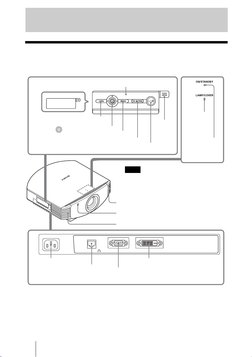
Location of Controls
Front/Right Side
You can use the buttons on the control panel with the same names as those on the remote
control to operate the projector.
Press the button and
open the cover.
M/m/</, (arrow)/
(enter) button (1 page 35)
LENS button
MENU button (1 page 35)
PIC MUTING button (1 page 26)
?/1 (ON/STANDBY) switch (1 page 20)
~AC IN
~AC IN socket
NETWORK connector (1 pages 34, 53)
Connects to a computer, etc. for remote
control.
NETWORK
Control panel
LAMP/
Open
button
Note
While the ON/STANDBY indicator lights in orange,
the power saving mode is on. (1 page 47)
Ventilation holes (exhaust) (1 page 13)
Remote control detector (1 page 19)
Ventilation holes (exhaust) (1 page 13)
REMOTE DVI-D
DVI-D connector (1 page 18)
REMOTE connector (1 page 34)
Connects to a computer, etc. for remote control.
COVER
indicator
(1 page 58)
ON/STANDBY
indicator
(1 page 19)
CAUTION
For safety, do not connect the connector for peripheral device wiring that might have excessive
voltage to the NETWORK connector.
Follow the instructions for the NETWORK connector.
CAUTION
When you connect the NETWORK cable of the unit to peripheral device, use a shielded-type cable
to prevent malfunction due to radiation noise.
GB
8
Page 9
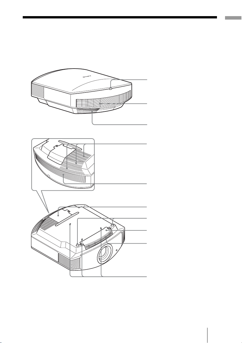
Rear/Bottom
Location of Controls
Remote control detector
(1 page 19)
Ventilation holes (intake)
(1 page 13)
Ventilation holes (intake)
(1 page 13)
Ventilation holes (intake)
(1 page 13)
Ventilation holes (intake)
(1 page 13)
Lamp cover (1 page 62)
Adjusters (1 page 23)
Filter holder (1 page 63)
Ventilation holes (intake)
(1 page 13)
Projector suspension
support attaching hole
GB
9
Page 10

Remote Control
Infrared transmitter
LIGHT button
Illuminates the buttons on
the remote control.
INPUT button
Does not function with this
unit.
COLOR SPACE button
(1 page 31)
GAMMA CORRECTION
button (1 page 31)
M/m/</, (arrow)/
buttons
(1 page 35)
MENU button
(1 page 35)
WIDE MODE button
(1 page 28)
?/1 (ON/STANDBY)
switch (1 page 20)
COLOR TEMP button
(1 page 31)
BLACK LEVEL button
(1 page 31)
LENS button
(1 page 20)
ADVANCED IRIS button
(1 page 31)
RESET button
(1 page 35)
RCP (Real Color
Processing) button
(1 page 33)
ADJ PIC button
(1 page 32)
buttons (1 page 30)
SHARPNESS +/– button
GB
10
PICTURE MODE
(1 page 41)
CONTRAST +/– button
(1 page 40)
BRIGHTNESS +/– button
(1 page 41)
Page 11

Connections and Preparations
This section describes how to install the projector and screen, how to connect the
equipment from which you project the picture.
Unpacking
Check the carton to make sure it contains the following items:
• Remote control (1) and
Size AA (R6) manganese batteries (2)
• AC power cord (1)
• ImageDirector3 CD-ROM (1)
• Operating Instructions (this manual)
Installing batteries
Two size AA (R6) batteries are supplied for the remote control. To avoid risk of explosion,
use size AA (R6) manganese or alkaline batteries.
Inserting the batteries into the remote control
Insert the batteries E side first as shown in the illustration.
Push and slide
to open.
Inserting them forcibly or with the polarities reversed may
cause a short circuit and may generate heat.
Connections and Preparations
Caution about handling the remote control
• Handle the remote control with care. Do not drop or step on it, or spill liquid of any kind
onto it.
• Do not place the remote control in a location near a heat source, a place subject to direct
sunlight, or a damp room.
CAUTION
Danger of explosion if battery is incorrectly replaced. Replace only with the same or
equivalent type recommended by the manufacturer.
When you dispose of the battery, you must obey the law in the relative area or country.
11
GB
Page 12

Step 1: Installing the Projector
The projector displays pictures output from
a computer or other device.
The lens shift allows you to have broader
options for placing the projector and
viewing pictures easily.
Before Setting Up the
Projector
Unsuitable installation
Do not place the projector in the following
situations, which may cause malfunction
or damage to the projector.
Poorly ventilated location
Leave space of more than 30 cm (11 7/8 inches)
around the unit.
Hot and humid
Installing the projector in such a location
may cause a malfunction of the unit due to
moisture condensation or rise in
temperature.
Near a heat or smoke sensor
Malfunction of the sensor may occur.
Very dusty and extremely smoky
locations
Install in a location away from walls
To maintain the performance and
reliability of the projector, allow at
least 30 cm (11
7
/8 inches) between
the projector and walls.
Locations subject to direct cool or
warm air from an air-conditioner
GB
12
30 cm
(11 7/8inches)
30 cm
(11
7
/8inches)
(11
30 cm
(11 7/8inches)
30 cm
7
/8inches)
Page 13
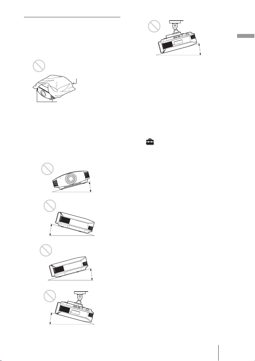
Improper use
Do not do any of the following while using
the projector.
Blocking the ventilation holes (intake
or exhaust)
Connections and Preparations
15° or more
Ventilation holes
(intake)
Ventilation holes
(exhaust)
Tip
For details on the location of the ventilation
holes (intake or exhaust), see “Location of
Controls” on page 9.
Tilting front/rear and left/right
15° or more
15° or more
Avoid using the projector tilted at an angle
of more than 15 degrees.
Do not install the projector anywhere other
than on a level surface or on the ceiling.
Installing the projector in such a location
may result in uneven color uniformity or
reduce the reliability of the effects of the
lamp.
When installing the unit at high
altitudes
When using the projector at an altitude of
1,500 m or higher, set “Cooling Setting” in the
Setup menu to “High.” (1 page 46)
Failing to set this mode when using the
projector at high altitudes could have adverse
effects, such as reducing the reliability of
certain components.
15° or more
15° or more
13
GB
Page 14

Positioning the Projector and a Screen
The installation distance between the projector and a screen varies depending on the size
of the screen or whether or not you use the lens shift features.
1 Determine the installation position of the projector and screen.
You can obtain a good quality picture if you position the projector so that the center
of the lens is within the area indicated in gray in the illustration.
Use the values L, x and y in the table on page 15 or 16 as a guide.
Screen
*
**
* Installation position not using lens shift (x = 0, y = 0)
** Example of installation position using lens shift (x, y)
L: Distance between the screen and the front end of the projector’s lens.
x: Horizontal distance between the center of the screen and the center of the
projector’s lens.
y: Vertical distance between the center of the screen and the center of the projector’s
lens.
For details on the lens shift feature, see “Step 3: Adjusting the Picture Position.”
(1 page 19)
GB
14
Page 15
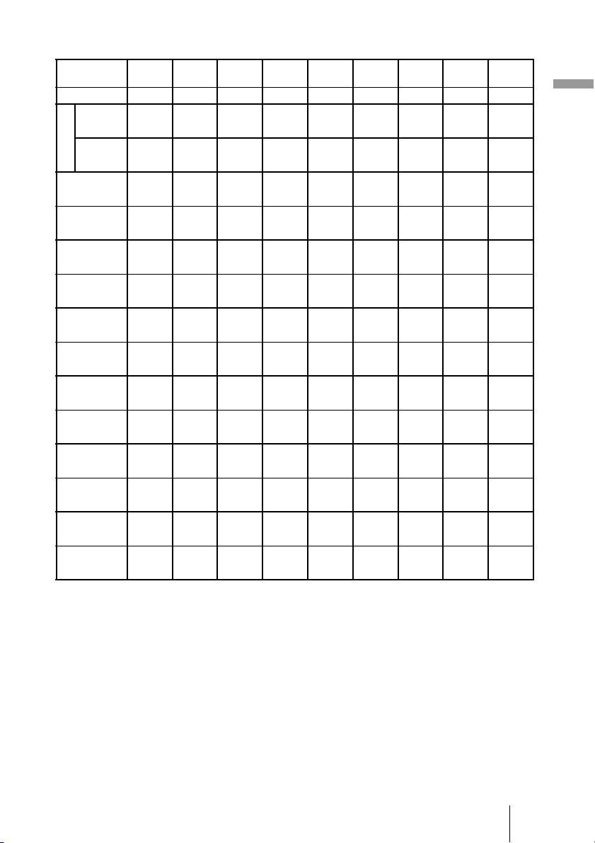
When using the 16:9 aspect ratio screen size
Screen Size
SS (inches)
(mm) 1016 1524 2032 2540 3048 3810 5080 6350 7620
minimum 1201 1825 2448 3072 3695 4631 6189 7748 9307
L
maximum 1840 2782 3723 4664 5605 7017 9371 11724 14077
x 000000000
y 324 486 648 809 971 1214 1619 2024 2428
x 44 66 89 111 133 166 221 277 332
y 259 389 518 648 777 971 1295 1619 1943
x 89 133 177 221 266 332 443 553 664
y 194 291 389 486 583 728 971 1214 1457
x 133 199 266 332 398 498 664 830 996
y 130 194 259 324 389 486 648 809 971
x 177 266 354 443 531 664 886 1107 1328
y 65 97 130 162 194 243 324 405 486
x 221 332 443 553 664 830 1107 1384 1660
y 000000000
To calculate the installation positions
L (minimum) = 31.1781 (1
L (maximum) = 47.0644 (1
y = –1.463 × x (mm or inch) + 8.0942 (
40 60 80 100 120 150 200 250 300
(47 3/8) (71 7/8) (96 1/2) (121) (145 1/2) (182 3/8) (243 3/4) (305 1/8) (366 1/2)
(72 1/2) (109 5/8) (146 5/8) (183 5/8) (220 3/4) (276 3/8) (369) (461 5/8) (554 1/4)
(0) (0) (0) (0) (0) (0) (0) (0) (0)
7
(12
/8) (19 1/4) (25 5/8)(31 7/8) (38 1/4) (47 7/8) (63 3/4)(79 3/4) (95 5/8)
3
(1
/4) (2 5/8)(3 5/8) (4 3/8) (5 1/4) (6 5/8)(8 3/4) (11) (13 1/8)
1
(10
/4) (15 3/8) (20 1/2)(25 5/8) (30 5/8) (38 1/4) (51) (63 3/4) (76 1/2)
5
(3
/8) (5 1/4) (7) (8 3/4) (10 1/2) (13 1/8) (17 1/2)(21 7/8) (26 1/4)
3
(7
/4) (11 1/2) (15 3/8)(19 1/4)(23)(28 3/4) (38 1/4)(47 7/8) (57 3/8)
1
(5
/4) (7 7/8) (10 1/2)(13 1/8) (15 3/4) (19 5/8) (26 1/4)(32 3/4) (39 1/4)
1
(5
/8) (7 3/4) (10 1/4)(12 7/8) (15 3/8) (19 1/4) (25 5/8)(31 7/8) (38 1/4)
(7) (10
5
(2
/8) (3 7/8)(5 1/8) (6 1/2) (7 3/4) (9 5/8) (12 7/8) (16) (19 1/4)
3
(8
/4) (13 1/8) (17 1/2)(21 7/8) (26 1/4) (32 3/4) (43 5/8)(54 1/2) (65 3/8)
1
/2) (14) (17 1/2)(21)(26 1/4) (35) (43 5/8) (52 3/8)
(0) (0) (0) (0) (0) (0) (0) (0) (0)
Unit: mm (inches)
7
/32) × SS – 46.1543 (1 13/16)
27
/32) × SS – 42.3308 (1 21/32)
5
/16) × SS
Connections and Preparations
15
GB
Page 16
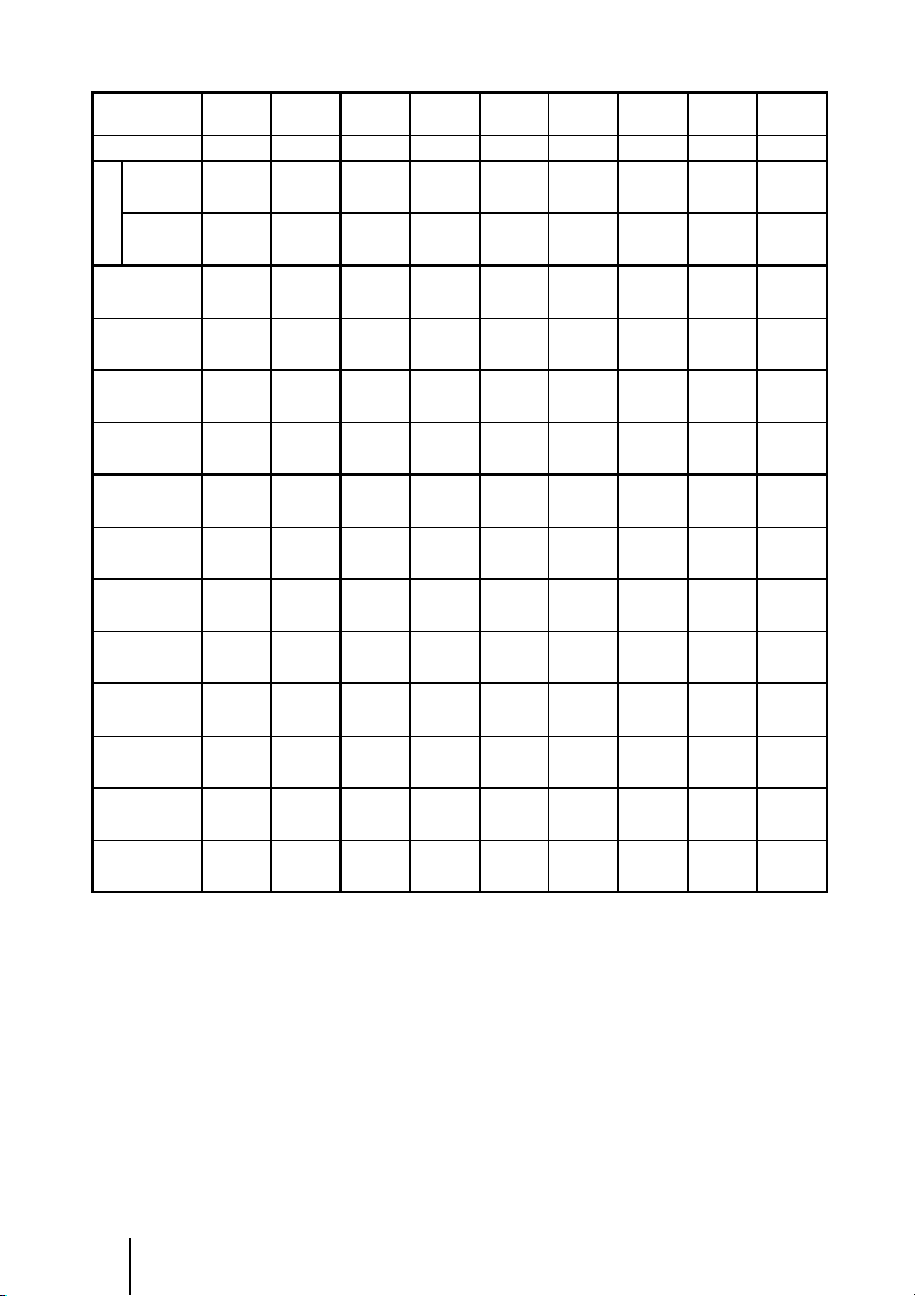
When using the 4:3 aspect ratio screen size
Screen Size
SS (inches)
(mm) 1016 1524 2032 2540 3048 3810 5080 6350 7620
minimum 1480 2243 3006 3770 4533 5677 7585 9493 11401
L
maximum 2262 3414 4566 5718 6870 8598 11478 14357 17237
x 000000000
y 396 594 792 991 1189 1486 1981 2477 2972
x 54 81 108 135 163 203 271 339 406
y 317 475 634 792 951 1189 1585 1981 2377
x 108 163 217 271 325 406 542 677 813
y 238 357 475 594 713 892 1189 1486 1783
x 163 244 325 406 488 610 813 1016 1219
y 158 238 317 396 475 594 792 991 1189
x 217 325 433 542 650 813 1084 1355 1626
y 79 119 158 198 238 297 396 495 594
x 271 406 542 677 813 1016 1355 1693 2032
y 000000000
To calculate the installation positions
L (minimum) = 38.1569 (1
L (maximum) = 57.5992 (2
y = –1.463 × x (mm or inch) + 9.9060 (
40 60 80 100 120 150 200 250 300
(58 3/8) (88 3/8) (118 3/8) (148 1/2) (178 1/2) (223 5/8) (298 5/8) (373 3/4) (448 7/8)
(89 1/8) (134 1/2) (179 7/8) (225 1/8) (270 1/2) (338 5/8) (452) (565 1/4) (678 5/8)
(0) (0) (0) (0) (0) (0) (0) (0) (0)
5
(15
/8) (23 1/2)(31 1/4) (39 1/8) (46 7/8) (58 5/8) (78) (97 5/8)
1
(2
/4) (3 1/4) (4 3/8) (5 3/8)(6 1/2) (8) (10 3/4) (13 3/8) (16)
1
(12
/2) (18 3/4) (25) (31 1/4) (37 1/2) (46 7/8)(62 1/2) (78) (93 5/8)
3
(4
/8) (6 1/2) (8 5/8) (10 3/4) (12 7/8) (16) (21 3/8) (26 3/4) (32 1/8)
3
(9
/8) (14 1/8)(18 3/4) (23 1/2) (28 1/8) (35 1/8)(46 7/8) (58 5/8) (70 1/4)
1
(6
/2) (9 5/8)(12 7/8) (16) (19 1/4) (24 1/8)(32 1/8) (40) (48)
1
(6
/4) (9 3/8)(12 1/2) (15 5/8) (18 3/4) (23 1/2)(31 1/4) (39 1/8) (46 7/8)
5
(8
/8) (12 7/8)(17 1/8) (21 3/8) (25 5/8) (32 1/8)(42 3/4) (53 3/8) (64 1/8)
1
(3
/8) (4 3/4) (6 1/4) (7 7/8)(9 3/8) (11 3/4)(15 5/8) (19 1/2) (23 1/2)
3
(10
/4) (16) (21 3/8) (26 3/4) (32 1/8) (40) (53 3/8) (66 3/4) (80)
(0) (0) (0) (0) (0) (0) (0) (0) (0)
Unit: mm (inches)
1
/2) × SS – 46.1543 (1 13/16)
9
/32) × SS – 42.3308 (1 21/32)
3
/8) × SS
(117 1/8)
GB
16
Page 17

2 Position the projector so that the lens is parallel to the screen.
Top view
Screen
3 Project an image on the screen and adjust the picture so that it fits the
screen. (1 page 19)
To project an image, connect a computer or other equipment to the projector. (1 page
18)
Note
When using a screen with an uneven surface, stripes pattern may rarely appear on the screen
depending on the distance between the screen and the projector or the zooming magnifications. This
is not a malfunction of the projector.
Connections and Preparations
17
GB
Page 18
Step 2: Connecting the Projector
When making a connection, be sure to do the following:
• Turn off the projector and a computer before making a connection.
• Use the proper connecting cable.
• Insert the cable plugs properly; poor connection at the plugs may cause a malfunction or
poor picture quality. When pulling out a cable, be sure to pull it out from the plug, not
the cable itself.
• Refer to the operating instructions of the connected equipment.
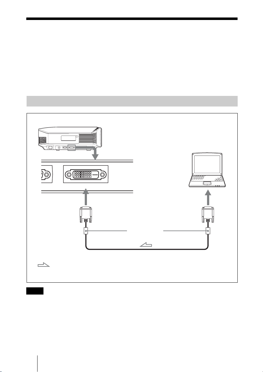
Connecting to a Computer
Right side of the projector
Computer
E DVI- D
to monitor output
Ferrite cores
DVI-DVI cable (not supplied)*
: Video signal flow
Note
If you set your computer, such as a notebook type, to output the signal to both computer’s display
and this equipment, the picture of the equipment may not appear properly. Set your computer to
output the signal to only the external equipment.
For details, refer to the computer’s operating instructions supplied with your computer. For settings
of the computer, consult with the manufacturer of the computer.
GB
18
* We recommend use of a DVI-DVI cable with ferrite
cores.
Page 19
Step 3: Adjusting the Picture Position
Project an image on the screen and then adjust the picture position.
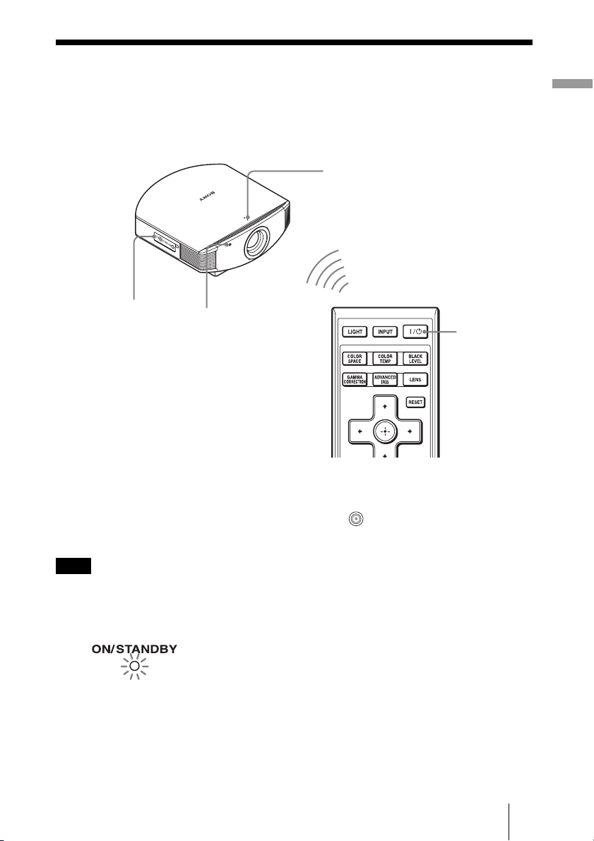
ON/STANDBY indicator
1
4, 5, 6
Lens button
Tip
?/1 (ON/STANDBY), LENS, MENU, and M/m/</,/ (joystick) buttons on the side panel
The
of the projector function the same as those on the remote control.
Remote control
detector
2
Connections and Preparations
?/1 (On/
standby)
switch
Note
Depending on the installation location of the projector, you may not control it with the remote
control. In this case, point the remote control to the screen instead of the projector.
1 After connecting the AC cord to
the projector, plug the AC cord
Lights in red.
into a wall outlet.
The ON/STANDBY indicator lights
in red and the projector goes into
standby mode.
19
GB
Page 20
Flashes in green fo
r
a while (tens of
seconds) and then
lights in green.
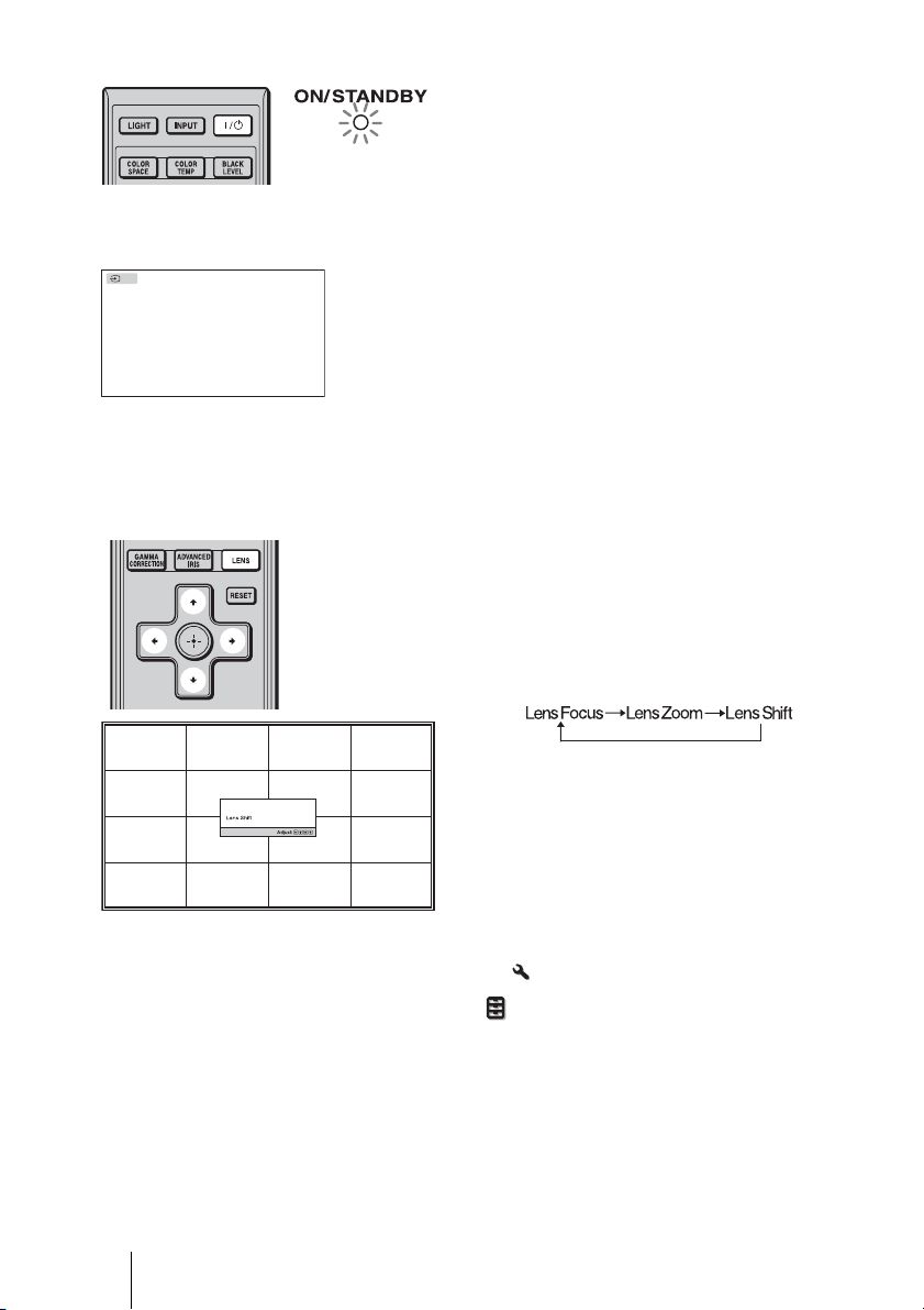
2 Press the ?/1 (ON/STANDBY)
switch to turn on the projector.
The ON/STANDBY indicator flashes
in green, and then lights in green.
When the ON/STANDBY indicator
flashes, “Starting...” appears on the
screen.
DVI
3 Turn on the equipment
connected to the projector.
Refer to the operating instructions of
the connected equipment.
The DVI indication is displayed, and
the picture is projected on the screen.
Tip
You can select the desired language for the menu screen. For details, refer to “Step 4: Selecting the
Menu Language.” (1 page 24)
4 Adjust the picture position.
Press the LENS button repeatedly until
the Lens Shift adjustment window (test
pattern) appears. Then adjust the
proper position by pressing the M/m/
</, buttons. Each time you press
the LENS button, the LENS adjustment
window appears in order.
Tip
When “Lens Control” is set to “Off” on the Installation
position. (1 page 49)
When “Test Pattern” is set to “Off” on the Function menu, the test pattern is not displayed.
(1 page 48)
menu, you cannot adjust the picture
To adjust the horizontal position
Press </,.
The picture projected on the screen moves right or left by a maximum of 25% of the screen
width from the center of the lens.
GB
20
Page 21

25% 1 screen width 25%
Top view
: Picture position when moving the picture to the left
at maximum
: Picture position when moving the picture to the
right at maximum
To adjust the vertical position
Press M/m.
The picture projected on the screen moves up or down by a maximum of 65% of the screen
height from the center of the lens.
Side view
65%
Connections and Preparations
1
screen
height
65%
Note
: Picture position when moving the picture upward at
maximum
: Picture position when moving the picture downward at
maximum
The range to move the picture projected on the screen can be adjusted only within the octagon area
illustrated below. In this connection, see “Positioning the Projector and a Screen” (1 page 14) as
well.
21
GB
Page 22

Range of movement of
the projected picture
Projected Picture
H: Width of the projected picture
V: Height of the projected picture
5 Adjust the picture size.
Press the LENS button repeatedly
until the Lens Zoom adjustment
window (test pattern) appears. Then
adjust the size of the picture by
pressing the M/m/</, buttons.
To make the picture larger, press
To make the picture smaller, press
M/,.
m/<.
Tip
When “Lens Control” is set to “Off” on the Installation
and the focus. (1 page 49)
When “Test Pattern” is set to “Off” on the Function menu, the test pattern is not displayed.
(1 page 48)
GB
22
menu, you cannot adjust the picture size
Page 23
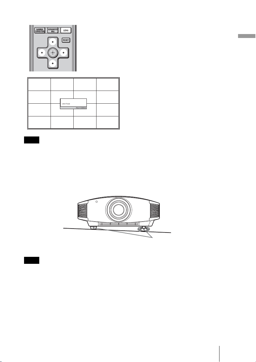
6 Adjust the focus.
Press the LENS button repeatedly
until the Lens Focus adjustment
window (test pattern) appears. Then
adjust the focus of the picture by
pressing the M/m/</, buttons.
Note
Be sure to adjust the picture size and the focus by using buttons on the remote control or the control
panel of the projector. Never make adjustments by directly turning the lens with your hands, which
may cause damage or malfunction to the projector.
To adjust the tilt of the installation surface
If the projector is installed on an uneven surface, use the adjusters to keep the projector
level.
Connections and Preparations
Adjusters
Note
Be careful not to catch your finger when turning the adjusters.
Turn to adjust.
23
GB
Page 24
Step 4: Selecting the Menu Language
You can select one of 16 languages for displaying the menu and other on-screen displays.
The factory default setting is English. To change the current menu language, set the
desired language with the menu screen.
2,3,4
M/m/</,
(arrow)/ (enter)
buttons
1
MENU button
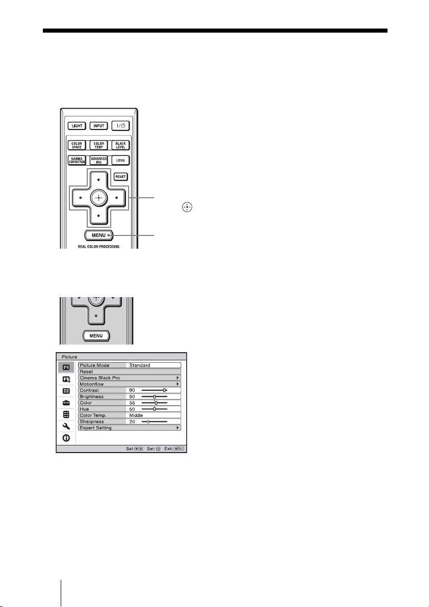
1 Press MENU.
The menu appears.
GB
24
Page 25
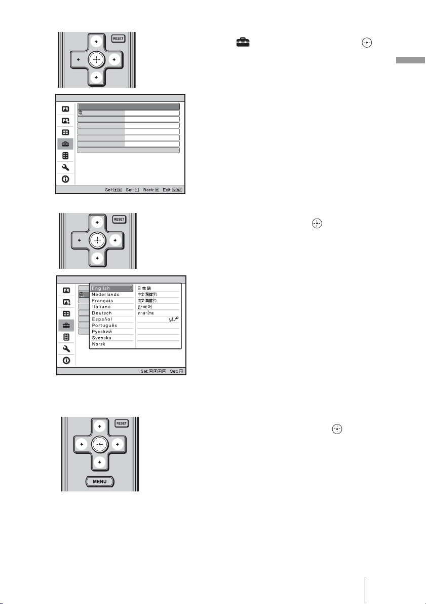
2 Press M/m to select the Setup
menu, and press , or .
The setting items of the selected menu
appears.
Connections and Preparations
Setup
Setup
Status
Language
Menu Position
Cooling Setting
Cooling Setting 2
Standby Mode
Power Saving
Lamp Setting
Status
Language
Menu Position
Cooling Setting
Cooling Setting 2
Standby Mode
Power Saving
Lamp Setting
On
English
Bottom Left
Standard
Off
Standard 2
On
On
English
Bottom Left
Standard
Off
Standard2
On
3 Press M/m to select “Language,”
and press , or .
4 Press M/m/</, to select a
language, and press .
The menu changes to the selected
language.
To clear the menu
Press MENU.
25
GB
Page 26
Projecting
Sid
This section describes how to operate the projector to view the picture from the equipment
connected to the projector. It also describes how to adjust the quality of the picture to suit
your taste.
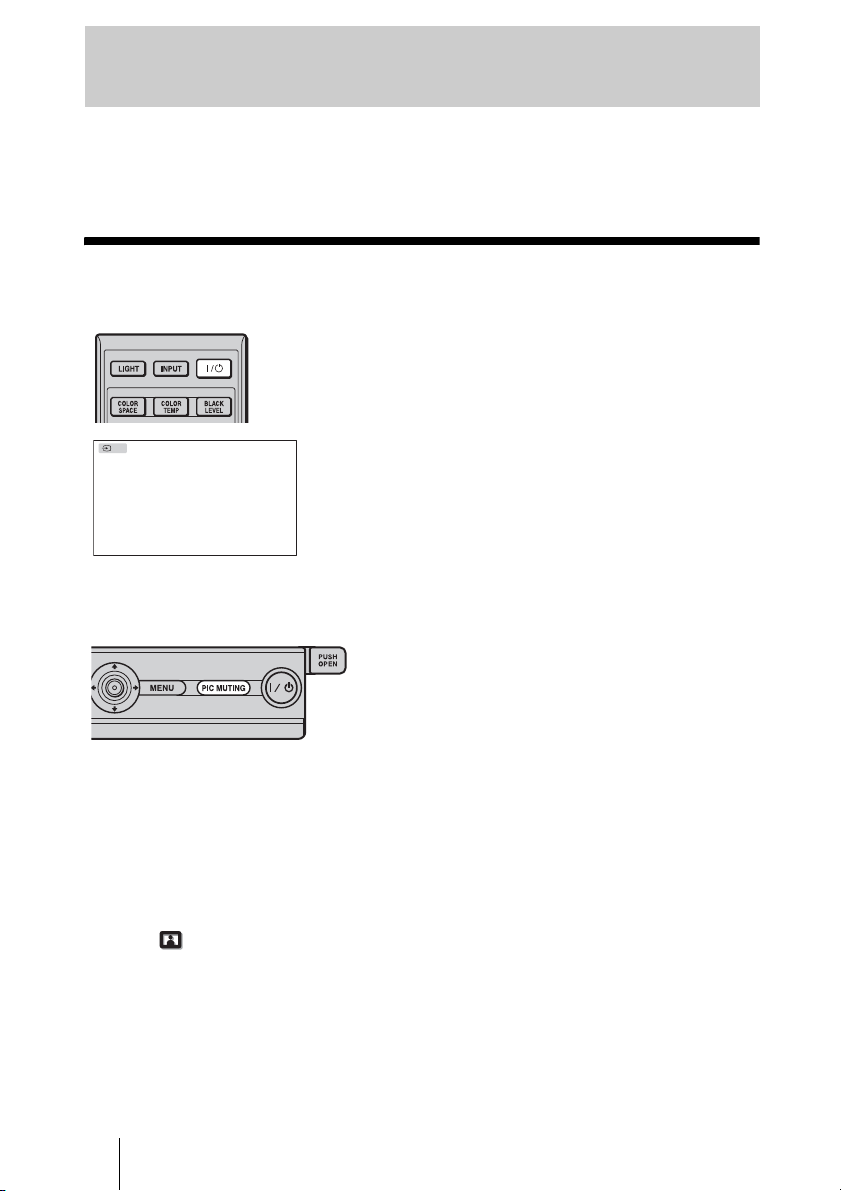
Projecting the Picture on the Screen
Power on both the projector and
the equipment connected to the
projector.
The DVI indication is displayed, and the
picture is projected on the screen.
DVI
e panel of the
projector
To cut off the picture
temporarily
Press the PIC MUTING button on the side
panel of the projector. To restore the
picture, press the PIC MUTING button
again.
Notes on input of a DVI-D signal
The projector adjusts the RGB dynamic range of the equipment connected with the DVI
cable to a Full (0-255) signal.
When a Limited (16-235) signal is input, the following symptom may occur.
• When a video signal is input, the color gradation of the dark area or bright area may
become unclear.
Full (0-255).
Picture menu of the projector. (1 pages 40 and 41)
GB
26
In this case, switch the RGB dynamic range of the connected equipment to
If this adjustment is unavailable, adjust “Brightness” or “Contrast” in the
Page 27

Turning Off the Power
1 Press the ?/1 (ON/STANDBY) switch.
A message “POWER OFF?” appears on the screen.
2 Press the ?/1 (ON/STANDBY) switch again before the message
disappears.
The ON/STANDBY indicator flashes in green and the fan continues to run to reduce the
internal heat. First, the ON/STANDBY indicator flashes quickly, during which you will
not be able to light up the ON/STANDBY indicator with the
?/1 (ON/STANDBY) switch.
3 Confirm that the fan stops running and the ON/STANDBY indicator lights
in red.
You can turn off the projector by holding the
second, instead of performing the above steps.
?/1 (ON/STANDBY) switch for about 1
Projecting
27
GB
Page 28
Selecting the Wide Screen Mode
You can enjoy various wide screen modes according to the video signal received.
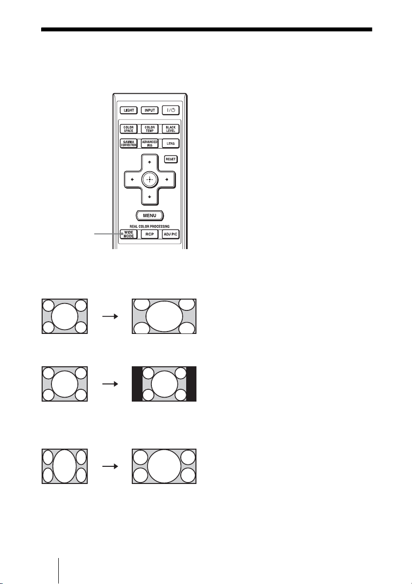
Press WIDE MODE.
Each time you press the button, you can
select the “Wide Mode” setting.
You can also select it using the menu.
(1 page 44)
WIDE MODE
button
Squeezed
GB
28
Original
image
When the Wide
Mode is operated
Wide Zoom
A 4:3 aspect ratio picture is enlarged
naturally to fill the screen. The upper and
lower portions of the screen are slightly
cut off.
Normal
A 4:3 aspect ratio picture is displayed in
the center of the screen and enlarged to fill
the screen vertically.
Full
A picture squeezed to 4:3 aspect ratio is
displayed in its original aspect ratio.
When a 4:3 aspect ratio picture is
displayed, the picture is enlarged
horizontally to fill the 16:9 screen.
Tip
Squeezed: An original 16:9 aspect ratio picture
is recorded horizontally compressed to a 4:3
picture.
Page 29
Letterbox picture with side panels
Letterbox picture
When using an
Anamorphic lens
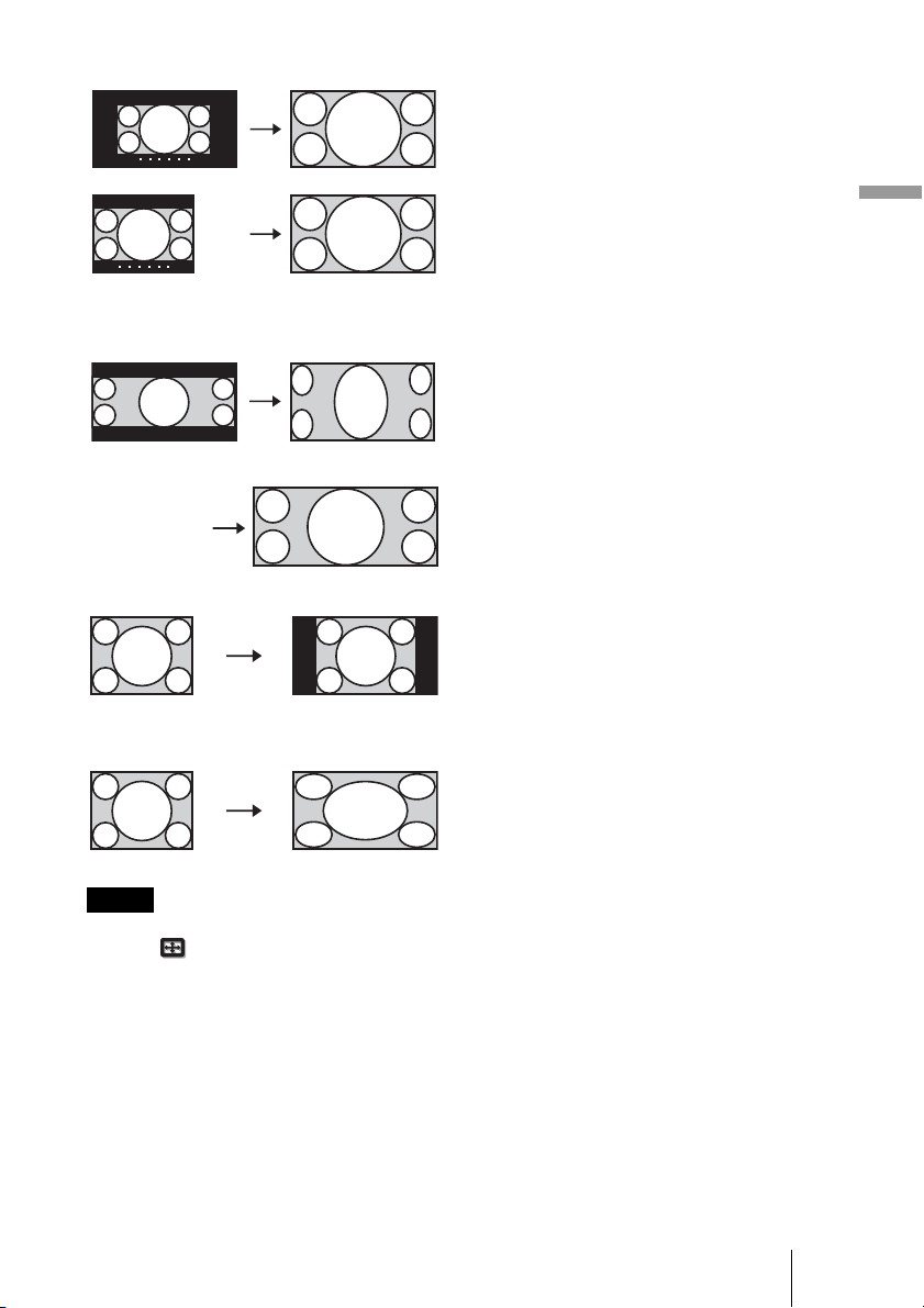
Zoom
A 16:9 aspect ratio picture is enlarged
vertically and horizontally in the same
ratio to fill the screen. Use this mode to
view a letterbox picture or a letterbox
picture with side panels.
If the subtitle of a movie, etc. is hidden
and cannot be seen, adjust the screen with
“Vertical Size” and “V Center” to display
the subtitle. (1 page 45)
Anamorphic Zoom
A 2.35:1 aspect ratio picture is converted
to a normal 16:9 picture on the screen.
This mode is best suited when using a
commercially available Anamorphic lens
which converts a normal 16:9 aspect ratio
picture to a 2.35:1 picture.
Full 1 (When a computer
signal is input)
Displays a picture on the whole of the
screen without changing the aspect ratio
of the original picture.
Projecting
Full 2 (When a computer
signal is input)
Displays a picture on the whole of the
screen.
Notes
• You can adjust the vertical position of the picture with “V Center” and “Vertical Size” in the
Screen menu only when “Zoom” is selected. (1 page 45)
• Depending on the type of Anamorphic lens, part of the screen may be cut off when you zoom in
on the picture. Check the specifications of the Anamorphic lens you use.
Notes on selecting the wide screen mode
The projector is featured with the WIDE MODE. When changing the settings of WIDE
MODE, use caution as described below.
• Select the wide screen mode taking into account that changing the aspect ratio of the
original picture will provide a different look from that of the original image.
• Note that if the projector is used for profit or for public viewing, modifying the original
picture by switching to the Wide Mode may constitute an infringement of the rights of
authors or producers, which are legally protected.
29
GB
Page 30

Selecting the Picture Viewing Mode
You can select the picture viewing mode that best suits the type of program or room
conditions.
Press one of the
PICTURE MODE buttons
(DYNAMIC, STANDARD,
CINEMA and USER 1, USER 2
and USER 3).
DYNAMIC
Vivid picture quality that enhances the
sharpness and contrast of the picture.
STANDARD
Standard picture quality that emphasizes
on naturalness.
CINEMA
Picture quality suited for watching
PICTURE MODE
buttons
DYNAMIC
STANDARD
CINEMA
USER 1,
USER 2
and USER 3
movies.
USER 1, USER 2 and USER 3
You can adjust the quality of the picture to
suit your taste and store the settings into
the selected memory of the projector.
Press one of the USER 1, USER 2 and
USER 3 buttons, then adjust the picture
by using the buttons on the remote control
or the menus (1 pages 31, 39). The
settings are stored, and you can view the
picture with the adjusted picture quality
by pressing the button.
GB
30
Page 31

Adjusting the Picture Quality
You can easily adjust the picture quality that suits your taste by selecting the adjustment
items with the remote control. The adjusted data can be stored in each picture mode.
Selecting to Directly Adjust the Desired Menu Item
The following menu items can be
adjusted by using the buttons on
COLOR SPACE
button
COLOR TEMP
button
BLACK LEVEL
button
ADVANCED IRIS
button
GAMMA
CORRECTION
button
the remote control.
“Color Space”
“Color Temp.”
“Black Level Adj.”
“Advanced Iris”
“Gamma Correction”
Press the button of the desired menu item
repeatedly to adjust the picture quality to suit
your taste. For details on each menu item,
see the Picture
menu. (1 page 39)
Projecting
31
GB
Page 32

Selecting Desired Adjust Menu Items in Sequence
1 Press ADJ PIC.
Each time you press the button, the
following adjustment windows are
displayed in sequence.
“Advanced Iris”, “Lamp Control”,
“Film Projection”, “Motion
Enhancer”, “Contrast”, “Brightness”,
“Color”, “Hue”, “Color Temp.”,
“Sharpness”, “NR”, “MPEG NR”,
2
M/m/</,
(arrow) /
(enter) buttons
“Film Mode”, “Black Level Adj.”,
“Gamma Correction”, “Color Space”
For details on each adjustment, see the
Picture menu. (1 page 39)
1
ADJ PIC
button
Example: To adjust the contrast
Note
Some adjustment windows cannot be
displayed, depending on the type of input
signal. For details, see “Input Signals and
Adjustable/Setting Items.” (1 page 69)
2 Make the setting or adjustment
on an item with M/m/</,.
When changing the adjustment
level
To increase the value, press M/,.
To decrease the value, press m/<.
When changing the setting
Press M/m to change the setting.
GB
32
Page 33

Adjusting the Picture Using Real Color
Processing
The Real Color Processing (RCP) feature allows you to adjust the color and hue of each
target of the projected picture you specify independently. You can thus obtain a picture
more suitable to your taste.
Tip
Freeze the scene of the video source when you are adjusting the picture using Real Color Processing.
1 Press RCP on the remote
control.
2 Press M/m to select “User 1,”
“User 2” or “User 3,” then press
,.
2, 3, 4, 5
M/m/</,
(arrow) /
(enter) buttons
1
RCP (Real Color
Processing)
button
The RCP (Real Color Processing)
window appears.
3 Select the target color you want
to adjust.
Repeat steps 1 and 2 described
below to specify the target color.
Projecting
Reference palette
1 Press
M/m to select
“Color Select,” then press
to select the color you want to
adjust among “Red,” “Yellow,”
“Green,” “Cyan,” “Blue” and
“Magenta.”
Only the portions that correspond
to the specified color will be
colored and the other portions will
be displayed in black and white.
The reference palette in the RCP
window also shows the adjustable
colors. Select the desired setting to
adjust the color on the projected
image using the reference palette
as a guide.
</,
33
GB
Page 34

2 Press M/m to select “Position” or
“Range,” and specify it more
delicate color position and color
range you want to adjust using
</,.
4 Adjust the color of the specified
portions.
Press
M/m to select “RCP Color” or
“RCP Hue,” then adjust the color or
hue of the portions selected in step 3 to
suit your taste using
watching the projected picture. The
picture is returned to normal color
during adjustment.
</, while
5 After the adjustment is
complete, press .
The RCP window disappears and the
picture of step 2 appears. Then after a
few seconds, normal picture is
restored.
Tip
There are some limitations on selection of
position and range.
Using the Supplied Software to Adjust the
Picture Quality (ImageDirector3)
By using the “ImageDirector3” (supplied as a CD-ROM), you can make the desired
gamma correction from a computer connected to the projector. Connect the REMOTE or
NETWORK connector of the projector with a computer and start-up “ImageDirector3” on
the computer.
For details on how to use the “ImageDirector3”, refer to the Help within the CD-ROM.
Notes
• You need to install the “ImageDirector3” on a computer beforehand.
• When connecting the REMOTE or NETWORK connector on the projector with a computer, turn
off the powers of the computer and the projector.
GB
34
Page 35

Using the Menus
This section describes how to make various adjustments and settings using the menus.
Operation through the Menus
The projector is equipped with an on-screen menu for making various adjustments and
settings. Some of the adjustable/setting items are displayed in a pop-up menu, in a setting
menu or adjustment menu with no main menu, or in the next menu window. If you select
an item name followed by an arrow (
To change the on-screen menu language, see “Step 4: Selecting the Menu Language.”
(1 page 24)
RESET button
B), the next menu window with setting items appears.
Using the Menus
2, 3, 4
M/m/</, (arrow) /
(enter) buttons
1
MENU button
35
GB
Page 36

Setup
Status
Language
Menu Position
Cooling Setting
Cooling Setting 2
Standby Mode
Power Saving
Lamp Setting
On
English
Bottom Left
Standard
Off
Standard 2
On
1 Press MENU.
The menu window appears.
2 Press M/m to select a menu item,
and press , or .
The items that can be set or adjusted
with the selected menu appear. The
item presently selected is shown in
yellow.
GB
36
Page 37

Pop-up menu
Setup
Status
Language
Menu Position
Cooling Setting
Cooling Setting 2
Standby Mode
Power Saving
Lamp Setting
Setting menu
Setting items
On
English
Bottom Left
Standard
Off
Standard2
On
3 Press M/m to select an item you
want to set or adjust and press
, or .
The setting items are displayed in a
pop-up menu, in a setting menu, in an
adjustment menu or in the next menu
window.
Using the Menus
Adjustment menu
Next menu window
Setting items
Off
GB
37
Page 38

4 Make the setting or adjustment
of an item.
When changing the adjustment
level
To increase the value, press M/,.
To decrease the value, press m/<.
Press to restore the original screen.
When changing the setting
Press M/m to change the setting.
Press to restore the original screen.
You can restore the original screen
using < depending on the selected
item.
Items that cannot be adjusted
Adjustable items differ depending on the
input signal. The items that cannot be
adjusted or set do not appear in the menu.
(1 page 69)
To clear the menu
Press MENU.
To reset the picture that has
been adjusted
Select “Reset” from Picture menu.
To reset the items that have
been adjusted
Select an item in the Menu screen, and
display the pop-up menu, the setting
menu, and the adjustment menu.
Press the RESET on the remote control to
reset only the selected settings to its
factory preset value.
Note
The RESET button on the remote control is
available only when the adjustment menu or
the setting menu is selected.
When the screen display appears, select
“Yes” using < and press .
All of the following settings are reset to its
factory preset value.
The settings of “Cinema Black Pro,”
“Motionflow,” “Contrast,” “Brightness,”
“Color,” “Hue,” “Color Temp.,”
“Sharpness” and “Expert Setting” on the
Picture
GB
38
menu
Page 39

Picture Menu
The Picture menu is used for adjusting the picture.
Picture Mode
Note
Some items may not be available, depending on the type of input signal. For details, see “Input
Signals and Adjustable/Setting Items.” (1 page 69)
Using the Menus
Picture Mode You can select the picture viewing mode that best suits the type of
picture or the environment.
Dynamic: Vivid picture quality that enhances sharpness and contrast of
the picture.
Standard: Standard picture quality that emphasizes on naturalness.
Cinema: Picture quality suited for watching movies.
User 1, User 2, User 3: You can adjust the quality of the picture to suit
your taste and then store the settings. Once the settings are stored, you
can view the picture with the adjusted picture quality by pressing the
PICTURE MODE button on the remote control.
To store the settings
1 Select User 1, User 2, or User 3.
2 Adjust the items you want in the menus.
Tip
You can also store the settings if the picture quality is adjusted in
“Dynamic,” “Standard” or “Cinema.” To reset everything to the factory
settings, select “Reset” from the menu.
39
GB
Page 40

Cinema Black Pro Advanced Iris
Switches the iris function during projection.
Auto 1: Automatically switches to an optimum iris according to a
projected scene. The contrast of the scene is emphasized most.
Auto 2: An optimum iris becomes smaller than that when set to
“Auto 1.” The contrast of the scene becomes reduced.
Sensitivity: If “Auto 1” or “Auto 2” is selected, “Recommend,” “Fast” or
“Slow” can be selected according to the desired response speed with
Sensitivity Mode.
Manual: Manually adjusts the Iris.
Off: Normal contrast.
Lamp Control
Switches the lamp wattage during projection.
High: Normal wattage.
Low: Enhances the black by reducing the lamp wattage.
Tip
When you switch from “Low” to “High,” the number of fan rotation
increases, and the fan noise becomes slightly louder.
Motionflow Film Projection
Reproduces movies in its original moving picture.
Mode 1: Black Frame Insertion Mode (for motion blur reduction).
Mode 2: Dark Frame Insertion Mode (for motion blur reduction). The
picture is brighter than in “Mode 1.”
Off: Normal picture.
Note
When you select “Mode 1” or “Mode 2,” the picture will become slightly
darker than in “Off.”
Motion Enhancer
Reproduces fast-moving pictures smoothly without generating
afterimages.
High: Select this for picture quality smoother than “Low.”
Low: Select this for smooth picture quality.
Off: Select “Off” when noise, etc. appears in “High” or “Low.” Usually,
set “Motion Enhancer” to “Off.”
Note
Depending on the scene, a noise may appear on the picture.
Contrast Adjusts the white area of pictures (white level).
The higher the setting, the greater the contrast. The lower the setting, the
lower the contrast.
You can make adjustments by pressing the CONTRAST+/– on the
remote control.
GB
40
Page 41

Brightness Adjusts the brightness of the picture.
The higher the setting, the brighter the picture. The lower the setting, the
darker the picture.
You can make adjustments by pressing the BRIGHTNESS+/– on the
remote control.
Color Adjusts the intensity of the color density.
The higher the setting, the greater the intensity. The lower the setting, the
lower the intensity.
Hue Adjusts the color tone.
The higher the setting, the more greenish the picture becomes. The lower
the setting, the more reddish the picture becomes.
Color Temp. Adjusts the color temperature.
High: Gives white colors a blue tint.
Middle: Gives a neutral tint between “High” and “Low.”
Low: Gives white colors a red tint.
Custom 1, Custom 2, Custom 3, Custom 4: Enables you to adjust, set,
and store your favorite color temperature.
Sharpness Sharpens the outline of the picture, or reduces the noise.
The higher the setting, the sharper the picture. The lower the setting, the
softer the picture, thus reducing the noise.
You can make adjustments by pressing the SHARPNESS+/– on the
remote control.
Expert Setting NR (Noise Reduction)
Reduces the roughness or noise of the picture.
Usually, select “Off.”
If the picture is rough or noisy, select a setting from among “Low,”
“Middle” or “High” according to the input signal source.
MPEG NR (MPEG Noise Reduction)
Reduces block noise and mosquito noise.
Block NR: Reduces digital noise that appears in mosaic-like pattern.
Mosquito NR: Reduces digital noise that appears near the outline of the
picture.
Film Mode
According to the film source you have selected, make a setting for
playback.
Auto 1: Suited for reproducing a picture movement close to the original
picture movement of the film source. Normally, set this to “Auto 1.”
Auto 2: Reproduces a 2-3 or 2-2 Pull-Down format video signal, such as
film sources, in a smooth picture movement. When a video signal
other than 2-3 or 2-2 Pull-Down format is input, the picture is played
back in progressive format.
Off: Plays back the picture in progressive format without detecting
video signals automatically.
Black Level Adj. (Adjust)
Produces a bolder, dynamic picture.
Set according to the input signal source.
High: Gives higher emphasis to the black color.
Low: Gives lower emphasis to the black color.
Off: Cancels this feature.
Using the Menus
41
GB
Page 42

Expert Setting Gamma Correction
Adjusts the response characteristics of the tone of the picture.
Select a favorite tone from 6 options.
Gamma 1: Makes the scene much brighter overall.
Gamma 2: Makes the scene brighter overall.
Gamma 3: Makes the scene slightly brighter overall.
Gamma 4: Makes the scene darker overall.
Gamma 5: Gamma curve is set to a setting that makes the dark area of
the screen brighter and is suited for when using a matt projection
screen.
Gamma 6: Gamma curve is set to a setting that makes the bright area of
the screen even brighter.
Off: Gamma Correction is “Off.”
Using the specified controller, “ImageDirector3” (supplied as a CDROM) allows you to adjust, set, and store a favorite tone in a computer.
For detailed information on “ImageDirector3,” refer to the Help
provided on the supplied CD-ROM in the computer.
Color Space
You can convert the range of color reproduction.
Normal: Converts the color tones to those that match the specifications
of Hi-Vision signal.
Wide: Reproduces more natural color tones in a wider range of color
reproduction, compared to “Normal.”
GB
42
Page 43

Advanced Picture Menu
The Advanced Picture is used for adjusting the picture more.
Using the Menus
RCP (Real Color
Processing)
You can adjust the color and hue of each selected portion of the
picture independently.
User 1, User 2, User 3: You can adjust the picture using Real Color
Processing and store the settings. Once the settings are stored, you can
view the picture with the adjusted picture quality.
Off: Cancels this feature.
For details, see “Adjusting the Picture Using Real Color Processing.”
(1 page 33)
43
GB
Page 44

Screen Menu
The Screen menu is used to adjust the input signal. You can adjust the size of the picture,
and select wide screen mode, etc.
.
Note
These items may not be available, depending on the type of input signal. For details, see “Input
Signals and Adjustable/Setting Items.” (1 page 69)
Wide Mode
(Video signal)
Wide Mode
(Computer signal)
You can set the aspect ratio of the picture to be displayed for the
current input signal. (1 page 28) This item is enabled only when a
video signal (preset memory numbers 3 to 8, 10 to 14)
(1 pages 67, 68) is input.
Wide Zoom: A 4:3 aspect ratio picture is enlarged naturally to fill the
screen. The upper and lower portions of the screen are slightly cut off.
Normal: A 4:3 aspect ratio picture is displayed in the center of the
screen and enlarged to fill the screen vertically.
Full: A picture squeezed to 4:3 aspect ratio is displayed in its original
aspect ratio. When a 4:3 aspect ratio picture is displayed, the picture is
enlarged horizontally to fill the 16:9 screen.
Zoom: A 16:9 aspect ratio picture is enlarged vertically and horizontally
in the same ratio to fill the screen.
Anamorphic Zoom: A 2.35:1 aspect ratio picture is converted to a
normal 16:9 picture on the screen. This mode is best suited when
using a commercially available Anamorphic lens which converts a
normal 16:9 aspect ratio picture to a 2.35:1 picture. (1 page 29)
You can switch settings by pressing WIDE MODE on the remote
control.
You can set the aspect ratio of the picture to be displayed for the
current input signal. (1 page 29) This item is enabled only when a
computer signal is input.
Full 1: Displays a picture on the whole of the screen without changing
the aspect ratio of the original picture.
Full 2: Displays a picture on the whole of the screen.
Zoom: A 16:9 aspect ratio picture is enlarged vertically and horizontally
in the same ratio to fill the screen.
You can switch settings by pressing WIDE MODE on the remote
control.
GB
44
Page 45

Over Scan Hides the outline of the picture.
On: Hides the outline of the input picture. Select this setting when noise
appears along the edge of the picture.
Off: Projects the whole of the input picture.
Tip
To display the displayable region within the four directions of the screen,
refer to “Blanking” on the Installation menu (1 page 49).
Screen Area Selects the size of the picture when a Hi-Vision picture is
overscanned.
Full: Expands the picture on the whole of the screen.
Through: Does not expands the picture on the whole of the screen.
V Center Adjust the whole picture by moving up and down on the screen.
As the selected number increases, the screen moves up, and as the
selected number decreases, the screen moves down.
Vertical Size Reduces or enlarges the picture vertically.
The screen is enlarged as the setting increases and reduced as the setting
decreases. If the subtitle of a movie, etc. cannot be seen, use this together
with “V Center.”
Adjust Signal You can adjust the input signal.
Shift: Adjusts the position of the picture.
H: As the setting for H (horizontal) increases, the picture moves
to the right, and as the setting decreases, the picture moves to
the left. Use < / , to adjust the horizontal position.
V: As the setting for V (vertical) increases, the picture moves up,
and as the setting decreases, the picture moves down. Use M /
m to adjust the vertical position.
Using the Menus
45
GB
Page 46

Setup Menu
The Setup menu is used to change the factory preset settings, etc.
Setup
Status
Language
Menu Position
Cooling Setting
Cooling Setting 2
Standby Mode
Power Saving
Lamp Setting
On
English
Bottom Left
Standard
Off
Standard 2
On
Status Sets whether or not the on-screen display is to be displayed.
Set to “Off” to turn off the on-screen displays except for certain
menus, the message displayed when you turn off the power, and
warning messages.
Set to “All Off” to turn off the on-screen displays except for certain
menus and the message displayed when you turn off the power.
(1 page 59)
Language Selects the language used in the menu and on-screen displays.
Available languages are: English, Dutch, French, Italian, German,
Spanish, Portuguese, Russian, Swedish, Norwegian, Japanese,
Chinese (Simplified Chinese), Chinese (Traditional Chinese),
Korean, Thai and Arabic.
Menu Position You can change the position to display the menu on the upper
screen.
Bottom Left: Displays the menu on the bottom left area of the
screen.
Center: Displays the menu on the center of the screen.
Cooling Setting Use this item when using the projector at high altitudes.
High: Use this setting when using the projector at an altitude of
1,500 m or higher.
Standard: Use this setting when using the projector at normal
altitudes.
Note
When this item is set to “High,” the fan noise becomes slightly
louder since the number of fan rotation increases.
Cooling Setting 2 Use this item only when the projector will be used in special
circumstances.
Normally, set this item to “Off.”
GB
46
Page 47

Standby Mode Lowers the power consumption in standby.
Standard 1: Sets power consumption to normal.
Standard 2: Sets the network function ineffective and power
consumption lower than “Standard 1.”
Low: Sets power consumption lower than “Standard 2.”
Note
When this item is set to “Low” or “Standard 2,” the network function
will not operate in standby.
Power Saving Sets the power saving mode.
When set to “On”, the projector goes into power saving mode if no
signal is input for 10 minutes. At that time, the ON/STANDBY
indicator lights in orange, then the screen becomes dark. The power
saving mode is cancelled if a signal is input or any button on the
projector or the remote control is pressed. If you do not want to set
the projector to power saving mode, select “Off.”
Lamp Setting Selects this item after you have replaced the lamp.
(1 page 63)
Using the Menus
47
GB
Page 48

Function Menu
The Function menu is used for changing the settings of the functions of the projector.
Function
Test Pattern
Background
Off
Blue
Tes t P attern Displays the test pattern.
When set to “On,” a test pattern appears on the screen to be used
when adjusting the lens with “Lens Focus,” “Lens Zoom,” and “Lens
Shift.” A test pattern does not appear when this item is set to “Off.”
Tip
While the test pattern is displayed, it is only displayed in green to
allow you to adjust the focus easily.
Background Selects the background color of the screen when no signal is input.
You can select “Black” or “Blue.”
GB
48
Page 49

Installation Menu
The Installation menu is used for changing the installation settings.
Using the Menus
Image Flip Flips the picture on the screen horizontally and/or vertically.
Lens Control Avoids any operation of the lens such as “Lens Focus,” “Lens
IR Receiver Selects the remote control detectors (IR Receiver) on the front
Blanking This feature allows you to adjust the displayable region within
HV: Flips the picture horizontally and vertically.
H: Flips the picture horizontally.
V: Flips the picture vertically.
Off: The picture does not flip.
Use this item for installation for the backside projection or ceiling
installation.
Zoom,” and “Lens Shift,” by mistake.
When set to “On,” you can adjust the projection lens using “Lens
Focus,” “Lens Zoom,” and “Lens Shift.” After you make this
adjustment, it is recommended that you set this item to “Off” to
avoid any operation of the lens.
and rear of the projector.
Front & Rear: Activates both the front and rear detectors.
Front: Activates the front detector only.
Rear: Activates the rear detector only.
the four directions of the screen.
Select each screen edge “Left / Right / Top / Bottom” on the
Blanking adjustment screen with M / m buttons. Adjust the desired
Blanking value with < / , button.
49
GB
Page 50

Panel Alignment This feature allows you to adjust the gaps in the color of
characters or the picture.
When set to “On,” “Adjust Color” and “Pattern Color” can be
assigned and adjusted.
Adjust Item: Selects how to make adjustments from below.
Shift: Shifts the whole picture and makes adjustments.
Zone: Selects the desired range and makes adjustments.
Adjust Color: Assigns the desired color to adjust the gaps in color.
Select “R” (Red) or “B” (Blue) to make adjustments based on
“G” (Green).
Pattern Color: Select “R/G” (Red and Green) or “R/G/B” (White,
all colors) when the “Adjust Color” is “R” (Red). Select “B/G”
(Blue and Green) or “R/G/B” (White, all colors) when the “Adjust
Color” is “B” (Blue).
Adjust: The shift adjustment and zone adjustment of the color
selected in “Adjust Color” can be made with < / ,, M / m
buttons.
When “Shift” is selected: Assign the settings of the horizontal
direction (H) with < / , buttons and the vertical direction (V)
with M / m buttons on the shift adjustment screen.
When “Zone” is selected: Select the position to adjust with
< / , buttons for the horizontal position (H position) and M / m
buttons for the vertical position (V position), then press .
GB
Set the amount to adjust with < / , buttons for the horizontal
direction (H direction) and with M / m buttons for the vertical
direction (V direction). You can select the position to adjust again by
pressing .
Reset: Returns to the factory settings.
Note
Depending on the adjustments made above, colors may become
uneven or the resolution may change.
50
Page 51

Network Setting You can configure the network settings such as IP address,
Subnet Mask, Default Gateway, and DNS Server when accessing
the projector from a computer or using the supplied application
“ImageDirector3.”
IP Address Setup
Select either “Auto (DHCP)” or “Manual.” When you select
“Manual,” you can set “IP Address,” “Subnet Mask,” “Default
Gateway,” “Primary DNS” and “Secondary DNS.” After completing
all the settings, select “Apply” using the m button, then press the
button.
IP Address
Sets the IP Address of the projector.
(1.0.0.0 to 223.255.255.255)
Subnet Mask
Sets the Subnet Mask of the projector.
(1.0.0.0 to 255.255.255.255)
Default Gateway
Sets the Default Gateway of the projector.
(1.0.0.0 to 223.255.255.255)
Primary DNS
Sets the DNS server to be used as a priority.
(1.0.0.0 to 223.255.255.255)
Secondary DNS
Sets the alternative DNS server.
(1.0.0.0 to 223.255.255.255)
MAC Address
Displays MAC address of the projector. You cannot change this
setting.
Using the Menus
51
GB
Page 52

Information Menu
The Information menu displays the model name, serial number, memory number of the
input signal and the cumulated hours of usage of the lamp.
Model Name
Serial No.
Lamp Timer
VPL-GH10
9999999
No. 12
1080/60p
1234 H
Model name Displays the model name (VPL-GH10).
Serial No. Displays the serial number.
Memory No. Displays the preset memory number of the input signal.
Signal type Displays the type of the input signal.
Lamp Timer Indicates how long the lamp has been turned on (total usage).
Notes
• fH (horizontal frequency) and fV (vertical frequency) may not be displayed appropriately
depending on the input signal used on the projector.
• You cannot change the displays listed above.
Model name: VPL-GH10
Serial No.
Memory No.
Signal type
About the Preset Memory No.
This projector has 19 types of preset data for input signals (the preset memory). When the
preset signal is input, the projector automatically detects the signal type and recalls the
data for the signal from the preset memory to adjust it to an optimum picture. The memory
number and signal type of that signal are displayed in the Information menu.
You can also adjust the preset data through the Screen menu.
See the chart on page 67 to find if the signal is registered to the preset memory.
Note
When the aspect ratio of input signal does not match the screen size, a part of the screen is displayed
in black.
GB
52
Page 53

Operating the Projector from a
Computer
Accessing the
Projector from a
Computer
You can check the present status of the
projector on a computer display and control
the projector from a computer.
Confirm that the projector and computer are
connected to the router/hub with the LAN
cables, then turn on the projector, computer
and router/hub.
1 Start Internet Explorer 5.0 or
later version on your computer.
2 Type “http://xxx.xxx.xxx.xxx (the
IP address of the projector)” as
the “Address,” then press the
ENTER key on a keyboard.
You can check the IP address of the
projector using the Installation menu.
(1 page 51)
Enter the IP address here.
Checking the Status
of the Projector
Click “Information.” You can check the
information and present status of the
projector on a computer display. You can
check the information and status in the
window, but you cannot change the setting.
Information
The present status of the projector is
displayed.
Note
fH (horizontal frequency) and fV (vertical
frequency) may be displayed when
unacceptable signal is input.
Menu
The present settings of the projector are
displayed.
Operating the Projector from a Computer
Tip
When “Standby Mode” in Setup menu
is set to “Standard 1”, you can access the
projector from a computer even if the
projector is in standby mode.
53
GB
Page 54

Operating the
Projector
Setting the
Information
Click “Control.” You can perform various
adjustments and settings of the projector on
a computer display.
The functions of the buttons in the windows
are the same as those on the remote control
supplied with the projector.
Settings of the projector are lit.
After you have changed the settings on the
projector, click “Refresh” at the upper righthand corner of the window to update the
status. The lighting buttons are changed.
Click “Setup.” The Password Properties
dialog box appears. The name of the “User”
account is preset without a password to
“root” at the factory. You can set the owner
information, etc. Click “Apply” at the lower
part of each window to update the projector
to the data input in each window.
Owner and projector information
Click “Owner Information.”
Owner
Enter owner information.
Projector
Enter the location of the projector.
GB
Memo
Enter a memo, if required.
Network settings
Click “Network.”
Internet Protocol (TCP/IP)
Normally, set “Obtain an IP address
automatically (DHCP).” If you select
“Specify an IP address,” set the necessary
items.
54
Page 55

Setting passwords for
“Administrator” and “User”
Click “Password.” You can set passwords
for each “Administrator” and “User.” The
name of the “Administrator” account is
preset to “root” at the factory. It cannot be
changed.
Advanced setting
Click “Advanced Menu” to display the
Advertisement button, PJ Talk button,
SNMP button and Reset button. These
settings are mainly for professional use.
Detailed information on Advertisement
button and PJ Talk button are indicated by
the PROTOCOL manual. For details on each
function of “Advanced setting”, consult with
your local dealer or qualified Sony
personnel.
To reset the setting
Click the Reset button displayed in
“Advanced setting.” The data set in “Setup”
are reset to its factory preset value.
Notes
• The data input will be recorded in the
memory of the projector.
• These data may become a personal
information, depending on the content input.
Therefore, it is recommended that you input
content that cannot specify particular
individuals.
• These data may be sent out through the
network by “Advertisement,” “PJTalk” and
“SNMP” functions.
• On disposal or transfer of the projector, it is
strongly recommended that you delete the
data recorded in the memory of the projector.
On how to delete the data, see “To reset the
setting.”
Operating the Projector from a Computer
55
GB
Page 56

Others
This section describes how to solve the problems, how to replace the lamp and air filter,
etc.
Troubleshooting
If the projector appears to be operating erratically, try to diagnose and correct the problem
using the following instructions. If the problem persists, consult with qualified Sony
personnel.
Power
Symptom Cause and Remedy
The power is not turned on. c The power may not turn on if you turn the power off with ?/1
Picture
(ON/STANDBY) switch and turn it on again in a short time.
After about 1 minute, turn the power on.
c Close the lamp cover securely, then tighten the screws securely.
(1 page 62)
c Close the filter holder securely. (1 page 63)
c Check warning indicators. (1 page 58)
Symptom Cause and Remedy
No picture. c Check that the proper connections have been made.
The bright area of the
picture may become
unclear. (When video
signal is input)
The picture is too dark. c Adjust the “Contrast” or “Brightness” of the Picture menu
The picture is not clear. c Adjust the focus. (1 page 23)
The color of characters or
the picture is not
appropriate.
Image is left on the screen.
(image retention)
GB
56
(1 page 18)
c Set the computer signal to output from an external monitor.
c Set the computer signal to output only to an external monitor.
c Switch the RGB dynamic range of the connected equipment to
Full (0-255). If this adjustment is unavailable, adjust
“Brightness” or “Contrast” in the Picture menu of the
projector. (1 pages 40, 41)
properly. (1 pages 40, 41)
c Condensation has accumulated on the lens. Leave the projector
for about 2 hours with the power on.
c Select the desired color registration in “Panel Alignment” of
Installation menu. (1 page 50)
c When high contrast non-moving images are displayed for a long
period of time, there may be some image retention on the
screen. This is only a temporary condition. Turning off the
power for a while will eliminate the retained image.
Page 57

On-screen display
Symptom Cause and Remedy
On-screen display does not
appear.
The model name does not
disappear from the screen.
Or else, the demo mode is
displayed continuously.
c Set “Status” in the Setup menu to “On.” (1 page 46)
c Check if the ON/STANDBY indicator should light in green.
c The display mode of the projector may be set at the time of
purchase. Consult with your local dealer or qualified Sony
personnel.
Remote control
Symptom Cause and Remedy
The remote control does
not work.
c Batteries could be weak. Replace them with new batteries.
(1 page 11)
c Insert the batteries with the correct polarities. (1 page 11)
c If there is a fluorescent lamp near the remote control detector, the
projector may work improperly or inadvertently.
c Set “IR Receiver” to “Front & Rear” on the Installation menu.
(1 page 49)
Others
Symptom Cause and Remedy
The fan is noisy. c Check the setting of “Cooling Setting” in the Setup menu.
The lens shift cannot be
adjusted.
(1 page 46)
c Make sure that the room temperature is not too high.
c Check the installation conditions. (1 page 12)
The number of fan rotation increases to maintain the product
reliability of the projector’s components in a room, where the
temperature is higher than normal. The fan noise becomes
slightly louder. The approximate normal temperature is 25°C.
c The lens shift cannot be adjusted over the range of movement.
Adjust the lens shift within the range of movement. (1
pages 14, 21)
Others
57
GB
Page 58

Warning Indicators
The ON/STANDBY or LAMP/COVER indicator lights up or flashes if there is any
trouble with your projector.
LAMP/COVER indicator
ON/STANDBY indicator
Symptom Cause and Remedy
LAMP/COVER flashes in
red. (A repetition rate of 2
flashes)
LAMP/COVER flashes in
red. (A repetition rate of 3
flashes)
ON/STANDBY flashes in
red. (A repetition rate of 4
flashes)
ON/STANDBY flashes in
red. (A repetition rate of 2
flashes)
c Close the lamp cover securely, then tighten the screws securely.
(1 page 62)
c Close the filter holder securely. (1 page 63)
c The lamp has reached the end of its useful lifespan. Replace the
lamp. (1 page 61)
c The lamp has reached a high temperature. Wait until the lamp
cools, and then turn on the power again.
c The fan is broken. Consult with qualified Sony personnel.
c The internal temperature is unusually high. Check to ensure that
nothing is blocking the ventilation holes or whether or not the
projector is being used at high altitudes.
ON/STANDBY flashes in
red. (A repetition rate of 6
flashes)
Note
When a warning indicator other than the above starts flashing, and the symptom persists even after
carrying out the above methods, consult with qualified Sony personnel.
GB
58
c Press the
the power is not turned on, disconnect the AC power cord, then
confirm the ON/STANDBY lamp is turned off. After about 10
seconds, reconnect the AC power cord and turn on the power
again. If the indicators still light up, the electrical system has a
problem. Consult with qualified Sony personnel.
?/1 (ON/STANDBY) switch to turn on the projector. If
Page 59

Message Lists
Note
If “Status” is set to “All Off” in the Setup menu, the warning/caution messages are not
displayed except for the message marked with an asterisk (*). (1 page 46)
Warning messages
Message Cause and Remedy
High temp.! Lamp off in 1
min.
Frequency is out of range! c Frequency is out of range. Input a signal that is within the
Please replace the Lamp/
Filter.
Please clean the filter. c It is time to clean the air filter. Clean the air filter. (1 page 64)
Please clean the filter. Have
you finished? Yes No*
Projector temperature is
high. Cooling Setting
should be “High” if
projector is being used at
high altitude.
c Turn off the power.
c Check to ensure that nothing is blocking the ventilation holes.
(1 page 13)
acceptable frequency range of the projector. (1 page 67)
c It is time to replace the lamp. Replace the lamp. (1 page 61)
c Also, replace the air filter too. Restart cleaning the ventilation
holes (intake). (1 page 61)
If this message appears again after you replace the lamp and
filter, the lamp replacement process is not complete. Check the
lamp replacement process. (1 page 61)
Note
To clear this message, press any button either on the remote control
or the control panel of the projector once.
Note
To clear this message, press any button either on the remote control
or the control panel of the projector once.
c It is time to clean the air filter. Clean the air filter. (1 page 64)
c If you cleaned the air filter, select “Yes.” If you did not clean the
air filter, select “No.”
Note
This message is displayed even when “Status” is set to “All Off.”
c Check to ensure that the ventilation holes on the unit are not
covered. (1 page 13)
c When using the projector at high altitude, set the “Cooling
Setting” to “High.” (1 page 46)
Note
When temperature inside the projector remains high, the “Cooling
Setting” is switched to “High” in 1 minute, then the fan speed
increases.
Others
59
GB
Page 60

Caution messages
Message Cause and Remedy
c No signal is input in the selected input. Check connections.
x
Not applicable! c Press the appropriate button.
Feature not available on
this model.
(1 page 18)
c The operation to be activated by the button is currently
prohibited.
c The INPUT button on the remote control has been pressed. This
button does not function on this model.
GB
60
Page 61

Replacing the Lamp
and the Air Filter and
Cleaning the
Ventilation Holes
(Intake)
Tools you need to get started:
• Projector Lamp LMP-H201 (Optional)
• Standard Phillips screwdriver
• Cloth (for scratch protection)
The lamp used for the light source has a
certain lifespan. When the lamp dims, the
color balance of the picture becomes strange,
or “Please replace the Lamp/Filter.” appears
on the screen, the lamp may be exhausted.
Replace the lamp with a new one (not
supplied)
Use an LMP-H201 Projector Lamp as the
replacement lamp.
The air filter is supplied with the LMP-H201
Projector Lamp. When you replace the lamp,
it is also time to replace the air filter.
Whenever you replace the lamp, be sure to
replace the air filter with a new one. Also
clean the ventilation holes (intake).
without delay.
• When you remove the air filter, be careful
not to let any dust fall into the projector.
• Replacing the air filter is crucial to maintain
the good performance of the projector or to
prevent malfunction to it. When a warning
message for replacing the air filter appears,
replace the air filter immediately.
If “Status” is set to “All Off,” the message
does not appear. (1 page 46)
1 Turn off the projector and unplug
the AC power cord.
2 When setting the projector on a
flat surface such as a desk etc.,
put a cloth to prevent the surface
from being scratched. Reverse
the projector as illustrated, then
place it on the cloth.
Others
Note
When “Status” is set to “All Off” in the Setup
menu, the message does not appear. (1
page 46)
Cautions
• The lamp remains hot after the projector is
turned off with the ?/1 (ON/STANDBY)
switch. If you touch the lamp, you may burn
your fingers. When you replace the lamp,
wait for at least 1 hour for the lamp to cool.
• Do not touch the glass surface of the
replacement lamp. If you touch it, wipe off
the fingerprints with a soft cloth.
• Pay special attention to replacing the lamp
when the projector is installed on the ceiling.
• When removing the lamp unit, make sure it
remains horizontal, then pull straight up. Do
not tilt the lamp unit. If you pull out the lamp
unit while tilted and if the lamp breaks, the
pieces may scatter, causing injury.
Notes
• When the lamp is damaged the broken
pieces of the lamp may become
scattered, if you do not reverse the
projector. This may cause injury.
• Be sure that the projector is placed on a
stable surface.
61
GB
Page 62

3 Loosen the screw on the lamp
cover with a Phillips
screwdriver, and then open the
lamp cover.
4 Loosen the 3 screws on the
lamp with the Phillips
screwdriver. Hold up the handle,
then pull the lamp straight out.
5 Hold the handle of the new lamp
and push it in securely until it
reaches the end, and then
tighten the 3 screws.
Note
Be careful not to touch the optical block
inside the unit.
6 Close the lamp cover, then
tighten the screws.
GB
62
Page 63

7 Remove the filter holder.
Ventilation holes (intake)
8 Remove the air filter.
Claws
9 Attach the new air filter so that it
fits into the each claws (10
positions) on the filter holder.
Note
Attach the air filter aligning it with the
shape of the filter holder.
Also, do not touch the fan after removing
the air filter that is set deep inside the
projector.
10 Attach the filter holder.
Note
The projector will not turn on unless the
filter holder is securely closed.
11 Wipe dust off the ventilation
holes (intake) with a soft cloth.
12 Place the projector back on its
original position.
13 Turn on the projector, then
select “Lamp Setting” on the
Setup menu. The menu
screen below will appear.
14 Select “Yes.”
Caution
Do not put your hands into the lamp
replacement slot, and do not allow any liquid
or other objects into the slot to avoid
electrical shock or fire.
Notes
• Be sure to use an LMP-H201 Projector Lamp
for replacement. If you use lamps other than
the LMP-H201, the projector may
malfunction.
Others
63
GB
Page 64

• Be sure to turn off the projector and unplug
the power cord before replacing the lamp,
then check the ON/STANDBY lamp has
already been turned off.
• The projector will not turn on unless the lamp
is securely installed in place.
• The projector will not turn on unless the lamp
cover is securely closed.
• To cancel a message displayed on the screen,
press either the button on the remote control
or the one on the control panel on the
projector.
Disposal of the used lamp
For the customers in the USA
Lamp in this product contains mercury.
Disposal of these materials may be
regulated due to environmental
considerations. For disposal or
recycling information, please contact
your local authorities or the
Telecommunications Industry
Association (www.eiae.org
).
Cleaning the Air
Filter
The air filter should be cleaned every 1,000
hours. This value varies depending on the
environment or how the projector is used.
1,000 hours are approximate.
When “Please clean the filter.” appears on
the screen, you should clean the air filter.
After washing the air filter with a mild
detergent solution, dry it in a shaded place.
Notes
• When you clean the air filter, make sure you
do not damage it.
• For details on how to attach and remove the
air filter, see Steps 7 to 10 in “Replacing the
Lamp and the Air Filter and Cleaning the
Ventilation Holes (Intake).” (1 page 63)
• When you remove the air filter, be careful
not to let any dust fall into the projector.
• Cleaning the air filter is crucial to maintain
the good performance of the projector or to
prevent malfunction to it. When a warning
message for cleaning the air filter appears,
clean the air filter immediately.
GB
Cleaning and the
Screen of the
Projector
Cleaning the cabinet
• To remove dust from the cabinet, wipe
gently with a soft cloth. If dust is
persistent, wipe with a soft cloth slightly
moistened with a diluted mild detergent
solution.
• Never use any type of abrasive pad,
alkaline/acid cleaner, scouring powder, or
volatile solvent, such as alcohol, benzene,
thinner or insecticide.
• Using such materials or maintaining
prolonged contact with rubber or vinyl
materials may result in damage to the
screen surface and cabinet material.
64
Page 65

Black points and bright points (red,
blue, or green) on the screen
The projector is manufactured using highprecision technology.
You may, however, see tiny black points
and/or bright points (red, blue, or green) that
continuously appear on the projector.
This is a normal result of the manufacturing
process and does not indicate a malfunction.
Others
65
GB
Page 66

Specifications
System
Projection system
SXRD panel, 1 lens, projection system
LCD panel
0.61-inch (15.4 mm)
SXRD panel 6,220,800 pixels
(2,073,600 pixels × 3)
Lens 1.6 times zoom lens (motorized)
f=18.5 mm to 29.6 mm
F2.5 to F3.4
Lamp 200 W Ultra High Pressure Lamp
Projection picture size
40 inches to 300 inches (1,016 mm to
7,620 mm) (measured diagonally)
Acceptable video signals
480/60i, 576/50i, 480/60p, 576/50p,
720/60p, 720/50p, 1080/6 0i, 1080/50i,
1080/60p, 1080/50p, 1080/24p
Acceptable computer signals
fH: 19 kHz to 72 kHz
fV: 48 Hz to 92 Hz
Maximum resolution 1920 × 1080
For details, see “Preset Signals.” (1
page 67)
Input
DVI-D Digital RGB
REMOTE
RS-232C: D-sub 9-pins (female)
NETWORK
RJ-45
10BASE-T/100BASE-TX
Storage humidity
10% to 90%
Supplied accessories
Remote control RM-PJVW60 (1)
Size AA (R6) manganese batteries (2)
AC power cord (1)
Operating Instructions (1)
CD-ROM (ImageDirector3) (1)
Design and specifications are subject to change
without notice.
Optional accessory
Projector Lamp LMP-H201 (for replacement)
Note
Always verify that the unit is operating
properly before use. SONY WILL NOT BE
LIABLE FOR DAMAGES OF ANY KIND
INCLUDING, BUT NOT LIMITED TO,
COMPENSATION OR REIMBURSEMENT
ON ACCOUNT OF THE LOSS OF
PRESENT OR PROSPECTIVE PROFITS
DUE TO FAILURE OF THIS UNIT, EITHER
DURING THE WARRANTY PERIOD OR
AFTER EXPIRATION OF THE
WARRANTY, OR FOR ANY OTHER
REASON WHATSOEVER.
General
Dimensions
Mass Approx. 12 kg (26 lb 8 oz)
Power requirements
Power consumption
Operating temperature
Operating humidity
Storage temperature
GB
66
470 mm × 179.2 mm ×
482.4 mm (18
19 inches) (w/h/d)
AC 100 V to 240 V, 3.2 A to 1.4 A,
50/60 Hz
Max. 320 W
Standby mode: 9 W
Standby mode (low): 0.5 W
5°C to 35°C (41°F to 95°F)
35% to 85% (no condensation)
–20°C to +60°C (–4°F to +140°F)
5
/8 × 71/8 ×
Page 67

Warning on power connection
Use a proper power cord for your local power supply.
The United States,
Canada
Plug type YP-3 YP-12A * YP-359
Female end YC-13 YC-13D VM0303B YC-13
Cord type SVT H05VV-F CEE (13) 53 rd
Rated Voltage
& Current
Safety approval UL/CSA VDE VDE PSE
* Use a rated plug that complies with the regulation of each country/region and the specifications.
10A/125V 10A/250V 10A/250V 12A/125V
Continental
Europe
UK, Ireland,
Australia,
New Zealand
(OC)
Japan
VCTF
Preset Signals
The following table shows the signals and video formats which you can project using this
unit.
When a signal other than the preset signal shown below is input, the picture may not be
displayed properly.
Memory No. Preset signal
(resolution)
3 480/60i 480/60i (720 × 480i) 15.734 59.940
4 576/50i 576/50i (720 × 576i) 15.625 50.000
5 480/60p 480/60p (720 × 480p) 31.470 60.000
6 576/50p 576/50p (720 × 576p) 31.250 50.000
7 1080/60i 1035/60i (1920 × 1035i)
1080/60i (1920 × 1080i)
8 1080/50i 1080/50i (1920 × 1080i) 28.130 50.000
10 720/60p 720/60p (1280 × 720p) 45.000 60.000
11 720/50p 720/50p (1280 × 720p) 37.500 50.000
12 1080/60p 1080/60p
(1920 × 1080p)
13 1080/50p 1080/50p
(1920 × 1080p)
14 1080/24p 1080/24p
(1920 × 1080p)
26 640 × 480 VESA 60 31.469 59.940
32 800 × 600 VESA 60 37.879 60.317
36 832 × 624 Mac 16 49.724 74.550
fH
(kHz)
33.750 60.000
67.500 60.000
56.260 50.000
26.973 23.976
(Hz)
fV
Others
67
GB
Page 68

Memory No. Preset signal
(resolution)
fH
(kHz)
37 1024 × 768 VESA 60 48.363 60.004
45 1280 × 960 VESA 60 60.000 60.000
47 1280 × 1024 VESA 60 63.974 60.013
50 1400 × 1050 SXGA + 65.317 59.978
55 1280 × 768 1280 × 768/60 47.776 59.870
fV
(Hz)
GB
68
Page 69

Input Signals and Adjustable/Setting Items
The items in the menus available to adjust differ depending on the input signal. The
following tables indicate them.
The items that cannot be adjusted are not displayed in the menu.
Picture menu
Item Preset memory numbers
3, 4, 5, 6, 7, 8, 10, 11, 12, 13, 14 26, 32, 36, 37, 45, 47, 50, 55
Advanced Iris zz
Lamp Control zz
Film Projection z –
Motion Enhancer z –
Contrast zz
Brightness zz
Color z –
Hue z –
Color Temp. zz
Sharpness z –
NR z
MPEG NR zz
Film Mode z
Black Level Adj. z –
Gamma Correction zz
Color Space
RCP zz
(preset memory numbers 3, 4, 7, 8
only)
(excluding preset memory
number 14)
zz
–
–
Others
: Adjustable/can be set
z
– : Not adjustable/cannot be set
69
GB
Page 70

Screen menu
Item Preset memory numbers
3, 4, 5, 6, 7, 8, 10, 11, 12, 13, 14 26, 32, 36, 37, 45, 47, 50, 55
Wide Mode zz *
2
Over Scan z –
Screen Area *
1
z
–
(preset memory numbers 7, 8, 12,
13, 14 only)
V Center *
Vertical Size *
3
3
zz
z –
Shift – z
z : Adjustable/can be set
– : Not adjustable/cannot be set
1
*
: The setting can be made only when “Wide Mode” is set to “Full” and “Over Scan” is set to “On”
in the Screen menu.
2
*
: If the input signal is from a computer, the setting cannot be made when the aspect ratio is 16:9
or wider.
3
*
: The setting can be made only when “Zoom” is selected in “Wide Mode.”
Note
When connecting a cable, check the type of the signal in the Information menu (1 page 52),
and check items that are adjustable/can be set.
GB
70
Page 71

Index
A
Adjust Signal
Shift .....................................................45
Adjuster ...................................................23
Adjusting
picture position ....................................19
picture quality ......................................31
Advanced Iris ..........................................40
B
Background .............................................48
Black Level Adj. .....................................41
Blanking ..................................................49
Brightness ................................................41
C
Cinema Black Pro ....................................40
Color Space .............................................42
Color Temp. ............................................41
Connecting with a computer ...................18
Contrast ...................................................40
Cooling Setting ........................................46
Cooling Setting 2 .....................................46
D
DVI-D ......................................................18
E
Expert Setting ....................................41, 42
F
Film Projection ........................................40
G
Gamma Correction ..................................42
H
Hue ..........................................................41
I
Image Flip ...............................................49
ImageDirector3 ..................................34, 42
IR Receiver ..............................................49
L
Lamp Control .......................................... 40
Lamp Timer ............................................ 52
Language .................................................46
Lens Control ........................................... 49
Location of Controls
Front/Right side .................................... 8
Rear/Bottom .......................................... 9
M
Menu
Advanced Picture ................................43
Function .............................................. 48
Information ......................................... 52
Installation ........................................... 49
Picture ................................................. 39
Screen ..................................................44
Setup ...................................................46
Messages
Caution ................................................ 60
Warning ............................................... 59
Motion Enhancer .................................... 40
Motionflow ............................................. 40
MPEG NR ............................................... 41
N
Network Setting ...................................... 51
NR ..........................................................41
O
Operating the projector from a computer 53
Over Scan ................................................ 45
P
Panel Alignment .....................................50
Picture Mode
CINEMA ............................................. 30
Cinema ................................................ 39
DYNAMIC ......................................... 30
Dynamic .............................................. 39
STANDARD ....................................... 30
Standard .............................................. 39
USER .................................................. 30
User .....................................................39
Picture muting ......................................... 26
Precautions ................................................ 7
Preset Memory ........................................ 52
Preset Signals .......................................... 67
Others
71
GB
Page 72

R
RCP .........................................................43
Remote control
inserting the batteries ..........................11
location of controls ..............................10
Reset
resettable items ....................................38
resetting the items ...............................38
S
Screen Area .............................................45
Selecting the menu language ..................24
Sharpness ................................................41
Specifications ..........................................66
Standby Mode .........................................47
Status .......................................................46
Supplied accessories ...............................11
T
Test Pattern .............................................48
Troubleshooting ......................................56
W
WIDE MODE .........................................28
Wide Mode
Anamorphic Zoom ..............................44
Full ......................................................44
Full 1 ...................................................44
Full 2 ...................................................44
Normal .................................................44
Wide Zoom ..........................................44
Zoom ...................................................44
GB
72
Page 73

Page 74

AVERTISSEMENT
Afin de réduire les risques d’incendie ou
d’électrocution, ne pas exposer cet appareil à
la pluie ou à l’humidité.
Afin d’écarter tout risque d’électrocution,
garder le coffret fermé. Ne confier
l’entretien de l’appareil qu’à un personnel
qualifié.
CET APPAREIL DOIT ÊTRE RELIÉ À LA
TERRE.
AVERTISSEMENT
Lors de l’installation de l’appareil,
incorporer un dispositif de coupure dans le
câblage fixe ou brancher la fiche
d’alimentation dans une prise murale
facilement accessible proche de l’appareil.
En cas de problème lors du fonctionnement
de l’appareil, enclencher le dispositif de
coupure d’alimentation ou débrancher la
fiche d’alimentation.
Pour les clients en Europe
Le fabricant de ce produit est Sony
Corporation, 1-7-1 Konan, Minato-ku,
Tokyo, 108-0075 Japon.
Le représentant autorisé pour EMC et la
sécurité des produits est Sony Deutschland
GmbH, Hedelfinger Strasse 61, 70327
Stuttgart, Allemagne. Pour toute question
concernant le service ou la garantie, veuillez
consulter les adresses indiquées dans les
documents de service ou de garantie séparés.
Ne pas utiliser cet appareil dans une zone
résidentielle.
Pour les clients en Europe, Australie
et Nouvelle-Zélande
AVERTISSEMENT
Il s’agit d’un produit de Classe A. Dans un
environnement domestique, cet appareil
peut provoquer des interférences radio, dans
ce cas l’utilisateur peut être amené à prendre
des mesures appropriées.
FR
2
Page 75

Table des matières
Précautions .........................................5
Emplacement des
commandes
Face avant/droite ................................6
Face arrière/inférieure ........................7
Télécommande ...................................8
Connexions et préparatifs
Déballage ...........................................9
Étape 1 : Installation du projecteur ..10
Avant d’installer le projecteur .... 10
Positionnement du projecteur et
d’un écran ...................................13
Étape 2 : Raccordement du
projecteur .........................................17
Raccordement à un ordinateur ....17
Étape 3 : Réglage de la position de
l’image .............................................18
Étape 4 : Sélection de la langue de
menu ...............................................23
Utilisation du logiciel fourni pour régler
la qualité d’image
(ImageDirector3) ............................. 34
Utilisation des menus
Commande par les menus ................ 35
Menu Image ..................................... 39
Menu Image avancée ....................... 43
Menu Écran ..................................... 44
Menu Réglage .................................. 46
Menu Fonction ................................. 48
Menu Installation ............................. 49
Menu Informations ..........................52
Numéros de mémoire de
présélection ................................ 52
Utilisation du projecteur à
partir d’un ordinateur
Accès au projecteur à partir d’un
ordinateur ......................................... 53
Vérification de l’état du projecteur .. 53
FR
Projection
Projection de l’image sur l’écran ..... 25
Mise hors tension ........................25
Sélection du mode d’écran large ......27
Sélection du mode d’affichage de
l’image .............................................30
Réglage de la qualité d’image .......... 31
Sélection pour régler directement
l’option de menu désirée ............31
Sélection des options de menu de
réglage désirées dans l’ordre ......32
Réglage de l’image avec la fonction
Real Color Processing ......................33
Utilisation du projecteur .................. 54
Paramétrage des informations ......... 54
Divers
Dépannage ....................................... 56
Indicateurs d’avertissement ....... 58
Listes de messages ..................... 59
Remplacement de la lampe et du filtre à
air et nettoyage des orifices de
ventilation (prise d’air) .................... 61
Nettoyage du filtre à air ................... 65
3
FR
Page 76

Le nettoyage et l’écran du
projecteur .........................................65
Spécifications ...................................66
Signaux préprogrammés .............67
Signaux d’entrée et options
réglables/paramétrables ..............69
Index ...............................................71
FR
4
Page 77

Précautions
Sécurité
• S’assurer que la tension de service de votre
projecteur est identique à la tension locale.
• Si du liquide ou un objet quelconque
venait à pénétrer dans le boîtier,
débrancher le projecteur et le faire vérifier
par un technicien qualifié avant la remise
en service.
• Débrancher le projecteur de la prise
murale en cas de non-utilisation pendant
plusieurs jours.
• Pour débrancher le cordon, le tirer par la
fiche. Ne jamais tirer sur le cordon luimême.
• La prise murale doit se trouver à proximité
du projecteur et être facile d’accès.
• Le projecteur n’est pas déconnecté de la
source d’alimentation tant qu’il reste
branché à la prise murale, même s’il a été
mis hors tension.
• Ne pas regarder dans l’objectif lorsque la
lampe est allumée.
• Ne pas placer la main ou des objets à
proximité des orifices de ventilation. L’air
expulsé est brûlant.
Remballage
Conserver le carton d’emballage original et
le matériel d’emballage ; ils seront très utiles
si l’on doit un jour expédier l’appareil. Pour
assurer une protection maximale, remballer
l’appareil tel qu’il avait été emballé en usine.
Prévenir l’accumulation de chaleur
interne
Après avoir mis l’appareil hors tension au
moyen de l’interrupteur I/1 (marche/veille),
ne pas le débrancher de la prise murale tant
que le ventilateur de refroidissement tourne.
Mise en garde
Le projecteur est doté d’orifices de
ventilation (prise d’air et sortie d’air). Ne
pas obstruer ces orifices et ne rien placer à
proximité car ceci risquerait de provoquer
une surchauffe interne pouvant entraîner une
altération de l’image ou un endommagement
du projecteur.
FR
5
Page 78

Emplacement des commandes
Face avant/droite
Pour commander le projecteur, on peut utiliser les boutons du panneau de commande qui
portent le même nom que ceux de la télécommande.
Appuyer sur le bouton et
ouvrir le couvercle.
Boutons M/m/</,
(flèche)/ (entrée) (1 page 35)
~AC IN
Douille ~ AC IN
Connecteur NETWORK (1 pages 34, 53)
Connecte à un ordinateur, etc. pour la
commande à distance.
Bouton LENS
Bouton MENU (1 page 35)
Bouton PIC MUTING (1 page 25) Indicateur
Interrupteur ?/1 (marche/veille) (1 page 19)
NETWORK
Panneau de commande
Indicateur
Bouton
d’ouverture
Remarque
Lorsque l’indicateur ON/STANDBY
s’allume en orange, le mode
économique est activé. (1 page 47)
Orifices de ventilation (sortie d’air)
(1 page 11)
Capteur de télécommande (1 page 18)
Orifices de ventilation (sortie d’air) (1 page 11)
REMOTE DVI-D
Connecteur DVI-D (1 page 17)
Connecteur REMOTE (1 page 34)
Connecte à un ordinateur, etc. pour la
commande à distance.
LAMP/COVER
(1 page 58)
ON/STANDBY
(1 page 18)
ATTENTION
Par mesure de sécurité, ne raccordez pas le connecteur pour le câblage de périphériques pouvant
avoir une tension excessive au connecteur NETWORK.
Suivez les instructions pour le connecteur NETWORK.
ATTENTION
Lors de la connexion du câble NETWORK de l’appareil au périphérique, utilisez un câble blindé afin
d’empêcher tout dysfonctionnement dû au bruit de rayonnement.
FR
6
Page 79

Face arrière/inférieure
Emplacement des commandes
Capteur de télécommande
(1 page 18)
Orifices de ventilation
(prise d’air) (1 page 11)
Orifices de ventilation
(prise d’air) (1 page 11)
Orifices de ventilation
(prise d’air) (1 page 11)
Orifices de ventilation
(prise d’air) (1 page 11)
Couvercle de la lampe
(1 page 62)
Supports réglables
(1 page 22)
Support à filtre
(1 page 63)
Orifices de ventilation
(prise d’air) (1 page 11)
Orifice de fixation du
support de suspension de
projecteur
FR
7
Page 80

Télécommande
É
metteur infrarouge
Éclaire les boutons sur la
Ne fonctionne pas sur cet
Bouton COLOR SPACE
Boutons M/m/</,
Bouton WIDE MODE
Bouton LIGHT
télécommande.
Bouton INPUT
appareil.
(1 page 31)
Bouton GAMMA
CORRECTION
(1 page 31)
(flèche)/
(1 page 35)
Bouton MENU
(1 page 35)
(1 page 27)
?/1 Interrupteur (Marche/
Veille) (1 page 19)
Bouton COLOR TEMP
(1 page 31)
Bouton BLACK LEVEL
(1 page 31)
Bouton LENS
(1 page 19)
Bouton ADVANCED IRIS
(1 page 31)
Bouton RESET
(1 page 35)
Bouton RCP (Real Color
Processing)
(1 page 33)
Bouton ADJ PIC
(1 page 32)
PICTURE MODE
(1 page 30)
Bouton SHARPNESS +/–
FR
8
(1 page 41)
Boutons
Bouton CONTRAST +/–
(1 page 41)
Bouton
BRIGHTNESS +/–
(1 page 41)
Page 81

Connexions et préparatifs
Cette section décrit comment installer le projecteur et l’écran, comment connecter
l’appareil à partir duquel projeter l’image.
Déballage
Vérifier l’emballage pour s’assurer qu’il contient les éléments suivants :
• Télécommande (1) et piles de format
AA (R6) manganèse (2)
• Cordon d’alimentation secteur (1)
• ImageDirector3 CD-ROM (1)
• Mode d’emploi (ce manuel)
Mise en place des piles
Deux piles de format AA (R6) sont fournies pour la télécommande. Pour éviter tout risque
d’explosion, utilisez des piles de format AA (R6) au manganèse ou des piles alcalines.
Insertion des piles dans la télécommande
Pousser et faire glisser
pour ouvrir.
Insérer les piles par le côté E en premier, tel
qu’indiqué sur l’illustration.
Il y a risque de court-circuit et de surchauffe si les
piles sont insérées par la force ou avec les pôles
inversés.
Connexions et préparatifs
Précautions à prendre pour la manipulation de la télécommande
• Manipuler la télécommande avec soin. Prendre garde de l’échapper, de marcher dessus
ou d’y verser tout liquide.
• Ne pas placer la télécommande près d’une source de chaleur, directement sous les
rayons du soleil ou dans une pièce humide.
ATTENTION
Il y a danger d’explosion s’il y a remplacement incorrect de la batterie. Remplacer
uniquement avec une batterie du même type ou d’un type équivalent recommandé par le
constructeur.
Lorsque vous mettez la batterie au rebut, vous devez respecter la législation en vigueur
dans le pays ou la région où vous vous trouvez.
9
FR
Page 82

Étape 1 : Installation du projecteur
Le projecteur affiche la sortie des images à
partir d’un ordinateur ou d’un autre appareil.
Le déplacement d’objectif vous permet
d’avoir accès à de plus grandes options pour
positionner le projecteur et visualiser les
images plus facilement.
Avant d’installer le projecteur
Installation déconseillée
Ne pas placer le projecteur dans les
positions suivantes, ce qui risquerait de
provoquer un dysfonctionnement ou
d’endommager l’appareil.
Mauvaise ventilation
Laissez un dégagement de plus de 30 cm
7
/8 pouces) autour de l’appareil.
(11
Endroits chauds et humides
Endroits directement exposés au
souffle froid ou chaud d’un
climatiseur
L’installation du projecteur dans de tels
endroits pourrait provoquer un
dysfonctionnement sous l’effet de la
condensation d’humidité ou de l’élévation
de température.
Proximité d’un détecteur de chaleur
ou de fumée
Il pourrait en résulter un dysfonctionnement
du capteur.
Endroits très poussiéreux ou
enfumés
FR
10
Page 83

Installer dans un endroit loin des
murs
Inclinaison vers l’avant/arrière et vers
la gauche/droite
Afin de maintenir les performances et
la fiabilité du projecteur, laisser au
moins 30 cm (11
7
/8 pouces) entre le
projecteur et les murs.
30 cm
7
(11
/8pouces)
30 cm
(117/8pouces)
30 cm
(117/8pouces)
30 cm
(117/8pouces)
Utilisation inadéquate
Éviter ce qui suit pendant l’utilisation du
projecteur.
Bloquer les orifices de ventilation
(prise ou sortie d’air)
Orifices de ventilation
(prise d’air)
Connexions et préparatifs
15° ou plus
15° ou plus
15° ou plus
15° ou plus
Orifices de ventilation
(sortie d’air)
Conseil
Pour plus d’informations sur l’emplacement
des orifices de ventilation (prise d’air et
sortie d’air), voir « Emplacement des
commandes ». (1 page 6)
15° ou plus
Éviter d’incliner le projecteur sur un angle
supérieur à 15 degrés pour l’utilisation.
Ne pas installer le projecteur ailleurs que sur
une surface de niveau ou au plafond.
L’installation du projecteur dans un tel
emplacement peut affecter l’uniformité des
couleurs ou réduire la fiabilité des effets de
la lampe.
11
FR
Page 84

Lors de l’installation de l’appareil en
haute altitude
Lorsque vous utilisez le projecteur à une
altitude de 1 500 m ou plus, réglez le « Régl.
refroidssmnt » dans le menu Réglage sur
«Haut». (1 page 46) Si vous n’activez pas ce
mode lors d’une utilisation à haute altitude,
ceci pourra affecter le projecteur (diminution
de la fiabilité de certaines pièces, par exemple).
FR
12
Page 85

Positionnement du projecteur et d’un écran
La distance qui doit séparer le projecteur de l’écran lors de l’installation varie suivant la
taille de l’écran ou selon que vous utilisez ou non les fonctions de déplacement de
l’objectif.
1 Déterminer la position d’installation du projecteur et de l’écran.
Vous pouvez obtenir une bonne qualité d’image en plaçant le projecteur avec le centre
de l’objectif à l’intérieur de la zone indiquée en gris dans l’illustration.
Utiliser les valeurs L, x et y dans le tableau de la page 14 ou 15 comme guide.
Écran
*
**
* Position d’installation si le déplacement d’objectif n’est pas utilisé (x = 0, y = 0)
** Exemple de position d’installation si le déplacement d’objectif est utilisé (x, y)
Connexions et préparatifs
L: distance entre l’écran et l’extrémité avant de l’objectif du projecteur
x: distance horizontale entre le centre de l’écran et le centre de l’objectif du projecteur
y: distance verticale entre le centre de l’écran et le centre de l’objectif du projecteur
Pour plus d’informations sur la fonction de déplacement de l’objectif, voir « Étape 3 :
Réglage de la position de l’image ». (1 page 18)
13
FR
Page 86

Lors de l’utilisation d’un écran à rapport de format 16:9
Taille d’écran
SS (pouces)
40 60 80 100 120 150 200 250 300
(mm) 1016 1524 2032 2540 3048 3810 5080 6350 7620
minimum 1201 1825 2448 3072 3695 4631 6189 7748 9307
L
(47 3/8) (71 7/8) (96 1/2) (121) (145 1/2) (182 3/8) (243 3/4) (305 1/8) (366 1/2)
maximum 1840 2782 3723 4664 5605 7017 9371 11724 14077
(72 1/2) (109 5/8) (146 5/8) (183 5/8) (220 3/4) (276 3/8) (369) (461 5/8) (554 1/4)
x 000000000
(0) (0) (0) (0) (0) (0) (0) (0) (0)
y 324 486 648 809 971 1214 1619 2024 2428
7
(12
/8) (19 1/4)(25 5/8) (31 7/8) (38 1/4) (47 7/8)(63 3/4) (79 3/4) (95 5/8)
x 44 66 89 111 133 166 221 277 332
3
(1
/4) (2 5/8) (3 5/8) (4 3/8)(5 1/4) (6 5/8) (8 3/4) (11) (13 1/8)
y 259 389 518 648 777 971 1295 1619 1943
1
(10
/4) (15 3/8)(20 1/2) (25 5/8) (30 5/8) (38 1/4) (51) (63 3/4) (76 1/2)
x 89 133 177 221 266 332 443 553 664
5
(3
/8) (5 1/4) (7) (8 3/4) (10 1/2) (13 1/8)(17 1/2) (21 7/8) (26 1/4)
y 194 291 389 486 583 728 971 1214 1457
3
(7
/4) (11 1/2)(15 3/8) (19 1/4) (23) (28 3/4)(38 1/4) (47 7/8) (57 3/8)
x 133 199 266 332 398 498 664 830 996
1
(5
/4) (7 7/8)(10 1/2) (13 1/8) (15 3/4) (19 5/8)(26 1/4) (32 3/4) (39 1/4)
y 130 194 259 324 389 486 648 809 971
1
(5
/8) (7 3/4)(10 1/4) (12 7/8) (15 3/8) (19 1/4)(25 5/8) (31 7/8) (38 1/4)
x 177 266 354 443 531 664 886 1107 1328
(7) (10
1
/2) (14) (17 1/2) (21) (26 1/4) (35) (43 5/8) (52 3/8)
y 65 97 130 162 194 243 324 405 486
5
(2
/8) (3 7/8) (5 1/8) (6 1/2)(7 3/4) (9 5/8)(12 7/8) (16) (19 1/4)
x 221 332 443 553 664 830 1107 1384 1660
3
(8
/4) (13 1/8)(17 1/2) (21 7/8) (26 1/4) (32 3/4)(43 5/8) (54 1/2) (65 3/8)
y 000000000
(0) (0) (0) (0) (0) (0) (0) (0) (0)
Pour calculer les positions d’installation
7
L (minimum) = 31,1781 (1
L (maximum) = 47,0644 (1
/32) × SS – 46,1543(1 13/16)
27
/32) × SS – 42,3308 (1 21/32)
y = –1,463 × x (mm ou pouce) + 8,0942 (
5
/16) × SS
Unité : mm (pouces)
FR
14
Page 87

Lors de l’utilisation d’un écran à rapport de format 4:3
Taille d’écran
SS (pouces)
40 60 80 100 120 150 200 250 300
(mm) 1016 1524 2032 2540 3048 3810 5080 6350 7620
minimum 1480 2243 3006 3770 4533 5677 7585 9493 11401
L
(58 3/8) (88 3/8) (118 3/8) (148 1/2) (178 1/2) (223 5/8) (298 5/8) (373 3/4) (448 7/8)
maximum 2262 3414 4566 5718 6870 8598 11478 14357 17237
(89 1/8) (134 1/2) (179 7/8) (225 1/8) (270 1/2) (338 5/8) (452) (565 1/4) (678 5/8)
x 000000000
(0) (0) (0) (0) (0) (0) (0) (0) (0)
y 396 594 792 991 1189 1486 1981 2477 2972
5
(15
/8) (23 1/2) (31 1/4)(39 1/8) (46 7/8) (58 5/8) (78) (97 5/8)
x 54 81 108 135 163 203 271 339 406
1
(2
/4) (3 1/4)(4 3/8) (5 3/8) (6 1/2) (8) (10 3/4)(13 3/8) (16)
y 317 475 634 792 951 1189 1585 1981 2377
1
(12
/2) (18 3/4) (25) (31 1/4) (37 1/2) (46 7/8) (62 1/2) (78) (93 5/8)
x 108 163 217 271 325 406 542 677 813
3
(4
/8) (6 1/2)(8 5/8)(10 3/4) (12 7/8) (16) (21 3/8)(26 3/4) (32 1/8)
y 238 357 475 594 713 892 1189 1486 1783
3
(9
/8) (14 1/8) (18 3/4)(23 1/2) (28 1/8) (35 1/8) (46 7/8)(58 5/8) (70 1/4)
x 163 244 325 406 488 610 813 1016 1219
1
(6
/2) (9 5/8) (12 7/8) (16) (19 1/4) (24 1/8) (32 1/8) (40) (48)
y 158 238 317 396 475 594 792 991 1189
1
(6
/4) (9 3/8) (12 1/2)(15 5/8) (18 3/4) (23 1/2) (31 1/4)(39 1/8) (46 7/8)
x 217 325 433 542 650 813 1084 1355 1626
5
(8
/8) (12 7/8) (17 1/8)(21 3/8) (25 5/8) (32 1/8) (42 3/4)(53 3/8) (64 1/8)
y 79 119 158 198 238 297 396 495 594
1
(3
/8) (4 3/4)(6 1/4) (7 7/8) (9 3/8) (11 3/4) (15 5/8)(19 1/2) (23 1/2)
x 271 406 542 677 813 1016 1355 1693 2032
3
(10
/4) (16) (21 3/8)(26 3/4) (32 1/8) (40) (53 3/8)(66 3/4) (80)
y 000000000
(0) (0) (0) (0) (0) (0) (0) (0) (0)
Pour calculer les positions d’installation
1
L (minimum) = 38,1569 (1
L (maximum) = 57,5992 (2
/2) × SS – 46,1543 (1 13/16)
9
/32) × SS – 42,3308 (1 21/32)
y = –1,463 × x (mm ou pouce) + 9,9060 (
3
/8) × SS
Unité: mm (pouces)
Connexions et préparatifs
(117 1/8)
15
FR
Page 88

2 Placer le projecteur de sorte que l’objectif soit parallèle à l’écran.
Vue du haut
Écran
3 Projeter une image sur l’écran et régler l’image de sorte qu’elle s’adapte
à la taille de l’écran. (1 page 18)
Pour projeter une image, connecter un ordinateur ou un autre appareil au projecteur.
(1 page 17)
Remarque
Lorsqu’un écran à surface inégale est utilisé, des bandes peuvent parfois apparaître sur l’écran
suivant la distance qui sépare l’écran du projecteur ou suivant l’agrandissement effectué avec le
zoom. Ceci n’est pas un dysfonctionnement du projecteur.
FR
16
Page 89

Étape 2 : Raccordement du projecteur
Lors de l’exécution des raccordements, il faut procéder comme suit :
• Mettre le projecteur et l’ordinateur hors tension avant tout raccordement.
• Utiliser les câbles de raccordement appropriés.
• Insérer correctement les fiches de câble ; la mauvaise connexion des fiches peut
entraîner un dysfonctionnement ou une piètre qualité d’image. Débrancher les câbles en
les tenant par leur fiche. Ne pas tirer sur le câble lui-même.
• Se reporter au mode d’emploi de l’appareil à connecter.
Raccordement à un ordinateur
Côté droit du projecteur
Ordinateur
E DVI- D
vers sortie
moniteur
Connexions et préparatifs
Noyaux en ferrite
Câble DVI-DVI (non fourni)*
: Flux du signal vidéo
Remarque
Si vous réglez votre ordinateur, un portable par exemple, pour qu’il émette le signal à la fois sur son
propre écran et sur cet appareil, il se peut que l’image n’apparaisse pas correctement sur l’appareil.
Configurer votre ordinateur pour n’émettre un signal de sortie que sur l’appareil externe. Pour plus
d’informations, consulter le mode d’emploi de votre ordinateur. Consulter le fabricant de
l’ordinateur pour son paramétrage.
* Nous vous recommandons d’utiliser le câble
DVI-DVI avec des noyaux en ferrite.
17
FR
Page 90

Étape 3 : Réglage de la position de l’image
Projeter une image sur l’écran puis régler la position de l’image.
Indicateur ON/STANDBY
1
4, 5, 6
Bouton d’objectif
Conseil
Les boutons
latéral du projecteur s’utilisent de la même façon que ceux de la télécommande.
Remarque
Suivant l’emplacement d’installation du projecteur, il se peut que la télécommande ne soit pas
utilisable. Le cas échéant, pointer la télécommande vers l’écran plutôt que vers le projecteur.
?/1 (marche/veille), LENS, MENU, et M/m/</,/ (manche à balai) du panneau
Capteur de
télécommande
2
Interrupteur
?/1 (marche/
veille)
1 Après avoir branché le cordon
S’allume en rouge.
d’alimentation au projecteur,
brancher le cordon
d’alimentation secteur à une
prise murale.
L’indicateur ON/STANDBY s’allume
en rouge et le projecteur est mis en
veille.
FR
18
Page 91

Clignote en vert
pendant un moment
(quelques dizaines
de secondes) puis
s’allume en vert.
2 Appuyer sur l’interrupteur ?/1
(marche/veille)
projecteur sous tension.
L’indicateur ON/STANDBY clignote
en vert, puis demeure allumé en vert.
Lorsque l’indicateur lumineux
ON/STANDBY clignote,
« Démarrage... » s’affiche sur l’écran.
pour mettre le
Connexions et préparatifs
DVI
3 Mettre l’appareil raccordé au
projecteur sous tension.
Se reporter au mode d’emploi de
l’appareil à connecter.
L’indication DVI est affichée et
l’image est projetée sur l’écran.
Conseil
Vous pouvez sélectionner la langue souhaitée pour l’écran du menu. Pour plus de détails, se reporter
à « Étape 4 : Sélection de la langue de menu ». (1 page 23)
4 Régler la position de l’image.
Appuyer sur le bouton LENS
plusieurs fois, jusqu’à ce que la
fenêtre de réglage (mire d’essai)
Déplac. objectif apparaisse. Régler
ensuite la position adéquate en
appuyant sur les boutons M/m/</,.
Chaque fois que vous appuyez sur le
bouton LENS, la fenêtre de réglage
LENS s’affiche dans l’ordre.
Conseil
Lorsque « Cde objectif » est réglé sur « Off » dans le menu Installation , il n’est pas possible de
régler la position de l’image. (1 page 49)
Lorsque « Mire d’essai » est réglé sur « Off » dans le menu Fonction , la mire d’essai ne s’affiche
pas. (1 page 48)
19
FR
Page 92

Pour régler la position horizontale
Appuyer sur </,.
L’image projetée sur l’écran se décale vers la droite ou la gauche sur 25 % maximum de
la largeur d’écran en partant du centre de l’objectif.
25% 1 largeur d’écran 25%
Vue du haut
: Position de l’image une fois celle-ci décalée au
maximum sur la gauche
: Position de l’image une fois celle-ci décalée au
maximum sur la droite
Pour régler la position verticale
Appuyer sur M/m.
L’image projetée sur l’écran se décale vers le haut ou le bas sur 65 % maximum de la
hauteur d’écran en partant du centre de l’objectif.
Vue de côté
65%
1
hauteur
d’écran
65%
Remarque
: Position de l’image une fois celle-ci décalée au maximum
vers le haut
: Position de l’image une fois celle-ci décalée au maximum
vers le bas
La plage de déplacement de l’image projetée sur l’écran ne peut être réglée que dans la zone
octogonale illustrée ci-dessous. Dans cette connexion, voir également « Positionnement du
projecteur et d’un écran ». (1 page 13)
FR
20
Page 93

Plage de déplacement
de l’image projetée
Image projetée
H : Largeur de l’image projetée
V : Hauteur de l’image projetée
Connexions et préparatifs
5 Régler la taille de l’image.
Appuyer sur le bouton LENS
plusieurs fois, jusqu’à ce que la
fenêtre de réglage (mire d’essai)
Zoom d’objectif apparaisse. Régler
ensuite la taille de l’image en
appuyant sur les boutons M/m/</,.
Pour agrandir l’image, appuyer sur
M/,.
Pour réduire l’image, appuyer sur
m/<.
21
FR
Page 94

Conseil
Lorsque « Cde objectif » est réglé sur « Off » dans le menu Installation , il n’est pas possible de
régler la taille de l’image et la mise au point. (1 page 49)
Lorsque « Mire d’essai » est réglé sur « Off » dans le menu Fonction , la mire d’essai ne s’affiche
pas. (1 page 48)
6 Régler la mise au point.
Appuyer sur le bouton LENS
plusieurs fois, jusqu’à ce que la
fenêtre de réglage (mire d’essai)
Focus d’objectif apparaisse. Régler
ensuite la mise au point de l’image en
appuyant sur les boutons M/m/</,.
Remarque
Veiller à régler la taille de l’image et la mise au point à l’aide des boutons de la télécommande ou
du panneau de commande du projecteur. Ne jamais effectuer de réglages en tournant directement
l’objectif avec la main, ce qui pourrait endommager le projecteur ou provoquer son
dysfonctionnement.
Pour régler l’inclinaison par rapport à la surface d’installation
Si le projecteur est installé sur une surface inégale, utiliser les supports réglables pour
garder le projecteur de niveau.
Tourner pour régler.
Supports réglables
Remarque
Prendre garde de se coincer les doigts en tournant les supports réglables.
FR
22
Page 95

Étape 4 : Sélection de la langue de menu
Vous pouvez sélectionner l’une des 16 langues d’affichage du menu et d’autres affichages
à l’écran. Le réglage en usine par défaut est l’anglais. Pour changer la langue actuelle du
menu, choisissez la langue désirée grâce à l’écran de menu.
2,3,4
Boutons
M/m/</, (flèche)/
(entrée)
1
Bouton MENU
1 Appuyer sur MENU.
Le menu apparaît.
Connexions et préparatifs
23
FR
Page 96

2 Appuyer sur M/m pour
sélectionner le menu Setup ,
puis appuyer sur , ou .
Les options de réglage du menu
sélectionné apparaissent.
Setup
Setup
Status
Language
Menu Position
Cooling Setting
Cooling Setting 2
Standby Mode
Power Saving
Lamp Setting
Status
Language
Menu Position
Cooling Setting
Cooling Setting 2
Standby Mode
Power Saving
Lamp Setting
On
English
Bottom Left
Standard
Off
Standard 2
On
On
English
Bottom Left
Standard
Off
Standard2
On
3 Appuyer sur M/m pour
sélectionner « Language », puis
appuyer sur , ou .
4 Appuyer sur M/m/</, pour
sélectionner une langue, puis
appuyer sur .
La langue du menu devient celle que
vous avez sélectionnée.
Pour faire disparaître le menu
Appuyer sur MENU.
FR
24
Page 97

Projection
Cette section décrit comment utiliser le projecteur pour afficher l’image depuis l’appareil
raccordé au projecteur. Elle décrit aussi comment régler la qualité de l’image suivant vos
préférences.
Projection de l’image sur l’écran
Mettre sous tension le projecteur et
l’appareil qui y est raccordé.
L’indication DVI est affichée et l’image
est projetée sur l’écran.
DVI
Projection
Panneau latéral du projecteur
Pour désactiver
provisoirement l’image
Appuyer sur le bouton PIC MUTING sur
le panneau latéral du projecteur. Pour
restaurer l’image, appuyer de nouveau sur
le bouton PIC MUTING.
Remarques sur l’entrée du signal DVI-D
Le projecteur ajuste à un signal Compléte (0-255) la plage dynamique RGB de l’appareil
raccordé à l’aide du câble DVI.
Lorsqu’un signal Limité (16-235) est entré, le symptôme suivant peut se présenter.
• Lors de l’entrée d’un signal vidéo, la gradation colorimétrique de la zone sombre ou de
la zone claire peut perdre en clarté. Le cas échéant, permutez la plage dynamique RGB
de l’appareil raccordé sur Compléte (0-255). Si ce réglage n’est pas disponible, réglez
«Lumière
» ou « Contraste » dans le menu Image du projecteur. (1 page 41).
Mise hors tension
1 Appuyer sur l’interrupteur ?/1 (marche/veille).
Le message « METTRE HORS TENSION? » apparaît sur l’écran.
25
FR
Page 98

2 Appuyez une nouvelle fois sur l’interrupteur ?/1 (marche/veille) avant
que le message ne disparaisse.
L’indicateur ON/STANDBY clignote en vert et le ventilateur continue à tourner pour
abaisser la température interne. D’abord, l’indicateur ON/STANDBY clignote
rapidement et à ce moment il n’est pas possible d’allumer l’indicateur ON/STANDBY
avec l’interrupteur
?/1 (marche/veille).
3 Confirmer que le ventilateur s’arrête et que le voyant ON/STANDBY est
allumé en rouge.
Vous pouvez mettre le projecteur hors tension en maintenant enfoncé l’interrupteur
(marche/veille) pendant environ 1 seconde, plutôt qu’en suivant les étapes ci-dessus.
?/1
FR
26
Page 99

Sélection du mode d’écran large
Divers modes d’écran large sont disponibles, suivant le type de signal vidéo reçu.
Bouton WIDE
MODE
Image originale
Lorsque le Mode
Large est utilisé
Appuyer sur WIDE MODE.
À chaque pression sur le bouton, vous
pouvez sélectionner le réglage « Mode
large ».
Vous pouvez aussi les sélectionner au
moyen du menu. (1 page 44)
Zoom large
Une image à rapport de format 4:3 est
agrandie naturellement pour tenir tout
l’écran. Les portions en haut et en bas de
l’écran sont légèrement tronquées.
Normal
Une image à rapport de format 4:3 est
affichée au centre de l’écran et agrandie
pour remplir tout l’écran à la verticale.
Projection
Réduite
Plein
Une image réduite au format 4:3 est
affichée avec son rapport de format
original. Lorsqu’une image à rapport de
format 4:3 est affichée, elle est agrandie à
l’horizontale pour remplir l’écran 16:9.
Conseil
Réduite : Une image dont le rapport de format
initial est 16:9 est enregistrée avec une
compression horizontale pour obtenir une
image 4:3.
27
FR
Page 100

Image en format panoramique
avec panneaux latéraux.
Image en format panoramique
Lors de l’utilisation d’un objectif
anamorphoseur
Zoom
Une image à rapport de format 16:9 est
agrandie avec le même rapport à la
verticale et à l’horizontale pour remplir
l’écran. Utilisez ce mode pour afficher
une image en format panoramique ou une
image en format panoramique avec
panneaux latéraux.
Si les sous-titres d’un film, etc., sont
cachés et ne sont pas visibles, ajustez
l’écran à l’aide des options « Taille
verticale » et « Centrer V » pour afficher
les sous-titres. (1 page 45)
Zoom anamor.
Une image à rapport de format 2,35:1 est
convertie en une image 16:9 normale sur
l’écran. Ce mode est le mieux adapté lors
de l’utilisation d’un objectif
anamorphoseur en vente dans le
commerce qui convertit une image à
rapport de format normal 16:9 en une
image 2,35:1.
Plein 1 (Lorsqu’un signal
d’ordinateur est entrant)
Affiche une image sur la totalité de l’écran
sans modifier le rapport hauteur/largeur
de l’image originale.
Plein 2 (Lorsqu’un signal
d’ordinateur est entrant)
Affiche l’image sur la totalité de l’écran.
Remarques
• Vous pouvez régler la position verticale de l’image avec « Centrer V » et « Taille verticale » dans
le menu Écran uniquement lorsque « Zoom » est sélectionné. (1 page 45)
• Selon le type d’objectif anamorphoseur, une partie de l’écran peut être coupée lors d’un zoom
avant sur l’image. Vérifier les spécifications de l’objectif anamorphoseur utilisé.
Remarques sur la sélection du mode d’écran large
Le projecteur est équipé d’un MODE LARGE. Lorsque vous réglez les paramètres sur
MODE LARGE, faites attention et respectez la procédure ci-dessous.
• Sélectionner le mode d’écran large en tenant compte du fait que la modification du
rapport de format de l’image originale résultera en une image d’apparence différente.
FR
28
 Loading...