

Page 1
VPL-FX50
4-082-642-13(2)
LCD Data Pr ojector
Operating Instructions
Mode d’emploi
Manual de instrucciones
GB
FR
ES
VPL-FX50
2001 Sony Corporation
Page 2
WARNING
To prevent fire or shock hazard, do not
expose the unit to rain or moisture.
To avoid electrical shock, do not open the
cabinet. Refer servicing to qualified
personnel only.
This symbol is intended to alert the
user to the presence of uninsulated
“dangerous voltage” within the
product’s enclosure that may be of
sufficient magnitude to constitute a risk
of electric shock to persons.
This symbol is intended to alert the
user to the presence of important
operating and maintenance (servicing)
instructions in the literature
accompanying the appliance.
LASER RADIATION
DO NOT STARE INTO BEAM
CLASS 2 LASER PRODUCT
RAYONNEMENT LASER
NE PAS REGARDER DANS LE FAISCEAU
APPAREIL A LASER DE CLASSE 2
LASER–STRAHLING
NIGHT IN DEN STRAHL BLICKEN
LASER KLASSE 2
MAX OUTPUT:1mW
WAVE LENGTH:645nm
CAUTION
LASER RADIATION
DO NOT STARE INTO BEAM
WAVE LENGTH:645nm
MAX OUTPUT:1mW
CLASS II LASER PRODUCT
COMPLIES WITH DHHS 21 CFR
SUBCHAPTER J
SONY CORPORATION
6-7-35 KITASHINAGAWA
SHINAGAWA-KU,TOKYO,JAPAN
A
MANUFACTURED;
AVOID EXPOSURE
RADIATION IS EMITTED
FROM THIS APERTURE.
-
LASER
Laser light shines out of this window.
This label is located on the
rear of the Remote
Commander.
This label is located on the
rear of the Remote
Commander.
This label is located on
the rear of the Remote
Commander.
This label is located on
the side of the Remote
Commander.
For the customers in the USA
This equipment has been tested and found to comply with
the limits for a Class A digital device, pursuant to Part 15 of
the FCC Rules. These limits are designed to provide
reasonable protection against harmful interference when the
equipment is operated in a commercial environment. This
equipment generates, uses, and can radiate radio frequency
energy and, if not installed and used in accordance with the
instruction manual, may cause harmful interference to radio
communications. Operation of this equipment in a
residential area is likely to cause harmful interference in
which case the user will be required to correct the
interference at his own expense.
You are cautioned that any changes or modifications not
expressly approved in this manual could void your authority
to operate this equipment.
Caution
Use of controls or adjustments or performance of
procedures other than those specified herein may result in
hazardous radiation exposure.
Notes
• Do not aim the laser at people or not look into the laser
transmitter.
• When the Remote Commander causes malfunction,
consult with qualified Sony personnel. We change the
Remote Commander as new one according to the
guarantee.
For the customers in Canada
This Class A digital apparatus complies with Canadian
ICES-003.
2 (GB)
Page 3
For the customers in the United Kingdom
Voor de klanten in Nederland
WARNING
THIS APPARATUS MUST BE EARTHED
IMPORTANT
The wires in this mains lead are coloured in accordance with
the following code:
Green-and-Yellow: Earth
Blue: Neutral
Brown: Live
As the colours of the wires in the mains lead of this
apparatus may not correspond with the coloured markings
identifying the terminals in your plug proceed as follows:
The wire which is coloured green-and-yellow must be
connected to the terminal in the plug which is marked by the
letter E or by the safety earth symbol I or coloured green
or green-and-yellow.
The wire which is coloured blue must be connected to the
terminal which is marked with the letter N or coloured black.
The wire which is coloured brown must be connected to the
terminal which is marked with the letter L or coloured red.
• Dit apparaat bevat een vast
ingebouwde batterij die niet
vervangen hoeft te worden tijdens de
levensduur van het apparaat.
• Raadpleeg uw leverancier indien de
batterij toch vervangen moet worden.
De batterij mag alleen vervangen
worden door vakbekwaam
servicepersoneel.
• Gooi de batterij miet weg maar lever
deze in als klein chemisch afval
(KCA).
• Lever het apparaat aan het einde
van de levensduur in voor recycling,
de batterij zal dan op correcte wijze
verwerket worden.
The socket-outlet should be installed near the equipment
and be easily accessible.
Apparaten ma kun tilkoples jordet stikkontakt.
Apparatet må kun tilkoples jordet stikkontakt.
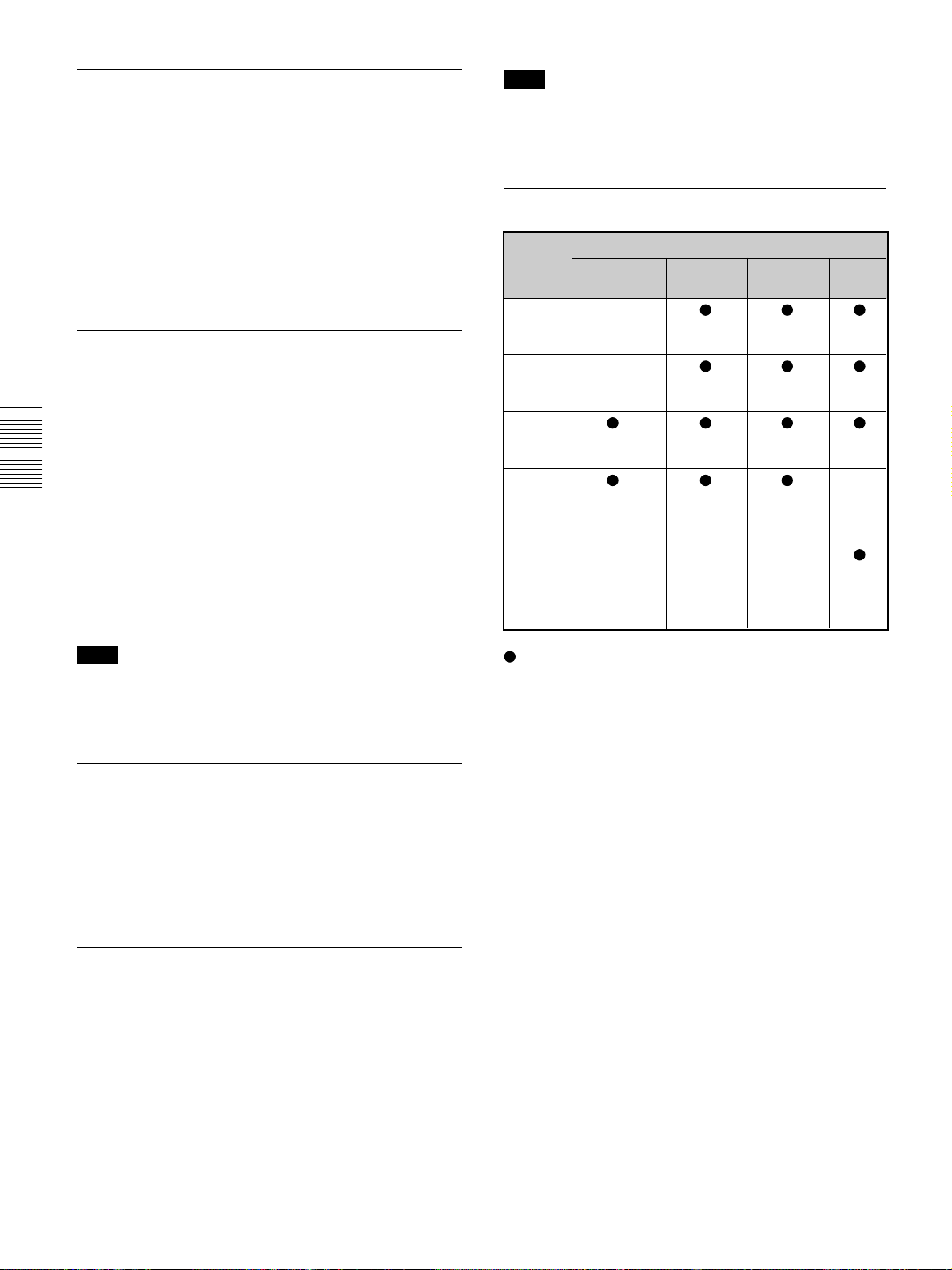
Warning on power connection
Use a proper power cord for your local power supply.
The United States, Continental UK, Ireland, Japan
Canada Europe Australia, New Zealand
Plug type VM0233 290B YP-12A COX-07 —
Female end VM0089 386A YC-13B COX-02 VM0310B YC-13
Cord type SJT SJT H05VV-F H05VV-F N13237/CO-228 VCTF
Rated Voltage & Current 10A/125V 10A/125V 10A/250V 10A/250V 10A/250V 7A/125V
Safety approval UL/CSA UL/CSA VDE VDE VDE DENTORI
1)
YP332
© 1999 - 2000 WESTTEK LLC. All Rights Reserved. WESTTEK and the WT Logo are registered
trademarks of WESTTEK, LLC.
The SONY VPL-Series projector contains materials owned by Sony and Sony suppliers, including
WESTTEK, LLC. Your purchase of the SONY VPL-Series projector gives you a limited right to use these
materials, solely as a part of the SONY VPL-Series projector and only as necessary to use the SONY VPL
Series projector in the manner described in the accompanying documentation. Your purchase of the SONY
VPL-Series projector does not transfer any ownership in these materials to you and you are forbidden to use
them for any purpose other than as part of the SONY VPL-Series projector. These materials are protected by
copyright law and international treaties any unauthorized use, reproduction or distribution of such materials, or
any portion of them, may result in severe civil and criminal penalties, and will be prosecuted to the maximum
extent permissible under law.
.........................................................................................................................................................................................................
1) Use the correct plug for your country.
3 (GB)
Page 4

4 (GB)
Page 5
Table of Contents
Overview
Setting up and projecting
Precautions ............................................................... 7 (GB)
Features..................................................................... 8 (GB)
Location and Function of Controls......................... 9 (GB)
Front......................................................................... 9 (GB)
Rear/Bottom............................................................. 9 (GB)
Control panel.......................................................... 10 (GB)
Connector panel ..................................................... 12 (GB)
Remote Commander .............................................. 13 (GB)
Installing the Projector........................................... 14 (GB)
Connecting.............................................................. 15 (GB)
Connecting with a Computer or a VCR................. 15 (GB)
Connecting with a 15k RGB/Component
Equipment......................................................... 16 (GB)
Connecting to LAN................................................ 16 (GB)
Selecting the Menu Language............................... 18 (GB)
Projecting ................................................................ 18 (GB)
Adjustments and settings using the menu
Using the MENU...................................................... 21 (GB)
The PICTURE CTRL Menu ..................................... 22 (GB)
The INPUT SETTING Menu .................................... 23 (GB)
The SET SETTING Menu ........................................ 25 (GB)
The INSTALL SETTING Menu ................................ 26 (GB)
Installation
Installation Example............................................... 28 (GB)
GB
English
Notes for Installation.............................................. 29 (GB)
Unsuitable Installation ........................................... 29 (GB)
Unsuitable Conditions for Use............................... 29 (GB)
5 (GB)
Page 6

Maintenance
Other
Maintenance............................................................ 30 (GB)
Replacing the Lamp ............................................... 30 (GB)
Cleaning the Air Filter ........................................... 31 (GB)
Troubleshooting ..................................................... 32 (GB)
Specifications ......................................................... 34 (GB)
Index ........................................................................ 37 (GB)
6 (GB)
Page 7

Precautions
Precautions
On safety
•Check that the operating voltage of your unit is
identical with the voltage of your local power
supply.
•Should any liquid or solid object fall into the cabinet,
unplug the unit and have it checked by qualified
personnel before operating it further.
•Unplug the unit from the wall outlet if it is not to be
used for several days.
•To disconnect the cord, pull it out by the plug. Never
pull the cord itself.
•The wall outlet should be near the unit and easily
accessible.
•The unit is not disconnected to the AC power source
(mains) as long as it is connected to the wall outlet,
even if the unit itself has been turned off.
•Do not look into the lens while the lamp is on.
•Do not aim the laser at people or not look into the
laser transmitter.
•Do not place your hand or objects near the
ventilation holes — the air coming out is hot.
•Be careful not to catch your fingers by the adjuster
when you lift up the projector. Do not push hard on
the top of the projector with the adjuster out.
•Be sure to grasp the both sides of the projector with
both your hands when carrying the projector.
On illumination
•To obtain the best picture, the front of the screen
should not be exposed to direct lighting or sunlight.
•Ceiling-mounted spot lighting is recommended. Use
a cover over fluorescent lamps to avoid lowering the
contrast ratio.
•Cover any windows that face the screen with opaque
draperies.
•It is desirable to install the projector in a room where
floor and walls are not of light-reflecting material. If
the floor and walls are of reflecting material, it is
recommended that the carpet and wall paper be
changed to a dark color.
On preventing internal heat build-up
After you turn off the power with the I / 1 key on the
Remote Commander or on the control panel, do not
disconnect the unit from the wall outlet while the
cooling fan is still running.
Caution
The projector is equipped with ventilation holes
(intake) on the bottom and ventilation holes (exhaust)
on the front. Do not block or place anything near these
holes, or internal heat build-up may occur, causing
picture degradation or damage to the projector.
On cleaning
•To keep the cabinet looking new, periodically clean
it with a soft cloth. Stubborn stains may be removed
with a cloth lightly dampened with a mild detergent
solution. Never use strong solvents, such as thinner,
benzene, or abrasive cleansers, since these will
damage the cabinet.
•Avoid touching the lens. To remove dust on the lens,
use a soft dry cloth. Do not use a damp cloth,
detergent solution, or thinner.
•Clean the filter at regular intervals every 300 hours.
On repacking
Save the original shipping carton and packing
material; they will come in handy if you ever have to
ship your unit. For maximum protection, repack your
unit as it was originally packed at the factory.
On LCD projector
The LCD projector is manufactured using highprecision technology. You may, however, see tiny
black points and/or bright points (red, blue, or green)
that continuously appear on the LCD projector. This is
a normal result of the manufacturing process and does
not indicate a malfunction.
Overview
7 (GB)
Page 8

Features
Features
High brightness, high picture quality
•Tilt installation (in front and rear)
You can install the projector by tilting it 90 degrees at
the rear or 90 degrees in front. You can use a mirror
for rear projection.
•High brightness
The high aperture ratio LCD panel with a microlens
and the 250 W UHP lamp provide high brightness
(light output 3500 ANSI lumen) and excellent
uniformity on the picture.
•High resolution
By adopting three 1.3-inch, approximately 790,000pixels XGA panels, this projector can project sharp
picture with the resolutions of 1024 × 768 pixels for
RGB input, and 750 horizontal TV lines for video
input.
•High picture performance
The DDE (Dynamic Detail Enhancer) technology,
newly and originally developed by Sony, enables
converting interlace format video signal to
progressive format, allowing you to obtain a detailed
picture. The technology also reproduces the film
sources in 2-3 Pull-Down format with smooth picture
movement.
The internal RGB enhancer provides sharper RGB
pictures. The 10-bit 3D Digital Gamma correction for
good picture uniformity is also provided.
Convenient and flexible setup
•Power zoom/power focus lens and the lens shift
function
The projector is equipped with a 1.3-times power
zoom and power focus lens, which allows you to
change the size of the projected image without having
to move the projector. The lens shift function enables
you to install the projector in a wide range of
locations, without worrying about trapezoid
distortion. Also, three optional lenses are available for
the projector, depending on your setup condition.
•Center positioned lens
The projector is designed to locate the lens in the
center of the unit. This enables an easy setup, as the
lens center aligns with the center of the screen.
•Twin stack installation
Thanks to the lens shift function, two projectors can
be stacked, which improves the brightness of the
image.
Multi scan compatibility
•DVI and 5BNC connectors
The projector has the DVI (Digital Visual Interface)
connector, the up-to-date digital input connector,
which allows you to connect to the digital or analog
RGB equipment equipped with the DVI output. The
5BNC input connectors allow you to connect to
workstation output high-resolution signals and to
connect to a computer from a long distance.
The projector has 44 preset data for input signals in
the memory, which allows you to project a clear
picture on the screen simply by connecting equipment
and pressing the APA (Auto Pixel Alignment) key.
•Accept various input signals
The projector accepts video signals of the composite,
S video and component, and can also display the 15k
1)
RGB, DTV, HDTV, VGA
, SVGA1), XGA1), SXGA
and UXGA1) (fV=60 Hz) signals.
•Scan converter built-in
The projector has a built-in scan converter which
converts the input signal within 1024 × 768 pixels.
•Compatible with six color systems
3.58, PAL, SECAM, NTSC 4.43
NTSC
2)
, PAL-M or
PAL-N color system can be selected automatically or
manually.
Other function
•Networking compatibility
The projector is equipped with a PC CARD slot and
ETHER connector, which allows you to connect to a
wired or wireless LAN.
For information on the networking function of this
projector, refer to the supplied Operating Instructions for
Networking.
1)
.........................................................................................................................................................................................................
1) VGA, SVGA, XGA, SXGA and UXGA are registered trademarks of the International Business Machines Corporation,
U.S.A.
2) NTSC4.43 is the color system used when playing back a video recorded on NTSC on an NTSC4.43 system VCR.
8 (GB)
Page 9
Location and Function of
Controls
Location and Function of Controls
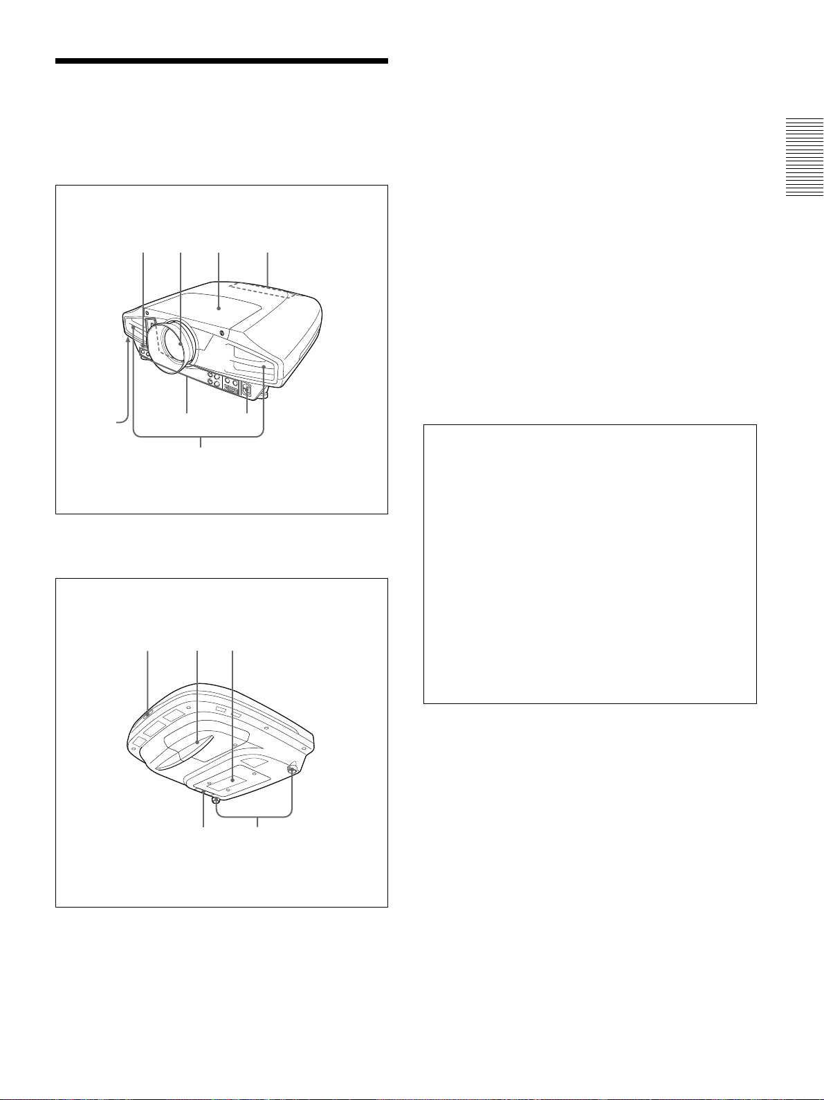
1 Front remote control detector
2 Lens
Remove the lens cap before projection.
Front
12 3 4
8
7
3 Lens cover
4 Control panel
For details, see “Control panel” on page 10 (GB).
5 AC IN socket
Connects the supplied AC power cord.
6 Connector panel
For details, see page 12 (GB).
7 Ventilation holes (exhaust)
8 Security lock
Connects to an optional security cable (Kensington’s).
56
The security lock corresponds to Kensington’s
MicroSaver
If you require further information, contact
Kensington
2855 Campus Drive
San Mateo, CA 94403
®
Security System.
Rear/Bottom
9q;qa
in North America
Phone: 800-235-6708
Fax: 800-247-1317
Outside North America
Phone: 847-541-9500
Home page address:
http://www.kensington.com/
9 Rear remote control detector
q; Lamp cover
qa Ventilation holes (intake)
qsqd
9 (GB)
Page 10
Location and Function of Controls
Notes
•Do not place anything near the ventilation holes as it
may cause internal heat build-up.
•Do not place your hand or objects near the
ventilation holes — the air coming out is hot.
qs Adjuster
Use the adjusters to keep the projector level if it is
installed on an uneven surface.
Adjust the height so that the projector becomes level.
The projector is raised by turning the adjusters
clockwise, or it is lowered by turning them
counterclockwise.
qd Air filter
To remove the air filter, pull it out horizontally with
this part.
For details, see “Cleaning the Air Filter” on page 31 (GB).
Note
Clean the air filter every 300 hours to ensure
optimal performance.
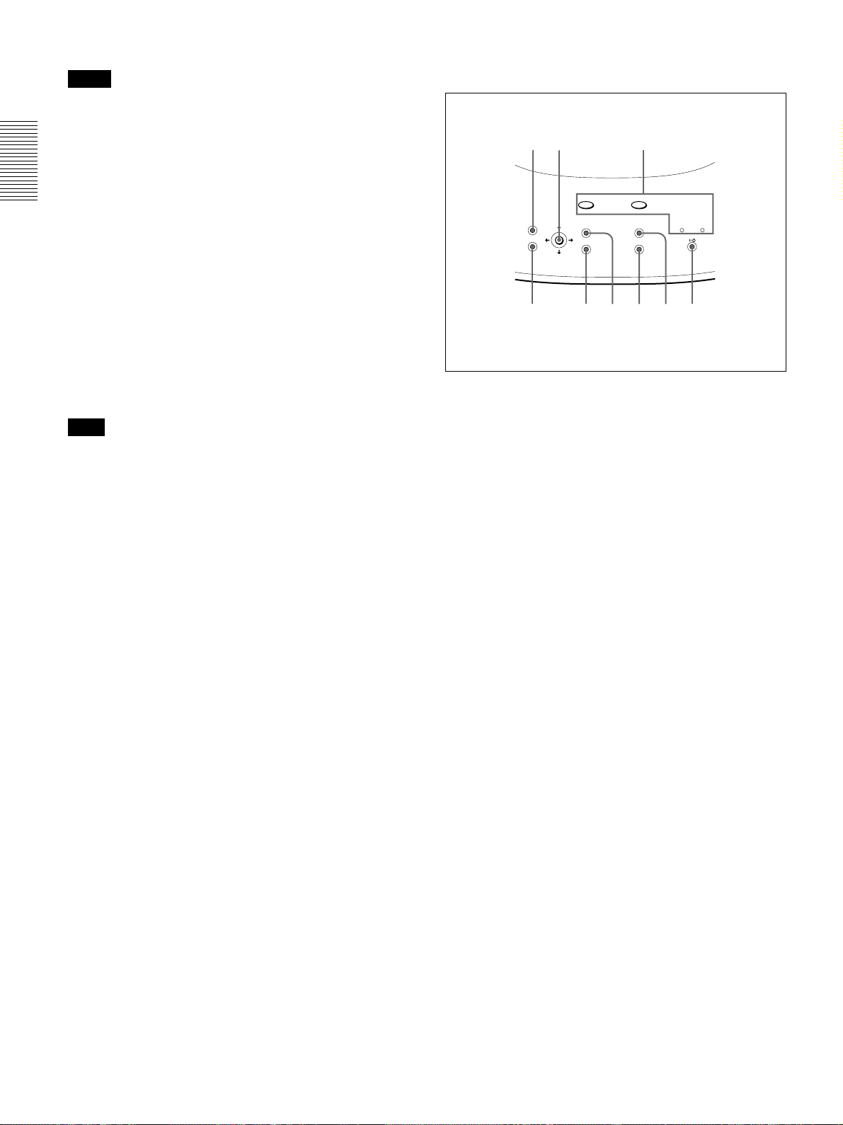
Control panel
12 3
TEMP/FAN
LENS CONTROL
RESET
MENU
ENTER
1 LENS CONTROL key
Enters the focus, zoom or shift adjustment mode. Next
adjust them using the arrow keys. Each time you press
the key, the mode changes to LENS FOCUS, LENS
ZOOM and LENS SHIFT in order. The mode
currently selected is displayed on the screen.
LENS FOCUS: Enters the focus adjustment mode.
Next adjust the focus using the arrow keys. Press
the M or , key to focus on a picture further
back, and the m or < key to focus on a forward
picture. You cannot select LENS FOCUS when
you attach the optional lens.
LENS ZOOM: Enters the zoom adjustment mode.
Next adjust the picture size using the arrow keys.
Press the M or , key to enlarge the picture size,
and the m or < key to reduce it. You cannot
select LENS ZOOM when you attach the optional
lens.
LENS SHIFT: Enters the shift adjustment mode.
Next adjust the vertical position of the picture
using the arrow keys. Press the M or , key to
move the picture upward, and the m or < key to
move it downward.
LAMP/COVER
INPUT
APA
POWER SAVING ON/STANDBY
456789
10 (GB)
2 Arrow keys (M/m/</,)
Used to adjust focus, zoom and shift, or to move the
cursor or make various adjustments in the menu.
Page 11

Location and Function of Controls
3 Indicators
TEMP (Temperature)/FAN
• Lights up when temperature inside the projector
becomes unusually high.
• Flashes when the fan is broken.
LAMP/COVER
• Lights up when the lamp has reached the end of
its life or becomes a high temperature.
• Flashes when the lamp cover or air filter is not
secured firmly.
POWER SAVING
Lights up when the projector is in the power
saving mode. When POWER SAVING in the
SET SETTING menu is set to ON, the projector
goes into the power saving mode if no signal is
input for 10 minutes. Although the lamp goes out,
the cooling fan keeps running. In the power
saving mode, any key does not function for the
first 40 seconds. The power saving mode is
canceled when a signal is input or any key is
pressed.
5 INPUT key
Selects the input signal. Each time you press the key,
the input signal switches as follows:
B INPUT-A B INPUT-B B INPUT-C
S-VIDEO b VIDEO b
INPUT C is not displayed when INPUT C FUNC. is
set to OFF in the INSTALL SETTING menu.
6 APA (Auto Pixel Alignment) key
Adjusts a picture to be projected clearest
automatically while a signal from the computer is
input. Adjusts the shift (up/down and left/right) at the
same time automatically. (Only when inputting a
RGB (analog) signal from the computer).
Note
Press the APA key when the full image is displayed
on the screen. If there are black edges around the
image, the APA function will not function properly
and the image may extend beyond the screen.
ON/STANDBY
• Lights in red when the AC power cord is
plugged into the wall outlet. Once in the
standby mode, you can turn on the projector
I / 1
with the
key.
• Lights in green when the power is turned on.
• Flashes in green while the cooling fan runs after
I / 1
turning off the power with the
key. The
fan runs for about 120 seconds after turning off
the power.
The ON/STANDBY indicator flashes quickly
for the first 40 seconds. During this time, you
cannot turn the power back on with the
I / 1
key.
For details on the LAMP/COVER and the TEMP/FAN
indicators, see page 33 (GB).
4 I / 1 (on / standby) key
Turns on the projector when the projector is in the
standby mode. The ON/STANDBY indicator lights in
green when the power is turned on.
1
When turning off the power, press the I /
key
twice following the message on the screen, or press
and hold the key for about one second.
For details on steps for turning off the power, see “To turn
off the power” on page 20 (GB).
7 MENU key
Displays the on-screen menu. Press again to clear the
menu.
8 ENTER key
Enters the settings of items in the menu system.
9 RESET key
Resets the value of an item back to its factory preset
value. This key functions when the menu or a setting
item is displayed on the screen.
11 (GB)
Page 12
Location and Function of Controls
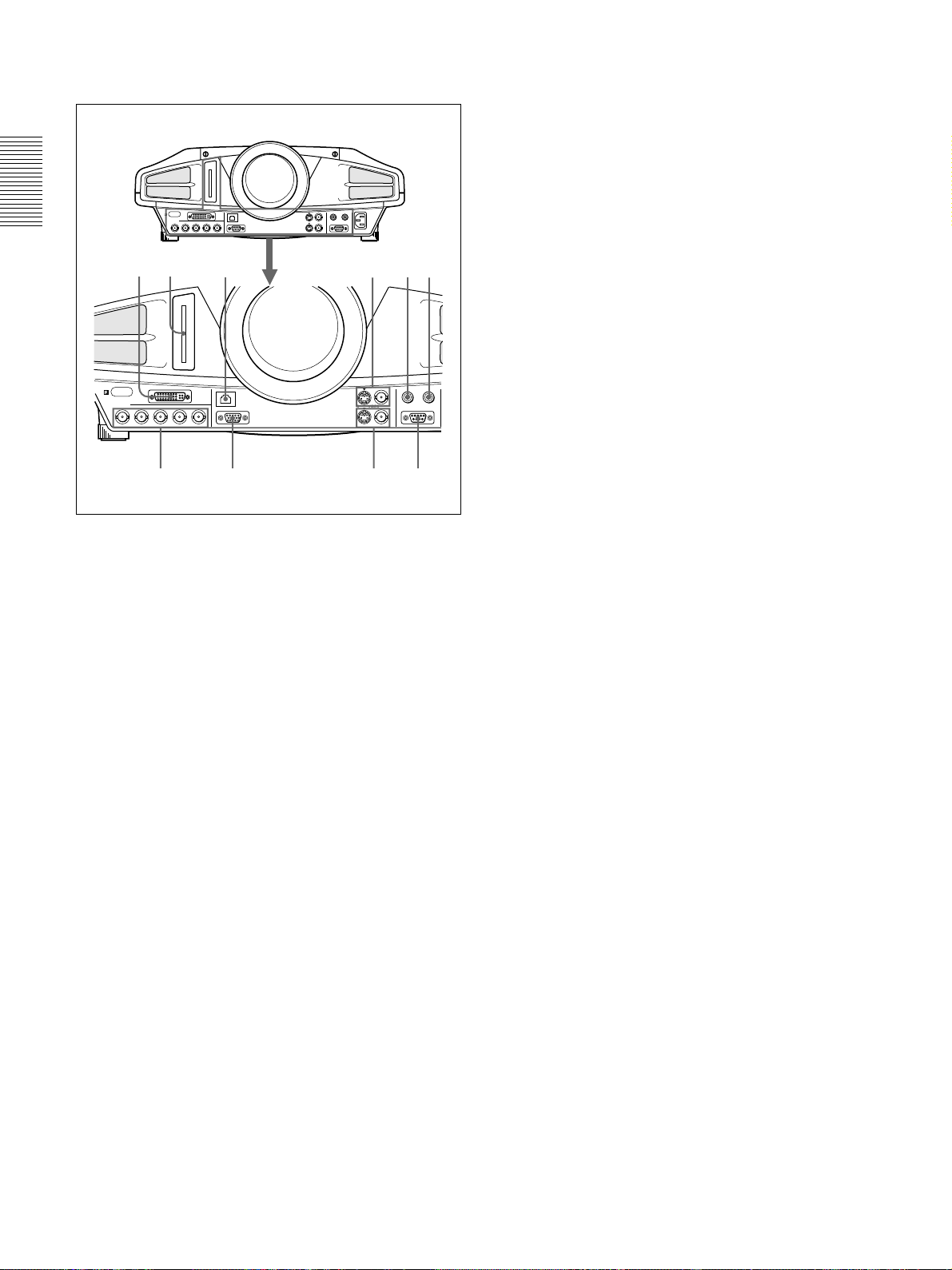
Connector panel
Front
32
INPUT A
R
B/B-Y/P
BG/Y SYNC/HD
R/R-Y/P
1
1 INPUT A 5BNC connectors (R/R-Y/PR, G/Y, B/
B, SYNC/HD, VD connectors) (BNC type)
B-Y/P
Connect to a high-resolution computer or VCR where
signals are transmitted long distances; for example,
when the projector is installed on the ceiling.
According to the connected equipment, computer,
component (R-Y/Y/B-Y), HDTV or DTV signal is
selected.
2 INPUT B RGB (DVI) connector
Connect to equipment equipped with the DVI output
(digital or analog RGB) using a commercially
available DVI cable.
4567
PLUG IN POWER
TRIG
INPUT B
RGB (DVI)
VD
0
INPUT C
ETHER
MONITOR OUT
VIDEO IN
VIDEO OUT
S VIDEO VIDEO
CONTROL S
RS-232C
89
6 TRIG (trigger output) jack (monaural
minijack)
The signal is transmitted from this jack to the
connected equipment whether the projector is on or
off. (This is not a power source for external
equipment.) Approximately 12 V DC signal is output
when the projector power is on. The signal is 0 volt
level output when the projector power is off.
7 CONTROL S/PLUG IN POWER (DC 5V
output) jack (stereo minijack)
Connects to the control S out jacks of the Sony equipment.
Connects to the CONTROL S OUT jack on the supplied
Remote Commander when using it as a wired Remote
Commander. In this case, you do not need to install the
batteries in the Remote Commander, since the power is
supplied from this jack.
8 RS-232C connector (D-sub 9-pin, female)
Connects to a computer to operate the projector from
the computer.
9 VIDEO OUT connectors
S VIDEO (mini DIN 4-pin): Used as loop-through
output via the S VIDEO IN connector.
VIDEO (BNC type): Used as loop-through output
via the VIDEO IN connector.
q; MONITOR OUT connector (HD D-sub 15-pin,
female)
Connects to the monitor input connector on the
monitor. Outputs signals from the selected channel in
the INPUT A (5BNC) or INPUT B (DVI) connector.
This connector does not output any signals from the
DVI connector if the input signal is digital.
3 INPUT C PC CARD slot (Type II)
A wireless LAN PC card or PC memory card can be
attached according to your requirement.
For details, see “Installing a PC card” on page 16 (GB).
4 INPUT C ETHER connector (10BASE-T)
Connect to a computer on the same LAN with the
LAN cable when you use the networking function of
this projector.
5 VIDEO IN connectors
Connect to external video equipment such as a VCR.
S VIDEO (mini DIN 4-pin):
Connects to the S video
output (Y/C video output) on video equipment.
VIDEO (BNC type): Connects to the composite
video output.
12 (GB)
Page 13
Location and Function of Controls
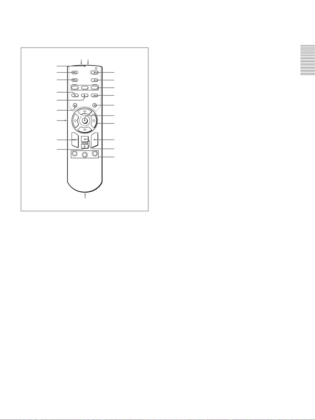
Remote Commander
The keys which have the same names as those on the
control panel function identically.
wswd
wa
w;
ql
qk
qj
qh
qg
qf
qd
COMMAND
OFF · · ON
PJ · · NETWORK
FOCUS
INPUT
MENU/
TAB
+
–
D ZOOM
13
LENS CONTROL
ZOOM
MUTING
PIC
ENTER
RESET/
ESCAPE
2
FUNCTION
I /
APA
SHIFT
FREEZE
LASER
R
CLICK
1
2
3
4
5
6
7
8
9
0
0 FUNCTION 1/2/3 keys
Functions when the PJ/NETWORK select switch is set
to NETWORK.
When the INPUT C window is displayed on the
projector, you can start an application by just pressing
a FUNCTION key. To use this function, allocate an
application to a FUNCTION key. Allocation to the
FUNCTION 3 key is set to the keyboard software
display.
For details on how to allocate an application to the
FUNCTION keys, refer to the Operating Instructions for
Networking.
qa Strap holder
Attaches a strap.
qs CONTROL S OUT jack (stereo minijack)
Connects to the CONTROL S IN jack on the projector
with the connecting cable (not supplied) when using
the Remote Commander as a wired one. In this case,
you do not need to install the batteries since the power
is supplied via the CONTROL S IN jack on the
projector.
qa,qs
Notes on laser beam
•Do not look into the laser transmitter.
•Do not aim the laser at people.
I / 1
1
2 APA (Auto Pixel Alignment) key
3 LENS CONTROL FOCUS/ZOOM/SHIFT keys
4 FREEZE key
Used to freeze the picture projected. To cancel the
freezed picture, press the key again.
5 LASER key
Emits laser beam from the laser transmitter while you
keep this key pressed.
6 Mouse
This functions as the mouse in the INPUT C window
of this projector when the PJ/NETWORK select
switch is set to NETWORK.
7 Arrow keys (M/m/</,)
8 R (right) CLICK key
When the PJ/NETWORK select switch is set to
NETWORK, this key functions as the right button on
the mouse in the INPUT C window of this projector.
key
qd RESET/ESCAPE key
When the PJ/NETWORK select switch is set to
PJ: Functions as the RESET key.
When the PJ/NETWORK select switch is set to
NETWORK: Functions as the ESCAPE key of
the keyboard when the INPUT C window is
displayed.
qf D ZOOM +/– key
Enlarges the image at a desired location on the screen.
+: Pressing the + key once displays the icon. This
icon indicates the point you want to enlarge. Use
an arrow key (M/m/</,) to move the icon to
the point to be enlarged. Press the + key
repeatedly until the image is enlarged to your
requirements.
–: Pressing the – key reduces an image that has been
enlarged with the D ZOOM + key.
qg L (left) CLICK key
When the PJ/NETWORK select switch is set to
NETWORK, this key functions as the left button on a
mouse in the INPUT C window of the projector.
qh MENU/TAB key
When the PJ/NETWORK select switch is set to
PJ: Functions as the MENU key.
When the PJ/NETWORK select switch is set to
NETWORK: Functions as the TAB key of the
keyboard when the INPUT C window is
displayed.
9 ENTER key
13 (GB)
Page 14
Location and Function of Controls / Installing the Projector
qj PIC MUTING key
Cuts off the picture. Press again to restore the picture.
qk INPUT key
ql PJ/NETWORK select switch
To use the Remote Commander for network
operations, set the switch to NETWORK. Set the
switch to PJ to use the Remote Commander for
normal operations other than networking.
w; COMMAND ON/OFF switch
When this switch is set to OFF, no key on the Remote
Commander function. This saves the battery power.
wa Transmission indicator
Lights up when you press a key on the Remote
Commander.
This indicator does not light up when you use the laser
pointer.
ws Infrared transmitter
wd Laser transmitter
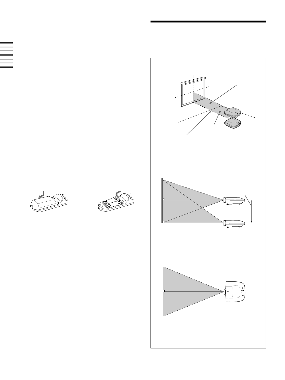
Installing the Projector
This section describes the installation arrangements
for installing the projector.
Horizontal center
of the screen
Vertical
center of
the screen
Installation
area
Projection distance
The distance between the lens and the screen
varies depending on the screen size.
Refer to the chart on page 28 (GB).
Install the projector so
that the tip of the lens
is within this area.
Battery installation
1 Push and slide to open the lid, then install the two
size AA (R6) batteries (supplied) with the correct
polarity.
Be sure to install
the battery from
the # side.
2 Replace the lid.
Notes on batteries
•Make sure that the battery orientation is correct when
inserting batteries.
•Do not mix an old battery with a new one, or
different types of batteries.
•If you will not use the Remote Commander for a
long time, remove the batteries to avoid damage
from battery leakage. If batteries have leaked,
remove them, wipe the battery compartment dry and
replace the batteries with new ones.
Adjust the vertical and horizontal positioning of the projector.
Vertical positioning (side view)
Adjustable
shift range
Screen
You can adjust the angle of projection by performing the shift
adjustment (page 19 (GB)). Install the projector so that the
center of the lens is between the bottom edge of the screen
and the center of the screen.
Horizontal positioning (top view)
Notes on Remote Commander operation
•Make sure that there is nothing to obstruct the
infrared beam between the Remote Commander and
the remote control detector on the projector.
•The operation range is limited. The shorter the
distance between the Remote Commander and the
projector is, the wider the angle within which the
commander can control the projector.
14 (GB)
Center of the projector
Screen
Adjust the horizontal positioning of the projector so that the
center of the lens is aligned with the horizontal center of the
screen.
Page 15
Connecting
Connecting
Computer
When making connections, be sure to:
•turn off all equipment before making any
connections.
•use the proper cables for each connection.
•insert the plugs of the cables properly; plugs that are
not fully inserted often generate noise. When pulling
to DVI
output
out a cable, be sure to pull it out from the plug, not
the cable itself.
DVI cable
(not supplied)
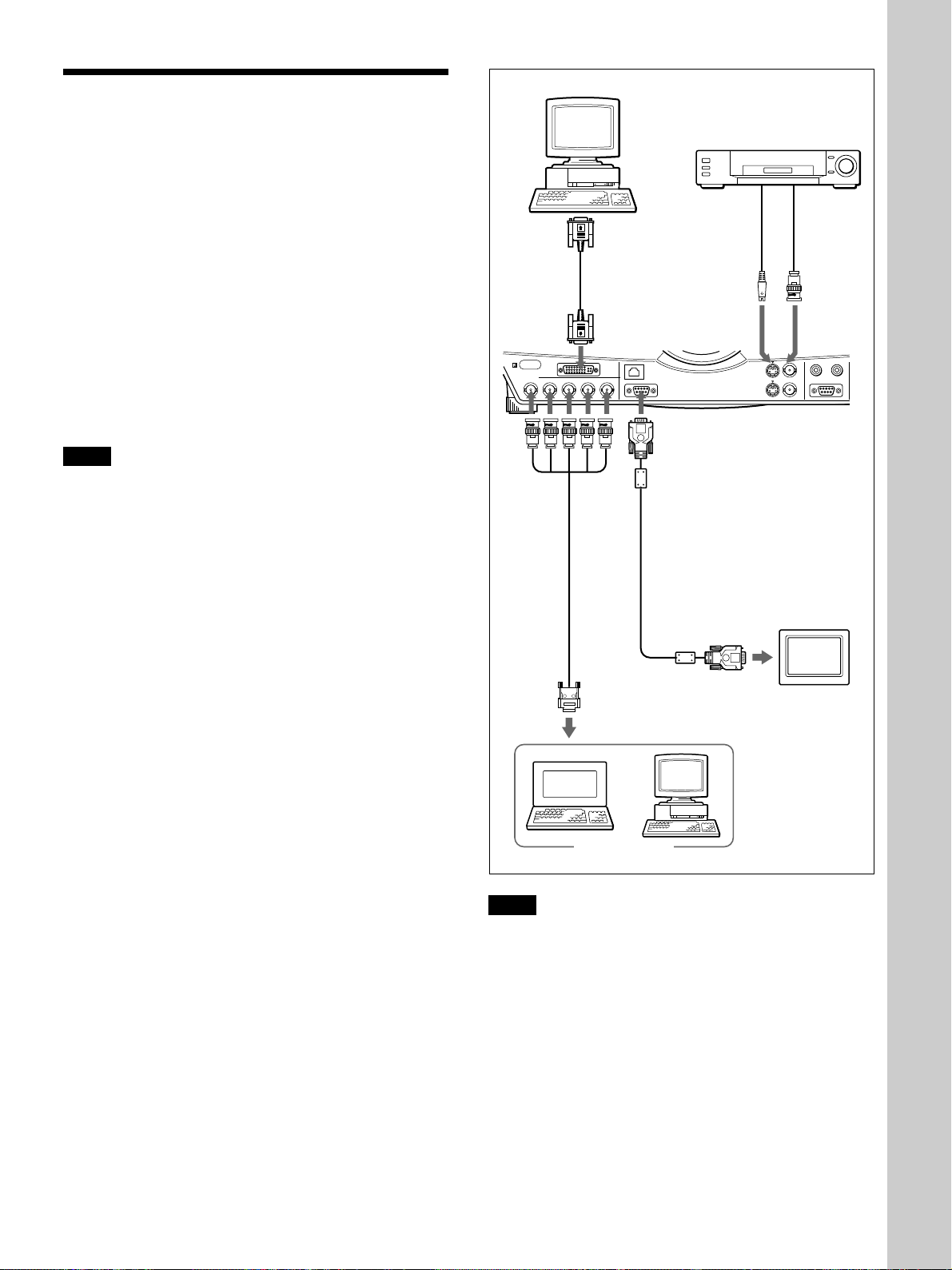
Connecting with a Computer or a
VCR
This section describes how to connect the projector to
INPUT A
R
G/Y SYNC/HD
a computer or video equipment.
R/R-Y/P
Also refer to the instruction manual of equipment to
be connected.
Notes
•This unit accepts the VGA, SVGA, XGA, SXGA or
UXGA (60 Hz) signals. However, we recommend
you to set the output signal of your computer to the
XGA.
•If you set your computer, such as a notebook type
1)
IBM PC/AT
compatible, to output the signal to
both the display of your computer and the external
monitor, the picture of the external monitor may not
appear properly. In such cases, set the output mode
of your computer to output the signal to only the
SMF-400
Monitor
cable
(5BNC
y HD Dsub 15pin) (not
supplied)
to monitor
out
external monitor.
For details, refer to the operating instructions supplied
with your computer.
•This projector complies with DDC1 and DDC2B
(Plug & Play). (DDC1 and DDC2B are the Display
Data Channel (DDC
TM) 2)
standard in the VESA
standard.) When connecting a DDC1 host system,
the projector synchronizes with V.CLK that follows
the VESA standard and outputs EDID (Extended
Display Identification Data) to the data line. When
connecting a DDC2B host system, the projector
automatically switches to the appropriate
communication mode.
The INPUT B RGB (DVI) connector complies with
the VESA DDC2B. If your computer or graphics
board is compatible with DDC, turn on the power of
the equipment as follows:
1 According to the input signal, set INPUT-B TERM.
in the SET SETTING menu to PC ANALOG or PC
DIGITAL.
2 Connect the projector to the computer with the DVI
cable.
3 Turn on the power of the projector.
4 Boot up the computer.
.........................................................................................................................................................................................................
Notes
• Set INPUT-A in the SET SETTING menu to
COMPUTER when you connect the computer to the
INPUT A connector.
For details, see page 26 (GB).
• When connecting a Macintosh3) computer equipped
with video output connector of a type having two
rows of pins to the INPUT A connector, use a
commercially available plug adaptor.
• Select PC DIGITAL or PC ANALOG using INPUTB TERM. in the SET SETTING menu depending on
the signal input.
For details, see page 26 (GB).
B/B-Y/P
B
Computer
INPUT B
INPUT C
RGB (DVI)
ETHER
VD
SMF-410 Monitor cable
(HD D-sub 15-pin y HD
D-sub 15-pin) (not
supplied)
VCR
to S video
output
S-Video cable
(not supplied)
MONITOR OUT
to monitor input
to video
output
Video
cable (not
supplied)
PLUG IN POWER
TRIG
VIDEO IN
S VIDEO VIDEO
VIDEO OUT
Front of the projector
CONTROL S
RS-232C
Monitor
Setting up and projecting
1) IBM and PC/AT are a trademark and a registered trademark of International Business Machines Corporation, U.S.A.
2) DDCTM is a registered trademark of the Video Electronics Standard Association.
3) Macintosh is a registered trademark of Apple Computer Inc.
15 (GB)
Page 16
Connecting
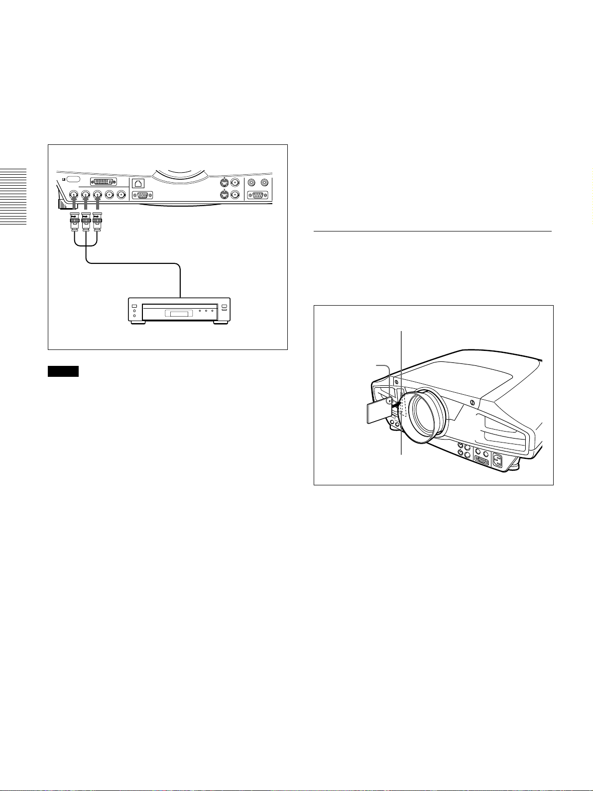
Connecting with a 15k RGB/
Component Equipment
This section describes how to connect the projector
with a 15k RGB/component equipment.
Also refer to the instruction manuals of the equipment
to be connected.
Front of the projector
PLUG IN POWER
TRIG
INPUT A
R/R-Y/P
R
RGB (DVI)
B/B-Y/PBG/Y SYNC/HD
VD
Monitor cable
(not supplied)
ETHER
MONITOR OUT
15k RGB/component equipment
VIDEO IN
S VIDEO VIDEO
VIDEO OUT
to RGB/component
output
INPUT B
INPUT C
Notes
• Set the aspect ratio using ASPECT in the INPUT
SETTING menu according to the input signal.
For details, see page 24 (GB).
•Select the input signal using INPUT-A in the SET
SETTING menu.
For details, see page 26 (GB).
•Use the composite sync signal when you input the
external sync signal from 15k RGB/component
equipment.
Connecting to a HDTV 1035/60i
Since the screen ratio of a high definition image is
16:9 and 576 lines are displayed in the vertical
direction, the image displayed is not a highdefinition image.
CONTROL S
RS-232C
Connecting to LAN
This projector is compatible with networking.
Installing a wireless LAN PC card or using the
ETHER connector enables you to connect the
projector to a wireless or wired LAN. You can also
install a PC memory card.
This section describes how to connect to LAN and
how to install a PC card.
Whenever you connect the projector to LAN, set
INPUT C FUNC. in the INSTALL SETTING menu
to ON.
For details, see page 27 (GB).
Installing a PC card
When you use a wireless LAN PC card or memory
card, insert the card into the INPUT C PC CARD
slot.
Open the lid of the slot, then insert the PC card
to the INPUT C PC CARD slot
Insert the card
with the arrow
mark facing
toward the slot.
PC card
The eject button pops out
when inserting.
To remove the PC card from the slot, press the eject
button.
16 (GB)
Page 17
Connecting
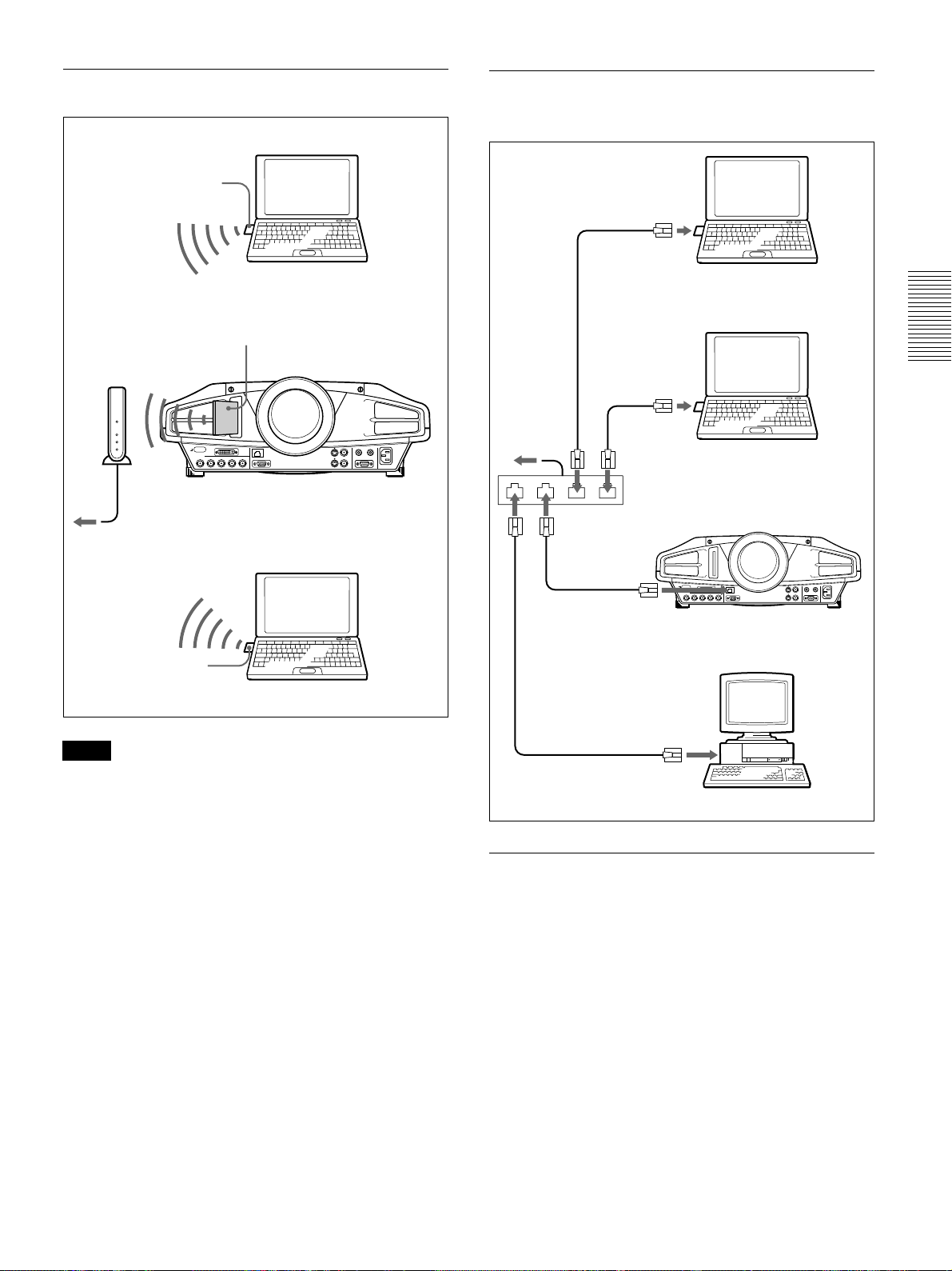
Connection using a wireless LAN PC card
Wireless LAN PC card
(IEEE802.11b compliant)
(recommended)
Computer
Wireless LAN
access point
(IEEE802.11b
compliant)
(recommended)
to Hub/router
Wireless LAN PC card
(IEEE802.11b compliant) (specified)
PC CARD
Front of the projector
Connection using the INPUT C ETHER
connector
LAN cable
Computer
LAN cable
to router
Hub
LAN cable
Computer
Front of the projector
PC CARD
Wireless LAN PC card
(IEEE802.11b compliant)
(recommended)
Computer
Notes
•For details on the recommended PC card or wireless
LAN access point, see the attached “Recommended
PC card/wireless LAN access point.”
•When you use LAN, you must set the IP address. For
details of setting IP address, etc., see the supplied
“Operating Instructions for Networking.”
INPUT C ETHER
connector
LAN cable
Computer
Installing a PC memory card
If you store the file created with Microsoft
PowerPoint
INPUT C PC CARD slot, you can run a presentation
without connecting a computer.
For attaching and removing the PC memory card, see
“Installing a PC card” on page 16 (GB).
For details on the recommended PC card, see the attached
“Recommended PC card/wireless LAN access point.”
1)
in a memory card and insert it into the
.........................................................................................................................................................................................................
1) PowerPoint is a registered trademark of Microsoft Corporation in the United States and/or other countries.
17 (GB)
Page 18

Selecting the Menu Language/Projecting
Selecting the Menu Language
You can select the language for displaying in the
menu and other on screen displays from 7 languages.
The factory setting is ENGLISH.
4,5,6 3 2
TEMP/FAN
LENS CONTROL
RESET
MENU
ENTER
1
1 Plug the AC power cord into the wall outlet.
2 Press the I /
1
key to turn on the power.
3 Press the MENU key.
LAMP/COVER
INPUT
APA
POWER SAVING ON/STANDBY
Projecting
4,7
4–7
LENS CONTROL
RESET
4,6
APA key
TEMP/FAN
MENU
ENTER
5
3
COMMAND
OFF · · ON
PJ · · NETWORK
LENS CONTROL
FOCUS
INPUT
MENU/
TAB
ZOOM
MUTING
PIC
3
LAMP/COVER
I /
APA
SHIFT
FREEZE
LASER
INPUT
APA
ON/STANDBY
indicator
2
POWER SAVING ON/STANDBY
Rear remote
control detector
2
APA key
7
The menu display appears.
4 Press the M or m key to select the SET SETTING
menu, then press the , or ENTER key.
The SET SETTING menu appears.
SET SETTING
STATUS: ON
INPUT -B TERM.
INPUT-A: COMPUTER
AUTO INPUT SEL
LANGUAGE
POWER SAVING
IR RECEIVER
: PC DIGITAL
: OFF
: ENGLISH
: OFF
: FRONT&REAR
INPUT-A
5 Press the M or m key to select LANGUAGE, then
press the , or ENTER key.
6 Press the M or m key to select a language, then
press the < or ENTER key.
The menu changes to the selected language .
To clear the menu display
Press the MENU key.
The menu display disappears automatically if no key
is pressed for one minute.
4–7
+
–
D ZOOM
13
ENTER
RESET/
ESCAPE
2
FUNCTION
CLICK
R
1 After all equipment is connected completely, plug
the AC power cord into the wall outlet.
The ON/STANDBY indicator lights in red and the
projector goes into the standby mode.
2 Press the I /
1
key to turn on the projector.
The ON/STANDBY indicator lights in green.
3 Turn on equipment connected to the projector.
Press the INPUT key to select the input source.
18 (GB)
Page 19
Projecting
INPUT-A:Selects video signal input from the
INPUT A connector.
INPUT-B: Selects video signal input from the
INPUT B connector.
INPUT-C: Selects to display the Windows CE
window.
VIDEO: Selects video signal input from the
VIDEO (VIDEO IN) jack.
S-VIDEO:Selects video signal input from the S
VIDEO (VIDEO IN) jack.
4 Press the FOCUS key then the M or m key on the
Remote Commander to adjust the focus.
“LENS FOCUS” appears on the screen during
adjustment.
5 Press the ZOOM key then the M or m key on the
Remote Commander to adjust the picture size.
“LENS ZOOM” appears on the screen during
adjustment.
6 Press the FOCUS key and arrow keys on the
Remote Commander to adjust the focus again.
7 Press the SHIFT key then the M or m key on the
Remote Commander to adjust the vertical position
of the picture.
To get the clearest picture
You can get the suitable picture when a signal from
the computer is input. Press the APA key.
The picture is automatically adjusted to be projected
clearest.
Notes
•Adjust the signal when the still picture is displayed
on the screen.
•Press the APA key when the full image is displayed
on the screen. If there are black edges around the
image, the APA function will not function properly
and the image may extend beyond the screen.
•If you switch the input signal or re-connect a
computer, press the APA key again to get the
suitable picture.
•“ADJUSTING” appears on the screen. To restore the
original screen, press the APA key again during the
adjustment.
•“Complete!” appears on the screen when the picture
is adjusted properly. The picture may not be adjusted
properly depending on the kinds of input signals.
•Adjust the items in the INPUT SETTING menu
when you adjust the picture manually.
For details, see page 23 (GB).
To correct the trapezoid
“LENS SHIFT” appears on the screen during
adjustment.
Note on focus and zoom adjustments
If the optional VPLL-ZM101, VPLL-ZM31 or VPLLFM21 lens is installed, perform the focus and zoom
adjustments manually.
To use the keys on the control panel for
focus, zoom and shift adjustments
Press the LENS CONTROL key repeatedly to display
the adjustment mode you want. Each press changes
the mode, “LENS FOCUS,” “LENS ZOOM” and
“LENS SHIFT” in this order. Then press the arrow
keys to adjust.
Note
Looking into the lens when projecting may cause
injury to your eyes.
Cut off the picture
When the projecting image is a trapezoid, perform the
shift adjustment with the SHIFT key.
If the image is still a trapezoid, correct it in DIGIT
KEYSTONE in the INSTALL SETTING menu.
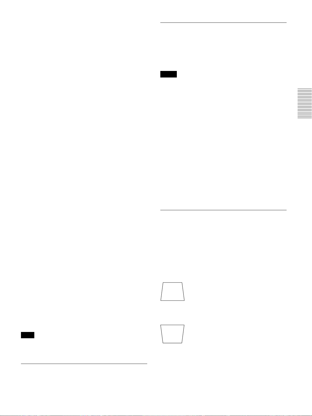
When the base edge is longer than the upper
edge as shown in the figure below:
Set the value to negative.
When the upper edge is longer than the base
edge as shown in the figure below:
Set the value to positive.
For details on “DIGIT KEYSTONE,” see page 27 (GB).
Press the PIC MUTING key on the Remote
Commander. To restore the picture, press the PIC
MUTING key again.
19 (GB)
Page 20
Projecting
To turn off the power
1 Press the I /
“Power OFF?” appears on the screen.
Note
The message will disappear if you press any key
except the I /
key for five seconds.
2 Press the I /
The ON/STANDBY indicator flashes in green and
the fan continues to run for about 120 seconds to
reduce the internal heat. Also, the ON/STANDBY
indicator flashes quickly for the first 40 seconds.
During this time, you will not be able to turn the
power back on with the I /
1
key.
1
key, or if you do not press any
1
key again.
1
key.
3 Unplug the AC power cord from the wall outlet
after the fan stops running and the ON/STANDBY
indicator lights in red.
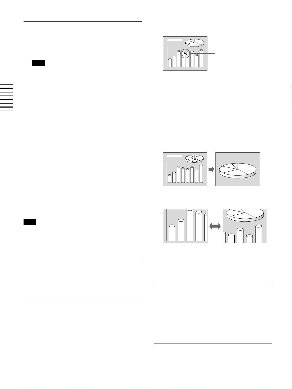
The Digital Zoom icon appears in the center of the
image.
Digital Zoom icon
2 Move the icon to the point on the image you want
to enlarge. Use the arrow keys (M/m/</,) to
move the icon.
3 Press the D ZOOM + key again.
The image where the icon is located is enlarged.
The enlargement ratio is displayed on the screen
for a few seconds.
By pressing the + key repeatedly, the image size
increases. (ratio of enlargement: max. 4 times)
When you cannot confirm the on-screen
message
When you cannot confirm the on-screen message in a
certain condition, you can turn off the power by
1
holding the I /
Note
Do not unplug the AC power cord while the
fan is still running; otherwise, the fan will
stop although the internal heat is still high,
leading to breakdown of the projector.
key for about one second.
About the air filter cleaning
Clean the air filter every 300 hours to ensure
optimal performance.
To enlarge the image (Digital Zoom
function)
You can enlage the point on the image you select.
This function works only when a signal from a
computer (except for UXGA) is input.
Use the arrow keys (M/m/</,) to scroll the
enlarged image.
To return the image back to its original size
Press the D ZOOM – key. Just pressing the RESET
key returns the image back to its original size
immediately.
To freeze the image projected (Freeze
function)
Press the FREEZE key. “FREEZE” appears when the
key is pressed. This function works only when a
signal from a computer (except for UXGA) is input.
To restore the original screen, press the FREEZE key
again.
1 Press the D ZOOM + key on the Remote
Commander.
20 (GB)
To use the Laser Pointer function
Press the LASER key on the Remote Commander.
The laser pointer appears. The pointer is helpful in
indicating a particular point on the screen.
Page 21

Using the MENU
Using the MENU
The projector is equipped with an on-screen menu for
making various adjustments and settings.
Note
Before operation, confirm that the PJ/NETWORK
select switch on the Remote Commander is set to PJ.
If it is set to NETWORK, the menu display will not
appear even when you press the MENU key on the
Remote Commander.
To select the language used in the menu, see page
26 (GB).
1 Press the MENU key.
The menu display appears.
The menu presently selected is shown as a yellow
button.
PICTURE CTRL
CONTRAST: 80
BRIGHT: 50
RGB ENHANCER:
GAMMA MODE:
COLOR TEMP:LOW
30
GRAPHICS
INPUT-A
To clear the menu
Press the MENU key.
The menu display disappears automatically if no key
is pressed for one minute.
To reset items that have been adjusted
Press the RESET key.
“Complete!” appears on the screen and the settings
appearing on the screen will be reset to their factory
preset values.
Items that can be reset are:
•“CONTRAST”, “BRIGHT”, “COLOR”, “HUE”,
“SHARP” and “RGB ENHANCER” in the
PICTURE CTRL menu.
•“DOT PHASE”, “SIZE H” and “SHIFT” in the
INPUT SETTING menu.
•“DIGIT KEYSTONE” in the INSTALL SETTING
menu.
About the memory of the settings
The settings are automatically stored in the projector
memory.
Adjustments and settings using the menu
2 Use the M or m key to select a menu, then press
the , or ENTER key.
The selected menu appears.
Menus Setting items
SET SETTING
STATUS: ON
INPUT-B
INPUT-A: COMPUTER
AUTO INPUT SEL:
POWER SAVING:
IR RECEIVER:
TERM.
LANGUAGE
: PC DIGITAL
OFF
: ENGLISH
OFF
FRONT&REAR
INPUT-A
3 Select an item.
Use the M or m key to select the item, then press
the , or ENTER key.
4 Make setting or adjustment on an item.
For details on setting individual items, see the relevant
menu pages.
When no signal is input
When there is no input signal, “NO INPUT–Cannot
adjust this item.” appears on the screen, and each item
cannot be adjusted.
About the menu display
You can set the display position of the menu, intensity
of the background picture and tone of the menu items
as you like.
For details, see page 27 (GB).
21 (GB)
Page 22
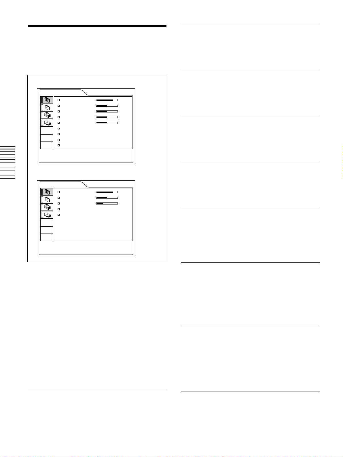
The PICTURE CTRL Menu
The PICTURE CTRL Menu
The PICTURE CTRL (control) menu is used for
adjusting the picture.
Unadjustable items depending on the input signal are
not displayed in the menu.
When the video signal is input
PICTURE CTRL
CONTRAST: 80
BRIGHT: 50
COLOR: 50
HUE: 50
SHARP: 50
D.PICTURE: ON
COLOR TEMP:LOW
COLOR SYS: AUTO
DDE: FILM
When the RGB signal is input
PICTURE CTRL
CONTRAST: 80
BRIGHT: 50
RGB ENHANCER:
GAMMA MODE:
COLOR TEMP:LOW
30
GRAPHICS
VIDEO
INPUT-A
BRIGHT
Adjusts the picture brightness.
The higher the setting, the brighter the picture.
The lower the setting, the darker the picture.
COLOR
Adjusts color intensity.
The higher the setting, the greater the intensity.
The lower the setting, the lower the intensity.
HUE
Adjusts color tones.
The higher the setting, the picture becomes greenish.
The lower the setting, the picture becomes purplish.
SHARP
Adjusts the picture sharpness.
The higher the setting, the sharper the picture.
The lower the setting, the softer the picture.
RGB ENHANCER
Operation
1. Select an item
Use the M or m key to select the item, then press the
, or ENTER key.
2. Adjust an item
• When changing the adjustment level:
To increase the number, press the M or , key.
To decrease the number, press the m or < key.
Press the ENTER key to restore the original screen.
• When changing the setting:
Press the M or m key to change the setting.
Press the ENTER or < key to restore the original
screen.
Adjusts the picture sharpness when the RGB signals
are input.
The higher the setting, the sharper the picture.
The lower the setting, the softer the picture.
D. (Dynamic) PICTURE
Emphasizes the black color.
ON: Emphasizes the black color to produce a bolder
“dynamic” picture.
OFF: Reproduces the dark portions of the picture
accurately, in accordance with the source signal.
GAMMA MODE
Selects a gamma correction curve.
GRAPHICS: Improves the reproduction of half
tones. Photos can be reproduced in natural tones.
TEXT: Contrasts black and white. Suitable for
images that contain lots of text.
CONTRAST
Adjusts the picture contrast.
The higher the setting, the greater the contrast.
The lower the setting, the lower the contrast.
22 (GB)
COLOR TEMP
Adjusts the color temperature.
HIGH: Makes the white color bluish.
LOW: Makes the white color reddish.
Page 23
COLOR SYS (System)
Selects the color system of the input signal.
AUTO: Automatically selects one of the following
signals: NTSC
PAL-M/N: Automatically selects one of the
following signals: PAL-M/PAL-N, NTSC
Normally, set to AUTO.
If the picture is distorted or colorless, select the color
system according to the input signal.
3.58, PAL, SECAM, NTSC4.43.
3.58.
The PICTURE CTRL Menu / The INPUT SETTING Menu
The INPUT SETTING Menu
The INPUT SETTING menu is used to adjust the
input signal.
Unadjustable items depending on the input signal are
not displayed in the menu.
When the video signal is input
INPUT SETTING
SHIFT H: 200 V: 30
ASPECT: 16:9
VIDEO
DDE (Dynamic Detail Enhancer)
Selects the reproduction format of the input video
NO.01
VIDEO/60
Memory No.
Signal type
signals according to the video sources.
FILM: Normally, set to this position. Reproduces
the 2-3 Pull-Down film sources with smooth
picture movement.
When the video signal with a format other than
the 2-3 Pull-Down is input, PROGRESSIVE is
automatically selected.
PROGRESSIVE: Converts an interlace format
video signal to a progressive format.
OFF: Plays back the video signal in an interlace
format without converting.
Input signals and adjustable/setting items
Item Input signal
Video or
S video (Y/C)
CONTRAST
BRIGHT
COLOR –
HUE –
SHARP –
RGB
ENHANCER
D. PICTURE
GAMMA – –
MODE
COLOR
TEMP
COLOR
SYS
DDE
(
except for B & W
(NTSC3.58/
4.43 only)
–––
Component
)
(480/60i,
575/50i)
–––
(480/60i,
575/50i)
Video GBR
(480/60i,
575/50i)
(480/60i,
575/50i)
(480/60i,
575/50i)
: Adjustable/can be set
– : Not adjustable/can not be set
.........................................................................................................................................................................................................
1) The RGB signals of a computer. INPUT C is adjustable for the same items as that of the RGB (digital) signals.
RGB
–
–
1)
When the RGB signal is input
INPUT SETTING
DOT PHASE: 0
SIZE H: 1056
SHIFT H: 200 V: 30
SCAN CONV: ON
NO.17
800x600
INPUT-A
Memory No.
Signal type
Operation
1. Select an item
Use the M or m key to select the item, then press the
, or ENTER key.
2. Adjust an item
• When changing the adjustment level:
To increase the number, press the M or , key.
To decrease the number, press the m or < key.
Press the ENTER key to restore the original screen.
• When changing the setting:
Press the M or m key to change the setting.
Press the ENTER or < key to restore the original
screen.
DOT PHASE
Adjusts the dot phase of the LCD panel and the signal
input from the INPUT A/B (analog signal only)
connector. Adjust the picture further for finer picture
after the picture is adjusted with pressing the APA
key. Adjust the picture to where it looks clearest.
23 (GB)
Page 24
The INPUT SETTING Menu
SIZE H
Adjusts the horizontal size of picture input from the
INPUT A/B (analog signal only) connector.
The higher the setting, the larger the horizontal size of
the picture.
The lower the setting, the smaller the horizontal size
of the picture. Adjust the setting according to the dots
of the input signal.
For details on the suitable value for the preset signals, see
page 25 (GB).
SHIFT
Adjusts the position of the picture input from the
INPUT A/B (analog signal only) connectors or
VIDEO IN jacks.
H adjusts the horizontal position of the picture.
V adjusts the vertical position of the picture.
As the setting for H increases, the picture moves to
the right, and as the setting decreases, the picture
moves to the left.
As the setting for V increases, the picture moves up,
and as the setting decreases, the picture moves down.
Use the < or , key to adjust the horizontal position
and the M or m key for the vertical position.
Note
This item is displayed only when the computer signal
(except for the XGA, SXGA and UXGA signals) is
input.
Input signals and adjustable/setting items
Item Input signal
Video or Video GBR RGB
S video (Y/C)
DOT –
PHASE
SIZE H –
SHIFT
ASPECT –
SCAN –––
CONV
Component
(HDTV only) (HDTV only) (Analog
(HDTV only) (HDTV only) (Analog
(480/60i,575/ (480/60i,575/
50i,480/60p, 50i,480/60p,
575/50p)
575/50p)
1)
only)
only)
(Analog
only)
(lower
than
SVGA
only)
Note
If you adjust DIGIT KEYSTONE (page 27) and
: Adjustable/can be set
– : Not adjustable/can not be set
SHIFT for the UXGA input signal, the picture may
not be displayed correctly.
About the preset memory No.
This projector has 44 kinds of preset data for input
signals (the preset memory). The memory number of
ASPECT
the current input signal and the signal type are
displayed when the preset signal is input. This
Sets the aspect ratio of the picture.
When inputting 16:9 (squeezed) signal from
equipment such as a DVD player, set to 16:9.
4:3 : When the picture with ratio 4:3 is input.
16:9 : When the picture with ratio 16:9 (squeezed) is
input.
projector automatically detects the signal type. When
the signal is registered to the preset memory, a
suitable picture is displayed on the screen according
to the signal type. You can adjust the picture through
the INPUT SETTING menu.
This projector also has 20 kinds of user memories for
each INPUT-A/B (analog signal only). When an
SCAN CONV (Scan converter)
unpreset signal is input for the first time, memory
number is displayed as 0. If the input signal is
Converts the signal to display the picture according to
the screen size.
ON: Displays the picture according to the screen
size. The picture will lose some clarity.
OFF: Displays the picture while matching one pixel
adjusted in the INPUT SETTING menu, the setting
via INPUT-A/B (analog signal only) is stored. When
more than 20 user memories are registered for each
INPUT-A/B (analog signal only), the newest memory
is automatically stored over the oldest one.
of input picture element to that of the LCD. The
picture will be clear but the picture size will be
smaller.
.........................................................................................................................................................................................................
1) The RGB signals of a computer. INPUT C is adjustable for the same items as that of the RGB (digital) signals.
24 (GB)
Page 25
The INPUT SETTING Menu / The SET SETTING Menu
Preset signals
Memory Preset signal
No.
1 Video 60 Hz
2 Video 50 Hz
3 480/60i
4 575/50i
5 1035/60i 1080/60i
6*
7*
8*
9
10
11*
12*
13*
14*
15*
16*
17*
18*
19*
20*
21*
22*
23*
24*
25*
26*
27*
28*
29*
30*
31*
32*
33
34*
35*
36*
37
38
39
640 × 350
640 × 400
640 × 480
800 × 600
832 × 624
1024 × 768
1152 × 864 SXGA VESA 70 Hz
1152 × 900
1280 × 960 SXGA VESA 60 Hz
1280 × 1024 SXGA VESA 43 Hz
1600 × 1200 UXGA VESA 60 Hz
VGA mode 1
VGA VESA1) 85 Hz
PC-98012) Normal
VGA mode 2
VGA VESA 85 Hz
VGA mode 3
Macintosh 13”
VGA VESA 72 Hz
VGA VESA 75 Hz
VGA VESA 85 Hz
SVGA VESA 56 Hz
SVGA VESA 60 Hz
SVGA VESA 72 Hz
SVGA VESA 75 Hz
SVGA VESA 85 Hz
Macintosh 16”
XGA VESA 43 Hz
XGA VESA 60 Hz
XGA VESA 70 Hz
XGA VESA 75 Hz
XGA VESA 85 Hz
SXGA VESA 75 Hz
SXGA VESA 85 Hz
Sunmicro LO 61.795 65.960 H-neg V-neg 1504
Sunmicro HI 71.713 76.047
SXGA VESA 75 Hz
SGI-5
SXGA VESA 60 Hz
SXGA VESA 75 Hz
SXGA VESA 85 Hz
fH fV Sync
(kHz) (Hz)
15.734 59.940 H-neg V-neg
15.625 50.000 H-neg V-neg
15.734 59.940
15.625 50.000
33.750 60.000
31.469 70.086 H-pos V-neg 800
37.861 85.080 H-pos V-neg 832
24.823 56.416 H-neg V-neg 848
31.469 70.086 H-neg V-pos 800
37.861 85.080 H-neg V-pos 832
31.469 59.940 H-neg V-neg 800
35.000 66.667 H-neg V-neg 864
37.861 72.809 H-neg V-neg 832
37.500 75.000 H-neg V-neg 840
43.269 85.008 H-neg V-neg 832
35.156 56.250 H-pos V-pos 1024
37.879 60.317 H-pos V-pos 1056
48.077 72.188 H-pos V-pos 1040
46.875 75.000 H-pos V-pos 1056
53.674 85.061 H-pos V-pos 1048
49.724 74.550 H-neg V-neg 1152
35.524 43.479 H-pos V-pos 1264
48.363 60.004 H-neg V-neg 1344
56.476 69.955 H-neg V-neg 1328
60.023 75.029 H-pos V-pos 1312
68.677 84.997 H-pos V-pos 1376
63.995 70.016 H-pos V-pos 1472
67.500 75.000 H-pos V-pos 1600
77.487 85.057 H-pos V-pos 1568
60.000 60.000 H-pos V-pos 1800
75.000 75.000 H-pos V-pos 1728
46.433 43.436 H-pos V-pos 1696
53.316 50.062 S on G 1680
63.974 60.013 H-pos V-pos 1696
79.976 75.025 H-pos V-pos 1688
91.146 85.024 H-pos V-pos 1728
75.000 60.000 H-pos V-pos 2160
S on G/Y or
Composite sync
Composite sync
SIZE
H
1472
Since the data is recalled from the preset memory
about the following signals, you can use these preset
data by adjusting SIZE H. Make fine adjustment by
adjusting SHIFT.
Signal Memory No. SIZE H
Super Mac-2 23 1312
SGI-1 23 1320
Macintosh 19” 25 1328
Macintosh 21” 27 1456
Sony News 36 1708
PC-9821 36 1600
1280 × 1024
WS Sunmicro 37 1664
Notes
•When the aspect ratio of an input signal is other than
4:3, a part of the screen is displayed in black.
•The UXGA signal can be projected only when you
set the frequency of a computer to 60 Hz.
•The digital input complies with the signals marked
with asterisks on the table. When the digital signal
output from a computer is a signal other than the
signals marked with asterisks among the memory
numbers 6 to 39, it is automatically output according
to the specifications of the projector.
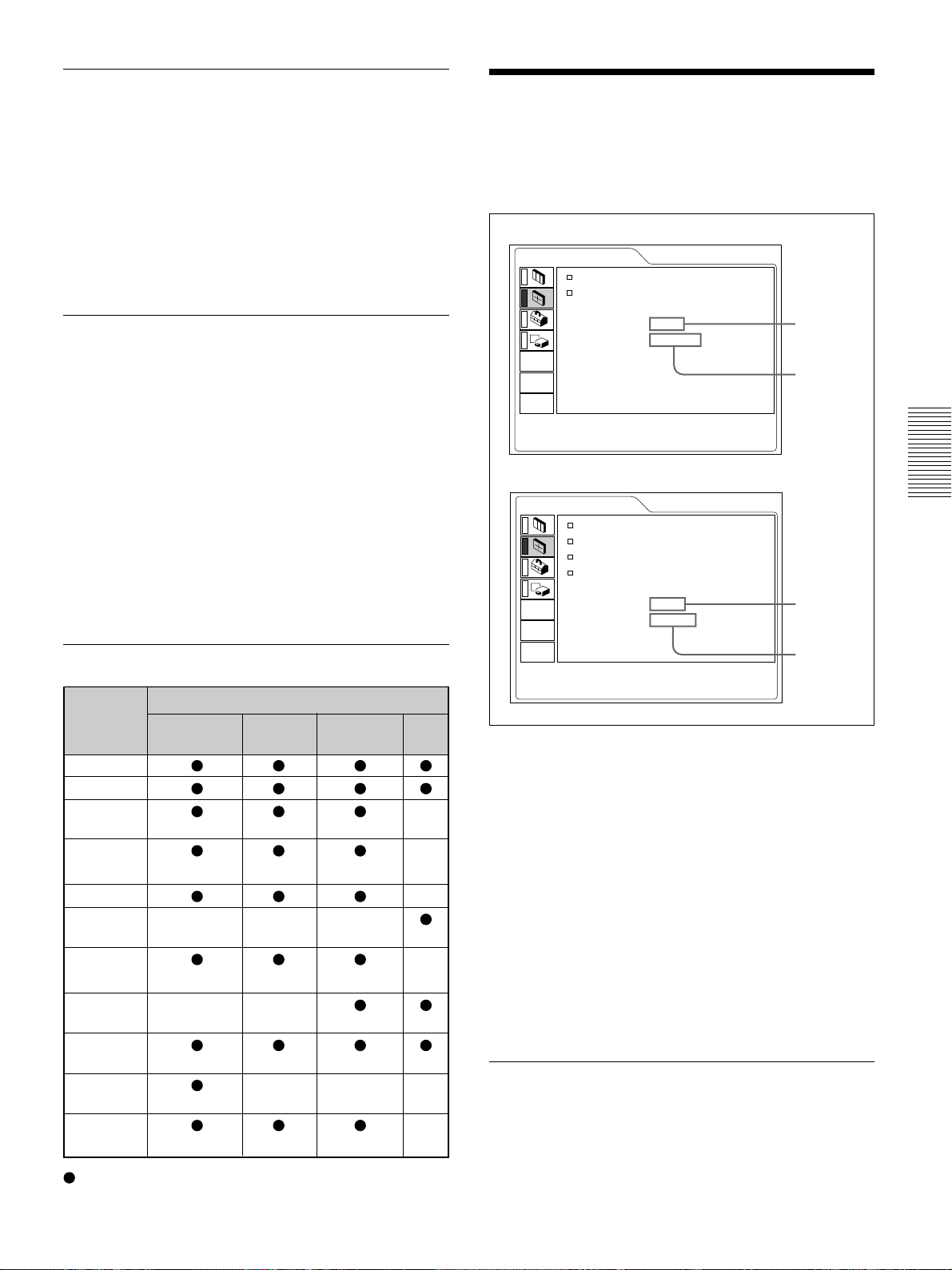
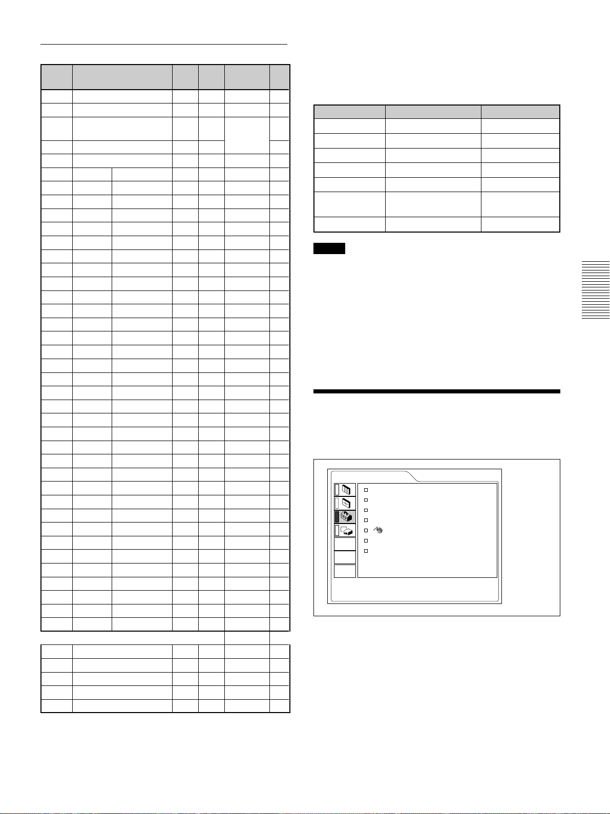
The SET SETTING Menu
The SET SETTING menu is used for changing the
settings of the projector.
SET SETTING
Operation
STATUS: ON
INPUT-B
TERM:PC DIGITAL
INPUT-A: COMPUTER
AUTO INPUT SEL
LANGUAGE
POWER SAVING
IR RECEIVER
: OFF
: ENGLISH
: OFF
: FRONT&REAR
INPUT-A
43
44
45
47
48
480/60P (Progressive component)
575/50P (Progressive component)
1080/50i
720/60p
720/50p
31.470 60.000
31.250 50.000
28.130 50.000
45.000 60.000
37.500 50.000
1. Select an item
Use the M or m key to select the item, then press the
, or ENTER key.
2. Change the setting
Press the M or m key to change the setting.
To restore the original screen, press the ENTER or
<
key.
.........................................................................................................................................................................................................
1) VESA is a registered trademark of Video Electronics Standard Association.
2) PC-98 is a registered trademark of NEC Corporation.
25 (GB)
Page 26
The SET SETTING Menu / The INSTALL SETTING Menu
STATUS (on-screen display)
Sets up the on-screen display.
ON: Shows all of the on-screen displays.
OFF: Turns off the on-screen displays except for the
menus, a message when turning off the power,
and warning messages.
For details on the warning messages, see page 33 (GB).
INPUT-B TERM.
Set to PC ANALOG when the RGB signal input to the
INPUT B RGB (DVI) connector is analog, and to PC
DIGITAL when the input RGB signal is digital.
INPUT-A
Selects the computer, component or video GBR (15k
RGB, DTV, HDTV) signal input from the INPUT A
connector.
Note
If the setting is not correct, “Please check INPUT-A
setting.” appears on the screen and the color of the
picture becomes strange or the picture is not
displayed.
IR RECEIVER
Selects the remote control detectors on the front and
rear of the projector.
FRONT & REAR: Activates both the front and rear
detectors.
FRONT: Activates the front detector only.
REAR: Activates the rear detector only.
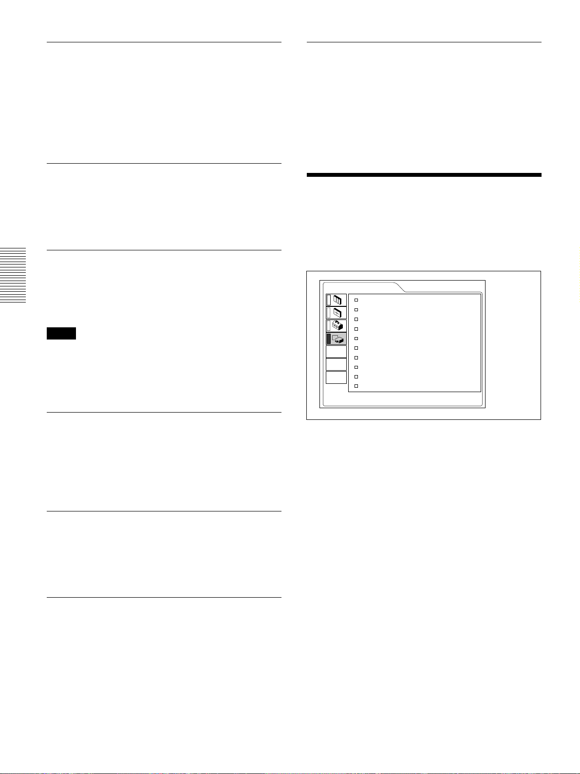
The INSTALL SETTING
Menu
The INSTALL SETTING menu is used for changing
the settings of the projector.
INSTALL SETTING
KEYSTONE MEM:
DIGIT KEYSTONE:
INSTALLATION:
LENS CONTROL:
MENU POSITION:
MENU COLOR:
MENU BACKGRND:
INPUT-C FUNC.:
LAMP MODE: STANDARD
LAMP TIMER: 234h
ON
0
CEILING-FRONT
ON
CENTER
STANDARD
STANDARD
ON
INPUT-A
AUTO INPUT SEL
When set to ON, the projector detects input signals in
the following order: INPUT-A/INPUT-B/INPUT-C/
VIDEO/S-VIDEO. It indicates the input channel when
the power is turned on or the INPUT key is pressed.
LANGUAGE
Selects the language used in the menu and on-screen
displays.
Available languages are: English, French, German,
Italian, Spanish, Japanese and Chinese.
POWER SAVING
When set to ON, the projector goes into the power
saving mode if no signal is input for 10 minutes.
Operation
1. Select an item
Use the M or m key to select the item, then press the
, or ENTER key.
2. Adjust an item
• When changing the adjustment level:
To increase the number, press the M or , key.
To decrease the number, press the m or < key.
Press the ENTER key to restore the original screen.
• When changing the setting:
Press the M or m key to change the setting.
Press the ENTER or < key to restore the original
screen.
26 (GB)
Page 27
The INSTALL SETTING Menu
KEYSTONE MEM
ON: DIGIT KEYSTONE setting is stored.
The data is retrieved when the projector power is
turned on. The setting will remain the same every
time.
OFF: DIGIT KEYSTONE is reset to 0 when the
power is turned on next time.
DIGIT KEYSTONE
Corrects the trapezoid caused by the projection angle.
If the base edge is longer, set a negative value; if the
upper edge is longer, set a positive value to square the
image.
Note
If you adjust SHIFT (page 24) and DIGIT
KEYSTONE for the UXGA input signal, the picture
may not be displayed correctly.
MENU POSITION
Selects the display position of the menu from TOP
LEFT, BOTTOM LEFT, CENTER, TOP RIGHT and
BOTTOM RIGHT.
MENU COLOR
Selects the tone of the menu display from
STANDARD, WARM, COOL, GREEN or GRAY.
MENU BACKGRND
Selects the intensity of the background picture of the
menu display from DARK, STANDARD or LIGHT.
INPUT-C FUNC.
Set to ON when using the Windows CE function.
INSTALLATION
Sets to reverse the picture horizontally or vertically.
FLOOR-FRONT: The picture is not reversed.
CEILING-FRONT: The picture is reversed
horizontally and vertically.
FLOOR-REAR: The picture is reversed
horizontally.
CEILING-REAR: The picture is reversed
vertically.
Note
In case of using a mirror, be careful of installation
since the picture may be reversed.
LENS CONTROL
When set to OFF, the LENS CONTROL FOCUS,
ZOOM and SHIFT keys do not function.
Note
Be sure to exit every application software that is open
before you switch the setting ON to OFF. Otherwise,
system down may occur and you may not restart the
projector.
LAMP MODE
Sets the lamp brightness in the projection.
STANDARD: Illuminates with normal brightness.
LOW: Reduces fan noise and power consumption.
Compared with the STANDARD setting, the
brightness of an image projecting under the LOW
setting will be low.
If the LAMP MODE is set to LOW, the next time the
power is turned on, the lamp will use the
STANDARD setting for the first 3 minutes, and then
go to LOW.
LAMP TIMER
Indicates how long the lamp has been turned on.
Note
This only displays the time. You cannot alter the
display.
27 (GB)
Page 28
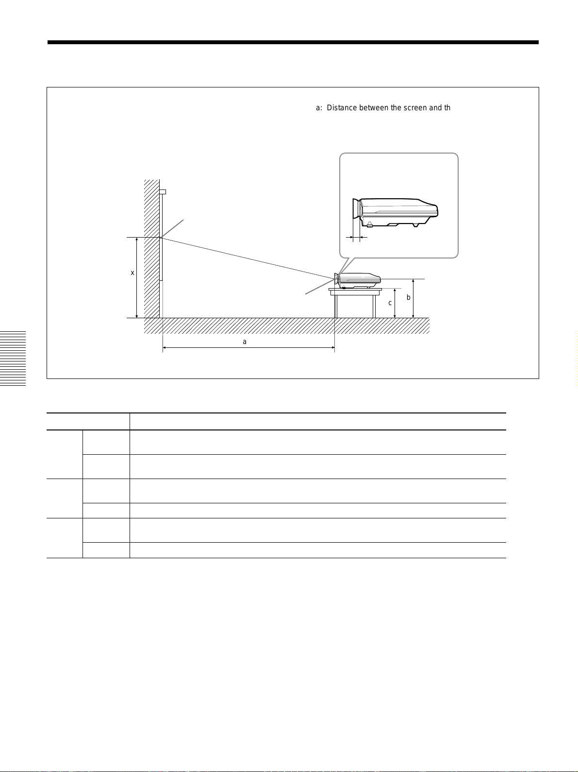
Installation Example
Installation Example
a: Distance between the screen and the center of the lens
b: Distance from the floor to the center of the lens
c: Distance from the floor to the foot of the projector
x: Free
Wall
Center of the screen
x
Center of the lens
a
Screen size (inches) 40 60 80 100 120 150 180 200 250 300
Minimum
a
Maximum
Minimum
b
Maximum x
Minimum
c
Maximum x–100 (x–4)
1490 2280 3060 3850 4630 5810 6980 7770 9730 11690
(58 3/4) (89 7/8) (120 1/2) (151 5/8) (182 3/8) (228 7/8) (274 7/8) (306) (383 1/8) (460 3/8)
1820 2780 3740 4700 5660 7100 8540 9500 11900 14300
(71 3/4) (109 1/2) (147 3/8) (185 1/8) (222 7/8) (279 5/8) (336 3/8) (374 1/8) (468 5/8) (563 1/8)
x–305 x–457 x–610 x–762 x–914 x–1143 x–1372 x–1524 x–1905 x–2286
(x–12 1/8) (x–18) (x–24 1/8) (x–30) (x–36) (x–45) (x–54 1/8) (x–60) (x–75 1/8) (x–90 1/8)
x–415 x–567 x–720 x–872 x–1024 x–1253 x–1482 x–1634 x–2015 x–2396
(x–16 3/8) (x–22 3/8) (x–28 3/8) (x–34 3/8) (x–40 3/8) (x–49 3/8) (x–58 3/8) (x–64 3/8) (x–79 11/32) (x–94 3/8)
Distance between the
front of the cabinet and
the center of the lens
Standard lens:
30.5 mm (1 1/4 inches)
b
c
Floor
Unit: mm (inches)
To calculate the installation measurement (unit: mm)
SS: screen size diagonal (inches)
a (minimum) = {(SS × 50.127/1.3102) – 73.9} × 1.025
a (maximum) = {(SS × 64.519/1.3102) – 107.9} × 0.975
b (minimum) = x – (SS/1.3102 × 9.984)
c (minimum) = x – (SS/1.3102 × 9.984 + 110)
28 (GB)
Page 29
Notes for Installation
Notes for Installation
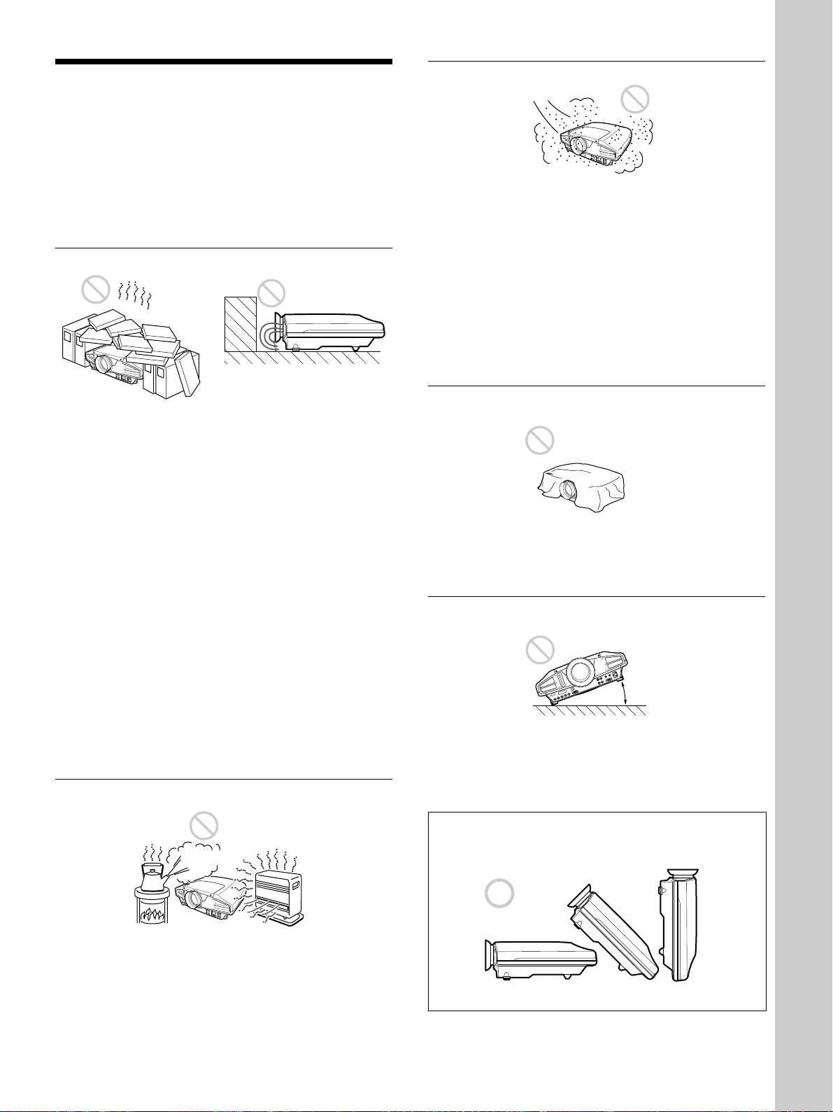
Unsuitable Installation
Do not install the projector in the following situations.
These installations may cause malfunction or damage
to the projector.
Poorly ventilated
•Allow adequate air circulation to prevent internal
heat build-up. Do not place the unit on surfaces
(rugs, blankets, etc.) or near materials (curtains,
draperies) that may block the ventilation holes.
When the internal heat builds up due to the block-up,
the temperature sensor will function with the
message “High temp.! Lamp off in 1 min.” The
power will be turned off automatically after one
minute.
•Leave space of more than 50 cm (19
around the unit.
•Be careful that the ventilation holes may inhale
tininess such as a piece of paper.
•If you put something in front of the front ventilation
holes, the exhaust may be inhaled into the projector
through the ventilation holes at the bottom, causing
the internal temperature to rise, which activates the
protection circuit. Install the projector so that the
exhaust is not blocked.
Highly heated and humid
3
/4 inches)
Very dusty
Avoid installing the unit in a location where there is a
lot of dust; otherwise, the air filter will be obstructed.
The dust blocking the air through the filter may cause
raising the internal heat of the projector. Clean it up
periodically.
Unsuitable Conditions for Use
Do not do any of the following.
Blocking the ventilation holes
Avoid using something to cover over the ventilation
holes; otherwise, the internal heat may build up.
Tilting right/left
20°
Avoid using as the unit tilts more than 20 degrees. Do
not install the unit other than on the floor or ceiling.
These installations may cause malfunction.
Installation
•Avoid installing the unit in a location where the
temperature or humidity is very high, or temperature
is very low.
•To avoid moisture condensation, do not install the
unit in a location where the temperature may rise
rapidly.
The front to back tilt angle of this projector is not
limited.
29 (GB)
Page 30
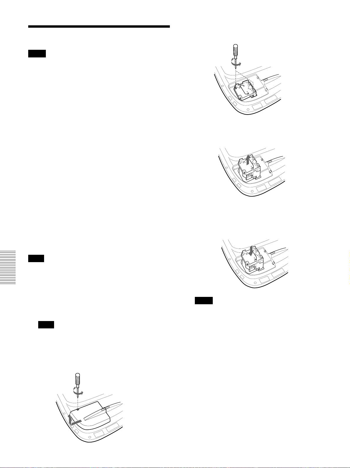
Maintenance
Maintenance
Notes
•If the lamp breaks, consult with qualified Sony
personnel.
•Pull out the lamp unit by holding the handle. If you
touch the lamp unit, you may be burned or injured.
•When removing the lamp unit, make sure it remains
horizontal, then pull straight up. Do not tilt the lamp
unit. If you pull out the lamp unit while tilted and if
the lamp breaks, the pieces may scatter, causing
injury.
Replacing the Lamp
When the lamp has burnt out or dims, or “Please
replace the lamp” appears on the screen, replace the
lamp with a new one. The message appears after 1000
hours for the STANDARD setting, or about 1500
hours for the LOW setting in the LAMP MODE.
Use LMP-F250 Projector Lamp as the replacement
lamp.
The lamp life varies depending on conditions of use.
When replacing the lamp after using the
projector
Turn off the projector, then unplug the power cord.
Wait for at least an hour for the lamp to cool.
3 Loosen two screws on the lamp unit with the
Phillips screwdriver.
4 While holding the handle and keeping the lamp
unit horizontal, pull straight up.
5 Insert the new lamp all the way in until it is
securely in place. Tighten the two screws. Fold
down the handle.
Note
The lamp becomes a high temperature after turning
off the projector with the I / 1 key. If you touch the
lamp, you may scald your finger. When you replace
the lamp, wait for at least an hour for the lamp to cool.
1 Place a protective sheet (cloth) beneath the
projector and put the projector face down.
Note
When replacing the lamp, be sure it is on a flat
and stable surface.
2 Slide to open the lamp cover by loosening one
screw with the Phillips screwdriver.
Notes
•Be careful not to touch the glass surface of the
lamp.
•The power will not turn on if the lamp is not
secured properly.
6 Close the lamp cover and tighten the screw.
7 Turn the projector back over.
8 Connect the power cord and turn the projector to
the standby mode.
9 Press the following keys on the control panel in
the following order for less than in five seconds
each: RESET, <, ,, ENTER.
30 (GB)
Page 31

Maintenance
Notes
•Be sure to use the LMP-F250 Projector Lamp for
replacement. If you use lamps other than LMP-F250,
the projector may cause a malfunction.
•Be sure to turn off the projector and unplug the
power cord before replacing the lamp.
•Do not put your hands into the lamp replacement
spot, or not fall any liquid or object into it to avoid
electrical shock or fire.
Disposal of used projector lamp
As the materials used in this lamp are similar to those
of a fluorescent lamp, you should dispose of a used
projector lamp in the same way as a fluorescent lamp.
Cleaning the Air Filter
The air filter should be cleaned every 300 hours.
When it becomes difficult to remove the dust from the
filter, replace the filter with a new one.
To clean the air filter, follow the steps below:
1 Turn off the power and unplug the power cord.
2 Raise the side of the projector, and pull out the air
filter.
3 Remove the dust from the filter with a vacuum
cleaner.
Maintenance
4 Insert the air filter all the way in utnil it is securely
in place.
Notes
•If you neglect the air filter, dust may accumulate,
clogging it. As a result, the temperature may rise
inside the unit, leading to a possible malfunction or
fire.
•Be sure to insert the air filter firmly; the power will
not be turned on if it is not closed securely.
31 (GB)
Page 32

Troubleshooting
Troubleshooting
If the projector appears to be operating erratically, try to diagnose and correct the problem, using the following
guide. If the problem still persists, consult with qualified Sony personnel.
Power
Symptom
The power is not turned on.
Image
Symptom
No picture.
The picture is noisy.
On-screen display does not
appear.
The picture from INPUT B
connector is not projected.
The digital picture from INPUT
B connector is not projected.
The picture from INPUT C is
frozen.
Color balance of the video
picture is not correct.
Cause
The power has been turned off and on
with the I / 1 key at a short interval.
The lamp cover is detached.
The air filter is not inserted securely. Insert the air filter securely
Cause
Cable is disconnected or not connected
properly.
Input selection is incorrect. Select the input source correctly using the INPUT
The picture is cut off. Press the PIC MUTING key to release the muting
The computer signal is not set to output
to external monitor.
The computer signal is set to output to
both the LCD of the computer and
external monitor.
Noise may appear on the background
depending on the combination of the
numbers of dot input from the connector
and numbers of pixel on the LCD panel.
STATUS in the SET SETTING menu has
been set to OFF.
Setting for INPUT-B TERM. in the SET
SETTING menu is incorrect.
The connecting procedures are wrong. Make connections using the proper procedures
There is something wrong with the
network.
The color system of the input signal is
not set correctly.
Remedy
Wait for about 120 seconds before turning on the
(see page 20 (GB))
power
Close the lamp cover securely
Remedy
Check that the proper connections have been
(see pages 15 (GB) to 17 (GB))
made
(see page 18 (GB))
key
function
Set the computer signal to output to external
monitor
Set the computer signal to output only to external
monitor
Change the desktop pattern on the connected
computer.
Set STATUS in the SET SETTING menu to ON
(see page 26 (GB))
Set INPUT-B TERM. in the SET SETTING menu
correctly according to the input signal
26 (GB)).
(see page 15 (GB))
Set INPUT C FUNC. in the INSTALL SETTING
menu to OFF, then set it to ON again
(GB)).
Set COLOR SYS in the PICTURE CTRL menu to
match the color system of the input signal
page 23 (GB)).
(see page 19 (GB))
(see page 15 (GB))
(see page 15 (GB))
.
(see page 30 (GB))
(see page 31 (GB)).
.
.
.
.
.
.
(see page
.
(see page 27
(see
.
32 (GB)
Page 33

Others
Troubleshooting
Symptom
The LAMP/COVER indicator
flashes.
The LAMP/COVER indicator
lights up.
The TEMP/FAN indicator
flashes.
The TEMP/FAN indicator
lights up.
Both LAMP/COVER and
TEMP/FAN indicators light up.
The INPUT C window does
not appear, or INPUT C
cannot be selected.
The menu display does not
appear even when you press
the MENU key on the Remote
Commander.
Cause
The lamp cover is detached or the air
filter is not inserted securely.
The lamp has reached the end of its life.
The lamp becomes a high temperature. Wait for 120 seconds to cool down the lamp and
The fan is broken.
The internal temperature is unusually
high.
The electric system failed.
INPUT C FUNC. is set to OFF.
The PJ/NETWORK select switch on the
Remote Commander is set to
NETWORK.
Remedy
Attach the lamp cover or insert the air filter
securely
Replace the lamp
turn on the power again
Consult with qualified Sony personnel.
Check to see if nothing is blocking the ventilation
holes.
Consult with qualified Sony personnel.
Set INPUT C FUNC. in the INSTALL SETTING
menu to ON
Set the PJ/NETWORK select switch to PJ, then
press the MENU key.
(see pages 30 (GB) and 31 (GB))
Warning messages
Use the list below to check the meaning of the messages displayed on the screen.
Message
Meaning Remedy
(see page 30 (GB)).
(see page 20 (GB))
(see page 27 (GB))
.
.
.
High temp.!
Lamp off in 1 min.
Frequency is out of range! This input signal cannot be projected as
Please check INPUT-A
setting.
Please replace the LAMP. It is time to replace the lamp.
Backup Battery Very Low A backup battery for the network is
Internal temperature is too high. Turn off the power.
the frequency is out of the acceptable
range of the projector.
The resolution setting of the output
signal of a computer is too high.
You have input RGB signal from the
computer when INPUT-A in the SET
SETTING menu is set to COMPONENT
or VIDEO GBR.
exhausted.
Check to see if nothing is blocking the ventilation
holes.
Input a signal that is within the range of the
frequency.
Set the setting of output to the XGA
(GB)).
Set INPUT-A correctly
Please replace the lamp.
Consult with qualified Sony personnel.
Caution messages
Use the list below to check the meaning of the messages displayed on the screen.
Message
NO INPUT
Not applicable!
LENS CONTROL is locked!
Do you wish to unlock?
Meaning Remedy
No input signal Check connections
You have pressed the wrong key. Press the appropriate key.
LENS CONTROL in the INSTALL
SETTING menu is set to OFF.
Select YES, or set LENS CONTROL in the
INSTALL SETTING menu to ON, according to
your requirement.
(see page 15
(see page 26 (GB))
.
(see pages 15 (GB) to 17 (GB))
.
33 (GB)
Page 34

Specifications
Specifications
Optical characteristics
Projection system 3 LCD panels, 1 lens, projection
system
LCD panel 1.3-inch TFT SONY LCD panel
with micro-lens array,
2,359,296 pixels
(1024 × 768 pixels × 3)
Lens Approx. 1.3 times power zoom/
focus lens
f 50.8 to 64.0 mm/F 1.7 to 2.0
Lamp 250 W UHP
Projection picture size
Range: 40 to 300 inches (diagonal
measure)
Light output ANSI lumen
Throwing distance 40-inch: 1490 to 1820 mm
60-inch: 2280 to 2780 mm
80-inch: 3060 to 3740 mm
100-inch: 3850 to 4700 mm
120-inch: 4630 to 5660 mm
150-inch: 5810 to 7100 mm
180-inch: 6990 to 8540 mm
200-inch: 7770 to 9500 mm
250-inch: 9740 to 11900 mm
300-inch: 11700 to 14300 mm
Electrical characteristics
Color system NTSC3.58/PAL/SECAM/NTSC4.43/
PAL-M/PAL-N system,
switched automatically/manually
Resolution 750 horizontal TV lines (Video
input)
1024 × 768 pixels (RGB input)
Acceptable computer signals
fH: 15 to 91 kHz
fV: 43 to 85 Hz
1)
3500 lm
3
/4 to 71 3/4 inches)
(58
7
/8 to 109 1/2 inches)
(89
1
/2 to 147 3/8 inches)
(120
5
/8 to 185 1/8 inches)
(151
3
/8 to 222 7/8 inches)
(182
7
/8 to 279 5/8 inches)
(228
1
/4 to 336 3/8 inches)
(275
(306 to 374
5
(383
3
(460
1
/8 to 468 5/8 inches)
/4 to 563 1/8 inches)
/8 inches)
Input/Output
VIDEO IN VIDEO: BNC type
Composite video: 1 Vp-p ±2 dB
sync negative (75 ohms
terminated)
S VIDEO: Y/C mini DIN 4-pin
type (male)
Y (luminance): 1 Vp-p ±2 dB
sync negative (75 ohms
terminated)
C (chrominance): burst
0.286 Vp-p ±2 dB (NTSC)
(75 ohms terminated),
burst 0.3 Vp-p ±2 dB (PAL)
(75 ohms terminated)
VIDEO OUT VIDEO: Loop-through BNC type
Loop-through output from the
VIDEO IN connector
S VIDEO: Loop-through mini DIN
4-pin type (male)
Loop-through output from the S
VIDEO IN connector
INPUT A Analog RGB/component: 5BNC
(female)
R/R-Y: 0.7 Vp-p ±2 dB (75
ohms terminated)
G: 0.7 Vp-p ±2 dB (75 ohms
terminated)
G with sync/Y: 1 Vp-p ±2 dB
sync negative (75 ohms
terminated)
B/B-Y: 0.7 Vp-p ±2 dB (75
ohms terminated)
SYNC/HD:
Composite sync input: 1-5 Vp-p
high impedance, positive/
negative
Horizontal sync input: 1-5 Vp-p
high impedance, positive/
negative
VD:
Vertical sync input: 1-5 Vp-p
high impedance, positive/
negative
INPUT B Digital/Analog RGB: DVI-I
(TMDS)
INPUT C ETHER
10BASE-T/100BASE-TX
standard
PC CARD slot
PC card slot Type II
.........................................................................................................................................................................................................
1) ANSI lumen is a measuring method of American National Standard IT 7.228.
34 (GB)
Page 35

Specifications
MONITOR OUT HD D-sub 15-pin (female)
R/R-Y, G/Y, B/B-Y: Gain Unity,
75ohms
SYNC/HD, VD: 4Vp-p (open),
1Vp-p (75ohms)
RS-232C D-sub 9-pin (female)
CONTROL S IN/PLUG IN POWER
Stereo minijack 5Vp-p, plug in
power, DC5V
TRIG Minijack
Power on: DC 12 V, output
impedance: 4.7 kilohms
Power off: 0 V
Safety regulations UL, cUL
DHHS
DNHW
FCC Class A
IC Class A
NEMKO
CE (LVD, EMC)
C-Tick
Laser beam
Laser type Class 2
Wavelength 645 nm
Output 1 mW
Supplied accessories
Remote Commander RM-PJM50 (1)
Size AA (R6) batteries (2)
Lens Cap (1)
AC power cord (1)
Operating Instructions (1)
Operating Instructions for
Networking (1)
Installation Manual for Dealers (1)
Warranty Booklet (1)
Design and specifications are subject to change
without notice.
Optional accessories
Projector Lamp LMP-F250 (for replacement)
Projector Suspension Support PSS-620
Monitor Cable
SMF-400 (HD D-sub 15-pin (male) y 5 × BNC
(male))
Signal Interface Cable
SIC-10 (5 × BNC (male) y 5 × BNC (male))
Projection Lens
Long Focus Zoom Lens VPLL-ZM101
Short Focus Zoom Lens VPLL-ZM31
Fixed Short Focus Lens VPLL-FM21
Other
General
Dimensions 480 × 167 × 502 mm (19 × 6 1/2 ×
Mass Approx. 10.5 kg (23 lb 2 oz)
Power requirements
Power consumption
Heat dissipation 1228.6 BTU
Operating temperature
Operating humidity
Storage temperature
Storage humidity 10% to 90%
7
19
/8 inches) (w/h/d)
AC 100 to 240 V, 50/60 Hz
Max. 360 W
Standby mode: 5 W (when
INPUT-C FUNC. is set to ON:
10 W)
3.6–1.5A
0°C to 40°C (32°F to 104°F)
35% to 85% (no condensation)
–20°C to 60°C (–4°F to 140°F)
Some of the items may not be available in some areas. For
details, please consult your nearest Sony office.
35 (GB)
Page 36

Specifications
Pin assignment
MONITOR OUT connector (HD D-sub 15-pin,
female)
1R 9NC
2 G 10 GND
3 B 11 GND
4NC 12NC
5 GND 13 HD/C.Sync
6 GND (R) 14 VD
7 GND (G) 15 NC
8 GND (B)
RS-232C connector (D-sub 9-pin, female)
DVI input connector (DVI-I, female)
1 T.M.D.S. Data2– 16 Hot Plug Detect
2 T.M.D.S. Data2+ 17 T.M.D.S. Data0–
3 T.M.D.S. Data2/4 Shield 18 T.M.D.S. Data0+
4 T.M.D.S. Data4– 19 T.M.D.S. Data0/5 Shield
5 T.M.D.S. Data4+ 20 T.M.D.S. Data5–
6 DDC Clock 21 T.M.D.S. Data5+
7 DDC Data 22 T.M.D.S. Clock Shield
8 Analog Vertical Sync 23 T.M.D.S. Clock+
9 T.M.D.S. Data1– 24 T.M.D.S. Clock–
10 T.M.D.S. Data1+ C1 Analog Red
11 T.M.D.S. Data1/3 Shield C2 Analog Green
12 T.M.D.S. Data3– C3 Analog Blue
13 T.M.D.S. Data3+ C4 Analog Horizontal Sync
14 +5V Power C5
Ground
15
(return for +5V, HSync,
and VSync)
Analog Ground
(analog R, G & B return)
1 DCD 6 DSR
2 RX DA 7 RTS
3 TX DA 8 CTS
4 DTR 9 RI
5 GND
36 (GB)
Page 37

Index
Index
A
Adjuster 10 (GB)
Adjusting
memory of the settings 21 (GB)
the picture 22 (GB)
the picture size/shift 24 (GB)
Air filter 31 (GB)
APA function 19 (GB)
ASPECT 24 (GB)
AUTO INPUT SEL 26 (GB)
B
5BNC input connectors 12 (GB), 15 (GB)
Battery
installation 14 (GB)
notes 14 (GB)
BRIGHT 22 (GB)
C
COLOR 22 (GB)
COLOR SYS (System) 23 (GB)
COLOR TEMP 22 (GB)
Condensation 29 (GB)
Connections
component equipment 16 (GB)
computer 15 (GB)
LAN 16 (GB)
VCR 15 (GB)
CONTRAST 22 (GB)
Cut off
the picture 19 (GB)
D, E, F
DDE (Digital Detail Enhancer) 23 (GB)
DIGIT KEYSTONE 27 (GB)
D. (Dynamic) PICTURE 22 (GB)
DOT PHASE 23 (GB)
DVI connector 15 (GB)
pin assignment 36 (GB)
Freeze function 20 (GB)
I, J, K
INPUT-A 26 (GB)
INPUT-B TERM. 26 (GB)
INPUT-C FUNC. 27 (GB)
INPUT SETTING menu 23 (GB)
INSTALL SETTING menu 26 (GB)
INSTALLATION 27 (GB)
Installation example 28 (GB)
IR RECEIVER 26 (GB)
KEYSTONE MEM 27 (GB)
L
LAMP MODE 27 (GB)
Lamp replacement 30 (GB)
LAMP TIMER 27 (GB)
LANGUAGE 26 (GB)
LENS CONTROL 27 (GB)
LENS FOCUS 10, 19 (GB)
LENS SHIFT 10, 19 (GB)
LENS ZOOM 10, 19 (GB)
Location and function of controls
connector panel 12 (GB)
control panel 10 (GB)
front 9 (GB)
rear/bottom 9 (GB)
Remote Commander 13 (GB)
M, N
Menu
clearing the menu display 21 (GB)
INPUT SETTING menu 23 (GB)
INSTALL SETTING menu 26 (GB)
PICTURE CTRL menu 22 (GB)
SET SETTING menu 25 (GB)
using the menu 21 (GB)
MENU BACKGRND 27 (GB)
MENU COLOR 27 (GB)
MENU POSITION 27 (GB)
Messages
cautions 33 (GB)
warnings 33 (GB)
Notes for installation 29 (GB)
unsuitable conditions for use 29 (GB)
unsuitable installation 29 (GB)
R
Remote Commander
battery installation 14 (GB)
D ZOOM key 20 (GB)
FUNCTION key 13 (GB)
laser pointer function 20 (GB)
location and function of controls
13 (GB)
Remote control detector
front 9 (GB)
rear 9 (GB)
setting 26 (GB)
Reset
resettable items 21 (GB)
resetting the item 21 (GB)
RGB ENHANCER 22 (GB)
RS-232C connector 12 (GB)
pin assingment 36 (GB)
S
SCAN CONV (Scan converter) 24 (GB)
Screen size 14 (GB), 34 (GB)
SET SETTING menu 25 (GB)
SHARP 22 (GB)
SHIFT 24 (GB)
SIZE H 24 (GB)
Specifications 34 (GB)
STATUS (on-screen display) 26 (GB)
Supplied accessories 35 (GB)
T, U
Troubleshooting 32 (GB)
V, W, X, Y, Z
Ventilation holes
exhaust 9 (GB)
intake 9 (GB)
G
GAMMA MODE 22 (GB)
H
HUE 22 (GB)
O
Optional accessories 35 (GB)
P, Q
PICTURE CTRL menu 22 (GB)
Pin assignment 36 (GB)
Power
turn off 20 (GB)
turn on 18 (GB)
POWER SAVING 11 (GB), 26 (GB)
Precautions 7 (GB)
Projecting 18 (GB)
37 (GB)
Page 38

AVERTISSEMENT
Pour éviter tout risque d’incendie ou
d’électrocution, ne pas exposer cet appareil à
la pluie ou à l’humidité.
Pour prévenir tout risque d’électrocution, ne
pas ouvrir le boîtier. Confier l’entretien de cet
appareil exclusivement à un personnel
qualifié.
Pour les utilisateurs au Canada
Cet appareil numérique de la classe A est conforme à la
norme NMB-003 du Canada.
La prise doit être près de l’appareil et facile d’accès.
LASER RADIATION
DO NOT STARE INTO BEAM
CLASS 2 LASER PRODUCT
RAYONNEMENT LASER
NE PAS REGARDER DANS LE FAISCEAU
APPAREIL A LASER DE CLASSE 2
LASER–STRAHLING
NIGHT IN DEN STRAHL BLICKEN
LASER KLASSE 2
MAX OUTPUT:1mW
WAVE LENGTH:645nm
Cette étiquette est
apposée au dos de la
télécommande.
Cette étiquette est
apposée sur le côté de la
télécommande.
CAUTION
LASER RADIATION
DO NOT STARE INTO BEAM
WAVE LENGTH:645nm
MAX OUTPUT:1mW
CLASS II LASER PRODUCT
COMPLIES WITH DHHS 21 CFR
SUBCHAPTER J
SONY CORPORATION
6-7-35 KITASHINAGAWA
SHINAGAWA-KU,TOKYO,JAPAN
A
MANUFACTURED;
AVOID EXPOSURE
RADIATION IS EMITTED
FROM THIS APERTURE.
-
LASER
Le rayon laser est émis par cette fenêtre.
Attention
L’utilisation de commandes ou de réglages, ou l’exécution
de procédures autres que celles spécifiées peut entraîner
une exposition dangereuse à des radiations.
Remarques
• N’orientez pas le laser en direction de personnes et ne
regardez pas dans l’émetteur laser.
• En cas de problème avec la télécommande, adressezvous à un personnel Sony qualifié. Nous remplaçons la
télécommande par une neuve conformément aux termes
de la garantie.
Cette étiquette est apposée
au dos de la télécommande.
Cette étiquette est apposée
au dos de la télécommande.
Avertissement sur la connexion électrique
Utilisez un cordon d’alimentation approprié à votre tension secteur locale.
Etats-Unis, Europe Royaume-Uni, Irlande, Japon
Canada continentale Australie, Nouvelle-Zélande
Type de fiche VM0233 290B YP-12A COX-07 —
1)
YP332
Extrémité femelle VM0089 386A YC-13B COX-02 VM0310B YC-13
Type de cordon SJT SJT H05VV-F H05VV-F N13237/CO-228 VCTF
Tension et courant nominaux
10A/125V 10A/125V 10A/250V 10A/250V 10A/250V 7A/125V
Agréation de sécurité UL/CSA UL/CSA VDE VDE VDE DENTORI
.........................................................................................................................................................................................................
1) Utilisez la fiche correcte pour votre pays.
2 (FR)
Page 39

Table des matières
Présentation
Installation et projection
Précautions ................................................................ 5 (FR)
Caractéristiques ........................................................ 6 (FR)
Emplacement et fonction des commandes............. 7 (FR)
Avant......................................................................... 7 (FR)
Arrière/Dessous ........................................................ 7 (FR)
Panneau de commande.............................................. 8 (FR)
Panneau des connecteurs ........................................ 10 (FR)
Télécommande........................................................ 11 (FR)
Installation du projecteur........................................ 12 (FR)
Raccordement.......................................................... 13 (FR)
Raccordement à un ordinateur ou un
magnétoscope .................................................... 13 (FR)
Raccordement à un système à signal RVB
15k/à des composants ........................................ 14 (FR)
FR
Français
Raccordement au LAN ........................................... 14 (FR)
Sélection de la langue d’affichage des menus ..... 16 (FR)
Projection ................................................................. 16 (FR)
Ajustements et réglages à l’aide du menu
Utilisation du MENU ................................................19 (FR)
Le menu CTRL IMAGE ............................................ 19 (FR)
Le menu REGL ENTREE .........................................21 (FR)
Le menu REGLAGE ................................................. 23 (FR)
Le menu REGL. INSTAL..........................................24 (FR)
Installation
Exemples d’installation........................................... 26 (FR)
Remarques concernant l’installation..................... 27 (FR)
Installation déconseillée.......................................... 27 (FR)
Conditions d’utilisation déconseillées .................... 27 (FR)
3 (FR)
Page 40

Entretien
Divers
Entretien ...................................................................28 (FR)
Remplacement de la lampe ..................................... 28 (FR)
Nettoyage du filtre à air .......................................... 29 (FR)
Dépannage ............................................................... 30 (FR)
Spécifications .......................................................... 32 (FR)
Index ......................................................................... 35 (FR)
4 (FR)
Page 41

Précautions
Précautions
Sécurité
•Vérifiez si la tension de service de votre appareil est
identique à la tension secteur locale.
•Si des liquides ou des solides pénètrent dans le
châssis, débranchez l’appareil et faites-le vérifier par
un personnel qualifié avant de le remettre en service.
•Débranchez l’appareil de la prise murale si vous
prévoyez de ne pas l’utiliser pendant plusieurs jours.
•Pour débrancher le câble, saisissez-le par la fiche. Ne
tirez jamais sur le câble proprement dit.
•La prise d’alimentation doit se trouver à proximité de
l’appareil et être aisément accessible.
•L’appareil n’est pas déconnecté de la source
d’alimentation (secteur) aussi longtemps qu’il reste
branché sur la prise murale, même si l’appareil
proprement dit a été mis hors tension.
•Ne regardez pas vers l’objectif lorsque la lampe est
allumée.
•N’orientez pas le laser vers des personnes et ne
regardez pas vers le transmetteur laser.
•Ne placez pas la main ou d’autres objets à proximité
des orifices de ventilation — l’air expulsé est
brûlant.
•Veillez à ne pas vous coincer les doigts dans le
support réglable lorsque vous soulevez le projecteur.
Ne poussez pas trop fort sur le dessus du projecteur
lorsque le support réglable est abaissé.
•Veillez à tenir le projecteur fermement avec vos
deux mains lorsque vous le transportez.
Prévention de la surchauffe interne
Après avoir mis l’appareil hors tension au moyen de
1
la touche I /
commande, ne débranchez pas l’appareil de la prise
secteur tant que le ventilateur de refroidissement
continue à tourner.
Attention
Le projecteur est équipé d’orifices de ventilation
(prise d’air) sur le dessous et d’orifices de ventilation
(sortie d’air) à l’avant. N’obstruez pas ces orifices et
ne placez rien à proximité, car vous risqueriez de
provoquer une surchauffe interne pouvant entraîner
une altération de l’image ou une détérioration du
projecteur.
de la télécommande ou du panneau de
Entretien
•Pour que le châssis concerve son aspect neuf,
nettoyez-le régulièrement à l’aide d’un chiffon doux.
Les taches tenaces s’éliminent en frottant avec un
chiffon doux légèrement imprégné d’une solution
détergente neutre. N’utilisez en aucun cas des
solvants puissants tels que du diluant ou de la
benzine ni de nettoyants abrasifs qui risqueraient
d’altérer le fini du châssis.
•Ne touchez pas l’objectif. Pour éliminer la poussière
de l’objectif, utilisez un chiffon doux et sec.
N’utilisez pas de chiffon humide, de solution
détergente ni de diluant.
•Nettoyez le filtre à air à intervalles réguliers (toutes
les 300 heures).
Présentation
Eclairage
•Pour obtenir la meilleure qualité d’image possible,
l’avant de l’écran ne doit pas être directement exposé
à la source d’éclairage ni au rayonnement solaire.
•Nous préconisons un éclairage au moyen de spots
fixés au plafond. Placez un écran sur les lampes
fluorescentes de façon à éviter une altération du
niveau de contraste.
•Occultez les fenêtres qui font face à l’écran au
moyen de draperies opaques.
•Il est préférable d’installer le projecteur dans une
pièce où le sol et les murs ne sont pas revêtus d’un
matériau réfléchissant la lumière. Si le sol et les murs
réfléchissent la lumière, nous vous conseillons de
remplacer le revêtement du sol et des murs par une
couleur sombre.
Remballage
Conservez le carton d’emballage et les matériaux de
conditionnement d’origine, car ils constituent une
protection idéale pour le transport de l’appareil. Pour
une protection maximale, remballez votre appareil
comme il a été emballé à l’origine en usine.
Sur le projecteur LCD
Le projecteur LCD est fabriqué avec une technologie
de haute précision. Il se peut cependant que de petits
points noirs et/ou des points lumineux (rouge, bleu ou
vert) apparaissent continuellement sur le projecteur
LCD. Il s’agit d’un résultat normal du processus de
fabrication et ne constitue aucunement un
dysfonctionnement.
5 (FR)
Page 42

Caractéristiques
Caractéristiques
Luminosité élevée, haute qualité d’image
•Luminosité élevée
Le panneau LCD à taux d’ouverture élevé, doté d’une
micro lentille, et la lampe 250 W UHP fournissent une
luminosité élevée (flux lumineux 3500 lumens ANSI)
ainsi qu’une excellente uniformité de l’image.
•Haute résolution
Grâce a trois panneaux de 1,3 pouce et d’environ
790.000 pixels XGA, ce projecteur est capable de
projeter une image claire avec des résolutions de 1024
× 768 pixels en entrée RVB et de 750 lignes TV
horizontales en entrée vidéo.
•Haute qualité d’image
La technologie DDE (Dynamic Detail Enhancer),
récemment développée par Sony en exclusivité,
permet de convertir un signal vidéo du format
entrelacé en format progressif, vous permettant ainsi
d’obtenir une image plus précise. Cette technique
reproduit également les films en format 2-3
intermittent sans à-coups entre les images.
L’optimiseur interne RVB donne des images RVB
plus nettes et la correction Gamma numérique 3D à 10
bits assure une bonne uniformité des images.
Installation pratique et simplifiée
•Fonction du zoom électrique/mise au point et
réglage vertical
Le projecteur est équipé d’un zoom 1,3 × et d’un
objectif électriques qui vous permettent de modifier la
taille de l’image projetée sans avoir à déplacer le
projecteur. La fonction de réglage vertical de
l’objectif vous donne une plus grande souplesse pour
choisir l’emplacement du projecteur sans vous soucier
de la déformation trapézoïdale. De même, trois
objectifs optionnels sont disponibles pour le
projecteur, selon vos conditions d’installation.
•Objectif en position centrale
Le projecteur est conçu pour placer l’objectif au
centre de l’appareil. Cela permet une installation
facile étant donné que le centre de l’objectif s’aligne
sur le centre de l’écran.
•Installation inclinée (vers l’avant et vers l’arrière)
Vous pouvez installer le projecteur en l’inclinant à 90°
vers l’arrière ou à 90° vers l’avant. Vous pouvez
utiliser un miroir pour la rétro projection.
•Installation de deux projecteurs
Grâce à la fonction de réglage vertical de l’objectif,
deux projecteurs peuvent être mis l’un au-dessus de
l’autre, ce qui améliore la luminosité de l’image.
Compatibilité multi-scan
•Connecteurs DVI et 5BNC
Ce projecteur possède un connecteur DVI (Digital
Visual Interface), le plus récent des connecteurs
d’entrée numériques, ce qui permet de le raccorder à
des appareils RVB numériques ou analogiques
équipés d’une sortie DVI. Les connecteurs d’entrée
5BNC vous permettent de raccorder le projecteur à
une station de travail émettant des signaux haute
résolution et de raccorder le projecteur à un ordinateur
distant.
Le projecteur dispose de 44 données prédéfinies dans
la mémoire pour les signaux d’entrée, ce qui vous
permet de projeter une image claire sur l’écran
simplement en raccordant l’équipement et en
appuyant sur la touche APA (Auto Pixel Alignment).
•Divers signaux d’entrée acceptés
Ce projecteur accepte des signaux d’entrée vidéo
composite, S vidéo et à composants ainsi que les
signaux RVB 15k, DTV, HDTV, VGA
1)
XGA
, SXGA1) et UXGA1) (fV = 60 Hz) qui peuvent
1)
, SVGA1),
tous être affichés.
•Convertisseur d’écran intégré
Ce projecteur est doté d’un convertisseur à balayage
intégré qui convertit le signal d’entrée en 1024 × 768
pixels.
•Compatible avec six systèmes couleur
Les systèmes couleur NTSC
NTSC
2)
4.43
, PAL-M et PAL-N peuvent être
3.58, PAL, SECAM,
sélectionnés automatiquement ou manuellement.
Autres fonctions
•Compatibilité avec la mise en réseau
Le projecteur est doté d’un logement pour la carte PC
et un connecteur ETHER vous permettant de vous
connecter à un réseau LAN avec ou sans fil.
Pour plus d’informations sur la fonction d’utilisation en
réseau de ce projecteur, reportez-vous au mode d’emploi
fourni concernant l’utilisation en réseau.
.........................................................................................................................................................................................................
1) VGA, SVGA, XGA, SXGA et UXGA sont des marques déposées d’International Business Machines Corporation, U.S.A.
2) NTSC4.43 est le système couleur utilisé pour la reproduction d’enregistrements vidéo réalisés sur NTSC d’un magnétoscope
avec système NTSC 4,43.
6 (FR)
Page 43

Emplacement et fonction
des commandes
Emplacement et fonction des commandes
1 Capteur de télécommande avant
2 Objectif
Retirez le bouchon de l’objectif avant de procéder à la
projection.
Avant
12 3 4
8
Arrière/Dessous
7
3 Couvercle de l’objectif
4 Panneau de commande
Pour plus de détails, voir “Panneau de commande” à la
page 8 (FR).
5 Prise AC IN
Branchez-y le câble d’alimentation fourni sur cette
prise.
6 Panneau des connecteurs
Pour plus de détails, voir page 10 (FR).
7 Orifices de ventilation (sortie d’air)
56
8 Serrure de sécurité
Branchez-y un câble de sécurité en option
(Kensington) sur cette prise.
La serrure Kensington est conforme au système
de sécurité MicroSaver
Pour obtenir plus d’informations, contactez
Kensington
2855 Campus Drive, San Mateo,
CA 94403
®
Kensington.
9q;qa
qsqd
En Amérique du nord
Téléphone: 800-235-6708
Télécopie: 800-247-1317
En dehors de l’Amérique du nord
Téléphone: 847-541-9500
Site Internet:
http://www.kensington.com/
9 Capteur de télécommande arrière
0 Couvercle de la lampe
qa Orifices de ventilation (prise d’air)
Remarques
•Ne placez rien à proximité des orifices de ventilation
sous peine de provoquer une surchauffe interne.
•Ne placez pas la main ou d’autres objets à proximité
des orifices de ventilation — l’air expulsé est
brûlant.
7 (FR)
Page 44

Emplacement et fonction des commandes
qs Support réglable
Utilisez les molettes de réglage pour ajuster le niveau
du projecteur s’il est installé sur une surface inégale.
Réglez la hauteur de sorte que le projecteur soit
d’aplomb. La hauteur du projecteur augmente si vous
tournez les molettes de réglage dans le sens horaire et
elle diminue si vous les tournez dans le sens antihoraire.
qd Filtre à air
Pour retirer le filtre à air, retirez-le horizontalement
avec cette partie.
Pour plus de détails, voir “Nettoyage du filtre à air” à la
page 29 (FR).
Remarque
Nettoyez le filtre à air toutes les 300 heures afin
d’assurer des performances optimales.
Panneau de commande
12 3
TEMP/FAN
LENS CONTROL
RESET
MENU
ENTER
1 Touche LENS CONTROL
Accède au mode de réglage de la mise au point, du
zoom ou du réglage vertical. Effectuez ensuite le
réglage à l’aide des flèches. A chaque fois que vous
appuyez sur une touche, le mode passe à FOCUS
OBJECTIF, ZOOM OBJECTIF et DEPL. OBJECTIF
dans cet ordre. Le mode sélectionné est affiché à
l’écran.
FOCUS OBJECTIF: accède au mode de réglage de
la mise au point. Réglez ensuite la mise au point à
l’aide des flèches de direction. Appuyez sur la
touche M ou , pour effectuer une mise au point
sur une image suivante et sur la touche m ou <
pour effectuer une mise au point sur une image
précédente. Vous ne pouvez pas sélectionner
FOCUS OBJECTIF lorsque vous installez
l’objectif en option.
ZOOM OBJECTIF: accède au mode de réglage du
zoom. Réglez ensuite la taille de l’image à l’aide
des flèches de direction. Appuyez sur la touche M
ou , pour agrandir la taille de l’image et sur la
touche m ou < pour la réduire. Vous ne pouvez
pas sélectionner ZOOM OBJECTIF lorsque vous
installez l’objectif en option.
DEPL. OBJECTIF: accède au mode de réglage du
décalage. Réglez ensuite la position verticale de
l’image à l’aide des flèches. Appuyez sur la
touche M ou , pour déplacer l’image vers le
haut et la touche m ou < pour la déplacer vers le
bas.
LAMP/COVER
INPUT
APA
POWER SAVING ON/STANDBY
456789
8 (FR)
2 Touches fléchées (M/m/</,)
Utilisées pour régler la mise au point, le zoom et le
réglage vertical ou pour déplacer le curseur et
effectuer divers réglages dans le menu.
Page 45

Emplacement et fonction des commandes
3 Indicateurs
TEMP (Température)/FAN
• S’allume lorsque la température intérieure du
projecteur devient anormalement élevée.
• Clignote lorsque le ventilateur est défectueux.
LAMP/COVER
• S’allume lorsque la lampe a atteint la fin de sa
durée de vie utile ou une température élevée.
• Clignote lorsque le couvercle de la lampe ou le
couvercle du filtre à air n’est pas correctement
fixé.
POWER SAVING
S’allume lorsque le projecteur est en mode
d’économie d’énergie. Lorsque MODE ECO dans
le menu REGLAGE est réglé sur ON, le
projecteur passe en mode d’économie d’énergie si
aucun signal n’est entré pendant 10 minutes. Bien
que le témoin s’éteigne, le ventilateur de
refroidissement continue de tourner. En mode
d’économie d’énergie, aucune des touches ne
fonctionne pendant les 40 premières secondes. Le
mode d’économie d’énergie est désactivé dès
qu’un signal est entré ou qu’une touche est
actionnée.
ON/STANDBY
• S’allume en rouge lorsque le câble
d’alimentation secteur est branché sur la prise
murale. Dès que le projecteur est en mode de
veille, vous pouvez l’activer à l’aide de la
I / 1
touche
.
• S’allume en vert lorsque le projecteur est sous
tension.
• Clignote en vert tant que le ventilateur de
refroidissement tourne après la mise hors
tension du projecteur à l’aide de la touche
I / 1
Le ventilateur tourne pendant environ 120
secondes après la mise hors tension.
L’indicateur ON/STANDBY clignote
rapidement pendant les 40 premières secondes.
Pendant ce temps, vous ne pouvez pas remettre
le projecteur sous tension à l’aide de la touche
.
/ 1
Pour plus de détails sur les indicateurs LAMP/COVER et
TEMP/FAN, voir page 31 (FR).
4 Touche I / 1 (marche / veille)
Met le projecteur sous tension lorsqu’il se trouve en
mode de veille. L’indicateur ON/STANDBY s’allume
en vert lorsque le projecteur est sous tension.
Pour mettre le projecteur hors tension, appuyez
I / 1
deux fois sur la touche
en fonction du message
affiché à l’écran ou maintenez la touche enfoncée
pendant environ une seconde.
Pour plus de détails sur la procédure de mise hors tension,
voir “Pour mettre le projecteur hors tension” à la page 18
(FR).
5 Touche INPUT
Sélectionne le signal d’entrée. Chaque fois que vous
appuyez sur cette touche, le signal d’entrée est
commuté de la façon suivante:
BENT. A BENT. B B ENT. C
S-VIDEO b VIDEO b
ENT. C ne s’affiche pas lorsque FONCT ENTREE-C
est réglé sur OFF dans le menu REGL. INSTAL.
6 Touche APA (alignement automatique des
pixels)
Ajuste automatiquement l’image à projeter d’un signal
entré depuis l’ordinateur pour qu’elle soit aussi claire
que possible . Ajuste automatiquement le décalage
(haut/bas et gauche/droite) en même temps.
(Uniquement si un signal RVB (analogique) est émis
par l’ordinateur).
Remarque
Appuyez sur la touche APA lorsque l’image est
affichée à l’écran dans son intégralité. S’il y a des
bords noirs autour de l’image, la fonction APA ne
.
fonctionnera pas correctement et il se peut que
l’image dépasse les bords de l’écran.
7 Touche MENU
Affiche le menu. Appuyez de nouveau sur la touche
pour désactiver le menu.
I
8 Touche ENTER
Confirme le réglage des paramètres dans le menu
système.
9 Touche RESET
Restaure la valeur de réglage par défaut d’un
paramètre. Cette touche est opérante lorsque le menu
ou un paramètre de réglage est affiché à l’écran.
9 (FR)
Page 46

Emplacement et fonction des commandes
Panneau des connecteurs
Avant
32
INPUT A
B/B-Y/P
R
B
G/Y SYNC/HD
R/R-Y/P
1
1 Connecteurs d’entrée INPUT A 5BNC
(connecteurs R/R-Y/P
VD) (type BNC)
Raccordez-les à un ordinateur ou à un magnétoscope à
haute résolution lorsque les signaux sont transmis sur
de longues distances; par exemple, si le projecteur a
été installé au plafond.
Vous pouvez sélectionner un signal pour l’appareil
raccordé. En fonction de l’appareil raccordé, le signal
d’ordinateur, composant (R-Y/Y/B-Y), HDTV ou
DTV est sélectionné.
2 Connecteur INPUT B RGB (DVI)
Permet le raccordement à un appareil équipé d’une
sortie DVI (RVB numérique ou analogique) à l’aide
d’un câble DVI disponible dans le commerce.
3 Logement INPUT C PC CARD (Type II)
Une carte PC LAN sans fil ou une carte mémoire PC
peuvent être installées selon vos besoins.
Pour des informations détaillées, reportez-vous à la section
“Installation d’une carte PC” à la page 14 (FR).
4 Connecteur INPUT C ETHER (10BASE-T)
Lorsque vous utilisez ce projecteur en réseau,
raccordez-vous à un ordinateur du même LAN avec le
câble LAN.
4567
PLUG IN POWER
TRIG
INPUT B
RGB (DVI)
VD
INPUT C
ETHER
MONITOR OUT
VIDEO IN
VIDEO OUT
S VIDEO VIDEO
0
R, G/Y, B/B-Y/PB, SYNC/HD,
CONTROL S
RS-232C
89
5 Connecteurs VIDEO IN
Raccordez-les à un appareil vidéo externe comme un
magnétoscope.
S VIDEO (mini DIN à 4 broches): Raccordez-le à
la sortie vidéo S (sortie vidéo Y/C) d’un appareil
vidéo.
VIDEO (type BNC): Raccordez-le à la sortie vidéo
composite.
6 Prise (mini-prise monaurale) TRIG (sortie de
déclenchement)
Le signal est transmis à partir de cette prise à
l’équipement raccordé que le projecteur soit sous
tension ou non. (Ceci n’est pas une source
d’alimentation pour les équipements externes.) Un
signal de 12 V CC environ est émis lorsque le
projecteur est sous tension. Le signal est de 0 volt
lorsque le projecteur est hors tension.
7 Prise CONTROL S/PLUG IN POWER (sortie 5
V CC) (mini prise stéréo)
Se branche aux prises CONTROL S OUT de
l’appareil Sony.
Se branche à la prise CONTROL S OUT de la
télécommande fournie lorsqu’elle est utilisée comme
télécommande câblée. Dans ce cas, vous n’avez pas
besoin d’installer les piles de la télécommande étant
donné que l’alimentation est fournie par cette prise.
8 Connecteur RS-232C (D-sub à 9 broches,
femelle)
Raccordez-le à un ordinateur pour piloter le projecteur
depuis un ordinateur.
9 Connecteurs VIDEO OUT
S VIDEO (mini DIN à 4 broches): Utilisée comme
sortie en boucle directe via le connecteur S
VIDEO IN.
VIDEO (type BNC): Utilisée comme sortie en
boucle directe du connecteur VIDEO IN.
0 Connecteur MONITOR OUT (HD D-sub à 15
broches, femelle)
Se branche à l’entrée vidéo du moniteur. Sort les
signaux du canal sélectionné dans la zone de
connecteurs INPUT A (5BNC) ou INPUT B (DVI).
Ce connecteur n’émet aucun signal de sortie à partir
du connecteur DVI lorsque le signal d’entrée est
numérique.
10 (FR)
Page 47

Emplacement et fonction des commandes
Télécommande
Les touches portant le même nom que sur le panneau
de commande remplissent la même fonction.
wswd
wa
w;
ql
qk
qj
qh
qg
qf
qd
Remarques sur le faisceau laser
•Ne regardez pas vers le transmetteur laser.
•Ne dirigez pas le faisceau laser vers des
personnes.
1 Touche
2
Touche APA (alignement automatique des pixels)
3
Touches LENS CONTROL FOCUS/ZOOM/
SHIFT
4 Touche FREEZE
Cette touche vous permet d’immobiliser l’image
projetée. Pour annuler l’image immobilisée, appuyez à
nouveau sur cette touche.
5 Touche LASER
Une pression continue sur cette touche commande
l’émission du faisceau laser par l’émetteur laser.
6 Souris
Elle fonctionne comme la souris de la fenêtre INPUT
C du projecteur lorsque le commutateur PJ/
NETWORK est réglé sur NETWORK.
7 Touches fléchées (M/m/</,)
8 Touche R CLICK (droite)
Lorsque le commutateur de sélection PJ/NETWORK
est réglé sur NETWORK, cette touche fonctionne
comme le bouton droit d’une souris dans la fenêtre
INPUT C de ce projecteur.
I / 1
COMMAND
OFF · · ON
PJ · · NETWORK
FOCUS
INPUT
MENU/
TAB
+
–
D ZOOM
13
LENS CONTROL
ZOOM
MUTING
PIC
ENTER
RESET/
ESCAPE
2
FUNCTION
I /
APA
SHIFT
FREEZE
LASER
R
CLICK
qa,qs
1
2
3
4
5
6
7
8
9
0
0 Touches FUNCTION 1/2/3
Fonctionnent lorsque le commutateur de sélection PJ/
NETWORK est réglé sur NETWORK.
Lorsque la fenêtre INPUT C est affichée sur le
projecteur, vous pouvez lancer une application
uniquement en appuyant sur une touche FUNCTION.
Pour utiliser cette fonction, affectez une application à
une touche FUNCTION. L’affectation à la touche
FUNCTION 3 est liée au clavier affiché à l'écran.
Pour obtenir plus de détails sur la façon d’affecter une
application à des touches FUNCTION, reportez-vous au
mode d’emploi concernant l’utilisation en réseau.
qa Dragonne
Permet d’attacher une dragonne.
qs Prise CONTROL S OUT (miniprise stéréo)
Raccordez-la à la prise CONTROL S IN du projecteur
à l’aide d’un câble de connexion (non fourni) lorsque
vous utilisez la télécommande comme une commande
filaire. Dans ce cas, vous ne devez pas installer de
piles dans la télécommande puisque son alimentation
est assurée via la prise CONTROL S IN du projecteur.
qd Touche RESET/ESCAPE
Lorsque le commutateur de sélection PJ/
NETWORK est réglé sur PJ: elle fonctionne
comme la touche RESET.
Lorsque le commutateur de sélection PJ/
NETWORK est réglé sur NETWORK: elle
fonctionne comme la touche ESCAPE du clavier
lorsque la fenêtre INPUT C est affichée.
qf Touche D ZOOM +/–
Agrandit l’image à l’endroit souhaité de l’écran.
+: Une pression unique sur la touche + affiche
l’icône. Cette icône indique l’endroit que vous
voulez agrandir. Utilisez une flèche de direction
(M/m/</,) pour déplacer l’icône vers l’endroit
à agrandir. Appuyez plusieurs fois sur la touche +
jusqu’à ce que l’image soit agrandie selon vos
exigences.
–: Une pression sur la touche – réduit une image qui
a été agrandie au moyen de la touche D ZOOM +.
qg Touche L CLICK (gauche)
Lorsque le commutateur de sélection PJ/NETWORK
est réglé sur NETWORK, cette touche fonctionne
comme le bouton gauche d’une souris dans la fenêtre
INPUT C du projecteur.
qh Touche MENU/TAB
Lorsque le commutateur de sélection PJ/
NETWORK est réglé sur PJ: elle fonctionne
comme la touche MENU.
Lorsque le commutateur de sélection PJ/
NETWORK est réglé sur NETWORK: elle
fonctionne comme la touche TAB du clavier
lorsque la fenêtre INPUT C est affichée.
9 Touche ENTER
11 (FR)
Page 48

Emplacement et fonction des commandes / Installation du projecteur
qj Touches PIC MUTING
Coupent l’image. Ré-appuyez une nouvelle fois pour
restaurer l’image.
qk Touche INPUT
ql Commutateur de sélection PJ/NETWORK
Réglez le commutateur sur NETWORK afin d’utiliser
la télécommande pour des opérations liées au réseau.
Réglez le commutateur sur PJ afin d’utiliser la
télécommande pour des opérations normales, autres
que celles liées au réseau.
Installation du projecteur
Cette section décrit les configurations d’installation du
projecteur.
Centre horizontal
de l’écran
Installez le projecteur
pour que la pointe de
l’objectif soit comprise
dans cette zone.
w; Commutateur COMMAND ON/OFF
Lorsque ce commutateur est réglé sur OFF, aucune
touche de la télécommande ne fonctionne. Cela
permet d’économiser les piles.
wa Indicateur de transmission
S’allume lorsque vous appuyez sur une touche de la
télécommande.
Cet indicateur ne s’allume pas lorsque vous utilisez le
pointeur laser.
ws Transmetteur infrarouge
wd Transmetteur laser
Installation des piles
1 Appuyez sur le couvercle et faites-le glisser pour
l’ouvrir, puis installez les deux piles AA (R6)
(fournies) en respectant la polarité.
Installez les piles
en commençant
par la borne #.
2 Refermez le couvercle.
Remarques sur les piles
•Veillez à orienter les piles dans le bon sens lorsque
vous les installez dans la télécommande.
•N’utilisez pas en même temps des piles neuves et
des piles usagées, ni des piles de types différents.
•Si vous prévoyez de ne pas utiliser la télécommande
pendant une période prolongée, retirez les piles de
façon à éviter tout dommage causé par une fuite des
piles. Si une pile a fuit, retirez les piles, nettoyez le
compartiment à piles et remplacez les piles.
Centre
vertical de
l’écran
Zone
d’installation
Distance de projection
La distance entre l’objectif et l’écran varie en
fonction de la taille de l’écran.
Reportez-vous au tableau page 26 (FR).
Réglez le projecteur verticalement et horizontalement.
Positionnement vertical (vue latérale)
Zone de réglage
Ecran
Vous pouvez régler l’angle de projection par un réglage vertical
(page 17 (FR)). Installez le projecteur de sorte que le centre de
l’objectif se trouve entre le bord inférieur de l’écran et le centre
de l’écran.
Positionnement horizontal (vue du dessus)
Remarques sur le fonctionnement de la
télécommande
Remarques sur le fonctionnement de la télécommande
•Veillez à ce qu’aucun obstacle placé entre la
télécommande et le projecteur n’entrave le faisceau
infrarouge entre la télécommande et le capteur de
télécommande du projecteur.
•La portée de commande est limitée. Plus la distance
entre la télécommande et le projecteur est courte,
plus le champ dans lequel la télécommande peut
commander le projecteur est large.
12 (FR)
Centre de l’appareil
Ecran
Réglez le projecteur sur le plan horizontal de sorte que
l’objectif soit aligné sur le centre horizontal de l’écran.
Page 49

Raccordement
Ordinateur
Raccordement
Lors de l’établissement des connexions :
•mettez tous les appareils hors tension avant tout
raccordement.
•utilisez les câbles appropriés pour chaque
raccordement.
•branchez correctement les fiches des câbles; des
vers la
sortie DVI
fiches incomplètement enfichées génèrent souvent
des parasites. Pour débrancher un câble, saisissez-le
par la fiche ; ne tirez pas sur le câble proprement dit.
Câble DVI
(non fourni)
Raccordement à un ordinateur ou
un magnétoscope
INPUT A
R
G/Y SYNC/HD
Cette section décrit comment connecter ce projecteur
à un ordinateur ou à un équipement vidéo.
Reportez-vous également au mode d’emploi de
l’appareil à raccorder.
Remarques
•Cet appareil accepte les signaux VGA, SVGA, XGA,
SXGA ou UXGA (60 Hz). Toutefois, nous vous
recommandons de choisir XGA comme signal de
sortie de votre ordinateur.
•Si vous réglez votre ordinateur, par exemple un
portable IBM PC/AT
1)
compatible, pour sortir le
signal à la fois vers l’écran de votre ordinateur et le
moniteur externe, il se peut que l’image n’apparaisse
pas correctement sur le moniteur externe. En pareil
cas, réglez le mode de sortie de votre ordinateur pour
sortir le signal vers le moniteur externe uniquement.
Pour plus de détails, reportez-vous au mode d’emploi
fourni avec votre ordinateur.
•Ce projecteur satisfait aux normes DDC1 et DDC2B
Plug & Play. (DDC1 et DDC2B sont les normes
TM)2)
Display Data Channel (DDC
de VESA.) Lorsque
vous connectez un serveur DDC1, le projecteur se
synchronise sur le signal V.CLK conforme à la
norme VESA et sort des données EDID (Extended
Display Identification Data) vers la ligne de données.
Lorsque vous connectez un serveur DDC2B, le
projecteur commute automatiquement le mode de
communication approprié. Le connecteur INPUT B
RGB (DVI) est conforme à la norme DDC2B de
VESA. Si votre ordinateur ou votre carte graphique
est compatible avec DDC, mettez le système sous
tension comme suit:
1 Selon le signal d’entrée, réglez TERM. ENTREE-
B. du menu REGLAGE sur PC ANALOGIQUE ou
PC NUMERIQUE.
2 Raccordez le projecteur à l’ordinateur à l’aide du
câble DVI.
3 Mettez le projecteur sous tension.
4 Initialisez l’ordinateur.
.........................................................................................................................................................................................................
R/R-Y/P
Câble du
moniteur
SMF-400
(5BNC y
HD D-sub à
15 broches)
(non fourni)
vers la
sortie du
moniteur
Remarques
•Dans le menu REGLAGE, réglez ENT. A sur
ORDINATEUR lorsque vous raccordez l’ordinateur
au connecteur INPUT A de l’ordinateur.
Pour plus de détails, voir page 24 (FR).
•Lorsque vous connectez un ordinateur Macintosh
équipé d’un connecteur de sortie vidéo disposant de
deux rangées de broches au connecteur INPUT A,
utilisez un adaptateur de fiche disponible dans le
commerce.
•Dans le menu REGLAGE, sélectionnez PC
NUMERIQUE ou PC ANALOGIQUE à l’aide de
TERM. ENTREE-B selon l’entrée du signal.
Pour plus de détails, voir page 24 (FR).
B/B-Y/P
B
INPUT B
RGB (DVI)
VD
Ordinateur
INPUT C
ETHER
Câble du moniteur
SMF-410 (HD D-sub à
15 brochesy HD Dsub à 15 broches)
(non fourni)
Magnétoscope
vers la sortie
S vidéo
Câble S Vidéo
(non fourni)
MONITOR OUT
Face avant du projecteur
vers l’entrée du
moniteur
VIDEO IN
VIDEO OUT
S VIDEO VIDEO
vers la
sortie vidéo
Câble vidéo
(non fourni)
PLUG IN POWER
TRIG
CONTROL S
RS-232C
Moniteur
3)
Installation et projection
1) IBM et PC/AT sont une marque commerciale et une marque de commerce déposée par International Business Machines
Corporation aux Etats-Unis.
2) DDCTM est une marque déposée de Video Electronics Standard Association.
3) Macintosh est une marque déposée d’Apple Computer Inc.
13 (FR)
Page 50

Raccordement
Raccordement à un système à signal
RVB 15k/à des composants
Cette section décrit comment raccorder le projecteur à
un système à signal RVB 15k/à des composants.
Reportez-vous également au mode d’emploi de
l’appareil à raccorder.
Avant du projecteur
PLUG IN POWER
TRIG
INPUT A
R/R-Y/P
R
G/Y SYNC/HD
VD
Câble du moniteur
(non fourni)
Équipement RVB 15k/à composants
INPUT B
RGB (DVI)
B/B-Y/P
B
INPUT C
ETHER
MONITOR OUT
VIDEO IN
S VIDEO VIDEO
VIDEO OUT
vers la sortie RGB/à
composants
CONTROL S
RS-232C
Raccordement au LAN
Ce projecteur est compatible avec l’utilisation en
réseau. L’installation d’une carte PC LAN sans fil ou
l’utilisation d’un connecteur ETHER vous permet de
raccorder le projecteur à un LAN avec ou sans fil.
Vous pouvez également installer une carte mémoire
PC.
Cette section décrit comment effectuer le
raccordement au LAN et comment installer une carte
PC.
Lorsque vous connectez le projecteur au LAN, dans le
menu REGL. INSTAL., réglez FONCT ENTREE-C
sur ON.
Pour plus de détails, voir page 25 (FR).
Installation d’une carte PC
Lorsque vous utilisez la carte PC LAN ou une carte
mémoire, insérez-la dans le logement INPUT C PC
CARD.
Remarques
•Réglez le format d’image à l’aide du paramètre
FORMAT du menu REGL ENTREE en fonction du
signal d’entrée.
Pour plus de détails, voir page 22 (FR).
•Sélectionnez le signal d’entrée à l’aide de ENT. A
dans le menu REGLAGE.
Pour plus de détails, voir page 24 (FR).
•Utilisez le signal de synchronisation composite
lorsque vous introduisez le signal de synchronisation
externe du système RVB 15k/composant.
Raccordement d’un HDTV 1035/60i
Comme le rapport d’écran d’une image à haute
définition est de 16:9e et que 576 lignes sont
affichées dans le sens vertical, l’image affichée n’est
pas une image à haute définition.
Ouvrez le couvercle de la fente, puis
insérez la carte PC dans le logement
INPUT C PC CARD.
Insérez la carte
avec la marque en
forme de flèche
tournée vers le
logement.
Carte PC
Lorsque la carte PC est insérée dans
le logement, le bouton d’éjection sort.
Pour retirer la carte PC de son logement, appuyez sur
le bouton d’éjection.
14 (FR)
Page 51

Raccordement
Raccordement à l’aide d’une carte PC
LAN sans fil
Carte PC LAN sans fil
(Conforme IEEE802.11b)
(recommandé)
Ordinateur
Point d’accès
LAN sans fil
(Conforme
IEEE802.11b)
(recommandé)
vers le hub/routeur
Carte PC LAN sans fil
(Conforme IEEE802.11b)
(spécifiée)
PC CARD
Avant du projecteur
Raccordemnent à l’aide d’un connecteur
INPUT C ETHER
Câble LAN
Ordinateur
Câble LAN
vers le
routeur
Hub
Câble LAN
Ordinateur
Avant du projecteur
PC CARD
Carte PC LAN sans fil
(Conforme IEEE802.11b)
(recommandé)
Remarques
Ordinateur
•Pour obtenir des détails sur le point d’accès carte PC
ou LAN sans fil recommandé, reportez-vous au
manuel “Point d’accès carte PC/LAN sans fil
recommandé” ci-joint.
•Pour plus de détails sur la définition de l’adresse IP,
veuillez vous reporter au manuel “Instructions en cas
de mise en réseau” ci-joint.
Connecteur
INPUT C ETHER
Câble LAN
Ordinateur
Installation d’une carte mémoire PC
Si vous mémorisez le fichier créé avec PowerPoint
de Microsoft dans une carte mémoire et que vous
l’insérez dans le logement INPUT C PC CARD, vous
pouvez lancer une présentation sans vous raccorder à
un ordinateur.
Pour attacher et retirer la carte mémoire, voir la section
portant sur l’installation d’une carte PC, page 14 (FR).
Pour obtenir des détails sur la carte PC recommandée,
reportez-vous au manuel “Point d’accès carte PC/LAN
sans fil recommandé” ci-joint.
1)
.........................................................................................................................................................................................................
1) PowerPoint est une marque de Microsoft Corporation déposée aux Etats-Unis et/ou dans d’autres pays.
15 (FR)
Page 52

Sélection de la langue d’affichage des menus / Projection
Sélection de la langue
d’affichage des menus
Pour faire disparaître le menu
Appuyez la touche MENU.
L’affichage du menu disparaît automatiquement si
aucune touche n’est activée pendant une minute.
Vous pouvez sélectionner la langue des menus et des
autres affichages parmi 7 langues. Le réglage par
défaut est ENGLISH.
4,5,6 3 2
LENS CONTROL
RESET
TEMP/FAN
MENU
ENTER
LAMP/COVER
INPUT
APA
POWER SAVING ON/STANDBY
1
1 Introduisez la fiche secteur dans la prise murale.
2 Appuyez sur la touche I /
sous tension.
1
pour mettre l’appareil
3 Appuyez sur la touche MENU.
Le menu s’affiche à l’écran.
Projection
Touche
4,7
4–7
LENS CONTROL
RESET
5
4,6
3
APA
TEMP/FAN
MENU
ENTER
COMMAND
OFF · · ON
PJ · · NETWORK
LENS CONTROL
FOCUS
INPUT
MENU/
TAB
ZOOM
MUTING
PIC
3
2
LAMP/COVER
INPUT
APA
Capteur de
télécommande arrière
I /
2
APA
SHIFT
FREEZE
LASER
Touche APA
7
Indicateur ON/
STANDBY
POWER SAVING ON/STANDBY
4 Appuyez sur la touche M ou m pour sélectionner
le menu SET SETTING (REGLAGE), puis
appuyez sur la touche , ou ENTER.
Le menu SET SETTING apparaît.
SET SETTING
STATUS: ON
INPUT -B TERM.
INPUT-A: COMPUTER
AUTO INPUT SEL
LANGUAGE
POWER SAVING
IR RECEIVER
: PC DIGITAL
: OFF
: ENGLISH
: OFF
: FRONT&REAR
INPUT-A
5 Appuyez sur la touche M ou m pour sélectionner
LANGUAGE (LANGAGE), puis appuyez sur la
touche , ou ENTER.
6 Appuyez sur la touche M ou m pour sélectionner
une langue, puis appuyez sur la touche < ou
ENTER.
Le menu s’affiche dans la langue sélectionnée.
16 (FR)
4–7
+
–
D ZOOM
13
ENTER
RESET/
ESCAPE
2
FUNCTION
CLICK
R
1 Lorsque tous les appareils ont été correctement
raccordés, branchez le câble d’alimentation sur
une prise murale (secteur).
L’indicateur ON/STANDBY s’allume en rouge et
le projecteur passe en mode de veille.
2 Appuyez sur la touche I /
1
.
L’indicateur ON/STANDBY s’allume en vert.
3 Allumez l’appareil raccordé au projecteur.
Appuyez sur la touche INPUT pour sélectionner la
source d’entrée.
Page 53

Projection
ENT. A: Sélectionne l’entrée des signaux vidéo
à partir du connecteur INPUT A.
ENT. B: Sélectionne l’entrée des signaux vidéo
à partir du connecteur INPUT B.
ENT. C: permet d’afficher la fenêtre Windows
CE.
VIDEO: Sélectionne l’entrée des signaux vidéo
à partir de la prise VIDEO (VIDEO
IN).
S-VIDEO:Sélectionne l’entrée des signaux vidéo
à partir de la prise S VIDEO (VIDEO
IN).
4 Appuyez sur la touche FOCUS, puis sur la touche
M ou m de la télécommande pour régler la mise au
point.
“FOCUS OBJECTIF” apparaît sur l’écran en
cours de réglage.
5 Appuyez sur la touche ZOOM, puis sur la touche
M ou m de la télécommande pour régler la taille
de l’image.
“ZOOM OBJECTIF” apparaît sur l’écran en cours
de réglage.
6 Appuyez sur la touche FOCUS et sur les flèches
de direction de la télécommande pour régler la
mise au point une nouvelle fois.
7 Appuyez sur la touche SHIFT, puis sur la touche
M ou m de la télécommande pour régler la
position verticale de l’image.
Pour obtenir l’image la plus claire
Vous pouvez ajuster la phase des points lorsqu’un
signal est entré depuis l’ordinateur. Appuyez sur la
touche APA.
L’image projetée est réglée automatiquement pour
être aussi claire que possible.
Remarques
•Ajustez le signal lorsque l’image fixe est affichée sur
l’écran.
•Appuyez sur la touche APA lorsque l’image est
affichée intégralement à l’écran. S’il y a des bords
noirs autour de l’image, la fonction APA ne
fonctionnera pas correctement et l’image risque de
ne pas tenir sur l’écran.
•Si vous commutez le signal d’entrée ou si vous
reconnectez un ordinateur, appuyez de nouveau sur
la touche APA pour obtenir l’image adéquate.
•“REGLAGE” apparaît sur l’écran. Appuyez de
nouveau sur la touche APA durant le réglage pour
restaurer l’écran original.
•“Effectué!” apparaît sur l’écran lorsque l’image est
correctement réglée. Suivant le type de signal
d’entrée, il se peut que l’image ne soit pas
correctement réglée.
•Réglez les paramètres du menu REGL ENTREE
lorsque vous réglez l’image manuellement.
Pour plus de détails, voir page 21 (FR).
“DEPL. OBJECTIF” apparaît sur l’écran en cours
de réglage.
Remarque sur les réglages de la mise au
point et du zoom
Si l’objectif optionnel VPLL-ZM101, VPLL-ZM31
ou VPLL-FM21 est utilisé, réalisez les réglages de la
mise au point et du zoom manuellement.
Utiliser les touches du panneau de
commande pour les réglages de la mise au
point, du zoom et du réglage vertical
Appuyez plusieurs fois sur la touche LENS
CONTROL pour afficher le mode de réglage souhaité.
Chaque pression change de mode dans l’ordre suivant:
“FOCUS OBJECTIF,” “ZOOM OBJECTIF” et
“DEPL. OBJECTIF”. Procédez ensuite au réglage en
appuyant sur les flèches.
Remarque
Ne regardez pas vers l’objectif en cours de projection
car vous risquez de vous blesser les yeux.
Pour couper l’image
Appuyez sur la touche PIC MUTING de la
télécommande. Pour restaurer l’image, appuyez une
nouvelle fois sur la touche PIC MUTING.
Pour régler le trapèze
Lorsque l’image projetée est trapézoïdale, effectuez
un réglage vertical à l’aide de la touche SHIFT.
Si l’image présente toujours une forme trapézoïdale,
corrigez-la dans TRAPEZE NUMER du menu REGL.
INSTAL.
Lorsque le bord de base est plus long que le
bord supérieur, comme le montre l’illustration
ci-dessous:
Reglez la valeur sur négatif.
Lorsque le bord supérieur est plus long que
le bord de base, comme le montre
l’illustration ci-dessous:
Reglez la valeur sur positif.
Pour plus de détails sur “TRAPEZE NUMER”, voir page
25 (FR).
17 (FR)
Page 54

Projection
Pour mettre le projecteur hors tension
1 Appuyez sur la touche I /
“METTRE HORS TENSION?” apparaît à l’écran.
Remarque
Le message disparaît si vous appuyez sur une
touche quelconque à l’exception de la touche
1
, ou si vous n’appuyez sur aucune touche
I /
pendant cinq secondes.
2 Ré-appuyez sur la touche I /
L’indicateur ON/STANDBY clignote en vert et le
ventilateur de refroidissement continue de tourner
pendant environ 120 secondes pour réduire la
chaleur interne. L’indicateur ON/STANDBY
clignote rapidement pendant les 40 premières
secondes. Pendant ce temps, vous ne pouvez pas
remettre le projecteur sous tension à l’aide de la
1
touche I /
.
1
.
1
.
3 Débranchez le câble d’alimentation de la prise
murale lorsque le ventilateur s’est arrêté de
tourner et l’indicateur ON/STANDBY s’allume en
rouge.
Si vous ne pouvez pas confirmer le message
à l’écran
Lorsque vous ne pouvez pas confirmer le message sur
écran, vous pouvez éteindre l’appareil en appuyant sur
1
la touche I /
pendant environ une seconde.
L’icône de zoom numérique apparaît au centre de
l’image.
Icône de zoom numérique
2 Déplacez l’icône vers le point de l’image que vous
désirez agrandir. Utilisez les touches fléchées (M/
m/</,) pour déplacer l’icône.
3 Appuyez de nouveau sur la touche D ZOOM +.
L’image où se trouve l’icône est agrandie.
Le taux d’agrandissement s’affiche à l’écran
pendant quelques secondes.
En appuyant plusieurs fois sur la touche +, la taille
de l’image augmente. (taux d’agrandissement:
max. 4 fois)
Utilisez les touches fléchées (M/m/</,) pour
faire défiler les images agrandies.
Remarque
Ne débranchez pas le câble d’alimentation
pendant que le ventilateur tourne. Sinon, il
cessera de tourner même si la température
interne est toujours élevée, ce qui peut
entraîner une panne du projecteur.
Concernant le nettoyage du filtre à air
Nettoyez le filtre à air toutes les 300 heures afin
d’assurer des performances optimales.
Pour agrandir l’image (fonction de zoom
numérique)
Vous pouvez agrandir un point de l’image que vous
avez sélectionnée. Cette fonction peut uniquement
être utilisée avec un signal provenant d’un ordinateur
(à l’exception des UXGA).
1 Appuyez sur la touche D ZOOM + de la
télécommande.
Pour ramener l’image à ses dimensions
d’origine
Appuyez sur la touche D ZOOM –. En appuyez sur la
touche RESET l’image revient immédiatement à sa
taille originale.
Pour faire un arrêt sur l’image projetée
(Fonction arrêt sur image)
Appuyez sur la touche FREEZE. L’indication “GEL”
apparaît losque appuyez sur la touche. Cette fonction
peut uniquement être utilisée avec un signal provenant
d’un ordinateur (à l’exception des UXGA).
Appuyez de nouveau sur la touche FREEZE pour
restaurer l’écran initial.
Pour utiliser la fonction de pointeur laser
Appuyez sur la touche LASER de la télécommande.
Le pointeur laser apparaît. Le pointeur est utile pour
indiquer un point particulier sur l’écran.
18 (FR)
Page 55

Utilisation du MENU / Le menu CTRL IMAGE
Utilisation du MENU
Ce projecteur est doté d’une fonction d’écran de menu
permettant de réaliser différents ajustements et
réglages.
Remarque
Avant cette opération, vérifiez que le commutateur de
sélection PJ/NETWORK de la télécommande est réglé
sur PJ. S’il est réglé sur NETWORK, le menu
n’apparaîtra pas, même si vous appuyez sur la touche
MENU de la télécommande.
Pour sélectionner la langue d’affichage du menu,
voir page 24 (FR).
1 Appuyez sur la touche MENU.
L’écran de menu apparaît.
Le menu actuellement sélectionné s’affiche sous
la forme d’un bouton jaune.
CTRL IMAGE
CONTRASTE: 80
LUMIERE: 50
OPTIMISEUR RVB:
MODE GAMMA:
TEMP COULEU:
30
GRAPH
BAS
ENT.A
Pour désactiver l’écran de menu
Appuyez sur la touche MENU.
L’écran de menu disparaît automatiquement si vous
n’appuyez sur aucune touche pendant une minute.
Pour restaurer des paramètres modifiés
Appuyez sur la touche RESET.
Le message “Effectué!” (terminé) apparaît sur l’écran
et les réglages affichés sont restaurés à leur valeur par
défaut.
Les paramètres pouvant être réinitialisés sont :
•“CONTRASTE”, “LUMIERE”, “COULEUR”,
“TEINTE”, “NETTETE” et “OPTIMISEUR RVB”
du menu CTRL IMAGE.
•“PHASE”, “AMPL H” et “DEPL.” dans le menu
REGL ENTREE.
•“TRAPEZE NUMER” dans le menu REGL.
INSTAL.
A propos de la mémoire des réglages
Les réglages sont automatiquement enregistrés dans la
mémoire du projecteur.
Ajustements et réglages à l’aide du menu
2 Utilisez la touche M ou m pour sélectionner un
menu et appuyez ensuite sur la touche , ou
ENTER.
Le menu sélectionné apparaît.
Menus Paramètres de réglage
REGLAGE
ETAT: ON
TERM.ENTREE-B: PC NUMERIQUE
ENT.A: ORDINATEU
RECH ENT. AUTO:
LANGAGE: FRANCAIS
MODE ECO:
RECEPTEUR IR:
OFF
OFF
AVANT&ARRIERE
ENT.A
3 Sélectionnez un paramètre.
Appuyez sur la touche M ou m pour sélectionner
un paramètre, puis appuyez sur la touche , ou
ENTER.
4 Procédez au réglage ou à l’ajustement d’un
paramètre.
Pour plus de détails sur le réglage des différents
paramètres, reportez-vous aux pages de menu
correspondantes.
Si aucun signal n’est entré
Lorsqu’il n’y a pas de signal d’entrée, le message
“PAS D’ENTREE-Réglage impossible.” apparaît à
l’écran et aucun paramètre ne peut être ajusté.
Affichage du menu
Vous pouvez régler la position d’affichage du menu,
l’intensité de l’image en arrière-plan et la couleur des
options de menu comme vous le souhaitez.
Pour plus de détails, voir page 25 (FR).
Le menu CTRL IMAGE
Le menu CTRL (contrôle) IMAGE sert à régler
l’image.
Les paramètres non réglables suivant le signal
d’entrée ne sont pas affichés dans le menu.
(suite)
19 (FR)
Page 56

Le menu CTRL IMAGE
Lorsqu’un signal vidéo est entré
CTRL IMAGE
CONTRASTE: 80
LUMIERE: 50
COULEUR: 50
TEINTE: 50
NETTETE: 50
IMAGE D.: ON
TEMP COULEU:
STANDARD: AUTO
DDE: FILM
Lorsqu’un signal RVB est entré
CTRL IMAGE
CONTRASTE: 80
LUMIERE: 50
OPTIMISEUR RVB:
MODE GAMMA:
TEMP COULEU:
BAS
30
GRAPH
BAS
VIDEO
ENT.A
Opération
1. Sélectionnez un paramètre
Utilisez la touche M ou m pour sélectionner un menu
et appuyez ensuite sur la touche , ou ENTER.
2. Ajustez le paramètre
• Pour changer le niveau de réglage :
Pour augmenter la valeur, appuyez sur la touche M
ou ,.
Pour diminuer la valeur, appuyez sur la touche m ou
<.
Appuyer sur la touche ENTER pour revenir à
l’écran de départ.
• Pour modifier le réglage :
Appuyez sur la touche M ou m pour changer la
valeur de réglage.
Appuyez sur la touche ENTER ou < pour revenir à
l’écran de départ.
CONTRASTE
Ajuste le contraste de l’image.
Plus la valeur de réglage est élevée, plus le contraste
est important.
Plus la valeur de réglage est faible, plus le contraste
est faible.
Plus la valeur de réglage est faible, plus l’image est
foncée.
COULEUR
Ajuste l’intensité des couleurs.
Plus la valeur de réglage est élevée, plus les couleurs
sont intenses.
Plus la valeur de réglage est faible, plus l’intensité des
couleurs est faible.
TEINTE
Ajuste la teinte des couleurs.
Plus la valeur de réglage est élevée, plus l’image
prend une teinte verdâtre.
Plus la valeur de réglage est faible, plus l’image prend
une teinte rougeâtre.
NETTETE
Ajuste la netteté de l’image.
Plus la valeur de réglage est élevée, plus l’image est
nette.
Plus la valeur de réglage est faible, plus les contours
de l’image sont atténués.
OPTIMISEUR RVB
Ajuste la netteté de l’image lorsque des signaux RVB
sont entrés.
Plus la valeur de réglage est élevée, plus l’image est
nette.
Plus la valeur de réglage est faible, plus les contours
de l’image sont adoucis.
IMAGE D. (dynamique)
Renforce la couleur noire.
ON: Renforce le noir pour produire une image plus
“dynamique”.
OFF: Restitue fidèlement les zones noires de
l’image conformément au signal source.
MODE GAMMA
Sélectionne une courbe de correction gamma.
GRAPH: Améliore la reproduction des demi-teintes.
Les photos peuvent être reproduites avec des
teintes naturelles.
TEXTE: Contraste le noir et le blanc. Idéal pour les
images qui contiennent énormément de texte.
LUMIERE
Ajuste la luminosité de l’image.
Plus la valeur de réglage est élevée, plus l’image est
lumineuse.
20 (FR)
TEMP COULEU
Réglage de la température des couleurs.
HAUT: Rend les blancs plus bleuâtres.
BAS: Rend les blancs plus rougeâtres.
Page 57

STANDARD (Système couleur)
Sélectionne le système couleur du signal d’entrée.
AUTO: Sélectionne automatiquement l’un des
signaux suivants: NTSC
4.43.
NTSC
PAL-M/N: Sélectionne automatiquement l’un des
signaux suivants: PAL-M/PAL-N, NTSC
En principe, réglez-le sur AUTO.
Si l’image présente des distorsions ou n’a pas de
couleurs, sélectionnez le système couleur en fonction
du signal d’entrée.
3.58, PAL, SECAM,
3.58.
Le menu CTRL IMAGE / Le menu REGL ENTREE
Le menu REGL ENTREE
Le menu REGL ENTREE sert au réglage du signal
d’entrée.
Les paramètres non réglables suivant le signal
d’entrée ne sont pas affichés dans le menu.
Lorsqu’un signal vidéo est entré
REGL ENTREE
DEPL. H: 200 V: 30
FORMAT: 16:9
VIDEO
DDE (Dynamic Detail Enhancer)
NO.01
VIDEO/60
N° de
mémoire
Sélectionne le format de reproduction des signaux
d’entrée vidéo selon les sources vidéo.
FILM: réglage par défaut. Reproduit les sources du
Type de
signal
film Pull-Down 2-3 avec un mouvement d’image
uniforme.
Lorsqu’un signal vidéo dans un autre format que
Pull-Down 2-3 est entré, PROGRESSIVE est
automatiquement sélectionné.
PROGRESSIVE: convertit un signal vidéo en
format entrelacé en un format progressif.
OFF: lit le signal vidéo au format entrelacé sans le
convertir.
Signaux d’entrée et paramètres de
réglage/ajustables
Paramètre Signal d’entrée
Vidéo ou
S vidéo (Y/C)
CONTRASTE
LUMIERE
COULEUR –
TEINTE –
NETTETE –
OPTIMISEUR
RVB
IMAGE D. –
MODE ––
GAMMA
TEMP
COULEU
STANDARD
DDE –
(sauf pour N&B)
(NTSC3.58/
4.43 uniquement)
–––
Composant
(480/60i, 575/50i)
–––
(480/60i, 575/50i) (480/60i, 575/50i)
GBR vidéo RVB
(480/60i, 575/50i)
(480/60i, 575/50i)
: Ajustable/peut être réglé
– : Non ajustable/ne peut être réglé
.........................................................................................................................................................................................................
1)
Lorsqu’un signal RVB est entré
REGL ENTREE
PHASE: 0
AMPL H: 1056
DEPL. H: 200 V: 30
CONV FREQ: ON
NO.17
800x600
ENT.A
N° de
mémoire
Type de
signal
Opération
1. Sélectionnez un paramètre
Utilisez la touche M ou m pour sélectionner un
paramètre et appuyez ensuite sur la touche , ou
ENTER.
2. Ajustez le paramètre
• Pour changer le niveau de réglage :
Pour augmenter la valeur, appuyez sur la touche M
ou ,.
Pour diminuer la valeur, appuyez sur la touche m ou
<.
Appuyez sur la touche ENTER pour revenir à
l’écran de départ.
• Pour modifier le réglage :
Appuyez sur la touche M ou m pour changer la
valeur de réglage.
Appuyez sur la touche ENTER ou < pour revenir à
l’écran de départ.
1) Les signaux RVB d’un ordinateur. ENT. C peut être réglé pour les mêmes éléments que les signaux RVB (numériques).
21 (FR)
Page 58

Le menu REGL ENTREE
PHASE
Réglage de la phase des points du panneau LCD et du
signal entré via les connecteurs INPUT A/B (signal
analogique uniquement). Ajuste l’image encore plus
finement après qu’elle ait été réglée en appuyant sur la
touche APA.
Ajuste l’image pour qu’elle apparaisse plus nette.
ON: Affiche l’image en fonction de la taille de
l’écran. L’image perd cependant un peu de clarté.
OFF: Affiche l’image en faisant correspondre un
pixel d’élément d’image entré à un pixel de
l’écran LCD. L’image affichée est claire, mais
d’une taille inférieure.
Remarque
Cet élément s’affiche uniquement lorsque le signal de
l’ordinateur (sauf pour les signaux XGA, SXGA et
AMPL H
UXGA) est émis.
Réglage de la taille horizontale de l’image entrée via
les connecteurs INPUT A/B (signal analogique
uniquement).
Plus la valeur de réglage est élevée, plus la taille
horizontale de l’image est grande.
Plus la valeur de réglage est basse, plus la taille
horizontale de l’image est faible. Ajuste le réglage en
fonction des points du signal d’entrée.
Pour plus de détails sur la valeur adéquate pour les
signaux présélectionnés, voir page 23 (FR).
DEPL.
Ajuste la position de l’image entrée par les
connecteurs INPUT A/B (signal analogique
uniquement) ou les prises VIDEO IN.
H règle la position horizontale de l’image.
V règle la position verticale de l’image.
Plus la valeur de H augmente, plus l’image se déplace
vers la droite, et plus elle diminue, plus l’image se
déplace vers la gauche.
Plus la valeur de V augmente, plus l’image se déplace
vers le haut, et plus elle diminue, plus l’image se
déplace vers le bas.
Utilisez les touches < et , pour ajuster la position
horizontale et les touches M et m pour la position
Signaux d’entrée et paramètres de
réglage/ajustables
Paramètre
Vidéo ou S
vidéo (Y/C)
PHASE –
AMPL H –
DEPL.
FORMAT –
CONV –––
FREQ
: Ajustable/peut être réglé
– : Non ajustable/ne peut être réglé
Signal d’entrée
Composant
(HDTV uniquement)
(HDTV uniquement)
(480/60i,575/ (480/60i,575/
50i,480/60p, 50i,480/60p,
575/50p) 575/50p)
GBR vidéo
(HDTV uniquement) (analogique
(HDTV uniquement) (analogique
RVB
uniquement)
uniquement)
(analogique
uniquement)
(inférieur à
SVGA
uniquement)
1)
verticale.
A propos du n° de mémoire présélectionné
Remarque
Si vous réglez TRAPEZE NUMER (page 25) et
DEPL. pour le signal d’entrée UXGA, il est possible
que l’image ne s’affiche pas correctement.
Ce projecteur est doté de 44 types de données
présélectionnées pour les signaux d’entrée (la
mémoire de présélection). Le numéro de mémoire du
signal d’entrée en cours et le type de signal sont
affichés lorsque le signal de présélection est entré. Ce
projecteur détecte automatiquement le type du signal.
FORMAT
Réglage du format de l’image.
Si vous entrez un signal 16:9 (comprimé) au départ
d’un appareil comme un lecteur DVD, sélectionnez
16:9.
4:3 : Lorsqu’une image de rapport d’écran 4:3 est
entrée.
16:9 : Lorsqu’une image de rapport d’écran 16:9
(comprimé) est entrée.
Lorsque le signal est enregistré dans la mémoire de
présélection, une image adéquate s’affiche à l’écran
en fonction du type de signal. Vous pouvez ajuster
l’image à l’aide du menu REGL ENTREE.
Ce projecteur est également doté de 20 types de
mémoires utilisateur pour chaque ENT. A/B (signal
analogique uniquement). Lorsqu’un signal non
présélectionné est entré pour la première fois, le
numéro de mémoire s’affiche comme étant 0. Si le
signal d’entrée est ajusté dans le menu REGL
ENTREE, le réglage du signal entré via ENT. A/B
(signal analogique uniquement) est enregistré.
CONV FREQ (convertisseur de balayage)
Convertit le signal pour afficher l’image en fonction
de la taille de l’écran.
.........................................................................................................................................................................................................
1) Les signaux RVB d’un ordinateur. ENT. C peut être réglé pour les mêmes éléments que les signaux RVB (numériques).
Lorsque plus de 20 mémoires utilisateur ont été
enregistrées pour chaque ENT. A/B (signal
analogique uniquement), la mémoire la plus récente
remplace automatiquement la plus ancienne.
22 (FR)
Page 59

Le menu REGL ENTREE / Le menu REGLAGE
Signaux présélectionnés
N° de Signal présélectionné
mémoire
1 Vidéo 60 Hz
2 Vidéo 50 Hz
3 480/60i
4 575/50i
5 1080/60i
6*
7*
8*
9
10
11*
12*
13*
14*
15*
16*
17*
18*
19*
20*
21*
22*
23*
24*
25*
26*
27*
28*
29*
30*
31*
32*
33
34*
35*
36*
37
38
39
640 × 350
640 × 400
640 × 480
800 × 600
832 × 624
1024 × 768
1152 × 864 SXGA VESA 70 Hz
1152 × 900
1280 × 960 SXGA VESA 60 Hz
1280 × 1024 SXGA VESA 43 Hz
1600 × 1200 UXGA VESA 60 Hz
VGA mode 1
VGA VESA1) 85 Hz
PC-98012) Normal
VGA mode 2
VGA VESA 85 Hz
VGA mode 3
Macintosh 13”
VGA VESA 72 Hz
VGA VESA 75 Hz
VGA VESA 85 Hz
SVGA VESA 56 Hz
SVGA VESA 60 Hz
SVGA VESA 72 Hz
SVGA VESA 75 Hz
SVGA VESA 85 Hz
Macintosh 16”
XGA VESA 43 Hz
XGA VESA 60 Hz
XGA VESA 70 Hz
XGA VESA 75 Hz
XGA VESA 85 Hz
SXGA VESA 75 Hz
SXGA VESA 85 Hz
Sunmicro LO 61,795 65,960 H-nég V-nég 1504
Sunmicro HI 71,713 76,047
SXGA VESA 75 Hz
SGI-5
SXGA VESA 60 Hz
SXGA VESA 75 Hz
SXGA VESA 85 Hz
fH fV Sync
(kHz) (Hz)
15,734 59,940 H-nég V-nég
15,625 50,000 H-nég V-nég
15,734 59,940
15,625 50,000
33,750 60,000
31,469 70,086 H-pos V-nég 800
37,861 85,080 H-pos V-nég 832
24,823 56,416 H-nég V-nég 848
31,469 70,086 H-nég V-pos 800
37,861 85,080 H-nég V-pos 832
31,469 59,940 H-nég V-nég 800
35,000 66,667 H-nég V-nég 864
37,861 72,809 H-nég V-nég 832
37,500 75,000 H-nég V-nég 840
43,269 85,008 H-nég V-nég 832
35,156 56,250 H-pos V-pos 1024
37,879 60,317 H-pos V-pos 1056
48,077 72,188 H-pos V-pos 1040
46,875 75,000 H-pos V-pos 1056
53,674 85,061 H-pos V-pos 1048
49,724 74,550 H-nég V-nég 1152
35,524 43,479 H-pos V-pos 1264
48,363 60,004 H-nég V-nég 1344
56,476 69,955 H-nég V-nég 1328
60,023 75,029 H-pos V-pos 1312
68,677 84,997 H-pos V-pos 1376
63,995 70,016 H-pos V-pos 1472
67,500 75,000 H-pos V-pos 1600
77,487 85,057 H-pos V-pos 1568
60,000 60,000 H-pos V-pos 1800
75,000 75,000 H-pos V-pos 1728
46,433 43,436 H-pos V-pos 1696
53,316 50,062 S sur V 1680
63,974 60,013 H-pos V-pos 1696
79,976 75,025 H-pos V-pos 1688
91,146 85,024 H-pos V-pos 1728
75.000 60.000 H-pos V-pos 2160
AMPL
H
S sur V/Y
Sync composite
Sync composite
ou
1472
Etant donné que les données sont rappelées depuis la
mémoire de présélection pour les signaux suivants,
vous pouvez utiliser ces données présélectionnées en
ajustant AMPL H. Effectuez le réglage fin en ajustant
DEPL.
Signal N° de mémoire AMPL H
Super Mac-2 23 1312
SGI-1 23 1320
Macintosh 19” 25 1328
Macintosh 21” 27 1456
Sony News 36 1708
PC-9821 36 1600
1280 × 1024
WS Sunmicro 37 1664
Remarques
•Lorsque le rapport d’écran du signal d’entrée est
différent de 4:3, une partie de l’écran s’affiche en
noir.
•La projection du signal UXGA n’est possible que
lorsque vous réglez la fréquence d’un ordinateur à 60
Hz.
•L’entrée numérique est compatible avec les signaux
repérés par des astérisques dans le tableau. Lorsque
la sortie du signal numérique d’un ordinateur est
différente des signaux repérés par les astérisques
pour les numéros de mémoire 6 à 39, elle est
automatiquement émise conformément aux
spécifications du projecteur.
Le menu REGLAGE
Le menu REGLAGE permet de modifier les réglages
du projecteur.
REGLAGE
ETAT: ON
TERM.ENTREE-B
ENT.A: ORDINATEU
RECH. ENT. AUTO
LANGAGE: FRANCAIS
MODE ECO
RECEPTEUR IR
: PC NUMERIQUE
: OFF
: OFF
: AVANT&ARRIERE
ENT.A
43
480/60P (composant progressif)
44
575/50P (composant progressif)
45
1080/50i
47
720/60p
48
720/50p
31,470 60,000
31,250 50,000
28,130 50,000
45,000 60,000
37,500 50,000
Opération
1. Sélectionnez un paramètre
Utilisez la touche M ou m pour sélectionner un
paramètre et appuyez ensuite sur la touche , ou
ENTER. (suite)
.........................................................................................................................................................................................................
1) VESA est une marque déposée de Video Electronics Standard Association.
2) PC-98 est une marque déposée de NEC Corporation.
23 (FR)
Page 60

Le menu REGLAGE / Le menu REGL. INSTAL.
2. Changez le réglage
Appuyez sur la touche M ou m pour changer la valeur
de réglage.
Pour revenir à l’écran original, appuyez sur la touche
ENTER ou <.
ETAT (affichage sur écran)
Règle l’affichage sur écran.
ON: Affichage de tous les écrans de menu.
OFF: Désactive les affichages à l’exception des
menus, du message d’indication de mise hors
tension et des messages d’avertissement.
Pour plus de détails sur les messages d’avertissement, voir
page 31 (FR).
TERM. ENTREE-B
Paramètre réglé sur PC ANALOGIQUE lorsque le
signal RVB transmis au connecteur INPUT B RGB
(DVI) est analogique et sur PC NUMERIQUE lorsque
le signal RVB est numérique.
MODE ECO
Lorsque vous sélectionnez ON, le projecteur passe en
mode d’économie d’énergie si aucun signal n’est entré
pendant 10 minutes.
RECEPTEUR IR
Sélectionne les capteurs de télécommande à l’avant et
à l’arrière du projecteur.
AVANT & ARRIERE: Active les capteurs avant et
arrière.
AVANT : Active uniquement le capteur avant.
ARRIERE : Active uniquement le capteur arrière.
Le menu REGL. INSTAL.
Le menu REGL. INSTAL. sert à modifier les réglages
du projecteur.
ENT. A
Sélectionne le signal d’ordinateur, composant ou
VIDEO GBR (15k RGB, DTV, HDTV) entré via les
connecteurs INPUT A.
Remarque
Si le réglage n’est pas correct, l’indication “Vérifiez
reglage ENT. A.” apparaît à l’écran et les couleurs de
l’image deviennent anormales ou l’image ne s’affiche
pas.
RECH. ENT. AUTO
Lorsqu’il est réglé sur ON, le projecteur détecte les
signaux d’entrée dans l’ordre suivant: ENT. A/ENT.
B/ENT. C/VIDEO/S-VIDEO. Il indique le canal
d’entrée lorsqu’il est sous tension ou lorsque la touche
INPUT est enfoncée.
LANGAGE
Sélectionne la langue d’affichage du menu système et
des écrans de menu.
Les langues disponibles sont : anglais, français,
allemand, italien, espagnol, japonais et chinois.
REGL. INSTAL.
MEMOIRE TRAPEZ:
TRAPEZE NUMER:
INSTALLATION:
CDE OBJECTIF:
POSITION MENU:
COULEUR MENU:
MENU ARR.-PLAN:
FONCT ENTREE-C:
MODE LAMPE:
DUREE LAMPE
ON
0
PLAF.-FRONT.
ON
CENTRE
STANDARD
STANDARD
ON
STANDARD
: 234h
ENT.A
Opération
1. Sélectionnez un paramètre
Utilisez la touche M ou m pour sélectionner un
paramètre et appuyez ensuite sur la touche , ou
ENTER.
2. Ajustez le paramètre
• Pour changer le niveau de réglage :
Pour augmenter la valeur, appuyez sur la touche M
ou ,.
Pour diminuer la valeur, appuyez sur la touche m ou
<.
Appuyez sur la touche ENTER pour revenir à
l’écran de départ.
• Pour modifier le réglage :
Appuyez sur la touche M ou m pour changer le
réglage.
Appuyez sur la touche ENTER ou < pour revenir à
l’écran de départ.
24 (FR)
Page 61

Le menu REGL. INSTAL.
MEMOIRE TRAPEZ
ON: Le réglage TRAPEZE NUMER est conservé.
Les données sont récupérées lorsque le projecteur
est mis sous tension. Le réglage restera chaque
fois le même.
OFF: TRAPEZE NUMER est remis sur 0 lorsque le
projecteur est mis sous tension la fois suivante.
TRAPEZE NUMER
Corrige le trapèze provoqué par l’angle de projection.
Si le bord de base est trop long, choisissez une valeur
négative. Si le bord supérieur est trop long, choisissez
une valeur positive pour rendre l’image carrée.
Remarque
Si vous réglez DEPL. (page 22) et TRAPEZE
NUMER pour le signal d’entrée UXGA, il est possible
que l’image ne s’affiche pas correctement.
INSTALLATION
COULEUR MENU
Pour la teinte de l’affichage du menu, vous avez le
choix entre STANDARD, CHAUDE, FROIDE,
VERTE ou GRISE.
MENU ARR.-PLAN
Pour régler l’intensité de l’image en arrière plan de
l’affichage du menu, vous avez le choix entre
SOMBRE, STANDARD et CLAIR.
FONCT ENTREE-C
Réglez ce paramètre sur ON lorsque vous utilisez la
fonction Windows CE.
Remarque
Quittez toutes les applications ouvertes avant de
passer de ON à OFF. Sinon, un arrêt du système peut
survenir et le redémarrage du projecteur peut s’avérer
impossible.
Sélectionne l’inversion horizontale ou verticale de
l’image.
SOL-FRONTALE: L’image n’est pas inversée.
PLAF.-FRONT.: L’image est inversée
horizontalement et verticalement.
SOL-RETRO: L’image est inversée
horizontalement.
PLAFOND-RETRO: L’image est inversée
verticalement.
Remarque
En cas d’utilisation d’un miroir, faites bien attention
aux conditions d’installation puisque l’image peut être
inversée.
CDE OBJECTIF
Lorsque ce paramètre est réglé sur OFF, les touches
LENS CONTROL FOCUS, ZOOM et SHIFT ne
fonctionnent pas.
POSITION MENU
MODE LAMPE
Règle la luminosité de la lampe en cours de
projection.
STANDARD: Claire avec une luminosité normale.
BAS: Réduit le bruit du ventilateur et la
consommation électrique.
Comparativement au réglage STANDARD, la
luminosité d’une image projetée avec le réglage BAS
sera faible.
Si MODE LAMPE est réglée sur BAS, la prochaine
fois que le système sera mis sous tension, la lampe
utilise le réglage STANDARD pendant les 3
premières minutes, puis passe sur BAS.
DUREE LAMPE
Indique la durée d’activation de la lampe.
Remarque
Seule la durée s’affiche. Vous ne pouvez pas changer
l’affichage.
Pour la position d’affichage du menu vous avez le
choix entre HAUT GAUCHE, BAS GAUCHE,
CENTRE, HAUT DROITE et BAS DROITE.
25 (FR)
Page 62

Exemples d’installation
Exemples d’installation
a: Distance entre l’écran et le centre de l’objectif
b: Distance du sol au centre de l’objectif
c: Distance du sol au pied du projecteur
x: Libre
Taille de l’écran (pouces)
Minimum
a
Maximum
Minimum
b
Maximum x
Minimum
c
Maximum x–100 (x–4)
Mur
Centre de l’écran
x
Centre de l’objectif
a
40 60 80 100 120 150 180 200 250 300
1490 2280 3060 3850 4630 5810 6980 7770 9730 11690
(58 3/4) (89 7/8) (120 1/2) (151 5/8) (182 3/8) (228 7/8) (274 7/8) (306) (383 1/8) (460 3/8)
1820 2780 3740 4700 5660 7100 8540 9500 11900 14300
(71 3/4) (109 1/2) (147 3/8) (185 1/8) (222 7/8) (279 5/8) (336 3/8) (374 1/8) (468 5/8) (563 1/8)
x–305 x–457 x–610 x–762 x–914 x–1143 x–1372 x–1524 x–1905 x–2286
(x–12 1/8)(x–18) (x–24 1/8)(x–30) (x–36) (x–45) (x–4 1/8)(x–60) (x–75 1/8)(x–90 1/8)
x–415 x–567 x–720 x–872 x–1024 x–1253 x–1482 x–1634 x–2015 x–2396
(x–16 3/8)(x–22 3/8)(x–28 3/8)(x–34 3/8)(x–40 3/8)(x–49 3/8)(x–58 3/8)(x–64 3/8)(x–79 11/32)(x–94 3/8)
Distance entre l’avant
du projecteur et le
centre de l'objectif
Objectif standard:
30,5 mm (1 1/4 pouces)
b
c
Sol
Unité: mm (pouces)
Pour calculer les distances d’installation (unité: mm)
SS: diagonale de l’écran (pouces)
a (minimum) = {(SS × 50,127/1,3102) – 73,9} × 1,025
a (maximum) = {(SS × 64,519/1,3102) – 107,9} × 0,975
b (minimum) = x – (SS/1,3102 × 9,984)
c (minimum) = x – (SS/1,3102 × 9,984 + 110)
26 (FR)
Page 63

Remarques concernant l’installation
Remarques concernant
l’installation
Installation déconseillée
N’installez pas le projecteur dans les conditions
suivantes. Ces installations peuvent entraîner un
dysfonctionnement ou causer des dommages au
projecteur.
Manque de ventilation
•Assurez une circulation d’air adéquate afin d’éviter
toute surchauffe interne. Ne placez pas l’appareil sur
des surfaces textiles (tapis, couvertures, etc.) ni à
proximité de tissus (rideaux, draperies) qui risquent
d’obstruer les orifices de ventilation. Si la
température intérieure augmente suite à une
obstruction des orifices de ventilation, le capteur de
température se déclenche et le message “Surchauffe!
Lampe OFF 1 min.” s’affiche. Le projecteur se met
alors automatiquement hors tension après une
minute.
•Laissez un espace libre de plus de 50 cm (19
pouces) autour du projecteur.
•Veillez à ce que les orifices de ventilation n’aspirent
pas de particules telles que des morceaux de papier.
•Si vous placez quelque chose devant les orifices de
ventilation avant, l’air expulsé du projecteur risque
d’être aspiré par les orifices de ventilation situés sur
le dessous, provoquant ainsi une élévation de la
température interne et une activation du circuit de
protection. Installez le projecteur de façon à ne pas
entraver la sortie d’air.
Exposition à la chaleur et à l’humidité
3
/4
•Pour éviter la condensation d’humidité, n’installez
pas l’appareil dans un endroit où la température peut
augmenter rapidement.
Endroit poussiéreux
N’installez pas l’appareil dans un endroit très
poussiéreux, car le filtre à air peut alors s’obstruer. La
poussière obstruant le passage de l’air dans le filtre
peut entraîner une augmentation de la température
intérieure du projecteur. Nettoyez-le régulièrement.
Conditions d’utilisation
déconseillées
N’effectuez aucune des opérations suivantes.
N’obstruez pas les orifices de ventilation
Ne recouvrez pas les orifices de ventilation du
projecteur, sous peine de produire une surchauffe
interne.
Inclinaison vers la droite/la gauche
20°
Ne faites pas fonctionner l’appareil lorsqu’il est
incliné de plus de 20 degrés. N’installez pas l’appareil
ailleurs que sur le sol ou au plafond. D’autres
positions d’installation peuvent provoquer un
dysfonctionnement.
L’angle d’inclinaison de l’avant à l’arrière n’est pas
limité pour ce projecteur.
Installation
•N’installez pas l’appareil dans un endroit où la
température et l’humidité sont très élevées ou dans
un endroit très froid.
27 (FR)
Page 64

Entretien
Entretien
Remarques
•Si la lampe se brise, consultez le personnel Sony
qualifié.
•Extrayez la lampe par la poignée. Si vous touchez le
module de lampe, vous risquez de vous brûler ou de
vous blesser .
•Pour retirer le module de lampe, maintenez-le bien à
l’horizontale et tirez perpendiculairement. N’inclinez
pas le module de lampe. Si vous extrayez le module
de lampe en l’inclinant et si la lampe se brise, il se
peut que vous vous blessiez avec les éclats.
Remplacement de la lampe
Lorsque la lampe est grillée ou s’affaiblit ou que
“Please replace the lamp” s’affiche à l’écran,
remplacez la lampe. Le message apparaît après
environ 1000 heures en réglage STANDARD ou après
environ 1500 heures en réglage BAS du MODE
LAMPE.
Remplacez la lampe par une lampe pour projecteur
LMP-F250.
La durée de vie de la lampe dépend des conditions
d’utilisation.
Remplacement de la lampe après avoir utilisé
le projecteur
Mettez le projecteur hors tension et débranchez
ensuite le câble d’alimentation.
Attendez au moins une heure que la lampe ait refroidi.
2 Pour ouvrir le couvercle de la lampe, faites-le
glisser en desserrant une vis avec un tournevis
Phillips.
3 Desserrez deux vis du module de lampe avec le
tournevis Phillips.
4 Tout en maintenant la poignée et en gardant la
lampe à l’horizontale, tirez perpendiculairement.
Remarque
La lampe est encore brûlante après que vous avez mis
le projecteur hors tension à l’aide de la touche I / 1.
Si vous touchez la lampe, vous risquez de vous brûler
les doigts. Lorsque vous voulez remplacer la lampe,
attendez au moins une heure aprés qu’elle ait refroidi.
1 Placez une protection (chiffon) sous le projecteur
et retournez le projecteur.
Remarque
Pour remplacer la lampe, placez le projecteur sur
une surface plane et stable.
28 (FR)
0
5 Insérez la nouvelle lampe jusqu’à ce qu’elle se
mette en place. Serrez deux vis. Repliez la
poignée.
Remarques
•Ne touchez pas la surface en verre de la lampe.
•Le projecteur ne se met pas sous tension tant que
la lampe n’est pas correctement fixée.
Page 65

Entretien
6 Refermez le couvercle de la lampe et serrez la vis.
7 Remettez le projecteur à l’endroit.
8 Branchez le câble d’alimentation et activez le
projecteur en mode de veille.
9 Appuyez, dans l’ordre, sur les touches suivantes
du panneau de commande pendant moins de cinq
secondes : RESET, <, ,, ENTER.
Remarques
•Utilisez une lampe pour projecteur LMP-F250 pour
le remplacement. Si vous utilisez une autre lampe
qu’une LMP-F250, le projecteur risque de présenter
un dysfonctionnement.
•N’oubliez pas de mettre le projecteur hors tension et
de débrancher le câble d’alimentation avant de
remplacer la lampe.
•N’introduisez pas les doigts dans le logement du
module de lampe et veillez à ce qu’aucun objet ou
liquide ne pénètre à l’intérieur afin d’éviter tout
risque d’incendie ou d’électrocution.
Nettoyage du filtre à air
Le filtre à air doit être nettoyé toutes les 300 heures.
Quand il devient difficile d’éliminer la poussière du
filtre, remplacez le filtre.
Pour nettoyer le filtre à air, appliquez la procédure
suivante :
1 Mettez le projecteur hors tension et débranchez le
câble d’alimentation.
2 Soulevez le côté du projecteur puis retirez le filtre
à air.
3 Dépoussiérez le filtre à air au moyen d’un
aspirateur.
Entretien
Elimination de la lampe pour projecteur
usagée
Etant donné que les matériaux utilisés dans cette
lampe sont similaires à ceux d’une lampe
fluorescente, vous devez éliminer les lampes pour
projecteur usagées de la même manière que les lampes
fluorescentes.
4 Insérez le filtre à air entièrement jusqu’à ce qu’il
soit bien calé dans son emplacement.
Remarques
•Si vous ne nettoyez pas le filtre à air, de la poussière
risque de s’accumuler et de l’obstruer. Par
conséquent, la température risque d’augmenter à
l’intérieur de l’appareil ce qui pourrait être la source
d’un dysfonctionnement ou d’un incendie.
•Assurez-vous que vous avez bien inséré le filtre à air ;
l’alimentation ne fonctionnera pas s’il n’est pas mis
en place correctement.
29 (FR)
Page 66

Dépannage
Dépannage
Si le projecteur ne fonctionne pas correctement, essayez d’en déterminer la cause et remédiez au problème en vous
référant aux instructions ci-dessous. Si le problème persiste, adressez-vous à un personnel Sony qualifié.
Alimentation
Symptôme
Le projecteur ne se met pas
sous tension.
Image
Symptôme
Pas d’image.
L’image comporte des
parasites.
Les écrans de menu ne
s’affichent pas.
L’image du connecteur INPUT
B n’est pas projetée.
L’image numérique du
connecteur INPUT B n’est pas
projetée.
L’image de INPUT C est
immobilisée.
L'équilibre des couleurs de
l'image vidéo est incorrect.
Cause
Le projecteur a été mis hors et sous
tension à bref intervalle à l’aide de la
touche I / 1.
Le couvercle de la lampe est mal fixé.
Le filtre à air n'est pas inséré
correctement.
Cause
Le câble est mal branché ou débranché.
La sélection d’entrée est incorrecte.
L’image a été coupée.
Le signal de l’ordinateur n’est pas
transmis vers le moniteur externe.
Le signal de l’ordinateur est à la fois
transmis vers l’écran LCD de
l’ordinateur et le moniteur externe.
Il se peut que des nuisances sonores
apparaîssent selon la combinaison du
nombre de points entré par le
connecteur et du nombre de pixels sur le
panneau LCD.
Le paramètre ETAT est réglé sur OFF
dans le menu REGLAGE.
Le réglage de TERM. ENTREE-B dans
le menu REGLAGE est incorrect.
Les procédures de raccordement sont
incorrectes.
Un problème est survenu sur le réseau.
Le système de couleur du signal
d'entrée n'est pas correct.
Remède
Attendez environ 120 secondes avant de mettre le
projecteur sous tension
Refermez correctement le couvercle de la lampe
(voir page 28 (FR))
Insérez-le correctement.
Remède
Vérifiez si les raccordements ont été effectués
correctement
Sélectionnez correctement la source d’entrée à
l’aide de la touche INPUT
Appuyez sur la touche PIC MUTING pour
désactiver la fonction de suppression
(FR)).
Transmettez le signal de l’ordinateur vers le
moniteur externe
Transmettez le signal de l’ordinateur uniquement
vers le moniteur externe
Changez le papier peint du bureau sur l’ordinateur
connecté.
Réglez ETAT sur ON dans le menu REGLAGE
(voir page 24 (FR)).
Réglez correctement TERM. ENTREE-B. dans le
menu REGLAGE, en fonction du signal d’entrée
(voir page 24 (FR))
Recommencez les raccordements en respectant
les procédures correctes
Réglez FONCT ENTREE-C. sur OFF dans le
menu REGL. INSTAL., puis de nouveau sur ON
(voir page 25 (FR))
Réglez le paramètre STANDARD dans le menu
CTRL IMAGE pour qu'il corresponde au
système de couleur du signal d'entrée
page 21 (FR))
(voir pages 13 (FR) à 15 (FR)).
.
(voir page 18 (FR))
.
(voir page 29 (FR)).
(voir page 16 (FR)).
(voir page 13 (FR)).
(voir page 13 (FR)).
.
(voir page 13 (FR))
.
.
(voir page 17
.
(voir
30 (FR)
Page 67

Divers
Symptôme
L’indicateur LAMP/COVER
clignote.
L’indicateur LAMP/COVER
s’allume.
L’indicateur TEMP/FAN
clignote.
L’indicateur TEMP/FAN
s’allume.
Les indicateurs LAMP/
COVER et TEMP/FAN
s’allument.
La fenêtre INPUT C n’apparaît
pas ou il est impossible de
sélectionner ENTREE-C.
Cause
Le couvercle de la lampe est détaché ou
le filtre à air n'est pas inséré
correctement.
La lampe a atteint la fin de sa durée de
vie utile.
La lampe a atteint une température
élevée.
Le ventilateur est défectueux.
La température intérieure est
anormalement élevée.
Défaillance du circuit électrique.
FONCT ENTREE-C est réglé sur OFF.
Dépannage
Remède
Fixez le couvercle de la lampe ou insérez le filtre à
air correctement.
Remplacez la lampe
Attendez 120 secondes que la lampe ait refroidi et
remettez le projecteur sous tension
(voir pages 28 (FR) et 29 (FR)).
(voir page 28 (FR)).
(voir page 18
(FR)).
Consultez le personnel qualifié Sony.
Vérifiez si les orifices de ventilation ne sont pas
obstrués.
Consultez le personnel qualifié Sony.
Réglez FONCT ENTREE-C sur ON dans le menu
REGL. INSTAL.
(voir page 25 (FR))
.
L'affichage du menu
n'apparaît pas même lorsque
vous appuyez sur la touche
MENU de la télécommande.
Le commutateur de sélection PJ/
NETWORK de la télécommande est
réglé sur NETWORK.
Réglez le commutateur de sélection PJ/
NETWORK sur PJ, puis appuyez sur la touche
MENU.
Messages d’avertissement
Consultez la liste ci-dessous pour connaître la signification des messages affichés à l’écran.
Message
Surchauffe!
Lampe OFF 1 min.
Fréquence est hors limites!
Vérifiez reglage ENT. A.
Remplacer la lampe.
Backup Battery Very Low
Signification Remède
La température interne est excessive.
Ce signal d’entrée ne peut être projeté
car la fréquence est en-dehors de la
plage compatible avec ce projecteur.
Le réglage de la définition du signal de
sortie de l’ordinateur est trop élevé.
Vous avez entré un signal RVB depuis
l’ordinateur alors que ENT. A dans le
menu REGLAGE est réglé sur
COMPOSANT ou VIDEO GBR.
Le moment est venu de remplacer la
lampe.
La batterie de secours du réseau est
épuisée.
Mettez le projecteur hors tension.
Vérifiez si les orifices de ventilation ne sont pas
obstrués.
Entrez un signal dans la plage de fréquences
compatible avec ce projecteur.
Réglez la sortie sur XGA
Réglez correctement ENT. A
Remplacez la lampe.
Consultez un représentant Sony qualifié.
(voir page 13 (FR)).
(voir page 24 (FR)).
Messages de mise en garde
Consultez la liste ci-dessous pour connaître la signification des messages affichés à l’écran.
Message
PAS D’ENTREE Pas de signal d’entréeVérifiez les connexions
Non applicable!
COMMANDE D’OBJECTIF
BLOQUEE!
DEBLOQUER?
Signification Remède
(FR)).
Vous avez appuyé sur une touche
incorrecte.
CDE OBJECTIF dans le menu REGL.
INSTAL. est réglé sur OFF.
Appuyez sur la touche appropriée.
Sélectionnez “Oui” ou réglez CDE OBJECTIF dans
le menu REGL. INSTAL. sur ON, selon vos
besoins.
(voir pages 13 (FR) à 15
31 (FR)
Page 68

Spécifications
Spécifications
Caractéristiques optiques
Système de projection
Système de projection à 3
panneaux LCD, 1 objectif
Panneau LCD Panneau LCD TFT Sony 1,3
pouces à microlentille,
2.359.296 pixels
(1024 × 768 pixels × 3)
Objectif Zoom/Objectif électrique environ
1,3 × f 50,8 à 64,0 mm/F 1,7 to
2,0
Lampe 250 W UHP
Dimensions de l’image projetée
Plage : 40 à 300 pouces (mesurés
en diagonale)
Rendement lumineux
ANSI lumen
Distance de projection
40 pouces: 1490 à 1820 mm
60 pouces: 2280 à 2780 mm
80 pouces: 3060 à 3740 mm
100 pouces: 3850 à 4700 mm
120 pouces: 4630 à 5660 mm
150 pouces: 5810 à 7100 mm
180 pouces: 6990 à 8540 mm
200 pouces: 7770 à 9500 mm
250 pouces: 9740 à 11900 mm
300 pouces: 11700 à 14300 mm
Caractéristiques électriques
Système couleur Système NTSC3.58/PAL/SECAM/
NTSC
commutation automatique/
manuelle
Résolution 750 lignes TV horizontales (entrée
vidéo)
1024 × 768 pixels (entrée RVB)
Signaux d’ordinateur acceptables
fH: 15 à 91 kHz
fV: 43 à 85 Hz
1)
3500 lm
3
(58
/4 à 71 3/4 pouces)
7
(89
/8 à 109 1/2 pouces)
1
(120
/2 à 147 3/8 pouces)
5
(151
/8 à 185 1/8 pouces)
3
(182
/8 à 222 7/8 pouces)
7
(228
/8 à 279 5/8 pouces)
1
(275
/4 à 336 3/8 pouces)
(306 à 374
(383
(460
4.43/PAL-M/PAL-N, à
1
/8 pouces)
5
/8 à 468 5/8 pouces)
3
/4 à 563 1/8 pouces)
Entrées/sorties
VIDEO IN VIDEO: type BNC
Vidéo composite : 1 Vp-p ±2 dB
sync négative (terminaison à 75
ohms)
S VIDEO: Y/C miniconnecteur
DIN à 4 broches (mâle)
Y (luminance): 1 Vp-p ±2 dB
sync négative (terminaison à 75
ohms)
C (chrominance): salve
0,286 Vp-p ±2 dB (NTSC)
(terminaison à 75 ohms),
salve 0,3 Vp-p ±2 dB (PAL)
(terminaison à 75 ohms)
VIDEO OUT VIDEO : boucle type BNC
Sortie en boucle à partir des
connecteurs VIDEO IN
S VIDEO : boucle type mini DIN à
quatre broches (mâle)
Sortie en boucle à partir du
connecteur S VIDEO IN
INPUT A RVB analogique/composante:
5BNC (femelle)
R/R-Y: 0,7 Vp-p ±2 dB
(terminaison à 75 ohms)
G : 0,7 Vp-p ±2 dB (terminaison
à 75 ohms)
G avec sync/Y: 1 Vp-p (2 dB
sync négative (terminaison à 75
ohms)
B/B-Y: 0,7 Vp-p ±2 dB
(terminaison à 75 ohms)
SYNC/HD:
Entrée sync composite : 1-5
Vp-p haute impédance, positive/
négative
Entrée sync horizontale : 1-5
Vp-p haute impédance, positive/
négative
VD:
Entrée sync verticale : 1-5 Vp-p
haute impédance, positive/
négative
INPUT B RVB numérique/analogique :
DVI-I (TMDS)
INPUT C ETHER
Standard 10BASE-T/100BASETX
Logement PC CARD
Logement carte PC Type II
MONITOR OUT HD D-sub à 15 broches (femelle)
.........................................................................................................................................................................................................
1) ANSI lumen est une méthode de mesure de American National Standard IT 7.228.
32 (FR)
Page 69

Spécifications
R/R-Y, G/Y, B/B-Y: Unité de
gain, 75 ohms
SYNC/HD, VD: 4Vp-p (ouvert),
1Vp-p (75 ohms)
RS-232C D-sub à 9 broches (femelle)
CONTROL S IN/PLUG IN POWER
Miniprise stéréo 5Vp-p, auto-
alimenté, 5 V CC
TRIG Mini prise
Sous tension : 12 V CC,
impédance de sortie : 4,7
kilohms
Hors tension : 0 V
Réglementation de sécurité
UL, cUL
DHHS
DNHW
FCC Class A
IC Class A
NEMKO
CE (LVD, EMC)
C-Tick
Faisceau laser
Type de laser Classe 2
Longueur d’onde 645 nm
Puissance de sortie
1 mW
Caractéristiques générales
Accessoires fournis
Télécommande RM-PJM50 (1)
Piles AA (R6) (2)
Bouchon d’objectif (1)
Câble d’alimentation (1)
Mode d’emploi (1)
Instructions en cas de mise en
réseau (1)
Manuel d’installation destiné aux
revendeurs (1)
Livret de garantie (1)
La conception et les spécifications sont sujettes à
modifications sans préavis.
Accessoires en option
Lampe pour projecteur LMP-F250 (de réserve)
Support de suspension pour projecteur PSS-620
Câble de moniteur
SMF-400 (HD D-sub à 15 broches (mâle) y 5 ×
BNC (mâle))
Câble d’interface signal
SIC-10 (5 × BNC (mâle) y 5 × BNC (mâle))
Objectif de projection
Zoom à focale longue VPLL-ZM101
Zoom à focale courte VPLL-ZM31
Objectif à focale courte fixe VPLL-FM21
Il est possible que certains de ces accessoires ne soient pas
disponibles dans certaines zones géographiques. Pour plus
de détails, veuillez consulter votre revendeur Sony.
Divers
Dimensions 480 × 167 × 502 mm (19 × 6 1/2 ×
Masse Approx. 10,5 kg (23 lb 2 oz)
Puissance de raccordement
Consommation électrique
Dissipation de la chaleur
Température de service
Humidité de service
Température de stockage
Humidité de stockage
7
19
/8 pouces) (l/h/p)
100 à 240 V CA, 50/60 Hz
Max. 360 W
Mode de veille: 5 W (lorsque
FONCT ENTREE-C est réglée
sur ON: 10 W)
3,6–1,5A
1228,6 BTU
0 à 40 °C (32 à 104 °F)
35 à 85 % (sans condensation)
–20 à 60 °C (–4 à 140 °F)
10 à 90 %
33 (FR)
Page 70

Spécifications
Affectation des broches
Connecteur MONITOR OUT (HD D-sub à 15
broches, femelle)
1R 9NC
2 G 10 GND
3 B 11 GND
4NC 12NC
5 GND 13 HD/C.Sync
6 GND (R) 14 VD
7 GND (G) 15 NC
8 GND (B)
Connecteur RS-232C (D-sub à 9 broches,
femelle)
Connecteur d’entrée DVI (DVI-I, femelle)
1 T.M.D.S. Data2– 16 Hot Plug Detect
2 T.M.D.S. Data2+ 17 T.M.D.S. Data0–
3 T.M.D.S. Data2/4 Shield 18 T.M.D.S. Data0+
4 T.M.D.S. Data4– 19 T.M.D.S. Data0/5 Shield
5 T.M.D.S. Data4+ 20 T.M.D.S. Data5–
6 DDC Clock 21 T.M.D.S. Data5+
7 DDC Data 22 T.M.D.S. Clock Shield
8 Analog Vertical Sync 23 T.M.D.S. Clock+
9 T.M.D.S. Data1– 24 T.M.D.S. Clock–
10 T.M.D.S. Data1+ C1 Analog Red
11 T.M.D.S. Data1/3 Shield C2 Analog Green
12 T.M.D.S. Data3– C3 Analog Blue
13 T.M.D.S. Data3+ C4 Analog Horizontal Sync
14 +5V Power C5
Ground
15
(return for +5V, HSync,
and VSync)
Analog Ground
(analog R, G & B return)
1 DCD 6 DSR
2 RX DA 7 RTS
3 TX DA 8 CTS
4 DTR 9 RI
5 GND
34 (FR)
Page 71

Index
Index
A, B
Accessoires en option 33 (FR)
Accessoires fournis 33 (FR)
Alimentation
mise hors tension 18 (FR)
mise sous tension 16 (FR)
AMPL H 22 (FR)
Affectation des broches 34 (FR)
C
Capteur de télécommande
arrière 7 (FR)
avant 7 (FR)
réglage 24 (FR)
CDE OBJECTIF 25 (FR)
Condensation 27 (FR)
Connecteur d’entrée 5BNC 10 (FR),
13 (FR)
affectation des broches 34 (FR)
Connecteur RS-232C 10 (FR)
affectation des broches 34 (FR)
CONTRASTE 20 (FR)
CONV FREQ (convertisseur de balayage)
22 (FR)
COULEUR 20 (FR)
COULEUR MENU 25 (FR)
Coupure
de l’image 17 (FR)
D
DDE 21 (FR)
Dépannage 30 (FR)
DEPL. 22 (FR)
DEPL. OBJECTIF 8 (FR), 17 (FR)
DUREE LAMPE 25 (FR)
E
Emplacement et fonction des commandes
arrière/dessous 7 (FR)
avant 7 (FR)
panneau de commande 8 (FR)
panneau des connecteurs 10 (FR)
Télécommande 11 (FR)
ENT. A 24 (FR)
ETAT (affichage sur écran) 24 (FR)
Exemples d’installation 26 (FR)
I, J, K
IMAGE D. (dynamique) 20 (FR)
INSTALLATION 25 (FR)
L
LANGAGE 24 (FR)
LUMIERE 20 (FR)
M
MEMOIRE TRAPEZ 25 (FR)
Menu
désactivation de l’affichage du menu
19 (FR)
Menu CTRL IMAGE 19 (FR)
Menu REGLAGE 23 (FR)
Menu REGL ENTREE 21 (FR)
Menu REGL. INSTAL. 24 (FR)
utilisation du menu 19 (FR)
MENU ARR.-PLAN 25 (FR)
Menu CTRL IMAGE 19 (FR)
Menu REGLAGE 23 (FR)
Menu REGL ENTREE 21 (FR)
Menu REGL. INSTAL. 24 (FR)
Messages
avertissement 31 (FR)
mise en garde 31 (FR)
MODE ECO 9 (FR), 24 (FR)
MODE GAMMA 20 (FR)
MODE LAMPE 25 (FR)
N
NETTETE 20 (FR)
O
OPTIMISEUR RVB 20 (FR)
Orifices de ventilation
prise d’air 7 (FR)
sortie d’air 7 (FR)
P, Q
PHASE 22 (FR)
Piles
installation 12 (FR)
remarques 12 (FR)
POSITION MENU 25 (FR)
Pour couper l’mage 17 (FR)
Précautions 5 (FR)
Projection 16 (FR)
R
Raccordement
équipement RVB 15k/à composants
14 (FR)
magnétoscope 13 (FR)
LAN 14 (FR)
ordinateur 13 (FR)
système à composante 14 (FR)
RECEPTEUR IR 24 (FR)
RECH ENT. AUTO 24 (FR)
Réglage
image 20 (FR)
mémoire de réglages 19 (FR)
taille/déplacement image 22 (FR)
Réinitialisation
paramètres réglables 19 (FR)
réinitialisation d’un paramètre 19 (FR)
Remarques concernant l’installation
27 (FR)
conditions d’utilisation déconseillées
27 (FR)
installation déconseillée 27 (FR)
Remplacement de la lampe 28 (FR)
S
Spécifications 32 (FR)
STANDARD 21 (FR)
Support réglable 8 (FR)
T, U, V, W, X, Y
TEINTE 20 (FR)
Télécommande
emplacement et fonction des
commandes 11 (FR)
fonction de pointeur laser 11 (FR),
18 (FR)
installation des piles 12 (FR)
touche D ZOOM 18 (F)
touche FUNCTION 11 (FR)
TEMP COULEU 20 (FR)
TERM. ENTREE-B 24 (FR)
TRAPEZE NUMER 25 (FR)
Z
ZOOM OBJECTIF 8 (FR), 17(FR)
F, G, H
Filtre à air 29 (FR)
FOCUS OBJECTIF 8 (FR), 17 (FR)
FONCT ENTREE-C 25 (FR)
Fonction APA 9 (FR), 17 (FR)
FORMAT 22 (FR)
Formats d’écran 12 (FR), 32 (FR)
Fonction arrêt sur image 18 (FR)
35 (FR)
Page 72

ADVERTENCIA
Para evitar el riesgo de incendios o
electrocución, no exponga la unidad a la
lluvia ni a la humedad.
Para evitar descargas eléctricas, no abra el
aparato. Solicite asistencia técnica
únicamente a personal especializado.
CAUTION
LASER RADIATION
DO NOT STARE INTO BEAM
WAVE LENGTH:645nm
MAX OUTPUT:1mW
CLASS II LASER PRODUCT
COMPLIES WITH DHHS 21 CFR
SUBCHAPTER J
SONY CORPORATION
6-7-35 KITASHINAGAWA
SHINAGAWA-KU,TOKYO,JAPAN
A
MANUFACTURED;
Esta etiqueta se encuentra
en la parte posterior del
mando a distancia.
La toma mural debe estar instalada cerca del equipo y
debe accederse a ésta con facilidad.
LASER RADIATION
DO NOT STARE INTO BEAM
CLASS 2 LASER PRODUCT
RAYONNEMENT LASER
NE PAS REGARDER DANS LE FAISCEAU
APPAREIL A LASER DE CLASSE 2
LASER–STRAHLING
NIGHT IN DEN STRAHL BLICKEN
LASER KLASSE 2
MAX OUTPUT:1mW
WAVE LENGTH:645nm
Esta etiqueta se
encuentra en la parte
posterior del mando a
distancia.
Esta etiqueta se
encuentra en el lateral del
mando a distancia.
AVOID EXPOSURE
RADIATION IS EMITTED
FROM THIS APERTURE.
-
LASER
Esta etiqueta se encuentra
en la parte posterior del
mando a distancia.
El haz láser se emite a través de esta ventana.
Notas
• No oriente el láser hacia personas ni mire hacia el
transmisor de láser.
• Si el mando a distancia causa fallos de funcionamiento,
consulte con personal especializado Sony. Dicho mando
se sustituirá por otro nuevo en función de la garantía.
Advertencia sobre la conexión de alimentación
Utilice un cable de alimentación apropiado para el suministro de alimentación local.
Estados Unidos, Europa Reino Unido, Irlanda, Japón
Canadá continental Australia, Nueva Zelanda
Tipo de enchufe VM0233 290B YP-12A COX-07 —
1)
YP332
Extremo hembra VM0089 386A YC-13B COX-02 VM0310B YC-13
Tipo de cable SJT SJT H05VV-F H05VV-F N13237/CO-228 VCTF
Corriente y tensión nominal
Homologación de seguridad
10A/125V 10A/125V 10A/250V 10A/250V 10A/250V 7A/125V
UL/CSA UL/CSA VDE VDE VDE DENTORI
.........................................................................................................................................................................................................
1) Utilice el enchufe apropiado para su país.
2 (ES)
Page 73

Índice
Descripción general
Instalación y proyección
Precauciones .............................................................5 (ES)
Características...........................................................6 (ES)
Ubicación y función de los controles......................7 (ES)
Parte frontal............................................................... 7 (ES)
Parte posterior/inferior .............................................. 7 (ES)
Panel de control ........................................................ 8 (ES)
Panel de conectores................................................. 10 (ES)
Mando a distancia ................................................... 11 (ES)
Instalación del proyector ........................................ 12 (ES)
Conexión ..................................................................13 (ES)
Conexión a un ordenador o una videograbadora .... 13 (ES)
Conexión con un equipo RGB de 15k/
componente........................................................ 14 (ES)
Conexión a una red LAN ........................................ 14 (ES)
Selección del idioma del menú .............................. 16 (ES)
Proyección ...............................................................16 (ES)
Realización de ajustes mediante el menú
Uso del MENU .......................................................... 19 (ES)
Menú CTRL IMAGEN ...............................................20 (ES)
Menú AJUS ENTRAD............................................... 21 (ES)
Menú AJUSTE .......................................................... 23 (ES)
Menú AJUSTE INST.................................................24 (ES)
Instalación
Ejemplos de instalación.......................................... 26 (ES)
Notas para la instalación ........................................27 (ES)
Instalación inadecuada ............................................ 27 (ES)
ES
Español
Condiciones de uso inadecuadas............................. 27 (ES)
3 (ES)
Page 74

Mantenimiento
Otros
Mantenimiento ......................................................... 28 (ES)
Sustitución de la lámpara ........................................ 28 (ES)
Limpieza del filtro de aire....................................... 29 (ES)
Solución de problemas ...........................................30 (ES)
Especificaciones ..................................................... 32 (ES)
Índice alfabético ...................................................... 35 (ES)
4 (ES)
Page 75

Precauciones
Precauciones
Seguridad
•Compruebe que la tensión de funcionamiento de la
unidad coincide con la tensión de suministro eléctrico
local.
•Si se derrama líquido dentro de la unidad o se
introduce un objeto sólido en la misma, desenchúfela
y haga que sea revisada por personal especializado
antes de volver a utilizarla.
•Desenchufe la unidad de la toma mural si no va a
utilizarla durante varios días.
•Para desconectar el cable, tire del enchufe, nunca del
propio cable.
•La toma de corriente debe encontrarse cerca de la
unidad y ser de fácil acceso.
•La unidad no se desconectará de la fuente de
alimentación de CA (toma de corriente) mientras esté
conectada a la toma mural, aunque la haya apagado.
•No mire a través del objetivo mientras la lámpara está
encendida.
•No oriente el láser hacia las personas ni mire por el
transmisor láser.
•No toque los orificios de ventilación ni coloque
objetos cerca de los mismos, ya que el aire sale
caliente.
•Tenga cuidado de no pillarse los dedos con el
ajustador cuando levante el proyector. No ejerza
excesiva presión sobre la parte superior del proyector
con el ajustador fuera.
•Asegúrese de agarrar ambos lados del proyector con
las manos al transportar el proyector.
Iluminación
•Para obtener la mejor calidad posible de imagen, la
parte frontal de la pantalla no debe exponerse a la luz
solar ni a iluminaciones directas.
•Se recomienda instalar una lámpara proyectora en el
techo. Cubra las lámparas fluorescentes para evitar la
disminución de la relación de contraste.
•Cubra con telas opacas las ventanas que estén
orientadas hacia la pantalla.
•Es preferible instalar el proyector en una sala cuyo
suelo y paredes no se compongan de materiales que
reflejen la luz. Si el suelo y las paredes reflejan la luz,
se recomienda cambiar el color de la moqueta y del
papel pintado de la pared por otro oscuro.
Prevención del recalentamiento interno
Después de desactivar la alimentación con la tecla
1
del mando a distancia o del panel de control, no
I /
desconecte la unidad de la toma de corriente mientras
el ventilador de enfriamiento se encuentra en
funcionamiento.
Precaución
El proyector dispone de orificios de ventilación de
aspiración en la parte inferior y orificios de
ventilación (exhaustación) en la parte frontal. No
bloquee estos orificios ni coloque nada junto a ellos,
ya que puede producirse recalentamiento interno,
causando el deterioro de la imagen o daños al
proyector.
Limpieza
•Para mantener el exterior como nuevo, límpielo
periódicamente con un paño suave. Las manchas
persistentes pueden eliminarse con un paño
ligeramente humedecido con una solución detergente
poco concentrada. No utilice nunca disolventes
concentrados, como diluyentes, bencina o
limpiadores abrasivos, ya que dañan el acabado.
•Evite tocar el objetivo. Para eliminar el polvo de
éste, emplee un paño seco y suave. No utilice un
paño húmedo, soluciones detergentes ni diluyentes.
•Limpie el filtro cada 300 horas.
Embalaje
Conserve la caja y materiales originales de embalaje,
ya que le resultarán útiles cuando vaya a transportar la
unidad. Para obtener la máxima protección, embale la
unidad tal como la recibió de fábrica.
Proyector LCD
El proyector LCD está fabricado con tecnología de
alta precisión. No obstante, es posible que aparezcan
continuamente pequeños puntos negros y/o brillantes
(rojos, azules o verdes) en dicho proyector. Se trata
de un resultado normal del proceso de fabricación y
no indica ningún fallo de funcionamiento.
Descripción general
5 (ES)
Page 76

Características
Características
Alto brillo y alta calidad de imagen
•Alto brillo
El panel LCD de alta relación de apertura con
microlente y la lámpara UHP de 250 W permiten
obtener un alto brillo (salida de luz de 3500 ANSI
lumen) y una excelente uniformidad en la imagen.
•Instalación con inclinación (frontal y posterior)
Puede instalar el proyector inclinándolo 90 grados en
la parte posterior o 90 grados en la parte frontal.
Puede utilizarse un espejo para la proyección
posterior.
•Instalación doble apilada
Mediante la función de desplazamiento del objetivo,
es posible apilar dos proyectores y aumentar, de este
modo, el brillo de la imagen.
•Alta resolución
Mediante la adopción de tres paneles XGA de 1,3
pulgadas y aproximadamente 790.000 píxeles, este
proyector puede proyectar imágenes nítidas con
resolución de 1024 × 768 píxeles para entrada RGB y
750 líneas de TV horizontales para entrada de vídeo.
•Alto rendimiento de imagen
La tecnología DDE (Dynamic Detail Enhancer),
desarrollada reciente y originalmente por Sony,
permite convertir la señal de vídeo de formato
entrelazado a formato progresivo, por lo que se
obtienen imágenes detalladas. La tecnología también
reproduce las fuentes de film en formato 2-3 PullDown con movimientos uniformes de la imagen.
El potenciador RGB interno proporciona imágenes
RGB más nítidas. Este proyector también incluye la
corrección Gamma Digital 3D de 10 bits que permite
obtener una óptima uniformidad de imagen.
Configuración útil y flexible
•Zoom y enfoque motorizados y función de
desplazamiento del objetivo
El proyector incorpora un objetivo de zoom y enfoque
motorizados de 1,3 aumentos, con el que puede
cambiar el tamaño de la imagen proyectada sin tener
que mover el proyector. La función de desplazamiento
del objetivo permite instalar el proyector en diferentes
ubicaciones, sin tener que preocuparse de la distorsión
trapezoidal. Igualmente, existen tres objetivos
opcionales disponibles para el proyector en función de
la condición de configuración.
•Objetivo en posición central
El proyector está diseñado para localizar el objetivo
en el centro de la unidad. De este modo se consigue
una fácil configuración, ya que el centro del objetivo
se alinea con el centro de la pantalla.
Compatibilidad con exploración múltiple
•Conectores DVI y 5BNC
El proyector incluye el conector DVI (Interfaz Visual
Digital), el conector actualizado de entrada digital,
que permite conectarlo a equipos digitales o
analógicos RGB que tengan salida DVI. Los
conectores de entrada 5BNC permiten conectarlo a
una estación de trabajo de señales de salida de alta
resolución y a un ordenador a larga distancia.
El proyector tiene 44 tipos de datos predefinidos para
las señales de entrada en la memoria, de forma que
pueda proyectarse una imagen clara en la pantalla con
sólo conectar el equipo y pulsar la tecla APA
(Alineación automática de píxeles).
•Admisión de distintas señales de entrada
Este proyector admite señales de vídeo compuestas, S
vídeo y de componente, así como señales RGB de
15k, DTV, HDTV, VGA
UXGA
1)
(fV=60 Hz).
1)
, SVGA1), XGA1), SXGA1) y
•Convertidor de exploración incorporado
Este proyector dispone de un convertidor de
exploración incorporado que convierte la señal de
entrada en un valor no superior a 1024 × 768 píxeles.
•Compatible con seis sistemas de color
Es posible seleccionar automática o manualmente el
sistema de color NTSC
NTSC
2)
4.43
, PAL-M o PAL-N.
3.58, PAL, SECAM,
Otras funciones - Función adicional
•Compatibilidad de red
El proyector está equipado con una ranura PC CARD
y un conector ETHER, que le permite conectarse a
una red LAN alámbrica o inalámbrica.
Para obtener información detallada sobre la función de
red, consulte el Manual de instrucciones de red
proporcionado.
.........................................................................................................................................................................................................
1) VGA, SVGA, XGA, SXGA y UXGA son marcas comerciales registradas de International Business Machines Corporation,
EE.UU.
2) NTSC4.43 es el sistema de color utilizado al reproducir vídeos grabados en NTSC en videograbadoras del sistema NTSC4.43.
6 (ES)
Page 77

Ubicación y función de
los controles
Ubicación y función de los controles
1 Detector frontal de mando a distancia
2 Objetivo
Retire la tapa del objetivo antes de la proyección.
Parte frontal
12 3 4
8
7
56
Parte posterior/inferior
3 Cubierta del objetivo
4 Panel de control
Para obtener más información, consulte “Panel de
control” en la página 8 (ES).
5 Clavija AC IN
Conecta el cable de alimentación de CA suministrado.
6 Panel de conectores
Para obtenar más información, consulte la página 10 (ES).
7 Orificios de ventilación (exhaustación)
8 Bloqueo de seguridad
Se conecta a un cable opcional de seguridad
(Kensington).
El bloqueo de seguridad corresponde al sistema
de seguridad “MicroSaver
Si necesita más información, póngase en contacto
con
Kensington
2855 Campus Drive, San Mateo,
CA 94403
®
” de Kensington.
9q;qa
qsqd
En Norteamérica
Teléfono: 800-235-6708
Fax: 800-247-1317
Fuera de Norteamérica
Teléfono: 847-541-9500
Dirección en Internet:
http://www.kensington.com/
9 Detector posterior de mando a distancia
q; Cubierta de la lámpara
qa Orificios de ventilación (aspiración)
Notas
•No sitúe nada junto a los orificios de ventilación, ya
que puede producirse recalentamiento interno.
•No toque los orificios de ventilación ni coloque
objetos cerca de los mismos, ya que el aire sale
caliente.
7 (ES)
Page 78

Ubicación y función de los controles
qs Ajustador
Utilice los ajustadores para mantener el nivel del
proyector si se instala en una superficie irregular.
Ajuste la altura de forma que se nivele el proyector. El
proyector se eleva girando los ajustadores en el
sentido de las agujas del reloj y se baja girándolos en
el sentido contrario.
qd Filtro de aire
Para extraer el filtro de aire, tire de él
horizontalmente.
Para obtener más información, consulte “Limpieza del
filtro de aire” en la página 29 (ES).
Nota
Limpie el filtro de aire cada 300 horas para
garantizar un nivel de rendimiento óptimo.
Panel de control
12 3
TEMP/FAN
LENS CONTROL
RESET
MENU
ENTER
1 Tecla LENS CONTROL
Inicia el modo de ajuste de enfoque, zoom o
desplazamiento. Utilice las teclas de flecha para
realizar el ajuste. Cada vez que se pulsa este botón, se
selecciona el modo FOCO OBJETIVO, ZOOM
OBJETIVO y DESPLAZ OBJETIVO por este orden.
El modo seleccionado actualmente se muestra en la
pantalla.
FOCO OBJETIVO: Selecciona el modo de ajuste
de enfoque. A continuación, ajuste el enfoque
mediante las teclas de flecha. Pulse la tecla M o
, para enfocar una imagen hacia atrás, y la tecla
m o < para enfocar una imagen hacia delante.
No es posible seleccionar FOCO OBJETIVO
cuando se utiliza el objetivo opcional.
ZOOM OBJETIVO: Selecciona el modo de ajuste
de zoom. A continuación, ajuste el tamaño de la
imagen mediante las teclas de flecha. Pulse la
tecla M o , para aumentar el tamaño de la
imagen y la tecla m o < para reducir el tamaño
de la imagen. No es posible seleccionar ZOOM
OBJETIVO cuando utiliza el objetivo opcional.
DESPLAZ OBJETIVO: Selecciona el modo de
ajuste de desplazamiento. A continuación, puede
ajustar la posición vertical de la imagen usando
las teclas de flecha. Pulse la tecla M o , para
desplazar la imagen hacia arriba y la tecla m o <
para desplazarla hacia abajo.
LAMP/COVER
INPUT
APA
POWER SAVING ON/STANDBY
456789
8 (ES)
2 Teclas de flecha (M/m/</,)
Se emplean para seleccionar el menú o realizar
distintos ajustes.
Page 79

Ubicación y función de los controles
3 Indicadores
TEMP (Temperatura)/FAN
• Se ilumina si la temperatura del interior del
proyector aumenta en exceso.
• Parpadea si el ventilador sufre una avería.
LAMP/COVER
• Se ilumina si se agota la vida útil de la lámpara
o si su temperatura es alta.
• Parpadea si la cubierta de la lámpara o la del
filtro de aire no está firmemente cerrada.
POWER SAVING
Se ilumina cuando el proyector se encuentra en el
modo de ahorro de energía. Si AHORRO
ENERGIA se ajusta en SI en el menú AJUSTE,
el proyector entrará en el modo de ahorro de
energía si no se introduce ninguna señal durante
10 minutos. Aunque la lámpara se apague, el
ventilador de enfriamiento continúa funcionando.
En el modo de ahorro de energía, no funciona
ninguna tecla durante los primeros 40 segundos.
Dicho modo se cancela al recibirse una señal o al
pulsar cualquier tecla.
ON/STANDBY
• Se ilumina en color rojo cuando el cable de
alimentación de CA se enchufa en la toma
mural. Una vez en el modo de espera, podrá
encender el proyector con la tecla
I / 1
• Se ilumina en color verde al activar la
alimentación.
• Parpadea en color verde mientras funciona el
ventilador de enfriamiento después de
desactivar la alimentación con la tecla
ventilador funciona durante unos 120 segundos
después de desactivar la alimentación.
El indicador ON/STANDBY parpadea
rápidamente durante los primeros 40 segundos.
Durante este espacio de tiempo, no es posible
volver a activar la alimentación con la tecla
I / 1
.
.
I / 1
. El
4 Tecla I / 1 (encendido / espera)
Enciende el proyector cuando éste se encuentra en
modo de espera. El indicador ON/STANDBY se
ilumina en color verde al activar la alimentación.
Para desactivar la alimentación, pulse la tecla I /
1
dos veces siguiendo el mensaje en pantalla, o pulse
y mantenga pulsada la tecla durante un segundo
aproximadamente.
Para obtener información detallada sobre los pasos para
desactivar la alimentación, consulte “Para desactivar la
alimentación” en la página 18 (ES).
5 Tecla INPUT
Selecciona la señal de entrada. Cada vez que pulse la
tecla, la señal de entrada cambiará de la siguiente forma:
B ENTRAD A B ENTRAD B B ENTRAD C
S-VIDEO b VIDEO b
ENTRAD C no se muestra cuando FUNCION ENTR
C está en la posición NO en el menú AJUSTE INST.
6 Tecla APA (Alineación automática de píxeles)
Ajusta automáticamente la imagen para que se
proyecte de la forma más nítida posible mientras se
introduce una señal desde el ordenador. También
ajusta automáticamente el desplazamiento (arriba/
abajo e izquierda/derecha) al mismo tiempo. (Sólo
cuando se introduce una señal RGB (analógica) desde
el ordenador.)
Nota
Pulse la tecla APA cuando aparezca la imagen
completa en pantalla. Si hay bordes negros alrededor
de la imagen, la función APA no se activará
adecuadamente y la imagen puede extenderse más allá
de la pantalla.
7 Tecla MENU
Se utiliza para ajustar el enfoque, zoom y
desplazamiento o para mover el cursor o realizar
diferentes ajustes en el menú.
Para obtener información detallada sobre los indicadores
LAMP/COVER y TEMP/FAN, consulte la página 31 (ES).
8 Tecla ENTER
Introduce los ajustes de los elementos en el sistema de
menús.
9 Tecla RESET
Restaura el valor definido de fábrica de un elemento.
Esta tecla funciona cuando el menú o un elemento de
ajuste se muestra en pantalla.
9 (ES)
Page 80

Ubicación y función de los controles
Panel de conectores
Parte frontal
32
INPUT A
R
B
G/Y SYNC/HD
R/R-Y/P
B/B-Y/P
1
1 Conectores de entrada INPUT A 5BNC
(conectores R/R-Y/P
VD) (tipo BNC)
Conéctelos a un ordenador o una videograbadora de
alta resolución donde las señales se transmitan a gran
distancia; por ejemplo, si el proyector se ha colgado
en el techo.
Según el equipo conectado, se seleccionará la señal de
ordenador, de componente (R-Y/Y/B-Y), HDTV o
DTV.
2 Conector INPUT B RGB (DVI)
Conéctelo al equipo con la salida DVI (RGB digital o
analógico) mediante un cable DVI disponible en el
mercado.
4567
PLUG IN POWER
TRIG
INPUT B
INPUT C
RGB (DVI)
ETHER
VD
MONITOR OUT
VIDEO IN
VIDEO OUT
S VIDEO VIDEO
0
R, G/Y, B/B-Y/PB, SYNC/HD,
CONTROL S
RS-232C
89
5 Conectores VIDEO IN
Se conectan a equipos de vídeo externos, como una
videograbadora.
S VIDEO (mini DIN de 4 pines): Se conecta a la
salida de vídeo S (salida de vídeo Y/C) de un
equipo de vídeo.
VIDEO (tipo BNC): Se conecta a la salida de vídeo
compuesta.
6 Toma TRIG (salida de activador) (minitoma
monofónica)
La señal se transmite desde esta toma al equipo
conectado tanto si el proyector está encendido como si
está apagado. (Esto no es una fuente de alimentación
para equipos externos). La señal de salida tiene 12 V
CC al activar la alimentación del proyector. La señal
de salida tiene 0 V CC al desactivar la alimentación
del proyector.
7 Toma CONTROL S/PLUG IN POWER (salida
de CC de 5V) (minitoma estéreo)
Se conecta a las tomas de salida de control S del
equipo Sony.
Se conecta a la toma CONTROL S OUT del mando a
distancia suministrado cuando se emplea con cable.
En este caso, no es preciso instalar las pilas en dicho
mando, ya que esta toma suministra la alimentación.
8 Conector RS-232C (D-sub de 9 pines, hembra)
Se conecta a un ordenador para controlar el proyector
desde dicho ordenador.
9 Conectores VIDEO OUT
S VIDEO (mini DIN de 4 pines): Empleado como
salida derivada mediante el conector S VIDEO
IN.
VIDEO (tipo BNC): Empleado como salida
derivada del conector VIDEO IN.
3 Ranura INPUT C PC CARD (Tipo II)
Es posible conectar una tarjeta de PC para LAN
inalámbrica o de memoria para PC según sus
requisitos.
Para obtener más información, consulte “Instalación de
una tarjeta de PC”en la página 14 (ES).
4 Conector INPUT C ETHER (10BASE-T)
Conecte a un ordenador de la misma red LAN con el
cable LAN cuando utilice la función de red del
proyector.
10 (ES)
q; Conector MONITOR OUT (HD D-sub de 15
pines, hembra)
Se conecta a la entrada de vídeo del monitor. Envía
las señales del canal seleccionado al conector INPUT
A (5BNC) o INPUT B (DVI).
Este conector no produce ninguna señal desde el
conector DVI cuando la señal de entrada es digital.
Page 81

Ubicación y función de los controles
Mando a distancia
Las teclas con los mismos nombres que las del panel
de control tienen un funcionamiento idéntico.
wswd
wa
w;
ql
qk
qj
qh
qg
qf
qd
COMMAND
OFF · · ON
PJ · · NETWORK
FOCUS
INPUT
MENU/
TAB
+
–
D ZOOM
13
LENS CONTROL
ZOOM
MUTING
PIC
ENTER
RESET/
ESCAPE
2
FUNCTION
I /
APA
SHIFT
FREEZE
LASER
R
CLICK
qa,qs
1
2
3
4
5
6
7
8
9
0
q; Teclas FUNCTION 1/2/3
Funciona cuando el interruptor PJ/NETWORK está
ajustado en NETWORK.
Cuando la ventana INPUT C aparece en el proyector,
puede iniciar una aplicación con sólo pulsar una tecla
FUNCTION. Para utilizar esta función, asigne una
aplicación a una tecla FUNCTION. La asignación a la
tecla FUNCTION 3 se fija en la pantalla de teclado de
software.
Para obtener más información sobre cómo asignar una
aplicación a las teclas FUNCTION, consulte el Manual de
instrucciones de red.
qa Compartimiento para el asa
Fija un asa.
qs Toma CONTROL S OUT (minitoma estéreo)
Se conecta a la toma CONTROL S IN del proyector
mediante el cable de conexión (no suministrado) al
utilizar el mando a distancia con cable. En este caso, no
es necesario instalar las pilas, ya que el mando se
alimenta a través de la toma CONTROL S IN del
proyector.
qd Tecla RESET/ESCAPE
Cuando el interruptor PJ/NETWORK está
ajustado en PJ: Funciona como la tecla RESET.
Cuando el interruptor PJ/NETWORK está
ajustado en NETWORK: Funciona como la tecla
ESCAPE del teclado cuando se muestra la ventana
INPUT C.
Notas sobre el haz láser
•No mire por el transmisor láser.
•No oriente el láser hacia las personas.
1 Tecla
2 Tecla APA (Alineación automática de píxeles)
3 Tecla LENS CONTROL FOCUS/ZOOM/SHIFT
4 Tecla FREEZE
Se utiliza para congelar la imagen proyectada. Para
cancelar la imagen congelada, pulse la tecla de nuevo.
5 Tecla LASER
El transmisor láser emite un haz láser mientras se
mantiene esta tecla pulsada.
6 Ratón
Funciona como el ratón de la ventana INPUT C de este
proyector cuando el interruptor de selección PJ/
NETWORK está ajustado en NETWORK.
7 Teclas de flecha (M/m/</,)
8 Tecla R (derecha) CLICK
Cuando el interruptor PJ/NETWORK se encuentra en
la posición NETWORK, esta tecla funciona como el
botón derecho de un ratón en la ventana INPUT C del
proyector.
I / 1
qf Tecla D ZOOM +/–
Aumenta la imagen hasta la ubicación en pantalla que
se desee.
+: El icono aparece al pulsar la tecla + una vez. Este
icono indica el punto que se desea aumentar.
Utilice una tecla de flecha (M/m/</,) para
desplazar el icono hasta el punto que va a
aumentar. Pulse la tecla + varias veces hasta que la
imagen quede aumentada según sus preferencias.
–: Al pulsar la tecla – se reduce la imagen aumentada
con la tecla D ZOOM +.
qg Tecla L (izquierda) CLICK
Cuando el interruptor PJ/NETWORK se encuentra en
la posición NETWORK, esta tecla funciona como el
botón izquierdo de un ratón en la ventana INPUT C del
proyector.
qh Tecla MENU/TAB
Cuando el interruptor PJ/NETWORK está
ajustado en PJ: Funciona como la tecla MENU.
Cuando el interruptor PJ/NETWORK está
ajustado en NETWORK: Funciona como la tecla
TAB del teclado cuando se muestra la ventana
INPUT C.
9 Tecla ENTER
11 (ES)
Page 82

Ubicación y función de los controles / Instalación del proyector
qj Tecla PIC MUTING
Desactiva la imagen. Vuelva a pulsarla para recuperar
la imagen.
Instalación del proyector
qk Tecla INPUT
ql Interruptor de selección PJ/NETWORK
Con el fin de utilizar el mando a distancia para
operaciones de red, ajuste el interruptor en
NETWORK. Ajuste el interruptor en PJ con el fin de
utilizar el mando a distancia para operaciones
normales que no sean de red.
w; Interruptor COMMAND ON/OFF
Si ajusta este interruptor en OFF, no funcionará
ninguna tecla del mando a distancia. De esta forma, se
ahorra la energía de las pilas.
wa Indicador de transmisión
Se ilumina al pulsar alguna tecla del mando a
distancia.
Este indicador no se ilumina al utilizar el puntero láser.
ws Transmisor de rayos infrarrojos
wd Transmisor láser
Instalación de las pilas
1 Empuje y deslice la tapa para abrirla y, a
continuación, instale dos pilas tamaño AA (R6)
(suministradas) con la polaridad correcta.
Asegúrese de
instalar la pila desde
el lado #.
En esta sección se describen las diferentes maneras de
instalar el proyector.
Centro horizontal
de la pantalla
Centro
vertical
de la
pantalla
Área de
instalación
Distancia de proyección
La distancia entre el objetivo y la pantalla
varía en función del tamaño de ésta.
Consulte la tabla de la página 26 (ES).
Ajuste la posición vertical y horizontal del proyector.
Posición vertical (vista lateral)
Instale el proyector de
forma que el borde del
objetivo esté dentro
del área.
Rango de
desplazamiento
ajustable
2 Vuelva a colocar la tapa.
Notas sobre las pilas
•Asegúrese de que la orientación de las pilas es
correcta al insertarlas.
•No mezcle pilas usadas con nuevas, ni diferentes
tipos de pilas.
•Si no va a utilizar el mando a distancia durante
mucho tiempo, extraiga las pilas para evitar daños por
fugas. Si se producen fugas, extraiga las pilas, seque
el compartimiento de éstas y sustituya las pilas por
otras nuevas.
Notas sobre el funcionamiento del mando a
distancia
•Compruebe que no haya nada que obstruya el haz de
rayos infrarrojos entre el mando a distancia y el
detector de control remoto del proyector.
•El margen de operación está limitado. Cuanto menor
sea la distancia entre el mando a distancia y el
proyector, mayor será el ángulo de control del mando
a distancia sobre el proyector.
Pantalla
Puede ajustar el ángulo de proyección realizando el ajuste de
desplazamiento (página 17 (ES)). Instale el proyector de
forma que el centro del objetivo se encuentre entre el borde
inferior de la pantalla y el centro de ésta.
Posición horizontal (vista superior)
Centro del proyector
Pantalla
Ajuste la posición horizontal del proyector de forma que el
centro del objetivo se alinee con el centro horizontal de la
pantalla.
12 (ES)
Page 83

Conexión
INPUT A
R/R-Y/P
R
INPUT B
RGB (DVI)
INPUT C
ETHER
B/B-Y/P
B
G/Y SYNC/HD
MONITOR OUT
VIDEO IN
VIDEO OUT
S VIDEO VIDEO
TRIG
RS-232C
PLUG IN POWER
CONTROL S
VD
Ordenador
Conexión
Al realizar conexiones, asegúrese de:
•apagar todos los equipos antes de realizar cualquier
conexión.
•utilizar los cables adecuados para cada conexión.
insertar los enchufes de los cables correctamente. Si no
•
inserta los enchufes por completo, puede producirse
a salida
DVI
ruido. Para desconectar un cable, asegúrese de tirar del
enchufe, nunca del propio cable.
Cable DVI
(no
suministrado)
Conexión a un ordenador o una
videograbadora
En esta sección se describe cómo conectar el proyector
a un ordenador o un equipo de vídeo.
Consulte también el manual de instrucciones del
equipo que vaya a conectar.
Notas
•Esta unidad acepta señales VGA, SVGA, XGA
SXGA o UXGA (60 Hz). No obstante, se recomienda
ajustar la señal de salida del ordenador en XGA.
•Si ajusta el ordenador, como uno portátil tipo IBM
1)
PC/AT
compatible, para que envíe la señal a la
pantalla del ordenador y al monitor externo, la imagen
del monitor externo puede no aparecer correctamente.
En tal caso, ajuste el modo de salida del ordenador
para que envíe la señal sólo al monitor externo.
Para obtener más información, consulte el manual de
instrucciones suministrado con el ordenador.
•Este proyector cumple con DDC1 y DDC2B (Plug &
Play). (DDC1 y DDC2B representan la norma Canal
TM)2)
de VESA.) Al
de datos de visualización (DDC
conectar un sistema central DDC1, el proyector se
sincroniza con V.CLK, que cumple con la norma
VESA, y envía EDID (Datos extendidos de
identificación de la pantalla) a la línea de datos. Al
conectar un sistema central DDC2B, el proyector
activa automáticamente el modo de comunicación
correcto.
El conector INPUT B RGB (DVI) cumple la norma
VESA DDC2B. Si el ordenador o la tarjeta gráfica es
compatible con DDC, active la alimentación del
equipo de la siguiente forma:
1 Según la señal de entrada, ajuste el elemento
TERMIN ENTR B del menú AJUSTE en PC
ANALOGICO o PC DIGITAL.
2 Conecte el proyector al ordenador con el cable DVI.
3 Active la alimentación del proyector.
4 Arranque el ordenador.
.........................................................................................................................................................................................................
1) IBM y PC/AT son una marca comercial y una marca comercial registrada de International Business Machines Corporation,
EE.UU.
2) DDCTM es una marca comercial registrada de Video Electronics Standard Association.
3) Macintosh es una marca registrada de Apple Computer, Inc.
Cable de
monitor
SMF-400
(5BNC y
HD D-sub
de 15 pines)
(no
suministrado)
a salida
de
monitor
Ordenador
Notas
•Defina ENTRAD A en el menú AJUSTE en
ORDENADOR cuando conecte el ordenador al
conector INPUT A.
consulte la página 24 (ES).
Para obtener información detallada,
•Cuando conecte un ordenador Macintosh3) equipado
con conector de salida de vídeo con dos filas de
terminales en el conector INPUT A, utilice un
adaptador de enchufe comercializado.
•Seleccione PC DIGITAL o PC ANALOGICO
mediante TERMIN ENTR B en el menú AJUSTE
según la entrada de señal.
detallada, consulte la página 24 (ES).
Videograbadora
a salida de
S vídeo
Cable de S
vídeo (no
suministrado)
Parte frontal del proyector
Cable de monitor SMF-410
(HD D-sub de 15 pines y
HD D-sub de 15 pines)
(no suministrado)
a entrada de monitor
Para obtener información
Instalación y proyección
a salida de
vídeo
Cable de
vídeo (no
suministrado)
Monitor
13 (ES)
Page 84

Conexión
Conexión con un equipo RGB de
15k/componente
En esta sección se describe cómo conectar el
proyector con una equipos RGB de 15k/componente.
Consulte también el manual de instrucciones del
equipo que vaya a conectar.
Parte frontal del proyector
PLUG IN POWER
TRIG
INPUT A
R/R-Y/P
R
B/B-Y/P
B
G/Y SYNC/HD
Cable del monitor
(no suministrado)
INPUT B
INPUT C
RGB (DVI)
ETHER
VD
MONITOR OUT
Equipo RGB de 15k/componente
VIDEO IN
S VIDEO VIDEO
VIDEO OUT
a salida RGB/
componente
CONTROL S
RS-232C
Conexión a una red LAN
Este proyector puede utilizarse en una red. La
instalación de la tarjeta de PC para LAN inalámbrica
o el uso del conector ETHER permite conectar el
proyector a una LAN inalámbrica o fija. También
puede instalar una tarjeta de memoria para PC.
En esta sección se describe cómo realizar la conexión
a una red LAN y cómo instalar una tarjeta de PC.
Siempre que conecte el proyector a una red LAN,
defina FUNCION ENTR C en el menú AJUSTE
INST en SI.
Para obtener información detallada, consulte la página
25 (ES).
Instalación de una tarjeta de PC
Cuando utilice una tarjeta de PC para LAN
inalámbrica, inserte la tarjeta en la ranura INPUT C
PC CARD.
Abra la tapa de la ranura e inserte la tarjeta
de PC en la ranura INPUT C PC CARD.
Notas
•Ajuste la relación de aspecto mediante ASPECTO en
el menú AJUS ENTRAD en función de la señal de
entrada.
Para obtener información detallada, consulte la página
22 (ES).
•Seleccione la señal de entrada mediante ENTRAD A
del menú AJUSTE.
Para obtener información detallada, consulte la página
24 (ES).
•Utilice la señal de sincronización compuesta al
introducir la señal de sincronización externa del
equipo RGB de 15k/componente.
Conexión de un dispositivo de alta definición
1035/60i
Puesto que la relación de pantalla de una imagen de
alta definición es de 16:9 y se visualizan 576 líneas
en la dirección vertical, la imagen mostrada no es de
alta definición.
Inserte la tarjeta
con la marca de
flecha orientada
hacia la ranura.
Tarjeta de PC
Al insertar la tarjeta de PC en la
ranura, el botón de expulsión saldrá.
Para extraer la tarjeta de PC de la ranura, pulse el
botón de expulsión.
14 (ES)
Page 85

Conexión
Conexión mediante la tarjeta de PC para
LAN inalámbrica
Tarjeta de PC para
LAN inalámbrica
(conforme con
IEEE802.11b)
(recomendada)
Ordenador
Punto de acceso
a LAN inalámbrica
(conforme con
IEEE802.11b)
(recomendado)
Tarjeta de PC para LAN inalámbrica
(conforme con IEEE802.11b)
(especificada)
PC CARD
Parte frontal del proyector
Conexión mediante el conector INPUT C
ETHER
Cable LAN
Ordenador
Cable LAN
al router
Hub
Ordenador
al hub/router
Tarjeta de PC para
LAN inalámbrica
(conforme con
IEEE802.11b)
(recomendada)
Notas
Ordenador
•Para obtener información detallada sobre la tarjeta de
PC recomendada o el punto de acceso a LAN
inalámbrica, consulte el documento adjunto “Tarjeta
de PC/punto de acceso a LAN inalámbrica
recomendados”.
•Cuando utilice la red LAN, debe ajustar la dirección
IP. Para obtener información detallada sobre el
ajuste de la dirección IP, etc., consulte el “Manual de
instrucciones de red” adjunto.
PC CARD
Cable LAN
Conector INPUT C
ETHER
Cable LAN
Parte frontal del proyector
Ordenador
Instalación de una tarjeta de memoria
para PC
Si almacena el archivo creado con Microsoft
PowerPoint
la ranura INPUT C PC CARD, podrá reproducir una
presentación sin conectar un ordenador.
Para instalar y extraer la tarjeta de memoria, consulte
“Instalación de una tarjeta de PC” en la página 14 (ES).
Para obtener información detallada sobre la tarjeta de PC
recomendada, consulte el documento adjunto “Tarjeta de
PC/punto de acceso a LAN inalámbrica recomendados”.
1)
en una tarjeta de memoria y la inserta en
.........................................................................................................................................................................................................
1) PowerPoint es una marca comercial registrada de Microsoft Corporation en Estados Unidos y/o en otros países.
15 (ES)
Page 86

Selección del idioma del menú/Proyección
Selección del idioma del menú
Es posible seleccionar el idioma para el menú y demás
indicaciones en pantalla entre 7 idiomas disponibles.
El ajuste de fábrica es ENGLISH.
4,5,6 3 2
TEMP/FAN
LENS CONTROL
RESET
MENU
ENTER
1
1 Enchufe el cable de alimentación de CA en la toma
mural.
2 Pulse la tecla I /
1
para activar la alimentación.
LAMP/COVER
INPUT
APA
POWER SAVING ON/STANDBY
Proyección
LENS CONTROL
RESET
4–7
5
4,6
3
TEMP/FAN
MENU
ENTER
COMMAND
OFF · · ON
4,7
Tecla
APA
PJ · · NETWORK
LENS CONTROL
FOCUS
INPUT
MENU/
TAB
ZOOM
MUTING
PIC
3
LAMP/COVER
INPUT
I /
APA
SHIFT
FREEZE
LASER
APA
Indicador ON/
STANDBY
2
POWER SAVING ON/STANDBY
Detector
posterior de
mando a
2
distancia
Tecla APA
7
3 Pulse la tecla MENU.
Aparecerá el menú.
4 Pulse la tecla M o m para seleccionar el menú SET
SETTING (AJUSTE) y, a continuación, pulse la
tecla , o ENTER.
Aparecerá el menú SET SETTING.
SET SETTING
STATUS: ON
INPUT -B TERM.
INPUT-A: COMPUTER
AUTO INPUT SEL
LANGUAGE
POWER SAVING
IR RECEIVER
: PC DIGITAL
: OFF
: ENGLISH
: OFF
: FRONT&REAR
INPUT-A
5 Pulse la tecla M o m para seleccionar
LANGUAGE (IDIOMA) y, a continuación, pulse
la tecla , o ENTER.
6 Pulse la tecla M o m para seleccionar un idioma y,
a continuación, pulse la tecla < o ENTER.
El menú aparecerá en el idioma seleccionado.
Para que desaparezca el menú
Pulse la tecla MENU.
El menú desaparecerá automáticamente si no pulsa
ninguna tecla durante un minuto.
16 (ES)
4–7
+
–
D ZOOM
13
ENTER
RESET/
ESCAPE
2
FUNCTION
CLICK
R
1 Una vez conectados todos los equipos por
completo, enchufe el cable de alimentación de CA
en la toma mural.
El indicador ON/STANDBY se ilumina en color
rojo y el proyector entra en el modo de espera.
2 Pulse la tecla I /
1
.
El indicador ON/STANDBY se ilumina en color
verde.
3 Encienda el equipo conectado al proyector. Pulse
la tecla INPUT para seleccionar la fuente de
entrada.
Page 87

Proyección
ENTRAD A: Selecciona la entrada de señal de
vídeo del conector INPUT A.
ENTRAD B: Selecciona la entrada de señal de
vídeo del conector INPUT B.
ENTRAD C: Selecciona la visualización de la
ventana Windows CE.
VIDEO: Selecciona la entrada de señal de
vídeo de la toma VIDEO (VIDEO
IN).
S-VIDEO: Selecciona la entrada de señal de
vídeo de la toma S VIDEO (VIDEO
IN).
4 Pulse la tecla FOCUS y después la tecla M o m en
el mando a distancia para ajustar el enfoque.
“FOCO OBJETIVO” aparece en la pantalla
durante el ajuste.
5 Pulse la tecla ZOOM y después la tecla M o m en
el mando a distancia para ajustar el tamaño de la
imagen.
“ZOOM OBJETIVO” aparece en la pantalla
durante el ajuste.
6 Pulse la tecla FOCUS y las teclas de flecha en el
mando a distancia para ajustar de nuevo el
enfoque.
7 Pulse la tecla SHIFT y después la tecla M o m en
el mando a distancia para ajustar la posición
vertical de la imagen.
“DESPLAZ OBJETIVO” aparece en la pantalla
durante el ajuste.
Nota sobre los ajustes de enfoque y de zoom
Si ha instalado el objetivo opcional VPLL-ZM101,
VPLL-ZM31 o VPLL-FM21, realice los ajustes de
enfoque y zoom manualmente.
Para obtener imágenes con la mayor
nitidez posible
Es posible obtener imágenes con la calidad adecuada
al introducirse una señal desde el ordenador. Pulse la
tecla APA.
La imagen se ajusta automáticamente para proyectarse
con nitidez.
Notas
•Ajuste la señal cuando se muestra una imagen fija en
pantalla.
•Pulse la tecla APA cuando aparezca la imagen
completa en pantalla. Si hay bordes negros alrededor
de la imagen, la función APA no se activará
adecuadamente y la imagen puede extenderse más
allá de la pantalla.
•Si cambia la señal de entrada o vuelve a conectar un
ordenador, vuelva a pulsar la tecla APA para obtener
la imagen apropiada.
•La pantalla muestra “AJUSTANDO”. Vuelva a
pulsar la tecla APA durante el ajuste para recuperar
la pantalla original.
•La pantalla muestra “Completado!” cuando la
imagen se ha ajustado adecuadamente. Es posible
que la imagen no se ajuste apropiadamente en
función de los tipos de señales de entrada.
•Ajuste los elementos en el menú AJUS ENTRAD
cuando ajuste la imagen manualmente.
Para obtener más información, consulte la página 21
(ES).
Para corregir la distorsión trapezoidal
Cuando la imagen proyectada presente una distorsión
trapezoidal, realice un ajuste de desplazamiento
utilizando la tecla SHIFT.
Para utilizar las teclas del panel de control de
ajuste del enfoque, zoom y desplazamiento
Pulse la tecla LENS CONTROL varias veces para
mostrar el modo de ajuste que desee. Cada vez que la
pulse, el modo cambiará según este orden: “FOCO
OBJETIVO”, “ZOOM OBJETIVO” y “DESPLAZ
OBJETIVO”. A continuación, pulse las teclas de
flecha para ajustar.
Nota
Si mira por el objetivo mientras proyecta, puede
dañarse los ojos.
Para desactivar la imagen
Pulse la tecla PIC MUTING del mando a distancia.
Para recuperar la imagen, pulse de nuevo la tecla PIC
MUTING.
Si la imagen sigue apareciendo con distorsión
trapezoidal, corríjala en DIST TRAP DIG en el menú
AJUSTE INST.
Si la longitud del borde inferior es mayor que
la del superior como se muestra en la
siguiente figura:
Ajuste el valor en negativo.
Si la longitud del borde superior es mayor
que la del inferior como se muestra en la
siguiente figura:
Ajuste el valor en positivo.
Para obtener más información sobre “DIST TRAP DIG”,
consulte la página 25 (ES).
17 (ES)
Page 88

Proyección
Para desactivar la alimentación
1 Vuelva a pulsar la tecla I /
“DESACTIVAR?” aparecerá en pantalla.
Nota
El mensaje desaparecerá si pulsa cualquier tecla
1
excepto I /
segundos.
2 Pulse la tecla I /
El indicador ON/STANDBY parpadea en color
verde y el ventilador sigue en funcionamiento
durante aproximadamente 120 segundos para
reducir el recalentamiento interno. Además, el
indicador ON/STANDBY parpadea rápidamente
durante los primeros 40 segundos. Durante este
espacio de tiempo, no será posible volver a activar
la alimentación con la tecla I /
, o si no pulsa ninguna durante cinco
1
.
1
.
1
.
3 Desenchufe el cable de alimentación de CA de la
toma mural una vez que el ventilador se haya
detenido y que el indicador ON/STANDBY se
ilumine en color rojo.
El icono de zoom digital aparecerá en el centro de
la imagen.
Icono de zoom digital
2 Desplace el icono hasta el punto de la imagen que
desee aumentar. Utilice las teclas de flecha (M/m/
</,) para desplazar el icono.
3 Vuelva a pulsar la tecla D ZOOM +.
La imagen en la que se encuentre el icono
aumentará.
La relación de aumento aparece en pantalla
durante unos segundos.
Si pulsa la tecla + varias veces, el tamaño de la
imagen aumentará. (relación de aumento: máx. 4
veces)
Si no puede confirmar el mensaje en pantalla
Si no puede confirmar el mensaje en pantalla en una
determinada condición, puede desactivar la
alimentación manteniendo pulsada la tecla I /
durante un segundo aproximadamente.
Nota
No desenchufe el cable de alimentación de
CA mientras el ventilador se encuentre en
funcionamiento, ya que en caso contrario,
dicho ventilador se detendrá aunque el
recalentamiento interno sea alto, pudiendo
producirse averías en el proyector.
1
Limpieza del filtro de aire
Limpie el filtro de aire cada 300 horas para
garantizar un nivel de rendimiento óptimo.
Para aumentar la imagen (función de
zoom digital)
Puede aumentar el punto de la imagen que seleccione.
Esta función se activa solamente cuando se introduce
una señal de un ordenador (excepto para UXGA).
1 Pulse la tecla D ZOOM + del mando a distancia.
18 (ES)
Utilice las teclas de flecha (M/m/</,) para
desplazar la imagen aumentada.
Para que la imagen recupere su tamaño
original
Pulse la tecla D ZOOM –. Basta con pulsar la tecla
RESET para que la imagen recupere su tamaño
original de forma inmediata.
Para congelar la imagen proyectada
(Función de congelación)
Pulse la tecla FREEZE. Aparece “CONGELADO” al
pulsar la tecla. Esta función se activa solamente
cuando se introduce una señal de un ordenador
(excepto para UXGA).
Para recuperar la pantalla original, pulse la tecla
FREEZE de nuevo.
Para emplear la función de puntero láser
Pulse la tecla LASER del mando a distancia.
Aparecerá el puntero láser. El puntero resulta útil para
indicar determinados puntos en pantalla.
Page 89

Uso del MENU
Uso del MENU
El proyector está equipado con un menú en pantalla
para realizar diversos ajustes.
Nota
Antes de la operación, asegúrese de que el interruptor
PJ/NETWORK del mando a distancia está ajustado en
PJ. Si está ajustado en la posición NETWORK, el
menú no se mostrará en pantalla aunque pulse el
botón MENU en el mando a distancia.
Para seleccionar el idioma empleado en el menú,
consulte la página 24 (ES).
1 Pulse la tecla MENU.
Aparece la pantalla de menú.
El menú actualmente seleccionado se muestra
como un botón amarillo.
30
GRAPHICO
BAJO
ENTRAD A
CTRL IMAGEN
CONTRASTE: 80
BRILLO: 50
POTENCIA RVA:
MODO GAMMA:
TEMP COLOR:
Para que la pantalla de menú desaparezca
Pulse la tecla MENU.
La pantalla de menú desaparecerá automáticamente si
no pulsa ninguna tecla durante un minuto.
Para recuperar los valores de fábrica de
elementos ya ajustados
Pulse la tecla RESET.
La pantalla muestra “Completado!” y los ajustes que
aparecen en pantalla recuperarán los valores ajustados
de fábrica.
Los elementos que pueden restaurarse son:
•“CONTRASTE”, “BRILLO”, “COLOR”,
“TONALIDAD”, “NITIDEZ” y “POTENCIA RVA”
del menú CTRL IMAGEN.
•“FASE PUNTO”, “TAMANO H” y “DESPLAZ”
del menú AJUS ENTRAD.
•“DIST TRAP DIG” del menú AJUSTE INST.
Acerca de la memoria de los ajustes
Realización de ajustes mediante el menú
2 Emplee la tecla M o m para seleccionar un menú
y, a continuación, pulse la tecla , o ENTER.
Aparece el menú seleccionado.
Menús Elementos de ajuste
AJUSTE
ESTADO: SI
TERMIN ENTR B:
ENTRAD A: ORDENADOR
BÚSQ ENTR AUTO:
IDIOMA: ESPANOL
AHORRO ENERGIA:
RECEPTOR IR:
ENTRAD A
PC DIGITAL
NO
NO
FRENTE&DETRAS
3 Seleccione un elemento.
Utilice la tecla M o m para seleccionar el elemento
y, a continuación, pulse la tecla , o ENTER.
4 Realice los ajustes de los elementos.
Para obtener información detallada sobre el ajuste de
los distintos elementos, consulte las páginas del menú
correspondiente.
Los ajustes se almacenan automáticamente en la
memoria del proyector.
Si no se introduce ninguna señal
Cuando no entra ninguna señal, aparece “SIN
ENTRADA-Imposible ajustar este parametro.” en la
pantalla y no podrá ajustar ninguno de los elementos.
Acerca del menú en pantalla
Puede ajustar como desee la posición en pantalla del
menú, la intensidad de la imagen de fondo y el tono de
las opciones del menú.
Para obtener información detallada, consulte la página
25 (ES).
19 (ES)
Page 90

Menú CTRL IMAGEN
Menú CTRL IMAGEN
El menú CTRL (control) IMAGEN se utiliza para
ajustar la imagen.
Los elementos que no pueden ajustarse en función de
la señal de entrada no aparecen en el menú.
Si se introduce la señal de vídeo
CTRL IMAGEN
CONTRASTE: 80
BRILLO: 50
COLOR: 50
TONALIDAD: 50
NITIDEZ: 50
IMAG DI: SI
TEMP COLOR:
SIST COLOR: AUTO
DDE: FILM
Si se introduce la señal RGB
CTRL IMAGEN
CONTRASTE: 80
BRILLO: 50
POTENCIA RVA:
MODO GAMMA:
TEMP COLOR:
BAJO
30
GRAPHICO
BAJO
VIDEO
ENTRAD A
BRILLO
Ajusta el brillo de la imagen.
Cuanto mayor sea el ajuste, mayor será el brillo.
Cuanto menor sea el ajuste, menor será el brillo.
COLOR
Ajusta la intensidad del color.
Cuanto mayor sea el ajuste, mayor será la intensidad.
Cuanto menor sea el ajuste, menor será la intensidad.
TONALIDAD
Ajusta los tonos del color.
Cuanto mayor es el ajuste, la imagen adquiere un tono
verdoso.
Cuando menor es el ajuste, la imagen adquiere un
tono púrpura.
NITIDEZ
Ajusta la nitidez de la imagen.
Cuanto mayor sea el ajuste, mayor será la nitidez de la
imagen.
Cuando menor sea el ajuste, la imagen aparecerá con
mayor suavidad.
POTENCIA RVA
Ajusta la nitidez de la imagen cuando se introducen
señales RVA (RGB).
Cuanto mayor sea el ajuste, más nítida será la imagen.
Cuanto menor sea el ajuste, más suave aparecerá la
imagen.
Operación
1. Seleccione un elemento
Emplee la tecla M o m para seleccionar el elemento y,
a continuación, pulse la tecla , o ENTER.
2. Ajuste un elemento
• Al cambiar el nivel de ajuste:
Para que el número aumente, pulse la tecla M o ,.
Para que el número disminuya, pulse la tecla m o
<.
Pulse la tecla ENTER para recuperar la pantalla
original.
• Al cambiar el ajuste:
Pulse la tecla M o m para cambiar el ajuste.
Pulse la tecla ENTER o < para recuperar la
pantalla original.
CONTRASTE
Ajusta el contraste de la imagen.
Cuanto mayor sea el ajuste, mayor será el contraste.
Cuanto menor sea el ajuste, menor será el contraste.
IMAG DI (dinámica)
Enfatiza el color negro.
SI: Enfatiza el color negro para producir imágenes
“dinámicas” y marcadas.
NO: Reproduce con precisión las partes oscuras de
la imagen, de acuerdo con la señal fuente.
MODO GAMMA
Selecciona una curva de corrección gamma.
GRAPHICO:
Mejora la reproducción de tonos
medios. Es posible reproducir fotografías en tonos
naturales.
TEXTO: Contrasta el blanco y el negro. Adecuado
para imágenes que contienen mucho texto.
TEMP COLOR
Ajusta la temperatura del color.
ALTO: Hace que el color blanco adquiera un tono
azulado.
BAJO:
Hace que el color blanco adquiera un tono
rojizo.
20 (ES)
Page 91

SIST (sistema) COLOR
Selecciona el sistema de color de la señal de entrada.
AUTO: Selecciona automáticamente una de las
siguientes señales: NTSC
4.43.
NTSC
3.58, PAL, SECAM,
PAL-M/N: Selecciona automáticamente una de las
siguientes señales: PAL-M/PAL-N, NTSC
3.58.
Normalmente, ajústelo en AUTO.
Si la imagen se distorsiona o aparece sin color,
seleccione el sistema de color en función de la señal de
entrada.
DDE (Potenciador dinámico de detalle)
Menú CTRL IMAGEN / Menú AJUS ENTRAD
Menú AJUS ENTRAD
El menú AJUS ENTRAD se utiliza para ajustar la
señal de entrada.
Los elementos que no pueden ajustarse en función de
la señal de entrada no aparecen en el menú.
Si se introduce la señal de vídeo
AJUS ENTRAD
DESPLAZ H: 200 V: 30
ASPECTO: 16:9
NO.01
VIDEO/60
VIDEO
Nº de
memoria
Selecciona el formato de reproducción de las señales
de vídeo de entrada en función de las fuentes de vídeo.
Tipo de
señal
FILM: Seleccione esta posición normalmente.
Reproduce las fuentes de película 2-3 Pull-Down
con un movimiento de imagen suave.
Si la entrada de la señal de vídeo se realiza con un
formato distinto de 2-3 Pull-Down,
PROGRESIVO se seleccionará automáticamente.
PROGRESIVO: Convierte una señal de vídeo con
formato entrelazado en un formato progresivo.
NO: Reproduce la señal de vídeo con formato
entrelazado sin convertirla.
Señales de entrada y elementos de ajuste/
ajustables
Elemento Señal de entrada
Vídeo o
vídeo S
(Y/C)
CONTRASTE
BRILLO
COLOR –
TONALIDAD –
NITIDEZ –
POTENCIA RVA
IMAG DI –
MODO GAMMA
TEMP COLOR
SIST COLOR –––
DDE –
(excepto para
B &W)
(sólo para
NTSC3.58/4.43)
Componente
–– –
(480/60i. 575/50i)
––
(480/60i. 575/50i)
Vídeo GBR RVA
(480/60i. 575/50i)
(480/60i. 575/50i)
(480/60i. 575/50i)
1)
Si se introduce la señal RGB
AJUS ENTRAD
FASE PUNTO: 0
TAMANO H: 1056
DESPLAZ H: 200 V: 30
CONV EXPLO: SI
NO.17
800x600
ENTRAD A
Nº de
memoria
Tipo de
señal
Operación
1. Seleccione un elemento
Utilice la tecla M o m para seleccionar el elemento y, a
continuación, pulse la tecla , o ENTER.
2. Ajuste un elemento
• Al cambiar el nivel de ajuste:
Para que el número aumente, pulse la tecla M o ,.
Para que el número disminuya, pulse la tecla m o <.
Pulse la tecla ENTER para recuperar la pantalla
original.
• Al cambiar el ajuste:
Pulse la tecla M o m para cambiar el ajuste.
Pulse la tecla ENTER o < para recuperar la
pantalla original.
FASE PUNTO
Ajusta la fase de puntos del panel LCD y la señal
analógica introducida desde el conector INPUT A/B.
Ajuste la imagen con mayor precisión una vez ajustada
: Ajustable/puede ajustarse
– : No ajustable/no puede ajustarse
...........................................................................................................................................................................................................
1) Señales RVA de un ordenador. En INPUT C se pueden ajustar los mismos elementos que en las señales RGB (digitales).
con la tecla APA.
Ajuste la imagen donde aparezca con mayor nitidez.
21 (ES)
Page 92

Menú AJUS ENTRAD
TAMANO H
Ajusta el tamaño horizontal de la imagen introducida
desde el conector INPUT A/B (sólo señal analógica).
Cuanto mayor sea el ajuste, mayor será el tamaño
Nota
Este elemento aparece solamente cuando se introduce
la señal del ordenador (excepto para las señales XGA,
SXGA y UXGA).
horizontal de la imagen.
Cuanto menor sea el ajuste, menor será el tamaño
horizontal de la imagen. Ajuste el parámetro en
Señales de entrada y elementos de
ajuste/ajustables
función de los puntos de la señal de entrada.
Para obtener información detallada sobre el valor
adecuado para las señales predeterminadas, consulte la
página 23 (ES).
DESPLAZ
Ajusta la posición de la imagen introducida mediante
los conectores INPUT A/B (sólo señal analógica) o las
tomas VIDEO IN.
H ajusta la posición horizontal de la imagen.
V ajusta la posición vertical de la imagen.
Al aumentar el ajuste de H, la imagen se desplazará
hacia la derecha, mientras que al disminuir, la imagen
se desplazará hacia la izquierda.
Al aumentar el ajuste de V, la imagen se desplazará
hacia arriba, mientras que al disminuir, la imagen se
desplazará hacia abajo.
Utilice la tecla < o , para ajustar la posición
Elemento
Vídeo o Componente
vídeo S (Y/C)
FASE –
PUNTO (sólo para (sólo para
TAMANO H
DESPLAZ
ASPECTO
CONV – – –
EXPLO
–
Señal de entrada
Video GBR RVA
HDTV) HDTV)
(sólo para (sólo para
HDTV) HDTV)
(480/60i,575/ (480/60i,575/
50i,480/60p, 50i,480/60p,
575/50p) 575/50p)
1)
(sólo señales
analógicas)
(sólo señales
analógicas)
(sólo señales
analógicas)
–
(sólo inferior
a SVGA)
horizontal, y las teclas M y m para la posición vertical.
Nota
: Ajustable/puede ajustarse
– : No ajustable/no puede ajustarse
Si ajusta DIST TRAP DIG (página 25) y DESPLAZ
para la señal de entrada UXGA, la imagen puede no
mostrarse correctamente.
Acerca del número de memoria
predeterminada
Este proyector dispone de 44 tipos de datos
ASPECTO
predeterminados para señales de entrada (la memoria
predeterminada). El número de memoria de la señal
Ajusta la relación de aspecto de la imagen.
Al introducir la señal 16:9 (comprimida) de un equipo
como un reproductor de DVD, ajústelo en 16:9.
4:3 : Si se introduce la imagen de relación de 4:3.
16:9 : Si se introduce la imagen de relación de 16:9
(comprimida).
de entrada actual y el tipo de señal aparecen al
introducirse la señal predeterminada. Este proyector
detecta automáticamente el tipo de señal. Si la señal
está registrada en la memoria predeterminada,
aparecerá una imagen adecuada en pantalla en función
del tipo de señal. Es posible ajustar la imagen
mediante el menú AJUS ENTRAD.
CONV EXPLO (convertidor de
exploración)
Este proyector también dispone de 20 tipos de
memorias de usuario para cada ENTRAD A/B (sólo
señal analógica). Si se introduce una señal no
Convierte la señal para mostrar la imagen en función
del tamaño de la pantalla.
SI: Muestra la imagen en función del tamaño de la
pantalla. La imagen perderá un poco de nitidez.
NO: Muestra la imagen al hacer coincidir un pixel
del elemento de imagen introducido con el de la
pantalla LCD. La imagen será nítida pero el
tamaño de la imagen será menor.
...........................................................................................................................................................................................................
1) Señales RVA de un ordenador. En INPUT C se pueden ajustar los mismos elementos que en las señales RGB (digitales).
predeterminada por primera vez, el número de
memoria aparecerá como 0. Si la señal de entrada está
ajustada en el menú AJUS ENTRAD, el ajuste
mediante ENTRAD A/B (sólo señal analógica) se
almacenará. Si hay registradas más de 20 memorias
de usuario para cada ENTRAD A/B (sólo señal
analógica), la memoria más reciente se almacenará
sobre la más antigua.
22 (ES)
Page 93

Menú AJUS ENTRAD / Menú AJUSTE
Señales predeterminadas
Número de
memoria
1 Video de 60 Hz
2 Video de 50 Hz
3 480/60i
4 575/50i
5 1080/60i
6*
7*
8*
9 Modo VGA 2
10
11*
12*
13*
14*
15*
16*
17*
18*
19*
20*
21*
22*
23*
24*
25*
26*
27*
28*
29*
30*
31*
32*
33
34*
35*
36*
37
38
39
Señal predeterminada fH fV Sync
(kHz) (Hz)
15,734 59,940 Neg H Neg V
15,625 50,000 Neg H Neg V
15,734 59,940
15,625 50,000
33,750 60,000
640 × 350
640 × 400
640 × 480
800 × 600
832 × 624
1024 × 768
1152 × 864 SXGA VESA 70 Hz
1152 × 900
1280 × 960 SXGA VESA 60 Hz
1280 × 1024 SXGA VESA 43 Hz
1600 × 1200 UXGA VESA 60 Hz
Modo VGA 1
VGA VESA1) 85 Hz
PC-98012) Normal
VGA VESA 85 Hz
Modo VGA 3
Macintosh 13”
VGA VESA 72 Hz
VGA VESA 75 Hz
VGA VESA 85 Hz
SVGA VESA 56 Hz
SVGA VESA 60 Hz
SVGA VESA 72 Hz
SVGA VESA 75 Hz
SVGA VESA 85 Hz
Macintosh 16”
XGA VESA 43 Hz
XGA VESA 60 Hz
XGA VESA 70 Hz
XGA VESA 75 Hz
XGA VESA 85 Hz
SXGA VESA 75 Hz
SXGA VESA 85 Hz
Sunmicro LO 61,795 65,960 Neg H Neg V 1504
Sunmicro HI 71,713 76,047 1472
SXGA VESA 75 Hz
SGI-5
SXGA VESA 60 Hz
SXGA VESA 75 Hz
SXGA VESA 85 Hz
31,469 70,086 Pos H Neg V 800
37,861 85,080 Pos H Neg V 832
24,823 56,416 Neg H Neg V848
31,469 70,086 Neg H Pos V 800
37,861 85,080 Neg H Pos V 832
31,469 59,940 Neg H Neg V800
35,000 66,667 Neg H Neg V864
37,861 72,809 Neg H Neg V832
37,500 75,000 Neg H Neg V840
43,269 85,008 Neg H Neg V832
35,156 56,250 Pos H Pos V 1024
37,879 60,317 Pos H Pos V 1056
48,077 72,188 Pos H Pos V 1040
46,875 75,000 Pos H Pos V 1056
53,674 85,061 Pos H Pos V 1048
49,724 74,550 Neg H Neg V1152
35,524 43,479 Pos H Pos V 1264
48,363 60,004 Neg H Neg V1344
56,476 69,955 Neg H Neg V1328
60,023 75,029 Pos H Pos V 1312
68,677 84,997 Pos H Pos V 1376
63,995 70,016 Pos H Pos V 1472
67,500 75,000 Pos H Pos V 1600
77,487 85,057 Pos H Pos V 1568
60,000 60,000 Pos H Pos V 1800
75,000 75,000 Pos H Pos V 1728
46,433 43,436 Pos H Pos V 1696
53,316 50,062 S en V 1680
63,974 60,013 Pos H Pos V 1696
79,976 75,025 Pos H Pos V 1688
91,146 85,024 Pos H Pos V 1728
75,000 60,000 Pos H Pos V 2160
S en V/A
Sincronización
compuesta
Sincronización
compuesta
TAMAÑO
H
Puesto que se recuperan de la memoria los datos
predeterminados sobre las siguientes señales, es
posible utilizar dichos datos ajustando TAMANO H.
Realice el ajuste con precisión ajustando DESPLAZ.
Señal Número de memoria TAMAÑO H
Super Mac-2 23 1312
SGI-1 23 1320
Macintosh 19” 25 1328
Macintosh 21” 27 1456
Sony News 36 1708
PC-9821 36 1600
1280 × 1024
WS Sunmicro 37 1664
Notas
•Si la relación de aspecto de la señal de entrada no es
de 4:3, parte de la pantalla aparecerá en negro.
•La señal UXGA sólo puede proyectarse cuando se
ajusta la frecuencia del ordenador en 60 Hz.
•La entrada digital es compatible con las señales
marcadas con asteriscos en la tabla. Cuando la salida
de señal digital de un ordenador es otra señal distinta
a las marcadas con asteriscos entre los números de
memoria 6 a 39, se emite automáticamente de
acuerdo con las especificaciones del proyector.
Menú AJUSTE
El menú AJUSTE se utiliza para cambiar los ajustes
del proyector.
AJUSTE
ESTADO: SI
TERMIN ENTR B
ENTRAD A: ORDENADOR
BÚSQ ENTR AUTO
IDIOMA: ESPANOL
AHORRO ENERGIA
RECEPTOR IR
: PC DIGITAL
:NO
:NO
: FRENTE&DETRAS
ENTRAD A
43
44
45
47
48
480/60P(Componente progresivo)
575/50P(Componente progresivo)
1080/50i
720/60p
720/50p
31,470 60,000
31,250 50,000
28,130 50,000
45,000 60,000
37,500 50,000
1. Seleccione un elemento
Utilice la tecla M o m para seleccionar el elemento y
pulse la tecla , o ENTER.
2. Cambie el ajuste
Pulse la tecla M o m para cambiar el ajuste.
Para recuperar la pantalla original, pulse la tecla
ENTER o <.
Operación
.........................................................................................................................................................................................................
1) VESA es una marca comercial registrada de Video Electronics Standard Association.
2) PC-98 es una marca comercial registrada de NEC Corporation.
23 (ES)
Page 94

Menú AJUSTE / Menú AJUSTE INST
ESTADO (indicación en pantalla)
Define la indicación en pantalla.
SI: Muestra todas las indicaciones en pantalla.
NO: Desactiva las indicaciones en pantalla, excepto
los menús, el mensaje que aparece al desactivar la
alimentación y los mensajes de aviso.
Para obtener información detallada sobre los mensajes de
aviso, consulte la página 31 (ES).
TERMIN ENTR B
Ajuste en PC ANALOGICO cuando la señal de
entrada RGB en el conector INPUT B RGB (DVI) sea
analógica y en PC DIGITAL cuando la señal de
entrada RGB sea digital.
ENTRAD A
Selecciona la señal de ordenador, componente, o
VIDEO GBR (15k RGB, DTV, HDTV) introducida
desde el conector INPUT A.
Nota
Si el ajuste no es correcto, la pantalla mostrará el
mensaje “Compruebe ajuste ENTRAD A.” y el color
de la imagen será anormal o ésta no se mostrará.
RECEPTOR IR
Selecciona los detectores de mando a distancia de la
parte frontal y posterior del proyector.
FRENTE&DETRAS: Activa los detectores frontal
y posterior.
FRENTE: Activa sólo el detector frontal.
DETRAS: Activa sólo el detector posterior.
Menú AJUSTE INST
El menú AJUSTE INST se utiliza para cambiar los
ajustes del proyector.
AJUSTE INST
DI TRA DIG MEM:
DIST TRAP DIG:
INSTALACION: TECHO-FRONTAL
CTRL OBJETIVO:
POSICION MENU:
COLOR MENU:
FONDO MENU:
FUNCION ENTR C:
MODO LAMPARA:
CONT LAMPARA:
SI
0
SI
CENTRO
ESTANDAR
ESTANDAR
SI
ESTANDAR
234h
ENTRAD A
BÚSQ ENTR AUTO
Si se ajusta en SI, el proyector detectará las señales de
entrada en el siguiente orden: ENTRAD A/ENTRAD
B/ENTRAD C/VIDEO/S-VIDEO. Indica el canal de
entrada al activar la alimentación o al pulsar la tecla
INPUT.
IDIOMA
Selecciona el idioma empleado en el menú y en las
indicaciones en pantalla.
Los idiomas disponibles son inglés, francés, alemán,
italiano, español, japonés y chino.
AHORRO ENERGIA
Si lo ajusta en SI, el proyector entra en el modo de
ahorro de energía si no se introduce ninguna señal
durante 10 minutos.
Operación
1. Seleccione un elemento
Utilice la tecla M o m para seleccionar el elemento y
pulse la tecla , o ENTER.
2. Ajuste un elemento
• Al cambiar el nivel de ajuste:
Para que el número aumente, pulse la tecla M o ,.
Para que el número disminuya, pulse la tecla m o
<.
Pulse la tecla ENTER para recuperar la pantalla
original.
• Al cambiar el ajuste:
Pulse la tecla M o m para cambiar el ajuste.
Pulse la tecla ENTER o < para recuperar la
pantalla original.
24 (ES)
Page 95

Menú AJUSTE INST
DI TRA DIG MEM
SI: Se almacena el ajuste DIST TRAP DIG.
Los datos se recuperan al activar la alimentación
del proyector. El ajuste se conservará igual cada
vez.
NO: DIST TRAP DIG se reajusta a 0 al activar la
alimentación la próxima vez.
DIST TRAP DIG
Corrige la distorsión trapezoidal causada por el ángulo
de proyección.
Si el borde inferior es más largo, defina un valor
negativo; si el borde superior es más largo, defina un
valor positivo para cuadrar la imagen.
Nota
Si ajusta DESPLAZ (página 22) y DIST TRAP DIG
para la señal de entrada UXGA, la imagen puede no
mostrarse correctamente.
INSTALACION
COLOR MENU
Puede cambiar el tono del menú en pantalla. Puede
seleccionar ESTANDAR, CALIDO, FRIO, VERDE o
GRIS.
FONDO MENU
Puede elegir la intensidad de la imagen de fondo del
menú en pantalla entre OSCURO, ESTANDAR y
LUMINOSO.
FUNCION ENTR C
Ajústelo en SI cuando utilice la función Windows CE.
Nota
Asegúrese de cerrar todos los tipos de software de
aplicación que estén abiertos antes de cambiar el
ajuste SI a NO. En caso contrario, el sistema podría
cerrarse y es posible que no pueda reiniciar el
proyector.
Se ajusta para invertir la imagen en sentido horizontal
o vertical.
SUELO-FRONTAL: La imagen no se invierte.
TECHO-FRONTAL: La imagen se invierte en
sentido horizontal y vertical.
SUELO-DETRAS: La imagen se invierte en sentido
horizontal.
TECHO-DETRAS: La imagen se invierte en
sentido vertical.
Nota
En caso de utilizar un espejo, tenga cuidado con la
instalación, ya que la imagen puede invertirse.
CTRL OBJETIVO
Cuando está ajustado en NO, las teclas LENS
CONTROL FOCUS, ZOOM y SHIFT no funcionan.
POSICION MENU
MODO LAMPARA
Ajusta el brillo de la lámpara en la proyección.
ESTANDAR: Ilumina con un brillo normal.
BAJO: Reduce el ruido del ventilador y el consumo
de energía.
En comparación con el ajuste ESTANDAR, el brillo
de la imagen proyectada con el ajuste BAJO será bajo.
Si ajusta MODO LAMPARA en BAJO, la próxima
vez que active la alimentación, la lámpara utilizará el
valor ESTANDAR durante los 3 primeros minutos y,
a continuación, pasará a BAJO.
CONT LAMPARA
Indica el tiempo que lleva la lámpara encendida.
Nota
Sólo muestra el tiempo. No es posible modificar este
valor.
Es posible definir la posición en pantalla del menú
entre IZQ SUP, IZQ INF, CENTRO, DER SUP y
DER INF.
25 (ES)
Page 96

Ejemplos de instalación
Ejemplos de instalación
a: Distancia entre la pantalla y el centro del objetivo
b: Distancia desde el suelo hasta el centro del objetivo
c: Distancia desde el suelo hasta el pie del proyector
x: Libre
Tamaño de la pantalla
(pulgadas)
Mínimo
a
Máximo
Mínimo
b
Máximo x
Mínimo
c
Máximo x–100 (x–4)
Pared
Centro de la pantalla
x
Centro del objetivo
a
40 60 80 100 120 150 180 200 250 300
1490 2280 3060 3850 4630 5810 6980 7770 9730 11690
(58 3/4) (89 7/8) (120 1/2) (151 5/8) (182 3/8) (228 7/8) (274 7/8) (306) (383 1/8) (460 3/8)
1820 2780 3740 4700 5660 7100 8540 9500 11900 14300
(71 3/4) (109 1/2) (147 3/8) (185 1/8) (222 7/8) (279 5/8) (336 3/8) (374 1/8) (468 5/8) (563 1/8)
x–305 x–457 x–610 x–762 x–914 x–1143 x–1372 x–1524 x–1905 x–2286
(x–12 1/8)(x–18) (x–24 1/8)(x–30) (x–36) (x–45) (x–54 1/8)(x–60) (x–75 1/8)(x–90 1/8)
x–415 x–567 x–720 x–872 x–1024 x–1253 x–1482 x–1634 x–2015 x–2396
(x–16 3/8)(x–22 3/8)(x–28 3/8)(x–34 3/8)(x–40 3/8)(x–49 3/8)(x–58 3/8)(x–64 3/8)(x–79 11/32)(x–94 3/8)
Distancia entre la parte
frontal de la carcasa y el
centro del objetivo
Objetivo estándar:
30,5 mm (11/4 pulgadas)
b
c
Unidad: mm (pulgadas)
Suelo
Para calcular las medidas de la instalación (unidad: mm)
SS: tamaño diagonal de la pantalla (pulgadas)
a (mínimo) = {(SS × 50,127/1,3102) – 73,9} × 1,025
a (máximo) = {(SS × 64,519/1,3102) – 107,9} × 0,975
b (mínimo) = x – (SS/1,3102 × 9,984)
c (mínimo) = x – (SS/1,3102 × 9,984 + 110)
26 (ES)
Page 97

Notas para la instalación
Notas para la instalación
Instalación inadecuada
No instale el proyector en las siguientes situaciones.
Estas instalaciones pueden producir fallos de
funcionamiento o daños al proyector.
Ventilación escasa
•Permita una circulación de aire adecuada para evitar
el recalentamiento interno. No coloque la unidad
sobre superficies (alfombras, mantas, etc.) ni cerca de
materiales (cortinas, tapices) que puedan bloquear los
orificios de ventilación. Si se produce recalentamiento
interno debido al bloqueo de los orificios, el sensor de
temperatura se activará y aparecerá el mensaje
“Temperatura. alta! Apag. 1 min.”. La alimentación
se desactivará automáticamente transcurrido un
minuto.
•Deje un espacio superior a 50 cm (19
alrededor de la unidad.
•Procure que los orificios de ventilación no aspiren,
por ejemplo, trozos de papel.
•Si coloca algún objeto enfrente de los orificios de
ventilación frontales, la exhaustación podría
introducirse en el proyector mediante los orificios de
ventilación de la parte inferior, causando el aumento
de la temperatura interna que activa el circuito de
protección. Instale el proyector de forma que la
exhaustación no quede bloqueada.
Calor y humedad excesivos
3
/4 pulgadas)
Polvo excesivo
Evite instalar la unidad en lugares en los que haya
mucho polvo; en caso contrario, el filtro de aire se
obstruirá. Si el polvo bloquea el paso de aire a través
del filtro, es posible que el calentamiento interno del
proyector aumente. Límpielo periódicamente.
Condiciones de uso inadecuadas
No realice lo siguiente.
Bloqueo de los orificios de ventilación
No utilice nada que pueda cubrir los orificios de
ventilación; en caso contrario, es posible que se
produzca calentamiento interno.
Inclinación hacia derecha/izquierda
20°
Evite utilizar la unidad con una inclinación superior a
20 grados. Instale la unidad únicamente sobre el suelo
o en el techo. Si la instala en otros lugares, pueden
producirse fallos de funcionamiento.
Instalación
•Evite instalar la unidad en un lugar donde la
temperatura o la humedad sea demasiado alta, o
donde la temperatura sea muy baja.
•Para evitar la condensación de humedad, no instale la
unidad en un lugar donde la temperatura pueda
aumentar rápidamente.
El ángulo de inclinación frontal a posterior de este
proyector no está limitado.
27 (ES)
Page 98

Mantenimiento
Mantenimiento
Notas
•Si la lámpara se rompe, consulte con personal
Sony especializado.
•Tire de la unidad de lámpara por el asa. Si toca la
unidad de lámpara, puede quemarse o lesionarse.
•Cuando extraiga la unidad de lámpara, asegúrese de
que la mantiene en posición horizontal y, a
continuación, tire hacia arriba. No incline la unidad
de lámpara. Si tira de la unidad de lámpara para
extraerla mientras está inclinada y si la lámpara se
rompe, los trozos pueden esparcirse, causando
heridas.
Sustitución de la lámpara
Si la lámpara se atenúa o se ha quemado, o si el
mensaje “Please replace the lamp” aparece en
pantalla, sustitúyala por una nueva. El mensaje
aparece después de 1000 horas para el ajuste
ESTANDAR o de unas 1500 horas para el ajuste
BAJO en el modo MODO LAMPARA.
Utilice una lámpara de proyector LMP-F250 para la
sustitución.
La duración de la lámpara varía en función de las
condiciones de uso.
2 Deslice la cubierta de la lámpara para abrir
aflojando el tornillo con el destornillador Phillips.
3 Afloje dos tornillos de la unidad de lámpara con el
destornillador Phillips.
4 Mientras agarra el asa y mantiene la unidad de
lámpara en posición horizontal, tire hacia arriba.
Al sustituir la lámpara después de utilizar el
proyector
Apague el proyector y desenchufe el cable de
alimentación.
Espere al menos una hora para que se enfríe la
lámpara.
Nota
La lámpara alcanza una temperatura alta después de
apagar el proyector con la tecla I / 1. Si toca la
lámpara, puede quemarse el dedo. Antes de sustituir la
lámpara, espere al menos una hora para que se enfríe.
1 Coloque una hoja (paño) de protección debajo del
proyector y vuelque el proyector.
Nota
Al sustituir la lámpara, asegúrese de que el
proyector se encuentra sobre una superficie plana
y estable.
5 Inserte la nueva lámpara completamente hasta que
encaje en su sitio. Apriete los tornillos y pliegue el
asa.
Notas
•Tenga cuidado de no tocar la superficie de vidrio
de la lámpara.
•La alimentación no se activará si la lámpara no
está correctamente instalada.
28 (ES)
Page 99

Mantenimiento
6 Cierre la cubierta de la lámpara y apriete los
tornillos.
7 Vuelva a darle la vuelta al proyector.
8 Conecte el cable de alimentación y ponga el
proyector en modo de espera.
9 Pulse las siguientes teclas del panel de control en
este orden durante menos de cinco segundos cada
una: RESET, <, ,, ENTER.
Notas
•Asegúrese de utilizar la lámpara para proyector
LMP-F250 como repuesto. Si utiliza alguna lámpara
que no sea la LMP-F250, puede producirse un
funcionamiento defectuoso del proyector.
•Asegúrese de apagar el proyector y desenchufar el
cable de alimentación antes de sustituir la lámpara.
•No introduzca la mano dentro de la lámpara al
sustituirla, ni deje caer ningún líquido u objeto sólido
dentro de la misma para evitar una descarga eléctrica
o incendio.
Eliminación de una lámpara para proyector
usada
Puesto que los materiales utilizados en esta lámpara
son similares a los de una lámpara fluorescente, es
necesario deshacerse de una lámpara de este tipo tal
como haría con una lámpara fluorescente.
Limpieza del filtro de aire
El filtro de aire debe limpiarse cada 300 horas. Si
resulta difícil eliminar el polvo del filtro, sustitúyalo
por uno nuevo.
Para limpiar el filtro de aire, realice los siguientes
pasos:
1 Desactive la alimentación y desenchufe el cable de
la toma de corriente.
2 Levante el lateral del proyector y saque el filtro de
aire.
3 Elimine el polvo del filtro con una aspiradora.
4 Inserte el filtro de aire hasta que quede encajado
en su sitio.
Notas
•Si no presta atención al filtro del aire, se puede
acumular polvo dentro del mismo y obstruirlo. Como
consecuencia, puede subir la temperatura en el
interior de la unidad y provocar un posible mal
funcionamiento o incendio.
•Asegúrese de insertar firmemente la cubierta del
filtro de aire; la alimentación no se activará si no está
firmemente cerrada.
Mantenimiento
29 (ES)
Page 100

Solución de problemas
Solución de problemas
Si el proyector parece funcionar incorrectamente, diagnostíquelo y corrija el problema con la siguiente guía. Si el
problema no se soluciona, consulte con personal Sony especializado.
Alimentación
Síntoma
La alimentación no se activa. La alimentación se ha desactivado y
Causa
activado con la tecla I / 1 en un
intervalo corto de tiempo.
La cubierta de la lámpara no está
instalada.
No ha insertado el filtro de aire de forma
segura.
Imagen
Síntoma Causa
Ausencia de imagen.
La imagen aparece con ruido.
Las indicaciones en pantalla
no aparecen.
La imagen del conector
INPUT B no se proyecta.
La imagen digital del conector
INPUT B no se proyecta.
La imagen de INPUT C se
congela.
El balance de color de la
imagen de vídeo no es
correcto.
El cable está desconectado o no se ha
conectado correctamente.
La selección de entrada es incorrecta.
La imagen está desactivada.
La señal del ordenador no está ajustada
para enviarse al monitor externo.
La señal del ordenador está ajustada
para enviarse a la pantalla LCD de éste
y al monitor externo.
Puede aparecer ruido de fondo en
función de la combinación de los
números de entrada de puntos del
conector y los números de píxel del
panel LCD.
El elemento ESTADO del menú
AJUSTE se ha ajustado en NO.
El valor de TERMIN ENTR B del menú
AJUSTE es incorrecto.
Los procedimientos de conexión son
erróneos.
Existe algún tipo de problema con la
red.
No está definido correctamente el
sistema de color de la señal de entrada.
Solución
Espere 120 segundos aproximadamente antes de
activar la alimentación
(ES)).
Cierre firmemente la cubierta de la lámpara
(consulte la página 28 (ES)).
Inserte el filtro de aire de forma segura.
la página 29 (ES))
Solución
Compruebe que ha realizado las conexiones
adecuadas
Seleccione correctamente la fuente de entrada
con la tecla INPUT
Pulse la tecla PIC MUTING para cancelar la
función de desactivación
(ES)).
Ajuste la señal del ordenador para que se envíe al
monitor externo
Ajuste la señal del ordenador para que se envíe
sólo al monitor externo
(ES)).
Cambie el patrón del escritorio en el ordenador
conectado.
Ajuste ESTADO en SI en el menú AJUSTE
(consulte la página 24 (ES)).
Ajuste correctamente TERMIN ENTR B en el
menú AJUSTE en función de la señal de entrada
(consulte la página 24 (ES))
Realice conexiones utilizando procedimientos
adecuados
Establezca FUNCION ENTR C en el menú
AJUSTE INST en el valor NO y, a continuación,
ajústelo en SI de nuevo
25 (ES))
Defina SIST COLOR en el menú CTRL IMAGEN
de acuerdo con el sistema de color de entrada.
(consulte la página 21 (ES))
(consulte las páginas 13 (ES) a 15 (ES)).
(consulte la página 13 (ES))
.
(consulte la página 18
(consulte
.
(consulte la página 16 (ES)).
(consulte la página 17
(consulte la página 13 (ES)).
(consulte la página 13
.
.
(consulte la página
30 (ES)
 Loading...