

Data
Projector
4-594-849-12 (1)
Operating Instructions
Before operating the unit, please read this manual and supplied Quick Reference Manual
thoroughly and retain it for future reference.
VPL-FH31
VPL-FX37/FX35/FX30
Not all models are available in all countries and area. Please check
with your local Sony Authorized Dealer.
© 2016 Sony Corporation

Table of Contents
Overview
Location and Function of Controls .... 3
Main Unit .....................................3
Terminals ...................................... 4
Remote Commander and Control
Panel ..........................................5
Preparation
Connecting the Projector ................... 8
Connecting a Computer ................8
Connecting a Video Equipment ... 9
Connecting an External Monitor
and Audio Equipment ............. 11
Projecting/Adjusting an
Image
Projecting an Image ......................... 12
Adjusting the Focus, Size, and
Position of the Projected
image ....................................... 13
Turning Off the Power ................ 18
Adjustments and Settings
Using a Menu
Using a MENU ................................ 19
The Picture Menu .............................20
The Screen Menu .............................22
The Function Menu .......................... 26
The Operation Menu ........................ 27
The Connection/Power Menu .......... 28
The Installation Menu ...................... 29
The Information Menu .....................32
Network
Using Network Features ...................33
Displaying the Control Window of
the Projector with a Web
Browser ...................................33
Confirming the Information
regarding the Projector ............34
Operating the Projector from a
Computer .................................35
Using the e-mail report
Function ...................................35
Setting the Control Protocol of the
Projector (VPL-FH31 only) ....36
Others
Indicators ..........................................40
Messages List ...................................41
Troubleshooting ................................42
Replacing the Lamp ..........................44
Cleaning the Air Filter ......................46
Removing/Attaching the Projection
Lens ...............................................47
Removing/Attaching the Standard
Lens .........................................47
Attach/Remove VPLL-2007/
Z2009 ......................................47
Attaching/Removing VPLL-Z3024/
Z3032 ......................................51
Specifications ...................................53
Projection Distance and Lens Shift
Range ............................................61
Dimensions .......................................66
Index .................................................69
2
Table of Contents
B Overview
3q
q
2
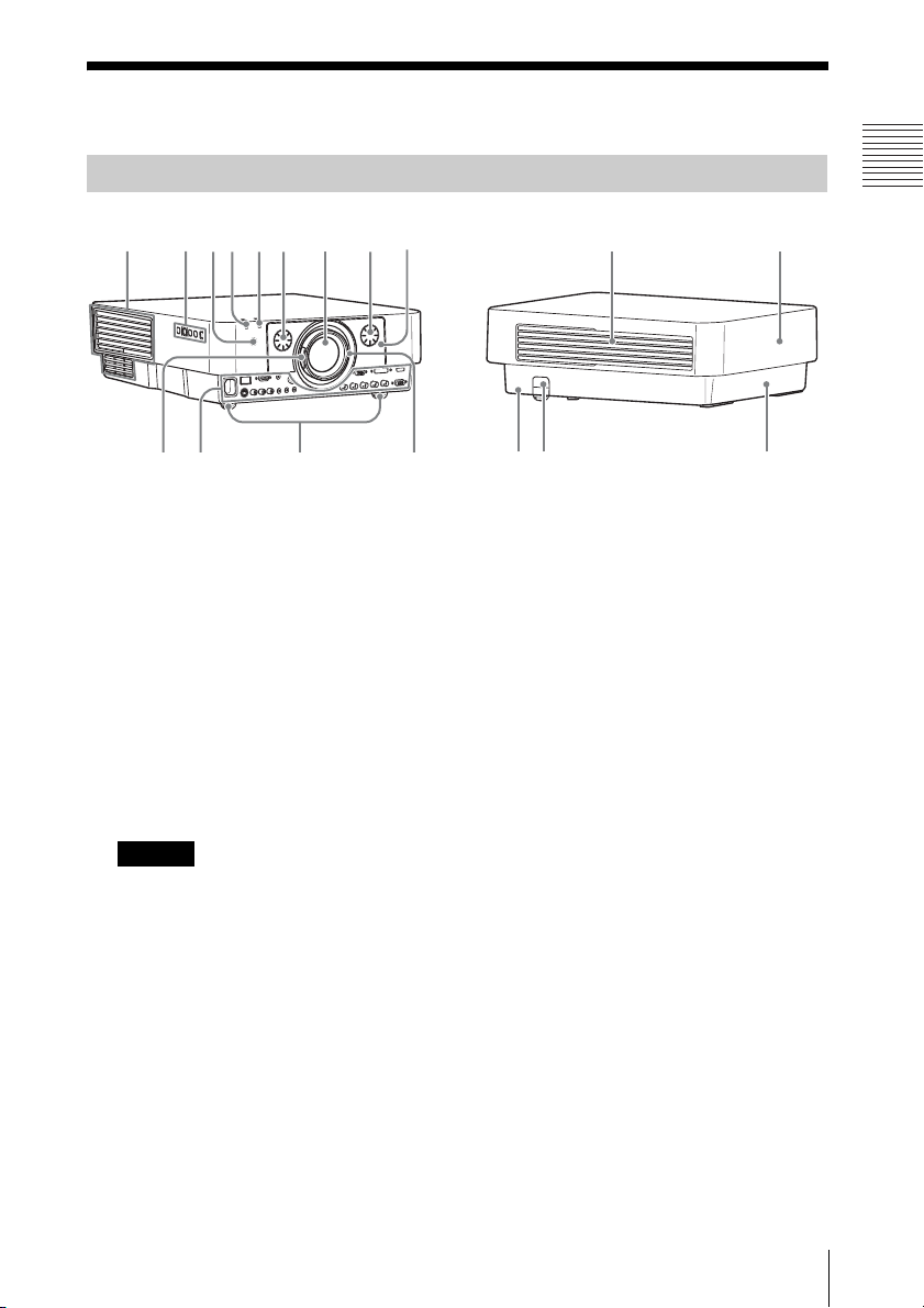
Location and Function of Controls
Main Unit
8
qa qd9q;4 1 4 5
s
a Lens (page 47)
b Focus ring (page 13)
c Zoom lever (page 13)
d Lens shift dial (page 13)
e Front panel (page 47)
f Rear panel (pages 44, 46)
g Ventilation holes (intake)
h Ventilation holes (exhaust)
Caution
Do not place anything near the ventilation
holes as this may cause internal heat
buildup. Do not place your hand near the
ventilation holes and the circumference as
this may cause injury.
f
7
qgqh
l Terminals (page 4)
m Remote control receiver
The remote control receivers are located
at the front and rear of the projector.
n Front feet (adjustable) (page 13)
o Antitheft lock
Connects to an optional antitheft cable
manufactured by Kensington.
For details, visit Kensington’s web site.
http://www.kensington.com/
p Antitheft bar
Connects to a commercially available
antitheft chain or wire.
6
qd
Overview
i ON/STANDBY indicator
(page 40)
j LAMP/COVER indicator
(page 40)
k Control panel (page 5)
Location and Function of Controls
3
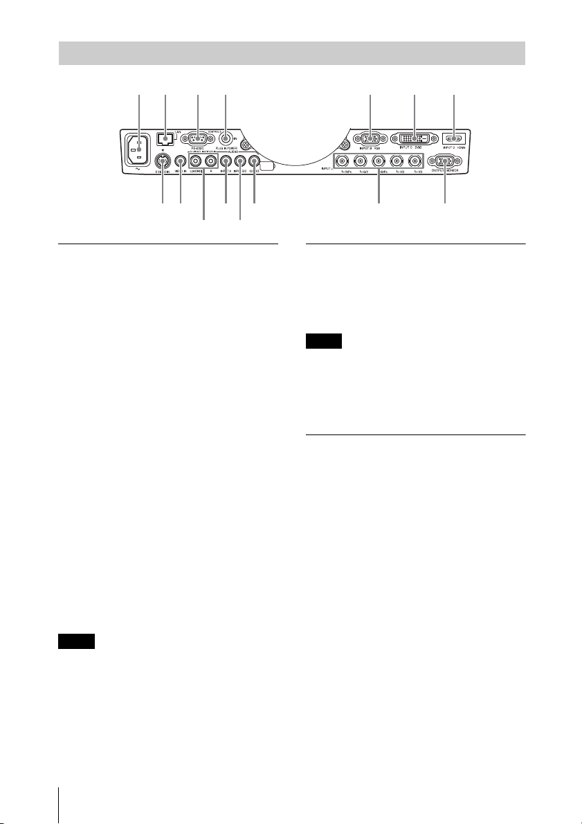
Terminals
56 23
qa 9
8q; 32 4
56 1 7 1 7
Input (page 8)
a INPUT A
Video: RGB/YPBPR input terminal
(RGB HD VD/YPBPR)
Audio: Audio input terminal (AUDIO)
b INPUT B
Video: RGB input terminal (RGB)
Audio: Audio input terminal (AUDIO)
c INPUT C
Video: DVI-D input terminal (DVI-D)
Audio: Audio input terminal (AUDIO)
d INPUT D (VPL-FH31 only)
Video: HDMI input terminal (HDMI)
Audio: HDMI input terminal (HDMI)
Output (page 11)
g OUTPUT
Video: Monitor output terminal
(MONITOR)
Audio: Audio output terminal (AUDIO)
Note
This terminal outputs the projected image or
audio. The image is output as a computer signal
input from the RGB input terminal (INPUT A,
INPUT B) or a video signal input from the
YPBPR input terminal (INPUT A).
Others
h RS-232C terminal
RS-232C compatible control terminal
e S VIDEO (S VIDEO IN)
Video: S video input terminal
Audio: Audio input terminal (AUDIO L
[MONO]/R)
f VIDEO (VIDEO IN)
Video: Video input terminal
Audio: Audio input terminal (AUDIO L
[MONO]/R)
Notes
• The audio input terminals of the projector are
for output to external equipment. Connect
external audio equipment to output an
audio (page 11).
• The audio inputs of INPUT B and INPUT C
are shared. The audio inputs of S VIDEO
and VIDEO also are shared.
4
Location and Function of Controls
i LAN terminal (page 33)
j CONTROL S input terminal (DC
power supply) (CONTROL S IN
PLUG IN POWER)
Connects to the CONTROL S output
terminal on the supplied Remote
Commander with a connecting cable
(stereo mini plug (not supplied)) when
using it as a wired Remote Commander.
You do not need to install batteries in the
Remote Commander, as the power is
supplied from this terminal.
k AC IN (∼) socket
Connects the supplied AC power cord.
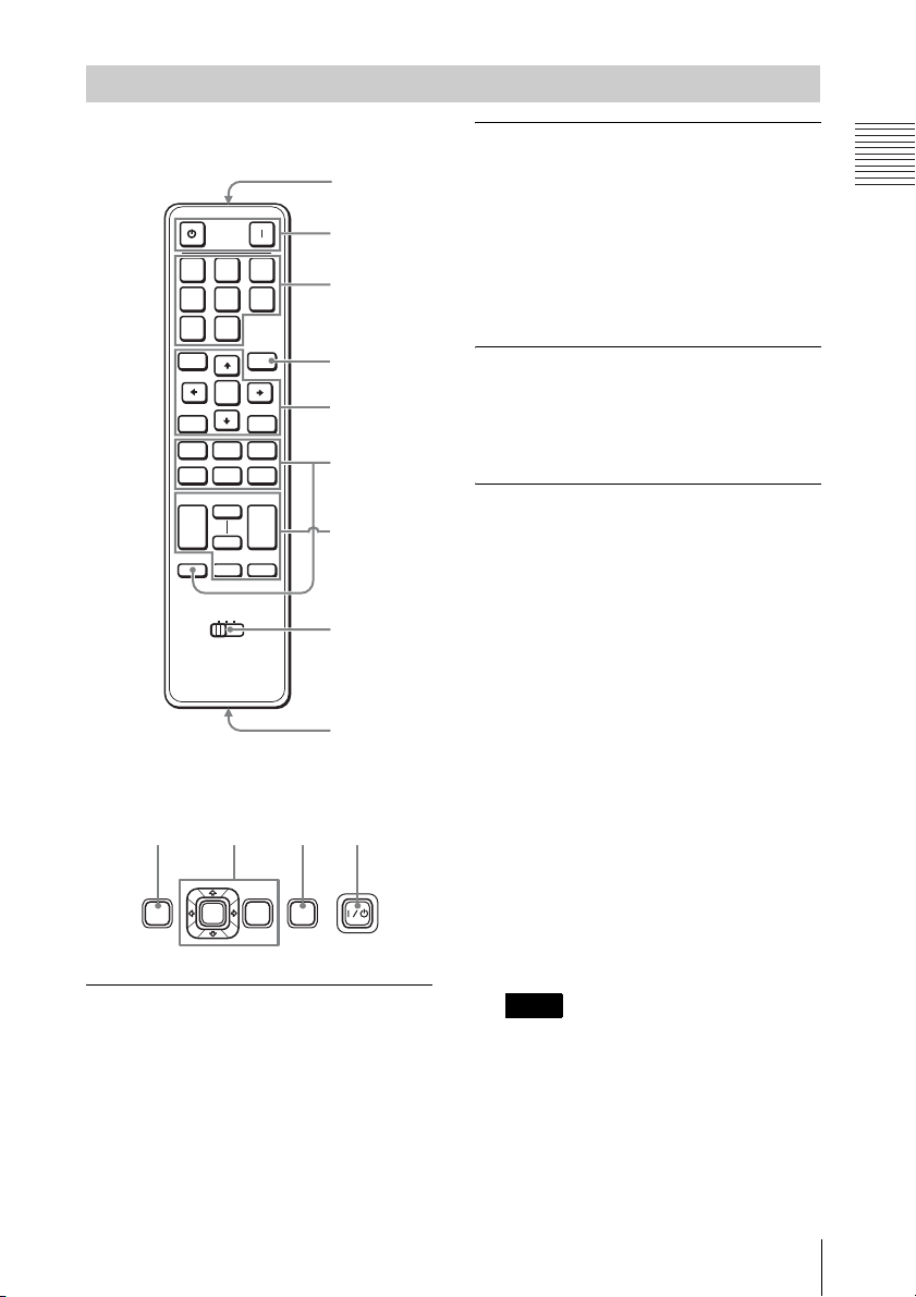
Remote Commander and Control Panel
9
Remote Commander
7
ONSTANDBY
INPUT
ABC
DEF
S
VIDEO
VIDEO
ENTER
KEY-
STONE
MUTING
PIC
AUDIO
TWIN FREEZEAPA
ID MODE
1 2 3
ECO
MODE
RESETRETURN
SHIFTZOOMFOCUS
+
–
MENU
ASPECT PATTERN
D ZOOM VOLUME
+
–
1
2
6
3
4
5
8
Control Panel
3126
ECO
ENTER
MODE
MENU INPUT
a Turning on the power/Going to
standby
? (On) key
1 (Standby) key
b Selecting an input signal
(page 12)
INPUT key (main unit)
Direct input select keys (Remote
Commander)
VPL-FH31: The E and F keys are not
used with this projector.
VPL-FX37/FX35/FX30: The D, E, and
F keys are not used with this projector.
c Operating a menu (page 19)
ENTER /V/v/B/b (arrow) keys
MENU key
RETURN key
RESET key
d Adjusting the image (page 13)
FOCUS key
This function is not provided in this
projector.
ZOOM key
This function is not provided in this
projector.
SHIFT key
This function is not provided in this
projector.
ASPECT key (pages 22, 24)
Changes the aspect ratio of the projected
image.
KEYSTONE key (page 14)
PATTERN key (page 13)
APA (Auto Pixel Alignment) key
Automatically adjusts a picture to its
clearest while a signal is input from a
computer. You can cancel the adjustment
by pressing the APA key again while
adjusting.
Note
Use this key when inputing a computer
*
signal via the RGB input terminal
(INPUT A, INPUT B).
Overview
*
Location and Function of Controls
5
e Using various functions during
projecting
D ZOOM (Digital Zoom) +/– key
*1
Enlarges a portion of the image while
projecting.
1 Press the D ZOOM + key to display
the digital zoom icon on the projected
image.
2 Press the V/v/B/b keys to move the
digital zoom icon to the point on the
image you wish to enlarge.
3 Press the D ZOOM + key or the D
ZOOM – key repeatedly to change the
enlargement ratio. The image can be
enlarged up to 4 times.
Press the RESET key to restore the
previous image.
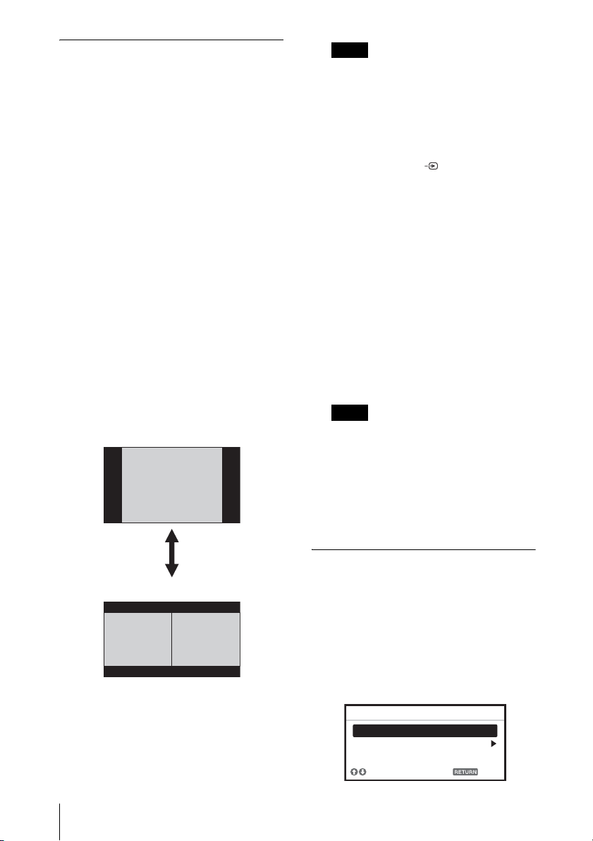
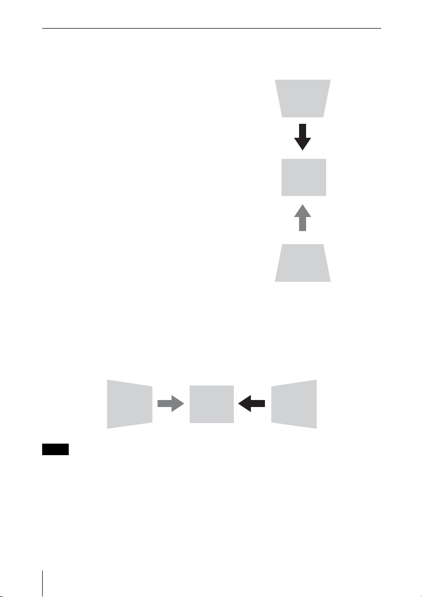
TWIN (Twin Picture) key
(VPL-FH31 only)
You can project the images from two
input signals on the screen as a main
picture and subpicture at the same time.
To switch between one and two pictures,
press the TWIN key on the Remote
Commander.
One picture display
TWIN key
Two pictures display
(A) Main picture (B) Subpicture
You can select the image to project to the
main picture.
The subpicture is preset to display the
image from INPUT B.
For details on combinations of input
signals, see “Combinations of Input
Signals” on page 60.
Notes
• When displaying a two pictures, the ?
(On) key, 1 (standby) key, INPUT key,
and MUTING (PIC) key are available.
• When “Screen Aspect” (page 29) is set
to “4:3,” the two picture function is not
available.
• When displaying a two pictures, the
input signal icon does not appear in
the input select window (page 12).
• Picture settings set for one pictures may
not be reflected as two pictures.
MUTING key
PIC: Cuts off the image. Press again to
restore the image.
AUDIO: Mutes the audio output. Press
again to restore the previous volume.
VOLUME +/– key
For adjusting the volume output from
the audio output terminal of the
projector.
FREEZE key
*2
Pauses a projected image. Press again to
restore the image.
Notes
*1: Use this key when inputting a
computer signal. But it may not be
enabled, depending on the resolution
of the input signal and when
displaying a two pictures (VPL-FH31
only).
*2: Use this key when inputting a
computer signal.
f Setting the energy–saving mode
easily
ECO MODE key
“Lamp Mode,” “Power Saving Mode,”
and “Standby Mode” for energy-saving
can be set easily.
1 Press the ECO MODE key to display
the ECO Mode menu.
ECO Mode Menu
ECO Mode
ECO
User
Sel Back
6
Location and Function of Controls
2 Press the V/v key or ECO MODE key
to select ECO or User mode.
ECO: Sets each mode to the optimum
energy-saving value.
Lamp Mode: Standard
Power Saving Mode: Standby
Standby Mode: Low
(go to step 6)
User: Sets each item of the energy-
saving mode menu as you desire
(go to step 3).
3 Select “User” then press the b key.
The setting items appear.
User
Lamp Mode Standard
Power Saving Mode Off
Standby Mode Standard
Set
Sel Back
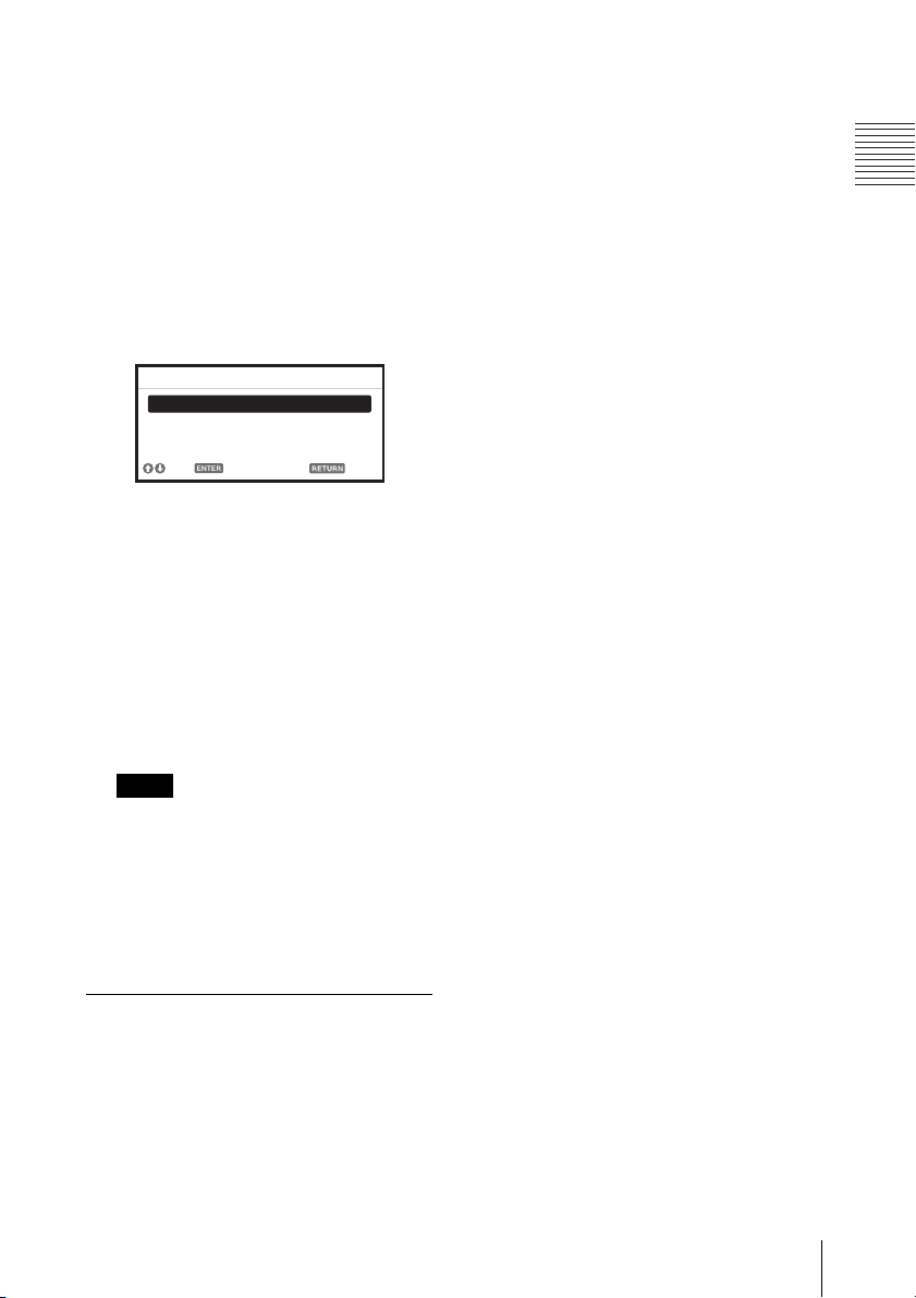
4 Press the V/v key to select the ECO
Mode item then press the b key or the
ENTER key.
5 Press the V/v key to select the setting
value.
6 Press the RETURN key to restore the
previous image.
For details on ECO Mode settings, see
“Lamp Mode” (page 26) on the Function
menu and “Standby Mode” (page 28)
and “Power Saving Mode” (page 28) on
the Connection/Power menu.
the projector with the same ID mode as
that of the Remote Commander.
i CONTROL S output terminal
Connects to the CONTROL S input
terminal on the projector with a
connecting cable (stereo mini plug (not
supplied)) when using the Remote
Commander as a wired one.
You do not need to install batteries in the
Remote Commander, as the power is
supplied from the projector.
About Remote Commander operation
• Direct the Remote Commander toward the
remote control receiver.
• The shorter the distance between the
Remote Commander and the projector is,
the wider the angle within which the
Remote Commander can control the
projector becomes.
• If there is any obstruction between the
Remote Commander and the remote
control receiver on the projector, the
projector may not be able to receive
signals from the Remote Commander.
Overview
Note
If you set “ECO Mode” to “ECO,” or
“Standby Mode” (in “User”) to “Low,”
the network control function will be
disabled in standby mode. If the external
control is being performed by using the
network or network control function, do
not select “ECO,” or do not set “Standby
Mode” (in “User”) to “Low.”
Others
g Infrared transmitter
h ID MODE 1/2/3 switch (page 27)
Sets an ID mode of the Remote
Commander. If you assign a different ID
number to each projector when multiple
projectors are used, you can control only
Location and Function of Controls
7
B Preparation
Connecting the Projector
Notes
• Turn off all equipment before making any connections.
• Use the proper cables for each connection.
• Insert the cable plugs firmly; Loose connections may reduce performance of picture signals or
cause a malfunction. When pulling out a cable, be sure to grip it by the plug, not the cable itself.
• For more information, refer also to the instruction manuals of the equipment you are connecting.
• Use a no-resistance audio cable.
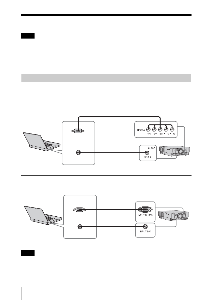
Connecting a Computer
Connection with a computer is explained for each input signal.
INPUT A
For connection when there is some distance between a computer and the projector.
Mini D-sub 15-pin
– BNC cable
(not supplied)
RGB output
terminal
Computer
Audio output
terminal
Audio cable
(Stereo mini plug)
(not supplied)
INPUT B
For connecting a computer with an RGB output terminal.
RGB output
terminal
Audio output
terminal
Computer
Note
Mini D-sub 15-pin
cable
(not supplied)
Audio cable
(Stereo mini plug)
(not supplied)
It is recommended that you set the resolution of your computer to 1920 × 1200 pixels (VPL-FH31)
or 1024 × 768 pixels (VPL-FX37/FX35/FX30) for the external monitor.
8
Connecting the Projector
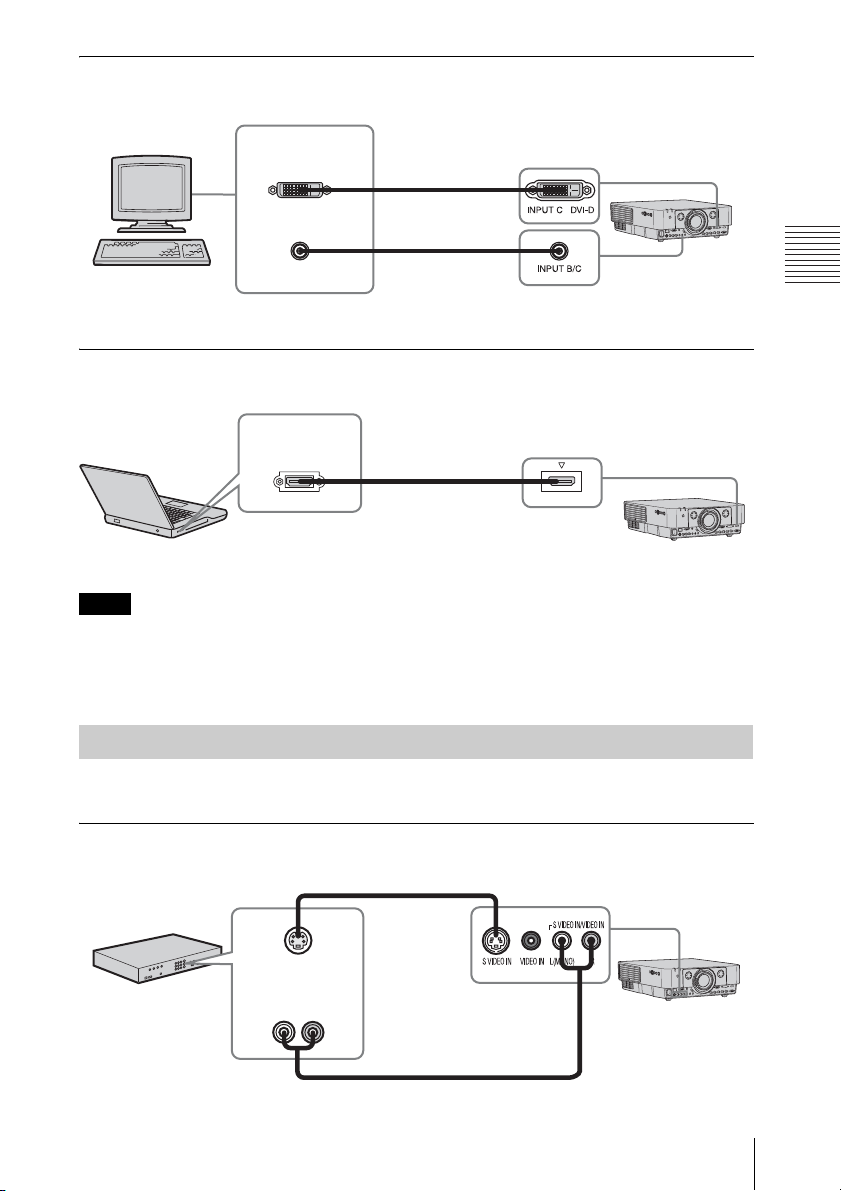
INPUT C
For connecting a computer with a DVI-D output terminal.
DVI-D output
terminal
Audio output
terminal
Computer
DVI-D cable
(not supplied)
Audio cable
(Stereo mini plug)
(not supplied)
INPUT D (VPL-FH31 only)
For connecting a computer with a HDMI output terminal.
HDMI output
terminal
HDMI cable
(not supplied)
Computer
Notes
INPUT D HDMI
• The HDMI terminal of this projector is not compatible with DSD (Direct Stream Digital) Signal
or CEC (Consumer Electronics Control) Signal.
• Use HDMI-compatible equipment which has the HDMI Logo.
• Use a high speed HDMI cable(s) on which the cable type logo is specified. (Sony products are
recommended.)
Preparation
Connecting a Video Equipment
Connections with a VHS video deck, DVD player, or BD player are explained for each input
signal.
S VIDEO IN
For connecting video equipment with an S-video output terminal.
S video cable
(not supplied)
S video output
terminal
Video equipment
Audio output
terminal
Audio cable (Phono plug × 2) (not supplied)
Connecting the Projector
9
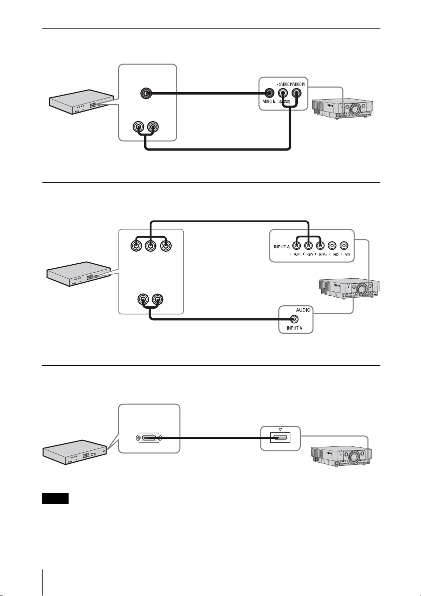
VIDEO IN
For connecting video equipment with a video output terminal.
Video equipment
Video output
terminal
Audio output
terminal
Audio cable (Phono plug × 2) (not supplied)
Video cable
(not supplied)
INPUT A
For connection when there is some long distance between the video equipment and projector.
Component – BNC
cable (not supplied)
BPR output
YP
terminal
Audio output
Video equipment
terminal
Audio cable (Phono plug
× 2 – stereo mini plug)
(not supplied)
INPUT D (VPL-FH31 only)
For connecting video equipment with a HDMI output terminal.
HDMI output
terminal
HDMI cable
(not supplied)
Video equipment
INPUT D HDMI
Notes
• The HDMI terminal of this projector is not compatible with DSD (Direct Stream Digital) Signal
or CEC (Consumer Electronics Control) Signal.
• Use HDMI-compatible equipment which has the HDMI Logo.
• Use a high speed HDMI cable(s) on which the cable type logo is specified. (Sony products are
recommended.)
10
Connecting the Projector
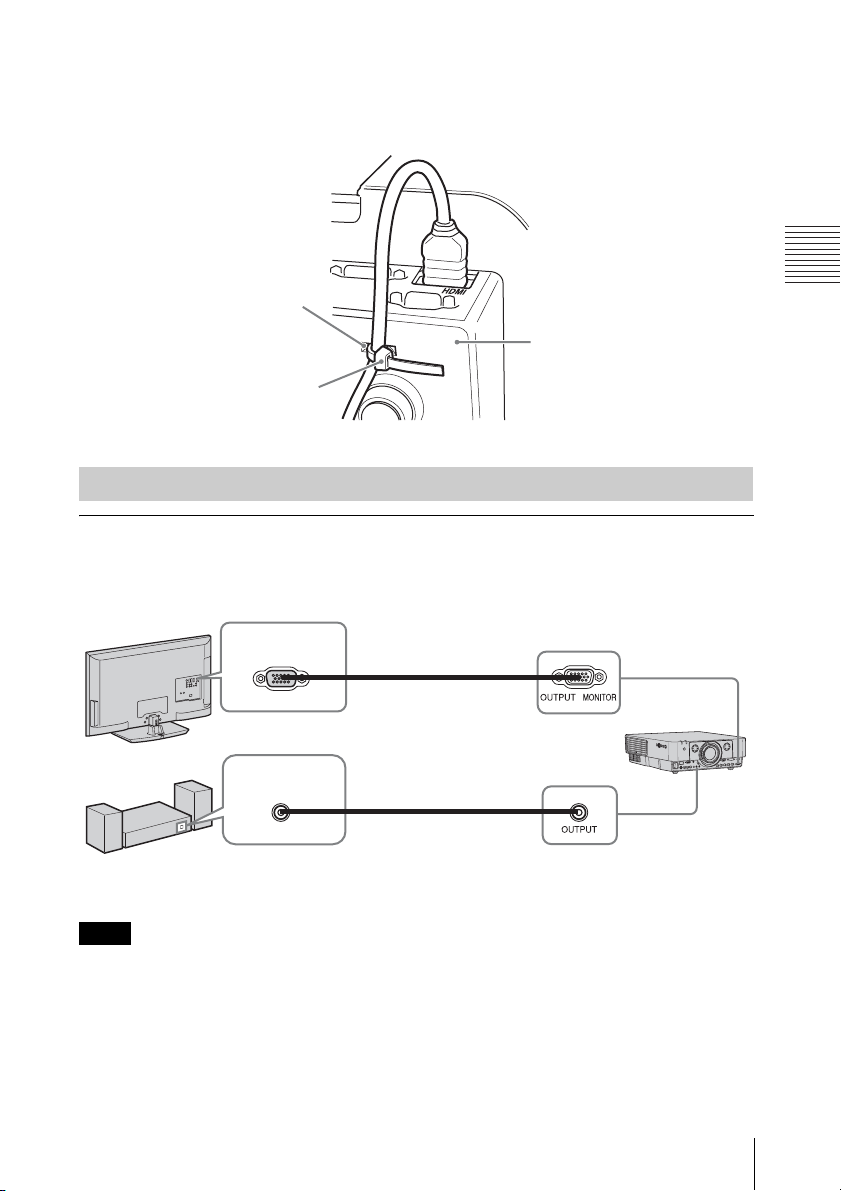
To attach the HDMI cable
Fix the cable to the cable tie holder at the bottom of the projector, using a commercially
available cable tie, as in the illustration.
Use a cable tie of less than 1.9 mm × 3.8 mm in thickness.
Cable tie holder
Bottom of the projector
Cable tie
(commercially
available)
Connecting an External Monitor and Audio Equipment
OUTPUT
Projected images and input audio can be output to display equipment such as a monitor and
audio equipment such as speakers with a built-in amplifier.
Display equipment
Audio equipment
RGB input
terminal
Audio input
terminal
Mini D-sub 15pin cable
(not supplied)
Audio cable
(stereo mini plug)
(not supplied)
Preparation
Note
This terminal outputs the projected image or audio. The image is output as a computer signal input
from the RGB input terminal (INPUT A, INPUT B) or a video signal input from the YPBPR input
terminal (INPUT A).
Connecting the Projector
11
B Projecting/Adjusting an Image
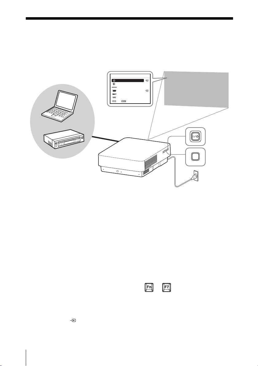
Projecting an Image
The size of a projected image depends on the distance between the projector and screen. Install
the projector so that the projected image fits the screen size. For details on projection distances
and projected image sizes, see “Projection Distance and Lens Shift Range” (page 61).
Input select window
5
Input
Video
S-Videoo
4
6
Computer
Input-A
Input-B
Input-C
Input-D
Sel Skip
2
Video equipment
1 Plug the AC power cord into a wall
outlet.
2 Connect all equipment to the projector
(page 8).
3 Turn on the projector.
Press the ?/1 key on the main unit or the
? key on the Remote Commander.
4 Turn on the connected equipment.
5 Select the input source.
Press the INPUT key on the projector to
display the input select window. Press
the INPUT key repeatedly or the V/v
key to select an image to be projected.
The signal icon appears on the right
side in the input select window when a
signal is input.
3
INPUT
5
Projector
You can select the input source using
Direct input select keys on the Remote
Commander
1
(page 5).
Wall outlet
6 Switch your computer to output to
external display by changing your
computer’s setting.
How to switch the computer to output to
the projector varies, depending on the
type of computer.
(Example)
+
7 Adjust the focus, size, and position of
the projected image (page 13).
12
Projecting an Image
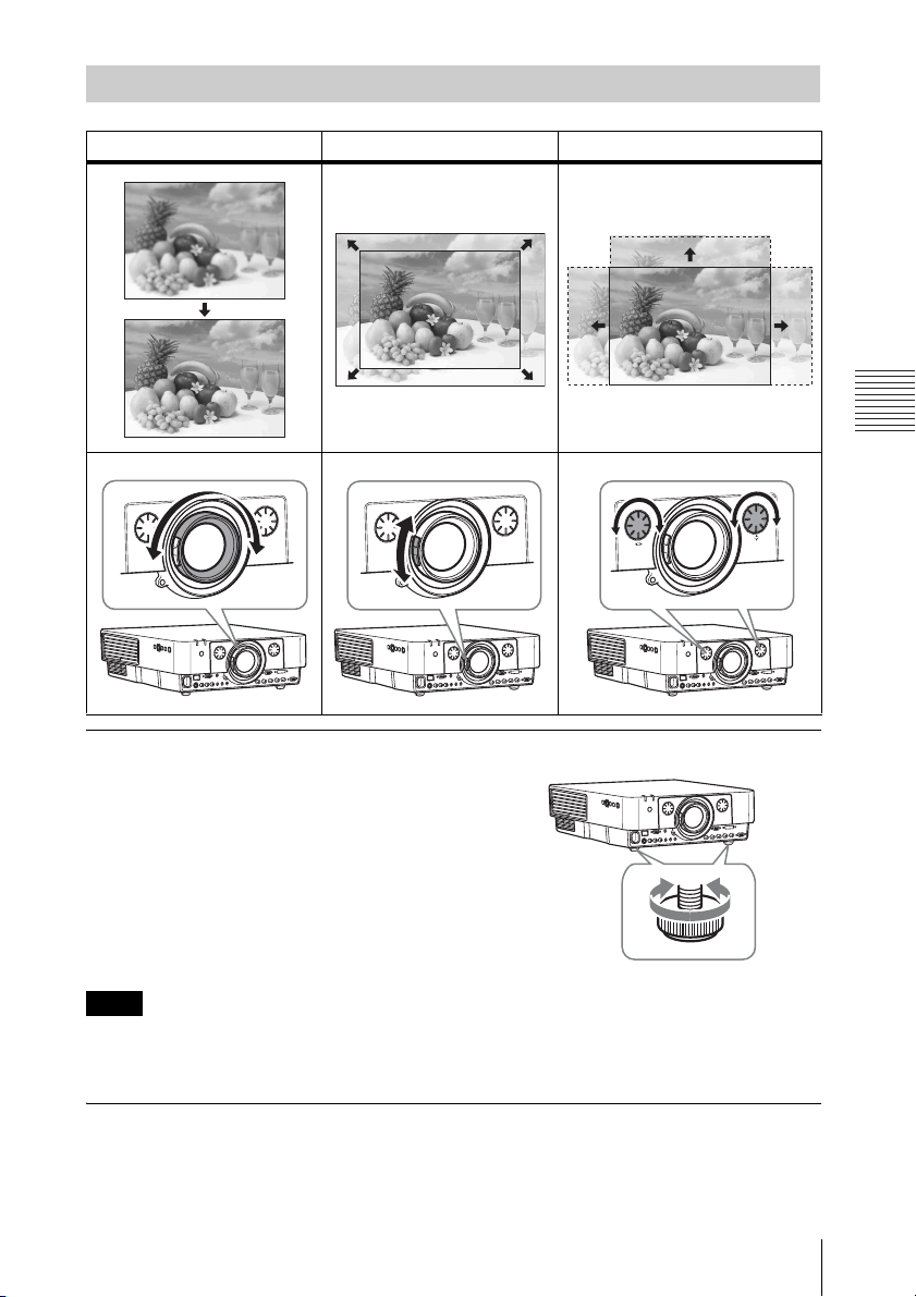
Adjusting the Focus, Size, and Position of the Projected image
Focus Size (Zoom) Position (Lens shift)
Projecting/Adjusting an Image
Adjusting the tilt of the projector with the front feet (adjustable)
When the projector is installed on an uneven
surface and the projected position is low, you
can adjust using the front feet (adjustable).
To correct any trapezoidal distortion of the
projected image, use the Keystone
correction feature (pages 14,
Notes
• Be careful not to let the projector down on your fingers.
• Do not push hard on the top of the projector with the front feet (adjustable) extended.
• Since the Keystone adjustment is an electronic correction, the image may be deteriorated.
29).
Displaying a pattern for adjusting an image
You can display a pattern for adjusting the projected image with the PATTERN key on the
Remote Commander. Press the PATTERN key again to restore the previous image.
Projecting an Image
13
Correcting for trapezoidal distortion of the projected image (Keystone
adjustment)
If the screen is tilted, or you are projecting from an oblique angle, perform keystone adjustment.
1 Press the KEYSTONE key on the
Remote Commander once or select “V
Keystone” in the Installation menu to
display the adjustment menu.
2 Adjust the value using V/v/B/b.
The higher the setting, the narrower the
top of the projected image. The lower
the setting, the narrower the bottom of
the projected image.
If the projected image is trapezoidally-distorted in the lateral plane (VPL-FH31
only)
1 Press the KEYSTONE key on the
Remote Commander twice, or select
“H Keystone” in the Installation menu
to display the adjustment menu.
2 Adjust the value using V/v/B/b.
The higher the setting, the narrower the
right side of the projected image. The
lower the setting, the narrower the left
side of the projected image.
Increase setting
Decrease setting
Decrease setting Increase the setting
Notes
• Since the Keystone feature is electronic, image deterioration may occur.
• Depending on the position adjusted with the lens shift feature, using the Keystone feature may
change the aspect ratio of the original image, or the projected image may be distorted.
• If keystone correction is performed using the KEYSTONE key, the Warp correction feature (if
enabled) will be canceled.
14
Projecting an Image
Correcting image twist (Warp
correction feature) (VPL-FH31 only)
You can correct image twist with the warp
correction feature.
1 Press the KEYSTONE key on the
Remote Commander three times, or
select “Warping” in the Installation
menu, then select “Adjust.”
The guide is displayed.
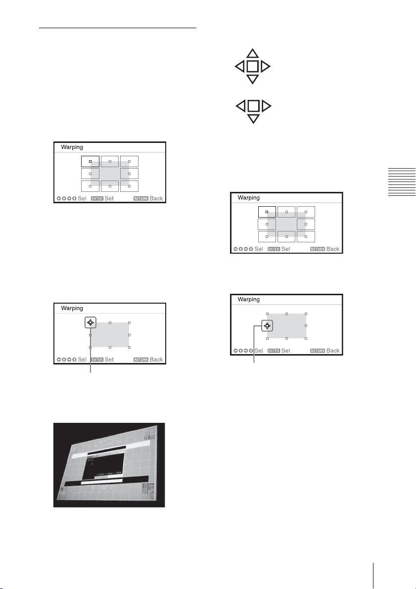
Selecting the corner(s) of the image
to be corrected
1 Move s using V/v/B/b to select the
corner you want to correct.
2 Press the ENTER key.
The cursor appears.
Example of cursor display:
Adjust in all directions
Leftward, rightward or
downward adjustment only
Correcting deflection 1 – left/right
sides of the image
1 Move s using V/v/B/b to select the
side you want to correct.
Press the ENTER key.
2
The cursor appears.
Projecting/Adjusting an Image
Adjust using this cursor
3 Adjust the position of the corner you
want to correct, using V/v/B/b.
The cursor will disappear when the
deflection range limit is reached.
Adjust using this cursor
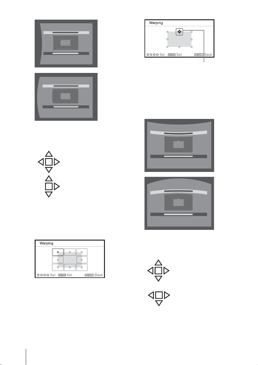
3 You can adjust the deflection of the
side, using V/v/B/b.
You can adjust the center point of
deflection using V/v. For the range of
deflection, use B/b. You can adjust the
left/right side independently.
Projecting an Image
15
The cursor will disappear if the
deflection range limit is reached.
Example of cursor display:
Adjust in all directions
Upward, downward, or
rightward adjustment only
Correcting deflection 2 – top/bottom
sides of the image
1 Move s using V/v/B/b to select the
side you want to correct.
Adjust using this cursor
3 You can adjust the deflection of the
side, using V/v/B/b.
You can adjust the center point of
deflection using B/b. For the range of
deflection, use V/v. You can adjust the
top/bottom independently.
The cursor will disappear if the
deflection range limit is reached.
Example of cursor display:
2 Press the ENTER key.
The cursor appears.
16
Projecting an Image
Adjust in all directions
Leftward, rightward or
downward adjustment only
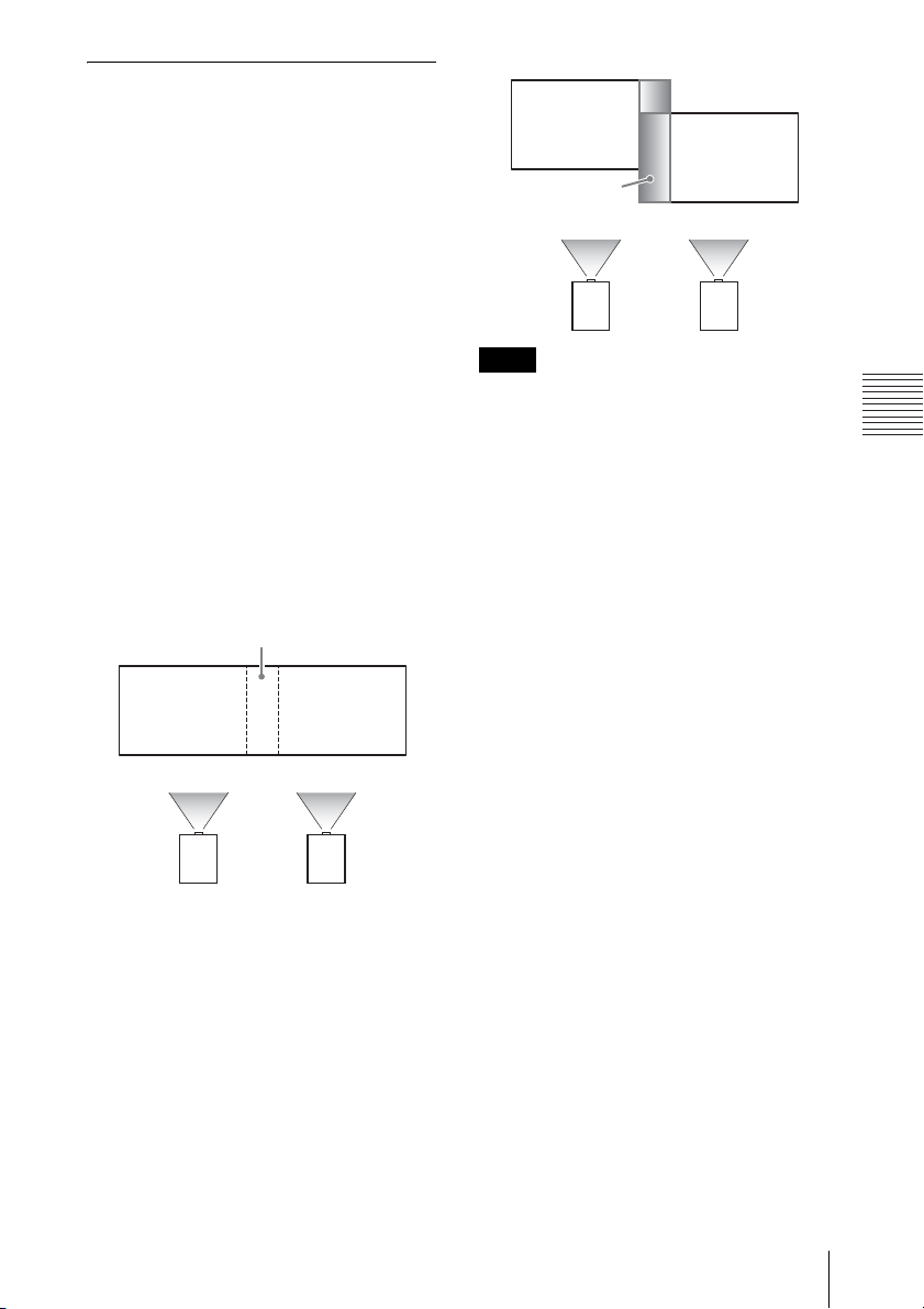
Setting the blending function to
project from multiple projectors
(VPL-FH31 only)
1 Install the projectors.
Input a pattern, etc., to adjust the
projected positions from multiple
projectors.
Set a different ID mode for each
projector (page 27).
2 Enable the Edge Blending function.
Display the main menu to set “Edge
Blending” to “On” in the Installation
menu.
3 Set the position of blending.
Choose the position (top/bottom/left/
right) for blending.
4 Assign the blending width.
Set the blending width according to the
overlapping range for the source signal.
Assign the position and width here.
Blend Gamma
correction
Notes
• The procedure shown above is for general
guidance. Your own installation may vary
according to the situation.
• In the case of multiple projectors, use the
color matching function (page 31) to adjust
for differences in color and brightness.
Note that more detailed adjustment for Edge
Blending is possible using a PC application.
For more details, consult with qualified Sony
personnel.
• When multiple projectors are set up in a line,
the temperature inside the projectors may
increase due to exhaust vent proximity, and
an error indication may result.
In this case, space the projectors farther apart
and/or install deflection partitioning between
them.
For more details, consult with qualified Sony
personnel.
Projecting/Adjusting an Image
5 Adjust using “Zone Black Level Adj.”
Adjust each correction zone by “Zone
Black Level Adj.” for the most uniform
black level between each zone.
During this adjustment, a black image is
automatically projected.
6 Set “Blend Gamma.”
Select the gamma mode in which the
overlapping of images is least
noticeable.
Projecting an Image
17

Turning Off the Power
1 Press the ?/1 key on the main unit or
the 1 key on the Remote Commander.
The message appears if you press the ?/
1 key on the main unit. Press it again
according to the message.
The fan continues to run for a while to
reduce internal heat.
Note
Do not turn off the projector soon after the
lamp lights. It may cause a malfunction of
the lamp (does not light, etc.).
2 Unplug the AC power cord from the
wall outlet.
You may unplug the AC power cord
before the fan stops.
Note
To move the projector just after turning it
off, be sure to wait until the fan stops
before unplugging the AC power cord.
Unplugging the AC power cord before the
fan stops may cause a malfunction.
To erase the confirmation message
The message disappears if you press any key
other than the ?/1 key on the main unit or 1
key on the Remote Commander, or if you do
not press any key for a while.
To turn off the power with the key
on the main unit without a
confirmation message being
displayed
Hold the ?/1 key on the main unit pressed
for a few seconds.
18
Projecting an Image
B Adjustments and Settings Using a Menu
Using a MENU
Note
The menu displays used for the explanation below may be different depending on the model you are
using.
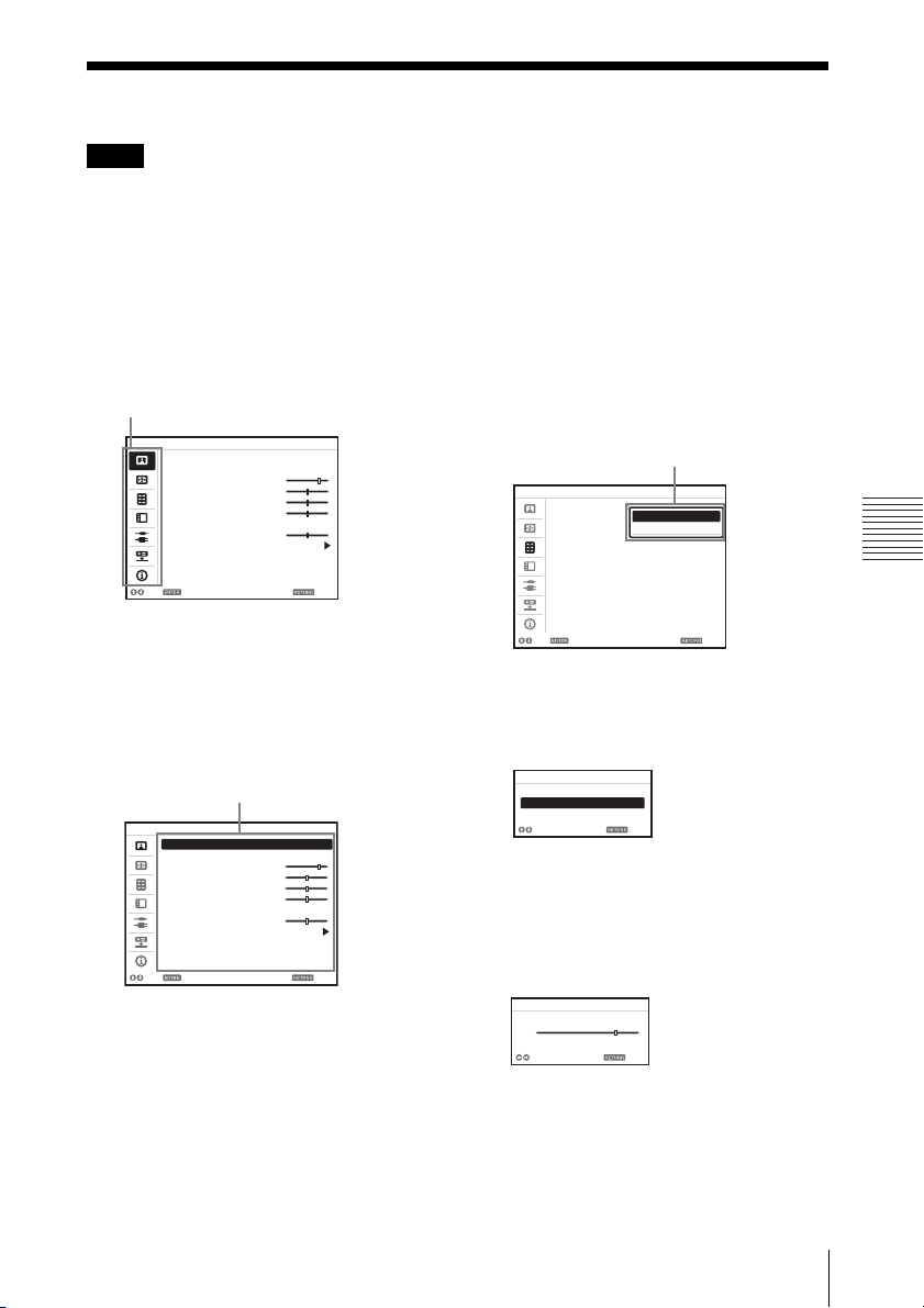
1 Press the MENU key to display the
menu.
2 Select the setting menu.
Use the V or v key to select the setting
menu then press b or ENTER key.
Setting menu
Picture
Picture Mode Standard
Reset
Contrast 80
Brightness 50
Color 50
Hue 50
Color Temp. Middle
Sharpness 50
Expert Setting
Sel Set Back
3 Select the setting item.
Use the V or v key to select the setting
menu then press b or ENTER key.
To return to the selection screen of the
setting menu, press the B key or the
RETURN key.
Setting items
Picture
Picture Mode Standard
Reset
Contrast 80
Brightness 50
Color 50
Hue 50
Color Temp. Middle
Sharpness 50
Expert Setting
Sel Set Back
4 Make the setting or adjustment for the
selected item.
Menu operation differs depending on the
setting item. If the next menu window is
displayed, select the item according to
the operations in step 3 and then press
the ENTER key to register the setting.
To return to the selection screen of the
setting items, press the B key or the
RETURN key. Also, to reset the setting
value of an item to its factory preset
value, press the RESET key during
setting or adjusting.
Using a pop-up menu
Press the V/v/B/b key to select an item.
Press the ENTER key to register the
setting. The previous screen is restored.
Selecting items
Function
Audio Output Volume
Smart APA Standard
CC Display
Lamp Mode Standard
Lamp Timer Reset
Background Blue
Start Up Image On
Sel Set Back
On
Off
Using the setting menu
Press the V or v key to select the item.
Press the ENTER key to register the
setting. The previous screen is restored.
Picture Mode
Dynamic
Standard
Presentation
Sel Back
Using the adjustment menu
To increase the number, press the V or b
key and to decrease the number, press
the v or B key. Press the ENTER key to
register the setting. The previous screen
is restored.
Contrast
Min
80
Adjust Back
Max
5 Press the MENU key to clear the
menu.
The menu disappears automatically if no
key is pressed for a while.
Adjustments and Settings Using a Menu
Using a MENU
19

The Picture Menu
For adjusting the picture for each input signal.
Setting items Description
Picture Mode Dynamic: Emphasizes the contrast to produce a “dynamic” picture.
Reset The picture settings are initialized to their factory preset values.
Contrast The higher the setting, the greater the contrast. The lower the setting, the lower
Brightness The higher the setting, the brighter the picture. The lower the setting, the darker
*2 *4
Color
*2 *4 *5
Hue
Color Temp.*3High/Middle/Low: The higher the temperature, the more bluish the picture.
Sharpness
Expert Setting
Film
Mode
Black Level
Adj.
(Adjust)
Gamma
Mode
Standard: Makes the picture be natural and well balanced.
Presentation
*1
: Makes the picture bright to suit for a presentation.
However, “Picture Mode” and “Custom1,” “Custom2,” and “Custom3” of
“Color Temp.” do not return to the factory preset values.
the contrast.
the picture.
The higher the setting, the greater the intensity. The lower the setting, the lower
the intensity.
The higher the setting, the more greenish the picture becomes. The lower the
setting, the more reddish the picture becomes.
The lower the temperature, the more reddish the picture.
Custom1/ Custom2/ Custom3: An adjusted color temperature setting can be
stored for each item.
The factory settings are Custom1: High, Custom2: Middle, Custom3: Low.
*6
The higher the setting, the sharper the picture. The lower the setting, the softer
the picture.
Auto: Precisely reproduces the image from a film source to suit the original
*2 *7
film source. Normally, select this option.
Off: Select this option if the images are rough around the edges when “Auto” is
selected.
High/Low/Off: Emphasizes dark portions of the projected image to suit your
taste.
*2
Graphics1: Improves the correction of halftones to give a brighter image. This
*1
can be useful when projecting colored images, such as photos, in a bright
location.
Graphics2: Improves the reproduction of halftones. This reproduces colored
images, such as photos, in more natural tones.
Text: Contrasts black and white. Suitable for images that contain lots of text.
DICOM GSDF Sim.
*8
: Gamma setting is in accordance with the Grayscale
Standard Display Function (GSDF) of the Digital Imaging and
Communications in Medicine (DICOM) standards.
Notes
*1: When a computer signal is input, this option is available.
*2: When a video signal is input, this option is available.
*3: When “Picture Mode” is set to the item other than “Presentation,” this option is available.
*4: When a B & W signal is input, this option is not available.
20
The Picture Menu

*5: When an analog TV signal is input, this option may not available, depending on the color system.
*6: When a video signal is input, this option is available (VPL-FX37/FX35/FX30).
*7: When a progressive signal is input, this option is not available.
*8: Available when a computer signal is input from the DVI-D input terminal (INPUT C) and HDMI
input terminal (INPUT D). This projector is not to be used as a device for medical diagnosis.
This projector is not to be used as a device for medical diagnosis (VPL-FH31).
Adjustments and Settings Using a Menu
The Picture Menu
21

The Screen Menu
For adjusting the size, position, and aspect ratio of the projected image for each input signal.
Setting items Description
*1
Aspect
When the
computer
signal is
input
When the
video signal
is input
V Center
*2 *3
Vertical Size
Over Scan
*3
Adjust Signal
APA
Phase
Pitch
Shift
*4 *5
*4
*6
Changes the aspect ratio of the projected image. (page 24).
Full1: Displays the image to fit the maximum projected image size without
changing the aspect ratio of the input signal.
Full2: Displays the image to fit the maximum projected image size.
Normal: Displays the image on the center point of the projected image
without changing the resolution of the input signal or enlarging the image.
4:3: Displays the image to fit the maximum projected image size with an
aspect ratio fixed to 4:3.
16:9: Displays the image to fit the maximum projected image size with an
aspect ratio fixed to 16:9.
*2
Full
: Displays the image to fit the maximum projected image size.
Zoom: Display the center point of the projected image to zoom.
Adjust the whole projected image by moving up and down on the screen.
As the selected number increases, the screen moves up, and as the selected
number decreases, the projected image moves down.
*2 *3
Reduces or enlarges the image vertically.
The projected image is enlarged as the setting increases and reduced as the
setting decreases. If the subtitle of a movie, etc. cannot be seen, use this
together with “V Center.”
On/Off: Hides the outline of the image when set to “On.” Select “On” if
noise appears along the edge of the image.
*6
Adjusts the image of a computer signal. Use this item if the edge of the
image is cut and reception is bad.
Automatically adjusts the projected image to an optimum quality when you
press the ENTER key.
*4
Adjusts the dot phase of the display pixel and the input signal. Set to the
value where looks clearest.
The higher the setting, the wider the horizontal image elements (pitch). The
lower the setting, the narrower the horizontal image elements (pitch).
H: The higher the setting, the farther right the image is projected on the
screen. The lower the setting, the image farther left.
V: The higher the setting, the farther up the image is projected on the screen.
The lower the setting, the image farther down.
Notes
*1: • Note that if the projector is used for profit or for public viewing, modifying the original picture
by switching to the aspect mode may constitute an infringement of the rights of authors or
producers, which are legally protected.
• Depending on the input signal, setting items for aspect ratio or some other setting items cannot
be set in some cases, or changing the aspect ratio setting may have no effect.
• A part of the image may be displayed in black, depending on the setting item.
*2: Available for VPL-FH31 only.
22
The Screen Menu
 Loading...