

Sony VPL-FHZ101L, VPLFHZ131L Users Manual
5-016-717-11 (1)
Data Projector
Operating Instructions
Before operating the unit, please read this manual and supplied Quick Reference
Manual thoroughly and retain them for future reference.
VPL-FHZ131L/FHZ101L/FHZ91L
Not all models are available in all countries and area.
Please check with your local Sony Authorized Dealer.
© 2020 Sony Corporation

Table of Contents
Location of Controls
Main Unit ........................................................... 4
Terminals ........................................................... 5
Remote Commander and Control Panel ........... 6
Connections and Preparations
Connecting the Projector .................................. 8
Connecting to a Computer ........................... 8
Connecting to a Video Device ...................... 9
Connecting to an External Monitor .............10
Connecting to a Network Equipment ...........11
Connecting to a HDBaseT™ Device ..............11
Attaching the Projection Lens .......................... 13
Removing the Projection Lens .................... 13
Attaching the Terminal Cover ..........................14
Removing the Terminal Cover .....................14
Installing the Optional Adaptor .......................15
Projecting/Adjusting an Image
Projecting an Image .........................................16
Turning Off the Power .................................16
Adjusting the Projected Image ........................ 17
Focusing the image (Focus) ......................... 17
Adjusting the image size (Zoom) ................ 17
Adjusting the position of the image (Lens
shift) ........................................................... 17
Correcting for Trapezoidal Distortion of the
Projected Image (Keystone
Adjustment) ..............................................18
Correcting Image Twist (Warp Correction
Feature) .....................................................19
Blending Projections from Multiple Projectors
on a Screen ............................................... 20
Using Convenient Functions ............................21
Selecting the Stored Picture Settings (Picture
Position Function) (Specified Lens
Only) ..........................................................21
Enlarging a Part of the Image (Digital Zoom
Function) ...................................................22
Projecting Images with Two Pictures
Simultaneously (Two-Picture Display
Function) ...................................................22
Adjustments and Settings Using a Menu
Using a Menu ....................................................23
Projection Setting Menu .................................. 24
The Screen Menu ..............................................27
The Function Menu .......................................... 29
The Operation Menu ....................................... 30
The Connection/Power Menu .......................... 31
The Installation Menu .......................................33
The Information Menu .................................... 36
Network Features
Using Network Features ...................................37
Displaying the Control Window of the
Projector with a Web Browser ..................37
Confirming the Settings for the
Projector ................................................... 38
Operating the Projector from a
Computer ................................................. 38
Using the e-mail Report Function .............. 38
Configure the Network Settings ................. 40
Setting the Control Protocol of the
Projector ....................................................41
About the HTML Viewer Function .............. 43
Using the Software Update Function ......... 45
Error Handling
Indicators ......................................................... 46
Messages List .................................................. 48
Troubleshooting .............................................. 49
Others
Cleaning the Air Filter ....................................... 51
Updating the Software .....................................52
Updating the Software via the USB
Memory .....................................................52
Updating the Software via the Network ......52
2

Specifications ....................................................53
Pin assignment ........................................... 56
Acceptable Input Signals .............................57
Projection Distance and Lens Shift Range ...... 58
Dimensions .......................................................61
About Trademarks ........................................... 63
NOTICES AND LICENSES FOR SOFTWARE USED IN
THIS PRODUCT .............................................. 63
3
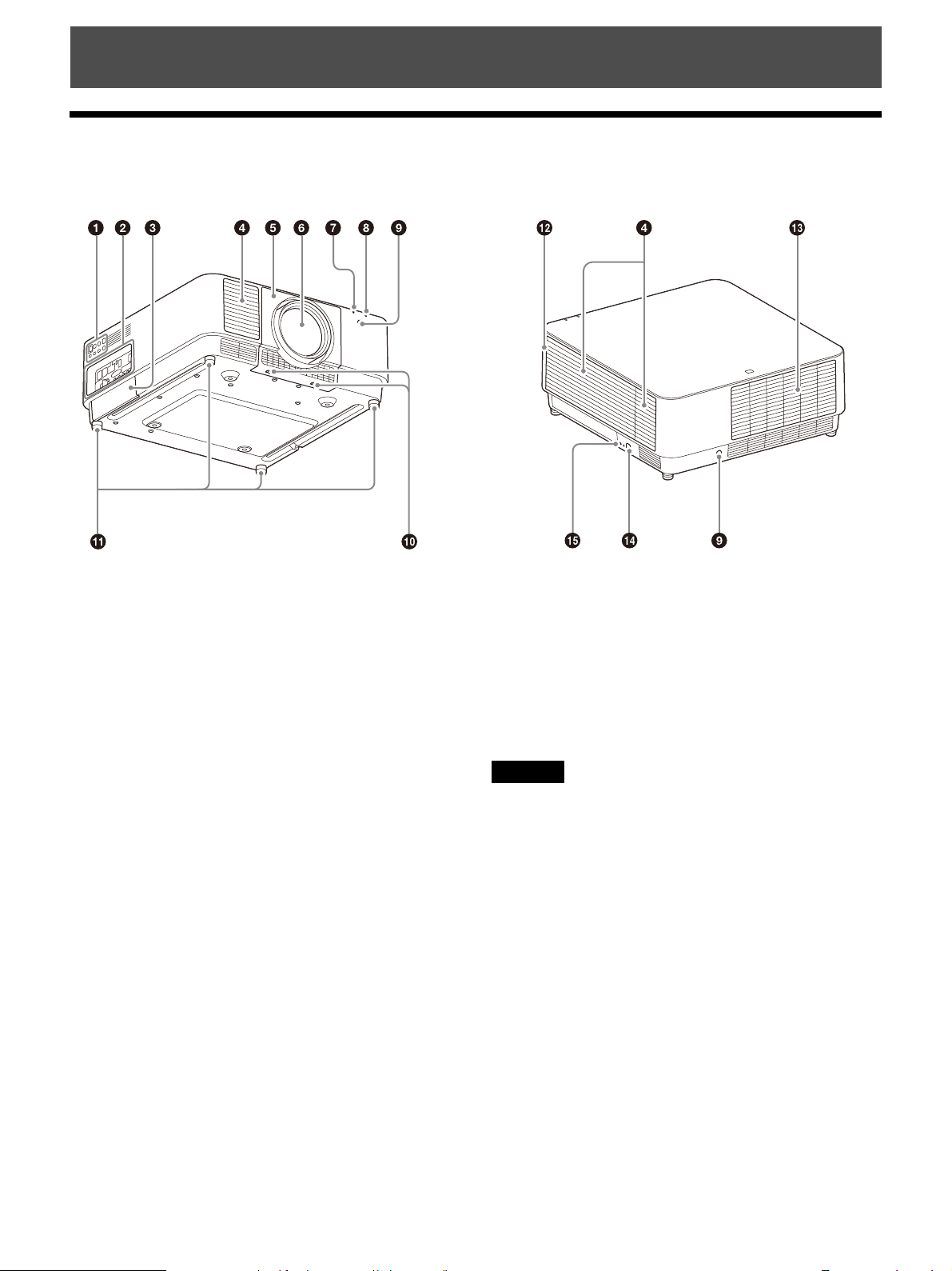
Location of Controls
Main Unit
Control panel (page 6)
Terminals (page 5)
Optional adaptor slot (page 15)
An optional adaptor (not supplied) can be
attached.
Ventilation holes (intake)
Lens cover (page 13)
Lens (not supplied) (page 13)
ON/STANDBY indicator (page 46)
WARNING indicator (page 46)
Remote control receiver
Located at the front and rear of the projector.
LENS COVER RELEASE buttons (page 13)
Adjustable feet (page 17)
Filter cover (page 51)
Antitheft bar
Connects to a commercially available antitheft
chain or wire.
Antitheft lock
Connects to an optional antitheft cable
manufactured by Kensington.
For details, visit the Kensington’s website.
http://www.kensington.com/
Caution
Do not place anything near the ventilation holes. The
temperature may rise inside the unit, leading to a possible
malfunction or fire. Do not place your hand or easily
deformable objects near the ventilation holes (exhaust)
and its vicinity. Doing so may cause burns or deformation.
Ventilation holes (exhaust)
4
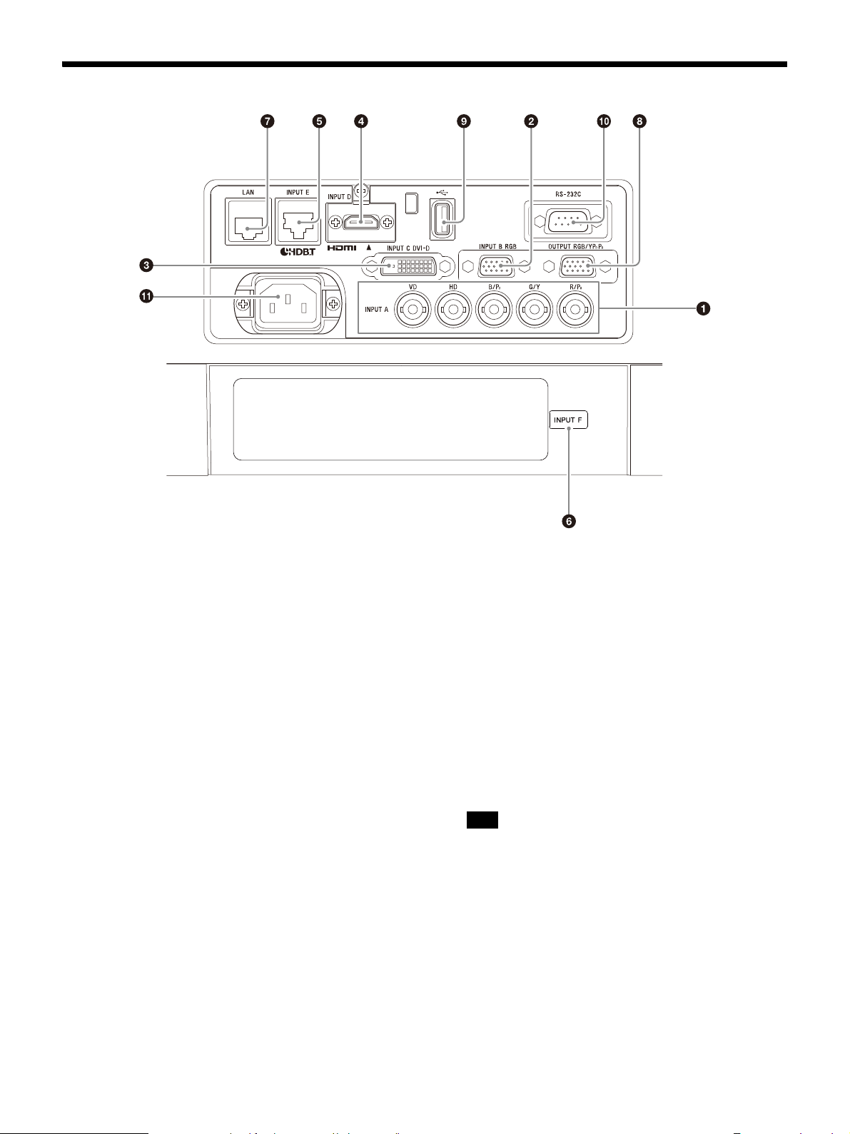
Terminals
INPUT A
Video: RGB/YP
(RGB HD VD/YP
BPR input terminal
BPR)
INPUT B
Video: RGB input terminal (RGB)
INPUT C
Video: DVI-D input terminal (DVI-D)
INPUT D
Video: HDMI input terminal (HDMI)
INPUT E
HDBaseT terminal
INPUT F
For details on available optional adaptors, see
“Optional accessories” (page 54).
LAN terminal (page 11)
Available as INPUT G when using for the HTML
viewer function (page 43).
OUTPUT
Video: RGB/YP
BPR)
YP
BPR output terminal (RGB/
This terminal outputs projected images. The
images are output when a computer signal is
input from the RGB input terminal (INPUT A,
INPUT B) or a video signal is input from the
YP
BPR input terminal (INPUT A).
USB port
For the HTML viewer and updating the
software (page 43, 45).
Available as INPUT G when using for the HTML
viewer function (page 43).
Note
USB hub is not available on the USB port.
RS-232C terminal
RS-232C compatible control terminal
AC IN () socket
Connects the supplied AC power cord.
5
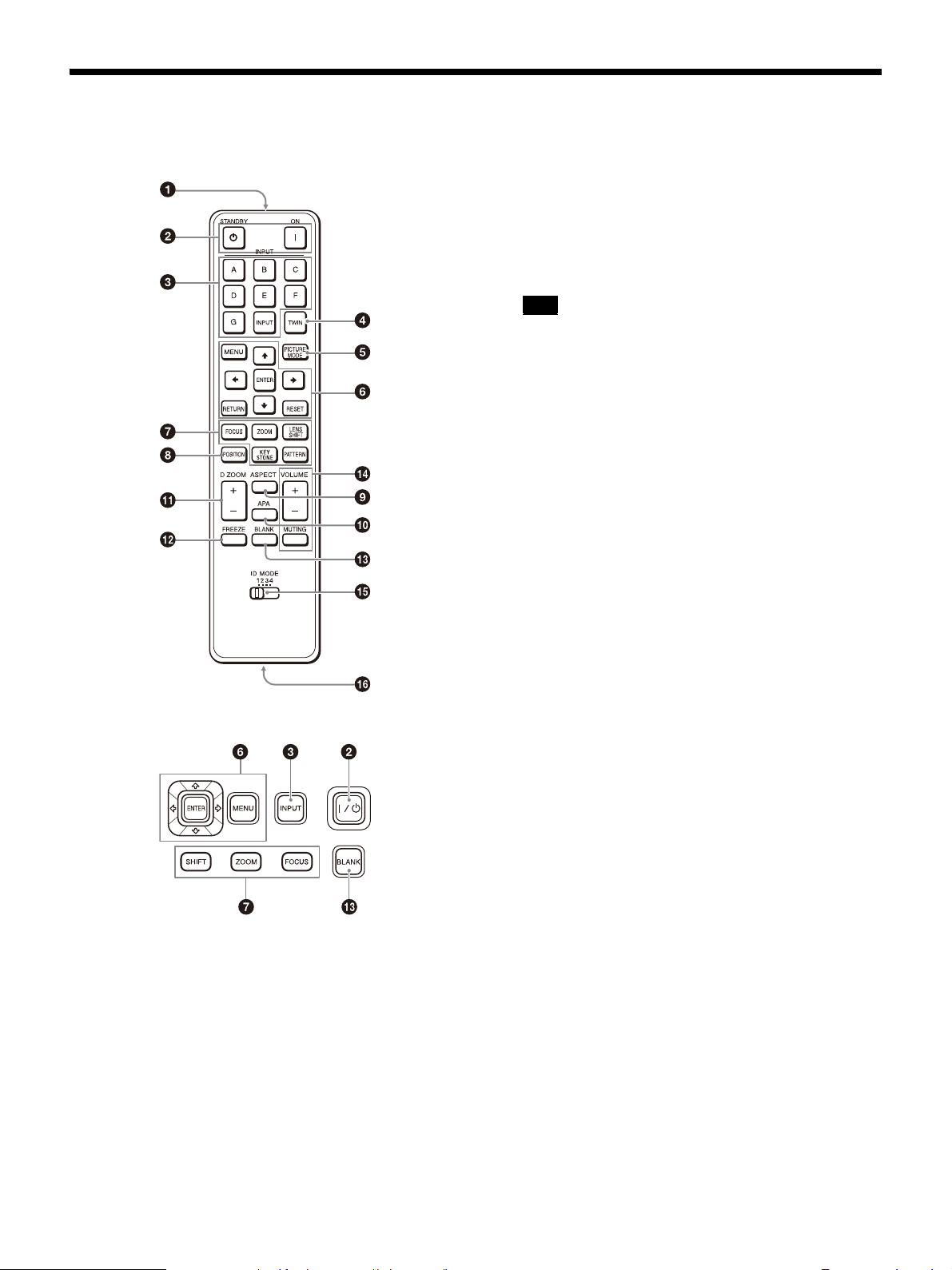
Remote Commander and Control Panel
Remote Commander
TWIN (Twin Picture) key
You can project the images from two input
signals on the screen as a main picture and
subpicture at the same time (page 22).
PICTURE MODE key
Changes the picture quality mode.
Note
When “Intelligent Setting” in the Projection Setting
menu is set to “On,” “Picture Mode” cannot be set
(page 24).
MENU key/ENTER key//// (arrow)
keys/RETURN key/RESET key
Operating a menu (page 23).
FOCUS key
Use this key when attaching the electric focus
lens (page 17).
ZOOM key
Use this key when attaching the electric zoom
lens (page 17).
LENS SHIFT/SHIFT key/PATTERN key/
KEYSTONE key
Use this key when adjusting the projected
image (page 17).
Control Panel
Infrared transmitter
(On) key/ (Standby) key
Turns on the projector or enters the standby
mode.
INPUT key
Selecting an input signal (page 16).
POSITION (Picture Position) key
You can store up to six combinations of lens
settings (focus, picture size (Zoom), picture
position (Lens shift)) (page 21).
ASPECT key
Changes the aspect ratio of the projected
image (page 28).
APA (Auto Pixel Alignment) key
Automatically adjusts a picture to its clearest
while a signal from a computer is input via the
RGB input terminal (INPUT A, INPUT B). You
can cancel the adjustment by pressing the
APA key again while adjusting.
D ZOOM (Digital Zoom) key
Enlarges a part of the image while projecting
(page 22).
FREEZE key
Pauses a projected image. Press again to
restore the image. Use this key when inputting
a computer signal.
6

BLANK key
Temporarily cuts off the image. Press again to
restore the image.
VOLUME key/ MUTING key
Not in use for the projector.
ID MODE switch (page 30)
Sets an ID mode of the Remote Commander. If
you assign a different ID number to each
projector when multiple projectors are used,
you can control only the projector with the
same ID mode as that of the Remote
Commander.
CONTROL S output terminal
Not in use for the projector.
About Remote Commander operation
Direct the Remote Commander toward the
remote control receiver.
The shorter the distance between the Remote
Commander and the projector is, the wider the
angle within which the Remote Commander can
control the projector becomes.
If there is any obstruction between the Remote
Commander and the remote control receiver on
the projector, the projector may not be able to
receive signals from the Remote Commander.
7
Connections and Preparations
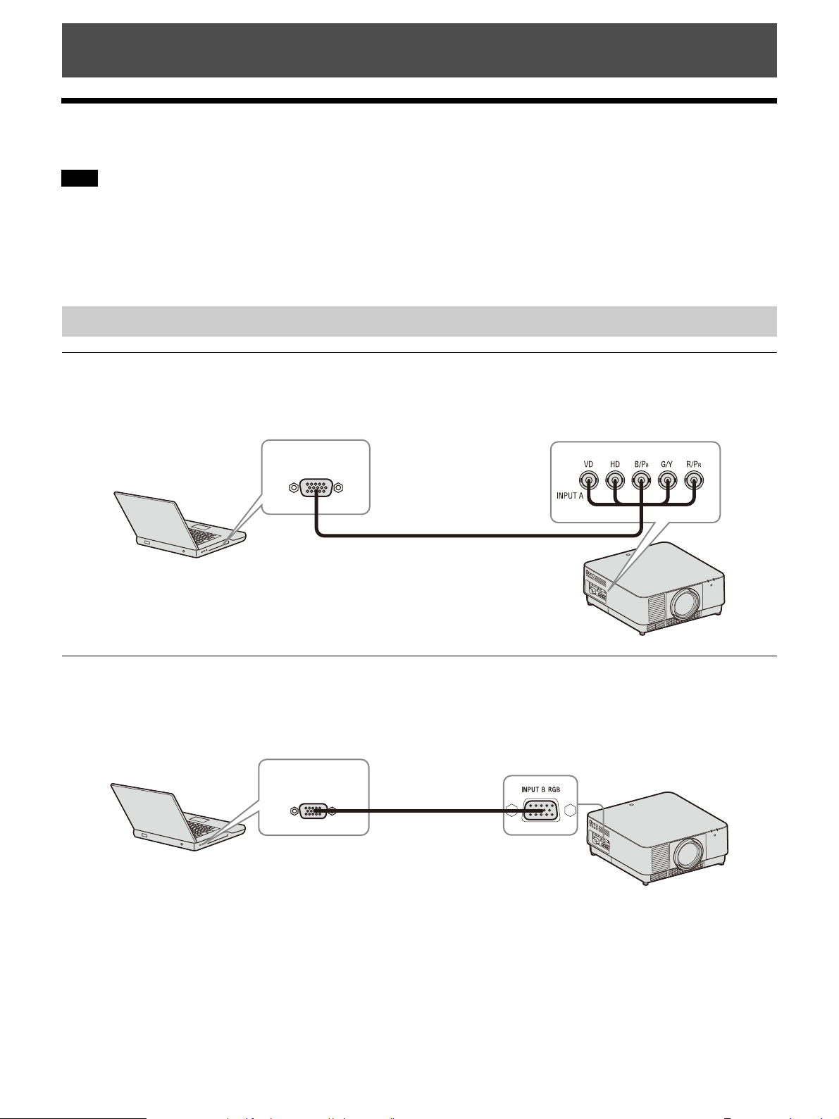
Computer
RGB output
terminal
Mini D-sub 15-pin - BNC cable (not supplied)
Computer
RGB output
terminal
Mini D-sub 15-pin cable
(not supplied)
Connecting the Projector
Notes
Turn off all devices before making any connections.
Use the proper cables for each connection.
Insert the cable plugs firmly; Loose connections may reduce performance of picture signals or cause a
malfunction. When unplugging a cable, be sure to grip the plug and not the cable itself.
For more information, also refer to the instruction manual of the device to be connected.
Connecting to a Computer
INPUT A
This terminal is used when connecting the projector to a computer over a long distance.
INPUT B
This terminal is used when connecting the projector to a computer with a RGB output terminal.
It is recommended that you set the resolution of your computer to 1920 × 1200 pixels for the external
monitor.
8
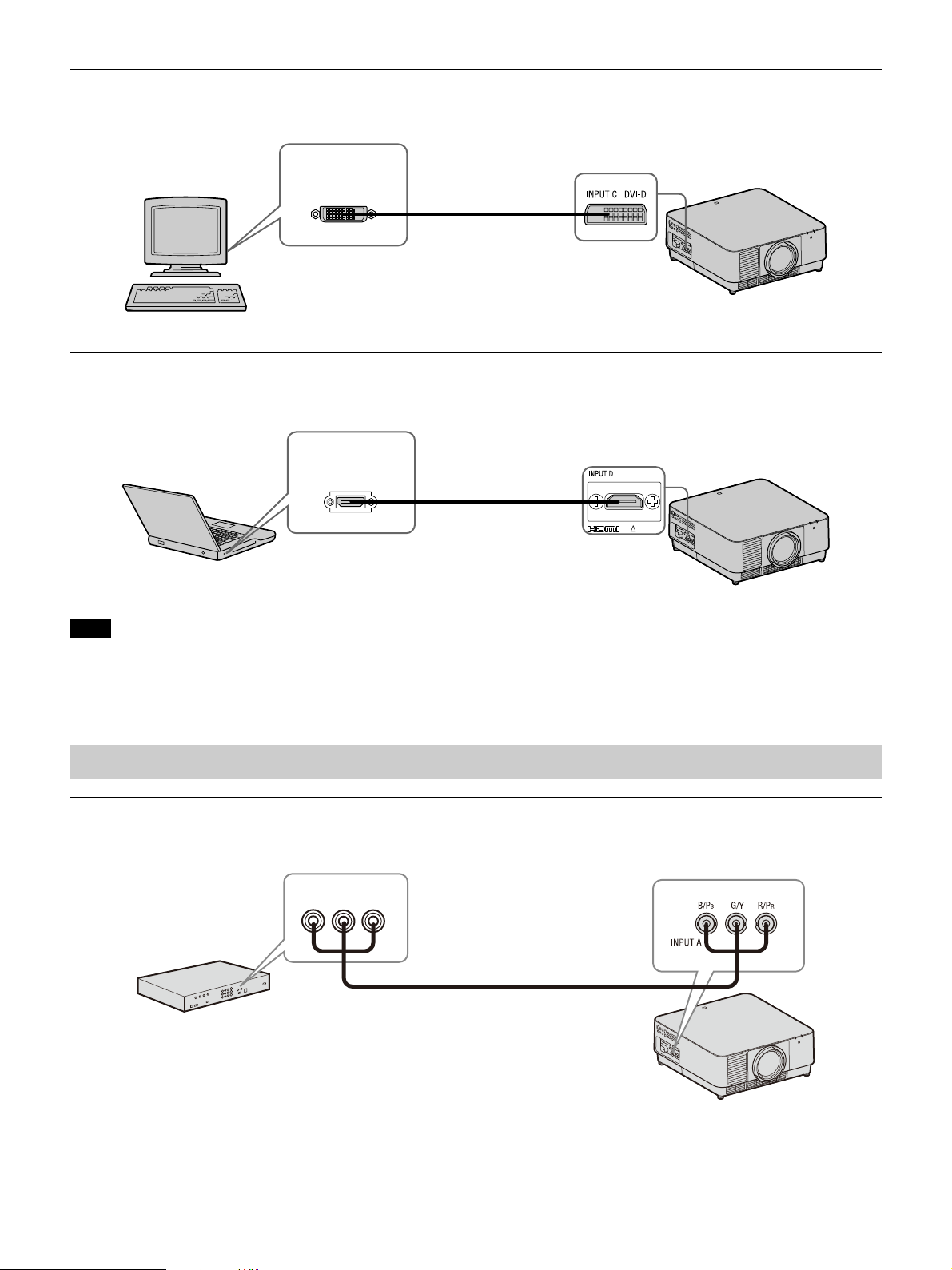
INPUT C
Computer
DVI-D output
terminal
DVI-D cable
(not supplied)
INPUT D
Computer
HDMI output
terminal
HDMI cable
(not supplied)
Video device
YP
BPR output
terminal
Component - BNC cable (not supplied)
This terminal is used when connecting the projector to a computer with a DVI-D output terminal.
INPUT D
This terminal is used when connecting the projector to a computer with a HDMI output terminal.
Notes
Use HDMI-compatible device which has the HDMI Logo.
Use a high speed HDMI cable(s) on which the cable type logo is specified. (Sony products are recommended.)
The HDMI terminal of this projector is not compatible with DSD (Direct Stream Digital) signal or CEC (Consumer Electronics
Control) signal.
Connecting to a Video Device
INPUT A
This terminal is used when connecting the projector to a video device over a long distance.
9
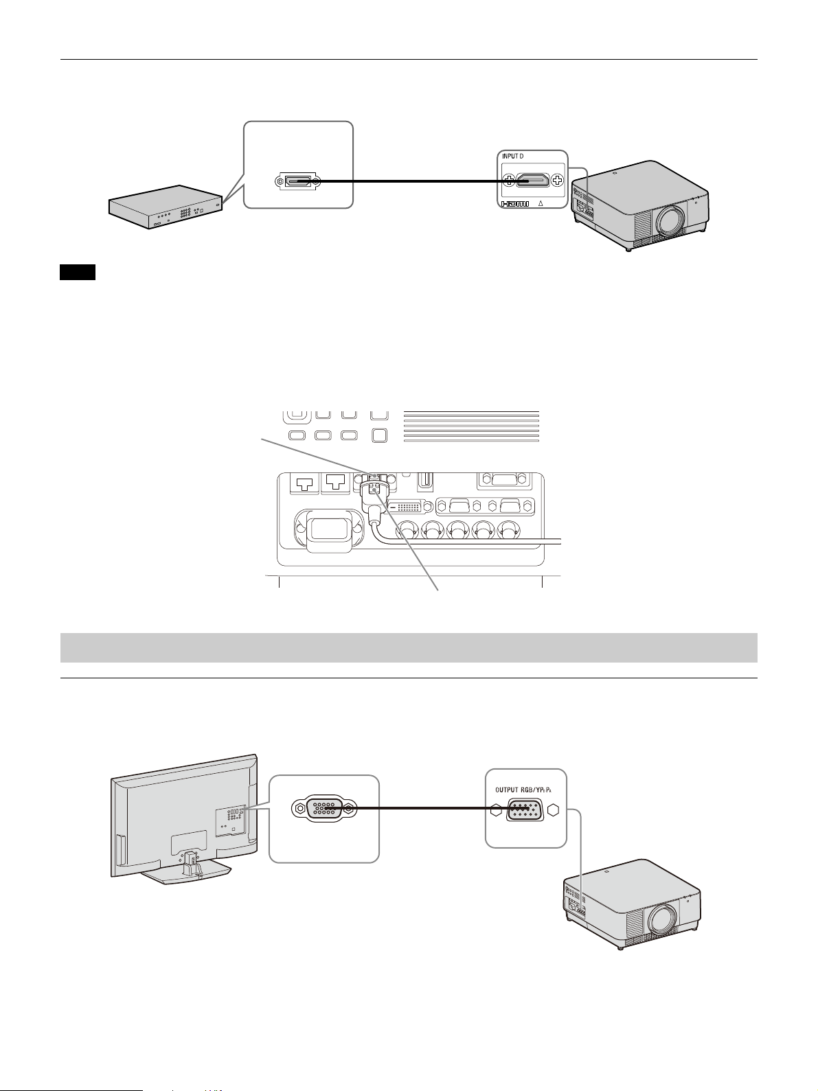
INPUT D
INPUT D
Video device
HDMI output
terminal
HDMI cable
(not supplied)
Screw hole
Cable bracket (not supplied)
Display device
RGB input
terminal
Mini D-sub 15pin cable
(not supplied)
This terminal is used when connecting the projector to a video device with a HDMI output terminal.
Notes
Use an HDMI cable with the HDMI logo.
The HDMI terminal of this projector is not compatible with DSD (Direct Stream Digital) signal or CEC (Consumer Electronics
Control) signal.
To fi x t he HDMI ca bl e
As shown in the following figure, fix the HDMI cable to the screw hole above the terminal using a
commercially available-cable bracket.
Connecting to an External Monitor
OUTPUT
This terminal outputs projected images. The images are output when a computer signal is input from the
RGB input terminal (INPUT A, INPUT B) or a video signal is input from the YP
10
BPR input terminal (INPUT A).
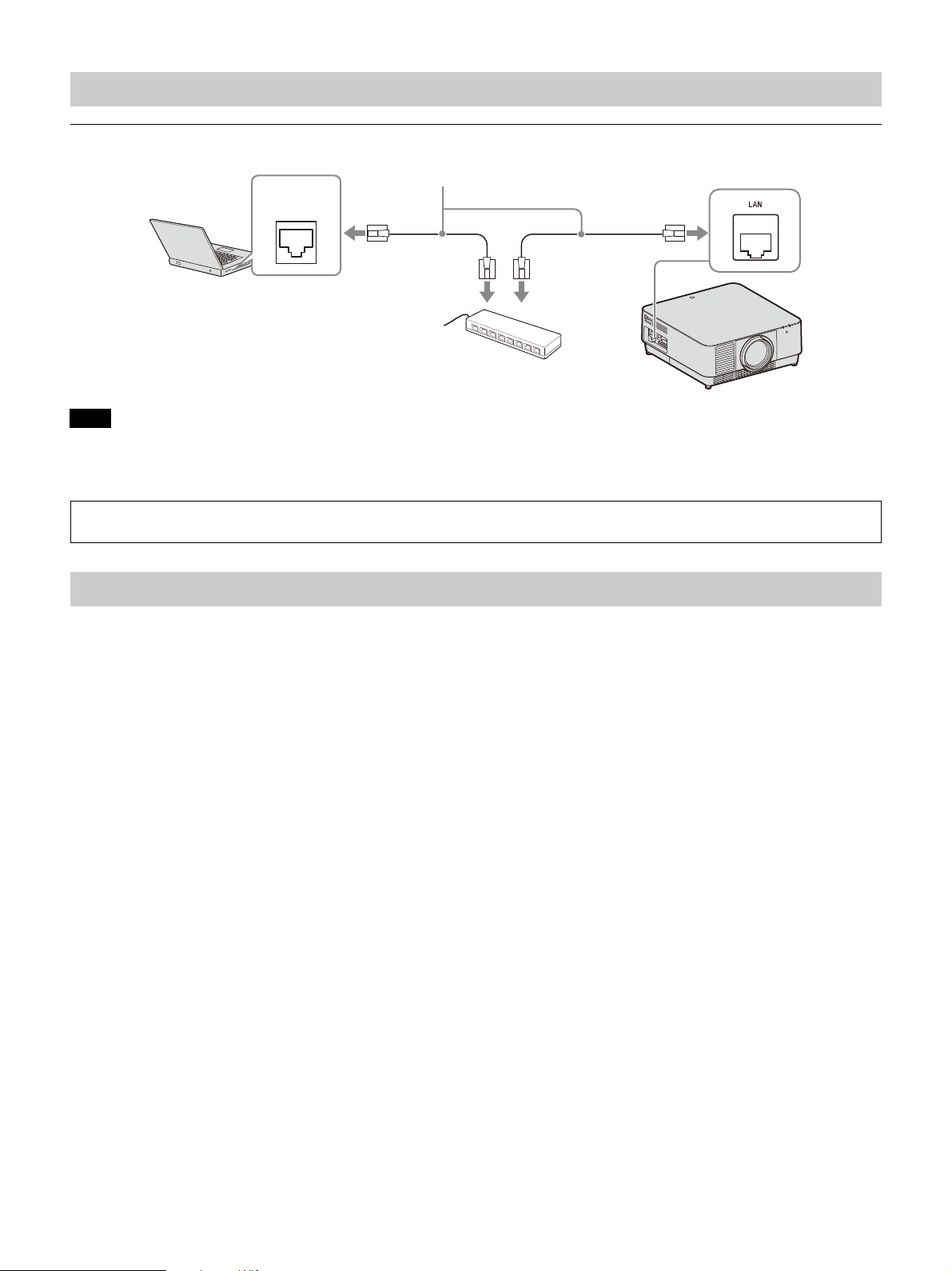
Connecting to a Network Equipment
LAN cable (straight type) (not supplied)
Computer
LAN
terminal
Hub, router, etc
When you monitor and control the projector via the network, access the Setup page of the projector (page 41) via a Web
browser and enable the desired control protocol.
Using a LAN terminal
Notes
When using network features via the LAN terminal, be sure to check if “LAN Setting” is set to “LAN Port” (page 31).
Connect the projector to the network that is constructed to control the access from the internet, such as LAN. If the
projector is connected directly to the internet, the security risk is increased.
Connecting to a HDBaseT™ Device
The HDBaseT transmitter is used when connecting the projector to a computer, video device, or network
equipment.
Notes for connecting this unit to the HDBaseT transmitter
Ask a professional or Sony dealer to perform wiring. If wiring has been insufficiently performed, it
affects the transmission characteristics of the cable, and causes broken or unstable images.
Connect the cable directly to the HDBaseT transmitter without going through a hub or router.
Use cables that meet the following conditions.
-CAT5e or higher
- Shielded type (covering connectors)
- Straight wire connection
-Single wire
When installing the cables, use a cable tester, cable analyzer, or similar device to check if the cables
meet the CAT5e or higher requirement. If there is a transit connector between this unit and the HDBaseT
transmitter, include it when measuring.
To reduce the affect of noise, install and use the cable in a manner where it is not rolled up and it is as
straight as possible.
Install the cable away from the other cables (especially the power cable).
When installing multiple cables, do not bind them and keep the running parallel distance as short as
possible.
The transmittable distance of the cable is 100 m (approx. 328 feet) maximum. If it exceeds 100 m
(approx. 328 feet), it may cause broken images or a malfunction in LAN communication. Do not use the
HDBaseT transmitter beyond the maximum transmittable distance of the cable.
For operation or function problems caused by devices of other manufacturers, contact the relevant
manufacturer.
11
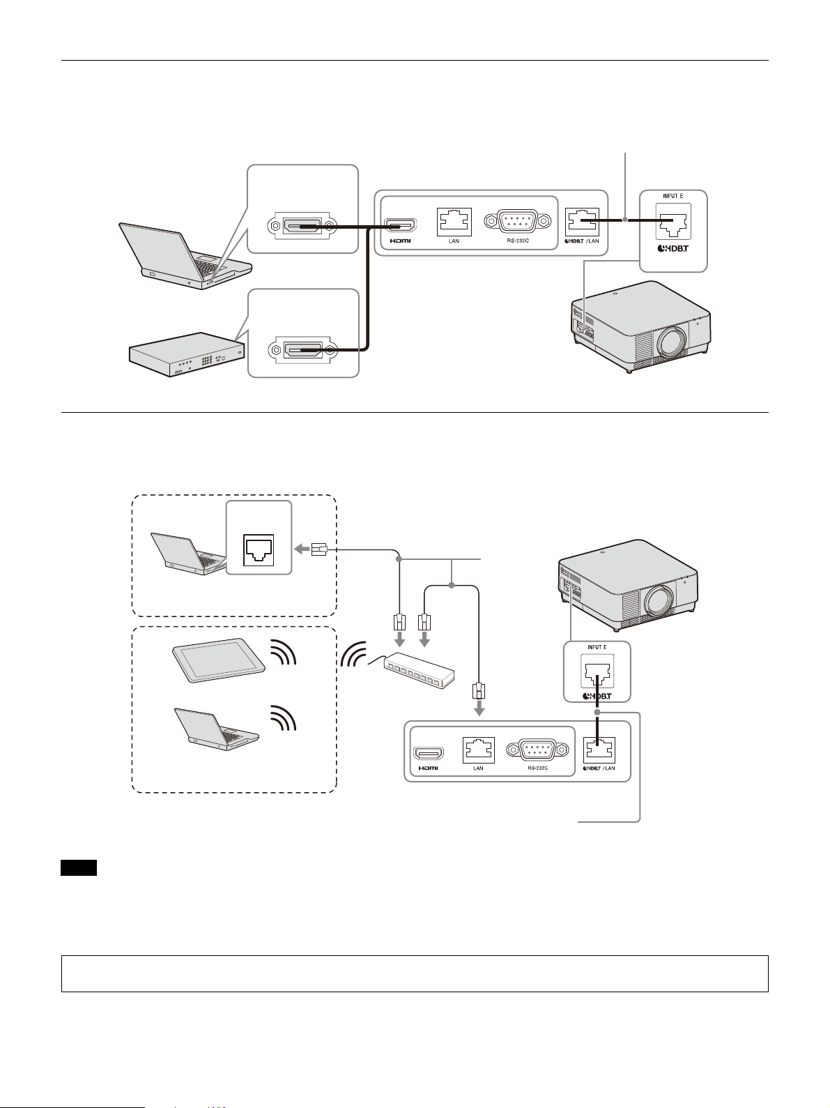
Connecting to a computer/video device
Computer
LAN cable: STP cable with CAT5e or
higher (straight type) (not supplied)
HDMI output
terminal
HDMI cable
(not supplied)
HDBaseT transmitter
HDMI output
terminal
Video device
LAN cable (straight type)
(not supplied)
Wired connection
Wireless connection
Computer
LAN
terminal
Tablet PC/Smartphone
Computer
Hub, wireless router
HDBaseT transmitter
LAN cable: STP cable with CAT5e or
higher (straight type) (not supplied)
When you monitor and control the projector via the network, access the Setup page of the projector (page 41) via a Web
browser and enable the desired control protocol.
INPUT E
Connecting to a network equipment (using an HDBaseT terminal)
The HDBaseT terminal is used when connecting the projector to a network equipment to control the
projector.
Notes
When using network features, be sure to check if “LAN Setting” is set to “via HDBaseT” (page 31).
Connect the projector directly to the HDBaseT transmitter without going through a hub or router.
Set “Extron XTP” in the Connection/Power menu to “On” when connecting to XTP Systems manufactured by Extron
Electronics (page 31).
12
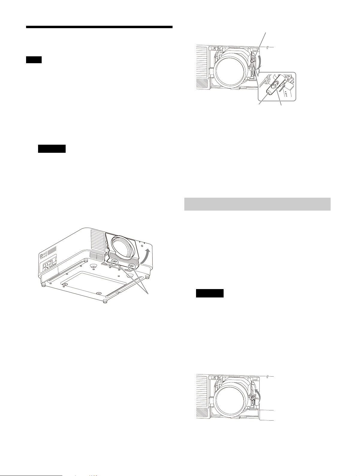
Attaching the Projection Lens
LENS COVER RELEASE
buttons
Lever
Lever
Slide switch
Notes
Avoid removing/attaching the lens with the projector
installed suspended from a ceiling.
For usable projection lenses, see “Optional accessories”
(page 54).
Do not attach any lens other than the specified accessory
lens sold separately.
Be careful not to drop the projection lens.
Avoid touching the lens surface.
1 Turn off the projector, then unplug the AC
power cord from the wall outlet.
Caution
When replacing the lens, your eyes may be
damaged if a strong light accidentally gets into
your eyes. Before replacing the lens, turn off the
projector and then unplug the AC power cord.
2 Remove the lens cover.
While sliding the LENS COVER RELEASE
buttons inward, pull out the lens cover until it
clicks into place.
5 Attach the lens cover.
Hang the upper side of the lens cover on the
top cover of the projector and press it until it
clicks into place. Then, while sliding the LENS
COVER RELEASE buttons inward, insert the
lens cover.
Even when the lens is attached, you can attach/
remove the lens cover in the same way.
Removing the Projection Lens
1 Return the projection lens to the center
position.
While the projector is turned on, press the
LENS SHIFT key on the Remote Commander,
then press the RESET key on it. The projection
lens returns to the center position.
3 Turn the contact substrate to the left facing
the front of the lens and insert the lens to the
end.
4 While pressing the slide switch, lower the
lever until it clicks into place.
2 Turn off the projector, then unplug the AC
power cord from the wall outlet.
Caution
When replacing the lens, your eyes may be
damaged if a strong light accidentally gets into
your eyes. Before replacing the lens, turn off the
projector and then unplug the AC power cord.
3 Remove the lens cover.
4 While pressing the slide switch, move the
lever up to the limit, and pull the lens straight
out.
5 Attach the lens cover.
13
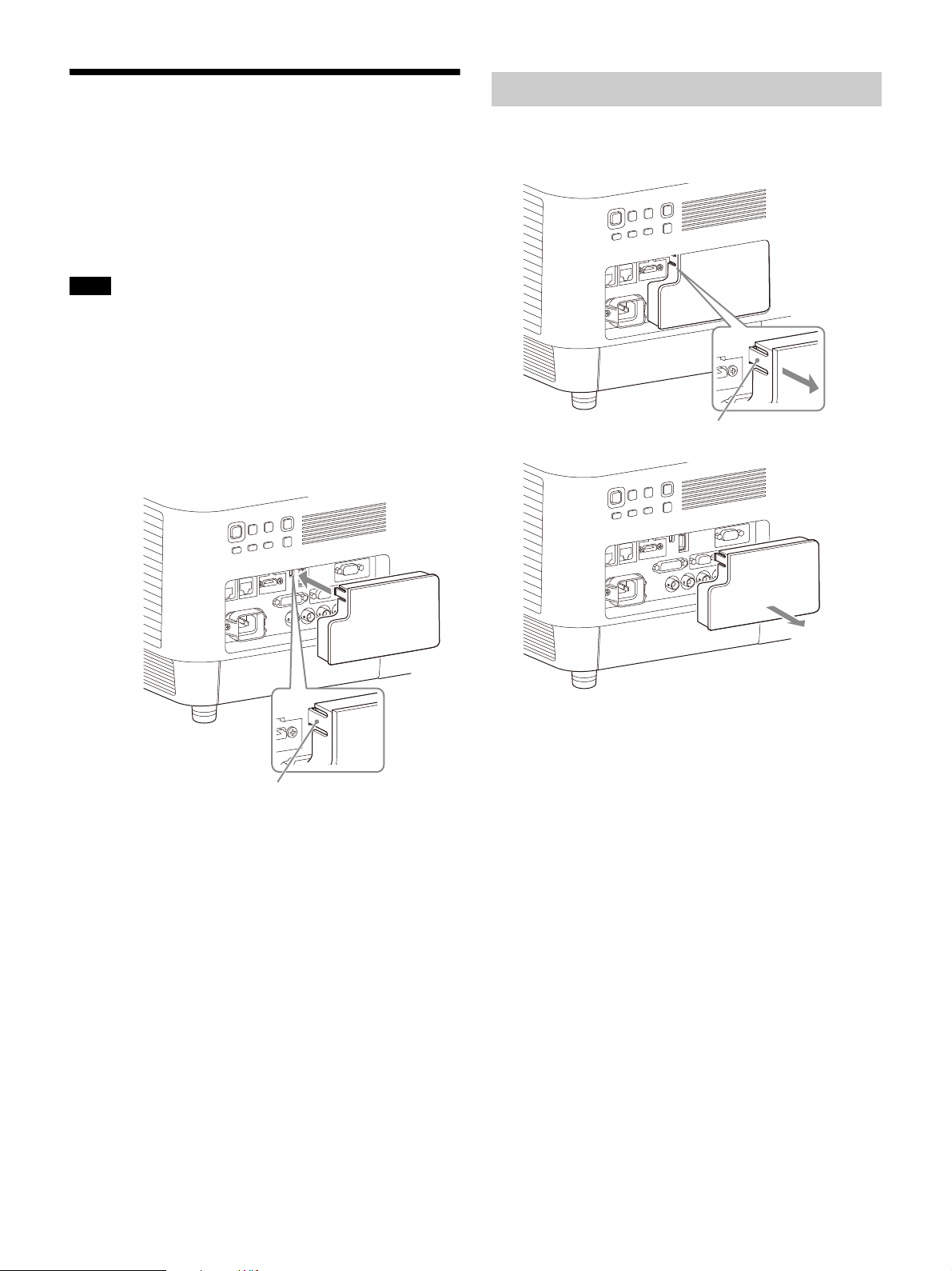
Attaching the Terminal Cover
Ta b
Tab
You can attach the supplied terminal cover when
the LAN terminal, INPUT D (HDMI), or INPUT E
(HDBaseT) is limited to use for connection.
Attaching the supplied terminal cover prevents
dust from entering the terminals and maintains a
neat appearance.
Note
The terminal cover may not be attached depending on the
condition of the connected cables or installation methods,
such as directly placing the unit on the floor. However, this
has no impact on normal use.
1 Insert the tab of the terminal cover into the
slot and attach the terminal cover.
Make sure that the tab of the terminal cover is
firmly inserted.
Removing the Terminal Cover
1 Pull out the terminal cover while pressing the
tab.
14
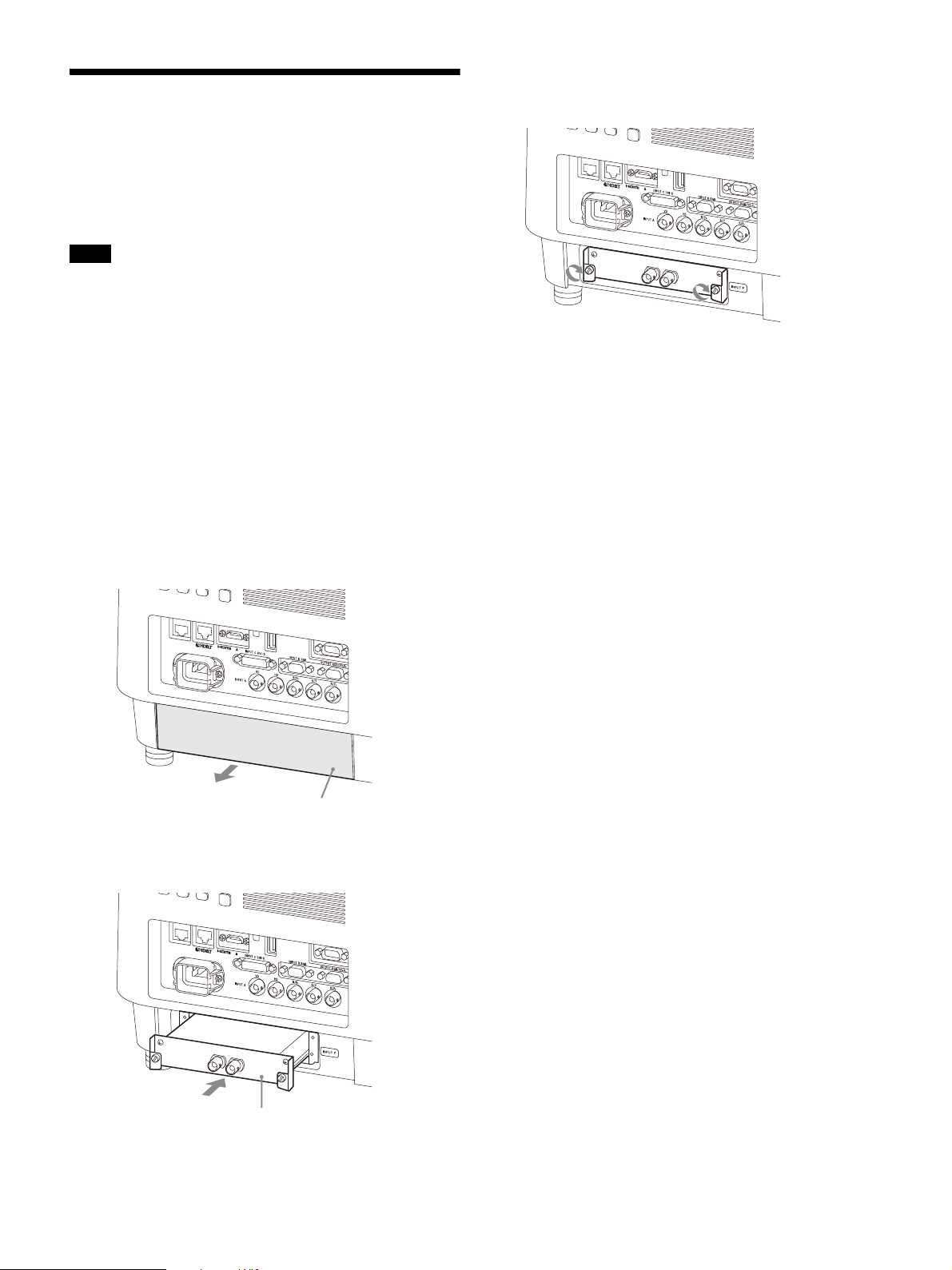
Installing the Optional
Optional slot
cover
Example: 3G-SDI INPUT Adaptor
(not supplied)
Adaptor
When installing an optional adaptor (not supplied) into the
optional adaptor slot on the terminals of the projector, you
can use the optional adaptor as INPUT F.
Notes
Be sure to retain the optional slot cover removed when
installing the optional adaptor. When removing the
optional adaptor, attach the cover.
For details on available optional adaptors, see “Optional
accessories” (page 54).
Do not install optional adaptors other than the one
specified as the optional accessory.
For details on how to use, also refer to the operating
instructions of the optional adaptor.
1 Turn off the projector, then unplug the AC
power cord from the wall outlet.
2 To remove the optional slot cover attached to
the terminals, press the lower part of the
optional slot cover.
4 Tighten the two screws on the optional
adaptor.
3 Insert the optional adaptor as far as it goes.
15

Projecting/Adjusting an Image
Projecting an Image
The size of a projected image depends on the
attached lens or the distance between the
projector and screen. Place the projector so that
the projected image fits the screen size. For details
on projection distances and projected image sizes,
see “Projection Distance and Lens Shift Range”
(page 58).
1 Plug the AC power cord into a wall outlet.
2 Connect all necessary devices to the projector
(page 8).
3 Turn on the projector.
Press the / key on the main unit or the key
on the Remote Commander.
4 Turn on the connected device.
5 Select the input source.
Press the INPUT key on the projector or on the
Remote Commander to display the input
select window. Press the INPUT key repeatedly
or the / key to select an image to be
projected. The signal icon appears on the
right side in the input select window when a
signal is input.
Also, you can select an input signal on the
Remote Commander.
*1: When INPUT F is input with the compatible
optional adaptor attached, the signal icon
always appears.
*1
Turning Off the Power
1 Press the / key on the main unit or the
key on the Remote Commander.
The shutdown process is started and the
projector enters the standby mode.
For long-term use, turn off the projector when
not in use.
2 Unplug the AC power cord from the wall
outlet.
6 Change the computer screen output
destination to an external display.
How to change the output destination varies
depending on the type of computer.
(Example)
7 Adjust the projected image (page 17).
16
Adjusting the Projected Image
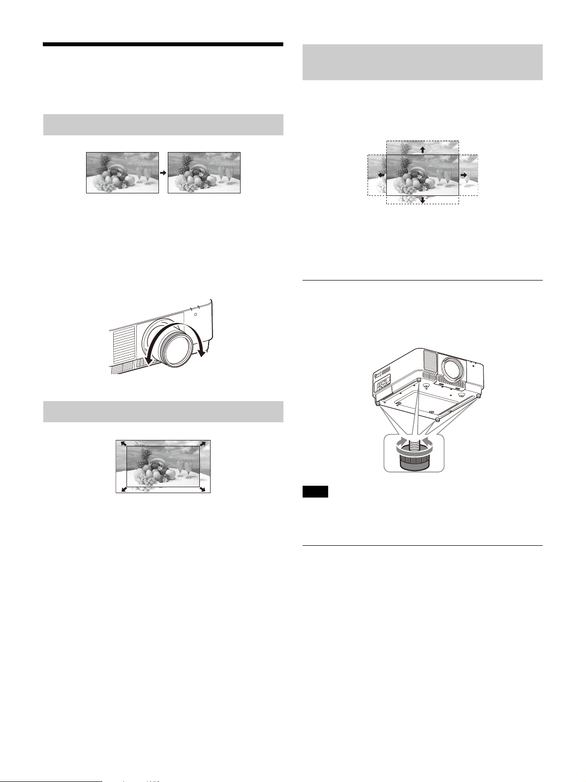
Focusing the image (Focus)
When attaching the Electric focus lens
Press the FOCUS key on the projector or the
Remote Commander then press the /// key.
When attaching the Manual focus lens
Turn the focus ring.
Adjusting the position of the image (Lens shift)
Press the LENS SHIFT/SHIFT key on the projector or
the Remote Commander then press the ///
key.
To return the lens to the center position of the
projected image
Press the RESET key on the Remote Commander
while adjusting the position of the image.
Adjusting the tilt of the projector with the
adjustable feet
When the projector is placed on an uneven
surface, adjust it using the adjustable feet.
Adjusting the image size (Zoom)
When attaching the Electric zoom lens
Press the ZOOM key on the projector or the
Remote Commander then press the /// key.
Notes
Be careful not to pinch your fingers.
Do not push hard on the top of the projector with the
adjustable feet extended. It may cause a malfunction.
Displaying a pattern for adjusting an image
You can display a pattern for adjusting the
projected image with the PATTERN key on the
Remote Commander. Use / to change the
pattern and / to change its color. Press the
PATTERN key again to restore the previous image.
17
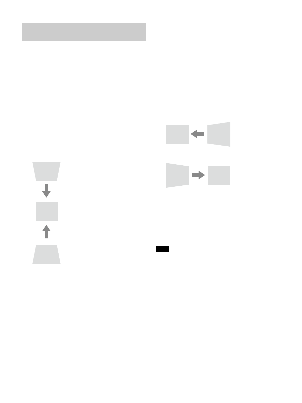
Correcting for Trapezoidal Distortion of the
Increase setting
Decrease setting
Increase the setting
Decrease setting
Projected Image (Keystone Adjustment)
If the projected image is trapezoidally-distorted in
the lateral plane
If the screen is tilted, or you are projecting from an
oblique angle, perform keystone adjustment.
If the projected image is trapezoidally-distorted in
the vertical plane
1 Press the KEYSTONE key on the Remote
Commander once or select “Screen Fitting” in
the Installation menu (page 33).
2 Select “V Keystone.”
3 Adjust the value using /.
The higher the setting, the narrower the top of
the projected image. The lower the setting,
the narrower the bottom of the projected
image.
1 Press the KEYSTONE key on the Remote
Commander once or select “Screen Fitting” in
the Installation menu (page 33).
2 Select “H Keystone.”
3 Adjust the value using /.
The higher the setting, the narrower the right
side of the projected image. The lower the
setting, the narrower the left side of the
projected image.
Press the RESET key to restore the projected
image before adjustment.
*1
Press the RESET key to restore the projected
image before adjustment.
*1: The setting may not be reset depending on the
combination of adjustment values of the Screen Fitting
setting items. In this case, reset all of the Screen Fitting
setting items.
Notes
Keystone adjustment is an electronic correction.
Consequently the image quality may deteriorate.
Depending on the position adjusted with the lens shift
feature, performing keystone adjustment may change
the aspect ratio of the original image, or the projected
image may be distorted.
*1
18
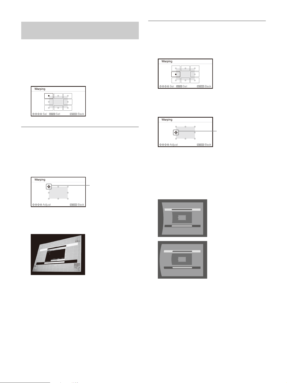
Correcting Image Twist (Warp Correction
Adjust using this cursor
Adjust using this cursor
Feature)
When correcting deflection on the left/right side
of the image
1 Press the KEYSTONE key on the Remote
Commander once or select “Screen Fitting” in
the Installation menu (page 33).
2 Select “Warping.”
The guide is displayed.
When correcting the corner(s) of the image
1 Move using /// to select the corner
you want to correct.
2 Press the ENTER key.
The cursor appears.
1 Move using /// to select the side you
want to correct.
2 Press the ENTER key.
The cursor appears.
3 Adjust the deflection of the side, using //
/.
You can adjust the center point of deflection
using /. For the range of deflection, use /
. You can separately adjust the left/right
side.
3 Adjust the position of the corner you want to
correct, using ///.
Press the RESET key to restore the projected
image before adjustment.
*1
Press the RESET key to restore the projected
image before adjustment.
*1
19
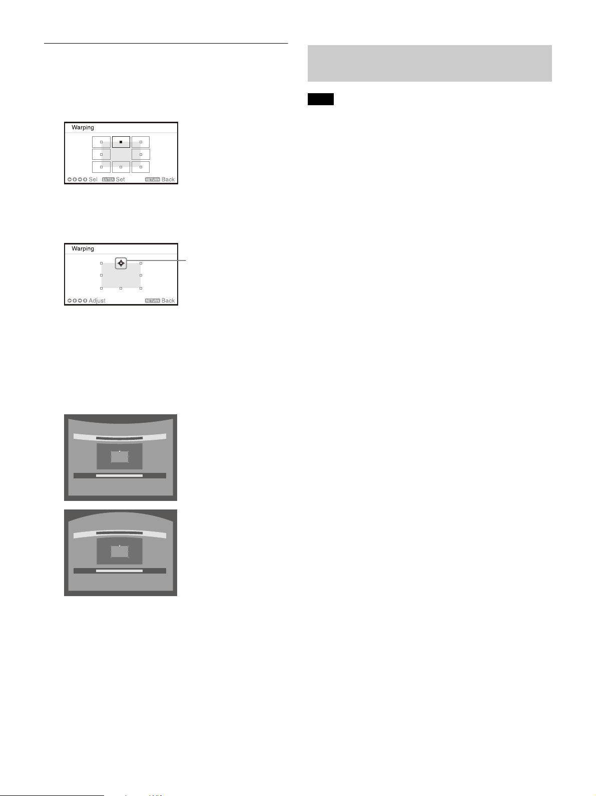
When correcting deflection on the top/bottom
Adjust using this cursor
side of the image
Blending Projections from Multiple Projectors on a Screen
1 Move using /// to select the side you
want to correct.
2 Press the ENTER key.
The cursor appears.
3 Adjust the deflection of the side, using //
/.
You can adjust the center point of deflection
using /. For the range of deflection, use /
. You can separately adjust the top/bottom
side.
Notes
Depending on the blending start position or the
blending width, the menu may overlap with the blending
area and become invisible. If you want to operate the
projector while viewing the menu, set “Edge Blending” to
“Off” once and make adjustments. Then, set “Edge
Blending” to “On.”
The procedure shown above is for general guidance. You
may adjust the settings to the situation.
When multiple projectors are set up in a line, the
temperature inside the projectors may increase due to
exhaust vent proximity, and an error indication may
result.
In this case, space the projectors farther apart and/or
install deflection partitioning between them.
For more details, consult with qualified Sony personnel.
1 Place the projectors.
Input a pattern, etc., to adjust the projected
positions from multiple projectors.
2 Set the ID mode.
Set a different ID mode for each projector
(page 30).
3 Set the picture mode.
Set “Picture Mode” of the multiple projectors
to “Multi Screen” (page 24).
Press the RESET key to restore the projected
image before adjustment.
*1: The setting may not be reset depending on the
combination of adjustment values of the Screen Fitting
setting items. In this case, reset all of the Screen Fitting
setting items.
*1
4 Unify the color space.
Set the color space of the multiple projectors
to the same mode (Custom 1 to 3) (page 25).
R/G/B can be finely adjusted as necessary.
5 Adjust the color matching setting.
Finely adjust each tone as necessary
(page 33).
6 Set the Edge Blending setting.
When overlaying multiple projections, the
Edge Blending setting is available.
Select “Multi Screen” in the Installation menu,
then select “Edge Blending” (page 33).
7 Enable the Edge Blending function.
In “Blend Settings” of the Installation menu,
set “Edge Blending” to “On” for each blending
position (page 33).
20
 Loading...