

Data
Projector
4-191-106-17 (1)
Operating Instructions
Before operating the unit, please read this manual and supplied Quick Reference Manual
thoroughly and retain it for future reference.
VPL-FH500L/FH500
VPL-FX500L/FX500
Not all models are available in all countries and area. Please check
with your local Sony Authorized Dealer.
© 2010 Sony Corporation

Table of Contents
Overview
Location and Function of Controls .... 3
Main Unit .....................................3
Terminals ...................................... 4
Remote Commander and Control
Panel ..........................................5
Preparation
Connecting the Projector ................... 8
Connecting a Computer ................8
Connecting a Video Equipment ... 9
Connecting an External
Monitor ................................... 11
Projecting/Adjusting an
Image
Projecting an Image ......................... 12
Adjusting the Focus, Size, and
Position of the Projected
image ....................................... 13
Turning Off the Power ................14
Adjustments and Settings
Using a Menu
Using a MENU ................................ 15
The Picture Menu .............................16
The Screen Menu .............................18
The Function Menu .......................... 22
The Operation Menu ........................ 23
The Connection/Power Menu .......... 25
The Installation Menu ...................... 26
The Information Menu .....................28
Network
Using Network Features ...................29
Displaying the Control Window of
the Projector with a Web
Browser ...................................29
Confirming the Information
regarding the Projector ............30
Operating the Projector from a
Computer .................................30
Using the Mail Report
Function ...................................30
Others
Indicators ..........................................32
Messages List ...................................33
Troubleshooting ................................34
Replacing the Lamp ..........................36
Replacing the Air Filter
Cartridges ......................................38
Attaching/Removing the Projection
Lens ...............................................40
Attaching .....................................40
Removing ....................................47
Installing the Optional Adapter ........47
Specifications ...................................48
Projection Distance and Lens Shift
Range ............................................56
Dimensions .......................................63
Index .................................................66
2
Table of Contents

B Overview
q
Location and Function of Controls
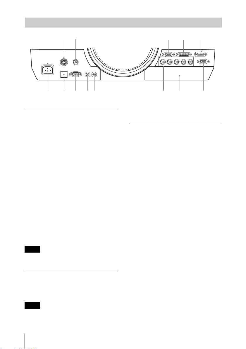
Main Unit
69qs3
qf
a Lens (not supplied) (page 40)
b Front panel (page 40)
c Lamp cover (page 36)
d Air filter cover (page 38)
e Ventilation holes (intake)
f Ventilation holes (exhaust)
Caution
Do not place anything near the ventilation
holes as this may cause internal heat
buildup. Do not place your hand near the
ventilation holes and the circumference as
this may cause injury.
g ON/STANDBY indicator
(page 32)
h LAMP/COVER indicator
(page 32)
712
8
q;
qa
qg
4
qs
d
5
j Terminals (page 4)
k Optional adapter slot (page 47)
Install an optional adapter (not
supplied). (VPL-FH500L only)
l Remote control receiver
The remote control receivers are located
at the front and rear of the projector.
m Rear feet (adjustable) (page 14)
n Antitheft lock
Connects to an optional antitheft cable
manufactured by Kensington.
For details, visit Kensington’s web site.
http://www.kensington.com/
o Antitheft bar
Connects to a commercially available
antitheft chain or wire.
Overview
i Control panel (page 5)
Location and Function of Controls
3
Terminals
q
q;9q
18
6
7
23
4
S VIDEO IN
VIDEO IN
RS-232C
CONTROL S
IN OUT
PLUG INPOWER
a5qs
LAN
d
Input (page 8)
a INPUT A
Video: RGB/YPBPR input terminal
(RGB HD VD/YP
BPR)
b INPUT B
Video: RGB input terminal (RGB)
c INPUT C
Video: DVI-D input terminal (DVI-D)
d INPUT D (VPL-FH500L only)
Video: HDMI input terminal
e INPUT E (VPL-FH500L only)
Video: Optional adapter slot*
f S VIDEO (S VIDEO IN)
Video: S video input terminal
g VIDEO (VIDEO IN)
Video: Video input terminal
Note
* Regarding attachable optional adapter,
consult with qualified Sony personnel.
INPUT B RGB INPUT C DVI-D
R/PRG/Y HD VD
INPUT A
INPUT E
signal input from the YP
B/P
INPUT D HDMI
B
BPR input terminal
OUTPUT
MONITOR
(INPUT A).
Others
i RS-232C terminal
RS-232C compatible control terminal
j LAN terminal (page 29)
k CONTROL S input terminal (DC
power supply) (CONTROL S IN
PLUG IN POWER)
Connects to the CONTROL S output
terminal on the supplied Remote
Commander with a connecting cable
(stereo mini plug (not supplied)) when
using it as a wired Remote Commander.
You do not need to install batteries in the
Remote Commander, as the power is
supplied from this terminal.
l CONTROL S output terminal
(CONTROL S OUT)
For coupling control of multiple
projectors with the wired Remote
Commander.
Output (page 11)
h OUTPUT
Video: Monitor output terminal
(MONITOR)
Note
This terminal outputs the image. Output as a
computer signal input from the RGB input
terminal (INPUT A, INPUT B) or a video
4
Location and Function of Controls
m AC IN (∼) socket
Connects the supplied AC power cord.
Remote Commander and Control Panel
9
46
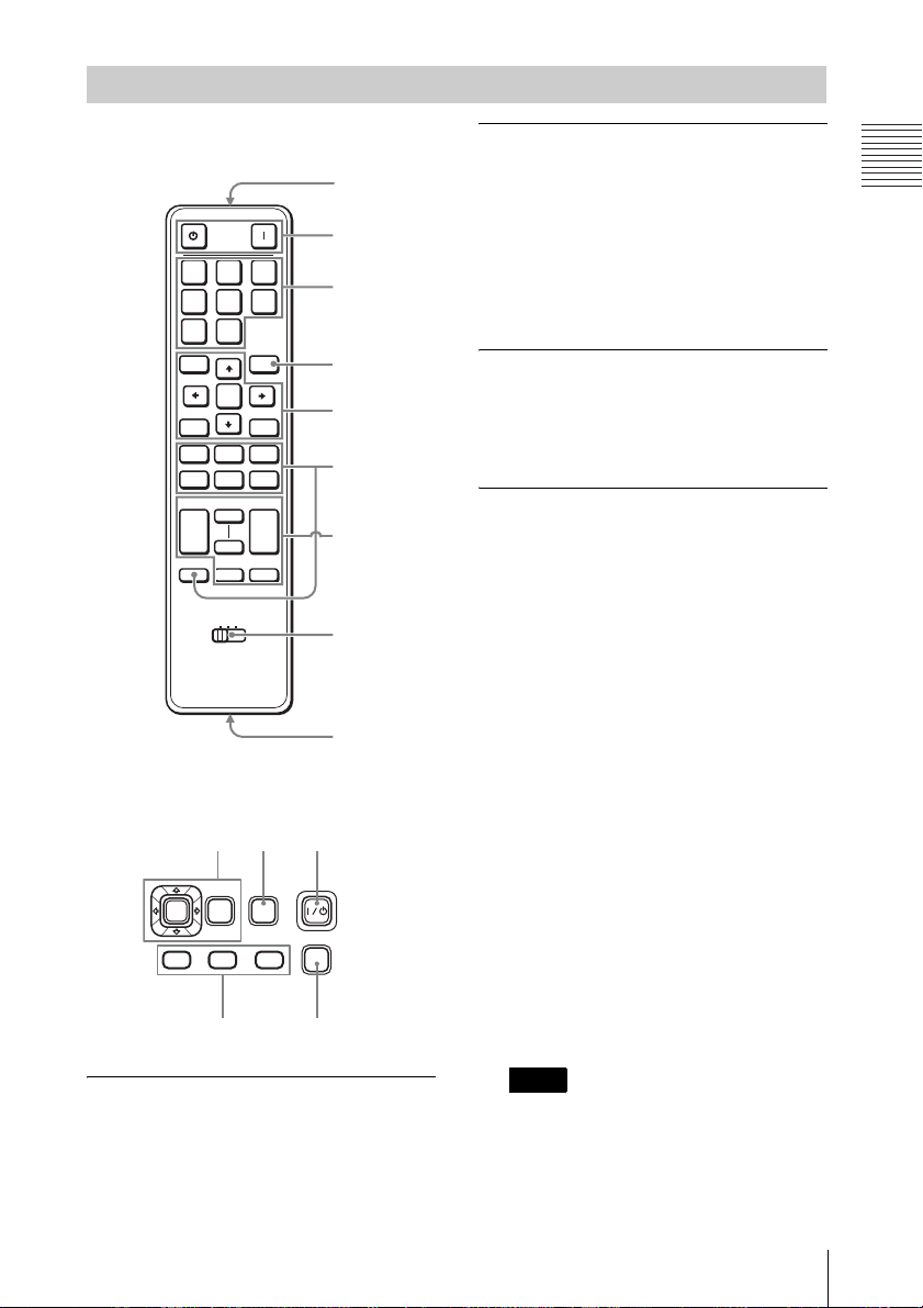
Remote Commander
7
ONSTANDBY
INPUT
ABC
DEF
S
VIDEO
VIDEO
MENU
ASPECT PATTERN
D ZOOM VOLUME
ECO
MODE
ENTER
RESETRETURN
SHIFTZOOMFOCUS
KEY-
STONE
MUTING
PIC
+
–
AUDIO
TWIN FREEZEAPA
ID MODE
1 2 3
+
–
1
2
6
3
4
5
8
Control Panel
312
ENTER
MENU
INPUT
SHIFT ZOOM
FOCUS
MODE
ECO
a Turning on the power/Going to
standby
? (On) key
1 (Standby) key
b Selecting an input signal
(page 12)
INPUT key (main unit)
Direct input select keys (Remote
Commander)
VPL-FH500L: The F key is not provided
in this projector.
VPL-FX500L: The D, E, and F keys are
not provided in this projector.
c Operating a menu (page 15)
ENTER /V/v/B/b (arrow) keys
MENU key
RETURN key
RESET key
d Adjusting the image (page 13)
FOCUS key
Use this key when attaching the power
focus lens.
ZOOM key
Use this key when attaching the power
zoom lens.
SHIFT key
ASPECT key (pages 18, 20)
Changes the aspect ratio of the projected
image.
KEYSTONE key
Adjusts the vertical trapezoidal
distortion of the image manually. When
you press this key, the Keystone menu is
displayed. Use the arrow keys (V/v/B/
b) for adjustment.
PATTERN key (page 14)
APA (Auto Pixel Alignment) key
Automatically adjusts a picture to its
clearest while a signal is input from a
computer. You can cancel the adjustment
by pressing the APA key again while
adjusting.
Note
*
Use this key when inputing a computer
signal via the RGB input terminal
(INPUT A, INPUT B).
Overview
*
Location and Function of Controls
5
e Using various functions during
projecting
D ZOOM (Digital Zoom) +/– key
*1
Enlarges a portion of the image while
projecting.
1 Press the D ZOOM + key to display
the digital zoom icon on the projected
image.
2 Press the V/v/B/b keys to move the
digital zoom icon to the point on the
image you wish to enlarge.
3 Press the D ZOOM + key or the D
ZOOM – key repeatedly to change the
enlargement ratio. The image can be
enlarged up to 4 times.
Press the RESET key to restore the
previous image.
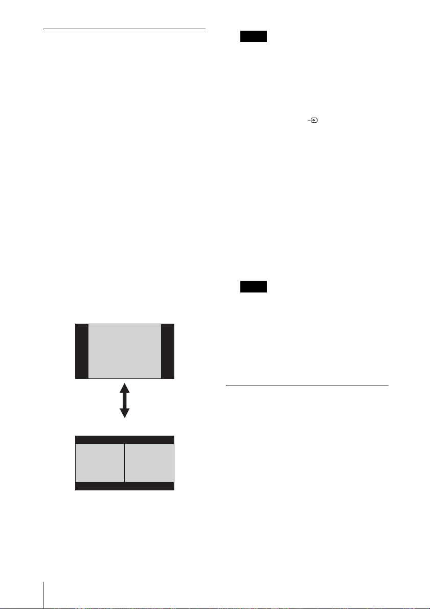
TWIN (Twin Picture) key
(VPL-FH500L only)
You can project the images from two
input signals on the screen as a main
picture and subpicture at the same time.
To switch between one and two pictures,
press the TWIN key on the Remote
Commander.
One picture display
Notes
• When displaying a two pictures, the ?
(On) key, 1 (standby) key, INPUT key,
and MUTING (PIC) key are available.
• When “Screen Aspect” (page 26) is set
to “4:3,” the two picture function is not
available.
• When displaying a two pictures, the
input signal icon does not appear in
the input select window (page 12).
• Picture settings set for one pictures may
not be reflected as two pictures.
MUTING key
PIC: Cuts off the image. Press again to
restore the image.
AUDIO: This function is not provided
in this projector.
VOLUME +/– key
This function is not provided in this
projector.
FREEZE key
*2
Pauses a projected image. Press again to
restore the image.
Notes
*1: Use this key when inputting a
computer signal. But it may not be
enabled, depending on the resolution
of the input signal and when
displaying a two pictures (VPLFH500L only).
*2: Use this key when inputting a
computer signal.
TWIN key
Two pictures display
(A) Main picture (B) Subpicture
You can select the image to project to the
main picture.
The subpicture is preset to display the image
from INPUT B.
For details on combinations of input signals,
see “Combinations of Input Signals” on
page 55.
6
Location and Function of Controls
f Setting the energy–saving mode
easily
ECO MODE key
“Lamp Mode,” “Power Saving Mode,”
and “Standby Mode” for energy-saving
can be set easily.
1 Press the ECO MODE key to display
the ECO Mode menu.
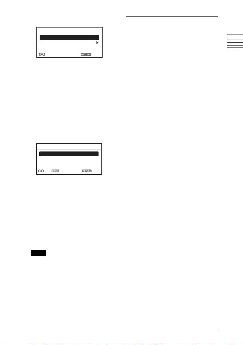
ECO Mode Menu
ECO Mode
ECO
User
Sel Back
2 Press the V/v key or ECO MODE key
to select ECO or User mode.
ECO: Sets each mode to the optimum
energy-saving value.
Lamp Mode: Standard
Power Saving Mode: Standby
Standby Mode: Low
(go to step 6)
User: Sets each item of the energy-
saving mode menu as you desire
(go to step 3).
3 Select “User” then press the b key.
The setting items appear.
Others
g Infrared transmitter
h ID MODE 1/2/3 switch (page 23)
Sets an ID mode of the Remote
Commander. If you assign a different ID
number to each projector when multiple
projectors are used, you can control only
the projector with the same ID mode as
that of the Remote Commander.
i CONTROL S output terminal
Connects to the CONTROL S input
terminal on the projector with a
connecting cable (stereo mini plug (not
supplied)) when using the Remote
Commander as a wired one.
You do not need to install batteries in the
Remote Commander, as the power is
supplied from the projector.
Overview
User
Lamp Mode Standard
Power Saving Mode Off
Standby Mode Standard
Set
Sel Back
4 Press the V/v key to select the ECO
Mode item then press the b key or the
ENTER key.
5 Press the V/v key to select the setting
value.
6 Press the RETURN key to restore the
previous image.
For details on ECO Mode settings, see
“Lamp Mode” (page 22) on the Function
menu and “Standby Mode” (page 25)
and “Power Saving Mode” (page 25) on
the Connection/Power menu.
Note
If you set “ECO Mode” to “ECO,” or
“Standby Mode” (in “User”) to “Low,”
the network control function will be
disabled in standby mode. If the external
control is being performed by using the
network or network control function, do
not select “ECO,” or do not set “Standby
Mode” (in “User”) to “Low.”
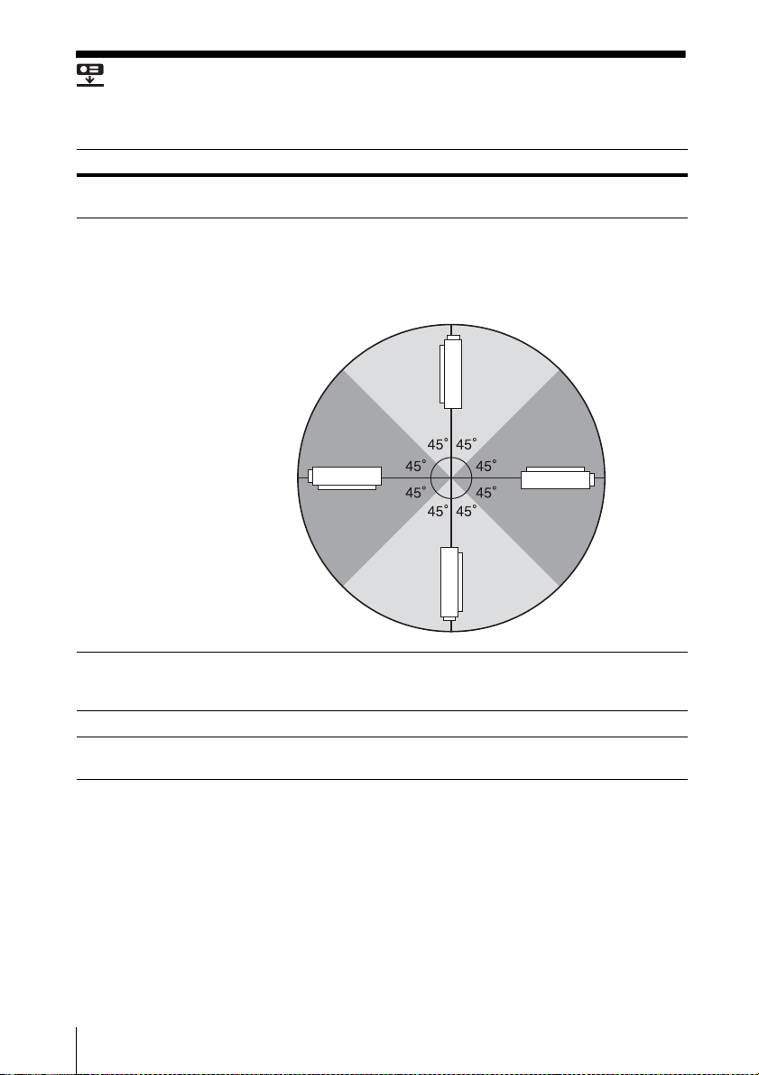
About Remote Commander operation
• Direct the Remote Commander toward the
remote control receiver.
• The shorter the distance between the
Remote Commander and the projector is,
the wider the angle within which the
Remote Commander can control the
projector becomes.
• If there is any obstruction between the
Remote Commander and the remote
control receiver on the projector, the
projector may not be able to receive
signals from the Remote Commander.
Location and Function of Controls
7
Preparation
B
Connecting the Projector
Notes
• Turn off all equipment before making any connections.
• Use the proper cables for each connection.
• Insert the cable plugs firmly; Loose connections may reduce performance of picture signals or
cause a malfunction. When pulling out a cable, be sure to grip it by the plug, not the cable itself.
• For more information, refer also to the instruction manuals of the equipment you are connecting.
Connecting a Computer
Connection with a computer is explained for each input signal.
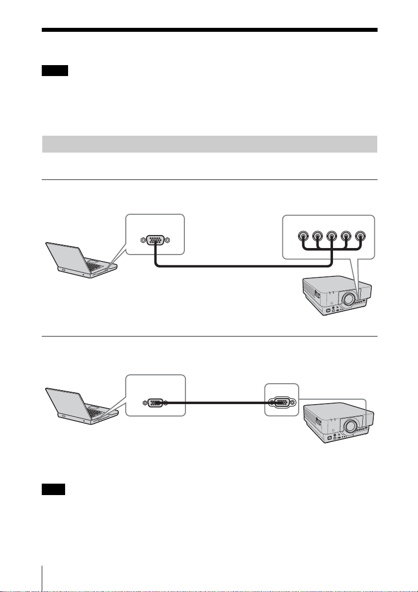
INPUT A
For connection when there is some distance between a computer and the projector.
Computer
RGB output
terminal
Mini D-sub 15-pin – BNC cable
(not supplied)
R/PR G/Y B/PB HD VD
INPUT A
INPUT B
For connecting a computer with an RGB output terminal.
RGB output
terminal
Mini D-sub 15-pin
cable (not supplied)
Computer
Note
INPUT B RGB
It is recommended that you set the resolution of your computer to 1920 × 1200 pixels (VPLFH500L) or 1024 × 768 pixels (VPL-FX500L) for the external monitor.
8
Connecting the Projector
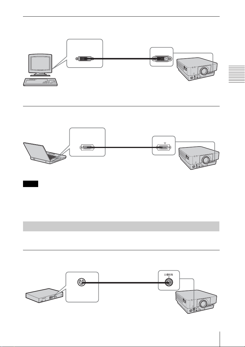
INPUT C
For connecting a computer with a DVI-D output terminal.
DVI-D output
terminal
DVI-D cable
(not supplied)
Computer
INPUT C DVI-D
INPUT D (VPL-FH500L only)
For connecting a computer with a HDMI output terminal.
HDMI output
terminal
HDMI cable
(not supplied)
Computer
Notes
INPUT D HDMI
• The HDMI terminal of this projector is not compatible with DSD (Direct Stream Digital) Signal
or CEC (Consumer Electronics Control) Signal.
• Use HDMI-compatible equipment which has the HDMI Logo.
• Use a high speed HDMI cable(s) on which the cable type logo is specified. (Sony products are
recommended.)
Preparation
Connecting a Video Equipment
Connections with a VHS video deck, DVD player, or BD player are explained for each input
signal.
S VIDEO IN
For connecting video equipment with an S-video output terminal.
S video cable (not supplied)
Connecting the Projector
Video equipment
S video output
terminal
9
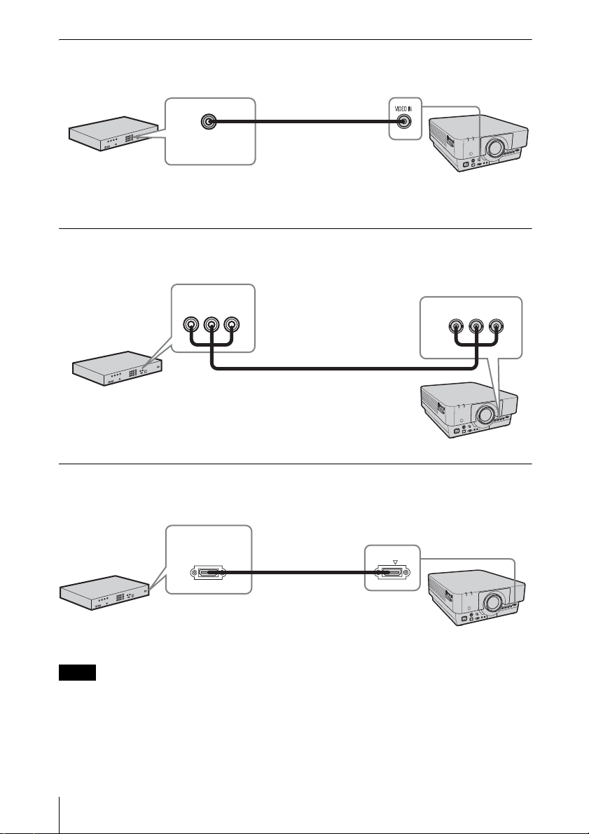
VIDEO IN
For connecting video equipment with a video output terminal.
Video – BNC cable
(not supplied)
Video equipment
Video output
terminal
INPUT A
For connection when there is some long distance between the video equipment and projector.
BPR output
YP
terminal
Component – BNC cable (not supplied)
Video equipment
R/PR G/Y B/PB
INPUT A
INPUT D (VPL-FH500L only)
For connecting video equipment with a HDMI output terminal.
HDMI output
terminal
HDMI cable
(not supplied)
Video equipment
INPUT D HDMI
Notes
• The HDMI terminal of this projector is not compatible with DSD (Direct Stream Digital) Signal
or CEC (Consumer Electronics Control) Signal.
• Use HDMI-compatible equipment which has the HDMI Logo.
• Use a high speed HDMI cable(s) on which the cable type logo is specified. (Sony products are
recommended.)
10
Connecting the Projector
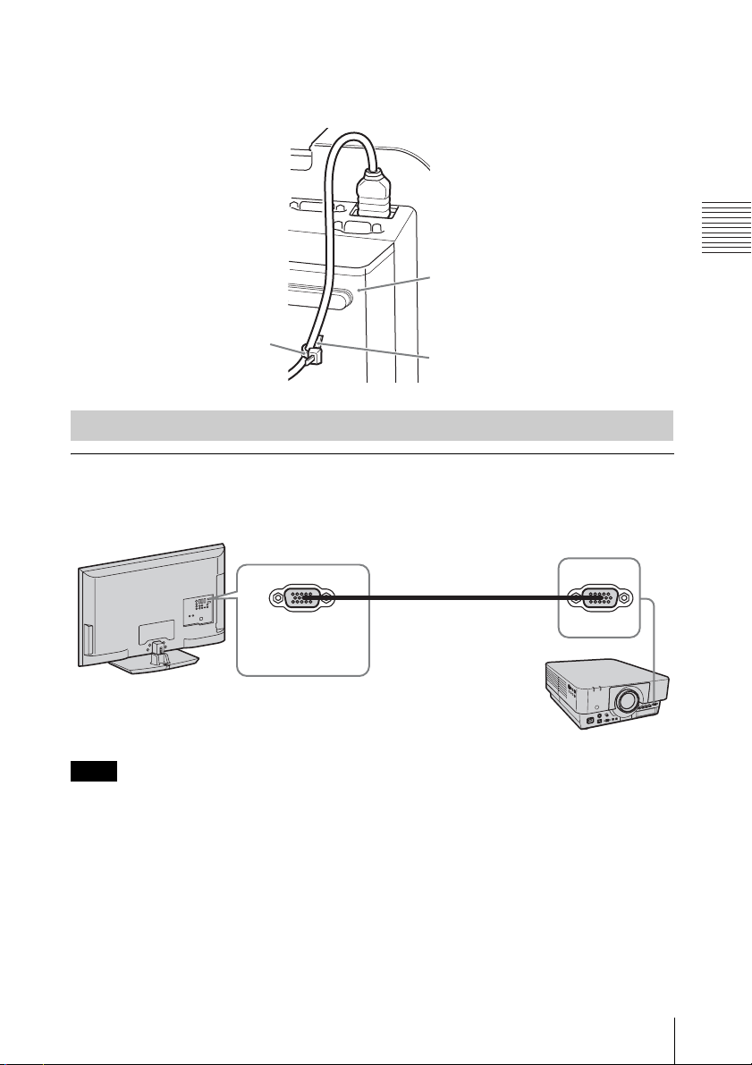
To attach the HDMI cable
Fix the cable to the cable tie holder at the bottom of the projector, using a commercially
available cable tie, as in the illustration.
Use a cable tie of less than 1.9 mm × 3.8 mm in thickness.
Bottom of the projector
Cable tie
(commercially available)
Cable tie holder
Connecting an External Monitor
OUTPUT
Projected images can be output to display equipment such as a monitor.
Display equipment
OUTPUT
Mini D-sub 15-pin cable
(not supplied)
Note
RGB input
terminal
This terminal outputs the image. Output as a computer signal input from the RGB input terminal
(INPUT A, INPUT B) or a video signal input from the YPBPR input terminal (INPUT A).
MONITOR
Preparation
Connecting the Projector
11
Projecting/Adjusting an Image
B
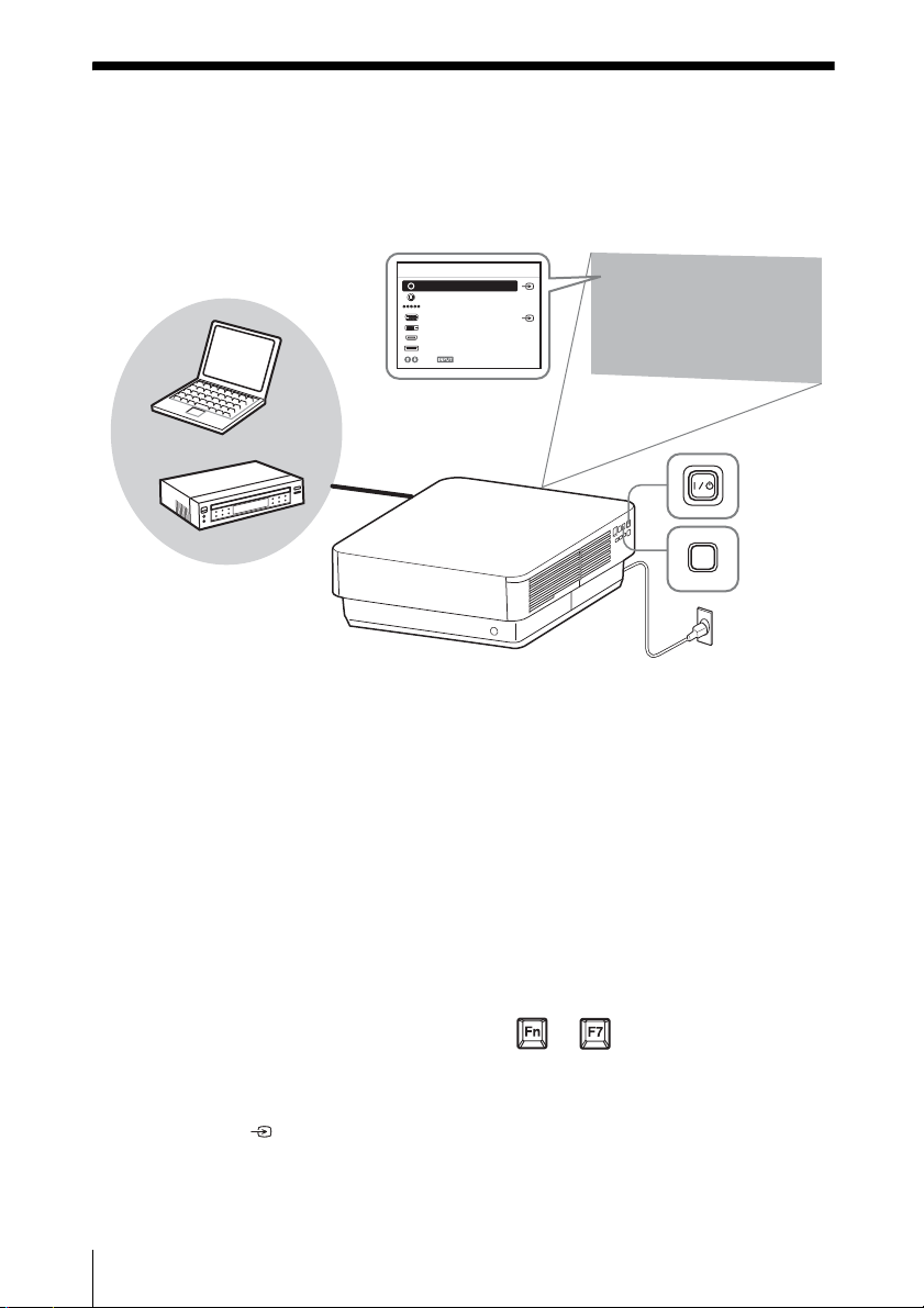
Projecting an Image
The size of a projected image depends on the distance between the projector and screen. Install
the projector so that the projected image fits the screen size. For details on projection distances
and projected image sizes, see
4
Computer
“Projection Distance and Lens Shift Range” (page 56).
Input select window
Input
5
Video
S-Videoo
Input-A
Input-B
Input-C
Input-D
Input-E
Sel Skip
6
2
3
Video equipment
1 Plug the AC power cord into a wall
outlet.
2 Connect all equipment to the projector
(page 8).
3 Turn on the projector.
Press the ?/1 key on the projector or the
? key on the Remote Commander.
4 Turn on the connected equipment.
5 Select the input source.
Press the INPUT key on the projector to
display the input select window. Press
the INPUT key repeatedly or the V/v
key to select an image to be projected.
The signal icon appears on the right
side in the input select window when a
signal is input.
5
INPUT
Projector
You can select the input source using
Direct input select keys on the Remote
Commander
1
(page 5).
Wall outlet
6 Switch your computer to output to
external display by changing your
computer’s setting.
How to switch the computer to output to
the projector varies, depending on the
type of computer.
(Example)
+
7 Adjust the focus, size, and position of
the projected image (page 13).
12
Projecting an Image
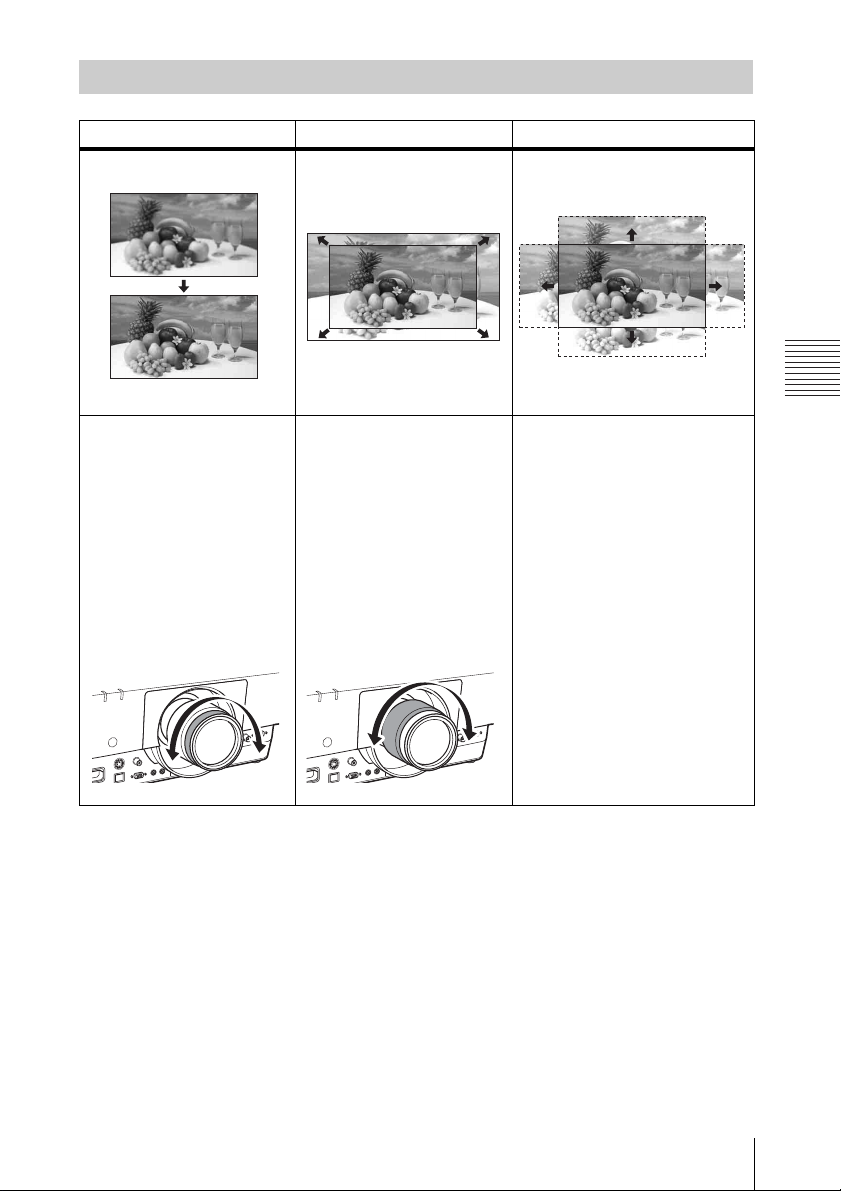
Adjusting the Focus, Size, and Position of the Projected image
Focus Size (Zoom) Position (Lens shift)
When attaching the Electric
focus lens
Press the FOCUS key on the
projector or the Remote
Commander then press the B/
bkey (or V/v key) to adjust
the focus.
When attaching the Manual
focus lens
Turn the Focus Ring to adjust
the focus.
When attaching the Electric
zoom lens
Press the ZOOM key on the
projector or the Remote
Commander then press the B/
bkey (or V/v key) to adjust
the size.
When attaching the Manual
zoom lens
Turn the Zoom Ring to adjust
the size.
Press the SHIFT key on the
projector or the Remote
Commander then press the V/v/
B/b key to adjust the position.
To return the lens to the center
position of the projected image
Press the RESET key on the
Remote Commander while
adjusting.
Projecting/Adjusting an Image
Projecting an Image
13
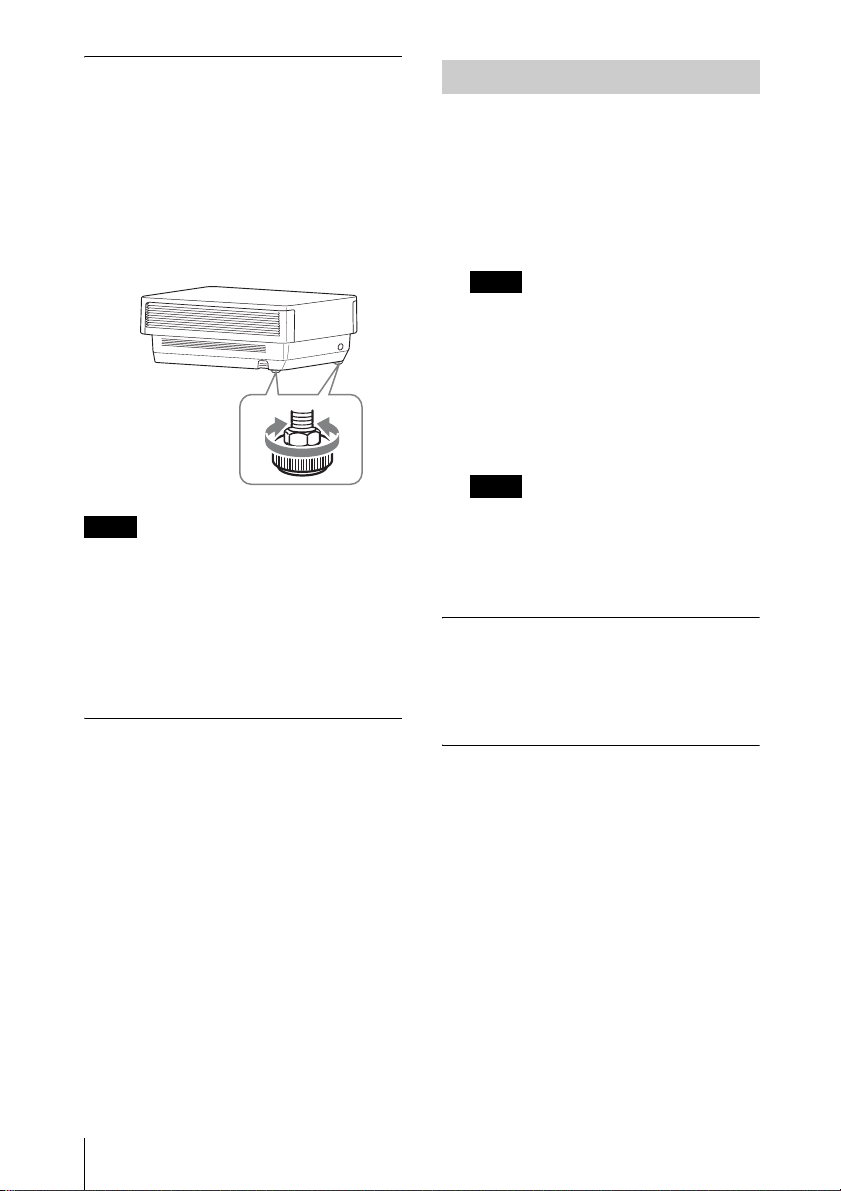
Adjusting the tilt of the projector
with the rear feet (adjustable)
When the projector is installed on an uneven
surface, you can adjust using the rear feet
(adjustable). To correct any trapezoidal
distortion of the projected image, use the
Keystone feature (page 5,
You can also broaden the adjustment range
by removing the nuts from the rear feet
(adjustable).
Notes
• Be careful not to let the projector down on
your fingers.
• Do not push hard on the top of the projector
with the rear feet (adjustable) extended. It
may cause a malfunction.
• Since the Keystone adjustment is an
electronic correction, the image may be
deteriorated.
26).
Displaying a pattern for adjusting
an image
You can display a pattern for adjusting the
projected image with the PATTERN key on
the Remote Commander. Press the
PATTERN key again to restore the previous
image.
Turning Off the Power
1 Press the ?/1 key on the main unit or
1 key on the Remote Commander.
The message appears if you press the ?/
key on the main unit. Press it again
1
according to the message.
The fan continues to run for a while to
reduce internal heat.
Note
Do not turn off the projector soon after the
lamp lights. It may cause a malfunction of
the lamp (does not light, etc.).
2 Unplug the AC power cord from the
wall outlet.
You may unplug the AC power cord
before the fan stops.
Note
To move the projector just after turning it
off, be sure to wait until the fan stops
before unplugging the AC power cord.
Unplugging the AC power cord before the
fan stops may cause a malfunction.
To erase the confirmation message
The message disappears if you press any key
other than the ?/1 key on the main unit or 1
key on the Remote Commander, or if you do
not press any key for a while.
To turn off the power with the key
on the main unit without a
confirmation message being
displayed
Hold the ?/1 key on the main unit pressed
for a few seconds.
14
Projecting an Image
B Adjustments and Settings Using a Menu
Using a MENU
Note
The menu displays used for the explanation below may be different depending on the model you are
using.
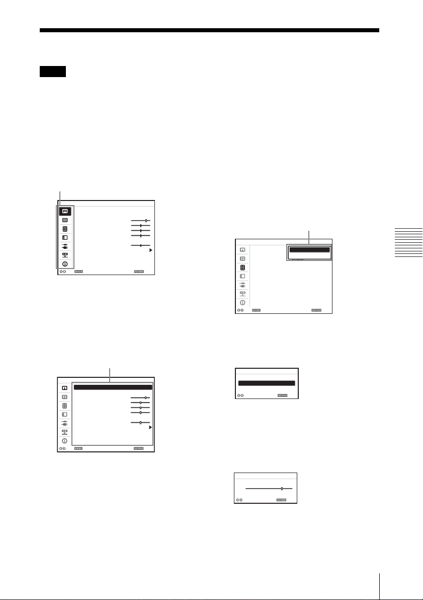
1 Press the MENU key to display the
menu.
2 Select the setting menu.
Use the V or v key to select the setting
menu then press b or ENTER
Setting menu
Picture
Picture Mode Standard
Reset
Contrast 80
Brightness 50
Color 50
Hue 50
Color Temp. Middle
Sharpness 50
Expert Setting
Sel Set
key.
Back
3 Select the setting item.
Use the V or v key to select the setting
menu then press b or ENTER key.
To return to the selection screen of the
setting menu, press the B key or the
RETURN key.
Setting items
Picture
Picture Mode Standard
Reset
Contrast 80
Brightness 50
Color 50
Hue 50
Color Temp. Middle
Sharpness 50
Expert Setting
Sel Set
Back
4 Make the setting or adjustment for the
selected item.
Menu operation differs depending on the
setting item. If the next menu window is
displayed, select the item according to
the operations in step 3 and then press
the ENTER key to register the setting.
To return to the selection screen of the
setting items, press the B key or the
RETURN key. Also, to reset the setting
value of an item to its factory preset
value, press the RESET key during
setting or adjusting.
Using a pop-up menu
Press the V/v/B/b key to select an item.
Press the ENTER key to register the
setting. The previous screen is restored.
Selecting items
Function
Smart APA
CC Display
Pic. Muting Mode Shutter
Lamp Mode Standard
Lamp Light Mode Lamp 1
Background Blue
Start Up Image On
Sel Set
On
Off
Back
Using the setting menu
Press the V or v key to select the item.
Press the ENTER key to register the
setting. The previous screen is restored.
Picture Mode
Dynamic
Standard
Presentation
Sel Back
Using the adjustment menu
To increase the number, press the V or b
key and to decrease the number, press
the v or B key. Press the ENTER key to
register the setting. The previous screen
is restored.
Contrast
Min
80
Adjust Back
Max
5 Press the MENU key to clear the
menu.
The menu disappears automatically if no
key is pressed for a while.
Adjustments and Settings Using a Menu
Using a MENU
15

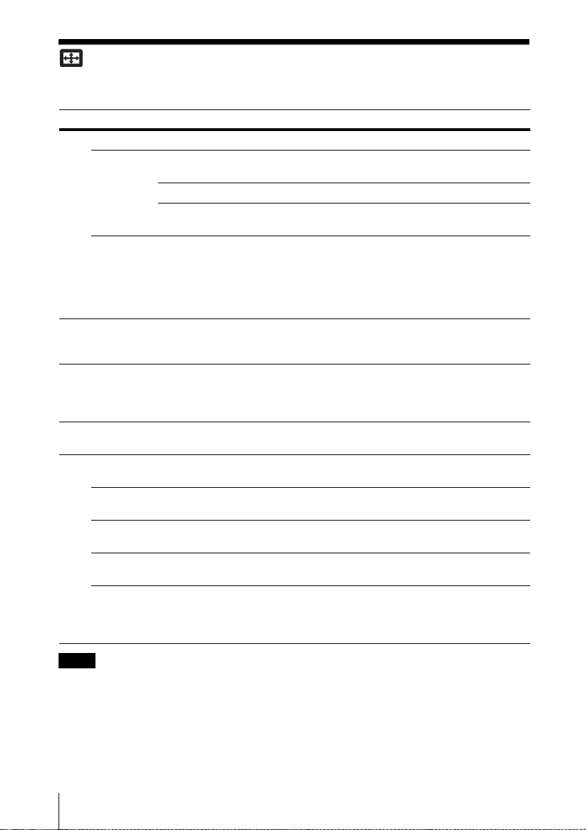
The Picture Menu
For adjusting the picture for each input signal.
Setting items Description
Picture Mode Dynamic: Emphasizes the contrast to produce a “dynamic and vivid” picture.
Reset The picture settings are initialized to their factory preset values.
Contrast The higher the setting, the greater the contrast. The lower the setting, the lower
Brightness The higher the setting, the brighter the picture. The lower the setting, the darker
*2 *4
Color
*2 *4 *5
Hue
Color Temp.
Sharpness
Expert Setting
Film
Mode
Black Level
Adj.
(Adjust)
Gamma
Mode
Standard: Makes the picture be natural and well balanced.
Presentation
*1
: Makes the picture bright to suit for a presentation.
However, “Picture Mode” and “Custom1,” “Custom2,” and “Custom3” of
“Color Temp.” do not return to the factory preset values.
the contrast.
the picture.
The higher the setting, the greater the intensity. The lower the setting, the lower
the intensity.
The higher the setting, the more greenish the picture becomes. The lower the
setting, the more reddish the picture becomes.
*3
High/Middle/Low: The higher the temperature, the more bluish the picture.
The lower the temperature, the more reddish the picture.
Custom1/ Custom2/ Custom3: An adjusted color temperature setting can be
stored for each item.
The factory settings are Custom1: High, Custom2: Middle, Custom3: Low.
*6
The higher the setting, the sharper the picture. The lower the setting, the softer
the picture.
Auto: Precisely reproduces the image from a film source to suit the original
*2 *7
film source. Normally, select this option.
Off: Select this option if the images are rough around the edges when “Auto” is
selected.
High/Low/Off: Emphasizes dark portions of the projected image to suit your
taste.
*2
Graphics: Improves the reproduction of halftones. Photos can be reproduced
*1
in natural tones.
Text: Contrasts black and white. Suitable for images that contain lots of text.
DICOM GSDF Sim.
*8
: Gamma setting is in accordance with the Grayscale
Standard Display Function (GSDF) of the Digital Imaging and
Communications in Medicine (DICOM) standards.
Notes
*1: When a computer signal is input, this option is available.
*2: When a video signal is input, this option is available.
*3: When “Picture Mode” is set to the item other than “Presentation,” this option is available.
*4: When a B & W signal is input, this option is not available.
*5: When an analog TV signal is input, this option may not available, depending on the color system.
*6: When a video signal is input, this option is available.
16
The Picture Menu

*7: When a progressive signal is input, this option is not available.
*8: Available when a computer signal is input from the DVI-D input terminal (INPUT C) and HDMI
input terminal (INPUT D). This projector is not to be used as a device for medical diagnosis
(VPL-FH500L).
Adjustments and Settings Using a Menu
The Picture Menu
17
The Screen Menu
For adjusting the size, position, and aspect ratio of the projected image for each input signal.
Setting items Description
*1
Aspect
When the
computer
signal is
input
When the
video signal
is input
V Center
*2 *3
Vertical Size
Over Scan
*3
Adjust Signal
APA
Phase
Pitch
Shift
*4 *5
*4
*6
Changes the aspect ratio of the projected image. (page 20).
Full1: Displays the image to fit the maximum projected image size without
changing the aspect ratio of the input signal.
Full2: Displays the image
to fit the maximum projected image size.
Normal: Displays the image on the center point of the projected image
without changing the resolution of the input signal or enlarging the image.
4:3: Displays the image to fit the maximum projected image size with an
aspect ratio fixed to 4:3.
16:9: Displays the image to fit the maximum projected image size with an
aspect ratio fixed to 16:9.
*2
Full
: Displays the image to fit the maximum projected image size.
Zoom: Display the center point of the projected image to zoom.
Adjust the whole projected image by moving up and down on the screen.
As the selected number increases, the screen moves up, and as the selected
number decreases, the projected image moves down.
*2 *3
Reduces or enlarges the image vertically.
The projected image is enlarged as the setting increases and reduced as the
setting decreases. If the subtitle of a movie, etc. cannot be seen, use this
together with “V Center.”
On/Off: Hides the outline of the image when set to “On.” Select “On” if
noise appears along the edge of the image.
*6
Adjusts the image of signal. Use this item if the edge of the image is cut and
reception is bad.
Automatically adjusts the projected image to an optimum quality when you
press the ENTER key.
*4
Adjusts the dot phase of the display pixel and the input signal. Set to the
value where looks clearest.
The higher the setting, the wider the horizontal image elements (pitch). The
lower the setting, the narrower the horizontal image elements (pitch).
H: The higher the setting, the farther right the image is projected on the
screen. The lower the setting, the image farther left.
V: The higher the setting, the farther up the image is projected on the screen.
The lower the setting, the image farther down.
Notes
*1: • Note that if the projector is used for profit or for public viewing, modifying the original picture
by switching to the aspect mode may constitute an infringement of the rights of authors or
producers, which are legally protected.
• Depending on the input signal, setting items for aspect ratio or some other setting items cannot
be set in some cases, or changing the aspect ratio setting may have no effect.
• A part of the image may be displayed in black, depending on the setting item.
*2: Available for VPL-FH500L only.
18
The Screen Menu

*3: Available when a video signal is input from the YPBPR input terminal (INPUT A), DVI-D input
terminal, HDMI input terminal, and optional adapter.
*4: Available when a computer signal is input from the RGB input terminal (INPUT A, INPUT B).
*5: If the projected image includes large amount of black portion around it, the APA function will
not work properly and a part of the image may not be displayed on the screen and also optimum
image cannot be obtained, depending on the type of input signal. In this case, adjust the “Phase,”
“Pitch,” and “Shift” items manually.
*6: Available when a computer signal is input from the RGB input terminal (INPUT A, INPUT B)
or a video signal is input from the YP
only when “Aspect” is set to “Zoom.”
BPR input terminal (INPUT A). This option is available
Adjustments and Settings Using a Menu
The Screen Menu
19
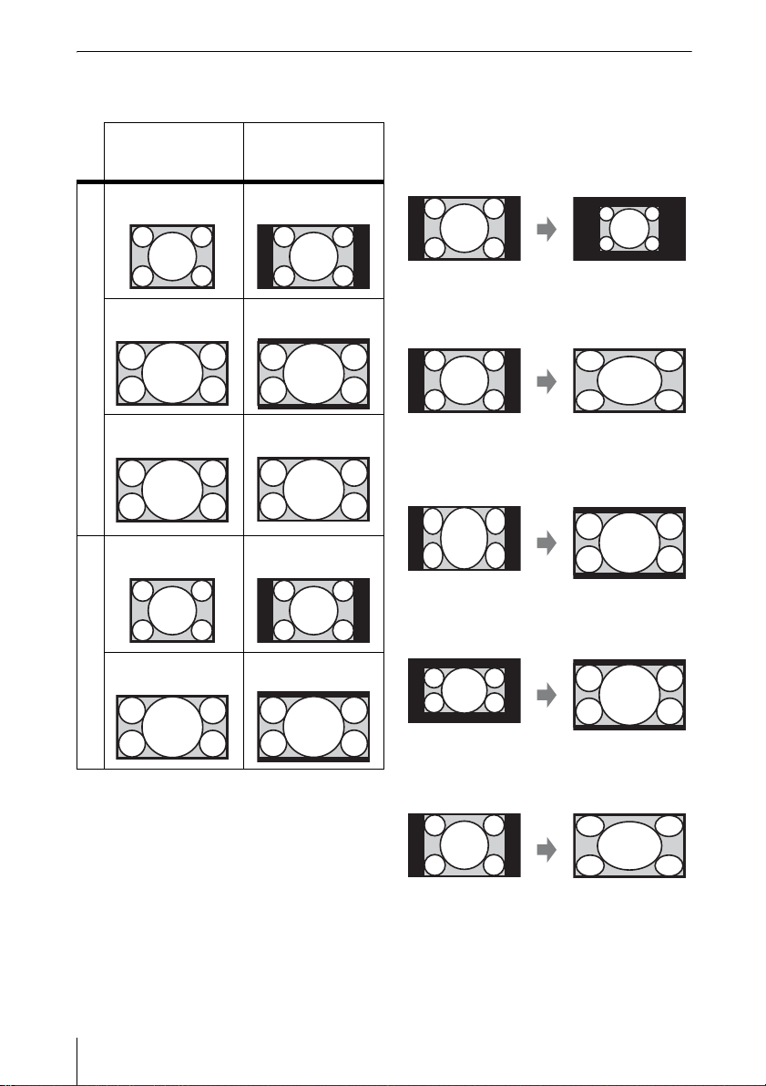
Aspect
VPL-FH500L
Input signal Recommended
(4:3) (Full1)
setting value and
projected image
*1 *2
*1: If you select “Normal,” the image is
projected in the same resolution as the
input signal without changing the aspect
ratio of the original image.
*2: If you select “Full2,” the image is projected
(16:9) (Full1)
*1 *2
to fit the projected image size, regardless
of the aspect ratio of the image.
Computer signal
(16:10) (Full1)
*1
*3: Depending on the input signal, the
projected image may be projected as
illustrated below. In this a case, select
“16:9.”
(4:3) (4:3)
*3 *5
*4: Depending on the input signal, the image
may be projected as illustrated below. In
this a case, select “Zoom.”
(16:9) (16:9)
*4 *5
Video signal
*5: If you select “Full,” the image is projected
to fit the projected image size, regardless
of the aspect ratio of the image.
20
The Screen Menu
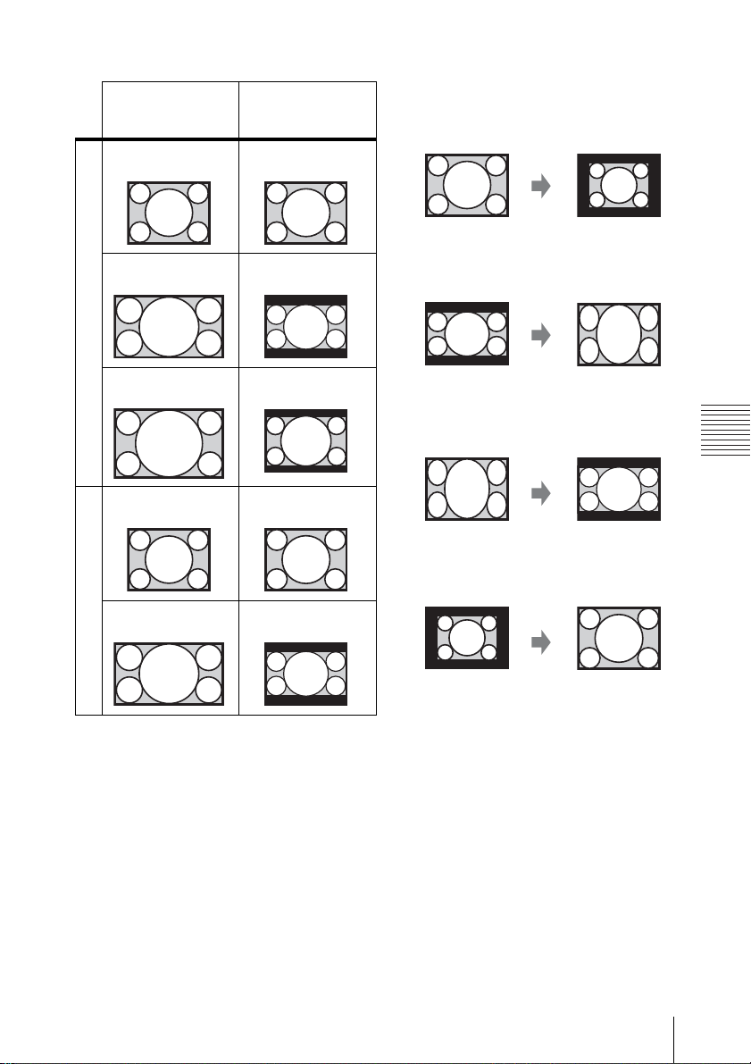
VPL-FX500L
Input signal Recommended
(4:3) (Full1)
setting value and
projected image
*1
*1: If you select “Normal,” the image is
projected in the same resolution as the
input signal without changing the aspect
ratio of the original image.
*2: If you select “Full2,” the image is projected
(16:9) (Full1)
*1 *2
to fit the projected image size, regardless
of the aspect ratio of the image.
Computer signal
(16:10) (Full1)
*1 *2
*3: Depending on the input signal, the
projected image may be projected as
illustrated below. In this a case, select
“16:9.”
Adjustments and Settings Using a Menu
(4:3) (4:3)*3
*4: Depending on the input signal, the image
may be projected as illustrated below. In
this a case, select “Zoom.”
(16:9) (16:9)
*4
Video signal
The Screen Menu
21

The Function Menu
The Function menu is used for setting various functions of the projector.
Setting items Description
Smart APA On/Off; When set to “On,” executes APA automatically when a signal is
CC Display CC1/CC2/CC3/CC4/Text1/Text2/Text3/Text4: Select the closed
Pic.Muting Mode Shutter: Close the shutter when the PIC MUTING key is pressed.
Lamp Mode High/Standard: When set to “High,” the image becomes brighter, and
Lamp Light Mode The projector has a function for switching between the two lamps.
Background Black/Blue: Selects the background color of the projected image when no
Start Up Image On/Off: When set to “On,” the Start Up Image is displayed on the screen
*1
input.
caption service (Captions or Text).
Off: Closed caption does not appear.
Image: Cuts off the projected image when the PIC MUTING key is
pressed.
power consumption becomes higher.
When one lamp is turned off, the other is turned on automatically to avoid
interrupt of operation.
Auto: Lights the lamp that is set to be used for shorter duration than the
other when starting up the projector.
Lamp 1/Lamp 2: Lights the selected lamp. If the selected lamp is turn off,
the other is turned on automatically. It is recommended to select this item
when you cannot replace the lamp immediately.
signal is input.
upon startup of the projector.
Note
*1: Executes APA when a computer signal is input via the RGB input terminal (INPUT A, INPUT
B).
22
The Function Menu

The Operation Menu
The Operation Menu is used for setting for the operations by using the menu or the Remote
Commander.
Setting items Description
Language Selects the language used in the menu and on-screen displays.
Menu Position
Status On: All on-screen statuses are enabled.
IR Receiver Front & Rear/Front/Rear: Selects the remote control receivers (IR Receiver)
ID Mode All/1/2/3: Assigns an ID number to the projector. When set to “All,” you can
Security Lock
Panel Key Lock On/Off: When set to “On,” locks all the control panel keys of the projector.
Lens Control On/Off: When set to “On,” you can adjusts the lens (Focus, Zoom, and Shift)
*1
Bottom Left/Center: For selecting the position of the menu displayed on the
projected image.
Off: Turn off the on-screen displays except for the menus, message when
turning off the power, and warning messages.
on the front and rear of the projector.
control the projector with the Remote Commander independently of the
assigned ID Mode. Refer also to “ID MODE 1/2/3 switch” of the Remote
Commander on page 7.
*2
On/Off: This function enables restriction of the projector to authorized users
by password. The setting procedures for security locking are as follows:
1 Select “On” then press the ENTER key to display the setting menu.
2 Input the password with the MENU, V/v/B/b, and ENTER keys. (The
default password setting is “ENTER, ENTER, ENTER, ENTER.”)
3 Input a new password with the MENU, V/v/B/b, and ENTER keys.
4 Enter the password again to confirm.
Enter the password when you turn on the projector after disconnecting and
reconnecting the AC power cord.
When it is set to “Off,” you can cancel the security lock. You are required to
input the password again.
If you fail to enter the correct password after three consecutive times, the
projector cannot be used. In this case, press the ?/1 key to go Standby mode
then turn on the power again.
However, you can enable operation by performing the following even when
“Panel Key Lock” is set to “On.”
• Press and hold the ?/1 key for approximately 10 seconds during Standby
mode.
c The projector turns on.
• Press and hold the MENU key for approximately 10 seconds during power
on.
c “Panel Key Lock” is set to “Off” and enables operation of all control panel
keys on the projector.
from the Remote commander or the projector. To prevent unintentional
operation, set it to “Off” after adjusting the lens.
Adjustments and Settings Using a Menu
Notes
*1: Available for VPL-FH500L only
*2: You will not be able to use the projector if you forget your password. If you call qualified Sony
personnel because you have forgotten the password, you will be asked to verify the projector’s
The Operation Menu
23

serial number and your identity. (This process may differ in other countries/regions.) Once your
identity has been confirmed, we will provide you with the password.
24
The Operation Menu

The Connection/Power Menu
The Connection/Power menu is used for setting for the connections and power.
Setting items Description
Network Setting
IP Address Setup Aut o (DHC P): The IP address is assigned automatically from the
IP Address/ Subnet
Mask/ Default
Gateway/Primary
DNS/Secondary
DNS
Input-A Signal Sel. Auto/Computer/Video GBR/Component: When set to “Auto,”
Color System Auto/ NTS C3. 58/PAL/SECAM/NTSC4.43/PAL-M/PAL-N: When set
Standby Mode
Power Saving Mode Lamp Cutoff: The lamp turns off automatically and power
Direct Power On On/Off: When set to “On,” you can turn the power on without going
*2
DHCP server such as a router.
Manual: To specify the IP Address manually.
When “Manual” is selected for “IP Address Setup,” select the item
with the b or B key and input the value with v or V key. When all
items are entered, select Apply then press the ENTER key. The entered
settings will be registered.
selects the type of video signal input automatically when “Input-A” is
selected with the INPUT key.
to “Auto,” selects the color system automatically when “S Video” or
“Video” is selected with the INPUT key.
Standard/Low: When set to “Low,” lowers power consumption in
Standby mode.
consumption is reduced if no signal is input for about 10 minutes. The
lamp lights again when a signal is input or any key is pressed. In Lamp
Cutoff, the ON/STANDBY indicator lights in orange (page 32).
Standby: The power will be turned off automatically and the projector
goes to Standby mode if no signal is input for about 10 minutes.
Off: The Power Saving Mode is released.
to Standby mode when the AC power cord is connected to a wall
outlet. You can also unplug the AC power cord without going to
Standby mode when you turn off the projector.
You may unplug the AC power cord without going to Standby mode.
*1
*1
Adjustments and Settings Using a Menu
Notes
*1: The image may not be adjusted properly depending on the type of input signal. In such a case,
adjust it manually to suit to the connected equipment.
*2: When “Standby Mode” is set to “Low,” the network and network control function cannot be
operated while the projector is in standby mode.
The Connection/Power Menu
25
The Installation Menu
The Installation menu is used for installing the projector.
Setting items Description
Image Flip HV/H/V/Off: Flips the projected image horizontally and/or vertically
Installation Attitude Link to Image Flip/Right Side Up/Upside Down/Front Down/Front
according to the installation method.
Up: Change the cooling setting to suit to the installation attitude. When set
to “Link to Image Flip,” the cooling setting changes based on the setting of
“Image Flip.”
reliability.
*1
Continuing to use the wrong setting may affect component
Front Up
Upside DownRight Side Up
Front Down
High Altitude Mode On/Off: Set to “On” when using the projector at an altitude of 1,500 m or
Screen Aspect
V Keystone
26
The Installation Menu
*3 *4
higher. Continuing to use the wrong setting may affect component
reliability.
*2
16:10/16:9/4:3: For switching the display area to suit to the screen.
The higher the setting, narrower the top of the projected image. The lower
the setting, the narrower the bottom.

Setting items Description
Panel Alignment
*2 *5
This feature allows you to adjust the gaps in the color of characters or the
picture.
When set to “On,” “Adjust Color” and “Pattern Color” can be assigned and
adjusted.
Adjust Item: Selects how to make adjustments from below.
Shift: Shifts the whole picture and makes adjustments.
Zone: Selects the desired range and makes adjustments.
Adjust Color: Assigns the desired color to adjust the gaps in color. Select
“R” (Red) or “B” (Blue) to make adjustments based on “G” (Green).
Pattern Color: Select “R/G” (Red and Green) or “R/G/B” (White, all
colors) when “Adjust Color” is “R” (Red). Select “B/G” (Blue and Green)
or “R/G/B” (White, all colors) when the “Adjust Color” is “B” (Blue).
Adjust: The shift adjustment and zone adjustment of the color selected in
“Adjust Color” can be made with V/v/B/b buttons.
Color Matching
*2 *6
Adjust/Reset: For correcting the brightness and color of the whole
projected image manually from the signal level in six steps.
Notes
*1: Select “Link to Image Flip” only for horizontal installation. Be sure to select “Front Down” or
“Front Up” for a vertical installation, to match the installation direction of the projector.
*2: Available for VPL-FH500L only
*3: Depending on the position adjusted with the lens shift feature, the aspect ratio of the image may
change from the original or projected image may be distorted with Keystone adjustment.
*4: Since the Keystone adjustment is an electronic correction, the image may be deteriorated.
*5: Depending on the adjustment value of “Panel Alignment,” the color and aspect ratio may be
changed.
*6: The brightness and color of the projected image may not match completely, even after you adjust
“Brightness” and “Color.”
Adjustments and Settings Using a Menu
The Installation Menu
27

The Information Menu
The Information menu enables you to confirm various information on the projector, such as the
total usage hours of a lamp.
Items Description
Model Name Displays the model name.
Serial No. Displays the serial number.
fH / fV (horizontal
frequency/vertical
frequency)
Signal type Displays the type of the current input signal.
Lamp Timer Indicates the usage time and status of a lamp.
Note
*1: These items may not be displayed depending on the input signal.
*1
Displays the horizontal frequency/vertical frequency of the current input
signal.
( : Lamp 1/ : Lamp 2)
: The lamp is in lights.
: The lamp does not light.
: The lamp is in abnormal status.
28
The Information Menu

B Network
Using Network Features
Connection to the network allows you to operate the following features:
• Checking the current status of the projector via a Web browser.
• Remotely controlling the projector via a Web browser.
• Receiving the Mail Report for the projector.
• Making the network settings for the projector.
• Supports network monitoring and control protocol (Advertisement, PJ Talk, PJ Link, SNMP,
AMX DDDP [Dynamic Device Discovery Protocol]).
Notes
• When connecting this projector with the network, consult with the network administrator. The
network must be secured.
• When using this projector connected with the network, access the Control window via a Web
browser and change the access limitation of the factory preset values (page 30). It is recommended
to change the password regularly.
• When the setting on the Web browser is completed, close the Web browser to log out.
• The menu displays used for the explanation below may be different depending on the model you
are using.
• Supported Web browsers are Internet Explorer 6/7/8.
• The menu displays only English.
• If the browser of your computer is set to [Use a proxy server] when you have access to the projector
from your computer, click the check mark to set accessing without using a proxy server.
Displaying the Control Window of the Projector with a Web Browser
1 Connect the LAN cable.
LAN cable
(straight type)
(not supplied)
LAN terminal
then press the Enter key on your
computer.
http://xxx.xxx.xxx.xxx
(xxx.xxx.xxx.xxx: IP address for the
projector)
You can confirm the IP address of the
projector under “Network Setting” on
the Connection/Power menu.
Network
Hub or router, etc
2 Set the network settings for the
projector using “Network Setting” on
the Connection/Power menu
(page 25).
3 Start a web browser on the computer,
enter the following in the address field,
The following window appears in the
Web browser:
Using Network Features
29

Once you make the network settings, you
can open the Control window only by
performing step 3 of this procedure.
How to operate the Control window
Switching the page
Click one of the Page Switching buttons to
display the desired setting page.
Page Switching buttons
Setting the access limitation
You can limit a user for accessing any
particular page.
Administrator: Allowed access to all
pages
User: Allowed access to all pages except
the Setup page
Set under [Password] of the Setup page.
When you access the Setup page for the first
time, enter “root” for user name and enter
nothing for password.
The name of the administrator is preset to
“root.”
Confirming the Information regarding the Projector
You can confirm the current settings for the
projector on the Information page.
Information area
Operating the Projector from a Computer
You can control the projector from the
computer on the Control page.
Entry area for [Administrator]
Entry area for [User]
When you change the password, input a new
password after deleting the password
(*****) that was set.
Note
If you forget your password, consult with
qualified Sony personnel.
30
Using Network Features
Operation area
The functions of the keys shown in the
operation area are the same as those of the
keys on the supplied Remote Commander.
Using the Mail Report Function
Set the Mail Report function on the Setup
page.
Entered values will not be applied unless
you click on [Apply].

1 Click on [Owner information] to enter
the owner information recorded in the
Mail Report.
Owner information button
1
2 Set the timing of the Mail Report.
Click on [Mail Report] to open the Mail
Report page.
Lamp Reminder (Lamp1): Set the
timing for lamp replacement. To reset
Lamp Reminder, replace the lamp on
the projector (page 36).
Maintenance Reminder: Set the timing
for maintenance. To reset
Maintenance Reminder, check the
RESET check box and then click on
[Apply].
Mail Report button
3 Enter the outgoing e-mail address in
the Email Address box then check the
Report Timing check box of the Mail
Report to be sent.
4 Set the mail account for sending mail
reports.
Mail Address: Enter the e-mail address.
Outgoing Mail Server (SMTP): Enter
the address of outgoing mail server
(SMTP).
Required Authentication: Check this
check box if authentication is required
for sending e-mail.
Requires the use of POP
Authentication before send email
(POP before SMTP): Check this
check box to arrange for POP
authentication to be performed before
sending e-mail.
Incoming Mail Server (POP3): Enter
the address of the incoming-mail
server (POP3) to be used for POP
authentication.
Account Name: Enter the mail account.
Password: Enter the password.
SMTP Authentication: Check this
check box to arrange for SMTP
authentication to be performed before
sending e-mail.
Account Name: Enter the mail account.
Password: Enter the password.
Network
5 Confirm the contents of the Mail
2
3
4
6
5
Report.
When you click on [View] is pressed, the
contents of the
displayed.
Mail Report are
6 Send the test mail.
Check on the Send test mail check box
then click on [Apply] to send your test
mail to the e-mail address you set.
Notes
• The mail report function is not available
because the network which Outbound Port25
Blocking is used cannot be connected to the
SMTP server.
• You cannot use the following characters to
enter the characters in the text box: “ ' ”, “ “
”, “ \ ”, “ & ”, “ < ”, “ > ”
Using Network Features
31

Others
B
Indicators
The indicators allow checking the status and notify you of abnormal operation of the projector.
If the projector exhibits abnormal status, address the problem in accordance with the table
below.
ON/STANDBY indicator
Status Meaning/Remedies
Lights in red The projector is in Standby mode.
Flashes in green • The projector is ready to operate after having been turned on.
Lights in green The projector’s power is on.
Lights in orange The projector is in Power Saving Mode (lamp cut off).
Flashes in red The projector is in abnormal status. Symptoms are indicated by
Flashes twice The internal temperature is unusually high. Check the items below.
Flashes six times Unplug the AC power cord from a wall outlet. After checking that the
Other number of
flashes
• The lamp cools after the projector is turned off.
number of flashes. Address the problem in accordance with the
following. If the symptom is shown again, consult with qualified Sony
personnel.
• Check to see if nothing is blocking the ventilation holes.
• Check to see if the air filter is not clogged.
• Check if “Installation Attitude” on the Installation menu is correctly
selected.
ON/STANDBY indicator goes out, plug the power cord to a wall
outlet again then turn on the projector.
Consult with qualified Sony personnel.
LAMP/COVER indicator
Status Meaning/Remedies
Flashes in red Symptoms are indicated by number of flashes. Address the problem in
Flashes twice The lamp cover or air filter unit are not attached securely.
Flashes three/four/
five times
Flashes six times The lens is not mounted on the projector (page 40).
32
Indicators
accordance with the following.
The temperature of a lamp is high (Three times: only Lamp 1, Four
times: only Lamp 2, Five times: Lamp 1 and Lamp 2). Turn off the
power and wait for the lamp to cool then turn on the power again. If
the symptom is shown again, the lamp may be burnt out. In such a
case, replace the lamp with a new one (page 36).

Messages List
When any of the messages listed below appears on the projected image, address the problem in
accordance with the table below.
Message Meaning/Remedy Page
High temp.! Lamp off in
1 min.
Frequency is out of
range!
Please check Input-A
Signal Sel.
Please replace Lamp 1
and Filter.
Please replace Lamp 2
and Filter.
Please replace Lamp 1,
Lamp 2 and Filter.
Projector temperature is
high. High Altitude
Mode should be “On” if
the projector is being
used at high altitude.
Not applicable! Invalid key pressed. 5
The panel keys are
locked!
Lens Control is locked! “Lens Control” is set to “Off.” 23
Error occurred on
Lamp1.
Lamp 2 is lit.
Error occurred on Lamp
2.
Lamp 1 is lit.
The shutter did not
work.
Check the items below.
• Check to see if nothing is blocking the ventilation holes.
• Check to see if the air filter is not clogged.
• Check if “Installation Attitude” on the Installation menu is
correctly selected.
Change the output setting of the connected equipment to one
for signals supported by the projector.
Set “Input-A Signal Sel.” to “Auto” or select the input signal
type to suit to the input signal.
Replace the lamp with a new one and replace the air filter. The
message appears whenever you turn on the power until you
replace the lamp.
At an altitude of 1,500 m or higher, if you are not using the
projector, check the items below.
• Check that nothing is blocking the ventilation holes.
• Check that the air filter is not clogged.
• Check if “Installation Attitude” on the Installation menu is
correctly selected.
“Panel Key Lock” is set to “On.” 23
An error occurred in the lamp and another lamp is lit. –
Consult with qualified Sony personnel. –
3, 26,
38
53
25
36, 38
3, 26,
38
Others
Messages List
33

Troubleshooting
Before asking to have the projector repaired, try to diagnose the problem, following the
instructions below.
Symptom Remedy Page
The power is not turned
on.
No image. Check if the connecting cable is connected to external
On-screen display does
not appear.
The aspect ratio of the
display is not right/the
image is displayed
smaller /a portion of
image does not appear.
The image is a
trapezoid.
Edges of the image are
cut off or dark.
The image is dark/too
bright.
The image is not clear. Check if the projector is in focus. 13
The image is noisy. Check if the connecting cable is connected to external
Check if the AC power cord is firmly connected. –
When the “Panel Key Lock” is set to “On,” you cannot turn on
the projector using the ?/1 key on the projector.
If the lamp, lamp cover, or air filter unit is not attached
securely, the projector cannot be turned on.
equipment properly.
Check if the computer signal is set for output to an external
monitor. If you set your computer, such as a notebook
computer, to output the signal to both your computer’s display
and an external monitor, the picture of the external monitor
may not appear properly. Set your computer to output the
signal to only an external monitor.
Check if the input source is correctly selected. 12
Check if the picture is muted. 6
The on-screen display does not appear when “Status” in the
Operation menu is set to “Off.”
The image may not be displayed correctly with an input signal
the projector cannot interpret correctly. In such a case, set
“Aspect” manually.
Check if “Screen Aspect” is correctly selected. 26
The images become trapezoidal because of the projection
angle. In such a case, you can correct the trapezoidal
distortion, using a Keystone feature.
If you use the Lens Shift function with a setting outside the
recommended range, edges of the image may be cut off or
appear dark. Use a setting within the normal range for the Lens
Shift function.
The settings for “Brightness,” “Contrast,” and “Lamp Mode”
affect brightness of the image. Check if the value is
appropriate.
The image will be dark when the lamp is burnt out. Check
“Lamp Timer,” and replace the lamp with a new one if
necessary.
The picture will not be clear if condensation has accumulated
on the lens. In such a case, let the projector sit for about two
hours with the power on.
equipment properly.
36, 38
18, 20
5, 26
16, 22
23
8
12
23
56
28
–
–
34
Troubleshooting

Symptom Remedy Page
The Remote
Commander does not
work.
The fan is noisy. The sound from the fan is often greater than normal to cool the
Check that the batteries are installed correctly. –
Check that the batteries are not exhausted. –
Check if the “ID Mode” of the projector corresponds to that of
the Remote Commander.
Check the setting for “IR Receiver.” 23
lamp in the following cases.
• When “Lamp Mode” is set to “High.”
• The projector is in at high altitude (“High Altitude Mode” is
set to “On”).
• Temperature is very high.
If the ventilation holes are blocked, the internal temperature of
the projector rises and the fan noise becomes larger.
7, 23
22, 26
3
Troubleshooting
Others
35

Replacing the Lamp
Replace the lamp with a new one if a message displayed on the projected image or the LAMP/
COVER indicator notifies you to replace the lamp (pages 32, 33).
The projector incorporates two lamps. Before replacement, check which lamp is to be replaced
(page 32).
Use an LMP-F330 projector lamp (not supplied) for replacement.
Caution
• The lamp remains hot after the projector is
turned off. If you touch the lamp, you may
burn your finger. When you replace the
lamp, wait for at least an hour after
turning off the projector for the lamp to
cool sufficiently.
• Do not allow any metallic or inflammable
objects into the lamp replacement slot after
removing the lamp, otherwise it may cause
electrical shock or fire. Do not put your
hands into the slot.
• If the lamp breaks, contact qualified
Sony personnel. Do not replace the lamp
yourse lf.
• When removing the lamp, be sure to pull it
out straight, by holding it by the specified
part. If you touch a part of the lamp other
than the specified part, you may be burned or
injured. If you pull out the lamp while the
projector is tilted, the pieces may scatter if
the lamp breaks any may cause injury.
Before starting
The projector incorporates two lamps.
Check the number of flashes of the LAMP/
COVER indicator. This enables you to be
informed of a lamp to be replaced.
Flashes three times: Replace Lamp 1.
Flashes four times: Replace Lamp 2.
Flashes five times: Replace both Lamp 1
and Lamp 2.
1 Turn off the projector, and disconnect
the AC power cord from a wall outlet.
2 When the lamp has cooled
sufficiently, loosen the two screws of
the lamp cover on the side panel (
slide the lamp cover slightly to the rear
by the tabs (
cover (
Lamp cover
Lamp 1
2), then open the lamp
3).
Screws
Lamp 2
1),
Ta b
36
Replacing the Lamp
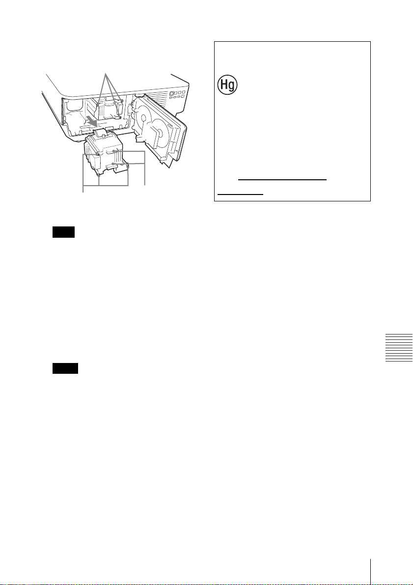
3 Loosen the three screws on the lamp
then pull out the lamp by its grab.
Screws
Screws
Note
Lamp 1 and Lamp 2 are of the same type.
They are installed in opposite vertical
orientation to each other. When removing,
note the orientation of each lamp.
Grab
4 Insert the new lamp all the way in until
it is securely in place. Tighten the
three screws.
Disposal of the used lamp
For the customers in
the U.S.A. and Canada
Lamp contains
mercury. Dispose
according to applicable
local, state/province and
federal laws.
For additional information,
see www.sony.com/
mercury
5 Close the lamp cover and tighten the
two screws.
Notes
• The lamp cover cannot be closed if the
screws that secure the lamps are
loosened.
• Be sure to install the lamp and lamp
cover securely as it was. If not, the
projector cannot be turned on.
When lamp replacement is completed
Replace the air filter cartridge (page 38).
Replacing the Lamp
Others
37

Replacing the Air Filter Cartridges
After replacing the lamp, replace the air filter cartridges.
When replacing the air filter cartridges, replace all 4 cartridges supplied with the replacement
lamps.
Caution
If you continue to use the air filter cartridges, dust may accumulate, clogging it. As a result, the
temperature may rise inside the unit, leading to a possible malfunction or fire.
1 Make sure the AC power cord is
disconnected.
2 Slide the air filter cover slightly to the
rear while holding the lock button to
remove the air filter cover.
Rear
Front
Air filter cover
Lock button
v
3 Pull out the air filter cartridge straight
by the grab of the air filter unit while
pushing out one tab at a time on both
sides.
Air filter unit
(right)
Ta bs
(right)
Tabs (left)
Grab
Air filter unit (left)
4 Remove the four air filter cartridges
(two in each air filter unit) from the air
filter units and attach new cartridges to
the units.
When attaching the air filter cartridge to
the cartridge holder, push the air filter
cartridge in fully until the tabs of the
cartridge holder click (4 points each air
filter cartridge, a total of 8 points).
The two air filter units are installed in the
right and left positions.
38
Replacing the Air Filter Cartridges

Ta bs
Air filter cartridge
6 Close the air filter cover.
Note
Be sure to attach the air filter unit firmly; the
power cannot be turned on if it is not closed
securely.
Ta bs
Air filter
cartridge
Cartridge
holder
5 Return the air filter units to the
projector.
The top and bottom of the air filter unit
have different shapes, as illustrated
below. Be careful of orientation when
installing them.
Tabs (left)
Bottom (side with a
grooved section)
Slide the air filter unit in fully until the
tabs on the projector click to hold it in
place (2 points each air filter unit, a total
of 4 points).
Tabs (right)
Others
Replacing the Air Filter Cartridges
39

Attaching/Removing the Projection Lens
Notes
• Turn off the projector and disconnect the AC power cord from a wall outlet before you remove/
attach the projection lens.
• Be careful not to drop the projection lens.
• Avoid removing/attaching the lens with the projector installed suspended from a ceiling.
• Avoid touching the lens surface.
• For usable projection lenses and a lens adapter, see “Specifications” (page 48).
Attaching
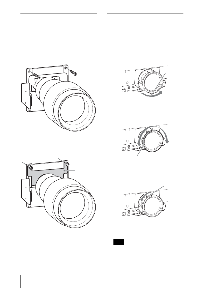
1 Loosen the four screws that secure the
front panel to remove the front panel
in the direction of the front.
Front panel
Screws
Screws
VPLL-FM22/ZM32/ZM42/ZM102/
Z4007/Z4011:
A Removing the compensating glass
(page 41)
*1
VPLL-FM21
ZM32/ZM42/ZM102:
B Attaching the projection lens
adapter (page 42)
VPLL-ZM101
B Attaching the projection lens
adapter (page 42)
C Attaching the shading sheet
(page 44)
VPLL-Z4007/4008/Z4011/Z4015/
Z4019/Z4025/Z4045
There is no need to attach the
projection lens adapter to the
projector.
/ZM31*1/ZP41/FM22/
*1
:
2 Make the preparations required for
the projection lens you are using.
40
Attaching/Removing the Projection Lens
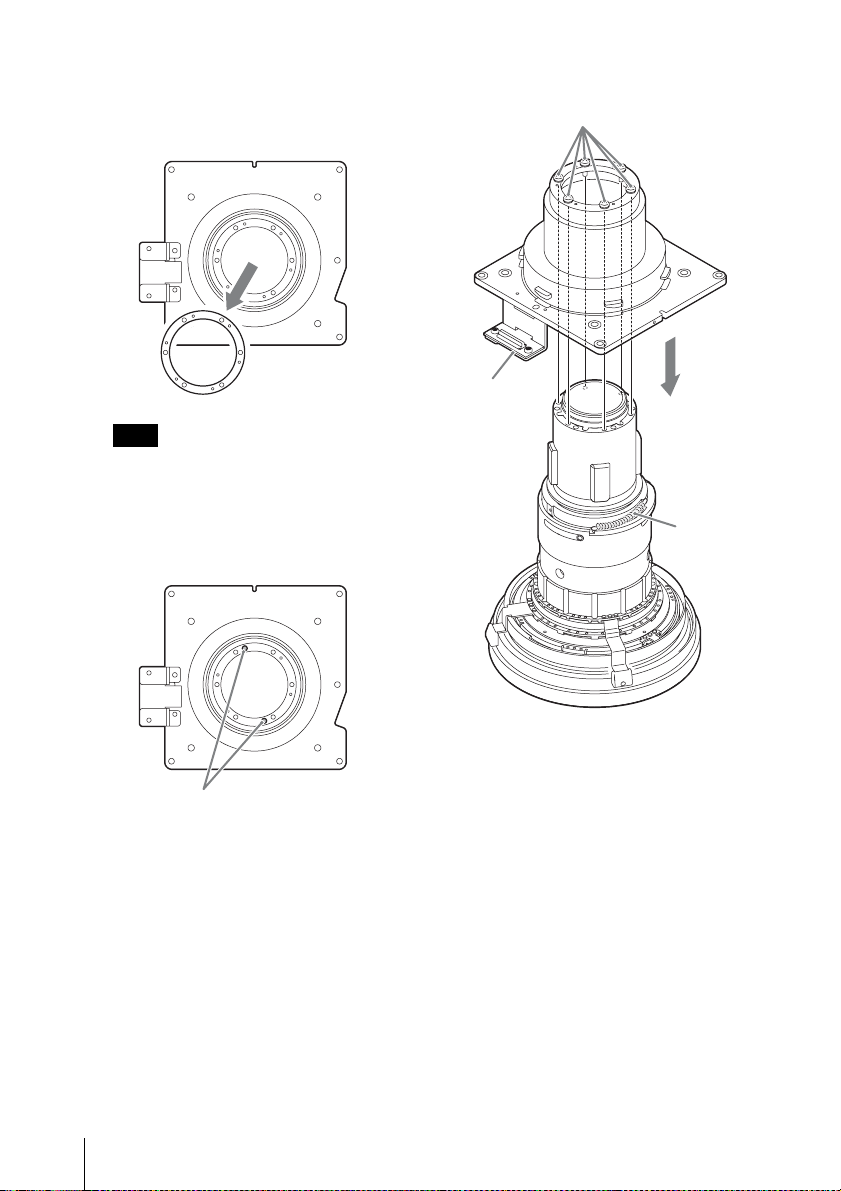
3 Insert the four screws (supplied with
the projector) to the flange section of
the projection lens.
Flange
section

4 Align the connectors on the projector
with those on the projection lens then
insert the lens all the way in until it is
securely in place.
Connector section
Connector section
5 Tighten the four screws attached in
step 3.
6 Replace the front panel and fasten it
with the four screws.
When attaching the VPLL-Z4007
Adjust the focus. (“D VPLL-Z4007:
Adjusting the peripheral focus” (page 44))
A VPLL-FM22/ZM32/ZM42/ZM102/
Z4007/Z4011: Removing the
compensating glass
Before attaching the projection lens to the
projector, it is required to remove the
compensating glass from the lens mounting
part of the projector.
To remove the compensating glass
Turn the compensating glass
counterclockwise as illustrated then pull it
out towards you.
To attach the compensating glass
Insert the compensating glass with the arrow
mark on the glass aligned with the mark (F)
on the lens mounting part of the projector,
and turn the glass clockwise.
Attaching/Removing the Projection Lens
Others
41

B VPLL-FM21*1/ZM31*1/ZP41/
FM22/ZM32/ZM42/ZM101*
1
/ZM102:
Attaching the projection lens
adapter
Before attaching the projection lens to the
projector, it is required to attach the lens
adapter to the projection lens.
Insert the projection lens into the lens
adapter as illustrated and fasten it with the
four screws supplied with the lens adapter.
1
For the VPLL-FM21*
ZM101*
1
/ZM31*1/ZP41/
Use the PK-F500LA1 lens adapter.
PK-F500LA1
42
Attaching/Removing the Projection Lens
Slide until it clears the gap

When mounting a VPLL-ZP41
Engage the two connectors between the lens
adapter and the projection lens, as
illustrated.
For the VPLL-FM22/ZM32/ZM42/
ZM102
Use the PK-F500LA2 lens adapter.
PK-F500LA2
Slide until it clears the gap
Attaching/Removing the Projection Lens
Others
43
C VPLL-ZM101*1: Attaching the
shading sheet
Before attaching the projection lens to the
projector, it is required to attach the shading
sheet supplied with the lens adapter after
attaching the lens adapter.
1 Remove the two screws from the lens
adapter.
2 Fit the shading sheet to the projection
lens as illustrated and fasten it to the
lens with the two screws.
D VPLL-Z4007: Adjusting the
peripheral focus
When attaching the VPLL-Z4007, adjust the
peripheral focus in addition to the usual
focus adjustment.
1 Project an image and adjust the
projected image size with the zoom
lever.
Zoom lever
2 Rotate and fix the peripheral focus
ring at the center of the movable
range.
Peripheral focus ring
*1: VPL-FX500L only.
44
Attaching/Removing the Projection Lens
Shading
sheet
3 Adjust the center point focus of the
projected image with the focus lever.
Focus lever
4 Rotate the peripheral focus ring to
adjust the focus of peripheral area.
Note
If rotating the peripheral focus ring all the
way does not adjust the focus of the
peripheral area, see “When the peripheral
focus cannot be adjusted” (page 45).

Check the center point of the projected
image. If the center point of the projected
image is focused, the adjustment is
complete. If not, repeat steps 3 and 4.
When the peripheral focus cannot be
adjusted
According to the installation conditions, the
peripheral focus ring may not adjust the
focus of the peripheral image. In this case,
adjust the focus by changing the number of
spacers.
1 Remove the projection lens (page 47).
3 Remove the two screws of the spacer
attached inside the adapter.
Adapter
Spacer
2 Loosen the six screws of the adapter of
the projection lens and remove the
adapter.
Screws (6)
Adapter
Screws (2)
4 Depending on the focus condition of
peripheral area, add or remove a
spacer.
A spare spacer is supplied with the lens.
Multiple spacers are attached to the
adapter at the time of factory delivery.
If the peripheral image is better
focused when the peripheral
focus ring is rotated clockwise all
the way through
Add a spacer.
Others
Attaching/Removing the Projection Lens
45
If the peripheral image is less
focused when the peripheral
focus ring is rotated clockwise all
the way through
Remove a spacer.
Note
When removing or adding the spacer,
handle with care and avoid from getting
injured.
5 Attach the spacer to the adapter with
the two screws.
6 Attach the adapter to the projection
lens with the six screws.
Screws (6)
Connector
Spring
Screws (2)
46
Attaching/Removing the Projection Lens
Adjust the connector part of the adapter
to the position of the spring of the
projection lens as shown above, and
firmly attach the adapter to the
projection lens.
7 Attach the projection lens to the
projector (page 40).
8 Perform steps 1 to 4 of the focus
adjustment on page 44.

Removing
Installing the
1 Loosen the four screws that secure the
front panel (1), and remove the front
panel, pulling it forward (2).
2 Loosen the four screws that secure the
projection lens then pull it out straight.
When loosening the screws, support the
lens with your hands so that it will not
fall.
Screws
Screws
Note
If the lens was shifted with lens shift
adjustment, the screws may be too
constricted to loosened. In such a case,
adjust to shift the lens to the center position
(page 13).
Optional Adapter
You can install the optional adaptor in
INPUT E of the terminals section of the
projector.
1 Turn off the power of the projector and
disconnect the power cable.
2 Slide the slot cover for the optional
adaptor attached to the terminals to the
right and remove it.
INPUT B RGB
INPUT C DVI-D
B
INPUT D HDMI
OUTPUT
MONITOR
Slot cover
R/P
R
G/Y HD VD
INPUT A
B/P
3 Insert the optional adapter as far as it
goes.
Example: 3G-SDI Input Adaptor BKM-
PJ20 (not supplied)
4 Tighten the two screws on the optional
adapter.
Installing the Optional Adapter
Others
47

Specifications
Item Description
Model name VPL-FH500L/VPL-FX500L
Display system 3 LCD system
Display device Size of effective
display area
Number of pixels VPL-FH500L: 6,912,000 pixels (1920 × 1200 × 3) pixels
Light source High-pressure mercury lamp, 330 W type
Light output 7000 lm
Displayable
scanning
frequency
*2
Display resolution Computer signal
inputt
Video signal
input
Color system NTSC3.58, PAL, SECAM, NTSC4.43, PAL-M, PAL-N,
Computer and
INPUT A RGB/YP
video signal input/
output
INPUT B RGB input terminal: Mini D-sub 15-pin female, RGB:
INPUT C DVI-D input terminal: DVI-D 24-pin (Single link), DVI
INPUT D
INPUT E
*3
*3
S VIDEO IN S video input terminal: Mini DIN 4-pin, Y: 1 Vp-p ± 2
VIDEO IN Video input terminal: BNC, 1 Vp-p ± 2 dB, sync
VPL-FH500L: 0.95” (24.1 mm) × 3, Aspect ratio 16:10
VPL-FX500L: 0.99" (25.0 mm) × 3, Aspect ratio 4:3
VPL-FX500L: 2,359,296 pixels (1024 × 768 × 3) pixels
*1
(when “Lamp Mode” is set to “High”)
Horizontal: 14 kHz to 93 kHz, Vertical: 47 Hz to 93 Hz
Maximum display resolution: 1920 × 1200 dots
Panel display resolution:
VPL-FH500L: 1920 × 1200 dots
VPL-FX500L: 1024 × 768 dots
NTSC, PAL, SECAM, 480/60i, 576/50i, 480/60p, 576/
50p, 720/60p, 720/50p, 1080/60i, 1080/50i, 1080/60p,
1080/50p, 1080/24p
*3
, 1080/30p
*3
PA L6 0
sync/Y: 1 Vp-p ± 2 dB, sync negative, 75 ohms
BPR input terminal: 5BNC female, G with
terminated, RGB/P
BPR: 0.7 Vp-p ± 2 dB, 75 ohms
terminated, Sync signal: TTL level high impedance,
positive/negative
0.7 Vp-p ± 2 dB, 75 ohms terminated, Sync signal: TTL
level high impedance, positive/negative
1.0 compliant, HDCP support
HDMI input terminal: Digital RGB/YPBPR
For optional adapters
dB, sync negative, 75 ohms terminated, C: (burst signal)
0.286 (NTSC)/0.3 (PAL/SECAM) Vp-p ± 2 dB, 75 ohms
terminated
negative, 75 ohms terminated
48
Specifications

Item Description
Model name VPL-FH500L/VPL-FX500L
Computer and
video signal input/
output
Control signal
input/output
Operating
temperature/
Operating
humidity
Storage
temperature/
Storage humidity
Power
requirements
Power
consumption
Power
consumption
(Standby Mode)
Power
consumption
(Networked
Standby Mode)
Heat dissipation AC 100 V to
OUTPUT MONITOR output terminal: Mini D-sub 15-pin
AC 100 V to
120 V
AC 220 V to
240 V
AC 100 V to
120 V
AC 220 V to
240 V
AC 100 V to
120 V
AC 220 V to
240 V
120 V
AC 220 V to
240 V
female, G with sync/Y: 1 Vp-p ± 2 dB, sync negative, 75
ohms terminated, RGB/P
terminated, Sync signal: HD, VD 4V (open), 1 Vp-p
(75 ohms), positive/negative
RS-232C terminal: D-Sub 9 pin female
LAN terminal: RJ45, 10BASE-T/100BASE-TX
CONTROL S input terminal (DC power supply):
Stereo mini jack, 5 Vp-p, Plug in power DC 5 V
CONTROL S output terminal: Stereo mini jack
0 °C to 40 °C (32 °F to 104 °F)/35% to 85% (no
condensation)
–20 °C to +60 °C (–4 °F to +140 °F)/10 % to 90 %
VPL-FH500L: 100 V to 240 V AC, 4.9 A to 2.0 A, 50/60
Hz
VPL-FX500L: 100 V to 240 V AC, 4.8 A to 2.0 A, 50/60
Hz
VPL-FH500L: 490 W / VPL-FX500L: 480 W
VPL-FH500L: 460 W / VPL-FX500L: 460 W
VPL-FH500L: 0.1 W (when “Standby Mode” is set to
“Low”)
VPL-FX500L: 0.1 W (when “Standby Mode” is set to
“Low”)
VPL-FH500L: 0.2 W (when “Standby Mode” is set to
“Low”)
VPL-FX500L: 0.2 W (when “Standby Mode” is set to
“Low”)
VPL-FH500L: 11.0 W (LAN) (when “Standby Mode” is
set to “Standard”)
VPL-FX500L: 13.0 W (LAN) (when “Standby Mode” is
set to “Standard”)
VPL-FH500L: 10.0 W (LAN) (when “Standby Mode” is
set to “Standard”)
VPL-FX500L: 12.0 W (LAN) (when “Standby Mode” is
set to “Standard”)
VPL-FH500L: 1672 BTU/h / VPL-FX500L: 1638 BTU/h
VPL-FH500L: 1569 BTU/h / VPL-FX500L: 1569 BTU/h
BPR: 0.7 Vp-p ± 2 dB, 75 ohms
Others
Specifications
49

Item Description
Model name VPL-FH500L/VPL-FX500L
Outside
dimensions
530 × 213 × 545 mm (207/8" × 83/8" × 2115/32") (W/H/
D)
530 × 204 × 545 mm (20
D) (without protrusions)
*8
Mass
Supplied
accessories
Optional
accessories
*4 *5
Approx. 20 kg (40 lb)
See “Checking the Supplied Accessories” in the supplied
Quick Reference Manual.
Projector Lamp LMP-F330 (for replacement)
Projector Suspension Support PSS-630
Projector Suspension Support Joint Pole PSS-630P
Projection Lens VPLL-FM22
Projected image size: 40" to 300" (1.02 m to 7.62 m),
Maximum external dimensions (W × H × D): 88 × 88 ×
169 mm (3
15
/32" × 3 15/32" × 6 21/32"), Mass: Approx.
1 kg (2.1 lb)
Projection Lens VPLL-ZM42*6: Manual focus/zoom,
Projected image size: 40" to 300" (1.02 m to 7.62 m),
Maximum external dimensions (W × H × D): 88 × 88 ×
159 mm (3
15
/32" × 3 15/32" × 61/4"), Mass: Approx.
0.7 kg (1.4 lb)
Projection Lens VPLL-ZP41*7: Electric focus/zoom,
Projected image size: 40" to 300" (1.02 m to 7.62 m),
Maximum external dimensions (W × H × D): 117 × 110
× 198 mm (4
19
/32" × 411/32" × 725/32"), Mass: Approx.
1.5 kg (3.2 lb)
Projection Lens VPLL-ZM102*6: Manual focus/zoom,
Projected image size: 40" to 300" (1.02 m to 7.62 m),
Maximum external dimensions (W × H × D): 88 × 88 ×
198 mm (3
15
/32" × 3 15/32" × 725/32"), Mass: Approx.
1.5 kg (3.3 lb)
Projection Lens VPLL-ZM101
zoom, Projected image size: 40" to 300" (1.02 m to 7.62
m), Maximum external dimensions (W × H × D): 100 ×
100 × 222 mm (3
15
/16" × 3 15/16" × 8 3/4"), Mass:
Approx. 1.8 kg (4 lb)
Projection Lens VPLL-Z4007: Manual focus/zoom,
Projected image size: 60" to 300" (1.52 m to 7.62 m),
Maximum external dimensions (W × H × D): 157× 150 ×
217 mm (6
3
/16" × 5 29/32" × 8 19/32"), Mass: Approx. 2.0
kg (4.4 lb)
Projection Lens VPLL-4008: Manual focus, Projected
image size: 40" to 600" (1.02 m to 15.24 m), Maximum
external dimensions (W × H × D): 148 × 133 × 240 mm
13
(5
/16" × 5 1/4" × 9 7/16"), Mass: Approx. 2.6 kg (5.6 lb)
7
/8" × 81/32" × 2115/32") (W/H/
*6
: Manual focus,
*7 *8
: Manual focus/
50
Specifications

Item Description
Model name VPL-FH500L/VPL-FX500L
Optional
accessories
*4 *5
Projection Lens VPLL-Z4011: Electric focus/zoom,
Projected image size: 60" to 600" (1.52 m to 15.24 m),
Maximum external dimensions (W × H × D): 157 × 150
× 265 mm (6
3
/16" × 5 29/32" × 10 7/16"), Approx. 3.7 kg
(8 lb)
Projection Lens VPLL-Z4015: Electric focus/zoom,
Projected image size: 40" to 600" (1.02 m to 15.24 m),
Maximum external dimensions (W × H × D): 148 × 133
× 231 mm (5
13
/16" × 5 1/4" × 93/32"), Mass: Approx.
3 kg (6.6 lb)
Projection Lens VPLL-Z4019: Electric focus/zoom,
Projected image size: 40" to 600" (1.02 m to 15.24 m),
Maximum external dimensions (W × H × D): 148 × 133
× 212 mm (5
13
/16" × 5 1/4" × 811/32"), Mass: Approx.
3.1 kg (6.7 lb)
Projection Lens VPLL-Z4025: Electric focus/zoom,
Projected image size: 40" to 600" (1.02 m to 15.24 m),
Maximum external dimensions (W × H × D): 148 × 133
× 243 mm (5
13
/16" × 51/4" × 99/16"), Mass: Approx.
2.8 kg (6.2 lb)
Projection Lens VPLL-Z4045: Electric focus/zoom,
Projected image size: 60" to 600" (1.52 m to 15.24 m),
Maximum external dimensions (W × H × D): 148 × 133
× 235 mm (5
13
/16" × 51/4" × 9 1/4"), Mass: Approx. 3 kg
(6.6 lb)
Projection Lens Adapter PK-F500LA1
Projection Lens Adapter PK-F500LA2
HD-SDI/SDI Input Adaptor BKM-FW16
3G-SDI Input Adaptor BKM-PJ20
Notes
*3
*3
The values for mass and dimensions are approximate.
*1: When attaching the VPLL-ZP41.
*2: For details, refer to “Acceptable Input Signals” on page 53.
*3: Available for VPL-FH500L only
*4: Not all optional accessories are available in all countries and area. Please check with your local
Sony Authorized Dealer.
*5: Information on accessories in this manual is current as of March 2016.
*6: To attach the projection lens to the projector, the PK-F500LA2 projection lens adapter is
required.
*7: To attach the projection lens to the projector, the PK-F500LA1 projection lens adapter is
required.
*8: Available for VPL-FX500L only.
Design and specifications of the unit, including the optional accessories, are subject to change
without notice.
Others
Specifications
51

Pin assignment
DVI-D terminal (DVI-D, female) RGB input terminal (Mini D-sub 15-
pin, female)
1
9
17
8
16
24
1 T.M.D.S.
14 +5 V Power
Data2–
2 T.M.D.S.
Data2+
3 T.M.D.S.
Data2 Shield
15 Ground (return
for +5 V)
16 Hot Plug
Detect
4 NC 17 T.M.D.S
Data0–
5 NC 18 T.M.D.S
Data0+
6 DDC Clock 19 T.M.D.S
Data0 Shield
7 DDC Data 20 NC
8NC 21NC
9 T.M.D.S.
Data1–
10 T.M.D.S.
Data1+
11 T.M.D.S.
Data1 Shield
22 T.M.D.S
Clock Shield
23 T.M.D.S
Clock+
24 T.M.D.S
Clock–
12 NC
13 NC
1 Video input
(red) R
2 Video input
9Power supply
input for DDC
10 GND
(green) G
3Video input
11 GND
(blue) B
4 GND 12 DDC/SDA
5 RESERVE 13 Horizontal sync
signal
6 GND (R) 14 Vertical sync
signal
7 GND (G) 15 DDC/SCL
8 GND (B)
RS-232C terminal (D-Sub 9-pin,
female)
51
9
6
1NC 6NC
2RXDA 7RTS
3TXDA 8CTS
4DTR 9NC
5 GND
52
Specifications

HDMI terminal (HDMI, female)
1 T.M.D.S.
Data2+
2 T.M.D.S.
Data2 Shield
3 T.M.D.S.
11 T.M.D.S.
Clock Shield
12 T.M.D.S.
Clock–
13 N.C.
Data2–
4 T.M.D.S.
Data1+
5 T.M.D.S.
14 RESERVED
(N.C.)
15 SCL
Data1 Shield
6 T.M.D.S.
16 SDA
Data1–
7 T.M.D.S.
17 DDC GND
Data0+
8 T.M.D.S.
18 +5V Power
Data0 Shield
9 T.M.D.S.
Data0–
19 Hot Plug
Detect
10 T.M.D.S.
Clock+
Acceptable Input Signals
Computer signal
Input terminal
DVI-D*2/
*1
RGB
HDMI
*6 *8
Resolution
fH [kHz]/
fV [Hz]
640 × 350 31.5/70 z –
37.9/85
640 × 400 31.5/70
37.9/85
640 × 480 31.5/60
z –
z –
z –
zz
35.0/67 z –
37.9/73
37.5/75
43.3/85
800 × 600 35.2/56
37.9/60
z –
z –
z –
z –
zz
48.1/72 z –
46.9/75
53.7/85
832 × 624 49.7/75
1024 × 768 48.4/60
z –
z –
z –
zz
56.5/70 z –
60.0/75
68.7/85
1152 × 864 64.0/70
67.5/75
77.5/85
1152 × 900 61.8/66
1280 × 960 60.0/60
z –
z –
z –
z –
z –
z –
zz
75.0/75 z –
1280 × 1024 64.0/60
zz
80.0/75 z –
91.1/85
1400 × 1050 65.3/60
z –
zz
1600 × 1200 75.0/60 zz
1280 × 768 47.8/60 zz
1280 × 720 45.0/60 zz
*5
Others
Specifications
53

Resolution
fH [kHz]/
fV [Hz]
1920 × 1080 67.5/60 –
Input terminal
DVI-D*2/
*1
RGB
HDMI
*6 *8
*5
z
1360 × 768 47.7/60 zz
1440 × 900 55.9/60 zz
1680 × 1050 65.3/60 zz
1280 × 800 49.7/60 zz
1920 × 1200 74.0/60 z
1600 × 900 60.0/60 z
*4
*4* 8z*4 *8
*4
z
Digital TV signal
Input terminal
Signal fV [Hz]
YP
RGB/
BPR
DVI-D*2/
*3
HDMI
*6
Optional
adaptor
*7 *8
480i 60 zz z
576i 50 zz z
480p 60 zz –
576p 50
1080i 60
zz –
zz z
1080i 50 zz z
720p 60 zz
*5
z
720p 50 zz z
1080p 60 – z
*5
1080p 50 – zz
1080p 24 – z
*8
*9
z
*9
z
1080p 30 – – z
*4: Available for VESA Reduced Blanking
signals only.
*5: INPUT C is determined as a computer
signal; INPUT D is determined as a digital
TV signal.
*6: INPUT D
*7: INPUT E. Available for the HD-SDI/SDI
Input Adaptor BKM-FW16 and 3G-SDI
Input Adaptor BKM-PJ20 only.
*8: Available for VPL-FH500L only
*9: Available for the 3G-SDI Input Adaptor
BKM-PJ20 only.
• When a signal other than the signals listed in
table is input, the picture may not be
displayed properly.
• An input signal meant for screen resolution
different from that of the panel will not be
displayed in its original resolution. Text and
lines may be uneven.
• Some actual value may differ slightly from
the design values given in the table.
Analog TV signal
Signal fV [Hz]
NTSC 60
PA L/ SE CA M 5 0
Notes
*1: INPUT A, INPUT B
*2: INPUT C
*3: INPUT A
54
Specifications
Input
terminal
VIDEO/
SVIDEO
z
z

Combinations of Input Signals (VPL-FH500L only)
Sub
picture
Main
picture
INPUT A
(RGB/
YP
BPR)
INPUT B
(RGB)
INPUT C
(DVI-D)
INPUT D
(HDMI)
INPUT E
(Optional
adapter)
S VIDEO
INPUT A
(RGB/
YP
BPR)
INPUT B
(RGB)
INPUT C
(DVI-D)
INPUT D
(HDMI)
INPUT E
(Optional
adapter)
z –
–
– –––––
– z ––––
– z – –––
–
–
z –– ––
z ––– –
S VIDEO VIDEO
–––
VIDEO
–
z ––––
Others
Specifications
55

Projection Distance and Lens Shift Range
The projection distance refers to the distance between the front of the lens and the projected
surface.
Projection distance L
Projected image
Front of the lens
The lens shift range represents the distance in percent (%) by which the lens can be shifted from
the center of the projected image. The lens shift range is regarded as 0% when the point (A) in
the illustration (point where a line drawn from the center of the lens and the projected image
cross at right angles) is aligned with the center of the projected image and full width or full
height of the projected image is regarded as 100%.
Projected image
50%
50%
Projected image
50%
50%
Center of the
projected
image
A
Center of the
projected
image
A
Lens shift range
Center of the lens
Side of the projector
Lens shift range
Center of the lens
VS
+
HS
– HS +
VS –
Shaded region: Lens shift range
Center of the lens
Projected image
VS +: Vertical lens shift range (up) [%]
–: Vertical lens shift range (down) [%]
VS
+: Horizontal lens shift range (right) [%]
HS
HS –: Horizontal lens shift range (left) [%]
56
Projection Distance and Lens Shift Range
Top of the projector

Projection distance (VPL-FH500L)
Unit: m (inches)
Projection image size Projection distance L
Diagonal Width × Height VPLL-FM22 VPLL-ZM32 VPLL-ZM42 VPLL-ZP41
80" (2.03 m)
100" (2.54 m)
120" (3.05 m)
150" (3.81 m)
200" (5.08 m)
1.72 × 1.08
(68 × 42)
2.15 × 1.35
(85 × 53)
2.58 × 1.62
(102 × 64)
3.23 × 2.02
(127 × 79)
4.31 × 2.69
(170 × 106)
1.48
(58)
1.87
(74)
2.25
(89)
2.83
(111)
3.79
(149)
2.49 – 2.74
(98 – 108)
3.12 – 3.44
(123 – 135)
3.76 – 4.15
(148 – 163)
4.71 – 5.20
(185 – 205)
6.30 – 6.95
(248 – 274)
3.17 – 3.98
(125 – 157)
3.98 – 4.99
(157 – 196)
4.78 – 6.00
(188 – 236)
5.99 – 7.51
(236 – 296)
8.01 – 10.03
(315 – 395)
4.28 – 4.78
(169 – 188)
5.37 – 6.00
(211 – 236)
6.45 – 7.22
(254 – 284)
8.09 – 9.05
(319 – 356)
10.80 – 12.11
(425 – 477)
Unit: m (inches)
Projection image size Projection distance L
Diagonal VPLL-ZM102 VPLL-Z4007 VPLL-4008 VPLL-Z4011
80" (2.03 m) 5.62 – 8.33
(221 – 328)
100" (2.54 m) 7.07 – 10.46
(278 – 412)
120" (3.05 m) 8.52 – 12.58
(335 – 495)
150" (3.81 m) 10.69 – 15.77
(421 – 621)
200" (5.08 m) 14.31 – 21.09
(563 – 830)
1.13 – 1.35
(45 – 53)
1.43 – 1.72
(57 – 67)
1.73 – 2.09
(68 – 82)
2.17 – 2.65
(86 – 104)
2.91 – 3.57
(115 – 140)
1.80
(71)
2.27
(89)
2.74
(108)
3.44
(135)
4.61
(182)
2.36 – 3.56
(93 – 140)
2.96 – 4.47
(117 – 176)
3.57 – 5.38
(141 – 211)
4.48 – 6.74
(177 – 265)
6.00 – 9.01
(236 – 354)
Projection image size Projection distance L
Diagonal VPLL-Z4015 VPLL-Z4019 VPLL-Z4025 VPLL-Z4045
80" (2.03 m)
100" (2.54 m)
120" (3.05 m)
150" (3.81 m)
200" (5.08 m)
3.36 – 4.42
(132 – 174)
4.22 – 5.55
(166 – 219)
5.09 – 6.68
(200 – 263)
6.38 – 8.38
(251 – 330)
8.55 – 11.20
(337 – 441)
4.36 – 5.57
(172 – 219)
5.48 – 6.99
(216 – 275)
6.60 – 8.41
(260 – 331)
8.29 – 10.55
(326 – 415)
11.09 – 14.10
(437 – 555)
Projection Distance and Lens Shift Range
5.48 – 10.14
(216 – 399)
6.88 – 12.71
(271 – 500)
8.29 – 15.28
(326 – 602)
10.40 – 19.14
(409 – 754)
13.92 – 25.57
(548 – 1007)
Unit: m (inches)
Others
10.09 – 17.46
(397 – 687)
12.66 – 21.88
(498 – 861)
15.23 – 26.30
(600 – 1035)
19.10 – 32.93
(752 – 1296)
25.53 – 43.99
(1005 – 1732)
57

Projection distance formula (VPL-FH500L)
D: Projected image size (Diagonal) Unit: m (inches)
Lens Projection distance L (minimal length) Projection distance L (maximal length)
VPLL-FM22 L = 0.0192 × D – 0.0524
–
(L = 0.7556 × D – 2.0633)
VPLL-ZM32
VPLL-ZM42
VPLL-ZP41
VPLL-ZM102
VPLL-Z4007
VPLL-4008 L = 0.0234 × D – 0.0777
L = 0.0318 × D – 0.0581
(L = 1.2508 × D – 2.2890)
L = 0.0403 × D – 0.0558
(L = 1.5861 × D – 2.1962)
L = 0.0544 × D – 0.0758
(L = 2.1408 × D – 2.9822)
L = 0.0724 × D – 0.1755
(L = 2.8508 × D – 6.9075)
L = 0.014835 × D – 0.0584
(L = 0.584065 × D – 2.3005)
L = 0.0350 × D – 0.0549
(L = 1.3798 × D – 2.1606)
L = 0.0504 × D – 0.0524
(L = 1.9861 × D – 2.0625)
L = 0.0610 × D – 0.0917
(L = 2.4019 × D – 3.6088)
L = 0.1063 × D – 0.1635
(L = 4.1842 × D – 6.4371)
L = 0.018573 × D – 0.1354
(L = 0.731221 × D – 5.3296)
–
(L = 0.9229 × D – 3.0591)
VPLL-Z4011 L = 0.0303 × D – 0.0739
(L = 1.1940 × D – 2.9096)
VPLL-Z4015
L = 0.0433 × D – 0.1100
(L = 1.7030 × D – 4.3315)
VPLL-Z4019
L = 0.0561 × D – 0.1260
(L = 2.2066 × D – 4.9594)
VPLL-Z4025
L = 0.0704 × D – 0.1611
(L = 2.7714 × D – 6.3404)
VPLL-Z4045
L = 0.1287 × D – 0.2160
(L = 5.0674 × D – 8.5019)
L = 0.0454 × D – 0.0651
(L = 1.7871 × D – 2.5635)
L = 0.0565 × D – 0.1029
(L = 2.2269 × D – 4.0525)
L = 0.0711 × D – 0.1200
(L = 2.8008 × D – 4.7225)
L = 0.1286 × D – 0.1510
(L = 5.0650 × D – 5.9456)
L = 0.2211 × D – 0.2269
(L = 8.7050 × D – 8.9328)
Lens shift range (VPL-FH500L)
x VPLL-ZM32, VPLL-ZM42, VPLL-ZM102
VS
59%
31%31%
59%
58
Projection Distance and Lens Shift Range
HS
+ = VS – = 59 – 1.903 × (HS + or HS –) [%]
+ = HS – = 31 – 0.525 × (VS + or VS –) [%]

x VPLL-ZP41, VPLL-Z4019, VPLL-Z4025, VPLL-Z4045
+ = VS – = 113 – 1.794 × (HS + or HS –) [%]
VS
HS
113%
63%63%
113%
+ = HS – = 63 – 0.558 × (VS + or VS –) [%]
x VPLL-Z4007
x VPLL-4008
x VPLL-Z4011
15%
15%
41%
41%
110%
110%
VS + = VS – = 15 – 2.500 × (HS + or HS –) [%]
HS + = HS – = 6 – 0.400 × (VS + or VS –) [%]
6%6%
VS
+ = VS – = 41 – 2.158 × (HS + or HS –) [%]
HS
+ = HS – = 19 – 0.463 × (VS + or VS –) [%]
19%19%
VS
+ = VS – = 110 – 1.930 × (HS + or HS –) [%]
HS
+ = HS – = 57 – 0.518 × (VS + or VS –) [%]
57%57%
Others
x VPLL-Z4015
109%
109%
VS
+ = VS – = 109 – 1.912 × (HS + or HS –) [%]
HS
+ = HS – = 57 – 0.523 × (VS + or VS –) [%]
57%57%
Projection Distance and Lens Shift Range
59
Projection distance (VPL-FX500L)
Unit: m (inches)
Projection image size Projection distance L
Diagonal Width × Height VPLL-FM22 VPLL-ZM32 VPLL-ZM42 VPLL-ZP41
80" (2.03 m)
100" (2.54 m)
120" (3.05 m)
150" (3.81 m)
200" (5.08 m)
1.63 × 1.22
(64 × 48)
2.03 × 1.52
(80 × 60)
2.44 × 1.83
(96 × 72)
3.05 × 2.29
(120 × 90)
4.06 × 3.05
(160 × 120)
1.42
(56)
1.79
(71)
2.16
(85)
2.72
(107)
3.64
(143)
2.39 – 2.64
(94 – 103)
3.00 – 3.31
(118 – 130)
3.61 – 3.98
(143 – 157)
4.53 – 4.99
(179 – 196)
6.06 – 6.68
(239 – 263)
3.05 – 3.82
(120 – 150)
3.82 – 4.79
(151 – 188)
4.60 – 5.76
(181 – 227)
5.76 – 7.22
(227 – 284)
7.70 – 9.64
(303 – 379)
4.11 – 5.01
(162 – 197)
5.16 – 6.29
(203 – 247)
6.20 – 7.57
(245 – 298)
7.77 – 9.49
(306 – 373)
10.39 – 12.69
(409 – 499)
Unit: m (inches)
Projection image size Projection distance L
Diagonal VPLL-ZM102 VPLL-ZM101 VPLL-Z4007 VPLL-4008
80" (2.03 m) 5.40 – 8.01
(213 – 315)
100" (2.54 m) 6.79 – 10.05
(268 – 395)
120" (3.05 m) 8.18 – 12.09
(323 – 476)
150" (3.81 m) 10.27 – 15.16
(405 – 597)
200" (5.08 m) 13.75 – 20.27
(542 – 798)
7.29 – 10.71
(287 – 421)
9.16 – 13.44
(361 – 529)
11.03 – 16.17
(435 – 636)
13.84 – 20.26
(545 – 797)
18.53 – 27.09
(730 – 1,066)
1.09 – 1.29
(43 – 50)
1.37 – 1.65
(54 – 64)
1.66 – 2.00
(66 – 79)
2.09 – 2.54
(82 – 100)
2.80 – 3.43
(111 – 135)
1.73
(68)
2.18
(86)
2.63
(103)
3.30
(130)
4.43
(174)
Projection
image size
Diagonal VPLL-Z4011 VPLL-Z4015 VPLL-Z4019 VPLL-Z4025 VPLL-Z4045
80" (2.03 m) 2.26 – 3.42
100" (2.54 m) 2.85 – 4.29
120" (3.05 m) 3.43 – 5.17
150" (3.81 m) 4.31 – 6.48
200" (5.08 m) 5.76 – 8.66
60
Projection Distance and Lens Shift Range
(89 – 134)
(112 – 169)
(135 – 203)
(170 – 255)
(227 – 341)
3.22 – 4.24
(127 – 167)
4.05 – 5.33
(160 – 210)
4.89 – 6.42
(193 – 252)
6.13 – 8.05
(242 – 317)
8.21 – 10.77
(324 – 424)
Projection distance L
4.19 – 5.35
(165 – 210)
5.27 – 6.72
(208 – 264)
6.35 – 8.08
(250 – 318)
7.96 – 10.14
(314 – 399)
10.66 – 13.56
(420 – 533)
5.26 – 9.74
(207 – 383)
6.61 – 12.21
(261 – 481)
7.97 – 14.69
(314 – 578)
10.00 – 18.40
(394 – 724)
13.38 – 24.58
(527 – 968)
Unit: m (inches)
9.69– 16.78
(382 – 660)
12.17 – 21.03
(479 – 828)
14.64 – 25.28
(577 – 995)
18.35 – 31.66
(723 – 1,246)
24.54 – 42.29
(967 – 1,665)

Projection distance formula (VPL-FX500L)
D: Projected image size (Diagonal) Unit: m (inches)
Lens Projection distance L (minimal length) Projection distance L (maximal length)
VPLL-FM22 L = 0.0185 × D – 0.0524
(L = 0.7265 × D – 2.0633)
VPLL-ZM32 L = 0.0305 × D – 0.0581
(L = 1.2027 × D – 2.2890)
VPLL-ZM42 L = 0.0387 × D – 0.0558
(L = 1.5251 × D – 2.1962)
VPLL-ZP41 L = 0.0523 × D – 0.0757
(L = 2.0585 × D – 2.9822)
VPLL-ZM102 L = 0.0696 × D – 0.1755
(L = 2.7411 × D – 6.9075)
VPLL-ZM101 L = 0.0937 × D – 0.2145
(L = 3.6886 × D – 8.4462)
VPLL-Z4007 L = 0.014265 × D – 0.0584
(L = 0.561602 × D – 2.3005)
VPLL-4008 L = 0.0225 × D – 0.0777
(L = 0.8874 × D – 3.0591)
VPLL-Z4011 L = 0.0292 × D – 0.0739
(L = 1.1481 × D – 2.9096)
VPLL-Z4015 L = 0.0416 × D – 0.1100
(L = 1.6375 × D – 4.3315)
VPLL-Z4019 L = 0.0539 × D – 0.1260
(L = 2.1217 × D – 4.9594)
VPLL-Z4025 L = 0.0677 × D – 0.1610
(L = 2.6648 × D – 6.3404)
VPLL-Z4045 L = 0.1238 × D – 0.2159
(L = 4.8725 × D – 8.5019)
L = 0.0337 × D – 0.0549
(L = 1.3267 × D – 2.1606)
L = 0.0485 × D – 0.0524
(L = 1.9097 × D – 2.0625)
L = 0.0640 × D – 0.1052
(L = 2.5203 × D – 4.1418)
L = 0.1022 × D – 0.1635
(L = 4.0233 × D – 6.4371)
L = 0.1365 × D – 0.2063
(L = 5.3734 × D – 8.1224)
L = 0.017859 × D – 0.1354
(L = 0.703098 × D – 5.3296)
L = 0.0436 × D – 0.0651
(L = 1.7184 × D – 2.5635)
L = 0.0544 × D – 0.1029
(L = 2.1413 × D – 4.0525)
L = 0.0684 × D – 0.1200
(L = 2.6930 × D – 4.7225)
L = 0.1237 × D – 0.1510
(L = 4.8702 × D – 5.9456)
L = 0.2126 × D – 0.2269
(L = 8.3702 × D – 8.9328)
–
–
Lens shift range (VPL-FX500L)
x VPLL-ZM32, VPLL-ZM42, VPLL-ZM102
VS + = VS – = 50 – 1.563 × (HS + or HS –) [%]
50%
32%32%
50%
HS + = HS – = 32 – 0.640 × (VS + or VS –) [%]
Projection Distance and Lens Shift Range
Others
61

x VPLL-ZP41, VPLL-ZM101, VPLL-Z4019, VPLL-Z4025, VPLL-Z4045
+ = VS – = 96 – 1.500 × (HS + or HS –) [%]
VS
HS
96%
64%64%
96%
+ = HS – = 64 – 0.667 × (VS + or VS –) [%]
x VPLL-Z4007
VS
+ = VS – =7 – 1.750 × (HS + or HS –) [%]
7%
4%4%
7%
HS + = HS – = 4 – 0.571 × (VS + or VS –) [%]
x VPLL-4008
VS
+ = VS – = 29 – 1.611 × (HS + or HS –) [%]
HS
29%
18%18%
29%
+ = HS – = 18 – 0.621 × (VS + or VS –) [%]
x VPLL-Z4015, VPLL-Z4011
86%
57%57%
86%
62
Projection Distance and Lens Shift Range
VS
+ = VS – = 86 – 1.509 × (HS + or HS –) [%]
HS + = HS – = 57 – 0.663 × (VS + or VS –) [%]

Dimensions
Front Unit: mm (inches)
7
530 (20
/8)
/32)
3
1
213 (8
204 (8
S VIDEO IN VIDEO IN
RS-232C
CONTROL S
IN OUT
PLUG IN POWER
Center of the lens
Bottom Unit: mm (inches)
474 (18 21/32)
137.2
(2
62.5
15
(5
/32)
13
/32)
Holes for ceiling mount
(M6, Depth 13 (1/2))
545 (21
/8)
INPUT E
15
/32)
INPUT B
INPUT C INPUT D HDMI
RGB
DVI-D
R/PR G/Y HD VD
B/PB
INPUT A
265 (10 7/16)
/8)
OUTPUT
MONITOR
1
105 (4
ø24
Center
of the
lens
/32)
15
215 (8
/32)
15
215 (8
/16)
9
141 (5
/16)
9
141 (5
14 (
9
/16 )
475.2 (18
/2)
1
/32)
5
Others
216 (8
131 (5
/32)
5
/2)
1
131 (5
216 (8
23
/32)
Dimensions
63

When using the PSS-630 projector suspension support
Caution
Never mount the projector on the ceiling or move it by yourself. Be sure to consult
with qualified Sony personnel (charged).
350 (13 7/8)
380 (15)
455 (18)
1
485 (19
515 (20
545 (21
575 (22
605 (23
/8)
3
/8)
1
/2)
3
/4)
7
/8)
Front of
the lens
Front of the cabinet
410 (16
440 (17
470 (18 5/8)
500 (19
Unit: mm (inches)
1
/4)
3
/8)
3
/4)
64
Front of the
lens
Dimensions
150 (5
311 (12 1/4)
/8)
3
/8)
7
60 (2
/8)
3
530 (20
/16)
60 (2
7
265 (10
29
/32)
150 (5
29
/32)
234 (9 7/32)

The distance L’ between the front of
the lens (center) and the front of the
cabinet
Unit: mm (inches)
Lens L’ Ty pe
7
VPLL-FM22 30.9 (1
VPLL-ZM32 42.5 (1
VPLL-ZM42 40.1 (1
VPLL-ZP41 9.1 (
VPLL-ZM102 3.0 (
VPLL-ZM101 41.3 (1
VPLL-Z4007 15.0 (
VPLL-4008 57.8 (2
VPLL-Z4011 75.5 (2
VPLL-Z4015 47.8 (1
VPLL-Z4019 26.7 (1
VPLL-Z4025 55.4 (2
VPLL-Z4045 53.0 (2
/32) 1
11
/16) 1
19
/32) 1
11
/32) 2
1
/8) 1
5
/8) 2
19
/32) 2
9
/32) 2
31
/32) 2
7
/8) 2
1
/16) 2
3
/16) 2
3
/32) 2
About Trademarks
• Adobe Acrobat is a trademark of Adobe
Systems Incorporated.
• Kensington is a registered trademark of
Kensington Technology Group.
• Internet Explorer is registered trademarks
of Microsoft Corporation in the United
States and/or other countries.
• PJLink is a registered trademark of Japan
Business Machine and Information
System Industries Association.
• AMX is a trademark of AMX Corporation.
• The terms HDMI and HDMI HighDefinition Multimedia Interface, and the
HDMI Logo are trademarks or registered
trademarks of HDMI Licensing LLC in
the United States and other countries.
• All other trademarks and registered
trademarks are trademarks or registered
trademarks of their respective holders. In
this manual,
™
and ® marks are not
specified.
12
Front of the cabinet
Front of the lens
Dimensions
Others
65

Index
A
AC IN ........................................................4
Acceptable input signal ........................... 53
Adjust Signal ...........................................18
Air filter cover .....................................3, 38
Antitheft bar ..............................................3
Antitheft lock ............................................ 3
APA ..................................................... 5, 18
Aspect ........................................... 5, 18, 20
Attaching/Removing the projection
lens ................................................... 40
Audio muting ............................................ 6
B
Background ............................................. 22
Black Level Adj. .....................................16
Brightness ............................................... 16
C
CC Display .............................................. 22
Color ....................................................... 16
Color Matching ....................................... 27
Color System ..................................... 25, 48
Color Temp. ............................................16
Combinations of input signals
(VPL-FH500L only) ........................55
Connecting a computer .............................8
Connecting a external monitor ................11
Connecting a video equipment .................. 9
Connection/Power menu ......................... 25
Contrast ................................................... 16
Control panel .............................................5
CONTROL S input terminal .....................4
CONTROL S output terminal ............... 4, 7
D
Default Gateway ...................................... 25
Digital Zoom ............................................. 6
Dimensions ............................................. 63
Direct Power On ...................................... 25
E
ECO MODE (Energy-saving mode) ......... 6
Expert Setting ..........................................16
F
fH .............................................................28
Film Mode ...............................................16
Focus ....................................................5, 13
Freeze ........................................................6
Front panel .................................................3
Function menu .........................................22
fV .............................................................28
G
Gamma Mode ..........................................16
H
High Altitude Mode .................................26
Hue ..........................................................16
I
ID Mode ...................................................23
ID MODE switch .......................................7
Image Flip ................................................26
Information menu ....................................28
Input ...........................................................4
Input-A Signal Sel. ..................................25
Installation menu .....................................26
Installing the optional adapter .................47
IP Address ...............................................25
IP Address Setup .....................................25
IR Receiver ..............................................23
L
Lamp cover ................................................3
Lamp Light Mode ....................................22
Lamp Mode .............................................22
Lamp Timer .............................................28
LAMP/COVER indicator ....................3, 32
LAN terminal .......................................4, 29
Language .................................................23
Lens Control ............................................23
Lens shift range .................................58, 61
Location and function of controls ..............3
M
Main unit ...................................................3
Menu Position ..........................................23
Messages list ............................................33
Model Name ............................................28
N
Network Setting .......................................25
66
Index

O
ON/STANDBY indicator .................... 3, 32
Operation menu .......................................23
Optional adapter slot .......................3, 4, 47
Output ....................................................... 4
Over Scan ................................................ 18
T
Terminals ...................................................3
Troubleshooting .......................................34
Turning off the power ..........................5, 14
Turning on the power ...........................5, 12
Twin picture ...............................................6
P
Panel Alignment ...................................... 27
Panel Key Lock ....................................... 23
Pattern ................................................. 5, 14
Phase ....................................................... 18
Pic.Muting Mode ....................................22
Picture menu ...........................................16
Picture mode ...........................................16
Picture muting ........................................... 6
Pin assignment ........................................ 52
Pitch ........................................................ 18
Power Saving Mode ................................25
Primary DNS ...........................................25
Projecting an image .................................12
Projection distance ............................57, 60
Projection distance and lens shift
range ................................................ 56
Projection distance formula .............. 58, 61
R
Rear feet (adjustable) .......................... 3, 14
Remote commander .................................. 5
Remote control receiver ............................ 3
Replacing the air filter cartridges ............ 38
Replacing the lamp ................................. 36
Reset ........................................................ 16
RS-232C terminal .....................................4
U
Using a menu ...........................................15
V
V Keystone ..........................................5, 26
Ventilation holes ........................................3
Volume .......................................................6
Z
Zoom ....................................................5, 13
Others
S
Screen Aspect ..........................................26
Screen menu ............................................18
Secondary DNS .......................................25
Security Lock ..........................................23
Selecting an input signal ........................... 5
Serial No. ................................................28
Sharpness ................................................ 16
Shift ............................................... 5, 13, 18
Smart APA .............................................. 22
Specifications .......................................... 48
Standby Mode .........................................25
Start Up Image ........................................22
Status ....................................................... 23
Subnet Mask ............................................ 25
Index
67

Sony Corporation
 Loading...