

Page 1
Data Projector VPL-CX85
4-103-425-12 (1)
Data Projector
Operating Instructi ons
Mode d’emploi
Manual de instrucci ones
VPL-CX85
GB
FR
ES
© 2004 Sony Corporation
Page 2

WARNING
Address: 1645 0 W. Bernardo Dr, San Dieg o,
CA 92127 U.S.A.
Telephone Number: 858-942-2230
To prevent fire or shock hazard, do
not expose the unit to rain or
moisture.
To avoid electrical shock, do not
open the cabinet. Refer servicing to
qualified personnel only.
This symbol is intended to
alert the user to the presence
of uninsulated “dangerous
voltage” within the
product’s enclo sure that may
be of sufficient magnitude to
constitute a risk of electric
shock to persons .
This symbol is intended to
alert the user to the presence
of important operating and
maintenance (servicing)
instructions in the literature
accompanying the
appliance.
For the customers in the USA
If you have any questions about this product,
you may call:
Sony Customer Information Service Center
1-800-222-7669 or http://www.sony.co m/
The number below is for FCC related
matters only.
Declaration of Conformity
Trade Name: SONY
Model No.: VPL-CX85
Responsible Party: Sony Electronics Inc .
This device complies with Part 15 of the
FCC Rules. Operation is subject to the
following two conditions: (1) This device
may not cause harmful interference, and (2)
this device must accept an y interference
received, including interference that may
cause undesi re d operation.
This equipment has been tested and found to
comply with the limits for a Class B digital
device, pursuant to Part 15 of the FCC
Rules. These limits are designed to provide
reasonable protection against harmful
interference in a residential installation.
This equipment generat es, uses, and can
radiate radio frequency energy and, if not
installed and use d in accordance with the
instructions, may cause harmful interfe rence
to radio communications. However, there is
no guarantee that interference will not occ ur
in a particular installation. If this equ ipmen t
does cause harmful interference to radio or
television reception, which can be
determined by turning th e equipment off and
on, the user is encouraged to try to correct
the interference by one or more of the
following measure s :
- Reorient or relocate the receiving antenna.
- Increase the separation between the
equipment an d receiver.
- Connect the equipment into an outlet on a
circuit different from that to which the
receiver is connected.
- Consult the dealer or an experienced radio/
TV technician for help.
You are cautioned that any changes or
modifications not expressly approved in this
manual could vo id your authori ty to ope rate
this equipment.
This product contains mercury.Disposal of
this product may be regulated if sold in the
United Stat es . For disposal or r ec ycling
information, please contact yo ur loc a l
authorities or Electronics Industries Allianc e
(www.eiae.org http://www.eiae.org).
GB
2
Page 3
Important Notice
This equipment complies with FCC
radiation exposure limits set forth for an
uncontrolled environment.
This equipment should be installed and
operated with minimum dist ance 20cm
between the radiator and body (excluding
extremities: hands, wrists and feet).
LASER RADIATION
DO NOT STARE INTO BEAM
RAYONNEMENT LASER
NE PAS REGARDER DANS
LE FAISCEAU APPAREIL
A LASER DE CLASSE 2
LASER–STRAHLING,
NICHT IN DEN STRAHL
BLICKEN LASER KLASSE 2
EN-60825-1: 1994+A1+A2
IEC 60825-1: 1993+A1+A2
This label is located on
the rear of the Remote
Commander.
This label is located on
the rear of the Remote
Commander.
This label is located on
CAUTION
WAVE LENGTH:640-660nm
MAX OUTPUT:1mW
CLASS II LASER PRODUCT
COMPLIES WITH DHHS 21 CFR
SUBCHAPTER J
SONY CORPORATION
6-7-35 KITASHINAGAWA
SHINAGAWA-KU,TOKYO,JAPAN
A
MANUFACTURED;
the rear of the Remote
Commander.
personnel. We change the Remot e
Commander as new one according to the
guarantee.
For the customers in Canada
This Class B digital apparatus complies with
Canadian ICES-003.
Voor de klanten in Nederland
Gooi de batterij niet we g
maar lever deze in als klein
chemisch afval (KCA).
The socket-outlet should be installed near
the equipment and be easily accessible.
CAUTION
RISK OF EXPLOSION IF BATTERY IS
REPLACED BY AN INCORRECT
TYPE.
DISPOSED OF USED BATTERIES
ACCORDING TO THE
INSTRUCTIONS.
AVOID EXPOSURE LASER
RADIATION IS EMITTED
FROM THIS APERTURE.
This label is located on
the rear of the Remote
Commander.
Laser light shines out of this window.
Caution
Use of controls or adjustments or
performance of procedures other than those
specified herein may result in hazardous
radiation exposur e .
Notes
• Do not aim the laser at people or not look
into the laser transmitter.
• When the Remote Commander causes
malfunction, consult with qualified Sony
GB
3
Page 4

Table of Contents
Overview
Precautions ......................................... 6
Notes on Installation ..........................7
Unsuitable Installation .................7
Usage in High Altitude .................8
Unsuitable Conditions ..................8
About the Supplied Manuals ..............9
Features .............................................. 9
Location and Function of Controls .12
Top/Front/Left Side ....................12
Rear/Right Side/Bottom .............12
Control Panel ..............................13
Connector Panel .........................14
Remote Commander ...................15
Presentation Tool .......................17
Setting Up and Projecting
Installing the Projector .....................1 9
Connecting the Projector .................20
Connecting with a Computer ..... 20
Connecting with a VCR .............22
Projecting ......................................... 23
Turning Off the Power ...............25
Convenient Function
Selecting the Menu Language ..........26
Security Lock ...................................27
Other Functions ................................28
Switching from the Intelligent Auto-
setup Function to Manual
Adjustments ....................28
Controlling the Computer Using the
Supplied Remote
Commander (When Using
the USB Cable) ................28
Controlling the Computer Using the
Supplied Presentation Tool
(When Using the Air Shot)
..........................................28
Off & Go Function ......................29
Direct Power On/Off Function ...29
Effective Tools for Your
Presentation .....................29
Adjustments and Settings
Using the Menu
Using the MENU ..............................31
The PICTURE SETTING Menu ......33
The INPUT SETTING Menu ...........34
The SET SETTING Menu ................36
The MENU SETTING Menu ...........38
The INSTALL SETTING Menu ......39
The INFORMATION Menu ............40
Maintenance
Maintenance .....................................41
Replacing the Lamp ....................41
Cleaning the Air Filter ................43
Troubleshooting ................................44
Warning Messages ......................47
Caution Messages .......................48
GB
4
Page 5

Others
Specifications ................................... 49
Installation Diagram .........................56
Floor Installation (Front Projection)
..........................................56
Ceiling Installation (Front
Projection) .......................58
“Side Shot” and “V Keystone”
Adjustments .....................................60
Dimensions .......................................62
Index ...............................................64
GB
GB
5
Page 6

B Overview
Precautions
are of reflecting material, it is
recommended that the carpet and wall
paper be changed to a dark color.
On safety
• Check that the operating voltage of your
unit is identical with the voltage of your
local power supply.
• Should any liquid or solid object fall into
the cabinet, unpl ug the unit an d ha v e it
checked by qualified personnel before
operating it further.
• Unplug the unit fro m the wall outlet if it is
not to be used for sev e ral days.
• To disconnect the cord, pull it out by the
plug. Never pull the cord itself.
• The wall outlet should be near the unit and
easily accessible.
• The unit is not disconnected to the AC
power source (mains) as long as it is
connected to the wall outlet , even if the
unit itself has been turned off.
• Do not look into the lens while the lam p is
on.
• Do not place your ha nd or objects ne ar the
ventilation holes. The air coming out is
hot.
• Be careful no t to have yo ur fin gers caug ht
by the adjuster. The powered tilt adjuster
of this unit automatically extends when the
power is turned on, and is put away
automatically when the power is turned
off. Do not touch the unit while the
adjuster is in operation. Adjust the
powered tilt adjuster carefully after its
automatic operation is completed.
• Do not spread a cloth or paper under the
unit.
On illumination
• To obtain the best picture, the front of the
screen should not be exposed to direct
lighting or sunlight.
• Ceiling-mounted spot lighting is
recommended. Use a cover over
fluorescent lamps to avoid lowering the
contrast ratio.
• Cover any windows that face th e scr een
with opaque draperies.
• It is desirable to install the unit in a room
where floor and walls are not of lightreflecting material. If the floor and walls
On preventing internal heat buildup
After you turn off the power with the I / 1
key, do not disconnect the unit from the wall
outlet while the cooling fan is still running.
Caution
The unit is equipped with ventilation holes
(intake) and ventilation holes (exhaust). Do
not block or place anything near these holes,
or internal heat build-up may occur, causing
picture degradation or damage to the
projector.
On cleaning
• To keep the cabinet looking new,
periodically clean it with a soft cloth.
Stubborn stains ma y be removed with a
cloth lightly dampened with a mild
detergent solution. Never use strong
solvents, such as thinner, benzene, or
abrasive cleansers, since these will
damage the cabinet.
• Avoid touching the lens. To remo ve dust
on the lens, use a sof t dry cloth. Do no t use
a damp cloth, dete rgent solution, or
thinner.
• Clean the filter at regular intervals.
On LCD data projector
• The LCD data projector is manufactured
using high-precision technology. You
may, however, see tiny black points and/or
bright points (red, blue, or green) that
continuously ap pear on the LCD data
projector. This is a normal result of the
manufacturing process and does not
indicate a malfunction.
GB
6 Precautions
Page 7
Notes on Installation
Unsuitable Installation
Do not install the projector in the following
situations. These installations may cause
malfunct ion or damage to the unit.
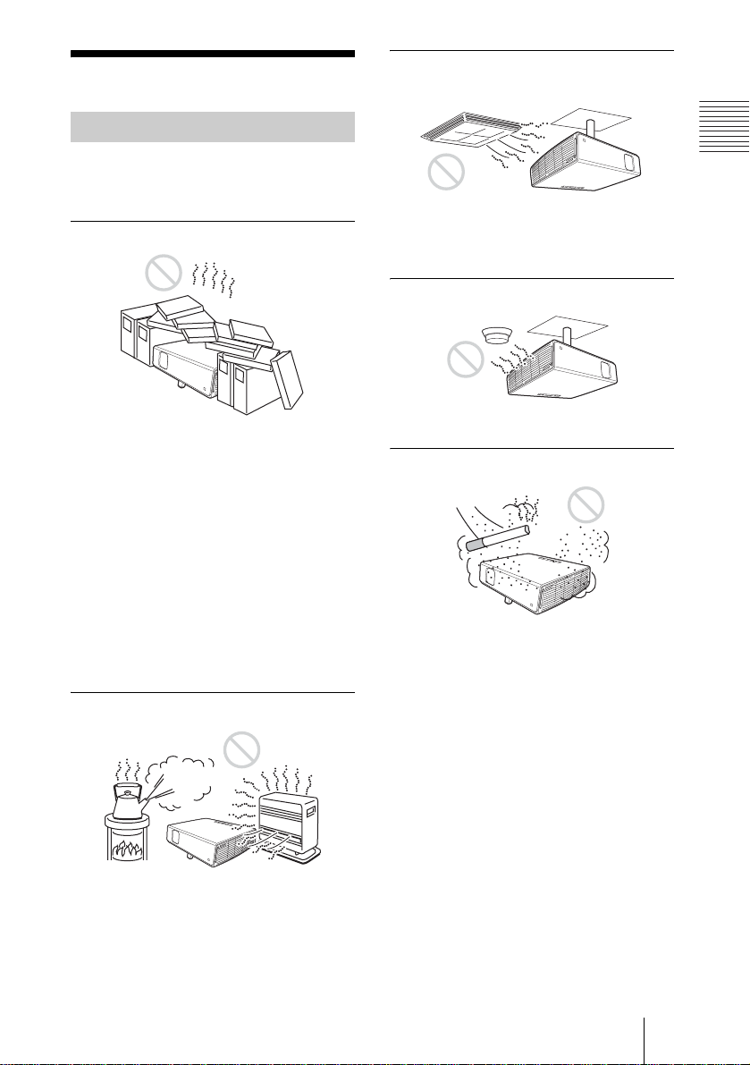
Poorly ventilated
• Allow adequate air circulation t o prevent
internal heat build-up. Do not place the
unit on surfaces (rugs, blankets, etc.) or
near materials (curtains, draperies) that
may block the ventilatio n holes. When the
internal heat builds up due to the block-up,
the temperature sensor will function with
the message “High temp.! Lamp off in 1
min.” The power will be turned off
automatically after one minute.
• Leave space of more than 30 cm (11
inches) around the unit.
• Be careful that the ventilation holes may
inhale tininess such as a piece of paper.
Highly heated and humid
7
/8
Subject to direct cool or warm air
from an air-conditioner
Installing in such a location may cause
malfunction of the unit due to moisture
condensation or rise in temperature.
Near a heat or smoke sensor
Malfunction of the sensor may be cause d.
Very dusty, extremely smoky
Avoid installing the unit in a very dusty or
extremely smoky environment . Otherwise,
the air filter will become obstructed, and this
may cause a malfunction of the unit or
damage it. Dust preventing the air passing
through the filter may cause a rise in the
internal temperature of the unit. Clean the
filter periodically.
Overview
• Avoid installing the unit in a location
where the temperature or humidity is very
high, or temperature is very low.
• To avoid moisture condensation, do not
install the unit in a location where the
temperature may rise rapidly.
Notes on Installation
GB
7
Page 8
Unsuitable Conditions Usage in High Altitude
Do not use the pr ojector unde r the follo wing
conditions.
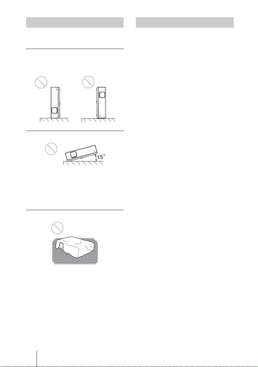
Toppling the unit
Avoid using as the unit topples over on its
side. It may cause mal function.
Tilting the unit to the right or left
Avoid tilting the unit to an angle o f 15°, and
avoid installi ng the unit in any way ot her
than placing on th e floor or susp ending fro m
the ceiling. Such installation may cause
color shading or shorten the lamp life
excessively.
When using the p rojector at an altitude of
1,500 m or higher, turn on “High
Altitude Mode” in the INSTALL SETTING
menu. Failing to set this mode when using
the projector at high altitudes could have
adverse effects, such as reducing
the reliability of certain components.
Note on carrying the projector
The unit is manuf actured using highprecision technology. When transporting the
unit stored in the carrying case, do not drop
the unit or subject it to shock, as this may
cause damage. When storing the unit in the
carrying c ase, disc onnect the AC power cord
and all other connecting cables or cards, and
store the supplied accessories in a pocket of
the carrying case.
Note on the screen
When using a screen with an uneven surface,
stripes pattern may rarely appear on the
screen depending on the distance between
the screen and the projector or the zooming
magnifications. This is not a m alfun c tio n of
the projector.
Blocking the ventilation holes
Avoid using a thick-piled carpet or anything
that covers the ventilation hole s (exhaust/
intake); otherwise, the internal heat may
build up.
For details on the ventilation holes (intake/
exhaust), see “Location and Function of
Controls” on page 12.
GB
8 Notes on Installation
Page 9

About the Supplied
Manuals
Names of Manuals
The following manuals are supplied with
this unit.
Operating Instructions (this manual)
The Operating Instruction describe the setup
and operations of this unit.
Note
It is necessary th at A dobe Acrobat Reader 5.0
or more is installed to read the Operating
Instructions co nt ai ned in the supplied CDROM.
Overview
Features
High brightness, high picture
quality
Operating Instructions for Memory
Stick (contained in the CD-ROM)
The Operating Instructions describe how to
view slides using the files stored in the
Memory Stick.
Operating Instructions for Air Shot
(contained in the CD-ROM)
The Operating Instructions describe how to
set up and operate the Air Shot.
PROJECTOR STATION for Air Shot
Help (contained in the CD-ROM)
This help describes how to operate the
PROJECTOR STATION for Air Shot
(Wireless connecting function) software.
Operating Instructions for USB
Storage Media
The Operating Instructions describe how to
use the USB storage Media.
USB Wireless LAN Module Utility
(contained in the CD-ROM)
The Operating Instructions describe how to
set up the USB Wireless LAN module.
PROJECTOR STATION for
Presentation Help (contained in the
CD-ROM)
The PROJECTOR STATION for
Presentation is an application software for
creating the files for a presentation
performed using the Memory Stick without
connecting a computer.
This help explai ns the configuration of the
PROJECTOR STATION for Presentation
windows and how to use it.
High brightness
Adopting Sony's unique new optical system
that incorporates newly dev eloped LCD
panels provides a high-efficiency optical
system. It allows the 190 W UHP lamp to
give a light output of 3000ANSI lumen.
High picture quality
Three super-high-aperture 0.79-inch XGA
panels with approximately 790,000-pixel
micro-lens array, produce a resolution of
1024 × 768 dots (horizontal/vertical) for
RGB input, and 750 horizontal TV lines for
video input.
Variety of network presentations
Air Shot feature incorporated
Air Shot features data transmission from a
computer to the projecto r via wireless LAN.
Use of the supplied wireless LAN card (for
the projector) and the USB wireless LAN
module (for a computer) enables a wireless
presentation.
A Simple Mode is also available without
setting up the network and wireless LAN
configurations, allowing you to start the
wireless presentation easily if y ou ar e usin g
the wireless LAN for the first time.
For details on the Air Shot feature, refer to
“Operating Instructions for Air Shot” and
“PROJECTOR STATION for Air Shot
Help” contained in the supplied CD-ROM.
About the Supplied Manuals
GB
9
Page 10

Presentation without connecting a
computer
Use of a Memory Stick enables you to run a
simple presentation without connecting a
computer.
“PROJECTOR STATION for Presentation”
software is supplied, allowing you to cr eat e
files for a presentation.
For more information, refer to “Operating
Instructions for Memory Stick” and
“PROJECTOR STATION for Presentation”
in Help.
Presentation tool with a laser pointer
The supplied presentation tool allows you to
use a laser pointer, or to advance a slide to
the next or previous page for your Air Shot
presentation.
Quiet presentation environment
Low fan noise is achieved and offen s i ve
sound to the ear is also reduced, allowing
you to run an optimum presentation even in
a quiet environment.
Easy setup and simple operation
Intelligent Auto-setup function
Simply press the power key, and the
projector automatically performs the setups
required before use. The projector opens the
lens protector, co r re c ts the V Keys to ne ,
detects a signal, and sets optimum
conditions for projection.
Powered zoom/focus equipped
The projector is equipped with a powered
zoom and powered focus lens, allowing you
to adjust the size and focus of an image with
the Remote Commander away from the
projector.
Side Shot
The projector supports the Side Shot feature
(horizontal trapezoidal corre ction functio n),
enabling projection from the side of the
screen. Installation availability becomes
wider.
Off & Go feature
The cooling fan built in the projector will
work even after turning the power off and
the power cord is disconnected. This enables
you to move th e projector t o another location
immediately after turning it off.
Versatile installation capability
Capable of floor, ceiling or tilt
installation
In addition to the front floor or ceiling
installation, you can install the projector by
tilting it 90 degrees at th e rear o r 90 de grees
in front.
Direct Power On/Off function
The AC power of the entire system can be
directly turned on/off with a breaker or other
switch without pressing the power key on
the projector.
System expandability using a
network
Connection to a wireless LAN allows you to
obtain projector status information such as
the lamp timer or to control the projector
away from the installation location via a
Web browser.
Short focal lens equipped
The projection dist ance is very short,
approximately 2.4 m (7.8 feet), when
projecting an 80-inch image, which allows
projection on a larger screen even in a
limited space.
GB
10 Features
Page 11

Security Functions
Security lock
This function makes it possi ble to project no
picture on the screen unless the required
password is entered when the projector is
turned on.
Panel key lock
This function lock s all the operation keys on
the control panel of the projector, allowing
use of the keys on th e Remote Comman der .
This prevents the projector from operating
incorrectly.
Overview
..............................................................................................................................................................
• Adobe Acrobat Reader is a trademark of Ad obe Systems Incorporated.
• Windows is a registered trademark of Microsoft Corporation in the United States and/or other
countries.
• VGA, SVGA, XGA and SXGA are registered trademarks of the International Business
Machines Corporation, U.S.A.
• Kensington is a register ed trademark of Kensington Technology Grou p.
• Macintosh is a registered trademar k of Apple Computer, Inc.
• VESA is a registered trademark of Video E lectronics Standard Association.
• Display Data Channel is a trademark of Video Electronics Standard Association.
• Memory Stick and are trademarks of Sony Corporation.
• Air Shot is trademark of Sony Corporat io n.
• Side Shot is trademark of Sony Corporat ion.
Features
11
GB
Page 12
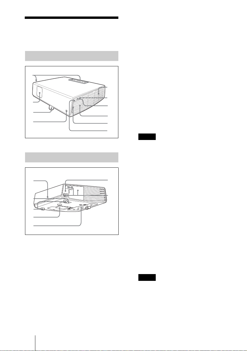
Location and
q
Function of Controls
Top/Front/Left Side
1
5
2
3
4
Rear/Right Side/Bottom
6
7
8
9
q;
Lights during access to the Memory
Stick.
Do not remove the Memory Stick while
the access lamp is lit.
7 Memory Stick slot
The Memory Stick can be inserted.
Never insert an object other than the
Memory Stick.
For details, see the attached “Operating
Instructions for Memory Stick” stored in
the CD-ROM.
8 Speaker
9 Wireless LAN card slot
The supplied wireless LAN card can be
inserted. Never inser t anything other
than the supplied wireless LAN card.
Notes
Remove the wireless LAN card from the
wireless LAN card slot when storing the
projector in th e carrying case.
For details, see Operating Instruction
for Air Shot (stored in the CD-ROM).
qa
qs
qd
qf
g
1 Control panel
For details, see “Control Pan e l ” on
page 13.
2 Lens protector (lens cover)
The lens protector automatically opens
when the power is turned on.
3 Powered tilt adjuster
4 Front remote control detector
5 Ventilation holes (exhaust)
6 Access lamp
GB
12 Location and Function of Controls
qh
qj
q; Wireless LAN card eject button
qa Rear remote control detector
qs Ventilation holes (intake)
qd Adjuster (hind pad)
Turn the adjuster to the right or left for
minor tilt adjustment of the projected
picture.
qf Ventilation holes (intake)/Lamp
cover
qg Ventilation holes (intake)/Air
filter cover
Notes
• Do not place anything near the
ventilation holes as this may cause
internal heat build-up.
• Do not place your hand or objects
near the ventilation holes as this may
cause a heat build-up.
• To maintain optimal performance , clean
the air filter every 1000 hours.
Page 13
For details, see “Cleaning the Air
Filter” on page 43.
qh Security lock
Connects to an optional security cable
(Kensington’s).
Web page address:
http://www.kensington.com/
qj Connector/Connector Panel
For details, see “Connector Panel” on
page 14.
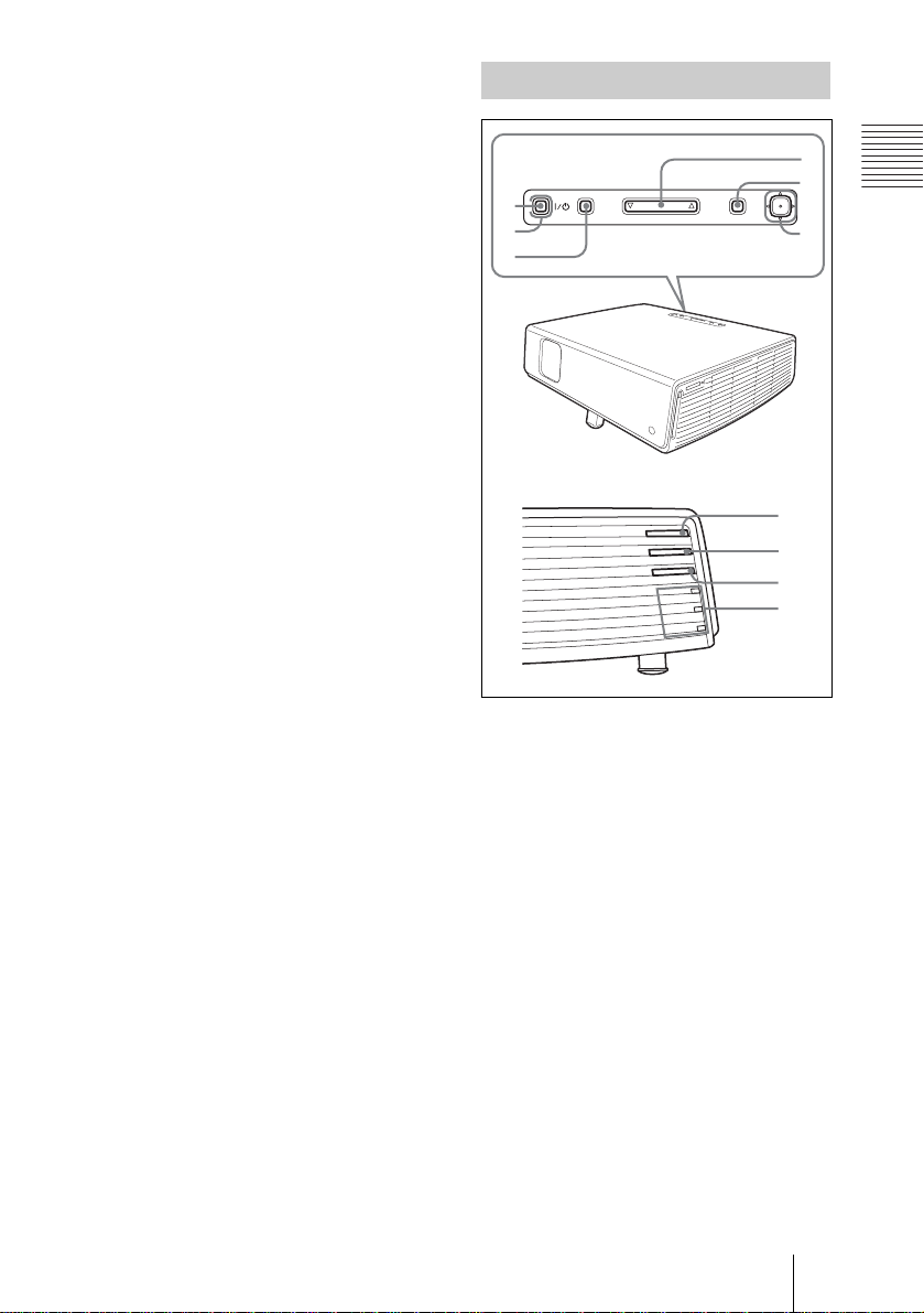
Control Panel
1
2
3
4
5
TILT
ENTER
PUSH
MENUINPUT
Overview
6
FOCUS
M
O
O
Z
T
O
SH
E
SID
BY
ND
A
ER ST
W
PO
N
/FA
MP
E
T
VER
P/CO
AM
L
7
8
9
0
1 I / 1 (on/standby) key
Turns on the projector when the
projector is in standby mode. The ON/
STANDBY indicator around the I / 1
key lights in green when the power is
turned on.
2 ON/STANDBY indicator (located
around the
I / 1 key)
Lights up or flashes under the following
conditions:
– Lights in red when an AC power cord
is plugged into a wall outlet. Once in
standby mode, you can turn on the
projector with the I / 1 key.
– Lights in green when the power is
turned on.
– Flashes in green while the coolin g fan
is running after the power is turned off
with the I / 1 key. The fan runs for
about 60 seconds after the power is
turned off.
Location and Function of Controls
13
GB
Page 14
For details on the I/1 indicators, see
page 25.
3 INPUT key
4 TILT adjustment key
For details, see “Projecting” on
page 23.
5 MENU key
Displays the on-screen menu. Press
again to clear the menu.
– Flashes when the lamp cover or air
filter cover is not secured firmly.
For details on the LAMP/COVER a nd
TEMP/FAN indicator, see page 47.
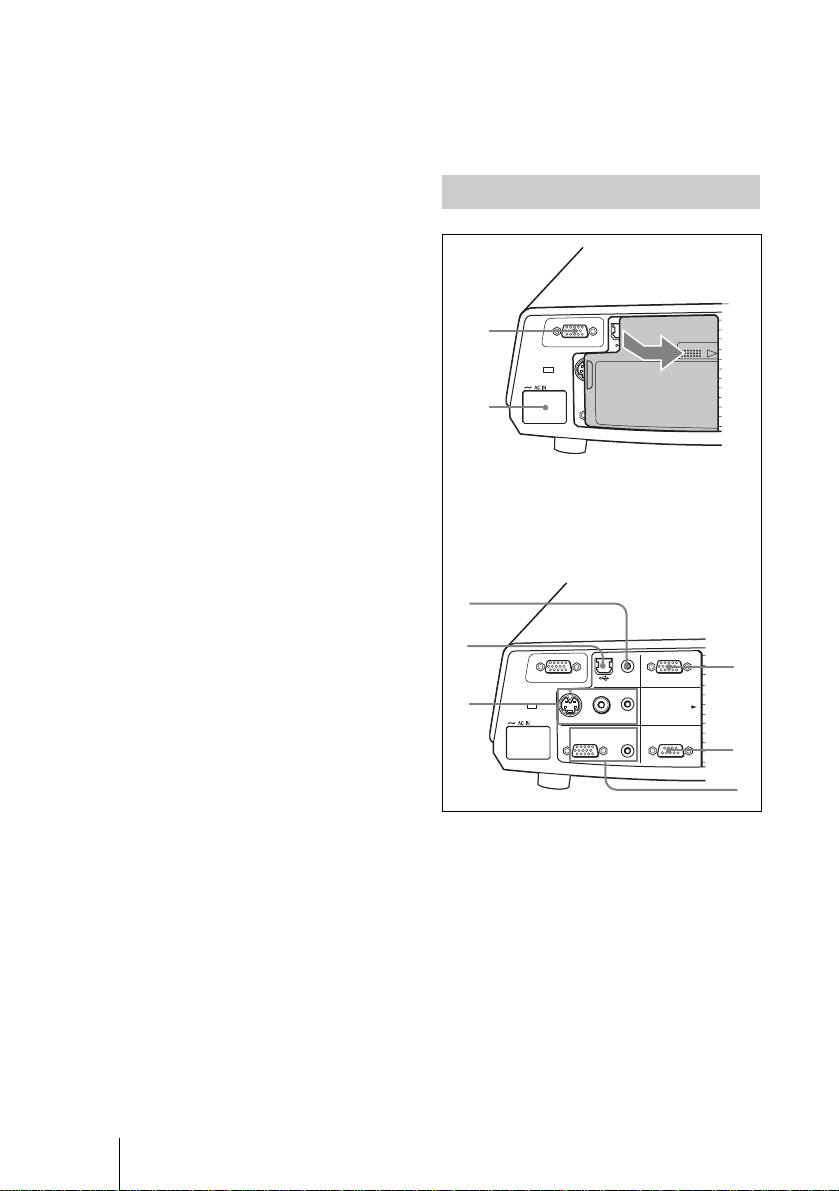
Connector Panel
6 ENTER/Arrow(f/F/g/G) keys
Enter the settings of items in the menu
system.
Select the menu or make various
adjustments.
7 FOCUS +/– keys
Adjusts the picture focus.
8 ZOOM +/– keys
Adjusts the picture size.
9 SIDE SHOT +/– key
Adjusts the horizontal trapezoidal
distortion/H keystone correction of the
picture.
For details, see “Side Shot” on page 39
and ““Side Shot” and “V Keystone”
Adjustments” on page 60.
q; Indicators
• POWER SAVING
Lights when the projector is in power
saving mode.
• TEMP (Temperature)/FAN
Lights or flashes under the following
conditions:
– Lights whe n t he t emperature inside
the projector becomes unusu al l y
high.
– Flashes when the fan is broken.
For details on the TEMP/FAN
indicator, see page 47.
• LAMP/COVER
Lights or flashes under the following
conditions:
– Lights when the lamp has reached
the end of its life or reaches a high
temperature.
GB
14 Location and Function of Controls
1
2
Open the cover when using the INPUT B or
VIDEO IN connector. To open the cover,
push the cover and slide it toward the right
until it locks.
To close the cover, press the cover to unlock
it and slide the cover toward the left.
INPUT A
VIDEO IN
VIDEOS VIDEO AUDIO
OUTPUT
AUDIO
AUDIOMONITOR
INPUT B
PUSH SLIDE
REMOTE RS-232C
3
4
AUDIO
INPUT B
INPUT A/B
INPUT A
5
S VIDEO
VIDEO IN
VIDEO
OUTPUT
AUDIO
AUDIOMONITOR
REMOTE
RS-232C
COVER
LOCK/UNLOCK
1 INPUT A connector (HD D-sub
15-pin, female)
Inputs a computer signal, video GBR
signal, component signal, or DTV signal
depending on eq uipment to be
connected.
Connects to the output connector of
equipment usin g the supplied ca ble or an
optional cable.
For details, see “Connecting with a
Computer” on page 20 and
“Connecting with a VCR” on page 22.
6
7
8
Page 15
2 AC IN socket
Connects the supplied AC po wer cor d.
3 AUDIO (stereo minijack)
connector (common INPUT A/B)
When listening to soun d output fro m the
computer, connect to the audio output of
the computer.
volume of the speakers can be
controlled by the VOLUME+/– keys
on the Remote Commander.
When INPUT A or B is selected, the
sound input to the AUDIO connector
which is common for INPUT A/B is
output.
Overview
4 USB connector (USB plug for
upstream, 4-pin)
Connect to the USB connector of a
computer. When you connect the
projector to the computer, you can
control the mouse function with the
supplied Remote Commander.
5 VIDEO IN (Video input)
connector
Connect to external video equipment
such as a VCR.
• S VIDEO (mini DIN 4-pin):
Connects to the S video output (Y/C
video output) of video equipment.
• VIDEO (phono type): Connects to
the composite vi deo output of vide o
equipment.
• AUDIO (stereo minijack): Connects
to the audio output of the VCR.
6 INPUT B connector (HD D-sub
15-pin, female)
Connect to external equipment such as a
computer.
Connects to the monitor output of a
computer using an optional cable.
7 RS-232C connector (D-sub 9-
pin, female)
Connects to a computer to operate the
projector from the computer.
8 OUTPUT connector (HD D-sub
15-pin, female)
• MONITOR: Connect to the video
input connector of t he mo nito r .
Outputs signals from the selected
channel and computer si gnals only
from among the signals from the
INPUT A or INPUT B.
• AUDIO (stereo minijack): Connects
to external active speakers. The
When the Memory Stick is selected in
INPUT C, the sound saved in the
Memory Stick is output.
When “Air Shot” is selected, no sound
is output.
When VIDEO or S VIDEO is selected,
the sound input to the AUDIO input
connector of VIDEO IN is output.
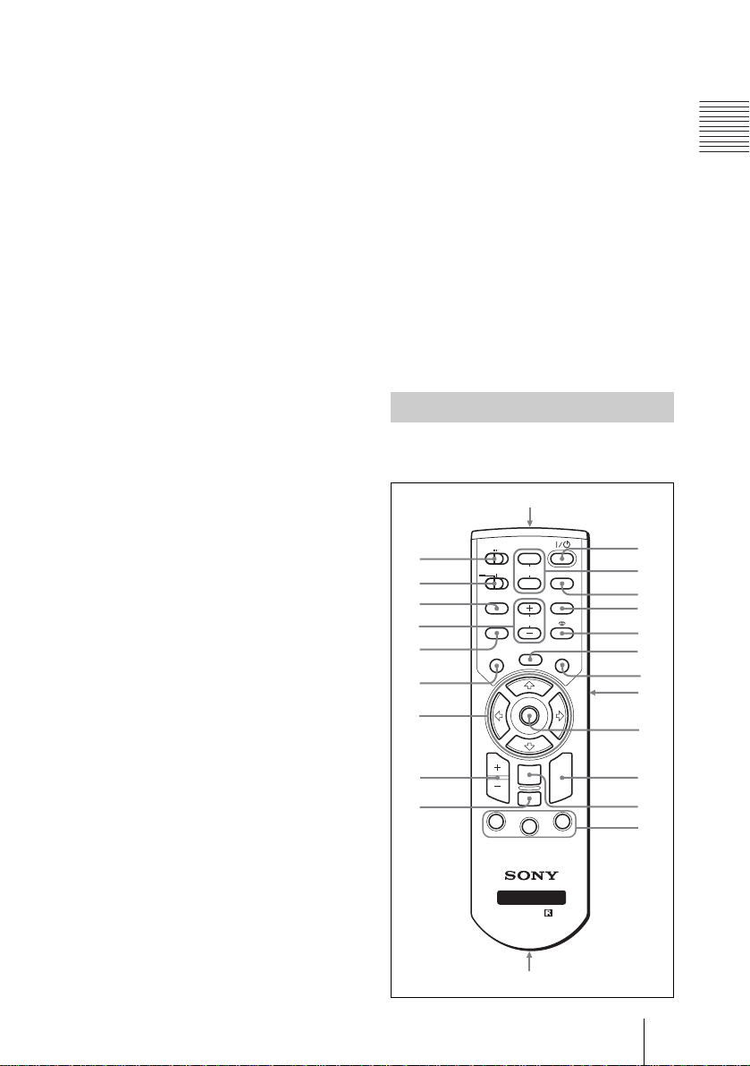
Remote Commander
The keys that have the same names as those
on the control panel function identically.
wa
COMMAND
OFF
w;
ql
qk
qj
qh
qg
qf
qd
qs
ON
PJ NETWORK
LENS
APA
MENU/
TAB
D ZOOM
1
PIC
MUTING
AUDIO
TILT/KEYSTONE
VOLUME
FREEZE
ENTER
RESET/
ESCAPE
2
FUNCTION
RM-PJM15
PROJECTOR
RM-PJM17
INPUT
AIR SHOT
R
CLICK
3
1
2
3
4
5
6
7
8
8
8
9
q;
a
b
c
qa
Location and Function of Controls
15
GB
Page 16

1 I / 1 (on/standby) key
2 MUTING keys
Cut off the picture and sound.
• PIC: Cuts off the picture. Press again
to restore the picture.
• AUDIO: Press to temporarily cut off
the audio output from the speaker, and
the output on the AUDIO jack in the
OUTPUT section. Press again or press
VOLUME + key to restore the sound.
8 Keys that emulate a mouse
These keys functi on as mouse buttons of
a computer only when the pr ojector is
connected to the computer using the
USB cable.
For details, see “Controlling the
Computer Using the Supplied Remote
Commander (When Using the USB
Cable)” on page 28.
9 ENTER key
3 INPUT key
4 TILT/KEYSTONE (Vertical/
horizonta l trapezoi dal distort ion
correction) key
Adjusts the tilt of the projector, or the
horizonal/vertical trapezoida l distortio n
of the image manually. Each time you
press this key, the Tilt menu, the V
Keystone menus and Side Shot menu are
displayed. Use the arrow keys (M/m/
</,) for adjustment.
5 (Memory Stick) key
Displays the Memory Stick Home.
When the input signal is other than
Memory Stick, it switches to Memory
Stick. When there are the files to be
displayed in the Memory Stick Home,
the slide show begins.
For details, see Operating Instructions
for Memory Stick (stored in the CDROM).
6 FREEZE key
Freezes the picture projected. To cancel
the frozen picture, press the key again.
7 AIR SHOT key
Displays the Air Shot Home.
When the input signal is other than Air
Shot, it switches to Air Shot.
When using the Air Shot, the list box of
the comput e r s th at ca n b e co nnected
appears.
For details on Air Shot, see Operating
Instruction for Air Shot (stored in the
CD-ROM).
q; FUNCTION 1, 2, 3 keys
These keys do not wo rk in this unit.
qa Strap holder
For attaching a strap.
qs RESET/ESCAPE key
Functions as a RESET key.
Resets the value of an item to its factory
preset value or returns the enlarged
image to its original size. This key
functions when the menu or a setting
item is displayed on the screen.
qd D ZOOM (Digital Zoom) +/– key
Enlarges the image at a desired location
on the screen.
qf Arrow keys (M/m/</,)
qg MENU/TAB key
Functions as a MENU key.
qh APA (Auto Pixel Alignment) key
Automatically adjusts a picture to its
clearest while a signal is input from a
computer.
For details on APA, see “ Smart APA” in
the SET SETTING menu on page 36.
qj VOLUME +/– keys
qk LENS key
Each time you press this key, Focus
adjustment menu and Zoom adjustment
menu are displayed alternat ely.
ql PJ/NETWORK (Projector/
Network) selector switch
Normally, set to “PJ”.
GB
16 Location and Function of Controls
Page 17
w; COMMAND ON/OFF switch
When this switch is set to OFF, no key
on the Remote Commander function.
This saves battery power.
wa Infrared transmitter
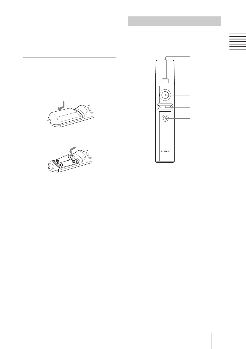
To install batteries
1 Push and slide to open the lid, then
install the two size AA (R6) batteries
(supplied) with the correct polarity.
While pressing the lid, slide it.
Be sure to install the battery
# side.
from the
2 Replace the lid.
Presentation Tool
When projecting the picture using the Air
Shot, you can control the presentation file
made by Microsoft Power P oin t .
1
LASER
2
SLIDE
B
3
4
1 Laser transmitter
2 LASER key
Emits a laser beam from the laser
transmitter while you keep this key
pressed.
Overview
3 SLIDE G/g key
Used to change pages of the slide show
in the forward/backward direction.
4 B key
This key corresponds to the “B” key of a
keyboard.
When you press this key during the slide
show, a black screen is displayed. To
cancel the black screen, press this key
again.
Location and Function of Controls
17
GB
Page 18
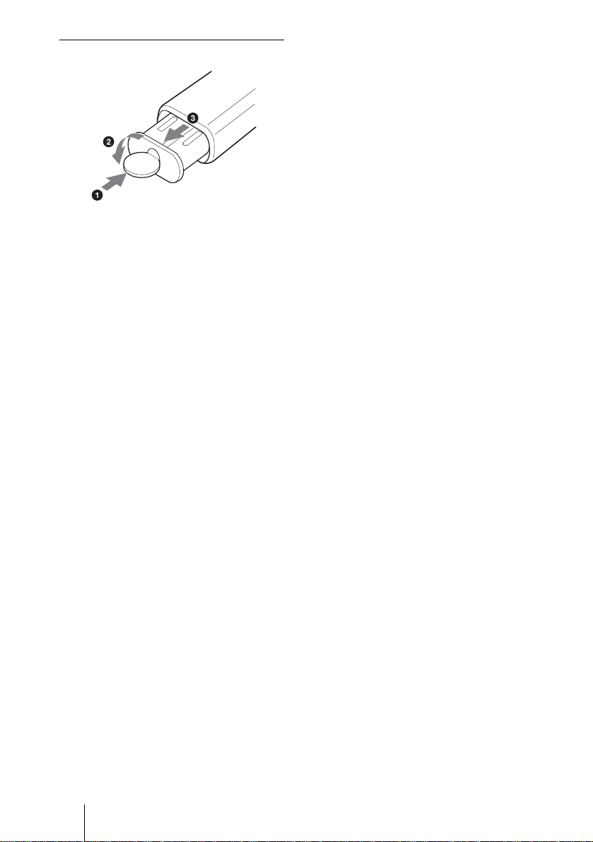
To install batteries
Open the cover (2) with a coin (1) and
remove the battery case (3). Install th e two
size AAA (R03) batteries with t he correct
polarity.
Notes on laser beam
• Do not look into the laser transmitter.
• Do not aim the laser at people.
Notes on Remote Commander/
Presentation tool operation
• Make sure that nothing obstructs the
infrared beam be tween the Remote
Commander/Presentatio n too l and the
remote control detector on the projector.
Direct the Remote Commander/
Presentation tool toward the front or rear
remote control detector.
• The operation range is limited. The shorter
the distance between the Remote
Commander/Presentatio n too l and the
projector is, the wider the angle within
which the commander can cont rol the
projector becomes.
GB
18 Location and Function of Controls
Page 19
B Setting Up and Projecting
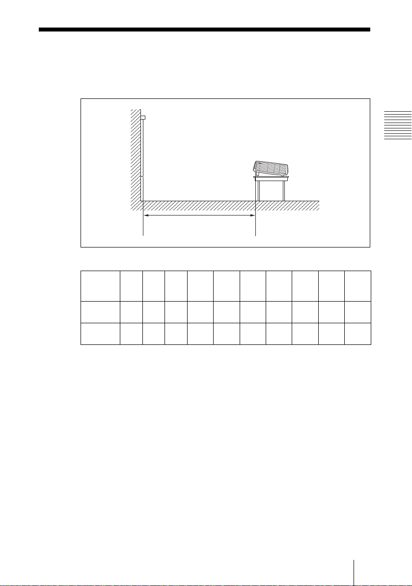
Installing the Projector
The distance between the lens and the screen varies depending on the size of
the screen. Use the following table as a guide.
Screen
Distance between the screen and
the center of the lens
Screen
size
(inches)
Minimum
Distance
Maximum
Distance
There may be a slight dif f erence between the act ual value and the design va lu e shown
in the table above.
40 60 80 100 120 150 180 200 250 300
1.2
1.8
2.4
3.0
(3.9)
1.4
(4.6)
(5.9)
2.0
(6.6)
(7.9)
2.7
(8.9)
(11.2)
(9.8)
3.4
3.6
(11.8)
4.1
(13.5)
4.5
(14.8)
5.2
(17.1)
5.4
(17.7)
6.2
(20.3)
6.0
(19.7)
6.9
(22.6)
Unit: m (feet)
7.5
8.7
9.0
(29.5)
10.4
(34.1)
(24.6)
(28.5)
Setting Up and Projecting
For details on installation, see “Installation Diagram” on page 56.
Installing the Projector
19
GB
Page 20
Connecting the
Projector
When you connect the projector,
make sure to:
• Turn off all equipment before making any
connections.
• Use the proper cables for each connection.
• Insert the cable plugs firmly; loose
connections may increase noise and
reduce performance of picture signals.
When pulling out a cable, be su re to pull it
out from the plug, not the cable itself
When connecting to a wireless L AN by using
the Air Shot, see “Operating Instructions for
Air Shot” contained in t he CD-ROM.
Connecting with a Computer
This section describes how to connect the
projector t o a co mputer.
For more information, refer to the
computer’s instru ction manual.
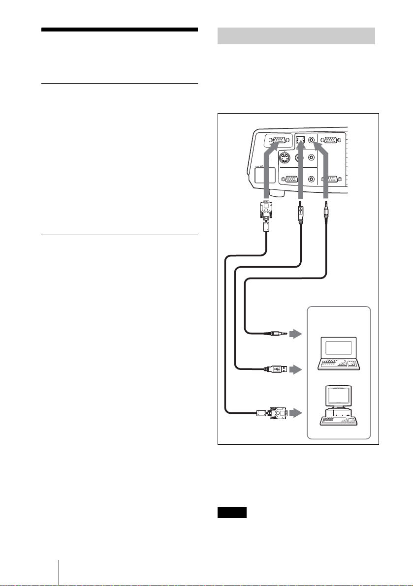
To connect a computer
Right side
INPUT B
VIDEO IN
VIDEOS VIDEO AUDIO
OUTPUT
AUDIO
AUDIOMONITOR
REMOTE RS-232C
INPUT A
To connect the projector, refer to
the illustrations on the next and the
following pages.
123
to audio output
to USB connector
to monitor output
1 Stereo audio connecting c able (not supplied)
(Use a no-resistance cable.)
2 USB cable (supplied)
(Connect the USB cable to use a wirele ss
mouse.)
3 HD D-sub 15-pin cable (supplied)
Notes
Computer
• The projector accepts VGA, SVGA, XGA,
SXGA and SXGA+ signals. However, we
recommend that you set the output mode of
GB
20 Connecting the Projector
Page 21

your computer to XGA mode for the ext ernal
monitor.
• If you set your computer, such as a notebook
type, to output the signal to both your
computer’s display and the external monitor,
the picture of the external monitor m ay not
appear properly. Set your computer to output
the signal to only the external monitor.
For details, refer to the computer’s
operating instructions supplied with your
computer.
On the USB function
When connecti ng the projector to a
computer by using the USB cable for the
first time, the computer re cognizes the
hu
man interface device (wireless mo use
USB
function) automatically.
Recommended operating
environment
When you use the USB function, connect the
USB cable as illustrated above. The USB
function can be used on a computer loaded
with Windows 98, Windows 98 SE,
Windows ME, Windows 2000 or Windows
XP preinstall models.
To connect a Macintosh computer
To connect a Macintosh computer equipped
with video output connector of a type having
two rows of pins, use a commercially
available plug adaptor. When you connect a
USB capable Macintosh computer using the
USB cable to the projector, wireless mouse
functions becom e available.
Setting Up and Projecting
Notes
• Your computer may not start correctly
when connected to the projector via the
USB cable. In this case, disconnect the
USB cable, restart the computer, then
connect the computer to the pro jector
using the USB cable.
• This projector is not guaranteed for
suspend, standby mode. When you use the
projector in susp end, standby mode ,
disconnect the projector from the USB
port on the computer.
• Operations are not guaranteed for all the
recommended computer env ironments.
•A Memory Stick inserted into the
Memory Stick slot on the projector cannot
be accessed from the PROJECTOR
STATION for Presentation.
Connecting the Projector
21
GB
Page 22

Connecting with a VCR
This section describes how to connect the
projector to a VCR.
For more information, refer to the
instruction manu als of the equipment you
are connecting.
To connect to a video or S video
output connector
Right side
INPUT B
VIDEO IN
VIDEOS VIDEO AUDIO
OUTPUT
AUDIO
AUDIOMONITOR
REMOTE RS-232C
INPUT A
To connect to a video GBR/
Component output
Right side
INPUT B
VIDEO IN
VIDEOS VIDEO AUDIO
OUTPUT
AUDIO
AUDIOMONITOR
REMOTE RS-232C
INPUT A
21
21
to audio
to S
video
output
output (L)
to video
output
VCR
1 Stereo audio connecting cable (not supplied)
(Use a no-resistance cable.)
2 Video cable (not supplied) or S-Video cable
(not supplied)
to audio
output
(R)
to
to video
GBR/
component
audio
output
(L)
output
VCR
1 Stereo audio connecting c able (not supplied)
(Use a no-resistance cable.)
2 SMF-402 Signal Cable
(not suppli e d)
HD D-sub 15-pin (male) ↔ 3 × phono jack
Notes
• Set the as pect ratio using “W ide Mode” in
the INPUT SETTING menu according to the
input signal.
• When you connect the projector to a video
GBR or component output connector, select
“Video GBR” or “Component” with the
“Input-A Signal Sel.” setting in the SET
SETTING menu.
• Use the composite sync signal when you
input the external sync signal from vide o
GBR/compon ent equipment.
to
audio
output
(R)
GB
22 Connecting the Projector
Page 23

Projecting
2
4
5
powered tilt adjuster rises and stops at
the previously adjusted position.
Note
When the projector is turned on, the
Startup screen is projected.
For details on the Startup screen, see the
attached “Operating Instructions for
PUSH
MENUINPUT
TILT
ENTER
Memory Stick” stored in th e CD-ROM.
ON/STANDBY indicators
Rear remote
control
detector
COMMAND
OFF
ON
PJ NETWORK
LENS
APA
MENU/
TAB
PIC
MUTING
AUDIO
VOLUME
FREEZE
INPUT
TILT/KEYSTONE
AIR SHOT
2
4
5
1 Plug the AC power cord into a wall
outlet, then connect all equipment.
The ON/STANDBY indicator lights in
red and the projector goes into standby
mode.
2 Press the I / 1 key.
The ON/STANDBY indicator lights in
green and the Intelligent Auto-setup
starts. The lens protector opens, and the
6
1
3 Turn on the equipment connected to
the projector.
4 Press the INPUT key to select the
input source.
Each time you press the key, the input
signal switches as follows:
INPUT-A t INPUT-B t INPUT-C t VIDEO t S-VIDEO
t
To input from Press INPUT to
Computer connected to
the INPUT A connector
Computer connected to
the INPUT B connecto r
Air Shot/Memory Stic k
(when you use the A ir
Shot/Memory Stick)
Video equipment
connected to the VIDEO
input connector
Video equipment
connected to the S VIDEO
input connector
Smart APA (Auto Pixel Alignment)
adjusts the picture of the conn ected
equipment so that it is pr ojected clearly.
Notes
• For INPUT C, input of the “Air Shot” or
“Memory Stick” can be switched by
selecting with the INPUT C selection
menu, or pressing the key or the
AIR SHOT key on the Remote
Commander. The Air Shot Home or the
Memory Stick Home is displayed on the
screen.
display
INPUT-A
INPUT-B
INPUT-C
VIDEO
S-VIDEO
Setting Up and Projecting
Projecting
23
GB
Page 24

• If “Auto Input Search” is set to “On,” the
projector searches for the signal s from
the connected equipment and displays
the input ch annel wher e the inpu t signals
are found.
For details, see “Auto Input Search”
on page 37.
• The Smart APA is effective for the input
signal from a com puter only.
5 Switch the equipment to be connected
to output to the projector.
Depending on the type of your
computer, for example a notebook, or an
all-in-one LCD type, you may have to
switch the computer to output to the
projector by pressing certain keys
(e.g., , etc.), or by
changing your computer’s settings.
VGA
LCD
//
,
To adjust using the control panel
Press f or F of the TILT key to adjust
the tilt of the projector.
to lower the
projector
TILT adjustment key
Powered tilt
adjuster
to raise the
projector
TILT
F7
or
Fx
and
Fn
6 Adjust the upper or lower position of
the picture.
To adjust using the Remote
Commander
Press the TILT/KEYSTONE key on the
Remote Commander to display the Tilt
menu and adjust the tilt using the M/m/
</, keys.
Notes
• When you adjust t he powered tilt
adjuster with the TILT key, the V
keystone adjustment is performed at the
same time. If you do not want to perform
the automatic keystone adjustment, set
the V Keystone menu to “Manual.” (See
page 39.)
• If you set the “V Keystone” adjustment
to “Auto,” the “V Keystone” correction
is automatically adjusted. However, it
may not be perfectly adjusted depending
on the room temperature or the screen
angle. In this case, adjust it manually.
• Press the TILT/KEYSTONE key on the
Remote Commander until “V Keystone”
appears on the scree n, and adjust the
value with the M/m/</, key. The
corrected value i s ef fective until the
power turn off.
• Be careful not to let the projector down
on your fingers.
• Do not push hard on the top of the
projecto r with the po wered tilt adjuster
out.
It may be occurred malfunction.
7 Adjust the horizontal trapezoidal
distortion ( )of the picture with
the “Side Shot.”
GB
24 Projecting
Page 25

To adjust using the Remote
Commander
Press the TILT/KEYSTONE key on the
Remote Commander to displa y the Side
Shot menu (horizontal trapezoi dal
distortion/H keystone correction) and
adjust the tilt using the M/m/</,
keys.
To adjust using the control panel
Press the SIDE SHOT +/ – key on the
control panel to adjust the distortion.
For details, see ““Side Shot” and “V
Keystone” Adjustments” on page60.
8 Adjust the size of the picture and the
focus.
To adjust using the Remote
Commander
Select the item to be adjusted by
pressing the LENS key, then adjust with
the M/m/</, key. Each time you
press the key, the menu changes t o
LENS FOCUS and LENS ZOOM in
order.
To adjust using the control panel
Press the ZOOM +/– keys on the
projector to adjust the size of the picture
and press the FOCUS+/– keys to adjust
the focus.
light up again the ON/STANDBY
indicator with the I / 1 key.
3 Unplug the AC power cord fro m the
wall outlet after the fan stops running
and the ON/STANDBY indicator
lights in red.
When you cannot confirm the onscreen message
When you cannot con firm the on-screen
message in a certain condition, you can turn
off the power by holding the I/ 1 key for
about two seconds instead of steps 1 and 2.
Note
• The internal circuitry of the Of f & G o and
Direct Power On/Off functions may cause
the fan to continue to operate for a short ti me
even after the I /
the power and the ON/STANDBY indicator
changes to red.
1 key is pres sed t o t ur n o ff
Setting Up and Projecting
Turning Off the Power
1 Press the I / 1 key.
“POWER OFF? Please press I / 1 key
again.” appears to confirm that you want
to turn off the power.
Notes
A message disappears if you press any key
except the I / 1 key, or if you do not press
any key for five secon ds.
2 Press the I / 1 key again.
The lens protector close and the powered
tilt adjuster is put away in the projector.
The ON/STANDBY indicator flashes in
green and the fan continues to run for
about 60 seconds to reduce the internal
heat. Also, the ON/STANDBY indicator
flashes quickly for the first 45 seconds.
During this time, you will not be able to
Projecting
25
GB
Page 26

B Convenient Function
Selecting the Menu
Language
You can select one of thirteen languages for
displaying the me nu and other on-scree n
displays. The factory setting is English.
To change the menu language, proceed as
follows:
3 Press the MENU key.
The menu appears.
The menu presently selected is shown as
a yellow button.
PICTURE SETTING
Picture Mode: Standard
Adjust Picture...
Volume: 30
Input A
2
ON/STANDBY indicators
1
COMMAND
OFF
ON
PJ NETWORK
MUTING
AUDIO
LENS
VOLUME
APA
MENU/
TAB
FREEZE
PIC
TILT
INPUT
TILT/KEYSTONE
AIR SHOT
4,5,6
3
PUSH
MENUINPUT
ENTER
Front remote
control
detector
2
3
4,5,6
4 Press the M or m key to select the
MENU SETTING menu, then press
the , or ENTER key.
The selected menu appears.
Input A
:
:
:
:
A
5 Press the M or m key to select
“Language,” then press the , or
ENTER key.
:
:
:
:
Input A
1 Plug the AC power cord into a wall
outlet.
2 Press the I / 1 key to turn on the
projector.
GB
26 Selecting the Menu Language
6 Press the M, m, < or , key to select
a language, then press the ENTER
key.
The menu changes to the selected
language.
To clear the menu
Press the MENU key.
The menu disappears automatically if a key
is not pressed for one mi nute.
Page 27

Security Lock
The projector is equipped with a security
lock function. When you turn the power of
the projector on, you are required to input
the previously set password. If you do not
input the correct password, you will not be
able to project the picture.
Note
You will not be able to use the pro jector if you
forget your password and the password
administrat or i s no t a vai l able . B e p lea se aw are
that using the se curity lock can prevent valid
usage in suc h cases. It is reco m mended that
you make a note of the selected password.
Next, the screen for entering the new
password is displayed. (Enter the
password at this screen even if you want
to keep the current password.)
Enter new password key.
Power-on cannot be performed
without the password.
Use: Cancel: Other key
3 Enter the password again to confirm.
Re-enter new password key.
Convenient Function
To use the security lock
1 Press the MENU key and then, in the
INSTALL SETTING menu, turn on
“Security Lock” setting.
the
2 Enter the password.
Use the MENU, M/m/</,, and
ENTER keys to enter the four-digit
password. (The default initial password
setting is “ENTER, ENTER, ENTER,
ENTER”. After this is entered you can
put in your own pass word. Therefore
when you use this function for the first
time, please input “ENT ER” four times.)
Enter password key.
Password required for power-on.
Use: Cancel: Other key
Be sure to remember this password.
Use: Cancel: Other key
When the following message is
displayed, the setting for sec urity lock is
completed.
INSTALL SETTING
Tilt...
V Keystone: Auto
Side Shot: 0
Image Flip: Off
Background: Blue
Test Pattern: Off
Lamp Mode: Standard
Lens Control: On
Direct Power On: Off
High Altitude Mode
Security Lock: On
Security Lock enabled!
: Off
Input-A
X
If “Invalid Password!” is displayed on
the menu screen, perform again from
step 1.
INSTALL SETTING
Tilt...
V Keystone: Auto
Side Shot: 0
Image Flip: Off
Background: Blue
Test Pattern: Off
Lamp Mode: Standard
Lens Control: On
Direct Power On: Off
High Altitude Mode
Security Lock: Off
Invalid Password!
: Off
Input-A
X
Security Lock
27
GB
Page 28
4 Turn the main power off and
disconnect the AC power cord.
The security lock is set to on, then it
becomes effective. The screen for
entering the password is displayed whe n
the power is turned on the next time.
Security certification
When the screen for entering the password is
displayed, enter the password that was set. If
you fail to enter the correct password after
three tries, the projector cannot be used. In
this case, press the I / 1 key to turn off the
power.
To cancel the security lock
1 Press the MENU key, then turn off the
“Security Lock” setting in the
INSTALL SETTING menu.
2 Enter the password.
Enter the password that was set.
Note
If you call the customer service ce nter
because you have forgotten the password,
you will need to be able to verify the
projector’s se rial nu mber an d your ide ntity.
(This process may differ in other countries.)
Once your identity has been confirmed, we
will provide you with the password.
• Smart APA (Auto Pixel Alignment)
Set “Smart APA” in the SET SETTING
menu to “Off.”
• Auto Input Search
Set “Auto Input Search” in the SET
SETTING menu to “Off.”
For details on the menu operations, see
“Using the MENU” on page 31.
Controlling the Computer
Using the Supplied Remote
Commander (When Using the
USB Cable)
When you connect a com puter to the
projector by usi ng the US B ca ble , yo u ca n
control the mouse of the computer using the
Remote Commander.
The R/L CLICK keys and joystick function
as follows.
Key and joystick Function
R CLICK (front) Right button
L CLICK (rear) Left button
Joystick Corresponds with the
movements of the
mouse
For details on USB connection, see “To
connect a computer” on page 20.
Other Functions
Switching from the Intelligent
Auto-setup Function to
Manual Adjustments
You can switch the following functions of
the Intelligent Auto-setup to manual
adjustments using the men u.
V Keystone correction (correction
•
of trapezoidal distortion)
Set “V Keys tone” in the INSTALL
SETTING menu to “Manual.”
GB
28 Other Functions
Note
Make sure that nothing obstructs the infrared
beam between the Remote Commander and th e
remote contro l detector on the projector.
Controlling the Computer
Using the Supplied
Presentation Tool (When
Using the Air Shot)
When you are using the Air Shot to project
the picture from a computer, you can
perform some operations for a slide show
using the supplied presentation tool. The
following keys on the pre s e ntation tool are
usable.
Page 29

Key Function
LASER Emits a laser beam.
G SLIDE g Changes the slides in
the forward/b a ckward
direction.
B Displays/cancels a
black screen during the
slide show.
* Als o available when not us in g t he Air Shot.
*
certain time even after the power cord is
removed.
Note
However, if the un it has been on for less than
15 minutes, the fan might not begin to turn as a
result of inadequate charging. In that case,
follow the procedure for turning off the power
as described in “Turning Off the Power” on
page 25.
Note
If there is any obstruction between the
presentation tool and the remote control
detector on the projector, the presentation tool
may not function properly.
Off & Go Function
If you are leaving the conference room
immediately, turn the proje ctor off, and then,
after the lens protector closes and the
powered tilt adjuster is put away in the
projector, you can unplug the AC power
cord. After the AC power cord is unplugged,
the fan runs automatically.
Notes
• When unplug ging the A C power cord , ensure
that the lens protector closes and the powered
tilt adjuster is put away in the projector.
Moving the projec t or with the powered ti l t
adjuster rised may damage the adjust er.
• Turn off the projector according t o the
procedure in “Turning off the power”, then
cool it down when storing the projector in the
carrying case.
Direct Power On/Off Function
Effective Tools for Your
Presentation
To enlarge the image (Digital Zoom
function)
You can select a point in the image to
enlarge. This function works when a signal
from a computer is input, or when a sti ll
picture (except a movie pict ure) stored in a
Memory Stick is projected.
This function does not work when a video
signal is input.
1 Project a normal image, and press the
D ZOOM + key on the Remote
Commander.
The digital zoom icon appears in the
center of the image.
Digital zoom
icon
2 Move the icon to the point on the
image you want to enlarge. Use the
arrow key (M/m/</,) to move the
icon.
Convenient Function
If you will be using a circuit breaker to turn
the power for the entire system on and off,
set the direct power on function to “On.”
When you turn off the power, you can also
just unplug th e po we r cord wit ho ut pre ss ing
the I / 1 key. The internal circuitry will
cause the fan to automatic al ly operate for a
3 Press the D ZOOM + key again.
The image where the icon is located is
enlarged. The enlargement ratio is
displayed on the screen for a few
seconds.
By pressing the + key repeatedly, the
image size increases (ratio of
enlargement: max. 4 times.)
Other Functions
29
GB
Page 30

Use the arrow key (M/m/</,) to
scroll the enlarged image.
To return the image back to its
original size
Press the D ZOOM – key.
Just pressing the RESET key returns the
image back to its original size imm edia tely.
To freeze the image projected
(Freeze function)
Press the FREEZE key. “Freeze” appears
when the key i s pressed. This function wo rks
when a signal from a compu t e r is i nput or
when a still picture stored in a Memory
Stick is projected.
To restore the original screen, press th e
FREEZE key again.
GB
30 Other Functions
Page 31

B Adjustments and Settings Using the Menu
1 Press the MENU key.
Using the MENU
The projector is equipped with an on-screen
menu for making various adjustments and
settings. The setting items are displayed in a
pop-up menu or in a sub menu. If you select
an item name foll owed by dots (...), a s ub
menu with setting items appear. You can
change the tone of the menu display and the
menu languag e displayed in the on-screen
menu.
To change the menu language, see
“Selecting the Menu Languag e” on page 26.
Display items
Input signal indicator
The menu appears.
The menu presently selected is shown as
a yellow button.
SET SETTING
Smart APA: On
Auto Input Search:
Input-A Signal Sel.:
Input-C Select: Air Shot
Color System: Auto
Speaker: On
Stand-by Mode: Standard
Power Saving: Off
IR Receiver: Front & Rear
Illumination: On
Panel Key Lock: Off
2 Use the M or m key to select a menu,
then press the , or ENTER key.
The selected menu appears.
3 Select an item.
Video
NTSC 3.58
Input signal setting indicator
Picture adjustment menu
Contrast
Input signal indicator
Shows the selected input ch annel. is
x
displayed when no signal is input. You can
hide this indicator using “Status” in the
MENU SETTING menu.
Input signal setting indicator
For Input A: Shows “Computer,”
“Component” or “Video GBR.”
For Input C: Shows “Air Shot” or
“Memory Stick”
For Video/S Video input: Shows “Auto” or
the “Color System” setting in the SET
SETTING menu.
Use the M or m key to select the item,
then press the , or ENTER key.
The setting items are displ ayed in a po pup menu or in a sub menu.
Pop-up menu
Setting items
Menu
MENU SETTING
Status:
Language:
Menu Position:
Menu Color:
Sub menu
Menu Setting items
PICTURE SETTING
ADJUST PICTURE
Contrast: 80
Brightness: 50
Gamma Mode: Graphics
Color Temp: High
Off
Computer
Selected input
signal
On
English
Top left
Bottom Left
Center
Top Right
Bottom Right
Standard
Input-A
Adjustments and Setting s Using the Menu
Input A
A
Input A
Using the MENU
31
GB
Page 32

4 Make the setting or adjustment on an
item.
• When changing the adjustment
level:
To increase the number, press the
, key.
To decrease the number, press the m
or < key.
Press the ENTER key to rest ore the
previous screen.
• When changing the setting:
Press the M or m key to change the
setting.
Press the ENTER or < key to restore
the previous screen.
When setting the Menu Language, see
“Selecting the Menu Language” on page 26.
To clear the menu
Press the MENU key.
The menu disappears automatically if a key
is not pressed for one minute.
To reset items that have been
adjusted
Press the RESET key on the Remote
Commander.
“Complete!” appears on the scree n and the
settings appearing on the screen are reset
to their factory preset values.
Items that can be reset are:
• “Contrast,” “Brightness,” “Color,” “Hue”
and “Sharpness” in the Adjust Picture...
menu.
• “Dot Phase,” “H Size,” and “Shift” in the
Adjust Signal... menu
M or
About the menu display
You can set the display position of the m enu,
intensity of the ba ckgrou nd pict ure and tone
of the menu items as you like.
For details, see “The MENU SETTING
Menu” on page 38.
About the memory of the settings
The settings are automatically stored in the
projector memory.
If no signal is input
If there is no input signal, “Cannot adjust
this item.” appears on the screen.
GB
32 Using the MENU
Page 33

The PICTURE
SETTING Menu
The PICTURE SETTING menu is used for
adjusting the picture or volume.
Items that cannot be adjusted depending on
the input signal are not displayed in the
menu.
For details on th e unadjustable items, see
page 52.
Adjust Picture...Menu Items
When the video signal is input
PICTURE SETTING
ADJUST PICTURE
Contrast: 80
Brightness: 50
Color: 50
Hue: 50
Sharpness: Middle
Color Temp.:
Standard
Low
Video
PICTURE SETTING
Picture Mode Standard
Adjust Picture...
Volume: 30
Input A
Menu Items
Picture Mode
Selects the picture mode.
Dynamic: Emphasizes the contrast to
produce a “dynamic” picture.
Standard: Normally select this setting. If
the picture has rough ness with the
“Dynamic” setting, this setting reduces
the roughness.
Volume
Adjusts the volume.
Adjust Picture...
The unit can store the setting val ues of the
following sub menu items for each
“Dynamic” or “S ta nd ard” picture mode
separately.
When the computer signal is input
PICTURE SETTING
ADJUST PICTURE
Contrast: 80
Brightness: 50
Gamma Mode: Graphics
Color Temp.: High
Standard
Input A
Contrast
Adjusts the picture contrast. The higher the
setting, the greater the contrast between a
dark portion and a bright portion of the
picture. The lower the setting, the lower the
contrast.
Brightness
Adjusts the picture brightness. The higher
the setting, the brighter the picture. The
lower the setting, the darker the picture.
Color
Adjusts color intensity. The higher the
setting, the greater the intensity. The lower
the setting, the lower the intensity.
Hue
Adjusts color tones. The higher the setting,
the picture becomes greenish. The lower the
setting, the picture becomes purplish.
Adjustments and Setting s Using the Menu
The PICTURE SETTING Menu
33
GB
Page 34

Sharpness
Selects the picture sharpness from among
“High,” “Middle” and “Low.” The “High”
setting makes the picture sharp; the “Low”
setting makes it soft.
Gamma Mode
Selects a gamma correction curve.
Graphics: Improv es the reproduction of
halftones. Pho tos can be reproduced in
natural tones.
Text: Contrasts black and white. Suitable
for images that contain lots of text.
Color Temp.
Adjusts the color temperature.
High: Makes the white color bluish.
Low: Makes the white color reddish.
The INPUT SETTING
Menu
The INPUT SETTING menu is used to
adjust the input signal.
Items that cannot be adjusted depending on
the input signal are not displayed in the
menu.
For details on the unadjustable items, see
page 52.
When the video signal is input
INPUT SETTING
Wide Mode: Off
When the computer signal is input
INPUT SETTING
Adjust Signal...
Scan Converter: On
Video
Input A
GB
34 The INPUT SETTING Menu
MENU Items
Wide Mode
Sets the aspect ratio of the picture. When
inputting 16:9 (squeezed) signal from
equipment s uch as a DVD player , set to
“On”.
Off: When the picture with ratio 4: 3 is input.
On: When the picture with ratio 16:9
(squeezed) is input.
Page 35

Note
Note that if the projector is used for profi t or for
public viewing, modifying the original picture
by switching to the wide mode may constitute
an infringement of the rights of authors or
producers, which are legally protected.
Adjust Signal... Menu Items
(Only when the computer signal is
input)
INPUT SETTING
SIGNAL SETTING
Dot Phase: 24
H Size: 1504
Shift: H: 181 V: 34
Input A
key to adjust the horizontal position and the
M and m key for the vertical position.
Scan Converter
Converts the signal to display the p icture
according to the screen size.
On: Displays the picture according to the
screen size. The picture will lose some
clarity.
Off: Displays the picture while matching
one pixel of input picture ele ment to that
of the LCD. The picture will be clear but
the picture size will be smaller.
Note
When XGA, SXGA or SXGA+ signal is input,
this item will not be displayed.
Dot Phase
Adjusts the dot phase of the LCD panel and
the signal output from a computer.
Adjust the picture further for finer picture
after the picture is adjusted by pressing the
APA key.
Adjust the picture to where it looks clearest.
H Size
Adjusts the horizontal size of picture output
from a connector. The higher the setting, the
larger the horizontal size of the picture. The
lower the setting, the smaller the horizontal
size of the picture. Adjust the setting
according to the dots of the input signal.
For details on the suitable value for the
preset signal s, se e pa ge 53.
Shift
Adjusts the position of the pi cture. H adjusts
the horizontal position of the picture.V
adjusts the vertical position of the picture.
As the setting for H increases, the picture
moves to the right, and as the setting
decreases, the picture moves to the left.
As the setting for V increases, the picture
moves up, and as the setting decreases, the
picture moves down. Use the < or the ,
About the Preset Memor y No.
This projecto r has 45 types of pr eset dat a for
input signals (the preset memory). When a
preset signal is input, the projector
automatically detects the signal type and
recalls the data for the signal from the preset
memory to adjust it to an optimum picture.
The memory number and signal type of that
signal are displayed in the INFORMATION
menu (See page 40). You can also adjust the
preset data through the INPUT SETTING
menu.
This projector has 20 types of user memories
for INPUT-A into which you can save the
setting of the adjusted data for an unpreset
input signal.
When an unpreset signal is input for the first
time, a memory number is displayed as 0.
When you adjust the data of the signal in the
INPUT SETTING menu, it will be
registered to the proj ector. If more than 20
user memories are registered, the newest
memory always overwrites the oldest one.
See the chart on page 53 to find if the signal
is registered to the preset memory.
Adjustments and Setting s Using the Menu
The INPUT SETTING Menu
35
GB
Page 36

Since the data is recalled from the preset
memory about the following signals, you
can use these preset data by adj usting “H
Size.” Make fine adj ustment by adjusting
“Shift.”
Signal Memory No. SIZE
Super Mac-2 23 1312
SGI-1 23 1320
Macintosh 19 " 25 1328
Macintosh 21 " 27 1456
Sony News 36 1708
PC-9821
36 1600
1280 × 1024
WS Sunmicro 3 7 1664
The SET SETTING
Menu
The SET SETTING menu is used for
changing the settings of the projector.
SET SETTING
Smart APA: On
Auto Input Search:
Input-A Signal Sel.:
Input-C Select: Air Shot
Color System: Auto
Speaker: On
Stand-by Mode: Standard
Power Saving: Off
IR Receiver: Front & Rear
Illumination: On
Panel Key Lock: Off
Off
Computer
Input-A
Note
When the aspect ratio of input signal is other
than 4:3, a part of the screen is displayed in
black.
Menu Items
Smart APA
Activates or deactivates the Smart APA
On: Normally select this setting. When a
signal is input from a c omputer, the APA
functions automatically so that the
picture can be seen clearly. Once the
specified input signal has been adjusted
by the “Smart APA,” it will not be
readjusted even when the cable is
disconnected and connected again or the
input channel is changed. You can adjust
the picture by pressi ng APA key on the
Remote Commander even if the “Smart
APA” set to “On.”
Off: The APA functions when you press the
APA key on the Remote Commander.
Notes
• Press the APA k e y when the full image is
displayed on the scr een. If the projected
image includes much black portion around it,
the APA function will not work properly and
some parts of the image may not be displayed
on the screen.
• You can c ancel the adjustment by pressing
the APA key again w hile “Adjusting”
appears on the scre en.
• The pictu re m ay not be adjusted properly
depending on the kinds of input signals.
1)
.
GB
36 The SET SETTING Menu
Page 37

• Adjust the items “D ot Phase,” “H Size” and
“Shift” in the INPUT SETTING menu when
you adjust the picture manually.
1)The APA (Auto Pixel Alignment)
automatica lly adjusts “Dot Phase ,” “H Size”
and “Shift” in the INPUT SETTING menu
for the input signa l f ro m a computer.
Auto Input Search
Normally set to “Off.”
When set to “On,” the projector detects input
signals in the following order: Input-A/
Input-B/Input-C/Video/S-Video. It indicates
the input channel when the power is turned
on or the INPUT key is pressed.
Input-A Signal Sel.
Selects the computer, component or video
GBR signal input fro m the INPUT A
connector.
Note
If the setting is not correct, the color of the
picture becom es st range or “Please che ck
Input-A Signal Sel.” appears on the screen and
the picture is not displayed.
Input-C Select
Select “Air Shot” or “ Memory Stick” as the
input source that you want to project in the
INPUT C.
Color System
Selects the color system of the input signal.
If you select “Auto,” the projector detects
the color system of the input signal
automatically. If the picture is distorted or
colorless, select the color system ac cording
to the input signal.
When the color system of the input signal is
PAL60, select “PAL.” If “Auto” is selected,
the color system cannot be detected.
Speaker
Set to “Off” to cut off the sound of the
internal speakers. When set to “Off,”
“Speaker: Off” appears on the screen when
you turn on the power.
Stand-by Mode
You can lower the power consumption in
standby mode .
Standard: Normally, select this position
when you use the Air Shot even in
standby mode.
Low: Select this position when you do not
use the Air Shot, and want to lower the
power consumption in standby mode.
Power Saving
When set to “On,” the projector goes into
power saving mode if no signal is input for
10 minutes. Although the lamp goes out, the
cooling fan keeps running. The power
saving mode is canceled when a sig nal is
input or any key is pressed. In power saving
mode, any key does not function for the first
60 seconds after the lamp goes out.
IR Receiver
Selects the remote control detectors (IR
receiver) on the front and rear of the
projector.
Front&Rear: Activates both the front and
rear detectors.
Front: Activates the front detector only.
Rear: Activates the rear detector only.
Illumination
Selects whether the SONY logo on the top
panel of the projector lights when the
projector is on. Normally, this setting is
“On”. If you want complete darkness or if
the illuminated logo is a distra c tion, change
this setting to “Off”.
Panel Key Lock
Locks all the control panel keys on the top
and side panels of the pr ojector so that the
projector can be operated only w ith the
Remote Commander.
To lock the control panel keys, set to “On.”
When it is set to “On,” keeping the I/1 key
on the control panel pr essed for 10 seconds
turns the projector on when it is in standby
mode, and turns the projector to stand by
mode when the power is on . If you keep
Adjustments and Setting s Using the Menu
The SET SETTING Menu
37
GB
Page 38

pressing the MENU key for about 10
seconds when the power is on, the lock will
be released and “Panel Key Lock” is
automatically set to “Off.”
The MENU SETTING
Menu
Note
The function can be controlled with the
REMOTE RS-232C connector.
The MENU SETTING menu is used for
changing the me n u dis p la ys .
MENU SETTING
Status: On
Language: English
Menu Position: Center
Menu Color: White
Input A
A
Menu Items
Status (on-screen display)
Sets up the on-screen display.
On: Shows all of the on-screen displays.
Off: Turns off the on-screen displays except
for the menus, a message when turning
off the power, and warning messages.
Language
Selects the language used in the menu and
on-screen displays. Available languages are:
English, Nederlands, Français, It al iano,
Deutsch, Español, Português, ,
Svenska, Norsk, , and .
GB
38 The MENU SETTING Menu
Menu Position
Selects the disp lay position of the me nu
from “Top Left,” “Bottom Left,” “Center,”
“Top Right” and “Bottom Right”.
Menu Color
Selects the tone of the menu display from
“Black” or “White”.
Page 39

The INSTALL
SETTING Menu
Side Shot
Corrects the horizontal trapezoidal
distortion of the picture using the < or ,
key on the Remote Commander.
The INSTALL SETTING menu is used for
changing the settings of the projector.
INSTALL SETTING
Tilt...
V Keystone: Auto
Side Shot: 0
Image Flip: Off
Background: Blue
Test Pattern: Off
Lamp Mode: Standard
Lens Control: On
Direct Power On: Off
High Altitude Mode
Security Lock: Off
: Off
Input-A
Menu Items
Tilt...
Adjusts the position (height) of the pro jected
picture. Pressing the f on the TILT
adjustment key o r M/, key on the Remote
Commander, the more the proje ctor tilts and
the higher the position of the picture.
Pressing the F on the TILT adjustment key
or m/< key on the Remote Commander,
the less the projector tilts and the lower the
position of the picture.
V Keystone
Corrects the trapezoidal distortion caused by
the projection angle. Select “Auto” for
automatic correction, or “Manual” for
manual correction using the < or , key.
When the bottom of the trapezoid is
longer than the top : Sets a lower
value.
When the top of the trapezoid is longer
than the bottom : Sets a higher
value.
Note
The auto V Keystone adjustment may not
correct the trapezoidal distortion perfectly,
depending on t he room temperature or the
screen angle.
When the right side is longer tha n the
left side ( )
Set to a higher value (+ direction).
When the left side is longer than the
right side ( )
Set to a lower value (– direction).
Set the adjustment level to “0” if you want t o
adjust the picture more widely using “V
Keystone” only.
Note
Even when projecting using “Side Shot”, the
four sides of a picture may sometimes not be
parallel to the respective sides o f a s creen
frame.
Adjustments and Setting s Using the Menu
Image Flip
Flips the image on the screen horizontally
and/or vertically.
Off: The image does not flip.
HV: Flips the image horizontally and
vertically.
H: Flips the image horizontally.
V: Flips the image vertically.
Background
Select the background col or of t he screen
when no signal is input to the projector.
Select “Black” or “Blue”.
Normally, set to “Blue.”
Test Pattern
The factory setting is “Off.”
When set to “On,” a test pattern is d isplayed
on the screen during the “Lens Zoom”
adjustment, “Lens Focus,” “Si de Shot” or
“V Keystone.” If you do not want to display
a test pattern, set to “Off”.
The INSTALL SETTING Menu
39
GB
Page 40

Lamp Mode
Sets the lamp brightness in the projection .
High: Illuminate s the project ed image
brightly.
Standard: Reduc e s f a n noise and power
consumption. The brightness of the
projected image will be lower compared
with the “High” setting.
Direct Power On
Set to “On” if you are using a circuit breaker
to turn the power on/off the entire system.
You can turn off the power just by
unplugging the power cord without pressing
the I/1 key.
Lens Control
When set to “Off,” the LENS (FOCUS,
ZOOM) key on the Remote Commander,
and the FOCUS and ZOOM keys on the
projector do not function.
High Altitude Mode
The factory setting is “Off.”
Set to “On” when the projector is used at an
altitude of 1,500 m or highe r .
Security Lock
Turns on the projector’s security lock
function.
Off: Turns off the security lock function.
On: Turns on the security lock function,
which locks the projector once a
password has been set.
For details, see “Security Lock” on page 27.
The INFORMATION
Menu
The INFORMATION menu displays the
horizontal and vertical frequencies of the
input signal and the used time of the lamp.
INFORMATION
fH: 48.47kHz
fV: 60.00Hz
No.23
1024x768
Lamp Timer: 0H
Menu Items
fH
Displays the horizontal frequency of the
input signal.
The displayed value is approximat e.
fV
Displays the vertical frequency of the input
signal.
The displayed value is approximat e.
Lamp Timer
Indicates how long the lamp has been tu rned
on.
Note
These only display on the screen. You cannot
alter the display.
Input A
Memory
number of
an input
signal
Signal
type
GB
40 The INFORMATION Menu
Page 41

B Maintenance
Maintenance
projector o v er so you can see its
underside.
Replacing the Lamp
Replace the lamp with a new one in the
following case.
• When the lamp has burnt out or dims
• “Please replace the LAMP.” app ears on
the screen
• The LAMP/COVER indicator lights up
The lamp life varies depending o n
conditions of use.
Use LMP-C190 Projector Lamp as the
replacement lamp.
Use of any other lamps than the LMP-C190
may cause damage of the projector.
Caution
The lamp becomes a high temperature after
turning off the projector with the I / 1 key. If
you touch the lam p, you may scald your
finger. When you replace the lamp, wait for
at least an hour for the lamp to cool.
Notes
• If the lamp breaks, consult with qualified
Sony personnel.
• Pull out the lamp by holding the handle. If
you touch the lamp, yo u m ay be burned or
injured.
• When removing the lamp, make sure it
remains ho rizontal, then pull s traight up. Do
not tilt the lamp. If you pull out the lamp
while tilted and if the lamp bre aks, the pieces
may scatter, causing injury.
Note
Be sure that the projector is stable after
turning it over.
3 Open the lamp cover by loosening a
screw with the Phillips screwdriver.
Note
For safety sake, do not loosen any other
screws.
Maintenance
1 Turn off the projector, and disconnect
the AC power cord from the AC
outlet.
Note
When replacing th e l am p after using the
projector, wait for at least an hour for the
lamp to cool.
2 Place a protective sheet (cloth)
beneath the projector. Turn the
Maintenance
41
GB
Page 42
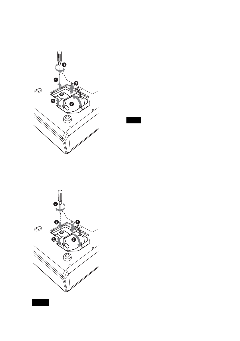
4 Loosen the two screws on the lamp
unit with the Phillips screwdriver
(1). Fold out the handle (2), then
pull out the lamp unit by the handle
(3).
Handle
5 Insert the new lamp all the way in until
it is securely in place (1). Tighten the
two screws (2). Hold down the
handle to replace (3).
• The power will not turn on if the lamp is
not secured prop er ly.
6 Close the lamp cover and tighten a
screw.
7 Turn the projector back over.
8 Connect the power cord.
The ON/STANDBY indicator around
the =/1 key lights in red.
9 Press the following keys on the
Remote Commander in the following
order for less than five seconds each:
RESET, <, ,, ENTER.
Note
Do not put your hands into the lamp
replacement spot, or not fall any liquid or
object into it to avoid elect ri cal shock or fire.
Disposal of the used lamp
For the custmers in the USA
This product contains mercury. Disposal of
this product may be regulated if sold in the
United Stat es . For disposal or r ec ycling
information, please contact yo ur loc a l
authorities or Electronics Industries Allianc e
(www.eiae.org http://www.eiae.org).
Notes
• Be careful not to touch the glass surface
of the lamp.
GB
42 Maintenance
Page 43

Cleaning the Air Filter
The air filter should be cleaned every 1000
hours.
Remove dust from the outside of the
ventilation holes with a vacuum clean e r.
1,000 hours are approximate. This value
varies depending on the en viromment or
how the projector is used.
When it becomes difficult to remove the dust
from the filter with a vacuum cleaner,
remove the air filter and wash it.
1 Turn off the power a nd unplug the
power cord.
2 Place a protective sheet (cloth)
beneath the projector and turn the
projector over.
3 Remove the air filter cover.
4 Remove the air filter.
5 Wash the air filter with a mild
detergent solution and dry it in a
shaded place.
6 Attach the air filter and replace the
cover.
Notes
• If you neglect to clean the air filter, dust
may accumulate, clogging it. As a result,
the temperature may rise inside the unit,
leading to a possible malfunction or fir e .
• If the dust cannot be removed fr om the air
filter, replace the air filter with the supplied
new one.
• Be sure to attach the air filter cover firmly;
the power will not be turned o n if it is not
closed securely.
• The air filter has a face and a re verse side.
Place the air filter so that it fits in a notch on
the air filter cove r.
Maintenance
Maintenance
43
GB
Page 44

Troubleshooting
If the projector appears to be operating erratically, try to diagnose and correct the problem
using the following instructions. If the problem persists, consult with qualified Sony
personnel.
Power
Symptom Cause and Remedy
The power is not turned on. • The power has been turned off and on with the I / 1 key at a short
Both the LAMP/COVER
and TEMP/FAN indicators
light up.
The powered tilt adjuster
and the lens protec to r do
not close.
The lens protector cannot
open.
interval.
c Wait for about 60 seconds before turning on the power
(see page 25).
• The lam p cove r i s de tached.
c Close the lamp cover securely (see page 41).
• The air filter cover is detached.
c Close the air filter cover securely (see page 43).
• The electrical system breaks down.
c Consult with qualified Sony personnel.
• The AC power cord is un plugged with the power of the projector
turned on.
c Connect the power cord to the AC outlet again, turn on the
power of the projector, then turn it off.
• The electrical system breaks down.
c Consult with qualified Sony personnel. If it is necessary to use
the projector in case of emergency, slide the lens protector by
hand, and then press th e I/
1 key. You can use the projecto r.
GB
44 Maintenance
Page 45
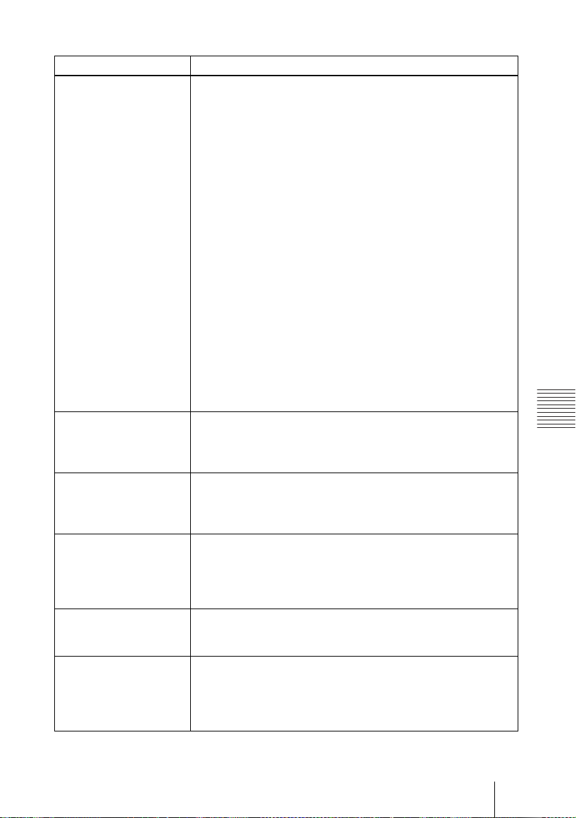
Picture
Symptom Cause and Remedy
No picture. • Cable i s di s connected or the connections are wrong.
The picture is noisy. • Noise may appear on the backgr ound depending on the
The picture from INPUT A
connector is col o r ed
strange.
“Please check Input-A
Signal Sel.” appears in
spite of inputting the
correct sig nal from INPUT
A.
On-screen display does not
appear.
Color balance is incorrect. • Picture has not been adjusted properly.
c Check that the proper connections have been mad e
(see page 20).
• The co nnections are wrong.
c This projector is compatible with a DDC2B (Digital Data
Channel 2B). If your computer is compatible with a DDC, turn
the projector on according to the following procedures.
1 Co nnect the projector to the com puter.
2 Turn the projector on.
3 Start the computer.
• Input selection is incorrect.
c Select the input source correctly using the INPUT key
(see page 23).
• The picture is muted.
c Press the PIC MUTING key to release the picture muting (see
page 16).
• A black screen is displayed.
c Press the B key on the presentation tool to release the black
screen (see page 17).
• The computer signal is not set to output to an external monitor or
set to output both to an external monitor and a LCD monitor of a
computer.
c Set the computer signal to output only to an external monitor
(see page 21).
combination of th e numbers of dot input fr om the connector and
numbers of pixel on the LCD panel.
c Change the desktop pattern on the connected computer .
• Setting of “Input-A Signal Sel.” in the SET SETTIN G me nu is
incorrect.
c Select “Computer,” “Video GBR” or “Component” correctly
according to the input signal (see page 37).
• Setting of “Input-A Signal Sel.” in the SET SETTIN G me nu is
incorrect.
c Select “Computer,” “Video GBR” or “Component” correctly
according to the input signal (see page 37).
• “Status” in the MENU SETTI NG me nu has been set to “Off.”
c Set “Status” in the MENU SETTING menu to “On” (see page
38).
c Adjust the pict ure (see page 33).
• Projector is set to wrong color system.
c Set “Color System” in the SET SETTING menu to match the
color system being i nput (see page 37).
Maintenance
Maintenance
45
GB
Page 46

Symptom Cause and Remedy
The picture is too dark. • Contrast or brightness has not been adjusted properly.
The picture is not clear. • Picture is out of focus.
The image ext ends beyond
the screen.
The picture flickers. • “Dot Phase” in the INPUT SE TTI N G menu has not been adjusted
c Adjust the contrast or brightness in the “Adjust Picture...” menu
properly (see page 33).
• The lam p has burnt or dims.
c Replace the la m p w i t h a new on e (see page 41).
c Adjust the focus (see page 25).
• Conde nsation has occurred on the lens.
c Leave the projector for about two hours with the power on.
• The APA key is pressed although there are black edges around the
image.
c Display the full image on the screen and press the APA key.
c Adjust “Shift” in th e IN PUT SETTING menu pr operly (see
page 35).
properly.
c Adjust “Dot Phase” in the INPUT SETTING menu properly
(see page 35).
Sound
Symptom Cause and Remedy
No sound. • Cable is di sconnected or the connections are wro ng.
c Check that the proper connections have been made (see page
20).
• The audio connecting cable is incorrect.
c Use a no-resistance stereo audio cable (see page 20).
• The so und is muted.
c Press the AUDIO MUTING ke y to relea se the audio mutin g (see
page 16).
• The sound is not adjusted properly.
c Adjust the sound with the VOLUME +/– key on the Remote
Commander or adjust “Volume” in the PICTURE SETTING
menu (see page 33).
• “Sp e aker” is set t o “Off.”
c Set “Speaker” in th e SET SETTING menu to “O n” (see page
37).
Remote Commander/Presentation tool
Symptom Cause and Remedy
The Remote Commander
does not work.
The computer cann ot be
controlled with the Remote
Commander.
GB
46 Maintenance
• The Remote Commander batteries are dead.
c Replace with a new battery (see page 17).
• The COMMAND ON/OFF switch is set to OFF.
c Set to ON.
• The PJ/NETWORK selector switch is set to NETWORK.
c Set to PJ.
• The USB cable is not connected.
c Connect the projector to the computer using the USB cable.
• You are operating the Air Shot.
c When using the A ir Shot, the compute r cannot be controlled
with the Remote Commander.
Page 47
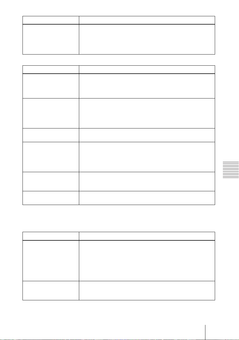
Symptom Cause and Remedy
The computer cannot be
controlled with the
presentation tool.
• The USB cable is used.
• The Ai r Shot is not used.
c The presentat ion tool is designed to us e w i t h the Air Shot.
Use the Remote Commander to operate the device connected via
the USB cable.
Others
Symptom Cause and Remedy
The LAMP/COVER
indicator flashes.
The LAMP/COVER
indicator lights up.
The TEMP/FAN indicator
flashes.
The TEMP/FAN indicator
lights up.
Both the LAMP/C OVER
and TEMP/F AN indicators
light up.
The control panel keys do
not function .
• The lamp cover or the air filter cover is detached.
c Attach the cover se curely (see pages 42 and 43).
• The lens protector does not open due to a problem.
c Slide the lens prot ector by hand, and then press t he I/
• The lamp has reached the end of its life.
c Replace the lam p (see page 41).
• The lamp becomes a high temperature.
c Wait for 60 seconds to cool down the lamp and turn on the
power again.
• The fan is broken.
c Consult with qual ified So ny per so nnel.
• The int er nal temperature is unusually high.
c Check to see if nothing is blocking the ventil at i on holes.
• The proj ector is used at a high alti t ude.
c Ensure that “High Altitude Mode” in the INSTALL SETTING
menu is set to “On.”
• The electrical system breaks down.
c Consult with qual ified So ny per so nnel.
• The control panel keys are locked.
c Unlock the control panel keys (see page 37).
1 key.
Maintenance
Warning Messages
Use the list below to check the meaning of the messages displayed on the screen.
Message Meaning and Re m edy
High temp.!
Probably use in high
altitude. Switch to high
altitude mod e on? Yes V
No v
High temp.!
Lamp off in 1 min.
• Internal temperature is too high.
c When using the projector at an altitude of 1,500 m or higher, set
“High Altitude Mode” in the INSTALL SETTING menu to
“On” (see page 40).
c If this message appears on the screen when using the projector
at normal altitudes, check to see if anythi ng is blocking the
ventilation holes (exh aust).
• Internal temperature is too high.
c Turn off the power.
c Check to see if nothing is blocking the ventil at i on holes.
Maintenance
47
GB
Page 48
Message Meaning and Remedy
Frequency is out of range! • This input signal cannot be projected as the frequency is out of the
Please check Input-A
Signal Sel.
Please replace the LAMP. • It is time to replace the lamp.
acceptabl e range of the projector.
c Input a signa l th at i s w i thin the range of the fr equency.
• The resolution setting of the output signal of a computer is too
high.
c Set the setting of output to XGA (see page 20).
• You have input RGB signal from the computer when “Input-A
Signal Sel.” in the SET SETTING menu is set t o “Component.”
c Set “Input-A Signal Sel.” correctly (see page 37).
c Replace the lamp .
Caution Messages
Use the list below to check the meaning of the messages displayed on the screen.
Message Meaning and Remedy
Not applicable! • You have pressed the wrong key.
The panel keys are locked ! • “Panel Key Lock” in the INSTALL SETTING menu is set to “On.”
c Press the appropriate key.
c All the keys on the cont rol panel of the proje ct or are locked.
Operate the projector with the keys on the Remote Commander
(see page 37).
GB
48 Maintenance
Page 49

B Others
Specifications
Optical characteristics
Projection system
LCD panel 0.79-inch XGA panel, about
Lens 1.2 times zoom le ns (po w ere d)
Lamp 190 W UHP
Projection pictur e siz e
Light output ANSI lumen
Throwing distance (Whe n pl ac ing on the floor)
There may be a slight difference between the
actual value and the design value shown above.
1) ANSI lumen is a measuring method of
American National Standard IT 7.228.
Electrical characteristics
Color system NTSC3.58/PAL/SECAM/
3 LCD panels, 1 lens, projecti on
system
2,360,000 pixels (786,432
pixels × 3)
f 23.5 to 28.2 mm/F1.6 to 1.78
40 to 300 inches (meas ured
diagonally)
(When the Lamp Mode is set to
“High”)
When the XGA signal is input
40-inch: 1.2 to 1.4 m
(3.9 to 4.6 feet)
60-inch: 1.8 to 2.0 m
(5.9 to 6.6 feet)
80-inch: 2.4 to 2.7 m
(7.9 to 8.9 feet)
100-inch: 3.0 to 3.4 m
(9.8 to 11.2 feet)
120-inch: 3.6 to 4.1 m
(11.8 to 13.5 feet)
150-inch: 4.5 to 5.2 m
(14.8 to 17.1 feet)
180-inch: 5.4 to 6.2 m
(17.7 to 20.3 feet)
200-inch: 6.0 to 6.9 m
(19.7 to 22.6 feet)
250-inch: 7.5 to 8.7 m
(24.6 to 28.5 feet)
300-inch: 9.0 to 10.4 m
(29.5 to 34.1 feet)
NTSC
PAL60 system, switched
automatically/manually
(NTSC
when playing back a vide o
1)
3000 lm
4.43/PAL-M/PAL-N/
4.43 is the color system used
recorded on NTSC on a
4.43 system VCR.)
Resolution 750 horizontal TV lines (Video
Acceptable compute r sign als
1) Set the resolution and the frequency of the
signal of the connected computer w ithin the
range of acceptable preset sign als of the
projector.
Applicable video signals
Speaker Monaural speaker system, 40 × 20
NTSC
input)
1,024 × 768 dots (RGB input)
fH: 19 to 92 kHz
fV: 48 to 92 Hz
(Maximum input signal resolution:
SXGA+ 1400 × 1050
fV: 60 Hz
15 k RGB 50/60 Hz, Progressive
component 50/60 Hz, DTV
(480/60I, 575/50I, 480/60 P ,
575/50P, 540/60P, 720/60P,
720/50P, 1080/60I, 1080/5 0I),
Composite video, Y/C video
mm (1
1 W
1)
5
/8 × 13/16 inches), max.
Input/Output
Video input VIDEO: pho no type
INPUT A HD D-sub15-pin (female)
Composite video: 1 Vp-p ±2 dB
sync negative (75 ohms
terminated)
S VIDEO: Y/C mini DIN 4-pin
type
Y (luminance): 1 Vp-p ±2 dB
sync negative (75 ohms
terminated)
C (chrominance): burst
0.286 Vp-p ±2 dB (NTSC)
(75 ohms terminated),
burst 0.3 Vp-p ±2 dB (PAL)
(75 ohms terminated)
AUDIO: stereo minijack
500 mVrms, impedance more
than 47 kilohms
Analog RGB/co mp onent:
R/R-Y: 0.7 Vp-p ±2 dB
(75 ohms terminated)
G: 0.7 Vp-p ±2 dB
(75 ohms terminated)
G with sync/Y: 1 Vp-p ±2 dB
sync negative
(75 ohms terminated)
B/B-Y: 0.7 Vp-p ±2 dB
(75 ohms terminated)
SYNC/HD:
Others
Specifications
49
GB
Page 50

Composite sync input: 1-5 Vp-p
high impedance, positive/
negative
Horizont al sync in put: 1-5 Vp -p
high impedance, positive/
negative
VD:
Vertical sync input: 1-5 Vp-p
high impedance, positive/
negative
AUDIO: Stereo minijack
(Common INPUT A/B)
500 mVrms, impedance more
than 47 kilohms
INPUT B Analog RGB: HD D-sub 15-pin
(female)
R: 0.7 Vp-p ±2 dB (75 ohms
terminated)
G: 0.7 Vp-p ±2 dB (75 ohms
terminated)
G with sync: 1 Vp-p ±2 dB sync
negative (75 ohms terminated)
B: 0.7 Vp-p ±2 dB (75 ohms
terminated)
SYNC HD: Composite sync
input: 1 - 5 Vp-p high
impedance, positive/nega ti ve
Horizontal sync input: 1 - 5 Vpp high impedance, positive/
negative
VD: Vertical sync input: 1 - 5
Vp-p high impedance, positive/
negative
USB Up (female) × 1
Wireless LAN card slot
× 1
Memory Stick slot
× 1
OUTPUT MONITOR OUT: HD D-sub 15-
pin (female)
R, G, B: Gain Unity: 75 ohms
SYNC/HD, VD: 4 Vp-p (open),
1 Vp-p (75 ohms)
AUDIO OUT (variable out):
Stereo minijack
max. 1 Vrms, when an input
signal is 500 mVrms,
impedance less than 5 kilohms
REMOTE RS-232C: D-sub 9 pin
Safety regulations
UL60950, cUL (CSA No. 60950),
FCC Class B, IC Class B,
DEMKO (EN60950), CE
(LVD, EMC), C-Tick
Output 1 mW
General
Dimensions 328 × 92.6 × 283.8 mm (13 ×
Mass Approx. 3.8 kg (8 lb 6 oz)
Power requirements
Power consumption
Heat dissipation
Operating temperature
Operatin g humidity
Storage temperature
Storage humidity
Supplied accessories
Design and spec ifications are subject to change
without notice.
3
/4 × 11 1/4 inches) (w/h/d)
3
(without the projection parts)
AC 100 to 240 V, 2.8 to 1.2 A, 50/
60 Hz
Max. 280 W
(in standby (standard): 7 W
in standby (low): 0.5 W)
921.3 BTU
0°C to 35°C (32°F to 95°F)
35% to 85% (no condensatio n)
–20°C to +60°C (–4°F to +140°F)
10% to 90%
Remote Commander (1)
Size AA (R6) batteries (2)
Presentation tool (1)
Size AAA (R03) batteries (2)
HD D-sub 15 pin cable (2 m) (1)
(1-791-992-21)
USB cable A type - B type (1)
(1-790-081-31)
CD-ROM (Application software
and Operating instruct ion) (1)
Wireless LAN card (1)
USB wireless LAN module (1)
USB storage media (1)
Carrying case (1)
AC power cord (1)
Air filter (for replacement) (1)
Operating Instructions (1)
Quick Refer e n ce Card (1)
Security Label (1)
Laser
Laser type Class 2
Wavelength 640 nm - 660 nm
GB
50 Specifications
Page 51

Optional accessories
Projector Lamp
LMP-C190
Signal Cable SMF-402 (HD D-sub 15-pin
Some of the items may not be available in some
areas. For details, pleas e consult your nearest
Sony office.
(for replacement)
(male) y 3 × phono type
(male))
Pin assignment
INPUT A/B connector (HD D-sub 15pin, female)
1R/R-Y 9N.C.
2 G/Y 10 GND
3 B/B-Y 11 GND
4 GND 12 DDC/SDA
5 GND 13 HD/C.Sync
6 GND (R) 14 VD
7 GND (G) 15 DDC/SCL
8 GND (B)
RS-232C connector (D-sub 9 pin,
female)
1DCD 6DSR
2RXDA 7RTS
3TXDA 8CTS
4DTR 9RI
5 GND
Others
Specifications
51
GB
Page 52

Input signals and adjustable/setting items
Adjust Picture... menu
Item Input signal
Contrast
Brightness
Color
Hue
Sharpness
Gamma
Mode
Color
Temp.
Vol u me
Video or S
video (Y/C)
zzzzzz
zzzzzz
zzz
z (NTSC 3.58/
4.43 only)
zzz
––
zzzzzz
zzzzzz
Component Video GBR Computer B&W Air Shot or
–––––
*
z
z : Adjustable/can be set
– : Not adjustable/cannot be set
*: Preset memory no. 3, 4 only
INPUT SETTING menu
Item Input signal
Dot
Phase
H Size –
Shift
Scan
Converter
Wide
Mode
Video or S
video (Y/C)
–––
–
–––
zz*2z
Component Video GBR Computer B&W Air Shot or
*1
z
*1
z
–
– z ––
z : Adjustable/can be set
– : Not adjustable/cannot be set
*1: Expect preset memory no.3, 4
*2: Expect preset m em ory no.5, 45, 47, 48, 50
Memory Stick
–––
–
z
z
z
z
( lower than
SVGA)
–
z
– z
––
––
––
z –
–
Memory Stick
GB
52 Specifications
Page 53

Preset signals
Memory
No.
1 Video 60 Hz 60 Hz 15.734 59.940
2 Video 50 Hz 50 Hz 15.625 50.000
3 480/60i 480/60i 15.734 59.940 S on G/Y or
4 575/50i 575/50i 15.625 50.000 S on G/Y or
5 1080/60i 1035/60i, 1080/6 0i 33.750 60.000
6 640 × 35 0 VGA mod e 1 31. 469 70.086 H-pos, V-neg 800
7 VGA VESA 85 Hz 37.861 85.080 H-pos, V-neg 832
8 640 × 400 PC-9801 Normal 24.823 56.416 H-neg, V-neg 848
9 VGA mode 2 31.469 70.086 H-neg, V-pos 800
10 VGA VESA 85 Hz 37.861 85.080 H-neg, V-pos 832
11 640 × 480 VGA mode 3 31.469 59.940 H-neg, V-neg 800
12 Macintosh 13" 35.000 66.667 H-neg, V-neg 864
13 VGA VESA 72 Hz 37.861 72.809 H-neg, V-neg 832
14 VGA VESA 75 Hz 37.500 75.000 H-neg V-neg 840
15 VGA VESA 85 Hz 43.269 85.008 H-neg V-neg 832
16 800 × 600 SVGA VESA 56 Hz 35. 156 56.250 H-pos, V-pos 1024
17 SVGA VESA 60 Hz 37.879 60.317 H-pos, V -pos 1056
18 SVGA VESA 72 Hz 48.077 72.188 H-pos, V -pos 1040
19 SVGA VESA 75 Hz 46.875 75.000 H-pos, V -pos 1056
20 SVGA VESA 85 Hz 53.674 85.061 H-pos, V -pos 1048
21 832 × 624 Macintosh 16" 49. 724 74.550 H-neg, V-neg 1152
22* 1024 × 768 XGA VESA 43 Hz 35.524 86.958 H-pos, V-pos 1264
23 XGA VESA 60 Hz 48.363 60.004 H-neg V-neg 1344
24 XGA VESA 70 Hz 56.476 69.955 H-neg V-neg 1328
25 XGA VESA 75 Hz 60.023 75.029 H-pos, V-pos 1312
26 XGA VESA 85 Hz 68.677 84.997 H-pos, V-pos 1376
27 1152 × 864 SXGA VESA 70 Hz 63.995 70.019 H-pos , V-pos 1472
28 SXGA VESA 75 Hz 67.500 75.000 H-pos, V-pos 1600
29 SXGA VESA 85 Hz 77.487 85.057 H-pos, V-pos 1568
30 1152 × 900 Sunmicro LO 61.795 65.960 H-neg, V-neg 1504
31 Sunmicro HI 71.713 76.047 Composite Sync 1472
Preset signal fH (kHz) fV (Hz) Sync SIZE
Composite Sync
Composite Sync
Others
Specifications
53
GB
Page 54

Memory
Preset signal fH (kHz) fV (Hz) Sync SIZE
No.
32 1280 × 960 SXGA VESA 60 Hz 60.000 60.000 H-pos, V-pos 1800
33 SXGA VESA 75 Hz 75.000 75.000 H-pos, V-pos 1728
34* 1280 × 1024 SXGA VESA 43 Hz 46.433 86.872 H-pos, V-pos 1696
35 SGI-5 53.316 50.062 S on G 1680
36 SXGA VESA 60 Hz 63.974 60.013 H-pos, V-pos 1696
37 SXGA VESA 75 Hz 79.976 75.025 H-pos, V-pos 1688
38 SXGA VESA 85 Hz 91.146 85.024 H-pos, V-pos 1476
43 480/60p 480/60p
31.470 60.000 S on G
(Progressive
component
44 575/50p 575/50p
31.250 50.000 S on G
(Progressive
component
45 1080/50i 1080/50i 28.130 50.000
47 720/60p 720/60p 45.000 60.000
48 720/50p 720/50p 37.500 50.000
50 540/60p 540/60p 33.750 60.000
52 1400 × 1050 SXGA+ 60 Hz 63.981 60.020 H-pos, V-pos 1688
Notes
• When a signal other than the preset signals shown above is input, the picture may not
appear properl y.
• Memory No. 22 and 34 show the interlace signal.
• When a SXGA+ signal is input, th e image may extend beyond the screen. In this case,
input a signal with no black edges around the image, and disconnect and reconnect the
cable or select the input signal by pressing INPUT key.
GB
54 Specifications
Page 55

Warning on power connection
Use the supplied power cord when you use the projector in your country.
Otherwise, use a proper power cord meeting the following specification.
The United States,
Canada
Plug type VM0233 290B YP-12A COX-07 –
Continental Europe UK, Ireland,
Australia, New
Zealand
1)
Japan
YP332
Female end VM0089 386A YC-13B COX-02 VM0310B YC-13
Cord type SJT SJT H05VV-F H05VV-F N13237/CO-228 VCTF
Rated Voltage &
Current
10A/
125V
10A/
125V
10A/
250V
10A/
250V
10A/250V 7A/125V
Safety approval UL/CSA UL/CSA VDE VDE VDE DENAN
1
Cord length
4.5 m (177
/4 inches) –
(max.)
1)
Use the correct plug for your country.
Specifications
55
Others
GB
Page 56

Installation Diagr am
Floor Installation (Front Projection)
Distance between the fron t of the cabinet
and the center of the lens
Wall
x
Center of the
screen
Front of the
cabinet
Center of the lens
Front of the lens
11
/16 )
(
17.4
c
Floor
b
a
Unit : mm (inches)
This section describes the examples of installing the projector on a desk, etc.
See the chart on page 57 concerning the installation measurements.
The alphabetical letters in the illustration indicate the distances below.
a: distance betwee n the screen and the center of the lens
b: distance between the floor and the center of the lens
c: distance between the floor and the bottom of the adjusters of the projector
x: distan ce between the floor and the center of the screen (free)
GB
56 Installation Diagram
Page 57

Unit: mm (inches)
SS 40 60 80 100 120 150 180 200 250 300
N
a
b
c
M
1160
(45
1350
(53
x-237
(x-93/8)
x-299
(x-117/8)
1760
3
/4)
(693/8)
2040
1
/4)
(803/8)
x-356
(x-14)
x-417
(x-161/2)
2360
(93)
2740
(108)
x-474
(x-183/4)
x-536
(x-211/8)
2970
(117)
3440
(1351/2)
x-593
(x-233/8)
x-654
(x-257/8)
3570
(1405/8)
4140
(1631/8)
x-711
(x-28)
x-773
(x-301/2)
4470
(1761/8)
5180
(204)
x-889
(x-35)
x-951
(x-371/2)
5380
(2117/8)
6230
(2453/8)
x-1067
(x-42)
x-1129
(x-441/2)
5980
(2351/2)
6930
(2727/8)
x-1185
(x-463/4)
x-1247
(x-491/8)
7490
(295)
8670
(3411/2)
x-1482
(x-583/8)
x-1543
(x-607/8)
9000
(3543/8)
10420
(4103/8)
x-1778
(x-701/8)
x-1840
(x-721/2)
a (N)={(SS × 23.177/0.7874)–50.4} × 1.025
a (M)={(SS × 28. 177/0.7874)–50.4} × 0.975
b=x–(SS/0.7874 × 4.667)
c=x–(SS/0.7874 × 4. 66 7+ 61.8)
The installation measurements and their calculation method for each lens are shown
above.
The alphabetical letters in the charts and calculation methods indicate the following.
SS:screen size measured diagonally (inches)
a: distance between the screen and the center of the lens
b: distance betw een the floo r and the center of the lens
c: distance between the floor and the adjusters of the projector
x: free
N: minimum
M: maximum
Installation Diagram
57
Others
GB
Page 58

Ceiling Installation (Front Projection)
D
D
D
Center of the Projector
Center of the screen
Center of the lens
a'
)
4
/
1
81.8 (3
)
4
/
1
82.2
(3
Holes for mounting a
projector suspension supp ort
104.5
1
(4
/8)
5
)
32
/
3.7 (
)
/
7
46.1 (1
)
4
/
1
56.7 (2
8
)
32
/
27
21.4 (
Ceiling
Center of the lens
x
Front of the
cabinet
L
A
M
P
/C
O
V
E
R
T
E
M
P
/
F
A
N
P
O
W
E
R
S
T
A
N
D
B
Y
SI
D
E
SHO
T
INPUT B
Z
O
O
M
FOCUS
Center of the lens
REMOTE RS-232C
AUDIOMONITOR
OUTPUT
VIDEOS VIDEO AUDIO
VIDEO IN
INPUT A
AUDIO
Center of the screen
b
Hole for mounting a
projector suspension
support (front)
17.4 (11/16)
3
119.2 (4
/4)
L
A
M
P/
C
O
V
E
R
T
E
M
P
/
F
A
N
PO
W
ER
ST
AN
D
B
Y
S
I
D
E
S
H
OT
Z
O
O
M
FOCUS
REMOTE RS-232C
IO
IO
IO
INPUT B
55.9
)
4
/
1
(2
Center of the lens
Distance between the fro nt of the
cabinet and the hole for mounting a
projector suspension supp ort (front)
Unit: mm (inches)
This section describes the examples for installing the projector on the ceiling.
When installing the projector on the ceiling, use a Projector Suspension Support
recommended by Sony.
For ceiling installation, ask for qualified Sony personnel.
See the chart on page 59 concerning the installation measurements.
The alphabetical letters in the illustrations indicate the distances below.
a’:distance between the hole (front) for mounting a projector suspe nsion suppo r t on
bottom surface of this projector and the center of the screen
b: distance between the hole (front) for mounting a projector suspension support on
bottom surface of this projector and the ceiling
x: distance between the ceiling and the center of the screen
GB
58 Installation Diagram
Page 59

Unit: mm (inches)
SS 40 60 80 100 120 150 180 200 250 300
N
a’
1260
1860
2470
3070
3670
4580
(495/8)
(731/4)
M
1450
2140
(571/8)
(843/8)
xb+293
bFree
(b+115/8)
b+411
(b+161/4)
(973/8)
2840
(1117/8)
b+530
(b+207/8)
(121)
3540
(1391/2)
b+649
(b+255/8)
(1445/8)
4240
(167)
b+767
(b+301/4)
(1803/8)
5280
(208)
b+945
(b+371/4)
5480
(2157/8)
6330
(2491/4)
b+1123
(b+441/4)
6090
(2397/8)
7030
(27613/16)
b+1241
(b+487/8)
7600
(2991/4)
8770
(3453/8)
b+1538
(b+605/8)
9100
(3583/8)
10520
(4141/4)
b+1834
(b+721/4)
a’ (N)={(SS × 23.177/0.7874)+51.4} × 1.025
a’ (M)={(SS × 28.177/0.7874)+51.4} × 0.975
x=b+(SS/0.7874 × 4.667+55.8)
The installation measurements and their calculation method for each lens are shown
above.
The alphabetical letters in the charts and calculation methods indicate the following.
SS:screen size measured diagonally (inches)
a’: distance between the hole (front) for mo unting a projecto r suspension support on
bottom surface of this projector and the center of the screen
b: distance betw een the hole (front) for mounting a projector suspension support on
bottom surface of this projector and the ceiling
x: distance between the center of the screen and the ceiling
N: minimum
M: maximum
Installation Diagram
59
Others
GB
Page 60

“Side Shot” and “V Keystone”
Adjustments
With “Side Shot” (horizontal keystone adjustment) provided for the projector, you can
project the picture from the side of the screen.
When projecting with “Side Shot” adjustment only, you can adjust the horizontal
distortion of the screen using “Side Shot” to the maximum.
When projecting with both “Side Shot” and “V Keystone” (vertical keystone adjustment),
you can adjust the vertical ( ) and horizontal ( ) distortion of the screen.
FOCUS
OM
ZO
SHOT
E
SID
POWER STANDBY
E
T
LAMP/COVER
N
MP/FA
SIDE SHOT key
Adjustment Areas of “Side Shot” and “V Keystone”
The adjustable distortion area using “Side Shot” and “V Keystone” is described below.
Screen
H
S
O
T
E
D
I
S
–
+
a
a
b
b
a: Tilting angle of the projec tor in the “V Keyston e” adjustment area
b: “Side Shot” (H Keystone adjustment) area
GB
60 “Side Shot” and “V Keystone” Adjustments
Page 61

Input signals a b
Video/60, Video/50, 480/60i, 575/50i,
480/60p, 575/50p
1080/60i, 1080/50i , 540/60p a=0 0 +/–16
720/60p, 720/50p a=0 0 +/–16
PC, Air Shot, Memory Stick a=0 0 +/–14
Notes
• If “V Keystone” is set to “Auto,” the “Side Shot” adjustment area may be narrow.
• “V Keystone” of the INSTALL SETTING menu is set to “Auto” at the factory, and the vertical
distortion of the picture is automatically corrected. However, the distortion may not be perfectly
corrected depending on the room temperature or the screen angle. In this case, set to “Manual,”
and correct the dist or t ion using values.
a=0 0 +/–20
0 or b≠0 +/–20 +/–11
a
≠
b=0 +/–30 0
0 or b≠0 +/–20 +/–11
a
≠
b=0 +/–30 0
0 or b≠0+/–20 +/–7
a
≠
b=0 +/–30 0
0 or b≠0+/–20 +/–7
a
≠
b=0 +/–30 0
“Side Shot” and “V Keystone” Adjustments
61
Others
GB
Page 62

Dimensions
76.1(3)
47.1
(1
Front
Center of the lens
Center of the projector
1
/4)
81.8(3
140.5(55/8)
Right side
/4)
3
18.6(
/8)
7
71.9(2
27
/8)
3
57.4(2
15
)6(
4
/
3
92.6(3
)
4
/
1
/32)
/16) 21(
23.7(
)
2
/
1
61.9(2
/8)
/8)
7
7
(1
47.1(1
47.1
/16)
13
20.1(
39.5(1
36.2(1
76.1(3)
76.1(3)
/32)
19
15(
82.2(3
9
/16)
7
/16)
(11/8)
Remote control
detector
34.4(1
3
/
8
1
/4)
245.8(9
3
/4)
)
328(13)
Hole for security lock
3
/4)
220.8(8
5
/8)
217.3(8
17.4(
11
/16)
Center of the lens
/2)
1
61.9(2
146.4(5 7/8)93.9(3 3/4)
1
256.3(10
/8)
3
245.1(9
/4)28
Unit: mm (inches)
GB
62 Dimensions
Page 63

Left side
Bottom
/4)
1
283.8(11
/2)
7
1
240.3(9
/16)
3
/4) 4.5(
1
81.2(3
/8)
/8)
1
223.7(8
205.1(8
35.3
(1 7/16)
/4)
3
144.3(5
/4)
3
195.2(7
/16)
13
45(1
/4)
3
119.2(4
23.5
15
(
/16)
5
/32)
7
(
244(9 5/8)
Center of the lens
82.2(3 1/4) 81.8(3 1/4)
46.8(1 7/8)
/4)
1
/8)
7
56.9(2
71.4(2
/8)
1
104.5(4
Center of the projector
217.6(8
31
/32) 6.8(9/32)
24.2(
1
56.7(2
/4) 46.1(1 7/8)
7
/32)
5.2(
21.4(
Projector suspension
support mounting surface
20.3
13
)
16
/
(
5
/8)
/16)79.4(3
3
29.4(1
/8)97.4(3
1
41.5
3
11
/4)
127.7(5
144.5(5
/8)
7
/16)
(1
/4)
1
/4)
3
94(3
Others
3
120.4(4
/4)
27
/32)
33.8(1 3/8)
Holes for mounting a projector
3-M4
suspension support
263(10 3/8) 33(1 5/16)
Center of gravity of the pr ojector
Unit: mm (inches)
Dimensions
63
GB
Page 64

Index
A
Adjusting
memory of the settings 32
the picture ...................33
the picture size/shift ...35
Air filter .........................43
Auto Input Search ..........37
B
Background ....................39
Brightness ......................33
C
Color ..............................33
Color System ..................37
Color Temp. ...................34
Connections
computer .....................20
VCR ............................22
Contrast ..........................33
D
Digital Zoom function ....29
Direct Power On/Off
function ...................29
Dot Phase .......................35
F
fH (Horizontal Frequency)
.................................40
fV (Vertical Frequency) .40
G
Gamma Mode .................34
H
H Size .............................35
High Altitude Mode .......40
Hue .................................33
I
Illumination ....................37
Image Flip ......................39
INPUT A/B connector
pin assignment ............51
Input-A Signal Sel. ........37
Input-C Select ................37
Installation examples .....19
notes .............................7
unsuitable conditions ....8
unsuitable installation .. 7
L
Lamp Mode ....................40
Lamp replacement ..........41
Lamp Timer ...................40
Language ........................38
selecting the menu
language ..............26
Lens Control .................. 40
Lens protector ................12
Location and function of
controls
connector panel ..........14
control panel ...............13
rear/right side/bottom .12
Remote Commander ..15
top/front/left side ........12
M
Menu
clearing t he menu display
.............................32
INFORMATION Menu
.............................40
INPUT SETTING menu
.............................34
INSTALL SETTING
menu ................... 39
MENU SETTING menu
.............................38
PICTURE SETTING
menu ................... 33
SET SETTING menu .36
using the menu ...........31
Menu Color ....................38
Menu Position ................38
Message
caution ........................ 48
warning .......................47
O
Off & unplug function ...29
Optional accessories ...... 51
P
Panel Key Lock ..............37
Picture Mode ..................33
Pin assignment ...............51
Power
turn on ........................23
Power consumption in
standby mode .........37
Power Saving .................37
Powered tilt adjuster ......24
Precautions .......................6
Presentation tool ............17
R
Remote Commander ......15
front remote control
detector ............... 12
location and function of
controls ............... 15
rear remote control
detector ............... 12
Reset
resettable items ...........32
resetting the item ........32
S
Scan Converter ............ ...35
Screen size ...............19, 49
Security Lock .................40
SET SETTING menu .....36
Sharpness ....................... 34
Shift ................................35
Side Shot ........................39
Smart APA .....................36
Specifications .................49
Startup screen .................23
Status ..............................38
Supplied accessories ...... 50
T
Test Pattern ....................39
Tilt... ...............................39
Troubleshooting ............. 44
U
USB connector ...............20
V
V Keystone ....................39
Volume ..........................33
GB
64 Index
Page 65

W
Wide Mode .....................34
Index
65
Others
GB
 Loading...