

Page 1
Data Projector VPL-CX80
2-178-203-11 (1)
Data Projector
Operating Instructi ons
Mode d’emploi
Manual de instrucci ones
VPL-CX80
GB
FR
ES
© 2004 Sony Corporation
Page 2
WARNING
Address: 1645 0 W. Bernardo Dr, San Dieg o,
CA 92127 U.S.A.
Telephone Number: 858-942-2230
To prevent fire or shock hazard, do
not expose the unit to rain or
moisture.
To avoid electrical shock, do not
open the cabinet. Refer servicing to
qualified personnel only.
This symbol is intended to
alert the user to the presence
of uninsulated “dangerous
voltage” within the
product’s enclo sure that may
be of sufficient magnitude to
constitute a risk of electric
shock to persons .
This symbol is intended to
alert the user to the presence
of important operating and
maintenance (servicing)
instructions in the literature
accompanying the
appliance.
For the customers in the USA
If you have any questions about this product,
you may call:
Sony Customer Information Service Center
1-800-222-7669 or http://www.sony.co m/
The number below is for FCC related
matters only.
Declaration of Conformity
Trade Name: SONY
Model No.: VPL-CX80
Responsible Party: Sony Electronics Inc .
This device complies with Part 15 of the
FCC Rules. Operation is subject to the
following two conditions: (1) This device
may not cause harmful interference, and (2)
this device must accept an y interference
received, including interference that may
cause undesi re d operation.
This equipment has been tested and found to
comply with the limits for a Class B digital
device, pursuant to Part 15 of the FCC
Rules. These limits are designed to provide
reasonable protection against harmful
interference in a residential installation.
This equipment generat es, uses, and can
radiate radio frequency energy and, if not
installed and use d in accordance with the
instructions, may cause harmful interfe rence
to radio communications. However, there is
no guarantee that interference will not occ ur
in a particular installation. If this equ ipmen t
does cause harmful interference to radio or
television reception, which can be
determined by turning th e equipment off and
on, the user is encouraged to try to correct
the interference by one or more of the
following measure s :
- Reorient or relocate the receiving antenna.
- Increase the separation between the
equipment an d receiver.
- Connect the equipment into an outlet on a
circuit different from that to which the
receiver is connected.
- Consult the dealer or an experienced radio/
TV technician for help.
You are cautioned that any changes or
modifications not expressly approved in this
manual could vo id your authori ty to ope rate
this equipment.
This product contains mercury.Disposal of
this product may be regulated if sold in the
United Stat es . For disposal or r ec ycling
information, please contact yo ur loc a l
authorities or Electronics Industries Allianc e
(www.eiae.org http://www.eiae.org).
GB
2
Page 3
For the customers in Canada
This Class B digital apparatus complies with
Canadian ICES-003.
Voor de klanten in Nederland
Gooi de batterij niet weg
maar lever deze in als klein
chemisch afval (KCA).
The socket-outlet should be installed ne ar
the equipment and be easily accessible.
CAUTION
RISK OF EXPLOSION IF BATTERY IS
REPLACED BY AN INCORRECT
TYPE.
DISPOSED OF USED BATTERIES
ACCORDING TO THE
INSTRUCTIONS.
GB
3
Page 4

Table of Contents
Overview
Precautions ......................................... 6
Notes on Installation ..........................7
Unsuitable Installation .................7
Unsuitable Conditions ..................8
Usage in High Altitude .................8
Features .............................................. 9
Location and Function of Controls .11
Top/Front/Left Side ....................11
Rear/Right Side/Bottom .............11
Control Panel ..............................12
Connector Panel .........................13
Remote Commander ...................14
Setting Up and Projecting
Installing the Projector .....................16
Connecting the Projector .................17
Connecting with a Computer ..... 17
Connecting with a VCR .............19
Projecting ......................................... 20
Turning Off the Power ...............22
Convenient Function
Selecting the Menu Language ..........23
Security Lock ...................................24
Other Functions ................................25
Switching from the Intelligent Auto-
setup Function to Manual
Adjustments ....................25
Controlling the Computer Using the
Supplied Remote
Commander (When Using
the USB Cable) ................25
Off & Go Function ......................25
Direct Power On/Off Function ...26
Effective Tools for Your
Presentation .....................26
Adjustments and Settings
Using the Menu
Using the MENU ..............................27
The PICTURE SETTING Menu ......29
The INPUT SETTING Menu ...........30
The SET SETTING Menu ................32
The MENU SETTING Menu ...........34
The INSTALL SETTING Menu ......35
The INFORMATION Menu ............36
Maintenance
Maintenance .....................................37
Replacing the Lamp ....................37
Cleaning the Air Filter ................38
Troubleshooting ................................40
Warning Messages ......................43
Caution Messages .......................44
Others
Specifications ...................................45
Installation Diagram .........................52
Floor Installation (Front
Projection) .......................52
GB
4
Page 5

Ceiling Installation (Front
Projection) .......................54
“Side Shot” and “V Keystone”
Adjustments .....................................56
Dimensions .......................................58
Index ...............................................60
GB
GB
5
Page 6

B Overview
Precautions
are of reflecting material, it is
recommended that the carpet and wall
paper be changed to a dark color.
On safety
• Check that the operating voltage of your
unit is identical with the voltage of your
local power supply.
• Should any liquid or solid object fall into
the cabinet, unpl ug the unit an d ha v e it
checked by qualified personnel before
operating it further.
• Unplu g the uni t from the wall outlet i f it is
not to be used for sev e ral days.
• To disconnect the cord, pul l i t out by the
plug. Never pull the cord itself.
• The wall outlet should be near the unit and
easily accessible.
• The unit is not disconnected to the AC
power source (mains) as long as it is
connected to the wall outlet , even if the
unit itself has been turned off.
• Do no t look i nto the lens while the la mp is
on.
• Do no t place your han d or objects nea r the
ventilation holes. The air coming out is
hot.
• Be ca reful no t to have your fin gers ca ught
by the adjuster. The powered tilt adjuster
of this unit automatically extends when the
power is turned on, and is put away
automatically when the power is turned
off. Do not touch the unit while the
adjuster is in operation. Adjust the
powered tilt adjuster carefully after its
automatic operation is completed.
• Do not spread a cloth or paper under the
unit.
On illumination
• To obtain the best picture, the front of the
screen should not be exposed to direct
lighting or sunlight.
• Ceiling-mounted spot lighting is
recommended. Use a cover over
fluorescent lamps to avoid lowering the
contrast ratio.
• Cover any windows that face the screen
with opaque draperies.
• It is desirable to install the unit in a room
where floor and walls are not of lightreflecting material. If the floor and walls
On preventing internal heat buildup
After you turn off the power with the I / 1
key, do not disconnect the unit from the wall
outlet while the cooling fan is still running.
Caution
The unit is equipped with ventilation holes
(intake) and ventilation holes (exhaust). Do
not block or place anything near these holes,
or internal heat build-up may occur, causing
picture degradation or damage to the
projector.
On cleaning
• To keep the cabinet looking new,
periodically clean it with a soft cloth.
Stubborn stains ma y be removed with a
cloth lightly dampened with a mild
detergent solution. Never use strong
solvents, such as thinner, benzene, or
abrasive cleansers, since these will
damage the cabinet.
• Avoid touc hin g the len s. T o remo ve dust
on the lens, use a sof t dry cloth. Do no t use
a damp cloth, dete rgent solution, or
thinner.
• Clean the filter at regular intervals.
On LCD data projector
• The LCD data projector is manufactured
using high-precision technology. You
may, however, see tiny black points and/or
bright points (red, blue, or green) that
continuously ap pear on the LCD data
projector. This is a normal result of the
manufacturing process and does not
indicate a malfunction.
GB
6 Precautions
Page 7
Notes on Installation
Unsuitable Installation
Do not install the projector in the following
situations. These installations may cause
malfunct ion or damage to the unit.
Poorly ventilated
• Allow adequate air circulation to prevent
internal heat build-up. Do not place the
unit on surfaces (rugs, blankets, etc.) or
near materials (curtains, draperies) that
may block the ventilatio n holes. When the
internal heat builds up due to the block-up,
the temperature sensor will function with
the message “High temp.! Lamp off in 1
min.” The power will be turned off
automatically after one minute.
• Leave space of more than 30 cm (11
inches) around the unit.
• Be careful that the ventilation holes may
inhale tininess such as a piece of paper.
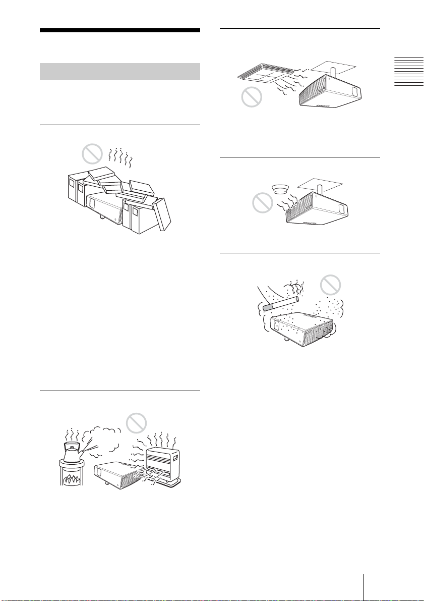
Highly heated and humid
7
/8
Subject to direct cool or warm air
from an air-conditioner
Installing in such a location may cause
malfunction of the unit due to moisture
condensation or rise in temperature.
Near a heat or smoke sensor
Malfunction of the sensor may be cause d.
Very dusty, extremely smoky
Avoid installing the unit in a very dusty or
extremely smoky environment . Otherwise,
the air filter will become obstructed, and this
may cause a malfunction of the unit or
damage it. Dust preventing the air passing
through the filter may cause a rise in the
internal temperature of the unit. Clean the
filter periodically.
Overview
• Avoid installing the unit in a location
where the temperature or humidity is very
high, or temperature is very low.
• To avoid moisture condensation, do not
install the unit in a location where the
temperature may rise rapidly.
Notes on Installation
GB
7
Page 8
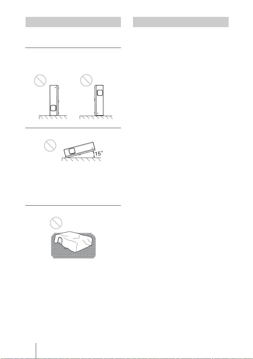
Unsuitable Conditions Usage in High Altitude
Do not use the pr ojector unde r the follo wing
conditions.
Toppling the unit
Avoid using as the unit topples over on its
side. It may cause mal function.
Tilting the unit to the right or left
Avoid tilting the unit to an angle o f 15°, and
avoid installi ng the unit in any way ot her
than placing on th e floor or susp ending fro m
the ceiling. Such installation may cause
color shading or shorten the lamp life
excessively.
When using the p rojector at an altitude of
1,500 m or higher, turn on “High
Altitude Mode” in the INSTALL SETTING
menu. Failing to set this mode when using
the projector at high altitudes could have
adverse effects, such as reducing
the reliability of certain components.
Note on carrying the projector
The unit is manuf actured using highprecision technology. When transporting the
unit stored in the carrying case, do not drop
the unit or subject it to shock, as this may
cause damage. When storing the unit in the
carrying c ase, disc onnect the AC power cord
and all other connecting cables, and store the
supplied accessories in a pocket of the
carrying case.
Note on the screen
When using a screen with an uneven surface,
stripes pattern may rarely appear on the
screen depending on the distance between
the screen and the projector or the zooming
magnifications. This is not a m alfun c tio n of
the projector.
Blocking the ventilation holes
Avoid using a thick-piled carpet or anything
that covers the ventilation hole s (exhaust/
intake); otherwise, the internal heat may
build up.
For details on the ventilation holes (intake/
exhaust), see “Location and Function of
Controls” on page 11.
GB
8 Notes on Installation
Page 9
Features
About this manual
The Illustrations indicated in th is manual
may differ from those of this model in
specifications.
High brightness, high picture
quality
High brightness
Adopting Sony's unique new optical system
that incorporates newly developed LCD
panels provides a high-efficiency optical
system. It allows the 190 W UHP lamp to
give a light output of 3000ANSI lumen.
High picture quality
Three super-high-aperture 0.79-inch XGA
panels with approximately 790,000-pixel
micro-lens array, produce a resolution of
1024 × 768 dots (horizontal/vertical) for
RGB input, and 750 horizontal TV lines for
video input.
Quiet presentation environment
Low fan noise is achieved and offensive
sound to the ear is also reduced, allowing
you to run an optim um p r es e nt ation even in
a quiet environment.
Easy setup and simple operation
Short focal lens equipped
The projection distance is very short,
approximately 2.4 m (7.8 feet), when
projecting an 80-inch image, which allows
projection on a larger screen even in a
limited space.
Side Shot
The projector supp orts the Side Sh ot featu re
(horizon tal t rape zoida l cor rect ion f unct ion),
enabling projection from the side of the
screen. Installation availability becomes
wider.
Off & Go feature
The cooling fan built in the projector will
work even after turning the power off and
the power cord is disconnected. This enables
you to move the projector to another location
immediately after turning it off.
Versatile installation capability
Capable of floor, ceiling or tilt
installation
In addition to the front floor or ceiling
installation, you can install the projector by
tilting it 90 degree s at the rear or 9 0 degre es
in front.
Direct Power On/Off function
The AC power of the entire system can be
directly turned on/off with a breaker or other
switch without pressing the power key on
the projector.
Overview
Intelligent Auto-setup function
Simply press the power key , an d the
projector automatically performs the setups
required before use. The projector opens the
lens protector, corrects the V Keystone,
detects a signal, and sets optimum
conditions for proje ction.
Powered zoom/focus equipped
The projector is equipped with a powered
zoom and powered focus lens, allowing you
to adjust the size and focus of an image with
the Remote Commander away from the
projector.
Features
GB
9
Page 10

Security Functions
Security lock
This function makes it possible to project no
picture on the screen unless the required
password is entered when the projector is
turned on.
Panel key lock
This function locks all the operatio n keys on
the control panel of the projector, allowing
use of the keys on the Remote Commander.
This prevents the projector from operating
incorrectly.
..............................................................................................................................................................
• Windows is a registered trademark of Microsoft Corporation in the United States and/or other
countries.
• VGA, SVGA, XGA and SXGA are registered trademar ks of the International Business
Machines Corporation, U.S.A.
• Kensington is a registered trademark of Kensington Technology Group.
• Macintosh is a registered trademark of Apple Computer, Inc.
• VESA is a registered trademark of Video Electronics Standard Association.
• Display Data Channel is a trademark of Video Elect ronics Standard Association.
• Side Shot is trademark of Sony Corporation.
GB
10 Features
Page 11
Location and
4
q
Function of Co ntrols
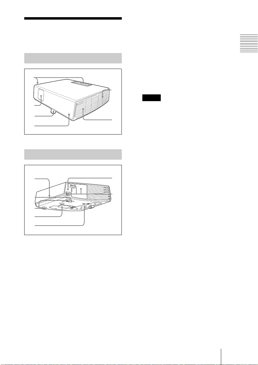
Top/Front/Left Side
1
5
2
3
Rear/Right Side/Bottom
6
8 Ventilation holes (intake)
9 Adjuster (hind pad)
Turn the adjuster to the right or left for
minor tilt adjustment of the projected
picture.
q; Ventilation holes (intake)/Lamp
cover
qa Ventilation holes (intake)/Air
filter cover
Notes
• Do not place anything near the
ventilation holes as this may cause
internal heat build-up.
• Do not place your hand or objects
near the ventilat io n holes as this may
cause a heat build-up.
• To maintain optimal p erformance, clean
the air filter every 1000 hours.
For details, see “Cleaning the Air
Filter” on page 38.
Overview
7
8
qs
qd
9
q;
a
1 Control panel
For details, see “Control Panel” on
page 12.
2 Lens protector (lens cover)
The lens protector automatically opens
when the power is turned on.
3 Powered tilt adjuster
4 Front remote control detector
5 Ventilation holes (exhaust)
6 Speaker
7 Rear remote control detector
qs Security lock
Connects to an optional security cable
(Kensington’s).
Web page address:
http://www.kensington.com/
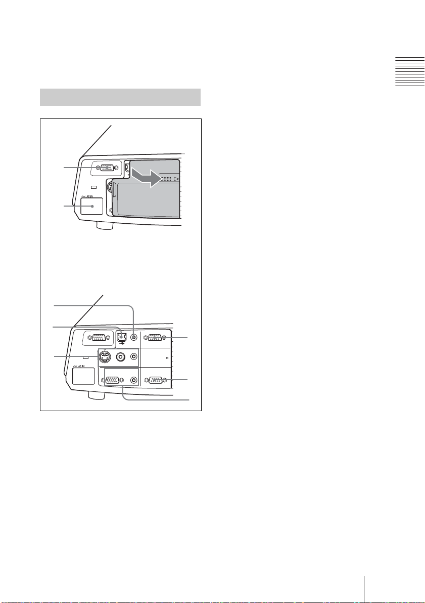
qd Connector/Connector Panel
For details, see “Connector Panel” on
page 13.
Location and Function of Controls
11
GB
Page 12
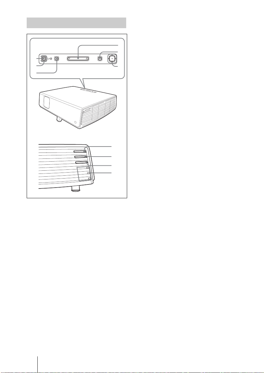
Control Panel
PUSH
MENUINPUT
1
TILT
2
3
FOCUS
M
O
O
Z
O
H
S
E
ID
S
N
A
ST
R
E
W
O
P
M
E
T
LAMP/COVER
1 I / 1 (on/standby) key
Turns on the projector when the
projector is in standby mode. The ON/
STANDBY indicator around the I / 1
key lights in green when the power is
turned on.
2 ON/STANDBY indicator (located
around the
I / 1 key)
Lights up or flashes un der the foll owing
conditions:
– Lights in red when an AC power cord
is plugged into a wall outlet. Once in
standby mode, you can turn on the
projector with the I / 1 key.
– Lights in green when the power is
turned on.
– Flashes in green while the cooling fan
is running after the power is turned off
with the I / 1 key. The fan runs for
about 60 seconds after the power is
turned off.
GB
12 Location and Function of Controls
ENTER
T
BY
D
N
A
F
/
P
7
8
9
0
4
5
6
For details on the I/1 indicators, see
page 22.
3 INPUT key
4 TILT adjustment key
For details, see “Projecting” on
page 20.
5 MENU key
Displays the on-screen menu. Press
again to clear t he me nu.
6 ENTER/Arrow(f/F/g/G) keys
Enter the settings of items in the menu
system.
Select the menu or make various
adjustments.
7 FOCUS +/– keys
Adjusts the picture focus.
8 ZOOM +/– keys
Adjusts the picture size.
9 SIDE SHOT +/– key
Adjusts the horizontal tr apezoidal
distortion/H keyst on e c orr ec tio n of the
picture.
For details, see “Sid e Sh ot” on pag e 35
and ““Side Shot” and “V Keystone”
Adjustments” on pa ge 56.
q; Indicators
• POWER SAVING
Lights when the projector is in power
saving mode.
• TEMP (Temperature)/FAN
Lights or flashes und er the following
conditions:
– Lights when the temperature inside
the projector becomes unusually
high.
– Flashes when the fan is broken.
For details on the TEMP/FAN
indicator, see page 43.
• LAMP/COVER
Lights or flashes und er the following
conditions:
– Lights when t he lamp has reached
the end of its life or reaches a high
temperature.
Page 13
– Flashes when the lamp cover or air
filter cover is not secured firmly.
For details on the LAMP/COVER a nd
TEMP/FAN indicator, see page 43.
Connector Panel
1
2
Open the cover when using the INPUT B or
VIDEO IN connector. To open the cover,
push the cover and slide it toward the right
until it locks.
To close the cover, press the cover to unlock
it and slide the cover toward the left.
INPUT A
VIDEO IN
VIDEOS VIDEO AUDIO
OUTPUT
3
4
AUDIO
INPUT A/B
INPUT A
5
S VIDEO
VIDEO IN
VIDEO
OUTPUT
AUDIO
AUDIOMONITOR
1 INPUT A connector (HD D-sub
15-pin, female)
Inputs a computer sig nal , video GBR
signal, component signal, or DTV signal
depending on equipment to be
connected.
Connects to the output connector of
equipment using the supplied cable or an
optional cable.
For details, see “Connecting with a
Computer” on page 17 and
“Connecting with a VCR” on page19.
AUDIO
AUDIOMONITOR
INPUT B
PUSH SLIDE
REMOTE RS-232C
INPUT B
COVER
LOCK/UNLOCK
REMOTE
RS-232C
6
7
8
2 AC IN socket
Connects the supplied AC power cord.
3 AUDIO (stereo minijack)
connector (common INPUT A/B)
When listening to sound ou tput from the
computer, conn ect to the audi o output of
the computer.
4 USB connector (USB plug for
upstream, 4-pin)
Connect to the USB connector of a
computer. When you connect the
projector to the computer, you can
control the mouse function with the
supplied Remote Comma nd e r.
5 VIDEO IN (Video input)
connector
Connect to external video equipment
such as a VCR.
• S VIDEO (mini DIN 4-pin):
Connects to the S video output (Y/C
video output) of video equipment.
• VIDEO (phono type): Connect s to
the composite video output of video
equipment.
• AUDIO (stereo minijack): Connects
to the audio output of the VCR.
6 INPUT B connector (HD D-sub
15-pin, female)
Connect to external equipment such as a
computer.
Connects to the monitor output of a
computer using an opti onal cable.
7 RS-232C connector (D-sub 9-
pin, female)
Connects to a computer to operate the
projector from the computer.
8 OUTPUT connector (HD D-sub
15-pin, female)
• MONITOR: Connect to the video
input connector of the monitor.
Outputs signals from the selected
channel and computer sign als only
from among the signals from t he
INPUT A or INPUT B.
• AUDIO (stereo minijack): Connects
to external active speakers. The
Overview
Location and Function of Controls
13
GB
Page 14
volume of the speakers can be
controlled by the VOLUME+/– keys
on the Remote Commander.
When INPUT A or B is selected, the
sound input to the AUDIO connector
which is common for INPUT A/B is
output.
When VIDEO or S VIDEO is selected,
the sound input to the AUDIO input
connector of VIDEO I N is output.
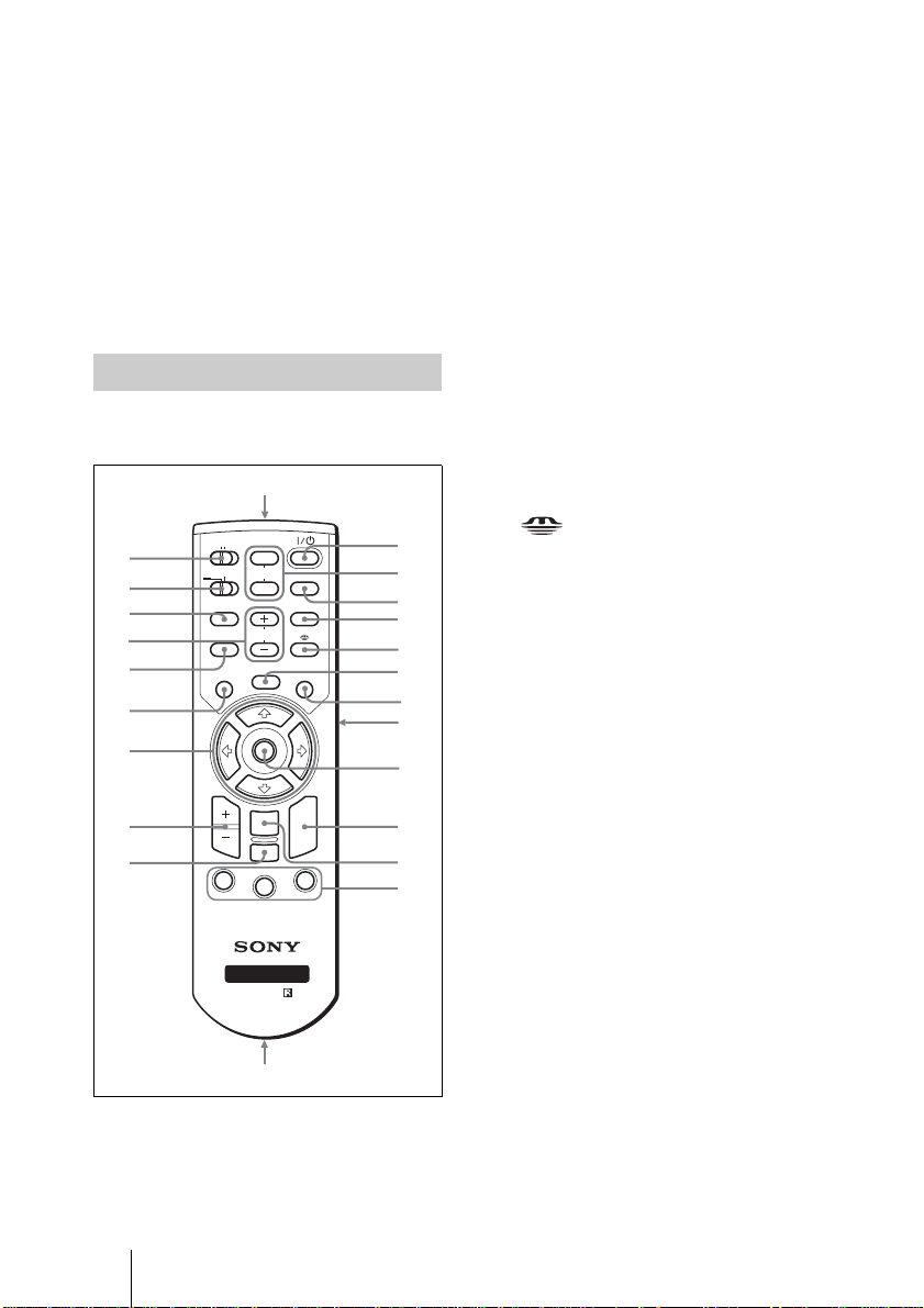
Remote Commander
The keys that have the same names as those
on the control panel function identically.
wa
COMMAND
ON
w;
ql
qk
qj
qh
qg
qf
qd
qs
OFF
PJ NETWORK
LENS
APA
MENU/
TAB
D ZOOM
1
PIC
MUTING
AUDIO
TILT/KEYSTONE
VOLUME
FREEZE
ENTER
RESET/
ESCAPE
2
FUNCTION
RM-PJM15
PROJECTOR
RM-PJM17
INPUT
AIR SHOT
R
CLICK
3
1
2
3
4
5
6
7
8
8
8
9
q;
a
b
c
• PIC: Cuts off the pictur e . Pr e s s again
to restore the picture.
• AUDIO: Press to te mporaril y cut off
the audio output from the speaker, and
the output on the AUDIO jack in the
OUTPUT section. Press again or press
VOLUME + key to restore the sound.
3 INPUT key
4 TILT/KEYSTONE (Vertical/
horizontal trapezoidal distortion
correction) key
Adjusts the tilt of the projector, or the
horizonal/vertical trapezo i dal distortion
of the image manually. Ea ch time you
press this key, the Tilt menu, the V
Keystone menus and Side Shot menu are
displayed. Use the arrow keys (M/m/
</,) for adjustment.
5 (Memory Stick) key
This key does not work in this un it.
6 FREEZE key
Freezes the picture projected. To cancel
the frozen picture, press t he key again.
7 AIR SHOT key
This key does not work in this un it.
8 Keys that emulate a mouse
These keys functi on as mouse buttons of
a computer only when the pr ojector is
connected to the computer using the
USB cable.
For details, see “Controlling the
Computer Using the Supplied Remote
Commander (When Using the USB
Cable)” on page 25.
9 ENTER key
q; FUNCTION 1, 2, 3 keys
These keys do not wo rk in this unit.
qa
1 I / 1 (on/standby) key
2 MUTING keys
Cut off the picture and sound.
GB
14 Location and Function of Controls
qa Strap holder
For attaching a strap.
qs RESET/ESCAPE key
Functions as a RESET key.
Resets the value of an item to its factory
preset value or returns the enlarged
Page 15
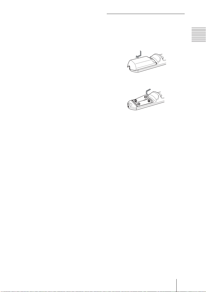
image to its original size. This key
functions when the menu or a setting
item is displayed on the screen.
qd D ZOOM (Digital Zoom) +/– key
Enlarges the image at a d e sired location
on the screen.
qf Arrow keys (M/m/</,)
qg MENU/TAB key
Functions as a MENU key.
To install batteries
1 Push and slide to open the lid, then
install the two size AA (R6) batteries
(supplied) with the correct polarity.
Overview
While pressing the lid, slide it.
qh APA (Auto Pixel Alignment) key
Automatically adjusts a picture to its
clearest while a signal is input from a
computer.
For details on APA, see “Smart APA” in
the SET SETTING menu on page 32.
qj VOLUME +/– keys
qk LENS key
Each time you press this key, Focus
adjustment menu and Zoo m adjustment
menu are displayed alter nately.
ql PJ/NETWORK (Projector/
Network) selector switch
Normally, set to “PJ”.
w; COMMAND ON/OFF switch
When this switch is set to OFF, no key
on the Remote Commander function.
This saves battery power.
wa Infrared transmitter
Be sure to install the battery
# side.
from the
2 Replace the lid.
Notes on Remote Commander
• Ma ke su re that nothing obstructs the
infrared beam between the Remote
Commander and the remote control
detector on the projector. Direct the
Remote Commander toward the front or
rear remote control detector.
• The operation range is limited. The shorter
the distance between the Remote
Commander and the projector is, the wider
the angle within which the commander can
control the projector becom es.
Location and Function of Controls
15
GB
Page 16
B Setting Up and Projecting
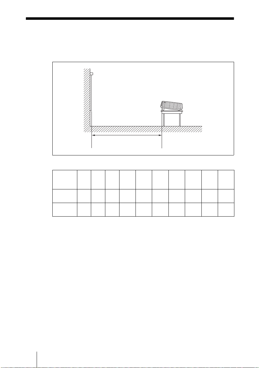
Installing the Projector
The distance between the lens and the screen varies depending on the size of
the screen. Use the following table as a guide.
Screen
Distance between the screen and
the center of the lens
Screen
size
(inches)
Minimum
Distance
Maximum
Distance
There may be a slight difference between the actual value and the design value shown
in the table above.
40 60 80 100 120 150 180 200 250 300
1.2
1.8
2.4
3.0
(3.9)
1.4
(4.6)
(5.9)
2.0
(6.6)
(7.9)
2.7
(8.9)
(11.2)
(9.8)
3.4
3.6
(11.8)
4.1
(13.5)
4.5
(14.8)
5.2
(17.1)
5.4
(17.7)
6.2
(20.3)
6.0
(19.7)
6.9
(22.6)
Unit: m (feet)
7.5
8.7
9.0
(29.5)
10.4
(34.1)
(24.6)
(28.5)
For details on installation, see “Installation Diagram” on page 52.
GB
16 Installing the Projector
Page 17
Connecting the
Projector
When you connect the projector,
make sure to:
• Turn off all equipment before making any
connections.
• Use the proper cables for each connection.
• Insert the cable plugs firmly; loose
connections may increase noise and
reduce performance of picture signals.
When pulling out a cable, be sure to pull it
out from the plug, not the cable itself.
To connect the projector, refer to
the illustrations on the next and the
following pages.
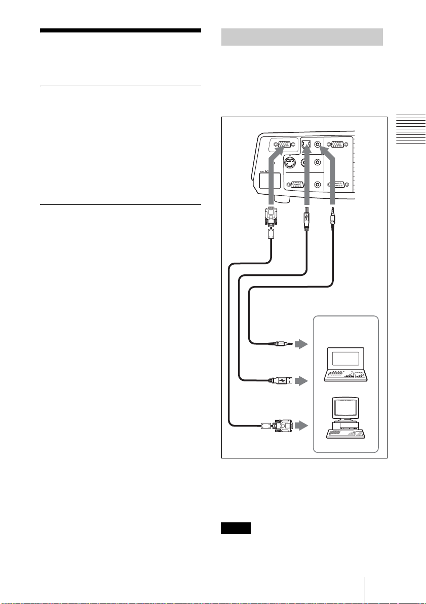
Connecting with a Compute r
This section describes how to connect the
projector to a computer.
For more information, refer to the
computer’s ins tr u c tio n ma nu a l .
To connect a computer
Right side
INPUT B
VIDEO IN
VIDEOS VIDEO AUDIO
OUTPUT
AUDIO
AUDIOMONITOR
REMOTE RS-232C
123
INPUT A
Setting Up and Projecting
to audio output
to USB connector
to monitor output
1 Stereo audio connecting cable (not supplied)
(Use a no-resistance cable.)
2 USB cable (supplied)
(Connect the USB cable to use a wireless
mouse.)
3 HD D-sub 15-pin cable (supplied)
Computer
Notes
• The projector accepts VGA, SVGA, XGA,
SXGA and SXGA+ signals. However, we
recommend that you set the output mode of
Connecting the Projector
17
GB
Page 18

your computer to XGA mode for the ext ernal
monitor.
• If you set your computer, such as a notebook
type, to output the signal to both your
computer’s display and the external monitor,
the picture of the external monitor m ay not
appear properly. Set your computer to output
the signal to only the external monitor.
For details, refer to the computer’s
operating instructions supplied with your
computer.
On the USB function
When connecti ng the projector to a
computer by using the USB cable for the
first time, the computer re cognizes the
hu
man interface device (wireless mo use
USB
function) automatically.
Recommended operating
environment
When you use the USB function, connect the
USB cable as illustrated above. The USB
function can be used on a computer loaded
with Windows 98, Windows 98 SE,
Windows ME, Windows 2000 or Windows
XP preinstall models.
To connect a Macintosh computer
To connect a Macintosh computer equipped
with video output connector of a type having
two rows of pins, use a commercially
available plug adaptor. When you connect a
USB capable Macintosh computer using the
USB cable to the projector, wireless mouse
functions becom e available.
Notes
• Your computer may not start correctly
when connected to the projector via the
USB cable. In this case, disconnect the
USB cable, restart the computer, then
connect the computer to the pro jector
using the USB cable.
• This projector is not guaranteed for
suspend, standby mode. When you use the
projector in susp end, standby mode ,
disconnect the projector from the USB
port on the computer.
• Operations are not guaranteed for all the
recommended computer env ironments.
GB
18 Connecting the Projector
Page 19
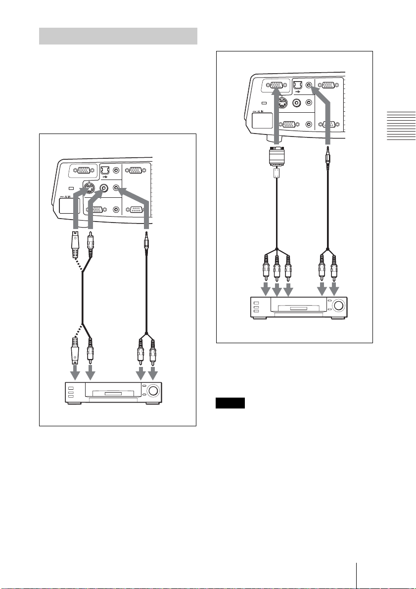
Connecting w ith a VCR
This section describes how to connect the
projector to a VCR.
For more information, refer to the
instruction manuals of the equipment you
are connecting.
To connect to a video or S video
output connector
Right side
INPUT B
VIDEO IN
VIDEOS VIDEO AUDIO
OUTPUT
AUDIO
AUDIOMONITOR
REMOTE RS-232C
INPUT A
To connect to a video GBR/
Component output
Right side
INPUT B
VIDEO IN
VIDEOS VIDEO AUDIO
OUTPUT
AUDIO
AUDIOMONITOR
REMOTE RS-232C
INPUT A
21
Setting Up and Projecting
21
to audio
to S
video
output
output (L)
to video
output
VCR
1 Stereo audio connectin g cable (n ot supplied)
(Use a no-resistance cable.)
2 Video cable (not supplied) or S-Video cable
(not supplied)
to audio
output
(R)
to
to video
GBR/
component
audio
output
(L)
output
VCR
1 Stereo audio connecting cable (not supplied)
(Use a no-resistance cable.)
2 SMF-402 Signal Cable
(not supplied)
HD D-sub 15-pin (male) ↔ 3 × phono jack
Notes
• Set the aspect ratio using “Wide Mode” in
the INPUT SETTING menu according to the
input signal.
• When you connect the projector to a video
GBR or component outp ut connector, select
“Video GBR” or “Co m ponent” with the
“Input-A Signal Sel.” setting in the SET
SETTING menu.
• Use the composite sync signal when you
input the externa l sync signal from vid eo
GBR/component equipment.
to
audio
output
(R)
Connecting the Projector
19
GB
Page 20

Projecting
2
4
ON/STANDBY indicators
Rear remote
control
detector
COMMAND
ON
OFF
PJ NETWORK
LENS
APA
MENU/
TAB
1 Plug the AC power cord into a wall
outlet, then connect all equipment.
The ON/STANDBY indicator lights in
red and the projector goes into standby
mode.
2 Press the I / 1 key.
The ON/STANDBY indicator lights in
green and the Intelligent Auto-setup
starts. The lens p rotec tor ope ns, and t he
powered tilt adjuster rises and stops at
the previously adjusted position .
PIC
MUTING
AUDIO
VOLUME
FREEZE
5
TILT
INPUT
TILT/KEYSTONE
AIR SHOT
PUSH
MENUINPUT
ENTER
2
4
5
6
1
3 Turn on the equipment connected to
the projector.
4 Press the INPUT key to select the
input source.
Each time you press the key, the input
signal switches as follows:
INPUT-A t INPUT-B t VIDEO t S-VIDEO
t
To input from Press INPUT to
display
Computer connecte d t o
INPUT-A
the INPUT A conne ct o r
Computer connecte d t o
INPUT-B
the INPUT B connector
Video equipment
VIDEO
connected to the VIDEO
input connector
Video equipment
S-VIDEO
connected to the S VIDEO
input connector
Smart APA (Auto Pi xel Alignment)
adjusts the picture of the connected
equipment so that it is projected clearly.
Notes
• If “Auto Input Search” is set to “On,” the
projector searches for the signals from
the connected equi pm ent and displays
the input channel where the input signals
are found.
For details, see “Aut o Input Search”
on page 33.
• The Smart APA is effective for the input
signal from a computer only.
5 Switch the equipment to be connected
to output to the projector.
Depending on the type of your
computer, for example a notebook, or an
all-in-one LCD type, yo u ma y hav e to
switch the computer to output to the
projector by pr essing certain keys
(e.g., , etc.), or by
changing your computer’s settings.
VGA
LCD
//
,
GB
20 Projecting
Page 21
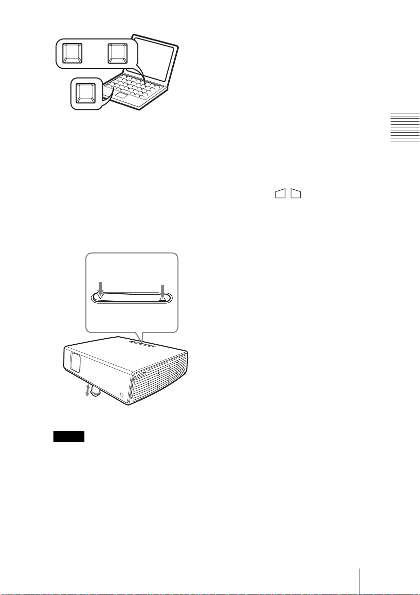
F7
or
Fx
and
Fn
6 Adjust the upper or lower position of
the picture.
To adjust using the Remote
Commander
Press the TILT/KEYSTONE key on the
Remote Commander to display the Tilt
menu and adjust the tilt using the M/m/
</, keys.
To adjust using the control panel
Press f or F of the TILT key to adjust
the tilt of the projector.
to lower the
projector
TILT adjustment key
to raise the
projector
TILT
on the room temp erature or the screen
angle. In this case, adjust it manually.
• Press the TILT/KEYSTONE key on the
Remote Commander until “V Keystone”
appears on the sc reen, and adjust the
value wi th the M/m/</, key. The
corrected value is effective until the
power turn off.
• Be careful not to let the projector down
on your fingers.
• Do not pu sh hard on the top of th e
projector with the powered tilt adjuster
out.
It may be occurred malfunction.
7 Adjust the horizontal trapezoidal
distortion ( )of the p icture with
the “Side Shot.”
To adjust using the Remote
Commander
Press the TILT/KEYSTONE key on the
Remote Commander to display the Sid e
Shot menu (horizontal trapezoidal
distortion/H keystone correction) and
adjust the tilt using the M/m/</,
keys.
To adjust using the control panel
Press the SIDE SHOT +/ – key on the
control panel to adjust the distortion.
For details, see ““Side Shot” and “V
Keystone” Adjustm ents” on page 56.
Setting Up and Projecting
Powered tilt
adjuster
Notes
• When you adjust the powered tilt
adjuster with the TILT key, the V
keystone adjustment is performed at the
same time. If you do not want to perfor m
the automatic keystone adjustment, set
the V Keystone menu to “Manual.” (See
page 35.)
• If you set the “V Keystone” adjustment
to “Auto,” the “V Keystone” correcti on
is automatically adjusted. However, it
may not be perfectly adjusted depending
8 Adjust the size of the picture and t he
focus.
To adjust using the Remote
Commander
Select the item to be adjusted by
pressing the LENS key, then adjust with
the M/m/</, key. Each time you
press the key, the menu changes to
LENS FOCUS and LENS ZOOM in
order.
To adjust using the control panel
Press the ZOOM +/– keys on the
projector to adjust the size o f the pictur e
and press the FOCUS+/– keys to adjust
the focus.
Projecting
21
GB
Page 22

Turning Off the Power
1 Press the I / 1 key.
“POWER OFF? Please press I / 1 key
again.” appears to confirm that you want
to turn off the power.
Notes
A message disappears if you press any key
except the I / 1 key, or if you do not press
any key for five secon ds.
2 Press the I / 1 key again.
The lens protector close and the powered
tilt adjuster is put away in the projector.
The ON/STANDBY indicator flashes in
green and the fan continues to run for
about 60 seconds to reduce the internal
heat. Also, the ON/STANDBY indicator
flashes quickly for the first 45 seconds.
During this time, you will not be able to
light up again the ON/STANDBY
indicator with the I / 1 key.
3 Unplug the AC power cord from the
wall outlet after the fan stops running
and the ON/STANDBY indicator
lights in red.
When you cannot confirm the onscreen message
When you cannot confirm the on-screen
message in a certain co nditio n, yo u can turn
off the power by holding the I/ 1 key for
about two seconds instead of steps 1 and 2.
Note
The internal circuitry of the Off & Go and
Direct Power O n/ O ff functions may cause the
fan to continue to operate for a short time even
after the I /
power and the ON/STANDBY indicator
changes to red.
GB
22 Projecting
1 key is pressed to tu rn off t he
Page 23
B Convenient Function
Selecting the Menu
Language
You can select one of fi fteen languages for
displaying the menu and other on-screen
displays. The factory setting is English.
To change the menu language, proceed as
follows:
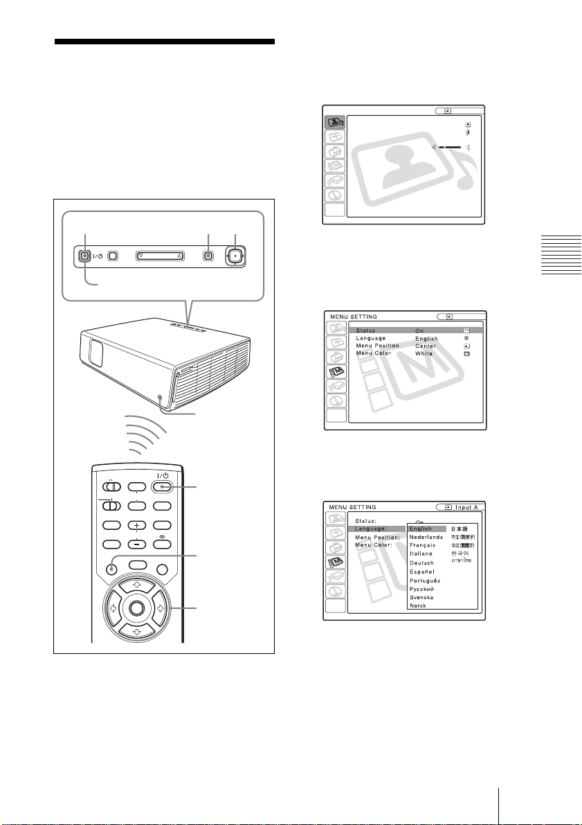
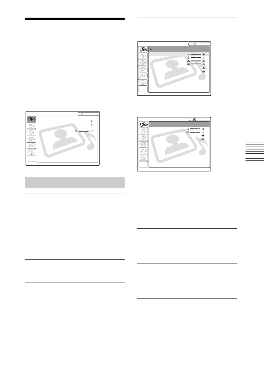
3 Press the MENU key.
The menu appears.
The menu presently selected is shown as
a yellow button.
PICTURE SETTING
Picture Mode: Standard
Adjust Picture...
Volume: 30
Input A
2
ON/STANDBY indicators
1
COMMAND
ON
OFF
PJ NETWORK
MUTING
AUDIO
LENS
VOLUME
APA
MENU/
TAB
FREEZE
PIC
TILT
INPUT
TILT/KEYSTONE
AIR SHOT
4,5,6
3
PUSH
MENUINPUT
ENTER
Front remote
control
detector
2
3
4,5,6
4 Press the M or m key to select the
MENU SETTING menu, then press
the , or ENTER key.
The selected menu appears.
Input A
:
:
:
:
A
5 Press the M or m key to select
“Language,” then press the , or
ENTER key.
Convenient Function
1 Plug the AC power cord into a wall
outlet.
2 Press the I / 1 key to turn on the
projector.
6 Press the M, m, < or , key to select
a language, then press the EN TER
key.
The menu changes to the selected
language.
To clear the menu
Press the MENU key.
The menu disappears automatically if a key
is not pressed for one minute.
Selecting the Menu Language
23
GB
Page 24
Security Lock
The projector is equipped with a security
lock function. When you turn the power of
the projector on, you are required to input
the previously set pas sw or d . If you do not
input the correct password, you will not be
able to project the picture.
Note
You will not be able to use the projector if you
forget your password and the passwor d
administrator is not available. Be please aware
that using the security lock can prevent valid
usage in such cases. It is recommended that
you make a note of th e s elected password.
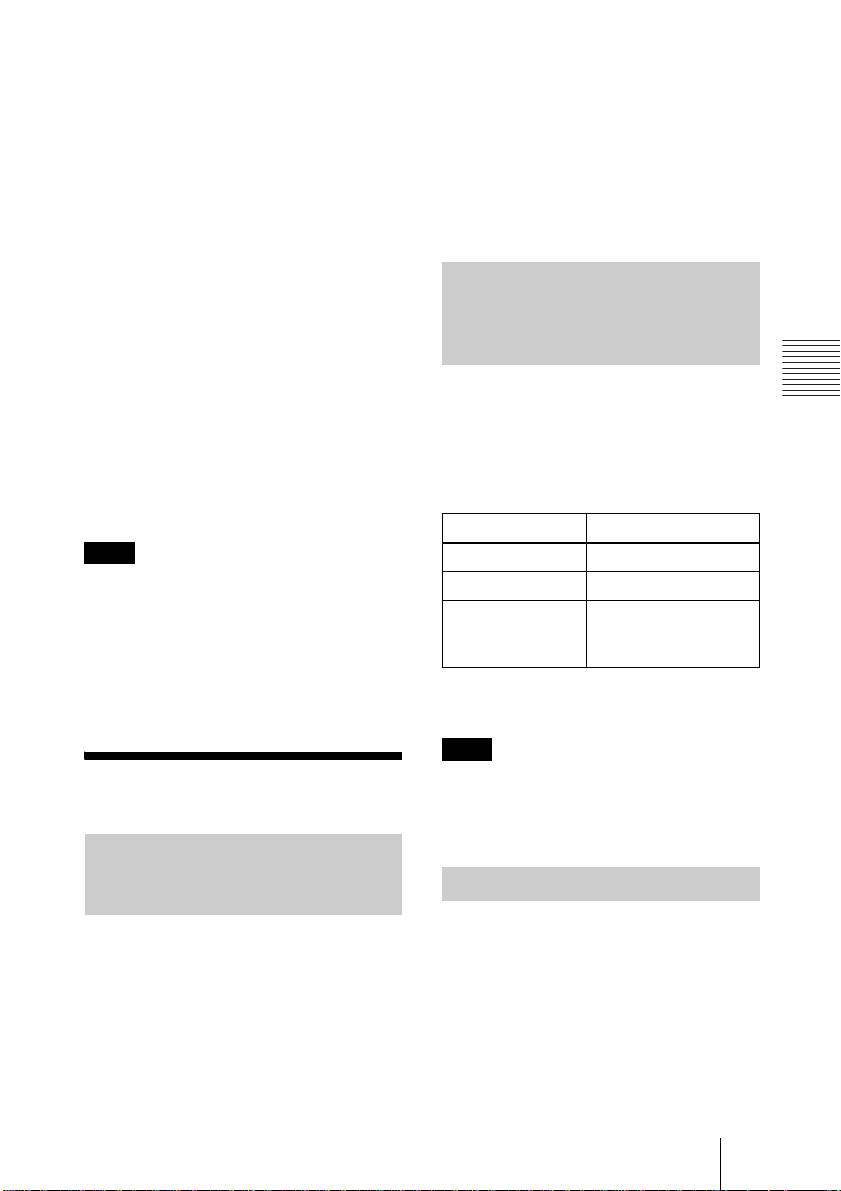
Next, the screen for entering the new
password is displayed. (Enter the
password at this screen even if you want
to keep the current password.)
Enter new password key.
Power-on cannot be performed
without the password.
Use: Cancel: Other key
3 Enter the password again to confirm.
Re-enter new password key.
To use the security lock
1 Press the MENU key and then, in the
INSTALL SETTING menu, turn on
“Security Lock” setting.
the
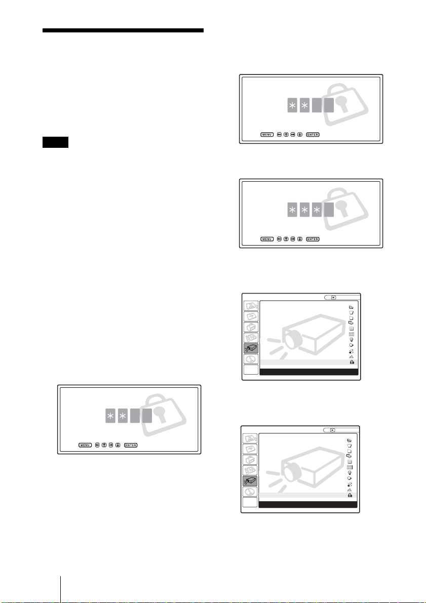
2 Enter the password.
Use the MENU, M/m/</,, and
ENTER keys to enter the four-digit
password. (The default initial password
setting is “ENTER, ENTER, ENTER,
ENTER”. After this is entered you can
put in your own password. Therefore
when you use this function for the first
time, please input “ENTER” four times.)
Enter password key.
Password required for power-on.
Use: Cancel: Other key
Be sure to remember this password.
Use: Cancel: Other key
When the following message is
displayed, the setting for security lock is
completed.
INSTALL SETTING
Tilt...
V Keystone: Auto
Side Shot: 0
Image Flip: Off
Background: Blue
Test Pattern: Off
Lamp Mode: Standard
Lens Control: On
Direct Power On: Off
High Altitude Mode
Security Lock: On
Security Lock enabled!
: Off
Input-A
X
If “Invalid Password! ” is displayed on
the menu screen, perform again from
step 1.
INSTALL SETTING
Tilt...
V Keystone: Auto
Side Shot: 0
Image Flip: Off
Background: Blue
Test Pattern: Off
Lamp Mode: Standard
Lens Control: On
Direct Power On: Off
High Altitude Mode
Security Lock: Off
Invalid Password!
: Off
Input-A
X
GB
24 Security Lock
Page 25
4 Turn the main power off and
disconnect the AC power cord.
The security lock is set to on, then it
becomes effective. The screen for
entering the password is displayed whe n
the power is turned on the next time.
Security certification
When the screen for entering the password is
displayed, enter the password that was set. If
you fail to enter the correct password after
three tries, the projector cannot be used. In
this case, press the I / 1 key to turn off the
power.
To cancel the security lock
1 Press the MENU key, then turn off the
“Security Lock” setting in the
INSTALL SETTING menu.
2 Enter the password.
Enter the password that was set.
Note
If you call the customer service ce nter
because you have forgotten the password,
you will need to be able to verify the
projector’s se rial nu mber an d your ide ntity.
(This process may differ in other countries.)
Once your identity has been confirmed, we
will provide you with the password.
• Smart APA (Auto Pixel Alignment)
Set “Smart APA” in the SET SETTING
menu to “Off.”
• Auto Input Search
Set “Auto Input Search” in the SET
SETTING menu to “Off.”
For details on the menu operations, see
“Using the MENU” on page 27.
Controlling the Computer
Using the Supplied Remote
Commander (When Using the
USB Cable)
When you connect a com puter to the
projector by usi ng the US B ca ble , yo u ca n
control the mouse of the computer using the
Remote Commander.
The R/L CLICK keys and joystick function
as follows.
Key and joystick Function
R CLICK (front) Right button
L CLICK (rear) Left button
Joystick Corresponds with the
movements of the
mouse
For details on USB connection, see “To
connect a computer” on page 17.
Convenient Function
Other Functions
Switching from the Intelligent
Auto-setup Function to
Manual Adjustments
You can switch the following functions of
the Intelligent Auto-setup to manual
adjustments using the men u.
V Keystone correction (correction
•
of trapezoidal distortion)
Set “V Keys tone” in the INSTALL
SETTING menu to “Manual.”
Note
Make sure that nothing obstructs the infrared
beam between the Remote Commander and th e
remote control detector on the projector.
Off & Go Function
If you are leaving the conference roo m
immediately, turn the projector off, and then,
after the lens protector closes and the
powered tilt adjuster is put away in the
projector, you can unplug the AC power
cord. After the AC power cord is unplugged,
the fan runs automatically.
Other Functions
25
GB
Page 26
Notes
• When unplugging the AC power cord, ensure
that the lens protector closes and the powered
tilt adjuster is put away in the projector.
Moving the projector with the powered tilt
adjuster rised may damage the adjuster.
• Turn off the projector according to the
procedure in “Turning off the power”, th en
cool it down when storing the projector in the
carrying case.
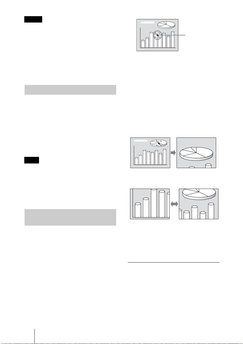
Digital zoom
icon
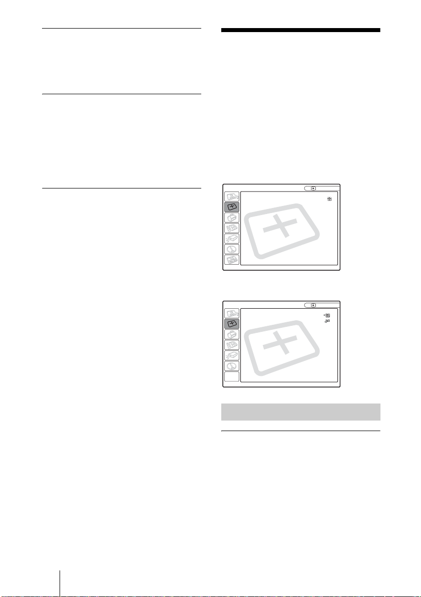
2 Move the icon to the point on the
image you want to enlarge. Use the
arrow key (M/m/</,) to move the
icon.
Direct Power On/Off Function
If you will be using a circuit breake r to tu rn
the power for the entire system on and off,
set the direct power on function to “On.”
When you turn off the power, you can also
just unplug the power cord without pressing
the I / 1 key. The internal circuitry will
cause the fan to automatically operate for a
certain time even after the power cord is
removed.
Note
However, if the unit has been on for less than
15 minutes, th e fan might n ot begin t o turn as a
result of inadequate charging. In that case,
follow the procedure for turning off t he power
as described in “Turning Off the Pow er” on
page 22.
Effective Tools for Your
Presentation
To enlarge the image (Digital Zoom
function)
You can select a point in the i mage to
enlarge. This function works when a sign a l
from a computer is input.
This function does no t wo rk wh e n a vid e o
signal is input.
1 Project a normal image, and press the
D ZOOM + key on the Remote
Commander.
The digital zoom icon appears in the
center of the image.
3 Press the D ZOOM + key again.
The image where the icon is located is
enlarged. The enlargement rati o i s
displayed on the screen for a few
seconds.
By pressing the + key repeatedly, the
image size increases (ratio of
enlargement: max. 4 times.)
Use the arrow key (M/m/</,) to
scroll the enlarged image .
To return the image back to its
original size
Press the D ZOOM – key.
Just pressing the RESET key returns the
image back to its original size immediately.
To freeze the image projected
(Freeze function)
Press the FREEZE key. “Freeze” appears
when the key is pressed. This function wor ks
when a signal from a computer is input.
To restore the original screen, press the
FREEZE key again.
GB
26 Other Functions
Page 27
B Adjustments and Settings Using the Menu
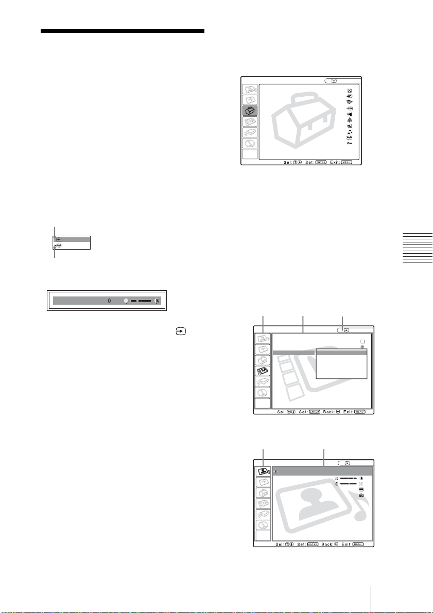
1 Press the MENU key.
Using the MENU
The projector is equipped with an on-screen
menu for making various adjustments and
settings. The setting items are displayed in a
pop-up menu or in a sub menu. If you select
an item name foll owed by dots (...), a s ub
menu with setting items appear. You can
change the tone of the menu display and the
menu languag e displayed in the on-screen
menu.
To change the menu language, see
“Selecting the Menu Languag e” on page 23.
Display items
Input signal indicator
The menu appears.
The menu presently selected is shown as
a yellow button.
SET SETTING
Smart APA: On
Auto Input Search:
Input-A Signal Sel.:
Color System: Auto
Speaker: On
Stand-by Mode: Standard
Power Saving: Off
IR Receiver: Front & Rear
Illumination: On
Panel Key Lock: Off
2 Use the M or m key to select a menu,
then press the , or ENTER key.
The selected menu appears.
3 Select an item.
Video
NTSC 3.58
Input signal setting indicator
Picture adjustment menu
Contrast
Input signal indicator
Shows the selected input ch annel. is
x
displayed when no signal is input. You can
hide this indicator using “Status” in the
MENU SETTING menu.
Input signal setting indicator
For Input A: Shows “Computer,”
“Component” or “Video GBR.”
For Video/S Video input: Shows “Auto” or
the “Color System” setting in the SET
SETTING menu.
Use the M or m key to select the item,
then press the , or ENTER key.
The setting items are displ ayed in a po pup menu or in a sub menu.
Pop-up menu
Setting items
Menu
MENU SETTING
Status:
Language:
Menu Position:
Menu Color:
Sub menu
Menu Setting items
Off
Computer
On
English
Top left
Bottom Left
Center
Top Right
Bottom Right
Input-A
Adjustments and Setting s Using the Menu
Selected input
signal
Input A
A
PICTURE SETTING
ADJUST PICTURE
Contrast: 80
Brightness: 50
Gamma Mode: Graphics
Color Temp: High
Standard
Input A
Using the MENU
27
GB
Page 28

4 Make the setting or adjustment on an
item.
• When changing the adjustment
level:
To increase the number, press the
, key.
To decrease the number, press the m
or < key.
Press the ENTER key to rest ore the
previous screen.
• When changing the setting:
Press the M or m key to change the
setting.
Press the ENTER or < key to restore
the previous screen.
When setting the Menu Language, see
“Selecting the Menu Language” on page 23.
To clear the menu
Press the MENU key.
The menu disappears automatically if a key
is not pressed for one minute.
To reset items that have been
adjusted
Press the RESET key on the Remote
Commander.
“Complete!” appears on the scree n and the
settings appearing on the screen are reset
to their factory preset values.
Items that can be reset are:
• “Contrast,” “Brightness,” “Color,” “Hue”
and “Sharpness” in the Adjust Picture...
menu
• “Dot Phase,” “H Size,” and “Shift” in the
Adjust Signal... menu
M or
About the menu display
You can set the display position of the m enu,
intensity of the ba ckgrou nd pict ure and tone
of the menu items as you like.
For details, see “The MENU SETTING
Menu” on page 34.
About the memory of the settings
The settings are automatically stored in the
projector memory.
If no signal is input
If there is no input signal, “Cannot adjust
this item.” appears on the screen.
GB
28 Using the MENU
Page 29
The PICTURE
SETTING Menu
The PICTURE SETTING menu is used for
adjusting the picture or volume.
Items that cannot be adjusted depending on
the input signal are not displayed in the
menu.
For details on th e unadjustable items, see
page 48.
Adjust Picture...Menu Items
When the video signal is input
PICTURE SETTING
ADJUST PICTURE
Contrast: 80
Brightness: 50
Color: 50
Hue: 50
Sharpness: Middle
Color Temp.:
Standard
Low
Video
PICTURE SETTING
Picture Mode Standard
Adjust Picture...
Volume: 30
Input A
Menu Items
Picture Mode
Selects the picture mode.
Dynamic: Emphasizes the contrast to
produce a “dynamic” picture.
Standard: Normally select this setting. If
the picture has rough ness with the
“Dynamic” setting, this setting reduces
the roughness.
Volume
Adjusts the volume.
Adjust Picture...
The unit can store the setting val ues of the
following sub menu items for each
“Dynamic” or “S ta nd ard” picture mode
separately.
When the computer signal is input
PICTURE SETTING
ADJUST PICTURE
Contrast: 80
Brightness: 50
Gamma Mode: Graphics
Color Temp.: High
Standard
Input A
Contrast
Adjusts the picture contrast. The higher the
setting, the greater the contrast between a
dark portion and a bright portion of the
picture. The lower the setting, the lower the
contrast.
Brightness
Adjusts the picture brightness. The higher
the setting, the brighter the picture. The
lower the setting, the darker the picture.
Color
Adjusts color intensity. The higher the
setting, the greater the intensity. The lower
the setting, the lower the intensity.
Hue
Adjusts color tones. The higher the setting,
the picture becomes greenish. The lower the
setting, the picture becomes purplish.
Adjustments and Setting s Using the Menu
The PICTURE SETTING Menu
29
GB
Page 30
Sharpness
Selects the picture sharpness from among
“High,” “Middle” and “Low.” The “High”
setting makes the picture sharp; the “Low”
setting makes it soft.
Gamma Mode
Selects a gamma correction curve.
Graphics: Improv es the reproduction of
halftones. Pho tos can be reproduced in
natural tones.
Text: Contrasts black and white. Suitable
for images that contain lots of text.
Color Temp.
Adjusts the color temperature.
High: Makes the white color bluish.
Low: Makes the white color reddish.
The INPUT SETTING
Menu
The INPUT SETTING menu is used to
adjust the input signal.
Items that cannot be adjusted depending on
the input signal are not displayed in the
menu.
For details on the unadjustable items, see
page 48.
When the video signal is input
INPUT SETTING
Wide Mode: Off
When the computer signal is input
INPUT SETTING
Adjust Signal...
Scan Converter: On
Video
Input A
GB
30 The INPUT SETTING Menu
MENU Items
Wide Mode
Sets the aspect ratio of the picture. When
inputting 16:9 (squeezed) signal from
equipment s uch as a DVD player , set to
“On”.
Off: When the picture with ratio 4: 3 is input.
On: When the picture with ratio 16:9
(squeezed) is input.
Page 31

Note
Note that if the projector is used for profi t or for
public viewing, modifying the original picture
by switching to the wide mode may constitute
an infringement of the rights of authors or
producers, which are legally protected.
Adjust Signal... Menu Items
(Only when the computer signal is
input)
INPUT SETTING
SIGNAL SETTING
Dot Phase: 24
H Size: 1504
Shift: H: 181 V: 34
Input A
key to adjust the horizontal position and the
M and m key for the vertical position.
Scan Converter
Converts the signal to display the p icture
according to the screen size.
On: Displays the picture according to the
screen size. The picture will lose some
clarity.
Off: Displays the picture while matching
one pixel of input picture ele ment to that
of the LCD. The picture will be clear but
the picture size will be smaller.
Note
When XGA, SXGA or SXGA+ signal is input,
this item will not be displayed.
Dot Phase
Adjusts the dot phase of the LCD panel and
the signal output from a computer.
Adjust the picture further for finer picture
after the picture is adjusted by pressing the
APA key.
Adjust the picture to where it looks clearest.
H Size
Adjusts the horizontal size of picture output
from a connector. The higher the setting, the
larger the horizontal size of the picture. The
lower the setting, the smaller the horizontal
size of the picture. Adjust the setting
according to the dots of the input signal.
For details on the suitable value for the
preset signal s, se e pa ge 49.
Shift
Adjusts the position of the pi cture. H adjusts
the horizontal position of the picture.V
adjusts the vertical position of the picture.
As the setting for H increases, the picture
moves to the right, and as the setting
decreases, the picture moves to the left.
As the setting for V increases, the picture
moves up, and as the setting decreases, the
picture moves down. Use the < or the ,
About the Preset Memor y No.
This projecto r has 45 types of pr eset dat a for
input signals (the preset memory). When a
preset signal is input, the projector
automatically detects the signal type and
recalls the data for the signal from the preset
memory to adjust it to an optimum picture.
The memory number and signal type of that
signal are displayed in the INFORMATION
menu (See page 36). You can also adjust the
preset data through the INPUT SETTING
menu.
This projector has 20 types of user memories
for INPUT-A into which you can save the
setting of the adjusted data for an unpreset
input signal.
When an unpreset signal is input for the first
time, a memory number is displayed as 0.
When you adjust the data of the signal in the
INPUT SETTING menu, it will be
registered to the proj ector. If more than 20
user memories are registered, the newest
memory always overwrites the oldest one.
See the chart on page 49 to find if the signal
is registered to the preset memory.
Adjustments and Setting s Using the Menu
The INPUT SETTING Menu
31
GB
Page 32

Since the data is recalled from the preset
memory about the following signals, you
can use these preset data by adj usting “H
Size.” Make fine adj ustment by adjusting
“Shift.”
Signal Memory No. SIZE
Super Mac-2 23 1312
SGI-1 23 1320
Macintosh 19 " 25 1328
Macintosh 21 " 27 1456
Sony News 36 1708
PC-9821
36 1600
1280 × 1024
WS Sunmicro 3 7 1664
The SET SETTING
Menu
The SET SETTING menu is used for
changing the settings of the projector.
SET SETTING
Smart APA: On
Auto Input Search:
Input-A Signal Sel.:
Color System: Auto
Speaker: On
Stand-by Mode: Standard
Power Saving: Off
IR Receiver: Front & Rear
Illumination: On
Panel Key Lock: Off
Off
Computer
Input-A
Note
When the aspect ratio of input signal is other
than 4:3, a part of the screen is displayed in
black.
Menu Items
Smart APA
Activates or deactivates the Smart APA
On: Normally select this setting. When a
signal is input from a c omputer, the APA
functions automatically so that the
picture can be seen clearly. Once the
specified input signal has been adjusted
by the “Smart APA,” it will not be
readjusted even when the cable is
disconnected and connected again or the
input channel is changed. You can adjust
the picture by pressi ng APA key on the
Remote Commander even if the “Smart
APA” set to “On.”
Off: The APA functions when you press the
APA key on the Remote Commander.
Notes
• Press the A P A key when the full image is
displayed on the scr een. If the projected
image includes much black portion around it,
the APA function will not work properly and
some parts of the image may not be displayed
on the screen.
• You can cancel the adjustment by pressin g
the APA key again w hile “Adjusting”
appears on the scre en.
• The picture may not be a d j us te d properly
depending on the kinds of input signals.
1)
.
GB
32 The SET SETTING Menu
Page 33

• Adjust the items “Dot Phase, ” “H Size” and
“Shift” in the INPUT SETTING menu when
you adjust the picture manually.
1)The APA (Auto Pixel Alignment)
automatica lly adjusts “Dot Phase ,” “H Size”
and “Shift” in the INPUT SETTING menu
for the input signa l f ro m a computer.
Stand-by Mode
You can lower the power consumption in
standby mode .
Standard: Normally, select this position.
Low: Select this position when you want to
lower the power c onsumption in st andby
mode.
Auto Input Search
Normally set to “Off.”
When set to “On,” the projector detects input
signals in the following order: Input-A/
Input-B/Video/S-Video. It indicates the
input channel when the power is tu rned on or
the INPUT key is pressed.
Input-A Signal Sel.
Selects the computer, component or video
GBR signal input fro m the INPUT A
connector.
Note
If the setting is not correct, the color of the
picture becom es st range or “Please che ck
Input-A Signal Sel.” appears on the screen and
the picture is not displayed.
Color System
Selects the color system of the input signal.
If you select “Auto,” the projector detects
the color system of the input signal
automatically. If the picture is distorted or
colorless, select the color system ac cording
to the input signal.
When the color system of the input signal is
PAL60, select “PAL.” If “Auto” is selected,
the color system cannot be detected.
Speaker
Set to “Off” to cut off the sound of the
internal speakers. When set to “Off,”
“Speaker: Off” appears on the screen when
you turn on the power.
Power Saving
When set to “On,” the projector goes into
power saving mode if no signal is input for
10 minutes. Although the lamp goes out, the
cooling fan keeps running. The power
saving mode is canceled when a sig nal is
input or any key is pressed. In power saving
mode, any key does not function for the first
60 seconds after the lamp goes out.
IR Receiver
Selects the remote control detectors (IR
receiver) on the front and rear of the
projector.
Front&Rear: Activates both the front and
rear detectors.
Front: Activates the front detector only.
Rear: Activates the rear detector only.
Illumination
Selects whether the SONY logo on the top
panel of the projector lights when the
projector is on. Normally, this setting is
“On”. If you want complete darkness or if
the illuminated logo is a distra c tion, change
this setting to “Off”.
Panel Key Lock
Locks all the control panel keys on the top
and side panels of the pr ojector so that the
projector can be operated only w ith the
Remote Commander.
To lock the control panel keys, set to “On.”
When it is set to “On,” keeping the I/1 key
on the control panel pr essed for 10 seconds
turns the projector on when it is in standby
mode, and turns the projector to stand by
mode when the power is on . If you keep
pressing the MENU ke y f or ab out 10
seconds when the power is on, the lock will
Adjustments and Setting s Using the Menu
The SET SETTING Menu
33
GB
Page 34

be released and “Panel Key Lock” is
automatically set to “Off.”
Note
The function can be controlled with the
REMOTE RS-232C connector.
The MENU SETTING
Menu
The MENU SETTING menu is used for
changing the me n u dis p la ys .
MENU SETTING
Status: On
Language: English
Menu Position: Center
Menu Color: White
Menu Items
Status (on-screen display)
Sets up the on-screen display.
On: Shows all of the on-screen displays.
Off: Turns off the on-screen displays except
for the menus, a message when turning
off the power, and warning messages.
Input A
A
GB
34 The MENU SETTING Menu
Language
Selects the language used in the menu and
on-screen displays. Available languages are:
English, Nederlands, Français, It al iano,
Deutsch, Español, Português, ,
Svenska, Norsk, , ,
, and .
Menu Position
Selects the disp lay position of the me nu
from “Top Left,” “Bottom Left,” “Center,”
“Top Right” and “Bottom Right”.
Menu Color
Selects the tone of the menu display from
“Black” or “White”.
Page 35

The INSTALL
SETTING Menu
Side Shot
Corrects the horizontal trapezoidal
distortion of the picture using the < or ,
key on the Remote Commander.
The INSTALL SETTING menu is used for
changing the settings of the projector.
INSTALL SETTING
Tilt...
V Keystone: Auto
Side Shot: 0
Image Flip: Off
Background: Blue
Test Pattern: Off
Lamp Mode: Standard
Lens Control: On
Direct Power On: Off
High Altitude Mode
Security Lock: Off
: Off
Input-A
Menu Items
Tilt...
Adjusts the position (height) of the pro jected
picture. Pressing the f on the TILT
adjustment key o r M/, key on the Remote
Commander, the more the proje ctor tilts and
the higher the position of the picture.
Pressing the F on the TILT adjustment key
or m/< key on the Remote Commander,
the less the projector tilts and the lower the
position of the picture.
V Keystone
Corrects the trapezoidal distortion caused by
the projection angle. Select “Auto” for
automatic correction, or “Manual” for
manual correction using the < or , key.
When the bottom of the trapezoid is
longer than the top : Sets a lower
value.
When the top of the trapezoid is longer
than the bottom : Sets a higher
value.
Note
The auto V Keystone adjustment may not
correct the trapezoidal distortion perfectly,
depending on t he room temperature or the
screen angle.
When the right side is longer tha n the
left side ( )
Set to a higher value (+ direction).
When the left side is longer than the
right side ( )
Set to a lower value (– direction).
Set the adjustment level to “0” if you want t o
adjust the picture more widely using “V
Keystone” only.
Note
Even when projecting using “Side Shot”, the
four sides of a picture may sometimes not be
parallel to the respective sides o f a s creen
frame.
Adjustments and Setting s Using the Menu
Image Flip
Flips the image on the screen horizontally
and/or vertically.
Off: The image does not flip.
HV: Flips the image horizontally and
vertically.
H: Flips the image horizontally.
V: Flips the image vertically.
Background
Select the background col or of t he screen
when no signal is input to the projector.
Select “Black” or “Blue”.
Normally, set to “Blue.”
Test Pattern
The factory setting is “Off.”
When set to “On,” a test pattern is d isplayed
on the screen during the “Lens Zoom”
adjustment, “Lens Focus,” “Si de Shot” or
“V Keystone.” If you do not want to display
a test pattern, set to “Off”.
Lamp Mode
Sets the lamp brightness in the projection.
The INSTALL SETTING Menu
35
GB
Page 36

High: Illuminate s the project ed image
brightly.
Standard: Reduc e s f a n noise and power
consumption. The brightness of the
projected image will be lower compared
with the “High” setting.
Direct Power On
Set to “On” if you are using a circuit breaker
to turn the power on/off the entire system.
You can turn off the power just by
unplugging the power cord without pressing
the I/1 key.
Lens Control
When set to “Off,” the LENS (FOCUS,
ZOOM) key on the Remote Commander,
and the FOCUS and ZOOM keys on the
projector do not function.
High Altitude Mode
The factory setting is “Off.”
Set to “On” when the projector is used at an
altitude of 1,500 m or highe r .
Security Lock
Turns on the projector’s security lock
function.
Off: Turns off the security lock function.
On: Turns on the security lock function,
which locks the projector once a
password has been set.
For details, see “Security Lock” on page 24.
The INFORMATION
Menu
The INFORMATION menu displays the
horizontal and vertical frequencies of the
input signal and the used time of the lamp.
INFORMATION
fH: 48.47kHz
fV: 60.00Hz
No.23
1024x768
Lamp Timer: 0H
Menu Items
fH
Displays the horizontal frequency of the
input signal.
The displayed value is approximat e.
fV
Displays the vertical frequency of the input
signal.
The displayed value is approximat e.
Lamp Timer
Indicates how long the lamp has been tu rned
on.
Input A
Memory
number of
an input
signal
Signal
type
GB
36 The INFORMATION Menu
Note
These only display on the screen. You cannot
alter the display.
Page 37

B Maintenance
Maintenance
projector o v er so you can see its
underside.
Replacing the Lamp
Replace the lamp with a new one in the
following case.
• When the lamp has burnt out or dims
• “Please replace the LAMP.” appears on
the screen
• The LAMP/COVER indicator lights up
The lamp life varies depending o n
conditions of use.
Use LMP-C190 Projector Lamp as the
replacement lamp.
Use of any other lamps than the LMP-C190
may cause damage of the projector.
Caution
The lamp becomes a high temperature after
turning off the projector with the I / 1 key. If
you touch the lam p, you may scald your
finger. When you replace the lamp, wait for
at least an hour for the lamp to cool.
Notes
• If the lamp breaks, consult with qualified
Sony personnel.
• Pull out the lamp by holding the handle. If
you touch the lamp, yo u m ay be burned or
injured.
• When removing the lamp, make sure it
remains ho rizontal, then pull s traight up. Do
not tilt the lamp. If you pull out the lamp
while tilted and if the lamp bre aks, the pieces
may scatter, causing injury.
Note
Be sure that the projector is stable after
turning it over.
3 Open the lamp cover by loosening a
screw with the Phillips screwdriver.
Note
For safety sake, do not loosen any other
screws.
Maintenance
1 Turn off the projector, and disconnect
the AC power cord from the AC
outlet.
Note
When replacing th e l am p after using the
projector, wait for at least an hour for the
lamp to cool.
2 Place a protective sheet (cloth)
beneath the projector. Turn the
Maintenance
37
GB
Page 38

4 Loosen the two screws on the lamp
unit with the Phillips screwdriver
(1). Fold out the handle (2), then
pull out the lamp unit by the handle
(3).
Handle
5 Insert the new lamp all the way in until
it is securely in place (1). Tighten the
two screws (2). Hold down the
handle to replace (3).
• The power will not turn on if the lamp is
not secured properly.
6 Close the lamp cover and tighten a
screw.
7 Turn the projector back over.
8 Connect the power cord.
The ON/STANDBY indicator around
the I/1 key lights in red.
9 Press the following keys on the
Remote Commander in the following
order for less than five seconds each:
RESET, <, ,, ENTER.
Note
Do not put your hands into the lamp
replacement spot, or not fall any liquid or
object into it to avoid elect ri cal shock or fi re.
Disposal of the used lamp
For the custmers in the USA
This product contains mercury. Disposal of
this product may be regulated if sold in the
United Stat es . For disposal or rec ycling
information, please contact yo ur loc a l
authorities or Electronics Industries Allianc e
(www.eiae.org http://www.eiae.org).
Notes
• Be careful not to touch the glass surface
of the lamp.
GB
38 Maintenance
Cleaning th e Air Filter
The air filter should be cleaned every 1000
hours.
Remove dust from the outside of the
ventilation holes with a vacuum cleaner.
1000 hours are approximate. This value
varies depending on the environment or
how the projector is used.
Page 39

When it becomes difficult to remove the dust
from the filter with a vacuum cleaner,
remove the air filter and wash it.
1 Turn off the power a nd unplug the
power cord.
2 Place a protective sheet (cloth)
beneath the projector and turn the
projector over.
3 Remove the air filter cover.
4 Remove the air filter.
• If the dust cannot be rem oved from the air
filter, replace the air filter with the supplied
new one.
• Be sure to attach the air filt er cover firmly;
the power will not be turned o n if it is not
closed securely.
• The air filter has a face and a reverse side.
Place the air filter so that it fits in a notch on
the air filter cove r.
Maintenance
5 Wash the air filter with a mild
detergent solution and dry it in a
shaded place.
6 Attach the air filter and replace the
cover.
Notes
• If you ne glect to clean the air filter, dust
may accumulate, cl ogging it. As a result,
the temperature may rise inside the unit,
leading to a possible malfunction or fire.
Maintenance
39
GB
Page 40

Troubleshooting
If the projector appears to be operating erratically, try to diagnose and correct the problem
using the following instructions. If the problem persists, consult with qualified Sony
personnel.
Power
Symptom Cause and Remedy
The power is not turned on. • The powe r has been turned off and on with the I / 1 key at a short
Both the LAMP/COVER
and TEMP/FAN indicators
light up.
The powered tilt adjuster
and the lens protec to r do
not close.
The lens protector cannot
open.
interval.
c Wait for about 45 seconds before turning on the power
(see page 22).
• The lam p cover is detached.
c Close the lamp cover securely (see page 38).
• The air filter cover is detached.
c Close the air filter cover securely (see page 39).
• The electrical system breaks down.
c Consult with qualified Sony personnel.
• The AC power cord is un plugged with the power of the projector
turned on.
c Connect the power cord to the AC outlet again, turn on the
power of the projector, then turn it off.
• The electrical system breaks down.
c Consult with qualified Sony personnel. If it is necessary to use
the projector in case of emergency, slide the lens protector by
hand, and then press th e I/
1 key. You can use the projecto r.
GB
40 Troubleshooting
Page 41

Picture
Symptom Cause and Remedy
No picture. • Cable i s di s connected or the connections are wrong.
The picture is noisy. • Noise may appear on the backgr ound depending on the
The picture from INPUT A
connector is col o r ed
strange.
“Please check Input-A
Signal Sel.” appears in
spite of inputting the
correct sig nal from INPUT
A.
On-screen display does not
appear.
Color balance is incorrect. • Picture has not been adjusted properly.
The picture is too dar k. • Contra st or brightness has not been adjusted properly.
c Check that the proper connections have been mad e
(see page 17).
• The co nnections are wrong.
c This projector is compatible with a DDC2B (Digital Data
Channel 2B). If your computer is compatible with a DDC, turn
the projector on according to the following procedures.
1 Connect the projector to the com puter.
2 Turn the projector on.
3 Start the computer.
• Input selection is incorrect.
c Select the input source correctly using the INPUT key
(see page 20).
• The picture is muted.
c Press the PIC MUTING key to release the picture muting (see
page 14).
• The computer signal is not set to output to an external monitor or
set to output both to an external monitor and a LCD monitor of a
computer.
c Set the computer signal to output only to an external monitor
(see page 18).
combination of th e numbers of dot input fr om the connector and
numbers of pixel on the LCD panel.
c Change the desktop pattern on the connected computer .
• Setting of “Input-A Signal Sel.” in the SET SETTIN G me nu is
incorrect.
c Select “Computer,” “Video GBR” or “Component” correctly
according to the input signal (see page 33).
• Setting of “Input-A Signal Sel.” in the SET SETTIN G me nu is
incorrect.
c Select “Computer,” “Video GBR” or “Component” correctly
according to the input signal (see page 33).
• “Status” in the MENU SETTI NG me nu has been set to “Off.”
c Set “Status” in the MENU SETTING menu to “On” (see page
34).
c Adjust the pict ure (see page 29).
• Projector is set to wrong color system.
c Set “Color System” in the SET SETTING menu to match the
color system being i nput (see page 33).
c Adjust the contrast or brightness in the “Adjust Picture...” menu
properly (see page 29).
• The lamp has burnt or dims.
c Replace the lamp with a new one (see page 37).
Maintenance
Troubleshooting
41
GB
Page 42

Symptom Cause and Remedy
The picture is not clear. • Picture is out of focus.
The image ext ends beyond
the screen.
The picture flickers. • “Dot Phase” in the INPUT SE TTI N G m enu has not been adjusted
c Adjust the focus (see page 21).
• Conde ns ation has occurred on t he lens.
c Leave the projector for about two hours with the power on.
• The APA key is pressed although there are black edges around the
image.
c Display the full image on the screen and press the APA key.
c Adjust “Shift” in th e IN PUT SETTING menu pr operly (see
page 31).
properly.
c Adjust “Dot Phase” in the INPUT SETTING menu properly
(see page 31).
Sound
Symptom Cause and Remedy
No sound. • Cable is di sconnected or the connections are wrong.
c Check that the proper connections have been made (see page
17).
• The audio connecting cable is incorrect.
c Use a no-resistance stereo audio cable (see page 17).
• The so und is muted.
c Press the AUDIO MUTING ke y to relea se the audio mutin g (see
page 14).
• The sound is not adjusted properly.
c Adjust the sound with the VOLUME +/– key on the Remote
Commander or adjust “Volume” in the PICTURE SETTING
menu (see page 29).
• “Sp eaker” is set to “Off.”
c Set “Speaker” in th e SET SETTING menu to “O n” (see page
33).
Remote Commander
Symptom Cause and Remedy
The Remote Commander
does not work.
The computer cann ot be
controlled with the Remote
Commander.
GB
42 Troubleshooting
• The Remote Commander batteries are dead.
c Replace with a new battery (see page 15).
• The COMMAND ON/OFF switch is set to OFF.
c Set to ON.
• The PJ/NETWORK selector switch is set to NETWORK.
c Set to PJ.
• The USB cable is not connected.
c Connect the projector to the computer using the USB cable.
Page 43

Others
Symptom Cause and Remedy
The LAMP/COVER
indicator flashes.
The LAMP/COVER
indicator lights up.
The TEMP/FAN indicator
flashes.
The TEMP/FAN indicator
lights up.
Both the LAMP/C OVER
and TEMP/F AN indicators
light up.
The control panel keys do
not function .
• The lamp cover or the air filter cover is detached.
c Attach the cover se curely (see pages 38 and 39) .
• The lens protector does not open due to a problem.
c Slide the lens prot ector by hand, and then press t he I/
• The lamp has reached the end of its life.
c Replace the lam p (see page 37).
• The lamp becomes a high temperature.
c Wait for 60 seconds to cool down the lamp and turn on the
power again.
• The fan is broken.
c Consult with qual ified So ny per so nnel.
• The int er nal temperature is unusually high.
c Check to see if nothing is blocking the ventil at i on holes.
• The proj ector is used at a high alti t ude.
c Ensure that “High Altitude Mode” in the INSTALL SETTING
menu is set to “On.”
• The electrical system breaks down.
c Consult with qual ified So ny per so nnel.
• The control panel keys are locked.
c Unlock the control panel keys (see page 33).
1 key.
Warning Messages
Use the list below to check the meaning of the messages displayed on the screen.
Message Meaning and Re m edy
High temp.!
Probably use in high
altitude. Switch to high
altitude mod e on? Yes V
No v
High temp.!
Lamp off in 1 min.
Frequency is out of range! • This input signal cannot be projected as the frequency is out of the
Please check Input -A
Signal Sel.
• Internal temperature is too h ig h.
c When using the projector at an altitude of 1,500 m or higher, set
“High Altitude Mode” in the INSTALL SETTING menu to
“On” (see page 36).
c If this message appears on the screen when using the projector
at normal altitudes, check to see if anythi ng is blocking the
ventilation holes (exh aust).
• Internal temperature is too h ig h.
c Turn off the power.
c Check to see if nothing is blocking the ventil at i on holes.
acceptable range of the projector.
c Input a signal that is within the range of the frequency.
• The resolution setting of the output signal of a computer is too
high.
c Set the setting of output to XGA (see page 17).
• You have input RGB signal from the comp ut er w hen “Input-A
Signal Sel.” in the SET SETTING menu is set to “Component.”
c Set “Input-A Signal Sel.” correctly (see page 33).
Troubleshooting
43
Maintenance
GB
Page 44

Message Meaning and Remedy
Please replace the LAMP. • It is time to replace the lamp.
c Replace the lamp .
Caution Messages
Use the list below to check the meaning of the messages displayed on the screen.
Message Meaning and Remedy
Not applicable! • You have pressed the wrong key.
The panel keys are locked ! • “Panel Key Lock” in the INSTALL SETTING menu is set to “On.”
c Press the appropriate key.
c All the keys on the cont rol panel of the proje ct or are locked.
Operate the projector with the keys on the Remote Commander
(see page 33).
GB
44 Troubleshooting
Page 45

B Others
Specifications
Optical characteristics
Projection system
LCD panel 0.79-inch XGA panel, about
Lens 1.2 times zoom lens (powered)
Lamp 190 W UHP
Projection pictur e siz e
Light output ANSI lumen
Throwing distance (Whe n pl ac ing on the floor)
There may be a slight difference between the
actual value and the design value shown above.
1) ANSI lumen is a measuring method of
American National Standard IT 7.228.
Electrical characteristics
Color system NTSC3.58/PAL/SECAM/
3 LCD panels, 1 lens, projecti on
system
2,360,000 pixels (786,432
pixels × 3)
f 23.5 to 28.2 mm/F1.6 to 1.78
40 to 300 inches (meas ured
diagonally)
(When the Lamp Mode is set to
“High”)
When the XGA signal is input
40-inch: 1.2 to 1.4 m
(3.9 to 4.6 feet)
60-inch: 1.8 to 2.0 m
(5.9 to 6.6 feet)
80-inch: 2.4 to 2.7 m
(7.9 to 8.9 feet)
100-inch: 3.0 to 3.4 m
(9.8 to 11.2 feet)
120-inch: 3.6 to 4.1 m
(11.8 to 13.5 feet)
150-inch: 4.5 to 5.2 m
(14.8 to 17.1 feet)
180-inch: 5.4 to 6.2 m
(17.7 to 20.3 feet)
200-inch: 6.0 to 6.9 m
(19.7 to 22.6 feet)
250-inch: 7.5 to 8.7 m
(24.6 to 28.5 feet)
300-inch: 9.0 to 10.4 m
(29.5 to 34.1 feet)
NTSC
PAL60 system, switched
automatically/manually
(NTSC
when playing back a vide o
1)
3000 lm
4.43/PAL-M/PAL-N/
4.43 is the color system used
recorded on NTSC on a
4.43 system VCR.)
Resolution 750 horizontal TV lines (Video
Acceptable compute r sign als
1) Set the resolution and the frequency of the
signal of the connected computer w ithin the
range of acceptable preset sign als of the
projector.
Applicable video signals
Speaker Monaural speaker system, 40 × 20
NTSC
input)
1,024 × 768 dots (RGB input)
fH: 19 to 92 kHz
fV: 48 to 92 Hz
(Maximum input signal resolution:
SXGA+ 1400 × 1050
fV: 60 Hz
15 k RGB 50/60 Hz, Progressive
component 50/60 Hz, DTV
(480/60i, 575/50i, 480/60p,
575/50p, 540/60p, 720/60 p,
720/50p, 1080/60i, 1080/ 50i),
Composite video, Y/C video
mm (1
1 W
1)
5
/8 × 13/16 inches), max.
Input/Output
Video input VIDEO: pho no type
INPUT A HD D-sub15-pin (female)
Composite video: 1 Vp-p ±2 dB
sync negative (75 ohms
terminated)
S VIDEO: Y/C mini DIN 4-pin
type
Y (luminance): 1 Vp-p ±2 dB
sync negative (75 ohms
terminated)
C (chrominance): burst
0.286 Vp-p ±2 dB (NTSC)
(75 ohms terminated),
burst 0.3 Vp-p ±2 dB (PAL)
(75 ohms terminated)
AUDIO: stereo minijack
500 mVrms, impedance more
than 47 kilohms
Analog RGB/co mp onent:
R/R-Y: 0.7 Vp-p ±2 dB
(75 ohms terminated)
G: 0.7 Vp-p ±2 dB
(75 ohms terminated)
G with sync/Y: 1 Vp-p ±2 dB
sync negative
(75 ohms terminated)
B/B-Y: 0.7 Vp-p ±2 dB
(75 ohms terminated)
SYNC/HD:
Others
45Specifications
Page 46

Composite sync input: 1-5 Vp-p
high impedance, positive/
negative
Horizont al sync in put: 1-5 Vp -p
high impedance, positive/
negative
VD:
Vertical sync input: 1-5 Vp-p
high impedance, positive/
negative
AUDIO: Stereo minijack
(Common INPUT A/B)
500 mVrms, impedance more
than 47 kilohms
INPUT B Analog RGB: HD D-sub 15-pin
(female)
R: 0.7 Vp-p ±2 dB (75 ohms
terminated)
G: 0.7 Vp-p ±2 dB (75 ohms
terminated)
G with sync: 1 Vp-p ±2 dB sync
negative (75 ohms terminated)
B: 0.7 Vp-p ±2 dB (75 ohms
terminated)
SYNC HD: Composite sync
input: 1 - 5 Vp-p high
impedance, positive/nega ti ve
Horizontal sync input: 1 - 5 Vpp high impedance, positive/
negative
VD: Vertical sync input: 1 - 5
Vp-p high impedance, positive/
negative
USB Up (female) × 1
OUTPUT MONITOR OUT: HD D-sub 15-
pin (female)
R, G, B: Gain Unity: 75 ohms
SYNC/HD, VD: 4 Vp-p (open),
1 Vp-p (75 ohms)
AUDIO OUT (variable out):
Stereo minijack
max. 1 Vrms, when an input
signal is 500 mVrms,
impedance less than 5 kilohms
REMOTE RS-232C: D-sub 9 pin
Safety regulations
UL60950, cUL (CSA No. 60950),
FCC Class B, IC Class B,
DEMKO (EN60950), CE
(LVD, EMC), C-Tick
Power requirements
Power consumption
Heat dissipation
Operating temperature
Operatin g humidity
Storage temperature
Storage humidity
Supplied accessories
Design and spec ifications are subject to change
without notice.
AC 100 to 240 V, 2.8 to 1.2 A, 50/
60 Hz
Max. 280 W
(in standby (standard): 5 W
in standby (low): 0.5 W)
921.3 BTU
0°C to 35°C (32°F to 95°F)
35% to 85% (no condensatio n)
–20°C to 60°C (–4°F to 140°F)
10% to 90%
Remote Commander (1)
Size AA (R6) batteries (2)
HD D-sub 15 pin cable (2 m) (1)
(1-791-992-21)
USB cable A type - B type (1)
(1-790-081-31)
Carrying case (1)
AC power cord (1)
Air filter (for replacement) (1)
Operating Instructions (1)
Quick Refer e n ce Card (1)
Security Label (1)
Optional accessories
Projector Lamp
LMP-C190
Signal Cable SMF-402 (HD D-sub 15-pin
Some of the items may not be avai l able in some
areas. For details, please consult your nearest
Sony office.
(for replacement)
(male) y 3 × phono type
(male))
General
Dimensions 328 × 92.6 × 283.8 mm (13 ×
Mass Approx. 3.8 kg (8 lb 6 oz)
GB
46 Specifications
3
/4 × 11 1/4 inches) (w/h/d )
3
(without the projection part s)
Page 47

Pin assignment
INPUT A/B connector (HD D-sub 15pin, female)
1R/R-Y 9N.C.
2 G/Y 10 GND
3 B/B-Y 11 GND
4 GND 12 DDC/SDA
5 GND 13 HD/C.Sync
6GND (R)14VD
7 GND (G) 15 DDC/SCL
8GND (B)
RS-232C connector (D-sub 9 pin,
female)
1DCD 6DSR
2RXDA 7RTS
3TXDA 8CTS
4DTR 9RI
5GND
Others
47Specifications
Page 48

Input signals and adjustable/setting items
Adjust Picture... menu
Item Input signal
Video or S video
(Y/C)
Contrast
Brightness
Color
Hue
Sharpness
Gamma Mode – – z
Color Temp.
Vol u me
zzzzz
zzzzz
zzz
z (NTSC 3.58/
4.43 only)
zzz
zzzzz
zzzzz
Component Video GBR Computer B&W
––––
*
z : Adjustable/can be set
– : Not adjustable/cannot be set
*: Preset memory no. 3, 4 only
INPUT SETTING menu
Item Input signal
Video or S video
(Y/C)
Dot Phase–––
H Size –
Shift
Scan Converter – – –
Wide Mode
–
zz*2z
Component Video GBR Computer B&W
*1
z
*1
z
–
– z –
z : Adjustable/can be set
– : Not adjustable/cannot be set
*1: Expect preset memory no.3, 4
*2: Expect preset m em ory no.5, 45, 47, 48, 50
––
–
z
z
z
z
( lower than
SVGA)
–
z
–
–
–
–
z
GB
48 Specifications
Page 49

Preset signals
Memory
No.
1 Video 60 Hz 60 Hz 15.734 59.940
2 Video 50 Hz 50 Hz 15.625 50.000
3 480/60i 480/60i 15.734 59.940 S on G/Y or
4 575/50i 575/50i 15.625 50.000 S on G/Y or
5 1080/60i 1035/60i, 1080/60i 33.750 60.000
6 640 × 350 VGA mode 1 31.469 70.086 H -p os, V- neg 800
7 VGA VESA 85 Hz 37.861 85.080 H-pos, V-neg 832
8 640 × 400 PC-9801 Norm al 24.823 56.416 H -n eg, V-neg 848
9 VGA mode 2 31.469 70.086 H-neg, V-pos 800
10 VGA VESA 85 Hz 37.861 85.080 H-neg, V-pos 832
11 640 × 480 VGA mode 3 31.469 59.940 H-neg, V-neg 800
12 Macintosh 13" 35.000 66.667 H-neg, V-neg 864
13 VGA VESA 72 Hz 37.861 72.809 H-neg, V-neg 832
14 VGA VESA 75 Hz 37.500 75.000 H-neg V-neg 840
15 VGA VESA 85 Hz 43.269 85.008 H-neg V-neg 832
16 800 × 600 SVGA VE SA 56 Hz 35.156 56.250 H-p os , V-pos 1024
17 SVGA VESA 60 Hz 37.879 60.317 H-pos, V -pos 1056
18 SVGA VESA 72 Hz 48.077 72.188 H-pos, V -pos 1040
19 SVGA VESA 75 Hz 46.875 75.000 H-pos, V -pos 1056
20 SVGA VESA 85 Hz 53.674 85.061 H-pos, V -pos 1048
21 832 × 624 Mac in tosh 16" 49.724 74.550 H-neg, V-neg 1152
22* 1024 × 768 XGA VESA 43 Hz 35.524 86.958 H-pos, V-pos 1264
23 XGA VESA 60 Hz 48.363 60.004 H-neg V-neg 1344
24 XGA VESA 70 Hz 56.476 69.955 H-neg V-neg 1328
25 XGA VESA 75 Hz 60.023 75.029 H-pos, V-pos 1312
26 XGA VESA 85 Hz 68.677 84.997 H-pos, V-pos 1376
27 1152 × 8 64 SXGA VESA 70 Hz 63.995 70.019 H-pos, V-pos 1472
28 SXGA VESA 75 Hz 67.500 75.000 H-pos, V-pos 1600
29 SXGA VESA 85 Hz 77.487 85.057 H-pos, V-pos 1568
30 1152 × 900 Sunmicro LO 61.795 65.960 H-neg, V-neg 1504
31 Sunmicro HI 71.7 13 76.047 C om posite Sync 1472
Preset signal fH (kHz) fV (Hz) Sync SIZE
Composite Sync
Composite Sync
Others
49Specifications
Page 50

Memory
Preset signal fH (kHz) fV (Hz) Sync SIZE
No.
32 1280 × 960 S XGA VES A 60 Hz 60.000 60.000 H-pos, V-pos 1800
33 SXGA VESA 75 Hz 75.000 75.000 H-pos, V-pos 1728
34* 1280 × 1024 S XGA VES A 43 Hz 46.433 86.872 H-pos, V-pos 1696
35 SGI-5 53.316 50.062 S on G 1680
36 SXGA VESA 60 Hz 63.974 60.013 H-pos, V-pos 1696
37 SXGA VESA 75 Hz 79.976 75.025 H-pos, V-pos 1688
38 SXGA VESA 85 Hz 91.146 85.024 H-pos, V-pos 1476
43 480/60p 480/60p
31.470 60.000 S on G
(Progressive
component
44 575/50p 575/50p
31.250 50.000 S on G
(Progressive
component
45 1080/50i 1080/50i 28.130 50.000
47 720/60p 720/60p 45.000 60.000
48 720/50p 720/50p 37.500 50.000
50 540/60p 540/60p 33.750 60.000
52 1400 × 1050 SXGA+ 60 Hz 63.981 60.020 H-pos, V-pos 1688
Notes
• When a signal other than the preset signals shown above is input, the picture may not
appear properl y.
• Memory No. 22 and 34 show the interlace signal.
• When a SXGA+ signal is input, the image may extend be yond the screen. In this case,
input a signal with no black edges around the image, and disconnect and reconnect the
cable or select the input signal by pressing INPUT key.
GB
50 Specifications
Page 51

Warning on power connection
Use the supplied power cord when you use the projector in your country.
Otherwise, use a proper power cord meeting the following specification.
The United States,
Canada
Plug type VM0233 290B YP-12A COX-07 –
Female end VM0089 386A YC-13B COX-02 VM0310B YC-13
Cord type SJT SJT H05VV-F H05VV-F N13237/CO-228 VCTF
Rated Voltage &
Current
Safety approval UL/CSA UL/CSA VDE VDE VDE DENAN
Cord length
(max.)
10A/
125V
4.5 m (177
1)
Use the correct plug for your country.
10A/
125V
1
/4 inches) –
Continental Europe UK, Ireland,
10A/
250V
10A/
250V
Australia, New
Zealand
1)
10A/250V 7A/125V
Japan
YP332
Others
51Specifications
Page 52

Installation Diagr am
Floor Installation (Front Projection)
Distance between the fron t of the cabinet
and the center of the lens
Wall
x
Center of the
screen
Front of the
cabinet
Center of the lens
Front of the lens
11
/16 )
(
17.4
c
Floor
b
a
Unit : mm (inches)
This section describes the examples of installing the projector on a desk, etc.
See the chart on page 53 concerning the installation measurements.
The alphabetical letters in the illustration indicate the distances below.
a: distance betwee n the screen and the center of the lens
b: distance between the floor and the center of the lens
c: distance between the floor and the bottom of the adjusters of the projector
x: distance between the floor and the center of the screen (free)
GB
52 Installation Diagram
Page 53

Unit: mm (inches)
SS 40 60 80 100 120 150 180 200 250 300
N
a
1160
(45
M
1350
(53
b
x-237
(x-93/8)
c
x-299
(x-117/8)
1760
3
/4)
(693/8)
2040
1
/4)
(803/8)
x-356
(x-14)
x-417
(x-161/2)
2360
(93)
2740
(108)
x-474
(x-183/4)
x-536
(x-211/8)
2970
(117)
3440
(1351/2)
x-593
(x-233/8)
x-654
(x-257/8)
3570
(1405/8)
4140
(1631/8)
x-711
(x-28)
x-773
(x-301/2)
4470
(1761/8)
5180
(204)
x-889
(x-35)
x-951
(x-371/2)
5380
(2117/8)
6230
(2453/8)
x-1067
(x-42)
x-1129
(x-441/2)
5980
(2351/2)
6930
(2727/8)
x-1185
(x-463/4)
x-1247
(x-491/8)
7490
(295)
8670
(3411/2)
x-1482
(x-583/8)
x-1543
(x-607/8)
9000
(3543/8)
10420
(4103/8)
x-1778
(x-701/8)
x-1840
(x-721/2)
a (N)={(SS × 23.177/0.7874)–50.4} × 1.025
a (M)={(SS × 28. 177/0.7874)–50.4} × 0.975
b=x–(SS/0.7874 × 4.667)
c=x–(SS/0.7874 × 4. 66 7+ 61.8)
The installation measurements and their calculation method for each lens are shown
above.
The alphabetical letters in the charts and calculation methods indicate the following.
SS:screen size measured diagonally (inches)
a: distance between the screen and the center of the lens
b: distance betw een the floo r and the center of the lens
c: distance between the floor and the adjusters of the projector
x: free
N: minimum
M: maximum
Others
53Installation Diagram
Page 54

Ceiling Installation (Front Projection)
D
D
D
Center of the Projector
Center of the screen
Center of the lens
a'
)
4
/
1
81.8 (3
)
4
/
1
82.2
(3
Holes for mounting a
projector suspension supp ort
104.5
1
(4
/8)
)
/
5
3.7 (
1
32
)
8
/
7
46.1 (1
)
4
/
56.7 (2
)
32
/
27
21.4 (
Ceiling
Center of the lens
x
Front of the
cabinet
L
A
M
P
/
C
O
V
E
R
REMOTE RS-232C
T
E
M
P
/
F
A
N
P
O
W
E
R
S
T
A
N
D
B
Y
S
I
D
E
S
H
O
T
INPUT B
Z
O
O
M
FOCUS
Center of the lens
AUDIOMONITOR
OUTPUT
VIDEOS VIDEO AUDIO
VIDEO IN
INPUT A
AUDIO
Center of the screen
b
Hole for mounting a
projector suspension
support (front)
17.4 (11/16)
3
119.2 (4
/4)
L
A
M
P
/
C
O
V
E
R
T
E
M
P
/
F
A
N
P
O
W
E
R
S
T
A
N
D
B
Y
S
I
D
E
S
H
O
T
Z
O
O
M
FOCUS
REMOTE RS-232C
IO
IO
IO
INPUT B
55.9
)
4
/
1
(2
Center of the lens
Distance between the fro nt of the
cabinet and the hole for mounting a
projector suspension supp ort (front)
Unit: mm (inches)
This section describes the examples for installing the projector on the ceiling.
When installing the projector on the ceiling, use a Projector Suspension Support
recommended by Sony.
For ceiling installation, ask for qualified Sony personnel.
See the chart on page 55 concerning the installation measurements.
The alphabetical letters in the illustrations indicate the distances below.
a’:distance between the hole (front) for mounting a projector suspe nsion suppo r t on
bottom surface of this projector and the center of the screen
b: distance between the hole (front) for mounting a projector suspension support on
bottom surface of this projector and the ceiling
x: distance between the ceiling and the center of the screen
GB
54 Installation Diagram
Page 55

Unit: mm (inches)
SS 40 60 80 100 120 150 180 200 250 300
N
a’
1260
1860
2470
3070
3670
4580
(495/8)
(731/4)
M
1450
2140
(571/8)
(843/8)
xb+293
bFree
(b+115/8)
b+411
(b+161/4)
(973/8)
2840
(1117/8)
b+530
(b+207/8)
(121)
3540
(1391/2)
b+649
(b+255/8)
(1445/8)
4240
(167)
b+767
(b+301/4)
(1803/8)
5280
(208)
b+945
(b+371/4)
5480
(2157/8)
6330
(2491/4)
b+1123
(b+441/4)
6090
(2397/8)
7030
(27613/16)
b+1241
(b+487/8)
7600
(2991/4)
8770
(3453/8)
b+1538
(b+605/8)
9100
(3583/8)
10520
(4141/4)
b+1834
(b+721/4)
a’ (N)={(SS × 23.177/0.7874)+51.4} × 1.025
a’ (M)={(SS × 28.177/0.7874)+51.4} × 0.975
x=b+(SS/0.7874 × 4.667+55.8)
The installation measurements and their calculation method for each lens are shown
above.
The alphabetical letters in the charts and calculation methods indicate the following.
SS:screen size measured diagonally (inches)
a’: distance between the hole (front) for mounting a projector suspension support on
bottom surface of this projector and the center of the screen
b: distance betw een the hole (front) for mounting a projector suspension support on
bottom surface of this projector and the ceiling
x: distance between the center of the screen and the ceiling
N: minimum
M: maximum
Others
55Installation Diagram
Page 56

“Side Shot” and “V Keystone”
Adjustments
With “Side Shot” (horizontal keystone adjustment) provided for the projector, you can
project the picture from the side of the screen.
When projecting with “Side Shot” adjustment only, you can adjust the horizontal
distortion of the screen using “Side Shot” to the maximum.
When projecting with both “Side Shot” and “V Keystone” (vertical keystone adjustment),
you can adjust the vertical ( ) and horizontal ( ) distortion of the screen.
FOCUS
M
O
O
Z
T
O
H
S
E
ID
S
Y
B
D
N
A
T
S
R
E
W
O
P
N
A
F
/
P
M
E
T
LAMP/COVER
SIDE SHOT key
Adjustment Areas of “Side Shot” and “V Keystone”
The adjustable distortion area using “Side Shot” and “V Keystone” is described below.
Screen
H
S
O
T
E
D
I
S
–
+
a
a
b
b
a: Tilting angle of the projec tor in the “V Key ston e” adjustment area
b: “Side Shot” (H Keystone adjustment) area
GB
56 “Side Shot” and “V Keystone” Adjustments
Page 57

Input signals a b
Video/60, Video/50, 480/60i, 575/50i,
480/60p, 575/50p
1080/60i, 1080/50i , 540/60p a=0 0 +/–16
720/60p, 720/50p a=0 0 +/–16
PC a=0 0 +/–14
Notes
• If “V Keystone” is set to “Auto,” the “Side Shot” adjustment area may be narrow.
• “V Keystone” of the INSTALL SETTING menu is set to “Auto” at the factory, and the vertical
distortion of the picture is automatically corrected. However, the distortion may not be perfectly
corrected depending on the room temperature or the screen angle. In this case, set to “Manual,”
and correct the dist or t ion using values.
a=0 0 +/–20
0 or b≠0 +/–20 +/–11
a
≠
b=0 +/–30 0
0 or b≠0 +/–20 +/–11
a
≠
b=0 +/–30 0
0 or b≠0+/–20 +/–7
a
≠
b=0 +/–30 0
0 or b≠0+/–20 +/–7
a
≠
b=0 +/–30 0
Others
57“Side Shot” and “V Keystone” Adjustments
Page 58

Dimensions
76.1(3)
47.1
(1
Front
Center of the lens
Center of the projector
1
/4)
81.8(3
140.5(55/8)
Right side
/4)
3
18.6(
/8)
7
71.9(2
/8)
3
57.4(2
3
1
/32)
27
/16) 21(
15
23.7(
)6(
4
/
1
92.6(3
)
4
/
7
7
13
)
2
/
61.9(2
39.5(1
36.2(1
/8)
/8)
(1
47.1(1
47.1
/16)
20.1(
76.1(3)
76.1(3)
/32)
19
15(
82.2(3
9
/16)
7
/16)
(11/8)
Remote control
detector
34.4(1
3
/
8
1
/4)
245.8(9
3
/4)
)
328(13)
Hole for security lock
3
/4)
220.8(8
5
/8)
217.3(8
17.4(
11
/16)
Center of the lens
/2)
1
61.9(2
146.4(5 7/8)93.9(3 3/4)
1
256.3(10
/8)
3
245.1(9
/4)28
Unit: mm (inches)
GB
58 Dimensions
Page 59

Left side
Bottom
5
/32)
7
(
244(9 5/8)
20.3
13
(
Projector suspension
support mounting surface
)
16
/
/2)
1
/4)
1
240.3(9
283.8(11
/8)
7
/8)
1
223.7(8
205.1(8
Center of the lens
82.2(3 1/4) 81.8(3 1/4)
46.8(1 7/8)
/4)
/4)
1
3
/8)
/4)
7
3
56.9(2
119.2(4
71.4(2
144.3(5
/4)
3
195.2(7
/8)
1
104.5(4
/16)
13
45(1
Holes for mounting a projector
suspension support
Center of the projector
217.6(8
31
/32) 6.8(9/32)
24.2(
1
56.7(2
/4) 46.1(1 7/8)
7
/32)
5.2(
21.4(
263(10 3/8) 33(1 5/16)
3-M4
5
/8)
/16)79.4(3
3
29.4(1
/4)
1
/4)
3
94(3
3
120.4(4
/4)
27
/32)
Center of gravity of the pr ojector
Unit: mm (inches)
/4)
3
144.5(5
/16)
11
41.5
(1
33.8(1 3/8)
/8)97.4(3
1
127.7(5
/8)
7
Others
59Dimensions
Page 60

Index
A
Adjusting
memory of the settings 28
the picture ...................29
the picture size/shift ...31
Air filter .........................38
Auto Input Search ..........33
B
Background ....................35
Brightness ......................29
C
Color ..............................29
Color System ..................33
Color Temp. ...................30
Connections
computer .....................17
VCR ............................19
Contrast ..........................29
D
Digital Zoom function ....26
Direct Power On ............36
Direct Power On/Off
function ...................26
Dot Phase .......................31
F
fH (Horizontal Frequency) .
36
fV (Vertical Frequency) .36
G
Gamma Mode .................30
H
H Size .............................31
High Altitude Mode .......36
Hue .................................29
I
Illumination ....................33
Image Flip ......................35
INPUT A/B connector
pin assignment ............47
Input-A Signal Sel. ........33
Installation .......................7
unsuitable conditions ....8
unsuitable installation .. 7
usage in high altitude ...8
IR Receiver ....................33
L
Lamp Mode ....................35
Lamp replacement ..........37
Lamp Timer ...................36
Language ........................34
selecting the menu
language ..............23
Lens Control ..................36
Lens protector ................11
Location and function of
controls
connector panel ..........13
control panel ...............12
rear/right side/bottom .11
Remote Commander ..14
top/front/left side ........11
M
Menu
clearing t he menu display
28
INFORMATION Menu .
36
INPUT SETTING menu
30
INSTALL SETTING
menu ................... 35
MENU SETTING menu
34
PICTURE SETTING
menu ................... 29
SET SETTING menu .32
using the menu ...........27
Menu Color ....................34
Menu Position ................34
Message
caution ........................ 44
warning .......................43
O
Off & Go function ..........25
Optional accessories ...... 46
P
Panel Key Lock ..............33
Picture Mode ..................29
Pin assignment ...............47
Power
turn on ........................20
Power Saving .................33
Powered tilt adjuster ......21
Precautions .......................6
R
Remote Commander ......14
front remote control
detector ............... 11
location and function of
controls ............... 14
rear remote control
detector ............... 11
Reset
resettable items ...........28
resetting the item ........28
S
Scan Converter ............ ...31
Screen size ...............16, 45
Security Lock .................36
Sharpness ....................... 30
Shift ................................31
Side Shot ........................35
Smart APA .....................32
Speaker ..........................33
Specifications .................45
Stand-by Mode ...............33
Status ..............................34
Supplied accessories ...... 46
T
Test Pattern ....................35
Tilt... ...............................35
Troubleshooting ............. 40
U
USB connector ...............17
V
V Keystone ....................35
Volume ..........................29
GB
60 Index
Page 61

W
Wide Mode .....................30
Index
61
Others
GB
Page 62

AVERTISSEMENT
Afin d’éviter tout risque d’incendie o u
d’électrocution, n’exposez pas cet
appareil à la pluie ou à l’humidité.
Afin d’éviter tout risque
d’électrocution, n’ouvrez pas le
châssis. Confiez l’entretien
uniquement à un personnel qualifié.
Pour les utilisateurs au Canada
Cet appareil numérique de la classe B est
conforme à la norme NMB-003 du Canada.
La prise doit être près de l’appareil et facile
d’accès.
ATTENTION
RISQUE D’EXPLOSION SI LA PILE
EST REMPLACÉE PAR UNE DE TYPE
INCORRECT.
DÉBARRASSEZ-VOUS DES PILES
USAGÉES EN RESPECTANT LES
INSTRUCTIONS.
FR
2
Page 63

Table des matières
Généralités
Précautions .........................................5
Remarques sur l’installation ...............6
Installation déconseillée ...............6
Positions déconseillées .................7
Utilisation à haute altitude ............7
Caractéristiques ..................................8
Emplacement et fonction des
commandes ......................................10
Face supérieure/avant/gauche .....10
Face arrière/droite/inférieure ......10
Panneau de commande ...............11
Panneau de connecteurs ..............12
Télécommande ...........................13
Installation et projection
Installation du projecteur .................16
Raccordement du projecteur ............17
Raccordement à un ordinateur ....17
Raccordement à un
magnétoscope ..................19
Projection .........................................20
Mise hors tension du
projecteur ........................22
Fonction pratique
Sélection de la langue de menu ....... 23
Verrou. antivol ................................. 24
Autres fonctions ............................... 25
Passer de la fonction d’autoréglage
intelligent aux réglages
manuels ...........................25
Commander l’ordinateur à l’aide de
la télécommande fournie
(lors de l’utilisation du câble
USB) ............................... 25
Fonction Off & Go ..................... 26
Fonction d’alimentation
directe ............................. 26
Des outils efficaces pour vos
présentations ................... 26
Réglages et paramétrages à
l’aide du menu
Utilisation du menu .........................28
Menu PARAMÉTRAGE DE
L’IMAGE ........................................ 30
Menu RÉGLAGE DE
L’ENTRÉE ...................................... 31
Menu RÉGLAGE ............................ 34
Menu RÉGLAGE DE MENU ......... 36
Menu RÉGLAGE
D’INSTALLATION ........................36
Menu INFORMATIONS ................. 38
FR
FR
3
Page 64

Entretien
Entretien ........................................... 39
Remplacement de la lampe ........39
Nettoyage du filtre à air ..............40
Dépannage .......................................42
Messages d’avertissement ..........45
Messages de précaution ..............46
Divers
Spécifications ................................... 47
Schéma d’installation .......................54
Installation au plancher (projection
frontale) ........................... 54
Installation au plafond (projection
frontale) ........................... 56
Réglages de « Side Shot » et
« Trapèze V » ...................................58
Dimensions ......................................60
Index ...............................................62
FR
4
Page 65

B Généralités
Précautions
Sécurité
• Assurez-vous que la tension de service de
votre appareil est identique à la tension
secteur locale.
• Si du liquide ou un objet quelconque
venait à pénétrer dans le châssis,
débranchez l’appareil et faites-le vérifier
par un personnel qualifié avant de
continuer à l’utiliser.
• Débranchez l’appareil de la prise murale si
vous n’avez pas l’intention de l’utiliser
pendant plusieurs jours.
• Pour débrancher le cordon, tirez-le par la
fiche. Ne tirez jamais sur le cordon luimême.
• La prise murale doit se trouver à proximité
de l’appareil et être facile d’accès.
• L’appareil n’est pas déconnecté de la
source d’alimentation tant qu’il reste
branché à la prise murale, même s’il a été
mis hors tension.
• Ne regardez pas dans l’objectif lorsque la
lampe est allumée.
• Ne placez pas la main ou un objet à
proximité des orifices de ventilation. L’air
expulsé est brûlant.
• Veillez à ne pas vous prendre les doigts
dans le support réglable. Le dispositif de
réglage d’inclinaison motorisé de cet
appareil se déploie automatiquement à la
mise sous tension et se rétracte à la mise
hors tension. Ne touchez pas l’appareil
lorsque le dispositif de réglage fonctionne.
Réglez le dispositif de réglage
d’inclinaison motorisé avec précaution
lorsque son fonctionnement automatique
est terminé.
• Ne mettez pas du tissu ou du papier sous
l’appareil.
Éclairage
• Pour obtenir la meilleure qualité d’image
possible, l’avant de l’écran ne doit pas être
directement exposé à la source d’éclairage
ni au rayonnement solaire.
• Nous préconisons un éclairage au moyen
de spots fixés au plafond. Placez un écran
sur les lampes fluorescentes de façon à
éviter une altération du rapport de
contraste.
• Couvrez les fenêtres qui font face à l’écran
au moyen de rideaux opaques.
• Il est préférable d’installer l’appareil dans
une pièce où le sol et les murs ne sont pas
revêtus d’un matériau réfléchissant la
lumière. Si le sol et les murs réfléchissent
la lumière, nous vous recommandons de
remplacer le revêtement du sol et des murs
par une couleur sombre.
Prévention de la surchauffe interne
Après avoir mis l’appareil hors tension au
moyen de la touche I / 1, ne débranchez pas
l’appareil de la prise murale tant que le
ventilateur de refroidissement tourne.
Attention
L’appareil est équipé d’orifices de
ventilation (prise d’air et sortie d’air).
N’obstruez pas ces orifices et ne placez rien
à proximité car vous risqueriez de provoquer
une surchauffe interne pouvant entraîner une
altération de l’image ou des dommages au
projecteur.
Nettoyage
• Pour conserver au châssis l’éclat du neuf,
nettoyez-le régulièrement au moyen d’un
chiffon doux. Pour éliminer les taches
récalcitrantes, employez un chiffon
légèrement imprégné d’une solution
détergente neutre. N’utilisez en aucun cas
des solvants puissants tels que diluant,
benzène ou des agents nettoyants abrasifs
car ceci pourrait endommager le fini du
châssis.
• Ne touchez pas l’objectif. Pour
dépoussiérer l’objectif, employez un
chiffon doux et sec. N’utilisez pas de
chiffon humide, de solution détergente ni
de diluant.
• Nettoyez le filtre à intervalles réguliers.
Généralités
Précautions
FR
5
Page 66

Projecteur LCD
• Le projecteur LCD est fabriqué selon une
technologie de fabrication de haute
précision. Il est cependant possible que de
petits points noirs ou lumineux (rouges,
bleus ou verts) apparaissent
continuellement sur le projecteur LCD.
Ceci est un résultat normal du processus de
fabrication et n’est pas le signe d’un
dysfonctionnement.
Remarques sur
l’installation
Installation déconseillée
N’installez pas le projecteur dans les
conditions suivantes. Ces installations
peuvent entraîner un dysfonctionnement
ou causer des dommages au projecteur.
Mauvaise ventilation
• Veillez à ce que les orifices de ventilation
n’aspirent pas de particules telles que des
morceaux de papier.
Exposition à la chaleur et à
l’humidité
• N’installez pas l’appareil dans un endroit
très chaud, très humide ou très froid.
• Pour éviter la condensation d’humidité,
n’installez pas l’appareil dans un endroit
où la température peut augmenter
rapidement.
Exposer au flux d’air froid ou chaud
d’un climatiseur
• Assurez une circulation d’air adéquate
afin d’éviter toute surchauffe interne. Ne
placez pas l’appareil sur des surfaces
textiles (tapis, couvertures, etc.) ni à
proximité de rideaux ou de draperies
susceptibles d’obstruer les orifices de
ventilation. En cas de surchauffe interne
due à une obstruction, le capteur de
température est activé et le message
« Surchauffe! Lampe OFF 1 min. »
s’affiche. Le projecteur se met
automatiquement hors tension après une
minute.
• Laissez un espace libre de plus de 30 cm
7
(11
/8 pouces) autour de l’appareil.
FR
Remarques sur l’installation
6
L’installation dans un tel endroit peut causer
un mauvais fonctionnement de l’appareil
suite à la condensation de l’humidité ou à
l’élévation de la température.
Près d’un détecteur de chaleur ou
de fumée
Cela risquerait de causer un mauvais
fonctionnement du détecteur.
Page 67

Très poussiéreux, extrêmement
enfumé
Inclinaison à droite ou à gauche
Évitez d’installer l’appareil dans un endroit
très poussiéreux ou extrêmement enfumé.
Autrement, le filtre à air se bouchera, ce qui
risque de causer un dysfonctionnement sur
l’appareil ou de l’endommager. La
température interne de l’appareil risque de
s’élever si la poussière empêche l’air de
passer par le filtre. Nettoyez le filtre
régulièrement.
Positions déconseillées
N’utilisez pas le projecteur dans les
conditions suivantes.
Installation de l’appareil à la
verticale
Évitez d’utiliser le projecteur dans une
position qui pourrait entraîner un
basculement. Ceci pourrait provoquer un
dysfonctionnement.
N’inclinez pas le projecteur à 15° ou plus et
Généralités
ne l’installez pas autrement que sur le
plancher ou au plafond. Une telle installation
pourrait provoquer des taches de couleurs ou
raccourcir excessivement la durée de service
de la lampe.
Dégagez les orifices de ventilation
Évitez d’utiliser un tapis à poils longs ou
tout autre matériau qui recouvrerait les
orifices de ventilation (sortie/prise d’air)
pour éviter une surchauffe interne.
Pour plus d’informations sur les orifices de
ventilation (prise/sortie d’air), voir
« Emplacement et fonction des
commandes » à la page 10.
Utilisation à haute altitude
Si vous utilisez le projecteur à une altitude
de 1 500 m ou supérieure, activez « Mode
haute altit. » dans le menu RÉGLAGE
D’INSTALLATION. Si vous n’activez pas
ce mode lors d’une utilisation à haute
altitude, il pourra en résulter des effets
défavorables pour le projecteur tels que la
diminution de la fiabilité de certaines pièces.
Remarques sur l’installation
7
FR
Page 68

Remarque sur le transport du
projecteur
Le projecteur est fabriqué avec une
technologie de haute précision. Lorsque
vous le transportez dans le coffret de
transport, veillez à ne pas le faire tomber et à
ne pas le soumettre à des chocs. Cela
pourrait l’endommager. Lorsque vous
rangez le projecteur dans le coffret de
transport, débranchez le cordon
d’alimentation et les autres câbles de
raccordement et rangez les accessoires
fournis dans une poche du coffret de
transport.
Remarque sur l’écran
Si la surface de l’écran est irrégulière, il se
peut dans certains cas (rares) que des motifs
rayés apparaissent sur l’écran à certaines
distances entre l’écran et le projecteur ou
certains grossissements du zoom. Ceci n’est
pas une anomalie du projecteur.
Caractéristiques
A propos de ce manuel
Les illustrations représentées dans ce
manuel peuvent être différentes, selon les
spécifications, de celles de ce modèle.
Luminosité élevée, haute qualité
d’image
Luminosité élevée
L’adoption d’un nouveau système optique
exclusif à Sony, auquel est intégré un
nouveau type de panneau LCD, donne au
projecteur une très grande efficacité. Il
confère à la lampe 190 W UHP un
rendement lumineux de 3000ANSI lumen.
Haute qualité d’image
Trois panneaux XGA à très grande
ouverture de 0,79 pouce avec réseau de
microlentilles d’environ 790 000 pixels
offrent une résolution de 1024 × 768 points
(largeur/hauteur) pour l’entrée RVB et de
750 lignes TV horizontales pour l’entrée
vidéo.
FR
Caractéristiques
8
Environnement de présentation
silencieux
Le très bas niveau de bruit de
fonctionnement du ventilateur et la
réduction des sons dérangeants vous
permettent de réaliser votre présentation
dans des conditions optimales même dans un
environnement silencieux.
Réglage facile et opération simple
Fonction d’autoréglage intelligent
Appuyez simplement sur la touche
d’alimentation et le projecteur effectue
automatiquement les réglages nécessaires
avant l’utilisation. Il ouvre le protecteur
d’objectif, corrige la distorsion trapézoïdale
verticale (Trapèze V), détecte le signal et
définit les meilleures conditions pour la
projection.
Page 69

Équipé d’un zoom/focus motorisé
Le projecteur est équipé d’un zoom et d’un
focus d’objectif (lentille focale) motorisés
qui vous permettent d’ajuster la taille et de
faire la mise au point de l’image à distance
du projecteur avec la télécommande.
Équipé d’un objectif à courte
longueur focale (grand angulaire)
La distance de projection est très courte,
environ 2,4 m (7,8 pieds) lors de la
projection d’une image de 80 pouces, ce qui
permet la projection sur un écran plus large
même lorsque l’espace disponible est
restreint.
Side Shot
Le projecteur prend en charge la fonction
Side Shot (correction de la distorsion
trapézoïdale horizontale), ce qui permet la
projection latérale par rapport à l’écran. Il
s’ensuit une plus grande disponibilité pour
l’emplacement d’installation.
Fonction Off & Go
Le ventilateur de refroidissement intégré au
projecteur continue de tourner même si vous
mettez l’appareil hors tension et le
débranchez. Cela vous permet de déplacer le
projecteur immédiatement après sa mise
hors tension.
Polyvalence d’installation
L’installation peut se faire sur le
plancher, au plafond ou sur un plan
incliné
Outre le plancher et le plafond, le projecteur
peut être installé avec un angle d’inclinaison
de 90 degrés vers l’arrière ou de 90 degrés
vers l’avant.
Fonction d’alimentation directe
Il est possible d’activer/désactiver
directement la source d’alimentation du
système entier via un disjoncteur ou un
interrupteur sans appuyer sur la touche
d’alimentation du projecteur.
Fonction de sécurité
Verrouillage antivol
Cette fonction permet d’empêcher
l’affichage de l’image sur l’écran si le mot
de passe spécifié n’est pas saisi lors de la
mise sous tension du projecteur.
Verrouillage des touches
Cette fonction verrouille toutes les touches
d’opération du panneau de commande du
projecteur, mais permet d’utiliser celles de la
télécommande. Elle prévient le mauvais
fonctionnement du projecteur.
Généralités
..............................................................................................................................................................
• Windows est une marque déposée de Microsoft Corporation aux États-Unis et/ou dans
d’autres pays.
• VGA, SVGA, XGA et SXGA sont des marques déposées d’International Business Machines
Corporation, États-Unis.
• Kensington est une marque déposée de Kensington Technology Group.
• Macintosh est une marque déposée d’Apple Computer, Inc.
• VESA est une marque déposée de Video Electronics Standard Association.
• Display Data Channel est une marque de commerce de Video Electronics Standard
Association.
• Side Shot est une marque de commerce de Sony Corporation.
Caractéristiques
9
FR
Page 70

Emplacement et
4
q
fonction des
commandes
5 Orifices de ventilation (sortie
d’air)
6 Haut-parleur
7 Capteur de télécommande
arrière
Face supérieure/avant/
gauche
1
2
3
Face arrière/droite/inférieure
7
8
9
q;
a
1 Panneau de commande
Pour plus d’informations, voir
« Panneau de commande » à la page 11.
2 Protecteur d’objectif (cache
d’objectif)
Le protecteur d’objectif s’ouvre
automatiquement à la mise sous tension.
3 Dispositif de réglage
d’inclinaison motorisé
5
6
qs
qd
8 Orifices de ventilation (prise
d’air)
9 Support réglable (patin
postérieur)
Tournez le support réglable à droite ou à
gauche pour de petits réglages de
l’image projetée.
q; Orifices de ventilation (prise
d’air)/Couvercle de lampe
qa Orifices de ventilation (prise
d’air)/Couvercle du filtre à air
Remarques
• Ne placez rien à proximité des orifices
de ventilation sous peine de provoquer
une surchauffe interne.
• Ne placez pas la main ou un objet à
proximité des orifices de ventilation
sous peine de provoquer une
surchauffe.
• Pour assurer des performances
optimales, nettoyez le filtre à air toutes
les 1000 heures.
Pour plus d’informations, voir
« Nettoyage du filtre à air » à la
page 40.
qs Verrouillage antivol
Permet de brancher un câble antivol en
option (Kensington).
Adresse de page Web :
http://www.kensington.com/
qd Connecteur/Panneau de
connecteurs
Pour plus d’informations, voir
« Panneau de connecteurs » à la
page 12.
4 Capteur de télécommande avant
FR
Emplacement et fonction des commandes
10
Page 71

Panneau de commande
PUSH
MENUINPUT
1
TILT
2
3
FOCUS
M
O
O
Z
SIDE SH
AND
ER ST
W
PO
TE
AM
L
1 Touche I / 1 (marche/veille)
Permet de mettre le projecteur sous
tension lorsqu’il est en veille.
L’indicateur ON/STANDBY autour de
la touche I / 1 s’allume en vert lorsque
vous mettez l’appareil sous tension.
2 Indicateur ON/STANDBY
(autour de la touche
S’allume ou clignote dans les conditions
suivantes :
– S’allume en rouge lorsque le cordon
d’alimentation est branché à une prise
murale. Lorsque le projecteur est en
veille, vous pouvez le mettre sous
tension à l’aide de la touche I / 1.
– S’allume en vert lorsque le projecteur
est sous tension.
– Clignote en vert tant que le ventilateur
de refroidissement tourne après la
mise hors tension à l’aide de la touche
I / 1. Le ventilateur tourne pendant
ENTER
T
O
BY
/FAN
MP
VER
P/CO
I / 1)
7
8
9
0
4
5
6
environ 60 secondes après la mise
hors tension.
Pour plus d’informations sur
l’indicateur I / 1, voir page 22.
3 Touche INPUT
4 Touche de réglage TILT
Pour plus d’informations, voir
« Projection » à la page 20.
5 Touche MENU
Permet d’afficher le menu sur écran.
Appuyez à nouveau sur cette touche
pour faire disparaître le menu.
6 Touche ENTER/touches
fléchées (
f/F/g/G)
Saisissez les réglages des paramètres
dans les menus.
Sélectionnez le menu ou effectuez
divers réglages.
7 Touches FOCUS +/–
Permet de régler la mise au point de
l’image.
8 Touches ZOOM +/–
Permet de régler la taille de l’image.
9 Touches SIDE SHOT +/–
Permet d’ajuster la distorsion
trapézoïdale horizontale/corriger le
Trapèze H de l’image.
Pour plus d’informations, voir « Side
Shot » à la page 37 et « Réglages de
« Side Shot » et « Trapèze V » » à la
page 58.
q; Indicateurs
• POWER SAVING
S’allume lorsque le projecteur est en
mode d’économie d’énergie.
• TEMP (température)/FAN
S’allume ou clignote dans les
conditions suivantes :
– S’allume lorsque la température à
l’intérieur du projecteur devient
anormalement élevée.
– Clignote lorsque le ventilateur est
défectueux.
Généralités
Emplacement et fonction des commandes
11
FR
Page 72

Pour plus d’informations sur
l’indicateur TEMP/FAN, voir
page 45.
• LAMP/COVER
S’allume ou clignote dans les
conditions suivantes :
– S’allume lorsque la lampe atteint la
fin de sa durée de vie ou atteint une
température élevée.
– Clignote lorsque le couvercle de la
lampe ou le couvercle du filtre à air
n’est pas correctement fixé.
Pour plus d’informations sur les
indicateurs LAMP/COVER et TEMP/
FAN, voir page 45.
Panneau de connecteurs
1
2
Ouvrez le couvercle lorsque vous utilisez le
connecteur INPUT B ou VIDEO IN. Pour
ouvrir le couvercle, appuyez de ssus et
glissez-le vers la droite jusqu’à ce qu’il se
verrouille.
Pour fermer le couvercle, appuyez dessus
pour le déverrouiller et glissez-le vers la
gauche.
INPUT A
VIDEO IN
VIDEOS VIDEO AUDIO
OUTPUT
3
4
AUDIO
INPUT A/B
INPUT A
5
S VIDEO
VIDEO IN
VIDEO
OUTPUT
AUDIO
AUDIOMONITOR
AUDIO
AUDIOMONITOR
INPUT B
PUSH SLIDE
REMOTE RS-232C
INPUT B
COVER
LOCK/UNLOCK
REMOTE
RS-232C
6
7
8
1 Connecteur INPUT A (HD D-sub
à 15 broches, femelle)
Pour l’entrée d’un signal d’ordinateur,
d’un signal vidéo GBR, d’un signal de
composant ou d’un signal DTV, suivant
l’équipement à raccorder.
Se raccorde au connecteur de sortie d’un
appareil avec le câble fourni ou un câble
en option.
Pour plus d’informations, voir
« Raccordement à un ordinateur » à la
page 17 et « R accordement à un
magnétoscope » à la page 19.
2 Prise AC IN
Permet de brancher le cordon
d’alimentation fourni.
3 Connecteur AUDIO (miniprise
stéréo) (entrée commune INPUT
A/B)
Pour écouter le son de l’ordinateur,
raccordez ce connecteur à la sortie audio
de l’ordinateur.
4 Connecteur USB (fiche USB
pour amont, 4 broches)
Raccordez-le au connecteur USB d’un
ordinateur. En raccordant le projecteur à
un ordinateur, vous pouvez commander
la fonction de souris avec la
télécommande fournie.
5 Connecteur VIDEO IN (entrée
vidéo)
Permet de raccorder un appareil vidéo
externe tel qu’un magnétoscope.
• S VIDEO (miniconnecteur DIN à
4 broches) : Se raccorde à la sortie Svidéo (sortie vidéo Y/C) d’un appareil
vidéo.
• VIDEO (type Cinch) : Se raccorde à
la sortie vidéo composite d’un appareil
vidéo.
• AUDIO (miniprise stéréo) : Se
raccorde à la sortie audio du
magnétoscope.
FR
Emplacement et fonction des commandes
12
Page 73

6 Connecteur INPUT B (HD D-sub
q
à 15 broches, femelle)
Permet de raccorder un appareil externe
tel qu’un ordinateur.
Raccordez-le à la sortie moniteur d’un
ordinateur à l’aide d’un câble en option.
7 Connecteur RS-232C (D-sub à
9 broches, femelle)
Se raccorde à un ordinateur pour utiliser
le projecteur depuis l’ordinateur.
8 Connecteur OUTPUT (HD D-sub
à 15 broches, femelle)
• MONITOR : Raccordez-le au
connecteur d’entrée vidéo du
moniteur. Pour la sortie des signaux du
canal sélectionné et des signaux d’un
ordinateur, mais uniquement parmi les
signaux de INPUT A ou INPUT B.
• AUDIO (miniprise stéréo) :
Raccordez à des enceintes externes
actives. Le volume des enceintes peut
être ajusté à l’aide des touches
VOLUME+/– de la télécommande.
Lorsque Entrée A ou B est sélectionné,
l’entrée du son vers le connecteur
AUDIO commun à INPUT A/B est
émise.
Télécommande
Les touches portant le même nom que celles
du panneau de commande ont la même
fonction.
wa
COMMAND
OFF
w;
ql
qk
qj
qh
qg
qf
qd
qs
ON
PJ NETWORK
LENS
APA
MENU/
TAB
D ZOOM
1
PIC
MUTING
AUDIO
TILT/KEYSTONE
VOLUME
FREEZE
ENTER
RESET/
ESCAPE
2
FUNCTION
RM-PJM15
PROJECTOR
RM-PJM17
INPUT
AIR SHOT
R
CLICK
3
1
2
3
4
5
6
7
8
8b
8c
9
q;
a
Généralités
Lorsque VIDEO ou S VIDEO est
sélectionné, l’entrée de son vers le
connecteur d’entrée AUDIO de
VIDEO IN est émise.
a
1 Touche I / 1 (marche/veille)
2 Touches MUTING
Coupent l’image et le son.
• PIC : Coupe l’image. Appuyez à
nouveau sur cette touche pour faire
réapparaître l’image.
• AUDI O : Appuyez pour couper
temporairement la sortie audio des
enceintes et la sortie de la prise
AUDIO dans la section OUTPUT.
Appuyez à nouveau sur cette touche
ou sur la touche VOLUME + pour
rétablir le son.
3 Touche INPUT
Emplacement et fonction des commandes
13
FR
Page 74

4 Touche TILT/KEYSTONE
(correction de la distorsion
trapézoïdale verticale/
horizontale)
Pour régler manuellement l’inclinaison
du projecteur ou la distorsion
trapézoïdale horizontale/verticale de
l’image. À chaque pression sur cette
touche, le menu Inclinaison, les menus
Trapèze V et le menu Side Shot
s’affichent. Pour le réglage, utilisez les
touches fléchées (M/m/</,).
5 Touche (Memory Stick)
Cette touche est inopérante avec cet
appareil.
6 Touche FREEZE
Permet de geler l’image projetée. Pour
quitter l’image figée, appuyez à nouveau
sur cette touche.
7 Touche AIR SHOT
Cette touche est inopérante avec cet
appareil.
8 Touches qui émulent une souris
Ces touches ne fonctionnent comme les
boutons d’une souris d’ordinateur que
lorsque le projecteur est raccordé à
l’ordinateur par le câble USB.
Pour plus d’informations, voir
« Commander l’ordinateur à l’aide de la
télécommande fournie (lors de
l’utilisation du câble USB) » à la
page 25.
9 Touche ENTER
q; Touches FUNCTION 1, 2, 3
Ces touches sont inopérantes avec cet
appareil.
qa Support à courroie
Pour fixer une courroie.
qs Touche RESET/ESCAPE
Fonctionne comme une touche RESET
(réinitialisation).
Permet de réinitialiser un paramètre à sa
valeur d’usine ou de ramener une image
agrandie à sa taille initiale. Cette touche
est active lorsque le menu ou un
paramètre est affiché à l’écran.
qd Touche D ZOOM (zoom
numérique) +/–
Permet d’agrandir l’image sur le point
désiré de l’écran.
qf Touches fléchées (M/m/</,)
qg Touche MENU/TAB
Fonctionne comme une touche MENU.
qh Touche APA (alignement
automatique des pixels)
Permet de régler automatiquement
l’image à la netteté optimale lors de
l’entrée du signal d’un ordinateur.
Pour plus d’informations sur APA, voir
« APA intelligent » dans le menu
RÉGLAGE à la page 34.
qj Touches VOLUME +/–
qk Touche LENS
Chaque fois que vous appuyez sur cette
touche, le menu de réglage de la mise au
point et le menu de réglage du zoom
s’affichent alternativement.
ql Sélecteur PJ/NETWORK
(Projecteur/réseau)
Normalement sur « PJ ».
w; Commutateur COMMAND ON/
OFF
Lorsque ce commutateur est sur OFF,
aucune des touches de la télécommande
n’est opérante. Cela économise les piles.
wa Émetteur infrarouge
FR
Emplacement et fonction des commandes
14
Page 75

Mise en place des piles
1 Ouvrez le couvercle en appuyant
dessus et en le faisant glisser, puis
posez deux piles AA (R6) (fournies)
en respectant les polarités.
Faites glisser le couvercle
tout en appuyant dessus.
Posez les piles en
commençant par le côté #.
2 Remettez le couvercle en place.
Remarques sur le fonctionnement de
la télécommande
• Assurez-vous qu’il n’y a aucun obstacle au
faisceau infrarouge entre la télécommande
et le capteur de télécommande sur le
projecteur. Pointez la télécommande vers
le capteur de télécommande avant ou
arrière.
• La portée de la télécommande est limitée.
Plus la distance qui sépare la
télécommande du projecteur est courte,
plus l’angle de commande du projecteur
par la télécommande est important.
Généralités
Emplacement et fonction des commandes
15
FR
Page 76

B Installation et projection
Installation du projecteur
La distance entre l’objectif et l’écran varie suivant la taille de l’écran. Utilisez
le tableau suivant comme guide.
Écran
Distance entre l’écran et le centre
de l’objectif
Taille
d’écran
(pouces)
Distance
minimale
Distance
maximale
Il se peut qu’il y ait une légère différence entre la valeur réelle et la valeur théorique
indiquée ci-dessus.
40 60 80 100 120 150 180 200 250 300
1,2
1,8
2,4
3,0
(3,9)
1,4
(4,6)
(5,9)
2,0
(6,6)
(7,9)
2,7
(8,9)
(11,2)
(9,8)
3,4
3,6
(11,8)
4,1
(13,5)
4,5
(14,8)
5,2
(17,1)
5,4
(17,7)
6,2
(20,3)
Unité : m (pieds)
6,0
6,9
7,5
(24,6)
8,7
(28,5)
(19,7)
(22,6)
9,0
(29,5)
10,4
(34,1)
Pour plus d’informations sur l’installation, voir « Schéma d’installation » à la
page 54.
FR
Installation du projecteur
16
Page 77

Raccordement du
projecteur
Lors du raccordement du
projecteur :
• Me ttez tous les appareils hors tension
avant tout raccordement.
• Utilisez les câbles appropriés pour chaque
raccordement.
• Branchez correctement les fiches des
câbles. Les mauvais contacts peuvent
augmenter le bruit et réduire les
performances des signaux d’image.
Débranchez les câbles en les tenant par
leur fiche. Ne tirez pas sur le câble luimême.
Pour le raccordement du
projecteur, consultez les
illustrations et les pages suivantes.
Raccordement à un
ordinateur
Cette section explique comment raccorder le
projecteur à un ordinateur.
Pour plus d’informations, consultez la
documentation de l’ordinateur.
Pour raccorder un ordinateur
Côté droit
INPUT B
VIDEO IN
VIDEOS VIDEO AUDIO
OUTPUT
AUDIO
AUDIOMONITOR
REMOTE RS-232C
123
INPUT A
Installation et projection
vers sortie audio
vers le connecteur
USB
vers sortie moniteur
1 Câble de raccordement audio stéréo (non
fourni) (Utilisez un câble sans résistance.)
2 Câble USB (fourni)
(Pour utiliser une souris san s fil, raccordez le
câble USB.)
3 Câble HD D-sub à 15 broches (fourni)
Ordinateur
Raccordement du projecteur
17
FR
Page 78

Remarques
• Le projecteur est compatible avec les signaux
VGA, SVGA, XGA, SXGA et SXGA+.
Nous vous recommandons, toutefois, de
régler le mode de sortie de votre ordinateur
sur XGA pour un moniteur externe.
• Si vous paramétrez l’ordinateur (un portable,
par exemple) pour qu’il envoie le signal à la
fois vers l’écran de l’ordinateur et un
moniteur externe, il se peut que l’image ne
s’affiche pas correctement sur le moniteur
externe. Paramétrez l’ordinateur pour qu’il
n’envoie le signal qu’au moniteur externe.
Pour plus d’informations, consultez la
documentation de l’ordinateur.
Fonction USB
Lors du premier raccordement du projecteur
à un ordinateur à l’aide du câble USB,
l’ordinateur reconnaît automatiquement le
périphérique d’interface utilisateur USB
(fonction souris sans fil).
Environnement d’exploitation
recommandé
Lorsque vous utilisez la fonction USB,
raccordez le câble USB comme illustré cidessus. La fonction USB peut être utilisée
sur un ordinateur avec Windows 98,
Windows 98 SE, Windows ME, Windows
2000 ou Windows XP préinstallé.
Raccordement à un ordinateur
Macintosh
Pour raccorder un ordinateur Macintosh doté
d’un connecteur de sortie vidéo à deux
rangées de broches, utilisez une fiche
adaptatrice en vente dans le commerce. Si
vous raccordez un ordinateur Macintosh
doté d’un port USB au projecteur à l’aide du
câble USB, la fonction de souris sans fil peut
être utilisée.
Remarques
• Il se peut que l’ordinateur ne démarre pas
correctement lorsqu’il est raccordé au
projecteur par le câble USB. Débranchez
alors le câble USB, redémarrez
l’ordinateur, puis raccordez l’ordinateur
au projecteur à l’aide du câble USB.
• Il n’est pas garanti que ce projecteur soit
compatible avec le mode de suspension ou
de veille. Avant de passer en mode de
suspension ou de veille, débranchez le
projecteur du port USB de l’ordinateur.
• Les opérations ne sont pas garanties pour
tous les environnements informatiques
recommandés.
FR
Raccordement du projecteur
18
Page 79

Raccordement à un
magnétoscope
Cette section explique comment raccorder le
projecteur à un magnétoscope.
Pour plus d’informations, consultez le mode
d’emploi de l’equipement à raccorder.
Pour le raccordement au connecteur
de sortie vidéo ou S-vidéo.
Côté droit
INPUT B
VIDEO IN
VIDEOS VIDEO AUDIO
OUTPUT
AUDIO
AUDIOMONITOR
REMOTE RS-232C
INPUT A
Pour le raccordement à une sortie
vidéo GBR/composant
Côté droit
INPUT B
VIDEO IN
VIDEOS VIDEO AUDIO
OUTPUT
AUDIO
AUDIOMONITOR
REMOTE RS-232C
INPUT A
21
Installation et projection
21
vers sortie
vers
sortie
S-vidéo
audio (G)
vers sortie
vidéo
Magnétoscope
1 Câble de raccordement audio stéréo (non
fourni) (Utilisez un câble sans résistanc e.)
2 Câble vidéo (non fourni) ou câble S-Vidéo
(non fourni)
vers
sortie
audio (D)
vers sortie
vidéo GBR/
composant
vers
sortie
audio
(G)
vers
sortie
audio
(D)
Magnétoscope
1 Câble de raccordement audio stéréo (non
fourni) (Utilisez un câble sans résistance.)
2 Câble de signal SMF-402
(non fourni)
HD D-sub à 15 broches (mâle) ↔ 3 × prise
Cinch
Remarques
• Spécifiez le format de l’image à l’aide du
paramètre « Mode large » dans le menu
RÉGLAGE DE L’ENTRÉE en fonction du
signal d’entrée.
• Lorsque le projecteur est raccordé à un
connecteur de sortie vidéo GBR ou
Composant, sélectionnez « Video GBR » ou
« Composant » avec le paramètre « Sél sign
entr A » du menu RÉGLAGE.
• Utilisez le signal de synchronisation
composite pour l’entrée d’un signal de
synchronisation externe d’un appareil à
sortie vidéo GBR/composant.
Raccordement du projecteur
19
FR
Page 80

Projection
2
4
Indicateur ON/STANDBY
Capteur de
télécommande
arrière
COMMAND
OFF
ON
PJ NETWORK
LENS
APA
MENU/
TAB
1 Branchez le cordon d’alimentation à
une prise murale, puis raccordez tous
l’équipement.
L’indicateur ON/STANDBY s’allume
en rouge et le projecteur est mis en
veille.
PIC
MUTING
AUDIO
VOLUME
FREEZE
5
TILT
INPUT
TILT/KEYSTONE
AIR SHOT
PUSH
MENUINPUT
ENTER
6
1
2
4
5
2 Appuyez sur la touche I / 1.
L’indicateur ON/STANDBY s’allume
en vert et l’autoréglage intelligent
commence. Le protecteur d’objectif
s’ouvre et le dispositif de réglage
d’inclinaison motorisé remonte et
s’arrête sur la position de réglage
précédente.
3 Mettez l’équipement raccordé au
projecteur sous tension.
4 Appuyez sur la touche INPUT pour
sélectionner la source d’entrée.
À chaque pression sur cette touche, le
signal d’entrée change comme suit :
ENT. A t ENT. B t VIDEO t S-VIDEO
t
Pour une entrée depuis Appuyez sur
un ordinateur raccordé au
connecteur INPUT A
un ordinateur raccordé au
connecteur INPUT B
un appareil vidéo raccordé
au connecteur d’entrée
VIDEO
un appareil vidéo raccordé
au connecteur d’entrée S
VIDEO
La fonction APA (alignement
automatique des pixels) intelligent règle
la netteté de projection de l’image de
l’équipement raccordé.
Remarques
• Si « Rech. ent. auto. » est sur « On », le
projecteur recherche les signaux de
l’équipement raccordé et affiche le canal
d’entrée où ils se trouvent.
Pour plus d’informations, voir « Rech.
ent. auto. » à la page 34.
• La fonction APA intelligent ne peut être
utilisée que pour le signal d’entrée d’un
ordinateur.
INPUT pour
afficher
ENT. A
ENT. B
VIDEO
S-VIDEO
FR
Projection
20
Page 81

5 Changez l’appareil à raccorder à la
sortie vers le projecteur.
Pour certains types d’ordinateurs
(portables ou LCD tout-en-un par
exemple), vous devrez peut-être
commuter l’ordinateur pour qu’il envoie
le signal au projecteur en appuyant sur
certaines touches ( ,
VGA
LCD
//
,
par exemple) ou en changeant certains
paramètres de l’ordinateur.
F7
ou
Fx
et
Fn
6 Réglez la position supérieure ou
inférieure de l’image.
Pour régler avec la télécommande
Appuyez sur la touche TILT/
KEYSTONE de la télécommande pour
afficher le menu Inclinaison et régler
l’inclinaison à l’aide des touches M/m/
</,.
Pour régler avec le panneau de
commande
Appuyez sur f ou F de la touche TILT
pour régler l’inclinaison du projecteur.
pour
abaisser le
projecteur
Touche de réglage TILT
Dispositif de
réglage d’inclinaison motorisé
pour
remonter le
projecteur
TILT
Remarques
• Lorsque vous commandez le dispositif
de réglage d’inclinaison motorisé avec la
touche TILT, le réglage Trapèze V de
l’image est exécuté simultanément. Si
vous ne désirez pas exécuter le réglage
automatique de la distorsion
trapézoïdale, placez le paramètre
Trapèze V sur « Manuel ». (Voir à la
page 36.)
• Si vous paramétrez le réglage de
« Trapèze V » sur « Auto », la correction
« Trapèze V » est automatiquement
réglée. Il se peut toutefois que le réglage
ne soit pas parfait, suivant la température
de la pièce ou l’angle de l’écran. Réglezla alors manuellement.
• Appuyez sur la touche TILT/
KEYSTONE de la télécommande
jusqu’à ce que « Trapèze V » apparaisse
à l’écran, puis réglez la valeur avec la
touche M/m/</,. La valeur corrigée
reste active jusqu’à la mise hors tension.
• Veillez à ne pas abaisser le projecteur sur
vous doigts.
• N’exercez pas une trop forte pression sur
le dessus du projecteur lorsque le
dispositif de réglage d’inclinaison est
déployé.
Ceci pourrait provoquer un
dysfonctionnement.
7 Réglez la distorsion trapézoïdale
horizontale ( ) de l’image avec
« Side Shot ».
Pour régler avec la télécommande
Appuyez sur la touche TILT/
KEYSTONE de la télécommande pour
afficher le menu Side Shot (distorsion
trapézoïdale horizontale/correction de
Trapèze H) et régler l’inclinaison à
l’aide des touches M/m/</,.
Pour régler avec le panneau de
commande
Appuyez sur la touche SIDE SHOT +/–
du panneau de commande pour régler la
distorsion.
Pour plus d’informations, voir
« Réglages de « Side Shot » et
« Trapèze V » » à la page 58.
Installation et projection
Projection
21
FR
Page 82

8 Réglez la taille de l’image et la mise au
point.
Pour régler avec la télécommande
Sélectionnez le paramètre à régler en
appuyant sur la touche LENS, puis
réglez avec la touche M/m/</,. À
chaque pression sur la touche, le menu
change pour Focus d’objectif et Zoom
d’objectif, dans l’ordre.
Pour régler avec le panneau de
commande
Appuyez sur les touches ZOOM +/– du
projecteur pour régler la taille de l’image
et appuyez sur les touches FOCUS+/–
pour régler la mise au point.
Mise hors tension du
projecteur
1 Appuyez sur la touche I / 1.
« METTRE HORS TENSION?
Appuyez à nouveau sur la touche I / 1.»
apparaît pour vous permettre de
confirmer votre intention de mettre le
projecteur hors tension.
Remarque
Le message disparaît si vous appuyez sur
une touche autre que I / 1 ou si vous
n’appuyez sur aucune touche pendant cinq
secondes.
3 Attendez que le ventilateur s’arrête et
que l’indicateur ON/STANDBY
s’allume en rouge avant de débrancher
le cordon d’alimentation de la prise
murale.
Si vous ne pouvez pas confirmer le
message à l’écran
Si vous ne pouvez pas confirmer le message
à l’écran dans certaines conditions, vous
pouvez mettre le projecteur hors tension en
maintenant la touche I / 1 enfoncée pendant
deux secondes environ plutôt qu’en suivant
les étapes 1 et 2.
Remarque
Le circuit interne de la fonction Off & Go et de
la fonction d’alimentation directe peuvent faire
continuer un instant le ventilateur après la
pression sur la touche I / 1 pour mettre
l’appareil hors tension et une fois l’indicateur
ON/STANDBY passé au rouge.
2 Appuyez à nouveau sur la touche
1.
I /
Le protecteur d’objectif se ferme et le
dispositif de réglage d’inclinaison
motorisé se rétracte dans le projecteur.
L’indicateur ON/STANDBY clignote
en vert et le ventilateur continue à
tourner pendant 60 secondes environ
pour abaisser la température interne.
L’indicateur ON/STANDBY clignote
également rapidement pendant les 45
premières secondes. Pendant qu’il
clignote, vous ne pouvez pas rallumer
l’indicateur ON/STANDBY avec la
touche I / 1.
FR
Projection
22
Page 83

B Fonction pratique
Sélection de la
langue de menu
Vous pouvez sélectionner l’une des quinze
langues de menu et d’affichage sur écran. La
langue par défaut est l’anglais.
Pour changer la langue de menu, procédez
comme suit :
3 Appuyez sur la touche MENU.
Le menu apparaît.
Le menu actuellement sélectionné est
indiqué comme un bouton jaune.
PICTURE SETTING
Picture Mode: Standard
Adjust Picture...
Volume: 30
Input A
2
TILT
Indicateur ON/STANDBY
MENUINPUT
4,5,6
3
PUSH
ENTER
1
Capteur de
télécommande
avant
COMMAND
OFF
ON
PJ NETWORK
LENS
APA
MENU/
TAB
PIC
MUTING
AUDIO
VOLUME
FREEZE
INPUT
TILT/KEYSTONE
AIR SHOT
2
3
4,5,6
1 Branchez le cordon d’alimentation à
une prise murale.
2 Appuyez sur la touche I / 1 pour
mettre le projecteur sous tension.
4 Appuyez sur la touche M ou m pour
sélectionner le menu MENU
SETTING, puis appuyez sur la touche
, ou ENTER.
Le menu sélectionné apparaît.
Input A
:
:
:
:
A
5 Appuyez sur la touche M ou m pour
sélectionner « Language », puis
appuyez sur la touche , ou ENTER.
6 Appuyez sur la touche M, m, < ou
, pour sélectionner une langue, puis
appuyez sur la touche ENTER.
La langue de menu est remplacée par
celle que vous avez sélectionnée.
Pour faire disparaître le menu
Appuyez sur la touche MENU.
Le menu disparaît automatiquement si vous
n’appuyez sur aucune touche pendant une
minute.
Fonction pratique
Sélection de la langue de menu
23
FR
Page 84

Verrou. antivol
Le projecteur est équipé d’une fonction de
verrouillage antivol. Lorsque vous mettez le
projecteur sous tension, vous devez saisir le
mot de passe spécifié. Si vous ne saisissez
pas le bon mot de passe, vous ne pourrez pas
projeter l’image.
Remarque
Si vous oubliez votre mot de passe et que
l’administrateur du mot de passe n’est pas
disponible, vous ne pourrez pas utiliser le
projecteur. Gardez à l’esprit que le verrouillage
antivol peut empêcher l’utilisation du
projecteur dans de tels cas. Il est donc
recommandé de noter le mot de passe
sélectionné.
Pour utiliser le verrouillage antivol
1 Appuyez sur la touche MENU, puis
activez le paramètre « Verrou.
antivol » dans le menu RÉGLAGE
D’INSTALLATION.
2 Saisissez le mot de passe.
Saisissez le mot de passe à quatre
chiffres à l’aide des touches MENU, M/
m/</, et ENTER. (Le réglage initial
du mot de passe par défaut est « ENTER,
ENTER, ENTER, ENTER ». Une fois
ce mot de passe saisi, vous pouvez le
modifier par le mot de passe de votre
choix. Veuillez donc saisir « ENTER »
quatre fois pour la première fois que
vous utilisez cette fonction.)
Saisissez le mot de passe.
Mot de passe nécessaire pour la mise
sous tension.
Utilisez: Annuler: Autre
L’écran pour la saisie du nouveau mot
de passe s’affiche. (Saisissez le mot de
passe sur cet écran même si vous désirez
conserver le mot de passe actuel.)
Saisissez le nouveau mot de passe.
La mise sous tension n’est pas possible
sans le mot de passe.
Utilisez: Annuler: Autre
3 Saisissez à nouveau le mot de passe
pour le confirmer.
Re-
saisissez le nouveau mot de passe.
N’oubliez pas ce mot de passe.
Utilisez
:
Lorsque le message suivant s’affiche, le
réglage de la fonction de verrouillage
antivol est terminé.
RÉGLAGE D'INSTALLATION
Inclinaison...
Trapèze V: Auto
Side Shot: 0
Symétrie: Off
Arrière-plan: Blue
Mire d'essai: Off
Mode de lampe: Standard
Cde objectif: On
Alim. directe: Off
Mode haute altit.
Verrou. antivol: On
Verrouillage antivol activé !
: Off
Si « Mot de passe non valide! » s’affiche
sur le menu à l’écran, reprenez depuis
l’étape 1.
RÉGLAGE D'INSTALLATION
Inclinaison...
Trapèze V: Auto
Side Shot: 0
Symétrie: Off
Arrière-plan: Blue
Mire d'essai: Off
Mode de lampe: Standard
Cde objectif: On
Alim. directe: Off
Mode haute altit.
Verrou. antivol: Off
Mot de passe non valide !
: Off
Annuler: Autre
Entrée A
Entrée A
FR
Verrou. antivol
24
Page 85

4 Mettez le projecteur hors tension et
débranchez le cordon d’alimentation.
La fonction de verrouillage antivol
prend effet après son activation. L’écran
pour la saisie du mot de passe s’affiche
lorsque vous mettez le projecteur sous
tension la fois suivante.
Authentification antivol
Lorsque l’écran de saisie du mot de passe
s’affiche, saisissez le mot de passe spécifi é.
Si vous ne saisissez pas le mot de passe
correct après trois tentatives, le projecteur ne
peut plus être utilisé. Dans un tel cas,
appuyez sur la touche I / 1 pour mettre le
projecteur hors tension.
Pour annuler le verrouillage antivol
1 Appuyez sur la touche MENU, puis
désactivez le paramètre « Verrou.
antivol » dans le menu RÉGLAGE
D’INSTALLATION.
2 Saisissez le mot de passe.
Saisissez le mot de passe spécifié.
Remarque
Si vous appelez le centre de service à la
clientèle pour un mot de passe oublié, le
numéro de série du projecteur et votre
identité seront vérifiés. (Cette procédure
peut être différente dans les autres pays.)
Une fois votre identité confirmée, nous vous
indiquerons votre mot de passe.
Autres fonctions
Passer de la fonction
d’autoréglage intelligent aux
réglages manuels
Vous pouvez placer les fonctions
d’autoréglage intelligent suivantes en mode
manuel à l’aide du menu.
•
Correction Trapèze V (correction
de la distorsion trapézoïdale)
Placez « Trapèze V » du menu RÉGLAGE
D’INSTALLATION sur « Manuel ».
• APA (alignment automatique des
pixels) intelligent
Placez « APA intelligent » du menu
RÉGLAGE sur « Off ».
• Rech. ent. auto.
Placez « Rech. ent. auto. » du menu
RÉGLAGE sur « Off ».
Pour plus d’informations sur les opérations
de menu, voir « Utilisation du menu » à la
page 28.
Commander l’ordinateur à
l’aide de la télécommande
fournie (lors de l’utilisation
du câble USB)
En raccordant un ordinateur au projecteur à
l’aide du câble USB, vous pouvez
commander la souris de l’ordinateur avec la
télécommande.
Les touches R/L CLICK et le joystick
fonctionnent comme suit :
Fonction pratique
Touche et joystick Fonction
R CLICK (avant) Bouton droit
L CLICK (arrière) Bouton gauche
Joystick Correspond aux
mouvements de la
souris
Autres fonctions
25
FR
Page 86

Pour plus d’informations sur le
raccordement USB, voir « Pour raccorder
un ordinateur » à la page 17.
Fonction d’alimentation
directe
Remarque
Assurez-vous qu’il n’y a aucun obstacle au
faisceau infrarouge entre la télécommande et le
capteur de télécommande sur le projecteur.
Fonction Off & Go
Si vous devez immédiatement quitter la salle
de conférence, mettez le projecteur hors
tension, puis, une fois le protecteur
d’objectif fermé et le dispositif de réglage
d’inclinaison motorisé rangé dans le
projecteur, vous pouvez débrancher le
cordon d’alimentation. Une fois le cordon
d’alimentation débranché, le ventilateur
tourne automatiquement.
Remarques
• Lorsque vous débranchez le cordon
d’alimentation, assurez-vous que le
protecteur d’objectif est fermé et que le
dispositif de réglage d’inclinaison motorisé
est rangé dans le projecteur. Le dispositif de
réglage d’inclinaison motorisé risque de
subir des dommages s’il est en position
élevée lorsque vous déplacez le projecteur.
• Mettez le projecteur hors tension en suivant
la procédure de la section « Pour mettre le
projecteur hors tension », puis laissez-le
refroidir avant de le ranger dans son coffret
de transport.
Si vous prévoyez utiliser un disjoncteur pour
couper l’alimentation du système entier,
paramétrez la fonction Alim. directe sur
« On ». Pour mettre l’appareil hors tension,
vous pouvez aussi simplement débrancher le
cordon d’alimentation sans appuyer sur la
touche I / 1. Le circuit interne fera
automatiquement fonctionner le ventilateur
pour un certain temps même une fois le
cordon d’alimentation débranché.
Remarque
Toutefois, si l’appareil n’était sous tension que
depuis moins de 15 minutes, il se peut que le
ventilateur ne se mette pas à tourner, faute
d’une charge suffisante. Le cas échéant, suivez
la procédure de mise hors tension décrite dans
« Mise hors tension du projecteur » à la
page 22.
Des outils efficaces pour vos
présentations
Pour agrandir l’image (fonction
Digital Zoom)
Vous pouvez sélectionner le point de
l’image à agrandir. Cette fonction peut être
utilisée avec le signal d’un ordinateur.
Elle ne peut pas être utilisée avec un signal
vidéo.
1 Projetez une image normale et
appuyez sur la touche D ZOOM + de
la télécommande.
L’icône de zoom numérique apparaît au
centre de l’image.
Icône de zoom
numérique
FR
Autres fonctions
26
Page 87

2 Déplacez l’icône sur le point de
l’image à agrandir. Utilisez la touche
fléchée (M/m/</,) pour déplacer
l’icône.
3 Appuyez à nouveau sur la touche
D ZOOM +.
L’image sur laquelle est positionnée
l’icône s’agrandit. Le rapport
d’agrandissement s’affiche à l’écran
pendant quelques secondes.
Si vous appuyez plusieurs fois sur la
touche +, la taille de l’image augmente
(rapport d’agrandissement : max. 4
fois).
Utilisez la touche fléchée (M/m/</,)
pour faire défiler l’image agrandie.
Fonction pratique
Pour ramener l’image à sa taille
initiale
Appuyez sur la touche D ZOOM –.
Si vous appuyez sur la touche RESET,
l’image revient immédiatement à sa taille
initiale.
Pour figer l’image projetée
(fonction Freeze)
Appuyez sur la touche FREEZE. « Freeze »
apparaît alors. Cette fonction peut être
utilisée avec le signal d’un ordinateur.
Pour faire réapparaître l’écran initial,
appuyez à nouveau sur la touche FREEZE.
Autres fonctions
27
FR
Page 88

B Réglages et paramétrages à l’aide du menu
1 Appuyez sur la touche MENU.
Utilisation du menu
Le projecteur est equipé d’un menu sur écran
permettant d’effectuer divers réglages et
paramétrages. Les paramètres s’affichent sur
un menu contextuel ou sur un sous-menu.
Lorsque vous sélectionnez une option de
menu suivie de points de suspension (...), un
sous-menu avec des paramètres s’affiche.
Vous pouvez changer la teinte de l’affichage
du menu et la langue du menu à l’écran.
Pour changer la langue du menu, voir
« Sélection de la langue de menu » à la
page 23.
Éléments affichés
Indicateur de signal d’entrée
Le menu apparaît.
Le menu actuellement sélectionné est
indiqué comme un bouton jaune.
RÉGLAGE
APA intelligent: On
Rech. ent. auto.:
Sél sign entr A:
Standard coul.: Auto
Haut-parleur: On
Mode de veille: Standard
Mode économique
Récepteur IR: Avant & Arrière
Éclairage: On
Verr touches: Off
Sél: Régl: Sortie:
2 Utilisez la touche M ou m pour
sélectionner un menu, puis appuyez
sur la touche , ou ENTER.
Le menu sélectionné apparaît.
3 Sélectionnez une option de menu.
Video
NTSC 3.58
Indicateur de sélection du signal d’entrée
Menu de réglage de l’image
Utilisez la touche M ou m pour
sélectionner une option de menu, puis
appuyez sur la touche , ou ENTER.
Les paramètres s’affichent sur un menu
contextuel ou sur un sous-menu.
Off
Ordinateur
: Off
Entrée A
Contraste
Indicateur de signal d’entrée
Indique le canal d’entrée sélectionné.
s’affiche lorsqu’il n’y a pas d’entrée de
signal. Vous pouvez masquer cet indicateur
avec « État » du menu RÉGLAGE DE
MENU.
Indicateur de sélection du signal d’entrée
Pour l’entrée A : Affiche « Ordinateur »,
« Composant » ou « Video GBR ».
Pour l’entrée vidéo/S-vidéo : Affiche
l’option « Auto » ou le « Standard
coul. » sélectionné(e) dans le menu
RÉGLAGE.
FR
Utilisation du menu
28
Menu contextuel
Paramètres
Menu
x
RÉGLAGE DE MENU
État:
Langage:
Position de menu
Couleur de menu
Sél: Régl: Préc: Sortie:
Signal d’entrée
sélectionné
On
Français
Haut gauche
:
Bas gauche
:
Centre
Haut droite
Bas droite
Entrée A
A
Sous-menu
Menu Paramètres
PARAMETRAGE DE L'IMAGE
REGLEZ L'IMAGE
Contraste: 80
Lumière: 50
Mode gamma: Graphique
Temp. Couleur: Haut
Sél: Régl: Préc: Sortie:
Standard
Entrée A
Page 89

4 Effectuez le réglage ou le paramétrage
pour l’option de menu.
• Pour changer le niveau de réglage :
Pour augmenter la valeur, appuyez sur
la touche M ou ,.
Pour diminuer la valeur, appuyez sur
la touche m ou <.
Appuyez sur la touche ENTER pour
revenir à l’écran précédent.
• Pour modifier le paramètre :
Appuyez sur la touche M ou m pour
modifier le paramètre.
Appuyez sur la touche ENTER ou <
pour revenir à l’écran précédent.
Pour sélectionner la langue de menu, voir
« Sélection de la langue de menu » à la
page 23.
Pour faire disparaître le menu
Appuyez sur la touche MENU.
Le menu disparaît automatiquement si vous
n’appuyez sur aucune touche pendant une
minute.
Pour réinitialiser les paramètres
modifiés
Appuyez sur la touche RESET de la
télécommande.
« Effectué! » s’affiche et les paramètres à
l’écran sont réinitialisés à leurs valeurs
d’usine.
Les paramètres pouvant être réinitialisés
sont :
• « Contraste », « Lumière », « Couleur »,
« Teinte » et « Netteté » du menu Réglez
l’image....
• « Phase des points », « Amplification H »
et « Déplacement » du menu Réglez le
signal....
Affichage du menu
Vous pouvez régler la position d’affichage
du menu, l’intensité de l’image d’arrièreplan et la teinte des options de menu.
Pour plus d’informations, voir « Menu
RÉGLAGE DE MENU » à la page 36.
Réglages et paramétrages à l’aide du menu
Mémoire des paramètres
Les paramétrages sont automatiquement
enregistrés dans la mémoire du projecteur.
S’il n’y a pas d’entrée de signal
S’il n’y a pas d’entrée de signal, « Réglage
impossible. » s’affiche.
Utilisation du menu
29
FR
Page 90

Menu
PARAMÉTRAGE DE
L’IMAGE
Le menu PARAMÉTRAGE DE L’IMAGE
permet de régler l’image ou le volume.
Les paramètres qui ne peuvent pas être
réglés en fonction du signal d’entrée
n’apparaissent pas dans le menu.
Pour plus d’informations sur les paramètres
ne pouvant pas être réglés, voir à la page 50.
PAR AM ÉTRAGE DE L'IMAGE
Mode d'image: Standard
Réglez I'image...
Volume: 30
Entrée A
Réglez l’image... Options de menu
Avec une entrée de signal vidéo
PARAMÉTRAGE DE L'IMAGE
REGLEZ L'IMAGE
Contraste: 80
Lumière: 50
Couleur: 50
Teinte: 50
Netteté: Moyen
Temp. couleur: Bas
Standard
Video
Avec une entrée de signal
d’ordinateur
PAR AM ÉTRAGE DE L'IMAGE
REGLEZ L'IMAGE
Contraste: 80
Lumière: 50
Mode gamma: Graphique
Temp. couleur: Haut
Standard
Entrée A
Options de menu
Mode d’image
Permet de sélectionner le mode d’image.
Dynamique : Accentue le contraste pour
donner une image « dynamique ».
Standard : Choisissez normalement cette
option. Si l’image est rugueuse avec
« Dynamique », cette option atténue la
rugosité.
Volume
Permet de régler le volume.
Réglez l’image...
Cet appareil permet de mémoriser
séparément les valeurs de réglage des
options de sous-menu suivantes pour le
mode d’image « Dynamique » ou
« Standard ».
FR
Menu PARAMÉTRAGE DE L’IMAGE
30
Contraste
Permet de régler le contraste de l’image.
Plus la valeur de réglage est élevée, plus le
contraste entre les parties sombres et claires
est important. Plus la valeur est basse, plus le
contraste est faible.
Lumière
Permet de régler la luminosité de l’image.
Plus la valeur de réglage est élevée, plus
l’image est lumineuse. Plus la valeur de
réglage est basse, plus l’image est sombre.
Couleur
Permet de régler l’intensité des couleurs.
Plus la valeur de réglage est élevée, plus
l’intensité des couleurs est importante. Plus
la valeur de réglage est basse, plus l’intensité
des couleurs est faible.
Page 91

Teinte
Permet de régler la tonalité des couleurs.
Plus la valeur de réglage est élevée, plus les
tons d’image sont verdâtres. Plus la valeur
de réglage est faible, plus les tons d’image
sont violacés.
Netteté
Permet de choisir la netteté d’image
« Haut », « Moyen » ou « Bas ». L’option
« Haut » augmente le piqué de l’image ;
l’option « Bas » rend l’image plus douce.
Menu RÉGLAGE DE
L’ENTRÉE
Le menu RÉGLAGE DE L’ENTRÉE
permet de régler le signal d’entrée.
Les paramètres qui ne peuvent pas être
réglés en fonction du signal d’entrée
n’apparaissent pas dans le menu.
Pour plus d’informations sur les paramètres
ne pouvant pas être réglés, voir à la page 50.
Mode gamma
Permet de sélectionner une courbe de
correction gamma.
Graphique : Améliore la reproduction des
demi-teintes. Les photos peuvent être
reproduites avec des tons naturels.
Texte : Souligne le contraste entre le noir et
le blanc. Convient aux images
comportant beaucoup de texte.
Temp. couleur
Permet de régler la température de couleur.
Haut : Rend les blancs plus bleus.
Bas : Rend les blancs plus rouges.
Avec une entrée de signal vidéo
RÉGLAGE DE L'ENTRÉE
Mode large: Off
Video
Avec une entrée de signal
d’ordinateur
RÉGLAGE DE L'ENTRÉE
Réglez le singal...
Convert. Fréq.: On
Entrée A
Options de MENU
Mode large
Permet de sélectionner le format de l’image.
Lors de l’entrée d’un signal 16 : 9
(compressé) depuis un appareil tel qu’un
lecteur DVD, choisissez « On ».
Off : Lors de l’entrée d’une image de format
4 : 3.
On : Lors de l’entrée d’une image de format
16 : 9 (compressé).
Réglages et paramétrages à l’aide du menu
Menu RÉGLAGE DE L’ENTRÉE
31
FR
Page 92

Remarque
Notez que si vous utilisez le projecteur à des
fins lucratives ou pour une projection publique,
la modification de l’image originale par la
sélection d’un mode large peut porter atteinte
aux droits des auteurs ou producteurs qui sont
protégés légalement.
Réglez le signal... Options de menu
(Seulement avec une entrée de signal
d’ordinateur)
RÉGLAGE DE L'ENTRÉE
RÉGLAGE DU SIGNAL
Phase des points
Amplification H: 1504
Déplacement: H: 181 V: 34
: 24
Entrée A
Phase des points
Permet de régler la phase des points du
panneau LCD et la sortie de signal d’un
ordinateur.
Permet de régler l’image encore plus
finement après avoir effectué un réglage à
l’aide de la touche APA.
Règle l’image à la netteté optimale.
Amplification H
Permet de régler la dimension horizontale de
l’image émise depuis un connecteur. Plus la
valeur de réglage est élevée, plus la
dimension horizontale de l’image est
grande. Plus la valeur de réglage est faible,
plus la dimension horizontale de l’image est
petite. Réglez le paramètre en fonction du
nombre de points du signal d’entrée.
Pour plus d’informations sur la valeur
adéquate pour les signaux préprogrammés,
voir à la page 51.
Déplacement
Permet de régler la position de l’image. H
règle la position horizontale de l’image. V
règle la position verticale de l’image. Plus la
valeur de H augmente, plus l’image se
déplace vers la droite ; plus la valeur
diminue, plus l’image se déplace vers la
gauche.
Plus la valeur de V augmente, plus l’image
se déplace vers le haut ; plus la valeur
diminue, plus l’image se déplace vers le bas.
Utilisez les touches < et ,, pour régler la
position horizontale et les touches M et m
pour régler la position verticale.
Convert. Fréq.
Convertit le signal pour afficher l’image en
fonction de la taille de l’écran.
On : Affiche l’image en fonction de la taille
de l’écran. L’image perd cependant un
peu de sa netteté.
Off : Affiche l’image en faisant
correspondre un pixel d’élément
d’image entré à un pixel de l’écran LCD.
L’image affichée est nette, mais d’une
taille inférieure.
Remarque
Avec une entrée de signal XGA, SXGA ou
SXGA+, ce paramètre n’est pas affiché.
FR
Menu RÉGLAGE DE L’ENTRÉE
32
Page 93

Numéros de mémoire de
présélection
Ce projecteur comporte 45 types de données
préprogrammées pour des signaux d’entrée
(mémoire de présélection). Lorsque le
projecteur reçoit un signal préprogrammé, il
le détecte automatiquement et rappelle les
données correspondantes depuis la mémoire
de présélection pour permettre d’obtenir
l’image optimale. Le numéro de mémo ire et
le type de signal s’affichent dans le menu
INFORMATIONS (voir la page 38). Vous
pouvez également régler les données
préprogrammées avec le menu RÉGLAGE
DE L’ENTRÉE.
Ce projecteur comporte 20 mémoires
utilisateur pour Entrée A dans lesquelles
vous pouvez mémoriser les réglages pour un
signal d’entrée qui n’a pas été
préprogrammé.
Lorsqu’un signal n’ayant pas été
préprogrammé est reçu pour la première
fois, le numéro de mémoire affiché est 0. Si
vous réglez alors les données pour ce signal
dans le menu RÉGLAGE DE L’ENTRÉE,
ces réglages sont mémorisés dans le
projecteur. Lorsque toutes les 20 mémoires
utilisateur sont occupées, les nouvelles
données sont enregistrées par-dessus les
données de la mémoire la plus ancienne.
Pour déterminer si un signal a été
préprogrammé en mémoire, voir le tableau
à la page 51.
Pour les signaux ci-dessous, les données
sont rappelées depuis la mémoire de
présélection. Vous pouvez utiliser ces
données en réglant « Amplification H ».
Effectuez un réglage fin avec
« Déplacement ».
Signal N° de
Super Mac-2 23 1312
SGI-1 23 1320
Macintosh 19" 25 1328
Macintosh 21" 27 1456
Sony News 36 1708
PC-9821
1280 × 1024
WS Sunmicro 37 1664
Remarque
Lorsque le format d’image du signal d’entrée
est différent de 4 : 3, il y a des bandes noires sur
l’écran.
mémoire
36 1600
TAILLE
Réglages et paramétrages à l’aide du menu
Menu RÉGLAGE DE L’ENTRÉE
33
FR
Page 94

Menu RÉGLAGE
Le menu RÉGLAGE vous permet de
modifier les paramètres du projecteur.
RÉGLAGE
APA intelligent: On
Rech. ent. auto.:
Sél sign entr A:
Standard coul.: Auto
Haut-parleur: On
Mode de veille: Standard
Mode économique
Récepteur IR: Avant & Arrière
Éclairage: On
Verr touches: Off
Off
Ordinateur
: Off
Options de menu
APA intelligent
Permet d’activer ou de désactiver la fonction
APA intelligent
On : Choisissez normalement cette option.
Lorsque le projecteur reçoit un signal de
l’ordinateur, la fonction APA est
automatiquement activée pour que
l’image affichée soit nette. Une fois le
signal d’entrée spécifié réglé par la
fonction « APA intelligent », le réglage
est conservé même si vous débranchez,
puis rebranchez le câble ou si vous
changez de canal d’entrée. Vous pouvez
régler l’image en appuyant sur la touche
APA de la télécommande, même si
« APA intelligent » est sur « On ».
Off : La fonction APA est activée lorsque
vous appuyez sur la touche APA de la
télécommande.
Remarques
• Appuyez sur la touche APA alors qu’une
image plein écran est affichée. S’il y a
beaucoup de parties noires autour de l’image
projetée, la fonction APA n’opérera pas
correctement et il se peut que certaines
parties de l’image ne s’affichent pas à
l’écran.
• Vous pouvez annuler le réglage en appuyant
à nouveau sur la touche APA alors que
« Réglage » est affiché.
FR
Menu RÉGLAGE
34
1)
.
Entrée A
• Pour certains types de signaux d’entrée, il se
peut que le réglage de l’image ne s’effectue
pas correctement.
• Lors du réglage manuel de l’image, réglez les
paramètres « Phase des points »,
« Amplification H » et « Déplacement »
dans le menu RÉGLAGE DE L’ENTRÉE.
1)La fonction APA (alignement automatique
des pixels) règle automatiquement les
paramètres « Phase des points »,
« Amplification H » et « Déplacement » du
menu RÉGLAGE DE L’ENTRÉE en
fonction du signal d’entrée de l’ordinateur.
Rech. ent. auto.
Normalement sur « Off ».
Lorsque ce paramètre est sur « On », le
projecteur détecte les signaux d’entrée dans
l’ordre suivant : Entrée A/Entrée B/Video/
S-Video. Il indique le canal d’entrée à la
mise sous tension ou lorsque vous appuyez
sur la touche INPUT.
Sél sign entr A
Permet de sélectionner l’entrée de signal
d’ordinateur, composant ou vidéo GBR depuis
le connecteur INPUT A.
Remarque
Si le paramétrage est incorrect, la couleur de
l’image ne sera pas normale ou le message
« Vérifiez régl. de Sel. Sign entr A. » apparaît
à l’écran et l’image ne s’affichera pas.
Standard coul.
Permet de sélectionner le standard couleur
du signal d’entrée.
Si vous sélectionnez « Auto », le projecteur
détecte automatiquement le standard couleur
du signal d’entrée. Si l’image est déformée
ou monochrome, sélectionnez le standard
couleur correspondant au signal d’entrée.
Si le standard couleur du signal d’entrée est
PAL60, sélectionnez « PAL ». Si « Auto »
est sélectionné, le standard couleur ne peut
pas être détecté.
Page 95

Haut-parleur
Placez sur « Off » pour couper le son des
haut-parleurs internes. Si le paramètre est
placé sur « Off », « Haut-parleur: Off »
apparaît à l’écran lorsque vous mettez
l’appareil sous tension.
Mode de veille
Vous pouvez réduire la consommation
électrique en mode de veille.
Standard : Normalement, sélectionnez
cette position.
Bas : Sélectionnez cette position si vous
désirez réduire la consommation
électrique en mode de veille.
Mode économique
Lorsqu’il est sur « On », le projecteur entre
en mode d’économie d’électricité s’il n’y a
aucune entrée de signal pendant 10 minutes.
La lampe s’éteint alors, mais le ventilateur
de refroidissement continue de tourner. Le
projecteur quitte le mode d’économie
d’énergie à la réception d’un signal ou
lorsque vous appuyez sur une touche. En
mode d’économie d’énergie, les touches
sont inopérantes pendant les 60 premières
secondes qui suivent l’extinction de la
lampe.
Verr touches
Permet de verrouiller toutes les touches du
panneau de commande (supérieur et latéral)
du projecteur pour que ce dernier soit
commandé uniquement par la
télécommande.
Pour verrouiller les touches du panneau de
commande, placez le paramètre sur « On ».
Lorsqu’il est sur « On », la pression
maintenue pendant 10 secondes sur la
touche I/1 du panneau de commande met le
projecteur sous tension s’il est en mode de
veille, et vice-versa. Si vous maintenez la
pression pendant 10 secondes sur la touche
MENU alors que l’appareil est sous tension,
il se déverrouille et « Verr touches » se met
automatiquement sur « Off ».
Remarque
La fonction peut être commandée avec le
connecteur REMOTE RS-232C.
Réglages et paramétrages à l’aide du menu
Récepteur IR
Permet de sélectionner les capteurs de
télécommande (récepteur IR) à l’avant et à
l’arrière du projecteur.
Avant & Arrière : Active à la fois le
capteur avant et le capteur arrière.
Avant : N’active que le capteur avant.
Arrière : N’active que le capteur arrière.
Éclairage
Permet de spécifier si le logo SONY, sur le
panneau supérieur du projecteur, est allumé
lorsque le projecteur est sous tension. Ce
paramètre est normalement sur « On ». Si
vous désirez faire l’obscurité complète ou si
le logo allumé vous gêne, placez ce
paramètre sur « Off ».
Menu RÉGLAGE
35
FR
Page 96

Menu RÉGLAGE DE
MENU
Menu RÉGLAGE
D’INSTALLATION
Le menu RÉGLAGE DE MENU sert à
changer les affichages de menu.
RÉGLAGE DE MENU
État: On
Langage: Français
Position de menu
Couleur de menu
: Centre
: Blanc
Entrée A
A
Options de menu
État (affichage sur écran)
Permet de paramétrer l’affichage sur écran.
On : Active tous les affichages de la
fonction d’affichage sur écran.
Off : Désactive les affichages sur écran à
l’exception des menus, du message
d’indication de mise hors tension et des
messages d’avertissement.
Langage
Permet de sélectionner la langue des menus
et de l’affichage sur écran. Les langues
disponibles sont : English, Nederlands,
Français, Italiano, Deutsch, Español,
Português, , Svenska, Norsk,
, , ,
et .
Position de menu
Permet de sélectionner la position
d’affichage du menu parmi « Haut gauche »,
« Bas gauche », « Centre », « Haut droite »
et « Bas droite ».
Couleur de menu
Permet de sélectionner la tonalité
d’affichage du menu parmi « Noir » et
« Blanc ».
Le menu RÉGLAGE D’INSTALLATION
permet de modifier les paramètres du
projecteur.
RÉGLAGE D'INSTALLATION
Inclinaison...
Trapèze V: Auto
Side Shot: 0
Symétrie: Off
Arrière-plan: Blue
Mire d'essai: Off
Mode de lampe: Standard
Cde objectif: On
Alim. directe: Off
Mode haute altit.
Verrou. antivol: Off
: Off
Entrée A
Options de menu
Inclinaison...
Permet de régler la position (hauteur) de
l’image projetée. Appuyez sur f de la
touche de réglage TILT ou sur M/, de la
télécommande pour augmenter l’inclinaison
du projecteur et remonter ainsi la position de
l’image. Appuyez sur F de la touche de
réglage TILT ou sur m/< de la
télécommande pour diminuer l’inclinaison
du projecteur et abaisser ainsi la position de
l’image.
Trapèze V
Permet de corriger la distorsion trapézoïdale
due à l’angle de projection. Sélectionnez
« Auto » pour une correction automatique
ou « Manuel » pour une correction manuelle
à l’aide de la touche < ou ,.
Lorsque la base du trapèze est plus longue
que le sommet : Spécifiez une
valeur inférieure.
Lorsque le sommet du trapèze est plus
long que la base : Spécifiez une
valeur supérieure.
FR
Menu RÉGLAGE DE MENU / Menu RÉGLAGE D’INSTALLATION
36
Page 97

Remarque
Pour certaines températures ambiantes et
angles d’écran, il se peut que le réglage
automatique de Trapèze V ne permette pas de
corriger parfaitement la distorsion
trapézoïdale.
Side Shot
Corrigez la distorsion trapézoïdale
horizontale de l’image à l’aide de la touche
< ou , de la télécommande.
Lorsque le côté droit est plus long
que le côté gauche ( )
Spécifiez une valeur supérieure (sens +).
Lorsque le côté gauche est plus long
que le côté droit ( )
Spécifiez une valeur inférieure (sens –).
Paramétrez le niveau de réglage sur « 0 » si
vous désirez rendre l’image plus large
uniquement avec « Trapèze V ».
réglage de « Zoom d’objectif », « Focus
d’objectif », « Side Shot » ou « Trapèze V ».
Si vous ne désirez pas afficher une mire
d’essai, placez le paramètre sur « Off ».
Mode de lampe
Permet de régler la luminosité de la lampe
pour la projection.
Haut : L’image projetée est lumineuse.
Standard : Réduit le bruit du ventilateur et
la consommation électrique. La
luminosité de l’image projetée est
inférieure à celle de l’option « Haut ».
Alim. directe
Placez le paramètre sur « On » si vous
utilisez un disjoncteur pour mettre sous/hors
tension le système entier. Vous pouvez
mettre l’appareil hors tension en
débranchant simplement le cordon
d’alimentation sans appuyer sur la touche
I/1.
Réglages et paramétrages à l’aide du menu
Remarque
Même lors de la projection avec « Side Shot »,
les quatre côtés de l’image peuvent parfois ne
pas être parallèles aux côtés respectifs du cadre
de l’écran.
Symétrie
Permet de faire basculer l’image sur son axe
horizontal et/ou vertical.
Off : Pas de symétrie d’image.
HV : Symétrie d’axe horizontal et d’axe
vertical de l’image.
H : Symétrie d’axe horizontal de l’image.
V : Symétrie d’axe vertical de l’image.
Arrière-plan
Sélectionnez la couleur d’arrière-plan de
l’écran lorsque le projecteur ne reçoit aucun
signal. Sélectionnez « Noir » ou « Bleu ».
Normalement sur « Bleu ».
Mire d’essai
La valeur d’usine est « Off ».
Lorsque ce paramètre est sur « On », une
mire d’essai d’affiche à l’écran pendant le
Cde objectif
Lorsque ce paramètre est sur « Off », la
touche LENS (FOCUS, ZOOM) de la
télécommande, ainsi que les touches
FOCUS et ZOOM du projecteur ne
fonctionnent pas.
Mode haute altit.
La valeur d’usine est « Off ».
Placez le paramètre sur « On » si vous
utilisez le projecteur à une altitude de
1 500 mètres ou plus.
Verrou. antivol
Permet d’activer la fonction de verrouillage
antivol du projecteur.
Off : Désactive la fonction de verrouillage
antivol.
On : Active la fonction de verrouillage
antivol qui verrouille l’utilisation du
projecteur lorsqu’un mot de passe a été
spécifié.
Pour plus d’informations, voir « Verrou.
antivol » à la page 24.
Menu RÉGLAGE D’INSTALLATION
37
FR
Page 98

Menu
INFORMATIONS
Le menu INFORMATIONS affiche les
fréquences horizontale et verticale du signal
d’entrée et la durée d’utilisation de la lampe.
INFORMATIONS
fH: 48,47kHz
fV: 60,00Hz
No.23
1024x768
Durée de lampe: 0H
Options de menu
fH
Affiche la fréquence horizontale du signal
d’entrée.
La valeur affichée est approximative.
fV
Affiche la fréquence verticale du signal
d’entrée.
La valeur affichée est approximative.
Entrée A
Numéro
de
mémoire
du signal
d’entrée
Type de
signal
Durée de lampe
Indique la durée d’utilisation effective de la
lampe.
Remarque
Ces informations sont seulement affichées.
Vous ne pouvez pas modifier l’affichage.
FR
Menu INFORMATIONS
38
Page 99

B Entretien
Entretien
Remplacement de la lampe
Remplacez la lampe par une neuve dans les
cas suivants :
• Lorsque la lampe a grillé ou perdu de sa
luminosité
• Lorsque « Remplacer la lampe. » s’affiche
à l’écran
• Lorsque l’indicateur LAMP/COVER
s’allume
La durée de vie de la lampe dépend des
conditions d’utilisation.
Utilisez une lampe pour projecteur LMPC190 comme lampe de rechange.
Vous risquez d’endommager le projecteur si
vous utilisez toute autre lampe que la LMPC190.
Attention
La lampe est très chaude lorsque vous éteignez
le projecteur avec la touche I / 1. Elle peut
vous brûler si vous la touchez. Avant de
remplacer la lampe, attendez au moins une
heure pour lui permettre de se refroidir.
Remarques
• Si la lampe se casse, consultez le service
après-vente Sony.
• Retirez la lampe en la tenant par la poignée.
Ne touchez pas la lampe car vous pourriez
vous brûler ou vous blesser.
• Lorsque vous retirez la lampe, veillez à ce
qu’elle reste horizontale et tirez-la droit vers
le haut. N’inclinez pas la lampe. Si la lampe
se cassait alors que vous la retirez en
l’inclinant, les morceaux de verre pourraient
se disperser et vous blesser.
2 Placez une feuille de protection
(textile) sous le projecteur. Retournez
le projecteur à l’envers de façon que sa
face inférieure soit visible.
Remarque
Assurez-vous que le projecteur est stable
après l’avoir retourné.
3 Ouvrez le couvercle de la lampe en
desserrant la vis avec un tournevis
cruciforme.
Remarque
Par mesure de sécurité, ne desserrez pas
d’autres vis.
Entretien
1 Mettez le projecteur hors tension et
débranchez le cordon d’alimentation
de la prise secteur.
Remarque
Si vous remplacez la lampe après avoir
utilisé le projecteur, attendez au moins une
heure pour lui permettre de se refroidir.
Entretien
39
FR
Page 100

4 Desserrez les deux vis du bloc de
lampe à l’aide du tournevis cruciforme
(1). Rabattez la poignée (2), puis
retirez le bloc de lampe en le prenant
par la poignée (3).
• Le projecteur ne se met pas sous tension
si la lampe n’est pas correctement
installée.
6 Refermez le couvercle de la lampe et
serrez une vis.
7 Remettez le projecteur à l’endroit.
Poignée
5 Introduisez la nouvelle lampe à fond
jusqu’à ce qu’elle soit correctement en
place (1). Serrez les deux vis (2).
Rabattez la poignée à remplacer (3).
8 Branchez le cordon d’alimentation.
L’indicateur ON/STANDBY autour de
la touche I/1 s’allume en rouge.
9 Appuyez sur chacune des touches
suivantes de la télécommande dans
l’ordre indiqué pendant moins de cinq
secondes : RESET, <, ,, ENTER.
Remarque
N’introduisez pas les doigts dans le logement
de lampe et veillez à ce qu’aucun liquide ou
objet n’y pénètre pour éviter tout risque de
choc électrique ou d’incendie.
Nettoyage du filtre à air
Le filtre à air doit être nettoyé toutes les
1000 heures.
Enlevez la poussière de l’extérieur des
orifices de ventilation au moyen d’un
aspirateur.
La fréquence de remplacement
approximative est de 1000 heures. Cette
fréquence dépend de l’environnement et de
la manière dont le projecteur est utilisé.
Remarques
• Veillez à ne pas toucher la surface en
verre de la lampe.
FR
Entretien
40
Quand il devient difficile d’enlever la
poussière du filtre avec un aspirateur, retirez
le filtre à air et lavez-le.
 Loading...