

Sony VPL-CX10 User Manual
4-079-300-12 (2)
LCD Data Projector
Operating Instructi ons
Mode d’emploi
Manual de instrucci ones
VPL-CS10
VPL-CX10
GB
FR
ES
© 2000 Sony Corporation
WARNING
To prevent fire or shock hazard, do
not expose the unit to rain or
moisture.
To avoid electrical shock, do not
open the cabinet. Refer servicing to
qualified personnel only.
This symbol is intended to
alert the user to the presence
of uninsulated “dangerous
voltage” within the
product’s enclo sure that may
be of sufficient magnitude to
constitute a risk of electric
shock to persons .
This symbol is intended to
alert the user to the presence
of important operating and
maintenance (servicing)
instructions in the literature
accompanying the
appliance.
For the customers in the USA
If you have any questions about this product,
you may contact:
Sony Electronics Inc.
Attn: Business Information Center (BIC)
12451 Gateway Boulevard
Ft. Myers, Florida 33913
Telephone No.: 800-686-7669
The number below is for FCC related
matters only.
Declaration of Conformity
Trade Name: SONY
Model No.: VPL-CS10, VPL-CX10
Responsible Part y: Sony Electronics Inc.
Address: 680 Ki nd e r ka m ac k Ro ad , NJ
07649 U.S.A.
Telephone No.: 201-930-6972
This device complies with Part 15 of the
FCC Rules. Operation is subject to the
following two conditions: (1) This device
may not cause harmful interference, and (2)
this device must accept an y interference
received, including interference that may
cause undesi re d operation.
This equipment has been tested and found to
comply with the limits for a Class B digital
device, pursuant to Part 15 of the FCC
Rules. These limits are designed to provide
reasonable protection against harmful
interference in a residential installation.
This equipment generat es, uses, and can
radiate radio frequency energy and, if not
installed and use d in accordance with the
instructions, may cause harmful interfe rence
to radio communications. However, there is
no guarantee that interference will not occ ur
in a particular installation. If this equ ipmen t
does cause harmful interference to radio or
television reception, which can be
determined by turning th e equipment off and
on, the user is encouraged to try to correct
the interference by one or more of the
following measure s :
- Reorient or relocate the receiving antenna.
- Increase the separation between the
equipment an d receiver.
- Connect the equipment into an outlet on a
circuit different from that to which the
receiver is connected.
- Consult the dealer or an experienced radio/
TV technician for help.
You are cautioned that any changes or
modifications not expressly approved in this
manual could vo id your authori ty to ope rate
this equipment.
GB
2
For the customers in Canada
This Class B digital apparatus complies with
Canadian ICES-003.
For the customers in the United
Kingdom
WARNING
THIS APPARATUS MUST BE
EARTHED
IMPORTANT
The wires in this mains lead are coloured in
accordance with the followi ng code:
Green-and-Yellow: Earth
Blue: Neutral
Brown: Live
As the colours of the wires in the mains lead
of this apparatus may not correspond with
the coloured markings identifying the
terminals in your plug proceed as follows:
The wire which is coloured green-an dyellow must be connected to th e te rmina l in
the plug which is marked by the letter E or
by the safety earth symbol I or coloured
green or green-an d-yellow.
The wire which is co loured blue must be
connected to the terminal which is marked
with the letter N or coloured black. The wire
which is coloured brown must be connected
to the terminal which is marked with the
letter L or coloured red.
Voor de klanten in Nederland
Bij dit product zijn batterije n
geleverd. Wanneer deze leeg
zijn, moet u ze niet
weggooien maar inleveren
als KCA.
The socket-outlet should be installed ne ar
the equipment and be easily accessible.
GB
3

GB
4

Table of Contents
Overview
Precautions ......................................... 6
Features .............................................. 7
Location and Function of Controls ...9
Front/Left Side .............................9
Rear/Right Side/Bottom ...............9
Control Panel ..............................11
Connector Panel .........................12
Remote Commander ...................13
Setting Up and Projecting
Installing the Projector ..................... 15
Connecting the Projector ..................16
Connecting with a Computer ......16
Connecting with a VCR or 15k
RGB/Component
Equipment ......................18
Selecting the Menu Language ..........20
Projecting .........................................22
Effective Tools for Your
Presentation .....................25
Maintenance
Maintenance .................................... 31
Replacing the Lamp ................... 31
Cleaning the Air Filter ............... 32
Troubleshooting ..............................33
Warning Messages .....................35
Caution Messages ...................... 35
Other
Installation Example ........................ 36
Notes on Installation ........................ 38
Unsuitable Installation ............... 38
Unsuitable Conditions ................ 38
Specifications .................................. 39
Index ...............................................47
GB
Adjustments and Settings
Using the Menu
Using the MENU .............................26
The PICTURE CTRL Menu ............27
The INPUT SETTING Menu ...........28
The SET SETTING Menu ...............30
GB
5

Overview
B
Precautions
On safety
• Check that the operating voltage of your
unit is identical with the voltage of your
local power supply.
• Should any liquid or solid object fall into
the cabinet, unpl ug the unit an d ha v e it
checked by qualified personnel befo re
operating it further.
• Unplug the unit from the wall outlet i f it is
not to be used for sev e ral days.
• To disconnect the cord, pull it out by the
plug. Never pull the cord itself.
• The wall outlet should be ne ar the unit and
easily accessible.
• The unit is not disconnected to the AC
power source (mains) as long as it is
connected to the wall outlet , even if the
unit itself has been turned off.
• Do not look into the lens while t he lamp is
on.
• Do not place your hand or objects near the
ventilation holes. The air coming out is
hot.
• Be careful not to catch your fingers by the
adjuster when you lift up the projector. Do
not push hard on the top of the projecto r
with the adjuster out.
• Install the projector on the floor or ceilin g.
Any other installation causes a
mulfunction such as color irregu larity or
shortened lamp life.
• For ceiling installation, consult with
qualified Sony personnel.
On illum ination
• To obtain the best picture, the front of the
screen should not be exposed to direct
lighting or sunlight.
• Ceiling-mounted spot lighting is
recommended. Use a cover over
fluorescent lamps to avoid lowering the
contrast ratio.
• Cover any windows that face the screen
with opaque draperies.
• It is desirable to install the projector in a
room where floor and walls are not of
light-reflecting material. If the floor and
walls are of reflecting material, it is
recommended that the carpet and wall
paper be changed to a dark color.
On preventing internal heat buildup
After you turn off the power with the I / 1
key, do not disconnect the unit from the wall
outlet while the cooling fan is still running.
Caution
The projector is equipped with ventilation
holes (intake) and ven tilation holes
(exhaust). Do not block or place anything
near these holes, or internal heat build-up
may occur, causing picture degradation or
damage to the projector.
On cleaning
• To keep the cabinet looking new,
periodically clean it with a soft cloth.
Stubborn stains ma y be removed with a
cloth lightly dampened with a mild
detergent solution. Never use strong
solvents, such as thinner, benzene, or
abrasive cleansers, since these will
damage the cabinet.
• Avoid touching the lens. To remove dust
on the lens, use a sof t dry cloth. Do no t use
a damp cloth, dete rgent solution, or
thinner.
• Clean the filter at regular intervals.
On repacking
• Save the original shipping carton and
packing material; they will come in handy
if you ever have to ship your unit. For
maximum protection, repack your unit as
it was originally packed at th e factory.
On LCD projector
• The LCD projector is manufactured using
high-precision technology. You may,
however, see tiny black points and/or
bright points (red, blue, or green) that
continuously appear on the LCD projector.
This is a normal result of the
manufacturing process and does not
indicate a malfunction.
GB
6
Precautions

Features
High p o rta bility
• Light weight/small size
This projector has been miniaturized to
approx. 3.3 kg (7 lb 4 oz) in weight and
A4-file size. A carrying handle is equipped
with the projector, so you can carry it
easily with your computer.
Reduced noise
Because the pr ojector uses a ne w cooling
mechanism, noise has been reduced.
High brightness, high picture
quality
• High brightness
Adopting the new developed optical
system and the 132 W UHP lamp allows
high brightness (VPL-CS10: light output
1000 ANSI lumen, VPL-CX10: light
output 1200 ANSI lumen) and excellent
uniformity on the picture.
• High resolution
VPL-CS10
Three 0.9-inch, about 480,000 pixel,
SVGA panels provide a resolution of 800
× 600 dots for RGB input and 600
horizontal TV lines for video input.
VPL-CX10
Three 0.9-inch, about 790,000 pixel, XGA
panels provide a re s olu tio n o f 10 24 × 768
dots for RGB input and 750 ho rizontal TV
lines for video input.
Simp le s e tu p
• Simple setup with external equipment
This projector is preset for 37 kinds of
input signals. You can project images from
an external signal source just by
connecting the equipment with the
supplied cabl e an d pu s hin g the AP A key .
• Compatible with USB (Universal Serial
Bus) hub fu nction
You can connect an USB equipment (e.g.,
USB mouse) to the projector, and also
control the projector by using the
application software (CD-ROM) supp lie d
with the projector from a computer
operated with Windows 98, Windows 98
SE or Windows 2000. Using this
application software, you can open a file
you want to use for yo ur prese ntation wi th
the supplied Remote Commander.
Easy presentation
• Multi functional Remote Commander
with mouse control functions
You can operate a computer connected to
this projector with the Remote
Commander since the unit has a build-in
mouse receiver.
• Digital ZOOM and FUNCTION keys
on the Remote Commander
The Digital ZOOM allows you to enhan ce
your presentation by zooming in on the
image. You can allocate a pr esentation file
to the FUNCTION keys by usi ng the
application software (CD-ROM) supplied
with the projector. Just pressing the
FUNCTION key opens the file
immediately.
Accepts various input signals
• Scan converter loaded
This projector has a build-in scan
converter that converts the input signal
within 800 × 600 dots (VPL-CS10) or
1024 × 768 dots (VPL-CX10).
• Compatible input signals
This projector accepts video signals of
composite, S video, and component as
well as 15k RGB, VGA, SVGA, XGA,
and SXGA signals, which all can be
displayed.
• Compatible with six color systems
NTSC, PAL, SECAM, NTSC
M, or PAL-N color system can be selected
automatically or manually.
4.43
1)
, PAL-
Overview
Features
GB
7

......................................................................
.
• Windows is a registered trademark of
Microsoft Corporation in the United States
and/or other countries.
• VGA, SVGA, XGA, and SXGA are
registered trademarks of the Internat i onal
Business Machines Corporation, U.S.A.
• Macintosh is a registered trademark of
Apple Computer, Inc.
• IBM PC/AT is a registered trademark of
International Business Machines
Corporation, U.S.A.
• VESA is a registered trademark of Video
Electronics Standard Associ ation.
• Display Data Channel is a trademark of
Video Electronics St andard Association.
• PC-98 is a trademar k of NEC Corpor ation.
4.43
1)NTSC
is the color system used when
playing back a video r ecorded on NTSC
4.43
on a NTSC
system VCR.
GB
8
Features
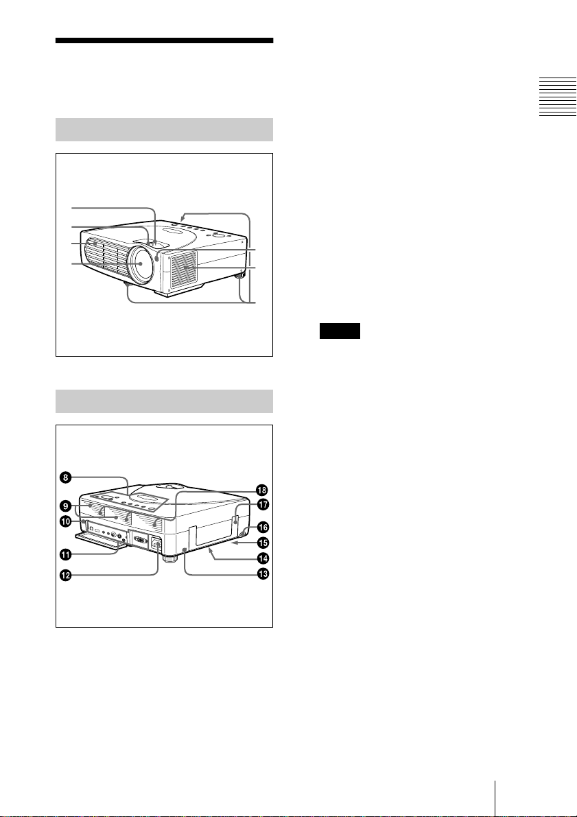
Location and
1 Zoom ring
Adjusts the picture size.
Function of Co ntrols
Front/Left Side
1
2
3
4
Rear/Rig h t Side /B o ttom
7
6
5
2 Focus ring
Adjusts the picture focus.
3 Ventilation holes (exhaust)
4 Lens
5 Adjuster
When a picture is projected on the
exterior of the s creen, adjust the picture
using this adjuster.
For details on how to use the adjusters,
see “How to use the adjuster” on page
10.
6 Ventilation holes (intake)/air
filter cover
Notes
• Do not place a n ythin g ne a r the
ventilat ion hole s as it m ay ca use inte rnal
heat build-up.
• Do not place your hand or objects near
the ventilation holes as i t may cause the
air coming out heat build-up.
• To ma intain optim al per form ance, clean
the air filter every 300 h ou rs .
7 Front remote control detector
(SIRCS receiver)
Overview
8 Contro l pane l
For details, see “Control Panel” on
page 11.
9 Speakers
q;
q; Rear remote control detector
q;q;
(SIRCS receiver)
qa
qa Conn ec tor pa n el
qaqa
For details, see “Connector Panel” on
page 12.
qs
qs AC IN socket
qsqs
Connects the supplied AC power cord.
Location and Function of Controls
GB
9
qd
qd Security lock
qdqd
Connects to an optional security cable
(Kensington’s).
The security lock corresponds to
Kensington’s MicroSaver
System.
If you require further information,
contact
Kensington
2855 Campus Drive
San Mateo, CA 94403
In North America
Phone: 800-235-6708
Fax: 800-247-1317
Outside North America
Phone: 847-541-9500
Home page address:
http://www.kensington.com/
qf
qf Ventillation h o le s ( int ake,
qfqf
®
Security
bottom)
qg
qg Lamp cover (bottom)
qgqg
qh
qh RELEASE (adjuster adjustment)
qhqh
button
For details, see “How to use the
adjuster” on page 10.
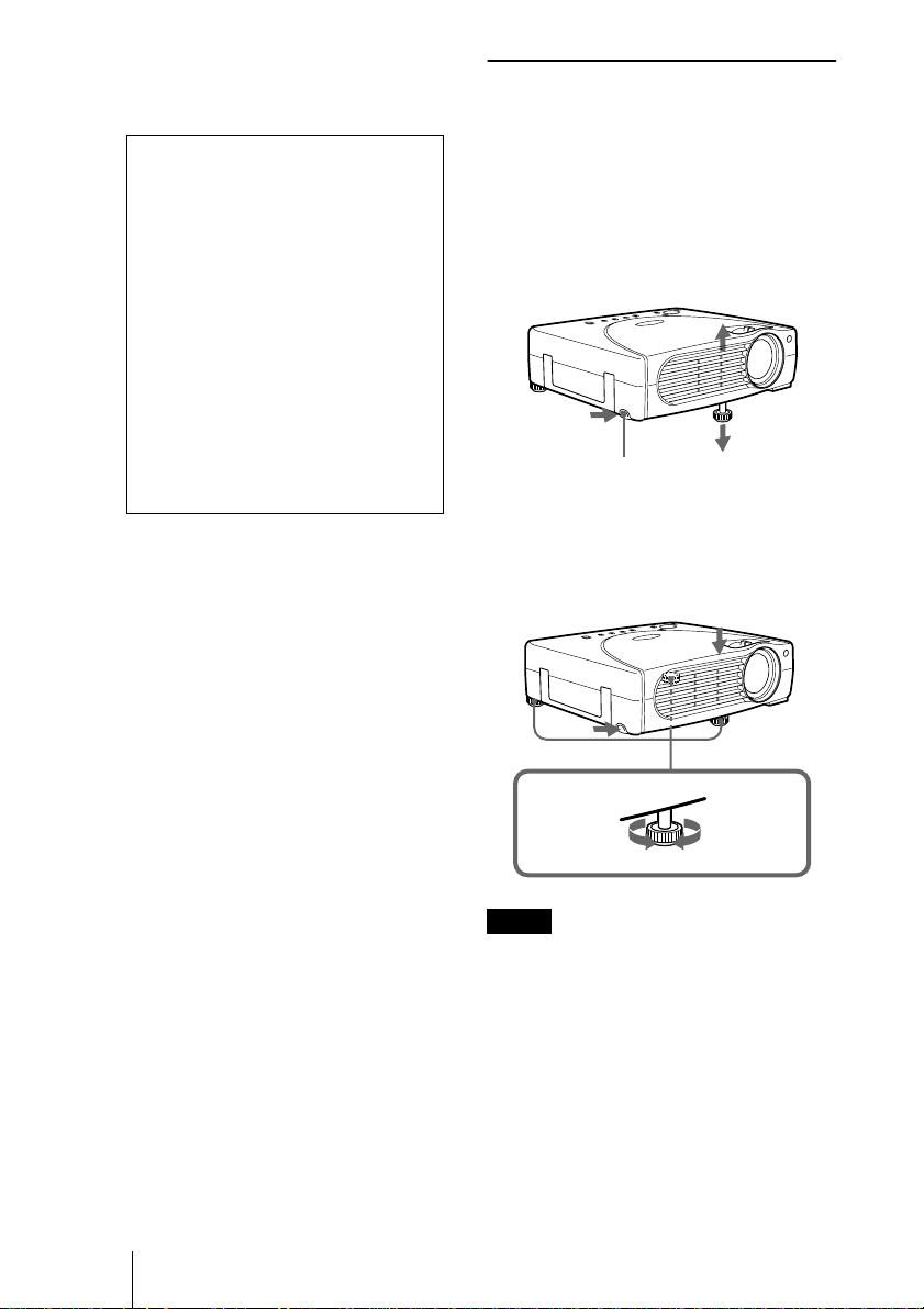
How to use the adjuster
To adjust the height
Adjust the height of the projecto r as follows:
1
Lift the projector and press the
RELEASE bu tton.
The adjuster will extend from the
projector.
RELEASE button
2
While pr essing the button, lowe r the
projector. Then, release the button.
For fine adjustment, turn the adjusters to
the right and the left.
qj
qj Carrying handle
qjqj
Pull up the ha ndle fr om t he proj ector for
carrying.
qk
qk Ventilation holes (intake, rear)
qkqk
GB
Location and Function of Controls
10
to lower the
projector
Notes
• Do not rem ove the adjusters from the
projector. Do not use the pr ojec tor with the
adjusters remo ved.
• Be caref u l not to let the projector d own on
your fingers.
• Do not push hard on the top of the projector
with the a djusters out.
to ra ise th e
projector
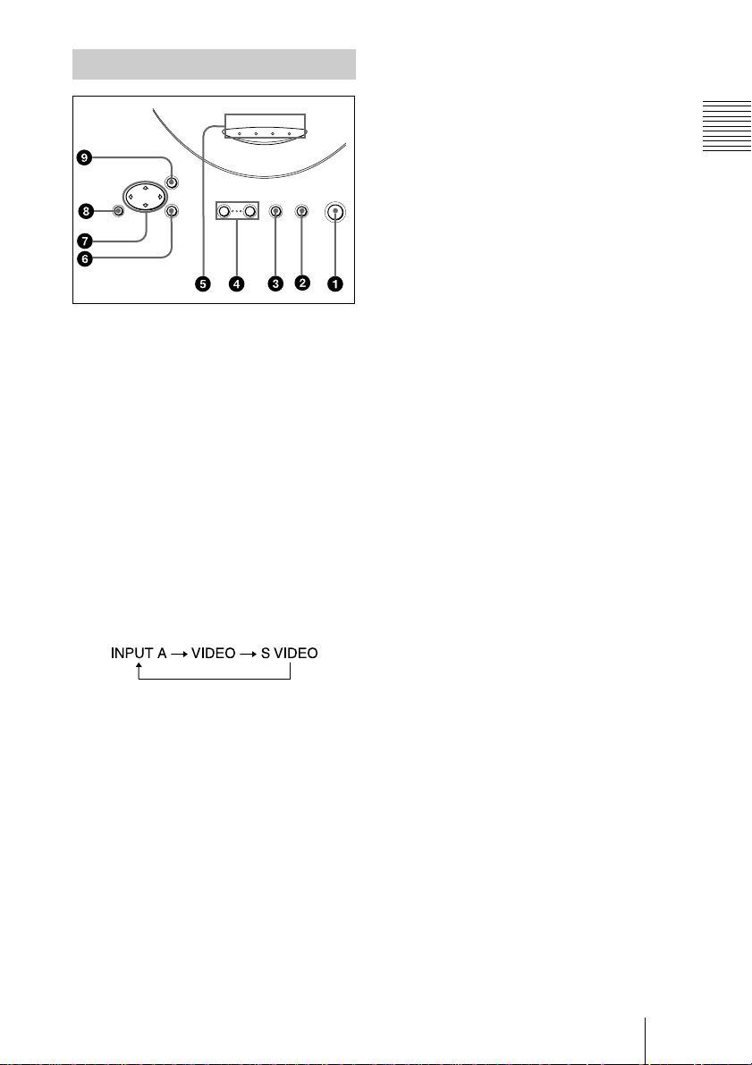
Control Panel
FAN/
POWER
LAMP/
COVER
MENU
RESET ENTER
– VOLUME +
1 I / 1111 (ON/STANDBY) key
Turns on and off the projector when the
projector is in standby mode. The ON/
STANDBY indicator lights in green
when the power is turned on.
When turning off the power, press
the I / 1 key t wice following th e
message on the screen, or press and hold
the key for about one second.
For details on steps for turning off the
power, see “To turn off the power” on
page 24.
2 INPUT key
Selects the input signal. Each time you
press the key, the input signal switches
as follows:
3 APA (Auto Pixel Alignment) key
Adjusts a picture clearest automati cally
while a signal is input from a computer.
4 VOLUM E +/– keys
Adjust the volume of the built-in
speakers.
+ : Increases the volume.
– :
Decreases the volume.
ON/
TEMP
SAVING
STANDBY
APA INPUT ON/STANDBY
I / 1
5 Indicators
• LAMP/COVER: Lights up or flashes
under the following condition s:
– Lights up when the lamp has
reached the end of its life or
becomes a high temperature.
– Flashes when th e la mp cover or air
filter cover is not secured firmly.
• FAN/TEMP (Temperature): Lights
up or flashes under the following
conditions:
– Lights up when temperature inside
the projector becomes unusually
high.
– Flashes when the fan is broken.
• POWER SAVING: Lights up wh en
the projector is in power saving mode.
When POWER SAVING in the SET
SETTING menu is set to ON, the
projector goes in to power saving mod e
if no signal is input for 10 minutes.
Although the lamp goes out, the
cooling fan keeps run ning. In power
saving mode, any ke y does not
function for the first 30 seconds. The
power saving mode is canceled when a
signal is input or any key is pressed.
• ON/STANDBY: Lights up or flashes
under the following condition s:
– Lights in red when a AC power cord
is plugged into a wall outlet. On ce in
standby mode, you can turn on the
projector with the I / 1 key.
– Lights in green when the power is
turned on.
– Flashes in green while the cooling
fan runs after the power is turned off
with the I / 1 key. The fan runs for
about 60 seconds after the power is
turned off.
The ON/STANDBY indicator
flashes quickly for the first 30
seconds. During this time, you
cannot light up the ON/STANDBY
indicator with the I / 1 key.
For details on the LAMP/COVER and
the FAN/TEMP indicators, see page 35.
Overview
6 ENTER key
Enters the settings of items in the menu
system.
Location and Function of Controls
11
GB
7 Arrow keys (MMMM/mmmm/<<<</,,,,)
Select the menu or to make various
adjustments.
8 RESET key
Resets the value of an item back to its
factory preset value. This key functions
when the menu or a setting item is
displayed on the screen.
9 MENU key
Displays the on-screen menu. Press
again to clear the menu.
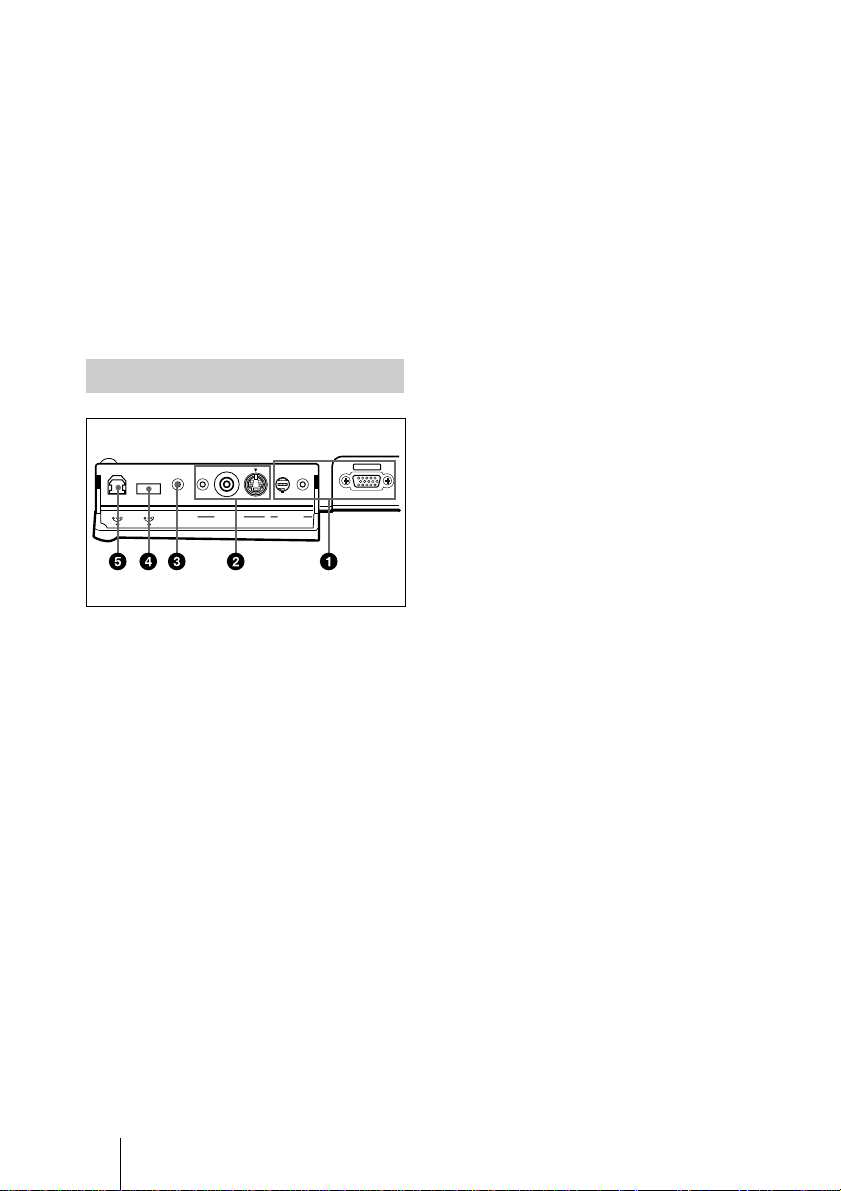
Connector Panel
Rear side
CONTROL S
VIDEO IN INPUT A
IN / PLUG IN
POWER
1 INPUT A connector
Connect to external equipment such as a
computer.
• INPUT A connector (HD D-sub 15pin, female): Connects to the monito r
output on a computer using the
supplied cable.
When inputting a co mponent or 15k
RGB signal, use an optional cable.
For details, see “To connect a 15k RGB/
Component equi pme nt” on page 19.
• AUDIO (stereo minijack)
connector: Connects to the audio
output of the computer.
• MOUSE connector (6-pin):
Connects to the PS/2 mouse port on a
computer via the supplied mouse
cable, to control the mouse function of
the connected comput er.
INPUT A
2 VIDEO IN connector
Connect to external video equipment
such as a VCR.
• S VIDEO (mini DIN 4-pin):
Connects to the S video output (Y/C
video output) of video equipment.
• VIDEO (phono type): Connects to
the composite vi deo output of video
equipment.
• AUDIO (stereo minijack)
connector: Connects to the audi o
output of the VCR.
3 CONTRO L S IN/PLUG IN
POWER (DC 5V output) jack
Connects to the control S out jack of the
Sony equipmen t.
Connects to the CONTROL S OUT jack
on the supplied Remote Commander
when using it as a wired Remote
Commander. In this case, you do not
need to install the batteries in the
Remote Commander, since the power is
supplied from this jack.
4 USB connector (USB A-plug for
downstream, 4-pin)
Connect to USB equipment such as a
mouse, camera, etc.
5 USB connector (USB B-plug for
upstream, 4-pin)
Connect to the USB connector on a
computer.
When you connect the pro jector to the
computer, the projector recognizes the
mouse of the computer connected to the
INPUT A connector and you can control
the mouse function with the supplied
Remote Commander. The supplied
application software can be installed in
the comput er at tach e d t o t his co nne ct or.
GB
Location and Function of Controls
12
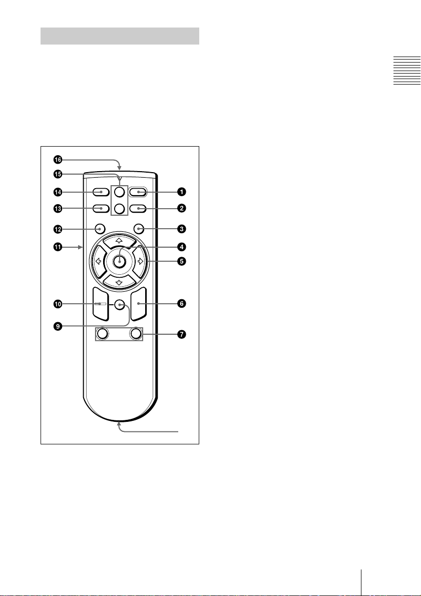
Remote Commander
8
The keys that have the same names as those
on the control panel function identically.
You can control a connected computer using
the Remote Commander.
For details, see “To control the computer
using the supplied Re mot e Comm ander ” on
page 23.
+
VOLUME
–
RESET
(D ZOOM)
FUNCTION
I / 1
APA
R
CLICK
MUTING
PIC
INPUT
MENU ENTER
+
–
D ZOOM
12
6 R CLICK key
Functions as the right button on a mouse.
7 FUNCTION 1, 2 keys
These keys function when the supplied
application software is used.
When you connect the projector with a
computer, you can open a file on the
screen by just pressing the FUNCTION
key. This will enhance your
presentation. To use this function,
allocate a file to the FUNCTION key by
using the application software.
For details, see the README file and
the HELP file supplied with the
application software.
8 CONTROL S OUT jack (stereo
minijack)
Connects to the CONTROL S IN jack on
the projector with the connecting cable
(not supplied) when using the Remote
Commander as a wired one. In this case,
you do not need to install the batteries as
the power is supplied via the CONTROL
S IN jack on the projector.
9 RESET (D ZO O M ) key
Resets the value of an item back to its
factory preset value or returns the
enlarged image back to its original size.
Overview
1 I / 1111 key
2 APA (Auto Pixel Alignment) key
3 ENTER key
4 Joystick
Functions as the mouse of the computer
connected to the unit.
5 Arrow (
M/m/</,
) keys
0 D ZOOM +/–
key
Enlarges the image at a desired location
on the screen.
+: Pressing the + key on ce highlights
one of the images divi ded into 16.
Use an arrow key (M/m/</,) to
move the highlight portio n to the
point in the image to be enlarge d.
Press the + key repeatedly until the
image is enlarged to your
requirements.
–: Pressing the – key reduces an image
that has been enlarged with the D
ZOOM + key.
qa L CLICK key
Functions as the left button on a mouse.
qs MENU key
qd INPUT key
Location and Function of Controls
13
GB
qf MUTING PIC key
Cut off the picture. Press again to restore
the picture.
qg VOLUME +/– keys
qh Infrared transmitter
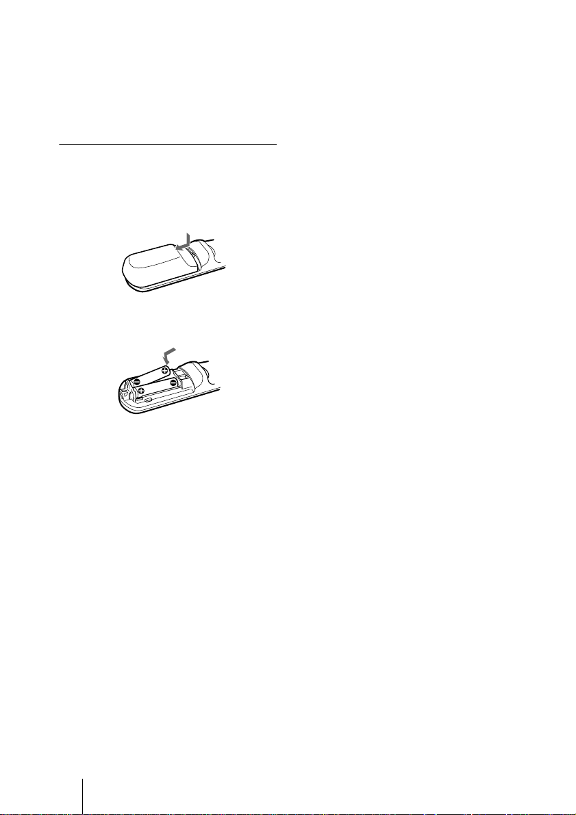
To insta ll b a tt e rie s
1
Push and slide to open the lid, then
install the two size AA (R6) batteries
(supplied) with the co rr e c t polarity.
Be sure to install the
battery from the
side.
#
Notes on batteries
• Make sure that the battery orientation is
correct when inserting batteries.
• Do not mix an old batt ery with a new one
or different types of batteries.
• If you do not use the Rem ote C omm ande r
for a long time, remove the batteries to
avoid damage from battery leakage. If
batteries have leaked, remo ve them, wipe
and dry the battery co mpartment, and
replace the batteries with new ones.
Notes on Remote Commander
operation
• Make sure that nothing obstructs the
infrared beam between the Remote
Commander and the remote control
detector on the projector . Direct the
Remote Commander toward the front or
rear remote control detector.
• The operation range is limited. The shor ter
the distance between the Remote
Commander and the projector is, the wider
the angle within which the commander ca n
control the projector becomes.
2
Replace the lid.
GB
14
Location and Function of Controls
Setting Up and Projecting
B
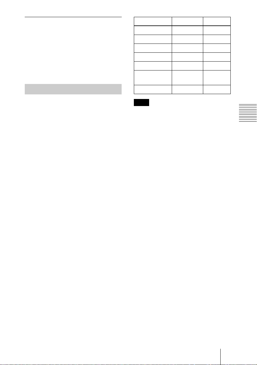
Installing the Projector
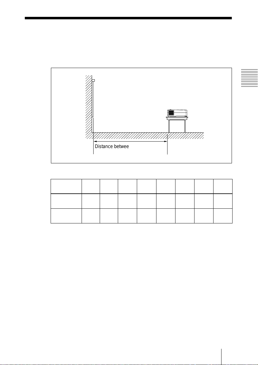
This section describes h ow to install th e p r o jec tor.
The distance between the lens and the screen varies depending on the size of
the screen. Use the following table as a guide.
Distance between the screen and
the center of the lens
Unit: m (feet)
Screen size
(inches)
Minimum
Distance
Maximum
Distance
40 60 80 100 120 150 200 300
1.5
(4.8)
1.8
(5.8)
2.2
(7.3)
2.7
(8.8)
3.0
(9.8)
3.6
(11.8)
3.8
(12.4)
4.5
(14.8)
4.5
(14.9)
5.4
(17.8)
5.7
(18.6)
6.8
(22.3)
7.6
(24.9)
9.1
(29.8)
11.4
(37.5)
13.7
(44.9)
Setting Up and Projecting
For deta ils, see “Installation Example” o n pag e36.
For deta ils on ceiling in sta lla tio n, consult w ith qualified Sony person ne l (fee
charged).
Installing the Projector
15
GB

Connecting the Projector
When making connections, be sure to do the following:
• Turn off all equipment before making any connections.
• Use the proper cables for each connection.
• Insert the cable plugs properly; plu g s that are not f ully in se r te d often
generate no ise. Whe n pulling o ut a cable, b e sure to p ull it out from the plug,
not the cable itself.
Connecting with a Computer
This section describes how to connect the projector to a computer.
For more information, refer to the computer’s instruction manu a l.
Notes
• The projector accepts VGA, SVGA, XGA, and SXGA signals. However, we
recommend that you set the output mode of your computer to SVGA (VPL-CS10) or
XGA ( VPL-C X10) mode fo r the exte r n al moni tor.
• If you set your computer, such as a notebook type, to output the signal to both your
computer’s display and the external monitor, the picture of the external monitor may
not app ear prop erly. Se t your co mputer t o output the signa l to only th e extern al
monito r.
For de tails, refer to the operating in structions supplied with your computer.
• Supplied mouse cable may not work properly according to your computer.
• This pr o j e ctor is compatible with a DDC2B (Digital D ata Channel 2 B ). If your
compu ter i s co m pat ible w ith a D DC , tu rn t he p ro jecto r on a ccor din g to the foll ow ing
procedures.
1 Connect the projector to the comp uter by using the supplied H D D-sub 1 5 pin cable.
2 Turn the projector on.
3 Start the computer.
GB
Connecting the Projector
16
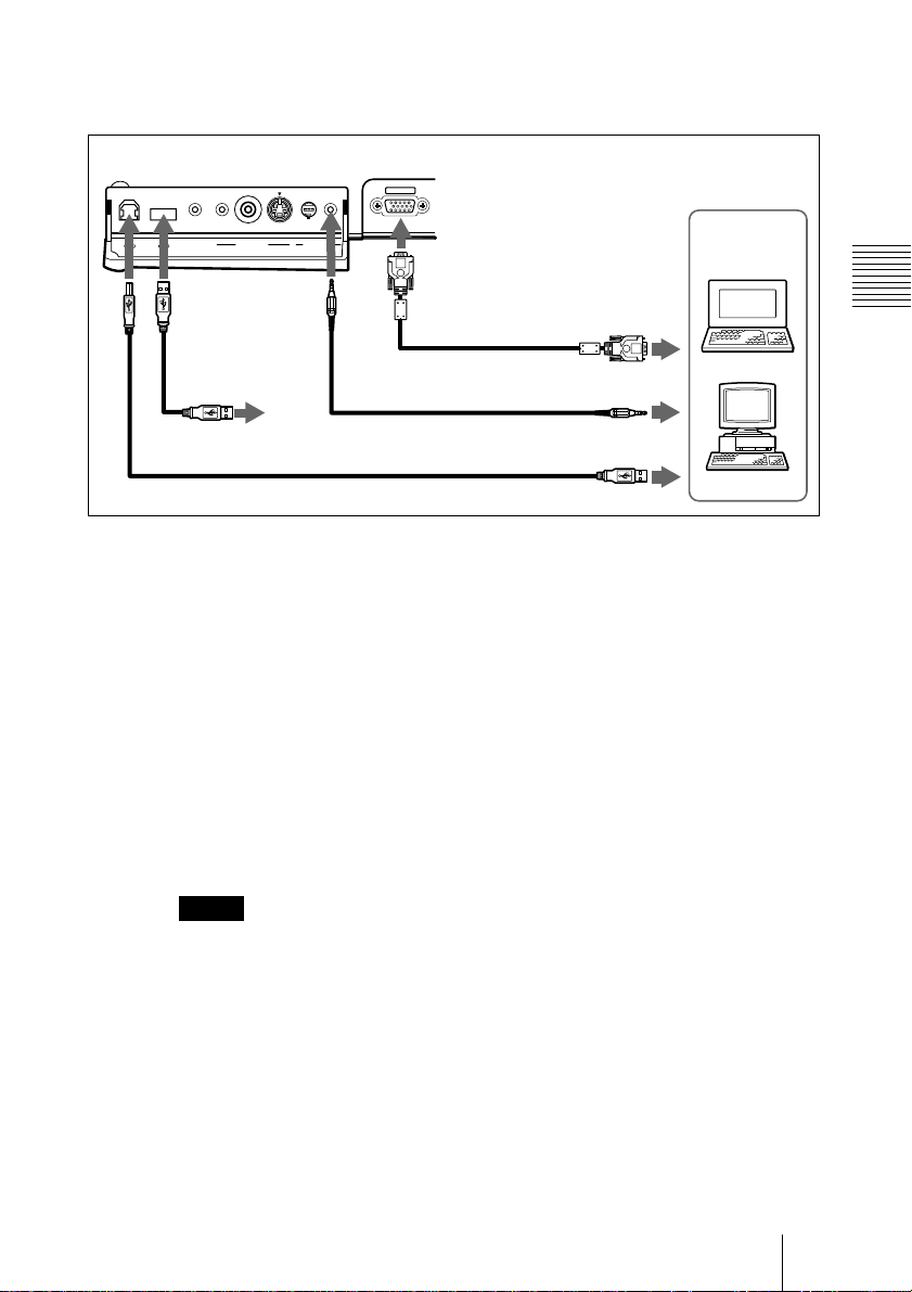
To connect an IBM PC/AT compatible computer
When you use a USB mouse and USB equipment
Rear side
INPUT A
CONTROL S
VIDEO IN INPUT A
IN / PLUG IN
POWER
to USB equipment
USB cable A type – B type (supplied)
On the USB function
When connecting the projector to a computer by using the USB cable for the
first time, the c omputer r ec ognizes the f ollowing d evices automatically.
1 USB hub (general use)
2 USB human interface device (wireless mouse function)
3 USB human interface device (projector control function)
The computer also recognizes the device connected to the downstream
connector on the projector.
Recommended operating environment
When y ou use the U S B fun c tion , conn e ct you r com p ute r as illu strate d a bo ve.
This application software and the USB function can be used on a co m puter
loaded with Windows 98, Windows 98 SE or Windows 2000 preinstall
models.
HD D-sub
15-pin cable
(supplied)
Stereo audio connecting
cable (not supplied)
to monitor output
to audio output
to USB connector
Computer
Setting Up and Projecting
Notes
• As the projector recognizes the USB mouse when the computer is
connected to the USB connector, do not connect anything to the PS/2
mouse port.
• Your computer may not start correctly when connected to the projector
via the USB cable. In this case, disconnect the USB cable, restart the
computer, then connect the computer to the projector using the USB
cable.
• This projector is not guaranteed for suspend, standby mode. When you
use the projector in suspend, standby mode, disconnect the projector
from the USB port on the computer.
• Operations are not guaranteed for all the recommended computer
environments.
Connecting the Projector
17
GB
Rear side
When you use a PS/2 mouse port
INPUT A
CONTROL S
VIDEO IN INPUT A
IN / PLUG IN
POWER
HD D-sub
15-pin cable
(supplied)
Stereo audio connecting cable
(not supplied)
PS/2 Mouse cable
(supplied)
to monitor output
to audio output
to mouse port
(PS/2)
To connect a Macintosh computer
Use an ADP-20 signal adapter (not supplied). In this case, however, you can
not control the mouse of the computer by the Remote C ommander.
Connecting with a VCR or 15k RGB/Component Equipment
This section describes how to connect the projector to a VCR and 15k R GB/
component equipment.
For more in f or mation, refer to the instruction manuals of th e e quipment y o u
are connecting.
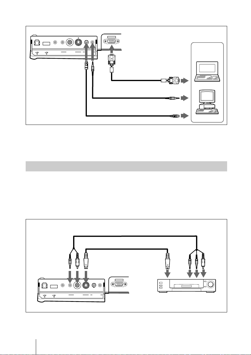
To connect a VCR
Computer
GB
Rear side
CONTROL S
IN / PLUG IN
POWER
Connecting the Projector
18
VIDEO IN INPUT A
AV cable (supplied)
S-Video cable (not supplied)
to S video
INPUT A
output
audio
output
(R/L)
to
to video
output
VCR

To connect a 15k RGB/Component equipment
Stereo audio connecting cable (not supplied)
SMF-402 Signal Cable (not supplied)
HD D-sub 15-pin (male) ↔ 3 × phono jack
Rear side
to RGB/
component
output
INPUT A
CONTROL S
VIDEO IN INPUT A
IN / PLUG IN
POWER
15k RGB/Componen t equipment
Notes
et the aspect ratio using ASPECT in the INPUT SETTING menu
• S
according to the input signal.
you connect the unit to 15k RGB/component video equipment,
• When
select RGB or component with the INPUT-A setting in the SET
SETTING menu.
se the composite sync signal when you input the external sync signal
• U
from 15k RGB/component equipment.
to audio
output
Setting Up and Projecting
Connecting the Projector
19
GB
Selecting the Menu Language
You can select one of seven languages for displaying the menu and other onscreen displays. The factory setting is English.
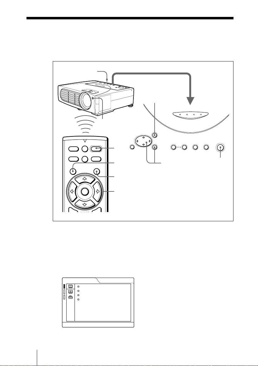
1
3
LAMP/
COVER
Front remote control
detector
MENU
FAN/
POWER
ON/
TEMP
SAVING
STANDBY
APA INPUT ON/STANDBY
+
VOLUME
–
I / 1
APA
MUTING
PIC
INPUT
MENU ENTER
RESET ENTER
2
3
– VOLUME +
4,5,6
4,5,6
4,5,6
RESET
+
1
Plug the A C p ow er c ord o n the rear side on the p rojec tor into a w all ou tlet.
2
Press the I / 1 key to turn on the projector.
3
Press the MENU key.
The menu appears.
The menu presently selected is shown as a yellow button.
PICTURE CTRL
R
CLICK
CONTRAST:
BRIGHT:
GAMMA MODE: GRAPHICS
COLOR TEMP: HIGH
80
50
INPUT-A
I / 1
2
GB
Selecting the Menu Language
20
4
Press the M or m key to sele ct the S ET S ET TING m enu, th en pre ss the ,
or ENTER key.
The selected menu appears.
SET SETTING
STATUS: ON
INPUT-A: RGB
KEYSTONE MEMORY:
DIGITAL KEYSTONE:
LANGUAGE: ENGLISH
INSTALLATION:
POWER SAVING
SIRCS RECEIVER:
LAMP TIMER:
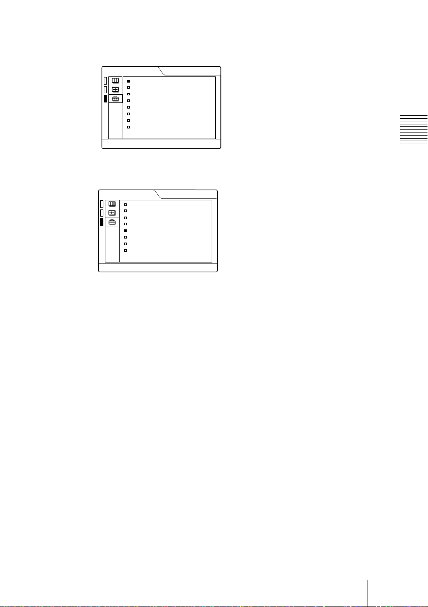
5
Press the M or m key to select “LANGUAGE,” then press the , or
ON
OFF
FLR-FRONT
: OFF
FRONT&REAR
00010h
INPUT-A
ENTER key.
SET SETTING
STATUS: ON
INPUT-A: RGB
KEYSTONE MEMORY:
DIGITAL KEYSTONE:
LANGUAGE: ENGLISH
INSTALLATION:
POWER SAVING
SIRCS RECEIVER:
LAMP TIMER:
6
Press the M or m key to select a language, then press the < or ENTER
ON
OFF
FLR-FRONT
: OFF
FRONT&REAR
00010h
INPUT-A
key.
The menu changes to the selected language.
Setting Up and Projecting
To clear the menu
Press the M E NU key.
The me n u disappear s a utomatically if a ke y is not presse d fo r o ne minute.
Selecting the Menu Language
21
GB
Projecting
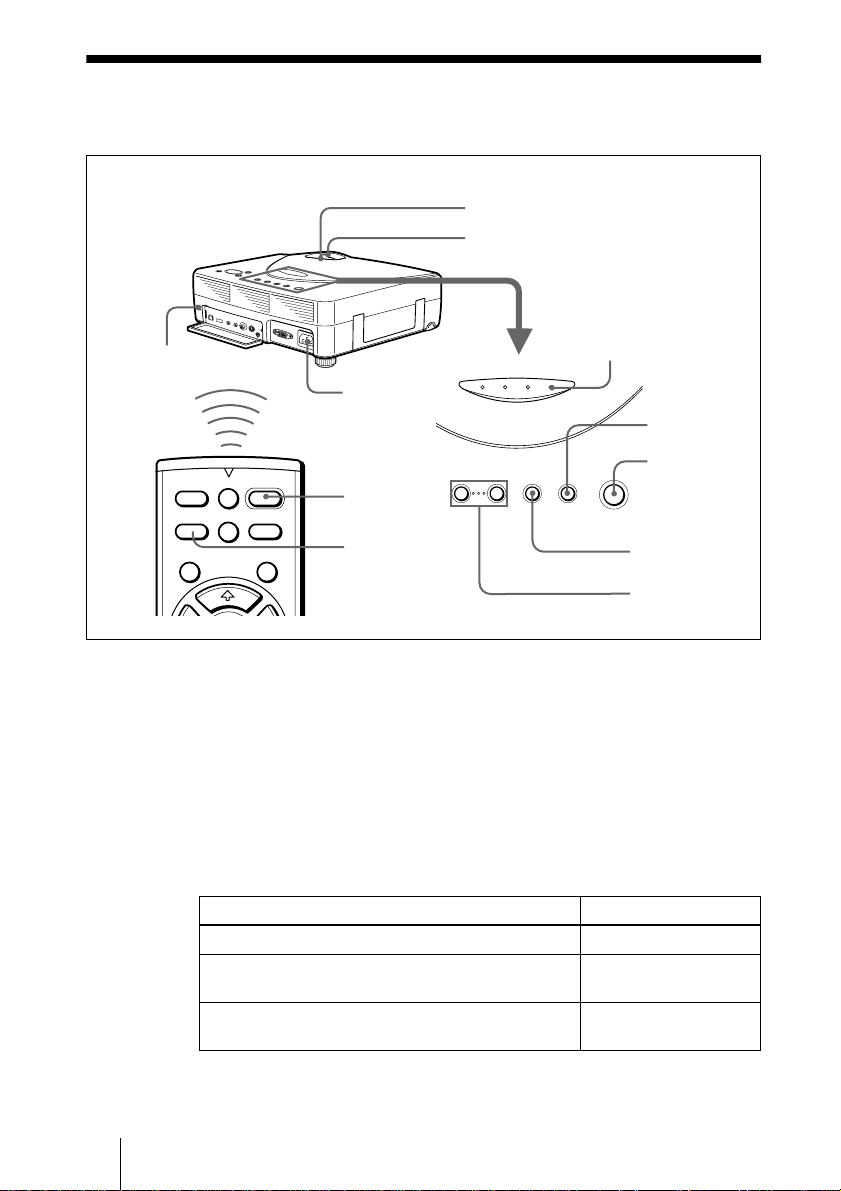
5
6
Rear re mote control
detector
LAMP/
COVER
FAN/
TEMP
ON/ST AN D BY indicator
POWER
ON/
SAVING
STANDBY
1
MENU
RESET
MUTING
PIC
INPUT
MENU ENTER
1
I / 1
+
VOLUME
APA
–
Plug the A C pow er cord on th e rear s ide on the p rojector into a w all ou tlet,
ENTER
2
4
– VOLUME +
then connect all equipment.
The ON/STANDBY indicator lights in red and the projector goes into
standby mode.
2
Press the I / 1 key.
The ON/STANDBY indicator lights in green.
3
Turn on the equipment connected to the projector.
4
Press the INPUT key to select the input source.
To input from Press INPUT to display
Computer connected to the INPUT A connector INPUT A
Video equipment connected to the VIDEO input
connector
Video equipment connected to the S VIDEO input
connector
APA INPUT ON/STANDBY
I / 1
APA key
VOLUME +/–
keys
VIDEO
S VIDEO
4
2
GB
22
Projecting
5
Turn the zoom ring to adjust the size of the picture.
6
Turn the f o c us ring to adju st the focus.
Caution
Looking into the lens when projecting may cause injury to your eyes.
To adjust the volume
Press VOLU M E +/– keys. The volume can b e adjusted for each of IN PUT A ,
VIDEO and S VIDEO input.
To cutoff the picture
Press the MUTING PIC key on the Remote Commander.
To restore the picture, press the MUTING PIC key again.
To control the computer using the supplied Remote Commander
When you connect an IBM PC/AT com patible to the projector, you can control
the mouse of the computer using the Rem ote Commander.
The R/L CLICK k e y s and joystic k fu n c tio n as follow s.
Key and jo ys tic k Functio n
R CLICK (front) Right button
L CLICK (rear) Left button
Joystick Corresponds with the movements of the mouse
Note
Make sur e th a t no th ing ob s tru cts th e in fra red be am betwe e n th e R e m ot e C o m mander
and the remote control detector on the projector.
Setting Up and Projecting
To get the clearest picture
You ca n a d ju s t picture quality when pr o je cting a sign al from the computer .
1
Project a s till p ic ture from the compu te r .
2
Press the APA key.
“Com plete!” appears on the screen when the picture is adjusted properly.
Notes
• Press the APA key when the full image is displayed on the screen. If there are black
edges a r ound th e i mage, the APA funct ion will not func tion prop e r ly and the imag e
may extend beyond the screen.
• When you switch the input signal or re-connect a computer, press the APA key again
to adjust the picture again.
• You can cancel the adjustment by pressing the APA key again while “ADJUSTING”
appears on the screen.
• The picture may not be adjusted properly depending on the kinds of input signals.
• Adjus t the item s in the I NPUT SETT ING menu when you adju st the pi cture m anuall y.
Projecting
23
GB

To turn off the p ower
1
Press the I / 1 key.
“POWER OFF? Ple ase press I / 1 key again.” appears to conf irm that you
want to turn off the power.
Note
A message disappears if you press any key except the I / 1 ke y, or if you d o no t
press any key for five seconds.
2
Press the I / 1 key again.
The ON/STANDBY indicator flashes in green and the fan continues to run for
about 60 seconds to reduce the internal heat. Also, the ON/STANDBY
indicator flashe s quickl y for the first 30 seconds . During this tim e, you will not
be able to light up the ON/STANDBY indicator with the I / 1 key.
3
Unplug th e AC pow er cor d from th e w all outlet afte r the fan stops run ning
and the ON/STA NDBY in dicator lights in re d.
When you cannot confirm the on-screen message
When you cannot confirm the on-screen message in a certain condition, you can
turn off the power by holding the I / 1 key for abo ut one second.
Note
Do not un pl ug th e A C p o w er co rd w h ile the f an is still r un n in g; oth e rw is e, th e f an w ill
stop even though the internal heat is still high, which could result in a breakdown of the
projector.
GB
24
On air filter
To main tain optima l p e r formance, clean the air filter every 300 hours.
Projecting
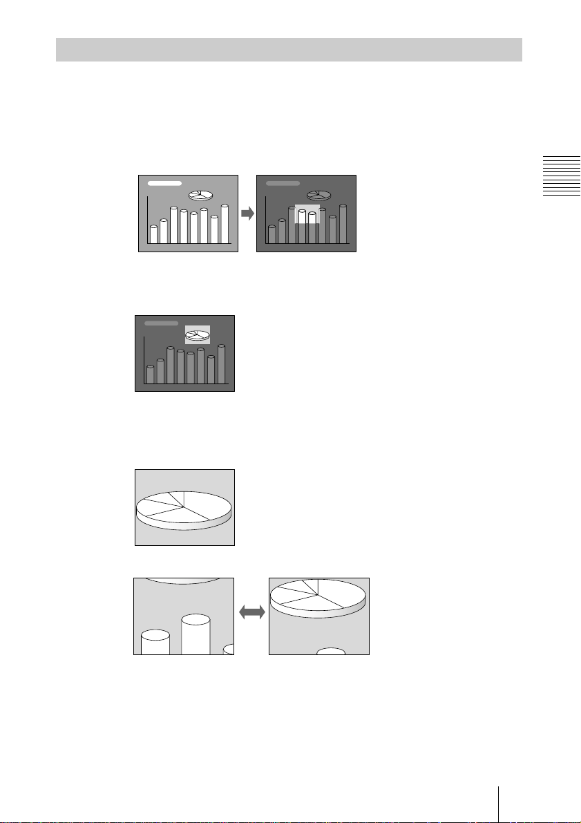
Effective Tools for Your Presentation
To enlarge the image (Digital Zoom function)
You can select a point in the image to enlarge.
1
Project the original size picture and press the D ZOOM + key on the
Remote Commander.
One of images divided into 16 is highlighted at the center of the image.
2
Move th e highlight po rtion to the poin t you want to enlarge by pre ssing the
arrow keys (M/m/</,).
3
Press the D ZOOM + key again.
The highlight portion displayed in step 2 is enlarged. By pressing the + key
repeatedly, the image size increases. (ratio of enlargement: max. 4 times)
Setting Up and Projecting
Use the arrow keys (
To return the image back to its original size
Press the D ZOOM – key on the Remote Commander. Just pressing the
RESE T (ZOOM) key retu rns the imag e b ack to its original size immediately.
M/m/</,
) to scroll the enlarged image.
Projecting
25
GB
Adjustments and Settings Using the Menu
B
• When changing the adjust ment level:
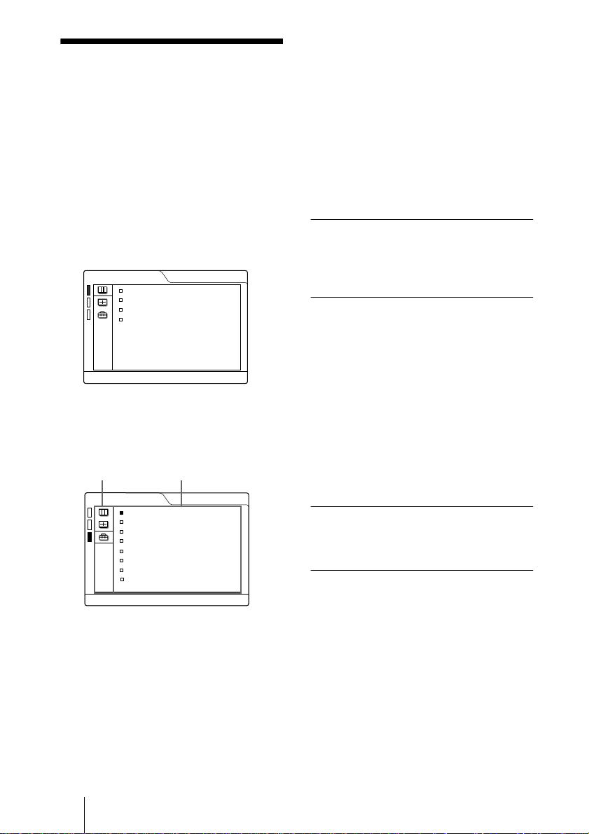
Using the MENU
To increase the number, press the
, key.
To decrease the number, press the m
The projector is equipped with an on-screen
menu for making various adjustments and
settings. You can change the menu language
displayed in the on-screen menu.
To change the menu langu age, see
“Selecting the Menu Language” on page 20.
1
Press the MENU key.
The menu appears.
The menu presently selected is shown as
a yellow button.
PICTURE CTRL
CONTRAST:
BRIGHT:
GAMMA MODE: GRAPHICS
COLOR TEMP: HIGH
INPUT-A
80
50
or < key.
Press the ENTER key to restore the
original screen.
• When changing the setti ng:
Press the M or m key to change the
setting.
Press the ENTER or < key to restore
the original screen.
To clear the menu
Press the MENU key.
The menu disappears automatically if a key
is not pressed for one mi nute.
To reset items that have been
adjusted
Press the RESET key.
“Complete!” appears on the screen and the
settings appearing on the screen are reset to
their factory preset values.
Items that can be reset are:
2
Use the M or m key to select a menu,
then press the , or ENTER key.
The selected menu appears.
Menus
Setting items
•“CONTRAST,” “BRIGHT,” “COLOR,”
“HUE,” and “SHARP” in the PICTURE
CTRL menu
•“DOT PHASE,” “SIZE,” and “SHIFT” in
the INPUT SETTING menu
•“DIGITAL KEYSTONE” in the SET
SETTING menu
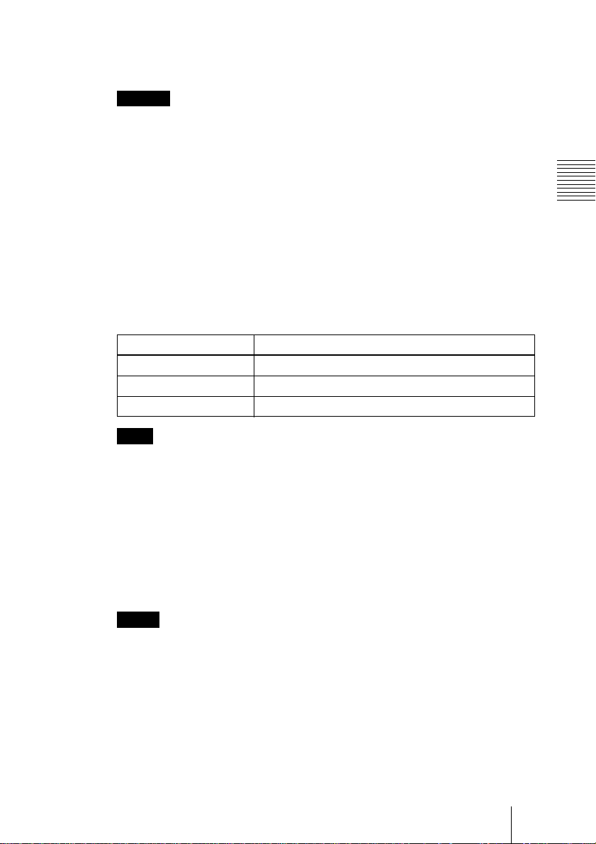
SET SETTING
STATUS: ON
INPUT-A: RGB
KEYSTONE MEMORY:
DIGITAL KEYSTONE:
LANGUAGE: ENGLISH
INSTALLATION:
POWER SAVING
SIRCS RECEIVER:
LAMP TIMER: 000
ON
OFF
FLR-FRONT
: OFF
FRONT&REAR
INPUT-A
About the memory of the settings
The settings are automatically stored in the
projector memory.
10h
If no sign a l is input
If there is no input signal, “NO INPUT–
Cannot adjust this item.” appears on the
screen.
3
Select an item .
Use the M or m key to select the item ,
then press the , or ENTER key.
or
M
4
Make the setting or a d justment o n a n
item.
GB
Using the MENU
26
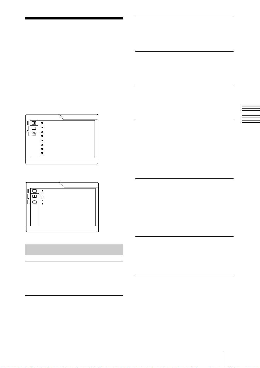
The PICTURE CTRL Menu
COLOR
Adjusts color intensity. The higher the
setting, the greater the intensity. The lower
the setting, the lower the intensity.
The PICTURE CTRL (control) menu is used
for adjusting the picture.
Items that cannot be adjusted depending on
the input signal are not displayed in the
menu.
For details on th e unadjustable items, see
page 42.
When the video signal is input
PICTURE CTRL
CONTRAST:
BRIGHT:
COLOR:
HUE:
SHARP:
D. PICTURE:
COLOR TEMP:
COLOR SYS:
80
50
50
50
50
OFF
LOW
AUTO
VIDEO
When the RGB signal is input
PICTURE CTRL
CONTRAST:
BRIGHT:
GAMMA MODE: GRAPHICS
COLOR TEMP: HIGH
INPUT-A
80
50
HUE
Adjusts color tones. The higher the setting,
the picture becomes greenish. The lower the
setting, the picture becomes purplish.
SHARP
Adjusts the picture sharpness. The higher the
setting, the sharper the picture. The lower
the setting, the softer the picture.
D. (Dynamic) PICTURE
Emphasizes the black color.
ON: Emphasizes the black color to produce
a bolder “dynamic” picture.
OFF: Reproduces the dark portions of the
picture accurately, in acc ordance with
the source signal.
GAMMA MODE
Selects a gamma correction curve.
GRAPHICS: Improves the reproduction of
halftones. Photos can be reproduced in
natural to nes.
TEXT: Contrasts black and white. Suitable
for images that contain lots of tex t.
Adjustments and Settings Using the Menu
Menu Items
CONTRAST
Adjusts the picture contrast. Th e hi gher the
setting, the greater the contrast. The lo wer
the setting, the lower the contrast.
BRIGHT
Adjusts the picture brightness. The higher
the setting, the brighter the picture. The
lower the setting, the darker the picture.
COLOR TEMP
Adjusts the color temperature.
HIGH: Makes the white color bluish.
LOW: Makes the white color reddish.
COLOR SYS (System)
Selects the color system of the input signal.
• AUTO: NTSC
NTSC
• PAL-M/N: PAL-M/PAL-N and NTSC
(switched automatically)
Normally, set to AUTO. If the picture is
distorted or colorless, select the color system
according to the input signal.
3.58
4.43
, PAL, SECAM and
(switched automatically)
The PICTURE CTRL Menu
3.58
27
GB
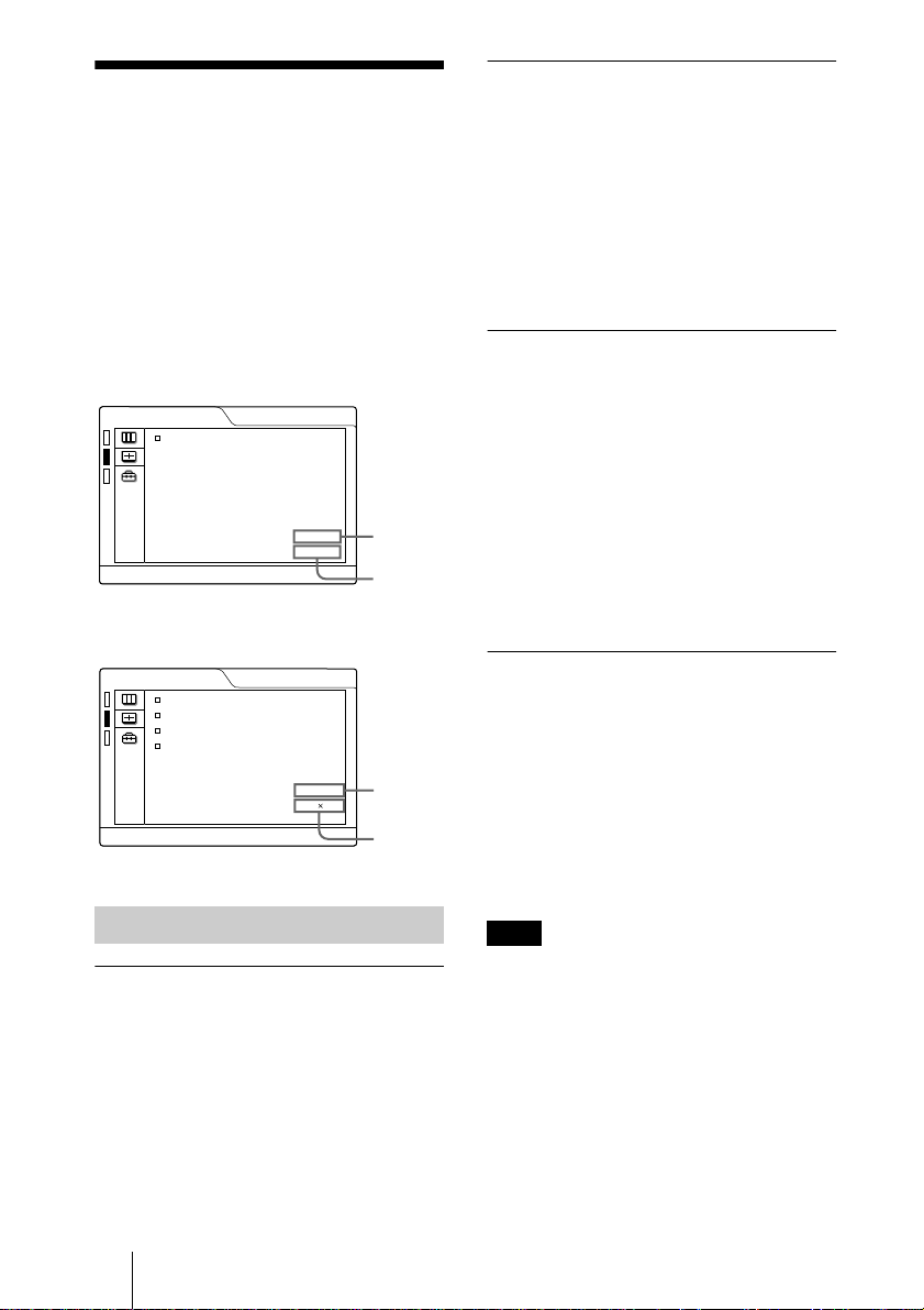
The INPUT SETTING Menu
The INPUT SETTING menu is used to
adjust the input signal.
Items that cannot be ad justed depending on
the input signal are not displayed in the
menu.
For details on the unadjustable items, see
page 42.
When the video signal is input
INPUT SETTING
ASPECT:
4:3
When the RG B signa l is in p ut
INPUT SETTING
DOT PHASE:
SIZE H
SHIFT H
SCAN CONV: ON
15
800
H:200 V:30
MENU Items
DOT PHASE
Adjusts the dot phase of the LCD panel and
the signal input from the INPUT A
connector.
Adjust the picture further for finer picture
after the picture is adjusted by pressing the
APA key.
Adjust the picture to where it looks clearest.
VIDEO
No. 01
VIDEO/60
INPUT-A
No. 13
640 480
Memory
No.
Signal
type
Memory
No.
Signal
type
SIZE
Adjusts the horizontal size of picture input
from the INPUT A connector. The higher
the setting, the larger the horizontal size of
the picture. The lower the setting, the
smaller the horizontal size of the pict ure.
Adjust the setting according to the dots of
the input signal.
For details on the suitable value for the
preset signals, see page 43.
SHIFT
Adjusts the position of the picture input from
the INPUT A connector. H adjusts the
horizontal position of the picture.V adjusts
the vertical position of the picture. As the
setting for H increases, the pictur e moves to
the right, and as the setting decreases, the
picture moves to the left.
As the setting for V increases, the picture
moves up, and as the setting decreases, the
picture moves down. Use the < or the ,
key to adjust the hori zontal position and the
M and m key for the vertical position.
SCAN CONV (Scan converter)
Converts the signal to display the picture
according to the screen size.
ON: Displays the picture according to the
screen size. The picture will lose some
clarity.
OFF: Displays the picture while matching
one pixel of input pi cture eleme nt to that
of the LCD. The picture will be clear but
the picture size will be small er.
Note
This item will not be displayed in the following
case.
VPL-CS10: When SVGA, XGA or SXGA
signal is inp ut.
VPL-CX10: When XGA or SXGA signal is
input.
GB
The INPUT SETTING Menu
28
ASPECT
Sets the aspect ratio of the picture. When
inputting 16:9 (squeezed) signal from
equipment such as a DVD player, set to
16:9.
4:3: W hen th e pic ture with rati o 4:3 is input.
16:9: When the picture with ratio 16:9
(squeezed) is input.
About the Preset Memory No.
Signal Memory No. SIZE
Super Mac-2 23 1312
SGI-1 23 1320
Macintosh 19" 25 1328
Macintosh 21" 27 1456
Sony News 36 1708
PC-9821
1280 × 1024
WS Sunmicro 37 1664
36 1600
This projector has 37 types of preset data for
input signals for INPUT-A (the preset
memory). When a preset signal is input, the
projector automatical ly detects the signal
type and recalls the data for the signal from
the preset memory to adjust it to an optimum
picture. The memory number and signal type
of that signal are displa ye d in the INP U T
SETTING menu. You can also adjust th e
preset data through the INPUT SETTING
menu.
This projector has 20 types of user memories
for INPUT-A into which you can save the
setting of the adjusted data for an unpreset
input signal.
When an unpreset signal is input for the first
time, a memory num ber is displayed as 00.
When you adjust th e data of the signal in the
INPUT SETTING menu, it will be
registered to the projector. If more than 20
user memories are registered, the newest
memory always overwr ites the oldest one.
See the chat on page 43 to find if the signal
is registered to the preset memory.
Since the data is recalled from the preset
memory about the following signals, yo u
can use these preset data by adjustin g SIZE.
Make fine adjustment by adjusting SHIFT.
Note
When the aspect ratio of input signal is other
than 4:3, a part of the screen is displayed in
black.
Adjustments and Settings Using the Menu
The INPUT SETTING Menu
29
GB
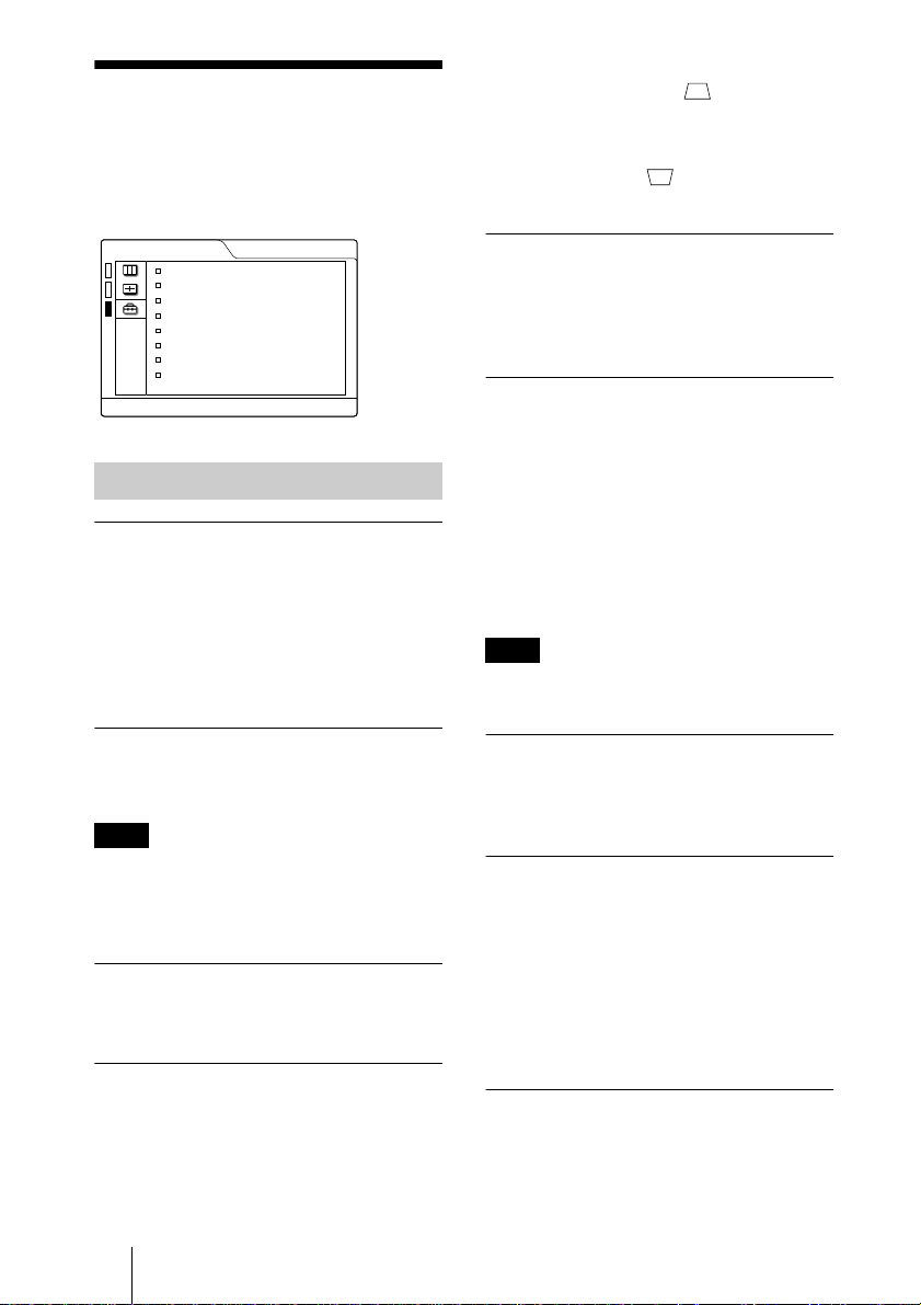
The SET SETTING Menu
The SET SETTING menu is used for
changing the settings of the projector.
SET SETTING
STATUS: ON
INPUT-A: RGB
KEYSTONE MEMORY:
DIGITAL KEYSTONE:
LANGUAGE: ENGLISH
INSTALLATION:
POWER SAVING
SIRCS RECEIVER:
LAMP TIMER: 000
ON
OFF
FLR-FRONT
: OFF
FRONT&REAR
Menu Ite m s
STATUS (on-screen display)
Sets up the on-screen display.
ON: Shows all of the on-screen displays.
OFF: Turns off the on-screen displays
except for the menus, a message when
turning off the power, and warning
messages.
INPUT-A
10h
When the downside of the trapezoid is
longer than the upside : Sets to a
minus value.
When the upside of the trapezoid is longer
than the downside : Sets to a plus
value.
LANGUAGE
Selects the languag e used in the menu and
on-screen disp lays. Availabl e languages a re:
English, French, German, Italian, Spanish,
Japanese and Chinese.
INSTALLATION
Sets to reverse the picture horizonta lly or
vertically.
FLR-FRONT: The picture is not reversed.
CEIL.-FRT: The picture is reversed
horizontally and vertically.
FLOOR-REAR: The picture is reversed
horizontally.
CEIL.-REAR: The picture is reversed
vertically.
Note
In case of using a mirror, be careful of
installation since the pictu re may be revers ed .
INPUT-A
Selects th e RGB or componen t si g nal inpu t
from the INPUT A connector.
Note
If the setting is no t correct, “Please check
INPU T -A setting.” appears on the screen and
the color of the picture becomes strange or the
picture is not displayed.
KEYSTONE MEMORY
Memorizes the data adjusted with DIGITAL
KEYSTONE.
DIGITAL KEYSTONE
Adjusts trapezoidal distortion of the picture
that may occur depending on the projection
angle.
GB
The SET SETTING Menu
30
POWER SAVING
When set to ON, the projector goes into
power saving mode if no signal is input for
10 minutes.
SIRCS RECEIVER
Selects the remote control detectors (SIRCS
receiver) on the front and rear of the
projector.
FRONT & REAR: Activates both the front
and rear detector s .
FRONT: Activates the front detector only.
REAR: Activates the rear detector only.
LAMP TIMER
Indicates the total number of hours for which
the lamp currently used has been operated.
 Loading...