

Sony VPH-G90E,VPH-G90U,VPH-G90M Installation Manual

VPH-G90E/VPH-G90M/VPH-G90U
3-865-264-13 (2)
Multiscan Pr ojector
Installation Manual for Dealers
Manuel d’installation destiné aux revendeurs
Manual de instalación para proveedores
CAUTION
THIS INSTALLATION MANUAL IS FOR USE BY QUALIFIED PERSONNEL
ONLY.
IMPORTANT
CE MANUEL D’INSTALLATION EST DESTINÉ AUX PROFESSIONNELS
SEULEMENT.
IMPORTANTE
ESTE MANUAL DE INSTALACIÓN ES PARA SER USADO POR PERSONAL
CUALIFICADO SOLAMENTE.
GB
FR
ES
VPH-G90E
VPH-G90M
VPH-G90U
©1998 by Sony Corporation

English
Table of contens
Table of Contents
Installation
Installation Procedures...............................................5 (GB)
Before Installation .......................................................6 (GB)
Using the Handles to Carry the Projector ........................ 6 (GB)
Necessary Clearance for Installation and Maintenance ... 7 (GB)
Notes on Screen ............................................................. 10 (GB)
Installation Diagrams ................................................12 (GB)
Floor Installation Using Front Projection Flat Screen ...12 (GB)
Ceiling Installation Using Front Projection Flat
Screen........................................................................ 14
Floor Installation Using Rear Projection Flat Screen .... 16 (GB)
Modifying Parts..........................................................18 (GB)
Opening the Upper Cover ..............................................18 (GB)
Using the Adjusters........................................................ 19 (GB)
Changing the Polarity..................................................... 20 (GB)
Adjusting the CRT Conversion Angle ........................... 22 (GB)
(GB)
Connections
Before Adjustment
Location and Function of the Rear Panel................24 (GB)
Switching the 75-ohm Terminate Connectors
(VPH-G90M/G90U only) ........................................ 27
Connecting Directly to the Projector ....................... 29 (GB)
Connecting Multiple Projectors................................30 (GB)
Using the PC-3000 Signal Interface Switcher .........32 (GB)
Confirming the System Construction............................. 37 (GB)
Using the PC-1271/1271M Signal Interface
Switcher ................................................................. 38
For Remote Control...................................................42 (GB)
Preparation of the Remote Commander......................... 42 (GB)
Keys on the Remote Commander .................................. 46 (GB)
Using the MENU.........................................................50 (GB)
Basic Menu Operation...............................................50 (GB)
Menu Modes .................................................................. 51 (GB)
The PIC CTRL (Picture Control) Menu......................... 55 (GB)
The PIC SETTING 1 (Picture Setting 1) Menu............. 57 (GB)
The PIC SETTING 2 (Picture Setting 2) Menu............. 58 (GB)
The INPUT SETTING Menu......................................... 59 (GB)
The SET SETTING 1 Menu .......................................... 62 (GB)
The SET SETTING 2 Menu .......................................... 63 (GB)
(GB)
(GB)
2 (GB) Table of Contents

Adjustments
The INPUT INFO (Information) Menu .........................65 (GB)
The INPUT MEM. (memory) OPTION Menu ..............66 (GB)
The SET INFO (information) Menu .............................. 68 (GB)
The SERVICE SETTING 1 Menu ................................. 68 (GB)
The SERVICE SETTING 2 Menu ................................. 69 (GB)
The SERVICE SETTING 3 Menu ................................. 70 (GB)
The PIC ORBITING Menu............................................ 71 (GB)
The INT. OSC (internal oscillation) SETTING Menu... 71 (GB)
The TIMER Menu.......................................................... 72 (GB)
The UNIFORMITY Menu ............................................. 72 (GB)
The ABL (Automatic Brightness Limiter) LINK
Menu .........................................................................74
(GB)
T est Patterns..............................................................75 (GB)
Test Patterns ................................................................... 75 (GB)
Test Patterns in Each Mode............................................ 76 (GB)
Warm-up before adjustment.....................................77 (GB)
Adjustment Procedure .............................................. 78 (GB)
Adjusting the Lens Focus and Scheimpflug...........81 (GB)
Preparation .....................................................................81 (GB)
Adjusting the Green Lens Focus and Scheimpflug........ 81 (GB)
Adjusting the Red Lens Focus and Scheimpflug ........... 85 (GB)
Adjusting the Blue Lens Focus and Scheimpflug .......... 86 (GB)
Adjusting the Magnetic Focus ................................. 87 (GB)
Saving the Standard Magnetic Focus Data ....................92 (GB)
Adjusting the Registration........................................93 (GB)
Preparation .....................................................................93 (GB)
Keys for Adjusting ......................................................... 94 (GB)
Adjusting the Green Registration................................... 95 (GB)
Adjusting the Red Registration .................................... 108 (GB)
Adjusting the Blue Registration................................... 119 (GB)
Saving the Standard Registration Data ........................ 121 (GB)
Fine Adjustment for Each Input Signal..................122 (GB)
Selecting the Input Signal ............................................122 (GB)
Fine Magnetic Focus and AQP/DQP Adjustments ...... 122 (GB)
Fine Registration Adjustment....................................... 122 (GB)
SIZE Adjustment.......................................................... 123 (GB)
SHIFT Adjustment ....................................................... 123 (GB)
Blanking Adjustment.................................................... 124 (GB)
Adjusting the White Balance ....................................... 125 (GB)
GB
English
(continued)
Table of Contents 3 (GB)

Table of contens
Others
Adjusting the Picture Quality .................................129 (GB)
Saving the Adjustment Data...................................130 (GB)
Memory Blocks............................................................ 130 (GB)
Saving the Data to the Service Block........................... 132 (GB)
Input Memory .............................................................. 133 (GB)
Video Memory ............................................................. 137 (GB)
Resetting the Data ................................................... 138 (GB)
Resetting the Item in Adjustment Only
(Normal Reset)........................................................ 138
(GB)
Resetting Multiple Items Simultaneously
(All Data Reset) ...................................................... 139
(GB)
Setting the Index Numbers ..................................... 141 (GB)
Link Functions ......................................................... 145 (GB)
Using the Linked ABL Function ..................................145 (GB)
Using the Linked Picture Orbiting Function................ 148 (GB)
Self-diagnosis Function..........................................151 (GB)
List of the Projection Distance by Angle
of Optical Axis..................................................... 153
(GB)
Index .........................................................................159 (GB)
4 (GB) Table of Contents

Installation
Installation Procedures
By default, this projector is adjusted for 120-inch front projection on the
floor/desk. If you install the projector in other conditions, you have to
change some settings. Therefore, installation procedures depend on the
screen size or type, and installation method.
1 Verify the conditions of installation, such as angle of optical axis,
projection distance, height of the projector and screen.
2 Change the polarity according to the projection patterns.
3 Install the projector and screen.
4 Adjust the lens focus approximately.
5 Reset the registration data to the factory setting.
6 Adjust the CRT conversion angle.
7 Connect external video equipment.
The installation is completed.
Installation
.
(page 20 (GB))
.
(page 12 (GB))
.
(page 81 (GB))
.
(page 138 (GB))
.
(page 22 (GB))
.
(page 24 (GB))
.
Then perform the adjustments following the adjustment
procedure.
(page 78
(GB)
)
Installation 5 (GB)

Before Installation
Before Installation
Using the Handles to Carry the Projector
Installation
Using the handles
Carry the projector with four persons or more by using the front, rear and
side (right and left) handles.
Pull out the front and rear handles or the side handles.
Putting away the handles
Push the handle release lever under each handle. The handle is
automatically retracted.
6 (GB) Installation

Necessary Clearance for Installation and Maintenance
Make sure to provide enough room for maintenance service. Install the
projector, making reference to the dimensions below.
Note
There should be a space of at least 30 cm (1 3/16 inches) around the
ventilation holes at the rear. Never block the holes with any material.
Front
750 (29 5/8)
Remote control
detector
Ventillation holes
/8)
7
21.5
(
Installation
Mass: 110 kg (242 lb 8 oz)
Rear
Remote control detector
STANDBY indicator
LED window
226 (9)
774 (30 1/2)
198.5 (7 7/8)
601.5 (23 3/4)
35 (1 7/16)
/8)
7
70.5 (2
ON indicator
Ventillation holes
/8)
7
96.8
(3
/16)
9
/8)
5
(6
167.4
39 (1
99 (4)
Unit: mm (inches)
Unit: mm (inches)
Installation 7 (GB)
Before Installation
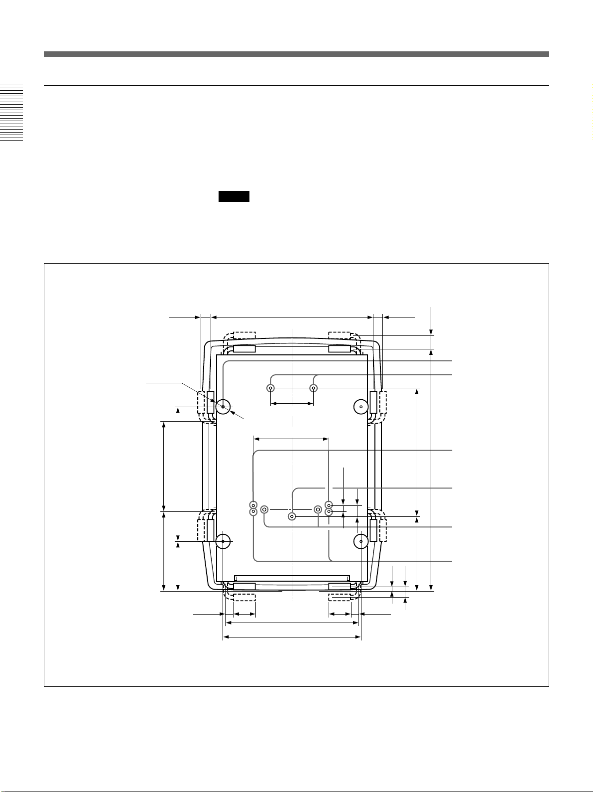
Bottom
Installation
The standard hole for installation on the bottom surface is useful for
reference when measuring for installation. There are seven holes on the
bottom surface of the projector. For ceiling installation using the optional
PSS-90 Projector Suspension Support, use five holes to attach the PSS-90.
The other two holes are spare ones.
Notes
•Use only the M8 meter screws of 10 mm (13/32 inches) to 30 mm (1 3/16
inches) long for the attachment holes for the PSS-90.
25
•When attaching the PSS-90, use the M8 meter screws of 20 mm (
/32
inches) supplied with the PSS-90.
4-∅60
8)
/
1
8)
/
5
384 (15
573 (22
2)
/
1
/8)
3
340.5 (13
211.5 (8
40 (1 5/8)
679 (26 3/4)
174 (6 7/8)
322 (12 3/4)
25 (1)
40 (1 5/8)
50 (2)
/32)
21
16.5 (
/8)
5
547 (21
/4)
1
308.5
(12
50 (2)
Hole for attaching an
adjuster
(M10 meter screw,
50 (2)
Max 30 mm (1 3/16
inches))
Holes for attaching
the PSS-90
(M8 meter screws,
/8)
5
20 mm (25/32 inches))
Holes for attaching
the PSS-90
1031.6 (40
(M8 meter screws,
20 mm (25/32 inches))
Hole for attaching
the PSS-90
(M8 meter screw, 20
mm (25/32 inches))
(Standard hole for
installation)
Receptacles for the
projections on the PSS90
Spare holes for
installation
8 (GB) Installation
35 (1 7/16)
90
(3 5/8)
550 (21 3/4)
580 (22 7/8)
90
(3 5/8)
35 (1 7/16)
Unit: mm (inches)
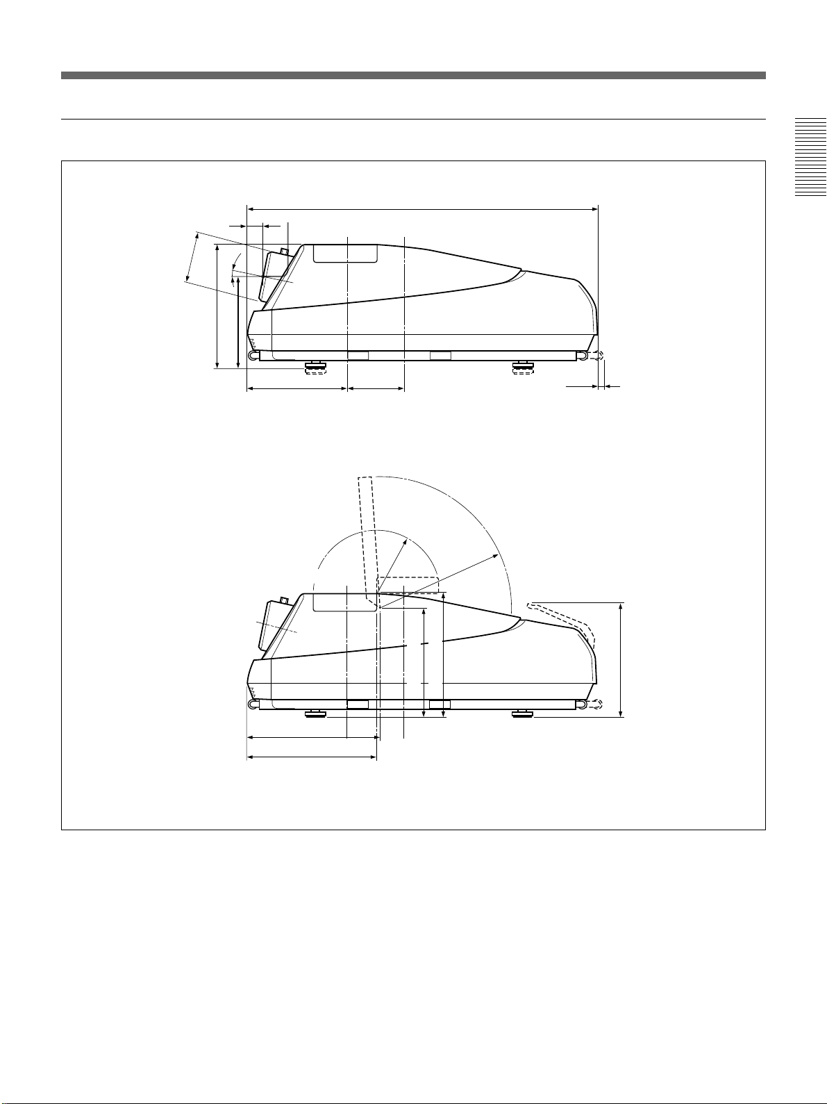
Side
)
4
/
1
(6
∅157.5
/4)
1
385.5 (15
With the covers open
Location of the standard hole for installation
Location of the standard
hole for installation
11.9°
/2)
1
289 (11
308.5 (12 1/4)168
1066 (42)
Center of projection balance
(6 5/8)
)
4
/
3
R 196
7
(
R 411
16
(
Installation
16.5 (21/32)
)
1
4
/
401.2 (15 7/8)
415.8 (16 3/8)
/4)
1
2)
/
1
385.3 (15
340 (13
Center of projection balance
354 (14)
Unit: mm (inches)
Installation 9 (GB)
Before Installation
Notes on Screen
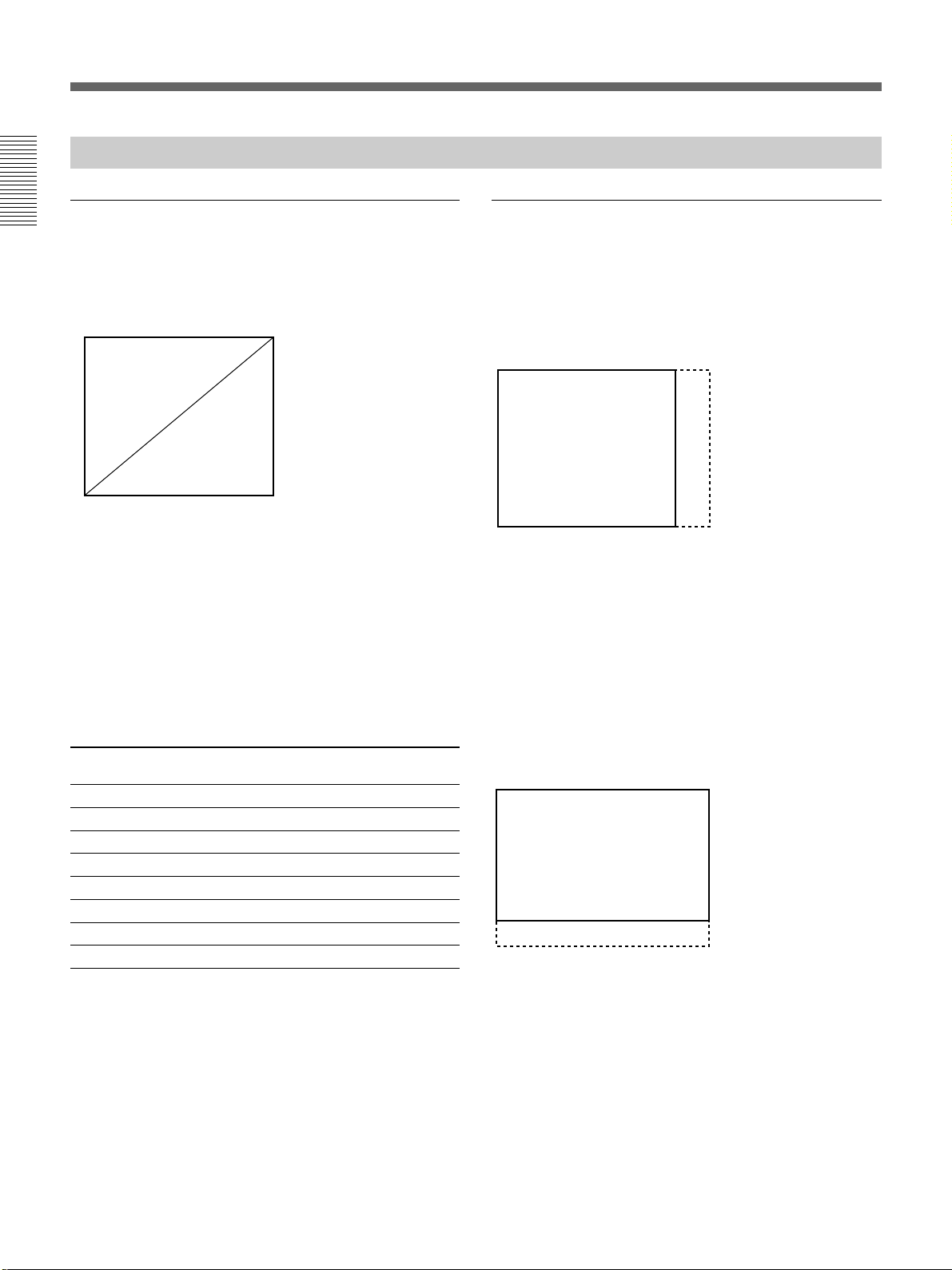
Screen size
Installation
The screen size is the diagonal length of the screen in
inches, while the aspect ratio of the screen is 4:3. The
ratio of the screen height, width, and diagonal is 3:4:5.
4
3
If you use a screen with 4:3 aspect ratio whose size is
not given in the table below, you can calculate the
screen height and width from the screen size (inches)
as follows.
Calculate at the conversion rate of 25.4 mm to the
inch.
Height (mm) = Screen size × 25.4 ×
Width (mm) = Screen size × 25.4 × 4/5
Screen size and dimensions
Screen size (inches)
(Diagonal) Height (mm) Width (mm)
100 1524 2032
120 1829 2438
150 2286 3048
180 2743 3658
200 3048 4064
250 3810 5080
300 4572 6096
5
3
/5
90 1372 1829
Screens with an aspect ratio other than
4:3
When the height is greater
Calculate the screen size with 4:3 aspect ratio from the
screen height as shown below. Install the projector and
screen in accordance with the screen size obtained.
--- : Screen whose aspect ratio is 4:3
5
Screen size (inch) = (height (mm) ×
Example: When the screen height is 1500 mm
5
(1500 (mm) ×
/3) × 1/25.4 = Approx. 98 inches
When the width is greater
Calculate the screen size with 4:3 aspect ratio from the
screen width as shown below. Install the projector and
screen in accordance with the screen size obtained.
---: Screen whose aspect ratio is 4:3
/3) × 1/25.4
10 (GB) Installation
5
Screen size (inch) = (width (mm) ×
/4) × 1/25.4
Example: When the screen width is 2000 mm
5
(2000 (mm) ×
/4) × 1/25.4 = Approx. 98 inches

Types of screen
Front projection screen for floor installation
The bead screen is recommended. A screen of this type
reflects the brightest light.
Bead
screen
Center of the screen
Brightest picture
Projector
Front projection screen for ceiling installation
The silver screen is recommended. You can get a
picture that is two to four times brighter than that of
the white screens.
Silver
screen
Projector
Rear projection screen
A screen manufactured using two sheets, the fresnel
and lenticular, is recommended for a bright and clear
full-screen picture projection.
Screen
Projector
Horizontal viewing area
White screen
When viewers watch the projected picture in a wide
area, you can obtain a picture that appears equally
bright from all parts of the room using the white screen
for both floor and ceiling installations. Note that you
will not be able to get a clear picture in this case unless
the room is dark.
Installation
Center of the screen
Brightest picture
Projector
Installation 11 (GB)
Before Installation
Installation Diagrams
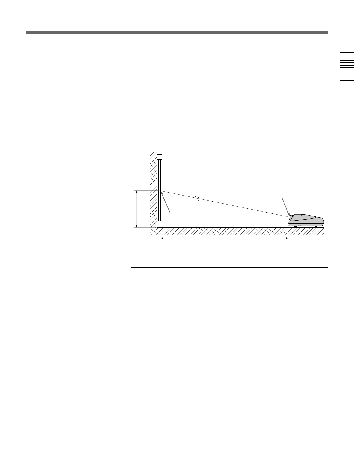
Floor Installation Using Front Projection Flat Screen
Be sure that the projector is level to the floor.
Installation
Wall
G
A
D
13.6˚
B
Center of the screen
C
H
E
B: Difference in height between the projector’s bottom surface and the center of the screen
E: Horizontal distance between the center of the screen and the center of the green lens
F: Horizontal distance between the center of the screen and the standard hole for installation
H: Horizontal distance between the center of the screen and the projector’s front surface
Tolerances
B: ±5%
Other measurements: 0% to +5%
Center of the green lens
Standard hole
for installation
Floor
F
The distances in gray are the factory preset settings. Unit:mm (inches)
Screen size 90 100 120 150 180 200 250 300
(inches)
A (Vsize) 1372 1524 1829 2286 2743 3048 3810 4572
(54 1/8) (60) (72 1/8) (90) (108) (120) (150) (180)
B (Hcent) 899 959 1084 1296 1497 1630 1950 2294
(35 1/2) (37 7/8) (42 3/4) (51 1/8) (59) (64 1/4) (76 7/8) (90 3/8)
C (Width)
28
a)
32
b)
(1 1/8) (1 5/16)
D (TD) 2587 2847 3373 4285 5137 5702 7065 8533
(101 7/8) (112 1/8) (132 7/8) (168 3/4) (202 1/4) (224 1/2) (278 1/4) (336)
E (Xlens) 2514 2767 3278 4165 4993 5542 6867 8294
(99) (109) (129 1/8) (164) (196 5/8) (218 1/4) (270 3/8) (326 5/8)
F (Lhole) 2764 3017 3528 4415 5243 5792 7117 8544
(108 7/8) (118 3/4) (138 7/8) (173 7/8) (206 3/8) (228) (280 1/4) (336 3/8)
G (Lmax) 3520 3773 4284 5171 5999 6548 7873 9300
(138 5/8) (148 5/8) (168 3/4) (203 5/8) (236 1/4) (257 7/8) (310) (366 1/4)
H (Lfront) 2455 2708 3219 4106 4934 5483 6808 8235
(96 5/8) (106 5/8) (126 3/4) (161 5/8) (194 1/4) (215 7/8) (268) (324 1/4)
a) Sony VPS-100FM
b) Sony VPS-120FH and VPS-120FM
12 (GB) Installation
When the Screen Size is not Mentioned in the Tables
You can calculate the installation measurements described below when
you use the screen whose size is not mentioned in the tables on pages
(GB) and 14 (GB).
12
Check your installation conditions:
•Screen size to be used (S)
•Installation measurements at the end of the manual, ES and BS for
smaller screen size and EL and BL for larger screen size
See the tables on pages 153 (GB) to 158 (GB).
B
Center of the screen
Installation
Center of the green lens
E
E: Projection distance
B: Screen heights
Now you can calculate the installation measurements as follows:
E (mm) = ES + ((S – smaller screen size) × (EL – ES) × 0.1)
B (mm) = BS + ((S – smaller screen size) × (BL – BS) × 0.1) + 289
Example: when using 124-inch screen
According to the tables on page 154
(GB), the values E and B are as
follows:
ES = 3279, BS = 791 (As the smaller screen size is 120 inch.)
EL = 3570, BL = 861 (As the smaller screen size is 130 inch.)
Therefore,
E (mm) = 3279 + ((124 –120) × (3570 – 3279) × 0.1) = 3395.4 (mm)
B (mm) = 791 + ((124 – 120) × (861 – 791) × 0.1) + 289 = 1108 (mm)
Installation 13 (GB)
Before Installation
Installation Diagrams
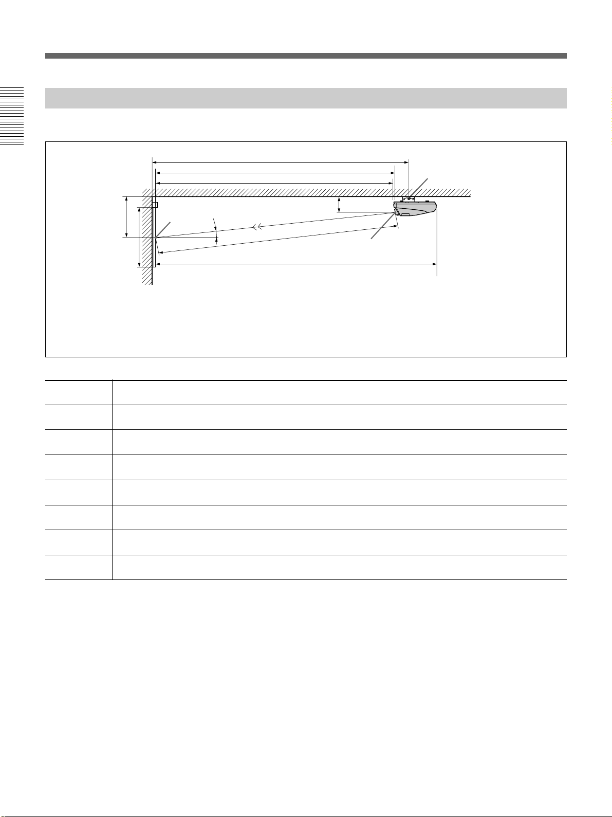
Ceiling Installation Using Front Projection Flat Screen
Use the PSS-90 Projector Suspension Support (not supplied).
Installation
Center of
B
A
Screen size 90 100 120 150 180 200 250 300
(inches)
A (Vsize) 1372 1524 1829 2286 2743 3048 3810 4572
B (Hcent) 990 1050 1175 1387 1588 1721 2041 2385
D (TD) 2587 2847 3373 4285 5137 5702 7065 8533
(101 7/8) (112 1/8) (132 7/8) (168 3/4) (202 1/4) (224 1/2) (278 1/4) (336)
E (Xlens) 2514 2767 3278 4165 4993 5542 6867 8294
F (Lhole) 2932 3185 3696 4583 5411 5960 7285 8712
G (Lmax) 3520 3773 4284 5171 5999 6548 7873 9300
H (Lfront) 2455 2708 3219 4106 4934 5483 6808 8235
the screen
Wall
(54 1/8) (60) (72 1/8) (90) (108) (120) (150) (180)
(39) (41 3/8) (46 3/8) (54 5/8) (62 5/8) (67 7/8) (80 3/8) (94)
(99) (109) (129 1/8) (164) (196 5/8) (218 1/4) (270 3/8) (326 5/8)
(115 1/2) (125 1/2) (145 5/8) (180 3/8) (213) (234 5/8) (286) (342)
(138 5/8) (148 5/8) (168 3/4) (203 5/8) (236 1/4) (257 7/8) (310) (366 1/4)
(96 5/8) (106 5/8) (126 3/4) (161 5/8) (194 1/4) (215 7/8) (268) (324 1/4)
13.6˚
E: Horizontal distance between the center of the screen and the center of the green lens
H: Horizontal distance between the center of the screen and the projector’s front surface
Tolerances
F
E
H
380 (15)
D
Center of the green lens
G
B: ±5%
Other measurements: 0% to +5%
Rotation axis of
the PSS-90
Ceiling
Unit:mm (inches)
14 (GB) Installation
Necessary parts modifications
Changing the polarity used for “Ceiling installation, front projection”
For details, see “Changing the Polarity” on page 20 (GB).
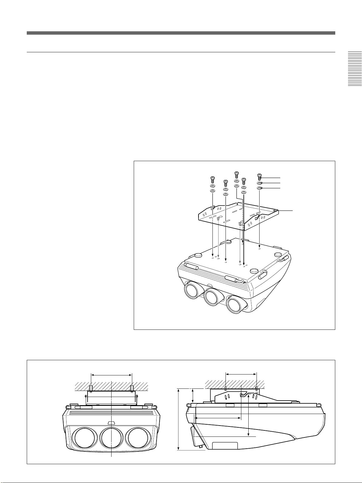
Attaching the PSS-90 Projector Suspension Support
Attach the projector mounting bracket to the bottom surface of the
projector.
Use five each of the M8×20 bolts, M8 washers and spring washers, all of
which are supplied with the PSS-90.
1 Align the two projections on the projector mounting bracket with the
receptacles on the bottom surface of the projector.
2 Fasten the five bolts and washers to fix the mounting bracket to the
five holes for attaching the PSS-90 on the bottom surface of the
projector.
Installation
M8×20 bolt
Spring washer
M8 washer
Projector
mounting
bracket
Installation dimensions
254 (10)
For attaching the PSS-90 to the ceiling, refer to the Installation Manual of the
PSS-90 Projector Suspension Support.
254 (10)
/8)
5
(4
114.8
)
8
/
7
18
415.8 (16 3/8)
476.3 (
)
4
/
1
333.7
(13
Unit: mm (inches)
Installation 15 (GB)
Before Installation
Installation Diagrams
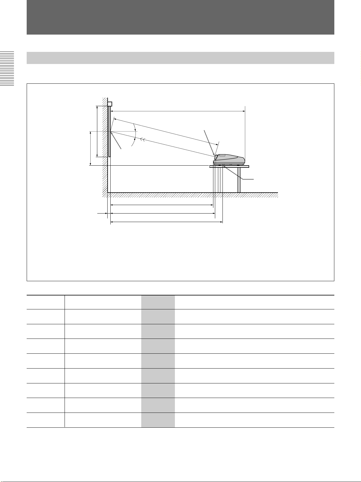
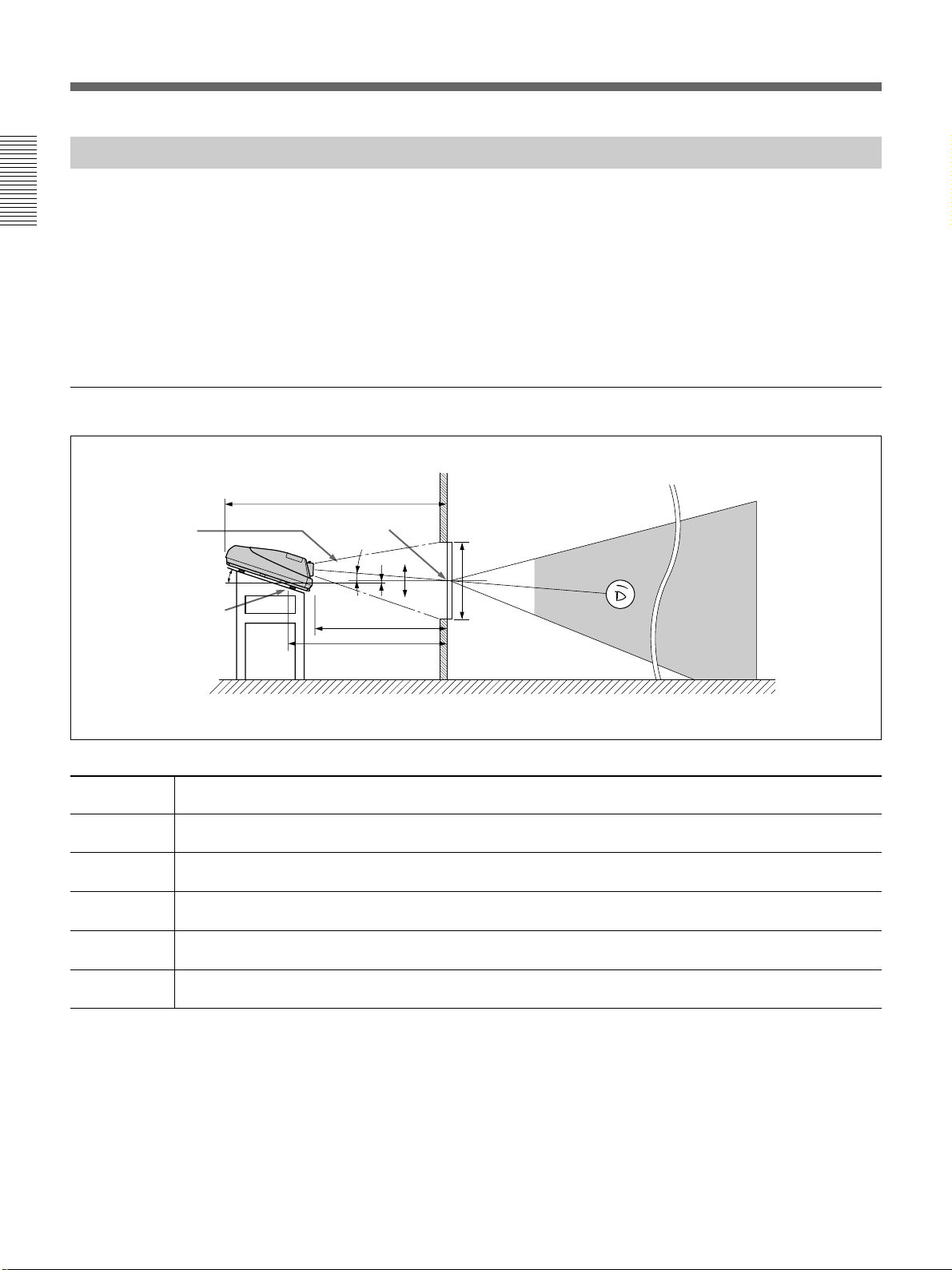
Floor Installation Using Rear Projection Flat Screen
Installation
When the optical axis angle is 2°
Optical axis
angle
14.6°
Standard hole for
installation
What is the optical axis angle?
The optical axis angle is the angle between the horizontal level line and the
straight line from the center of the projector’s green lens to the center of
the screen. When using a rear projection screen, you can get the brightest
picture when the center of the screen is aligned with a straight line
extension of the center of the green lens.
Therefore, the most suitable optical axis angle varies depending on the
height of the screen and your line of sight.
G
Center of the screen
2°
E
F
Wall
–
B
0
+
A
Floor
Unit: mm (inches)
Screen size 90 100 120 150 180 200 250 300
(inches)
A (Vsize) 1372 1524 1829 2286 2743 3048 3810 4572
B (Hcent) 95 86 67 36 6 –13 –60 –111
E (Xlens) 2567 2826 3348 4252 5097 5659 7011 8467
F (Lhole) 2873 3132 3653 4558 5402 5964 7316 8772
G (Lmax) 3594 3853 4375 5279 6124 6686 8038 9494
(54 1/8) (60) (72 1/8) (90) (108) (120) (150) (180)
(3 3/4) (3 1/2) (2 3/4) (1 7/16)(
(101 1/8) (111 3/8) (131 7/8) (167 1/2) (200 3/4) (222 7/8) (276 1/8) (333 3/8)
(113 1/8) (123 3/8) (143 7/8) (179 1/2) (212 3/4) (234 7/8) (288 1/8) (345 3/8)
(141 1/2) (151 3/4) (172 1/4) (207 7/8) (241 1/8) (263 1/4) (316 1/2) (373 7/8)
1
/4) (– 17/32) (–2 3/8) (–4 3/8)
Necessary parts modifications
Changing the polarity used for “Floor installation, rear projection”
For details, see “Changing the Polarity” on page 20 (GB).
16 (GB) Installation

Variable Range of the Optical Axis Angle in Rear Projection
You can change the optical axis angle within the following ranges by
adjusting the scheimpflug.
For adjusting the scheimpflug, see page 83 (GB).
On floor installation
You can install the projector within an angle of optical axis –13.6° to +2°.
Wall
+2°
–13.6°
Installation
: Optical axis
: Horizontal line
Floor
+13.6°
On ceiling installation
You can install the projector within an angle of optical axis +3° to +13.6°.
Ceiling
+3°
: Optical axis
: Horizontal line
Wall
Installation 17 (GB)
Modifying Parts
Modifying Parts
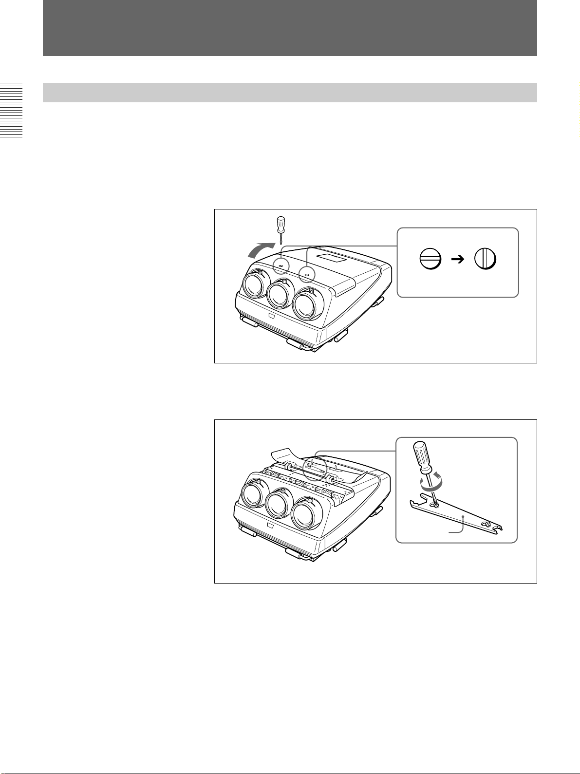
Opening the Upper Cover
Installation
Most modifications can be performed only by opening the
upper cover.
1 Turn off the main power of the projector.
2 Unlock the two screws on the projector by using a screwdriver, and
then open the upper cover.
Locked Unlocked
To remove the supplied tool
The tool is located on the back of the upper cover.
Loosen the screw by using a screwdriver and remove the tool.
Tool
18 (GB) Installation
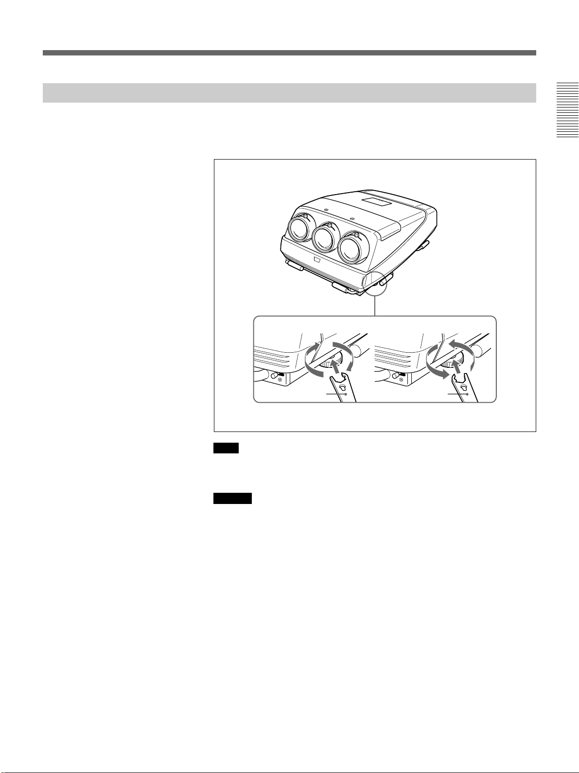
Using the Adjusters
When the projector installation location is not horizontal, adjust the
adjusters so that the projector is placed horizontally.
Use the supplied tool to turn the adjuster.
Installation
To lower
Turn counterclockwise
Supplied tool
Note
To raise
Supplied tool
Turn clockwise
The supplied tool can rotate the screw in one direction only. To rotate the
screw in the reverse direction, turn the tool upside down.
Caution
Do not turn the tool forcibly when the screw has fully rotated. Otherwise,
the tool may slip out and injure your hand.
Installation 19 (GB)

Modifying Parts
Changing the Polarity
Installation
How to change the polarity
The polarity of the projector is adjusted at the factory to use the projector
for front projection on the floor.
When the projector is installed on the ceiling or used in rear projection, it
is necessary to change the settings of the polarity switches.
1 Turn off the power of the projector.
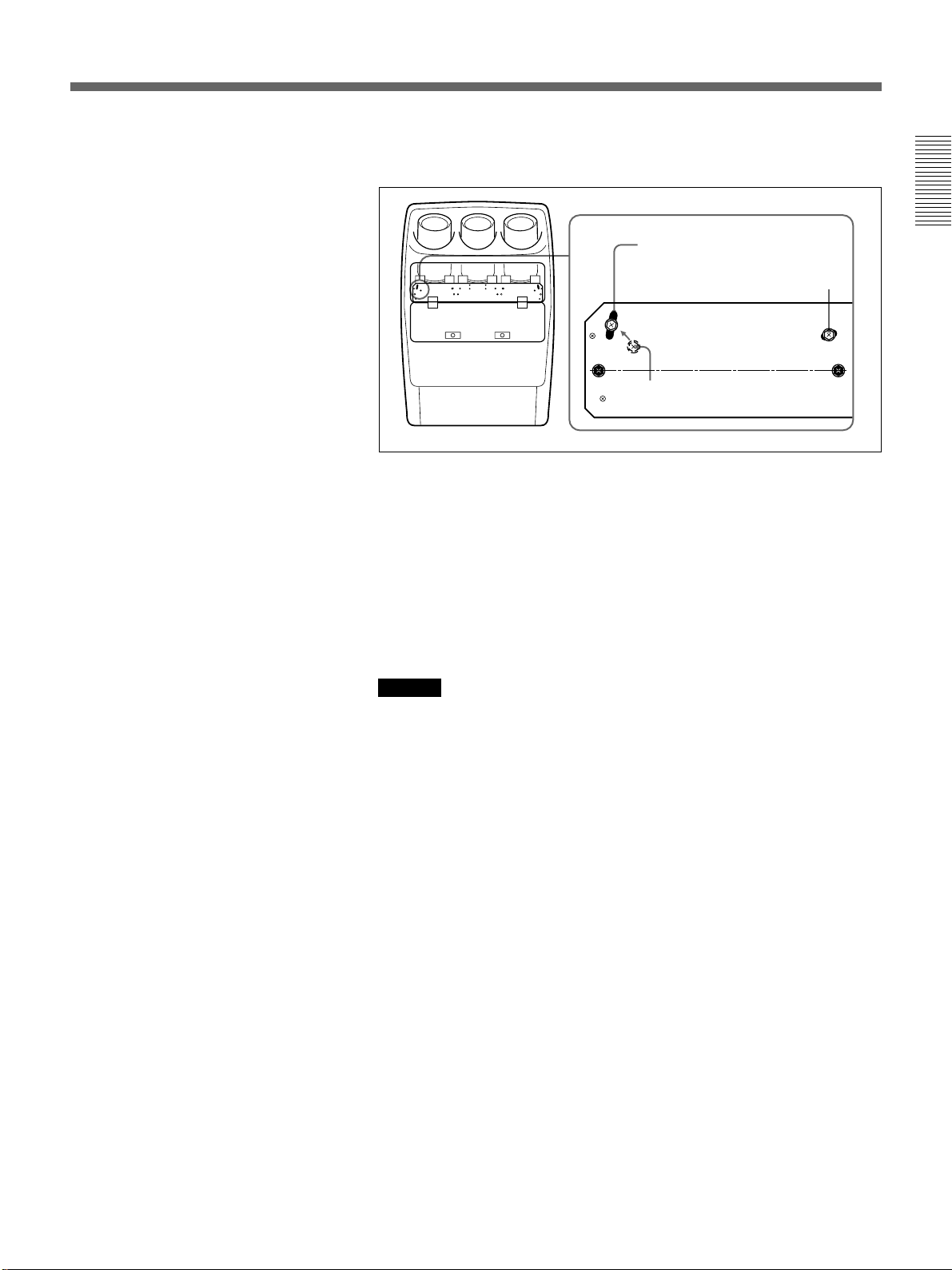
2 Open the control panel cover, loosen the screw, and open the cover of
the polarity switches.
Push the control panel cover and
slide it to open.
Loosen
Open
R
L
3 Change the position of the polarity switches (V and H switches), if
necessary.
H switch
V switch
R
Right
20 (GB) Installation
L
Upper
Lower
Left
4 Close the cover of the polarity switches, tighten the screw and close
the control cover.
Note
If the cover of the polarity switches does not shut firmly, the power of the
projector is not turned on in order to protect the CRTs.
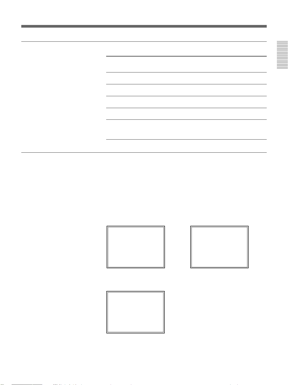
Installation methods and settings of the polarity switches
For optimum
performance,
white screen will
remain for
20min
For immediate use
push [MENU] key.
Polarity and on-screen display
Installation
methods
Position of the
V switch
Position of the
H switch
On-screen display
by default (See
below.)
Front projection,
Upper Left Correct
floor
Front projection,
Lower Right C
ceiling
Rear projection,
Upper Right A
floor
Rear projection,
Lower Left B
ceiling
Others Display letters on the screen so that you can determine
which changes to make.
For on-screen display and necessary changes, see below.
When the projector is installed on the ceiling or used in rear projection
without changing the polarity, one of the following on-screen displays
appears. In this case, you have to change the polarity corresponding to the
installation methods.
Installation
A The letters are backward.
B The letters are upside
down.
Change the position
of the H switch.
For optimum
performance,
white screen will
remain for
20min
For immediate use
push [MENU] key.
Change the position of the V
switch.
C The letters are upside down and backward.
Change the positions of the H and V switches.
push [MENU] key.
For immediate use
20min
remain for
white screen will
performance,
For optimum
Installation 21 (GB)
Modifying Parts
Adjusting the CRT Conversion Angle
Installation
Adjust the CRT conversion angle so that the three CRT images converge
exactly.
1 Open the upper cover.
For details, see “Opening the Upper Cover” on page 18 (GB).
2 Turn on the power of the projector.
3 Set the remote commander to the service mode.
For details, see “Preparation of the Remote Commander” on page 42 (GB).
4 Reset the green, red and blue centering.
For details, see “Resetting the Data” on page 138 (GB).
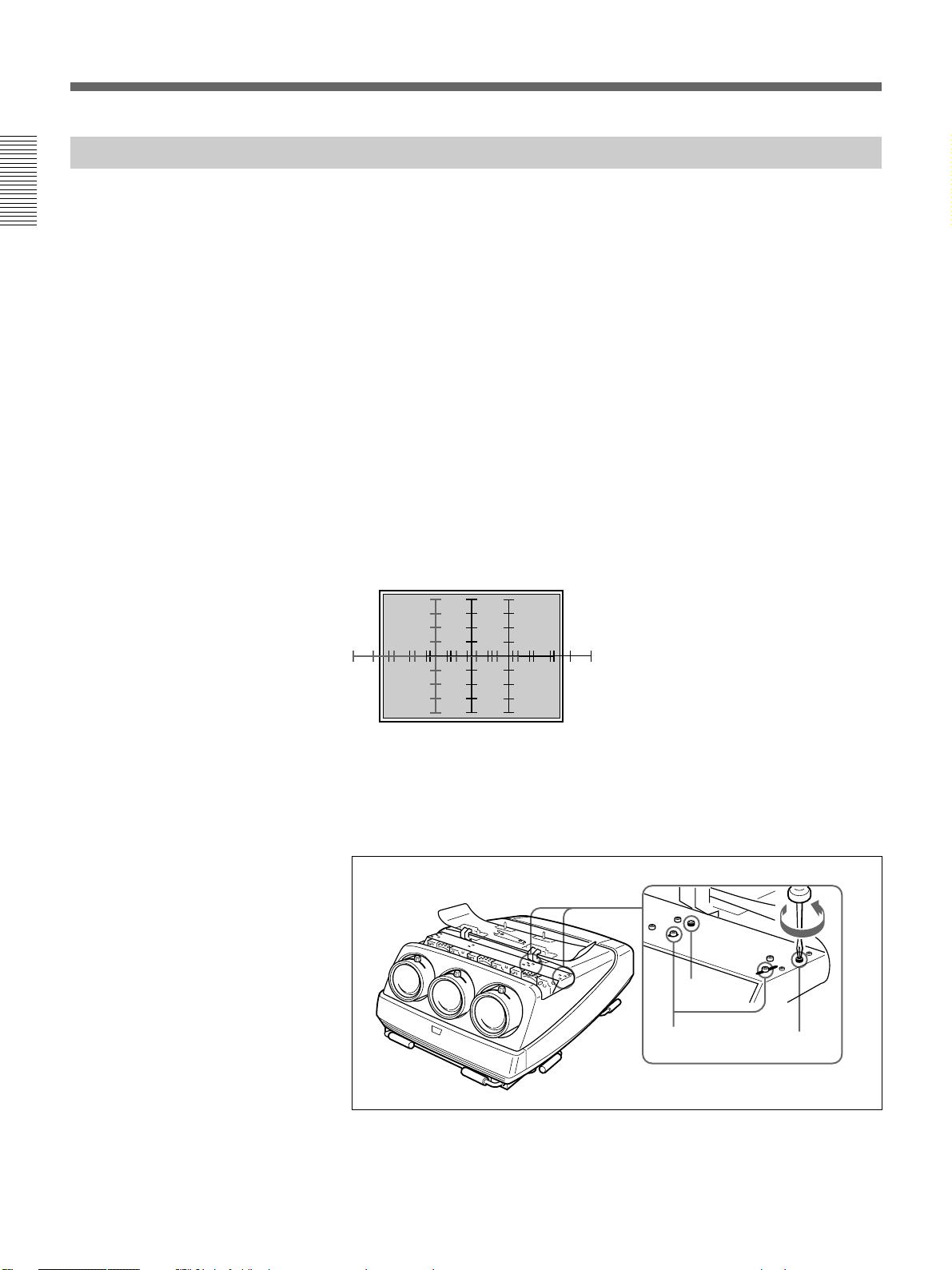
5 Make sure that the on-screen display is shown as follows:
•The center of the green hatch pattern aligns with the horizontal center
of the screen.
•The center of the red and blue hatch patterns align at even intervals
from the green hatch pattern.
If the center of the green hatch pattern does not align with the center of
the screen, re-install the projector correctly.
6 Loosen the two red CRT fixing screws (black) by using a Philips-head
screwdriver. Make sure not to remove the screws.
120
S
L
Black
screw
Adjustment
screws (gold)
Black screw
22 (GB) Installation
7 Insert the two adjustment screws (gold) into the appropriate adjustment
holes corresponding to the screen size.
Example: Red CRT
For 90–300 inch screens
Loosen.
S
Move.
L
120
For 120 inch screens (by default)
By default, the two adjustment screws (gold) are fixed to the two
adjustment holes for 120 inch screens.
For 90 and 300 inch screens other than 120 inch ones, remove the
adjustment screw from the 120 inch hole and insert it into the elliptic
hole for 90–300 inch screens. Then, loosen the other adjustment screw.
8 For screens other than 120 inch screens, move the red CRT right and
left so that the vertical line of the red cross hatch pattern converges
with the green pattern, then tighten the two adjustment screws (gold).
Caution
When moving the CRT, do not insert your hands into the small
opening between the lenses. Doing so may injure your hand.
Installation
9 Tighten the two red CRT fixing screws (black).
10Repeat steps 6 to 9 to loosen the two blue CRT fixing screws (black),
adjust the blue CRT conversion angle and tighten the two adjustment
screws (gold).
Installation 23 (GB)
Connections
Connections
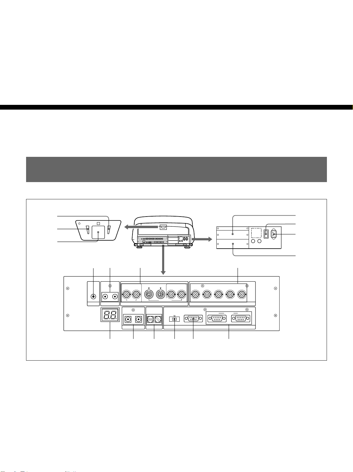
Location and Function of the Rear Panel
5
STANDBY ONR
6
7
!¡ !º 9 8
OUT
OUT
IN
S VIDEO
VIDEO
DEVICE INDEX
TRIGGER
LINK
OUT
IN
VIDEO
IN
PLUG IN POWER
CONTROL S
IN
OUT
!™ !£ !¢ !∞ !§ !¶
1 Signal interface board attachment part (INPUT
B)
An optional signal interface board such as IFB-12/12A
and IFB-40 can be attached to this section.
When the IFB-12/12A is attached, the signal input to
the INPUT A connectors can be output from the IFB12/12A by setting it to output mode.
Y IN
RS-232C RS-422A
C IN
R
RS-232C/422A
Y
REMOTE
B-Y/P
B
INPUT A
IN OUTPJ COM
R
G B SYNC/HD VD
R-Y/P
2 MAIN POWER switch
3 AC IN socket
Connect the supplied AC power cord.
1
2
3
4
24 (GB) Connections

4 Signal interface board attachment part (INPUT
C)
An optional signal interface board can be attached to
this section.
Notes
• The IFB-40 cannot be attached to INPUT C.
•When the IFB-12/12A is attached, the IFB-12/12A
cannot be set to output mode.
5 ON indicator
When the projector is turned on, this indicator lights in
green.
!º LINK IN/OUT jacks (stereo minijack)
When connecting multiple projectors, connect the
LINK OUT jack to the LINK IN jack on another
projector. Then the link functions (ABL LINK, PIC
ORBITING LINK and SCAN LINE SHIFT LINK)
can be used.
For details of the link function, see pages 145 (GB) to 150
(GB).
!¡ TRIGGER connector (minijack)
When the projector is turned on, 12 V is output. When
it is turned off, 0 V is output. However, the connector
cannot be used as the power source.
Connections
6 u STANDBY indicator
When the MAIN POWER switch on the projector is
turned ON, this indicator lights in orange, indicating
that the projector can be turned on/off using the remote
commander.
7 Rear remote control detector
8 INPUT A connectors (BNC type)
R/R-Y/P
R, G/Y, B/B-Y/PB, SYNC/HD, VD
connectors: Connect to the outputs of a computer or a
video camera. According to the connected
equipment, the RGB (R, G, B), component (R-Y,
Y, B-Y) or HDTV (P
R, Y, PB) signal is selected.
9 VIDEO connectors*
VIDEO IN connector (BNC type): Connects to the
composite video output of the video equipment.
VIDEO OUT connector (BNC type): Connects to the
composite video input of a color monitor.
S VIDEO IN/OUT connectors (4-pin, mini-DIN
type): Connects to the S video output or input of the
video equipment.
Y IN, C IN connectors (BNC type): Connects to the
Y and C video outputs of the video equipment.
!™ LED display window
Self-diagnosis results and PJ COM communication
conditions, etc. are displayed using two-digit numbers
and alphabets.
Self-diagnosis codes are displayed in red or orange,
and the warning and communication conditions in
green.
For details, see “Self-diagnosis function” on page 151 (GB).
!£ CONTROL S jacks
IN/PLUG IN POWER jack (stereo minijack):
Connects to the CONTROL S OUT jack of other
Sony equipment. Also connects to the CONTROL
S OUT jack of the supplied remote commander
with the supplied remote control cable (stereo
cable) to be used as a wired remote control. In this
case, this jack supplies the power to the remote
commander to save the battery power.
OUT jack (stereo minijack): Connects to the
CONTROL S IN jack of other Sony equipment.
Note
When using this jack, the remote control detector on
the projector does not function.
Note
The S VIDEO IN connector is disconnected when a
cable is connected to the Y IN/C IN connectors.
* Note on the VPH-G90E model
The optional IFB-G90E Video Interface Board is
required for using the VIDEO connectors.
Connections 25 (GB)
Location and Function of the Rear Panel
!¢ DEVICE INDEX. switches
When multiple projectors are connected, set the device
index number of each projector.
To display the device index number on the screen,
press the NORMAL key, and the ENTER key on the
remote commander .
Note
Do not set the device index number to “00.” If you
do, the projector will not operate with the remote
Connections
commander.
You can operate the projector with the keys on the
control panel of the projector but the connected
equipment cannot be operated with the keys on the
control panel.
!∞ RS-232C/RS-422A selector
Selects the function of the RS-232C/RS-422A
connector.
!§ RS-232C/422A REMOTE connector (D-sub 9pin)
Used to expand the system connections using the RS232C/422A interface.
About the keys on the control panel
The control panel is located inside the cover on the top
of the projector. The locations and functions of the
keys on the control panel are the same as those on the
remote commander.
For the keys on the remote commander, see page 46 (GB).
The keys on the control panel are basically effective
for this projector only. Only the commands from the
SYS SET key and the switcher select commands are
transmitted to the connected equipment via the PJ
COM connector.
Note
If you set the device index number to “00,” the
commands from the SYS SET key and the switcher
select commands will not be transmitted to the other
equipment. Do not set the device index number to
“00.”
!¶ PJ COM (projector communication) IN/OUT
connectors (D-sub 9-pin)
These are the connectors conforming to the RS-485
standards, especially designed to expand the system
using Sony projectors.
Use these connectors to connect the PJ COM system of
the PC-3000 Signal Interface Switcher, or to activate
the linked picture orbiting function.
When the cable is connected to the IN connector only,
attach the supplied terminator to the OUT connector.
To connect multiple projectors, connect the IN
connector to the OUT connector of another projector
in cascade, and attach the supplied terminator to the
OUT connector of the last projector.
For details on the specifications of the connector, refer to
the Protocol Manual prepared by Sony.
26 (GB) Connections
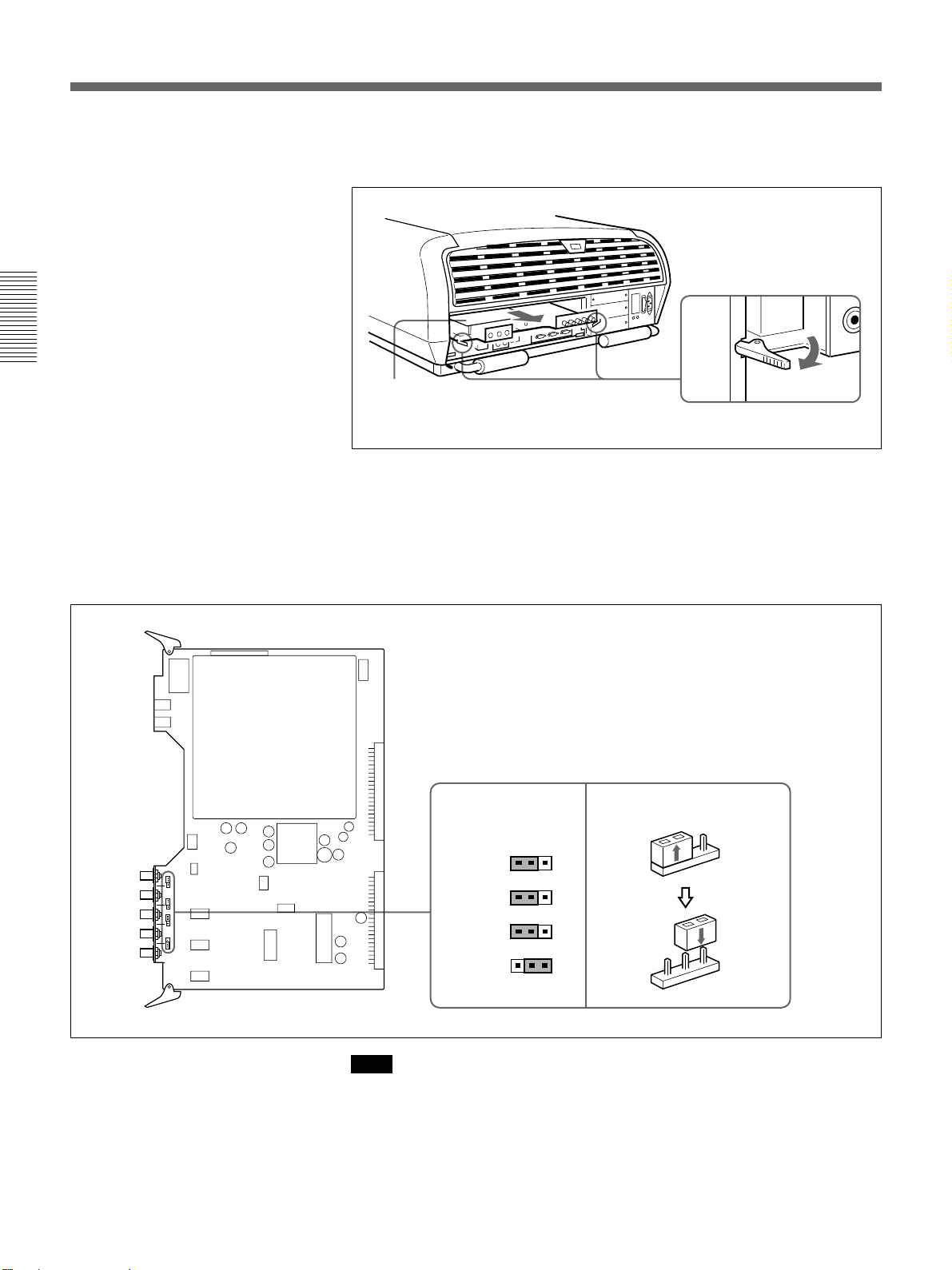
Switching the 75-ohm Terminate Connectors
(VPH-G90M/G90U only)
Depending on the connections of the computer and color monitor to the
projector, it may be necessary to switch the 75-ohm terminate connectors
on the BA board at the rear of the projector.
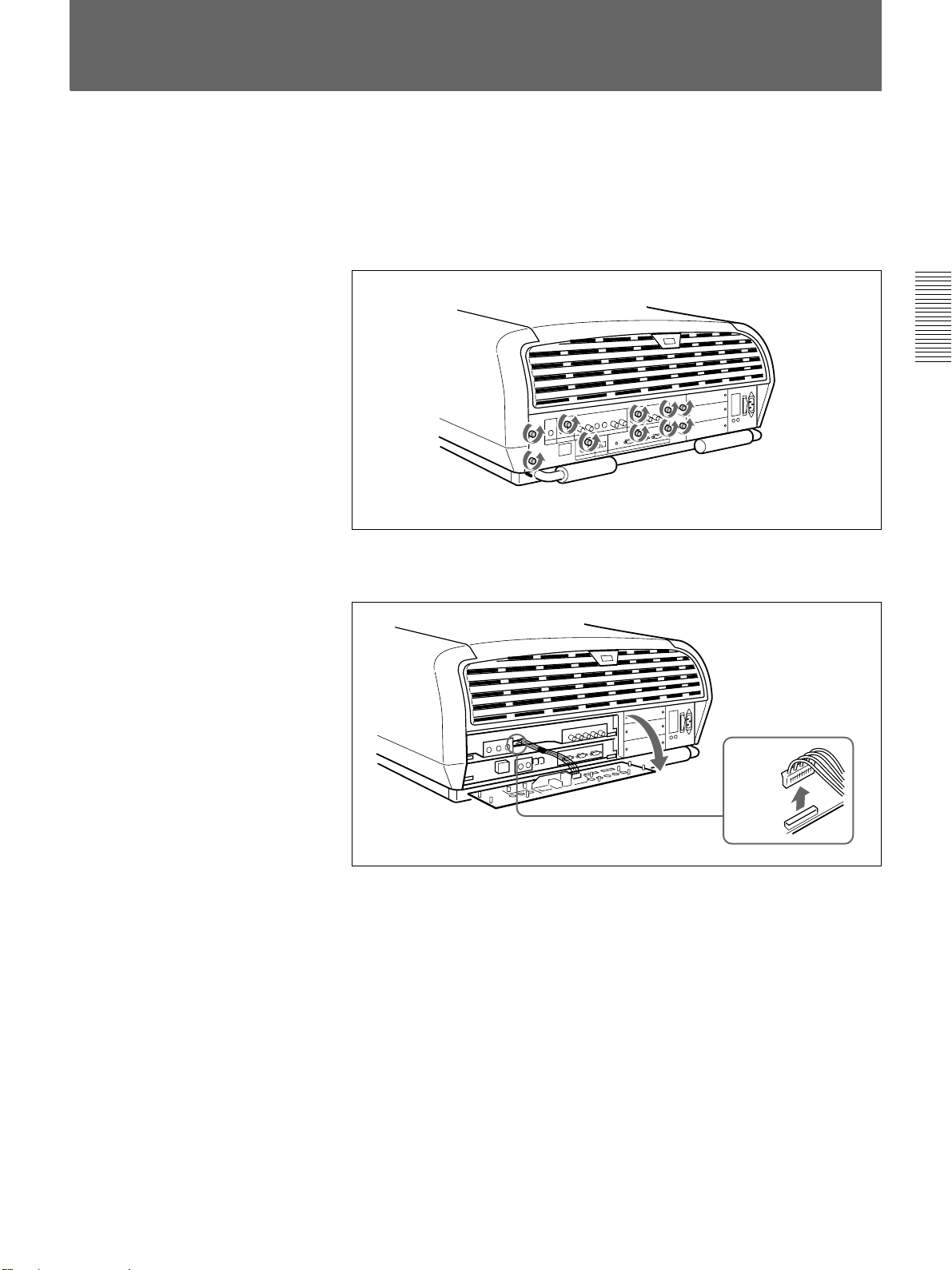
1 Loosen the ten screws at the rear of the projector to remove the
connector panel.
Connections
2 Disconnect the CN351 connector from the BA board.
CN351
(continued)
Connections 27 (GB)
Switching the 75-ohm Terminate Connectors
3 Open the card pullers and pull out the BA and BB boards carefully. Be
careful not to pull the wires.
Connections
BA and BB
boards
4 Switch the CN347, CN348 and CN349 connectors on the BA board.
75 Ω (pin position 3) is selected at the factory.
Set to OPEN (pin position 1) when the input signal is distributed into
other equipment using a branch connector and is terminated at 75 ohms
on that equipment.
BA board
Pin positions set at
the factory
321
CN347
321
CN348
321
CN349
321
CN350
Note
How to switch the connector
1
2
3
1
2
3
The pin position of the CN350 connector is set at the factory as illustrated.
Do not change the setting.
28 (GB) Connections
5 Perform the steps 1 to 3 above in the reverse order to replace the BA
and BB boards.
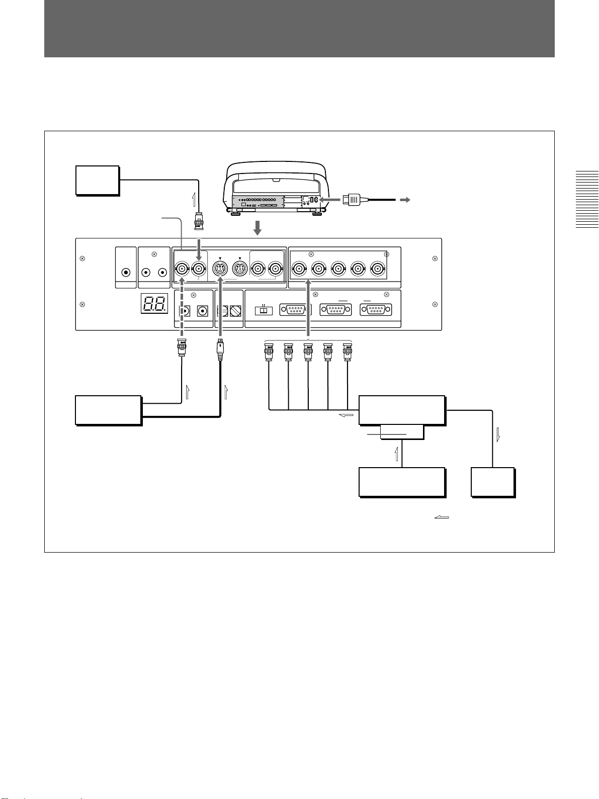
Connecting Directly to the Projector
This is an example to connect pieces of video equipment directly to a
single projector.
Use the IFU-1271/1271M Signal Interface Unit.
Rear
Color
to video input
monitor
*
VIDEO
OUT
IN
OUT
VIDEO
IN
PLUG IN POWER
CONTROL S
OUT
TRIGGER
IN
OUT
LINK
VIDEO IN S VIDEO
to video output
Video equipment
to S video output
* For the VPH-G90E model:
IFB-G90E Video Interface Board (optional).
OUT
IN
S VIDEO
VIDEO
DEVICE INDEX
IN
Y IN
RS-232C RS-422A
R
C IN
R
R-Y/PR
RS-232C/422A
G
AC IN
G B SYNC/HD VD
B-Y/PB
Y
INPUT A
IN OUTPJ COM
REMOTE
B
VD
SYNC/HD
IFB-12/12A
signal interface
board, etc.
AC power cord (supplied)
to a wall outlet
INPUT A
IFU-1271/1271M
Signal Interface Unit
to RGB input
to RGB output
Computer
Connections
to RGB output
to RGB input
Color
monitor
Signal flow
Setting up
•Set INPUT A in the SET SETTING 1 menu
(page 62 (GB)) to RGB.
•Select VIDEO or S VIDEO by pressing the INPUT SELECT keys on the
remote commander.
•Switch the 75-ohm terminate connectors on the BA board according to
the connections of the computer and color monitor.
For details, see “Switching the 75-ohm Terminate Connectors” on page 27 (GB).
Connections 29 (GB)
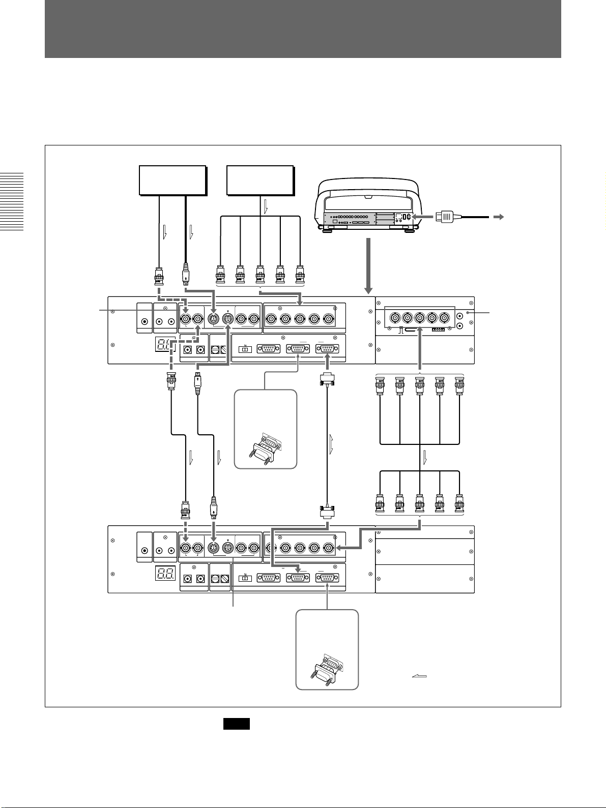
Connecting Multiple Projectors
This is an example to connect multiple projectors directly using the PJ
COM interface.
Install the optional IFB-12/12A Signal Interface Board to the INPUT B
section of the projector.
Video equipment Computer
Rear
AC power cord (supplied)
Connections
*
Second
projector
VIDEO IN
First
projector
VIDEO OUT
IN
TRIGGER
VIDEO IN
IN
TRIGGER
AC IN
to a wall outlet
S
VIDEO
R
G
B
SYNC/HD
VD
IN
INPUT A
R
OUT
IN
S VIDEO
VIDEO
DEVICE INDEX
Y IN
RS-232C RS-422A
C IN
IN
OUT
OUT
VIDEO
LINK
IN
OUT
PLUG IN POWER
CONTROL S
S VIDEO
OUT
Attach the
supplied
R-Y/PR
RS-232C/422A
REMOTE
PJ COM IN
G B SYNC/HD VD
B-Y/PB
Y
INPUT A
IN OUTPJ COM
PJ COM
OUT
R/P
R
B/PBSYNC/HD VD
R-Y/VIDEO
Y/Y B-Y/C
OUTIN
R
B
G
L
R
ON
123456
AUDIO
VD
(MONO)
IFB-12/12A
Signal Interface
Board (optional)
terminator.
SYNC/HD
5BNC cable
S VIDEO
IN
OUT
IN
S VIDEO
VIDEO
DEVICE INDEX
Y IN
RS-232C RS-422A
IN
OUT
OUT
VIDEO
LINK
IN
OUT
PLUG IN POWER
CONTROL S
C IN
RS-232C/422A
PJ COM IN
R
G B SYNC/HD VD
R-Y/PR
Y
REMOTE
B-Y/PB
INPUT A
IN OUT
PJ COM
INPUT A
PJ COM OUT
*
Attach the
supplied
terminator.
* For the VPH-G90E model:
IFB-G90E Video Interface Board (optional)
30 (GB) Connections
Signal flow
Note
Be sure to terminate the PJ COM IN or OUT connector not in use by
attaching the supplied terminator.
 Loading...