

Sony VPH-G70VRU, VPH-G70VRM Operating Instructions Manual
3-865-369-11 (2)
Multiscan Pr ojector
Operating Instructions
VPH-G70VRU
VPH-G70VRM
1998 by Sony Corporation
WARNING
To prevent fire or shock hazard, do not
expose the unit to rain or moisture.
To avoid electrical shock, do not open the
cabinet. Refer servicing to qualified
personnel only.
This symbol is intended to alert the user
to the presence of uninsulated
“dangerous voltage” within the product’s
enclosure that may be of sufficient
magnitude to constitute a risk of electric
shock to persons.
This symbol is intended to alert the user
to the presence of important operating
and maintenance (servicing) instructions
in the literature accompanying the
appliance.
For the customers in the USA
Note
This equipment has been tested and found to comply with
the limits for a Class A digital device, pursuant to Part 15 of
the FCC Rules. These limits are designed to provide
reasonable protection against harmful interference when the
equipment is operated in a commercial environment. This
equipment generates, uses, and can radiate radio frequency
energy and, if not installed and used in accordance with the
instruction manual, may cause harmful interference to radio
communications. Operation of this equipment in a residential
area is likely to cause harmful interference in which case the
user will be required to correct the interference at his own
expense.
For the customers in Canada
This Class A digital apparatus complies with Canadian ICES-
003.
For the customers in the United Kingdom
WARNING
THIS APPARATUS MUST BE EARTHED
IMPORTANT
This wires in this mains lead are coloured in accordance with
the following code:
Green-and-Yellow: Earth
Blue: Neutral
Brown: Live
As the colours of the wires in the mains lead of this
apparatus may not correspond with the coloured markings
identifying the terminals in your plug proceed as follows:
The wire which is coloured green-and-yellow must be
connected to the terminal in the plug which is marked by the
letter E or by the safety earth symbol Y or coloured green or
green-and-yellow.
The wire which is coloured blue must be connected to the
terminal which is marked with the letter N or coloured black.
The wire which is coloured brown must be connected to the
terminal which is marked with the letter L or coloured red.
Voor de klanten in Nederland
• Dit apparaat bevat een Li-ion batterij voor memory back-
up.
• De batterij voor memory back-up van het geheugen is
bevestigd op IC308 van plaat YB.
• Raadpleeg uw leverancier over de verwijdering van de
batterij op het moment dat u het apparaat bij einde
levensduur afdankt.
• Gooi de batterij niet weg, maar lever hem in als KCA.
• Bij dit product zijn batterijen geleverd.
Wanneer deze leeg zijn, moet u ze niet
weggooien maar inleveren als KCA.
The socket-outlet should be installed near the equipment
and be easily accessible.
Warning
You are cautioned that any changes or modifications not
expressly approved in this manual could void your authority
to operate this equipment.
2 Warning
AVERTISSEMENT
Afin d’éviter tout risque d’incendie et d’électrocution, ne
pas exposer l’appareil à la pluie ou à l’humidité.
Pour éviter tout risque de décharge électrique, ne pas
ouvrir le boîtier. Confiez l’entretien uniquement à un
personnel qualifié.
ACHTUNG
Um Feuergefahr und die Gefahr eines eiektrischen
Schlages zu vermeiden, darf das Gerät weder Regen
noch Feuchtigkeit ausgesetzt werden.
Im Geräteinneren befinden sich Teile, die unter
gefährlich hoher Spannung stehen. Das Gehäuse darf
nicht geöffnet werden. Überlassen Sie die Wartung nur
geschultem Fachpersonal.
Pour les utilisateurs au Canada
Cet appareil numérique de la classe A est conforme à la
norme NMB-003 du Canada.
La prise doit être près de l’appareil et facile d’accès.
Für Kunden in Deutschland
Dieses Produkt kann im kommerziellen und in begrenztem
Maße auch im industriellen Bereich eingesetzt werden. Dies
ist eine Einrichtung, welche die Funk-Entstörung nach
Klasse B besitzt.
Die Steckdose muß nahe bei diesem Gerät angebracht
und leicht zugänglich sein.
ADVERTENCIA
Para prevenir el riesgo de incendios o de electrocución,
no exponga la unidad a la lluvia nia la humedad.
Para evitar descargas eléctricas, no abra la unidad. En
caso de avería, solicite el servicio de personal
cualificado únicamente.
ATTENZIONE
Per evitare il pericolo di incendi o scosse elettriche, non
esporre l’apparecchio alla pioggia o all’umidità e non
aprirlo.
Per eventuali riparazioni, rivolgersi esclusivamente a
personale qualificato.
Warning 3

4 Warning
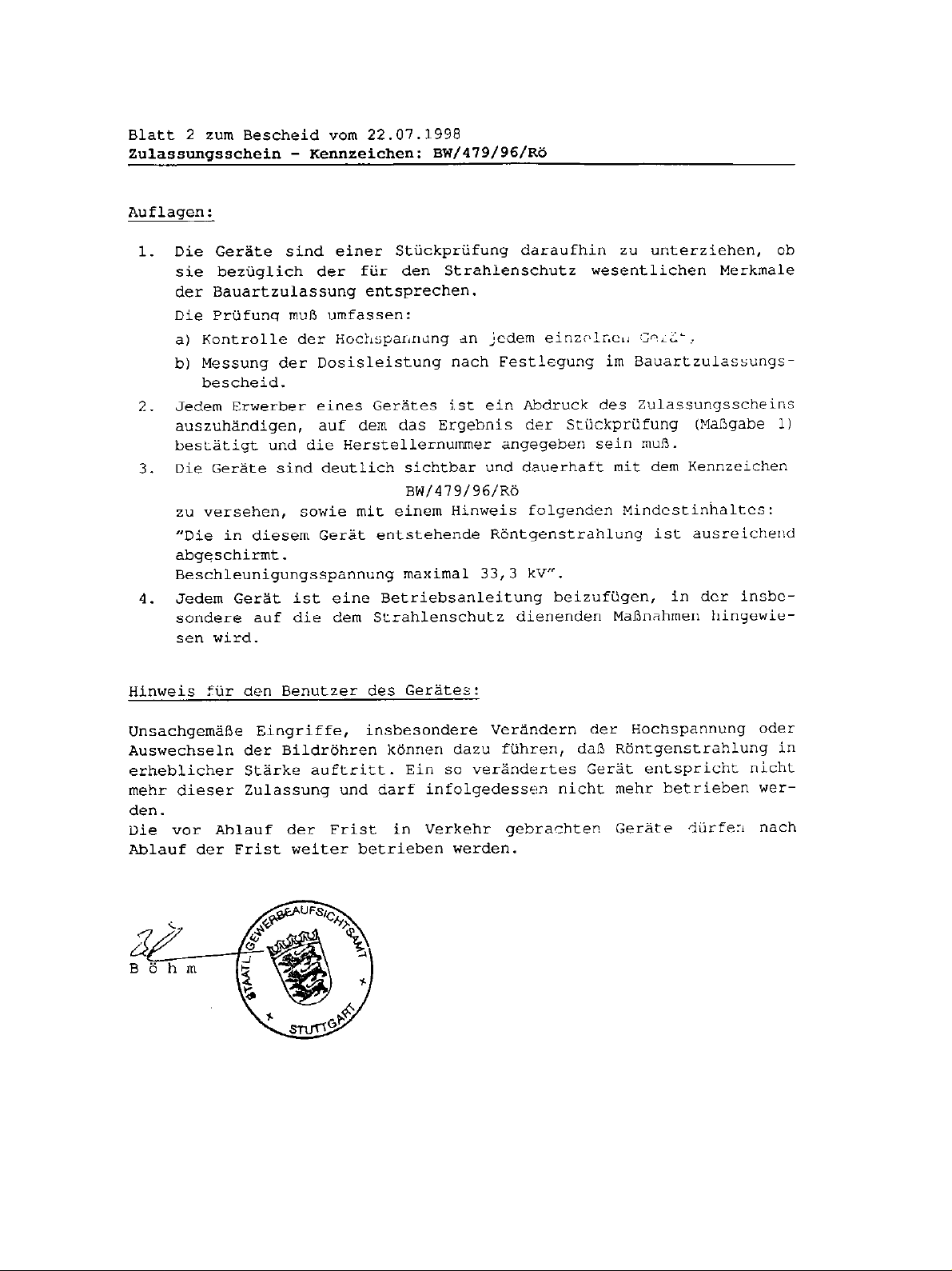
Die geforderte Stückprüfung hat ergeben, daß die gemessene Ortsdosis-Leistung unter dem
im Prüfungsschein Nr. 6.22-S 1227 der PTB genannten Wert von 0,2 µSv/h liegt.
Warning 5

6 Warning

Table of Contents
Overview
Projecting
Precautions ........................................................................ 8
Features............................................................................ 10
Location and Function of Controls................................ 12
Front ......................................................................................12
Rear .......................................................................................14
Remote Commander/Control Panel ......................................16
Projecting ......................................................................... 20
Adjusting the Picture ...................................................... 23
Adjusting the Size and Shift of the Picture ................... 24
SIZE Adjustment...................................................................24
SHIFT Adjustment ................................................................24
Blanking Adjustment.............................................................25
Centering Adjustment ..................................................... 26
Adjustments and settings using the menu
Using the Menu................................................................ 28
The INPUT SELECT Menu............................................... 30
The PIC CTRL (Picture Control) Menu........................... 31
The INPUT SETTING Menu ............................................. 33
The SET SETTING Menu ................................................. 36
The INPUT INFO (Information) Menu ............................. 39
The OPTION Menu ........................................................... 40
Installation/connection examples
Installation Examples...................................................... 41
Installation 1: Floor Installation Using Front Projection
Flat Screen .......................................................................42
Installation 2: Ceiling Installation Using Front Projection
Flat Screen .......................................................................43
Connection Examples ..................................................... 44
Connecting Directly to the Projector ....................................44
Using the Signal Interface Switcher......................................45
Maintenance / Other
Troubleshooting............................................................... 46
Specifications .................................................................. 47
Index ................................................................................. 50
Warning 7

Overview
Overview
Precautions
On safety
•Check that the operating voltage of your unit is identical with the voltage
of your local power supply. If voltage adaptation is required, consult with
qualified Sony personnel.
•Should any liquid or solid object fall into the cabinet, unplug the unit and
have it checked by qualified personnel before operating it further.
•Unplug the unit from the wall outlet or set the MAIN POWER switch to
OFF if it is not to be used for several days.
•To disconnect the cord, pull it out by the plug. Never pull the cord itself.
•The wall outlet should be near the unit and easily accessible.
•The unit is not disconnected from the AC power source (mains) as long
as it is connected to the wall outlet, even if the unit itself has been turned
off.
On installation
8 Overview
•When the projector is mounted on the ceiling, the Sony PSS-70 Projector
Suspension Support must be used for installation. Read the installation
manual of the PSS-70 carefully, since the ceiling should be reinforced for
safety.
•Allow adequate air circulation to prevent internal heat build-up. Do not
place the unit on surfaces (rugs, blankets, etc.) or near materials (curtains,
draperies) that may block the ventilation holes. Leave space of more than
30 cm (12 inches) between the wall and the projector. Be aware that room
heat rises to the ceiling; check that the temperature near the installation
location is not excessive.
•Do not install the unit in a location near heat sources such as radiators or
air ducts, or in a place subject to direct sunlight, excessive dust or
humidity, mechanical vibration or shock.
•To avoid moisture condensation, do not install the unit in a location
where the temperature may rise rapidly.

On illumination
On cleaning
•Fans are installed inside the projector to prevent internal heat build-up.
The fans produce a humming noise when the power is switched on, which
is normal. Should the noise sound abnormal, please consult qualified
Sony personnel.
Overview
•To obtain the best picture, the front of the screen should not be exposed
to direct lighting or sunlight.
•Ceiling-mounted spot lighting is recommended. Use a cover over
fluorescent lamps to avoid lowering the contrast ratio.
•Cover any windows that face the screen with opaque draperies.
•It is desirable to install the projector in a room where floor and walls are
not of light-reflecting material. If the floor and walls are of reflecting
material, it is recommended that the carpet and wall paper be changed to
a dark color.
•To keep the cabinet looking new, periodically clean it with a soft cloth.
Stubborn stains may be removed with a cloth lightly dampened with a
mild detergent solution. Never use strong solvents, such as thinner,
benzene, or abrasive cleansers, since these will damage the cabinet.
•Avoid touching the lens. To remove dust on the lens, use a soft dry cloth.
Do not use a damp cloth, detergent solution, or thinner.
CRT burns
On repacking
When a static picture of a VCR or a computer is displayed for more than
about an hour, a CRT burn may result. This means that an after-image
impression of the static picture remains on the screen even after the picture
has changed. If it is necessary to display the same static picture for more
than an hour, we recommend that you set the CONTR (contrast) control to
the lowest setting.
Also, when a picture of different size is displayed beyond a certain length
of time, an after-image impression of the frame of the smaller picture may
be burnt on the screen (such as displaying a 16:9 wide size picture on a 4:3
screen). To avoid this, we recommend that you use the same picture size
when possible. However, if it is necessary to use a different picture size,
set the CONTR (contrast) control and the BRT (brightness) control of the
smaller picture to the lowest setting possible. This will minimize the risk
of creating an after-image impression.
If the CRT burns, it must be replaced. In this case, refer to the warranty
provided with this unit. Consult your Sony dealer or Qualified Service
Personnel.
Save the original shipping carton and packing material; they will come in
handy if you ever have to ship your unit. For maximum protection, repack
your unit as it was originally packed at the factory.
Overview 9

Features
Multiscan projector
Overview
High resolution and brightness
High contrast
This projector accepts and automatically detects horizontal scanning
frequencies between 15 kHz and 110 kHz and vertical scanning
frequencies between 38 Hz and 150 Hz.
In addition to high-resolution pictures from computers, you can also
project pictures from teletext decoders, VCRs and video cameras.
A newly developed 8-inch electromagnetic focus CRT, a hybrid Sony
HACC (High-resolution Aspherical and Color Corrected) lens and a wide-
range cathode/G1 dual-drive video output circuit are incorporated in the
projector to provide a sharp and bright high-quality picture with the high
resolution of 1700 × 1200 pixels and the high light output of 200 lumen.
The adoption of the optical coupling technologies, double-focus lens
system and an anti-reflection coating gives a fine-detail and sharp picture
with improved contrast in corners and screen center.
Easy operation — remote commander, on-screen display
Adjustments such as input selection, picture control and centering
adjustment can be remotely controlled from both the front and rear of the
projector with the supplied remote commander. You can also use the
commander as a wired remote control by connecting it to the projector
with the supplied remote control cable.
Compatible with various color systems
NTSC, PAL, SECAM, NTSC4.431) or PAL-M color system can be selected
automatically or manually.
Flexible setup
You can project a 60- to 300-inch picture (120-inch standard) with this
projector. The projector can be set up on the floor or ceiling, for front or
rear projection to suit the installation location, surrounding illumination,
usage, etc.
..........................................................................................................................................................................................................
1) NTSC4.43 is the color system used when playing back a video recorded on NTSC on a NTSC4.43 system VCR.
10 Overview

Illuminated control panel/remote commander keys
The key names on the remote commander and the control panel of the
projector can be illuminated for easy access in a dark place by pressing the
LIGHT button.
Overview
Overview 11
Overview
Location and Function of Controls
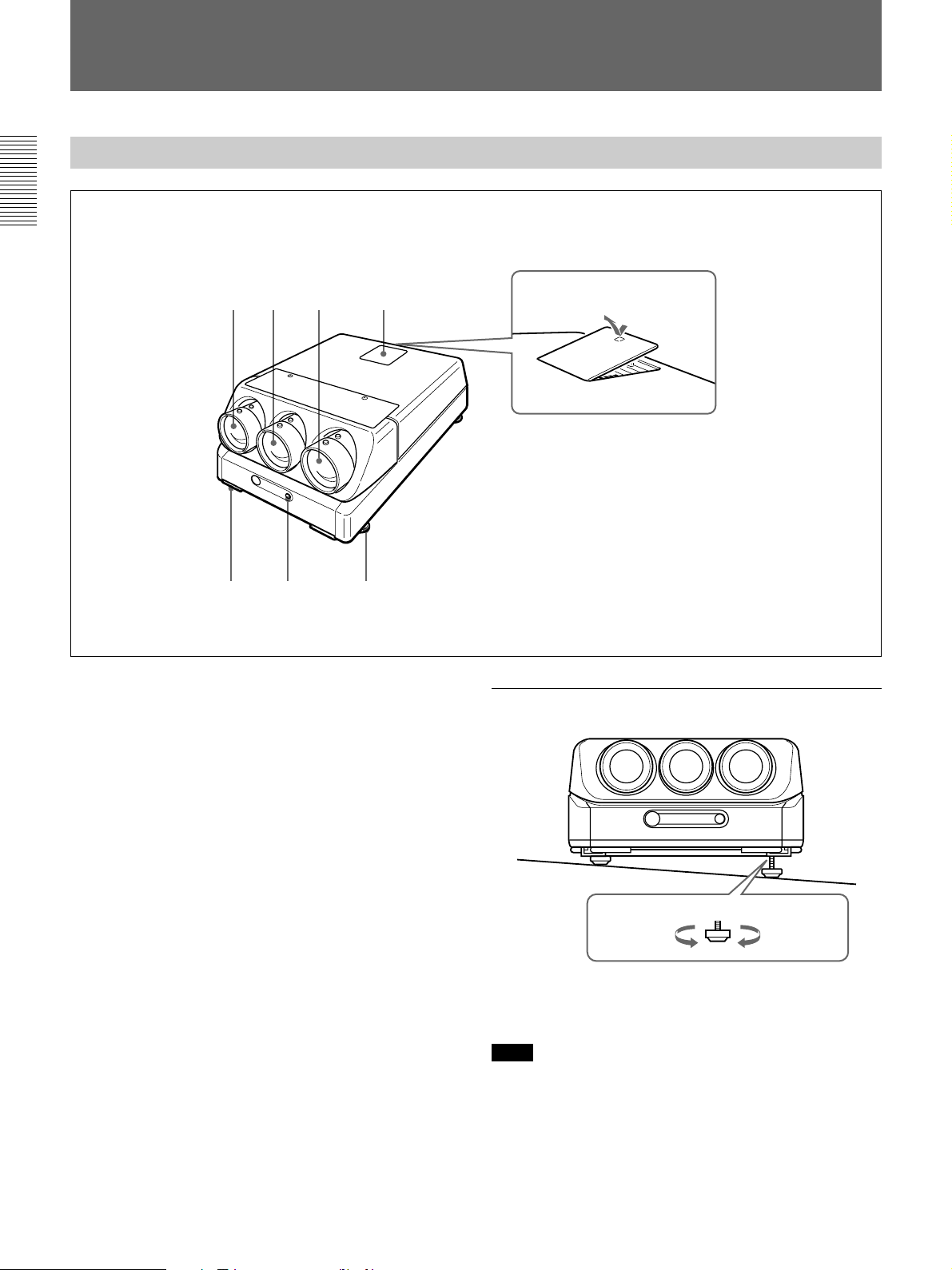
Front
1 Blue lens
2 Green lens
23 4
1
56 7
How to open the control
panel cover
How to use the adjusters
3 Red lens
4 Control panel cover
The control keys are inside the cover.
The locations and functions of the control keys are the
same as those of the remote commander.
For details, see “Remote Commander/Control Panel” on
page 16.
5 Handles
Used for carrying the projector. The handles are
located on the front, rear, left and right sides.
6 Front remote control detector
7 Adjusters
Used to keep the projector level if it is installed on an
uneven surface (equipped with four adjusters).
To lower
the projector
To raise
the projector
While lifting the projector, turn the adjusters to adjust
the height so that the projector becomes level.
Note
Be careful not to let the projector down on your
fingers.
12 Overview
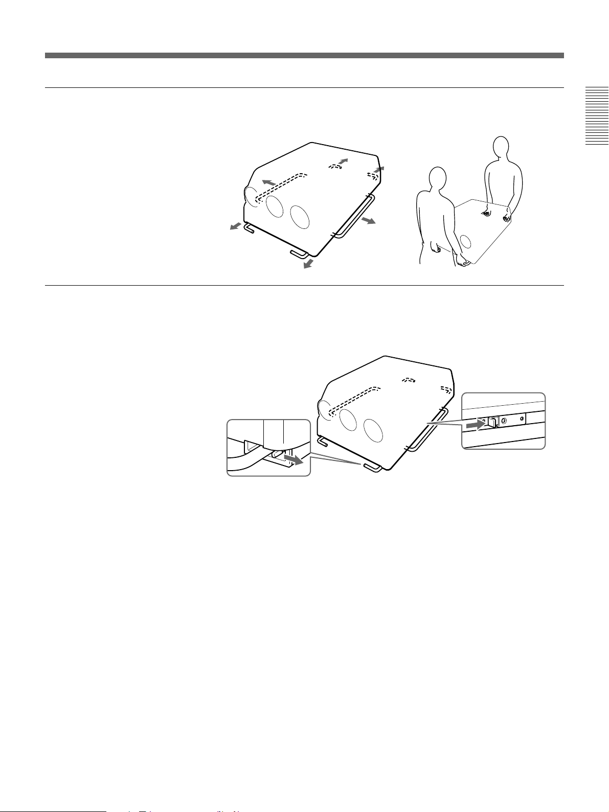
Using the handles
Putting away the handles
Pull out the front and rear handles or the side handles.
Overview
Push the handle release lever under each handle. The handle is
automatically retracted.
Overview 13

Location and Function of Controls
Rear
Overview
12 3 4
REMOTE
PLUG IN
POWER
RS-422A
INDEX
INPUT A
R
R-Y
P
G
Y
B
B-Y
P
SYNC
HD
VD
CONTROL S
TRIGGER
R
B
ABL LINK
IN
OUT
IN
OUT
56 7 8 9
1 Signal interface board attachment part (INPUT
B)
Attach an optional signal interface board IFB-40, IFB1000, etc.
2 INPUT A connectors (BNC type)
R/R-Y/P
connectors: Connect to the outputs of a computer or a
3 TRIGGER connector (minijack)
When the projector is turned on, 12 V is output and
when it is turned off, 0 V is output. However, the
connector is not used as the power source since the
power is not output.
4 RS-422A REMOTE connector (D-sub 9-pin)
Used to expand the system connections using the RS422A interface.
Before using the connector, loosen the two screws to
remove the cap.
R, G/Y, B/B-Y/PB, SYNC/HD, VD
video camera. According to the connected
equipment, the RGB (R, G, B), component (R-Y,
G, B-Y) or HDTV (P
R, Y, PB) signal is selected.
IR
POWER
STANDBY
!º
!¡
!™
!£
MAIN POWER
ONOFF
AC IN
100~120V 15A 250V
200V~240V T6.3A 250V
5 ABL (Automatic Brightness Limiter) LINK IN/
OUT jacks (minijack)
When connecting multiple projectors, connects the
ABL LINK OUT jack to the ABL LINK IN jack on
another projector. You can synchronize the brightness
limiting point among the projectors, allowing to make
the whole screen brightness uniform.
6 CONTROL S jacks
IN/PLUG IN POWER (5 V) jack (stereo minijack):
Connects to the CONTROL S OUT jack of other
Sony equipment. Also connects to the CONTROL
S OUT jack of the supplied remote commander
with the supplied remote control cable (stereo
cable) to be used as a wired remote control. In this
case, this jack supplys 5 V to the remote
commander as power source.
OUT jack (stereo minijack): Connects to the
CONTROL S IN jack of other Sony equipment.
Note
When using this jack, the remote control detector on
the projector does not function.
14 Overview

7 INDEX NO. switches
When multiple projectors are connected, set the index
number of each projector.
To display the index number on the screen, press the
NORMAL key, and the ENTER key on the remote
commander.
Note
If you set the index number to “00,” the projector does
not operate.
8 AC IN socket
Connect the supplied AC power cord.
9 MAIN POWER switch
0 Error code window
An error code lights up when an operational error
occurs.
!¡ POWER indicator
Lights in green when the power is turned on.
Overview
!™ u STANDBY indicator
Lights in orange when the MAIN POWER switch is
turned on. Once in the standby mode, you can turn the
projector on and off with the remote commander.
!£ Rear remote control detector
Overview 15
Location and Function of Controls
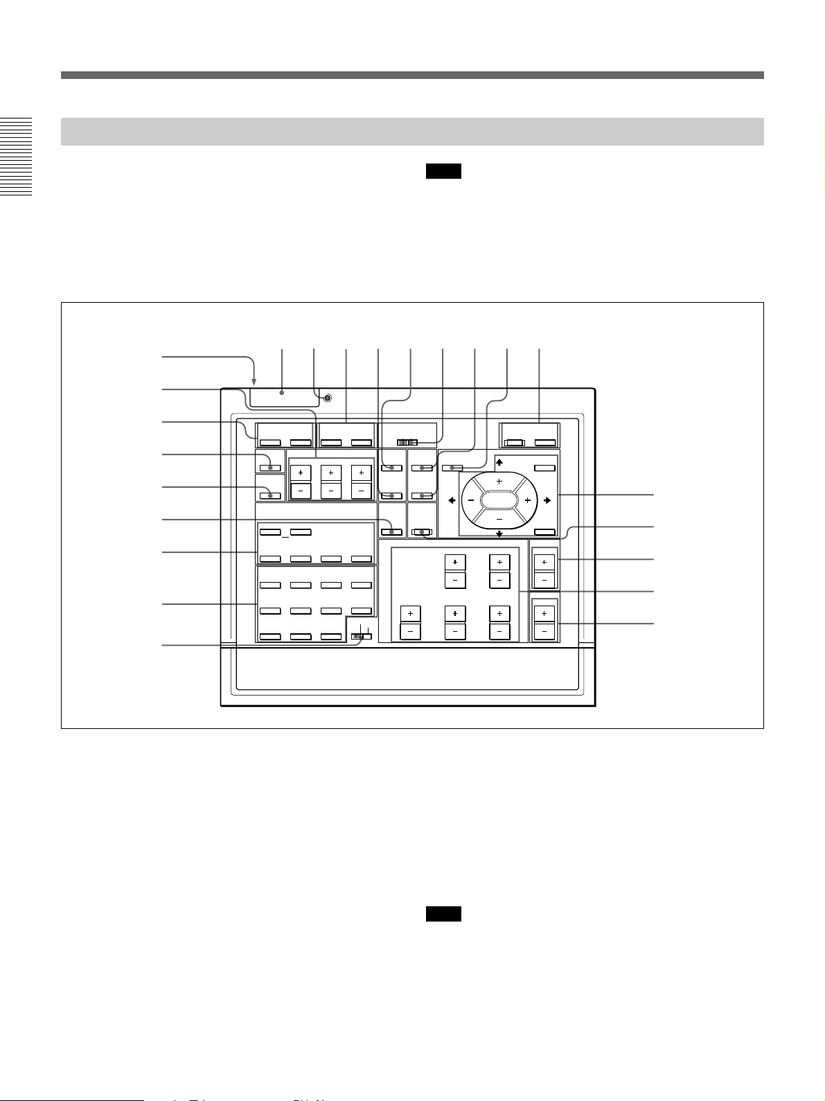
Remote Commander/Control Panel
The locations and functions of the keys on the remote
commander are the same as those on the control panel
Overview
of the projector. (Only the remote commander is
equipped with the transmission indicator and the
COMMAND ON/OFF switch.)
The remote commander may be used as a wired or
wireless remote control.
1
@£
@™
@¡
@º
!ª
!•
!¶
!§
LIGHT
MUTING
PIC
AUDIO OFF
LCD LENS CONTROL
ZOOM
NORMAL
PATTERN
INPUT SELECT
VIDEO SELECT
B
A D
SWITCHER/INDEX
1
5
67
9
0(ALL)
!∞
234
STATUS
SHIFT
VIDEO/S VIDEO
C
SECOND
ON
FOCUS
423
8
SWITCHER
INDEX
COMMAND
RGB
SIZE
SHIFT
BLKG
Note
The VOLUME +/– !¢, INPUT SELECT VIDEO,
SELECT VIDEO/S VIDEO, C and D !¶, AUDIO
MUTING @¡ and LCD LENS CONTROL @™ keys do
not function with this projector.
6
7895
POWER
ON
OFF
CENT
R
MEMORY
B
RESET
PICTURE CONTROL
BRIGHT
SHARP VOLUME
CONTR
HUE COLOR
OFF
ON
MENU
ENTER
POSITION
!º
!¡
!™
!£
!¢
1 LIGHT button
Illuminates the key indicators.
The key indicators turn off if you press the LIGHT
button again.
If you do not press any key for more than 30 seconds,
the indicators also turn off automatically.
If the COMMAND 6 switch on the remote
commander is set to OFF, only the COMMAND
switch is illuminated.
When the remote commander is connected to the
CONTROL S IN/PLUG IN POWER jack of the
projector via the remote control cable, the power is
supplied to the remote commander from the projector.
16 Overview
2 Transmission indicator (only for the remote
commander)
Lights each time you press a key. If it does not light,
replace the batteries with new ones.
3 STATUS ON/OFF key
Press OFF to eliminate the on-screen display.
Press ON to restore the on-screen display.
Note
The menus and warning messages appear even if the
OFF key is pressed.
 Loading...