

Sony VPH-D50Q,VPH-D50QM Installation Manual

VPH-D50Q/VPH-D50QM
3-858-837-14 (1)
Multiscan
Projector
Installation Manual for Dealers
Before operating the unit, please read this manual
thoroughly and retain it for future reference.
Manuel d’installation destiné aux
revendeurs
Avant de mettre cet appareil en exploitation, veuillez lire
attentivement ce manuel et le ranger en lieu sûr aux fins
de consultation ultérieure.
Manual de instalación para
proveedores
Antes de utilizar la unidad, lea este manual en su
totalidad y consérvelo para realizar consultas.
CAUTION
THIS INSTALLATION MANUAL IS FOR USE BY QUALIFIED PERSONNEL
ONLY.
IMPORTANT
CE MANUEL D’INSTALLATION EST DESTINÉ AUX PROFESSIONNELS
SEULEMENT.
IMPORTANTE
ESTE MANUAL DE INSTALACIÓN ES PARA SER USADO POR PERSONAL
CUALIFICADO SOLAMENTE.
VPH-D50Q
VPH-D50QM
©1996 by Sony Corporation
English
Table of Contents
Installation
Connections
Before Adjustment
Installation Procedures .................................................................... 4(EN)
Installation Diagrams.......................................................................5(EN)
Necessary Clearance for Installation and Maintenance ........... 5(EN)
Using the Handles to Carry the Projector ................................ 8(EN)
Floor Installation Using Front Projection Flat Screen ............. 9(EN)
Ceiling Installation Using Front Projection Flat Screen ........ 11(EN)
Floor Installation Using Rear Projection Flat Screen ............ 13(EN)
Notes on Screen...................................................................... 15(EN)
Modifying Parts .............................................................................. 17(EN)
Removing the Upper Cover ................................................... 17(EN)
Changing the Polarity............................................................. 17(EN)
Adjusting the CRT Conversion Angle.................................... 20(EN)
Location and Function of Connectors .......................................... 22(EN)
Switching the 75-ohm Terminate Connectors .............................. 24(EN)
Connecting Directly to the Projector ............................................ 26(EN)
Using the Signal Interface Switcher.............................................. 27(EN)
Connecting Multiple Projectors .................................................... 31(EN)
Using the Linked ABL Function ............................................ 34(EN)
Adjustment Procedures.................................................................. 36(EN)
For Remote Control........................................................................ 37(EN)
Preparation ............................................................................. 37(EN)
Keys on the Remote Control .................................................. 40(EN)
Using the Menu ............................................................................... 43(EN)
Basic Menu Operation............................................................ 43(EN)
The INPUT SELECT Menu................................................... 44(EN)
The PIC CTRL (Picture Control) Menu................................. 45(EN)
The INPUT SETTING Menu................................................ 47(EN)
The SET SETTING Menu ..................................................... 50(EN)
The INPUT INFO (Information) Menu ................................. 52(EN)
The SERVICE SETTING Menu ............................................ 54(EN)
The SET INFO (Information) Menu ...................................... 55(EN)
The ABL (Automatic Brightness Limiter) LINK Menu ........ 56(EN)
The OPTION Menu................................................................ 57(EN)
Test Patterns .................................................................................... 58(EN)
Test Patterns ........................................................................... 58(EN)
Test Patterns in Each Mode .................................................... 60(EN)
2 (EN)
Adjustment
Adjusting the Focus ........................................................................ 61(EN)
Focus Adjustment Procedure .................................................. 61(EN)
Adjusting the Green Focus ..................................................... 62(EN)
Adjusting the Red and Blue Focus ......................................... 66(EN)
Adjusting the Registration............................................................. 68(EN)
Procedure................................................................................ 68(EN)
Preparation ............................................................................. 69(EN)
Keys for Adjusting.................................................................. 70(EN)
Adjusting the Green Registration ........................................... 71(EN)
Adjusting the Red Registration .............................................. 80(EN)
Adjusting the Blue Registration ............................................. 89(EN)
Saving the Standard Registration Data................................... 90(EN)
Fine Adjustment for Each Input Signal........................................ 91(EN)
Adjusting the Video Input Signal ........................................... 91(EN)
Adjusting the RGB Input Signal ............................................ 93(EN)
Adjusting the White Balance.................................................. 96(EN)
Saving the Adjustment Data .......................................................... 98(EN)
Resetting the Data......................................................................... 100(EN)
Resetting the Data ................................................................ 101(EN)
Protecting the Setting ................................................................... 102(EN)
Adjusting the Picture Quality...................................................... 103(EN)
Others
Changing the Initialization Period.............................................. 104(EN)
About Error Codes ....................................................................... 105(EN)
List of the Projection Distance by Angle of Optical Axis .......... 106(EN)
Index .............................................................................................. 111(EN)
3 (EN)

Installation Procedures
By default, this projector is adjusted for 120-inch front projection on the
floor/desk. If you install the projector in other conditions, you have to
change some settings. Therefore, installation procedures depend on the
screen size or type, and installation method.
Installation
1 V erify the conditions of installa tion, such as angle of optical axis,
projection distance, height of the projector and screen.
.
2 Chang e the polar ity accor ding to the pr ojection pa tter ns. (page 17 (EN))
.
3 Install the pr ojector and scr een. (page 9 (EN))
.
4 Reset the r egistr ation da ta to f actor y setting. (page 101 (EN))
.
5 Adjust the CR T conversion angle . (pag e 20 (EN))
.
6 Adjust the lens f ocus and f lapping of the lens. (page 62 (EN))
.
7 Adjust the r e gistrations. (page 68 (EN))
.
8 Connect other equipment. (page 26 (EN))
.
9 Adjust eac h input signal. (pages 91 (EN) to 97 (EN))
• Fine adjustment for the registrations. (pages 91 (EN) and 94 (EN))
• Adjust the size or shift of the picture. (pages 92 (EN), 94 (EN) and
95 (EN))
• Adjust the blanking. (pages 93 (EN) and 95 (EN))
4 (EN) Installation
Installation Diagrams
Installation Diagrams
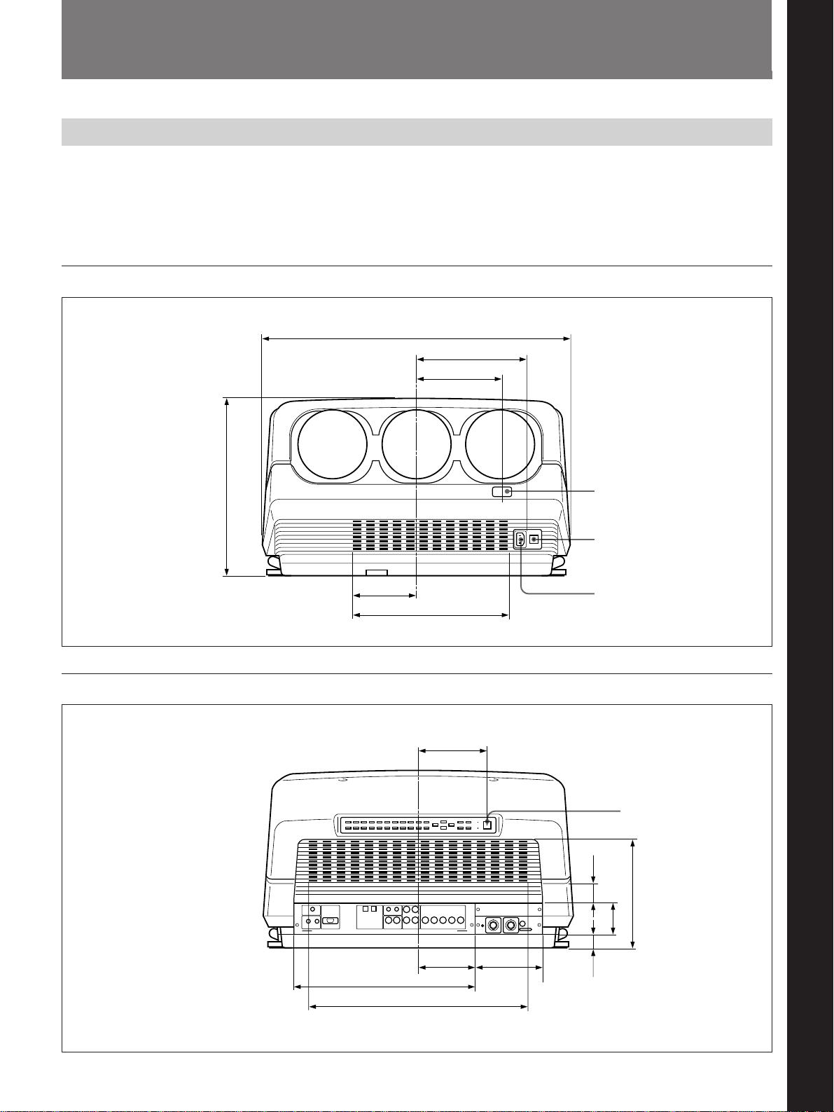
Necessary Clearance for Installation and Maintenance
Make sure to provide enough room for maintenance service. Install the
projector, making reference to the dimensions below.
There should be a space of at least 30 cm (1
ventilation holes. Never block the holes with any material.
Front
603 (23 3/4)
214 (8 7/16)
164.7 (6 15/32)
32)
/
19
3
/16 inches) around the
Remote control detector
Installation
Installation
Rear
345 (13
125 (4 29/32)
302 (11 7/8) (Ventilation holes)
133 (5 1/4)
110 (4 11/32) 128 (5 1/32)
350 (13 25/32)
424 (16 11/16) (Ventilation holes)
MAIN POWER switch
AC IN socket
Error code window/
Remote control detector
/32)
13
27
35.5
)
/16
1
(1
(1
59.4
)
32
/
11
(2
/16)
15
125.8 (4
Unit: mm (inches)
Unit: mm (inches)
Installation 5 (EN)
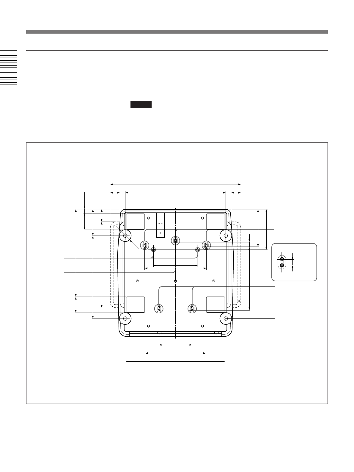
Installation Diagrams
Bottom
Installation
The standard hole for installation on the bottom surface is useful for
reference when measuring for installation. There are seven holes on the
bottom surface of the projector. For ceiling installation using the optional
PSS-70 Projector Suspension Support, use five holes to attach the PSS-70.
The other two holes are spare ones.
Notes
• Use only the M8 meter screws of 10 mm (13/
long for the attachment holes for the PSS-70.
• When attaching the PSS-70, use the M8 meter screws of 20 mm (25/32 inches)
supplied with the PSS-70.
inches) to 30 mm (1 3/
32
inches)
16
Receptacles for
the projections
of the PSS-70
Standard hole
for installation
)
/32
29
22.8 (
/32)
9
83 (3
/32)
1
457.8 (18
/32)
9
83 (3
/16)
7
137.8 (5
/4)
3
/8)
1
451 (17
435 (17
/16)
9
64.8 (2
50 (1 31/32)
Ø 60
679 (26 23/32)
524 (20 5/8)
230 (9 1/16)
174 (6 27/32)
318 (12 17/32)
515 (20 9/32)
322 (12 11/16)
50 (1 31/32)
/32)
/32)
21
11
194.6
(7
)
32
/
31
211.8 (8
25 (
32)
/
1
330.7 (13
Holes for attaching
the PSS-70/spare
holes (M8 meter
screws, 20 mm
(25/32 inches))
Spare holes
/16)
9
Holes for attaching
the PSS-70
Holes for attaching the
PSS-70/Spare holes
Handle
Adjuster
14 (
6 (EN) Installation
Unit: mm (inches)
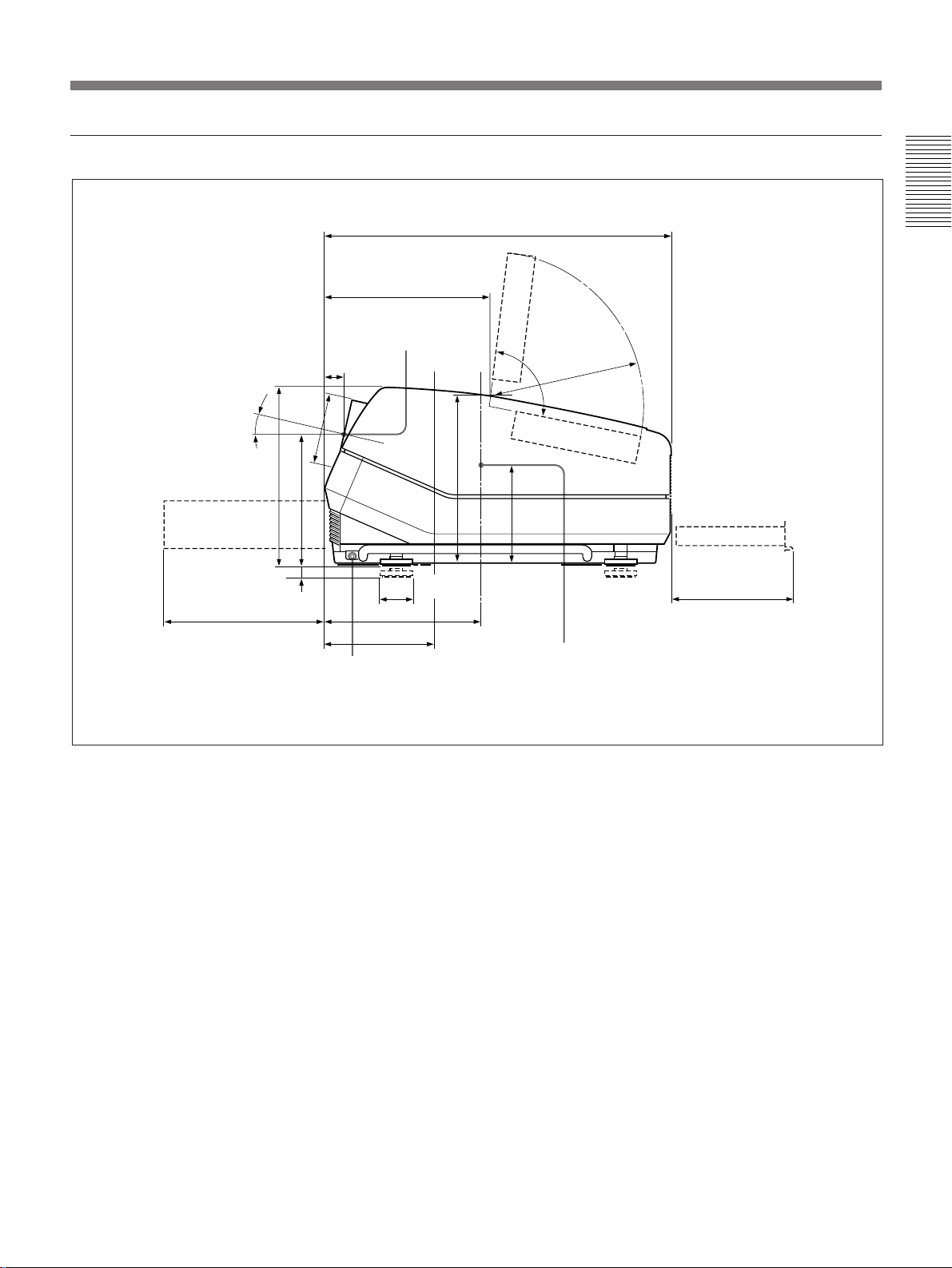
Side
Power supply/
High voltage
circuit block
311.2 (12 1/4)
38
(11/2)
)
32
/
12.5°
∅137
/32)
19
345 (13
254 (10)
/32)
20
25
(
13
(5
Handle release lever
319 (12 5/8)
Center of the
green lens
∅60 (2 3/8)
301.7 (11 7/8)
169.6 (6 11/16)
Location of the
standard hole
for installation
671 (26 13/32)
329 (13)
Deflection
board
95°
R298 (11
)
16
/
1
154
(6
Center of the gravity
of the projector
)
23
32
/
Adjuster
Installation
Signal board
235.7 (9 9/32)
Unit: mm (inches)
Installation 7 (EN)
Installation Diagrams
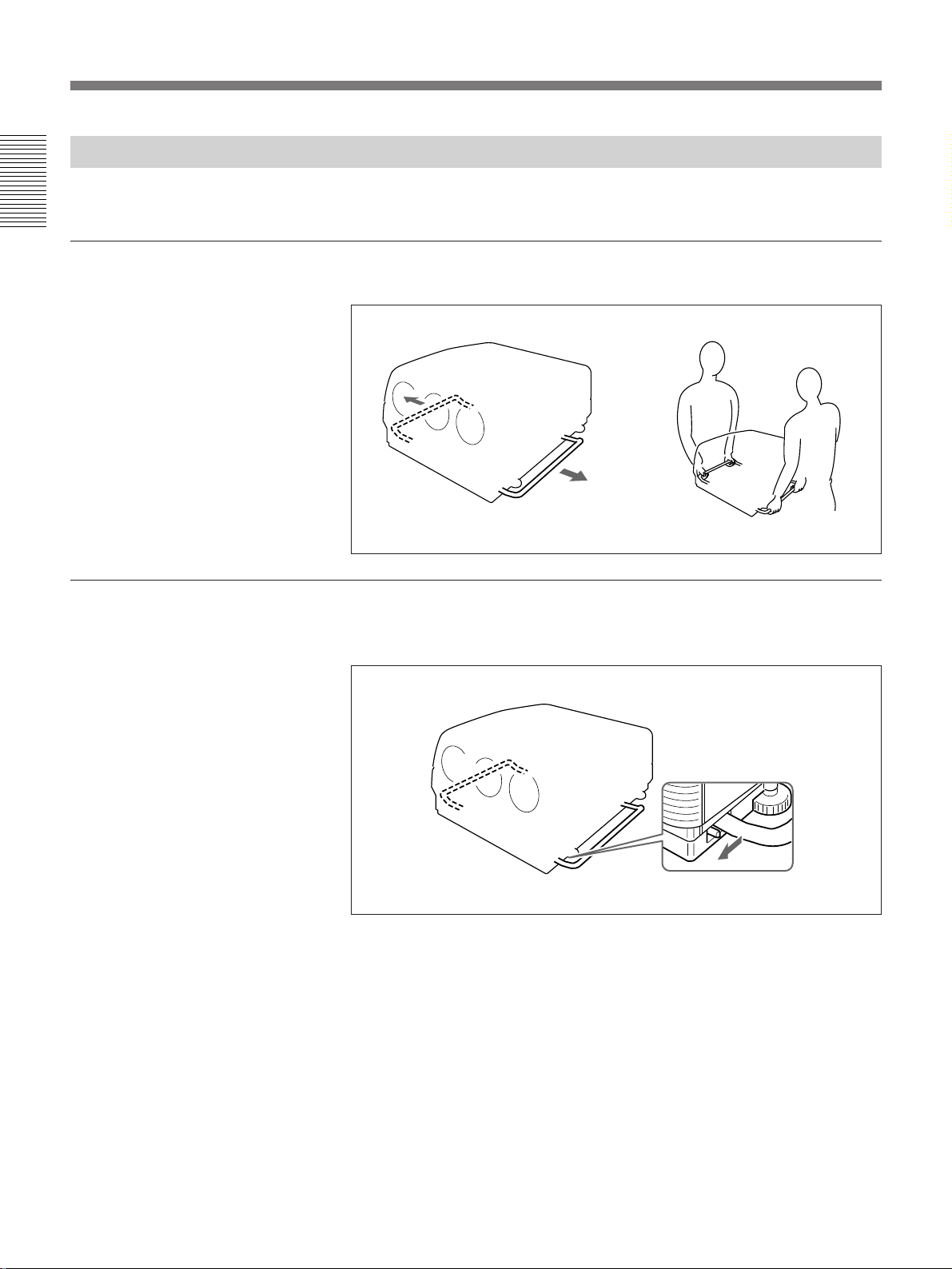
Using the Handles to Carry the Projector
Installation
Using the handles
You can carry the projector by using the side (right and left) handles.
Pull out the side handles.
Putting away the handles
Pull the handle release lever under each handle towards you. The handle is
automatically retracted.
8 (EN) Installation
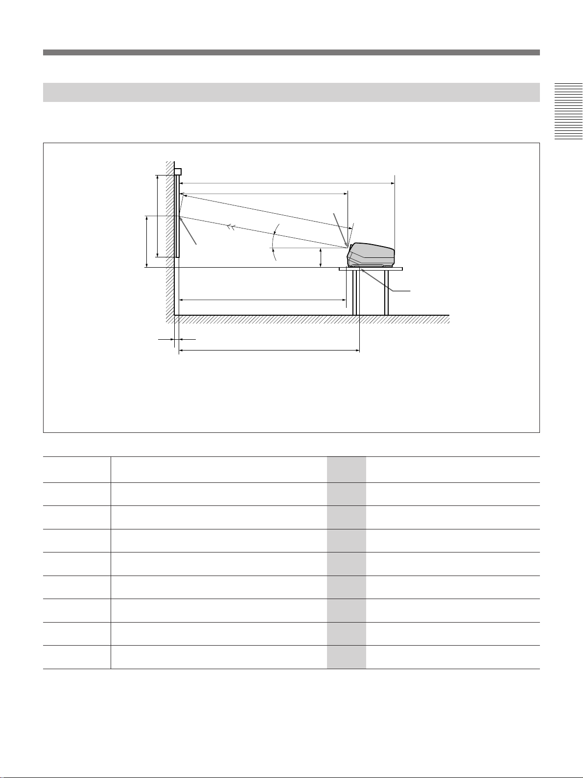
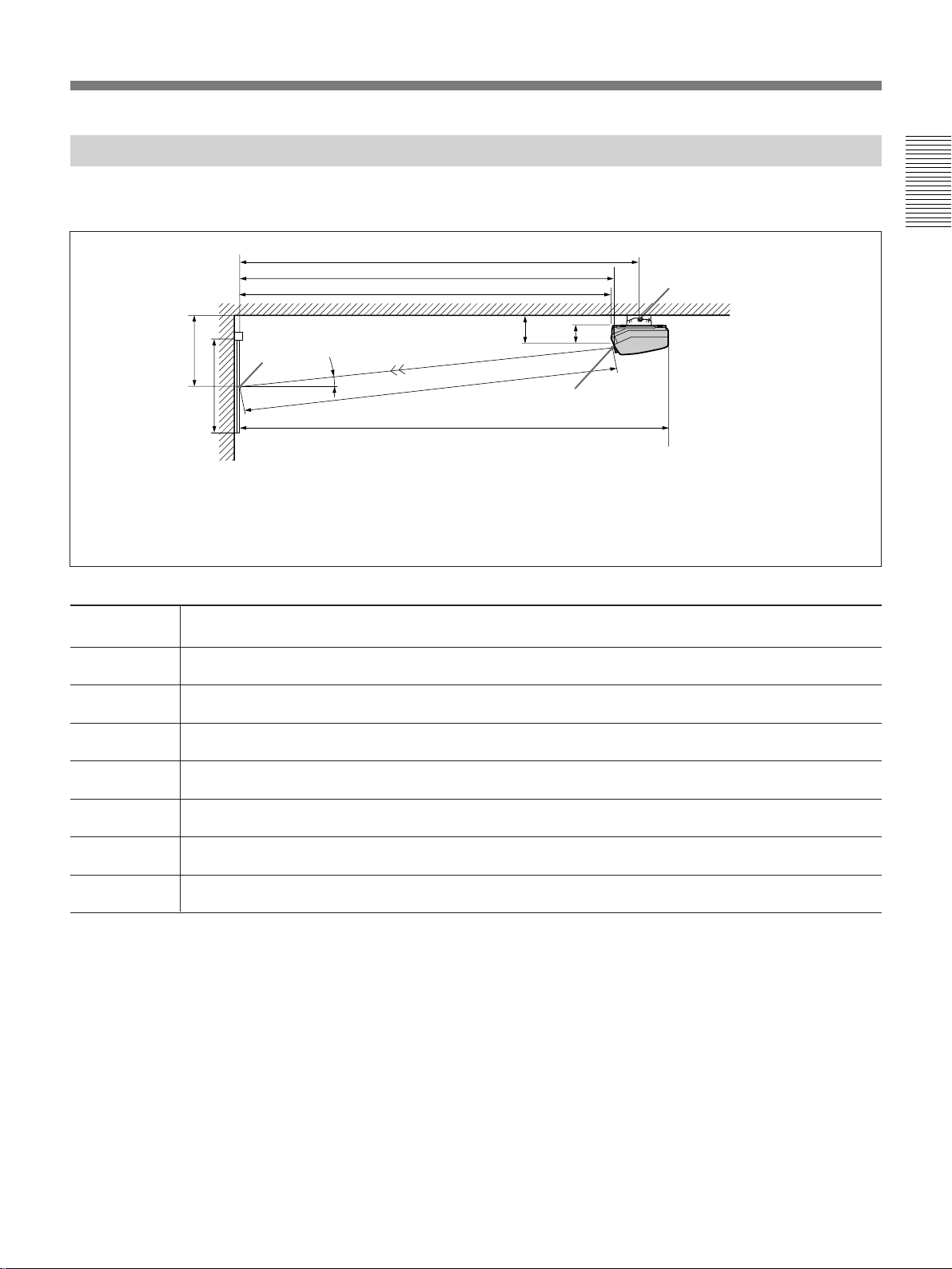
Floor Installation Using Front Projection Flat Screen
Be sure that the projector is level to the floor.
Wall
G
A
E
D
Center of the
green lens
Installation
13.5˚
254 (10 )
H
F
B: ±5%
Other measurements: 0% to +5%
The distances in gray are the factory preset settings. Unit:mm (inches)
Standard hole
for installation
Floor
Screen size
B
Center of the screen
C
B: Difference in height between the projector’s bottom surface and the center of the screen
E: Horizontal distance between the center of the screen and the center of the green lens
F: Horizontal distance between the center of the screen and the standard hole for installation
Tolerances
60 70 80 90 100 120 150 180 200 250
(inches)
A (Vsize) 914 1067 1219 1372 1524 1829 2286 2743 3048 3810
(36) (42) (48) (54) (60) (72) (90) (108) (120) (150)
B (Hcent) 710 777 845 912 980 1114 1320 1526 1662 2005
(28) (30 5/8) (33 3/8) (36) (38 5/8) (43 7/8) (52) (60 1/8) (65 1/2) (79)
C (Width)
28a)32
b)
32
c)
(1 1/8) (1 5/16) (1 5/16)
D (TD) 1956 2240 2529 2816 3102 3673 4551 5425 6012 7466
(77) (88 1/4) (99 5/8) (110 7/8) (122 1/4) (144 5/8) (179 1/4) (213 5/8) (236 3/4) (294)
E (Xlens) 1902 2179 2459 2738 3016 3571 4424 5274 5844 7257
(74 7/8) (85 7/8) (96 7/8) (107 7/8) (118 7/8) (140 5/8) (174 1/4) (207 5/8) (230 1/8) (285 3/4)
F (Lhole) 2033 2310 2591 2869 3148 3703 4556 5405 5976 7389
(80 1/8) (91) (102) (113) (124) (145 7/8) (179 3/8) (212 7/8) (235 3/8) (291)
G (Lmax) 2535 2812 3092 3371 3649 4204 5057 5907 6477 7890
(99 7/8) (110 3/4) (121 3/4) (132 3/4) (143 3/4) (165 5/8) (199 1/8) (232 5/8) (255 1/8) (310 3/4)
H (Lfront) 1864 2141 2421 2700 2978 3533 4386 5236 5806 7219
(73 1/2) (84 3/8) (95 3/8) (106 3/8) (117 3/8) (139 1/8) (172 3/4) (206 1/4) (228 5/8) (284 1/4)
a) Sony VPS-80FH and VPS-100FH
b) Sony VPS-100FM
c) Sony VPS-120FH and VPS-120FM
Installation 9 (EN)
Installation Diagrams
When the Screen Size is not Mentioned in the Tables
You can calculate the installation measurements described below when you
use the screen whose size is not mentioned in the tables on pages 9 (EN)
Installation
and 11 (EN).
Check your installation conditions:
• Screen size to be used (S)
• Installation measurements at the end of the manual, EL and BL for larger
screen size and ES and BS for smaller screen size
See the tables on pages 106 (EN) to 110 (EN).
Center of the green lens
B
Center of the screen
E
E: Projection distance
B: Screen heights
Now you can calculate the installation measurements as follows:
E (mm) = ES + ((S – smaller screen size) × (EL – ES) × 0.1)
B (mm) = BS + ((S – smaller screen size) × (BL – BS) × 0.1) + 254
Example: when using 124-inch screen
According to the tables on pages 107 (EN) and 108 (EN), the values E and
B are as follows:
ES = 3571, BS = 860 (As the smaller screen size is 120 inch.)
EL = 3856, BL = 929 (As the smaller screen size is 130 inch.)
Therefore,
E (mm) = 3571 + ((124 –120) × (3856 – 3571) × 0.1) = 3685 (mm)
B (mm) = 860 + ((124 – 120) × (929 – 860) × 0.1) + 254 = 1142 (mm)
10 (EN) Installation
Ceiling Installation Using Front Projection Flat Screen
Use the PSS-70 Projector Suspension Support (not supplied).
F’
E
H
B
Center of
the screen
13.5˚
369(14 5/8)
254(10)
Installation
Rotation axis of
the PSS-70
Ceiling
Screen size
D
A
Wall
E: Horizontal distance between the center of the screen and the center of the green lens
Tolerances
B: ±5%
Other measurements: 0% to +5%
G
60 70 80 90 100 120 150 180 200 250
Center of the green lens
Unit:mm (inches)
(inches)
A (Vsize) 914 1067 1219 1372 1524 1829 2286 2743 3048 3810
(36) (42) (48) (54) (60) (72) (90) (108) (120) (150)
B (Hcent) 825 892 960 1027 1094 1229 1435 1640 1777 2120
(32 1/2) (35 1/8) (37 7/8) (40 1/2) (43 1/8) (48 3/8) (56 1/2) (64 5/8) (70) (83 1/2)
D (TD) 1956 2240 2529 2816 3102 3673 4551 5425 6012 7466
(77) (88 1/4) (99 5/8) (110 7/8) (122 1/4) (144 5/8) (179 1/4) (213 5/8) (236 3/4) (294)
E (Xlens) 1902 2179 2459 2738 3016 3571 4424 5274 5844 7257
(74 7/8) (85 7/8) (96 7/8) (107 7/8) (118 7/8) (140 5/8) (174 1/4) (207 5/8) (230 1/8) (285 3/4)
F’ (Lpss) 2166 2442 2723 3001 3280 3835 4688 5537 6108 7521
(85 3/8) (96 1/4) (107 1/4) (118 1/4) (129 1/4) (151) (184 5/8) (218 1/8) (240 1/2) (296 1/8)
G (Lmax) 2535 2812 3092 3371 3649 4204 5057 5907 6477 7890
(99 7/8) (110 3/4) (121 3/4) (132 3/4) (143 3/4) (165 5/8) (199 1/8) (232 5/8) (255 1/8) (310 3/4)
H (Lfront) 1864 2141 2421 2700 2978 3533 4386 5236 5806 7219
(73 1/2) (84 3/8) (95 3/8) (106 3/8) (117 3/8) (139 1/8) (172 3/4) (206 1/4) (228 5/8) (284 1/4)
Necessary parts modifications
Changing the polarity used for “Ceiling installation, front projection”
For details, see “Changing the Polarity” on page 17 (EN).
Installation 11 (EN)
Installation Diagrams
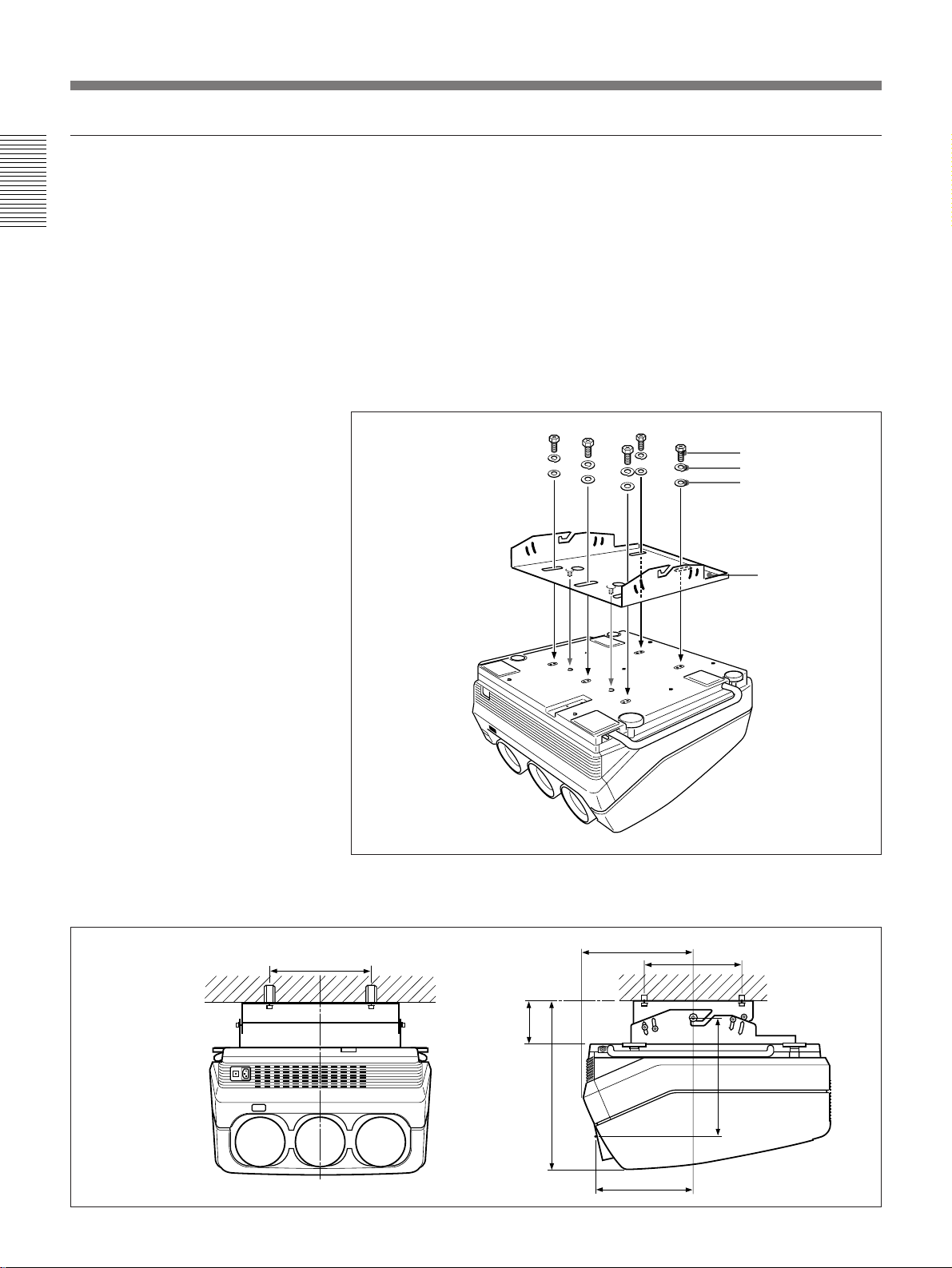
Attaching the PSS-70 Projector Suspension Support
Attach the projector mounting bracket to the bottom surface of the
projector.
Installation
Use five each of the M8×20 bolts, M8 washers and spring washers, all of
which are supplied with the PSS-70.
1 Align the two projections on the projector mounting bracket with the
receptacles on the bottom surface of the projector.
2 Fasten the five bolts and washers to fix the mounting bracket to the five
holes for attaching the PSS-70 on the bottom surface of the projector.
M8×20 bolt
Spring washer
M8 washer
Installation dimensions
254 (10)
Projector
mounting
bracket
For attaching the PSS-70 to the ceiling, refer to the Installation Manual of the
PSS-70 Projector Suspension Support.
301.8 (11 7/8)
/32)
17
254
(10)
12 (EN) Installation
114.8 (14
457.4 (18)
263.8 (10 3/8)
)
/16
11
322.5
(12
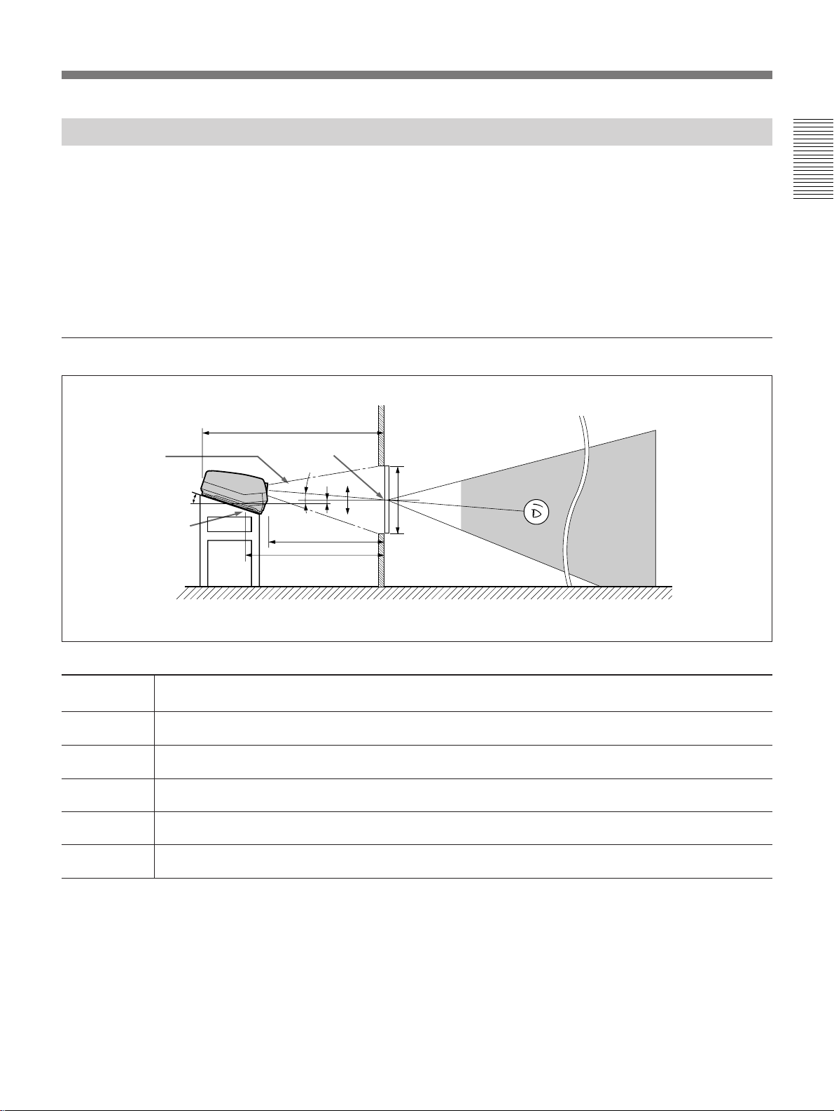
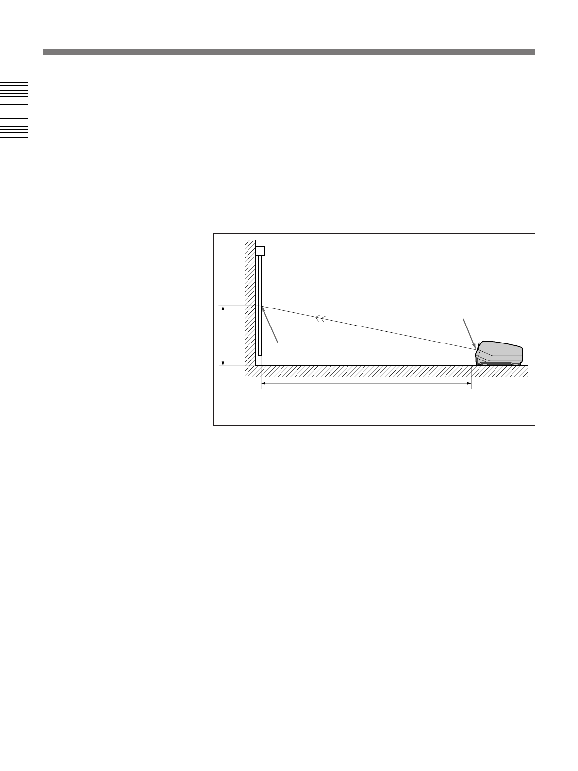
Floor Installation Using Rear Projection Flat Screen
What is the optical axis angle?
The optical axis angle is the angle between the horizontal level line and the
straight line from the center of the projector’s green lens to the center of
the screen. When using a rear projection screen, you can get the brightest
picture when the center of the screen is aligned with a straight line
extension of the center of the green lens.
Therefore, the most suitable optical axis angle varies depending on the
height of the screen and your line of sight.
When the optical axis angle is 2°
Wall
G
Optical axis
angle
15.5°
Standard hole for
installation
Center of the screen
2°
E
F
–
B
0
+
A
Installation
Floor
Unit: mm (inches)
Screen size
(inches)
A (Vsize) 914 1067 1219 1372 1524 1829 2286 2743 3048 3810
B (Hcent) 140 130 120 110 100 80 49 18 -3 -54
E (Xlens) 1977 2265 2556 2846 3136 3712 4599 5482 6075 7544
F (Lhole) 2172 2460 2751 3041 3331 3907 4794 5677 6270 7739
G (Lmax) 2655 2943 3234 3524 3814 4390 5277 6160 6753 8222
60 70 80 90 100 120 150 180 200 250
(36) (42) (48) (54) (60) (72) (90) (108) (120) (150)
(5 5/8) (5 1/4) (4 3/4) (4 3/8) (4) (3 1/4) (1 15/16)(23/32)(-
(77 7/8) (89 1/4) (100 3/4) (112 1/8) (123 1/2) (146 1/4) (181 1/8) (215 7/8) (239 1/4) (297 1/8)
(85 5/8) (96 7/8) (108 3/8) (119 3/4) (131 1/8) (153 7/8) (188 3/4) (223 5/8) (246 7/8) (304 3/4)
(104 5/8) (115 7/8) (127 3/8) (138 3/4) (150 1/4) (172 7/8) (207 7/8) (242 5/8) (265 7/8) (323 3/4)
1
/8) (-2 1/8)
Necessary parts modifications
Changing the polarity used for “Floor installation, rear projection”
For details, see “Changing the Polarity” on page 17 (EN).
Installation 13 (EN)

Installation Diagrams
Variable Range of the Optical Axis Angle in Rear Projection
You can change the optical axis angle within the following ranges by
adjusting flapping of the lens.
Installation
For adjusting flapping of the lens, see “Adjusting flapping of the green lens” on
page 64 (EN).
On floor installation
You can install the projector within an angle of optical axis –13.5° to +2°.
+2°
–13.5°
Wall
n : Optical axis
– · – · : Horizontal line
Floor
On ceiling installation
You can install the projector within an angle of optical axis +3° to +13.5°.
Ceiling
+13.5°
+3°
Wall
n : Optical axis
– · – · : Horizontal line
14 (EN) Installation
Notes on Screen
Screen size
The screen size is the diagonal length of the screen in
inches, while the aspect ratio of the screen is 3:4. The
ratio of the screen height, width, and diagonal is 3:4:5.
4
3
If you use a screen with 3:4 aspect ratio whose size is
not given in the table below, you can calculate the
screen height and width from the screen size (inches)
as follows.
Calculate at the conversion rate of 25.4 mm to the
inch.
Height (mm) = Screen size × 25.4 ×
Width (mm) = Screen size × 25.4 × 4/5
Screen size and dimensions
Screen size (inches)
(Diagonal) Height (mm) Width (mm)
60 914 1219
70 1067 1422
80 1219 1626
90 1372 1829
100 1524 2032
120 1829 2438
150 2286 3048
180 2743 3658
200 3048 4064
250 3810 5080
5
3
/5
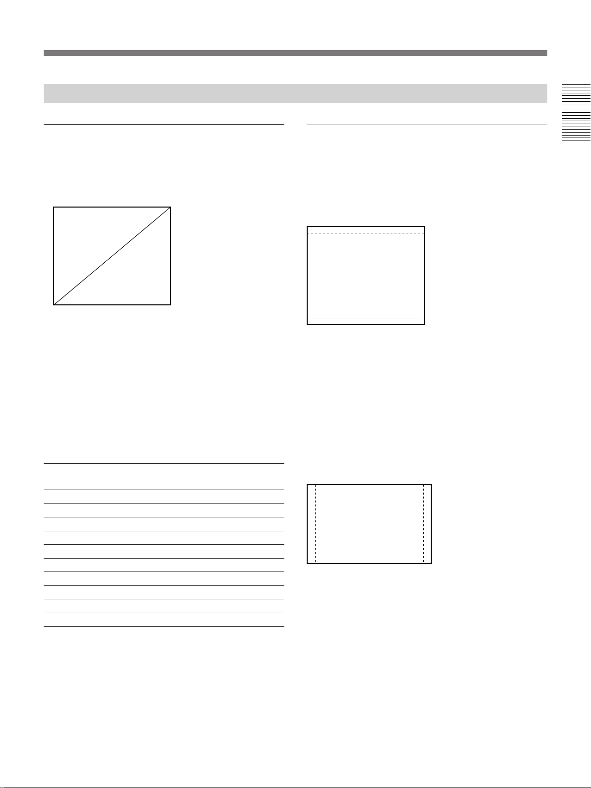
Screens with an aspect ratio other than
3:4
When the height is greater
Calculate the screen size with 3:4 aspect ratio from the
screen height as shown below. Install the projector and
screen in accordance with the screen size obtained.
--- : Screen whose aspect ratio is 3:4
5
Screen size (inch) = (height (mm) ×
Example: When the screen height is 1500 mm
5
(1500 (mm) ×
/3) × 1/25.4 = Approx. 98 inches
When the width is greater
Calculate the screen size with 3:4 aspect ratio from the
screen width as shown below. Install the projector and
screen in accordance with the screen size obtained.
---: Screen whose aspect ratio is 3:4
Screen size (inch) = (width (mm) ×
Example: When the screen width is 2000 mm
5
(2000 (mm) ×
/4) × 1/25.4 = Approx. 98 inches
/3) × 1/25.4
5
/4) × 1/25.4
Installation
Installation 15 (EN)
Installation Diagrams
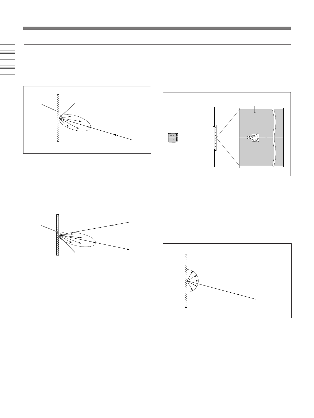
Types of screen
Front projection screen for floor installation
The bead screen is recommended. A screen of this type
reflects the brightest light.
Installation
Bead screen
Center of the screen
Brightest picture
Front projection screen for ceiling installation
The silver screen is recommended. You can get a
picture that is two to four times brighter than that of
the white screens.
Silver
screen
Projector
Projector
Rear projection screen
A screen manufactured using two sheets, the fresnel
and lenticular, is recommended for a bright and clear
full-screen picture projection.
Horizontal viewing areaScreen
Projector
White screen
When viewers watch the projected picture in a wide
area, you can obtain a picture that appears equally
bright from all parts of the room using the white
screen for both floor and ceiling installations. Note
that you will not be able to get a clear picture in this
case unless the room is dark.
Center of the screen
Brightest picture
Projector
16 (EN) Installation
Modifying Parts
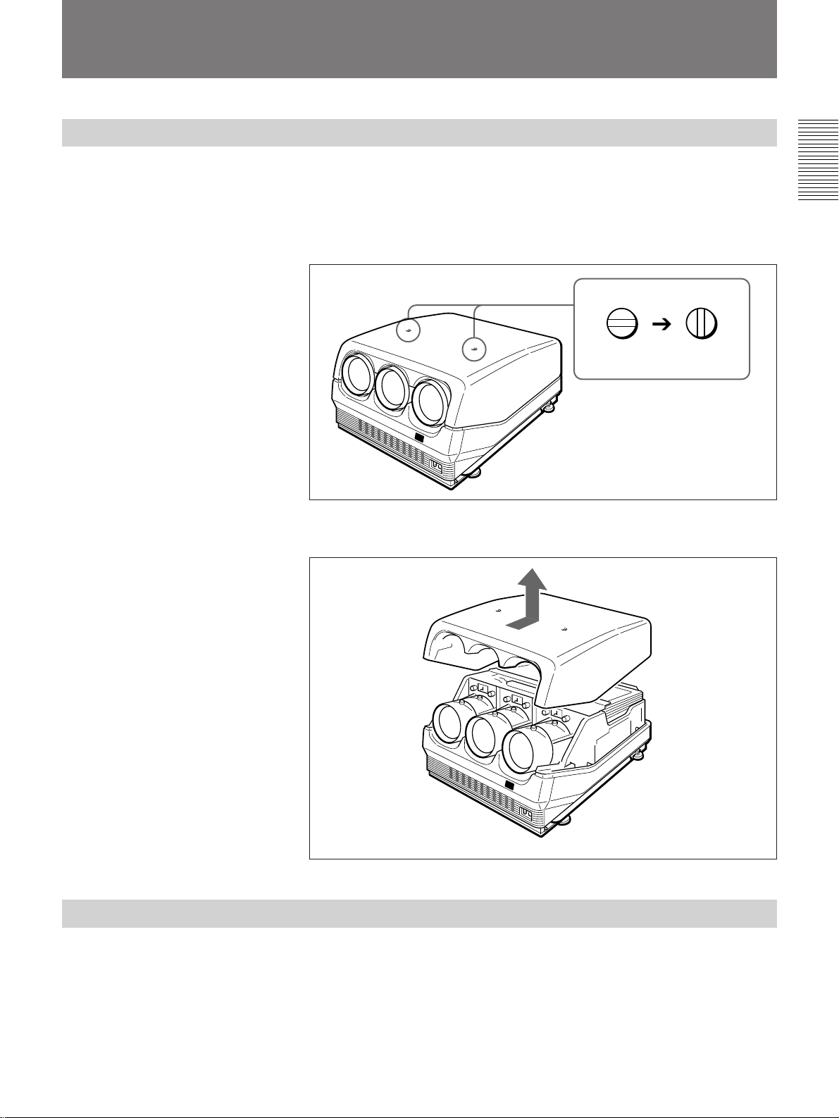
Removing the Upper Cover
1 Turn off the main power of the projector.
2 Unlock the two screws on the projector by using a screwdriver or a
coin edge, and then open the upper cover.
Locked Unlocked
3 Slide the upper cover towards the rear and lift it to remove.
Installation
Changing the Polarity
The polarity of the projector is adjusted to use the projector for front
projection on the floor.
When the projector is installed on the ceiling or used in rear projection, it
is necessary to change the settings of the polarity switch and the polarity
connectors.
(continued)
Installation 17 (EN)

Modifying Parts
How to change the polarity
Installation
1 Turn off the power of the projector.
2 Remove the upper cover.
For how to remove the upper cover, see page 17 (EN).
3 Press to open the connector cover.
4 Check the polarity switch position and the connecting position of the
polarity connectors.
For the installation methods of the projector and the settings of the switch and
the connectors, see the diagram on the next page.
Polarity switch position
Lens side
(Factorypreset)
Board
side
Connector cover
Connecting position of
the polarity connectors
Lens side
(Factory-preset)
Board side
5 Change the switch position and/or the connecting position of the
connectors, if necessary.
Polarity switch: Set to the lens side or board side position.
Polarity connectors: Disconnect the three connectors, then turn them
over (180°) and reinsert into the receptacles on the lens side or the
board side.
18 (EN) Installation
6 Make sure to insert the connectors correctly and to set the switch to the
correct position, then restore the connector cover and the upper cover.
Note
If the connector cover does not shut firmly, the power of the projector is not turned
on.

Installation methods and settings of the polarity switch and the polarity connectors
Polarity and on-screen display
Installation
methods
Front projection,
Position of the
switch
L
Connecting
position of the
connectors
L
On-screen display
by default (See
below.)
Correct
floor
Front projection,
B
B
C
ceiling
Rear projection,
L
B
A
floor
Rear projection,
B
L
B
ceiling
Others
Display letters on the screen so that you can determine
which changes to make.
For on-screen display and necessary changes, see below.
L: Lens side
B: Board side
Note
When installing the projector, make sure to leave space of more than 30 cm (12
inches) between the wall or floor and the ventilation holes of the projector.
Installation
When the projector is installed on the ceiling or used in rear projection
without changing the polarity, one of the following on-screen displays
appears. In this case, you have to change the polarity corresponding to the
installation methods.
A The letters are backward.
Change the connecting position of
the polarity connectors.
INPUT-A
For optimum
performance,
white screen will
remain for 20min.
For immediate use,
push [MENU] key.
B The letters are upside
down.
Change the polarity switch position.
push [MENU] key.
For immediate use,
remain for 20min.
white screen will
performance,
For optimum
INPUT-A
C The letters are upside down and backward.
Change the polarity switch position and the connecting position of the
polarity connectors.
push [MENU] key.
For immediate use,
remain for 20min.
white screen will
performance,
For optimum
INPUT-A
Installation 19 (EN)
Modifying Parts
Adjusting the CRT Conversion Angle
Installation
Adjust the CRT conversion angle so that the three CRT images converge
exactly.
1 Remove the upper cover.
For how to remove the upper cover, see page 17 (EN).
2 Turn on the power of the projector.
3 Set the remote control to the service adjustment mode.
For details, see “Preparation” on page 37 (EN).
4 Reset the green, red and blue centering.
For details, see “Resetting the Data” on page 100 (EN).
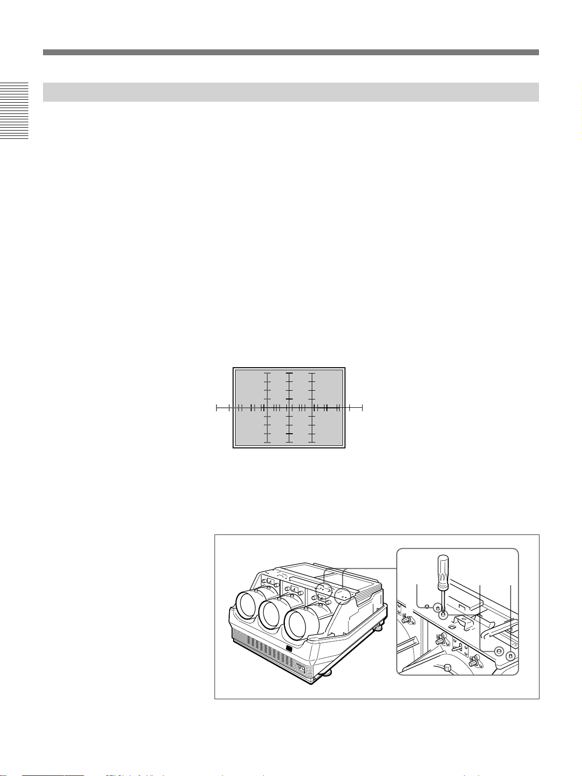
5 Make sure that the on-screen display is shown as follows:
• The center of the green HATCH pattern aligns with the horizontal
center of the screen.
• The center of the red and blue HATCH patterns align at even
intervals from the green HATCH pattern.
If the center of the green HATCH pattern does not align with the center
of the screen, re-install the projector correctly.
6 Loosen the four red CRT fixing screws (black) by using the Philips
screwdriver. Make sure not to remove the screws.
Black
screws
Black
screws
Black
screws
20 (EN) Installation

7 Move the red lens right and left to adjust the CRT conversion angle so
that the vertical line of the red HATCH pattern converges with that of
the green pattern.
8 When the HATCH pattern aligns with the green pattern correctly,
tighten the four CRT fixing screws loosened in step 6.
9 Repeat steps 6 to 8 to loosen the four blue CRT fixing screws (black),
adjust the blue CRT conversion angle and tighten the four CRT fixing
screws.
Installation
Installation 21 (EN)
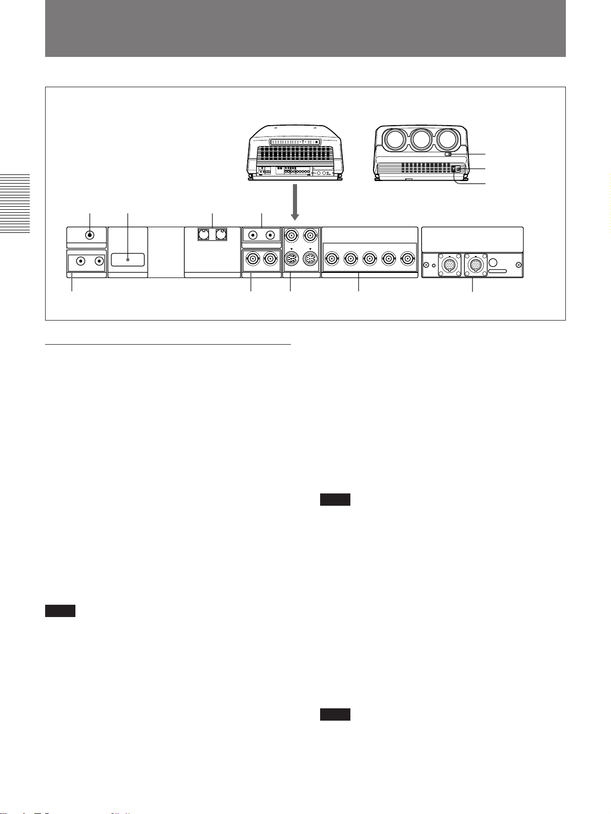
Location and Function of Connectors
12 3 4
Connections
TRIGGER
IN OUT
PLUG IN POWER
CONTROL S
RS-422A
REMOTE
INDEX
5
Rear
1 TRIGGER connector (minijack)
When the projector is turned on, 5 V is output and
when it is turned off, 0 V is output. However, the
connector is not used as the power source since the
power is not output.
2 RS-422A REMOTE connector (D-sub 9-pin)
Used to expand the system connections using the RS422A interface.
Before using the connector, remove the red cap.
3 INDEX NO. switches
When multiple projectors are connected, set the index
number of each projector.
To display the index number on the screen, press the
NORMAL key, and the ENTER key on the remote
control.
Note
If you set the index number to “00,” the projector does not
operate.
4 ABL (Automatic Brightness Limiter) LINK IN/
OUT jacks (minijack)
When connecting multiple projectors, connects the
ABL LINK OUT jack to the ABL LINK IN jack on
another projector . You can synchronize the brightness
limiting point among the projectors, allowing to make
the whole screen brightness uniform.
IN OUT
ABL LINK
IN IN
VIDEO
6
Rear
Front
!™
!¡
!º
Y IN
C IN
S VIDEO
R
OUTOUT
R-Y/P
R
YGB-Y/P
INPUT A
B SYNC/HD VD
B
REMOTE1
IN OUT
MODE
78 9
5 CONTROL S jacks
IN/PLUG IN POWER (5 V) jack (stereo minijack):
Connects to the CONTROL S OUT jack of other
Sony equipment. Also connects to the CONTROL
S OUT jack of the supplied remote control with the
supplied remote control cable (stereo cable) to be
used as a wired remote control. In this case, this
jack supplys 5 V to the remote control as power
source.
OUT jack (stereo minijack): Connects to the
CONTROL S IN jack of other Sony equipment.
Note
When using this jack, the remote control detector on the
projector does not function.
6 VIDEO IN/OUT connectors
VIDEO IN connector (BNC type): Connects to the
composite video output of the video equipment.
VIDEO OUT connector (BNC type): Connects to
the composite video input of a color monitor.
7 S VIDEO IN/OUT connectors
Y IN, C IN connectors (BNC type): Connects to the
Y and C video outputs of the video equipment.
S VIDEO IN/OUT connectors (4-pin, mini-DIN
type): Connects to the S video output or input
connector of the video equipment.
Note
The S VIDEO IN connector is disconnected when a cable
is connected to the Y/C IN connectors.
22 (EN) Connections
Connections
8 INPUT A connectors (BNC type)
R
R/R-Y/P
, G/Y, B/B-Y/PB, SYNC/HD, VD
connectors: Connect to the outputs of a computer or
a video camera. According to the connected
equipment, the RGB (R, G, B), component (R-Y, G,
B-Y) or HDTV (P
R, Y, PB) signal is selected.
9 Signal interface board attachment part (INPUT
B)
The IFB-40 Signal Interface Board is installed by
default. Other optional signal interface boards can be
attached to this section instead of the IFB-40.
Indicator (red): Lights up when the input of the IFB-
40 is selected.
REMOTE 1 IN connector (14-pin multi): When
connecting two projectors, connect to the REMOTE
1 OUT connector on the IFB-40 installed to another
projector.
REMOTE 1 OUT connector (14-pin multi):
Connect to the REMOTE 1 IN connector on the
IFB-40.
MODE selector: Turn the control switch of the
MODE selector to the appropriate position
according to the length of the cable connected to the
REMOTE 1 OUT connector.
Front
0 AC IN socket
Connect the supplied AC power cord.
!¡ MAIN POWER switch
!™ Front remote control detector
Connections
Cable length
Type of cable
Position
up to 2 m
SIC-M-1
CCQ-2BRS
1
up to 10 m
SIC-M-5
CCQ-5BRS
CCQ-10BRS
2
up to 25 m
SIC-M-15
CCQ-25BRS
SIC-M-25
3
up to 50 m
SIC-M-50
CCQ-50BRS
4
Connections 23 (EN)
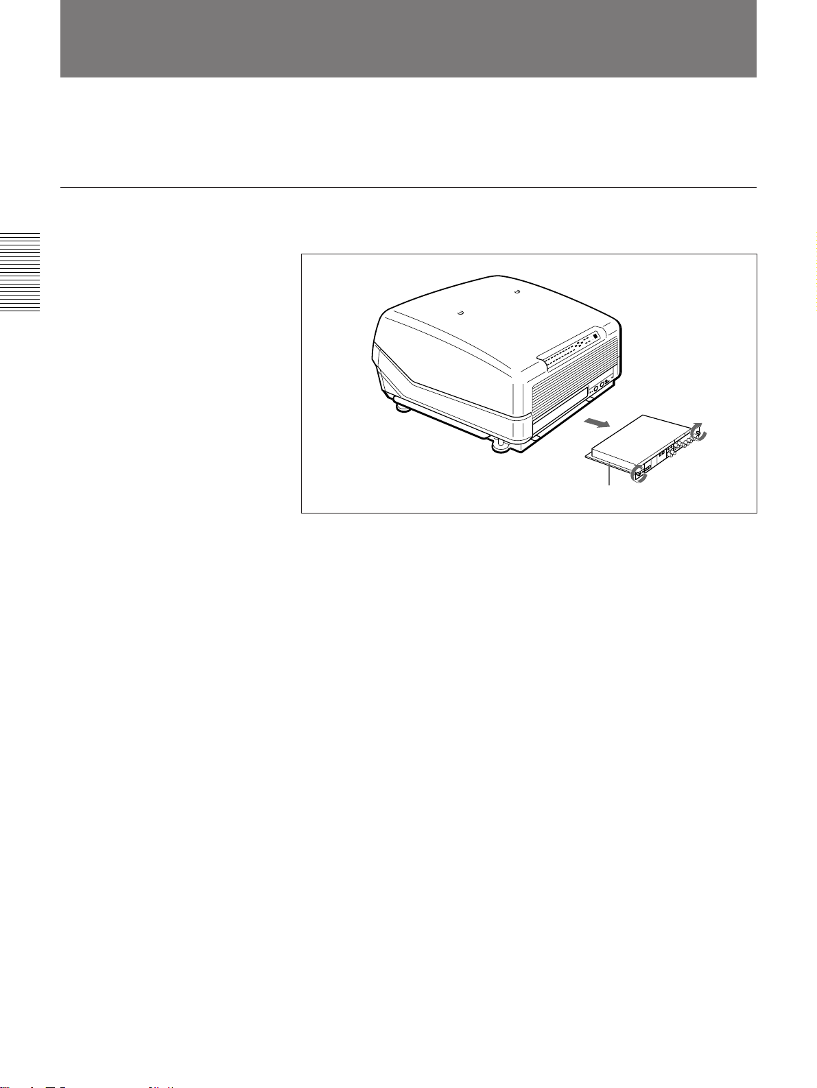
Switching the 75-ohm Terminate Connectors
Removing the A Board
Connections
Depending on the connections of the computer and color monitor to the
projector, it may be necessary to switch the 75-ohm terminate connectors
on the A board at the rear of the projector.
1 Loosen the two screws at the rear of the projector to remove the
connector panel.
A board
2 Switch the CN1004, CN1005 and CN1006 on the A board.
For details, see “Setting the CN1006 (R), CN1005 (G) and CN1004 (B)
75-ohm terminate connectors.”
3 Replace the A board by reversing step 1.
24 (EN) Connections

Setting the CN1006 (R), CN1005 (G) and CN1004 (B) 75-ohm terminate connectors
75 Ω (pin position 3): This position is selected at the factory.
OPEN (pin position 1): Set to this position when the input signal is
distributed into other equipment using a branch connector and is
terminated at 75 ohms on that equipment.
Pin positions set at the factory
OPEN
CN1004
1
OPEN
2
3
75
1k 75
123
CN1003
1k 75
123
CN1002
A board
CN1001
321
HS HS SEP
1
OPEN
CN1006
NORM
2
3
75 75
321
CN1005
How to switch the connector
Connections
1
2
3
3
1
2
Note
The pin positions of the CN1001, CN1002 and CN1003 connectors are set at the
factory as illustrated. Do not change the settings.
Connections 25 (EN)

Connecting Directly to the Projector
You can expand the system connections by using the IFB-40 Signal
Interface Board which is installed to the projector by default, or in
combination shown in the examples below.
When multiple input sources are connected to the projector
Use the IFU-1271/1271M Signal Interface Unit.
Rear
Connections
TRIGGER
IN OUT
PLUG IN POWER
CONTROL S
RS-422A
REMOTE
Color monitor
Video equipment
INDEX
to video input
to video output
to S Video output
Setting up
• Set INPUT-A in the SET SETTING menu to RGB.
For details, see “The SET SETTING Menu” on page 50 (EN).
• Select VIDEO or S VIDEO by pressing the INPUT SELECT keys on the
remote control or by setting VIDEO in the INPUT SELECT menu.
For details, see “The INPUT SELECT Menu” on page 44 (EN).
• Switch the 75-ohm terminate connectors according to the connections of
the computer and color monitor.
For details, see “Switching the 75-ohm Terminate Connectors” on page 24 (EN).
IN OUT
ABL LINK
IN
VIDEO
VIDEO IN
Y IN
C IN
OUTOUT
R-Y/PR Y B-Y/PB
IN
S VIDEO
S VIDEO IN
VIDEO OUT
to RGB Input
R G B SYNC/HD VD
INPUT A
G
B
R
SYNC/HD
to RGB output
IFU-1271/1271M
IFB-12
to RGB output
SMF-401, etc.
VD
to RGB
input
REMOTE1
IN OUT
Color monitor
MODE
Computer
26 (EN) Connections

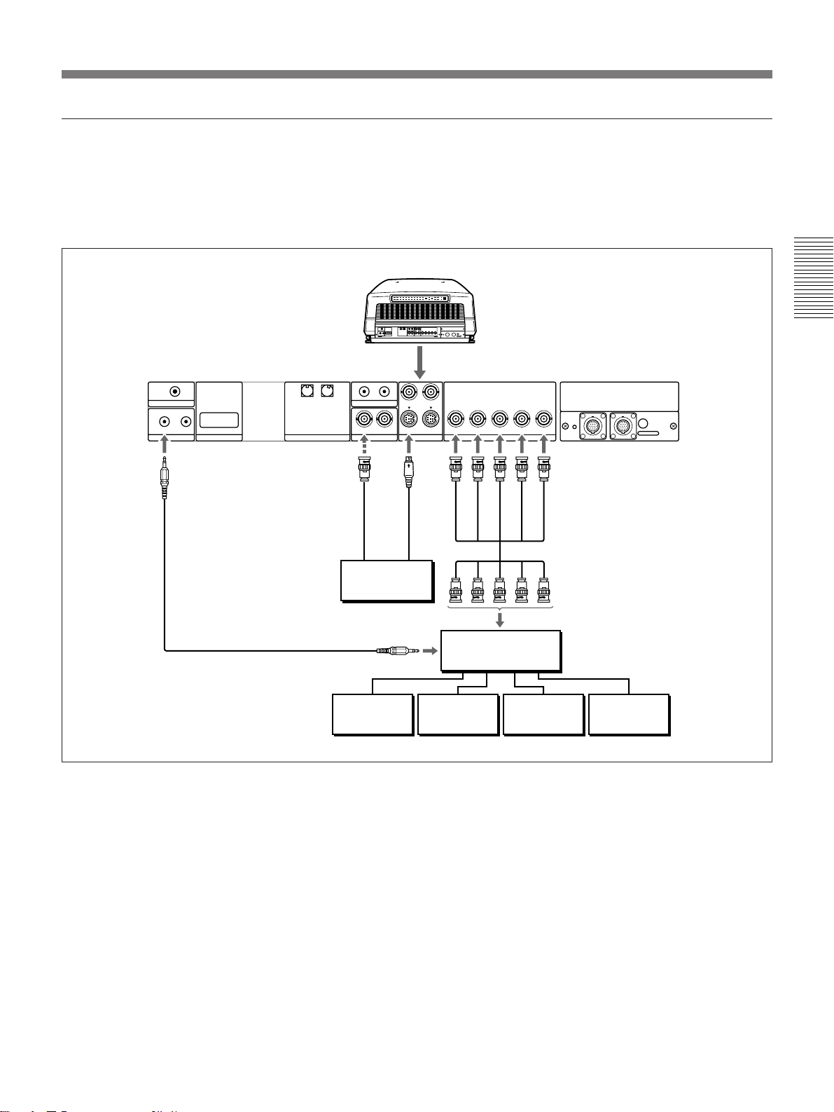
Using the Signal Interface Switcher
When you connect the PC-1271/1271M Signal Interface Switcher (not
supplied) to the IFB-40 Signal Interface Board (installed on the projector by
default), you can connect easily various input sources.
You can select up to 16 inputs by pressing the SWITCHER/INDEX keys on
the remote control or by setting SWITCHER in the INPUT SELECT menu.
When the switcher is connected to the projector using the SIC-M or CCQ-BRS connecting cable
Rear
IFB-40 Signal Interface Board
Connections
TRIGGER
IN OUT
PLUG IN POWER
CONTROL S
RS-422A
REMOTE
Video
equipment
Computer
INDEX
to video output
to S Video output
to RGB OUT
Choose the appropriate cable from the following table.
1 m 2 m 5 m 10 m 15 m 25 m 50 m
— CCQ-2BRS CCQ-5BRS CCQ-10BRS — CCQ-25BRS CCQ-50BRS
SIC-M-1 — SIC-M-5 — SIC-M-15 SIC-M-25 SIC-M-50
Notes
• Insert the female and male plugs of the SIC-M or CCQ-BRS cable correctly.
• You can extend the SIC-M or CCQ-BRS cable up to 50 m.
• The video signal input to the signal interface board installed to the INPUT B
section should not exceed 70 MHz. When projecting the video signal which
exceeds 70 MHz, connect the signal source to the INPUT A connectors using the
5BNC cables.
IN OUT
ABL LINK
OUT
IN
VIDEO
VIDEO IN
Y IN
C IN
OUT
IN
S VIDEO
S VIDEO IN
Video
equipment
R-Y/P
R
R
YGB-Y/P
INPUT A
B SYNC/HD VD
B
REMOTE1
IN OUT
MODE
IN
G
B
VD
SYNC/HD
SIC-M or CCQ-BRS
connecting cable
R
to REMOTE 1 OUT
PC-1271/1271M
Switcher
Setting up
• Set INPUT-A in the SET SETTING menu to RGB.
For details, see “The SET SETTING Menu” on page 50 (EN).
• Select VIDEO or S VIDEO by pressing the INPUT SELECT keys on the
remote control or by setting VIDEO in the INPUT SELECT menu.
For details, see “The INPUT SELECT Menu” on page 44 (EN).
• Set the SINGLE/SECOND/OTHER select switch on the switcher to
SINGLE.
Connections 27 (EN)

Using the Signal Interface Switcher
When the switcher is connected to the projector using both the SIC-M or CCQ-BRS
connecting cable and the 5BNC cables (5BNC mode 1)
When you connect both the video and RGB signal input sources to the
switcher, use the SIC-M or CCQ-BRS connecting cable and the BNC
cables for connection between the projector and switcher.
Rear
Connections
IFB-40 Signal Interface Board
TRIGGER
IN OUT
PLUG IN POWER
CONTROL S
RS-422A
REMOTE
Video equipment
INDEX
to video output
to S video output
Notes
• Insert the female and male plugs of the SIC-M or CCQ-BRS cable correctly.
• You can extend the SIC-M or CCQ-BRS cable up to 50 m.
• The video signal input to the signal interface board installed to the INPUT B
section should not exceed 70 MHz. When projecting the video signal which
exceeds 70 MHz, connect the signal source to the INPUT A connectors using the
5BNC cables.
IN OUT
ABL LINK
IN IN
VIDEO
VIDEO IN
Video
equipment
Y IN
C IN
OUTOUT
R-Y/PR Y B-Y/PB
S VIDEO
R
S VIDEO IN
5BNC cables
to MONITOR OUT
R G B SYNC/HD VD
INPUT A
B
G
SYNC/HD
HDTV/
Component
equipment
REMOTE1
IN OUT
IN
VD
SIC-M or CCQ-BRS
connecting cable
to REMOTE 1 OUT
PC-1271/1271M
Switcher
Computer
MODE
Computer
28 (EN) Connections
Setting up
• Set INPUT-A to RGB and 5BNC MODE to ON in the SET SETTING
menu.
For details, see “The SET SETTING Menu” on page 50 (EN).
• Select VIDEO or S VIDEO by pressing the INPUT SELECT keys on the
remote control or by setting VIDEO in the INPUT SELECT menu.
For details, see “The INPUT SELECT Menu” on page 44 (EN).
• Set the SINGLE/SECOND/OTHER select switch on the switcher to
SINGLE.
When the switcher is connected to the projector using the 5BNC cables (5BNC mode 2)
When the switcher to be connected is more than 50 m away from the
projector, or the SIC-M or CCQ-BRS cable cannot be used for the
connection between the projector and switcher, connect the RGB signal
sources to the switcher and the video signal sources to the projector.
Rear
Connections
TRIGGER
IN OUT
PLUG IN POWER
CONTROL S
CONTROL S IN
Remote control
cable (supplied)
RS-422A
REMOTE
INDEX
IN OUT
ABL LINK
IN IN
VIDEO
Y IN
S VIDEO
C IN
R G B SYNC/HD VD
OUTOUT
R-Y/PR Y B-Y/PB
INPUT A
REMOTE1
IN OUT
MODE
S
VIDEO IN
VIDEO
IN
G
B
SYNC/HD
5BNC cables
VD
to video
output
R
to S
video
output
Video
equipment
to CONTROL S
OUT
PC-1271/1271M
to MONITOR OUT
Switcher
Video
equipment
15 K RGB/HD/
component
equipment
ComputerComputer
Setting up
• Set INPUT-A to RGB and 5BNC MODE to ON in the SET SETTING
menu.
For details, see “The SET SETTING Menu” on page 50 (EN).
• Select VIDEO or S VIDEO by pressing the INPUT SELECT keys on the
remote control or by setting VIDEO in the INPUT SELECT menu.
For details, see “The INPUT SELECT Menu” on page 44 (EN).
• Set the SINGLE/SECOND/OTHER select switch on the switcher to
SINGLE.
• When the HDTV signal is input to the switcher, set the output of the
connected equipment or the IFB-1301 Signal Interface Board installed to
the switcher to GBR OUT.
• When the component signal is input to the switcher, set the output of the
connected equipment or the IFB-1200 Signal Interface Board installed to
the switcher to RGB OUT.
Connections 29 (EN)
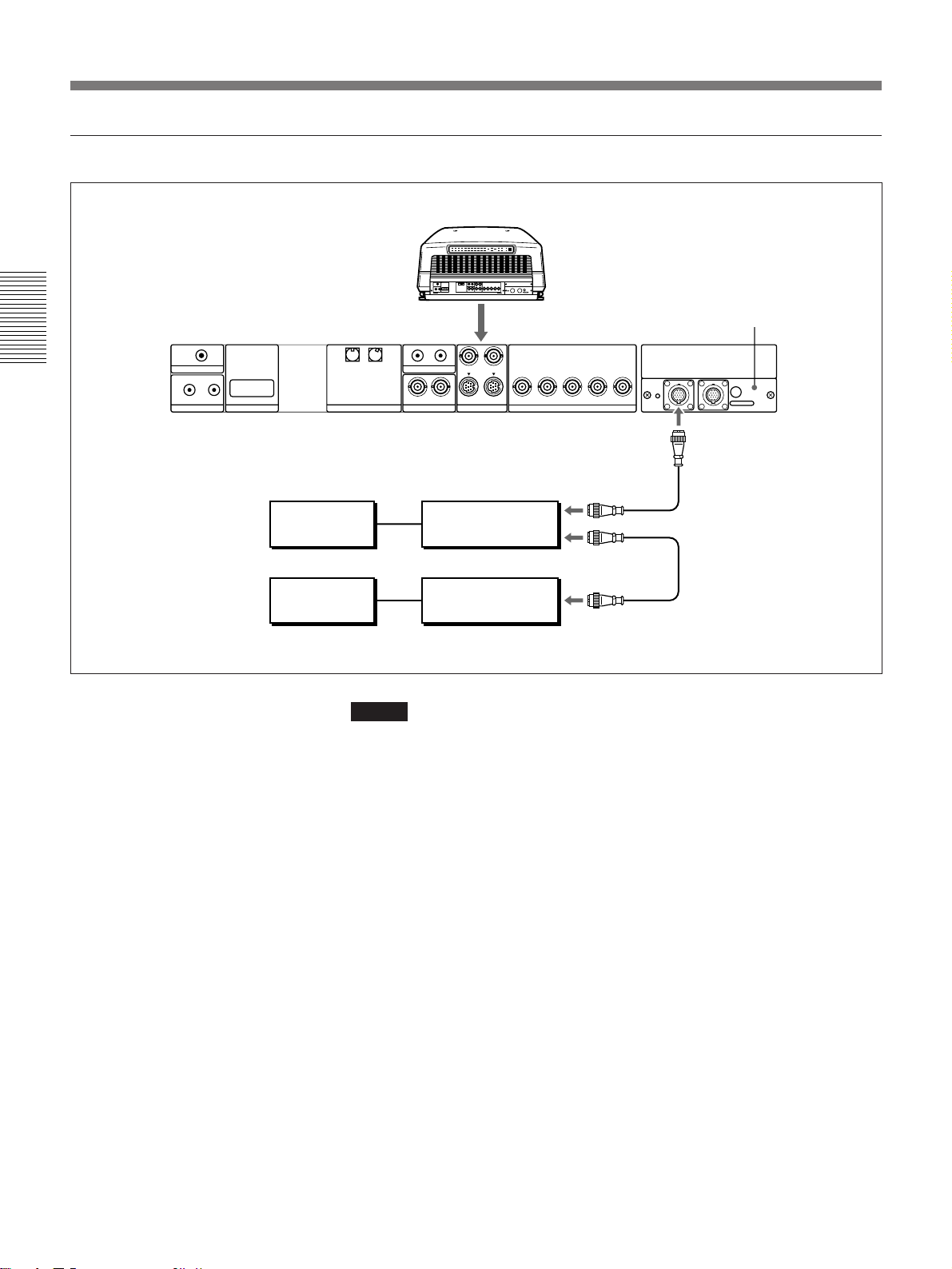
Using the Signal Interface Switcher
When two signal interface switchers are connected
Rear
IFB-40 Signal Interface Board
Connections
TRIGGER
IN OUT
PLUG IN POWER
CONTROL S
RS-422A
REMOTE
Video
equipment
Video
equipment
INDEX
IN OUT
ABL LINK
IN IN
VIDEO
Y IN
S VIDEO
C IN
R G B SYNC/HD VD
OUTOUT
R-Y/PRY B-Y/P
INPUT A
REMOTE1
B
IN OUT
MODE
IN
SIC-M or CCQ-BRS
to REMOTE 1 OUT
connecting cable
First switcher
PC-1271/1271M
to REMOTE 1 IN
SIC-M or CCQ-BRS cable
Second switcher
PC-1271/1271M
to REMOTE 1 OUT
Notes
• Insert the female and male plugs of the SIC-M or CCQ-BRS cable correctly.
• You can extend the SIC-M or CCQ-BRS cable between the projector and the
switcher up to 50 m.
• The video signal input to the signal interface board installed to the INPUT B
section should not exceed 70 MHz.
30 (EN) Connections
Setting up
• Set the SINGLE/SECOND/OTHER select switch on the first switcher to
SINGLE.
• Set the SINGLE/SECOND/OTHER select switch on the second switcher
to SECOND.
 Loading...