

Page 1
User Guide
Digital Living System™
VGX-XL2A
Page 2

VAIO® VGX-XL2A Disclaimers, Notes, Warnings
NOTICE
© 2005 Sony Electronics Inc. Reproduction in whole or in part without written permission is prohibited. All rights reserved. This manual and the software described herein, in whole or in part,
may not be reproduced, translated, or reduced to any machinereadable form without prior written
approval.
SONY ELECTRONICS INC. PROVIDES NO WARRANTY WITH REGARD TO THIS MANUAL,
THE SOFTWARE, OR OTHER INFORMATION CONTAINED HEREIN AND HEREBY
EXPRESSLY DISCLAIMS ANY IMPLIED WARRANTIES OF MERCHANTABILITY OR FITNESS
FOR ANY PAR TICULA R PURPOSE WITH REG ARD T O THIS MANUAL, THE SOFTWARE, OR
SUCH OTHER INFORMATION. IN NO EVENT SHALL SONY ELECTRONICS INC. BE LIABLE
FOR ANY INCIDENTAL, CONSE QUENTIAL, OR SPECIAL DAMAG ES, WHETHER BASED ON
TORT, CONTRACT, OR OTHERWISE, ARISING OUT OF OR IN CONNECTION WITH THIS
MANUAL, THE SOFTWARE, OR OTHER INFORMATION CONTAINED HEREIN OR THE USE
THEREOF.
SONY CANNOT WARRANT THAT THE FUNCTIONS DESCRIBED IN THIS GUIDE WILL BE
UNINTERRUPTED OR ERROR-FREE. SONY ALSO ASSUMES NO RESPONSIBILITY, AND
SHALL NOT BE LIABLE FOR ANY DAMAGES TO, OR VIRUSES THAT MAY INFECT, YOUR
COMPUTER EQUIPMENT, OR OTHER PROPERTY ON ACCOUNT OF YOUR ACCESS TO,
USE OF, OR BROWSING IN ANY DESCRIBED WEB SITE, OR YOUR DOWNLOADING OF
ANY MATERIALS, DATA, TEXT, IMAGES, VIDEO, OR AUDIO FROM ANY DESCRIBED WEB
SITE. WEB SITE INFORMATION IS OBTAINED FROM VARIOUS SOURCES AND MAY BE
INACCURATE. COPIES OF COPYRIGHTED INFORMATION MAY ONLY BE MADE FOR
LEGALLY PERMISSIBLE PURPOSES.
Sony Electronics Inc. reserves the right to make any modification to this manual or the information contained herein at any time without notice. The software described herein is governed by
the terms of a separate user license agreement.
ImageStation, ATRAC3, and i.LINK are trademarks or registered trademarks of Sony.
This product contains software owned by Sony and licensed by third parties. Use of such software is subject to the terms and conditions of license agreements enclosed with this product.
Some of the software may not be transported or used outside the United States. Sof tware specifications are subject to change without notice and may not necessarily be identical to current retail
versions.
Certain product(s) included with this computer may include features such as copy protection and
content management technology. USE OF THE SOFTWARE PRODUCT(S) REQUIRES
AGREEMENT TO APPLICABLE END USER AGREEMENTS AND FULL COMPLIANCE WITH
APPLICABLE PRODUCT ACTIVATION PROCEDURES. Product activation procedures and pri
vacy policies will be detailed during initial launch of the software product(s), or upon certain reinstallations of the software product(s), or reconfigurations of the computer, and may be completed
by Internet or telephone (toll charges may apply). Updates and additions to software may require
an additional charge. Subscriptions to online service providers may require a fee and credit card
information. Financial services may require prior arrangements with participating financial institu
tions.
Important information for Canadian customers: Your new Media Changer/Recorder
includes certain software versions or upgrades, and Internet services or offers that are
available to U.S. customers only.
Sony, VAIO, the VAIO logo, VAIO Digital Studio, VAIO Media, VAIO Media Music Server, VAIO
Media Photo Server, VAIO Media Video Server, VAIO Zone, Click to DVD, CLIÉ, DVgate Plus,
Handycam, MagicGate, Memory Stick, Memory Stick Duo, the Memory Stick logo, OpenMG,
MICROMV, SonicStage, PictureGear are trademarks or registered trademarks of Sony Electron
ics.
-
-
-
Page 3

Intel and Pentium are trademarks or registered trademarks of the Intel Corporation.
Microsoft, Windows, and the Windows logo are trademarks or registered trademarks of the
Microsoft Corporation.
PS/2 is a registered trademark of the IBM Corporation.
All other trademarks are trademarks or registered trademarks of their respective owners.
Page 4

Introduction
Chapter 1:
Getting Started
Welcome to the VAIO® VGX-XL2A Digital Living System™ User Guide. You
can download updated user guide information by opening VAIO
C
Central and selecting Documentation. This guide contains the following
information:
• Chapter 1: Getting Started
• Chapter 2: Setting Up Your VGX-XL2A DLS System
• Chapter 3: Hardware Upgrades & Maintenance
• Appendix A: Wireless Local Area Networks
• Appendix B: VAIO Media™ Software: Wirless Local Area Networks
• Appendix C: Setting Up Digital TV
• Appendix D: Hard Disk Drive Recovery
• Appendix E: RAID Configuration
• Appendix F: Troubleshooting
• Appendix G: Program Support
®
Support
What is the VGX-XL2A Digital Living System?
The VGX-XL2A DLS system is a powerful computer designed with the
livingroom and your digital entertainmen t needs in mind. Add a CD/DVD
changer or other perpherial devices, and it become the host for a state of the
art home entertainment system. Let the VGX-XL2A DLS system lead you into
the exciting world of VAIO
content management.
®
where new technologies are est ablished for d igital
VGX-XL2A Digital Living System 1
Page 5

Product Specifications
VGX-XL2A Personal Computer
For complete hardware specifications, go to VAIO® Support Central and
select Product Specifications. [Start > All Programs > VAIO Support
Central]
Operating System Software
The operating system for the VGX-XL2A Digital Living System™ is Microsoft®
®
Windows
added software provides you with additional features and PC capabilities and
when teamed with Media Center, provides you with an even greater
entertainment value.
Note: Even though the digital entertainment features of the VGX-XL2A
computer are designed to work through Media Center, the features can also
be accessed through independent software applications pre-installed on
XL2A computer . For a listing o f these and other pre-installed application, see
Sony Original Software and Other Software Applications.
XP Media Center Edition 2005, with Update Rollup 2. VAIO value-
2 VGX-XL2A Digital Living System
Page 6
Microsoft® Windows® Media Center Edition 2005
The following list contains a high-level overview of the features available to
you in Media Center. For in-depth information about each feature, go to the
specific topic in the VGX-XL2A Digital Living System™ Entertainment Guide
included with the packaging materials.
Feature Description
Play DVDs Insert a DVD movie into the optical drive slot to view
the movie or review specific movie information.
Online Spotlight The Online Spotlight provides Internet access to the
latest entertainment news and events.
My Pictures Categorize your pictures in as many folders as you
wish. Then, select a group to view a single picture or
a slide of all pictures in the folder.
My TV Take control of your TV viewing experience. Watch
live TV or record your favorite show for later viewing.
My Music Enjoy access to all the music stored on your hard
drive. Organize, locate, and play your favorite music
files in Media Center.
Create DVD Create DVDs from your favorite recorded TV series.
Select only the episodes you want to burn to DVD.
IMPORTANT: Sony supports the lawful use of technology and does
not endorse or encourage the use of our products for purposes
other than those permitted by copyright law. TV programs and
commercial DVDs that have been encrypted (protected) by the
broadcaster cannot be copied and played back on any player other
than the one recorded to.
More Programs To enhance you entertainment experience, lin ks have
been included to additional progr am s fo r you r
enjoyment.
Settings Set your personal preferences for your digi tal
entertainment experience. Review this section
carefully
VGX-XL2A Digital Living System 3
Page 7

Sony Original Software
The following Sony original software programs can be accessed by selecting
Windows Start > All Programs > [appl ication name]. For additional
information about a specific application, start the application an d go to the
Help file.
• Click to DVD™ - DVD Creation
• SonicStage® Mastering Studio™ - Audio Mastering & Re-Mastering
• DVgate Plus™- Digital Video
Note: Due to the constraints of using Component Video, DVgate Plus
will only open at 1080i resolutions.
• SonicStage® - Digital Music
• V AIO Media™ - Network File Sharing
• Image Converter - PSP™ (Play Station® Portable) hand held entertainment system
Other Software Applications
The following Sony original software programs can be accessed by selecting
Windows Start > All Programs > [appl ication name]. For additional
information about a specific application, start the application an d go to the
Help file.
• Adobe® Photoshop® Album Starter Edition - Photo Viewing and
Organizing
• Adobe® Premiere® Standard Edition - Basic V ideo Mastering and Editing
Tool from Adobe
• Adobe® Photoshop® Elements - Basic Photo Editing tool from Adobe
®
®
• Microsoft® Works 8.5 - Word Processing, Spreadsheet, Calendar,
Scheduling, Contact Management, and Database
• Microsoft® Office 2003 60-Day Student/Teacher Edition Trial
1. The Microsoft Office 2003 60-Day Trial software is intended for evaluation purposes
only. This trial software is installed on your system and you must activate the software
before you can use it. Product activation procedures will be detailed during initial
launch of the software; activation requires Internet access. This software has an expira
tion date of 60 days from date of first use, at which time the software will operate
under reduced-functionality mode, limiting end-user options and operations.
4 VGX-XL2A Digital Living System
1
-
Page 8

• Intuit Quicken® 2005 New User Edition (Previous Quicken Users may
require additional upgrade)
• InterVideo® WinDVD® - For DVD Playback
• Roxio® DigitalMedia SE - For Data DVD and CD Creation
Anti-virus and Recovery Software
• Norton® Internet Security™ 60-Day Subscription - Norton AntiVirus®,
Norton Personal Firewall, Norton Privacy Control, Norton AntiSpam
Norton Parental Control
Note: For additional information about Norton Security products, go to
http://www.symantec.com
•VAIO® Recovery Wizard
•VAIO® Control Center
• VAIO® Update
Getting to know the VGX-XL2A DLS System
Unpacking the VAIO XL2A Personal Computer
Make sure you have the following items:
VGX-XL2A PC Wireless Keyboard w/Intergrated Pointing Device
WLAN Antenna Power Cord Infrared Blaster Cable
HDMI™ Cable Optical S/PDIF Cable Keyboard Batteries (4)
®
,
Remote Batteries (2) HDMI™ to DVI-D
Adapter
Keep all packaging material in case you need to move or ship the XL2A
computer at a later time.
VGX-XL2A Digital Living System 5
Page 9
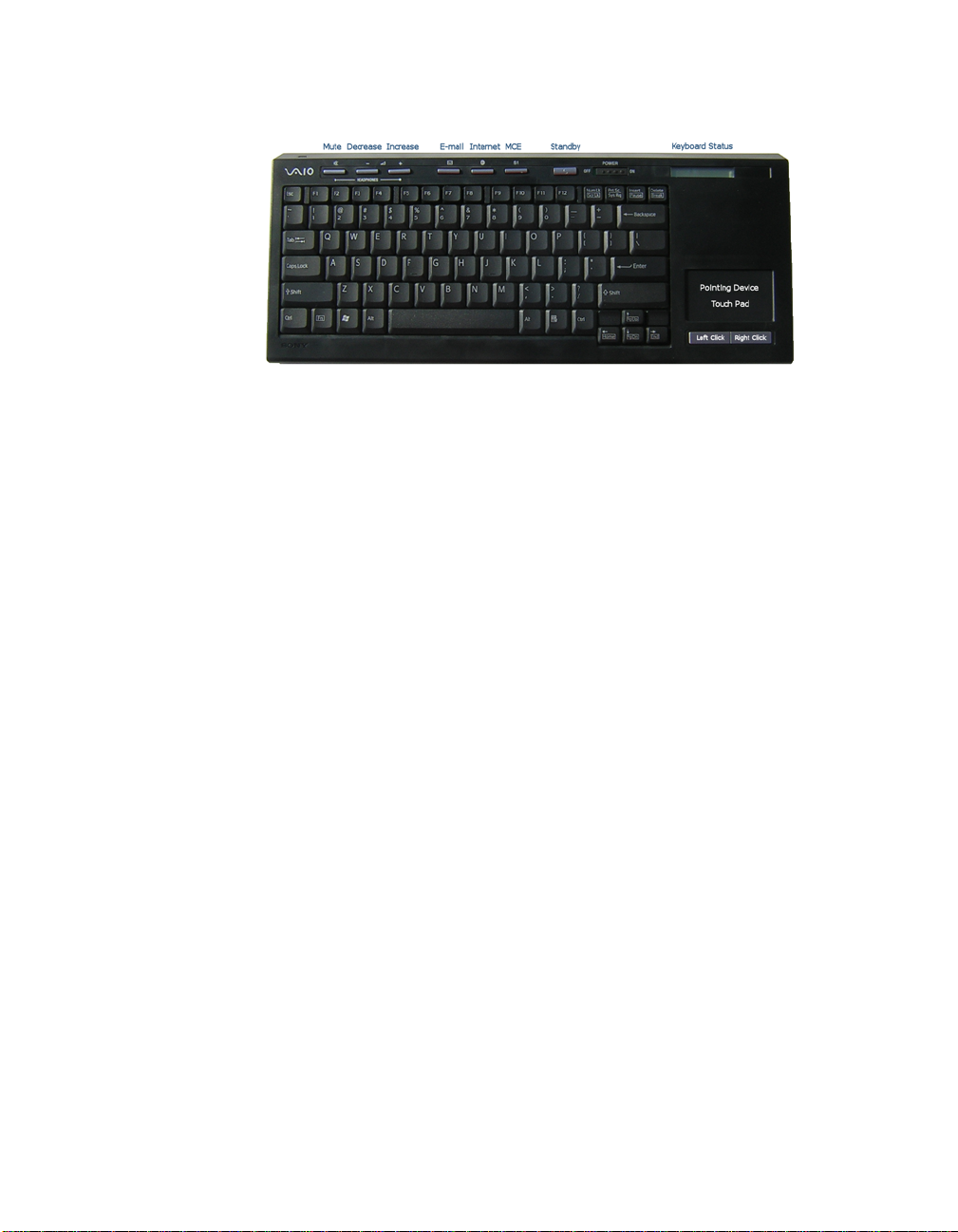
Wireless Keyboard
Setting up the Keyboard
Insert the Batteries
On the back of the Keyboard, remove the battery compartment cover and
insert four (4) Alkaline AA batteries (supplied) oriented as shown in the
battery compartment. Replace the battery compartment cover.
Activate Wireless Keyboard Communication
Before using the keyboard, you must activate communications between the
DLS computer and the wireless keyboard w/integrated pointing device.
To activate wireless keyboard communications
Make sure there are no obstructions between the XL2A computer and the
wireless keyboard when activating communications.
1 On the front of the keyboard, slide the Power button to On.
2 On the back of the keyboard, slide the Point Device button to On.
3 On the back of the keyboard, and the front panel of the XL2A compu ter, press
the connect buttons simultaneously and hold for a few seconds.
4 Test the keyboard and the point device to make sure both are functioning
properly.
6 VGX-XL2A Digital Living System
Page 10
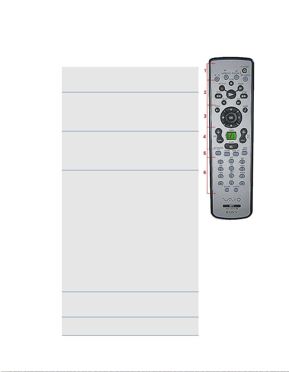
VAIO® Remote Control
Setting Up the Remote Control
1 Start MY TV, MY MUSIC, MY PICTURES, MY
VIDEO in Media Center. Press STANDBY to
place your computer in Standby mode.
2 Control the playback for TV, MUSIC, VIDEOS,
and ends a slide show. Buttons include:
STOP, PAUSE, FWD, SKIP, REPLAY, REW,
and RECORD. The right arrow button serves
as a PLAY button.
3 Use the arrow buttons to move to a specific
location, the OK button to make your
selection, the BACK button to go to the
previous screen, and the MORE button to
view additional information.
4 Use the START button to open Media Center.
Volume Controls (VOL) are on the left and
Channel (CH) or Page (PG) on the right of
the START button. A MUTE butt on is also
provided to suppress sound.
Follow the steps below to preset the MCE
remote control for TV volume.
1 Locate the input code number by
selecting your specific manufacturer.
MCE (RC6) Default: 01
Sony: 02
Samsung: 03,05,06,08,11 or 13
Toshiba: 07 or 09
Panasonic: 04 or 10
Sharp: 07 or 12
2 On the remote control, press and hold the
OK button. Then type the input code no.
5 Open the following screens RECORDED TV,
GUIDE, LIVE TV, DVD MENU. (DVD MENU is
available only when Media Center is active.)
6 Use these buttons to change channels and
enter text or numbers in a specific location.
VGX-XL2A Digital Living System 7
Page 11

Insert the Batteries
On the back of the remote control, remove the battery compartment cover and
insert two (2) Sony Super Manganese Alkaline batteries (supplied) oriented
as shown in the battery compartment. Replace the battery compartment
cover.
Note: When using the V AIO® remote control, remember to point the remote at
the VGX-XL2A personal computer, not at the TV or monitor.
About the Keyboard and Remote Control Batteries
When replacing batteries, the remote and keyboard will use any alkaline
batteries. Please use the "same” kind of new batter i es fr om the sam e
“manufacturer." Mixing new batteries and used batteries, and mixing different
kinds of batteries (combination of manganese batteries and alkaline batteri es,
etc.) can cause "leaking and damage".
Help Hints
• Turn the POWER switch "OFF" if you will not be using the keyboard for a
while. Also, please take the batteries out if you will not be using the
keyboard for a long time.
• The capacity of the batteries in the keyboard can be checked using the
battery indicator located on the upper right of the keyboard.
• Replace the batteries when they get low. If you leave the batteries in the
device even when the batteries are dead, it may cause leaking.
• Replace with new batteries after cleaning the liquid when liqui d leaks from
the batteries.
• Use regular batteries. Re-chargeable batteries are not supported.
• Use alkaline batteries for the keyboard.
8 VGX-XL2A Digital Living System
Page 12
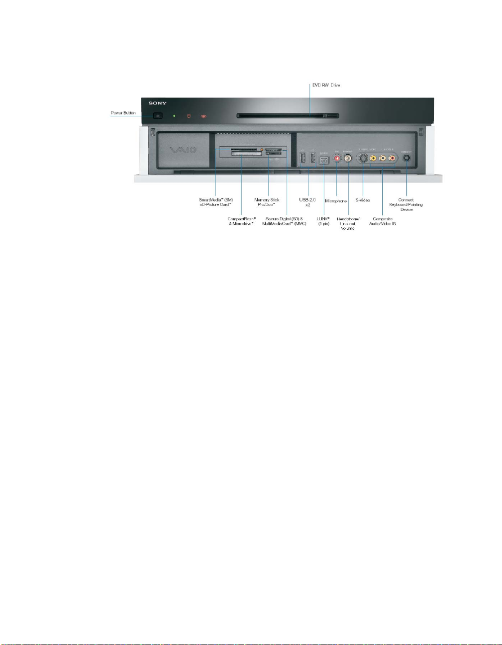
XL2A Personal Computer Front Panel
The XL2A Personal Computer Front Inputs and Outputs
Power Button
Press to turn on the power to this device. If you press this button during the
operation of this device, it will enter a hibernation state and the power lamp
will be turned off
Power Lamp
The power lamp turns green when the electric power to this device is turned
on. The power lamp blinks orange when it is in Away mode, and turn orange
when it is in Standby mode.
(Hard Disk) Access Lamp
The access lamp blinks orange when you read or write dat a by acce ssing the
disc or hard disc.
WLAN (wireless Lan lamp
The wireless LAN lamp turns green when the wireless LAN1 is ready to be
used.
DVD-RW Combo Drive (Double layer reco rding capable)
It will read data from DVD-ROM, DVD+R DL, DVD+R, DVD+RW, DVD-R
DVD-RW, CD-ROM, CD-R, CD-RW and write data to DVD+R DL, DVD+R
DVD+RW, DVD-R, DVD-RW, CD-R, CD-RW.
VGX-XL2A Digital Living System 9
2
Page 13

Eject button
Press when the disc is to be removed from the drive.
SmartMedia™ (SM) xD-Picture Card™ memory card reader
Reads and writes data from and to SmartMedia or xD-Picture Card media.
Memory card access Lamp
It blinks orange when you read or write data from a "Memory Stick®", xDPicture Card, Smart Media, Compact Flash, or SD memory card.
CompactFlash® & Microdrive™ memory card reader
Reads and writes data from and to CompactFlash and Microdrive media.
Memory Stick Pro™/Memory St ick Duo™
Data from the "Memory Stick®" is read and written.
Secure Digital (SD) & MultiMediaCard™ (MMC) memory card reader
Data from the SD memory card is read and written.
USB (Universial Serial Bus) Connector (x2)
Connects to a device which supports the USB standard.
The connector supports the USB 2.0 standard an d can also be connected to
a device which supports the USB 1.1 standard.
i.LINK
S400 port (IEEE 1394 connector (4 pin)
3
®
Connects to an i.LINK® supported device.
S-VIDEO (S video input)
Connection for an S-Video cable.
Composite Audio/Video IN
Connection for an Audio/Video cables.
Connect Keyboard/Pointing Device
Use this button when activating the wireless keyboard/pointing device.
1. Requires compatible wireless access point(s). Some features may rely on
Internet services which may require a fee.
2. DVD Media/Formats are not universally compatible.
10 VGX-XL2A Digital Living System
Page 14

3. i.LINK is a trademark of Sony used only to designate that a product contains an IEEE1394 connection. The i.LINK connection may vary depending on the software applications, operating system and compatible i.LINK
devices. All products with an i.LINK connection may not communicate with
each other. Please refer to the documentation that comes with any device
having an i.LINK connection for information on compatibility, operating
conditions and proper connection. For information on any Sony device
having an i.LINK connection, contact Sony at 1-800-686-7669.
Using Memory Cards and Memory Card Readers
This section provides basic information about using your computer’s installed
memory card readers and includes the following information:
• About Your Memory Card Readers
• About Memory Stick® Media
• Inserting a Memory Card
• Removing a Memory Card
• Sharing Memory Cards
About Your Memory Card Reader
Your VAIO® computer is equipped with memory card readers that are
compatible with many popular types of memory cards. You can use your
computer’s memory card readers to transfer data between digital cameras,
camcorders, music players, and other audio/video devices.
VGX-XL2A Digital Living System 11
Page 15
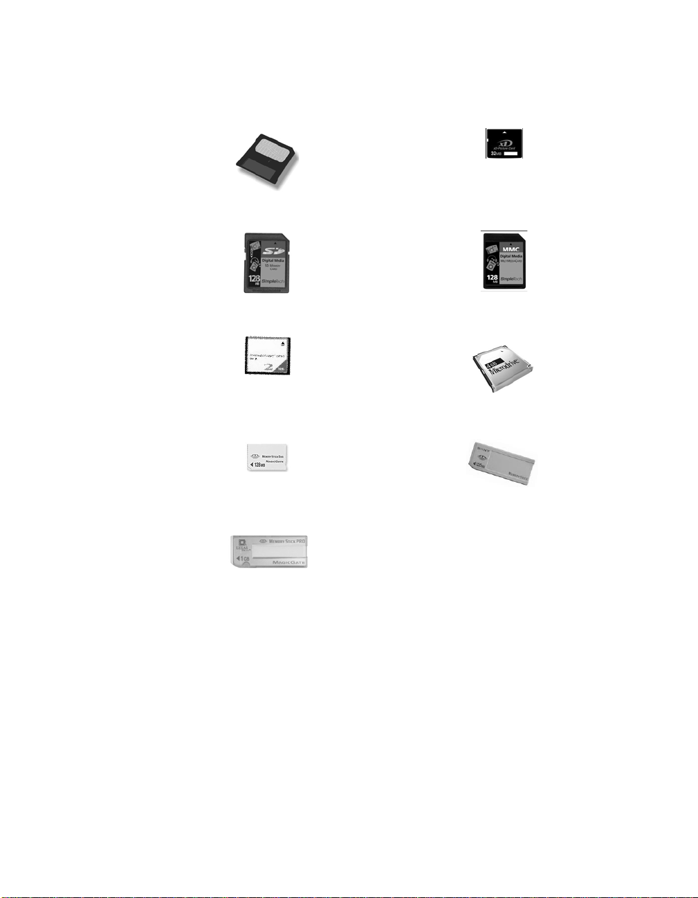
Supported Memory Card Readers and Compatible Media
Smart Media™ xD-Picture Card™
Secure Digital (SD) MultiMediaCard™
Compact Flash
®
Memory Stick Duo™
Memory Stick Pro™
Microdrive™
Memory Stick
®
12 VGX-XL2A Digital Living System
Page 16

About Memory Stick Media
Memory Stick® media are a compact, portable, and versatile data storage
media designed for exchanging and sharing digital data with compatible
devices. The following types of Memory Stick
compatibility with your computer can vary.
®
media are available, but
• MagicGate™ Memory Stick® Media - Provides copyright protection with
authentication and encryption, using Sony
®
MagicGate technology.
Authentication ensures that protecte d con te n t is only tra n sfe rr ed betwe en
compliant devices and media. Protected content can be recorded and
transferred in an encrypted format that prevents unauthorized duplication
or playback. You can store different data formats on a single Memory Stick
media.
• Memory Stick Pro™ media - Provides MagicGate copyright protec tio n
and high-speed data transfer features when used with comp atible Memory
Stick PRO devices. VAIO
®
computers support Memory Stick PRO media
for data storage purposes only. High-speed data transfer and MagicGate
technology features, such as authentication and encryption, may not be
available. You can store different data formats on a single Memory Stick
media.
• Memory Stick Pro Duo™ media - Provides the same features and
benefits of Memory Stick PRO™ media, in a form that is 1/3 smaller in
size.
• Memory Stick® media - Provides data storage only. The Memory Stick
media does not provide MagicGate technology or high-speed data
transfer. You can store di fferent data formats on a single Memory Stick
media.
• Memory Stick Duo™ media - Provides the same features and bene fits of
MagicGate™ Memory Stick media, in a form that is 1/3 smaller in size.
Compatibility between software programs and Memory Stick® media formats
may vary. At this time, Sony suggests using only MagicGate Memory Stick
®
media to store and transfer any data created with SonicStage
software.
Visit the Sony online support Web site at http://www.sony.com/pcsupport
®
regularly for the latest information on Memory Stick
media.
Note: Memory Stick media do not support AVI file playback directly from the
media. Copy the video file to your hard disk drive and then play back the file.
VGX-XL2A Digital Living System 13
Page 17
Inserting a Memory Card
The memory card reader(s) are located be hind a protective cover on the front
of the computer. To access the Memory Card Readers, flip the front cover
down.
To insert Memory Cards
1 From the front panel, locate the appropriate reader(s) for the memory card(s)
you want to use.
2 Insert the memory card into the reader, in the direction indicated of the arrow
on the media. Do not force the card into the reader.
Note: If the memory card does not go in easily, gently remove the card and
verify you are entering the card in the proper di r ect ion.
To Protect data on Memory Stick® Media
Some Memory Stick® media are equipped with a write-protect tab*. The write
protect tab prevents accidental changes to information recorded on your
Memory Stick me dia. When you slide the write-protect tab to the LOCK
position, your Memory Stick
copy, or save information on the media while the write-protect tab in the
LOCK position. When you slide the tab to the un-LOCK position, you can
write to or modify your Memory Stick media’s contents.
®
media is write-protected. You cannot delete,
Locking the Memory Stick
®
If your computer stops recognizing your Memory Stick® media, you may have
removed the media from the Memory Stick drive before the data access
process completed. If this occurs, follow these steps:
1 Remove the Memory Stick® media from the slot.
2 Shut down your computer , closing any open soft ware programs, and then turn
your computer off.
3 Wait approximately 30 seconds, and then restart yo ur computer.
Your computer recognizes the Memory Stick® media, when you insert it into
the Memory Stick slot again.
14 VGX-XL2A Digital Living System
Page 18

Removing a Memory Card
The correct way to remove a memory card from a memory card reader varies,
depending upon the media, reader, or computer model. Use care when
removing a memory card to avoid damage to the reader or card.
Note: Do not remove a media card while the media access indicator light is
on. The card or its data may be damaged.
To remove a Memory Stick® media, Secure Digital (SD),
MultiMediaCard™, SmartMedia™, or xD-Picture Card™ media
1 Press the extended part of the memory card, cau sing it to extend out from the
reader’s slot.
2 When the card extends, carefully remove it.
To remove a CompactFlash® media†
1 Firmly grasp the extended part of the memory card.
2 Pull to remove from the reader.
Sharing Memory Cards
If you plan to share your memory card between your VAIO® computer and
devices such as a digital camera or music player, the card must be formatted
properly. Follow the steps below to format your memory card.
1 Format the memory card by using it in the device first. See the information
supplied with the device for details how to format the memory card.
2 If your device does not recognize memory card that has been formatted by
your computer, so the following:
• Save the card’s contents to your hard disk drive.
• Reformat the memory card using the device, not your computer.
VGX-XL2A Digital Living System 15
Page 19
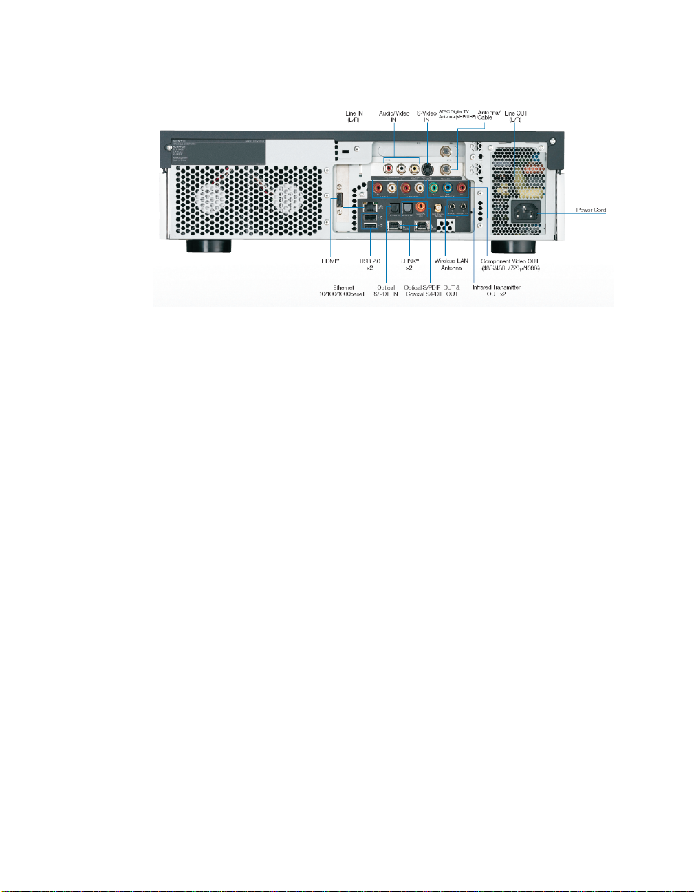
XL2A Personal Computer Back Panel
The XL2A Personal Computer Back Inputs and Outputs
Line IN (L/R)
Connection for an external device.
Audio/Video IN
Connection for an Audio/Video cable to bring signal to the XL2A computer.
S-Video IN
Connection for an S Video cable.
ATSC Digital TV Antenna (VHF / UHF)
Connection for over-the-air digital antenna.
Antenna/Cable
Connection for cable provider or external antenna.
Line OUT (L/R)
Connection for an external device.
HDMI™
Connection for HDMI cable for high definition video and/or sound for TV.
Ethernet 10/100/1000baseT
Connection for a 10BASE-T/100BASE-TX/1000BASE-T Ethernet.
(The port marked with the Network symbol is for LAN connections only.)
16 VGX-XL2A Digital Living System
Page 20

USB 2.0 (x2) Universal Serial Bus
Connects to a device which supports the USB standard.
The connector supports the USB 2.0 standard an d can also be connected to
a device which supports the USB 1.1 standard.
Optical S/PDIF IN
Connection for Audio In.
1
®
i.LINK
(x2)
Your VAIO® computer is equipped with one 4-pin (front panel) and two 6-pin
(back panel) i.LINK
connected i.LINK
to a connected i.LINK
®
ports. A 4-pin i.LINK port cannot supply power to a
®
device. A 6-pin i.LINK port can supply power (10V to 12V)
®
device, if the device is equipped with a 6-pin
connector.
Optical S/PDIF OUT & Coaxial S/PDIF OUT
Connections for Audio Out.
Wireless LAN Antenna
Connection for Wireless LAN Antenna.
Infrared Transmitter OUT (x2)
Controls VCR, Setup box, and other devices in MCE.
Component Video OUT (480i, 480p,720p)
Connections for Video Out.
Power Cord
Connection for supplied power cord.
1. i.LINK is a trademark of Sony used only to designate that a product contains an IEEE1394 connection. The i.LINK connection may vary depending on the software applications, operating system and compatible i.LINK
devices. All products with an i.LINK connection may not communicate with
each other. Please refer to the documentation that comes with any device
having an i.LINK connection for information on compatibility, operating
conditions and proper connection. For information on any Sony device
having an i.LINK connection, contact Sony at 1-800-686-7669.
VGX-XL2A Digital Living System 17
Page 21
Support Resources.
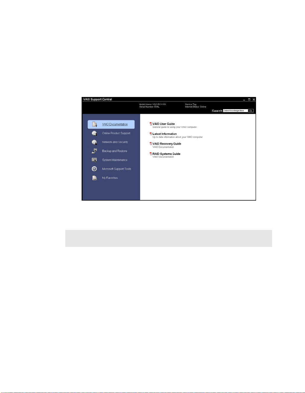
VAIO® Support Central
VAIO® Support Central provides you with a single location for all of your
support needs and allows you to easily access valuable suppo rt and technical
information from Sony and Microsoft.
Keep your VAIO® computer’s system software and operating system updated
using VAIO Web Support and Microsoft Update.
Note: You must be connected to the Internet to access some of the VAIO
Support Central features.
Please carefully review all support options in VAIO Support Central.
18 VGX-XL2A Digital Living System
Page 22

To access VAIO® Support Central
1 Using your wireless keyboard w/integrated pointing device, select the
Windows Start button.
2 From the Start menu, select All Programs.
3 From the All Programs menu, select VAIO® Support Central.
Note: To access the most updated information available for the VGX-XL2A
Digital Living System, periodically go to VAIO
Documentation and select the VGX-XL2A DLS User Guide. This guide will
updated on an ongoing basis for your convenience.
®
Support Central >
Documentation
The following support documents for the VAIO® VGX-XL2A Digital Living
System™ are available in VAIO
Online User Guide: The online user guide is designed to provide you with
detailed information about the VGX-XL2A Digital Living System™ product.
Note: The Online User Guide will be updated on an ongoing basis for your
convenience. Please return to VAIO Support Central > Documentation
periodically to download updated User Guide information.
®
Support Central.
Safety Information
Carefully read the VGX-XL2A Safety Information Guide. The guide, in printed
format, is contained in the packaging materials and can also be access from
VAIO Support Central by selecting Documentation.
VGX-XL2A Digital Living System 19
Page 23

Additional Notes
The wireless LAN function
The wireless LAN1 that comes equipped in this device is certified to comply
with the "Wi-Fi specifications" under the provisions of the WFA (Wi-Fi
Alliance.)
Security when using wireless LAN devices
It is very important to set up security on the wireless LAN.
Important Note: Sony will not be held responsible for damages resulting
when security measures are not taken, or when security problems occur due
to the circumstance outside of the wireless LAN specifications.
Refer to Appendix A: Wireless Local Area Network in this guide for more
details.
Copy protection
You can not use this device for recording of content for other than your
personal enjoyment without the copyright holders permission under the
copyright law.
It is necessary to obey the copyright law and permitted usage conditions for
each copyrighted work and for making multiple copies of copyrighted wor ks. It
is prohibited to make copies or use, chan ge, delete or make other revisions to
or alter the integrity of captured video, images, or audio without the copyright
owners permission.
Summary
Chapter 1: Getting Started provided you with an overview of the VGX-XL2A
Digital Living System™ including hardware, operating system, and additional
value-added VAIO
1. Requires compatible wireless access point(s). Some features may rely on
Internet services which may require a fee.
20 VGX-XL2A Digital Living System
®
software.
Page 24

Before You Begin
Before setting up your VGX-XL2A Digital Living System™, consider the
environment in which it will be placed. Listed bel ow are som e gene ra l
guidelines.
• The maximum distance between XL2A computer and the keyb oard can be
up to 30 ft.
• Placing the keyboard near a metallic object may affect communication
between the keyboard and the computer.
• Do not set up the VGX-XL2A DLS in the following locations:
- in direct sunlight
- near a magnet or a item that generates a magnetic field
- areas with high heat, such as near a heater
- areas with excessive heat, dust, and humidity
- areas with poor ventilation
Please observe the following items to avoid damage.
• Always turn off the power before the device is moved. Damage may be
caused to the hard disk if the device is transferred or moved with the
power on.
Chapter 2:
Setting Up the DLS System
• Do not tip or hit this device. Even a small impact or vibration may cause
some damage to your hard disk.
• Do not set up where it is not secure.
• Do not place an object over the ventilation holes.
• If the XL2A computer is placed in an enclosed ent er tainmen t cab in et ,
make sure there is sufficient airflow.
VGX-XL2A Digital Living System 21
Page 25

Step 1: Connecting the XL2A Computer and a CD/
DVD Changer/Recorder
If you have purchased a CD/DVD changer, connecting the changer to the
computer is a simple process requiring only a single cable.
1
Using the supplied i.LINK
i.LINK® connector on the back panel of the XL2A computer, and the end with
the node to an i.LINK
®
cable, connect the end without the node to an
®
connector on the back panel of the changer.
Step 2: Connecting your TV
You can receive analog and digital TV signal transmissions using with the
following connections:
HDMI™ Connector
If your TV has a HDMI™ connector, use the supplied HDMI™ cable and
connect one end to your TV and the other end to the HDMI™ c on nec t or on
the back panel of the DLS computer.
DVI-D Connector
If your TV has a DVI-D connector, use the supplie d HDMI cable and the
HDMI™ to DVI-D adapter . Insert the ada pter into the DVI-D TV/monitor. Then
using the supplied HDMI™ cable, connect one end of the cable to the adapter
and the other end to the HDMI™ connector on the back panel of the XL2A
computer.
Component Connectors (Y, Pb, Pr)
If your TV has component connectors, use a component video cable (not
supplied) and connect one end to the corresponding video o utputs on your TV
and on the back panel of the XL2A comput er. In this type of connection, there
will be separate audio connections.
1. i.LINK is a trademark of Sony used only to designate that a product contains an
IEEE1394 connection. The i.LINK connection may vary depending on the soft
ware applications, operating system and compatible i.LINK devices. All products with an i.LINK connection may not communicate with each other. Please
refer to the documentation that comes with any device having an i.LINK con
nection for information on compatibility, operating conditions and proper connection. For information on any Sony device having an i.LINK connection,
contact Sony at 1-800-686-7669.
22 VGX-XL2A Digital Living System
-
-
Page 26

Additional Notes:
• If your TV has a HDMI™ connector and a DVI-D connector, Sony
recommends using the HDMI™ connector.
• The HDMI cable carries both video and audio s ign a ls.
• You cannot use HDMI™ and Component Video connections at the same
time.
• If device drivers other than the ones provided by Sony are used, the image
may not be displayed and the audio may not be heard. Always use the
device driver provided by Sony for any updates.
• You can connect the HDMI™ out to an A/V receiver/amp and audio will be
heard through the AV amp and then another HDMI™ cable can be con
nected from the AV amp to the TV for the display. (Some protected video
content may not display with this type of connection. A direct connection is
advised.)
-
VHF/UHF Connector (for Receiving Digital TV Transmission
If you have an antenna for receiving the over-the-air signals transmitted by a
digital TV broadcasting system, you can connect it to receive these signals for
digital televisions, for example high definition TVs. Refer to the “ Connecting to
an Antenna (air) for Digital Television System (ATSC Signal Standard)” in the
next section for more information.
Additional TV Connections
Note: Your VAIO® XL2A computer is supplied with certain video cables.
Depending on your in home cable access, you may require extra cables,
adapters or connection equipment not supplied with your computer.
Connecting to standard cable access (CATV)
Option 1
1 Connect one end of the TV coaxial cable (optional) to your cable service
access.
VGX-XL2A Digital Living System 23
Page 27
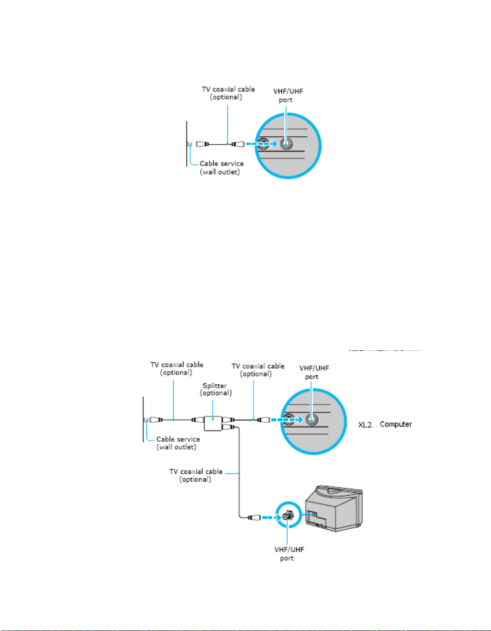
2 Connect the other end of the TV coaxial cable to the VHF/UHF port on the
back panel of your computer.
Option 2
1 Connect one end of a TV coaxial cable to your cable service access. Connect
the other end to the single-connection side of a splitter adapter.
2 Connect a second TV coaxial cable (optional) to the double-connection side
of the splitter adapter. Connect the other end to the VHF/UHF port on the
back panel of your computer.
3 Connect a third TV coaxial cable (optional) to the double-connection side of
the splitter adapter. Connect the other end to the VHF/UHF port on the back
of your TV monitor or display.
24 VGX-XL2A Digital Living System
Page 28
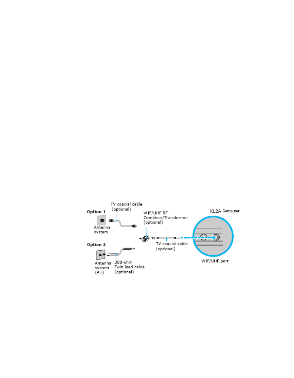
Connecting to a Standard Antenna (air) System
You can connect your computer to an indoor/outdoor antenna system, using
Option 1 or 2 from the previous section, “Connecting to standard cable access
(CATV).” The antenna system in your home may require a VHF/UHF RF
combiner/transformer (optional) to connect your computer and the indoor/
outdoor antenna system.
Option 1
1 Connect one end of a TV coaxial cable (optional) to your antenna outlet.
Connect the other end to a VHF/UHF RF combiner/transformer (optional).
2 Connect a second TV coaxial cable (optional) from the combiner/transformer
to the VHF/UHF port on the back panel of the XL2A Computer.
Option 2
1 Connect both ends of the antenna’s twin lead cable to the screw-type grip s on
the combiner/transformer.
2 Connect the TV coaxial cable (optional) from the combiner/transformer to the
VHF/UHF port on the back panel of your computer.
If you are connecting to an indoor/outdoor antenna system, you may need to
re-orient the antenna for better reception.
VGX-XL2A Digital Living System 25
Page 29
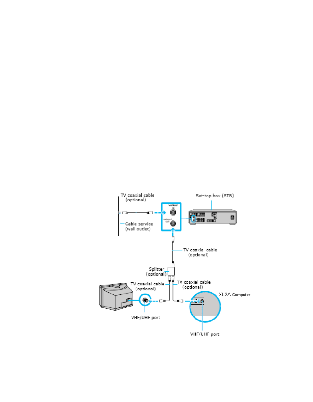
Connecting a Cable or Satellite Set-top Box
You can connect your computer to cable or satellite service that requires a
set-top box.
Option 1
1 Connect one end of a TV coaxial cable (optional) to your cable service
access. Connect the other end to the In jack on the back panel of your set-top
box.
2 Connect a second TV coaxial cable (optional) to the Out jack on your set-top
box. Connect the other end to the single-connection end of a splitter adapter
(optional).
3 Connect a third TV coaxial cable (optional) to the double-connection end of
the splitter adapter. Connect the other end to the VHF/UHF port on the back
panel of your computer.
4 Connect a fourth TV coaxial cable (optional) to the double-connection end of
the splitter adapter. Conn ect the other end to the VHF/UHF port on the rear of
your TV monitor or display.
26 VGX-XL2A Digital Living System
Page 30
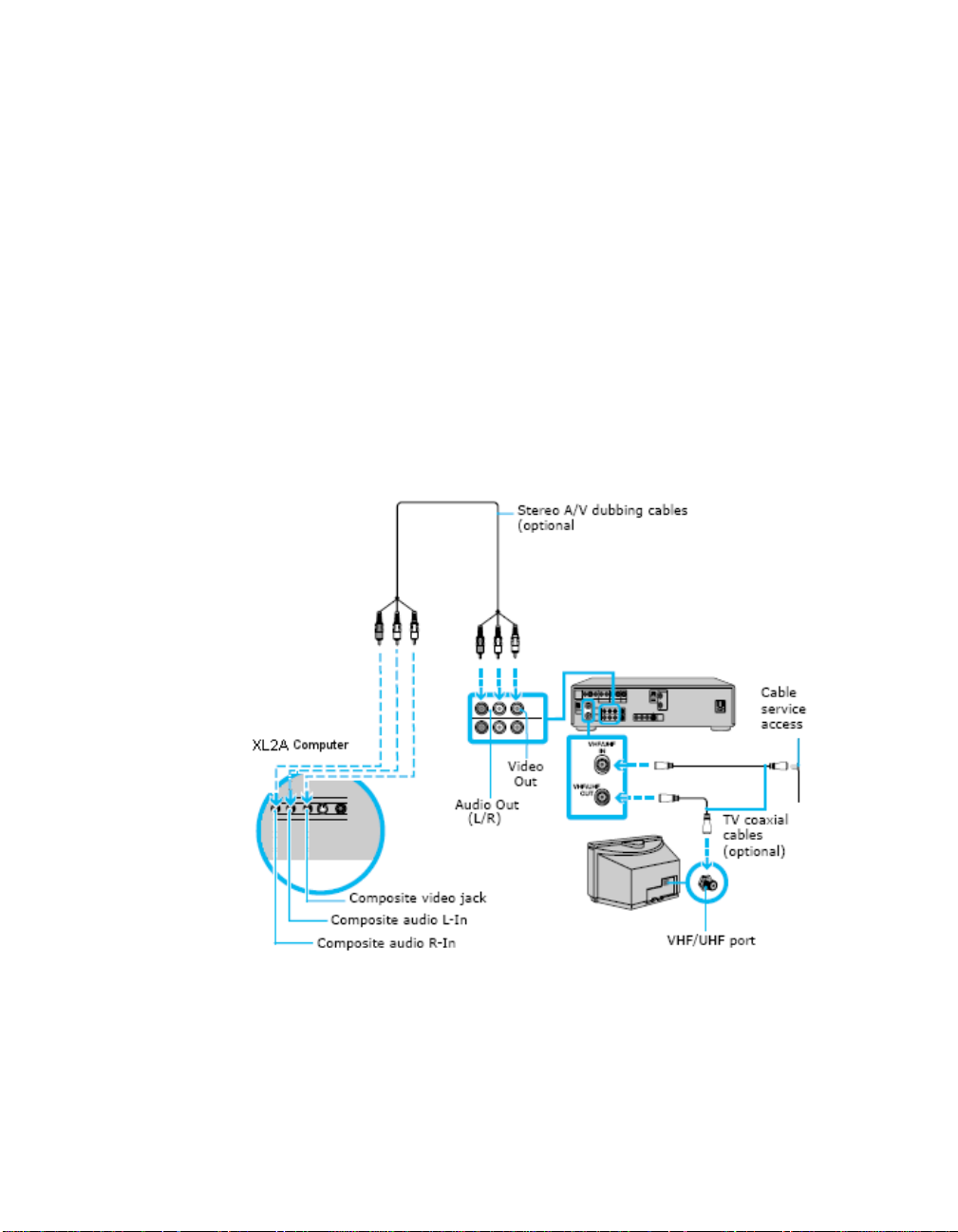
Option 2
1 Connect one end of the TV coaxial cable (optional) to your cable service
access. Connect the other end to the In jack on the back panel of your set-top
box.
2 Connect a second TV coaxial cable (optional) to the Out jack on your set-top
box. Connect the other end to the VHF/UHF port on the rear of your TV
monitor or display.
3 Connect one end of a stereo A/V dubbing cable with triple RCA plugs
(optional) to the Video-Out and Audio-OUT (L/R) jacks on the back panel of
your set-top box, matching the plug and jack colors.
4 Connect the other ends of the stereo A/V dubbing cable into the Audio Input-
L, Audio Input-R, and Video Input jacks on the back panel of yo ur computer,
matching the plug and jack colors.
VGX-XL2A Digital Living System 27
Page 31

Connecting to an Antenna (air) for Digital T elevision System (ATSC Signal Standard)
You can connect to receive over-the-air signals that meet the The Advanced
Television Systems Committee (ATSC) Signal standard intended for digital
televisions, for example high definition TV s.
ATSC is the group that helped to develop the new digital television standard
for the United States and other countries. It is intended to replace the earlier
analog-type television system standard and produce wide screen 16:9 images
up to 1920×1080 pixels in size—more than six times the display resolution of
the analog standard. However, a host of different image sizes are supported,
so up to six standard-definition “virtual channels” can be carried in a single
broadcast. ATSC also boasts “theater quality" audio because it uses the
Dolby Digital (AC-3) format to provide "5.1" surround sound. Numerous
auxiliary data services can also be provided.
The ATSC system supports a host of different display resolutions and frame
rates.The formats below list fthe supported rame/field rates and lines of
resolution:
• Stan dard Definition television (SDTV): 480i60, 480p24, 480p30, 576i50,
576p25
• Enhanced-definition Television (EDTV): 480p60, 576p50
• High-definition television (HDTV): 720i50, 720i60, 720p24, 720p25,
720p30, 720p50, 720p60, 1080i50, 1080i60, 1 080p24, 1080 p25, 1080p30.
28 VGX-XL2A Digital Living System
Page 32

Refer to Appndix C for setting up digital TV functionality using Microsoft®
Media Center.
Step 3:Connecting your Home Theater / Speakers
Two-channel sound system
If your sound system has two channels, use the LINE OUT (L) (R) on the back
panel of the DLS computer and the LINE IN composite audio connectors on
your speakers/receiver.
More than two-channel sound system
If your sound system has more than two channels, use the supplied optical S/
PDIF cable and connect one end to the S/PDIF OPTICAL OUT connector on
the back panel of the DLS computer and the other end to the OPTICAL IN
connector on your sound system. You can also use a coaxial S/PDIF
connection when connecting a multi-channel sound system.
Additional Notes
• An optical/coaxial connection will provide a higher quality output than a
composite connection.
Configuring software for your speaker system
When using a multiple channel speaker system, certain software programs
require setting changes to make certain you have proper audio performance.
Your computer's factory default settings for audio can be changed using the
Media Center Settings feature. You can switch between 2-channel, 6-chan nel,
or S/PDIF output modes.
VGX-XL2A Digital Living System 29
Page 33

To change speaker settings, do the following:
This procedure will demonstrate how to set up 5.1 surround sound speakers.
Your selections may differ depending on your type of speakers.
1 From the Media Center Start menu, select Settings > General > Media
Center Setup, Set Up Your Speakers.
The Speaker Setup screen displays.
2 Select Next. The Choose number of speakers screen displays.
3 Select 5.1 surround speakers. The Speaker Connection Type screen
displays.
30 VGX-XL2A Digital Living System
Page 34

4 Select the appropriate connection type. Your selection depends on the type of
cable used to connect your 5.1 surround sound speakers. Select Single RCA
(digital) for coaxial S/PDIF or Toslink (digital) for optical S/PDIF and HDMI.
5 Select Next.
6 From the Test Your Speakers screen, select the Test button. The system will
test your speakers for sound.
Important: Then select I heard sound from all my speakers, even if you did
not hear sound from all your speakers. The You Are Done! screen displays.
7 Select Finish.
VGX-XL2A Digital Living System 31
Page 35

8 Return to the Media Center Start menu and select Settings > DVD > Audio.
InterVideo opens and displays the Welcome to Audio Settings screen.
9 Select Configuration. The Speaker Configuration screen displays.
10 Verify that Analog - 5.1 Channel displays in the Set sound output to match
your system text box. Select Save and close Media Center.
Note: Even if you are using a S/PDIF connection, ALWAYS choose Analog -
5.1 Channel. DO NOT SELECT S/PDIF.
To complete Speaker Setup, go to the Windows Control Panel.
1 Open the Control Panel. Select Windows Start > Control Panel.
2 From the Category view, select Sounds, Speech, and Audio Devices.
32 VGX-XL2A Digital Living System
Page 36

3 From the Sounds, Speech, and Audio Devices screen, select Sound
Reality™ Audio from the Pick a Control Panel icon section. The Sound
Reality Control panel displays.
4 Select the Advanced tab.
5 From the S/PDIF group box:
• Check the Enable Dolby® Digital Live check box.
VGX-XL2A Digital Living System 33
Page 37

• Verify that AC3 is the option selected for Format.
• Verify that Enable Digital Output is checked in the S/PDIF group box.
Note: If you are using a HDMI connection through a TV or an amplifier that
supports 5.1 sound, do the following:
• check Enable HDMI™ Output
•select AC3 for the format
• check Enable Digital Output
6 Close the Sound Reality Control Panel and the Windows Control Panel.
Your 5.1 Surround Sound Speaker Setup is complete.
Speaker Setup Notes
• After the 5.1 channel sound is setup, sound may not be outputted through
the HDMI connection if your HDMI device does not support 5.1 channel
sound. To enable HDMI sound, uncheck the Enable Dolby Digital Live
check box and check/select the Enable HDMI Output check box located
on the Sound Reality Control Panel, Advanced tab. This will disable the
5.1 channel sound output.
• Dolby Digital 5.1 must be selected for the audio output of the DVD from the
DVD menu. Note: The VGX-XL2A does not support DTS sound decoding.
Step 4: Connecting to the Internet
Wired Net work
Use an RJ-45 connector cable. Connect one end to the Ethernet co nnector on
the computer and the other end to your cable or DSL modem.
34 VGX-XL2A Digital Living System
Page 38

Wireless Network
Connect the WLAN antenna (included) to the connector on the back pa nel of
the XL2A computer.
For better reception, if needed, you m ay mount the wireless LAN ante nna to a
wall using the included screws.
Launch the Marvell® Client Utility Application. Click the Windows Start button.
Then select All Programs > Marvell
®
Wireless SoftAP . Select Station as the
operation mode. Then proceed to Windows Wireless Zero Configuration
service to set up your connection with your preferred Access Point. For
additional information about setting up a wireless LAN, go to Appendix A.
VGX-XL2A Digital Living System 35
Page 39

Step 5: Turning Power On
Make sure all hardware is connected and that power cables are plugged into
properly grounded electrical outlets (three pronged outlets).
Turn on the power to the computer, TV, and speakers.
Activate Wireless Keyboard Communication
1 From the front of the keyboard, slide the Power button to On.
2 From the back of the keyboard, slide the Pointing Device button to On.
3 From the back of the keyboard, and the front panel of the XL2A comp u ter,
press the Connect buttons simultaneously and hold for a few seconds.
4 Test the keyboard to make sure it is functioning properly.
Step 6: Software Setup
Microsoft Windows operating system setup
The first time you start your computer your will be presented with a series of
screens for Microsoft
instructions.
Note: For information concerning Firewall, Automatic Updates, Virus
Protection, and other security related features of Microsoft Windows XP, see
the Windows Help file.
®
Windows® XP Setup. Please follow the on-screen
Sony Registration
After you complete Microsoft Windows operating system setup, a Sony
Registration screen automatically appears. Please complete all requested
information to register your Sony
Note: Registration can be done through the Internet. To r egister your product,
go to http://www.esupport.sony.com and select Register from the menu bar.
Sony product registration is voluntary; failure to register will not diminish your
limited warranty rights.
Sony encourages you to complete the "VAIO customer registration" in order
for us to notify you with necessary information such as security information
and provide full service/support to the customer who owns the VAIO
®
product.
®
product.
36 VGX-XL2A Digital Living System
Page 40

Software Setup Notes
• If Media Center automatically opens, and yo u ne ed to ad jus t you r pic tu re
quality, minimize Media Center and go to Step 7: Resolution Setup. When
complete return to Media Center.
• Make sure your Internet connection is working properly.
• Media Center Setup: The first time Media Center starts, you will be
presented with a series of screens that will guide you through Media
Center Setup. Please follow all on-screen instructions.
• Media Center Wireless Network: If you have an existing wireless network,
and you wish to add the XL2A computer to the n etwork, start Media Center
and from Settings, go to General > Media Center Setup > Join Wireless
Network. Then follow all on-screen instructions.
Step 7: Resolution Setup
To set the resolution for your TV or monitor, do the following:
1 Using the pointing device on your wireless keyboard, right click anywhere on
the Windows desktop.
2 From the menu, point to or click NVIDIA® Display . A new me nu option opens.
The menu option name depends on what TV or monitor is connected to the
computer.
VGX-XL2A Digital Living System 37
Page 41

3 Click the appropriate display. The following screen displays.
4 From the Directory list, click nView Display Settings, if necessary.
5 Click the Device Settings button.
6 From the side menu, click TV Format and select the appropriate option for
your TV from the list.
7 Continue with Media Center Setup.
Setting Up a Local Area Network
For detailed information on setting up your Wireless LAN1, see Appendix A,
“Setting up a Wireless LAN.”
Wired Network
Use an RJ-45 connector cable. Connect one end to the Ethernet co nnector on
the DLS computer and the other end to your cabl e or DSL mo de m .
1. Requires compatible wireless access point(s). Some features may rely on
Internet services which may require a fee."
38 VGX-XL2A Digital Living System
Page 42

Wireless Network
Wireless LAN removes all of the trouble of cable connections and helps to
build a wireless LAN (Local Area Network) environment. This device is
equipped with a 2.4 GHz wireless LAN Controller (IEEE802.11b/g compliant).
Turning the Power Off
Please follow the following procedure when turning the power off to the XL2A
computer.
1 Select the Windows Start button.
2 Select T urn Off Computer and then from the Turn Off Computer screen,
select Turn Off.
In a short time the power to the XL2A computer goes off automatically and the
power lamp goes off.
Note: If the power does not turn of f by this pro cedure, you can turn the power
off by holding down the Power button on th e XL2A computer for more than six
(6) seconds. WARNING: Any changes that have not been saved will be lost.
Power Saving Functions
The VGX-XL2A personal computer offers two power-saving function modes,
Stan dby and Hibernation, which are used to reduce power consumption whe n
not in use.
VGX-XL2A Digital Living System 39
Page 43

The table below list the characteristics of each function:
Standby Mode
Power Lamp Orange in color.
State Reduces power consumption because it turns off the
components other than the minimum compone nts
necessary while maintaining the current working
status.
Enter Standby
Mode
• Press the Power/Standby key on the keyboard.
• Click Standby in the Turn Off Computer screen,
which displays when selecting Start > Turn Off
Computer.
• Press the Standby button on the remote control.
Return to normal
operation
• Either press the Space key or the Power/Standby
key on the keyboard, or press the power button on
the front of this device.
• Press the Standby button on the remote control.
Hibernation State
Power Lamp Power lamp is off.
State Main power is turned off and the fan for the internal
main power section is paused. Saves the current
working status to the hard disk and turns off the
power for this device.
Enter Standby
Mode
• Press the power button on the front of this device.
• Click Hibernate in the Turn Off Computer screen,
which displays when selecting Start > Turn Off
Computer.
Return to normal
operation
•Press the Power button on the front of this device.
• Press the Power/Standby key on the keyboard.
Note: This device will not return to normal opera-
tion by remote control when in hibernation.
40 VGX-XL2A Digital Living System
Page 44

Summary
Chapter 2: Setting Up Your VGX-XL2A Digital Living System™ provided you
with step by step instruction about setting up the DLS system including the
operating software.
VGX-XL2A Digital Living System 41
Page 45

Hardware Upgrades & Maintenance
Adding Memory
Memory can be upgraded using the expansion memory slot inside this device .
Upgrading memory increases the data processing spe ed and allo ws fa ste r
response time when running multiple prog r am s at th e sa me time .
There are a total of 4 slots available in this device to install memory modules
and it can be upgraded to a total of 2 GB. Upgrade the memory by installing
memory modules sold separately.
Safety Information
Please read the following safety information before installing a memory
modules.
• Please be careful not to get cut by the parts or the circuit board inside this
device when installing the memory.
• Be careful not to catch your fingers on the cables inside this device and
remove or dislodge the cable when installing the memory.
Chapter 3:
• Turning the power on with a foreign object (metal, such as a screw) left
inside the device at the time of upgrading the memory may cause damage.
Always remove any foreign objects and replace the cover before tur ning
the power on.
• Don't touch the electronic components on the circu i t bo ar d of this de vice .
They are susceptible to pressure and static, which may cause a failure.
• Wait about one hour after turning off the power. The inside of this device
may be hot right after the power is turned off and may cause bu rns.
Please be careful when upgrading memory. Mishandling when installing and
removing can cause a failure of this device. You are encouraged to request
the installation be done by a dealer or professional.
VGX-XL2A Digital Living System 42
Page 46

If you upgrade the memory by yourself and forget to close the inside
connector, insert the me mory backward, or not completely seat the memory, a
failure or damage may result. Repair costs in these and similar situations will
be charged to the owner.
Contact customer support for questions about upgr ading the memory. The
Sony repair centers provide a service for charge for those who can't install the
memory by themselves and for people who pu rchased or plan to purchase
Sony memory.
Sony Supported Memory Types
The following Sony memory modules can be installed in this device:
Capacity Speed Memory Module
512 MB DDR2 533 (PC2-4200) VGP-MM512J
Important Note: Always use DDR2 533 SDRAM DIMM VGP-MM512J.
Memory Capacity After an Upgrade.
Using Standard Memory: DDR2 533(PC2-4200)
Standard Upgrade
Capacity Bank 0 Bank 1
St andard (1024MB) 512MB x 2 DDR2 533
43 VGX-XL2A Digital Living System
Page 47

Removing Standard Memory and upgrading to 512MB x 4
Standard Upgrade
Capacity Bank 0 Bank 1
2048MB 512MB x 2 DDR2 533 512MB x 2 DDR2 533
Note: Dual channel is a technology that doubles the memory bandwidth
capability to transfer 128 bits using two 64-bit wide channels for the DDR
memory interface. A total 128-bit wide dual channel DDR memory interface is
achieved by loading identical pairs of two DDR memory modules with the
same speed and the same capacity.
Precautions when selecting memory modules.
• There are various types of memory modules. Make sure that the products
purchased at a store have a written warranty for the device when
installing.
• Sony does not provide support for memory modules purchased at stores.
Consult with the dealer where you purchased the memory module with
questions.
Install Notes:
Observe the following when installing a memory module in order to not
damage the memory module with static.
• Do not work in a location where static builds up (such as on the carpet)
when upgrading the memory.
• Touch the metal in this device to discharge the static in your body first and
then proceed with the work.
• The memory module comes in a static protection bag. Do not take the
memory module out from the bag until right before installing.
• Do not touch the semiconductor chip or the connectors when you hold the
memory module.
• Cover the memory module with a static protection bag or aluminum foil to
store.
Please be careful of the following when upgrading the memory as the memory
slots for this device are separated into two banks.
VGX-XL2A Digital Living System 44
Page 48

• There are two banks and four slots (two in each bank) available to install
memory modules in this device. Each slot can hold a 512 MB memory
module.
• Install memory modules of the same type, name, speed, and capacity in
both slots in the same bank.
• Always install from bank 0 when installing memory modules.
• Also, refer to the memory module user's manual when installing.
• The memory modules have a proper direction.
• Properly match the notch area on the edge of the memory module
connector and the projections (inside the connector) in the slot.
• Please be careful not to forcefully insert the memory module in the slot in
the opposite direction which can cause damage to th e me m or y mo du le
and the slot or loosen it from the circuit board.
Install and remove memory modules
1 Turn off the power to this device and all peripheral devices, and remove the
power cord and all cables connecting peripheral devices. Some inside
components may be hot. Wait ap proximately one hour before proceeding to
work.
2 Remove the upper cover. Remove the screws at the rear and slide the cover
off.
45 VGX-XL2A Digital Living System
Page 49

3 Remove the graphic card. Remove the cable and screw first and remove the
graphic card while pressing the latch.
Remove screw
Press down
on latch
4 Touch metal to discharge any static buildup in your body and then remove the
memory module from of the package.
5 Carefully install the memory module. (Please refer to the Install Notes listed
above.) If you have any problems please contact your Sony Technical Supp ort
Representative. See VAIO Support Central.
• Match the memory module to the slot by paying attention to the
direction of the notch as shown in the illustration below.
• Insert the memory module in the slot vertically until the clips come up
and secure it.
• Install two memory modules as one set. There is no guarantee that it
will work if only one memory module is installed. Also, use two
memory modules of the same model name and same capacity and
install them in the same bank.
• Please be careful not to catch your finger on the cables inside this
device and remove the cable when installing the memory.
• The harness connector may be raised when installing the memory.
Check by pressing the harness connector to make sure there is no
gap.
• Please be careful not to get cut on the p art s or the cir cuit board inside
this device when installing the memory.
VGX-XL2A Digital Living System 46
Page 50

Connectors go down
Locking Cap
Align the Memory Module notch as shown
Make sure the locking caps are back and the notch is
aligned. Pres down the memory module until the locking
caps pop up. Press in to secure.
Use both hands to
place the memory
module.
Use both hands to
6 Make sure that the memory module is installed properly.
Check the following after installing the memory module:
• The clips on both sides are aligned with each other.
• The clips on both sides fit into the notches of the memory module
properly.
47 VGX-XL2A Digital Living System
Page 51

Align clips on both sides
of memory module.
Clips on both sides must
fit into the notches on
the memory module.
7 Install the graphics card. Install the graphics card, connect the cable and
tighten the screw.
8 Install the upper cover. Install the cover and tighten the screws on the back.
9 Connect the power cord and the peripheral devices tha t were removed in S tep
1 and turn on the power to this device.
10 Click the Start button and then point to All Programs, VAIO® System
®
Information and then click VAIO
VGX-XL2A Digital Living System 48
System Information.
Page 52

Make sure that System Memory displays the correct memory capacity. If the
memory capacity is correct, memory installation is complete. If the memory
capacity has not increased, remove the memory module after turning off the
power to this device, and repeat the procedure to properly install the memory
module again.
Remove Memory Module
Discharge static in your body by touching the metal inside this device, and
then press out and down on the clips on both of the memory slots. Carefully
lift the memory module out of the slot.
Press out and
down.
49 VGX-XL2A Digital Living System
Page 53

Add a Hard Disk
The XL2A computer contains 2x160GB in a RAID 0 configuration. A tot a l of 3
serial ATA hard disks (the 2 pre-installed hard disks plus one additional) can
be installed in the hard disk drive bay inside this device. Please read the
following information before adding an additional hard disk.
• All of the repair cost may be charged if a failure or accident happ ens when
installing the hard disk by yourself.
• Be careful when upgrading hard disks. Mishandling when installing and
removing can cause a failure or damage to this device.
• Contact your VAIO® Technical Support Representative for questions
regarding upgrading the hard disk.
• Be careful not to catch a finger on a cable inside this device and accidently
loosen or remove the cable when installing the hard disk.
• Please be careful not to get cut by the parts or the circuit board inside this
device when installing the hard disk.
• Turning the power on with a foreign object (metal, such as a screw) left
inside the device at the time of upgrading the hard disk may cause
damage. Always remove any foreign objects and replace the co ver befo re
turning the power on.
• Don't touch the electronic components on the circu i t bo ar d of this de vice .
They are susceptible to pressure and static, which may cause a failure.
• The size (width) of the drive bay is 3.5 inches.
• This device may not operate depending on the hard disk u sed to upgrad e.
Contact the manufacturer of the devi ce for more det ailed informa tion when
upgrading.
1
• There may be a limit on downloading video from i.LINK
®
support devices
depending on the hard disk used to upgrade.
1. i.LINK is a trademark of Sony used only to designate that a product contains an
IEEE1394 connection. The i.LINK connection may vary depending on the soft
ware applications, operating system and compatible i.LINK devices. All products with an i.LINK connection may not communicate with each other. Please
refer to the documentation that comes with any device having an i.LINK con
nection for information on compatibility, operating conditions and proper connection. For information on any Sony device having an i.LINK connection,
contact Sony at 1-800-686-7669.
VGX-XL2A Digital Living System 50
-
-
Page 54

• Always install or remove a hard disk after pulling the power cord of this
computer or the peripheral device from the power outlet. Installing or
removing the hard disk with the power cord still plugged in may cause
damage to the hard disk, this computer, or a peripheral device.
• The inside of this device may be hot right after the power is turned off and
may cause burns. Please wait to work until the device has cooled off.
• The drive number for the upgraded hard disk may vary depending on the
environment you use ("Local disk (E:)" or "Local disk (F: )" may be
displayed). Also, please note that the drive numb er for th e up gr a de d ha rd
disk may change when recovering this device.
• Recorded video is saved to the C: drive, by default.
To Add / Upgrade a Hard Disk
1 Turn off the power to this device and all peripheral devices, and remove the
power cord and all cables connecting peripheral devices. Some inside
components may be hot. Wait ap proximately one hour before proceeding to
work.
2 Remove the upper cover. Remove the screws in the rear and slide the cover
off.
51 VGX-XL2A Digital Living System
Page 55

3 Remove the inside panel. Remove the screws from the inside panel and
remove the panel.
4 Remove the hard disk bay. Remove the cables connected to the hard disk
installed at the time of purchase and remove the hard disk drive bay.
Note: Touching other parts can cause a failure when inst alling the hard disk
drive bay. Be careful not to drop the screws inside this device when
unscrewing.
VGX-XL2A Digital Living System 52
Page 56

5 Install the hard disk upgrade in the hard disk drive bay. Secure the hard disk
upgrade in the hard disk drive bay with the screws. Install in the lower bay
when there is an open space in the lower bay.
6 Connect the cables to both of the hard disks, the one installed at the time of
purchasing and the upgraded hard disk.
Always install the serial ATA power cable and the serial ATA cable. In the
meantime, connect the serial ATA cable between the PORT (Serial ATA)
connector on the circuit board inside this device and the hard disk according
to the following list:
Main Unit Expansion Connector
Hard Disk to Connect
Designation
PORT 0 (Port 0) Hard disk in the lower drive bay
PORT 1 (Port 1) Hard disk in the middle drive bay
PORT 2 (Port 2) Hard disk in the upper drive bay
Below is the install location of the hard disk and the corresponding PORT
(Serial ATA) connector
53 VGX-XL2A Digital Living System
Page 57

Below is the location of the main unit expansion connector.
Cables may be pulled out to open/close the cover if serial ATA cables with a
straight connectors are used. However, the use of serial ATA cables with a L
shaped connector areas is recommended.
7 Install the hard disk drive bay in the original location.
Note: Touching other parts when installing the hard disk drive bay can cause
damage.
VGX-XL2A Digital Living System 54
Page 58

8 Install the inside panel. Insert the inside panel and tighten the screws.
9 Install the upper cover. Install the cover and tighten the screws on the back.
10 Connect the power cord and the peripheral devices that were removed in S tep
1 and turn on the power to this device.
55 VGX-XL2A Digital Living System
Page 59

Remove a Hard Disk
Remove a hard disk by doing the reverse of the installation procedures. Turn
off the power to this device and any peripheral devices and remove the power
cord and all cables connecting to peripheral devices before removing the hard
disk.
Using the upgraded hard disk
Login with administrator privileges and follow the procedures below for
"Creating the partition", "Setting the partition type", and "Formatting the
partition". The upgraded hard disk is created as an extended pa rtition and this
device may not operate properly without NTFS formatting.
1 Turn the power on and log in with Admi nistrator privileges.
2 Click Windows Start, then Control Panel.
3 From the Category View , click Performance and Maintenan ce and then click
the Control Panel icon Administrative To ols.
4 Double-click the Computer Management shortcut icon to display the
Computer Management properties box.
5 Click Disk Management located in the Computer Management directory tree.
The status of partitions displays in the right side of the window. A new hard
disk or a hard disk that has not been used will display a Status of Not
Assigned.
6 Right click on the upgraded hard disk, Disk “x” (where x equals 1 or 2) and
select Initialize Disk.
7 Make sure the disk selected in Step 6 is checked and click OK.
Note: The above procedure may not be necessary depending on the hard
disk to be upgraded.
8 Right click on the Not Assigned area and click New Partition. The New
Partition Wizard screen displays.
9 Click Next. The Select Partition Type screen displays.
10 Select Extended Partition and click Next. The Specify Partition Size screen
is displays.
Note: Always select Extended Partition when creating a partition. Failure in
the software operation happens if the Primary Partition is selected.
VGX-XL2A Digital Living System 56
Page 60

11 Enter the size of the partition you want to create in the Partition Size field and
click Next. The Partition Creation Completion screen is displays.
12 Click Complete. The Partition Creation Completion screen closes and the
hard disk display now shows the partition has changed from Not Assigned to
Open Space.
13 Right click on the Open Sp ace area and click Create New Logical Driv e. The
Create New Partition screen displays.
14 Click Next. The Select Partition Type screen is displays.
15 Select the Logic Drive and click Next. The Specify Partition Size screen is
displays.
16 Enter the size of the partition you want to create in the Partition Size field and
click Next. The Assign Drive Letter or Path screen is displays.
17 Select Assign a Drive Letter and click Next. The Partition Format screen
displays.
18 Set the options in Format as follows:
• File system to use: NTFS
• Allocation size: Default
• Volume label: Volume
19 When complete, click Next. The New Partition Completion screen is
displays.
Click Complete.
Notes
Formatting of the hard disk to set up the partition begins. The status of the
partition is displays in the right side of the window. When the formatting is
complete, the upgraded hard disk is ready to use.
RAID configuration can be changed after upgrading the hard disk.
Refer to "Recovery After Changing the RAID Configuration" for details.
Click on the [Start] button and move your pointer to [All Programs], click on
[VAIO Setting], set "Never" for "Turn Off The Power For Hard Disk" in the
"Power Option Property" screen displayed by double clicking [Power/Battery]
[Power Option] in this order.
If it is set to other than "Never", recording using the Do VAIO may fail.
When a RAID volume and a drive not configured as a RAID (volume) are
mixed in the system, Windows may not run. Refer to "Windows doesn't start"
in "Troubleshooting" regarding this case.
57 VGX-XL2A Digital Living System
Page 61

When you encounter a problem
VAIO® Support Central
VAIO® Support Central provides you with a single location for all of your
support needs and allows you to easily access valuable suppo rt and technical
information from Sony and Microsoft. Keep your VAIO
and operating system updated using VAIO Web Support and Microsoft
Update.
Note: You must be connected to the Internet to access some of the VAIO
Support Central features.
Appendix Information
There are five appendices in the back of this guide to provide you with
additional information.
• Appendix A: Wireless LAN
• Appendix B: VAIO Media Software
• Appendix C: Setting Up Digital TV
• Appendix D: Hard Disk Drive Recovery
®
computer’s software
• Appendix E: RAID Configuration
• Appendix F: Troubleshooting
• Appendix G: Program Support
Summary
Chapter 3: Hardware Upgrades & Maintenance provided you with detailed
information on upgrading and maintaining your VGX-XL2A Digital Living
System™.
VGX-XL2A Digital Living System 58
Page 62

Overview
The Wireless LAN removes all of the trouble of cable connections and help s
to build a wireless LAN (Local Area Network) environment.
This device is equipped with a 2.4 GHz wireless LAN1 controller
(IEEE802.11b/g compliant). IEEE802.11g is capable of higher speed
communication than IEEE802.11b.
Note: 5 GHz wireless LAN (IEEE802.11a) technology and 2.4 GHz wireless
LAN (IEEE802.11b/g technology do not work together due to different
frequencies.
There are two types of wireless LAN connection topologies:
• Infrastructure mode which has a network structure based on a wireless
Appendix A:
Wireless Local Area Network
LAN access point. The XL2A computer can also act as an access point for
a LAN setup.
1. Requires compatible wireless access point(s). Some features may rely on
Internet services which may require a fee.
VGX-XL2A Digital Living System 59
Page 63

When Infrastructure mode is used, you can enjoy the Internet and E-mail
communications where ever a wireless access point is set up. Also, a
broadband network is possible if you communicate with an access point
connected to ADSL modem, etc. Furthermore, this device itself can be
used as an access point.
Note: You may need to enter into a contract with a wireless LAN servic e
provider to use wireless LAN communication s w hen you ar e away.
• Ad hoc mode which connects computers directly without an access point.
Use the VGX-XL2A as an Access Point
• You may need to enter into a contract with a wireless LAN connections
service provider to use wireless LAN commun i ca tions wh en you r are
away.
60 VGX-XL2A Digital Living System
Page 64

Communicate Using Infrastructure Mode
Wireless LAN Access Point
Note: Before setting up your wireless LAN access point, make sure you have
connected the Wireless LAN Antenna to the Wireless LAN Antenna
connector located on the back panel of the XL2A computer.
This device and a wireless LAN access point (sold separately) can be
connected using the following procedure. For det ails, please refer to Windows
Help.
Further access point settings are required to connect to the Internet or a LAN,
etc. at work via an access point. For details, please refer to the manual
included with the access point you use.
To connect to an access point:
1 Select Turn Radio On by right clicking the red icon in the taskbar notification
area on the lower right desktop screen. The wirel ess LAN is turned on and the
WLAN (wireless LAN) lamp turns green.
or
When the icon is not displayed in the taskbar notification area, click the
Windows Start button. Then select All Programs > Marvell
SoftAP > Marvell
• Select St ation Mode and make sure that Radio Off check box is unchecked
from the Operation Mode screen. Then proceed to Step 4.
2 Right click in the taskbar notification area on the lower right desktop
screen and select Select Mode.
VGX-XL2A Digital Living System 61
®
Wireless Soft_g_SoftAP Configuration Utility.
®
Wireless
Page 65

3 From the Select Operations Mode screen, select Station. Make sure the
Radio Off check box is unchecked and click OK. (See above image)
4 Click Wireless Network in the taskbar notification area at the lower right of the
screen on the desktop or the Wireless Network icon.
5 From the Wireless network connection screen, select the wireless LAN
access point to connect to from the Choose a wireless network list and click
Connect.
Note: If you can't find the wireless LAN access point to connect to in the
Choose a wireless network list, click on Refresh network list in Network
tasks.
6 The screen to enter the Network Key displays.
7 Input the "Network key" as needed, and click Connect. For information about
the network key, please refer to "About Network Keys".
“Connected” displays on the line of the selected wireless LAN access point
when it is connected.
62 VGX-XL2A Digital Living System
Page 66

To confirm the connection status of the wireless LAN access point
• Click the Wireless Network On or the Wireless Network Off icon in the
taskbar notification area. The Wireless Network Connection Status screen
displays and you can confirm the connection status for the wireless LAN
access point.
Once you input the Network Key and connect, the wireless LAN access point
is registered and you can connect without entering the Network Key again.
To confirm the individual information for the wireless LAN access point
1 Click Windows the Windows Start menu and then click Control Panel.
2 From the Control Panel, click the Network Connections icon.
3 From the wireless network device listed, right-click the device and select
Properties. The Wireless Network Connections Properties screen displays.
VGX-XL2A Digital Living System 63
Page 67

4 Click the Wireless Networks tab. The list of Preferred Net works displays.
5 From the Preferred Networks list, select the network device you want to
confirm and then click Properties. The properties screen is displays. Confirm
the detailed information about the wireless LAN access point is correct.
To create a new connection or switch connections
You can create new location to connect to or switch connections to another
wireless LAN access point with wireless LAN while connected. For additional
information, please refer to Windows Help
1 Click the Windows Start button and then click Control Panel.
2 From the Control Panel, click the Network Connections icon. The Network
Connections screen displays.
3 Right click the Wireless Network Connections icon and then click
Properties. The Wireless Network Connection Properties screen display s.
4 Click the Wireless Networks tab. The list of Preferred Net works displays.
5 Click Add in the Preferred Networ ks. The Wireless Network Properties scre en
displays.
Adjust the following access point settings to be used:
• Enter Network name (SSID). You can enter a maximum of 32 characters
(case-sensitive) for the Network name (SSID).
•Set Network Authentication and Data Encryption.
• If WPA-PSK and WEP are selected, remove the check mark by clicking
Key is Provided Automatically and, if necessary, enter the Network key.
6 Click OK. If you successfully connect to the new wireless LAN access point, a
message displays in the communication area saying you are connected.
64 VGX-XL2A Digital Living System
Page 68

To set the priority of the wireless LAN access points that are available
for connection
Note: If you move outside of the range for connecting to a wireless LAN
access point, it automatically switches to the next registered access point in
order of priority, choosing from available access points.
1 Click Start from the Windows task bar, and then click Control Panel.
2 From the Control Panel, click the Network Connections icon.
3 From anywhere on the Network Connections screen, right-click and select
Properties. The Wireless Network Connections Properties screen displays.
4 Click the Wireless Network Connections icon and click Properties.
5 From the Wireless Network Connections Properties screen, click the
Wireless Networks tab. The list of Preferred Networks displays.
6 Select the one you want to change from the Priority Network list and click
Move up or Move down.
7 Click OK.
VGX-XL2A Digital Living System 65
Page 69

Communicate Using Ad Hoc Mode
Wireless Ad Hoc Connection
If Ad Hoc mode is used (connecting directly to another computer), the
wireless LAN devices can directly connect to each other without a wireless
LAN access point. Set the first computer to Ad hoc mode and then connect
the other computers to the first comput er.
To create an Ad Hoc network
1 Select Turn Radio On by right-clicking the red icon in the taskbar notification
area on the lower right desktop screen.
The wireless LAN turns on and the WLAN (wireless LAN) lamp turns green.
Or, If the icon is not displayed in the communication area, click Windows
Start, point to All Programs > Marvell
Marvell
• From the Operation Mode screen, select St ation Mode and m ake sure the
2 Select Select Mode by right clicking the red icon in the taskbar notification
area on the lower right desktop screen. The Select Operation Mode screen
displays.
3 Select Station in the Select Operation Mode screen and click OK.
®
Wireless Soft_g_SoftAP Configuration Utility.
Radio Off check box is unchecked. Proceed to Step 4.
®
Wireless SoftAP and then click
4 Click Windows Start and then click Control Panel. The Control Panel screen
displays.
5 Click the Network and Internet Connections icon.
66 VGX-XL2A Digital Living System
Page 70

6 Click the Network Connections icon. The Network Connections screen
displays.
7 Right click the Wireless Network Connections icon and click on Properties.
The Wireless Network Connection Properties screen displays.
8 Click the Wireless Networks tab.
9 Click Advanced. The Advanced screen displays.
10 Select Only computer-to-computer (ad hoc) networks in Network to
Access and click Close.
This allows you to connect only to Ad Hoc networks.
11 Click Add. The Wireless Network Properties screen displays.
12 Enter Network Name (SSID). You can enter a maximum of 32 characters
(case-sensitive) for the Network name (SSID).
13 Click to remove the check on The key is provided for me automatically, as
needed.
14 Enter the Network key and again to confirm the entry. Click OK.
Confirm that the Network name (SSID) entered in S tep 12 is added to the to p
of the list of Preferred Networks.
VGX-XL2A Digital Living System 67
Page 71

15 Click OK.
Please follow your computer setting method to set up the second computer.
To Participate in a Current Ad Hoc Network
1 Select Turn Radio On by right clicking the red icon located in the taskbar
notification area on the lower right desktop screen.
The Wireless LAN turns on and the WLAN (wireless LAN) lamp turns gree n.
Or, If the icon is not displayed in the communication area, click Windows
Start, point to All Programs > Marvell
®
Marvell
Wireless Soft_g_SoftAP Configuration Utility.
®
Wireless SoftAP and then click
• From the Operation Mode screen, select Station Mode and make sure the
Radio Off check box is unchecked. Proceed to Step 4.
2 Select Select Mode by right clicking the green icon in the taskbar notification
area on the lower right desktop screen.
The Select Operation Mode screen displays.
3 Select a Station in the Select Operation Mode screen and click OK.
4 Click the Wireless Network On icon in the taskbar notification area at the
lower right of the screen on the desktop or the Wireless Network Off icon.
68 VGX-XL2A Digital Living System
Page 72

5 Connecting to the Ad Hoc Network.
• Select the Ad hoc network to connect to from the Select a Wireless
Network list and click Connect. If you can't find the Ad Hoc Network to
connect to in the Select a Wireless Network list, click Refresh the
Network List in Network task.
The screen to input the network key displays.
• Enter the Network Key (case-sensitive) as needed, and click Connect.
• Please follow your computer setting method to set up the second
computer.
Note: The channel for Ad hoc mode is auto matically set for this device. Users
cannot change this setting.
VGX-XL2A Digital Living System 69
Page 73

To quit Ad Hoc mode
Quit the Ad Hoc Mode with the following procedure and return to
Infrastructure Mode.
1 Click Start from the Windows taskbar, and then click Control Panel.
2 From the Control Panel, click the Network Connections icon.
3 From anywhere on the Network Connections screen, right-click and select
Properties. The Wireless Network Connections Properties screen displays.
4 Click the Wireless Network Connections icon and click Properties.
5 From the Wireless Network Connections Properties screen, click the
Wireless Networks tab. The list of Preferred Networks displays.
6 Click Advanced and select Any Available Network (access point preferre d)
in Network to Access and click Close.
7 Select the network selected in Ad Hoc Mode from the Preferred Network list
and click Delete.
8 Click OK.
About network keys
This is a data key for encrypting the wireless LAN communication between
IEEE802.11b/g devices. This is also called a Private Key, Encryption Key or
WEP Key.
This enables the wireless LAN communication only between the wireless LAN
access points and computers which use same key information.
The network key is pre-set in each access point (please confirm that the
network key setting is changed after purchasing to prevent illegal usage). If
you don't know the network key, please refer to the manual that came with the
access point or check with the access point administrator.
70 VGX-XL2A Digital Living System
Page 74

Use this device to function as an access point
Set this device to function as an access point for other computers.
To use this device as an access point
1 Select Turn Radio On by right-clicking the red icon in the taskbar notification
area on the lower right desktop screen.
The wireless LAN turns on and the WLAN (wireless LAN) lamp turns green.
Or, If the icon is not displayed in the communication area, click Windows
®
Start, point to All Programs > Marvell
Marvell
®
Wireless Soft_g_SoftAP Configuration Utility.
Wireless SoftAP and then click
• From the Operation Mode screen, select Station Mode and make sure the
Radio Off check box is unchecked. Proceed to Step 4.
2 Select Select Mode by right-clicking the red icon in the taskbar notification
area on the lower right desktop screen.
The "Select Operation Mode" screen displays.
3 Select Access Point (AP) in the Select Operation Mode screen and click OK.
VGX-XL2A Digital Living System 71
Page 75

The Marvell® CB-35P/MB-35P Wireless Client Card Settings Utility screen
displays.
Note: When you set this as an access point for the first time or change the
settings, the AP Information screen displays. The current access point
settings are displayed in the AP Information screen.
Note: Do not continue displaying the settings because the network key is
displayed in the AP Information screen.
72 VGX-XL2A Digital Living System
Page 76

4 Click Cancel.
You can now use this device as an access point.
Set a Network Bridge.
For details, refer to the "VAIO Electronic Manual". Click How to use VAIO >
Network (LAN) in "Internet/Network" > Use Network Bridge.
Marvell® CB-35P/MB-35P Wireless Client Card Settings Utility screen
This allows you to change various settings to use this device as an access
point.
AP Settings
The AP Settings screen displays below.
VGX-XL2A Digital Living System 73
Page 77

Basic Settings
Setting Description
SSID Enter an access point name to be displayed to the
clients.
BSSID This is a network identifier in the wireless LAN and
has the same value as the MAC address.
IEEE 802.11
mode
802.11b:
Only stations which support 802.11b are able to
connect to this access point.
802.11g:
Only stations which support 802.11g are able to
connect to this access point.
802.11g/b:
Only stations which support 802.11g/b are able to
connect to this access point.
Channel Selects the channel to use. Automatic Channel
Selection:
• If the check box is checked, the channel is
automatically selected.
• If the check box is not checked, the channel is
manually selected.
Security Settings The current access point security settings are
displayed. Click Edit Security Settings to display the
Security Settings screen.
74 VGX-XL2A Digital Living System
Page 78

Detailed Settings
Settings Description
Protocol
Settings
Detailed settings of the access point can be modified.
Normally, you don't need to change these.
Access Control Use this setting when you want to limit the clients that
can connect to the access point.
Wake on WLAN Use this setting when you want to use the Wake on
Wireless LAN function.
Wireless
Switches the wireless LAN on/off.
Disabled
Security Settings screen
Set the security for the access point in the Security Settings screen.
VGX-XL2A Digital Living System 75
Page 79

Setting Description
Invalid Security settings can't be set.
WEP The transmitted packets are encrypted using WEP.
Select the authentication method in Authentication.
Open System:
This does not authenticate when connecting to the
access point. However, the network key is re quired to
decode the communication data.
If the network key is wrong, you are able to connect to
the access point, but unable to communicate.
Shared Key:
Authentication can be done using the network key
when connecting to the access point. A network key
is required for both authentication and encoding the
communication data.
If the network key is wrong, you are unable to connect
to the access point (authentication failed).
Automatic Switch:
The client determines whether to use a shared key,
and is able to connect to the access point.
WEP Key Settings:
Key 1 - key 4 are able to be set.
WPA-PSK When the client is set to WPA, the access point can
be connected.
76 VGX-XL2A Digital Living System
Page 80

Access control screen
The Access control screen provides control over wh ich computer s ar e able to
connect to the access point of this device.
Setting Description
Allow all stations Detailed settings of the access point can be modified.
Normally, you don't need to change these.
Allow the list
below
Use this setting when you want to limit the clients that
can connect to the access point.
Wake on wireless LAN settings screen
The Wake on Wireless LAN Setting screen provides settings related to the
Wake on Wireless LAN function. Wake on Wireless LAN is a function to run
this device automatically from standby or hibernate when access is made to
the access point if this device is functioning as an access point.
VGX-XL2A Digital Living System 77
Page 81

Setting Description
Disable Wake On wireless LAN
(WOW)
Enable WOW and allow W ake On
for all clients
Enable WOW and allow Wake On
for the following clients
Important Note: If the setting Allow this device to bring the computer out
of standby in Power Management in the “Marve ll
b Wireless (CB35) property" driver screen is not checked, the Wake on
Wireless LAN does not function.
Close Wireless Communication
Select Turn Radio Off by right-clicking the green icon in the taskbar
notification area on the lower right desktop screen.
The wireless LAN turns off and the WLAN (wireless LAN) lamp turns off.
Or, if the icon is not displayed in the co mmunication area, click Windows St art
point to All Programs, Marvell
Wireless Soft_g_SoftAP Configuration Utility to display the Select
Operation Mode screen. Click the check box by Turn Radio Off to make it
checked, then click OK.
®
Wireless SoftAP, and then click Marvell®
Disables the Wake On Wireless
LAN function.
Enables this device to run access
from any client.
Enables this device to run only
when accessed from a client added
to the list.
®
Libertas Wireless 802.11g/
78 VGX-XL2A Digital Living System
Page 82

VAIO Media™ software expands digital entertainment possibilities by
delivering your music, video, and still image files to any computer on your
home network, located anywhere in your home! Set up one of the VAIO®
computers on your home network to act as a media server, then get ready to
share the fun and memories with your family and friends.
• VAIO Media™ Software Overview
• VAIO Media™ Software System Requirements
• Setting Up a Client Computer
• Preparing Your Multimedia Content
• Star ting VAIO Media™ Console
• Using VAIO Media™
• Using an Analog Device for Video Playback
Overview
Appendix B:
VAIO Media Software:
Local Area Networks
VAIO Media™ software makes it possible to share music, video, and photos
with other VAIO
more computers on your network as media servers and install the VAIO
Media™ client software on the other computers. The computers with the V AIO
Media™ client software installed can access multimedia content stored on the
VAIO Media™ server computers.
VGX-XL2A Digital Living System 79
®
computers on your wired or wireless network. Set up one or
Page 83

VAIO Computer Network
The VAIO® computer that is designated as the media server can store and
deliver:
• Music files — Supporting music files in MP3, WAV, OpenMG™
®
(ATRAC3
), and WMA formats. Use SonicStage® or SonicStag e®
Mastering Studio™ software to create music playlists to share on your
network. Music files in MP3, WAV, and WMA formats can be placed in
folders and registered to the VAIO Media Server. The network’s client
computers can access these music files.
• Video files — Supporting Video Capsule files created by Giga Pocket®
software and TV programs recorded with Media Center. Video files in
DV AVI, MPEG, MPEG2, DIVX, and WMV form ats can be placed in folders
and registered to the VAIO Media™ Server. The network client computers
can access these video files.
Note: A DIVX encoder program must be installed on your computer, to
enable playback of files in DIVX format.
• Still image files — Supporting picture files in JPEG, GIF, BMP, PNG, and
TIFF formats. Still images can be placed in folders and registered to the
VAIO Media Server. The network client computers can access these
network files.
• TV broadcast — VAIO® computers equipped with Giga Pocket software
can stream a live TV signal to other VAIO
®
computers connected to your
network.
• Analog stream — VAIO® computers equipped with Media Cent er can
stream an analog signal from a connected analog device, such as a VCR,
through the TV server.
80 VGX-XL2A Digital Living System
Page 84

About Microsoft® Windows® XP Media Center 2005
Your new VAIO® computer has the Microsoft® Windows® XP Media Center
operating system installed. When you start the Media Center software
program for the first time, the Media Center setup process starts. Adjust the
default settings before opening VAIO Media™ software on client and server
computers.
See the VGX-XL2A Digital Living System™ Entertainment Guide,
included with the packaging materials, and from this user guide, Chapter 1:
Getting Started, the section titled Media Center Edition 2005 for additional
information about setting up Media Center and its feat ures.
Important Note: VAIO Media Center computers can share recorded televi-
sion program files with other VAIO® computers on your network, using VAIO
Media software. Live TV viewing over a network is not supported by the
Media Center.
VAIO Media™ Software System Requirements
You can open VAIO Media™ software on the server computer(s), register
client computers to the server(s), and then share multimedia content between
the network computers.
Server requirements
• The VAIO Media™ server requires VAIO® computers running Microsoft®
Windows
Edition, and Microsoft
systems. VAIO Media™ software is not supported by other computers or
environments.
• Connect the server and client computers through a wired networ k with eth ernet cables or a wireless local area network (WLAN).
®
XP Home Edition, Microsoft® Windows® XP Professional
®
Windows® Media Center Edition operating
Client requirements
• All client computers must be VAIO® computers running Microsoft®
Windows
and Microsoft® Windows
Media™ software is not supported by other computers or environments.
VGX-XL2A Digital Living System 81
®
XP Home Edition, Microsoft Windows XP Professional Edition,
®
Media Center Edition operating systems. VAIO
Page 85

• All client computers must be connected to the same network with a server
using a router, ethe rnet cables, or a wireless LAN. Configure each client to
use a router or an access point on the network.
• All client computers must have VAIO Media™ software, version 2.0 or
later, installed before attempting to register.
Network requirements
The VAIO Media™ software network must meet one of the following network
requirements:
• Use the Ethernet capability that is built into the VAIO® computer
(10BASET/100BASE-TX/1000BASE-T).
• Use a wireless LAN interface:
- IEEE 802.11a (recommended for music, image, and video files)
(Note: Currently, this configuration is not supported by Sony.)
- IEEE 802.11g (recommended for music, image, and video files)
- IEEE 802.11b (recommended for music and images files)
Note: IEEE 802.11b is not recommended for video files due to bandwidth
constraints.
Setting Up a Client Computer
From the server , copy and distribute the VAIO Media™ installer file to the
client computers.
To copy and distribute the installer file
1 Click Start on the Windows taskbar, and point to All Programs.
2 Point to VAIO Media, and click Install VAIO Media to other VAIO PCs. The
Enjoying Music, Photos, and Video on Other VAIO computers window
appears.
82 VGX-XL2A Digital Living System
Page 86

3 Click Get Installer. A file download message box appears.
4 Click Save. Save the file, VM31Inst.exe, to a blank storage media, such as a
CD-R, CD-RW or Memory Stick® media, to transfer and set up the installer
program on each client computer.
Note: The VM31Inst.exe is 23 MB in size. Verify your storage media’s capac-
ity before attempting to save the program.
Register a client computer
Your server computer must be turned on during client registration to enable
the registration of each client computer. You can register only one client at a
time. If more than one client computer is actively seeking registration, the
server computer recognizes all registration requests. (A message appears to
notify of multiple registration requests.) You must restart the registration
process for each client.
Begin the client computer registration process after you have installed the
VM31Inst.exe file to the client.
To register a client com pu t er
1 Save the installer program to the client computer, and then double-click to
open and install it.
Follow the on-screen instructions on each screen.
VGX-XL2A Digital Living System 83
Page 87

2 Restart the client computer after installing the file. VAIO Media™ software
appears in the Start menu.
3 Click Start on the Windows® taskbar, and point to All Programs.
4 Point to VAIO Media™, and then c lick Register to VAIO Servers.
5 Follow the on-screen instructions to complete the VAIO Media™ Registration
wizard.
On the server computer, follow these steps:
1 From the Start menu, point to All Programs, and then point to VAIO
Media™.
2 From the VAIO Media submenu, point to Server Administration, and click to
open VAIO Media Console. The VAIO Media Console window appears.
84 VGX-XL2A Digital Living System
Page 88

3 From the Access Control Settings tab, select the check box Access this
computer from other devices connected to the network.
4 Select the option, Restrict access to this computer to manually reg istered
devices [Recommended]. This option only allows registered computers
access to the server.
Note: To allow VAIO® computer access to the server, select the option Allow
all connectable devices to access this computer.
5 Click Register. Th e VAIO Media™ Registration wizard appears. Sony
recommends selecting the option Automatically register devices when
connected to the network.
6 Click Next. Registration requests from network clients or devices appear.
If you want to use a confirmation number to register your computer, verify that
the Use the confirmation number to register your device option is
selected.
Note: Standby mode is automatically canceled five minutes after clicking
Next.
7 From the server computer, accept the new client.
As the server and client computers recognize each other, the server computer
generates a four-digit number for the client. Type this number on the client
machine. Each client computer has a unique number that cannot be used by
the other clients on the network.
Note: If the registration process is cancelled, no number is generated. The
registration process must begin again for that client computer.
8 Restart the client computer , if necessary. A new icon, VAIO Media™, appears
on the client’s desktop.
The installation is complete and the registered client computer can access
media files stored on the VAIO Media™ server.
Preparing Your Multimedia Content
You can use pre installed Sony® software programs to prepare your
multimedia content for sharing across the network using VAIO Media™
software.
VGX-XL2A Digital Living System 85
Page 89

To prepare your multimedia content
VAIO Media Console™ software can manage different media server features
to deliver various file formats.
• VAIO Media Music Server™ software delivers music files — Use
®
SonicStage
or SonicSt age Mastering Studio™ software to create playlists
of music files. The VAIO Media Music Server software automatically
makes these playlists and other music files stored in registered folders,
available to Microsoft® Windows® XP Media Center and the client
computers on your network.
• VAIO Media Photo Server™ software delivers image files — Use the
Photo Server to deliver pictures for Media Center and the client computer s
on your network. VAIO Media Photo Server software recognizes .JPG,
.JPEG,.BMP, .GIF, and .TIFF file formats.
• V AIO Media Video Server™ software delivers video files — Media Center
records TV programs and VAIO Media Video Server software delivers the
recorded contents to the client computers on your ne twork. You ca n also
use a V AIO® computer with Giga Pocket® software , version 5.0 or later , to
create Video Capsules. Video files using DV-AVI, MPEG1, MPEG2, DIVX,
and WMV file formats can be stored in register ed fold ers an d acce ssed b y
the client computers on your network.
Notes:
• Giga Pocket® Personal Video Recorder software creates video
content called Video Capsules, which are stored in locations known
as cabinets
• Giga Pocket® Personal Video Recorder hardware and software
features are not installed on VAIO® computers running under the
Microsoft® Windows® XP Media Center operating system.
• A DIVX encoder program must be installed on your computer to
enable playback of files in DIVX format.
• VAIO Media™ TV Server software delivers an analog stream — You can
connect analog devices, such as a VCR, to a computer equipped with
Media Center and stream video to other VAIO® computers in your net
-
work.
Note: VAIO Media software does not support live TV viewing across the net-
work on your computer equipped with Media Center. Only VAIO co mputers
equipped with Giga Pocket software support live TV viewing across the net
-
work through the TV server.
86 VGX-XL2A Digital Living System
Page 90

Starting VAIO Media Console™
VAIO Media Console™ software manages all of the Media Servers, enabling
you to register and grant access to the client computers on your network. You
can also register folders containing video, music, and still image contents.
When a folder is registered with VAIO Media Console, the contents can be
accessed by the network’s client computers and devices.
To configure client and server access
• Click Start in the Windows® taskbar, and then point to All Programs,
VAIO Media, Server Administration, and click VAIO Media Console.
The VAIO Media™ Console software window appears.
VGX-XL2A Digital Living System 87
Page 91

The VAIO Media Console™ allows you to:
• Check the status of your servers.
• Troubleshoot problems.
• Start and stop all media servers.
• Identify devices registered to the server.
• Register folders.
• Add password protection.
• Enable or disable access by other computers on the network through the
Windows® Firewall.
• Run the software when the system starts.
To make additional content available to the network
After creating additional playlists, recorded TV programs, or other video
content, you can make them available to client comp u te rs on you r ne two rk .
1 Create or add new content, such as playlists, recorded TV programs, and still
images, to registered folders.
2 Close VAIO Media™ software, if it is running.
3 Refresh the VAIO Media™ software. Information about the new content is
updated when the server software starts again.
Note: When you stop and restart the server, it displays new connections and
refreshes the content on the network computers.
Using VAIO Media™
VAIO Media™ uses your network servers to view images and video or listen
to music
To use VAIO Media™
1 Click Start in the Windows® taskbar, and then point to All Programs, VAIO
Media, and then click VAIO Media. The VAIO Media™ Main Menu window
appears.
88 VGX-XL2A Digital Living System
Page 92

2 Click the type of content you want to view or listen to (Music, Photo, Video, or
TV). VAIO Media™ software searches for an available VAIO Media computer
on your network. Search results include the following
• If more than one VAIO Media™ computer is found, the Please select a
server window appears. Select a VAIO Media™ computer from the list.
• If only one VAIO Media™ computer is found on your network, the Please
select a server window appears, displaying available music or video con
tents. A Folder/Photo Lists window appears if you have selected Photo
from the main menu. A Channel List window appears if you have selected
TV from the main menu.
3 Click the computer, image folder, video cabinet or channel you want to
access.
Accessing VAIO Media™ Help
For more information about using the VAIO Media™ software program, follow
these steps:
• Click Start in the Windows® taskbar, and point to All Programs, VAIO
Media, and then click Help.
-
VGX-XL2A Digital Living System 89
Page 93

Using an Analog Device for Video Playback
You can stream video content from an analog device, such as a VCR, using
the VAIO Media TV server software, and watch video playback on your
computer or across the network.
To set up an analog device
1 Connect one end of the A/V cable to the Video Out port on your analog
device.
2 Connect the other end of the A/V cable to the Composite Video In jacks,
located on the front or back of your computer equipped with Media Center.
3 Begin playback using the analog device.
4 On your computer, click St art on the Windows task bar and point to All
Programs, VAIO Media, and then click VAIO Media.
5 Click TV. One of the following windows appears:
• If there are other TV servers that can stream analog input on your network,
V AIO Media™ sof tware displays the m on the server list. Click to select the
computer equipped with Media Center from the server list.
90 VGX-XL2A Digital Living System
Page 94

• If your computer is the only TV server on the network that can stream
analog input, then playback begins.
If the playback window is empty, click Select Channel. V AIO Media™ software assigns a channel to each A/V input jack. You may need to change
the channel to view the video.
The Channel list window appears.
Click to change the channel.
VGX-XL2A Digital Living System 91
Page 95

Summary
This appendix covered VAIO Media™ software included with your XL2A
computer for wireless or wired LAN installations.
92 VGX-XL2A Digital Living System
Page 96

Appendix C:
Setting Up Digital TV
This appendix guides you through the steps to use in Microsoft® Windows®
Media Center Edition operating system for setting up the ATSC digital TV
tuner in your XL2A computer , and also t ake s you thro ugh the step s for se tting
up the required components such as the internet connection for your XL2A
computer, and then using MCE for setting up TV stations for Digital TV. You
can also refer to the following link to the Microsoft website for step by step
instructions on how to setup Media Center PC with the ATSC digital TV tuner:
http://www.microsoft.com/windowsxp/mediacenter/using/hdtv/setup.mspx
Advantages of Digital TV with Media Center
Some advantages of Digital TV using Media Center are:
• Screen Resolution - Screen resolutions of more six times that of
traditional analog programming - super-sharp images.
• Screen Aspect Ratio - 16:9 aspect ratio provides a widescreen picture for
a more theater-like experience.
• Dolby Digital Support - Up to six channels of sound can be enco ded into
an ATSC OTA (Over The Air) broadcast.
• Digital Signal - No more snowy picture or ghost images
• Cost - Hardware needed to receive ATSC Over The Air (OTA) TV
broadcasts can be inexpensive - a $15 traditional VHF/UHF/FM antenna
can work as well as a $150 antenna. Antennas can be indoor ‘rabbit ears’
or ‘fish bone’ type or outdoor roof-/poll-/chimney-mounted type. Note: For
the best viewing results, it is recommended to place the outdoor antenna
as high as possible.
• Analog and Digital Recording - Media Center can re cord on e ana log TV
broadcast and one digital TV broadcast at the same time - watch one type
of broadcast while recording another type for viewing at a later time.
VGX-XL2A Digital Living System 93
Page 97

• Appreciated by All - A HDTV set is not necessary to see the difference
between an analog broadcast and a HD br oa dc as t.
• Converting HD Content to DVD-Video - Media Center can back up
recorded TV HD content to DVD and make DVD-Video discs of your
recorded TV high definition shows. If the show was originally broadcast in
a 16:9 widescreen aspect ratio, Media Center will retain that ratio.
Disadvantages of Digital TV with Media Center
• You either get it or you don't - If you live in an area that blocks the
broadcast signal, your DTV tuner may not be able to receive all or any
DTV stations.
• DVD-Video is not high definition - A common misconception is that
DVD-Video is high definition. It is not. When Media Center creates a DVDVideo disc from HD television content, the resolution is automatically
lowered to analog television standards. The picture is still good, but not as
good as the original broadcast(s).
• Hard disc storage space - HD conten t takes up about twice as much hard
disc storage space as analog, standard definition content
.
Using MCE to Set Up Required Components
1 Start Media Center. The Media Center Setup Wizard appears. Select Next.
94 VGX-XL2A Digital Living System
Page 98

2 From the Media Center Setup screen, select Next.
3 From the Media Center Privacy Policy screen, select Next.
VGX-XL2A Digital Living System 95
Page 99

4 From the Help Improve Media Center screen, select whether or not you would
like to join the Customer Experience Improvement Program, then click Next.
5 From the Enhanced Playback screen, select Yes, and then click Next.
96 VGX-XL2A Digital Living System
Page 100

6 From the Join Wireless Network screen, select whether or not you would like
to join a wireless network, and then click Next.
7 From the Internet Connection screen, select whether or not you have “always
on” Internet connection, and then click Next.
VGX-XL2A Digital Living System 97
 Loading...