

Page 1

DIGITAL GRAPHIC PRINTER
UP-D898MD
HYBRID GRAPHIC PRINTER
UP-X898MD
SERVICE MANUAL
1st Edition
Page 2

!警告
このマニュアルは,サービス専用です。
お客様が,このマニュアルに記載された設置や保守,点検,修理などを行うと感電や火災,
人身事故につながることがあります。
危険をさけるため,サービストレーニングを受けた技術者のみご使用ください。
! WARNING
This manual is intended for qualifi ed service personnel only.
To reduce the risk of electric shock, fi re or injury, do not perform any servicing other than that
contained in the operating instructions unless you are qualifi ed to do so. Refer all servicing to
qualifi ed service personnel.
! WARNUNG
Die Anleitung ist nur für qualifi ziertes Fachpersonal bestimmt.
Alle Wartungsarbeiten dürfen nur von qualifi ziertem Fachpersonal ausgeführt werden. Um die
Gefahr eines elektrischen Schlages, Feuergefahr und Verletzungen zu vermeiden, sind bei
Wartungsarbeiten strikt die Angaben in der Anleitung zu befolgen. Andere als die angegeben
Wartungsarbeiten dürfen nur von Personen ausgeführt werden, die eine spezielle Befähigung
dazu besitzen.
! AVERTISSEMENT
Ce manual est destiné uniquement aux personnes compétentes en charge de l’entretien. Afi n
de réduire les risques de décharge électrique, d’incendie ou de blessure n’effectuer que les
réparations indiquées dans le mode d’emploi à moins d’être qualifi é pour en effectuer d’autres.
Pour toute réparation faire appel à une personne compétente uniquement.
UP-D898MD/X898MD
Page 3

注意
[For UP-X898MD]
注意
指定以外の電池に交換すると,破裂する危険があります。
必ず指定の電池に交換してください。
使用済みの電池は,国または地域の法令に従って
処理してください。
CAUTION
Danger of explosion if battery is incorrectly replaced.
Replace only with the same or equivalent type recommended by the manufacturer.
When you dispose of the battery, you must obey the
law in the relative area or country.
ATTENTION
Il y a danger d’explosion s’il y a remplacement incor-
rect de la batterie. Remplacer uniquement avec
une batterie du même type ou d’un type équivalent
recommandé par le constructeur.
Lorsque vous mettez la batterie au rebut, vous devez
respecter la législation en vigueur dans le pays ou la
région où vous vous trouvez.
FÖRSIKTIGHET!
Fara för explosion vid felaktigt placerat batteri.
Byt endast mot samma eller likvärdig typ av batteri,
enligt tillverkarens rekommendationer.
När du kasserar batteriet ska du följa rådande lagar
för regionen eller landet.
PAS PÅ
Fare for eksplosion, hvis batteriet ikke udskiftes
korrekt.
Udskift kun med et batteri af samme eller tilsvarende
type, som er anbefalet af fabrikanten.
Når du bortskaffer batteriet, skal du følge
lovgivningen i det pågældende område eller land.
HUOMIO
Räjähdysvaara, jos akku vaihdetaan virheellisesti.
Vaihda vain samanlaiseen tai vastaavantyyppiseen,
valmistajan suosittelemaan akkuun.
Noudata akun hävittämisessä oman maasi tai
alueesi lakeja.
VORSICHT
Explosionsgefahr bei Verwendung falscher Batterien.
Batterien nur durch den vom Hersteller empfohlenen
oder einen gleichwertigen Typ ersetzen.
Wenn Sie die Batterie entsorgen, müssen Sie die
Gesetze der jeweiligen Region und des jeweiligen
Landes befolgen.
FORSIKTIG
Eksplosjonsfare hvis feil type batteri settes i.
Bytt ut kun med samme type eller tilsvarende
anbefalt av produsenten.
Kasser batteriet i henhold til gjeldende avfallsregler.
注意
如果更换的电池不正确,就会有爆炸的危险。
只更换同一类型或制造商推荐的电池型号。
处理电池时,必须遵守相关地区或国家的法律。
UP-D898MD/X898MD
1 (P)
Page 4

Page 5

Table of Contents
Manual Structure
Purpose of this manual ............................................................ 3 (E)
Related manuals ...................................................................... 3 (E)
Trademarks .............................................................................. 3 (E)
1. Service Overview
1-1. Service Flow Chart .................................................... 1-1 (E)
1-1-1. Flow Chart before Service ............................... 1-1 (E)
1-1-2. Flow Chart after Service .................................. 1-3 (E)
1-2. Precaution for Transporting .......................................1-4 (E)
1-3. Board Location and Main Parts Location .................1-5 (E)
1-3-1. Board Location ................................................1-5 (E)
1-3-2. Main Parts Location ......................................... 1-5 (E)
1-3-3. Sensor Location ...............................................1-6 (E)
1-4. Tightening torque ...................................................... 1-6 (E)
1-5. Removing/Installing the Cabinet ............................... 1-7 (E)
1-5-1. Top Cover ........................................................ 1-7 (E)
1-5-2. Front Panel Block Assembly ...........................1-8 (E)
1-5-3. Rear Panel ......................................................1-10 (E)
1-6. General Information of Utility Software ................. 1-11 (E)
1-6-1. Required Equipment/Tools ............................ 1-11 (E)
1-6-2. Preparation ..................................................... 1-11 (E)
1-6-3. Function Description......................................1-12 (E)
1-7. Firmware Version Upgrade .....................................1-21 (E)
1-8. Service Mode...........................................................1-22 (E)
1-8-1. Startup Procedure ........................................... 1-22 (E)
1-8-2. Service Mode Menu ....................................... 1-22 (E)
1-9. Menu Lock Function ............................................... 1-26 (E)
1-10. Lithium Battery (UP-X898MD) .............................. 1-27 (E)
1-11. Cleaning ..................................................................1-28 (E)
1-11-1. Cleaning the Cabinet ...................................... 1-28 (E)
1-11-2. Cleaning the thermal head .............................1-28 (E)
1-11-3. Cleaning the Platen Roller ............................. 1-29 (E)
1-12. Periodic Inspection and Periodic
Replacement Parts ................................................... 1-30 (E)
1-13. Print Size ................................................................. 1-30 (E)
1-13-1. Rough Standard of Print Size.........................1-30 (E)
1-13-2. Interval Between Print Screens ...................... 1-31 (E)
1-13-3. Blank in Horizontal Direction........................1-31 (E)
1-14. Lead-free Solder ......................................................1-31 (E)
2. Troubleshooting
2-1. Error Log Acquisition Procedure .............................. 2-1 (E)
2-1-1. Error Code Table .............................................. 2-1 (E)
2-2. Trouble Flow Chart ................................................... 2-3 (E)
2-2-1. Power does not turn on even though the
power switch is turned on ................................ 2-3 (E)
2-2-2. Keys and LEDs on the front panel cannot be
controlled normally .......................................... 2-4 (E)
2-2-3. Printing cannot be performed normally from
PC or no image is output .................................. 2-5 (E)
2-2-4. Printing cannot be performed normally from
video signal
(NTSC/PAL) (UP-X898MD Only) .................. 2-7 (E)
2-2-5. Print image is distorted in the paper feed
direction (irregular feeding) .............................2-8 (E)
2-2-6. Print density is too high or too low .................. 2-9 (E)
2-2-7. Feed operation failure .................................... 2-10 (E)
2-2-8. Thermal head UP/DOWN operation
failure ............................................................. 2-11 (E)
2-2-9. Door open/close operation failure..................2-12 (E)
2-2-10. Printing paper presence/absence sensor
failure .............................................................2-13 (E)
2-2-11. Real time clock does not operate normally
(UP-X898MD only) .......................................2-14 (E)
2-2-12. Remote terminal does not operate normally
(UP-X898MD only) .......................................2-14 (E)
2-2-13. Image is not written in the USB flash memory
after printing (UP-X898MD only) .................2-15 (E)
3. Replacement of Board and Main Parts
3-1. MA-195 Board ..........................................................3-2 (E)
3-1-1. Flow Chart .......................................................3-2 (E)
3-1-2. Saving of Setting Value .................................... 3-3 (E)
3-1-3. Sample (Step) Printing ..................................... 3-4 (E)
3-1-4. Replacement Procedures of MA-195 Board ....3-5 (E)
3-1-5. Setting and Check of Setting Value .................3-7 (E)
3-1-6. Density Adjustment (Thermal Head Voltage
Adjustment) and Set Serial Number Setting .... 3-8 (E)
3-2. KY-711 Board.......................................................... 3-10 (E)
3-3. SE-1142 Board ........................................................ 3-12 (E)
3-4. SE-1143 Board ........................................................ 3-13 (E)
UP-D898MD/X898MD
1 (E)
Page 6

3-5. Switching Regulator ................................................3-14 (E)
3-5-1. Replacement of Switching Regulator ............ 3-14 (E)
3-5-2. Total Power on Time Reset ............................ 3-15 (E)
3-6. MD General Assembly ............................................ 3-16 (E)
3-7. Thermal Head ..........................................................3-17 (E)
3-7-1. Replacement Flow Chart ...............................3-18 (E)
3-7-2. Sample (Gray) Printing ..................................3-19 (E)
3-7-3. Replacement of Thermal Head ......................3-20 (E)
3-7-4. Density Adjustment (Thermal Head Voltage
Adjustment) ...................................................3-23 (E)
3-7-5. Input of Thermal Head Information and
Reset of Total Print Count..............................3-24 (E)
3-8. Stepping Motor/DC Motor Assembly .....................3-25 (E)
3-9. Cam Assembly.........................................................3-29 (E)
3-10. Platen Roller ............................................................3-31 (E)
3-11. Timing Belt..............................................................3-33 (E)
3-12. Pinch Arm Block Assembly ....................................3-35 (E)
3-13. Check (Self-diagnosis) ............................................ 3-36 (E)
4. Circuit Description
4-1. Outline .......................................................................4-1 (E)
4-2. MA-195 Board ..........................................................4-1 (E)
4-3. KY-711 Board............................................................ 4-2 (E)
4-4. SE-1142 Board .......................................................... 4-2 (E)
4-5. SE-1143 Board .......................................................... 4-2 (E)
4-6. SU-167 Board ............................................................ 4-2 (E)
5. Spare Parts
5-1. Notes on Repair Parts ......................................................5-1
5-2. Exploded Views ...............................................................5-2
5-3. Packing Materials & Supplied Accessories ................... 5-14
6. Diagrams
Overall ............................................................................. 6-1
Frame Wiring...................................................................6-2
2 (E)
UP-D898MD/X898MD
Page 7

Purpose of this manual
Related manuals
Trademarks
Manual Structure
This manual is the Service Manual of the Hybrid Graphic Printer UP-X898MD and
Digital Graphic Printer UP-D898MD.
This manual describes the information items that premise the service based on the
board replacement assuming use of service engineers.
Therefore, the schematic diagram, board layout and electrical parts list are not
contained.
In addition to this Service Manual the following manual is provided.
. Instructions for Use CD-ROM (Supplied with this unit)
This manual contains information required to operate and use the unit.
Trademarks and registered trademarks used in this manual are as follows.
. Windows and Windows Vista are the registered trademarks of Microsoft Corpora-
tion in the United States and Other countries.
Other system names, product names, and company names appearing in this manual
are trademarks or registered trademarks of their respective holders.
UP-D898MD/X898MD
3 (E)
Page 8

Page 9
Section 1
Service Overview
1-1. Service Flow Chart
1-1-1. Flow Chart before Service
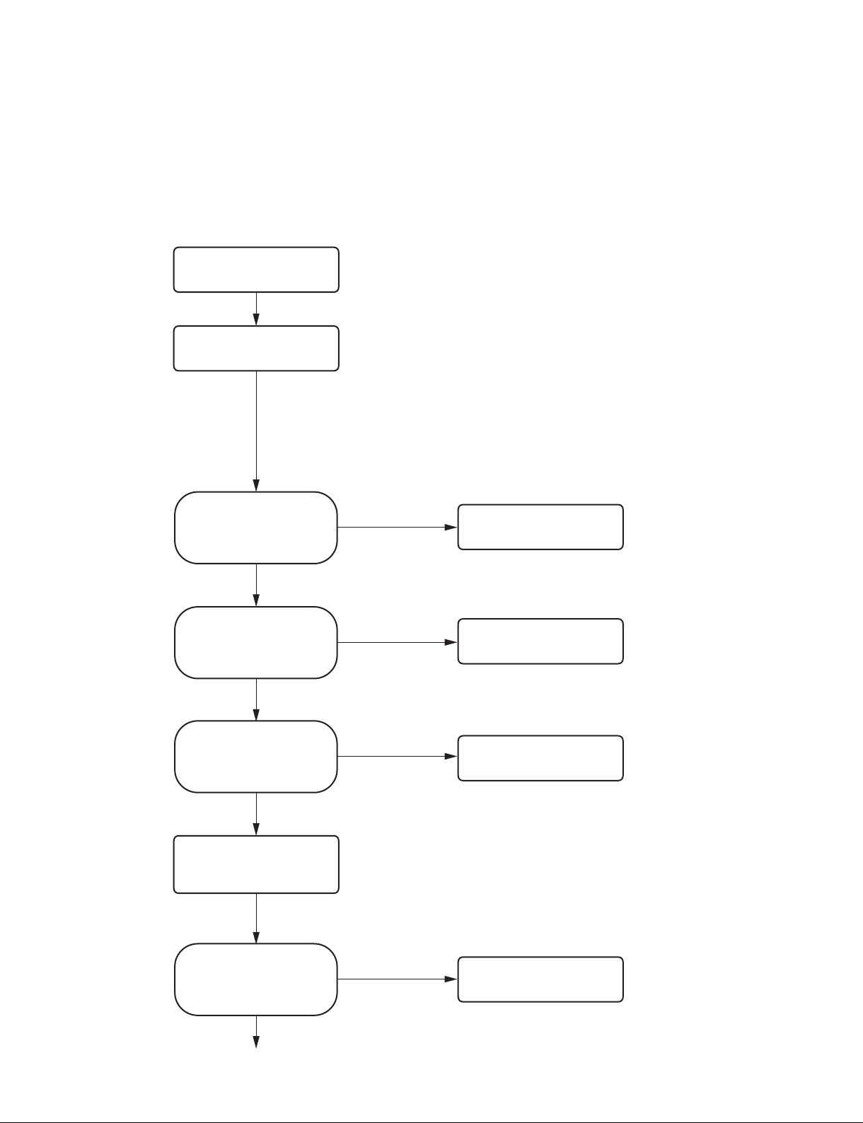
Before providing services, check symptoms according to the flow chart below.
Start
Serial number of this unit
Information of connection equipment (Modality name, application, etc.)
Check the information from a user.
Occurrence date and its status
Frequency of occurrence (Did defects occur for the first time, irregularly
several times, or in a specific case?)
Which operation did you perform after occurrence of defects?
$
The items above are used as an information source for analyzing defects.
Therefore, collect detailed information as far as possible.
Is the cause of defects streaks
(white or black) or scratches in
a print direction or a failure or
trouble?
Failure or trouble
Does this unit normally start with
the power turned on?
Yes
Is USB connection recognized?
Yes
Acquire the information of this unit
using utility software. (Refer to step
of “1. Information tab” in
3
Section 1-6-3.)
Stripes or flaws
No
No
$
Communication with this unit cannot be performed using utility software
when menu “DIGITAL” - “DRIVER” is set to “DRV: 897” .
In this case, start this unit in a service mode (refer to Section 1-8) and
use utility software.
Check the symptoms, clean the
thermal head or replace it.
&
Cleaning: Refer to Section 1-11-2.
Replacement: Refer to Section 3-7.
Refer to “2-2-1. Power does not
turn on even though the power
switch is turned on” .
Refer to “2-2-3. Printing cannot be
performed normally from PC or no
image is output” .
UP-D898MD/X898MD
Could the defects be determined
from user information and error
history? (Refer to steps 1 and
of “1. Information tab” in
2
Section 1-6-3.)
No
Go to next page
Yes
Check the determined point or
replace the relevant parts.
1-1 (E)
Page 10
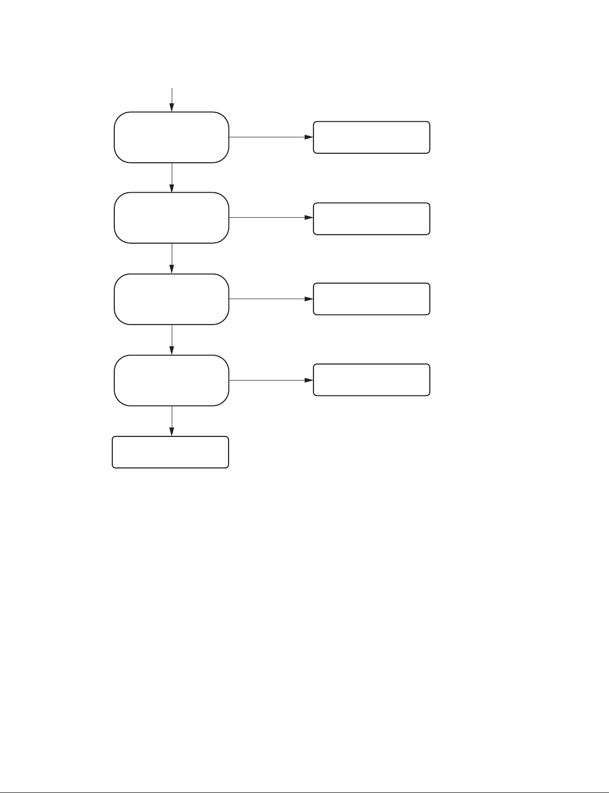
From the previous page
Can a defective point be
determined by self-diagnosis?
(Refer to Section 3-13.)
No
Can a 17-step test pattern be
normally printed?
(Refer to Section 3-1-3.)
No
Cannot paper be printed at all or
is paper printed in white?
No
Is the image in a test pattern
disturbed?
No
Yes
Yes
Yes
Yes
Check the determined point or
replace the relevant parts.
(Refer to Section 2-1.)
Normal
Refer to “2-2-3. Printing cannot be
performed normally from PC or no
image is output” .
Refer to “2-2-5. Print image is
distorted in the paper feed direction
(irregular feeding)” .
Check the contents of a trouble.
1-2 (E)
UP-D898MD/X898MD
Page 11
1-1-2. Flow Chart after Service
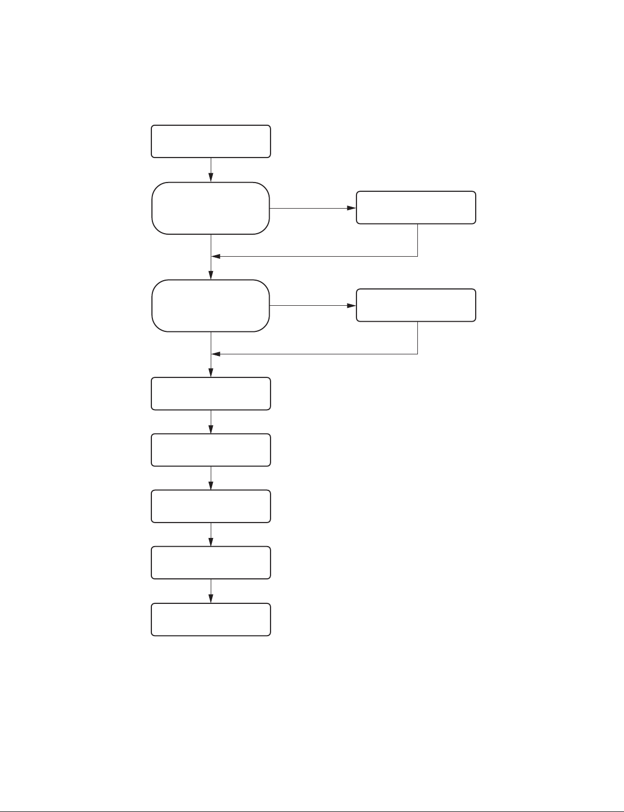
After terminating services, check symptoms according to the flow chart below.
Start
Was this unit disassembled?
No
Is upgrading of firmware required?
No
Install a UPP-110HG.
Print a 17-step test pattern.
(Refer to Section 3-1-3.)
Clean the thermal head and platen
roller. (Refer to Section 1-11.)
Yes
Yes
&
Thermal head: Refer to Section 1-11-2.
Platen roller: Refer to Section 1-11-3.
Perform self-diagnosis and check
that no problem exists in
assembling. (Refer to Section 3-13.)
Upgrade the firmware.
(Refer to Section 1-7.)
UP-D898MD/X898MD
Check the external view and
clean it. (Refer to Section 1-11-1.)
Return this unit to a user.
$
Check that paper and USB flash memory are removed.
1-3 (E)
Page 12
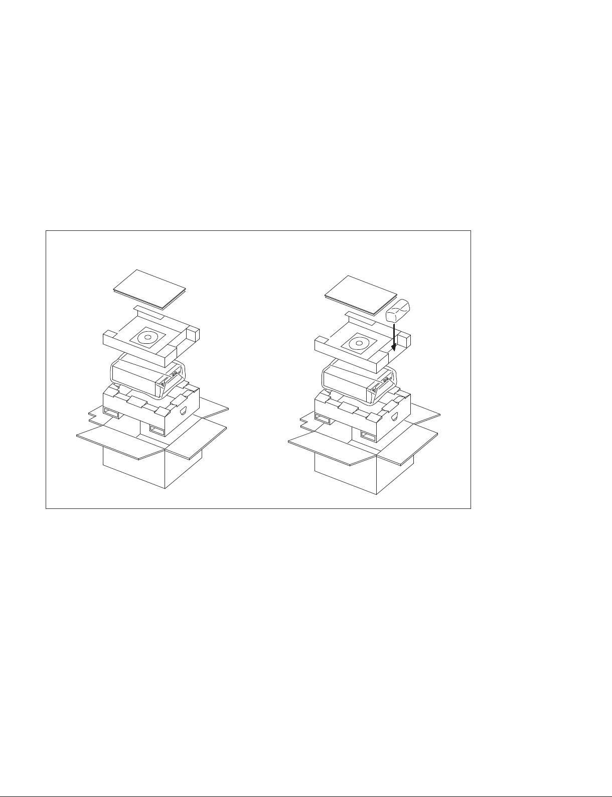
1-2. Precaution for Transporting
Perform the operation below so as to prevent the damage due to vibration and shock when transporting
this unit.
. Remove the printer paper and transport with closing the door.
. When you lift up the printer, do not hold the opened door. Otherwise, it may cause a failure due to an
excessive force applied to the door mechanism. Also, your hand might accidentally get caught between
the door and main unit resulting in injury.
. Use the packaging materials supplied for this unit.
n
Keep the packing materials removed during the delivery and installation. Do not discard them.
UP-D898MD UP-X898MD
1-4 (E)
UP-D898MD/X898MD
Page 13

1-3. Board Location and Main Parts Location
1-3-1. Board Location
KY-711 board
SE-1143 board
SU-167 board
MA-195 board
SE-1142 board
1-3-2. Main Parts Location
DC motor
Stepping motor
Thermal head
Switching regulator
UP-D898MD/X898MD
1-5 (E)
Page 14
1-3-3. Sensor Location
Head position sensor (Print)
Edge sensor
(Light receiving side)
Edge sensor
(Light emitting side)
Tray sensor
(Light receiving side)
Door sensor
Head position sensor
(Home)
Tray sensor
(Light emitting side)
1-4. Tightening torque
Tighten the following screws to the tightening torques as described below.
n
The screw (BVTT2.6 x 5) of this unit has two types of the tighten torque. Be careful not to confuse.
. B3 x 6: 0.80 ?0.05 N.m
. BVTT2.6 x 4: 0.80 ?0.05 N.m
. BVTT2.6 x 5 (for excluding paper holder): 0.80 ?0.05 N.m
. BVTT2.6 x 5 (for paper holder): 0.50 ?0.05 N.m
. P3 x 4: 0.50 ?0.05 N.m
. PS3 x 4: 0.80 ?0.05 N.m
. PS3 x 6: 0.80 ?0.05 N.m
. PS4 x 8: 1.40 ?0.15 N.m
. PSW3 x 8: 0.80 ?0.05 N.m
. LOCK ACE screw (M2): 0.20 ?0.05 N.m
. Tapping screw M1.7: 0.13 ?0.02 N.m
. N6, TYPE2: 1.20 ?0.10 N.m
When using the torque driver with the unit representation of cN.m, calculate the value as follows.
Example: 0.8 N.m = 80 cN.m
1-6 (E)
UP-D898MD/X898MD
Page 15
1-5. Removing/Installing the Cabinet
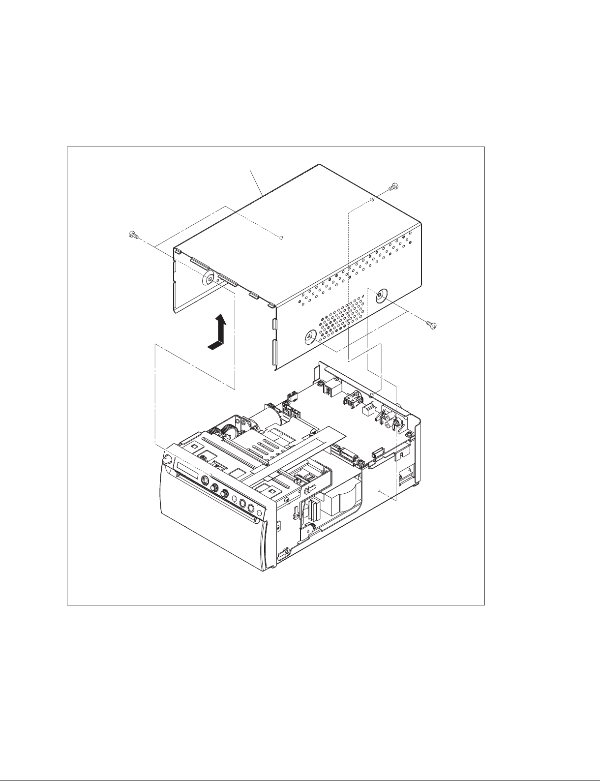
1-5-1. Top Cover
1. Remove the five screws, then remove the top cover in the direction of the arrow.
Top cover
B3 ) 6
) 6
B3
B3
) 6
The illustration indicates UP-X898MD.
2. To install, reverse the removal procedure.
UP-D898MD/X898MD
1-7 (E)
Page 16
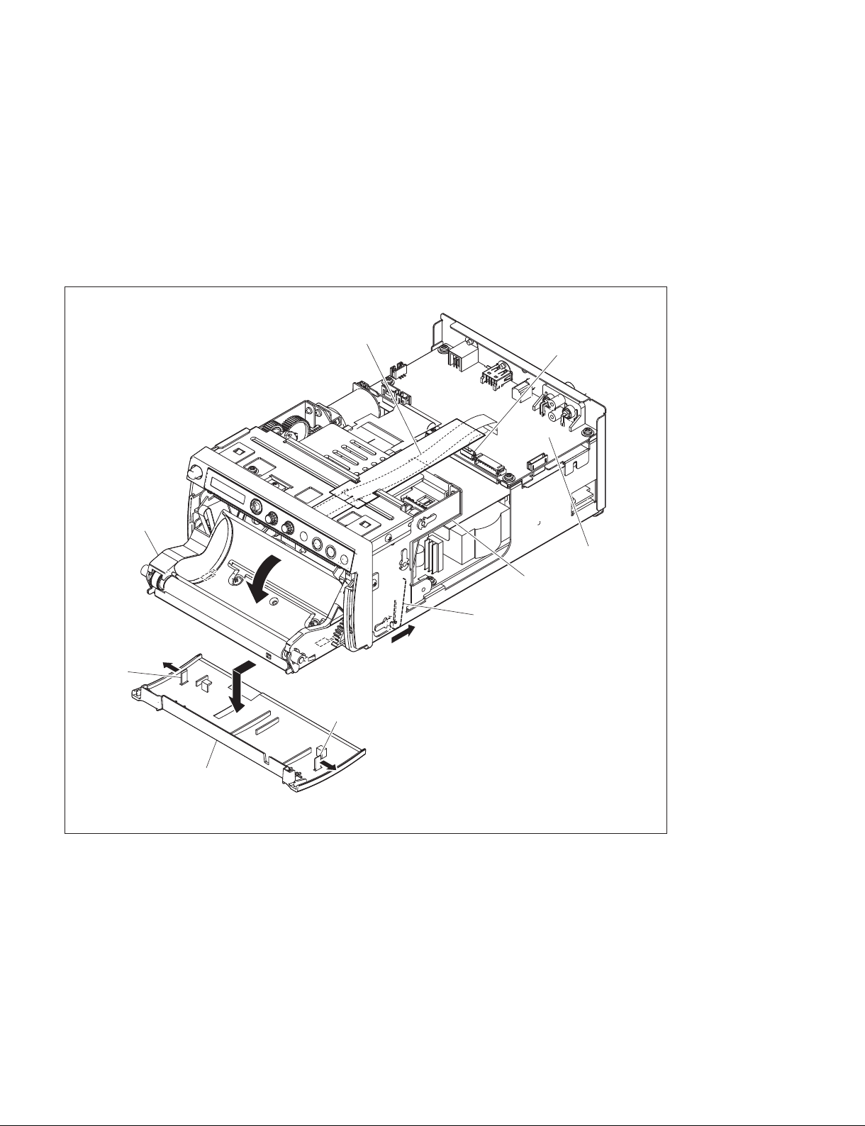
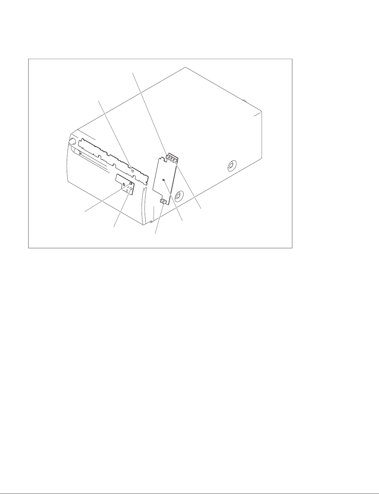
1-5-2. Front Panel Block Assembly
1. Remove the top cover. (Refer to Section 1-5-1.)
2. Release the lock arm on the mechanical deck portion (bottom) in the direction of the arrow A, then
open the door block assembly in the direction of the arrow B.
3. Remove the two hooks in the right and left directions of the arrows C, then remove the door panel in
the direction of the arrow D.
4. Disconnect the flexible flat cable from the connector (CN1103) on the MA-195 board.
Door block assembly
C
Hook
B
D
Flexible flat cable
CN1103
MA-195 board
Mechanical deck portion
Lock arm
A
Hook
1-8 (E)
Door panel
C
The illustration indicates UP-X898MD.
UP-D898MD/X898MD
Page 17
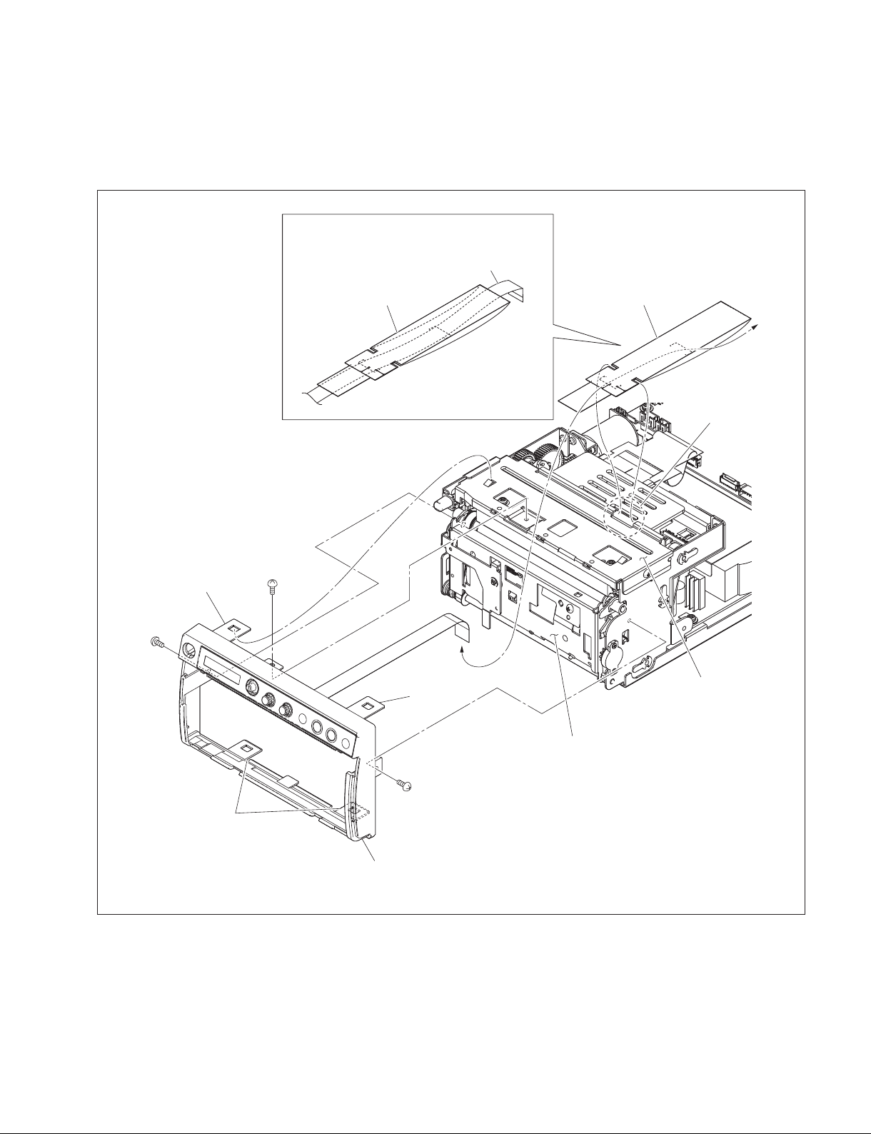
5. Close the door block assembly.
6. Remove the FFC guard (KY) from the portion A of the MD top chassis.
7. Remove the three screws and four hooks, then remove the front panel block assembly.
8. Remove the FFC guard (KY) from the flexible flat cable.
When attaching the flexible flat cable, route it
through the FFC guard (KY).
Flexible flat cable
BVTT
2.6 ) 4
Hook
BVTT
2.6
FFC guard (KY)
)
4
Hook
FFC guard (KY)
Portion A
MD top chassis
Hooks
9. To install, reverse the removal procedure.
UP-D898MD/X898MD
BVTT
2.6
)
4
Front panel block assembly
Door block assembly
The illustration indicates UP-X898MD.
1-9 (E)
Page 18
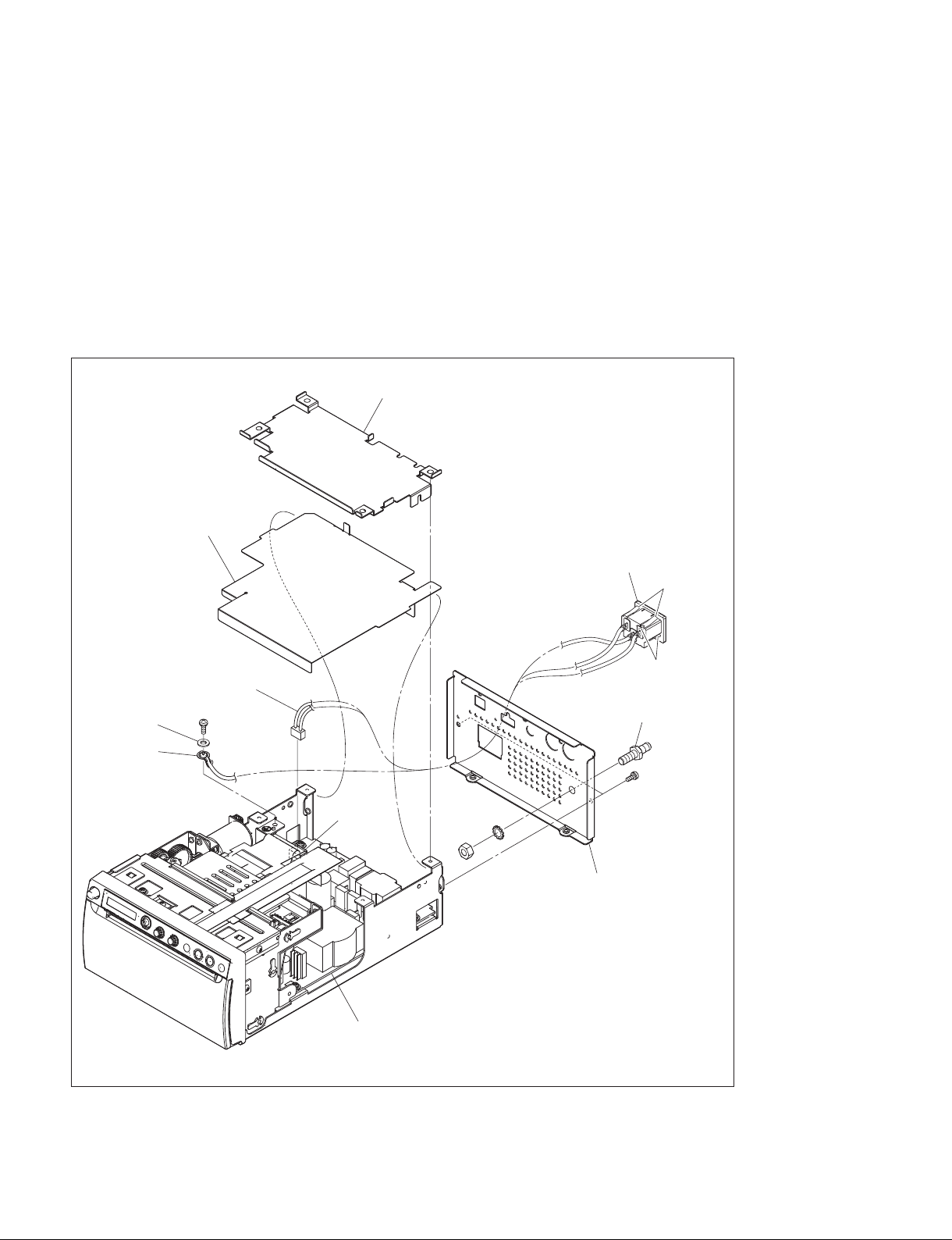
1-5-3. Rear Panel
1. Remove the top cover. (Refer to Section 1-5-1.)
2. Remove the MA-195 board. (Refer to Section 3-1.)
3. Remove the shield plate (MA) and insulating sheet (MA).
4. Remove the screw (PS4 x 8), then remove the washer (W4) and earth terminal.
5. Disconnect the harness from the connector (CN101) on the switching regulator.
6. Remove the two screws (P3 x 4), then remove the rear panel.
7. Remove the four hooks, then remove the AC inlet.
8. Remove the nut (N6) and washer (LW6), then remove the equipotential terminal.
Shield plate (MA)
Insulating sheet (MA)
AC inlet
Hooks
Harness
PS4 ) 8
W4
Earth terminal
CN101
Switching regulator
9. To install, reverse the removal procedure.
N6
Equipotential terminal
P3
LW6
Rear panel
The illustration indicates UP-X898MD.
Hooks
) 4
1-10 (E)
UP-D898MD/X898MD
Page 19

1-6. General Information of Utility Software
1-6-1. Required Equipment/Tools
. Personal computer (PC) having the USB interface
. OS: Windows Vista/7/8
. Utility software: Utility Tool for UP-DX898MD.exe
t
For obtaining the utility software, contact your local Sony Sales Office/Service Center.
. USB cable
n
Use the USB 2.0 certified USB cable having a length of 2 m or less. Use of cables other than specified
may cause unstable operation of this unit.
. Thermal Print Media: UPP-110HG (Part number: 1-772-473-13)
1-6-2. Preparation
1. Connect this unit and PC using the USB cable.
t
The installation of printer driver may be requested when this unit and PC are connected. However, it
is not required to install the printer driver when using this utility software.
2. Turn on the power of PC.
3. Press the power switch of this unit to turn on the power.
4. Start the utility software (Utility Tool for UP-DX898MD.exe).
UP-D898MD/X898MD
1-11 (E)
Page 20
1-6-3. Function Description
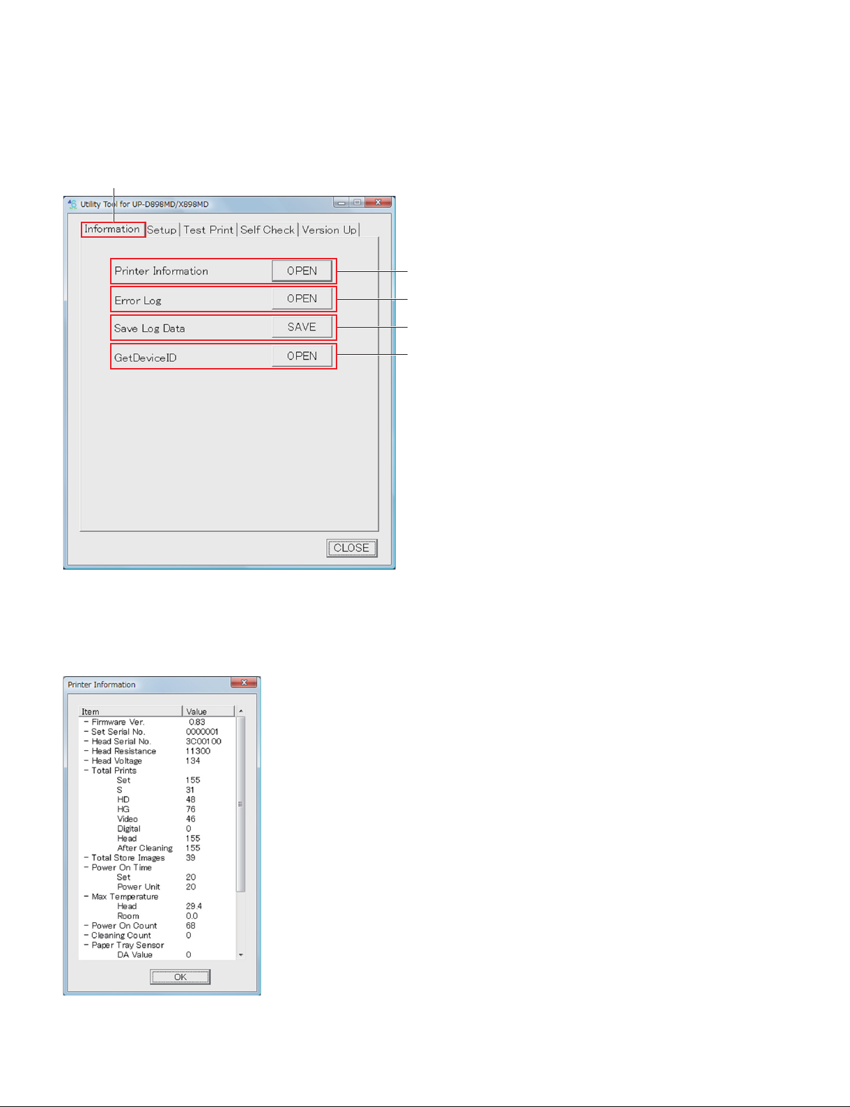
1. Information tab
Information tab
1
2
3
4
1 Printer Information
When you click the [OPEN] button, the information of this unit is obtained from EEPROM (IC507/
MA-195 board) of this unit and displayed.
1-12 (E)
UP-D898MD/X898MD
Page 21

. Firmware Ver.: Version of firmware
. Set Serial No.: Serial number of this unit
. Head Serial No.: Serial number of thermal head
. Head Resistance: Resistance value (Z) of thermal head
. Head Voltage: Voltage setting value (D/A value) of thermal head
. Total Prints:
Set: Total print count of this unit
S: Total print count of paper (UPP-110SE)
HD: Total print count of paper (UPP-110HD)
HG: Total print count of paper (UPT-110HG)
Video: Total print count of image captured from video signal
Digital: Total print count of digital image transmitted from PC
Head: Total print count of thermal head
After Cleaning: Total print count after cleaning of thermal head
. Total Store Images: Number of image stored in USB flash memory
. Power On Time
Set: Total power on time of this unit (h)
Power Unit: Total power of time of power unit (h)
. Max Temperature
Head: Maximum temperature of thermal head (dC)
Room: Maximum room temperature (dC)
. Power ON Count: Number of power ON times
. Cleaning Count: Number of thermal head cleaning times
. Paper Tray Sensor: Information of paper tray sensor (Luminance side: D201/SE-1143 board, light
receiving side: Q301/SE-1142 board)
DA Value: Amount of luminescence (D/A value)
High Level: Light receiving portion High level
Low Level: Light receiving portion Low level
Threshold: Light receiving portion threshold level
. Paper Front Sensor: Information of paper tray sensor (Luminance side: D301/SE-1142 board, light
receiving side: Q201/KY-711 board)
DA Value: Amount of luminescence (D/A value)
High Level: Light receiving portion High level
Low Level: Light receiving portion Low level
Threshold: Light receiving portion threshold level
. [OK] button: Closes the Printer Information screen.
UP-D898MD/X898MD
1-13 (E)
Page 22
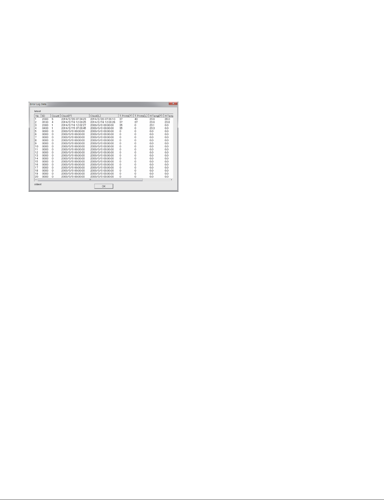
2 Error Log
When you click the [OPEN] button, the 20 errors that have occurred in the past are displayed. When the
number of error exceeds 20, the error is overwritten by the latest error beginning with the chronologically
oldest error (No. 20). However, when the same errors are overlapped (the errors of the same error code
occurred continuously), only the Count number of the latest error (No. 1) is overwritten (increased) and
the error No. 20 is not deleted.
t
For the error code ID, refer to Section 2-1.
. ID: Error code ID information
. Count: Number of overlapping errors
. Clock (F): Date and time when the first error is detected
. Clock (L): Date and time when the last error is detected (This is displayed only when the errors are
overlapped.)
. T.Prints (F): Total print count of this unit when the first error is detected
. T.Prints (L): Total print count of this unit when the last error is detected (This is displayed only when
the errors are overlapped.)
. H.Temp (F): Thermal head temperature (dC) when the first error is detected
. H.Temp (L): Thermal head temperature (dC) when the last error is detected (This is displayed only
when the errors are overlapped.)
. R.Temp (F): Room temperature (dC) when the first error is detected
. R.Temp (L): Room temperature (dC) when the last error is detected (This is displayed only when the
errors are overlapped.)
. [OK] button: Closes the Error Log screen.
3 Save Log Data
When you click the [Save] button, the menu setting and operation log information of this unit as well as
the information displayed in Printer Information and Error Log are saved as CSV format file on PC.
The saved file can be displayed by using the spreadsheet software such as Excel.
The information in this file is important when the person in charge of design performs a failure analysis.
4 GetDeviceID
Not used
1-14 (E)
UP-D898MD/X898MD
Page 23
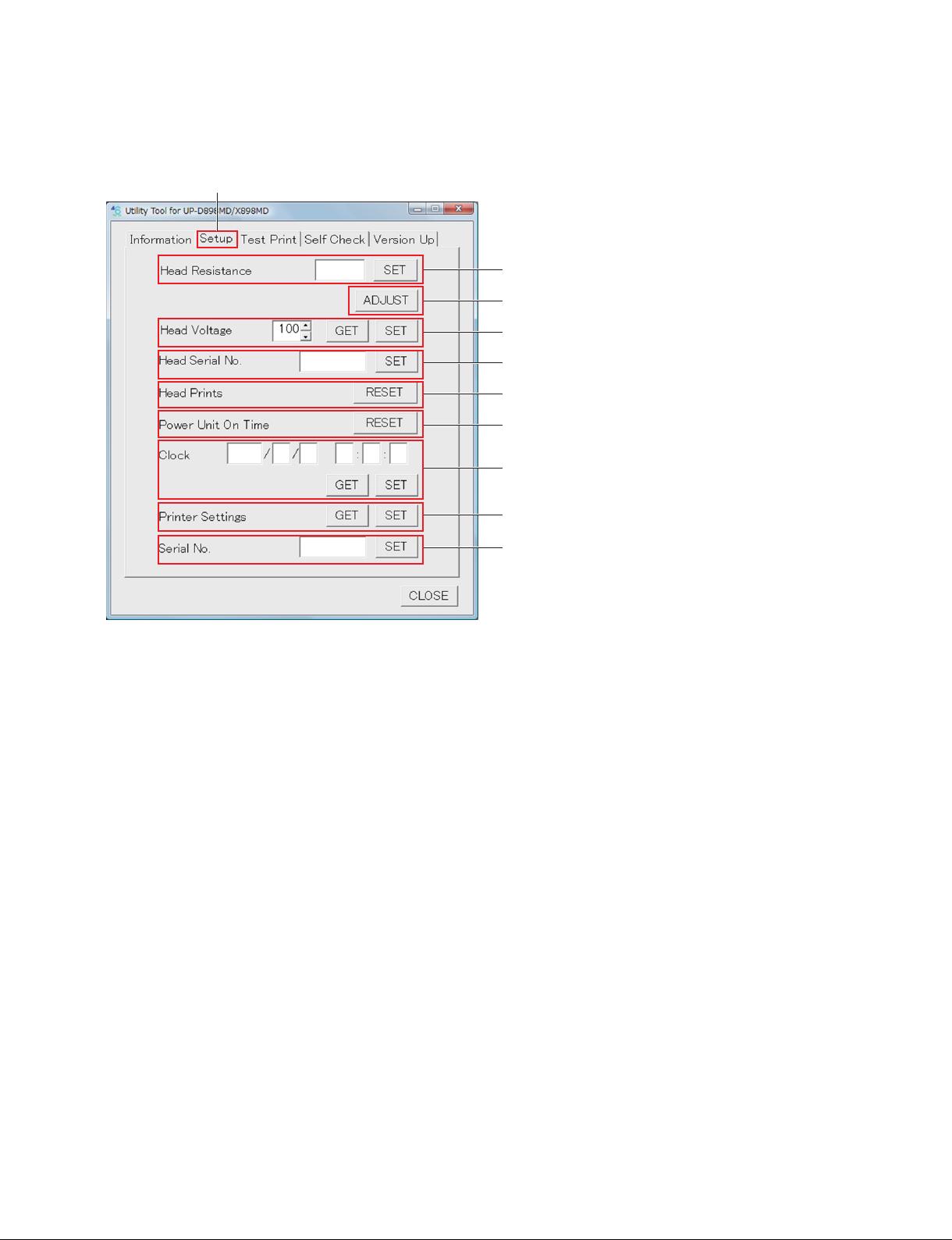
2. Setup tab
Setup tab
1
2
3
4
5
6
7
8
9
1 Head Resistance
Sets the thermal head resistance value.
When you click the [SET] button, the value in the edit box is written in EEPROM (IC507/MA-195
board) of this unit.
2 [ADJUST] button
Calculates the head voltage setting value based on the thermal head resistance value, and write the value
(D/A value) in EEPROM (IC507/MA-195 board) of this unit.
3 Head Voltage
Obtains and sets the thermal head voltage setting value (D/A value).
. [GET] button: When you click this button, the information stored in EEPROM (IC507/MA-195 board)
of this unit is displayed in the edit box.
. [SET] button: When you click this button, the value in the edit box is written in EEPROM (IC507/
MA-195 board) of this unit.
4 Head Serial No.
Sets the thermal head serial number.
When you click the [SET] button, the number in the edit box is written in EEPROM (IC507/MA-195
board) of this unit.
5 Head Prints
When you click the [RESET] button, the total print count of thermal head is reset.
UP-D898MD/X898MD
1-15 (E)
Page 24

6 Power Unit On Time
When you click the [RESET] button, the total on time of power unit is reset.
7 Clock
Obtains and sets the date/time information.
. [GET] button: When you click this button, the date/time information obtained from this unit is dis-
played in the edit box.
. [SET] button: When you click this button, the date/time information in the edit box is set in this unit.
8 Printer Settings
Obtains and sets the menu setting information of this unit.
. [GET] button: When you click this button, the menu setting information stored in EEPROM (IC507/
MA-195 board) of this unit is saved as binary file (.CNS) on PC.
. [SET] button: When you click this button, the menu setting information of the specified binary file
(.CNS) is written in EEPROM (IC507/MA-195 board) of this unit.
9 Serial No.
Sets the serial number of this unit.
When you click the [SET] button, the number in the edit box is written in EEPROM (IC507/MA-195
board) of this unit.
1-16 (E)
UP-D898MD/X898MD
Page 25
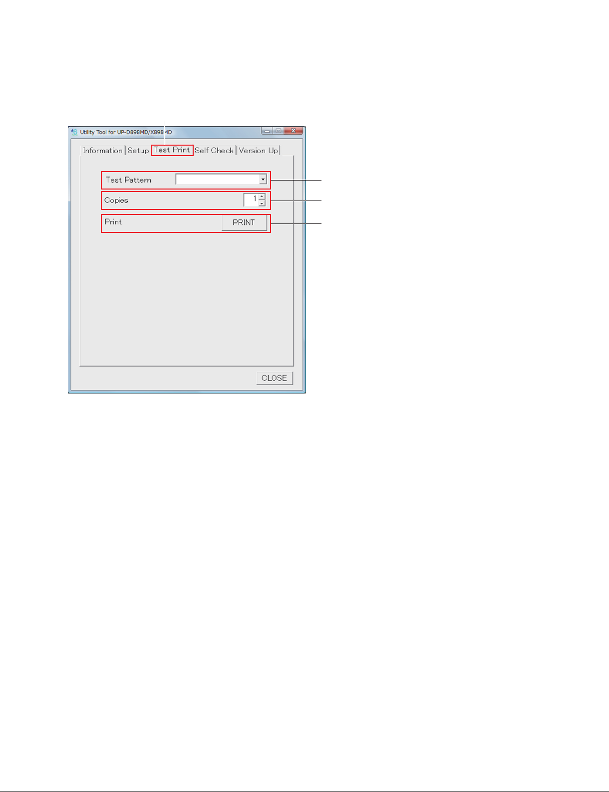
3. Test Print tab
Test Print tab
1
2
3
1 Test Pattern
Selects the image pattern to be printed.
. STEP: Built-in stair-step pattern
. CROSS STEP: Built-in cross step pattern
. LAMP: Built-in lamp image
. CROSS LAMP: Built-in cross lamp image
. SKEW LAMP: Built-in skew lamp image
. HEAD CONFIRM PAT1: Built-in thermal head confirmation pattern 1
. HEAD CONFIRM PAT2: Built-in thermal head confirmation pattern 2
. LOG: Log information in this unit
. BLACK (S/L)
. DARK GRAY (S/L)
. GRAY (S/L)
. LIGHT GRAY (S/L)
. WHITE (S/L)
*
: Built-in 100% black pattern
*
*
: Built-in gray pattern
: Built-in gray pattern (darker)
*
*
: Built-in gray pattern (lighter)
: Built-in 100% white pattern
*: Print size: Horizontal x Vertical [mm]
S: 100 x 75
L: 100 x 117
UP-D898MD/X898MD
1-17 (E)
Page 26
2 Copies
Sets the number of copies.
You can set the number of copies from 1 to 255 sheets.
3 Print
When you click the [PRINT] button, the test print is performed.
The pattern selected in 1 is printed by the number of copies set in 2.
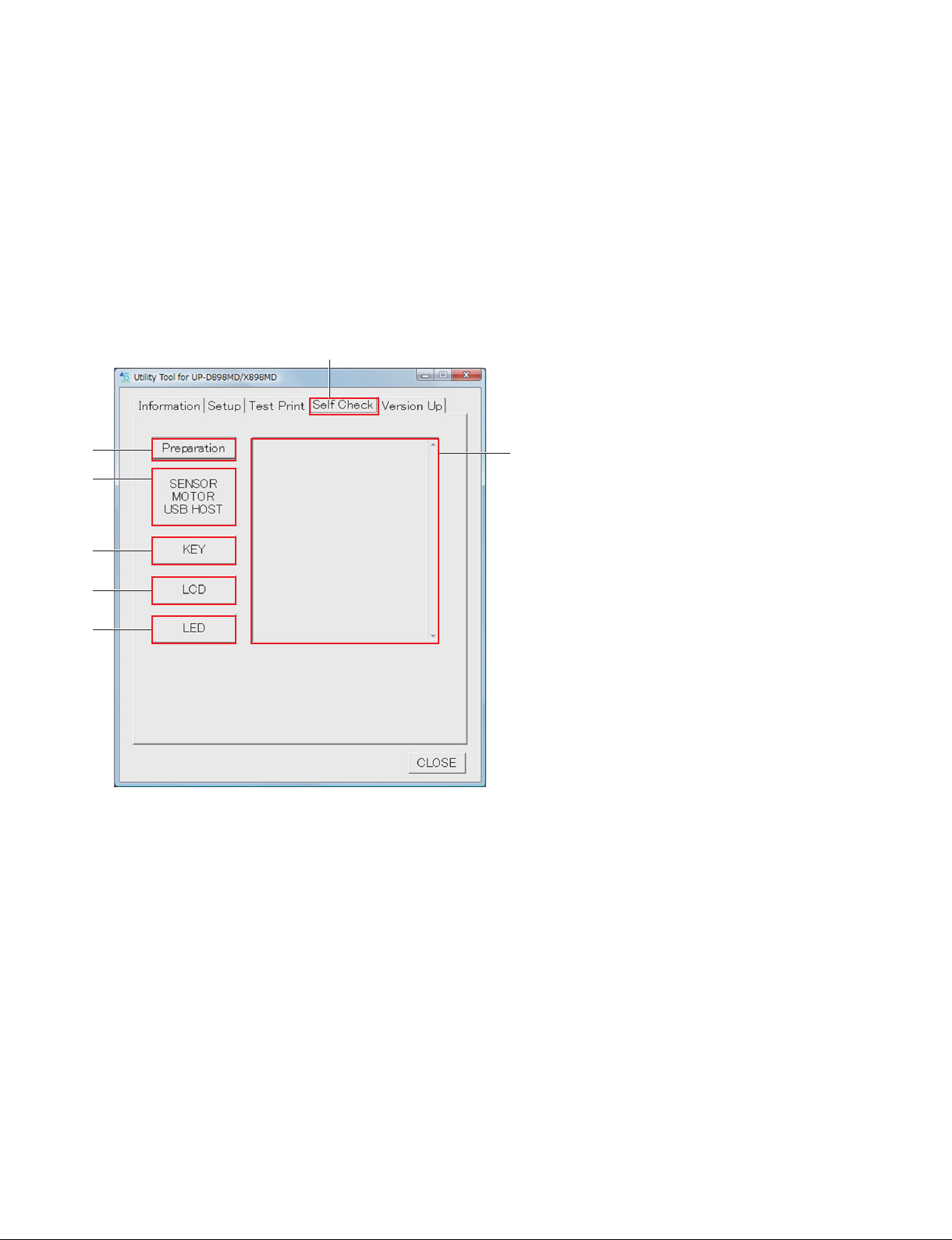
4. Self Check tab
Self Check tab
1
2
3
4
5
6
1 [Preparation] button
Performs the preparation of self check.
When this button is clicked, “Before checking… Eject the paper. Close the door. Insert USB Flash Drive.
(UP-X898MD)” is displayed in the edit box 7.
According to the display, eject the paper, close the door and connect the USB flash memory (UP-X898MD
only).
2 [SENSOR|MOTOR|USB|HOST] button
Performs the self check of SDRAM, EEPROM, sensors, and DC motor and thermistor of thermal head in
this unit.
After the check is completed, if there is no defective portion, “Check Result No Error, Check OK!” is
displayed in the edit box 7.
If any defective portion is detected, it is displayed.
t
For the cause and remedy of the defective portion, refer to Section 2-1.
1-18 (E)
UP-D898MD/X898MD
Page 27

3 [KEY] button
When this button is clicked, the Check Key screen is opened. The conduction check of button, knob and
menu lever of this unit is performed.
Operate the front operation device displayed on LCD of this unit, then click the [OK] button of the Check
Key screen.
After the check is completed, the check result is displayed in the edit box 6.
4 [LCD] button
When this button is clicked, the Check LCD screen is opened, and all LCDs of this unit light up. Visually
check that all LCDs of this unit are lit.
After the check is completed, click the [OK] button of the Check LCD screen.
5 [LED] button
When this button is clicked, the Check LED screen is opened, and all LEDs of this unit light up.
. Button LED: Blinks in white.
. LCD backlight LED: Blinks in green and amber alternately.
. USB access LED (UP-X898MD only): Blinks in green and amber alternately.
Visually check that all LEDs of this unit blink.
After the check is completed, click the [OK] button of the Check LED screen.
6 Edit box
Displays the check result and message.
UP-D898MD/X898MD
1-19 (E)
Page 28
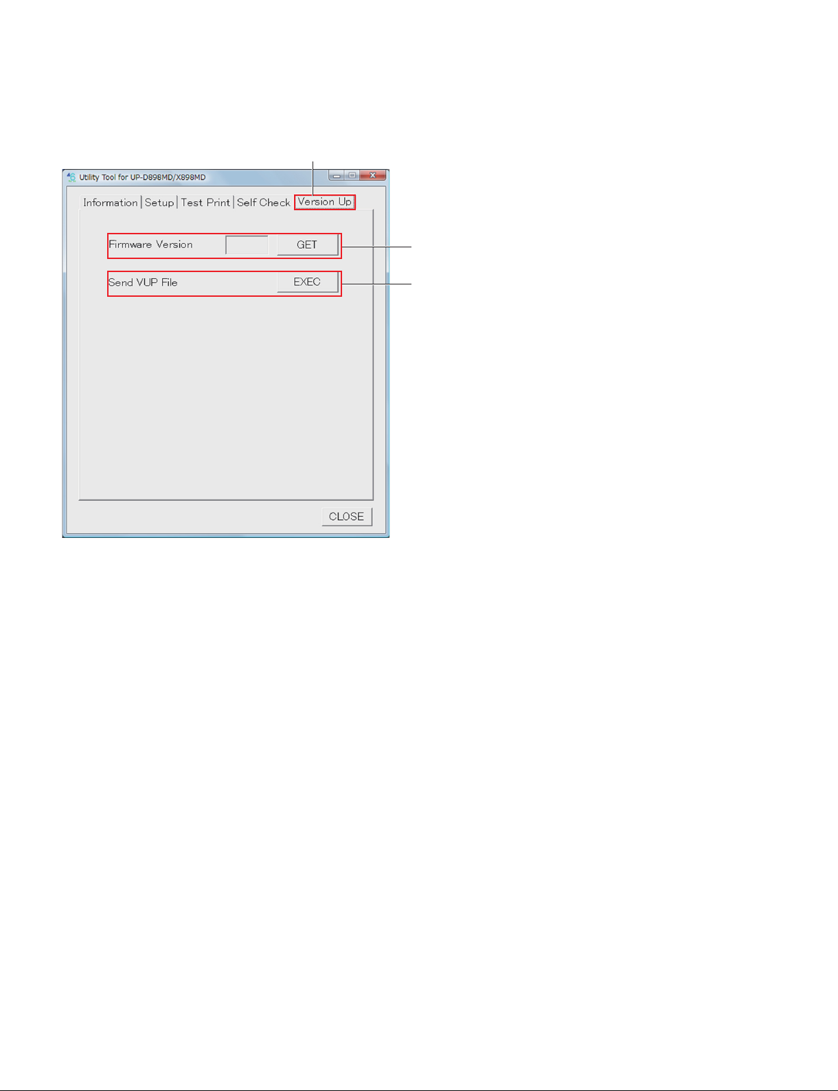
5. Version Up tab
Version Up tab
1
2
1 Firmware Version
Displays the firmware version of this unit.
When the [GET] button is clicked, the firmware version is displayed in the edit box.
2 Send VUP File
Performs the firmware version upgrade.
When the [EXEC] button is clicked, the specified version upgrade file is sent to this unit.
n
If the power is turned off in the course of the firmware writing, this unit will not start. Never turn off the
power of this unit before completing the writing. If the power is accidentally turned off and this unit will
not start, replace the MA-195 board. (Refer to Section 3-1.)
t
For the firmware version upgrade procedure, refer to Section 1-7.
1-20 (E)
UP-D898MD/X898MD
Page 29
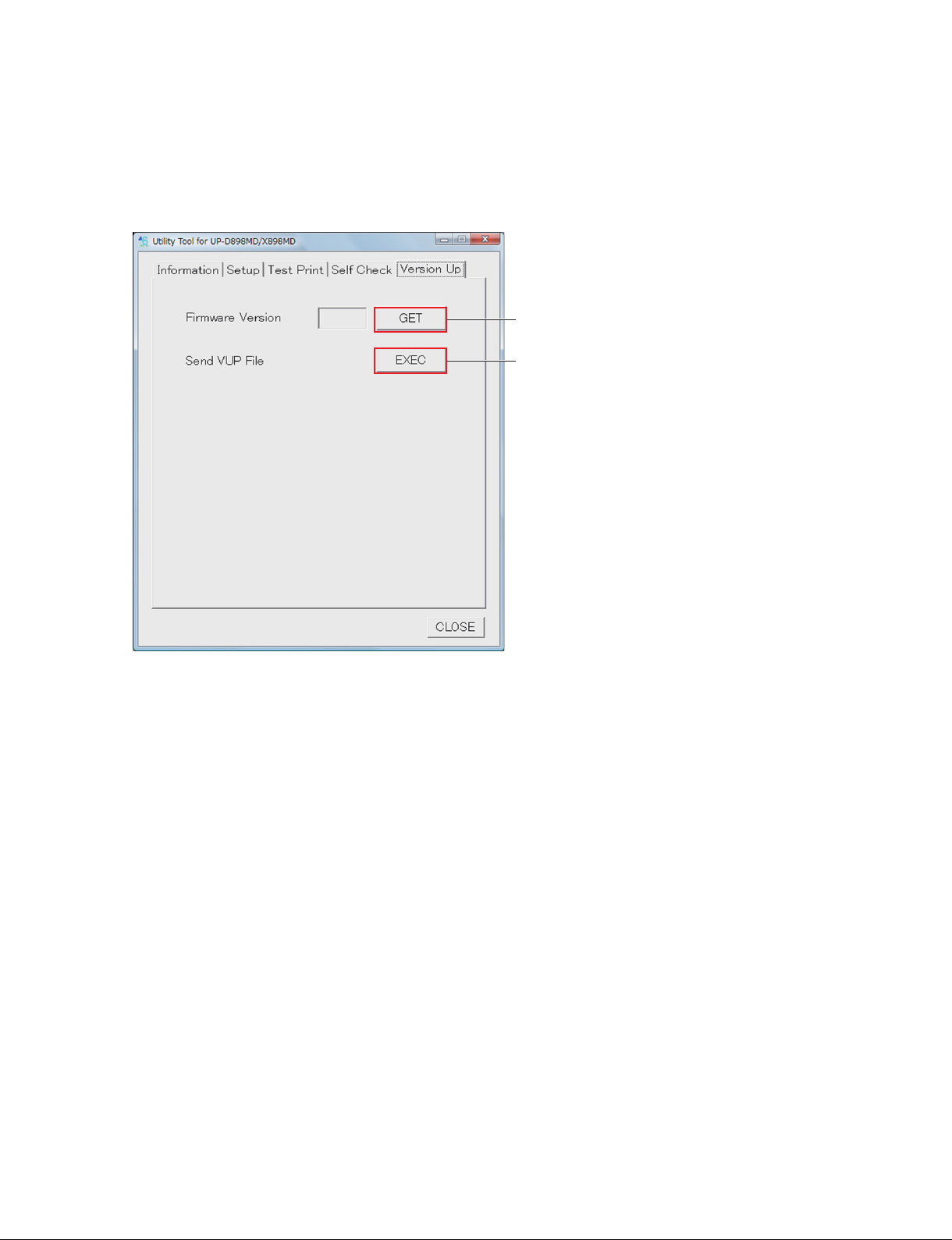
1-7. Firmware Version Upgrade
1. Start the utility software. (Refer to Section 1-6.)
2. Click the [GET] button of “Firmware Version” of the Version Up tab.
The version of the firmware currently installed in this unit is displayed.
[GET] button
[EXEC] button
3. Write down the current firmware version.
4. Click the [EXEC] button of “Send VUP File”.
5. Select the firmware (vup) file, and then click the [OPEN] button.
After the file is transferred, the firmware writing is started.
The display of LCD during the firmware writing is as follows.
. UPGRADE (blinks): Information is being written in FLASH.
. REBOOT (lights up): Writing is completed.
When the firmware writing is completed, 3 beep sounds are made.
n
If the power is turned off in the course of the firmware writing, this unit will not start. Never turn off
the power of this unit before completing the writing. If this unit will not start, replace the MA-195
board. (Refer to Section 3-1.)
6. Check that the writing is completed, and then restart this unit.
7. Click the [GET] button of “Firmware Version” of Version Up tab.
8. Check that the firmware is upgraded to the latest version.
UP-D898MD/X898MD
1-21 (E)
Page 30

1-8. Service Mode
It is possible to perform the printing of built-in pattern and the various settings with this unit alone. This
mode is used when you cannot use the utility software due to the USB device failure and so forth.
1-8-1. Startup Procedure
1. Turn on the power while pressing and holding the [FEED] button and [COPY] button simultaneously.
2. After approx. 4 seconds, check that the LCD backlight of this unit blinks in green and amber alternately, and then release each button.
The service mode is started.
1-8-2. Service Mode Menu
When this unit is started in the service mode, the first item of menu is changed from “HISTORY” (normal
mode) to “SERVICE”.
The menu structure of service mode is as follows.
When this unit is started in the service mode, even if you do not operate the button for approx. 20 seconds,
the unit does not exit from the menu mode because the time out function does not work.
READY
SERVICE
PATERN Test pattern print
SV.QTY Number of test pattern print
STR.MEM USB flash memory saving function ON/OFF
HEAD.V Thermal head voltage setting
LPF Low pass filter
PRT.LOG Log print
INIT Initialization of setting
MECHA Mechanical operation of individual motors
TEMP Temperature display
TMODE Switching of Toshiba mode
RMCAP Remote capture timing
PRT.HELP
ADJUST
VIDEO
DIGITAL
PRT.MENU
PREF.
CLEAN.TH
CONFIG.
SERIAL.N
1-22 (E)
UP-D898MD/X898MD
Page 31

1. Test Pattern Print
When you select the test pattern and press the menu lever, the printing is started.
The predetermined number of test pattern is printed by setting the number of print in “SV.QTY” in advance. When you want to discontinue the printing, press the [FEED] button, [OPEN] button, or [CUT]
button on the front portion of this unit.
Menu item Image pattern
C.STP Built-in cross step pattern
N.STP Built-in stair-step pattern
C.LMP Built-in cross lamp image
N.LMP Built-in lamp image
S.LMP Built-in skew lamp image
HD2 Built-in thermal head confirmation pattern 2
HD1 Built-in thermal head confirmation pattern 1
D.ADJ Density adjustment print (not used in service)
00. (L/S)
3F. (L/S)
7F. (L/S)
BF. (L/S)
FF. (L/S)
* Print size: Horizontal x Vertical [mm]
S: 100 x 75
L: 100 x 117
*
Built-in 100% black pattern
*
Built-in gray pattern (darker)
*
Built-in gray pattern
*
Built-in gray pattern (lighter)
*
Built-in 100% white pattern
2. Number of Test Pattern Print
Sets the number of test pattern (PATTERN) print.
SV.QTY:C When setting to continuous print
SV.QTY:10 When setting to 10 sheets.
:
SV.QTY:1 When setting to 1 sheet.
When setting to continuous print, the test pattern is printed continuously.
When you want to discontinue the printing, press the [FEED] button or [OPEN] button on the front
portion of this unit.
3. USB Flash Memory Saving Function ON/OFF
Sets ON/OFF of the function of saving the image data in the USB flash memory.
To enable the change of setting, restart this unit.
The factory setting is “S.MEM:ON”.
. S.MEM:ON: Data can be saved in the USB flash memory.
. S.MEM:OFF: Data cannot be saved in the USB flash memory. This unit does not recognize the USB
flash memory even if it is connected.
UP-D898MD/X898MD
1-23 (E)
Page 32

4. Thermal Head Voltage Setting
Sets the thermal head voltage setting value (D/A value).
To set the voltage setting value, change the value by operating the menu lever up and down when the
“H.V: (value)” is displayed, and then press the menu lever.
5. Low Pass Filter
Sets ON/OFF of the low pass filter circuit in IC302 on the MA-195 board.
The factory setting is “LPF:OFF”.
. LPF:ON: When setting the low pass filter to ON
. LPF:OFF: When setting the low pass filter to OFF
6. Log Print
Prints the log information (print count, error, etc.) in this unit.
Set paper in the tray.
7. Initialization of Setting
Initializes the setting and log information.
. INT:MENU: Initializes the content to be set by menu.
. INT:PWR: Resets the total power on time of switching regulator.
. INT:H:PRN: Clears the total print count of thermal head to 0.
Category Menu Normal Service tool (Printer
Settings)
Normal BRIGHT
CONTRAST
GAMMA
SHARPNESS
TONE
ASPECT
COLOR
FIELD
INTERRUPT
MULTI
SCALE
SCAN
SIDE
S.H(NTSC)
S.V(NTSC)
E.H(NTSC)
E.V(NTSC)
S.H(PAL)
S.V(PAL)
E.H(PAL)
E.V(PAL)
DRIVER
RESIZE
BACKWORD
INFO
INVERT
MIRROR
QTY
SAVE LOAD RE-
SET
OOOO OO
OOOO OO
OOOO OO
OOOO OO
OOOO OO
OOOO OO
OOOO OO
OOOO OO
OOOO OO
OOOO OO
OOOO OO
OOOO OO
OOOO OO
OOOO OO
OOOO OO
OOOO OO
OOOO OO
OOOO OO
OOOO OO
OOOO OO
OOOO OO
OOOO OO
OOOO OO
OOOO OO
OOOO OO
OOOO OO
OOOO OO
OOOO OO
INT
MENU
PWR H.PRN
GET SET
1-24 (E)
UP-D898MD/X898MD
Page 33

Category Menu Normal Service tool (Printer
Settings)
SAVE LOAD RE-
SET
Normal AUTO.LOCK
BEEP
BLANK
FEED
PP.TYPE
SPEED
Service SV.QTY Initialization and changes are not performed.
STR.MEM
HEAD V
LPF
TMODE
RM.CAP
Printer Information
Error Log All contents Initialization and changes are not performed.
Operation log All contents Initialization and changes are not performed.
Total Prints(HEAD)
Power On Time(Power
Unit)
Others Initialization and changes are not performed.
OOOO OO
OOOO OO
OOOO OO
OOOO OO
OOOO OO
OOOO OO
INT
MENU
PWR H.PRN
OOO
OOO
GET SET
OO
OO
OO
OO
OO
OO
OO
8. Mechanical Operation of Individual Motors
Performs the operation of individual motors of this unit.
n
Be sure to use this function after sufficiently understanding the mechanical structure of this unit. Otherwise, it may cause a breakage.
FEED:FW.H: Performs stepping motor operation. (Paper feed direction, during high speed printing PPS)
FEED:BC.H: Performs stepping motor operation. (Paper return direction, during high speed printing PPS)
FEED:FW.L: Performs stepping motor operation. (Paper feed direction, during low speed printing PPS)
FEED:BC.L: Performs stepping motor operation. (Paper return direction, during low speed printing PPS)
HEAD:OP.F: Performs thermal head operation in the forward direction. (Moves thermal head to OPEN.)
HEAD:HM.F: Performs thermal head operation in the forward direction. (Moves thermal head to HOME.)
HEAD:PR.F: Performs thermal head operation in the forward direction. (Moves thermal head to PRINT.)
HEAD:OP.B: Performs thermal head operation in the backward direction. (Moves thermal head to OPEN.)
HEAD:HM.B: Performs thermal head operation in the backward direction. (Moves thermal head to HOME.)
HEAD:PR.B: Performs thermal head operation in the backward direction. (Moves thermal head to PRINT.)
9. Temperature Display
Displays the current temperature data.
Example)
. H:28.5: Thermal head temperature 28.5 dC
10. Toshiba Mode
Switches whether or not to display the field angles “SC:T1” and “SC:T2” that are exclusive for Toshiba in
the “SCAN” menu. When switched, the content of menu setting is reset.
. TMODE: TM:ON: Enables to select the field angles exclusive for Toshiba
. TM:OFF: Disables to select the field angles exclusive for Toshiba
11. Remote Capture Timing
Adjusts the time from the point the remote key such as remote commander (RM-091) is pressed till the
point the video image is captured.
The video image is captured after waiting for setting value x Vsync minutes.
The factory setting is 0.
UP-D898MD/X898MD
1-25 (E)
Page 34

1-9. Menu Lock Function
The menu lock function locks and unlocks the operation on a menu lever, CONTRAST control knob, and
BRIGHT control knob. Unlock it when operation is locked during maintenance service. Lock the operation after maintenance service is completed.
An alarm (“beep”) sounds when you operate the menu lever, CONTRAST control knob, and BRIGHT
control knob during lock. “LOCK” then appears on the LCD display of this unit.
1. Turn on the power switch while pressing the menu lever.
2. Check that the buzzer “beeps” after about three seconds and release your hand from the menu lever.
“LOCK” appears on the LCD display of this unit when operation is locked. “UNLOCK” appears
when operation is unlocked.
Menu lever
LCD
Power switch
CONTRAST control knob
BRIGHT control knob
1-26 (E)
UP-D898MD/X898MD
Page 35

1-10. Lithium Battery (UP-X898MD)
The UP-X898MD mounts a lithium battery for operating a watch. The lithium battery is parts that have
the length of life. It is recommended to replace it when five years pass after a lithium battery is manufactured.
. Be sure to use IEC-60086-4 certified products as a lithium battery.
. Use a lithium battery (CR2032 type): 1-528-174-72 during replacement.
Replacement
1. Remove the top cover. (Refer to Section 1-5-1.)
2. Remove the lithium battery from the battery holder on an MA-195 board.
Remove the lithium battery in the direction
of the arrow.
Lithium battery
Lithium battery
Battery holder
3. To install, reverse the removal procedure
MA-195 board
UP-D898MD/X898MD
1-27 (E)
Page 36

1-11. Cleaning
1-11-1. Cleaning the Cabinet
n
When solvents such as benzene or thinner, or acid, alkaline or abrasive detergent, or chemical cleaning
cloths are used on the dirty cabinet, the surface finish may be damaged. Take care with respect to the
following:
. Clean the cabinet with a 50 to 70 v/v% concentration of isopropyl alcohol or a 76.9 to 81.4 v/v% con-
centration of ethanol.
. Stubborn stains may be removed with a soft cloth such as a cleaning cloth lightly dampened with mild
detergent solution and then clean using the above chemical solution.
. Do not use unnecessary force to rub the cabinet with a stained cloth. The cabinet may be scratched.
. Do not keep the cabinet in contact with a rubber or vinyl resin product for a long period of time.
The surface finish may deteriorate or the coating may come off.
1-11-2. Cleaning the thermal head
If the thermal head is contaminated, the streaks, white spots or scratches may appear on the print image.
Wipe the stains of the thermal head with a clean and soft cloth dampened with ethanol in concentrations
of 76.9 to 81.4 v/v%.
n
Do not use the gauze because it generates debris.
1-28 (E)
UP-D898MD/X898MD
Page 37

1-11-3. Cleaning the Platen Roller
If the paper cannot be fed smoothly when printing or if the paper can be easily pulled out by hand, the
platen roller may be dirty. In such a case, clean the platen roller with a soft cloth soaked in a 76.9 to 81.4
v/v% concentration of ethanol.
1. Turn on the power switch.
2. Press the [OPEN] button to open the door panel assembly.
3. Wipe the platen roller gently with a soft cloth soaked in ethanol.
n
. After the wiped surface is completely dried, press the [FEED] button to rotate the platen roller and
wipe other portion.
. Do not rotate the platen roller with the hand.
. Do not use the gauze because it generates debris.
Platen roller
4. Press the [FEED] button.
The platen roller rotates by about 120 degrees.
n
After the platen roller stops, start cleaning the platen roller.
[FEED] button
$
Be careful not to interpose your fingers when the platen roller is in rotation.
5. Repeat steps 3 and 4 and clean the whole surface of the platen roller.
6. After the platen roller has been dried, close the door block assembly manually.
UP-D898MD/X898MD
1-29 (E)
Page 38

1-12. Periodic Inspection and Periodic Replacement Parts
Parts that must be periodically inspected and replaced are as shown in the table below.
Parts name Description Refer to
Lithium battery
(UP-X898M only)
. Be sure to use IEC-60086-4 certificated products as a lithium battery.
Use a lithium battery (CR2032 type):1-528-174-72 when replacing the lithium battery. (Only UP-X898MD)
Replace the lithium battery every five years (rough standard) or when the
date is significantly shifted even after it is set.
Section 1-10
1-13. Print Size
1-13-1. Rough Standard of Print Size
1. When a video input signal is printed (Only UP-X898MD)
Paperfeed direction
Height
Width
NTSC PAL
SCAN SIDE ASPECT Width Height Width Height
NORMAL OFF 1:1 90.0 93.8 90.0 93.0
4:3 90.0 70.5 90.0 68.5
ON 1:1 92.7 90.2 92.3 91.3
4:3 92.7 118.0 92.3 121.5
WIDE1 OFF 1:1 94.4 96.8 94.4 96.5
4:3 94.4 72.7 94.4 71.0
ON 1:1 96.0 94.4 95.7 95.8
4:3 96.2 124.3 95.7 127.3
WIDE2 OFF 1:1 95.5 99.7 95.5 98.2
4:3 95.5 75.0 95.5 72.8
ON 1:1 99.0 96.7 98.0 96.0
4:3 99.0 125.6 98.0 128.7
. The tolerance of length is width ?0.5 mm and height ?1.0 mm.
. When MULTI is valid, the size per screen is a value of 1/2, respectively.
2. When a digital (USB) input signal is printed
Paper size Width Height
960 x 1280 99.8 74.9
1280 x 1280 99.8 99.8
1920 x 1280 99.8 149.8
3840 x 1280 99.8 299.5
4096 x 1280 99.8 319.5
. The tolerance of length is width ?0.5 mm and height ?1.0 mm.
1-30 (E)
UP-D898MD/X898MD
Page 39

1-13-2. Interval Between Print Screens
The interval of print screens is as shown in the table below by the setting of “--FEED” and “--BLANK” in
a COFIG menu.
--FEED --BLANK Interval (mm)
OFF _ 3.5 ?1.0
ON S 10.5 ?1.0
ON L 25.5 ?1.0
1-13-3. Blank in Horizontal Direction
The blank in a horizontal direction is not prescribed.
However, confirm that the printed image is not cut.
1-14. Lead-free Solder
All boards mounted in this unit use lead-free solder. Be sure to use lead-free solder when repairing the
boards of this unit. A lead free mark (LF) indicating that the solder contains no lead is printed on each
board.
(Caution: Some printed circuit boards may not come printed with the lead free mark due to their particular
size.)
: LEAD FREE MARK
n
. The lead-free solder melts at a temperature about 40 dC higher than the ordinary solder, therefore, it is
recommended to use the soldering iron having a temperature regulator.
. The ordinary soldering iron can be used but the iron tip has to be applied to the solder joint for a slightly
longer time. The printed pattern (copper foil) may peel away if the heated tip is applied for too long, so
be careful.
UP-D898MD/X898MD
1-31 (E)
Page 40

Page 41

Section 2
Troubleshooting
2-1. Error Log Acquisition Procedure
A maximum of up to 20 errors that occurred during the printing operation are stored in this unit.
The error information can be obtained by using the log print (refer to Section 1-8-2) and utility software
(refer to Section 1-6).
It is possible to predict the possible defective portion of this unit based on the error information. Use it for
trouble analysi
2-1-1. Error Code Table
ID Symptom Possible cause Remedy
2001h
2102h
0100h
4102h
0102h
1100h
3100h
4100h
8100h
0101h
3102h
4103h
0103h
3101h
4101h
1102h
8102h
2103h
Door open has failed. Door drive system failure Check the door drive system.
Thermal head cannot be
moved from the home
position to the printing
position.
Thermal head cannot be
moved from unspecified
position to the home
position.
Thermal head cannot be
moved from the printing
position to the home
position.
Thermal head movement has failed and
stopped at unspecified
position.
Thermal head cannot
move to the home
position. (during mechanical initialization).
Thermal head cannot
move to the home
position. (during door
open).
Break of flexible flat cable between the
SE-1142 board and MA-195 board, or
the disconnection of connector
SE-1142 board failure Check the SE-1142 board. If the
Head drive system failure Check the head drive system.
Break of flexible flat cable and
harness between the SE-1142 board
and MA-195 board, or the disconnection of connector
Break of harness between the head
motor and MA-195 board, or the
disconnection of connector
Head motor failure Replace the head motor. (Refer to
Check if there is not any break in the
cable, and if the connector is not
disconnected.
symptom persists, replace it. (Refer
to Section 3-3.)
Check if there is not any break in the
cable and harness, and if the
connector is not disconnected.
Check if there is not any break in the
harness, and if the connector is not
disconnected.
Section 5.)
UP-D898MD/X898MD
2-1 (E)
Page 42

ID Symptom Possible cause Remedy
7301h Paper edge sensor does
not respond during the
print starting position
adjustment.
0300h Paper jam occurred. Paper is stuck in the unit. Check the paper transport system.
0400h
0401h
0402h
7400h
0500h Image is not output. MA-195 board failure Check the MA-195 board. If the
Temperature of thermistor is abnormally low.
Temperature of thermistor is abnormally high.
Cool down time out The unit is used under the environ-
Paper edge sensor failure Check the paper edge sensor.
Break of flexible flat cable between
the KY-711 board and MA-195
board, or the disconnection of
connector.
KY-711 board failure Check the KY-711 board. If the
Break of flexible flat cable between
the SE-1143 board and MA-195
board, or the disconnection of
connector.
SE-1143 board failure Check the SE-1143 board. If the
The unit is used under the environment of abnormally high (low)
temperature.
Break of flexible flat cable between
the thermal head and MA-195 board,
or the disconnection of connector
Head thermistor failure Replace the thermal head. (Refer to
ment of high temperature.
Head thermistor failure Replace the thermal head. (Refer to
Check if there is not any break in the
cable, and if the connector is not
disconnected.
symptom persists, replace it. (Refer
to Section 3-2.)
Check if there is not any break in the
cable, and if the connector is not
disconnected.
symptom persists, replace it. (Refer
to Section 3-4.)
_
Check if there is not any break in the
cable, and if the connector is not
disconnected.
Section 3-7.)
_
Section 3-7.)
symptom persists, replace it. (Refer
to Section 3-1.)
2-2 (E)
UP-D898MD/X898MD
Page 43

2-2. Trouble Flow Chart
2-2-1. Power does not turn on even though the power switch is turned on
Power does not turn on even
though the power switch is turned
on
Is the connection of harness
between switching regulator
and CN101 on the MA-195
board normal?
Yes
Is a voltage of 15 V output from
pins 6 and 7 of CN101 on the
MA-195 board?
Yes
Replace the MA-195 board.
(Refer to Section 3-1.)
No
No
Connect haeness correctly. If the
symptom persists, replace
haeness. (Refer to Section 5.)
Is the power cord connected to
CN101 on the switching regulator
correctly?
Yes
Is the power cord connected to
CN101 on the switching regulator
correctly?
Yes
Replace the switching regulator.
(Refer to Section 3-5.)
No
No
Connect the power cord correctly.
Check the AC power supply state.
Check the power cord.
Check the connection of the
power cord again.
UP-D898MD/X898MD
2-3 (E)
Page 44

2-2-2. Keys and LEDs on the front panel cannot be controlled normally
Keys and LEDs on the front panel
cannot be controlled normally.
Is the connection of FFC between
CN1103 on the MA-195 board and
CN101 on the KY-711 board
normal?
Yes
When the power switch is turned
on, do all LEDs (LCD backlight
and button lighting) on the front
panel light up?
Yes
When the menu lever and buttons
on the front panel are operated,
is there any response (LCD display,
reception sound, rejection sound
and DOOR open/close)?
Yes
FFC: Flexible flat cable
No
No
No
Connect FFC correctly. If the
symptom persists, replace FFC.
(Refer to Section 5.)
Replace the KY-711 board.
(Refer to Section 3-2.)
Replace the KY-711 board.
(Refer to Section 3-2.)
When the BRIGHT knob and
CONTRAST knob on the front
panel are operated, does the LCD
display change randomly?
No
Replace the MA-195 board.
(Refer to Section 3-1.)
Yes
Replace the KY-711 board.
(Refer to Section 3-2.)
2-4 (E)
UP-D898MD/X898MD
Page 45

2-2-3. Printing cannot be performed normally from PC or no image is output
Printing cannot be performed
normally from PC or no image is
output.
Is the USB cable connecting this
unit and PC normal?
Yes
Does PC recognize this unit?
Yes
FFC: Flexible flat cable
No
No
Check the connection of the USB
cable. If the symptom persists,
replace the USB cable.
Is the operation of each button on
the front panel normal?
Yes
The PC printer driver is defective.
Re-install the printer driver
(applicable to OS of PC) on PC.
No
Check the solder of the USB-B
connector (CN802) on the MA-195
board. If the symptom persists,
replace the MA-195 board.
(Refer to Section 3-1.)
Is the printing performed normally
using the test page of printer
property on PC?
No
Go to next page.
Yes
Is the printing normally performed
after restarting PC and reinstalling
the printer driver (applicable to
OS of PC) on PC?
No
Replace the MA-195 board.
(Refer to Section 3-1.)
Yes
Normal
UP-D898MD/X898MD
2-5 (E)
Page 46

From the previous page
FFC: Flexible flat cable
Is the voltage of 26 V to 33 V
output from pins 1 and 2 (VH) of
CN101 on the MA-195 board
during the printing operation?
Yes
Is FFC connecting CN701 on the
MA-195 board and the thermal
head normal?
Yes
Are there any streaks in the paper
feed direction?
No
No
No
Is the voltage of 2.0 V to 3.3 V
output from pin 3 (VCONT) of
CN101 on the MA-195 board
during the printing operation?
Yes
Replace the switching regulator.
(Refer to Section 3-5.)
Check the connection of FFC.
If the symptom persists, replace
FFC. (Refer to Section 5.)
Replace the MA-195 board.
(Refer to Section 3-1.)
No
Check the harness connecting
CN101 on the MA-195 board and
CN702 on the switching regulator.
If the symptom persists, replace
the MA-195 board.
(Refer to Section 3-1.)
Yes
Replace the thermal head.
(Refer to Section 3-7.)
2-6 (E)
UP-D898MD/X898MD
Page 47

2-2-4. Printing cannot be performed normally from video signal (NTSC/PAL)
(UP-X898MD Only)
Printing cannot be performed
normally from video signal
(NTSC/PAL).
Is the printing performed normally
from PC?
Yes
Is the connection of the video
cable between this unit and
VIDEO signal output device
normal?
No
Is there any noise mixed in the
printed image?
Yes
Replace the MA-195 board.
(Refer to Section 3-1.)
No
Yes
No
Perform the flow chart of
Section 2-2-3.
Check the connection of the video
cable. If the symptom persists,
replace the video cable.
Replace the video cable with the
shorter one, or with the one having
less attenuation.
UP-D898MD/X898MD
2-7 (E)
Page 48

2-2-5. Print image is distorted in the paper feed direction (irregular feeding)
Print image is distorted in the paper
feed direction.
Does the stepping motor operate
normally and is the printing paper
normally fed after pressing the
[FEED] button?
Yes
Are the stepping motor drive
signals of CN1201 on the
MA-195 board changed
normally?
No
Is the connection of the harness
attached to the stepping motor
normal?
Yes
Replace the stepping motor.
(Refer to Section 3-8.)
No
Yes
No
Replace the MA-195 board.
(Refer to Section 3-1.)
Replace the MA-195 board.
(Refer to Section 3-1.)
Check the connection of the
harness. If the symptom persists,
replace the stepping motor.
(Refer to Section 3-8.)
2-8 (E)
UP-D898MD/X898MD
Page 49

2-2-6. Print density is too high or too low
FFC: Flexible flat cable
Print density is too high or too low.
Is the voltage at pins 1 and 2 of
CN101 on the MA-195 board
changed to less than 1 V during
standby and to 25 V or more
during printing?
Yes
No
Replace the MA-195 board.
(Refer to Section 3-1.)
Is the voltage at pin 29
(THERMISTER) of CN701 on the
MA-195 board approx. 2.0 V to
2.4 V when the temperature is
25"C?
Yes Yes
Is the density of sample print
normal?
No
Is the head voltage setting for the
thermal head resistance value
appropriate?
No
Yes
No
Is the pin 30 FFC connecting
CN701 on the MA-195 board and
thermal head connected correctly?
Replace the thermal head.
(Refer to Section 3-7.)
Again, is the voltage at pin 29
(THERMISTER) of CN701 on the
MA-195 board or CL712 (THERM)
approx. 2.0 V to 2.4 V when the
temperature is 25"C?
No
Replace the MA-195 board.
(Refer to Section 3-1.)
Set the thermal head voltage
value appropriately.
No
Yes
Check the connection of FFC.
If the symptom persists, replace
FFC. (Refer to Section 5.)
Normal
Replace the MA-195 board.
(Refer to Section 3-1.)
Yes
Is the voltage at pins 1 and 2 (VH)
of CN101 on the MA-195 board
set to the head voltage setting
value during printing?
Yes
Is the voltage at pin 3 (VCONT)
of CN101 on the MA-195 board
set to the voltage corresponding to
the head voltage setting value
during printing?
Yes
Relational expression: VH = 6 ) VCONT + 25 V (VCONT 0.8 V, VH tolerance:3%)
Replace the MA-195 board.
(Refer to Section 3-1.)
UP-D898MD/X898MD
No
No
Replace the MA-195 board.
(Refer to Section 3-1.)
Replace the switching regulator.
(Refer to Section 3-5.)
2-9 (E)
Page 50

2-2-7. Feed operation failure
When the [FEED] button is
pressed, the feed operation
failure occurs.
Are the stepping motor drive
signals at pins 1 to 4 of CN1201
on the MA-195 board changed
normally?
Yes
Is the connection of the harness
attached to the stepping motor
normal?
Yes
Replace the stepping motor.
(Refer to Section 3-8.)
No
No
Replace the MA-195 board.
(Refer to Section 3-1.)
Check the connection of the
harness. If the symptom persists,
replace the stepping motor.
(Refer to Section 3-8.)
2-10 (E)
UP-D898MD/X898MD
Page 51

2-2-8. Thermal head UP/DOWN operation failure
Thermal head UP/DOWN operation
failure occurs during the printing
operation.
Does the head UP/DOWN motor
on the SU-167 board rotate?
Yes Yes
FFC: Flexible flat cable
No
Is the harness connecting
CN1202 on the MA-195 board
and CN001 on the SU-167 board
correctly?
Replace the door motor on the
SU-167 board.
(Refer to Section 5.)
Does the door motor on the
SU-167 board rotate?
No
Replace the MA-195 board.
(Refer to Section 3-1.)
No
Yes
Check the connection of the
harness. If the symptom persists,
replace the defective harness.
(Refer to Section 5.)
Normal
When the thermal head moves
UP/DOWN during the printing
operation, is the voltage at pins
3 and 4 of CN 1101 on the
MA-195 board changed to
approx. 0 V/approx. 3.3 V?
Yes
Replace the MA-195 board.
(Refer to Section 3-1.)
No
Replace the SE-1142 board.
(Refer to Section 3-3.)
UP-D898MD/X898MD
2-11 (E)
Page 52

2-2-9. Door open/close operation failure
The door open/close operation
failure occurs.
Is the harness connecting CN1101
on the MA-195 board and CN202
on the SE-1142 board connected
correctly?
Yes
When the door open/close operation
is performed, is the voltage at pin 2 of
CN1101 on the MA-195 board or the
voltage at pin 2 of CN601 on the
SE-1142 board changed to approx.
0 V/approx. 3.3 V?
Yes
Replace the MA-195 board.
(Refer to Section 3-1.)
$
Measure the signal voltage using the oscilloscope and so forth with no printing paper loaded in the tray.
Check the connection of the
No
No
harness. If the symptom persists,
replace the defective harness.
(Refer to Section 5.)
Replace the SE-1142 board.
(Refer to Section 3-3.)
2-12 (E)
UP-D898MD/X898MD
Page 53

2-2-10. Printing paper presence/absence sensor failure
Printing paper presence/absence
sensor failure
Is FFC connecting CN1103 on the
MA-195 board and CN102 on the
KY-711 board connected correctly?
Yes
Check if the following connections
are connected correctly.
MA-195 board and SE-1142
board
SE-1142 board and SE-1143
board
Yes
When the paper is loaded in the
tray and the door is closed, is the
voltage at pin 7 (PP_EMP_SENS)
of CN1101 on the MA-195 board
decreased to 0 V once, and then
increased to 3.3 V?
Yes
$
Measure the signal voltage using the oscilloscope and so forth. When the door is closed with the paper loaded
in the tray, the sensor LED emits light intermittently and the measuring voltage varies High/Low. Use the value
measured when the voltage is low for determination.
FFC: Flexible flat cable
No
No
No
Check the connection of FFC.
If the symptom persists, replace
the defective FFC.
Check the connection and replace
the defective parts.
Is a pulse with amplitude of 5 V
output at pin 1 of CN1011 on the
MA-195 board?
Yes
No
Replace the MA-195 board.
(Refer to Section 3-1.)
When the paper is loaded in the
tray and the door is closed, does
the voltage at pin 14
(PP_EMP_SENS) of CN1103 on
the MA-195 board remain at 3.3 V?
Yes
When the paper is loaded in the
tray and the door is closed, is the
voltage at pin 14 (PP_EMP_SENS)
of CN1103 on the MA-195 board
remains at 3.3 V?
Yes
When the door is opened and
closed when no paper is loaded, is
the voltage at pin 14 (AD_PAPER_
SENS) of CN1103 on the MA-195
board decreased to 0 V once, and
then increased to 3.3 V?
Yes
No
No
No
Replace the SE-1142 board.
(Refer to Section 3-3.)
Replace the SE-1143 board.
(Refer to Section 3-4.)
When the door is closed, is a
voltage of 3.3 V output at pins 15
and 16 of CN1013 on the MA-195
board?
Yes
Replace the KY-711 board.
(Refer to Section 3-2.)
When the door is closed, is a pulse
of approx. 2 V or more output at
pin 6 of CN1011 on the MA-195
board?
Yes
No
No
Replace the MA-195 board.
(Refer to Section 3-1.)
Replace the MA-195 board.
(Refer to Section 3-1.)
Replace the MA-195 board.
(Refer to Section 3-1.)
UP-D898MD/X898MD
Replace the SE-1143 board.
(Refer to Section 3-4.)
2-13 (E)
Page 54

2-2-11. Real time clock does not operate normally (UP-X898MD only)
Real time clock does not operate
normally.
Is the voltage of the CR2032
holder terminal on the MA-195
board 1.5 V or more?
Yes
Replace the MA-195 board.
(Refer to Section 3-1.)
No
Replace the lithium battery
CR2032.
2-2-12. Remote terminal does not operate normally (UP-X898MD only)
Remote terminal does not operate
normally.
Is the remote commander RM-91
or foot switch FS-24 normal?
Yes
No
Replace the remote commander
RM-91 or foot switch FS-24
Replace the MA-195 board.
(Refer to Section 3-1.)
2-14 (E)
UP-D898MD/X898MD
Page 55

2-2-13. Image is not written in the USB flash memory after printing
(UP-X898MD only)
Image is not written in the USB
flash memory after printing.
Did you set the setting so that
the image written in the USB
flash memory is saved?
(Refer to Section 1-8.)
Yes
Is the USB flash memory
connected to the USB connector
(type A) or to the USB flash
memory extension cable correctly?
Yes
Does the indicator located under
the mark of the USB terminal
(type A) blink in amber?
No
When you connect more than one
USB flash memory that satisfies the
requirements described in the
Operating Instructions, is the image
written in it?
No
No
No
Yes
Yes
Set the setting so that the image
written in the USB flash memory
is saved. (Refer to Section 1-8.)
Connect the USB flash memory
correctly.
The USB memory is not
compatible with this unit.
No problem
Replace the MA-195 board.
(Refer to Section 3-1.)
UP-D898MD/X898MD
2-15 (E)
Page 56

Page 57

Flow diagram
Top cover
Section 3
Replacement of Board and Main Parts
MA-195 board
Front panel block
assembly
MD General Assembly
Thermal head
Rear panel
Cam assembly
Platen roller
KY-711 board
Switching regulator
Motor block assembly
Timing belt
Pinch arm block assembly
SE-1143 board
SE-1142 board
UP-D898MD/X898MD
3-1 (E)
Page 58

3-1. MA-195 Board
3-1-1. Flow Chart
In the MA-195 board, the adjustment value is stored in EEPROM (IC507) and the firmware is stored in
the flash ROM (IC503). When replacing the MA-195 board, perform the following procedure.
Start
Perform “3-1-2. Saving of Setting
Value.
Could the setting value be saved
before replacing the MA-195
board?
Yes
Replace the MA-195 board.
(Refer to Section 3-1-4.)
Perform the firmware version
upgrade. (Refer to Section 1-7.)
Perform the check.
(Refer to Section 3-13.)
Could the setting value be saved?
No
No
Perform “3-1-3. Sample (Step)
Printing”.
Perform “3-1-6. Density Adjustment
(Thermal Head Voltage Adjustment)
and Set Serial Number Setting”.
Perform “3-1-5. Setting and
Check of Setting Value”.
End
3-2 (E)
Yes
&
If the thermal head voltage setting value of the MA-195 board before
replacement could not be obtained, it is required to adjust the thermal
head voltage value because the print density before and after the
replacement should be the same.
UP-D898MD/X898MD
Page 59

3-1-2. Saving of Setting Value
1. Click the [GET] button of “Printer Settings” of the Setup tab to save the setting information
*
of this
unit on PC as binary file (.CNS).
*: The setting information of this unit includes the setting value and information displayed in “Printer
Information” of the Information tab and the menu setting (including service menu) of this unit.
n
Be sure to keep the saved file because it is important for setting this unit after replacement of the MA-
195 board.
UP-X898MD only
2. Click the [GET] button of “Clock” and write down the time displayed in the edit box.
At the same time, write down the current time and compare it with the time obtained by this unit.
Clock
[GET] button
UP-D898MD/X898MD
3-3 (E)
Page 60

3-1-3. Sample (Step) Printing
If you cannot perform the sample printing due to the trouble of this unit and so forth, prepare another unit
if possible.
1. Select “STEP” from the drop-down list of “Test Pattern” of the Test Print tab.
Test Print tab
Test Pattern
[PRINT] button
2. Click the [PRINT] button of “Print”.
The step pattern is printed.
n
Be sure to keep the printed step pattern because it is used as the density adjustment print sample after
replacing the MA-195 board.
3-4 (E)
UP-D898MD/X898MD
Page 61

3-1-4. Replacement Procedures of MA-195 Board
n
The procedure required to be performed before and after the replacement of the MA-195 board in UPX898MD is different from that in UP-D898MD. If the setting is not correctly performed, the unit will
not operate normally.
1. Perform “Procedure before replacement” by referring to Section 3-1-1.
2. Remove the top cover. (Refer to Section 1-5-1.)
3. Disconnect the four harnesses from the connectors (CN101, CN1101, CN1201 and CN1202) on the
MA-195 board.
4. Disconnect the two flexible flat cables from the connectors (CN701 and CN1103) on the MA-195
board.
UP-X898MD
5. Remove the four screws (PSW3 x 8).
6. Remove the two screws A and B (P3 x 4) and the screw C (BTP3 x 8), then remove the MA195 board in the direction of the arrow.
7. Remove the lithium battery from the MA-195 board.
UP-D898MD
5. Remove the four screws (PSW3 x 8).
6. Remove the screw A (P3 x 4), then remove the MA-195 board in the direction of the arrow.
7. Go to step 8.
8. To install, reverse the removal procedure.
n
When installing the MA-195 board, attach the screw A (P3 x 4) first.
9. Perform “Procedure after replacement” by referring to Section 3-1-1.
UP-D898MD/X898MD
3-5 (E)
Page 62

MA-195 board (Side A)
Harnesses
Lithium battery
PSW3 ) 8
CN1202
CN1201
CN701 CN101
CN1103
Flexible flat
cables
CN1101
Harness
D
E
F
MA-195 board
Harness
Screw A
Screw
D
E
B
F
Screw C
3-6 (E)
The illustration indicates UP-X898MD.
UP-D898MD/X898MD
Page 63

3-1-5. Setting and Check of Setting Value
1. Click the [SET] button of “Printer Settings” of the Setup tab and select the binary file (.CNS) saved
before replacement.
Beep sounds are made (3 beeps). Check that “REBOOT” is displayed on LCD of this unit.
2. Restart this unit.
3. Click the [OPEN] button of “Printer Information” of the Information tab.
The Printer Information screen is displayed.
Set Serial No.
4. Check that the value of “Set Serial No.” is the same as the serial number of this unit.
UP-X898MD only
5. Type the setting time in the edit box of “Clock”, and then click the [SET] button.
The setting time is the time that the length of time elapsed since the time written down before replace-
ment of board is added to that time.
Setting time = Time obtained before replacement of board + Length of time elapsed since the time
obtained before replacement of board until now
Clock
UP-D898MD/X898MD
[SET] button
3-7 (E)
Page 64

3-1-6. Density Adjustment (Thermal Head Voltage Adjustment) and Set Serial
Number Setting
1. Type 120 in the edit box of “Head Voltage” of the Setup tab, and then click the [SET] button.
[SET] button
Type 120.
2. Select “STEP” from the drop-down list of “Test Pattern” of the Test Print tab.
3. Click the PRINT button of “Print”.
The step pattern is printed.
4. Visually compare the density of the test print with that of the test print made before replacement in
each step.
When the density of the test print is different from that of test print made before replacement
(1) Click the [GET] button of “High Voltage” of the Setup tab.
The head voltage setting value is obtained.
(2) Change the obtained value by referring to the following, and then click the [SET] button.
The head voltage is adjusted.
. When the density is lower (lighter) than the reference sample: Increase the value.
. When the density is higher (darker) than the reference sample: Decrease the value.
(3) Print the step pattern according to steps 2 and 3.
(4) Visually compare the density of the test print with that of the test print made before replacement
in each step.
(5) Repeat steps (1) to (4) until the density of the test print becomes the same level as that of the test
print made before replacement.
3-8 (E)
UP-D898MD/X898MD
Page 65

5. Type the serial number (e.g.: 000001) indicated on the model nameplate of this unit in the edit box of
“Serial No.” of the Setup tab, and then click the [SET] button.
000001
Type serial number.
6. Click the [OPEN] button of “Printer Information” of the Information tab.
The Printer Information screen is displayed.
Set Serial No.
7. Check that the value of “Set Serial No.” is the same as the serial number of this unit.
UP-D898MD/X898MD
3-9 (E)
Page 66

3-2. KY-711 Board
1. Remove the top cover. (Refer to Section 1-5-1.)
2. Remove the front panel block assembly. (Refer to Section 1-5-2.)
3. Remove the seven screws, then remove the KY bracket, insulating sheet (KY) and KY-711 board.
4. Disconnect the flexible flat cable from the connector (CN101) on the KY-711 board.
5. Remove the operation lever and two encoder knobs from the KY-711 board.
6. Remove the tape.
7. Remove the four hooks of the LCD holder, then remove the LCD holder, light guide plate (LCD)
assembly, conductive plate for connection and LCD panel.
Tape
Hooks
Conductive plate for connection
Light guide plate (LCD)
assembly
LCD holder
LCD panel
KY-711 board
Operation lever
Encoder knobs
Flexible flat cable
P1.7 ) 5
CN101
KY bracket
Insulating sheet (KY)
KY-711 board
3-10 (E)
Front panel assembly
The illustration indicates UP-X898MD.
UP-D898MD/X898MD
Page 67

8. To install, reverse the removal procedure.
n
. When assembling the LCD holder, push the parts in the direction of the arrow.
. Attach the tape to the position as shown in the illustration.
Light guide plate (LCD)
assembly
LCD panel
LCD holder
Fold the tape and attach
to the KY-711 board.
Conductive plate
for connection
0 to 0.5 mm
0 to 0.5 mm
9. Perform the check (self-diagnosis). (Refer to Section 3-13.)
UP-D898MD/X898MD
3-11 (E)
Page 68

3-3. SE-1142 Board
1. Remove the top cover. (Refer to Section 1-5-1.)
2. Remove the front panel block assembly. (Refer to Section 1-5-2.)
3. Remove the MD general assembly. (Refer to Section 3-6.)
4. Disconnect the two harnesses from the connectors (CN201 and CN202) on the SE-1142 board.
5. Remove the screw, then remove the SE-1142 board.
CN202
Harnesses
CN201
BVTT2.6 ) 5
SE-1142 board
6. To install, reverse the removal procedure.
n
Remove the slack of the harness connected from the SE-1143 board on the side of the SE-1142 board.
(Refer to Section 3-4.)
7. Perform the check (self-diagnosis). (Refer to Section 3-13.)
3-12 (E)
UP-D898MD/X898MD
Page 69

3-4. SE-1143 Board
1. Remove the top cover. (Refer to Section 1-5-1.)
2. Remove the front panel block assembly. (Refer to Section 1-5-2.)
3. Remove the MD general assembly. (Refer to Section 3-6.)
4. Remove the screw, then remove the SE-1143 board.
5. Disconnect the harness from the connector (CN301) on the SE-1143 board.
CN301
BVTT
2.6 ) 5
SE-1143 board
Harness
Harness
$
Pull the harness lightly to remove the slack.
6. To install, reverse the removal procedure.
n
After installing the SE-1143 board, remove the slack of the harness on the side of the SE-1142 board.
7. Perform the check (self-diagnosis). (Refer to Section 3-13.)
UP-D898MD/X898MD
3-13 (E)
Page 70

3-5. Switching Regulator
3-5-1. Replacement of Switching Regulator
n
After replacing the switching regulator, reset the total power on time of the switching regulator by referring to Section 3-5-2.
1. Remove the top cover. (Refer to Section 1-5-1.)
2. Remove the front panel block assembly. (Refer to Section 1-5-2.)
3. Remove the MA-195 board. (Refer to Section 3-1.)
4. Remove the rear panel. (Refer to steps 3 to 6 in Section 1-5-3.)
5. Remove the MD general assembly. (Refer to Section 3-6.)
6. Remove the four screws, then remove the switching regulator in the direction of the arrow.
PSW3 ) 8
7. To install, reverse the removal procedure.
Switching regulator
3-14 (E)
UP-D898MD/X898MD
Page 71

3-5-2. Total Power on Time Reset
After the replacement, reset the total power on time of switching regulator in the following procedure.
1. Start the utility software. (Refer to Section 1-6.)
2. Click the [RESET] button of “Power Unit On Time” of the Setup tab.
The total power on time of the power unit is reset.
Setup tab
Power Unit On Time
UP-D898MD/X898MD
3-15 (E)
Page 72

3-6. MD General Assembly
1. Remove the top cover. (Refer to Section 1-5-1.)
2. Remove the front panel block assembly. (Refer to Section 1-5-2.)
3. Remove the SW rod retainer, then remove the power SW rod in the direction of the arrow.
4. Disconnect the three harnesses from the connectors (CN1101, CN1201 and CN1202) on the MA-195
board.
5. Disconnect the flexible flat cable from the connector (CN701) on the MA-195 board.
6. Remove the harness that is connected to the connector (CN101) on the MA-195 board from the
harness holder.
7. Remove the three screws, then remove the MD general assembly.
Power SW rod
MD assembly
Flexible flat cable
Harness holder
Harness CN101
Harness
Harness
Harness
SW rod retainer
BVTT
2.6 ) 5
The illustration indicates UP-X898MD.
8. To install, reverse the removal procedure.
3-16 (E)
MA-195 board (Side A)
CN1202
CN1201
CN1101
CN701 CN101
UP-D898MD/X898MD
Page 73

3-7. Thermal Head
n
. When removing the thermal head, eliminate the static electricity before starting the removal procedure.
. When removing the thermal head, be careful not to drop the thermal head.
UP-D898MD/X898MD
3-17 (E)
Page 74

3-7-1. Replacement Flow Chart
When replacing the thermal head, be sure to perform the following procedure.
Start
Perform “3-7-2. Sample (Gray)
Printing”.
Are there any streaks (white or
black) and scratches in the
paper feed direction?
Yes
Perform the cleaning of thermal
head. (Refer to Section 1-11-2.)
Perform “3-7-2. Sample (Gray)
Printing”.
Did the streaks and scratches
disappear?
Yes No
End
No
No
End
Yes
Improved?
Replace the thermal head.
(Refer to Section 3-7-3.)
Perform the check.
(Refer to Section 3-13.)
$
When replacing with the new thermal head, write down the
head resistance value (.e.g. R13152) and serial number
(e.g.3C-00121) indicated on the attached label before attaching it.
3C-00121
Head resistance value
3-18 (E)
Perform “3-7-4. Density Adjustment
(Thermal Head Voltage Adjustment)”.
Perform “3-7-5. Input of Thermal
Head Information and Reset of Total
Print Count”.
End
&
The resistance value of the heater portion varies depending
on the thermal head.
Even though the head voltage is the same, the energy to be
applied varies individually.
When replacing the thermal head, perform the voltage
adjustment of thermal head because the density of print before
and after replacement should be the same.
UP-D898MD/X898MD
Page 75

3-7-2. Sample (Gray) Printing
1. Select “GRAY(S)” from the drop-down list of “Test Pattern” of the Test Print tab.
Test Print tab
Test Pattern
[PRINT] button
2. Click the [PRINT] button of “Print”.
The gray pattern is printed.
UP-D898MD/X898MD
3-19 (E)
Page 76

3-7-3. Replacement of Thermal Head
Removal
1. Perform “Procedure before replacement” by referring to Section 3-7-1.
2. Remove the top cover. (Refer to Section 1-5-1.)
3. Remove the front panel block assembly. (Refer to Section 1-5-2.)
4. Remove the SW rod retainer and power SW rod. (Refer to step 3 in Section 3-6.)
5. Remove the FFC guard (HEAD), then disconnect the flexible flat cable from the connector (CN701)
on the MA-195 board.
6. Remove the two screws (BVTT2.6 x 5), then remove the MD top chassis and three head springs.
n
When removing the MD top chassis, slowly remove it in the direction of the arrow A so that the
head springs do not pop out.
7. Release the lock arm in the direction of the arrow B, then open the door block assembly in the
direction of the arrow C.
8. Remove the heat sink in the direction of the arrow D.
9. Remove the two screws (PSW3 x 8), then remove the thermal head.
3-20 (E)
UP-D898MD/X898MD
Page 77

BVTT
2.6 ) 5
MD top chassis
Heat sink
PSW3 ) 8
Thermal head
A
Head springs
D
BVTT
2.6 ) 5
FFC guard (HEAD)
Flexible flat cable
CN701
UP-D898MD/X898MD
C
Door block assembly
Cam shaft
MA-195 board
Lock arm
B
The illustration indicates UP-X898MD.
3-21 (E)
Page 78

Installation
10. Write down the head resistance value and serial number of the new thermal head.
Thermal head
33-XXXXXRXXXXX
Serial number
Head resistance
value
11. To install, reverse the removal procedure.
n
When attaching the flexible flat cable and FFC guard (HEAD), route them under the cam shaft.
12. Perform “Procedure after replacement” by referring to Section 3-7-1.
3-22 (E)
UP-D898MD/X898MD
Page 79

3-7-4. Density Adjustment (Thermal Head Voltage Adjustment)
1. Type the thermal head resistance value written down when replacing the thermal head in the edit box
of “Head Resistance” of the Setup tab, and then click the [SET] button.
2. Click the [ADJUST] button.
The head voltage setting value is calculated based on the thermal head resistance value and it is set to
this unit.
Here, the density adjustment is performed to some extent.
Type thermal head resistance
value.
[SET] button
[ADJUST] button
3. Select “STEP” from the drop-down list of “Test Pattern” of the Test Print tab.
4. Click the [PRINT] button of “Print”.
The step pattern is printed.
5. Visually compare the density of the test print with that of the test print made before replacement in
each step.
When the density of the test print is different from that of test print made before replacement
(1) Click the [GET] button of “High Voltage” of the Setup tab.
The head voltage setting value is obtained.
(2) Change the obtained value by referring to the following, and then click the [SET] button.
The head voltage is adjusted.
. When the density is lower (lighter) than the reference sample: Increase the value.
. When the density is higher (darker) than the reference sample: Decrease the value.
(3) Print the step pattern according to steps 3 and 4.
(4) Visually compare the density of the test print with that of the test print made before replacement in
each step.
(5) Repeat steps (1) to (4) until the density of the test print becomes the same level as that of the test print
made before replacement.
UP-D898MD/X898MD
3-23 (E)
Page 80

3-7-5. Input of Thermal Head Information and Reset of Total Print Count
1. Type the serial number of thermal head written down when replacing the thermal head in the edit box
of “Head Serial No.” of the Setup tab, and then click the [SET] button.
2. Click the [RESET] button of “Head Prints”.
The total print count of thermal head is reset.
Type serial number.
[SET] button
[RESET] button
3. Click the [OPEN] button of “Printer Information” of the Information tab.
The Printer Information screen is displayed.
HeadSerialNo.
HeadResistance
Head
4. Check the following.
. “Head Serial No.” is correct. (It should be the serial number after replacement.)
. The value of “Head Resistance” is the same as the value entered during the density adjustment. (It
should be the resistance value after replacement.)
. The value of “Head” in “Total Prints” is “0”.
3-24 (E)
UP-D898MD/X898MD
Page 81

3-8. Stepping Motor/DC Motor Assembly
Removal
1. Remove the top cover. (Refer to Section 1-5-1.)
2. Remove the front panel block assembly. (Refer to Section 1-5-2.)
3. Remove the MD general assembly. (Refer to Section 3-6.)
4. Remove the helical extension spring of the tension arm assembly.
5. Remove the four screws (BVTT2.6 x 5).
6. Remove the pulley of the stepping motor from the timing belt, then remove the motor block assembly.
7. Remove the two screws (PS3 x 4), then remove the DC motor assembly.
8. Disconnect the harness from the connector (CN001) on the SU-167 board.
9. Remove the two screws (PS3 x 6), then remove the stepping motor.
UP-D898MD/X898MD
3-25 (E)
Page 82

Tension arm assembly
Helical extension spring
Pulley of stepping
motor
PS3 ) 4
Timing belt
PS3 ) 6
Harness
BVTT
2.6 ) 5
CN001
3-26 (E)
BVTT
2.6 ) 5
Stepping motor
Motor block assembly
DC motor assembly
UP-D898MD/X898MD
Page 83

Installation
10. Attach the stepping motor with the two screws (PS3 x 6).
11. Connect the harness to the connector (CN001) on the SU-167 board.
12. Attach the DC motor assembly with the two screws (PS3 x 4).
n
When replacing the DC motor assembly, apply grease.
. Grease: 7-640-005-36 (SANKOL FG87HSR)
. Grease applying portion: Worm gear of DC motor subassembly
13. Hook the timing belt on the pulley of the stepping motor. Then, insert the idler pulley shaft into the
hole [A] and insert the worm wheel shaft into the hole [B].
14. Attach the motor block assembly with the four screws (BVTT2.6 x 5).
15. Attach the helical extension spring of the tension arm assembly.
UP-D898MD/X898MD
3-27 (E)
Page 84

Stepping motor
Helical extension springPulley
Timing belt
Tension arm assembly
Motor block assembly
Harness
PS3 ) 4
PS3 ) 6
BVTT
2.6 ) 5
Hole [A]
$
When attaching the motor block subassembly, insert the idler pulley
shaft into the hole [A] and insert the worm wheel shaft into the hole [B].
Idler pulley
shaft
Motor block assembly
16. Assemble this unit in the reverse order of steps 1 to 3.
Hole [B]
Worm wheel
shaft
Apply grease to
worm gear
DC motor assembly
BVTT2.6 ) 5
CN001
3-28 (E)
UP-D898MD/X898MD
Page 85

3-9. Cam Assembly
Removal
1. Remove the top cover. (Refer to Section 1-5-1.)
2. Remove the front panel block assembly. (Refer to Section 1-5-2.)
3. Remove the thermal head. (Refer to Section 3-7.)
4. Rotate the two bearings in the direction of the arrow A to remove them.
5. Remove the cam assembly in the direction of the arrow B.
6. Remove the cam (R), cam gear, cam (L), helical torsion spring (cam L) and three parallel pins from
the cam shaft.
A
Bearing
Cam gear
Cam (L)
Helical torsion spring (cam L)
Parallel
pins
B
Cam assembly
Cam shaft
Cam (R)
UP-D898MD/X898MD
A
Bearing
3-29 (E)
Page 86

Installation
7. Attach the cam assembly in the reverse order of steps 5 and 6.
n
When attaching the cam assembly, attach it so that the cams are facing the direction as shown in the
illustration.
8. Insert the portion A of the helical torsion spring (cam L) into the hole of chassis, then insert the
portion B into the hole of cam (L) while rotating it in the direction of the arrow.
Helical torsion spring (cam L)
Hole of cam (L)
Portion B
Portion A
Apply grease
Lock arm assembly
Chassis of hole
Apply grease
Head up lever
Phase
Cam (L) Cam (R)Cam gear
9. Assemble this unit in the reverse order of steps 1 to 4.
n
When replacing the cam gear, cam (L) and cam (R), it is required to apply grease.
. Grease: 7-640-005-36 (SANKOL FG87HSR)
. Grease applying portion
When replacing the cam gear and cam (R): Head up lever
When replacing the cam (L): Lock arm assembly
Apply grease
Head up lever
3-30 (E)
UP-D898MD/X898MD
Page 87

3-10. Platen Roller
n
Be sure careful not to touch it with bare hands or using dirty gloves when replacing the platen. Wipe it
using soft cloth moistened with ethanol of 76.9 to 81.4 v/v% in concentration when the platen roller
became dirty.
1. Remove the door panel assembly. (Refer to steps 2 and 3 in Section 1-5-2.)
2. Remove the two screws, then remove the paper holder 110 assembly.
3. Remove the helical extension spring of the tension arm assembly.
Paper holder 110 assembly
BVTT2.6 ) 5
Helical extension spring
Tension arm assembly
UP-D898MD/X898MD
3-31 (E)
Page 88

4. Rotate the two platen bearings in the direction of the arrow A to remove them.
5. Remove the platen roller in the direction of the arrow B.
6. Remove the platen pulley and parallel pin from the platen roller.
Platen bearing
A
Parallel pin
Platen pulley
B
7. To install, reverse the removal procedure.
Platen roller
Platen bearing
A
3-32 (E)
UP-D898MD/X898MD
Page 89

3-11. Timing Belt
1. Remove the top cover. (Refer to Section 1-5-1.)
2. Remove the front panel block assembly. (Refer to Section 1-5-2.)
3. Remove the MD general assembly. (Refer to Section 3-6.)
4. Remove the motor block assembly. (Refer to steps 1 to 5 in Section 3-8.)
5. Remove the platen roller. (Refer to Section 3-10.)
6. Disconnect the harness from the connector (CN301) on the SE-1143 board.
7. Remove the two screws, then remove the oil damper.
8. Remove the damper gear in the direction of the arrow A.
9. Remove the portion C of the helical torsion spring (door) from the hole of the door block assembly.
10. Remove the door block assembly in the direction of the arrow B.
11. Remove the fulcrum spacer and helical torsion spring (door), then pull out the fulcrum shaft in the
direction of the arrow C.
12. Remove the timing belt (220TN10-5.0T) and timing belt (140TN10-4.0T).
UP-D898MD/X898MD
3-33 (E)
Page 90

Fulcrum spacer
Timing belt (140TN10-4.0T)
Timing belt
(220TN10-5.0T)
Helical torsion spring
(door)
Portion C
Door block assembly
Hole
CN301
Harness
SE-1143 board
B
Damper gear
A
c
Fulcrum shaft
Oil damper
P2 ) 4
13. To install, reverse the removal procedure.
n
Remove the slack of the harness connected from the SE-1143 board on the side of the SE-1142 board.
(Refer to Section 3-4.)
3-34 (E)
UP-D898MD/X898MD
Page 91

3-12. Pinch Arm Block Assembly
n
Be sure careful not to touch it with bare hands or using dirty gloves when replacing the pinch arm block
assembly. Wipe it using soft cloth moistened with ethanol of 76.9 to 81.4 v/v% in concentration when the
platen roller became dirty.
1. Remove the top cover. (Refer to Section 1-5-1.)
2. Remove the front panel block assembly. (Refer to Section 1-5-2.)
3. Remove the MD general assembly. (Refer to Section 3-6.)
4. Remove the thermal head. (Refer to Section 3-7.)
5. Remove the motor block assembly. (Refer to steps 4 to 6 in Section 3-8.)
6. Remove the timing belts. (Refer to Section 3-11.)
7. Remove the retaining ring (W2.3), then remove the idler pulley.
8. Remove the three helical extension springs.
9. Remove the four bearings, then remove the lock arm assembly and pinch arm block assembly.
10. Remove the pinch arm block assembly from the lock arm assembly.
Pinch arm block assembly
Helical extension spring
Bearings
Idler pulley
W2.3
Lock arm
assembly
Apply grease
Lock arm assembly
Helical extension springs
Bearings
11. To install, reverse the removal procedure.
n
When replacing the cam gear, cam (L) and cam (R), it is required to apply grease.
. Grease: 7-640-005-36 (SANKOL FG87HSR)
. Grease applying portion
When replacing the cam (L): Lock arm assembly
UP-D898MD/X898MD
3-35 (E)
Page 92

3-13. Check (Self-diagnosis)
The mechanical deck sensor adjustment, mechanical parts assembly check, and so forth are performed
using the self-diagnosis function of this unit.
1. Start the utility software. (Refer to Section 1-6.)
2. Click the [Preparation] button of the Check tab.
“Before Checking …Eject the paper, Close the door. Insert USB Flash Drive. (UP-X898MD only)” is
displayed in the large edit box on the right side.
Self Check tab
[Preparation] button
[SENSOR|MOTOR|USB|HOST] button
[KEY] button
[LCD] button
[LED] button
Edit box
3. Eject the paper from the tray and close the door.
In the case of UP-X898MD, insert the USB flash memory into the USB terminal on the front.
n
. If the check is performed with the paper loaded, “PAPER TRAY SENSOR” or “PAPER FRONT
SENSOR” cannot be checked, resulting in an error.
. In the case of UP-X898MD, if the check is performed without connecting the USB flash memory,
“USB HOST” cannot be checked, resulting in an error.
4. Click the [SENSOR|MOTOR|USB|HOST] button.
The self check of EEPROM, sensors, motor and thermistor in this unit is performed.
After the check is completed, the result is displayed in the edit box on the right side.
. If there is no defective portion: “No Error, Check OK!” is displayed.
. If any defective portion is detected: Defective portion is displayed.
t
For the cause and remedy of the defective portion, refer to Section 2-1.
3-36 (E)
UP-D898MD/X898MD
Page 93

5. Click the [KEY] button.
The Check Key screen is displayed and “OPEN” is displayed on LCD of this unit.
6. Operate the key, knob and menu lever of this unit according to the display on LCD.
When all operations are completed, “FINISH” is displayed on LCD.
t
For the remedy when the LCD display stops changing in the course of the operation, refer to Section 2-1.
7. Click the [OK] button of the Check Key screen to close the screen.
“No Error, Check OK!” is displayed in the edit box on the right side.
8. Click the [LCD] button.
The Check LCD screen is displayed, and all LCDs of this unit light up.
9. Visually check if all LCDs of this unit are lit (if there is any abnormal state).
Check items
. Defective dot
. Foreign substances are mixed
. Backlight (green) does not light
t
If there is any abnormal state, replace the LCD parts (parts number: 1-812-016-11 and 1-854-121-11)
10. Click the [OK] button of the Check LCD screen to close the screen.
11. Click the [LED] button.
The Check LED screen is displayed, and all LEDs of this unit blink.
. LCD backlight LED: Blinks alternately (green and amber).
. USB access lamp: Blinks alternately (green and amber). [In the case of UP-X898MD]
12. Visually check if all LEDs blink.
t
If there is any abnormal state, refer to Section 2-1.
13. Click the [OK] button of the Check LED screen to close the screen.
UP-D898MD/X898MD
3-37 (E)
Page 94

Page 95

Section 4
Circuit Description
4-1. Outline
The electric circuit of this unit consists of a main board (MA-195 board) and peripheral boards.
The MA-195 board mounts one microcomputer and provides all controls of this unit.
There are a key button board (KY-711 board), sensor boards (SE-1142 and SE-1143 boards), and motor
board (SU-167 board) as the peripheral boards.
4-2. MA-195 Board
The MA-195 board mounts the main functions of this unit.
The MA-195 board mounts a microcomputer that controls the whole system.
There are a microcomputer’s peripheral block, mechanical control block, and video signal processing
block (UP-X898MD only) as the main function blocks on the MA-195 board.
The main functions are as described below.
. Various power circuits
. Microcomputer
. Storage of firmware, setting values, and log
. USB device
. Thermal head drive
. Thermal head voltage control
. Buzzer
. Control of sensors
. LCD control
. Key input acceptance
. Control of motors
UP-X898MD only
. Video input signal processing
. USB host
. Remote control reception
. Backup lithium battery of built-in watch
UP-D898MD/X898MD
4-1 (E)
Page 96

4-3. KY-711 Board
The KY-711 board is a key button board that mounts an LCD (including a driver), menu lever, and rotary
encoder. It also the sensor circuit below.
. Photosensing block of paper edge sensor
4-4. SE-1142 Board
The SE-1142 board mounts the sensor circuits below. It also performs the relay between MA-195 and
SE-1143 boards.
. Door sensor
. Head position sensor 1
. Head position sensor 2
. Light-emitting block of paper sensor
4-5. SE-1143 Board
The SE-1143 board mounts the sensor circuits below.
. Light-emitting block of paper edge sensor
. Photosensing block of paper sensor
4-6. SU-167 Board
The SU-167 board is used to fix a DC motor.
4-2 (E)
UP-D898MD/X898MD
Page 97

Section 5
Spare Parts
5-1. Notes on Repair Parts
1. Safety Related Components Warning
w
Components marked ! are critical to safe operation.
Therefore, specified parts should be used in the case of
replacement.
2. Standardization of Parts
Some repair parts supplied by Sony differ from those
used for the unit. These are because of parts commonality and improvement.
3. Stock of Parts
Parts marked with “o” at SP (Supply Code) column of
the spare parts list may not be stocked. Therefore, the
delivery date will be delayed.
4. Harness
Harnesses with no part number are not registered as
spare parts.
5-1. 補修部品注意事項
1. 安全重要部品
! 警告
! 印のついた部品は安全性を維持するために重要
な部品です。したがって,交換する時は必ず指定
の部品を使ってください。
2. 部品の共通化
ソニーから供給する補修用部品は,セットに使われて
いるものと異なることがあります。
これは部品の共通化,改良等によるものです。
3. 部品の在庫
部品表の SP(Supplycode)欄に“o”で示される部品は
在庫していないことがあり,納期が長くなることがあ
ります。
4. ハーネス
部品番号の記載されていないハーネスは,サービス部
品として登録されていません。
5. Symbol
Protective earth (ground)
To identify any terminal which is intended
for connection to an external conductor for
protection against electric shock in case of
a fault, or the terminal of a protective earth
(ground) electrode.
5. シンボル
保護アース(接地)
絶縁故障時に電撃に対して防護するための
外部保護導体に接続することを意図した端
子,または保護アース(接地)電極の端子
を示す。
UP-D898MD/X898MD
5-1
Page 98

Top Cover and Door Panel Block (UP-D898MD)
5-2. Exploded Views
B3 ) 6
BVTT
2.6 ) 4
8
B3 ) 6
To SU-167
board
B
C
A
2
To Stepping
motor
B3 ) 6
H
D
PSW
3 ) 8
1
To SE-1142
board
G
J
PSW
4
H
K
G
3 ) 8
BVTT
2.6 ) 4
LW6
P3 ) 4
B
5
P3 ) 4
7
9
13
PS4 ) 8
W4
12
11
10
3
D
J
N6
A
K
C
6
BVTT
2.6 ) 5
5-2
UP-D898MD/X898MD
Page 99

Top Cover and Door Panel Block (UP-D898MD)
No. Part No. SP Description
1 A-2049-005-A s MOUNTED CIRCUIT BOARD, MA-195(D)
2 A-2057-850-A s MD COMPLETE ASSEMBLY (RP 898)
3 ! 1-474-588-11 s SWITCHING REGULATOR
4 ! 1-970-358-11 s SUB HARNESS(AC-PWR)
5
! 3-990-273-01 s TERMINAL, P.E.
6 4-419-799-01 s FOOT
7 ! 4-538-622-01 s PANEL, REAR
8 ! 4-538-626-01 s COVER, TOP
9 4-538-627-01 s ROD, POWER SW
10 4-538-628-01 s SHIELD,SW
11 4-538-629-01 s STOPPER, SW ROD
12 ! 4-538-630-01 s BUTTON, POWER
13 ! 4-538-635-01 s PANEL, DOOR
7-623-425-07 s LW 6, TYPE B
7-682-145-01 s SCREW +P 3X4
7-682-547-04 s SCREW +B 3X6
7-682-661-01 s SCREW +PS 4X8
7-682-948-01 s SCREW +PSW 3X8
7-684-026-04 s N 6, TYPE 2
7-685-860-09 s SCREW +BVTT 2.6X4 (S)
7-685-861-01 s SCREW +BVTT 2.6X5 (S)
7-688-004-01 s W 4, SMALL
UP-D898MD/X898MD
5-3
Page 100

Top Cover and Door Panel Block (UP-X898MD)
B3 ) 6
BVTT
2.6 ) 4
9
B
A
2
B3 ) 6
To SU-167
board
4
To Stepping
motor
H
C
D
B3 ) 6
PSW
3 ) 8
E
F
1
To SE-1142
board
G
J
PSW
5
H
K
G
3 ) 8
BVTT
2.6 ) 4
LW6
P3 ) 4
B
BTP
3 ) 8
8
6
P3 ) 4
10
14
PS4 ) 8
W4
13
12
11
3
D
E
J
F
N6
A
K
C
7
BVTT
2.6 ) 5
5-4
UP-D898MD/X898MD
 Loading...