

Sony UP-D6500, UP-D6300, UP-D6400 Operating Instructions Manual

3-864-593-11(1)
Digital Color Printer
Operating Instructions Page 2
Mode d’emploi Page 34
Bedienungsanleitung Seite 66
GB
FR
DE
UP-D6500
UP-D6400
UP-D6300
1998 by Sony Corporation

English
WARNING
To prevent fire or shock hazard, do not expose the unit
to rain or moisture.
To avoid electrical shock, do not open the cabinet. Refer
servicing to qualified personnel only.
For the customers in the U.S.A.
This equipment has been tested and found to comply
with the limits for a Class A digital device, pursuant to
Part 15 of the FCC Rules. These limits are designed to
provide reasonable protection against harmful
interference when the equipment is operated in a
commercial environment.
This equipment generates, uses, and can radiate radio
frequency energy and, if not installed and used in
accordance with the instruction manual, may cause
harmful interference to radio communications. Operation
of this equipment in a residential area is likely to cause
harmful interference in which case the user will be
required to correct the interference at his own expense.
You are cautioned that any changes or modifications not
expressly approved in this manual could void your
authority to operate this equipment.
For the customers in the United Kingdom
WARNING
THIS APPARATUS MUST BE EARTHED
IMPORTANT
The wires in this mains lead are coloured in accordance
with the following code:
Green-and-yellow: Earth
Blue: Neutral
Brown: Live
As the colours of the wires in the mains lead of this
apparatus may not correspond with the coloured
markings identifying the terminals in your plug proceed
as follows:
The wire which is coloured green-and-yellow must be
connected to the terminal in the plug which is marked by
the letter E or by the safety earth symbol Y or coloured
green or green-and-yellow.
The wire which is coloured blue must be connected to the
terminal which is marked with the letter N or coloured
black.
The wire which is coloured brown must be connected to
the terminal which is marked with the letter L or coloured
red.
The shielded interface cable recommended in this
manual must be used with this equipment in order to
comply with the limits for a digital device pursuant to
Subpart B of Part 15 of FCC Rules.
2

Table of Contents
Introduction
Preparation
Product Features ............................................................... 5
Connection Illustrations ..........................................................6
Part Names and Functions ............................................... 7
Front View ..............................................................................7
Rear View ...............................................................................8
Precautions ........................................................................ 9
Operating Precautions............................................................. 9
Installation Precautions...........................................................9
Cleaning ..................................................................................9
Supplied Accessories ..................................................... 10
Printing
Installing the Ink Ribbon Cassette................................. 11
Installing the Cleaning Rollers ....................................... 13
Installing the Card Tray................................................... 14
Using Optional Accessories........................................... 14
Installing the Auto Card Feeder ............................................15
Installing the Auto Card Stacker...........................................16
Connections..................................................................... 17
Parallel Cable Connection.....................................................17
SCSI Cable Connection (UP-D6500) ...................................18
Setting the SCSI ID...............................................................19
Setting the Terminator ..........................................................19
Before Printing................................................................. 20
Feeding Method ....................................................................20
Things to Know Before Printing...........................................21
Manual-Feed Printing ...................................................... 22
GB
English
Printing with the Auto Card Feeder ............................... 23
Precautions During and After Printing .......................... 25
Table of contents 3

Table of contens
Appendixes
In Case of Problems ........................................................ 26
About Caution Indicator Lamps............................................26
If parts of the Image do not Print ..........................................27
Changing the Print Head................................................. 28
Specifications .................................................................. 31
Printer Specifications ............................................................31
Options ..................................................................................32
4 Table of contents

Product Features
Introduction
Introduction
The UP-D6500, UP-D6400 and UP-D6300 Digital
Color Printers use the dye sublimation thermal transfer
1)
process for duplex printing
of color and monochrome
characters and graphical computer images on ISO or
JIS standard plastic cards.
These models offer progressively higher levels of
printing quality, as follows:
UP-D6300: Equipped with 4 MB of image memory
and duplex printing capability, this model
connects to the computer’s parallel port.
An automatic card feeder is available as
an option.
UP-D6400: This model adds magnetic read/write and
template memory functions to the features
of the UP-D6300. Options are the same as
for the UP-D6300.
2)
UP-D6500: This model adds Smart Card
3)
and SCSI
interface capabilities to the
read/write
features of the UP-D6400. Image memory
is expanded to 8 MB, and data can be
spooled during printing. Two optional
automatic card feeders can be installed
together, and an optional automatic card
stacker can be installed in combination
with the supplied card tray.
This manual describes the common features of the
three models. Features specific to particular models are
described on the applicable pages.
The software supplied with each model lets you easily
combine images and text data to create large quantities
4)
of high-resolution (300 dpi
), full color ID cards (256-
level grayscale and 16.7 M colors).
Supported Applications
Ask your supplier for information about supported
application programs.
..........................................................................................................................................................................................................
1) Duplex Printing
Printing requires cards that comply with ISO
international standard (ISO7810 ID-1 type) or JIS
standard (JIS X6301-1979).
2) Smart Cards
ISO-standard IC cards incorporating CPU and memory.
This type of card provides better security than the
magnetic stripe type, and offers a wider range of uses.
3) SCSI (Small Computer System Interface)
This is a system standard for connecting peripheral
devices such as printers, hard disk drives, scanners and
other devices with the computer. Up to 7 SCSI devices
(SCSI-compliant peripheral devices) can be connected
by daisy chain to one host computer.
4) dpi (dots per inch)
The unit indicating the number of dots in one inch (25.4
mm).
Introduction 5
Product Features
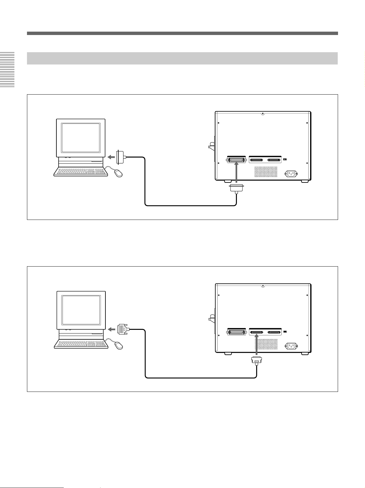
Connection Illustrations
Parallel Cable Connection
The UP-D6300, -D6400 and UP-D6500 connect to the computer by a parallel interface cable.
Introduction
UP-D6300/D6400/D6500
Personal Computer
Parallel Cable
Use an IEEE-1284 compatible parallel cable
Amphenol 36-pin
* The UP-D6300/D6400 do not include a SCSI connector and SCSI ID switch.
SCSI Cable Connection
The UP-D6500 can be connected to the computer by a SCSI cable. When using SCSI connections, other SCSI
devices such as an MO disk drive can be connected in between.
UP-D6500
Personal Computer
Half-pitch 50-pin
(pin end)
SCSI Cable
Use a SCSI-2 compatible SCSI cable
6 Introduction

Part Names and Functions
Front View
132
4
1 POWER Switch
This switch turns the printer on and off. When turned
on, the POWER ON lamp on the indicator panel lights
green.
2 Front Door
The ink ribbon cassette and cleaning roll holder are
installed behind this door. Pull on both sides of the
door to open it.
5
ba c
d Cleaning Roller Holder
The cleaning rollers install on this holder. Pull the
knob to remove it.
e Cleaning Rollers
The cleaning rollers are supplied with the printer.
When a card enters the printer, it passes between these
rollers to remove any dust from the card, so the rollers
should always be installed. Wash the rollers
periodically with water (page 27).
3 Indicator Panel Lamps
The panel lamps indicate the status of the printer.
fghijk
POWER ON ALARM RIBBON CARD PRINT READY
f POWER ON lamp (green)
This lamp is lit when the power is on.
g ALARM lamp (orange)
This lamp blinks when an error occurs, and lights
steadily when a fatal error occurs.
h RIBBON lamp (orange)
This lamp blinks when the ink ribbon supply is low,
and lights steadily when the ink ribbon reaches the
end.
Introduction
d
e
a Ink Ribbon Holder
An ink ribbon (sold separately) installs in the ink
ribbon holder.
b Bad Card Stacker
Bad cards are rejected here. Always remove any bad
cards before printing, and when the ALARM lamp
blinks.
c Cleaning Roller Cover
The cleaning rollers are installed behind this cover. To
open it, pull where it says PULL OPEN.
i CARD lamp (orange)
This lamp lights when the optional automatic card
feeder is installed. During manual-feed operation, this
lamp lights when the printer is waiting for a card.
j PRINT lamp (green)
This lamp lights while printing. During manual-feed
operation, this lamp blinks when the printer is waiting
for a card to be inserted.
k READY lamp (green)
This lamp blinks during warm-up, and when data is
being sent to the printer. This lamp light steadily when
the printer is ready to print.
Introduction 7
Part Names and Functions
4 Card Tray
Printed cards are ejected here.
Introduction
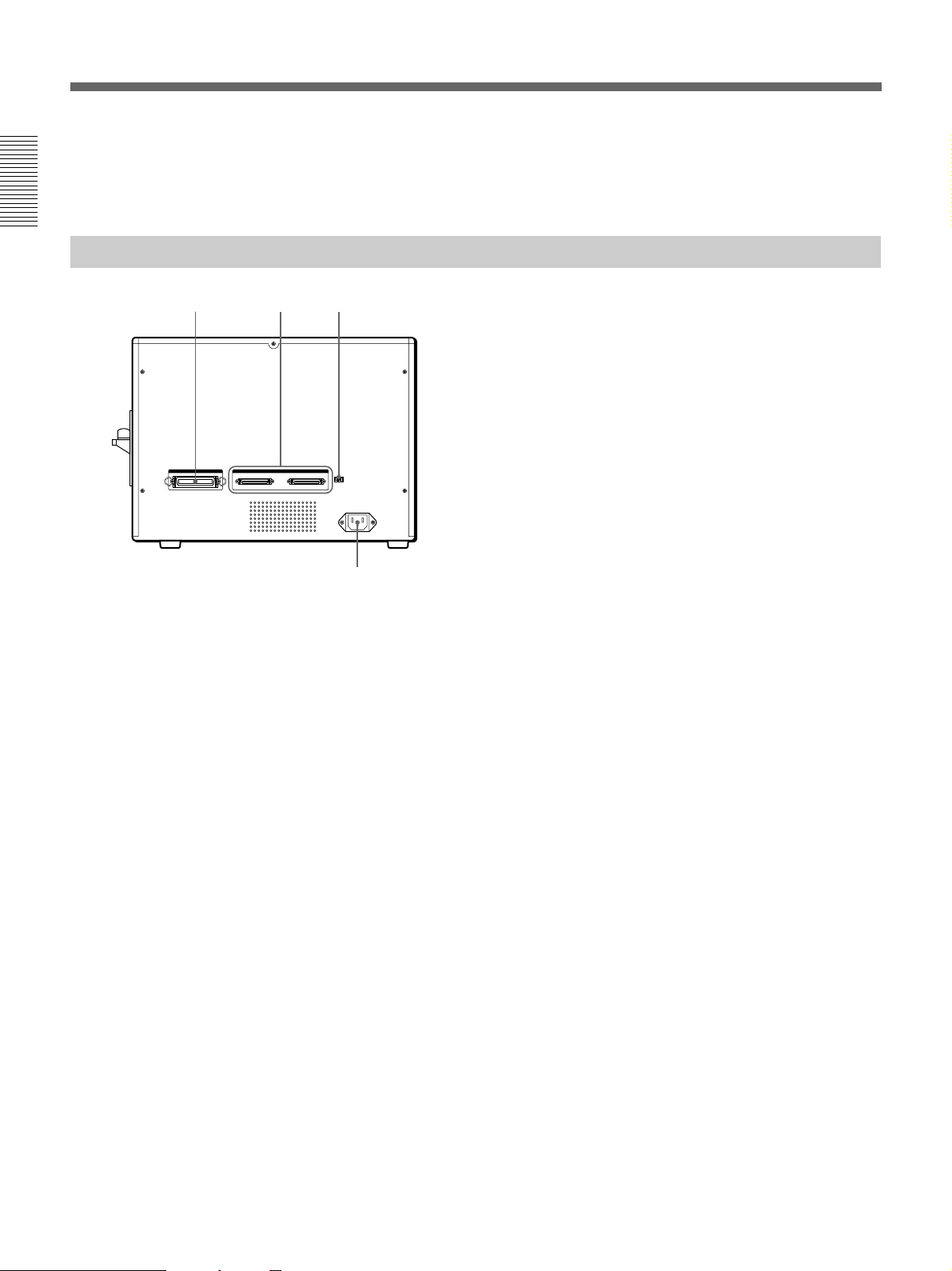
Rear View
5 Card Insertion Slot
Insert a card here for manual feed. The optional
automatic card feeder can also be installed here.
6 87
9
6 Parallel Interface Connector
Connect the parallel port of the controlling computer
here using a parallel interface cable.
7 SCSI Connectors (UP-D6500 only)
The SCSI connectors on the UP-D6500 can be used to
connect this model to the controlling computer and
other peripheral devices via a SCSI cable. The second
connector can be used to connect other SCSI devices
with this printer. However, if one of the connectors is
not used, set the terminator switch (leftmost SCSI ID
switch 8) to the ON position.
8 SCSI ID and SCSI Terminator switch
(UP-D6500 only)
This switch sets the SCSI ID for the printer. Also, if no
other SCSI devices are connected to the printer, so that
one of the SCSI connectors is unused, set the SCSI
terminator switch ON.
9 AC IN (Power Input) Socket
The supplied AC power cord connects here.
8 Introduction
Precautions
Operating Precautions
Power Supply
Connect only to the specified power source (120 or
240 VAC, 50/60 Hz).
Handle the Power Cord Carefully
Do not bend the cord sharply or place heavy objects on
it. The cord could be damaged and cause a fire or
electric shock. Do not use a damaged cord.
Avoid Ingress of Foreign Objects
Do not spill any liquids or drop any flammable or
metallic objects into the printer. Operating the printer
with a foreign object inside may cause fire, electric
shock or damage.
To Avoid Electric Shock
Never remove the outer cabinet. Touching internal
components may cause electric shock and presents
other dangers.
In Case of Abnormal Operation
In the event of an unusual sound or smell, or if smoke
appears or a foreign object falls into the printer, turn
off the power and contact your nearest Sony Service
Center.
If not Using for a Long Time
Turn off the power and unplug the power cord from
the outlet.
About Transporting
Remove all attached accessories before transporting
the printer. Transporting with accessories connected
may result in damage.
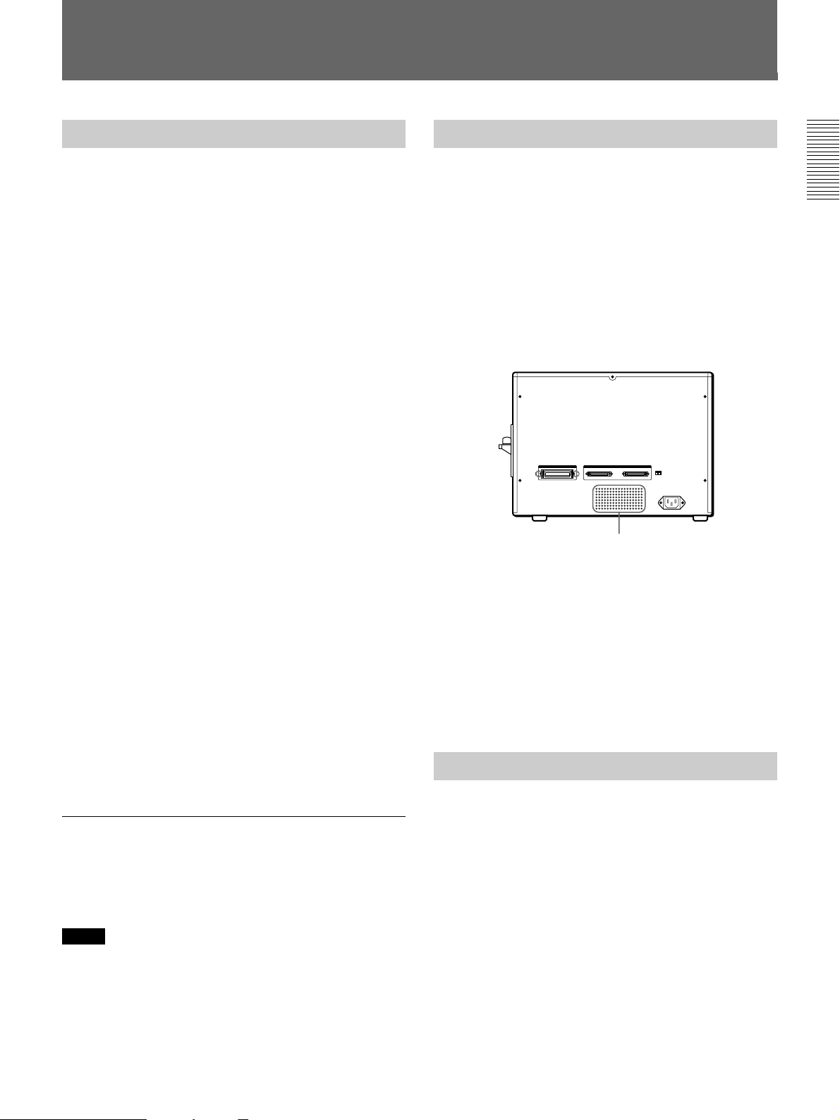
Installation Precautions
Do not install or store the printer in the following
conditions:
•Exposed to direct sunlight
•In humid locations
•In very hot or cold locations
•Where it might be exposed to heavy vibration
•Dusty locations
•On an unstable surface
•Avoid blocking the vent on the rear, as damage could
result.
Vent
About Condensation
If the printer is moved from a cool place to a warm
humid place, moisture may condense inside. Operating
the printer in this condition could cause a malfunction
and damage. Therefore, if any possibility of
condensation is suspected, the printer should be turned
off and allowed time to reach equilibrium with the
environment.
Cleaning
Introduction
About Card Stock
Use cards that comply with ISO international standard
(ISO7810 ID-1 type) or JIS standard (JIS X6301-
1979).
Notes
•Use only clean cards, with no debris, dirt or other
adhering matter.
•Some card materials may not be suitable. Contact
your supplier for details.
When the cabinet becomes dirty, wipe it with a cloth
moistened with water or a solution of synthetic
detergent (after wringing out any excess liquid). Do
not use thinner, cleaning fluid, alcohol or a chemically
treated cloth, as these could damage the cabinet finish.
Introduction 9
Preparation
Preparation
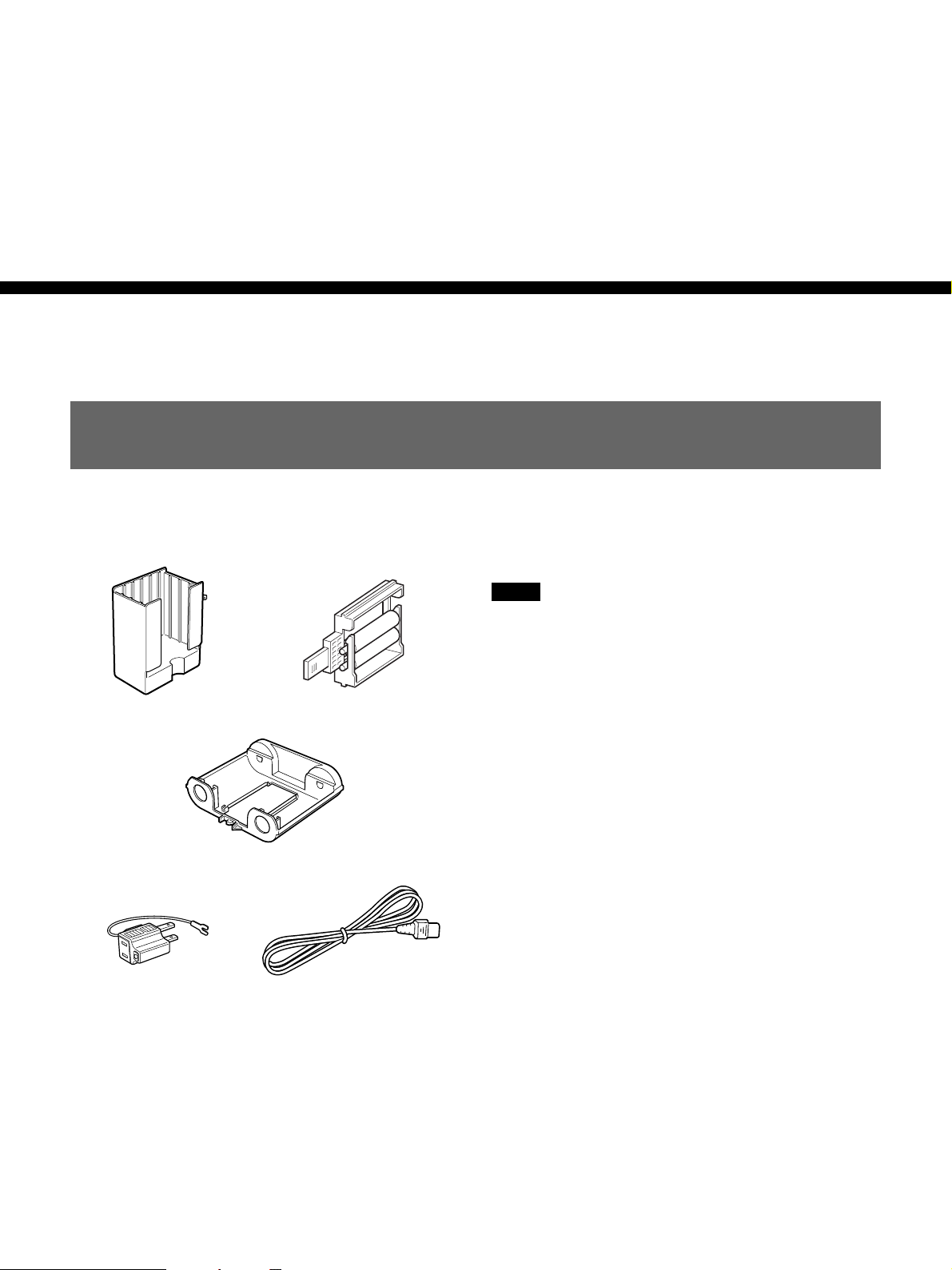
Supplied Accessories
Make certain you have received the following
accessories:
Card Tray (1) Cleaning Roller Holder (1)
Ink Ribbon Holder (1)
Operating Manual (1)
Floppy Diskette (1)
Notes
•The packing materials are needed when transporting
the printer, so we suggest you keep them.
•Before printing, be sure to remove the packing
material that immobilizes the head for transport.
AC Power Plug Adapter (1) AC Power Cord (1)
10 Preparation
Installing the Ink Ribbon Cassette
This procedure describes how to install the ribbon
cassette in the printer.
Before beginning, obtain the required ink ribbon (sold
separately). The following types of ink ribbon are
available:
Color ink ribbon 5UPR-6040: 3-color CMY and
laminate
Color ink ribbon 5UPR-6080: 4-color CMYK and
laminate
Black ink ribbon UPR-6025: black only
•The 5UPR-6040/6080 ribbons provide lamination
along with color printing.
The color ink ribbon package consists of five pieces
in one set. One roll of 5UPR-6040 can print about
250 single-sided cards, and one roll of 5UPR-6080
can print about 200 single-sided cards.
•The UPR-6025 ribbon package consists of one unit
which prints black only. About 1,000 single-sided
cards can be printed.
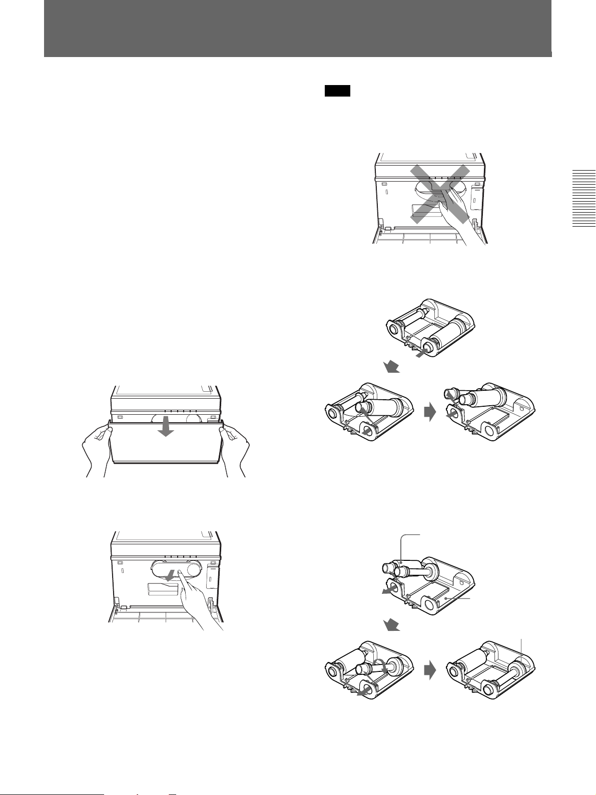
1 Hold both sides of the front door, and pull it down
to open.
Note
Do not touch the inside of the ink ribbon holder
compartment. The print head inside the printer may
be very hot.
Preparation
3 When changing the ink ribbon, remove the used
ribbon from the ribbon holder.
2 To change the ink ribbon, press on the part marked
PUSH to remove the ink ribbon holder.
When installing an ink ribbon in the printer the
first time, skip this step and proceed to step 4.
1 Remove take-up spool 2 Remove supply spool
When installing an ink ribbon in the printer the
first time, skip this step and proceed to step 4.
4 Install an ink ribbon in the ink ribbon holder.
1 Install the ink ribbon
supply spool.
2 Install the take-up spool.
Ink ribbon
Ink ribbon holder
Barcode ring
Preparation 11
Installing the Ink Ribbon Cassette
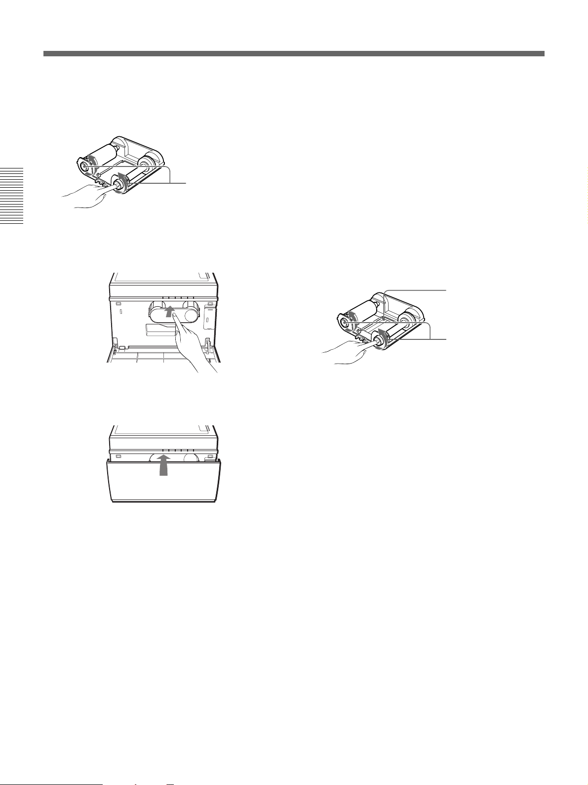
5 Take up any slack in the ribbon.
To avoid damage to the ribbon during installation,
take up the slack.
Turn the spools alternately
to remove slack.
Preparation
6 Insert the ink ribbon holder into its installation slot,
and push until it stops.
Handling Ink Ribbons
•Do not reuse ink ribbons.
•Do not touch the surface of a ribbon, or store it in a
dusty place. Fingerprints and dust may cause
degraded printing.
Storing Ink Ribbons
•Do not store ribbons in hot or humid places.
•To preserve a partially used ribbon, save it in the
humidity-resistant bag in which it was originally
supplied.
If a Ribbon Breaks
You can repair a broken ribbon with plastic tape so
you can use the remaining unused portion.
Repair with plastic tape
Take up slack ribbon
7 Confirm that the installation was done correctly,
and close the front door.
12 Preparation
Installing the Cleaning Rollers
This procedure describes how to install the cleaning
rollers in the printer.
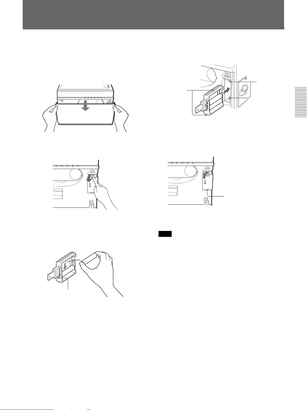
1 Hold both sides of the front door, and pull it down
to open.
2 Pull on the cleaning roller cover marked PULL
OPEN to remove the cover.
4 Insert the cleaning roller holder into the printer,
and push it until it stops.
Rail
Guide
Preparation
Align the top and bottom guides with the rails
when inserting.
5 Install the cleaning roller cover removed in step 2.
Insert the bottom edge of the
cover first, then push the top
edge.
3 Install two cleaning rollers into the cleaning roller
holder.
Be careful to avoid touching the roller surfaces, as
printing could be degraded.
Insert the roller axles into the slots.
When installing cleaning rollers in the printer the
first time, skip this step and proceed to step 4.
6 Close the front door.
Note
After using the cleaning rollers for a long time, their
cleaning ability will be degraded, causing colors to fail
to transfer properly to the printout. To avoid this, wash
the cleaning rollers each time after printing about 200
cards (page 27).
Preparation 13
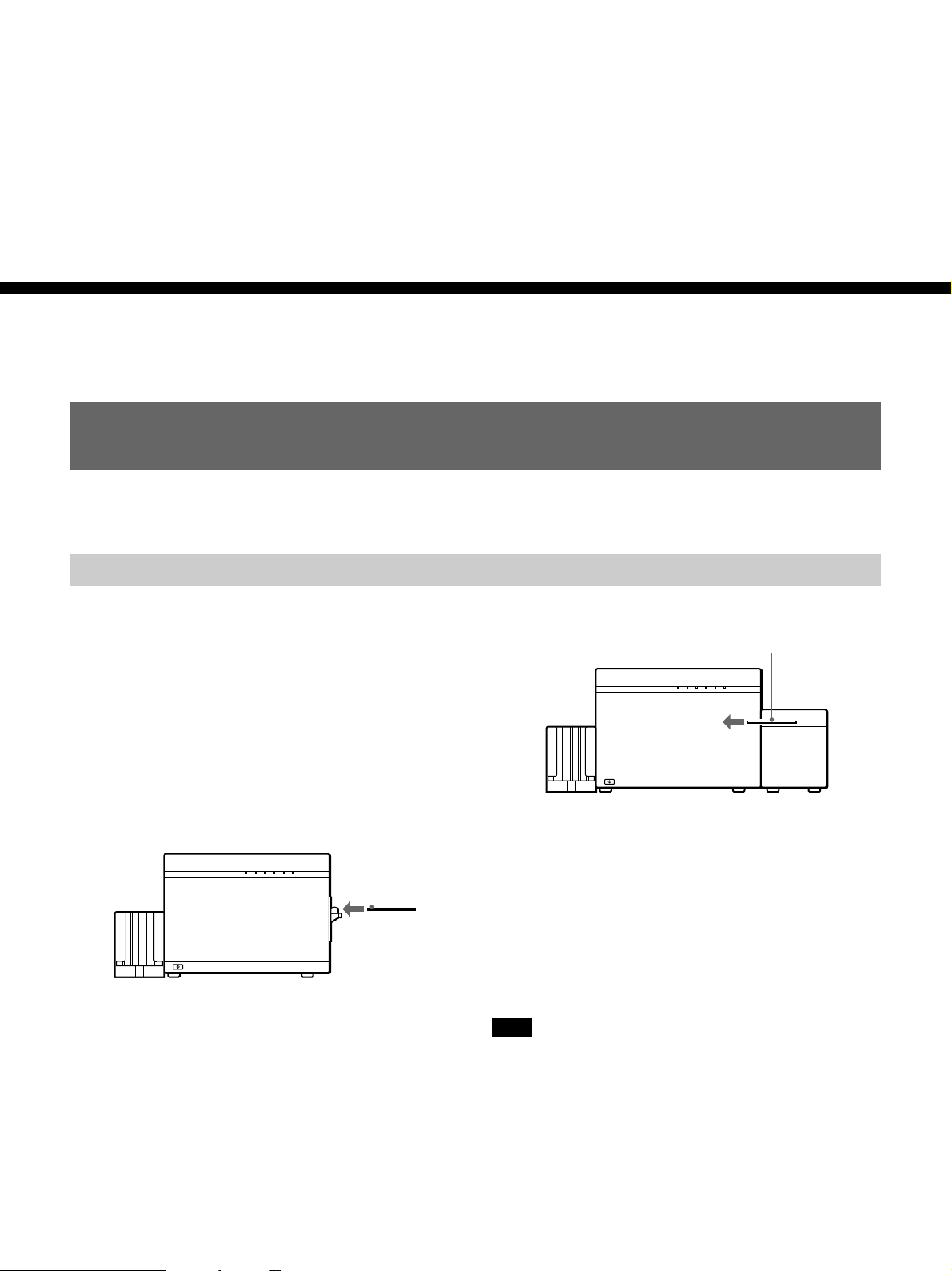
Installing the Card Tray
Printed cards are ejected into the card tray. Install the
card tray with this procedure.
When installing the optional Auto Card Stacker, the
card tray should be installed after the Auto Card
Stacker (page 16).
1 Insert the card tray hook into the insertion slot on
the printer.
Preparation
Hook
Card Tray
Using Optional Accessories
2 Pull the card tray down.
Pull down
Note
Be sure to pull the card tray down completely, or cards
may fail to eject and jam in the printer.
Optional accessories for these printer models include
the UPA-6003 Auto Card Feeder to automatically feed
cards to the printer when printing, and the UPA-6002
Auto Card Stacker to receive printed cards from the
printer.
Option Option
Supplied
card tray
UP-D6400/D6300/D6500 UP-D6500
UPA-6003 UPA-6003UPA-6002
Auto Card Feeder
Supplied
card tray
Continuously prints up to about 125 ISO
standard 0.76-mm-thick cards.
One Auto Card Feeder can be installed on the UPD6400/D6300, and up to two Auto Card Feeders and
one Auto Card Stacker can be installed on the UPD6500. The supplied card tray can also be installed
when the Auto Card Stacker is installed.
UPA-6003
Auto Card Stacker Auto Card Feeder
(1st Unit)
Auto Card Feeder
(2nd Unit)
Continuously prints up to about 250 ISO
standard 0.76-mm-thick cards.
14 Preparation
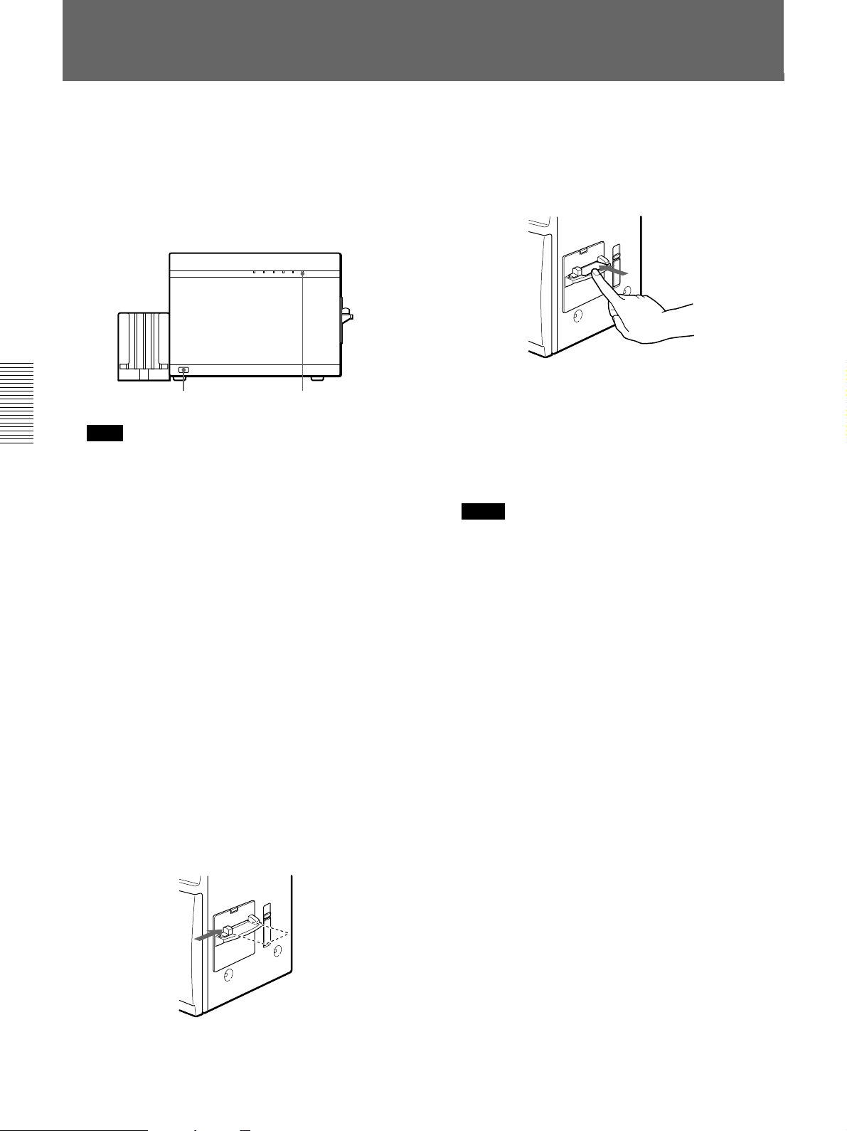
Installing the Auto Card Feeder
Note
Always turn off the power to the printer when
installing or removing options.
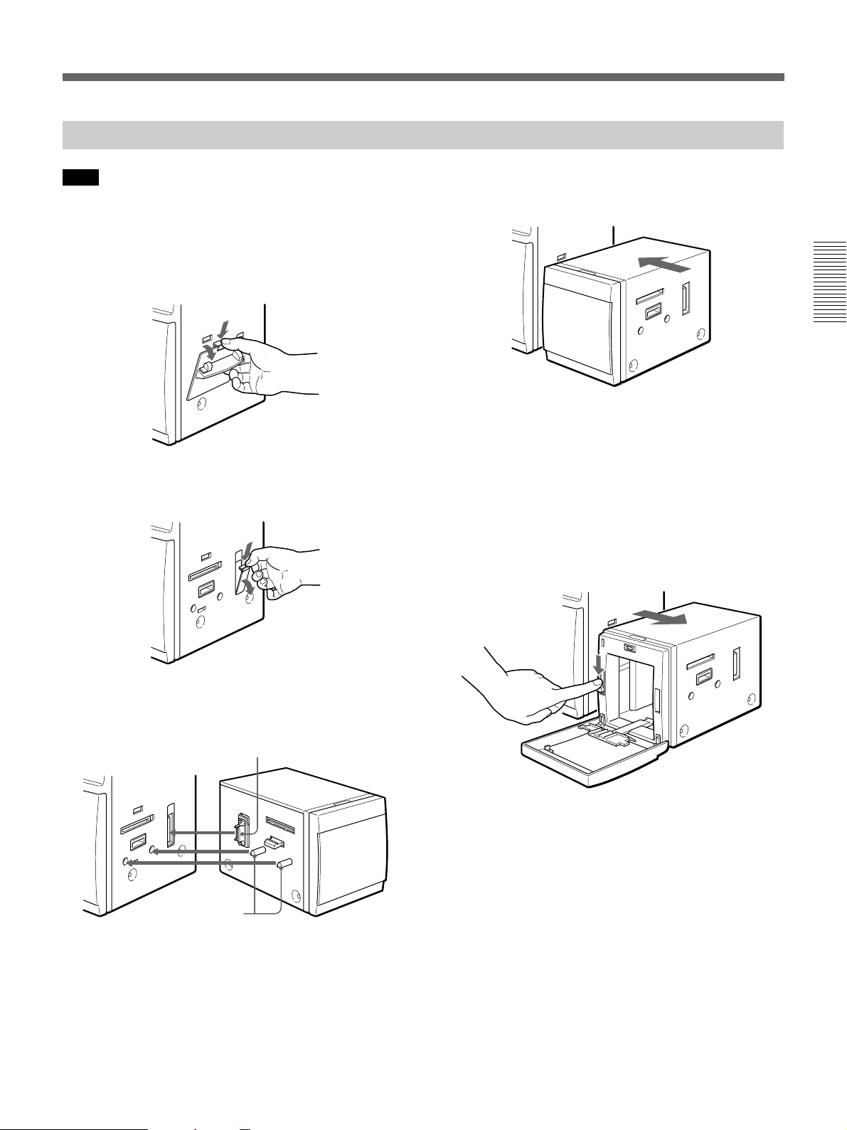
1 Remove the manual guide for the card insertion
slot while pushing up on the knob.
Remove the upper edge first,
then the lower edge
2 Push down on the upper knob and remove the
connector cover.
4 Push the Auto Card Feeder so the connectors mate
firmly.
Push firmly
Preparation
Installing a Second Feeder
A second Auto Card Feeder can be installed on the
UP-D6500. The second feeder installs on the outer side
of the first feeder, using the same procedure.
Removing the Feeder
To remove the feeder, open the feeder cover and push
down on the locking level while separating the feeder
from the printer.
Remove the upper edge first,
then the lower edge
3 Align and insert the connector and guide pins on
the Auto Card Feeder to the connector and guide
holes on the printer.
Align the connectors
Align the guide holes
Preparation 15
Using Optional Accessories
Installing the Auto Card Stacker
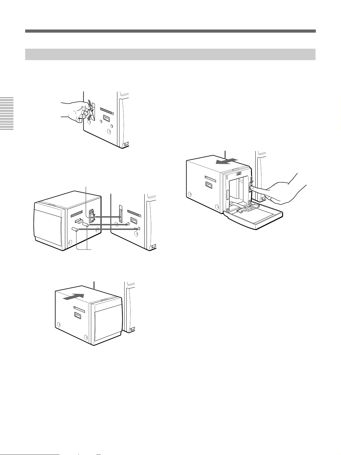
1 Push down on the upper knob and remove the
connector cover.
Preparation
Remove the upper edge first,
then the lower edge
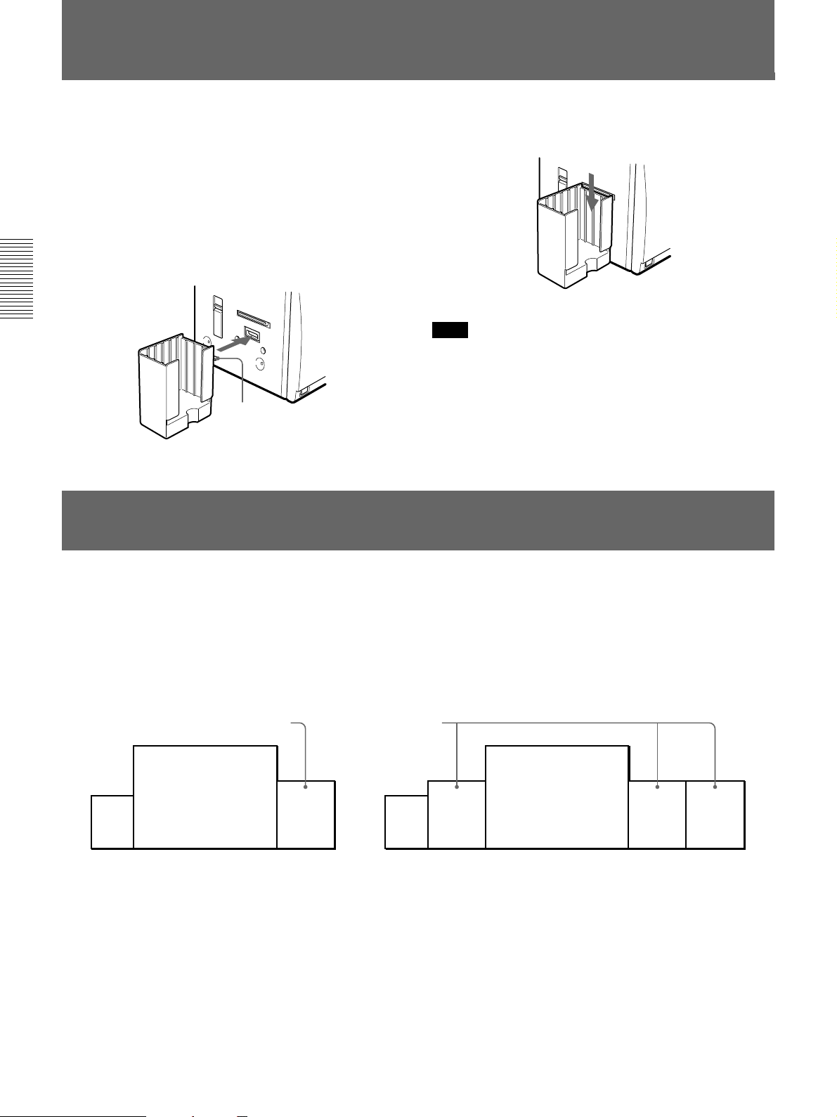
2 Align and insert the connector and guide pins on
the Auto Card Stacker to the connector and guide
holes on the printer.
Align the connectors
Also Installing the Supplied Card Tray
Install the supplied card tray after installing the Auto
Card Stacker. The card tray installs on the outside of
the Auto Card Stacker, using the same procedure as for
installing it on the printer (page 14).
Removing the Stacker
To remove the stacker, open the stacker cover and
push down on the locking level while separating the
stacker from the printer.
Align the guide holes
3 Push the Auto Card Stacker so the connectors mate
firmly.
Push firmly
16 Preparation
Connections
The following examples show the connection of the
system to print cards. The UP-D6500/D6400 and
D6300 are equipped with a parallel connector for
D6500 is also equipped with a SCSI connector, which
can be used with a SCSI cable instead of the parallel
connection.
connecting to the computer with a parallel cable. The
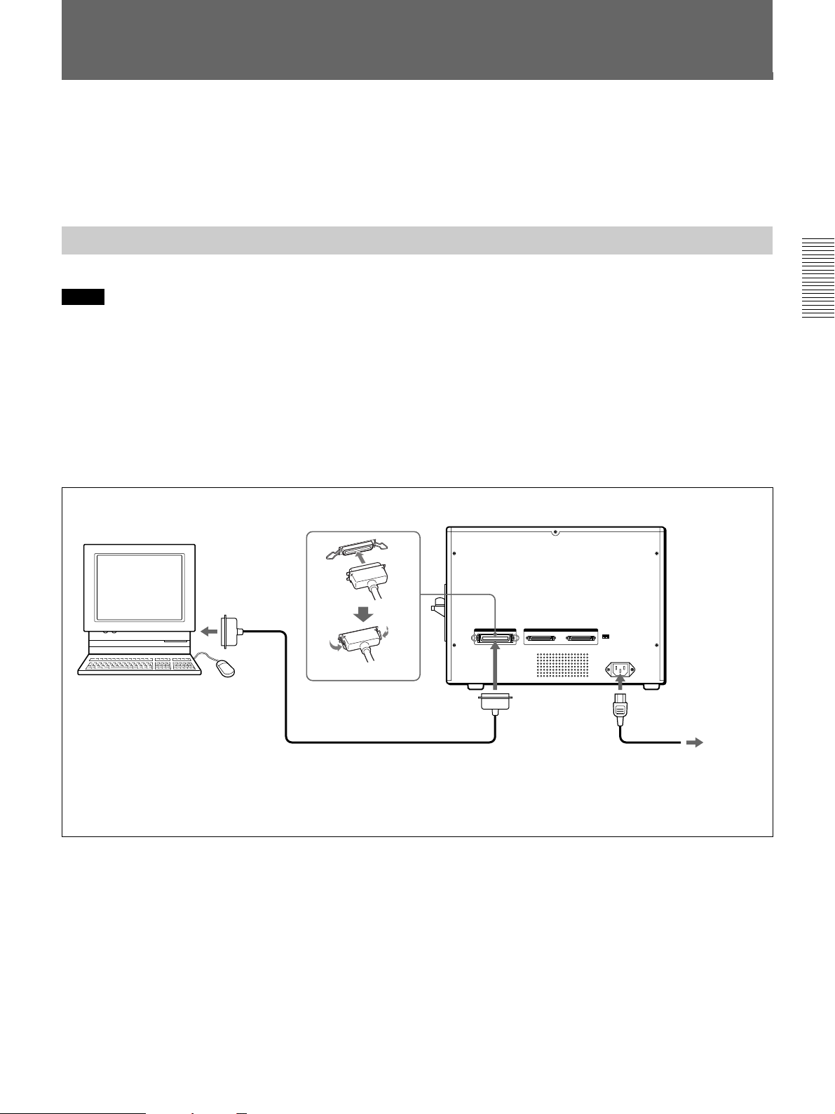
Parallel Cable Connection
Notes
•Turn off the power to all devices when making connections.
•Connect the power cords last.
•Insert the parallel data cable connector firmly, as far as it will go.
•The parallel cable should be no longer than 3 meters, and conform to the Centronics specification. However, the
type of connectors on the parallel cable depends on the computer and other peripheral devices being connected.
Refer to the operating manuals for the devices for details.
•To use the high speed drive mode (ECP mode), the cable should comply with IEEE1284, such as the Hewlett
Packard model C2950A.
•Do not use the SCSI interface when using the parallel interface.
Clip bail locks on both sides
Personal Computer
UP-D6300/D6400/D6500
Preparation
To parallel
connector
To AC IN
Parallel cable
1)
To parallel
connector
To power outlet
1) Use a parallel cable that complies with IEEE-1284. Refer also to the computer operating manual for the type of parallel
cable to use.
* The UP-D6300 and D6400 do not have SCSI connectors or a SCSI ID switch.
Preparation 17
Connection
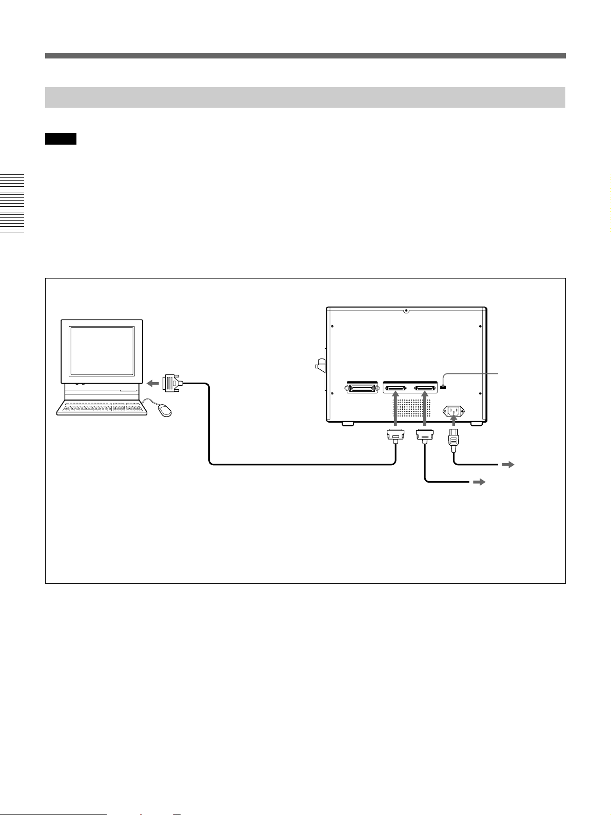
SCSI Cable Connection (UP-D6500)
Notes
•Turn off the power to all devices when making connections.
•Connect the power cords last.
•Up to seven peripheral devices can be connected to the SCSI bus.
•Refer to the operating manual for each device for details about peripheral device connections.
•Insert the SCSI cable connectors firmly, as far as they will go.
•The total length of the SCSI cable connected to one host computer should be no more than three meters.
•When only the printer is connected to one host computer, the SCSI cable length should be no more than one
Preparation
meter.
•Do not use the parallel interface when using the SCSI interface.
UP-D6500
Personal Computer
To SCSI
connector
SCSI ID
SCSI cable
To SCSI connector
1)
Connects to other devices, if needed.
To AC IN
To power outlet
2)
1) Refer to the computer operating manual for the type of SCSI cable to use. When connecting other SCSI devices, refer
also to the manuals supplied with those devices. Use a cable compatible with the SCSI2 standard.
2) The SCSI bus allows connection of other SCSI devices by daisy chain between the computer and printer, and after the
printer. Refer to the operating manuals of those devices for the settings on those devices.
3) For SCSI connections, the SCSI ID should be set by the SCSI ID switch (page 19). Also, if one of the SCSI connectors
on the printer is not used, set the leftmost (terminator) switch on the SCSI ID switches to ON (page 19).
18 Preparation
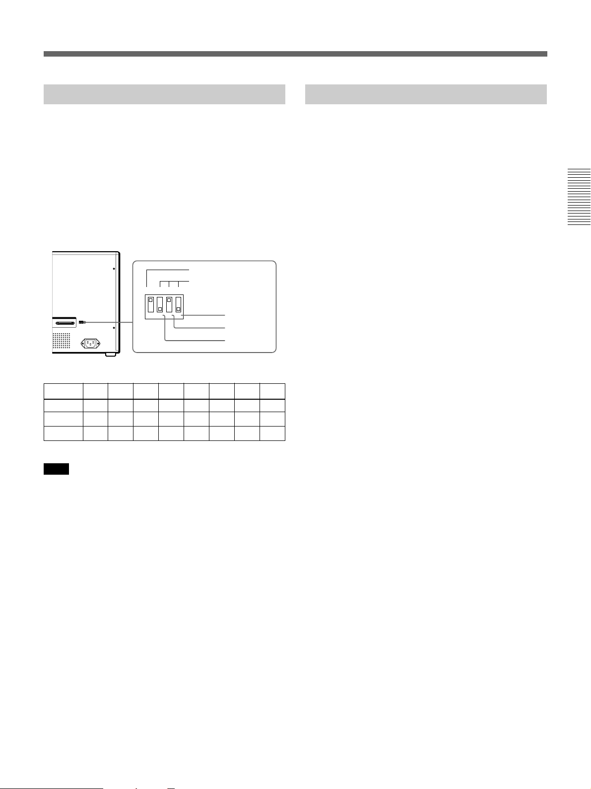
Setting the SCSI ID
Setting the Terminator
Up to seven SCSI devices can be connected to the
SCSI bus by daisy chaining. Each SCSI device is
recognized by its ID number, from 0 to 7.
Turn off the power to the printer, and set the printer ID
number with the SCSI ID switches on the rear, so that
it is unique from any other SCSI device. When shipped
from the factory, the SCSI ID is set to “2”.
The SCSI ID number is set by the combination of three
SCSI ID switch settings.
The SCSI ID consists of the sum of the ID
number of each switch that is turned on.
TERMINATOR
SCSI ID
124ON
1
432
000OFF
ID=0 ID=1 ID=2 ID=3 ID=4 ID=5 ID=6 ID=7
Switch 4 OFF ON OFF ON OFF ON OFF ON
Switch 3 OFF OFF ON ON OFF OFF ON ON
Switch 2 OFF OFF OFF OFF ON ON ON ON
Switch 4
Switch 3
Switch 2
The leftmost switch of the SCSI ID switches is the
terminator switch. Turning this switch on enables the
internal SCSI terminator.
If either of the SCSI connectors is not used in the
installation, turn the terminator switch ON.
Preparation
Note
When setting the SCSI ID, be careful not to duplicate
the number of another device on the SCSI bus. The ID
must be unique for each device.
Preparation 19
Printing
Before Printing
Printing
Confirm the feeding method and precautions before printing.
Feeding Method
The printing feeding method for cards depends on
whether the optional Auto Card Feeder is installed.
Before beginning, confirm the feeding method to be
used for printing.
Standard Case
If the optional Auto Card Feeder is not installed, feed
the cards manually one at a time after sending the print
command.
Feed manually after executing print command
Auto Card Feeder Case
If cards are placed in the Auto Card Feeder, the cards
are fed to the printer after sending the print command.
Cards are fed automatically at print time
If a second Auto Card Feeder is installed on the UPD6500, cards in the first Auto Card Feeder are fed
first, followed by those in the second Feeder when the
first is empty.
Cards can also be fed manually at the card insertion
slot of the Auto Card Feeder. However, do not insert
cards that are a different size from those in the Auto
Card Feeder, or a jam may result.
Note
Cards with fingerprints or dirt on their surface may
degrade printing. To avoid touching the surface, insert
a card by holding it at the edges.
We recommend using the Auto Card Feeder to
minimize the need to touch the cards.
20 Printing

Things to Know Before Printing
Confirm the following preparations have been
completed before printing a card:
•Connect the printer to a computer (page 17).
•If using the SCSI connection, set the SCSI ID (page
19).
•Install the ink ribbon (page 11), cleaning roller (page
13) and card tray (page 14).
•If you use an optional Auto Card Feeder (page 15) or
Auto Card Stacker (page 16), install these
accessories.
Note the following when handling cards:
•Hold cards by the edges, and avoid touching the
surface. Fingerprints on a card may cause dirty
printing or poor ink bonding.
•Soft cotton gloves are recommended when handling
large batches of cards.
•If using the optional Auto Card Feeder, fan the cards
thoroughly to ensure they do not stick together
before loading them into the Feeder.
•Do not store cards in a dirty place. Dirt on a card may
cause dirty printing or poor ink bonding.
•Insert cards with magnetic stripe so that the stripe
faces down and toward the rear.
Note the following when printing:
•Use an application program that supports the printer.
•Color adjustment of the printing image is
accomplished by the program.
•Print quantities are set by the program.
•When using cards with a magnetic stripe, set the
printing size to avoid printing onto the stripes. Even
if no actual image prints on the stripe it will be
laminated over if it is within the printing area, which
may cause later problems reading the strip.
Printing
Printing 21
Manual-Feed Printing
This procedure describes how to print by manually
feeding cards to the printer.
1 Turn on the printer.
The READY lamp blinks for a few seconds, then
lights steadily when ready to print.
Power switch Ready lamp
Note
Printing
When using the SCSI connection, do not turn the
printer on or off while the host computer is
accessing other SCSI devices, such as a hard disk.
2 Confirm the printer’s READY lamp is lit, then turn
on the computer. When using the SCSI connection,
turn on all other SCSI devices before turning on
the computer.
3 Send the image data from the computer. The
READY lamp blinks while the data is being sent to
the printer. Sent image data is temporarily stored in
the image memory of the printer.
6 Put a card in the insertion slot, and push it until
your finger touches the hollow area at the center of
the slot. Insert cards with magnetic stripes so that
the stripe faces down and toward the rear.
The card is pulled into the printer and printing
starts. After printing, the printer returns to the
standby condition.
7 When printing multiple cards, insert the next card
in the slot when one finishes printing.
Notes
•Do not open the front door, Auto Card Feeder
cover or Auto Card Stacker cover while printing.
Opening a cover stops printing.
•Do not put more than 125 cards in the supplied
card tray, as a jam could result.
•Printing cannot be aborted from the computer.
When the computer sends a command to stop
printing, the card being printed finishes before the
printer enters the waiting condition.
4 Send the Print command from the computer to start
printing.
The PRINT lamp on the printer lights.
Refer to the software documentation for details of
program operations on the computer.
5 Adjust the guides on the card insertion slot to
match the width of the cards to print.
22 Printing
To print the same image repeatedly
Send the Print command from the computer and insert
a card manually. The image data stored in the printer’s
image memory will be printed.
Printing with the Auto Card Feeder
This procedure describes how to print with the
optional Auto Card Feeder installed.
1 Turn on the printer.
The READY lamp blinks for a few seconds, then
lights steadily when ready to print.
Power switch Ready lamp
Note
When using the SCSI connection, do not turn the
printer on or off while the host computer is
accessing other SCSI devices, such as a hard disk.
2 Confirm the printer’s READY lamp is lit, then turn
on the computer. When using the SCSI connection,
turn on all other SCSI devices before turning on
the computer.
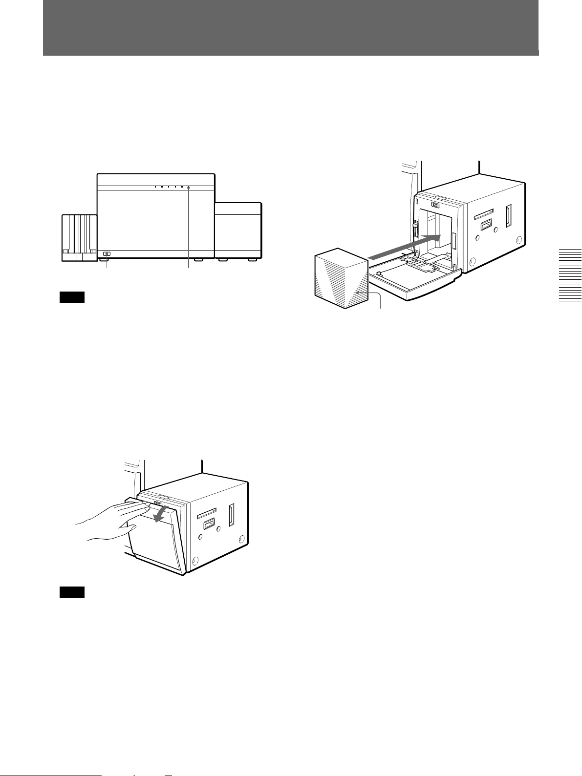
3 Hold the top of the Auto Card Feeder cover, and
pull it to open.
4 Put the cards on the platform inside the Auto Card
Feeder. Insert cards with magnetic stripe so that
the stripe faces down and toward the rear.
We recommend using soft cotton gloves to handle
cards, to avoid fingerprints and dirt.
Stack the cards neatly. Before placing,
massage the card stack to avoid sticking.
5 Close the Auto Card Feeder cover.
6 Send the image data from the computer. The
READY lamp blinks while the data is being sent to
the printer. Sent image data is temporarily stored in
the image memory of the printer.
7 Send the Print command from the computer to start
printing.
The PRINT lamp on the printer lights, and cards
are fed to the printer automatically as printing
begins.
Refer to the software documentation for details of
program operations on the computer.
After printing, the printer returns to the standby
condition.
Printing
Note
The platform inside the Auto Card Feeder lowers.
Be careful not to pinch your finger beneath it.
Printing 23
Printing with the Auto Card Feeder
8 When the Auto Card Stacker is installed, open the
Auto Card Stacker to remove printed cards.
Notes
•Do not open the front door, Auto Card Feeder cover
Printing
or Auto Card Stacker cover while printing. Opening a
cover stops printing.
•Do not store more than 125 cards in the supplied card
tray, as a jam could result.
•Do not put more than 125 cards in the Auto Card
Feeder, as a jam could result.
•If using the optional Auto Card Feeder, fan the cards
thoroughly to ensure they do not stick together
before loading them into the Feeder.
If cards stick together, they may not feed correctly. If
this occurs, turn the power off, remove the cards from
the Auto Card Feeder, unstack them and then return
them to the Feeder.
•Do not load different types of cards in the Auto Card
Feeder at the same time, as a jam could result.
•Do not move the printer with the Auto Card Feeder or
Stacker installed. Always remove the Auto Card
Feeder, Auto Card Stack and card tray before
moving the printer.
•Printing cannot be aborted from the computer. When
the computer sends a command to stop printing, the
card being printed finishes before the printer enters
the waiting condition.
To print the same image repeatedly
Send the Print command again from the computer. The
image data stored in the printer’s image memory will
be printed.
When the Auto Card Feeder runs out of cards
while printing
Reload the Feeder and send the Print command again.
If multiple copies of the same card are being printed,
the remaining number prints. Cards can also be
inserted manually into the card insertion slot on the
Auto Card Feeder.
Inserting cards manually
Even with the Auto Card Feeder installed, cards can be
inserted manually one at a time into the card insertion
slot on the Feeder. Insert a card before issuing the Print
command.
Be careful to avoid inserting a card that is not the same
size as those in the Auto Card Feeder, as a jam could
result.
24 Printing
Precautions During and After Printing
If you cannot print or a card becomes jammed, see the
following information. Bad cards that have
accumulated in the Bad Card Stacker inside the printer
should be removed periodically.
If you cannot print
•Printing is disabled if the ALARM lamp is blinking
(page 26).
•Turning the printer off deletes the image stored in the
printer’s image memory, so to resume printing, the
image data must be sent from the computer again.
An image must be sent to the printer memory before
sending the Print command, or printing cannot
1)
occur.
Note
Turning the printer power on returns the print quantity
setting to its default value of “1”.
If a card is jammed
The ALARM lamp blinks and one or two other lamps
are lit when a card is jammed inside the printer.
Turning the printer off and back on should cause the
jammed card to be transferred automatically to the Bad
Card Stacker.
If the card is not moved to the Bad Card Stacker,
contact your supplier or nearest Sony Service Center.
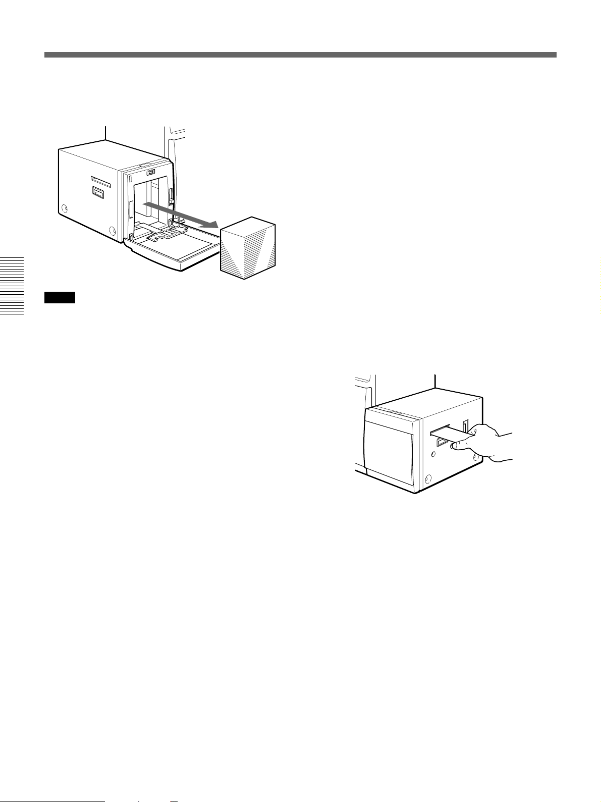
Removing bad cards
If only the ALARM lamp blinks, the Bad Card Stacker
is full. Open the front door and remove the bad cards.
Printing
..........................................................................................................................................................................................................
1) About Image Memory
Image data sent from the computer is stored in the image
memory. Data stored in the image memory can be
printed only by sending a Print command. The UPD6400/D6300 have 4 MB of memory, and the UPD6500 has 8 MB. The image transfer method and print
position are set at the computer side.
Printing 25
Appendixes
In Case of Problems
If you encounter a problem while using the printer, please check whether the following information can help you
fix the problem before contacting the Sony Service Center.
About Caution Indicator Lamps
Indicator lamps light or blink when an error occurs, to indicate the cause of the error. The table below shows the
Appendixes
various lamp error conditions and their corresponding remedies.
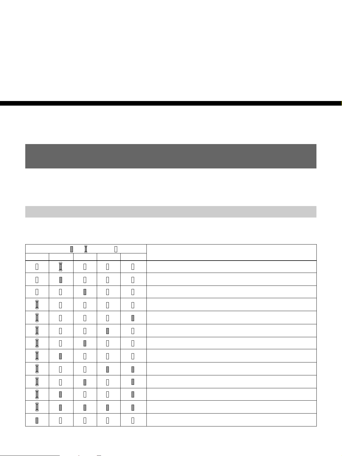
Lamp State ( =lit, =blinking, =off) Description/Remedy
ALARM RIBBON CARD PRINT READY
The ink ribbon is getting short.
→ Prepare a new ribbon.
End of ribbon.
→ Replace the ribbon (page 11).
The Auto Card Feeder is empty.
→ Add cards (page 23).
The internal Bad Card Stacker is full.
→ Remove the bad cards.
A card is jammed in the manual feeder.
→ Turn the power off and back on.
A card is jammed in the printing mechanism.
→ Turn the power off and back on.
A card is jammed in the card inverting mechanism.
→ Turn the power off and back on.
A card is jammed in the bad card ejecting mechanism.
→ Turn the power off and back on.
A card is jammed in the first Auto Card Feeder.
→ Turn the power off and back on.
A card is jammed in the second Auto Card Feeder.
→ Turn the power off and back on.
A card is jammed in the Auto Card Stacker.
→ Turn the power off and back on.
The print head is dead.
→ Replace the print head.
An error occurred that requires technical service.
→ Contact the nearest Sony Service Center.
1) Turning the printer off and back on should automatically remove a jammed card.
1)
1)
1)
1)
1)
1)
1)
26 Appendixes
If parts of the Image do not Print
If the adhesive capabilities of the cleaning rollers is
degraded so that dirt cannot be remove from a card,
non-printing areas (white spots) may appear. In such
cases, clean the cleaning rollers. We recommend
cleaning the cleaning rollers after printing about every
200 cards.
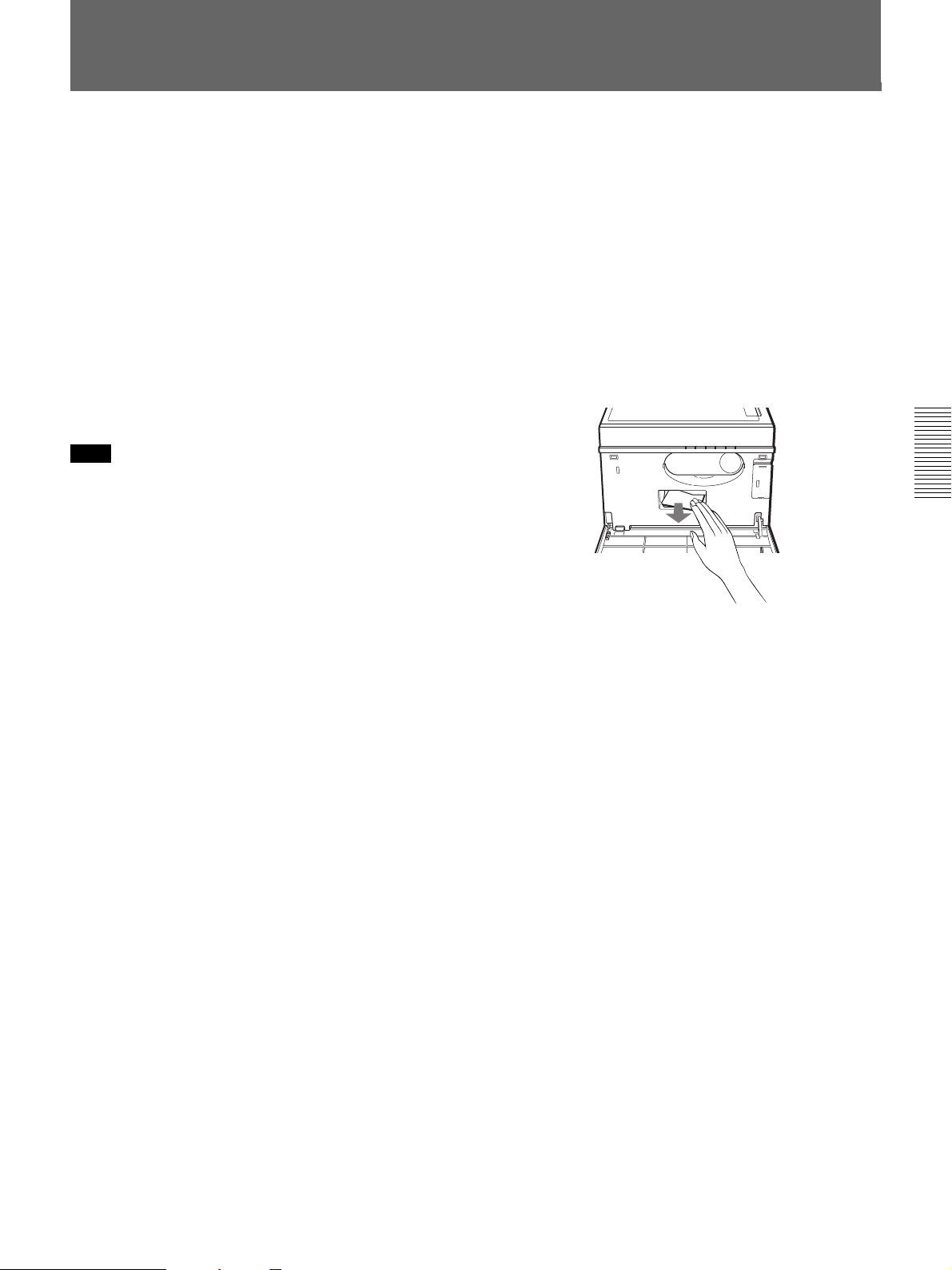
1 Hold both sides of the front door and pull it
towards you.
The front door opens.
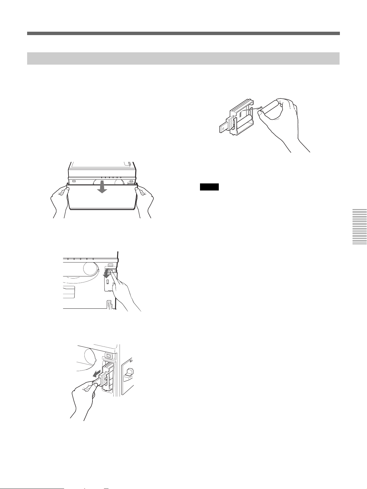
2 Pull on the part of the cleaning roller cover labeled
“PULL OPEN”, and remove the cover.
4 Remove the cleaning rollers from the cleaning
roller holder.
5 Wash the removed cleaning rollers with water, and
wipe completely so as not to attract dust.
Notes
•When wiping the cleaning rollers, make sure that
no cloth fibers remain on the rollers.
•Do not use synthetic detergent.
6 Replace the cleaning rollers as before, and close
the cleaning roller cover and the front door.
Appendixes
3 Pull the knob on the cleaning roller holder to
remove it.
Appendixes 27
Changing the Print Head
The print head is an expendable. After printing many
cards, or if dirty cards are printed often, the print head
may show signs of wear. If the ALARM lamp blinks
while the other four lamps (RIBBON, CARD, PRINT
and READY) are all lit, the print head must be
replaced. Use optional replacement print head model
UPU-D65H.
Notes
•Be sure to disconnect power from the printer before
changing the print head.
•The print head gets hot when printing, so before
changing the head, allow time for it to cool
sufficiently.
•Be sure to insert the connector to the print head
firmly.
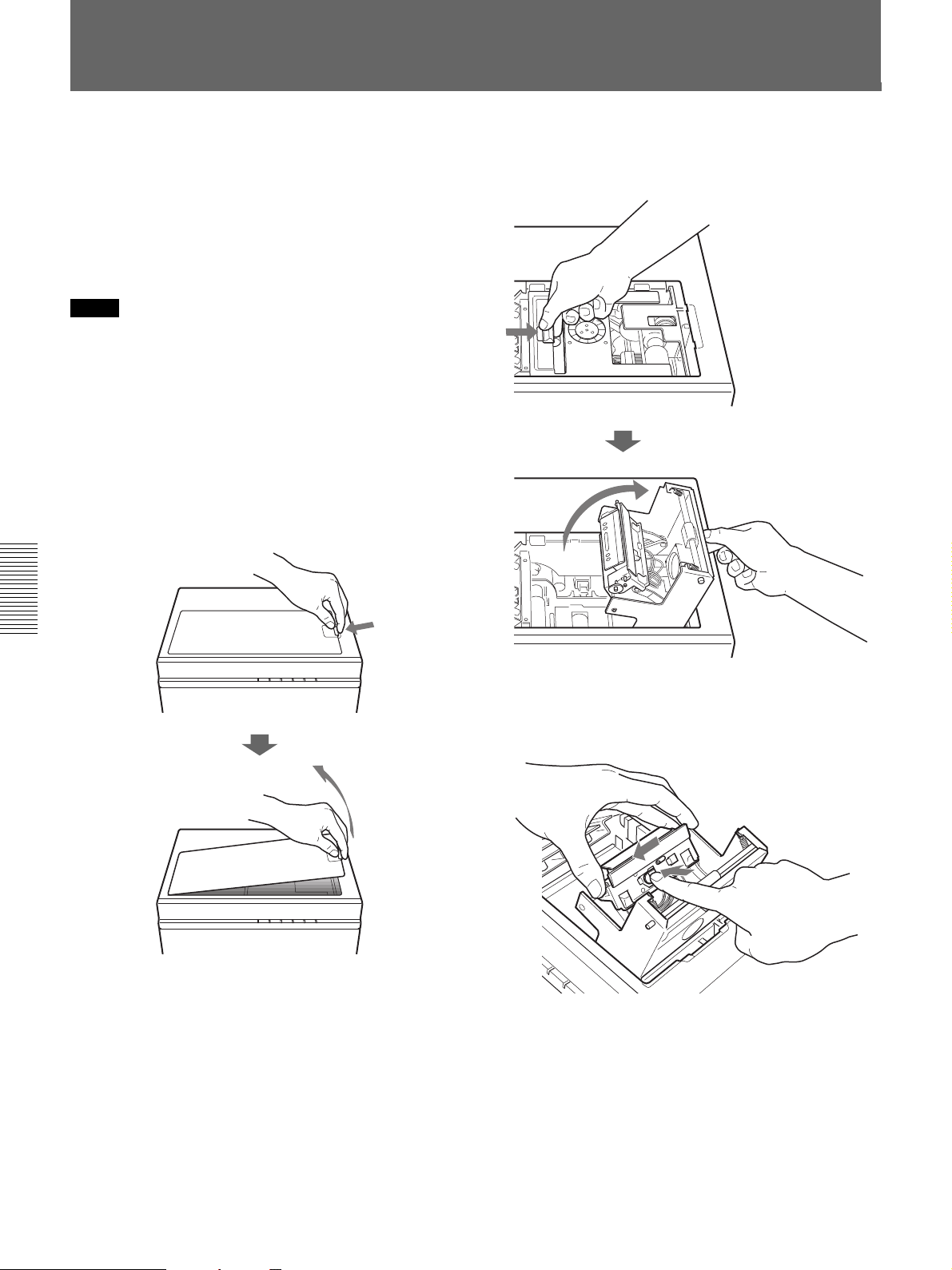
1 Push the top cover knob to the left, open the cover,
and remove it.
2 Pull the blue head holder lock in the direction of
the arrow, and pull the head holder up.
Appendixes
3 While pushing the blue lock button, move the print
head toward you, and remove the head holder from
its hooks.
28 Appendixes
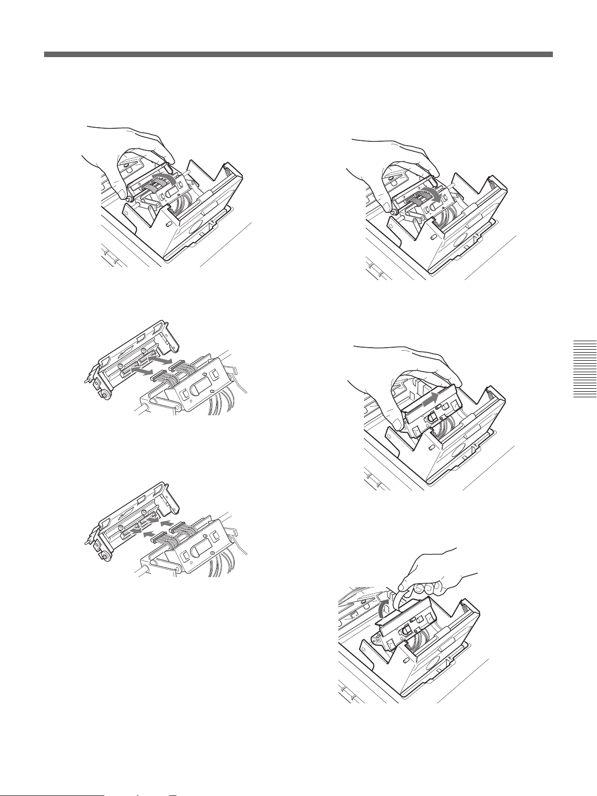
4 While pulling the print head up slightly, rotate it in
the direction shown in the figure.
5 Remove the two connectors at the rear of the print
head.
7 Roll the print head in the direction shown in the
figure so the holes in the print head align with the
hooks in the head holder.
8 Put the hooks in the head holder into the holes in
the print head, and move the print head back until
it locks.
6 Connect the connectors on the new print head in
place of those removed in step 5.
Appendixes
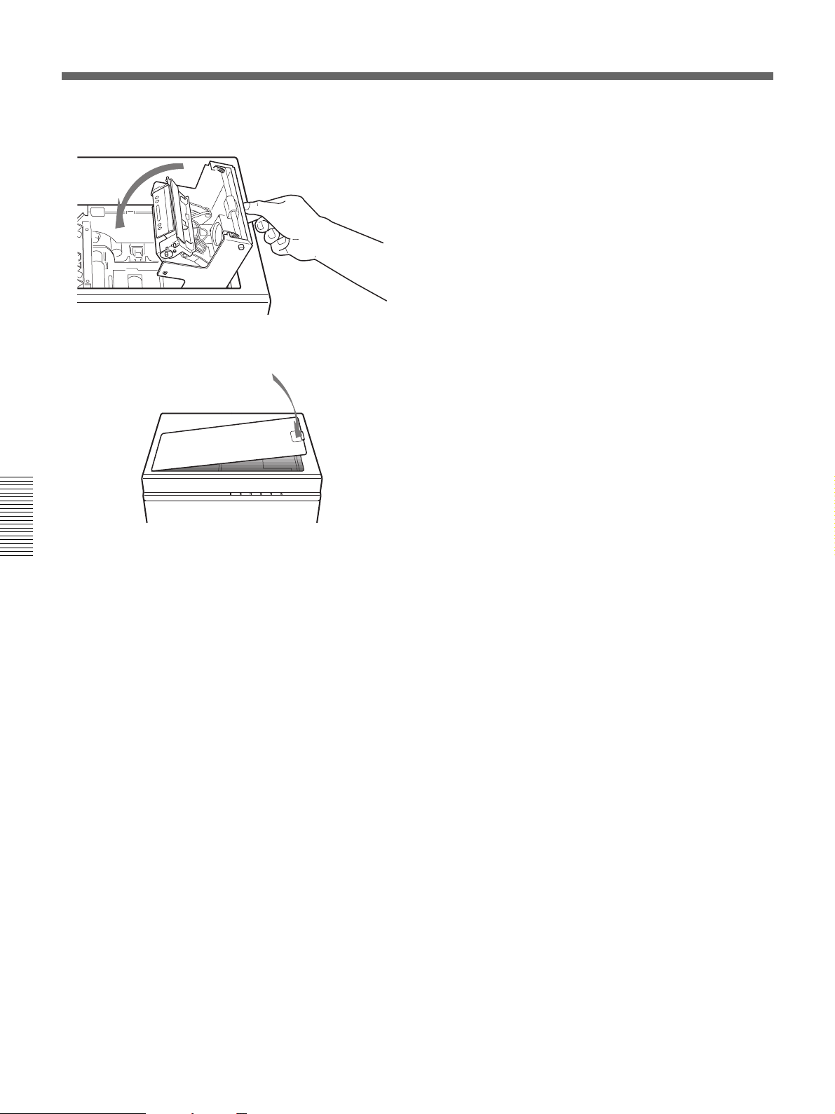
9 Remove the protective cover sheet from the head.
Appendixes 29
Changing the Print Head
10Replace the print head holder.
11Replace the top cover.
Appendixes
Insert the left side of the top cover first, then close
the right side.
30 Appendixes
 Loading...