

Page 1

3-207-489-11 (1)
Digital Color Printer
Instructions for Use
UP-D23MD
© 2003 Sony Corporation
Page 2
Owner's Record
The model and serial numbers are located at the rear.
Record these numbers in the space provided below.
Refer to these numbers whenever you call upon your
Sony dealer regarding this product.
unplugging the power cord from the unit), try these
measures: Relocate the unit with respect to the
susceptible equipm ent. Plug this unit and the
susceptible equipment into different branch circuit.
Consult your dealer. (According to standard
EN60601-1-2 and CISPR11, Class B, Group 1)
Model No. ____________________
Serial No. ____________________
WARNING
To prevent fire or shock hazard, do not expose
the unit to rain or moisture.
To avoid electrical shock, do not open the
cabinet. Refer servicing to qualified personnel
only.
THIS APPARATUS MUST BE EARTHED.
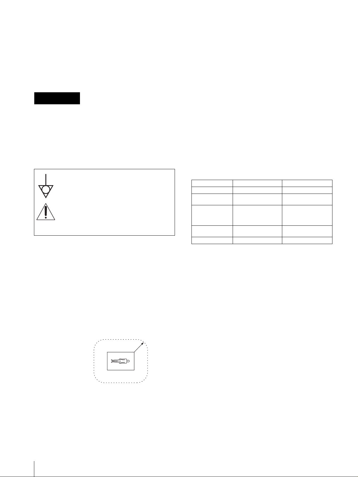
This symbol indicates the equipotential
terminal which brings the various parts of a
system to the same potential.
This symbol is intended to alert the user to
the presence of important operating and
maintenance (servicing) instructions in the
literature accompanying the appliance.
Important safeguards/notices for use in
the medical environments
1. All the equipments connected to this unit shall be
certified according to Standard IEC60601-1,
IEC60950, IEC60065 or other IEC/ISO Standards
applicable to the equ ipments.
2. When this unit is used toget her with other equ ipment
in the patient area*, the equipment shall be either
powered by an isol ation transformer or connected via
an additional protective earth terminal to system
ground unless it is certified according to Standard
IEC60601-1.
* Patient Area
Caution
When you dispose of the unit or accessories, you must
obey the law in the relative area or country and the
regulation in the rela tive hospital.
Warning on power connection
Use a proper power cord for your local power supply.
Warning on power connection for
medical use
Please use the following power supply cord.
With connectors (plug or female) and cord types other
than those indicated in this table, use the power supply
cord that is approved for use in your area.
United States Canada
Plug Type HOSPITAL GRADE* HOSPITAL GRADE*
Female end E62405, E35708 LR53182, LL022442,
Cord type E159216, E35496
Minimum cord set
rating
Safety approval UL Listed CSA
*Note: Grounding reliability can only be achieved when the equip-
ment is connected to an equiv alent recepta cle mark ed ‘Hospit al Only’
or ‘Hospital Grade’.
Min.Type SJT
Min.18 AWG
10A/125V 10A/125V
LL088408
LL112007-1, LL20262,
LL32121, LL84494
Min.Type SJT
Min.18AWG
R1.5m
3. The leakage current could increase when connected
to other equipment.
4. This equipment generates, uses, and can radiate
frequency energy. If it is not installed and used in
accordance with the instruction manual, it may cau se
interference to other equipment. If this unit causes
interference (which can be determined by
2
Page 3

For the customers in the U.S.A.
This equipment has been tested and found to comply
with the limits for a C lass A digital device, pursuant to
Part 15 of the FCC Rules. These limits are designed to
provide reasonable protection again harmful
interference when the e quipment is operated in a
commercial environment. This equipment generates,
uses, and can radiate radio frequency ener gy and, i f not
installed and used in accordance with the instruction
manual, may cause harmful interference to radio
communications. Operation of this equipment in a
residential area is likely to cause harmful interference in
which case the user will be required to correct the
interference at his own expense.
Y o u are cautioned that any c hanges or modif ications not
expressly approved in this manual could void your
authority to operate this equipment.
This device requires shielded interface cables to comply
with FCC emission limits.
For the customers in Canada
This unit has been certif i ed accor ding t o St anda rd CSA
C22.2 NO.601.1.
3
Page 4

Table of Contents
Getting Started
System Overview ................................................... 5
System Configuration .........................................5
Location and Function of Parts and Controls .... 5
Front Panel .........................................................5
Rear Panel ..........................................................6
Supplied Accessories ............................................. 6
Assembly ............................................................ 7
Connections ............................................................7
USB Port Connection ......................................... 7
Installing the Printer Driver ................................. 8
Operation
Before Printing ......................................................9
Loading an Ink Ribbon ...................................... 9
Loading Paper ..................................................11
Printing .................................................................12
Miscellaneous
Precaution ............................................................ 14
Safety ...............................................................14
Installation ........................................................14
Before Transporting the Printer ........................ 14
Cleaning ........................................................... 15
Ink Ribbon and Paper .........................................15
Specifications .......................................................16
Troubleshooting ................................................... 17
Indicators on the Front Panel .............................17
If the Paper Jams .................................................18
Index ..................................................................... 21
4
Page 5
Getting Started
Location and Function of Parts and Controls
System Overview
The UP-D23MD digital color printer is designed to
reproduce computer images on A-6 size paper.
Y ou can print out computer image data in full color (with
256 shades per color, a total of more than 16,700,000
colors in all) in high resolution print mode
(approximately 403 dpi).
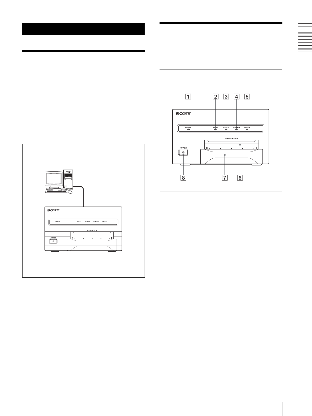
System Configuration
The following shows an example of a printer system
configuration.
Computer
Controls the printer operation.
For details, refer to the pages given in parentheses.
Front Panel
A POWER indicator
Lights when th e POWER s witch of the prin ter is set
to ON.
Getting Started
Digital color printer
B PRINT indicator (17)
Lights while the printer is printing.
C ALARM indicator (17)
Lights in orange in case of paper jamming or
occurrence of any other problem.
D RIBBON indicator (17)
Lights when a problem for ink ribbon occurs.
E PAPER indicator (17)
Lights when a problem for paper occurs.
The printer allows you to check the printer
operating condition according to the lighting
conditions of the PR INT indicator, ALARM
indicator , PAPER indicator and RIBBON i ndicator.
For details, see “Indicators on the Front Panel” on
page 17.
System Overview / Location and Function of Parts and Controls
5
Page 6
F Paper output slot
Printed pages are ejected here.
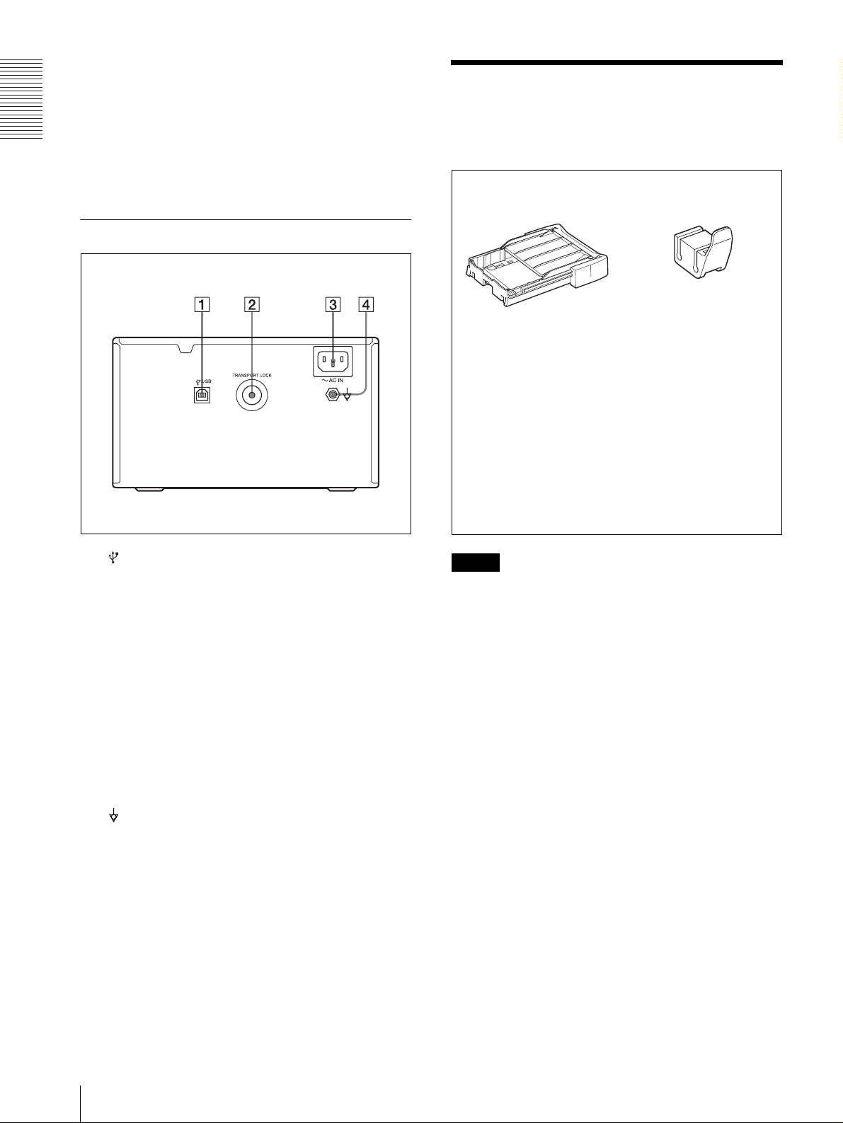
Supplied Accessories
G Paper tray (7)
Load paper into th is tr ay.
Getting Started
The printer is packed together with the following
accessories. Check that nothing is missing from your
package.
H ! POWER switch (12)
Press this switch to turn th e printer on or off.
Paper Tray (1)
Stopper (1)
Rear Panel
USB connecting cable (1)
Software Licence Agreement (1)
CD-ROM (1)
Thermal head cleaning cartridge (1)
Before Using this Printer (1)
A (USB) connector (7)
Connects to a computer or another USB peripheral
device with a USB cable (supplied).
B TRANSPORT LOCK button (14)
Press this button to secure the int ernal thermal head
when transporting the printer.
C - AC IN connector
Use a proper power cord for your local pow er
supply (not supplied).
Refer to “Warning on power connection” and
“W arning on po wer connection for medi cal use” on
page 2.
D Equipotential ground terminal connector
Used to connect to the equipotential plug to bring
the various parts of a system to the same po te ntial.
Refer to “Important safeguards/notices for use in
the medical environments” on page 2.
Notes
• Retain the original carton and packing materials in
case you have to transport th e unit in the future.
• Rem o ve the ink ribbon cartridge and paper t r ay when
transporting th e printer.
• When transporting the printer, secure the thermal
head. (For detailed information on how to secure it,
see “Before Transporting the Printer” on page 14.)
6
Supplied Accessories
Page 7
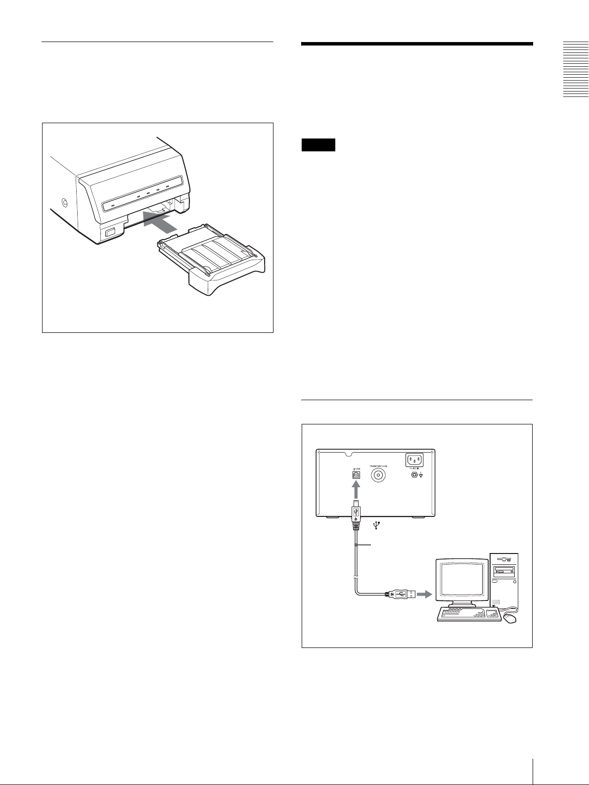
Assembly
To attach the paper tray
For details of how to load the ink ribbon and paper, see
“Loading an Ink Ribbon” on page 9 and “Loading
Paper” on page 11.
Paper tray
Connections
After connecting the USB connecting cable (supplied)
to the printer and the computer, connect the power cord.
For details about the printer connection, refer to the
manuals for the computer or other peripheral devices.
Notes
• Before connecting the printer to the comp uter, turn off
the printer, computer, monitor, and all peripheral
devices connected to the computer.
• Before connecting the printer to the computer,
disconnect the power cord from the printer. Connect
the power cord to the printer only after connecting the
printer and the computer.
• The printer is provided with a USB interface that can
be connected to any computer equipped with a USB
interface.
• Follow the connection procedures described in the
computer manual.
• Make sure that the interface cable is connected
securely at both ends.
• The printer drive software provided with the printer is
not suitable for using the printer connected to a
network.
• Operation of the printer is not guaranteed for
connection to a USB hub.
Getting Started
USB Port Connection
to (USB) connector
USB connecting
cable
Connections
7
Page 8

Installing the Printer
b)
If your OS is Windows98/ME, up to Full-speed
USB is supported.
Driver
Getting Started
Install the printer driver provided with the printer. For
detailed instructions on how to install the printer driver,
refer to the Readme.txt file on the printer driver installer
disc.
Note
When the UP-D23MD is connected to the computer
with the power turned on, do not turn your computer to
standby mode (suspend st atus) or in pause mo de. Doing
so may cause a malfunction of the operation.
About USB (Universal Serial Bus) Specification
Revision 2.0
• The UP-D23MD complies with the USB 2.0
specification.
• USB 2.0 is a newer standar d than USB 1. 1, but
provides backward compatibility.
• USB 2.0 supports Hi-speed USB, in addition to the
existing Full (Low) speed.
• The UP-D23MD can be connected as Full-speed in a
USB 1.1 environment. However, to use the UPD23MD with Hi-speed USB functions in a USB 1.1
environment, the following requirements must be met.
– Computer
A computer which supports Hi-speed USB
(conforming to the USB 2.0 specification)
–OS
Window s2000/XP
– USB 2.0 device driver
USB 2.0 device driver produced by Microsoft
Corporation. (Operation using USB 2.0 drivers
other than ones produced by Microsof t Corporation
is not guaranteed.)
– USB 2.0 cable
Use the 2-m cable supplied with the UP-D23MD.
b)
a)
a)
Operations of all of de vices which conf orm to USB
2.0, or all USB 2.0 extension boards/extension
cards cannot be guaranteed.
8
Installing the Printer Driver
Page 9

Operation
Before Printing
This section describes the operations below that must be
made before printing, bu t after mounting the paper tray
on the printer (see “Assembly” on page 7) and after
making the necessary connections (see “Connections”
on page 7).
• Loading an ink ribbon (See below.)
• Loading paper (See page 11.)
Once the above operations have been completed, there
should be no need to repe at them during rout ine printing.
Perform them only as necessary.
Notes
• You can replace the ink ribbon or load paper
regardless of whether the po wer is on or off . Howev er,
turning off the power will cause the image stored in
the memory to be lost.
• Use the ink ribbon and paper contained in the same
package as a pair. Before attempting to load an ink
ribbon or paper , make sure that the combinati on of the
ink ribbon and paper is compatible. When either an
ink ribbon or paper has been exhausted, replace both
the ink ribbon and paper at the same time.
• Use only ink ribbon and paper designed for use with
this printer. Failing to do so is likely to result in
malfunctions. (See“Ink Ribbon and Paper” on page
15.)
• Do not touch the ink ribbon or place it in a dusty
location. Finger prints or dust on the ink ribbon will
result in imperfect p rinting or mal function of the head.
• Use the ink ribbon and paper supplied with the
printer for the initial operation check of the
printer.
1
Open the front panel by pulling the front panel
toward you.
Note
Be sure not to open the front panel when printing.
2
Remove the spent ink ribbon.
When you use the printer for the first time, this
operation is not required.
Operation
Loading an Ink Ribbon
Load an ink ribbon into the printer’s ink ribbon
compartment.
Notes
• When you use the printer for the first time, the
thermal he ad may be out of position. Before
attempting to use the ink ribbon, turn on the power
under the condition where the fron t panel is closed
so that the thermal head is placed at the correct
position.
• When transporting the printer, remove the ink ribbon
and secure the thermal head.
• If a blank sheet of paper is ejected, and the RIBBON
indicator lights, the ink ribbon has been exhausted.
Replace the paper together with the ink ribbon. Do not
reuse the ejected blank paper.
• Once an ink ribbon has been completely used up,
replace it. An ink ribbon is not reusable.
• Do not rewind the ink ribbon for reuse.
Before Printing
9
Page 10

Operation
3
Remove any slack from the ink rib bon.
Note
If the ribbon is l ef t slack, it may be damaged when
inserted.
Wind the spools in the
direction of the arrow until the
start position marker appears
as illustrated.
4
Load the new ink ribbon into the ink ribbon
Start position marker
compartment.
while you are printing or cleaning the internal
thermal head.
Push the point marked
“PULL OPEN”.
When storing ink ribb on cartridge:
• Avoid placing the ink ribbon in a location subject to:
– high temperatures
– high humidity
– excessiv e dust
– d irect sunlight
• Store a partially used ink ribbon in its original
packaging.
Insert the hole of the
handle of the ink
ribbon over the
protruberance of the
printer.
5
Close the front panel by pushing the point marked
with “PULL OPEN”.
If your ink ribbon should tear
Repair the tear with transparent tape. There should be no
problem with using the remaini ng p ort ion of the ribbon.
Transparent tape
Turn the spools in the direction of the arrow to
remove any slack until the transparent tape
cannot be seen.
10
Note
Be sure to close the front panel completely. If you
do not, a paper jam or a malfunction may occur
Before Printing
Page 11

Loading Paper
To load paper, follow the procedure below. Be careful
not to touch the printing surface.
Notes
• Use only paper recommended. Failing to do so is
likely to result in malfunctions such as paper jams.
(See “Ink Ribbon and Paper” on page 15.)
• When a blank sheet of paper is ejected and the
RIBBON indicator lights, the ink ribbon has been
exhausted. Replace the paper together with the ink
ribbon. Do not use the ejected blank paper.
1
Remove the p aper tray.
• Do not place different types of paper i n the tray at
the same time.
Set the paper securely
under the tab.
Riffle the paper with
the protection sheet.
Operation
Place the paper
along with the
protection sheet
in the paper tray
with the printing
surface facing
up.
Front
Partition
2
Place the paper in the paper t ray so that the printing
surface faces up with the protection sheet on top.
When the UPC-21L printing pack is used: Lay
the partition down.
When the UPC-21S prin tin g pack i s used : Raise
the partition.
Notes
• The paper tray holds up to 50 sheets of paper
when the UPC-21L printing pack is used and 80
sheets of paper when the UPC-21S printing pack
is used.
• When handling the paper, do not touch the
printing surface. Dust or finger prin ts are likely to
cause unsatisfactory printing or malfunction of
the head. Grasp the paper b y t he p rint ing surface
protection sheet.
• When loading the paper , l oad t he pap er so that it
lays flat in the paper tray. If the paper is curled, it
will overflow from the paper tray and paper may
not be fed properly. Be sure to riffle the paper
along with the protection sheets before
attempting to place the paper in the paper tray.
3
Remove the protection sheet placed on the top of
the paper.
4
Slide the paper tray back into the printer until it
clicks into place.
When storing the paper
• Avoid storing the paper in a location subject to:
– high temperatures
– high humidity
– excessive dust
– direct sunlight
• Use the original package for storing unused paper.
Attaching the stopper
When multiple printouts are being ejected, printouts
accumulated on the paper tray may be pushed out of the
paper tray when a new printout is ejected.
Before Printing
11
Page 12

Operation
T o pre v ent them from b eing pu shed, attach the suppl ied
stopper as illustrated.
Insert the edge of the paper tray into this groove.
v
Printing
Before printing
• Ensure that the printer is properly connected to the
computer.
• Ensure that the ink ribbon and paper are properly
loaded.
• Ensure that the printer driver has been installed.
POWER indicator
PRINT ind ic a to r
ALARM indicator
RIBBON indicator
PAPER indicator
Note
Do not leave more than 1 0 sheets of ejected printouts o n
the paper tray. Doing so may cause a paper jam.
1
1
Press the POWER switch to turn the printer on.
The POWER indicator ligh ts.
PRINT , ALARM, RIBBON and PAPER indicators
light at the same time, then all of them go out.
Notes
• Turn the printer on first.
• Do not turn the computer off and on while it is
accessing a hard or floppy disk.
2
Turn on the power of the computer.
3
Execute the print job with software application.
While the printer is receiving the image data from
the computer, the PRINT indicator blinks.
While the printer is printing, the PRINT indicator
lights.
Note
• Do not turn off th e power during printin g. If you do so,
paper may not be ejected and may jam in the printer.
• Do not pull the paper out till the printer finishes
printing.
• You can make multiple copies of identical printouts.
However, the printer may stop printing for various
reasons. In such a case, remove the printouts
12
Printing
Page 13

accumulated on the paper tray. The printer will start
automatically to print the remaining copies.
If the printer does not print
The printer will fail to print when the ALARM, P APER,
and/or RIBBON indicator light.
For details, see “Indi cat ors on the Front Pan el” on page
17.
If the paper or ink ribbon runs out during
printing
The printer stops th e printing operation.
Load the paper into the paper tray and the ink ribbon.
Printing of remaining copies is automatically started.
When storing your printouts
• A void storing the printout i n a location subject to high
temperatures, high humidity , excessi ve dust and direct
sunlight.
• Do not stick tape on a printout. Also, avoid leaving a
plastic eraser on a printout or placing a printout in
contact with materials which contain plasticizer
(under a desk mat, for example).
Operation
Printing
13
Page 14

and may even dev el op a fault if you per sist in using it .
Miscellaneous
Precaution
Safety
• Operate the printer using the power source specif ied in
“Specifications” on page 16.
• Be careful not to damage the AC power cord by
placing or dropping hea vy objects on it; it is dange rous
Miscellaneous
to use the unit with a damaged AC power cord.
• If you do not intend to use the unit for a long time,
disconnect the AC power cord.
• Unplug the AC power cord by grasping the plug, not
the cable itself.
• Do not disassemble the unit.
• Do not remove the cover. There is a danger of electric
shock from the internal parts.
• Be careful not to spill water or other liquids on the
unit, or to allow combustible or metallic mate rial to
enter the cabinet. If used w ith foreign matter in the
cabinet, the unit is liable to fail, or present a risk of fire
or electric shock.
• V entilation holes are provided to prevent the unit from
overheating. Be careful no t to obstruct them with other
units or by covering the unit with a cloth, etc.
• If the unit malfunctions or if a foreign body falls into
the cabinet, disconnect the AC power cord
immediately and consul t y our Sony service facility or
your Sony dealer.
Installation
• Avoid placing the unit in a l oc ation subject to:
– mechanical vibration
– high humidity
– excessive dust
– direct or excessive sunlight
– extremely high or low temperatures
• Do not use other electronic equipment near the unit.
The unit will not work properly in strong
electromagnetic fields.
• Do not place a heavy object such as a monitor on the
printer.
If condensation forms, turn off the power and leave the
printer to stand for at least one hour.
• If the printing pack is subjected to wide or sudden
changes in temperature, condensation may form on
the ink ribbon or paper. This will cause the printer to
malfunction. Also, if the p rinting pack is used in this
state, spots are likely to appear on the printout.
Therefore, av oid storing t he printing pac k in locatio ns
subject to wide or sudden changes of temperature.
• To store a half-used printing pack, replace it in its
original packing and reseal the package. If possible,
keep the sealed printing pac k i n a cool , d ark l oca tion.
To subsequently use the printing pack, place it, in its
sealed package, in a warm room for several hours.
Doing so prevents condensation from forming when
the printing pack is removed from its package.
Location
To prevent internal heat built-up, leave enough room
around the printer for air to circulate through the vents
on the left hand side and top of the cabinet.
Before Transporting the Printer
Before transporting the printer, use the following
procedure to remove the supplied accessories and then
put them back into their o riginal packing. Transporting
the printer with the supplie d accessories still installed
may cause malfunctions.
1
Remove the ink ribbon and the paper tray.
2
Secure the internal thermal head, as follow s:
1 Turn on the printer.
2 Press the TRANSPORT LOCK button on the
rear panel of the printer.
The PRINT, ALARM, RIBBON and PAPER
indicators are blin king and the printer operation
tone keeps sounding for about two seconds.
3 When the printer operation tone stops
sounding, turn off the power of the printer.
The thermal head is now secured.
To release the thermal head
Turn on the printer again. The thermal head moves so
that you can now install the ink ribbon again.
Condensation
• If the printer is subject to wide or sudden changes in
temperature, such as when it is moved from a cold
room to a warm room or when it is left in a room with
a heater that tends to produce large amounts of
moisture, condensation may form i nside the printer . In
such cases the printer will probably not w ork properly ,
14
Precaution
Page 15

Cleaning
Note
Be sure to turn off the power of the printer before
cleaning.
Ink Ribbon and Paper
Both paper and an ink ribbon are ne cessary for printi ng.
Use the ink ribbon with the paper contained in the same
package.
Cleaning the cabinet
Clean the cabinet, panel and controls with a soft dry
cloth, or a soft cloth lightly moistened with a mild
detergent soluti on. Do not use an y ty pe of solv ent , such
as alcohol or benzine, which may damage the finish.
Cleaning the thermal head
Clean the thermal head with the thermal head cleaning
cartridge (supplie d) if the printout quality deteriorates,
for example, when the white stripes begin to appear on
the printout.
It is recommended that you clean the thermal h ead after
every 10 p acks of paper to keep the print out quality at i ts
best.
1
Remove the paper tray and remove the paper.
2
Place the cleaning sheet in the paper tray so that the
shiny surface faces down.
Notes
• Be sure to use the cleaning sheet supplied with
the UPC-21L/21S color printing pack.
• Do not reuse the old cleaning sheet.
UPC-21S Color Printing Pack
Contains color ink ribbon cartridge and paper.
Color ink ribbon, 3 rolls
90 × 100 mm (3 5/8 × 4 inches) size paper , 1 packag e (80
sheets) × 3
UPC-21L Color Printing Pack
Contains color ink ribbon cartridge and paper.
Color ink ribbon, 4 rolls
100 × 144 mm (4 × 5 3/4 inches) size paper, 1 package
(50 sheets) × 4
Note
If the paper has been exhausted, replace the ink ribbon
together with the paper.
Miscellaneous
3
Load the cleaning cartridge into the ribbon
compartment.
Immediately after you load the paper tray with the
cleaning sheet and cleaning cartridge, the RIBBON
indicator goes off and the printer starts cleanin g the
thermal head automatically.
When the printer has completed cleaning the
thermal head, the RIBBON indicator goes on agai n.
Note
When you load the cleaning cartridge into the ink
ribbon compartment with the printer’s power on,
the printer starts cleaning.
If the printer i s not tu rned on, e ven t hough you turn
on the power after loading the cleaning cartridge,
the printer will not start cleaning.
Ink Ribbon and Paper
15
Page 16

Protection against harmful ingress of
Specifications
Power requirements
100 to 120 V AC, 50/60 Hz
(for 100 to 120 V AC users)
220 to 240 V AC, 50/60 Hz
(for 220 to 240 V AC users)
Input Current 1.8 A max. at 25°C
(for 100 to 120 V AC users)
1.0 A max. at 25°C
(for 220 to 240 V AC users)
Operating temperature
5°C to 35°C (41°F to 95°F)
Operating humidity
Miscellaneous
Storage and transport temperature
Storage and transport humidity
Dimensions Approx. 212 × 125 × 395 mm (w/h/d)
Mass Approx. 6.5 kg (14 lb 5 oz)
Printing system Sublimat ion heat transfer printing
Printable pixels When using the UPC-21S and printing
Total gradation 256 levels each for yellow, magenta,
Printing time When using the UPC-21S:
Thermal head 15.87 dots/mm
(USB) connector
Input connector AC IN (for power input)
Supplied accessories
Optional accessories
Medical Specifications
20% to 80% (no condensation allo wed)
–20°C to 60°C (–4°F to 140°F)
20% to 90% (no condensation allo wed)
(8 3/8 × 5 × 15 5/8 inches)
the full-image: 1520 × 1144 dots
When using the UPC-21L and printing
the full-image: 2000 × 1520 dots
and cyan
When the printer is set to high
speed: Approximately 19 seconds
When using the UPC-21L:
When the printer is set to high
speed: Approximately 29 seconds
Universal Serial Bus (USB)
Specification Revision 2.0
Paper tray (1)
USB connecting cable (1)
Thermal head cleaning cartridge (1)
Stopper (1)
Software License Agreement (1)
Before Using this Printer (1)
CD-ROM (1)
UPC-21L Color Printing Pack
UPC-21S Color Printing Pack
Protection against electric shock:
Class I
Design and specifications are subject to change without
notice.
water:
Ordinary
Degree of safety in the presence of
flammable anesthetics or oxygen:
Not suitable for use in the presence
of flammable anesthetics or oxygen
Mode of operation:
Continuous
16
Specifications
Page 17

Troubleshooting
Indicators on the Fr ont
The following troubleshooting checks will help you
correct the most common problems you may encounter
with your unit. Before proceeding with these trouble
checks, first check that the power cord is firmly
connected. Should the problem persist after you have
applied the remedy, unplug the unit and contact your
Sony dealer or local authorized Sony service facility.
Symptoms Possible caus es and reme dies
The printer does not
print, even if the
command is sent
from the computer.
The printer does not
print.
The printout color is
very pale.
The ink ribbon cannot
be loaded.
The blank paper is
ejected and the
RIBBON indicator
lights.
• The POWER switch of the printer is
not set to ON.
tSet the POWER switch of the
printer to ON.
• Connections may not be correct.
tCheck connections and rectify, if
necessary. (See page 7.)
The problem is in dicated by the
indicators on the front panel.
tSee “Ind icators on the Front Panel”
on page 17.
The paper is not loaded correctly.
tCheck which side of the paper is the
printing side, then load the paper
again. (See page 11.)
• You may be trying to load an ink
ribbon that can not be used with this
printer has been l oaded.
tLoad the appropriate ink ribbon.
(See page 15.)
• The thermal is secured.
tTurn on the printer. The therm a l
head moves so that you can now
install the ink ribbon. (See
page 14.)
The ink ribbon has been exhausted. Do
not reuse the ejected blank paper.
tReplace the ink ribbon. (See pages 9
and 11.)
Panel
If a problem occurs, the indicators on the front panel
such as PRINT , ALARM, RIBBON and/or P APER light
or blink to indicate the probl em condition. the follo wing
table shows the relation between lighting or blinking
condition of each indicator and possible cause and
remedies.
Indicators Possible cause and
Lighting Blinking
PRINT Printing
PRINT Data receiving
PRINT
(In this case,
it blinks
slowly.)
RIBBON • The ink ribb on has been
PAPER • Paper has been exhau s ted.
ALARM and
PAPER
ALARM and
RIBBON
remedies
The thermal head is being
heated so that the printer is
ready to start.
exhausted.
tReplace the old one with
a new ink ribbon. (See
page 9.) (The ink ribbon
cannot be reused.) In this
case, if the white paper is
ejected. Discard this
paper.
• The ink ribbon has torn.
tRepair the torn ink
ribbon. (See page 10.)
tLoad the paper. (See
page 11.) Also, replace
the ink ribbon.
• The paper tray is not
installed.
tInstall the paper tray.
(See page 7)
The ink ribbon and paper are
not compatible.
tUse the ink ribbon and paper
contained in the s ame
package. (See page 15.)
The wrong ink ribbon and the
paper are loaded when
replacing them bec a use the ink
ribbon and/or pa per run out
during printin g.
tLoad the same ink ribbon
and paper as ones used
before replacing with new
ones.
Miscellaneous
Troubleshooting / Indicators on the Front Panel
17
Page 18

Indicators Possible cause and
Lighting Blinking
ALARM • The front panel is open.
remedies
tClose the front door
surely.
• Paper has jammed inside the
printer.
tRemove any jammed
paper from the printer.
(See page 18.)
• The maximum number of
printouts has ac cu m ula t e d
on the paper tray.
tRemove the printouts.
Printing starts again.
If the Paper Jams
If the ALARM indicator li ghts on the f ront panel , or the
message “Paper jam. Printing is aborted. Please remov e
the jammed paper and print again.” or “Motor or sensor
trouble. Printing is aborted after you press the PRINT
button and during printing. Please turn off the printer,
then turn it back on and print again.” appears on a
monitor of a computer during printing after you press
the PRINT button, the paper may have jammed inside
the printer.
Remove the jammed paper according to the process
described below.
Miscellaneous
Note
If you turn off the power of the printer, any images
stored in memory will be lost. After you finishing the
following ope rations and turning on the printer on agai n,
recapture the image into memory,
1
Remove the paper tray.
If any printouts have been ejected onto the paper
tray and have accumulated on the paper tray,
remove them before removing the paper tray.
18
If the Paper Jams
2
Check whether any paper is jammed inside the
printer. If you find a jammed sheet, slowly pull it
straight out.
Page 19

If you cannot remove the jammed paper e ven if you
perform the operation in step 2, remo ve the jammed
paper according to instructions described in the
following “ If you can not re move the jammed paper
yet”.
3
Load the paper into the paper tray correctly.
Set the paper securely
under the tabs.
Notes
• Do not reuse the jammed paper. Discard that
paper.
• Use only paper recommended in this manual.
4
Remove the two screws with which the back cover
plate is se cured, using a coin.
5
Pull the back cover p late up and remov e it from the
printer.
Miscellaneous
4
Re-insert the removed paper tray.
If you can not remove the jammed paper yet
Precautions
• Turn the pr inter power of f and remove the power cable
from the printer. However, any images stored in
memory will be lost when yo u turn the printer off.
After finishing the following operations and turning
the printer on again, recapture the image into memory .
• When yo u turn the printer over, remove any
connecting cables. If cables are broken or bent, this
may cause fire or electrical shock.
• When you remove th e jammed paper , be careful not t o
injure your finger s when touching th e parts in side the
printer.
1
Be sure to set the power switch of the printer to off
and remove the power cable and other connecting
cables.
2
Remove the paper tray from the printer.
3
Turn the printer over.
6
Remove the jammed paper slowly , turning the gear
slowly in the direction of the a rrow.
If you still cannot remove the paper
Do not try to remove it forcibly. Contact your
nearest Sony dealer.
If the Paper Jams
19
Page 20

7
Replace the back cover plate.
Miscellaneous
Note
When you put it back, be careful not to catch your
fingers or any other object in the back cover plate.
8
Secure the back cover plate using the screws
removed in step 4.
Confirm that the screw holes of the back side of the printer
and the back cover plate match before securing them.
When using the printer again
Confirm the following before using the printer again.
• Confirm that connecting cables and the po wer cable
are securely connected.
• Reset the paper tray in the printer.
• When you are removing the jamme d paper according
to the instruction, the printer power is turned off.
Thus, the image to b e p rint ed has been lost. Capture
the image again.
20
If the Paper Jams
Page 21

Index
A
Accessories
assembly 7
paper tray 6
thermal head cleaning cartridge 6
USB connecting cable 6
Alarm
indicating the problem using the
indicators 17
S
Specification 16
Stopper 11
System configuration 5
System overview 5
T
Thermal head
cleaning 15
releasing 14
securing 14
Troubleshooting 17
C
Cleaning
cabinet 15
thermal head 15
Connections 7
G
Getting Started 5
I
Ink ribbon
loading 9
notes on st oring 10
L
Location a nd function of parts and
controls
front panel 5
O
Operation 9
U
USB 2.0 8
USB port connection 7
Index
P
Paper
loading 11
notes on st oring 11
Paper jams 18
Precaution
before transporting the printer 14
condensation 14
installation 14
safety 14
Printer driver
installing 8
Printing 12
Printing pack
available printing pack 15
Index
21
Page 22

Sony Corporation
 Loading...