


3-206-442-11 (1)
Digital Color Printer
Instructions for Use
UP-D21MD
© 2001 Sony Corporation
Owner's Record
The model and serial num be rs are located at the rear.
Record these numbers in the space pro v ide d below.
Refer to these numbers whenever you call upon your
Sony dealer reg arding this prod uct.
Model No. ____________________
Serial No. ____________________
WARNING
T o preven t fire or shock hazard, do not expose the unit to
rain or moisture.
T o av oid electrical shock, do not open the cabinet. Refer
servicing to qualified personnel only.
THIS APPARATUS MUST BE EARTHED.
This symbol indicates the equipotential
terminal which brings the various pa rts of a
system to the same potential.
This s y mbol is in tended to alert the u s e r t o
the presence of important operating and
maintenance (servicing) instructions in the
literature accompanying the appliance.
For the customers in the U.S.A.
This equipment has been tested and found to c omply
with the limits for a Class A digital device, pursuant to
Part 15 of the FCC R u les. These limits are designed to
provide reasonable protection again h armful
interference when the equipment is operated in a
commercial environment. This equipment generates,
uses, and can radiate radio frequency energy and, if not
installed and used in accordance with the instruction
manual, may cause harmful interference to radio
communications. Operation of this equ ipme nt in a
residential area is likely to cause harmful interference in
which case the user will be required to correct the
interference at his own expense.
You are cautioned that an y changes or m odifications not
expressly approve d in this m anua l could void your
authority to operate this equipment.
This device requires shielded interface cables to comply
with FCC em ission lim its.
Important safeguards/notices for use in
the medical environments
1. All the equipments connected to this un it shall be
certified according to Standard IEC60601 -1,
IEC60950, IEC60065 or other IE C/ISO Standards
applicable to the equipments.
2. When this unit is used together w ith other equipment
in the patient area*, the equipment shall be either
powered b y an isolation transformer or connected via
an additional protective earth term inal to system
ground unless it is certified according to Standard
IEC60601-1.
* Pa ti e nt Area
R1.5m
3. The leakage current could increase when conn ected
to other equipment.
4. This equipment generates, uses, and can radiate
frequency energy. If it is not installed and used in
accordance with the instruction manual, it may cau se
interference to other equipment. If this unit causes
interference (which can be determined b y
unplugging the pow er cord from the unit), try these
measures: Relocate the unit with respect to the
susceptible equipment. Plug this unit and the
susceptible equipment into different branch circuit.
Consult your dealer. (A cc ording to stand ard
EN60601-1-2 and CISPR1 1, C lass B, Group 1)
Caution
When you dispose o f the unit or accessories, you m u st
obey the law in the relative area or country and the
regulation in the relative hosp ital.
For the customers in Canada
This unit has been certified according to Standard CSA
C22.2 NO.601.1.
W arning on po w er co nnec tion
Use a proper po we r cord for your local power supply.
W arning on po w er co nnec tion f or m ed ical use
Please use the following power supply cord.
W ith connec tors (plug or female) and cord types other
than those indicated in this table, use the power supply
cord that is approved for u se in you r area.
United States Canada
Plug Type HOSPITAL GRADE* HOSPITAL GRADE*
Female end E62405, E35708 LR53182, LL022442,
Cord type E159216, E354 96
Minimum cord set
rating
Safety approval UL Listed CSA
*Not e: Grounding reliability can only be achieved when the equip-
ment is connected to an equivalent receptacle marked ‘Hospital Only’
or ‘H ospital Grade’.
Min.Type SJT
Min.18 AWG
10A/125V 10A/125V
LL088408
LL112007-1, LL20262,
LL32121, LL84494
Min.Type SJT
Min.18AW G
2

Table of Contents
Getting Started
System Overview ...................................................4
System Configuration .........................................4
Location and Function of Parts and Controls .... 4
Front Panel ......................................................... 4
Rear Panel ..........................................................5
Supplied Accessories .............................................5
Assembly ............................................................6
Connections ............................................................6
USB Port Connection .........................................6
Installing the Printer Driver .................................7
Operation
Before Printing .......................................................8
Loading an Ink Ribbon .......................................8
Loading Paper ..................................................10
Printing .................................................................11
Miscellaneous
Precaution ............................................................12
Safety ................................................................12
Installation ........................................................12
Before Transporting the Printer ........................12
Cleaning ........................................................... 13
Ink Ribbon and Paper .........................................13
Specifications ........................................................14
Troubleshooting ................................................... 15
Indicators on the Front Panel .............................15
If the Paper Jams .................................................16
Index ..................................................................... 18
3
Getting Started
Location and Function of Parts and Controls
Getting Started
For details, refer to the pages give n in paren theses.
System Overview
The UP-D21MD digital color printer is designed to
reproduce computer ima ges on A-6 size paper.
Y ou can print out com puter image data in full color (with
256 shades per color , a total of m ore than 16,700,000
colors in all) in high resolution print mode
(approximately 403 dpi).
System Configuration
The following shows an example of a printer system
configuration.
Computer
Controls the printer operation.
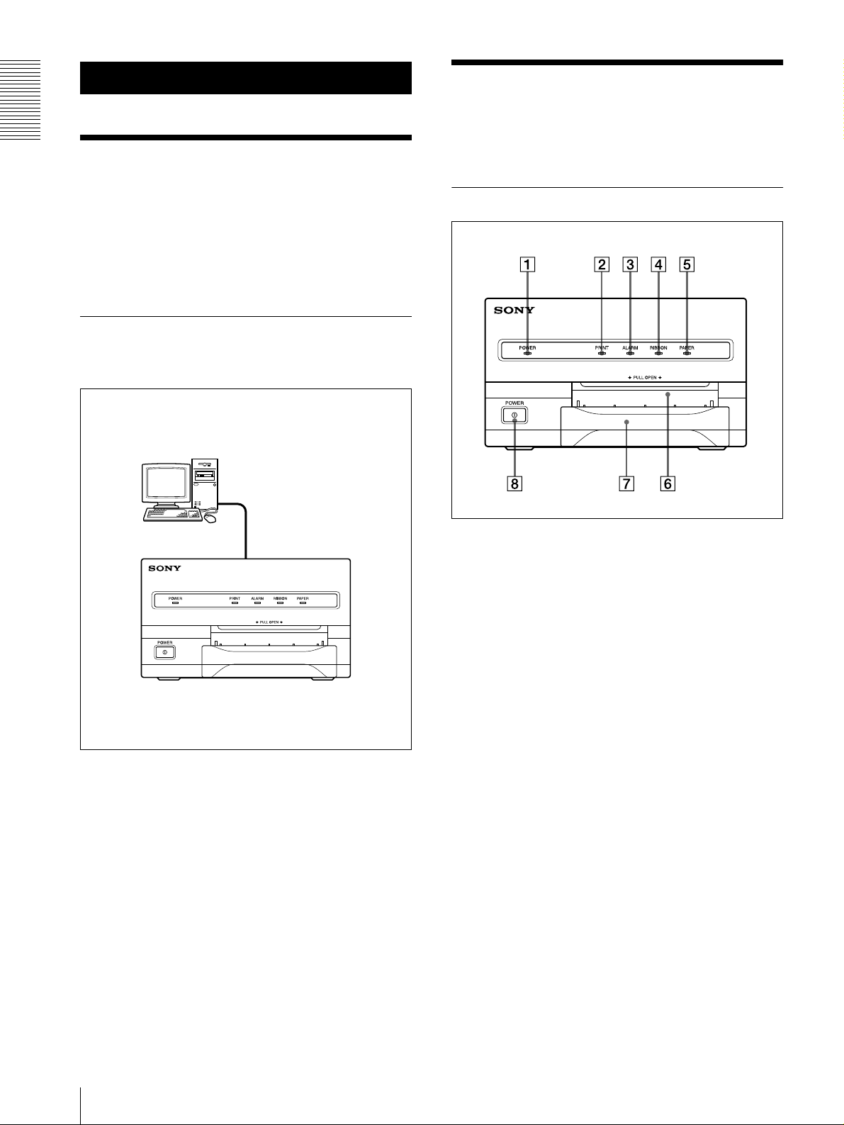
Front Panel
A POWER indicator
Ligh ts whe n the P O WER switc h of the printer is set
to ON.
Digital color printer
B PRINT indicator (15)
Lights while the printer is printing.
C ALARM indicator (15)
Lights in orange in case of paper jamm ing or
occurrence of any other problem.
D RIBBON in d icator (15 )
Lights when a problem for ink ribbon o ccurs.
E P APER indicator (15)
Lights when a problem for p aper oc curs.
The printer allows you to check the printer
operating condition according to the lighting
conditions of the PRINT indicator, ALARM
indicator, PAPER indicator and RIBB ON indicator .
For details, see “Indicators on the Front P ane l” on
page 15.
4
System Overview / Location and Function of Parts and Controls
F Paper output slot
Printed pages are ejected here.
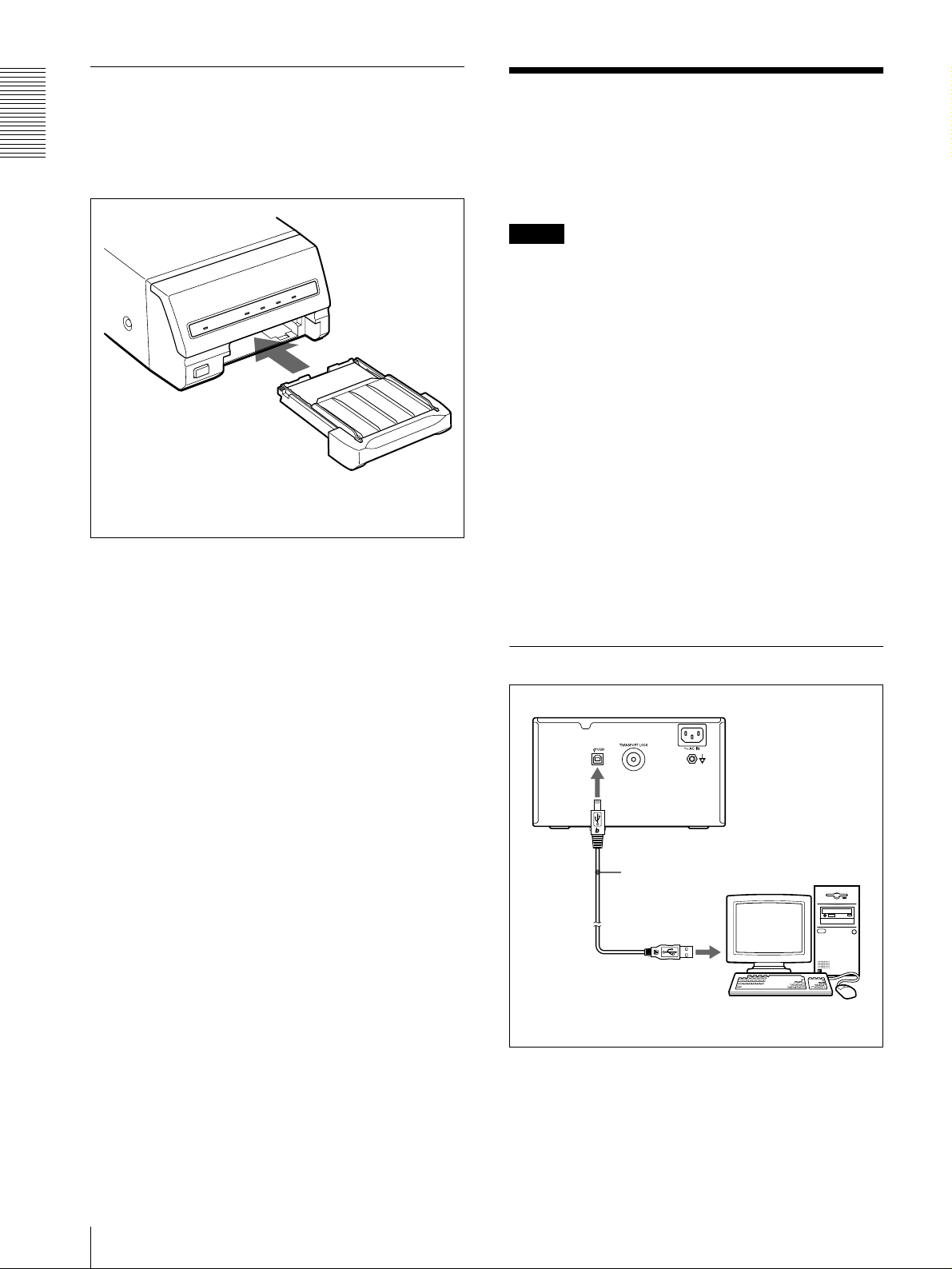
Supplied Accessories
G Paper tray (6)
Load p aper into this tray.
H ! POWER switch (11)
Press this switch to turn the printer on or off.
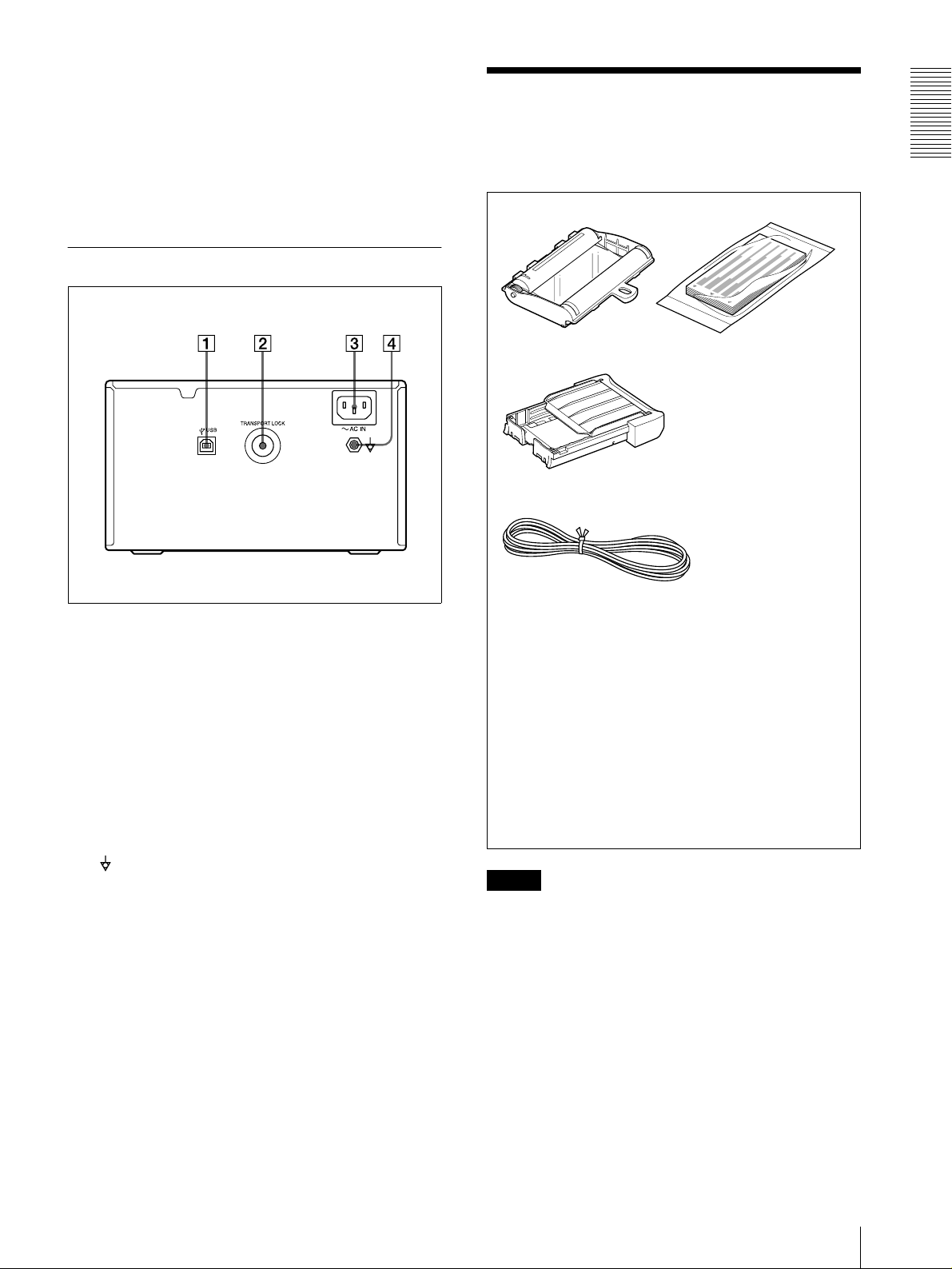
Rear Panel
The printer is packed together with the follo wing
accessories. Check that nothing is missing from y our
package.
Ink Ribbon and paper a) (1)
Paper Tray (1)
Power Cord (1)
Getting Started
A USB connector (6)
Connects to a computer or another U SB peripheral
device with a US B ca ble (supplied).
B TRANSPORT LOCK button (12)
Press this button to secure the internal thermal head
when transporting the printer .
C - AC IN conn ector
Used to connect the printer to a w all outlet with the
supplied power cord.
D Equipotential grou nd terminal connector
Used to connect to the equipotential plug to bring
the various parts of a system to the sa me potential.
Refer to “Imp ortant safe gu ards/notices for use in
the medical en vironments” on page 2.
USB connecting cable (1)
Warranty card (1) (for the customers in the
U.S.A and Canada only)
Software Licence Agreement (1)
CD-ROM (1)
Thermal head cleaning cartr i dge (1)
Before Using this Printer (1)
a) Use the ink ribbon cartridge and paper for an operation
check.
Notes
• Retain the original carton and packing materials in
case you hav e to transp ort the unit in the future.
• Remov e the ink ribbon cartridge an d paper tray w hen
transporting the printer.
• When transporting the printer, secure the thermal
head. (For detailed information on how to secure it,
see “Before Transporting the Printer” on page 12.)
Supplied Accessories
5
Assembly
Connections
To attach the pa p e r tray
For details of how to loa d the ink ribb on an d paper, see
Getting Started
“Loading an Ink Ribbo n” on page 8 and “Loading
Paper” on page 10.
Paper tray
After connecting the USB conn ecting cable (sup plied)
to the printer and the computer, connect the power cord.
For details about the printer connection, refer to the
manuals for the computer or o ther peripheral d evices.
Notes
• Before connecting the printer to the com puter, turn of f
the printer, computer, monitor, and all peripheral
devices connected to the computer.
• Before connecting the printer to the com puter,
disconnect the powe r cord from the printer. Connect
the power cord to the printer only after c onnecting the
printer and the computer.
• The printer is provided w ith a U S B interfa ce that can
be connected to any computer equipped with a USB
interface.
• Follow the conn ection proce dures d escribed in the
computer manual.
• Make sure that the interface cab le is connec ted
securely at both ends.
• The printer driv e software pro vided with the printer is
not suitable for using the printer connected to a
network.
• Operation of the printer is not guaranteed for
connection to a USB hub.
USB Port Connection
USB connecting
cable
6
Connections

Installing the Printer Driver
Install the printer driver provided w ith the p rinter. For
detailed instructions about how to install the printer
driver, refer to the Readme.txt file on the printer driv er
installer disc.
Getting Started
Installing the Printer Driver
7

• Do not touch the ink ribbon or place it in a dusty
Operation
location. Finger prints or dust on the ink ribbon will
result in imperfect printing or malfunction of the head.
• Use the ink ribbon and p aper supp lied with th e
printer for the initial operation check of the
printer.
Before Printing
Open the front panel by pulling the front panel
This section describes the operations below that m ust be
made before printing, but after mounting the paper tray
Operation
on the printer (see “Assembly” o n pag e 6) an d after
making the necessary connections (see “Connections”
on page 6).
• Loading an ink ribbon (See belo w.)
• Loading paper (See page 10.)
Once the abov e o perations have been completed, there
should be no need to repeat them during rou tine printing.
Perform them only as ne cessary.
Notes
• You can replace the ink ribbon or load pa per
regardless of whether the po wer is on or off. How ever ,
turning off the po we r w ill cause the imag e stored in
the memory to be lost.
• Use the ink ribbon and paper contained in the same
package as a pair. Before attempting to load an ink
ribbon or paper, mak e sure that the combination of the
ink ribbon and paper is compatible. Whe n either an
ink ribbon or paper has been exha usted, replace both
the ink ribbon and paper at the same time.
• Use only ink ribbon and paper designed for u se with
this printer. Failing to do so is likely to result in
malfunctions. (See“Ink Ribbo n and Paper” on page
13.)
1
toward you.
Note
Be sure not to open the front panel w hen printing.
Remov e the spent ink ribbon.
2
When you use the printer for the first time, this
operation is not required.
Loading an Ink Ribbon
Load an ink ribbon into the printer’s ink ribbon
compartment.
Notes
• When you use the printer for the first time, the
thermal head m ay be o ut of position. Before
attempting to use the in k ribbon, turn on the powe r
under the condition w here th e fron t panel is closed
so that the thermal head is place d at th e correct
position.
• When transporting the printer , rem ove the ink ribbon
and secure the thermal head.
• If a blank sheet of paper is ejected, and the RIB BON
indicator lights, the ink ribbon has been exhausted.
Replace the paper together w ith the ink ribbon. Do not
reuse the ejected blank paper.
• Once an ink ribbon has been c ompletely used up,
replace it. An ink ribbon is not reusable.
• Do not rew ind the ink ribbo n for reuse .
8
Before Printing

Remove an y slack from the ink ribbon.
3
Note
If the ribbon is left slack, it may be dam aged w hen
insert ed.
Wind the spools in the
direction of the arrow until the
start position marker appears
as illustrated
Load the new ink ribbon into the ink ribbo n
4
Start position marker
compartment.
while you are printing or cleaning the internal
thermal head.
Operation
Push the point marked
“PULL OPEN”
When storing ink ribbon cartridge:
• Avoid placing the ink ribbon in a location subject to:
– high temperatures
– high humidity
– excessive dust
– direct sunlight
• Store a partially used ink ribbon in its original
packaging.
Insert the hole of the
handle of the ink
ribbon over the
protruberance of the
printer
Close the front panel by pushing the point marked
5
with “PULL OPEN”.
If your ink ribb o n sh o u ld tea r
Repair the tear with transparent tape. There should be no
problem with using the remaining portion of the ribbon.
Transparent tape
Turn the spools in the direction of the arrow to
remove any slack until the transparent tape
cannot be seen.
Note
Be sure to close the front panel completely. If you
do not, a paper jam or a malfunction m a y occ ur
Before Printing
9

Loading Paper
To load paper, follow the proced ure be lo w. Be careful
not to touch the printing surface.
Notes
• Do not place dif ferent types of paper in the tray at
the same time.
• Use only paper recommended. Failing to do so is
likely to result in malfunctions such as paper jams.
(See “Ink Ribbon and P ap er” on page 13.)
Operation
• When a blank sheet of paper is ejected and the
RIBBON indicator lights, the ink ribbon has been
Riffle the paper with
the protection sheet.
Place the paper along
with the protection sheet
in the paper tray with the
printing surface facing up.
exhausted. Replace the paper together w ith the ink
ribbon. Do not use the ejected blank paper.
Remov e the paper tray .
1
Front
Set the paper with the
arrow on the protection
sheet pointing in the
same direction as the
arrow in the tray.
Partition
Place the paper in the paper tray so that the printing
2
Set the paper securely
under the tab.
surface faces up w ith the protection sheet o n top.
When the U P C -21L printing pack is used: Lay
the partition down.
When the UP C-21S printing pack is used: Raise
Remov e the protection shee t placed on the top o f
3
the paper.
the partition.
Slide the paper tray back into the printer until it
4
Notes
clicks into place.
10
• The paper tray holds up to 50 sheets of paper
when the UPC-21 L p rinting pack is used and 80
sheets of paper when the UP C-21S printing pack
is used.
• When handling the paper, do not touch the
printing surface. Dust or finger prints are likely to
cause unsatisfactory printing or malfunction of
the head. Grasp the paper by the printing su rface
protection sheet.
• When loading the paper, set the paper with the
arrow on the protection sheet pointing in the same
direction as the arrow in the paper tray . Also, load
the paper so that it lays flat in the paper tray. If the
paper is curled, it will overflow from the paper
tray and paper may not be fed properly . Be sure to
riffle the paper along with the protection sheets
before attempting to place the paper in the paper
tray.
Before Printing
When storing the paper
• Avoid storing the paper in a location subject to:
– high temperatures
– high humidity
– excessive dust
– direct sunlight
• Use the original package for storing unused pap er.

Printing
Before printing
• Ensure that the printer is properly connected to the
computer .
• Ensure that the ink ribbon and paper are p roperly
loaded.
• Ensure that the printer driv er has b een installed.
POWER indicator
PRINT indic a to r
ALARM indicator
RIBBON indicator
PAPER indicator
accumulated on the paper tray. The printer will start
automatically to print the remaining copies.
If the printer does not print
The printer will fail to print when the ALAR M, P A PER,
and/or RIBBON indicator light.
For details, see “Indicators on the Fron t Pane l” on pag e
15.
If the paper or ink ribbon runs out during
printing
The printer stops the printing operation.
Load the paper into the paper tray and the ink ribbon.
Printing of remaining copies is automatically started.
When storing y o ur printouts
• A void storing the p rintout in a location subject to high
temperatures, high humidity , e xcessive d ust and direct
sunlight.
• Do not stick tape on a printout. Also, avoid leaving a
plastic eraser on a printout or placing a printout in
contact with materials which contain plasticizer
(under a desk mat, for ex am ple).
Operation
1
Press the POWER switch to turn the printer on.
1
The POWER ind icator lig hts.
PRINT, ALARM, RIBBON and PAPER indicators
light at the same time, then all of them go out.
Notes
• Turn the printer on first.
• Do not turn the computer o f f and o n w hile it is
accessing a hard or floppy disk.
Turn on the power of the computer.
2
Execute the print job with software application.
3
While the printer is receiving the im ag e data from
the computer , the PR IN T indicator blinks.
While the printer is printing, the PRINT ind icator
lights.
Note
• Do not turn off the po wer during printing. If you do so,
paper may not be ejected and may jam in the printer.
• Do not pull the paper out till the printer finishes
printing.
• You c a n make multiple c o p i e s of identic al printouts.
However, the printer may stop printing for various
reasons. In such a case, remove the printouts
Printing
11

and may ev en de velop a fau lt if you persist in using it.
Miscellaneous
Precaution
Safety
• Operate the printer using the power source specif ied in
“Specifications” on page 14.
• Be careful not to damage the AC power cord by
placing or dropping heavy objects on it; it is dangerous
Miscellaneous
to use the unit with a damaged AC power cord.
• If you do not intend to use the unit for a long time,
disconnect the A C power cord.
• Unplug the AC power cord by grasp ing the p lug, not
the cable itself.
• Do not disassemble the unit.
• Do not remov e the cover. There is a danger of electric
shock from the internal parts.
• Be careful not to spill water or other liquids on the
unit, or to allow com bustible or metallic material to
enter the cabinet. If used with foreign matter in the
cabinet, the unit is liable to fail, or present a risk of fire
or electric shock.
• V e ntilation holes are provided to prev ent the unit from
overheating. Be careful no t to obstruct them with other
units or by cov e ring the unit w ith a cloth, etc.
• If the unit malfunctions or if a foreign body falls into
the cabinet, disconnect the AC power cord
immediately and consult y our Son y service f acility or
your Sony dealer.
Installation
• Avoid placing the unit in a location subject to:
– mechanical vibration
– high humidity
– excessive dust
– direct or excessive sunlight
– extremely high or low temperatures
• Do not use other electronic equipment ne ar the un it.
The unit will not work properly in strong
electromagnetic fields.
• Do not place a heavy ob ject such as a m onitor on the
printer.
If condensation forms, turn off the po wer and leave the
printer to stand for at least one hour .
• If the printing pack is subjected to wide or sudden
changes in temperature, condensation m ay form on
the ink ribbon or paper. This will cause the printer to
malfunction. Also, if the printing pack is used in this
state, spots are likely to appear on the printout.
Therefore, avoid storing the printing pack in locations
subject to wide or sudden changes of temperature.
• To store a half-used printing pack, replace it in its
original packing and reseal the package. If possible,
keep the sealed printing pack in a cool, dark loca tion.
To subsequently use the printing pack, place it, in its
sealed package, in a warm room for several hours.
Doing so prevents condensation from forming when
the printing pack is removed from its package.
Location
To prevent internal heat bu ilt-up, lea v e enou gh roo m
around the printer for air to circulate through the vents
on the left hand side and top of the cabinet.
Before Transporting the Printer
Before transporting the printer, use the following
procedure to remov e the supplied ac cessories and then
put them back into their original packing. Transporting
the printer with the supplied accessories still installed
may cause malfunctions.
Remov e the ink ribbon and the pape r tray.
1
Secure the internal thermal head, as follow s:
2
1 Turn on the printer.
2 Press the TRANSPORT LOCK button on the
rear panel of the printer.
The PRINT, ALARM, RIBBON and PAPER
indicators are blinking and the printer operation
tone keeps sounding for about tw o secon d s.
3 When the printer operation tone stops
sounding, turn off the power of the printer.
The thermal head is now secured.
T o releas e the therm al head
Turn on the printer again. The therm al head moves so
that you can now install the ink ribbon again.
Condensation
• If the printer is subject to wide or sudden changes in
temperature, such as when it is moved from a cold
room to a warm room or when it is left in a room with
a heater that tends to produce large amou nts of
moisture, condensation may form inside the printer. In
such cases the printer will probably not w ork properly ,
12
Precaution

Cleaning
Note
Be sure to turn off the power of the printer before
cleaning.
Ink Ribbon and Paper
Both paper and an ink ribbon are ne cessary for printing.
Use the ink ribbon with the paper contained in the same
package.
Cleaning the cabinet
Clean the cabinet, panel and controls with a soft dry
cloth, or a soft cloth lightly moistened with a mild
detergent solution. Do not use any type of solvent, such
as alcohol or benzine, which ma y damage the finish.
Cleaning the thermal head
Clean the thermal head w ith the therm al head cleaning
cartridge (supplied) if the printout quality deteriorates,
for example, when the w h ite stripes begin to appea r on
the printout.
It is recommended that you clean the thermal h ead after
every 10 p acks of paper to keep the printout quality at its
best.
Remove the pap er tray and remove the paper .
1
Place the cleaning sheet in the paper tray so that the
2
shiny surface faces do wn.
Notes
• Be sure to use the cleaning sheet supplied with
the U PC-21L /21S color printin g pack.
• Do not reuse the old cleaning sheet.
UPC-21S Color Printing Pack
Contains color ink ribbon cartridge and paper.
Color ink ribbon, 3 rolls
90 × 100 mm (5 3/4 × 8 3/8 inches) size paper, 1 package
(80 sheets) × 3
UPC-21L Color Printing Pack
Contains color ink ribbon cartridge and paper.
Color ink ribbon, 4 rolls
100 × 144 mm (5 3/4 × 8 3/8 inches) size paper, 1
package (50 sheets) × 4
Note
If the paper has been exhausted, replace the ink ribbon
toget h e r with the p aper.
Miscellaneous
Load the cleaning cartridge into the ribbon
3
compartment.
Immediately after you load the paper tray with the
cleaning sheet and cleaning cartridge, the RIBBON
indicator goes off and the p rinter starts cleaning the
thermal head automati cally.
When the printer has com pleted cleaning the
thermal head, the RIBBON indicator goes on again.
Note
When you load the clean ing cartridge into the ink
ribbon compartment with the printer’s power on,
the printer starts cleaning.
If the printer is not turned on, even thou gh you turn
on the power after loading the cleaning cartridge,
the printer will not start cleaning.
Ink Ribbon and Paper
13

Protection against harmful ingress of
Specifications
Power requirements
100 to 120 V AC only , 50/60 H z
(for 100 to 120 V AC users)
220 to 240 V AC only , 50/60 H z
(for 220 to 240 V AC users)
Power consumption
water:
Ordinary
Degree of safety in the presenc e of
flammable anesthetics or oxygen:
Not suitable for use in the presence
of flammable anesthetics or oxygen
Mode of operation:
Continuous
About 1.8 A max. at 25°C
(for 100 to 120 V AC users)
About 1.0 A max . at 25°C
(for 220 to 240 V AC users)
Operating temperature
USB Interface
Data transmission
Univ ersal Serial Bus Specification
Rev.1.1 Standard
5°C to 35°C (41°F to 95°F)
Miscellaneous
Operating humidity
USB Interface Connector Pin Assignment
20% to 80% (no condensation allo wed)
Storage and transport temperature
–20°C to 60°C (–4°F to 140°F)
Storage and transport humidity
20% to 90% (no condensation allo wed)
Dimensions About 212 × 125 × 395 mm (w/h/d)
(8 3/8 × 5 × 15 5/8 inches)
Mass A bout 6.5 kg (14 lb 5 oz)
Printing system Sublimation heat transfer printing
I/O Signal Function
VCC Cable power, Max. current 100
mA
I/O –Data Data
I/O +Data Data, pull up to +3.3V through a
1.5kΩ resistance
Ground Cable ground
Printable pixels When using the UPC -21S and printing
the full-image: 1520 × 11 44 d ots
When using the UPC -21L and printing
the full-image: 2000 × 15 20 d ots
Design and specifications are subject to ch ange w ithout
notice.
Total gradation 256 lev els each fo r yellow, magenta,
and cyan
Printing time When using the UPC-21S:
When the printer is set to high
speed: Approximately 19 seconds
When using the UPC-21L:
When the printer is set to high
speed: Approximately 29 seconds
Thermal head 15.87 dots/mm
Input connector A C IN (for power input)
Supplied accessories
Color printing pack (1)
Paper tray (1)
USB connecting cable (1)
Thermal head cleaning cartridge (1)
A C p ower cord (1)
W arranty card (1) (for the customers in
the U.S.A. and Canada only)
Software License A g reement (1)
Before Using this Printer (1)
CD-ROM (1)
Optional accessories
UPC-21L C olor P rinting Pack
UPC-21S Color Printing Pack
Medical Specifications
Protection against electric shock:
Class I
14
Spe cifications

Troubleshooting
Indicators on the Front
The following troubleshooting che cks will help you
correct the most common problem s you m ay encounter
with your unit. Before proceeding w ith these trouble
checks, first check that the power cord is firmly
connected. Should the problem p ersist after you ha ve
applied the remedy, unplug the unit and contact your
Sony dealer or local authorized So n y service f acility.
Symptoms Possible causes and remedies
The printer does not
print, even if the
command is sent
from the computer.
The printer does not
print.
The printout color is
very pale.
The ink ribbon cannot
be loaded.
The blank paper is
ejected and the
RIBBON indicator
lights.
• The POWER switch of the printer is
not set to ON.
tSet the POWER switch of the
printer to ON.
• Connections may not be correct.
tCheck connections and rectify, if
necessary. (See page 6.)
The problem is in dicated by the
indicators on the front panel.
tSee “Indicators on the Front Panel”
on page 15.)
The paper is not loaded correctly.
tCheck which side of the paper is the
printing side, then load the paper
again. (See page 10.)
• You may be trying to load an ink
ribbon that can not be used with this
printer has been l oaded.
tLoad the appropriate ink ribbon.
(See page 13.)
• The thermal is secured.
tTurn on the printer. Th e therm a l
head moves so that you can now
install the ink ribbon. (See
page 12.)
The ink ribbon has been exhausted. Do
not reuse the ejected blank paper.
tReplace the ink ribbon. (See pages 8
and 10.)
Panel
If a problem occurs, the indicators on the front panel
such as PRINT , ALAR M, RIBBON and/or P APER light
or blink to indicate the problem condition. the following
table shows the relation between lighting or b linking
condition of each indicator and possible cause and
remedies.
Indicators Possible cause and
Lighting Blinking
PRINT Printing
PRINT Data receiving
PRINT
RIBBON • The ink ribbon has been
PAPER • Paper has been exhausted.
ALARM and
PAPER
ALARM and
RIBBON
remedies
a)
The thermal head is being
heated so that the printer is
ready to start.
exhausted.
tRepl ace the old one with
a new ink ribbon. (See
page 8.) (The ink ribbon
cannot be reused.) In this
case, if the white paper is
ejected. Discard this
paper.
• The ink ribbon has torn.
tRepair the torn ink
ribbon. (See page 9.)
tLoad the paper. (See
page 10.) Also, replace
the ink ribbon.
• The paper tray is not
installed.
tInstall the paper tray.
(See page 6)
The ink ribbon and paper are
not compatible.
tUse the ink ribbon and paper
contained in the s ame
package. (See page 13.)
The wrong ink ribbon and the
paper are loaded when
replacing them bec a use the ink
ribbon and/or pa per run out
during printin g.
tLoad the same ink ribbon
and paper as ones used
before replacing with new
ones.
Miscellaneous
Troubleshooting / Indicators on the Front Panel
15

Indicators Possible cause and
Lighting Blinking
ALARM • The front panel is open.
remedies
tC lose the front door
surely.
• Paper has jammed inside the
printer.
tRemove any jammed
paper from the printer.
(See page 16.)
• The maximu m number of
printouts has ac cu m ula t e d
on the paper tray.
tRemove the printouts.
Printing starts again.
If the Paper Jams
If the paper jams after you press the PRINT button,
remove the jammed paper following the steps below.
Remov e the pape r tray.
1
If any printouts have been ejected onto the paper
tray and have ac cumulated on the paper tray,
remove them before removing the paper tray.
Miscellaneous
a) The indicator blinks slowly.
Check whether any paper is jammed inside the
2
printer. If you find a jammed sheet, slowly pull it
straight out.
16
If the Paper Jams
Load the paper into the paper tray correctly.
3
Set the paper
securely
under the
tabs.

Notes
• Do not reuse the jamm ed pa per. Discard that
paper.
• Use only paper recom me nded in this m a nual.
Re-insert the removed pape r tray.
4
Miscellaneous
If the Pap e r J a m s
17

S
Index
A
Accessories
assembly 6
ink ribbon and paper 5
paper tray 5
power cord 5
thermal head cleaning cartridge 5
USB connecting cable 5
Alarm
indicating the problem using the
indicators 15
Specification 14
System configuration 4
System overview 4
T
Thermal head
cleaning 13
releasing 12
securing 12
Troubleshooting 15
U
USB interface 14
USB port connection 6
C
Cleaning
cabinet 13
Index
thermal head 13
Connections 6
G
Getting Started 4
I
Ink ribbon
loading 8
notes on storing 9
L
Location a nd function of parts and
controls
front panel 4
O
Operation 8
P
Paper
loading 10
notes on storing 10
Paper jams 16
Precaution
before transporting the printer 12
condensation 12
installation 12
safety 12
Printer driver
installing 7
Printing 11
Printing pack
available printing pack 13
18
Index

Sony Corporation
 Loading...