


4-488-657-11 (1)
Hybrid Graphic Printer
Instructions for Use
Before operating the unit, please read this manual thoroughly
and retain it for future reference.
UP-991AD/UP-971AD
© 2014 Sony Corporation
Indication for Use / Intended use
The Sony UP-971AD and UP-991AD are compact,
medical grade black and white printers that can accept
both analog and digital signal inputs. They are designed
to be integrated into radiology imaging systems such as
mobile c-arm, ultrasound, cardiac cath lab and other
compatible medical imaging systems and produce hard
copy prints of still images captured by these systems for
the patient record or for referrals.
Symbols on the products
General warning sign
Follow the warnings in the Instructions for
Use for parts of the unit on which this mark
appears.
NOTE Background color: Yellow
Triangular band: Black
Symbol: Black
Note
Images printed from the unit cannot be used for
diagnostic use.
Caution
Federal law (United States of America) restricts this
device to sale by or on the order of a licensed healthcare
practitioner.
Owner’s Record
The model and serial numbers are located at the rear.
Record these numbers in the space provided below.
Refer to these numbers whenever you call upon your
Sony dealer regarding this product.
Model No. ____________________
Serial No. ____________________
WARNING
To reduce the risk of fire or electric shock, do
not expose this apparatus to rain or moisture.
To avoid electrical shock, do not open the
cabinet. Refer servicing to qualified personnel
only.
No modification of this equipment is allowed.
THIS APPARATUS MUST BE EARTHED.
To disconnect the main power, unplug the
power plug.
When installing the unit, incorporate a readily
accessible disconnect device in the fixed
wiring, or connect the power plug to an easily
accessible socket-outlet near the unit.
Do not position the ME equipment where it is
difficult to unplug the power plug.
If a fault should occur during operation of the
unit, operate the disconnect device to
switch the power supply off, or unplug the
power plug.
Consult the Instructions for Use
Follow the directions in the Instructions for
Use for parts of the unit on which this mark
appears.
This symbol indicates the manufacturer, and
appears next to the manufacturer’s name and
address.
This symbol indicates the European
Community representative, and appears next
to the European Community representative’s
name and address.
This symbol indicates the equipotential
terminal which brings the various parts of a
system to the same potential.
For the customers in the U.S.A.
This equipment has been tested and found to comply
with the limits for a Class A digital device, pursuant to
part 15 of the FCC Rules. These limits are designed to
provide reasonable protection against harmful
interference when the equipment is operated in a
commercial environment. This equipment generates,
uses and can radiate radio frequency energy and, if not
installed and used in accordance with the instruction
manual, may cause harmful interference to radio
communications. Operation of this equipment in a
residential area is likely to cause harmful interference in
which case the user will be required to correct the
interference at his own expense.
You are cautioned that any changes or modifications not
expressly approved in this manual could void your
authority to operate this equipment.
All interface cables used to connect peripherals must be
shielded in order to comply with the limits for a digital
device pursuant to Subpart B of part 15 of FCC Rules.
2

This device complies with part 15 of the FCC Rules.
Operation is subject to the following two conditions:
(1) This device may not cause harmful interference, and
(2) this device must accept any interference received,
including interference that may cause undesired
operation.
For the customers in Canada
CAN ICES-3 (A)/NMB-3(A)
This unit has been certified according to Standard
CAN/CSA-C22.2 No.60601-1.
Important safeguards/notices for use in
the medical environments
1. All the equipments connected to this unit shall be
certified according to Standard IEC60601-1,
IEC60950-1, IEC60065 or other IEC/ISO Standards
applicable to the equipments.
2. Furthermore all configurations shall comply with the
system standard IEC 60601-1-1. Everybody who
connects additional equipment to the signal input
part or signal output part configures a medical
system, and is therefore, responsible that the system
complies with the requirements of the system
standard IEC60601-1-1. If in doubt, consult the
qualified service personnel.
3. The leakage current could increase when connected
to other equipment.
4. For this particular equipment, all accessory
equipment connected as noted above, must be
connected to mains via an additional isolation
transformer conforming with the construction
requirements of IEC60601-1 and providing at least
Basic Insulation.
5. This equipment generates, uses, and can radiate radio
frequency energy. If it is not installed and used in
accordance with the instruction manual, it may cause
interference to other equipment. If this unit causes
interference (which can be determined by
unplugging the power cord from the unit), try these
measures: Relocate the unit with respect to the
susceptible equipment. Plug this unit and the
susceptible equipment into different branch circuit.
Consult your dealer. (According to standard IEC606011-2 and CISPR11, Class B, Group 1)
3
Important EMC notices for use in the medical environments
• The UP-991AD/UP-971AD needs special precautions
regarding EMC and needs to be installed and put into
service according to the EMC information provided in this
instructions for use.
• The portable and mobile RF communications equipment
such as cellular phones can affect the UP-991AD/UP971AD.
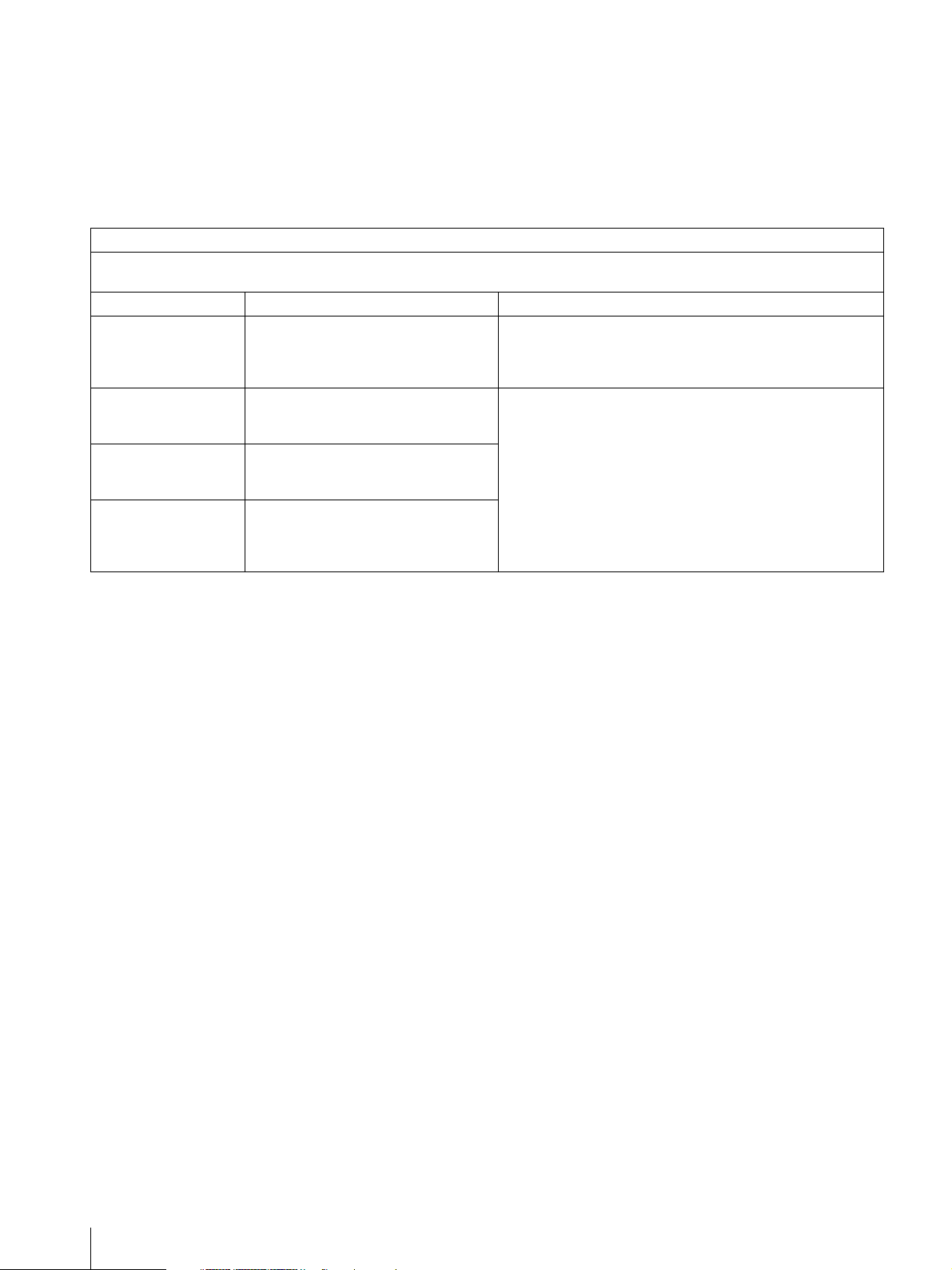
Guidance and manufacturer’s declaration-electromagnetic emissions
The UP-991AD/UP-971AD is intended for use in the electromagnetic environment specified below.
The customer or the user of the UP-991AD/UP-971AD should assure that it is used in such an environment.
Emission test Compliance Electromagnetic environment-guidance
RF emissions
CISPR 11
RF emissions
CISPR 11
Harmonic emissions
IEC 61000-3-2
Voltage fluctuations/
flicker emissions
IEC 61000-3-3
Warning
If the UP-991AD/UP-971AD should be used adjacent to or
stacked with other equipment, it should be observed to
Group 1
Class B
Class A
Complies
Warning
The use of accessories and cables other than those
specified, with the exception of replacement parts sold by
Sony Corporation, may result in increased emissions or
decreased immunity of the UP-991AD/UP-971AD.
The UP-991AD/UP-971AD uses RF energy only for its
internal function. Therefore, its RF emissions are very low
and are not likely to cause any interference in nearby
electronic equipment.
The UP-991AD/UP-971AD is suitable for use in all
establishments, including domestic establishments and
those directly connected to the public low-voltage power
supply network that supplies buildings used for domestic
purposes.
verify normal operation in the configuration in which it will be
used.
4
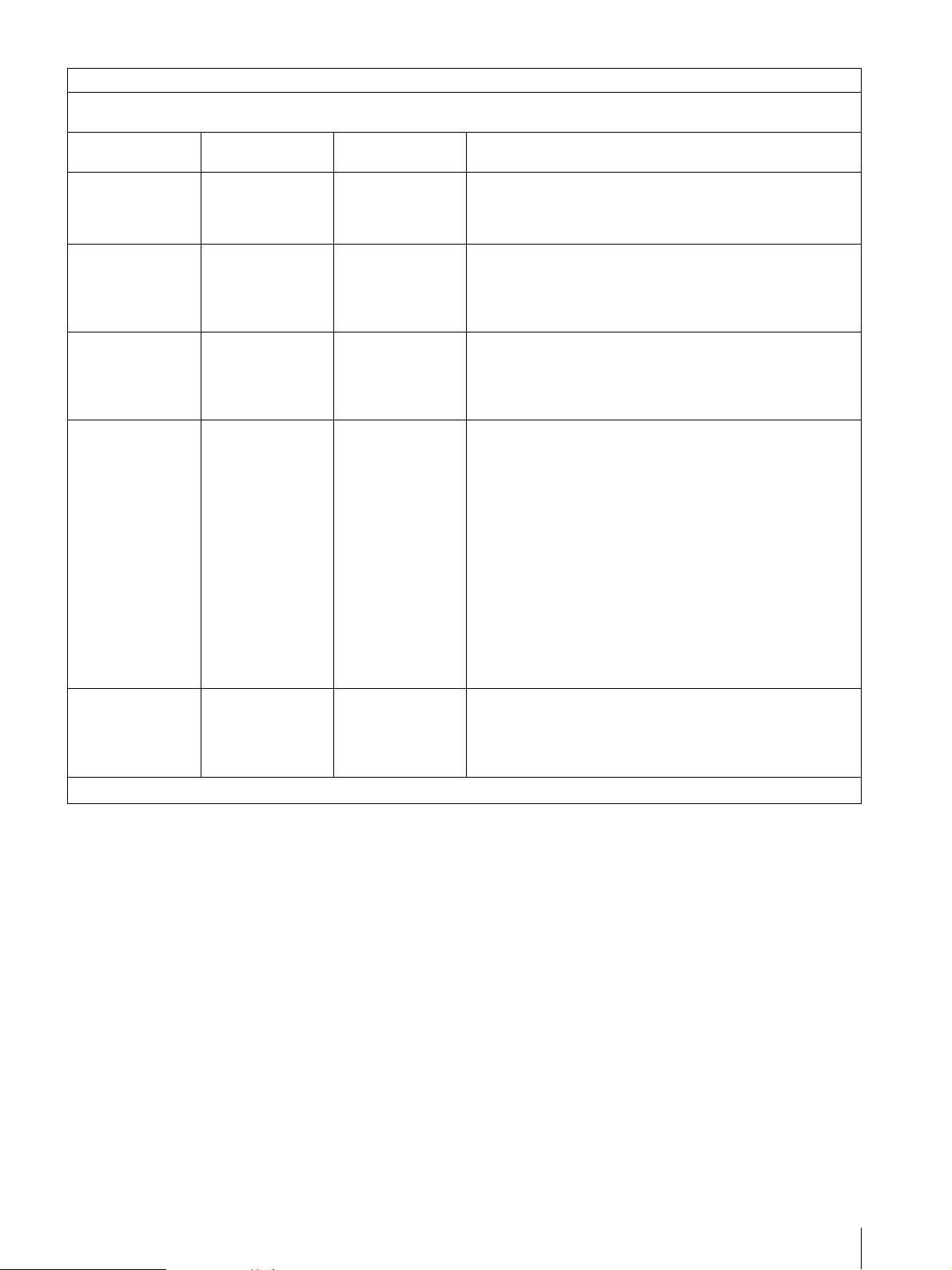
Guidance and manufacturer’s declaration - electromagnetic immunity
The UP-991AD/UP-971AD is intended for use in the electromagnetic environment specified below. The customer or the user
of the UP-991AD/UP-971AD should assure that it is used in such as environment.
Immunity test
Electrostatic
discharge (ESD)
IEC 60601 test
level
±6 kV contact
±8 kV air
Compliance level Electromagnetic environment-guidance
±6 kV contact
Floors should be wood, concrete or ceramic tile. If floors are
covered with synthetic material, the relative humidity should
±8 kV air
be at least 30 %.
IEC 61000-4-2
Electrical fast
transient/burst
±2 kV for power
supply lines
±2 kV for power
supply lines
Mains power quality should be that of a typical commercial or
hospital environment.
IEC 61000-4-4
Surge
IEC 61000-4-5
Voltage dips, short
interruptions and
voltage variations
on power supply
input lines
IEC 61000-4-11
Power frequency
(50/60Hz)
magnetic field
IEC 61000-4-8
NOTE: U
is the a.c. mains voltage prior to application of the test level.
T
±1 kV for input/
output lines
±1 kV differential
mode
±2 kV common
mode
< 5% U
T
(> 95% dip in U
for 0.5 cycle
40% UT
(60% dip in U
for 5 cycles
70% UT
(30% dip in U
for 25 cycles
< 5% U
T
(> 95% dip in U
for 5 sec
±1 kV for input/
output lines
±1 kV differential
mode
±2 kV common
mode
< 5% UT
(> 95% dip in U
)
T
for 0.5 cycle
40% UT
(60% dip in U
)
T
for 5 cycles
70% UT
(30% dip in U
)
T
for 25 cycles
< 5% U
(> 95% dip in U
)
T
for 5 sec
Mains power quality should be that of a typical commercial or
hospital environment.
Mains power quality should be that of a typical commercial or
hospital environment. If the user of the UP-991AD/UP-
)
T
971AD requires continued operation during power mains
interruptions, it is recommended that the UP-991AD/UP971AD be powered from an uninterruptible power supply or a
battery.
)
T
)
T
T
)
T
3 A/m 3 A/m Power frequency magnetic fields should be at least
characteristic of a typical location in a typical commercial or
hospital environment.
5
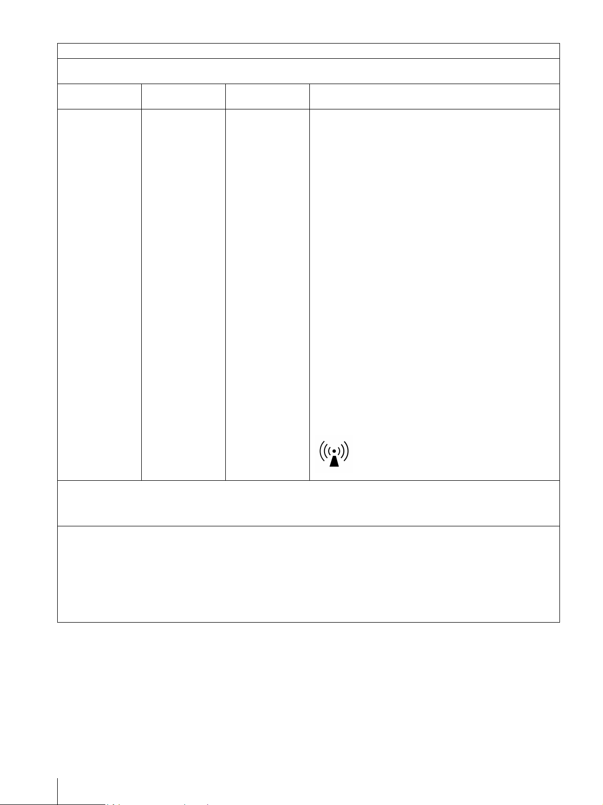
Guidance and manufacturer’s declaration - electromagnetic immunity
The UP-991AD/UP-971AD is intended for use in the electromagnetic environment specified below. The customer or the user
of the UP-991AD/UP-971AD should assure that it is used in such as environment.
Immunity test
IEC 60601 test
level
Compliance level Electromagnetic environment-guidance
Portable and mobile RF communications equipment should
be used no closer to any part of the UP-991AD/UP-971AD,
including cables, than the recommended separation distance
calculated from the equation appliance to the frequency of
the transmitter.
Recommended separation distance
Conducted RF
IEC 61000-4-6
Radiated RF
IEC 61000-4-3
NOTE 1: At 80 MHz and 800 MHz, the higher frequency range applies.
3 Vrms
150 kHz to 80 MHz
3 V/m
80 MHz to 2.5 GHz
3 Vrms
3 V/m
d = 1.2 √P
d = 1.2 √P 80 MHz to 800 MHz
d = 2.3 √P 800 MHz to 2.5 GHz
Where P is the maximum output power rating of the
transmitter in watts (W) according to the transmitter
manufacturer and d is the recommended separation distance
in meters (m).
Field strengths from fixed RF transmitters, as determined by
an electromagnetic site survey,
compliance level in each frequency range.
Interference may occur in the vicinity of equipment marked
with following symbol:
a
should be less than the
b
NOTE 2: These guidelines may not apply in all situations. Electromagnetic propagation is affected by absorption and
a Field strengths from fixed transmitters, such as base stations for radio (cellular/cordless) telephones and land mobile
radios, amateur radio, AM and FM radio broadcast and TV broadcast cannot be predicted theoretically with accuracy. To
assess the electromagnetic environment due to fixed RF transmitters, an electromagnetic site survey should be
considered. If the measured field strength in the location in which the UP-991AD/UP-971AD is used exceeds the
applicable RF compliance level above, the UP-991AD/UP-971AD should be observed to verify normal operation. If
abnormal performance is observed, additional measures may be necessary, such as reorienting or relocating the
UP-991AD/UP-971AD.
b Over the frequency range 150 kHz to 80 MHz, field strengths should be less than 3 V/m.
reflection from structures, objects and people.
6
Recommended separation distances between portable and mobile RF communications equipment and the
UP-991AD/UP-971AD
The UP-991AD/UP-971AD is intended for use in an electromagnetic environment in which radiated RF disturbances are
controlled. The customer or the user of the UP-991AD/UP-971AD can help prevent electromagnetic interference by
maintaining a minimum distance between portable and mobile RF communications equipment (Transmitters) and the
UP-991AD/UP-971AD as recommended below, according to the maximum output power of the communications equipment.
Rated maximum output power of transmitter
W
0.01 0.12 0.12 0.23
0.1 0.38 0.38 0.73
1 1.2 1.2 2.3
10 3.8 3.8 7.3
100 12 12 23
For transmitters rated a maximum output power not listed above, the recommended separation distance d in meters (m) can
be estimated using the equation applicable to the frequency of the transmitter, where P is the maximum output power rating
of the transmitter in watts (W) according to the transmitter manufacturer.
NOTE 1: At 80 MHz and 800 MHz, the separation distance for the higher frequency range applies.
Separation distance according to frequency of transmitter
150 kHz to 80 MHz
d = 1.2 √P
80 MHz to 800 MHz
m
800 MHz to 2.5 GHz
d = 1.2 √P
d = 2.3 √P
NOTE 2: These guidelines may not apply in all situations. Electromagnetic propagation is affected by absorption and
reflection from structures, objects and people.
Caution
When you dispose of the unit or accessories, you must
obey the laws in the relative area or country and the
regulations in the relative hospital.
Warning on power connection for
medical use
Please use the following power supply cord.
With connectors (plug or female) and cord types other
Warning on power connection
Use a proper power cord for your local power supply.
1. Use the approved Power Cord (3-core mains lead) /
Appliance Connector / Plug with earthing-contacts
that conforms to the safety regulations of each
country if applicable.
2. Use the Power Cord (3-core mains lead) / Appliance
Connector /Plug conforming to the proper ratings
(Voltage, Ampere).
If you have questions on the use of the above Power
Cord/Appliance Connector/Plug, please consult a
than those indicated in this table, use the power supply
cord that is approved for use in your area.
United States and Canada
Plug Type HOSPITAL GRADE*
Cord Type Min.Type SJT
Minimum Rating for Plug
and Appliance Couplers
Safety Approval UL Listed and CSA
*Note: Grounding reliability can only be achieved when the equipment is connected to an equivalent receptacle marked ‘Hospital Only’
or ‘Hospital Grade’.
Min.18 AWG
10A/125V
qualified service personnel.
For the customers in Europe
This product has been manufactured by or on behalf of
Sony Corporation, 1-7-1 Konan Minato-ku Tokyo, 1080075 Japan. Inquiries related to product compliance
based on European Union legislation shall be addressed
to the authorized representative, Sony Deutschland
GmbH, Hedelfinger Strasse 61, 70327 Stuttgart,
Germany.
For any service or guarantee matters, please refer to the
addresses provided in the separate service or guarantee
documents.
7
For the State of California, USA only
Perchlorate Material – special handling may apply, See
www.dtsc.ca.gov/hazardouswaste/perchlorate
Perchlorate Material: Lithium battery contains
perchlorate
For the customers in the U.S.A.
SONY LIMITED WARRANTY - Please visit http://
www.sony.com/psa/warranty for important
information and complete terms and conditions of
Sony’s limited warranty applicable to this product.
For the customers in Taiwan only
Disposal of Old Electrical & Electronic
Equipment (Applicable in Republic of India)
This symbol indicates that this product shall not be
treated as household waste and may not be dropped in
garbage bins. Product owners are advised to deposit
their product at the nearest collection point for the
recycling of electrical and electronic equipment.
Your co-operation shall facilitate proper disposal & help
prevent potential negative consequences/hazards to the
environment and human health, which could otherwise
be caused by inappropriate waste disposal including
improper handling, accidental breakage, damage
and/ or improper recycling of e-waste. The recycling
of materials will help to conserve natural resources.
For the customers in Canada
SONY LIMITED WARRANTY - Please visit http://
www.sonybiz.ca/solutions/Support.do for important
information and complete terms and conditions of
Sony’s limited warranty applicable to this product.
For the customers in Europe
Sony Professional Solutions Europe - Standard
Warranty and Exceptions on Standard Warranty.
Please visit http://www.pro.sony.eu/warranty
important information and complete terms and
conditions.
for
For the customers in Korea
SONY LIMITED WARRANTY - Please visit http://
bpeng.sony.co.kr/handler/BPAS-Start for important
information and complete terms and conditions of
Sony’s limited warranty applicable to this product.
For more detailed information about recycling of this
product, please contact your local civic office, your
household waste disposal service provider or the store
where you made the purchase. You may contact our
company’s toll free number in India for assistance.
This product complies with the “India E-waste Rule
2011”. The Ewaste Rules, 2011 is an Indian directive
aimed at reducing the harmful environmental impact of
waste electrical equipment by restricting the use of
known hazardous substances. As of 1st May 2012, new
electrical and electronic equipment introduced into the
market may no longer contain the following chemicals
or its specified maximum concentration levels: Lead,
Mercury, Hexavalent Chromium, Polybrominated
Biphenyls (PBB) or Polybrominated Diphenylethers
(PBDE) - in concentrations exceeding 0.1 weight % and
Cadmium - 0.01 weight %, except of exemptions set in
Schedule 2 of the aforesaid Rule.
8

Table of Contents
Getting Started
Overview ............................................................... 10
Location and Function of Parts and
Controls ................................................................11
UP-991AD ........................................................ 11
UP-971AD ........................................................ 13
Preparation
Loading Paper in the Unit .................................. 15
Connections
Connecting to video devices ................................ 17
Connecting to a computer ................................... 18
Connecting to the USB Connector ................... 18
Operation
Adjustments and Settings Using the Menu ....... 19
Menu structure and layer .................................. 20
Menu List ......................................................... 21
Basic Menu Operations .................................... 25
Registering Menu Settings ...............................26
Printing the Menu List ...................................... 27
Printing ................................................................. 28
Starting a Print Job of Video Images ................ 28
Printing digital images from a computer .......... 31
Adjusting print image quality ........................... 32
Storing Image Data on a USB Flash Drive (UP-
991AD only) .......................................................... 34
Storing Image Data on a USB Flash Drive ...... 34
Others
Precautions ...........................................................36
On Safety ..........................................................36
On the Printer Carriage .....................................36
On Installation ...................................................36
About the battery (UP-991AD only) ................36
Maintenance .........................................................37
Cleaning the Cabinet .........................................37
Cleaning the Thermal Head ..............................37
Cleaning the Platen Roller ................................38
Paper .....................................................................38
Paper You Can Use ...........................................38
Specifications ........................................................39
UP-991AD ........................................................39
UP-971AD ........................................................40
License ...................................................................42
Troubleshooting ....................................................43
Error Messages .....................................................44
Index ......................................................................45
9
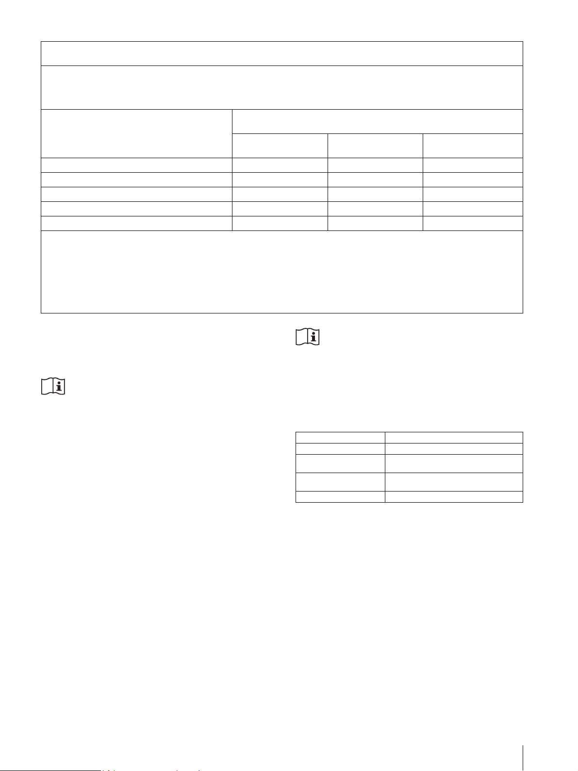
Easy picture quality adjustment function
Getting Started
By printing nine images as one page of which the
parameter is changed in picture quality adjustment
menu, you can select the most suitable adjustment.
Getting Started
Overview
Stable, high-quality printing
• Capable of high-resolution images of 12.8 dots/mm.
• 8-bit processing provides monochrome printing with
up to 256 shades of gradation.
BRIGHT=-12 BRIGHT=-8BRIGHT=-16
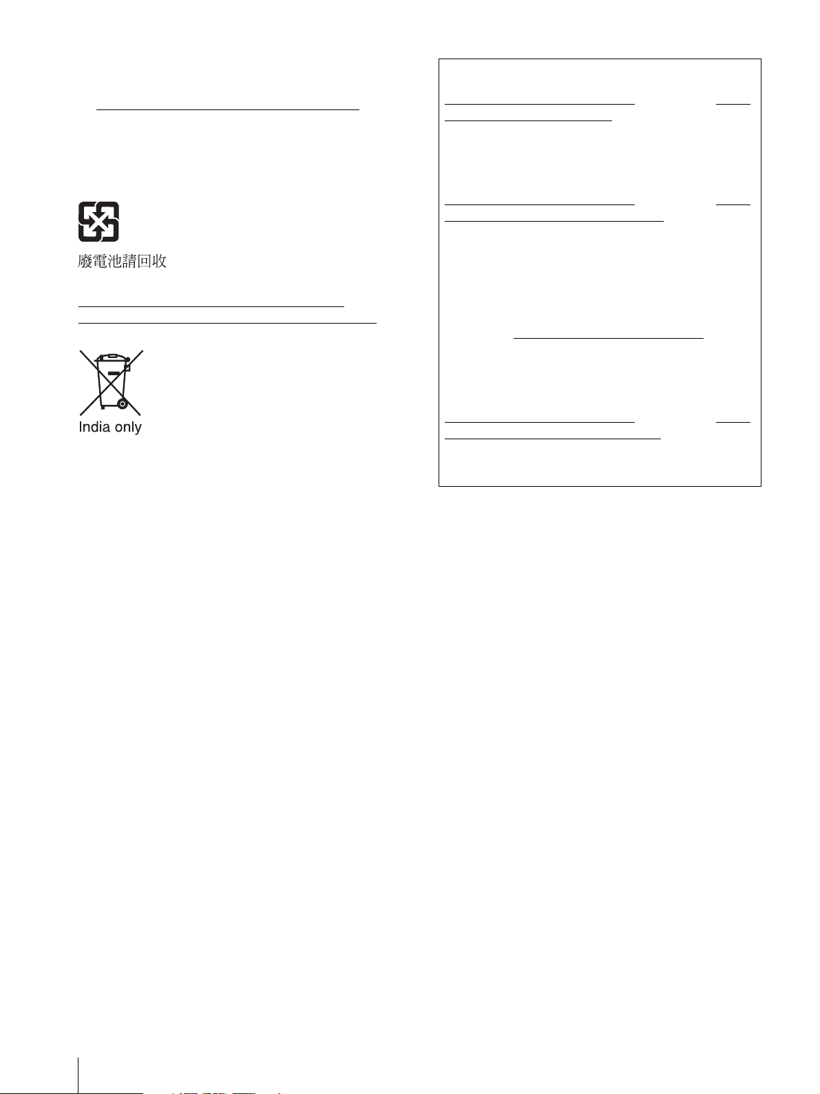
A variety of printing modes
Single-picture mode
Side mode
Reverse mode
Multi-picture mode
A change of settings makes available an even greater
number of print modes (see page 28).
Supports both video and digital input
• Prints captured images from color or monochrome
video signals in NTSC or PAL format.
• Prints the image from a computer which is compatible
with Hi-Speed USB (USB 2.0 compatible).
BRIGHT=0
BRIGHT=12 BRIGHT=16BRIGHT=8
CONTRAST=10 GAMMA=1 SHARP=2 TONE=8
BRIGHT=4BRIGHT=-4
Setting menu history function
Saves the last five menus that were used, allowing for
easy access to them next time.
Long-length picture printing
Supports 600 mm length digital printing.
Picture data to USB Flash Drive save function
(UP-991AD only)
Saves picture print data of both video and digital mode
to USB Flash Drive simultaneously when printing.
Auto cut function (UP-991AD only)
Automatically cuts the paper when printing completes.
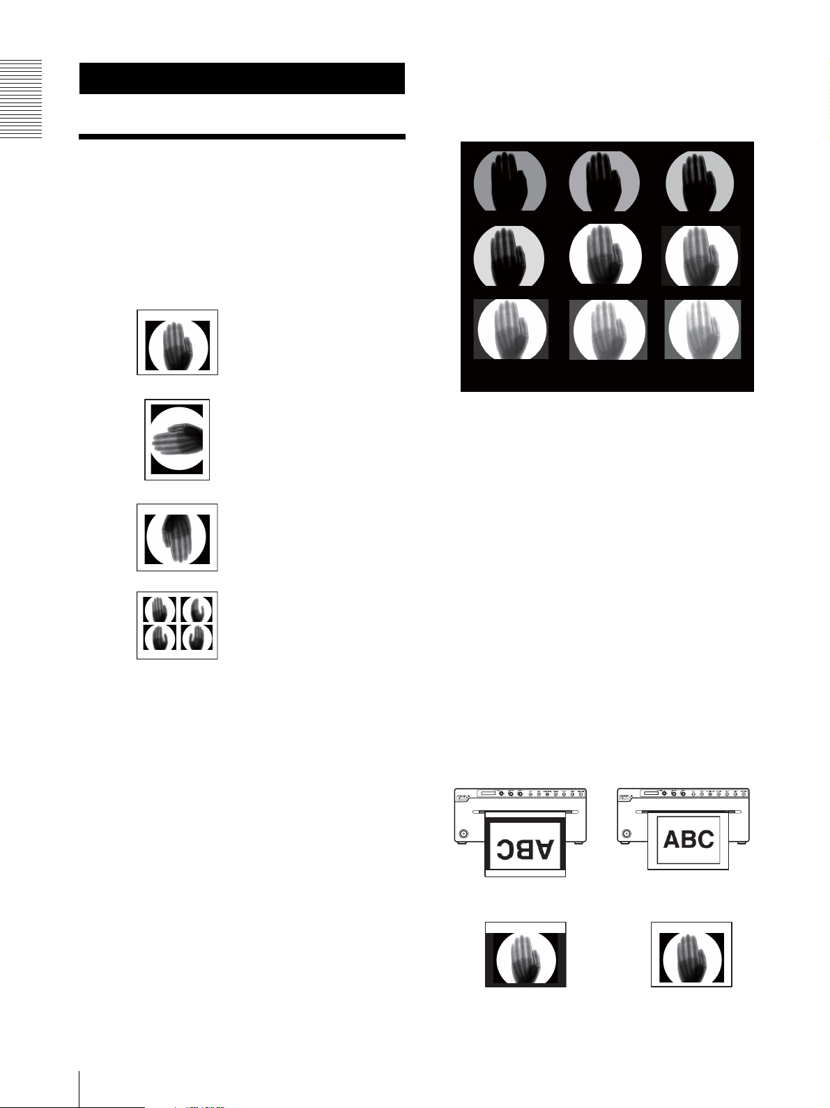
Printing to film (UP-991AD only)
The UP-991AD can print on transparent film using UPT210BL (separately sold).
The difference between film printing and paper printing
In film printing, images are printed from the top.
Film print (UPT-210BL) Paper print (UPP-210HD,
UPP-210SE)
10
Film printing has a function to print a margin in black.
Overview
Backlight of the buttons
The unit can be operated in low light conditions. Buttons
that are functional for a particular setting will become
lit.
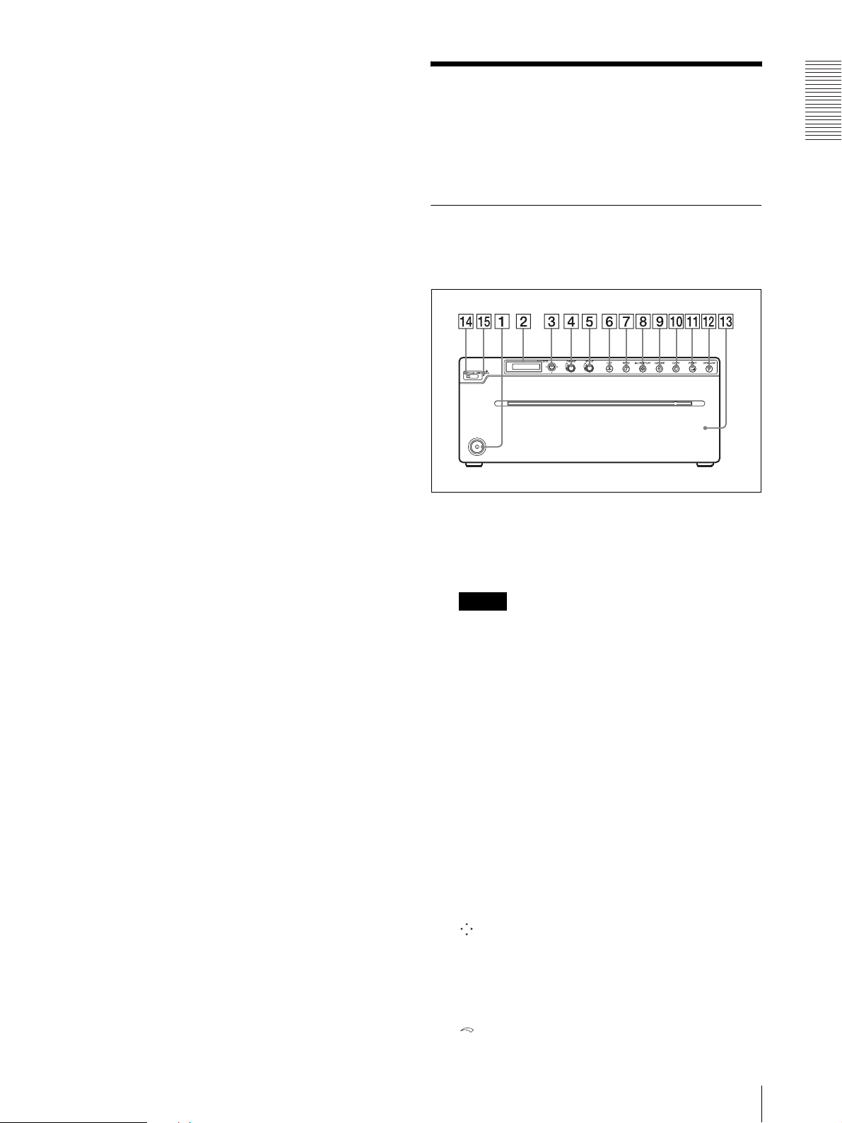
Location and Function of Parts and Controls
For more details, see the referenced page numbers
enclosed in parentheses ().
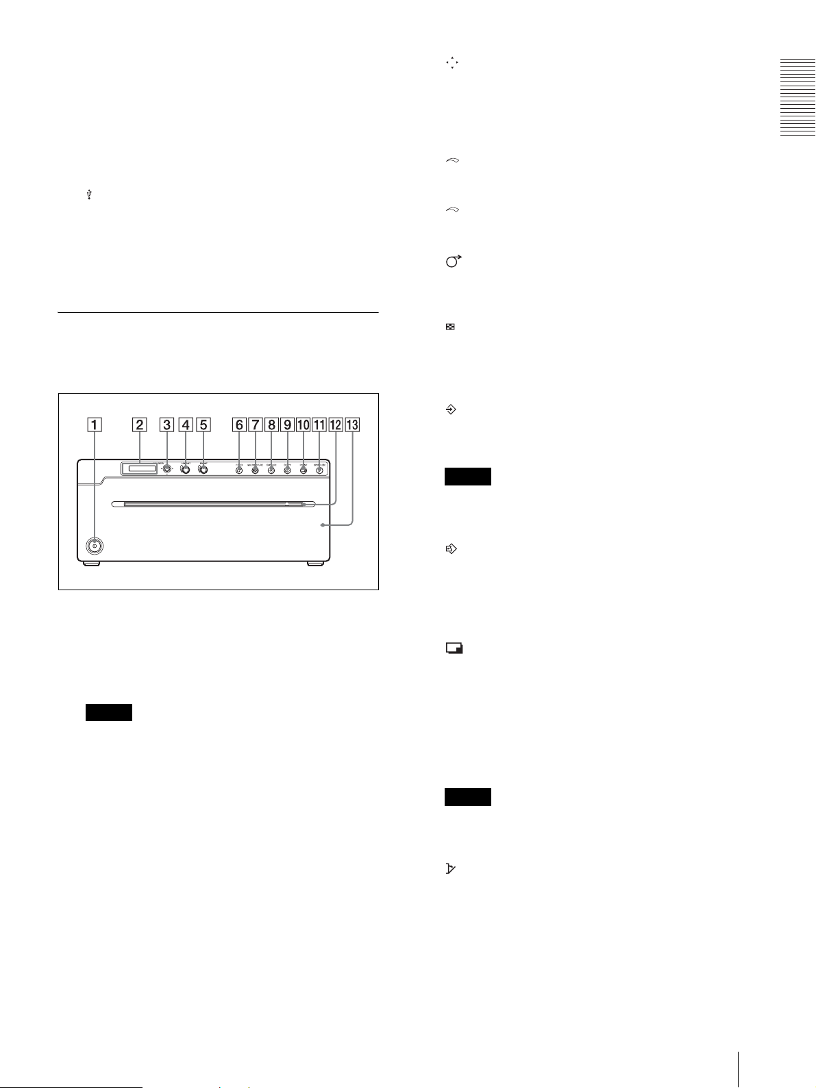
UP-991AD
Front Panel
A !Power on/off switch (page 15, 25, 28, 31, 37,
38)
Press to turn on the printer. The LCD display
backlight and button backlight turn on.
Getting Started
Note
When the unit is turned on/off, or the main power is
turned off and turned on again, turn on the unit after
about five seconds.
B Printer window display (LCD: liquid crystal
display) (page 25, 28, 31, 35)
The back light lights in green during normal unit
operation. Also, the kind of printing paper used is
shown on the right of the display when the paper
door opens or closes.
For detailed information on the paper, see “Loading
Paper in the Unit” on page 15 and “Paper” on page
38.
If an error occurs, a corresponding alarm message
is displayed.
During menu operations, menu items and settings
are displayed.
C Menu lever (page 20, 25, 37)
Navigate menus by tilting up, down, left or right.
Also, by pressing the center of the lever, you can
change the standby status to menu mode, or select
menu setting items.
D CONTRAST (contrast) dial (page 32)
Location and Function of Parts and Controls
11
Adjusts the contrast of printouts.
L OPEN/CLOSE button (page 15, 28, 37)
Press to open or close the paper door. While
E BRIGHT (brightness) dial (page 32)
printing, press to cancel the print job.
Adjusts the brightness of the printouts.
M Paper door
Getting Started
F CUT button (page 16, 28)
Press to cut the paper at the end of a print job using
the internal paper cutter.
While printing, press to cancel the print job.
Open to install or replace printing paper, and to
clean the thermal head and platen roller. Use the
OPEN/CLOSE button to open or close the paper
door.
G FEED button (page 16, 28, 28)
Hold down to feed paper. While printing, press to
cancel the print job.
H MULTI PICTURE (multi-picture) button
(page 29)
Toggles between the multi-picture mode and
single-picture mode.
Note
This function is available only when printing a
video image.
I CAPTURE button (page 29, 34)
In the multi-picture mode, press to store the print
image in the memory of the unit.
When “STR:CAPT” is selected in the “STR.KEY”
menu, image data captured from the video signals is
stored in the USB Flash Drive.
Note
This function is available only when printing a
video image.
J COPY button (page 30, 32)
Press to print a copy of the last printed image. Prints
only one paper regardless of the paper number set
in the “QTY” menu. This function is not available
in the multi-picture mode.
K PRINT button (page 28, 34)
In the multi-picture mode, images stored in the
memory of the unit (by the CAPTURE button) are
printed sequentially on a single paper.
In the single-picture mode, press to print the image
displayed on the monitor. When you press the
PRINT button, the displayed image is stored in the
memory of the unit and printed.
When “STR:PRNT” is selected in the “STR.KEY”
menu, the image is stored in a USB Flash Drive
after printing
Note
This function is available only when printing a
video image.
N USB Flash Drive terminal
Connect a USB Flash Drive to this terminal.
O USB Flash Drive access lamp
Displays USB Flash Drive access status, or verifies
any non-compatible USB devices.
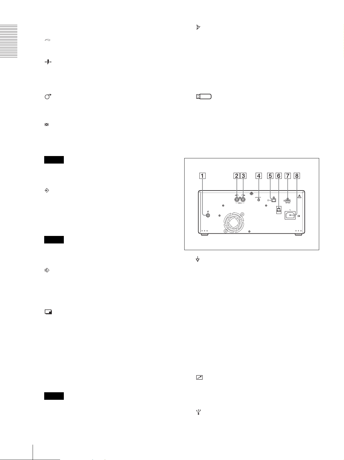
Rear Panel
A Equipotential terminal
Used to connect to the equipotential plug to bring
the various parts of a system to the same potential.
Refer to “Important safeguards/notices for use in
the medical environments” on page 3.
B t VIDEO IN (input) connector (BNC type)
Connect to the video output connector of video
equipment.
C T VIDEO OUT (output) connector (BNC type)
Connect to the video input connector of a monitor,
etc.
Outputs the video signal which is input from the
VIDEO IN terminal (Automatic termination is
provided).
D REMOTE connector (page 17, 30)
Connects the Remote commander RM-91 or Foot
switch FS-24 (separately sold) for controlling print
operation from a distance.
E USB connector (4-pin connector)
12
Location and Function of Parts and Controls
Use the USB cable to connect a computer with a
USB (USB 2.0 compliant) interface to this
connector.
F USB Cable Clamper
Holds and secures the USB cable connected to the
USB connector.
G OPTION terminal
Used for future expansion functions.
H - AC IN connector
Use the appropriate power cord for your local
power supply (not supplied).
C Menu lever (page 20, 25, 37)
Navigate menus by tilting up, down, left or right.
Also, by pressing the center of the lever, you can
change the standby status to menu mode, or select
the menu setting items.
Getting Started
D CONTRAST (contrast) dial (page 32)
Adjusts the contrast of printouts.
E BRIGHT (brightness) dial (page 32)
Adjusts the brightness of printouts.
F FEED button (page 16, 24, 28)
Hold down to feed paper. While printing, press to
cancel the print job.
UP-971AD
Front Panel
A !Power on/off switch (page 15, 25, 28, 31, 37,
38)
Press to turn on the printer. The LCD display
backlight and backlight of the button are lit when
the printer is on.
Note
When the unit is turned on/off, or the main power is
turned off and turned on again, turn on the unit after
about five seconds.
G MULTI PICTURE (multi-picture) button
(page 29)
Toggles between the multi-picture mode and
single-picture mode.
H CAPTURE button (page 29, 34)
In the multi-picture mode, press to store a print
image in the memory of the unit.
Note
This function is available only when printing a
video image.
I COPY button (page 30, 32)
Press to print a copy of the last printed image. Prints
only one paper regardless of the paper number set
in the “QTY” menu. This function is not available
in the multi-picture mode.
J PRINT button (page 28, 34)
In the multi-picture mode, images stored in the
memory of the unit (by the CAPTURE button) are
printed sequentially on a single paper.
In the single-picture mode, press to print the image
displayed on the monitor. When you press the
PRINT button, the displayed image is stored in the
memory of the unit and printed.
B Printer window display (LCD: liquid crystal
display) (page 25, 28, 31, 35)
The backlight lights in green during normal unit
operation. The printing paper type used is shown on
the right of the display when the paper door opens
or closes.
For detailed information on the paper, see “Loading
Paper in the Unit” on page 15 and “Paper” on page
38.
If an error occurs, a corresponding alarm message
is displayed.
During menu operations, menu items and settings
are displayed.
Note
This function is available only when printing a
video image.
K OPEN/CLOSE button (page 15, 28, 37)
Press to open or close the paper door. While
printing, press to cancel the print job.
L Paper Cutter
Cut the paper as each image is printed.
M Paper door
Location and Function of Parts and Controls
13

Open to install or replace printing paper, and to
clean the thermal head and platen roller. Use the
OPEN/CLOSE button to open or close the paper
door.
Refer to “Warning on power connection” on page 7
and “Warning on power connection for medical
use” on page 7.
Getting Started
Rear Panel
A Equipotential terminal
Used to connect to the equipotential plug to bring
the various parts of a system to the same potential.
See “Important safeguards/notices for use in the
medical environments” on page 3.
B t VIDEO IN (input) connector (BNC type)
Connect to the video output connector of video
equipment.
C T VIDEO OUT (output) connector (BNC type)
Connect to the video input connector of a monitor,
etc.
Outputs the video signal which is input from the
VIDEO IN terminal (Automatic termination is
provided).
D REMOTE connector (page 17)
Connects the Remote commander RM-91 or Foot
switch FS-24 (separately sold) for controlling print
operation from a distance.
E USB connector (4-pin connector)
Use the USB cable to connect a PC with a USB
(USB 2.0 compliant) interface to this connector.
F USB Cable Clamper
Holds and secures the USB cable connected to the
USB connector.
G OPTION terminal
Used for future expansion functions.
H - AC IN connector
Use the appropriate power cord for your local
power supply (not supplied).
14
Location and Function of Parts and Controls

Preparation
Loading Paper in the Unit
2
Press the OPEN/CLOSE button to open the paper
door.
Caution
Do not touch any unit circuitry and the patient at the
same time.
If the unit malfunctions, it may generate voltage that
could be harmful to the patient.
Notes
• Do not touch the print surface of thermal printing
paper when loading it. Fingerprints, perspiration and
creases that may result will lower the print quality.
• Use only UPP-210 series or UPT-210BL printing
paper (page 38).
• If you use the UPP-210 series, set the menu according
to the paper (page 38).
1
Press the power on/off switch to turn the unit on.
3
Place the printing paper roll on the tray.
Using UPP-210SE/UPP-210HD
Remove label
and pull out 15
to 20 cm (about
6 to 8 inches).
Place the paper with the heat sensitive side facing
up. The printer will not print if the paper is
reversed.
Using UPT-210BL thermal film
* Cannot be used with the UP-971AD. Doing so may
cause a malfunction.
Preparation
The LCD display shows the message “SONY UP991AD” for the UP-991AD and “SONY UP971AD” for the UP-971AD.
Notes
• The LCD display backlight lights in amber and
shows the message “EMPTY” when no printing
paper is loaded.
• The LCD display backlight lights in amber and
shows the message “DOOR” when the paper door
is open.
Correctly Inserted
Remove label
and pull out
15 to 20 cm
(about 6 to 8
inches).
Incorrectly Inserted
Place the paper with the heat sensitive side facing
up. The printer will not print if the paper is
reversed.
Loading Paper in the Unit
15

Preparation
4
Insert the paper into the groove of the paper tray
and pull it out through the paper exit.
Note
Place the paper near the center of the groove of the
paper tray (inside of the guide). Note that paper
jams may occur if the paper is placed at the edge of
the groove of the paper tray.
UP-971AD
After loading paper, press the FEED button to feed
out 15 to 20 cm (6 to 8 inches) of paper. Then use
the paper cutter to remove it.
FEED Button
Note
Note
Pull out the printing paper to remove any slack and
possible creases.
5
Press the OPEN/CLOSE button to close the paper
door.
You can also push the paper door to close it.
6
Remove the paper leading edge.
UP-991AD
After loading paper, press the FEED button to feed
out 15 to 20 cm (6 to 8 inches) of paper and press
the CUT button to remove it.
FEED Button
CUT Button
To use the UPT-210BL after printing with UPP-210SE/
UPP-210HD, clean the thermal head before printing.
Otherwise, fine stripes may appear on printouts.
16
Loading Paper in the Unit
15 to 20 cm

Connections
• Connect the AC power cord last.
You can connect this unit to video devices and
computers. When connecting, see the operating
instructions of the connecting devices.
Warning
Using this unit for medical purposes
This equipment's connectors are not isolated.
Do not connect any device other than one which
conforms to IEC60601-1.
When an information technology device or AV device
that uses an alternating current is connected, current
leakage may result in an electric shock to the patient or
operator.
If use of such a device is unavoidable, isolate its power
supply by connecting an isolation transformer, or by
connecting an isolator between the connecting cables.
After implementing these measures, confirm that the
reduced risk now conforms to IEC60601-1.
Connecting to video devices
Video equipment
Connecting cable
to VIDEO IN
(BNC)
to REMOTE
to video output
connector
to video input
connector
Connecting cable
to VIDEO OUT
(BNC)
Color/black and
white video monitor
Connections
to AC IN
Notes
• Turn off the power of each device before making any
connections.
Remote commander
RM-91 (separately sold)
Foot switch
FS-24 (separately sold)
AC power
cord (not
supplied)
to wall outlet
Connecting to video devices
17

Connecting to a computer
When you use Windows 7/8:
Before connecting this unit to the computer, install the
supplied printer driver to the computer. For installing,
refer to the Install Guide of the supplied CD-ROM, and
the Readme file.
Connections
Notes
• Before connecting the unit to a computer, turn off the
unit, computer, monitor, and all peripheral devices
connected to the computer.
• Before connecting the unit to the computer, disconnect
the power cord from the unit. Connect the power cord
to the unit only after connecting the unit and the
computer.
• Follow the connection procedures described in the
computer manual.
• Make sure that the cables are connected securely at
both ends.
• The unit drive software provided with the unit is not
suitable for using the unit connected to a network.
• Printer operation is not guaranteed when connecting
to the computer using the USB cable via a hub.
• Two or more units cannot be connected to a single
computer.
Connecting to the USB Connector
Note
When this unit is turned on, do not set a connected
computer to standby (suspended) or pause mode, as it
may cause a malfunction.
to (USB)
connector
USB connecting
cable
Install the printer driver to the computer
When you use Windows XP/Windows Vista:
After connecting this unit to the computer, turn on this
unit. For installing, refer to the Install Guide of the
supplied CD-ROM, and the Readme file.
18
Connecting to a computer

Operation
Adjustments and Settings Using the Menu
You can carry out adjustments and settings to meet your
requirements. Those settings and adjustments are
retained even if the unit is turned off.
You can set up the unit according to its intended
purpose, connected equipment or your individual
preferences.
You can store up to three user settings.
Operation
Adjustments and Settings Using the Menu
19

Menu structure and layer
The contents displayed on the LCD change in sequence
as you turn the menu lever, as shown in the following
menu flow chart, and you can make the settings for each
menu item.
Menus have a layer structure. Turn the menu lever to the
right to go to the lower layer, or to the left to return to the
upper layer.
On the LCD, “-” appears at the beginning of each menu
item name in the lower layer.
UP-991AD Menu Outline UP-971AD Menu Outline
READY
HISTORY
PRT.HELP LIST
Operation
ADJUST BRIGHT
VIDEO ASPECT
DIGITAL DRIVER
PRT.MENU
PREF. BACWRD
CLEAN.TH
CONFIG. AUT.CUT
SERIAL.N
HELP.1
HELP.2
HELP.3
HELP.4
HELP.5
CONTRA
GAMMA
SHARP
TONE
AUT.PRT
COLOR
FIELD
INTRPT
N.MULTI
SCALE
SIDE
STR.KEY
PRT.POS
START.H
START.V
END.H
END.V
RESIZE
BLANK
BORDER
INFO
INVERT
MIRROR
QTY
AUT.LCK
BEEP
CLOCK
PP.TYPE
RESET
LOAD
SAVE
READY
HISTORY
PRT.HELP LIST
HELP.1
HELP.2
HELP.3
ADJUST BRIGHT
CONTRA
GAMMA
SHARP
TONE
VIDEO ASPECT
AUT.PRT
COLOR
FIELD
INTRPT
N.MULTI
SCALE
SIDE
PRT.POS
START.H
START.V
END.H
END.V
DIGITAL DRIVER
RESIZE
PRT.MENU
PREF. BACWRD
BORDER
INFO
INVERT
MIRROR
QTY
CLEAN.TH
CONFIG. AUT.LCK
BEEP
FEED
PP.TYPE
RESET
LOAD
SAVE
SERIAL.N
20
Adjustments and Settings Using the Menu

Menu List
The following list explains the functions of each menu
item. Factory settings are surrounded by [ ].
1st layer Explanation 2nd layer Explanation
HISTORY Displays the operation history
of the most recently used
menus, up to a maximum of
five menus. "NO ITEM" is
displayed in the initial status.
PRT.HELP Prints an explanation of the
operating methods. (English
only)
ADJUST Menu for picture adjustment BRIGHT Adjusts the printout brightness. The adjustment range is - 64 to [0], [0]
LIST Prints a list of explanations about various operating methods. (in
HELP1 An explanation about "Printing two, four or six images on one sheet."
HELP2 An explanation about "Contrast and Brightness Control."
HELP3 An explanation about "Visual Adjustment of Brightness, Contrast,
HELP4
UP-991AD
only
HELP5
UP-991AD
only
CONTRA Adjusts the printing contrast. The adjustment range is - 64 to [0], [0] to
GAMMA Switches the gamma.
SHARP Sharpens outlines in pictures.
TONE Adjusts the density of neutral tints.
English)
Sharpness, Tone."
An explanation about "Printing to film."
An explanation about "Storing Image Data on a USB Flash Drive."
to + 64.
When the setting items are displayed on the LCD (PRINT button
flashes), press the PRINT button to print nine pictures at varying levels
of brightness.
+ 64.
When the setting items are displayed on the LCD (PRINT button
flashes), press the PRINT button to print nine pictures at varying levels
of contrast.
GAMA3: Hard
GAMA2: Soft
[GAMA1: Standard]
You can adjust the sharpness of outlines. The adjustment range is [0] to
14. The larger the number, the sharper the outlines. When the setting
items are displayed on the LCD (PRINT button flashes), press the
PRINT button to print eight pictures at varying levels of sharpness.
The adjustment range is - 32 to [0], [0] to + 32.
When the setting items are displayed on the LCD (PRINT button
flashes), press the PRINT button to print nine pictures at varying levels
of tone.
Operation
Adjustments and Settings Using the Menu
21

1st layer Explanation 2nd layer Explanation
VIDEO Menu for video images ASPECT
a)
Switches the aspect ratio.
ASPT:1:1: Prints pictures with 1:1 aspect ratio.
[ASPT:4:3]: Normally set this status.
AUT.PRT
You can switch between automatic and manual printing in multi-picture mode.
AUTP:ON: Prints pictures without pressing the PRINT button. Printing
starts automatically as soon as the number of images specified in the
multi picture mode is captured.
[AUTP:OFF]: Prints by pressing the PRINT button.
COLOR Switches according to the input signal.
COLR:ON: For printing images from color video signals.
[COLR:OFF]: For printing images from black and white video signals.
Also, switches the file format (color/black and white) for saving to USB Flash
Drive. To save in color, select "CAPT" in "STR.KEY." (UP-991AD only)
FIELD Switches the memory mode.
FIED:ON: When a picture containing rapid motion results in a doublyblurred print, select this.
[FIELD:OFF]: Normally select this.
INTRPT Switches the operation when you cancel printing.
Single-picture mode:
INTR:ON: If you press the PRINT button again to cancel a print
Operation
operation and want to print a screenshot at the moment the PRINT
button is pressed, select this.
INTR:OFF: Even when you press the PRINT button again during a
print operation, printing continues. If you want to print a screenshot at
the moment the PRINT button is pressed after the print operation
finishes, select this.
Multi picture mode:
INTR:ON: If you press the CAPTURE button again to cancel a print
operation and want to print a screenshot at the moment the CAPTURE
button is pressed, select this. The screenshot is printed at the position
that the number flashing in the LCD display indicates.
INTR:OFF: Even when you press the CAPTURE button again during a
print operation, printing continues.
N.MULTI Specify the number of printed pictures on a paper.
MULTI:6: Six pictures on a paper (divided into six sections)
MULTI:4: Four pictures on a paper (divided into four sections)
[MULTI:2]: Two pictures on a paper (divided into two sections)
SCALE Set the scale of enlargement for printing pictures.
The modification range is [1.0] to 2.0, in 0.1 increments.
SIDE
b)
Switches the print direction.
SIDE:ON: Prints pictures sideways.
Prints pictures in the way they appear on the monitor screen.
STR.KEY
UP-991AD
only
[SIDE:OFF]:
Sets the mode by which to save picture data to a USB Flash Drive.
[STR:PRNT]: Saves pictures to USB Flash Drive by pressing the PRINT
button. The picture will be saved after printing.
STR:CAPT: Saves pictures to USB Flash Drive by pressing the
CAPTURE button.
PRT.POS Prints video images with coordinate lines for adjusting the printing area.
START.H Specifies the horizontal starting point of the printing range.
S.H: 0~[6]~719 (NTSC)
0~[8]~719 (PAL)
START.V Specifies the vertical starting point of the printing range.
S.V: 0~[22]~503 (NTSC)
0~[28]~603 (PAL)
END.H Specifies the horizontal ending point of the printing range.
E.H: 0~[719] (NTSC)
0~[707]~719 (PAL)
END.V Specifies the vertical ending point of the printing range.
E.V: 0~[500]~503 (NTSC)
0~[598]~603 (PAL)
22
Adjustments and Settings Using the Menu

1st layer Explanation 2nd layer Explanation
DIGITAL Menu for digital images DRIVER Switches the printer driver.
[DRV:991]: For UP-991AD and UP-971AD. (UP-991AD only)
[DRV:971]: For UP-991AD and UP-971AD. (UP-971AD only)
DRV:990: For UP-990AD, a previous model.
DRV:970: For UP-970AD, a previous model.
RESIZE You can select printing with or without enlargement.
[RSIZ:OFF]: Prints the original size.
RSIZ:ON: Prints with enlargement to the paper size specified by the
printer driver.
PRT.MENU Prints a list of the current
setting items.
MENU:OK : Prints a picture
by pressing the menu lever.
c)
PREF. Menu for setting the printout
method
BACWRD
Switches the printing direction.
[BAC:AUTO]: For paper printing, prints pictures from the bottom.
For film printing, prints pictures from the top.
BAC:ON: Prints pictures from the top.
BAC:OFF: Prints pictures from the bottom.
BLANK
UP-991AD
only
Sets the upper and lower margin widths of the printing paper.
You can adjust the margin from [ 0 ] to 15. Increasing one value adds 5
mm to each upper and lower margin. The maximum width of each
upper and lower margin is 75 mm.
BORDER Selects whether to render the frame in black or white.
[BD:AUTO]: Renders in black for film printing and in white for paper
printing.
BD:BLACK: Renders in black.
BD:WHITE: Renders in white.
INFO Prints information under the picture.
[INFO:OFF]: No information added.
INFO:ADJ: Adds the picture adjustment value.
INFO:CLK: Adds date and time information. (UP-991AD only)
INFO:STR: Adds the path and file name of saved pictures to USB Flash
Drive. (UP-991AD only)
INVERT Inverts black and white.
INV:NEG: Prints with black and white reversed.
[INV:POS]: Normal (without reversing black and white)
MIRROR Prints the picture with left and right reversed.
MIRR:ON: With right and left reversed.
[MIRR:OFF]: Normal (without reversing right and left)
QTY Sets the number of prints.
QTY:[1]-10: Sets the number of prints for an image.
CLEAN.TH Clean the printer thermal head.
CLEAN OK: Start cleaning by
pressing the menu lever.
Operation
Adjustments and Settings Using the Menu
23

1st layer Explanation 2nd layer Explanation
CONFIG. Settings for operations AUT.CUT
UP-991AD
only
AUT.LCK Switches whether to lock the BRIGHTNESS and CONTRAST dials
BEEP Switches the beep sound on or off. The alarm buzzer always sounds,
CLOCK
UP-991AD
only
Operation
FEED
UP-971AD
only
PP.TYPE Selects the type of paper media. For UPT-210BL, this setting is not
RESET Returns to the factory default setting. (Initializing)
LOAD Calls up a registered menu setting.
SAVE Registers three types of menu setting.
SERIAL.N Displays the product serial
number.
Switches whether the printer automatically cuts the printed paper after
printing or not.
ACUT:OFF: Cuts the paper with the cut button.
[ACUT:ON]: Cuts the paper automatically.
automatically or not.
ALCK:ON: Locks automatically. To release, hold down the menu lever
for three seconds while in STANDBY status. If there is no operation for
more than 10 seconds during the unlocked status, the dials will be
locked.
ALCK: OFF : Does not lock automatically. Holding down the menu
lever for three seconds switches locking/unlocking of the dial.
regardless of the setting.
BEEP:OFF: No beep sound.
[BEEP:ON]: Beep sound.
Sets the time.
Set the year: Change items turning the menu lever up or down, and
adjust them while "Y: XXXX" is displayed, then press the menu lever to
set.
You can set the month, hour, minute second in the same way as above.
To reset, turn the menu lever to the left.
The initial setting is Standard World Time.
Switches the paper sending length after printing.
[FEED:ON]: Sends the paper with margin after printing.
FEED:OFF: Reduces the paper sending length or prints a number of
images without paper cutting. Since the margin for a paper is small, you
can make more prints from one paper set. Cut the paper after pressing
the FEED button.
required.
[P.TYPE:HD]: For UPP-210HD
P.TYPE:SE: For UPP-210SE
RESET:OK: Returns to the factory default setting.
LOAD:3: Calls up the menu setting registered in “SAVE: 3”.
LOAD:2: Calls up the menu setting registered in “SAVE: 2”.
[LOAD:1]: Calls up the menu setting registered in “SAVE: 1”.
SAVE:3: Register as number 3.
SAVE:2: Register as number 2.
[SAVE:1]: Register as number 1.
24
Adjustments and Settings Using the Menu

a) The aspect ratio is as follows.
I
When ASPT:4:3 is selected
When ASPT:1:1 is selected
b) The print direction of images is as follows.
1
Press the power on/off switch to turn the unit on.
The back light on the LCD lights in orange, and
then changes to green.
LCD
mage displayed on the monitor
Printouts
When SIDE:OFF is selected. When SIDE:ON is selected
In paper printing
c) The printing direction determined by the setting is as
follows.
2
Confirm that “READY” is displayed on the LCD,
and press the menu lever.
The unit enters the menu mode.
The top item of the “HISTORY” menu is displayed.
3
Display “VIDEO” by turning the menu lever up or
down.
Operation
When BAC:OFF is selected When BAC:ON is selected
Basic Menu Operations
This section describes the basic menu operations
common to each menu. As an example, the following
procedure describes how to set the printing direction.
4
Display “ASPECT” by turning the menu lever to
the right once. Then display “SIDE” by turning the
menu lever down several times.
5
Display “SIDE:OFF” by turning the menu lever to
the right once.
Adjustments and Settings Using the Menu
25

6
Press the menu lever.
To continue menu operations
Make settings by repeating steps 3 to 7.
To end menu operation
1
After step 7, exit the menu mode by turning the
menu lever twice to the left.
Registering Menu Settings
The unit enters the mode in which you can select
the printing direction.
“SIDE:OFF,” which is the factory setting, is
displayed on the LCD. “SIDE:OFF” is the currently
selected setting.
In this menu operation, you will change the setting
to “SIDE:ON.”
7
Display “SIDE : ON” by turning the menu lever up
or down, then press the menu lever.
Operation
You can store up to three sets of menu settings, which
you can load at any time.
The unit retains these settings even if you turn off the
power.
Note
When you use the unit for the first time after you
purchase it, factory settings are registered in all three of
the stored selections.
Registering new settings
1
Make all of the required settings.
2
Display “CONFIG” by turning the menu lever up or
down.
3
Display “-SAVE” by turning the menu lever to the
right and up or down, and then press the menu lever.
4
By turning the menu lever up or down, display the
number to which you want to register the settings,
and then press the menu lever again.
The settings made in step 1 are registered in the
number displayed in this step.
“SIDE:ON” is registered as the printing direction.
“-SIDE” reappears on the LCD.
Note
If about 20 seconds elapse without making any
menu lever operation after you have displayed the
menu item or setting, the display returns to
“READY” on the LCD and the unit exits the menu
mode. In such a case, the setting of “-SIDE” will
not change.
To cancel the setting
1
Return the LCD display to “SIDE” by turning the
menu lever to the left.
26
Adjustments and Settings Using the Menu
Loading the desired settings
You can load the desired settings.
1
Confirm that “READY” is displayed on the LCD,
and press the menu lever.
2
Display “CONFIG” by turning the menu lever up or
down.
3
Display “-LOAD” by turning the menu lever to the
right and up or down, then press the menu lever
again.
4
By turning the menu lever up or down, display the
number in which the settings you want to load are
registered, then press the menu lever again.
The settings registered in the number displayed in
this step are loaded.

When you change the loaded settings
The unit operates according to the changed settings. In
this case, the unit operates at the currently loaded
settings, until you load another set of settings, even if
you turn off the unit. Loading another set of settings will
clear the previously loaded settings.
To retain previously loaded settings
Example: Settings registered as “SA:1” are loaded and
settings are changed. To retain the original settings of
“SA:1” and to register the new settings as “SA:2,”
proceed as follows.
3
Display “LIST” by turning the menu lever to the
right, then press the menu lever. A list of operating
methods/explanations will be printed.
4
Display a desired menu by turning the menu lever,
then press the menu lever. The explanation of the
operating method is printed.
The explanation of the operating method is in
English only.
Printing the Menu List
1
Load the settings of “LOAD:1” following the
procedure for loading the desired settings.
2
Change the loaded settings as required.
3
Select “SAVE:2” following the procedure for
registering the settings.
4
Press the menu lever.
The settings, changed in step 2, are registered as
“SA:2” (No.2).
Call up the last-used menus
You can store the five most recently used menus in
HISTORY.
This feature is convenient for calling up frequently used
menus.
1
Confirm that “READY” is displayed on the LCD,
then press the menu lever.
2
Confirm that “HISTORY” is displayed, then turn
the menu lever to the right.
You can make a printout of the current menu settings.
1
Confirm that “READY” is displayed on the LCD,
then press the menu lever.
HISTORY is displayed.
2
Display “PRT.MENU” by turning the menu lever
up or down.
3
Display “MENU:OK” by turning the menu lever to
the right once, and then press the menu lever.
The unit starts printing the current menu settings.
Operation
3
The latest-used menu is displayed.
Display a desired menu by turning the menu lever
up or down.
4
Press the menu lever and change settings if desired.
“NO ITEM” is displayed if no menu has been used,
i.e., in the initial status.
Printing explanations of operating
methods
You can print out explanations of easy operating
methods.
1
Confirm that “READY” is displayed on the LCD,
then press the menu lever.
2
Display “PRT.HELP” by turning the menu lever up
or down.
Adjustments and Settings Using the Menu
27

Printing
The back light on the LCD lights in orange, and
then changes to green. “READY” is displayed on
the LCD.
The difference between film printing and paper
printing
In film printing, images are printed from the top.
Film print (UPT-210BL) Paper print (UPP-210HD,
UPP-210SE)
2
Start the video source.
* When “BAC:AUTO” is set in “PREF,” “-BACWRD”
Film printing has a function which prints a margin in
black.
Operation
When “BD:BLACK”
is set in “PREF,”
“-BORDER”
Before Starting a Print Job
Always check the following points:
• Unit connected correctly? (page 17)
• Paper loaded correctly? (page 15)
• Menu settings and menu adjustments done correctly?
(page 19)
• In the case of a video image, is the video source signal
input?
When “BD:WHITE”
is set in “PREF,”
“-BORDER”
Starting a Print Job of Video Images
You can set up the printing direction, image size, and
various settings for printing, using the menu. This
section describes operations after completing the
various settings using the menu.
This operation is done using the controls of the
video equipment which you are using as the source.
3
Press the PRINT button when the image you want
to print is on the video monitor.
The image displayed at the instant you press the
button will be printed.
When a message is displayed on the LCD
If a problem occurs, the back light on the LCD will light
in amber and an error message stating the problem is
displayed on the LCD.
Message Cause and remedy
EMPTY Paper is not loaded. Load paper.
DOOR The paper door is open. Close the
When the unit stops printing during printing
When continuously printing images of high density,
such as mostly dark images, the thermal head protection
circuit may shut down the unit to prevent the thermal
head from overheating. In such a case, the message
“COOLING” is displayed on the LCD.
Wait until the thermal head cools down and the message
disappears.
To cancel a print job in progress
To cancel a print job in progress, press the OPEN/
CLOSE button, FEED button or CUT button.
LCD
paper door.
28
1
Press the power on/off switch to turn the unit on.
Printing
To feed paper
To feed paper, press the FEED button. The unit will
continue to feed paper as long as you hold down the
FEED button. Do not attempt to pull paper out of the
unit by hand.

To cut paper (UP-971AD)
Hold the paper at a position which is 15 to 30 cm away
from the paper exit, then pull it up in the direction the
arrow indicates.
How the paper is cut off varies depending on positions
you hold on the paper, directons in which you pull up the
paper, and speeds at which you pull it up.
Cut off the paper according to the print size.
Paper currently selected
You can confirm the paper currently selected on the
LCD. The type of printing paper used is displayed on the
right of the display when the paper door opens or closes.
UPT-210BL
2
When the MULTI PICTURE button on the front
panel is pressed, the LCD display switches to the
multi-picture mode.
When “MULTI:2” is selected:
: 1
indicates that “1” flashes.
3
Press the CAPTURE button in step 3 of “Starting a
Print Job of Video Images” in the section “Analog
mode” (page 28).
This captures the displayed image and assigns it the
flashing number.
The next available number flashes in the LCD
display.
When “MULTI:2” is selected:
: The captured image is assigned “1” and
“2” starts flashing.
4
Press the CAPTURE button again to capture the
displayed image.
If the “AUT.PRT” menu is ON, printing starts
automatically as soon as the number of images
specified by “MULTI:(2/4/6)” is captured. If the
menu is OFF, press the PRINT button to start
printing.
Operation
UPP-210HD
UPP-210SE
Note
If “AUCT:ON” is selected in the “AUT.CUT”
menu, quickly remove the prints that have been cut.
Otherwise, the cut prints may block the paper exit
and cause a paper jam to occur.
If the printout image is blurred
A rapidly moving image may be blurred when printed.
Should this occur, make a printout with "FIED:OFF"
selected in the "VIDEO" "-FIELD" menu item.
Printing two, four or six images on one
sheet
Use “N.MULTI” item of the menu to capture and print
two to six different images on one sheet.
1
In the “VIDEO” “-N.MULTI” menu, display
“MULTI:2” – “MULTI:6” according to the number
of images you want to print on one sheet, then press
the menu lever.
Capturing two images (“MULTI:2 selected in
“N.MULTI”)
Image captured
in step 3
Printing direction
Capturing four images (“MULTI:4 selected in
“N.MULTI”)
Capturing six images (“MULTI:6 selected in
“N.MULTI”)
“INFO:ON” selected in “INFO” menu
In multi-picture mode, if “INFO:ON” is selected in the
“INFO” menu, information about the last captured
image is printed in the margin.
Image captured
in step 4
Printing
29

Example: If “N.MULTI” is set to “MULTI:6” and six
I
images are captured, “IMAGE:6” is printed in the
margin as the information for that image.
Multi-picture mode
When an image you want to capture appears, press the
remote switch to save a screenshot of that instant in the
memory of the unit.
Printing starts automatically when the number of images
set in the “MULTI” menu have been captured.
Note
IMAGE:6
[Image
Information]
Even if “INTRA:ON” is selected in the "VIDEO" "INTRPT" menu, pressing the remote switch performs
the same action as pressing the PRINT button or
CAPTURE button in each mode.
Making Copies of the Last Printout
Press the COPY button in the single-picture mode. Press
the PRINT button in the multi-picture mode. The unit
makes a copy of the last printout. Each press of the
button prints one paper regardless of the paper numbers
set in the “QTY” menu.
Operation
Note
If you press the COPY button immediately after turning
the power on, the alarm buzzer will sound as nothing is
stored in memory. In this case, you cannot start a copy
job.
Selecting the printing direction
You can select the printing direction using the “SIDE”
menu item.
To print in the same direction as the one
displayed on the video monitor
Select “SIDE:OFF” from “SIDE.”
To print an image rotated counterclockwise
Select “SIDE:ON” from “SIDE.”
mage displayed on the video monitor
Making copies of the same image continuously
Press the COPY button in the single-picture mode, or
press the PRINT button in the multi-picture mode. And
press the COPY or PRINT button while copying the first
printout. When you press the COPY or PRINT button
once, a buzzer sounds and one printout will be made.
The number of printouts accords to how many times you
press the COPY or PRINT button. Each press of the
button prints one paper regardless of the paper numbers
set in the “QTY” menu.
To interrupt copying
To cancel a print job in progress, press the OPEN/
CLOSE button, FEED button or CUT button.
To make copies in different directions
You can copy the image stored last in a different
direction. Before pressing the COPY button in the
single-picture mode or the PRINT button in the multipicture mode, select the printing direction.
To print from a remote location
If the Remote commander RM-91 is connected to the
REMOTE connector on the rear panel, you can start
printing at a short distance from the unit by pressing the
remote switch.
Single-picture mode
When an image you want to print appears, press the
remote switch. The screenshot of that instant is printed.
Printouts
When “SIDE:OFF” is selected
When “SIDE:ON” is selected
To set the range of the image to be
printed
1
When the “VIDEO.” “-PRT.POS,” “P.POS:OK”
menu is displayed, press the menu lever. The unit
prints the video image with coordinate lines for
adjusting the printing area.
2
On the printout, decide the starting point (upper
left) and ending point (lower right) of the printing
area, and check the coordinate values of the points.
30
Printing

3
Display “S.H:” in “-START.H” by operating the
menu. Then enter the horizontal start point
coordinate by turning the menu lever up or down,
and press the menu lever.
4
Display “S.V:” in “-START.V” by operating the
menu. Then enter the vertical start point coordinate
by turning the menu lever up or down, and press the
menu lever.
5
Display ”E.H:” in “-END.H” by operating the
menu. Then enter the horizontal end point
coordinate by turning the menu lever up or down,
and press the menu lever.
6
Display “E.V:” in “END.V” by operating the menu.
Then enter the vertical end point coordinate by
turning the menu lever up or down, and press the
menu lever.
7
Display “READY” by turning the menu lever
several times to the left, and then press the PRINT
button. Confirm that the specified area of the
picture is printed.
Start point (START.H, START.V)
100
100
200
300 400
200
300 400
100
100
500
500
600
600
This explanation is about the operation after finishing
these settings.
1
Press the power on/off switch to turn the unit on.
The back light on the LCD lights in orange, and
then changes to green. “READY” is displayed on
the LCD.
LCD
2
Operate the application software in the computer,
and start a print job.
Operation
When the unit stops printing during printing
When continuously printing images with high density
such as mostly dark images, the thermal head protection
circuit may shut down the unit to prevent the thermal
head from overheating. In such a case, the message
700
700
“COOLING” is displayed on the LCD.
Wait until the thermal head cools down and the message
disappears.
200
200
300
300
400
400
500
500
End point (END.H,END.V)
Printing a captured image with
enlargement
You can set the “VIDEO” – “-SCALE” menu up to
double in size.
You can print the captured image enlarged up to the
printing paper size maximum. The enlargement range is
up to the printing paper size.
Printing digital images from a computer
You can set the printing method using the menu.
To cancel a print job in progress
To cancel a print job in progress, press the OPEN/
CLOSE button, FEED button or CUT button.
To feed paper
To feed paper, press the FEED button. The unit will
continue to feed paper as long as you hold down the
FEED button. Do not attempt to pull paper out of the
unit by hand.
Paper currently selected
You can confirm the paper currently selected on the
LCD. The type of printing paper used is displayed on the
right of the display when the paper door opens or closes.
Making Copies of the Last Printout
Press the COPY button. The unit makes a copy of the
last printout. In this case, with each press of the COPY
button, prints only one paper regardless of the paper
number set in the “QTY” menu.
Note
If you press the COPY button immediately after turning
the power on, the alarm buzzer will sound as nothing is
stored in memory. You cannot start a copy job.
Printing
31

Making Copies of the same image continuously
Press the COPY button, then press it again while the first
paper is printing. When the COPY button is pressed, a
buzzer sounds, and you can copy the first printout
continuously. With each press of the COPY button,
prints only one paper regardless of the paper number set
in the “QTY” menu.
To interrupt copying
To cancel a print job in progress, press the OPEN/
CLOSE button, FEED button or CUT button.
Printing the captured image with
enlargement
When “RSIZ: ON” is set in the “DIGITAL” “-RESIZE” menu, you can print out the enlarged image
up to the same size as the printing paper.
To make the image brighter: Turn the BRIGHT dial
clockwise.
To make the image darker: Turn the BRIGHT dial
counterclockwise.
To lock the brightness and contrast dials
When the menu lever is held down for about 3 seconds,
“LOCK” is displayed on the LCD. In this state, you
cannot change values by operating the dials.
To release the lock, hold down the menu lever for about
3 seconds again.
Even when the dials are locked, however, you can
change values by using the menu.
Adjusting the picture quality using the
menu
You can adjust the print image quality by the “ADJUST”
menu.
Adjusting print image quality
Operation
You can adjust print image quality using the
CONTRAST and BRIGHT dials, or by menu operation.
Adjusted settings are stored after the unit is turned off,
and retained until further adjustment is made.
To adjust the contrast or brightness
using the control dials
To adjust the brightness
You can adjust the brightness of printouts in the
“ADJUST” – “-BRIGHT” menu.
The values you specify using the menu and using the
dial are synchronized.
Contents Operation/Value
Lighten Raise the value
Darken Lower the value
To adjust the contrast
You can adjust the contrast of the printing image in the
“ADJUST” – “-CONTRA” menu.
The values you specify using the menu and using the
dial are synchronized.
Contents Operation/Value
Stronger the contrast Raise the value
Weaker the contrast Lower the value
To adjust the gamma
You can change the gamma of printouts in the
“ADJUST” – “-GAMMA” menu.
If an image contains a lot of black or white portions, by
adjusting this setting, you can obtain clearer detail in
To adjust the contrast
those portions.
You can adjust the contrast of printouts using the
CONTRAST dial.
To make the contrast stronger: Turn the CONTRAST
dial clockwise.
To make the contrast weaker: Turn the CONTRAST
dial counterclockwise.
To adjust the brightness
You can adjust the brightness of printouts using the
BRIGHT dial.
Contents Operation/Value
When you print an image which has many black portions (hard
tone)
GAMMA 3
When you print an image which has many white portions (soft
tone)
GAMMA 2
Normal GAMMA 1
32
Printing

To sharpen the outline
You can adjust the sharpness of the picture outline in the
“ADJUST” – “-SHARP” menu.
Contents Operation/Value
Sharpen the outline Raise the value
Soften the outline Lower the value
To adjust halftone brightness
You can adjust the halftone brightness of printouts in the
“ADJUST” – “-TONE” menu.
Contents Operation/Value
Brighten the halftone Raise the value
Darken the halftone Lower the value
To adjust the picture quality easily
You can select the most suitable value by printing nine
images of differing quality on a single paper.
You cannot print nine different images in the gamma
adjustment.
1
When you want to adjust the printing image of the
video images, connect this unit to a video device.
You do not need print before.
When you want to adjust the printing image of the
digital images, print the image to adjust
beforehand, which is required to print nine different
images.
Example; When the PRINT button is pressed while
“BRIGHT” is set to “0.”
BRIGHT=-12 BRIGHT=-8BRIGHT=-16
BRIGHT=0
BRIGHT=12 BRIGHT=16BRIGHT=8
CONTRAST=10 GAMMA=1 SHARP=2 TONE=8
The value changes such as in the following figure. The
center image is the current setting value.
The modification range has 4 increments. (In the
“SHARP” menu, 2 increments.)
Displays the other setting values in the lower left margin
of the printing image.
BRIGHT=4BRIGHT=-4
Operation
2
Confirm the displaying “READY” on the LCD, and
press the menu lever.
3
Turn the menu lever up or down to display
“ADJU ST.”
4
Turn the menu lever to the right to display “BRIGHT.”
5
Turn the menu lever up or down to display the item
which you want to adjust.
6
Turn the menu lever to the right to display the value.
Blinks the PRINT button.
7
Press the PRINT button.
Prints nine images input from the video device, or
nine images of the digital image you have printed
previously.
Setting Value
Other setting values
8
Select the most suitable image confirming the print
result.
Turn the menu lever up or down to display the
setting value.
Press the menu lever to set the value.
The setting value will be reflected in the picture
from the next printing.
For further adjust the value, or other setting values,
turn the menu lever once to the left, and then return
to step 5.
Printing
33

Storing Image Data on a USB Flash
Storing Image Data on a
Drive
USB Flash Drive (UP-
Note
991AD only)
Warning
Using this unit for medical purposes
This connector is not isolated.
Do not connect any device other than a USB Flash Drive
powered exclusively by the electric supply from the unit.
When a device that uses an alternating current is
connected, current leakage may result in an electric
shock to the patient or operator.
When a USB Flash Drive is inserted into the USB
memory terminal on the front of the printer, on-screen
image data (which was captured) is stored as bitmap
Operation
(BMP) image data on the USB Flash Drive when you
print the captured image data.
You can view image data stored in the USB Flash Drive
via a personal computer equipped with a USB port.
Using a USB Flash Drive manufactured by Sony
Corporation is highly recommended to guarantee the
storing function.
Use USB flash drives of a size that allows for insertion
into the USB flash drive terminal.
(USB Flash Drive dimensions: height of 1 cm or less,
width of 2.1 cm or less, and length of 3 cm or more)
Folder which the image is saved into
The image file will be saved into the \\SONY\UP991AD\SN.[Serial Number of this device] folder on the
USB flash drive. If the folder does not exist, it will be
created.
File name of the image
Each time you print image data captured by pressing the
PRINT button, the image data is stored as BMP image
data, with a name assigned, in order, from UP_000001
to UP_999999. In the case of multi-picture, each image
is stored as one file. Image data printed once is not
stored again.
A time stamp is also added to the file.
To make printouts with the correct date
The day and time setting is necessary.
For detailed information, see “CONFIG” “-CLOCK” on
page 24.
1
Connect the unit to a video device or computer
(page 17)
Turn on the unit.
2
Insert the USB Flash Drive into the USB memory
terminal.
3
When you want to save the video image data, set the
“STR:PRNT” in the “VIDEO” - “-STR.KEY”
menu.
4
Print the video image (page 28), or the digital
image from a computer (page 31).
The printer starts printing.
At the same time, the image data is stored in the
USB Flash Drive. While it is being written in the
USB Flash Drive, the green access lamp is lit.
When writing is completed, the access lamp goes
off.
To store video image data to a USB Flash Drive
without printing
Set “STR:CAPT” in the “VIDEO”-“STR.KEY” menu.
Connect the unit to a video device and press the
CAPTURE button while the video signal is input, and
the image data is written to the USB Flash Drive.
“STORING” is displayed on the LCD.
However, you cannot store the digital image data from a
computer without printing.
34
Storing Image Data on a USB Flash Drive (UP-991AD only)

To store color video images to a USB Flash
Drive
Set “STR:CAPT” in the “VIDEO”-“STR.KEY” menu,
and “COLR:ON” in the “VIDEO”-“-COLOR” menu.
Connect the unit to a video device and press the
CAPTURE button while the video signal is input, and
the color image data can be stored into the USB Flash
Drive.
“STORING” is displayed on the LCD.
However, for color video images, you cannot print them
while you can store them in a USB Flash Drive.
To remove the USB Flash Drive
While the green access lamp is lit in green, data writing
is in progress. If you remove the USB Flash Drive at this
time, the data will not be stored correctly. Please be
careful.
If NO.SPACE is displayed on the LCD
No more data can be written on the USB Flash Drive
because it has no remaining space available.
In this case, delete unnecessary files from the USB Flash
Drive using a personal computer, or use a new USB
Flash Drive.
(Operation of all USB Flash Drive types is not
guaranteed.)
• Connecting a USB Flash Drive to the USB memory
terminal via USB hub is not guaranteed.
• Compatible with Hi-Speed USB (USB 2.0
compatible).
• Compatible with FAT32 file system.
• If a USB Flash Drive has a lock feature, release the
lock before use.
• You cannot use a USB Flash Drive which has more
than 2 drives.
• Do not use a USB Flash Drive in which a password is
set.
• It does not correspond to the USB flash drive with a
special feature such as encryption.
Operation
USB Flash Drive access lamp status indications
Colors and lighting Status
Lit in green Data writing to a USB Flash Drive is in
Flashes quickly in
orange
Flashes in orange A USB hub is inserted.
Note
progress.
A USB device other than USB Flash
Drive is inserted.
Use a Sony USB Flash Drive.
You cannot use the USB hub.
• The USB Flash Drive terminal of this unit is for a USB
flash drive only. Do not connect a USB device with its
own power supply, such as a hard disk. Otherwise it
may cause malfunction.
• Do not connect a USB device requiring over 500 mA,
even temporarily, even if its power supply is from the
USB Flash Drive terminal.
• You can store image data to the USB Flash Drive only
in bitmap (BMP) format.
• Picture data saved in USB Flash Drive cannot be read
and printed again.
• The unit can write image data to a USB Flash Drive.
However, you cannot read or delete the data. To read
or delete data again, use a computer which has a USB
port.
Caution when using the USB memory terminal
• Compatible with USB mass storage class on the USB
Flash Drive.
Storing Image Data on a USB Flash Drive (UP-991AD only)
35

Others
Precautions
On Safety
• Check the operating voltage before operation.
Operate the unit only with a power source specified in
“Specifications.”
• Stop operation immediately if any liquid or solid
object falls into the cabinet. Unplug the unit and have
it checked by qualified personnel.
• Unplug the unit from the wall outlet if you will not be
using it for a long time. Disconnect the power cord by
grasping the plug. Never pull the cord itself.
• Do not disassemble the cabinet. Refer servicing to
qualified personnel only.
• Connect the power plug of the unit to a wall outlet
with a protective earth terminal. The safety earth
should be properly established.
Ventilation holes (exhaust)
• If the unit is subjected to wide and sudden changes in
temperature, such as when it is moved from a cold
room to a warm room or when it is left in a room with
a heater that tends to produce large amounts of
moisture, condensation may form inside the unit. In
such cases the unit will probably not work properly,
and may even develop a fault if you persist in using it.
If moisture or condensation forms, turn off the power
and allow the unit to stand for at least one hour.
Ventilation holes (intake)
About the battery (UP-991AD only)
Others
On the Printer Carriage
Do not carry or move the unit when the paper roll is
placed in the unit. Doing so may cause a malfunction.
On Installation
• Place the unit on a level and stable surface.
If you use the unit with placed on an uneven surface,
malfunction of the unit is likely to occur.
• Do not install the unit near heat sources. Avoid
locations near radiators or air ducts, or places subject
to direct sunlight or excessive dust, humidity,
mechanical shock or vibration.
• Provide adequate air circulation to prevent heat buildup. Do not place the unit on surfaces such as rugs,
blankets, etc., or near materials such as curtains and
draperies.
• To prevent internal heat built-up, leave enough room
around the printer for air to circulate through the
ventilation holes (intake) on the left and right hand
side and the ventilation holes (exhaust) on the rear of
the cabinet (at least more than 10 cm).
This unit has a battery for the clock operation inside.
The battery is a consumable part that will need periodic
replacement.
When operating at room temperature, the normal
replacement cycle will be about 5 years. However, this
replacement cycle only represents a general guideline
and does not imply that the life expectancy of this part is
guaranteed. For details on part replacement, contact
Sony service or your dealer.
36
Precautions

Maintenance
Cleaning the Cabinet
When solvents such as benzene or thinner, or acid,
alkaline or abrasive detergent, or chemical cleaning
cloths are used on the printer surface, the surface finish
may be damaged. Take care with respect to the
following:
• Clean the printer surface with a 50 to 70 v/v%
concentration of isopropyl alcohol or a 76.9 to 81.4 v/
v% concentration of ethanol.
• Stubborn stains may be removed with a soft cloth such
as a cleaning cloth lightly dampened with mild
detergent solution and then clean using the above
chemical solution.
• Do not use unnecessary force to rub the printer surface
with a stained cloth. The printer surface may be
scratched.
• Do not keep the printer surface in contact with a
rubber or vinyl resin product for a long period of time.
The surface finish may deteriorate or the coating may
come off.
2
Press the OPEN/CLOSE button to open the paper
door.
3
Insert the supplied cleaning sheet, with the black
surface facing down, into the groove of the paper
tray so that a small portion of the front edge of the
sheet protrudes from the paper exit.
Insert the
cleaning sheet
with the black
surface facing
down.
Others
Cleaning the Thermal Head
Caution
Do not touch any unit circuitry and the patient at the
same time.
If the unit malfunctions, it may generate voltage that
could be harmful to the patient.
If white stripes appear on the printouts, clean the thermal
head using the cleaning sheet supplied.
Carry out the thermal head cleaning operation using the
menu.
1
Press the power on/off switch to turn the unit on.
4
Press the OPEN/CLOSE button to close the paper
door.
5
Press the menu lever.
The first menu item “HISTORY” is displayed on
the LCD.
6
Display “CLEAN.TH” by turning the menu lever
up or down, and then press the menu lever.
7
Confirm that “CLEAN:OK” is displayed, and then
press the menu lever.
The unit starts cleaning the thermal head.
“CLEAN.TH” is displayed on the LCD.
Maintenance
37

The cleaning sheet stops, and the cleaning is
completed.
8
Press the OPEN/CLOSE button to open the paper
door and remove the cleaning sheet.
9
Press the OPEN/CLOSE button to close the paper
door.
Paper
Use only Sony UPP-210SE/UPP-210HD/UPT-210BL
paper designed for use with this unit. High print quality
cannot be guaranteed if any other paper is used with this
unit, and such paper could damage the unit.
Note
Clean the thermal head only when necessary. If you
clean the thermal head too frequently, it may cause a
malfunction.
Cleaning the Platen Roller
If the paper cannot be fed smoothly when printing, the
platen roller may be dirty.
In such a case, clean the platen roller with a soft cloth
soaked in a 76.9 to 81.4 v/v% concentration of ethanol.
Paper You Can Use
Print paper characteristics are as follows.
Print Characteristics Paper Type
Thermal Print Media(Normal) UPP-210SE
Thermal Print Media(High Density) UPP-210HD
Blue Thermal Transparent Film UPT-210BL
Note
The UP-971AD model cannot use UPT-210BL.
Notes on storing and handling paper
1
Press the power on/off switch to turn the unit on.
2
Press the OPEN/CLOSE button to open the paper
Others
door.
3
Clean the platen roller gently with a damp cloth
soaked in ethanol.
Platen roller
Notes
• After the surface of the platen roller wiped has
been dried completely, turn the platen roller to
clean another portion.
• Turn the platen roller by hand.
4
Press the OPEN/CLOSE button to close the paper
door.
Do not re-use
Doing so may result in malfunction and
negatively affect printing results.
Storing unused paper
• Store unused paper at a temperature below 30°C
(86°F) in a dry location that is not exposed to direct
sunlight.
• Do not store unused paper near volatile liquids or
allow the paper to contact any organic volatile liquid,
cellophane tape, or any compound of vinyl chloride.
Loading paper
• Handle the paper carefully when loading to avoid
touching the printing surface with your fingers.
Perspiration or oil from you hands could cause
pictures to blur.
• After removing the label from the leading edge of the
paper, pull the paper out 15~20 cm (about 6~8 in.)
before printing. Label adhesive remaining on the
paper could spoil a picture.
Storing printouts
• To prevent printouts from fading or changing color,
store them in a cool, dry location where the
temperature is not higher than 30°C (86°F).
• Store printouts in a polypropylene pouch or between
sheets of paper that contain no plastic.
• Do not store printouts where they will be exposed to
direct sunlight or high humidity.
• Do not store printouts near volatile liquids or allow the
prints to contact cellophane tape, or any compound of
vinyl chloride.
• To prevent fading, do not stack printouts on or under a
diazo copy sheet.
• To mount printouts on another sheet of paper, use
double-sided tape or a water base adhesive.
• Do not incinerate.
38
Paper

• When you dispose of printing paper, you must obey
the laws in the relative area or country and the
regulations in the relative hospital.
Specifications
UP-991AD
Power requirement
100 to 240 VAC, 50/60 Hz
Input current 2.9 A to 1.2 A
Operating temperature
5 °C to 35 °C (41 °F to 95 °F)
Operating humidity
20 % to 80 %
Operating pressure
700 hPa to 1,060 hPa
Storage and transport temperature
–20 °C to +60 °C (–4 °F to +140 °F)
Storage and transport humidity
20 % to 80 %
Storage and transport pressure
700 hPa to 1,060 hPa
Dimensions 316 × 132.5 × 265 mm (w/h/d)
(12 1/2 × 5/ 1/4 × 10 1/2 inches)
Mass 7 kg (15 lb 7 oz) (printer only)
Thermal head Thin-film thermal head, 2,816 dots
Gradation 256-level gradation (8-bit)
Resolution NTSC: 720 × 504 dots
PAL: 720 × 604 dots
Picture size When “SIDE:OFF” is selected from
“SIDE”
NTSC: 192 × 144mm
PAL: 188 × 140mm
When “SIDE:ON” is selected from
“SIDE”
NTSC: 244 × 184mm
PAL: 244 × 183mm
Printing speed About 8 sec./image
(at standard setting)
Input connector VIDEO IN (BNC type)
EIA or CCIR composite signals
1.0 Vp-p, 75 ohms (EIA/CCIR
automatically discriminated)
Output connector
VIDEO OUT (BNC type)
Loop-through output VIDEO IN
(automatic termination)
REMOTE connector (stereo mini jack)
Others
1GND
2 PRINT SIGNAL (TTL)
Input of LOW pulse over 100 msec.
initiates print.
3PRINT BUSY (TTL)
Goes HIGH during printing.
Specifications
39

Addition of interface
Hi-Speed USB (USB 2.0 compatible)
USB memory terminal
For USB Flash Drive use
Accessories provided
Thermal head cleaning sheet (1)
Thermal Print Media (UPP-210HD)
(1)
CD-ROM (Instructions for Use, printer
driver, printer driver install guide)
(1)
Before Using this Printer (1)
Service Contact List (1)
Optional accessories
Thermal Print Media: UPP-210SE
Thermal Print Media: UPP-210HD
Blue Thermal Transparent Film: UPT-
210BL
Remote commander RM-91
Foot switch FS-24
UP-971AD
Power requirement
100 to 240 VAC, 50/60 Hz
Input current 2.9 A to 1.2 A
Operating temperature
5°C to 35°C (41°F to 95°F)
Operating humidity
20 % to 80 %
Operating pressure
700 hPa to 1,060 hPa
Storage and transport temperature
–20°C to +60°C (–4°F to +140°F)
Storage and transport humidity
20 % to 80 %
Storage and transport pressure
700 hPa to 1,060 hPa
Dimensions 316 × 132.5 × 265 mm (w/h/d)
(12 1/2 × 5/ 1/4 × 10 1/2 inches)
Mass 7 kg (15 lb 7 oz) (printer only)
Thermal head Thin-film thermal head, 2,816 dots
Gradation 256-level gradation (8-bit)
Resolution EIA: 720 × 504 dots
CCIR: 720 × 604 dots
Picture size When the “SIDE:OFF” is set in the
Others
“SIDE” menu;
NTSC: 192 × 144mm
PAL: 188 × 140mm
When the “SIDE:ON” is set in the
“SIDE” menu;
NTSC: 244 × 184mm
PAL: 244 × 183mm
Printing speed About 8 sec./image
(at standard setting)
Input connector VIDEO IN (BNC type)
EIA or CCIR composite signals
1.0 Vp-p, 75 ohms (EIA/CCIR
automatically discriminated)
Output connector
VIDEO OUT (BNC type)
Loop-through output VIDEO IN (the
automatic termination)
REMOTE connector (stereo mini jack)
40
1GND
2 PRINT SIGNAL (TTL)
Input of LOW pulse over 100 msec.
initiates print.
3 PRINT BUSY (TTL)
Goes HIGH during printing
Addition of interface
Hi-Speed USB (USB 2.0 compatible)
Specifications

Accessories provided
Thermal head cleaning sheet (1)
Thermal Print Media (UPP-210HD)
(1)
CD-ROM (Instructions for Use, printer
driver, printer driver install guide)
(1)
Before Using this Printer (1)
Service Contact List (1)
Optional accessories
Thermal Print Media: UPP-210SE
Thermal Print Media: UPP-210HD
Remote commander RM-91
Foot switch FS-24
Do not use the FS-24 in a place (such as an operating
room) exposed to liquids, etc., since the FS-24 conforms
to IPX3 waterproof Ingress Protection Rating. In such a
place, use a product which conforms to IPX6 or higher.
Medical Specifications
Protection against electric shock:
Class I
Protection against harmful ingress of
water:
Ordinary
Degree of safety in the presence of a
flammable anesthetic mixture with
air or with oxygen or nitrous oxide:
Not suitable for use in the presence
of a flammable anesthetic mixture
with air or with oxygen or nitrous
oxide
Mode of operation:
Continuous
The design and these specifications are subject to
change without prior notification.
Notes
• Always verify that the unit is operating properly
before use.
SONY WILL NOT BE LIABLE FOR DAMAGES
OF ANY KIND INCLUDING, BUT NOT
LIMITED TO, COMPENSATION OR
REIMBURSEMENT ON ACCOUNT OF
FAILURE TO PRINT CONTENT OF ANY TYPE
OR LOSS OF DATA DUE TO FAILURE OF THIS
UNIT OR ITS PRINTING MEDIA, ASSOCIATED
SOFTWARE, EXTERNAL STORAGE, OR
OTHER EXTERNAL DEVICE.
• SONY WILL NOT BE LIABLE FOR DAMAGES
OF ANY KIND INCLUDING, BUT NOT
LIMITED TO, COMPENSATION OR
REIMBURSEMENT ON ACCOUNT OF THE
LOSS OF PRESENT OR PROSPECTIVE
PROFITS DUE TO FAILURE OF THIS UNIT,
EITHER DURING THE WARRANTY PERIOD
OR AFTER EXPIRATION OF THE WARRANTY,
OR FOR ANY OTHER REASON
WHATSOEVER.
• SONY WILL NOT BE LIABLE FOR CLAIMS OF
ANY KIND MADE BY USERS OF THIS UNIT
OR MADE BY THIRD PARTIES.
• SONY WILL NOT BE LIABLE FOR THE
TERMINATION OR DISCONTINUATION OF
ANY SERVICES RELATED TO THIS UNIT
THAT MAY RESULT DUE TO
CIRCUMSTANCES OF ANY KIND.
If the unit is suddenly taken from a cold to a warm
location, or if ambient temperature suddenly rises,
moisture may form on the outer surface of the unit
and/or inside of the unit. This is known as
condensation. If condensation occurs, turn off the unit
and wait until the condensation clears before operating
the unit. Operating the unit while condensation is
present may damage the unit.
Others
The fan and battery are consumable parts that will
need periodic replacement.
When operating at room temperature, a normal
replacement cycle will be about 5 years.
However, this replacement cycle represents only a
general guideline and does not imply that the life
expectancy of these parts is guaranteed. For details on
part replacement, contact Sony service or your dealer.
The life expectancy of the electrolytic capacitor is
about 5 years under normal operating temperatures
and normal usage (8 hours per day; 25 days per
month). If usage exceeds the above normal usage
frequency, the life expectancy may be reduced
correspondingly.
Specifications
41

If this unit is to be used together with devices that emit
strong radio waves, such as a radio knife, always
verify that the unit is operating properly before use and
ensure that there is no failure of the unit.
The supplied Thermal Print Media(High Density)
paper (UPP-210HD) is used for the test operation. If
you will use this paper in the future, purchase the
printer papers (separately sold) (page 38).
License
“zlib”, “The FreeType Project LICENSE” and “The
Catharon Open Source LICENSE” software are
provided in this unit. We provide this software based on
license agreements with their owners of copyright.
Based on requests by the owners of copyright of these
software applications, we have an obligation to inform
you of the following.
zlib
(C) 1995-1998 Jean-loup Gailly and Mark Adler
The FreeType Project LICENSE
Copyright 1996-2002 by David Turner, Robert Wilhelm,
and Werner Lemberg
Source code provided by the FreeType Project is used
for TrueType font rasterizing.
The Catharon Open Source LICENSE
Copyright(c) 2000 by Catharon Productions, Inc.
Source code provided by Catharon Productions Inc is
used for TrueType font hinting.
Others
42
License

Troubleshooting
Before you call for service, please check the problems
and solutions described below. If you cannot solve the
problem, contact the nearest authorized dealer.
Symptom Causes/remedies
First few prints
spotted with small
dots.
Pressing the PRINT
button or the COPY
button does not print
the image.
Black borders or
missing portions
around the printout
Paper Jams • Jammed paper visible?
Printouts dirty. Thermal head dirty?
New paper roll just installed?
tPress the FEED button and hold it
down to feed about 15~20 cm (6~8
in.) and then print. (page 16)
• Paper does not feed.
tPower switched on?
tUnit connected correctly?
(page 17, 18)
tPaper roll loose? (page 16)
• Alarm sounds.
tPaper loaded correctly?
(page 15)
tHas the thermal head
overheated? The thermal head
may overheat when the unit
prints dark images continuously.
Wait until the thermal head
cools down.
tIs the video signal of the image
input?
tDid you press the COPY button
in the multi-picture mode?
• Paper feeds but printing does not
start.
tPaper loaded with the wrong
side up? (page 15)
• When the COPY button is pressed,
an image printed just before you
press the button cannot be copied.
tDid you turn off the unit before
you press the COPY button?
When the unit is turned off, the
image data stored in the unit is
deleted.
Adjust the print area in the menu
items.
tPress the OPEN/CLOSE button
to open the paper door, remove
the printout or the paper roll,
and then gently pull the jammed
paper out of the unit.
• Condensation collected in unit?
tIf the unit has just been brought
into a warm room from a cold
location, condensation may have
formed inside the unit. Switch
the unit off and let it set for 1 - 2
hours (until it warms to room
temperature), then try printing
again.
tUse the head cleaning sheet
provided with the unit to clean the
thermal head. (page 37)
Symptom Causes/remedies
The unit stops printing
while printing almost
black images and the
message “COOLING”
is displayed on the
LCD.
White lines or small
letters on the screen
are not printed clearly.
Small squares appear
over the whole screen.
The printout is too
dark or too light.
The printout seems
stretched or enlarged.
The printing paper
does not feed
smoothly.
Menu lever does not
operate menu.
When printing almost black images
continuously, the thermal head
protection circuit may shut down the
unit to prevent the thermal head from
overheating.
tStop printing and allow the thermal
head to cool.
Is “FIELD:OFF” selected in “FIELD”
menu for black and white input
signals?
tSelect “FIELD:ON” when the input
signal is a black and white signal.
(page 22)
Is “COLR:OFF” selected in “COLOR”
menu for color input signals?
tSelect “COLR:ON” when the input
signal is a color signal. (page 22)
• Is the “PP.TYPE” menu item set
correctly? (page 24)
• Is each menu item in “ADJUST” set
correctly? (page 21, 32)
Is “ASPT:1:1” selected in the
“ASPECT” menu item?
tSelect “ASPT:4:3.” (page 22)
Is the platen roller dirty?
tClean the platen roller (page 38)
Is printing in progress?
tCancel printing, or wait until
printing finishes.
Others
Troubleshooting
43

Error Messages
Messages appear on the LCD under the following
conditions. Take the remedial actions shown next to the
messages to correct the problem.
Messages Description and remedy
DOOR The paper door is open.
EMPTY • There is no paper loaded.
“COOLING” The protection circuit that prevents the
LOCK When only the BRIGHT dial and
Others
ERROR An internal problem has occurred.
NO.INPUT No video signal is input.
PA PE .E RR
UP-971AD only
NO.SPACE
UP-991AD only
STOR.ERR
UP-991AD only
tPress the OPEN/CLOSE button to
close the paper door.
• Paper has been used up.
tLoad some paper.
thermal head from overheating has
been activated.
tWait for the message to disappear.
Printing will then resume
automatically.
CONTRAST dial are locked;
tKeep pressing the menu lever for
about three seconds and release the
lock, and operate the unit.
When the menu lever, BRIGHT dial,
and CONTRAST dial is locked;
tIf you want to perform menu
operations or use those controls,
contact the nearest authorized
dealer.
tContact the nearest authorized Sony
dealer.
tInput a video signal.
The UPT-210BL is attached to the
unit.
tThe UP-971AD cannot use UPT-
210BL. Use UPP-210SE or UPP210HD printing paper.
The free space for storing the data in
the USB Flash Drive is not enough.
tDelete the data of the USB Flash
Drive in your computer, etc.,
increase the free space. When you
do not use the Sony USB Flash
Drive, change it to the Sony
product.
The image data writing to the USB
Flash Drive is failed.
tInsert the USB Flash Drive firmly
to the terminal.
Remove the USB Flash Drive, then
insert it again.
Turn the power off, then on again.
When you do not use the Sony USB
Flash Drive, change it to the Sony
product.
44
Error Messages

Index
selecting the printing direction 30
setting the range of the image 30
staring a print job 28
C
Connections 18
connecting to the USB
connector 18
notes 17, 18
E
Error messages 28, 44
G
Getting Started 10
L
Location and function of parts and
controls
front panel 11, 13
rear panel 12, 14
M
Maintenance
cleaning sheet 37
cleaning the cabinet 37
cleaning the platen roller 38
cleaning the thermal head 37
Menu
basic operations 25
list 21
loading the menu settings 26
printing the menu list 27
storing the menu settings 26
S
Specifications 39
T
Troubleshooting 43
U
USB Flash Drive
file name 34
removing 35
storing image data 34
Index
O
Overview 10
P
Paper
loading paper in the unit 15
notes on storing and handling 38
paper you can use 38
Precautions
on installation 36
printer carriage 36
safety 36
Printing
cancelling 28
confirming paper 29
feeding paper 28
making copies 30
printing multiple images 29
Index
45

Sony Corporation
 Loading...