

Sony UP-991AD, UP-971AD Instructions For Use Manual

4-488-657-11 (1)
Hybrid Graphic Printer
Instructions for Use
Before operating the unit, please read this manual thoroughly
and retain it for future reference.
UP-991AD/UP-971AD
© 2014 Sony Corporation
Indication for Use / Intended use
The Sony UP-971AD and UP-991AD are compact,
medical grade black and white printers that can accept
both analog and digital signal inputs. They are designed
to be integrated into radiology imaging systems such as
mobile c-arm, ultrasound, cardiac cath lab and other
compatible medical imaging systems and produce hard
copy prints of still images captured by these systems for
the patient record or for referrals.
Symbols on the products
General warning sign
Follow the warnings in the Instructions for
Use for parts of the unit on which this mark
appears.
NOTE Background color: Yellow
Triangular band: Black
Symbol: Black
Note
Images printed from the unit cannot be used for
diagnostic use.
Caution
Federal law (United States of America) restricts this
device to sale by or on the order of a licensed healthcare
practitioner.
Owner’s Record
The model and serial numbers are located at the rear.
Record these numbers in the space provided below.
Refer to these numbers whenever you call upon your
Sony dealer regarding this product.
Model No. ____________________
Serial No. ____________________
WARNING
To reduce the risk of fire or electric shock, do
not expose this apparatus to rain or moisture.
To avoid electrical shock, do not open the
cabinet. Refer servicing to qualified personnel
only.
No modification of this equipment is allowed.
THIS APPARATUS MUST BE EARTHED.
To disconnect the main power, unplug the
power plug.
When installing the unit, incorporate a readily
accessible disconnect device in the fixed
wiring, or connect the power plug to an easily
accessible socket-outlet near the unit.
Do not position the ME equipment where it is
difficult to unplug the power plug.
If a fault should occur during operation of the
unit, operate the disconnect device to
switch the power supply off, or unplug the
power plug.
Consult the Instructions for Use
Follow the directions in the Instructions for
Use for parts of the unit on which this mark
appears.
This symbol indicates the manufacturer, and
appears next to the manufacturer’s name and
address.
This symbol indicates the European
Community representative, and appears next
to the European Community representative’s
name and address.
This symbol indicates the equipotential
terminal which brings the various parts of a
system to the same potential.
For the customers in the U.S.A.
This equipment has been tested and found to comply
with the limits for a Class A digital device, pursuant to
part 15 of the FCC Rules. These limits are designed to
provide reasonable protection against harmful
interference when the equipment is operated in a
commercial environment. This equipment generates,
uses and can radiate radio frequency energy and, if not
installed and used in accordance with the instruction
manual, may cause harmful interference to radio
communications. Operation of this equipment in a
residential area is likely to cause harmful interference in
which case the user will be required to correct the
interference at his own expense.
You are cautioned that any changes or modifications not
expressly approved in this manual could void your
authority to operate this equipment.
All interface cables used to connect peripherals must be
shielded in order to comply with the limits for a digital
device pursuant to Subpart B of part 15 of FCC Rules.
2

This device complies with part 15 of the FCC Rules.
Operation is subject to the following two conditions:
(1) This device may not cause harmful interference, and
(2) this device must accept any interference received,
including interference that may cause undesired
operation.
For the customers in Canada
CAN ICES-3 (A)/NMB-3(A)
This unit has been certified according to Standard
CAN/CSA-C22.2 No.60601-1.
Important safeguards/notices for use in
the medical environments
1. All the equipments connected to this unit shall be
certified according to Standard IEC60601-1,
IEC60950-1, IEC60065 or other IEC/ISO Standards
applicable to the equipments.
2. Furthermore all configurations shall comply with the
system standard IEC 60601-1-1. Everybody who
connects additional equipment to the signal input
part or signal output part configures a medical
system, and is therefore, responsible that the system
complies with the requirements of the system
standard IEC60601-1-1. If in doubt, consult the
qualified service personnel.
3. The leakage current could increase when connected
to other equipment.
4. For this particular equipment, all accessory
equipment connected as noted above, must be
connected to mains via an additional isolation
transformer conforming with the construction
requirements of IEC60601-1 and providing at least
Basic Insulation.
5. This equipment generates, uses, and can radiate radio
frequency energy. If it is not installed and used in
accordance with the instruction manual, it may cause
interference to other equipment. If this unit causes
interference (which can be determined by
unplugging the power cord from the unit), try these
measures: Relocate the unit with respect to the
susceptible equipment. Plug this unit and the
susceptible equipment into different branch circuit.
Consult your dealer. (According to standard IEC606011-2 and CISPR11, Class B, Group 1)
3
Important EMC notices for use in the medical environments
• The UP-991AD/UP-971AD needs special precautions
regarding EMC and needs to be installed and put into
service according to the EMC information provided in this
instructions for use.
• The portable and mobile RF communications equipment
such as cellular phones can affect the UP-991AD/UP971AD.
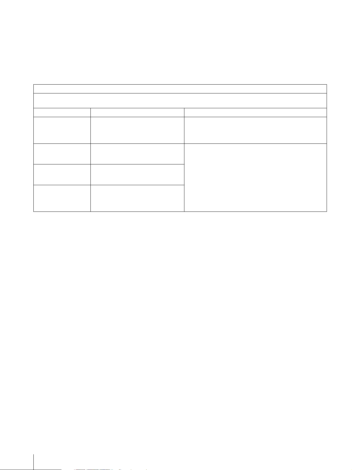
Guidance and manufacturer’s declaration-electromagnetic emissions
The UP-991AD/UP-971AD is intended for use in the electromagnetic environment specified below.
The customer or the user of the UP-991AD/UP-971AD should assure that it is used in such an environment.
Emission test Compliance Electromagnetic environment-guidance
RF emissions
CISPR 11
RF emissions
CISPR 11
Harmonic emissions
IEC 61000-3-2
Voltage fluctuations/
flicker emissions
IEC 61000-3-3
Warning
If the UP-991AD/UP-971AD should be used adjacent to or
stacked with other equipment, it should be observed to
Group 1
Class B
Class A
Complies
Warning
The use of accessories and cables other than those
specified, with the exception of replacement parts sold by
Sony Corporation, may result in increased emissions or
decreased immunity of the UP-991AD/UP-971AD.
The UP-991AD/UP-971AD uses RF energy only for its
internal function. Therefore, its RF emissions are very low
and are not likely to cause any interference in nearby
electronic equipment.
The UP-991AD/UP-971AD is suitable for use in all
establishments, including domestic establishments and
those directly connected to the public low-voltage power
supply network that supplies buildings used for domestic
purposes.
verify normal operation in the configuration in which it will be
used.
4
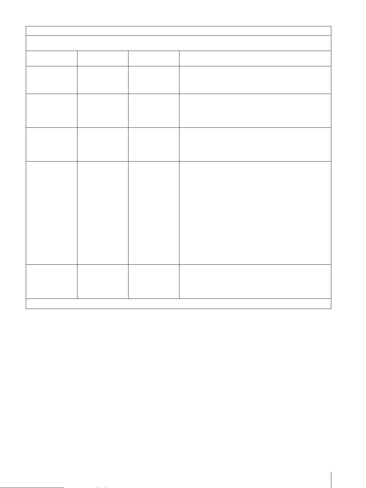
Guidance and manufacturer’s declaration - electromagnetic immunity
The UP-991AD/UP-971AD is intended for use in the electromagnetic environment specified below. The customer or the user
of the UP-991AD/UP-971AD should assure that it is used in such as environment.
Immunity test
Electrostatic
discharge (ESD)
IEC 60601 test
level
±6 kV contact
±8 kV air
Compliance level Electromagnetic environment-guidance
±6 kV contact
Floors should be wood, concrete or ceramic tile. If floors are
covered with synthetic material, the relative humidity should
±8 kV air
be at least 30 %.
IEC 61000-4-2
Electrical fast
transient/burst
±2 kV for power
supply lines
±2 kV for power
supply lines
Mains power quality should be that of a typical commercial or
hospital environment.
IEC 61000-4-4
Surge
IEC 61000-4-5
Voltage dips, short
interruptions and
voltage variations
on power supply
input lines
IEC 61000-4-11
Power frequency
(50/60Hz)
magnetic field
IEC 61000-4-8
NOTE: U
is the a.c. mains voltage prior to application of the test level.
T
±1 kV for input/
output lines
±1 kV differential
mode
±2 kV common
mode
< 5% U
T
(> 95% dip in U
for 0.5 cycle
40% UT
(60% dip in U
for 5 cycles
70% UT
(30% dip in U
for 25 cycles
< 5% U
T
(> 95% dip in U
for 5 sec
±1 kV for input/
output lines
±1 kV differential
mode
±2 kV common
mode
< 5% UT
(> 95% dip in U
)
T
for 0.5 cycle
40% UT
(60% dip in U
)
T
for 5 cycles
70% UT
(30% dip in U
)
T
for 25 cycles
< 5% U
(> 95% dip in U
)
T
for 5 sec
Mains power quality should be that of a typical commercial or
hospital environment.
Mains power quality should be that of a typical commercial or
hospital environment. If the user of the UP-991AD/UP-
)
T
971AD requires continued operation during power mains
interruptions, it is recommended that the UP-991AD/UP971AD be powered from an uninterruptible power supply or a
battery.
)
T
)
T
T
)
T
3 A/m 3 A/m Power frequency magnetic fields should be at least
characteristic of a typical location in a typical commercial or
hospital environment.
5
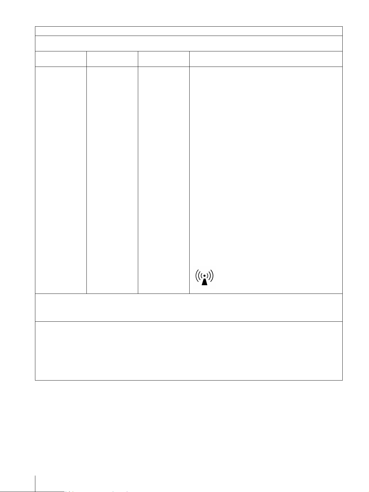
Guidance and manufacturer’s declaration - electromagnetic immunity
The UP-991AD/UP-971AD is intended for use in the electromagnetic environment specified below. The customer or the user
of the UP-991AD/UP-971AD should assure that it is used in such as environment.
Immunity test
IEC 60601 test
level
Compliance level Electromagnetic environment-guidance
Portable and mobile RF communications equipment should
be used no closer to any part of the UP-991AD/UP-971AD,
including cables, than the recommended separation distance
calculated from the equation appliance to the frequency of
the transmitter.
Recommended separation distance
Conducted RF
IEC 61000-4-6
Radiated RF
IEC 61000-4-3
NOTE 1: At 80 MHz and 800 MHz, the higher frequency range applies.
3 Vrms
150 kHz to 80 MHz
3 V/m
80 MHz to 2.5 GHz
3 Vrms
3 V/m
d = 1.2 √P
d = 1.2 √P 80 MHz to 800 MHz
d = 2.3 √P 800 MHz to 2.5 GHz
Where P is the maximum output power rating of the
transmitter in watts (W) according to the transmitter
manufacturer and d is the recommended separation distance
in meters (m).
Field strengths from fixed RF transmitters, as determined by
an electromagnetic site survey,
compliance level in each frequency range.
Interference may occur in the vicinity of equipment marked
with following symbol:
a
should be less than the
b
NOTE 2: These guidelines may not apply in all situations. Electromagnetic propagation is affected by absorption and
a Field strengths from fixed transmitters, such as base stations for radio (cellular/cordless) telephones and land mobile
radios, amateur radio, AM and FM radio broadcast and TV broadcast cannot be predicted theoretically with accuracy. To
assess the electromagnetic environment due to fixed RF transmitters, an electromagnetic site survey should be
considered. If the measured field strength in the location in which the UP-991AD/UP-971AD is used exceeds the
applicable RF compliance level above, the UP-991AD/UP-971AD should be observed to verify normal operation. If
abnormal performance is observed, additional measures may be necessary, such as reorienting or relocating the
UP-991AD/UP-971AD.
b Over the frequency range 150 kHz to 80 MHz, field strengths should be less than 3 V/m.
reflection from structures, objects and people.
6
Recommended separation distances between portable and mobile RF communications equipment and the
UP-991AD/UP-971AD
The UP-991AD/UP-971AD is intended for use in an electromagnetic environment in which radiated RF disturbances are
controlled. The customer or the user of the UP-991AD/UP-971AD can help prevent electromagnetic interference by
maintaining a minimum distance between portable and mobile RF communications equipment (Transmitters) and the
UP-991AD/UP-971AD as recommended below, according to the maximum output power of the communications equipment.
Rated maximum output power of transmitter
W
0.01 0.12 0.12 0.23
0.1 0.38 0.38 0.73
1 1.2 1.2 2.3
10 3.8 3.8 7.3
100 12 12 23
For transmitters rated a maximum output power not listed above, the recommended separation distance d in meters (m) can
be estimated using the equation applicable to the frequency of the transmitter, where P is the maximum output power rating
of the transmitter in watts (W) according to the transmitter manufacturer.
NOTE 1: At 80 MHz and 800 MHz, the separation distance for the higher frequency range applies.
Separation distance according to frequency of transmitter
150 kHz to 80 MHz
d = 1.2 √P
80 MHz to 800 MHz
m
800 MHz to 2.5 GHz
d = 1.2 √P
d = 2.3 √P
NOTE 2: These guidelines may not apply in all situations. Electromagnetic propagation is affected by absorption and
reflection from structures, objects and people.
Caution
When you dispose of the unit or accessories, you must
obey the laws in the relative area or country and the
regulations in the relative hospital.
Warning on power connection for
medical use
Please use the following power supply cord.
With connectors (plug or female) and cord types other
Warning on power connection
Use a proper power cord for your local power supply.
1. Use the approved Power Cord (3-core mains lead) /
Appliance Connector / Plug with earthing-contacts
that conforms to the safety regulations of each
country if applicable.
2. Use the Power Cord (3-core mains lead) / Appliance
Connector /Plug conforming to the proper ratings
(Voltage, Ampere).
If you have questions on the use of the above Power
Cord/Appliance Connector/Plug, please consult a
than those indicated in this table, use the power supply
cord that is approved for use in your area.
United States and Canada
Plug Type HOSPITAL GRADE*
Cord Type Min.Type SJT
Minimum Rating for Plug
and Appliance Couplers
Safety Approval UL Listed and CSA
*Note: Grounding reliability can only be achieved when the equipment is connected to an equivalent receptacle marked ‘Hospital Only’
or ‘Hospital Grade’.
Min.18 AWG
10A/125V
qualified service personnel.
For the customers in Europe
This product has been manufactured by or on behalf of
Sony Corporation, 1-7-1 Konan Minato-ku Tokyo, 1080075 Japan. Inquiries related to product compliance
based on European Union legislation shall be addressed
to the authorized representative, Sony Deutschland
GmbH, Hedelfinger Strasse 61, 70327 Stuttgart,
Germany.
For any service or guarantee matters, please refer to the
addresses provided in the separate service or guarantee
documents.
7
For the State of California, USA only
Perchlorate Material – special handling may apply, See
www.dtsc.ca.gov/hazardouswaste/perchlorate
Perchlorate Material: Lithium battery contains
perchlorate
For the customers in the U.S.A.
SONY LIMITED WARRANTY - Please visit http://
www.sony.com/psa/warranty for important
information and complete terms and conditions of
Sony’s limited warranty applicable to this product.
For the customers in Taiwan only
Disposal of Old Electrical & Electronic
Equipment (Applicable in Republic of India)
This symbol indicates that this product shall not be
treated as household waste and may not be dropped in
garbage bins. Product owners are advised to deposit
their product at the nearest collection point for the
recycling of electrical and electronic equipment.
Your co-operation shall facilitate proper disposal & help
prevent potential negative consequences/hazards to the
environment and human health, which could otherwise
be caused by inappropriate waste disposal including
improper handling, accidental breakage, damage
and/ or improper recycling of e-waste. The recycling
of materials will help to conserve natural resources.
For the customers in Canada
SONY LIMITED WARRANTY - Please visit http://
www.sonybiz.ca/solutions/Support.do for important
information and complete terms and conditions of
Sony’s limited warranty applicable to this product.
For the customers in Europe
Sony Professional Solutions Europe - Standard
Warranty and Exceptions on Standard Warranty.
Please visit http://www.pro.sony.eu/warranty
important information and complete terms and
conditions.
for
For the customers in Korea
SONY LIMITED WARRANTY - Please visit http://
bpeng.sony.co.kr/handler/BPAS-Start for important
information and complete terms and conditions of
Sony’s limited warranty applicable to this product.
For more detailed information about recycling of this
product, please contact your local civic office, your
household waste disposal service provider or the store
where you made the purchase. You may contact our
company’s toll free number in India for assistance.
This product complies with the “India E-waste Rule
2011”. The Ewaste Rules, 2011 is an Indian directive
aimed at reducing the harmful environmental impact of
waste electrical equipment by restricting the use of
known hazardous substances. As of 1st May 2012, new
electrical and electronic equipment introduced into the
market may no longer contain the following chemicals
or its specified maximum concentration levels: Lead,
Mercury, Hexavalent Chromium, Polybrominated
Biphenyls (PBB) or Polybrominated Diphenylethers
(PBDE) - in concentrations exceeding 0.1 weight % and
Cadmium - 0.01 weight %, except of exemptions set in
Schedule 2 of the aforesaid Rule.
8

Table of Contents
Getting Started
Overview ............................................................... 10
Location and Function of Parts and
Controls ................................................................11
UP-991AD ........................................................ 11
UP-971AD ........................................................ 13
Preparation
Loading Paper in the Unit .................................. 15
Connections
Connecting to video devices ................................ 17
Connecting to a computer ................................... 18
Connecting to the USB Connector ................... 18
Operation
Adjustments and Settings Using the Menu ....... 19
Menu structure and layer .................................. 20
Menu List ......................................................... 21
Basic Menu Operations .................................... 25
Registering Menu Settings ...............................26
Printing the Menu List ...................................... 27
Printing ................................................................. 28
Starting a Print Job of Video Images ................ 28
Printing digital images from a computer .......... 31
Adjusting print image quality ........................... 32
Storing Image Data on a USB Flash Drive (UP-
991AD only) .......................................................... 34
Storing Image Data on a USB Flash Drive ...... 34
Others
Precautions ...........................................................36
On Safety ..........................................................36
On the Printer Carriage .....................................36
On Installation ...................................................36
About the battery (UP-991AD only) ................36
Maintenance .........................................................37
Cleaning the Cabinet .........................................37
Cleaning the Thermal Head ..............................37
Cleaning the Platen Roller ................................38
Paper .....................................................................38
Paper You Can Use ...........................................38
Specifications ........................................................39
UP-991AD ........................................................39
UP-971AD ........................................................40
License ...................................................................42
Troubleshooting ....................................................43
Error Messages .....................................................44
Index ......................................................................45
9
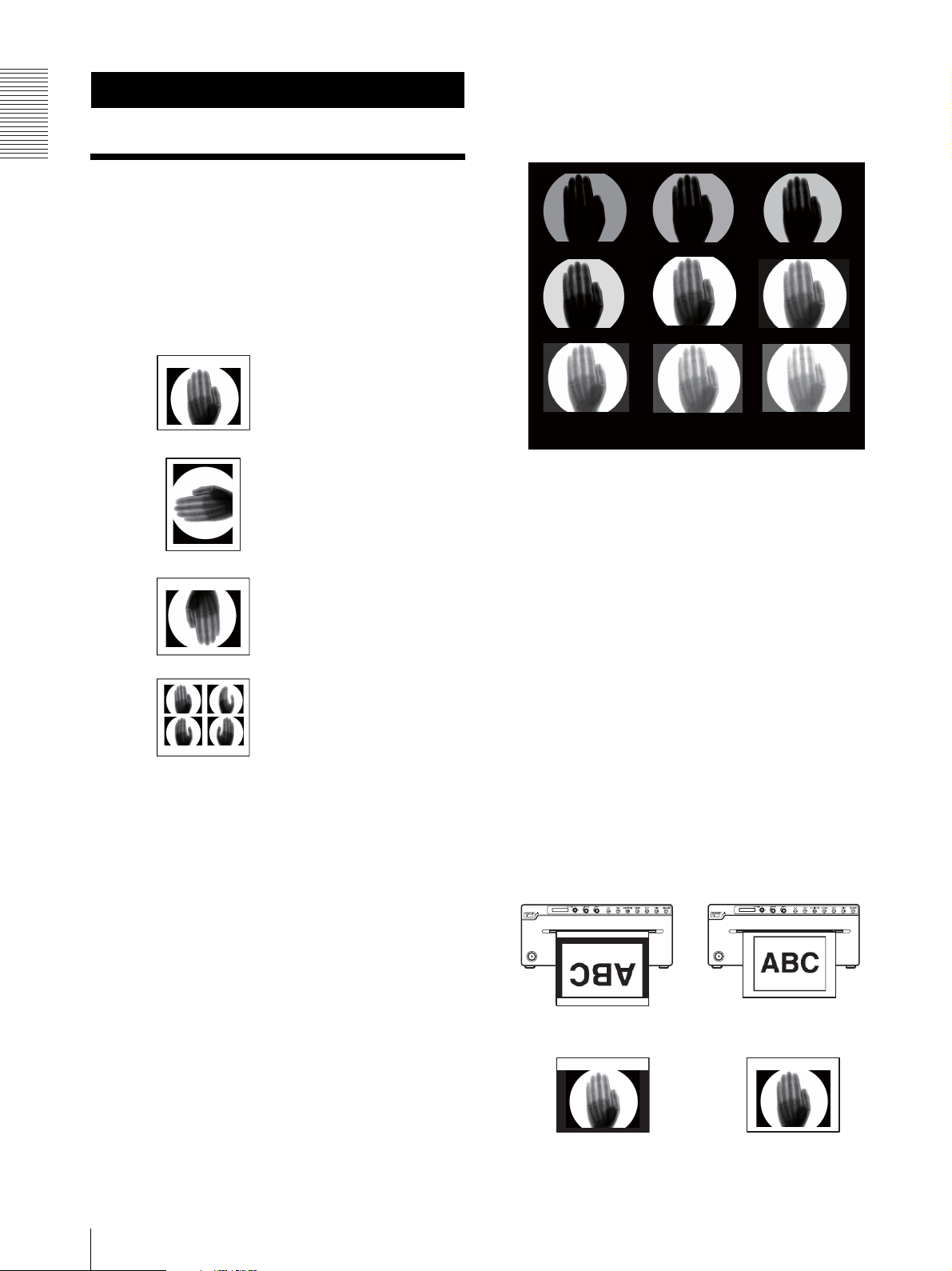
Easy picture quality adjustment function
Getting Started
By printing nine images as one page of which the
parameter is changed in picture quality adjustment
menu, you can select the most suitable adjustment.
Getting Started
Overview
Stable, high-quality printing
• Capable of high-resolution images of 12.8 dots/mm.
• 8-bit processing provides monochrome printing with
up to 256 shades of gradation.
BRIGHT=-12 BRIGHT=-8BRIGHT=-16
A variety of printing modes
Single-picture mode
Side mode
Reverse mode
Multi-picture mode
A change of settings makes available an even greater
number of print modes (see page 28).
Supports both video and digital input
• Prints captured images from color or monochrome
video signals in NTSC or PAL format.
• Prints the image from a computer which is compatible
with Hi-Speed USB (USB 2.0 compatible).
BRIGHT=0
BRIGHT=12 BRIGHT=16BRIGHT=8
CONTRAST=10 GAMMA=1 SHARP=2 TONE=8
BRIGHT=4BRIGHT=-4
Setting menu history function
Saves the last five menus that were used, allowing for
easy access to them next time.
Long-length picture printing
Supports 600 mm length digital printing.
Picture data to USB Flash Drive save function
(UP-991AD only)
Saves picture print data of both video and digital mode
to USB Flash Drive simultaneously when printing.
Auto cut function (UP-991AD only)
Automatically cuts the paper when printing completes.
Printing to film (UP-991AD only)
The UP-991AD can print on transparent film using UPT210BL (separately sold).
The difference between film printing and paper printing
In film printing, images are printed from the top.
Film print (UPT-210BL) Paper print (UPP-210HD,
UPP-210SE)
10
Film printing has a function to print a margin in black.
Overview
Backlight of the buttons
The unit can be operated in low light conditions. Buttons
that are functional for a particular setting will become
lit.
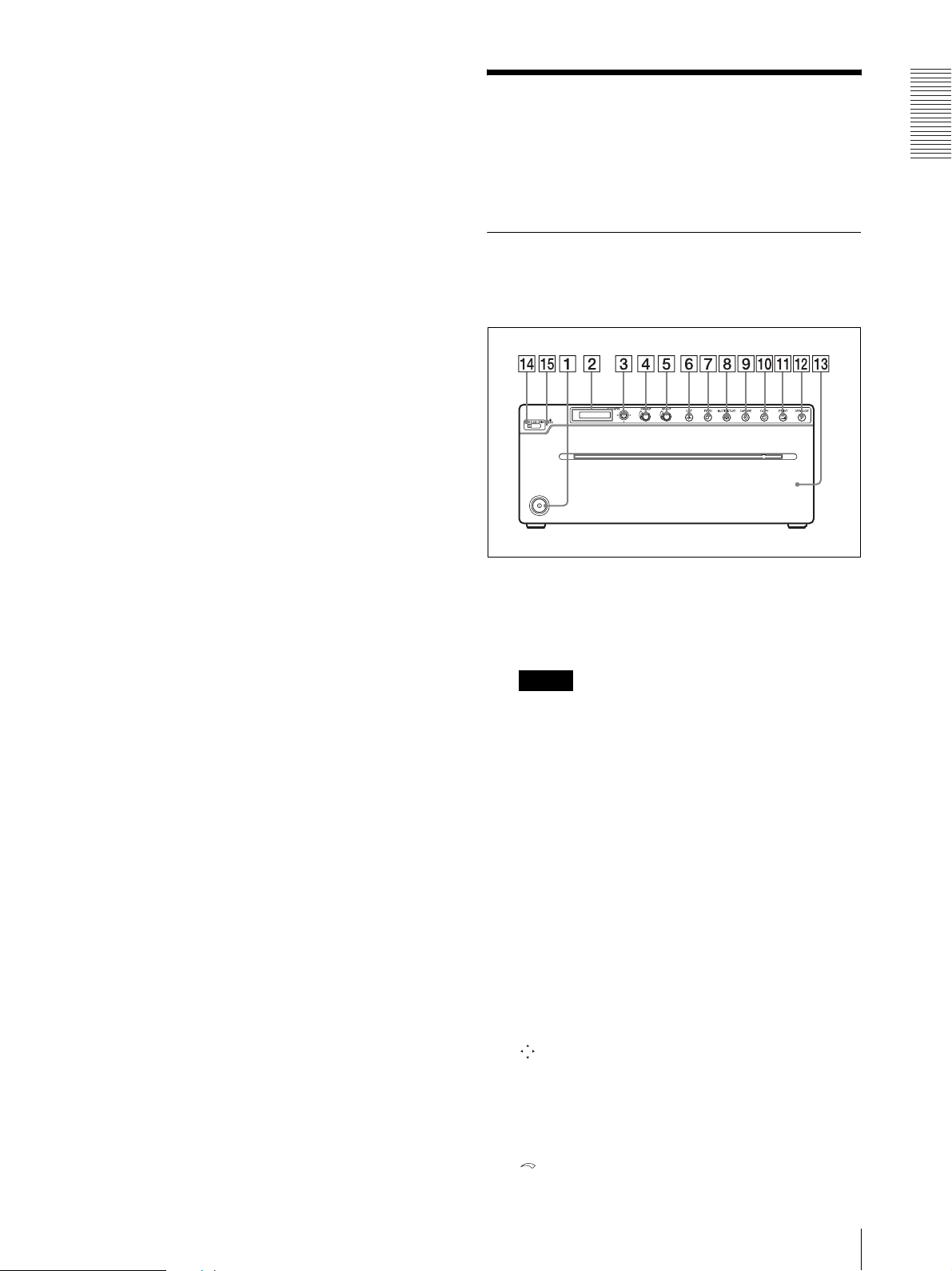
Location and Function of Parts and Controls
For more details, see the referenced page numbers
enclosed in parentheses ().
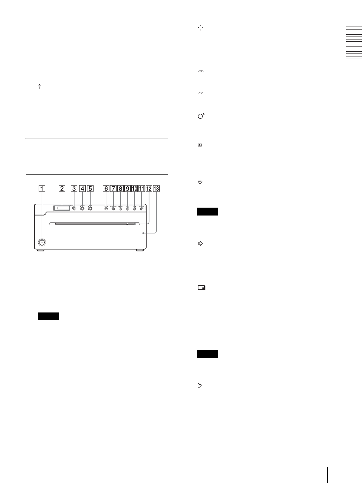
UP-991AD
Front Panel
A !Power on/off switch (page 15, 25, 28, 31, 37,
38)
Press to turn on the printer. The LCD display
backlight and button backlight turn on.
Getting Started
Note
When the unit is turned on/off, or the main power is
turned off and turned on again, turn on the unit after
about five seconds.
B Printer window display (LCD: liquid crystal
display) (page 25, 28, 31, 35)
The back light lights in green during normal unit
operation. Also, the kind of printing paper used is
shown on the right of the display when the paper
door opens or closes.
For detailed information on the paper, see “Loading
Paper in the Unit” on page 15 and “Paper” on page
38.
If an error occurs, a corresponding alarm message
is displayed.
During menu operations, menu items and settings
are displayed.
C Menu lever (page 20, 25, 37)
Navigate menus by tilting up, down, left or right.
Also, by pressing the center of the lever, you can
change the standby status to menu mode, or select
menu setting items.
D CONTRAST (contrast) dial (page 32)
Location and Function of Parts and Controls
11
Adjusts the contrast of printouts.
L OPEN/CLOSE button (page 15, 28, 37)
Press to open or close the paper door. While
E BRIGHT (brightness) dial (page 32)
printing, press to cancel the print job.
Adjusts the brightness of the printouts.
M Paper door
Getting Started
F CUT button (page 16, 28)
Press to cut the paper at the end of a print job using
the internal paper cutter.
While printing, press to cancel the print job.
Open to install or replace printing paper, and to
clean the thermal head and platen roller. Use the
OPEN/CLOSE button to open or close the paper
door.
G FEED button (page 16, 28, 28)
Hold down to feed paper. While printing, press to
cancel the print job.
H MULTI PICTURE (multi-picture) button
(page 29)
Toggles between the multi-picture mode and
single-picture mode.
Note
This function is available only when printing a
video image.
I CAPTURE button (page 29, 34)
In the multi-picture mode, press to store the print
image in the memory of the unit.
When “STR:CAPT” is selected in the “STR.KEY”
menu, image data captured from the video signals is
stored in the USB Flash Drive.
Note
This function is available only when printing a
video image.
J COPY button (page 30, 32)
Press to print a copy of the last printed image. Prints
only one paper regardless of the paper number set
in the “QTY” menu. This function is not available
in the multi-picture mode.
K PRINT button (page 28, 34)
In the multi-picture mode, images stored in the
memory of the unit (by the CAPTURE button) are
printed sequentially on a single paper.
In the single-picture mode, press to print the image
displayed on the monitor. When you press the
PRINT button, the displayed image is stored in the
memory of the unit and printed.
When “STR:PRNT” is selected in the “STR.KEY”
menu, the image is stored in a USB Flash Drive
after printing
Note
This function is available only when printing a
video image.
N USB Flash Drive terminal
Connect a USB Flash Drive to this terminal.
O USB Flash Drive access lamp
Displays USB Flash Drive access status, or verifies
any non-compatible USB devices.
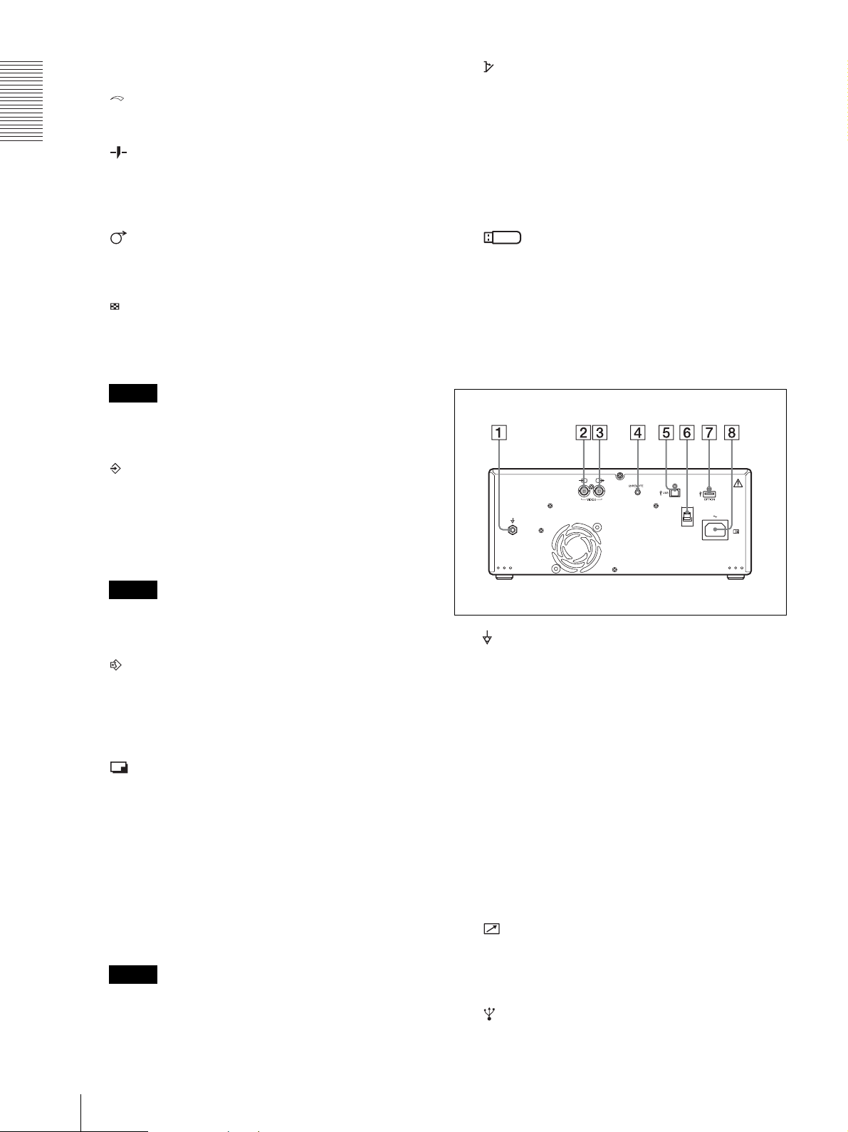
Rear Panel
A Equipotential terminal
Used to connect to the equipotential plug to bring
the various parts of a system to the same potential.
Refer to “Important safeguards/notices for use in
the medical environments” on page 3.
B t VIDEO IN (input) connector (BNC type)
Connect to the video output connector of video
equipment.
C T VIDEO OUT (output) connector (BNC type)
Connect to the video input connector of a monitor,
etc.
Outputs the video signal which is input from the
VIDEO IN terminal (Automatic termination is
provided).
D REMOTE connector (page 17, 30)
Connects the Remote commander RM-91 or Foot
switch FS-24 (separately sold) for controlling print
operation from a distance.
E USB connector (4-pin connector)
12
Location and Function of Parts and Controls
Use the USB cable to connect a computer with a
USB (USB 2.0 compliant) interface to this
connector.
F USB Cable Clamper
Holds and secures the USB cable connected to the
USB connector.
G OPTION terminal
Used for future expansion functions.
H - AC IN connector
Use the appropriate power cord for your local
power supply (not supplied).
C Menu lever (page 20, 25, 37)
Navigate menus by tilting up, down, left or right.
Also, by pressing the center of the lever, you can
change the standby status to menu mode, or select
the menu setting items.
Getting Started
D CONTRAST (contrast) dial (page 32)
Adjusts the contrast of printouts.
E BRIGHT (brightness) dial (page 32)
Adjusts the brightness of printouts.
F FEED button (page 16, 24, 28)
Hold down to feed paper. While printing, press to
cancel the print job.
UP-971AD
Front Panel
A !Power on/off switch (page 15, 25, 28, 31, 37,
38)
Press to turn on the printer. The LCD display
backlight and backlight of the button are lit when
the printer is on.
Note
When the unit is turned on/off, or the main power is
turned off and turned on again, turn on the unit after
about five seconds.
G MULTI PICTURE (multi-picture) button
(page 29)
Toggles between the multi-picture mode and
single-picture mode.
H CAPTURE button (page 29, 34)
In the multi-picture mode, press to store a print
image in the memory of the unit.
Note
This function is available only when printing a
video image.
I COPY button (page 30, 32)
Press to print a copy of the last printed image. Prints
only one paper regardless of the paper number set
in the “QTY” menu. This function is not available
in the multi-picture mode.
J PRINT button (page 28, 34)
In the multi-picture mode, images stored in the
memory of the unit (by the CAPTURE button) are
printed sequentially on a single paper.
In the single-picture mode, press to print the image
displayed on the monitor. When you press the
PRINT button, the displayed image is stored in the
memory of the unit and printed.
B Printer window display (LCD: liquid crystal
display) (page 25, 28, 31, 35)
The backlight lights in green during normal unit
operation. The printing paper type used is shown on
the right of the display when the paper door opens
or closes.
For detailed information on the paper, see “Loading
Paper in the Unit” on page 15 and “Paper” on page
38.
If an error occurs, a corresponding alarm message
is displayed.
During menu operations, menu items and settings
are displayed.
Note
This function is available only when printing a
video image.
K OPEN/CLOSE button (page 15, 28, 37)
Press to open or close the paper door. While
printing, press to cancel the print job.
L Paper Cutter
Cut the paper as each image is printed.
M Paper door
Location and Function of Parts and Controls
13

Open to install or replace printing paper, and to
clean the thermal head and platen roller. Use the
OPEN/CLOSE button to open or close the paper
door.
Refer to “Warning on power connection” on page 7
and “Warning on power connection for medical
use” on page 7.
Getting Started
Rear Panel
A Equipotential terminal
Used to connect to the equipotential plug to bring
the various parts of a system to the same potential.
See “Important safeguards/notices for use in the
medical environments” on page 3.
B t VIDEO IN (input) connector (BNC type)
Connect to the video output connector of video
equipment.
C T VIDEO OUT (output) connector (BNC type)
Connect to the video input connector of a monitor,
etc.
Outputs the video signal which is input from the
VIDEO IN terminal (Automatic termination is
provided).
D REMOTE connector (page 17)
Connects the Remote commander RM-91 or Foot
switch FS-24 (separately sold) for controlling print
operation from a distance.
E USB connector (4-pin connector)
Use the USB cable to connect a PC with a USB
(USB 2.0 compliant) interface to this connector.
F USB Cable Clamper
Holds and secures the USB cable connected to the
USB connector.
G OPTION terminal
Used for future expansion functions.
H - AC IN connector
Use the appropriate power cord for your local
power supply (not supplied).
14
Location and Function of Parts and Controls
 Loading...