

Page 1
Hybrid Graphic
Printer
2-659-569-12 (1)
Instructions for Use
_______________________________________ B
UP-990AD
UP-970AD
© 2006 Sony Corporation
Page 2
Owner’s Record
The model and serial numbers are located at the rear.
Record these numbers in the space provided below.
Refer to these numbers whenever you call upon your
Sony dealer regarding this product.
Model No. ____________________
Serial No. ____________________
WARNING
For the customers in Canada
This unit has been certified according to Standard CSA
C22.2 No.601.1.
For the customers in the U.S.A. and
Canada
Both the UP-990AD and the UP-970AD Hybrid
Graphic Printers are Non-Patient Equipment.
These units cannot be used in the vicinity of patients.
To reduce the risk of fire or electric shock, do
not expose this apparatus to rain or moisture.
To avoid electrical shock, do not open the
cabinet. Refer servicing to qualified personnel
only.
THIS APPARATUS MUST BE EARTHED.
To disconnect the main power, unplug the AC
IN connector.
This symbol indicates the equipotential
terminal which brings the various parts of a
system to the same potential.
For the customers in the U.S.A.
This equipment has been tested and found to comply
with the limits for a Class A digital device, pursuant to
Part 15 of the FCC Rules. These limits are designed to
provide reasonable protection against harmful
interference when the equipment is operated in a
commercial environment. This equipment generates,
uses, and can radiate radio frequency energy and, if not
installed and used in accordance with the instruction
manual, may cause harmful interference to radio
communications. Operation of this equipment in a
residential area is likely to cause harmful interference in
which case the user will be required to correct the
interference at his own expense.
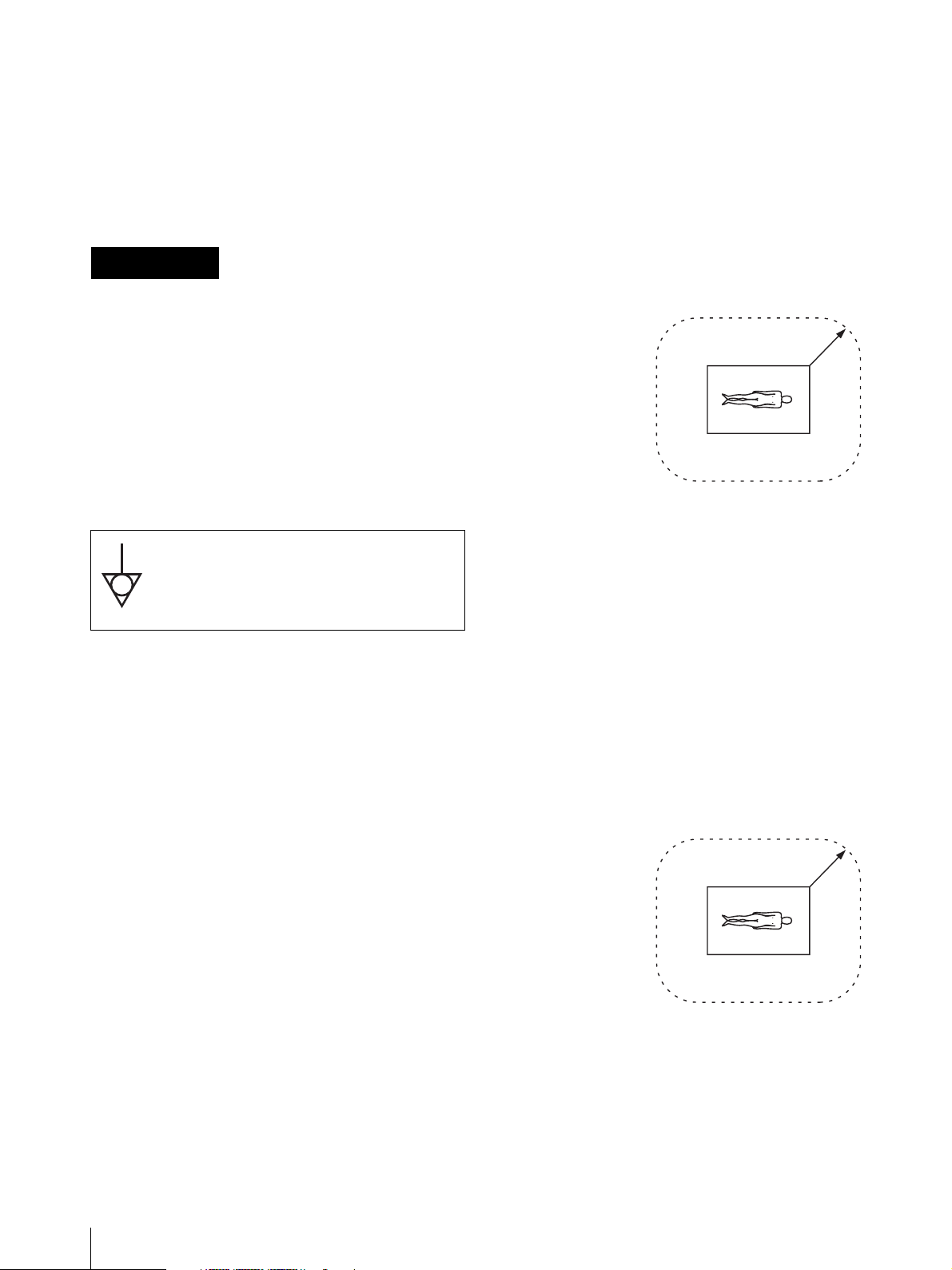
* Patient Vicinity
R1.83m
(6 feet)
When you use this product connected to 240V single
phase, be sure to connect this product to a center tapped
circuit.
Important safeguards/notices for use in
the medical environments
1. All the equipments connected to this unit shall be
certified according to Standard IEC60601-1,
IEC60950-1, IEC60065 or other IEC/ISO Standards
applicable to the equipments.
2. When this unit is used together with other equipment
in the patient area*, the equipment shall be either
powered by an isolation transformer or connected via
an additional protective earth terminal to system
ground unless it is certified according to Standard
IEC60601-1.
* Patient Area
R1.5m
You are cautioned that any changes or modifications not
expressly approved in this manual could void your
authority to operate this equipment.
All interface cables used to connect peripherals must be
shielded in order to comply with the limits for a digital
device pursuant to Subpart B of Part 15 of FCC Rules.
2
3. The leakage current could increase when connected
to other equipment.
Page 3
4. This equipment generates, uses, and can radiate radio
frequency energy. If it is not installed and used in
accordance with the instruction manual, it may cause
interference to other equipment. If this unit causes
interference (which can be determined by
unplugging the power cord from the unit), try these
measures: Relocate the unit with respect to the
susceptible equipment. Plug this unit and the
susceptible equipment into different branch circuit.
Consult your dealer. (According to standard
EN60601-1-2 and CISPR11, Class B, Group 1)
Caution
When you dispose of the unit or accessories, you must
obey the law in the relative area or country and the
regulation in the relative hospital.
Warning on power connection
Use a proper power cord for your local power supply.
1. Use the approved Power Cord (3-core mains lead) /
Appliance Connector / Plug with earthing-contacts
that conforms to the safety regulations of each
country if applicable.
2. Use the Power Cord (3-core mains lead) / Appliance
Connector /Plug conforming to the proper ratings
(Voltage, Ampere).
If you have questions on the use of the above Power
Cord/Appliance Connector/Plug, please consult a
qualified service personnel.
Warning on power connection for
medical use
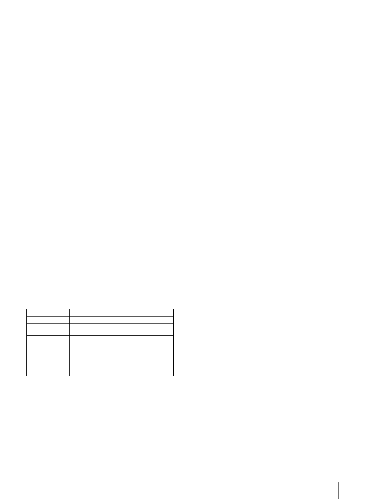
Please use the following power supply cord.
With connectors (plug or female) and cord types other
than those indicated in this table, use the power supply
cord that is approved for use in your area.
United States Canada
Plug Type HOSPITAL GRADE* HOSPITAL GRADE*
Female end E62405, E35708 LR53182, LL022442,
Cord type E159216, E35496
Minimum cord set
rating
Safety approval UL Listed CSA
*Note: Grounding reliability can only be achieved when the equipment
is connected to an equivalent receptacle marked ‘Hospital Only’ or
‘Hospital Grade’.
Min.Type SJT
Min.18 AWG
10A/125V 10A/125V
LL088408
LL112007-1, LL20262,
LL32121, LL84494
Min.Type SJT
Min.18AWG
3
Page 4

Table of Contents
Getting Started
Overview ................................................................ 5
Location and Function of Parts and Controls .... 5
UP-990AD ......................................................... 5
UP-970AD ......................................................... 7
Paper ....................................................................... 9
Paper You Can Use ............................................. 9
Loading Paper in the Unit .................................... 9
Analog Mode
Connections .......................................................... 12
Adjustments and Settings Using the Menu ....... 13
Menu Flow ....................................................... 14
Menu List ......................................................... 16
Basic Menu Operations .................................... 19
Registering Menu Settings ............................... 21
Printing the Menu List ..................................... 21
Printing ................................................................. 22
Starting a Print Job ........................................... 22
Selecting the Printing Direction and Size ........ 24
Adjusting the Contrast and Brightness ............. 25
Others
Precautions ...........................................................35
On Safety ..........................................................35
On the Printer Carriage .....................................35
On Installation ..................................................35
Maintenance .........................................................36
Cleaning the Cabinet ........................................36
Cleaning the Thermal Head ..............................36
Cleaning the Platen Roller ................................37
Specifications ........................................................37
UP-990AD ........................................................37
UP-970AD ........................................................38
Troubleshooting ....................................................40
Error Messages ....................................................41
Index ......................................................................42
Digital Mode
Connections .......................................................... 26
Connecting to the USB Connector ................... 26
Installing the Printer Driver .............................. 26
Adjustments and Settings Using the Menu ....... 26
Menu Flow ....................................................... 27
Menu List ......................................................... 29
Basic Menu Operations .................................... 31
Registering Menu Settings ............................... 32
Printing the Menu List ..................................... 32
Printing ................................................................. 33
Starting a Print Job ........................................... 33
Adjusting the Contrast and Brightness ............. 34
4
Page 5
Getting Started
Location and Function of Parts and Controls
Overview
Stable, high-quality printing
• Capable of high-resolution images of 12.8 dots/mm.
• 8-bit processing provides monochrome printing with
up to 256 shades of gradation.
A variety of printing modes
Single-picture mode
Side mode
Reverse mode
Multi-picture mode
For more details, see the referenced page numbers
enclosed in parentheses ().
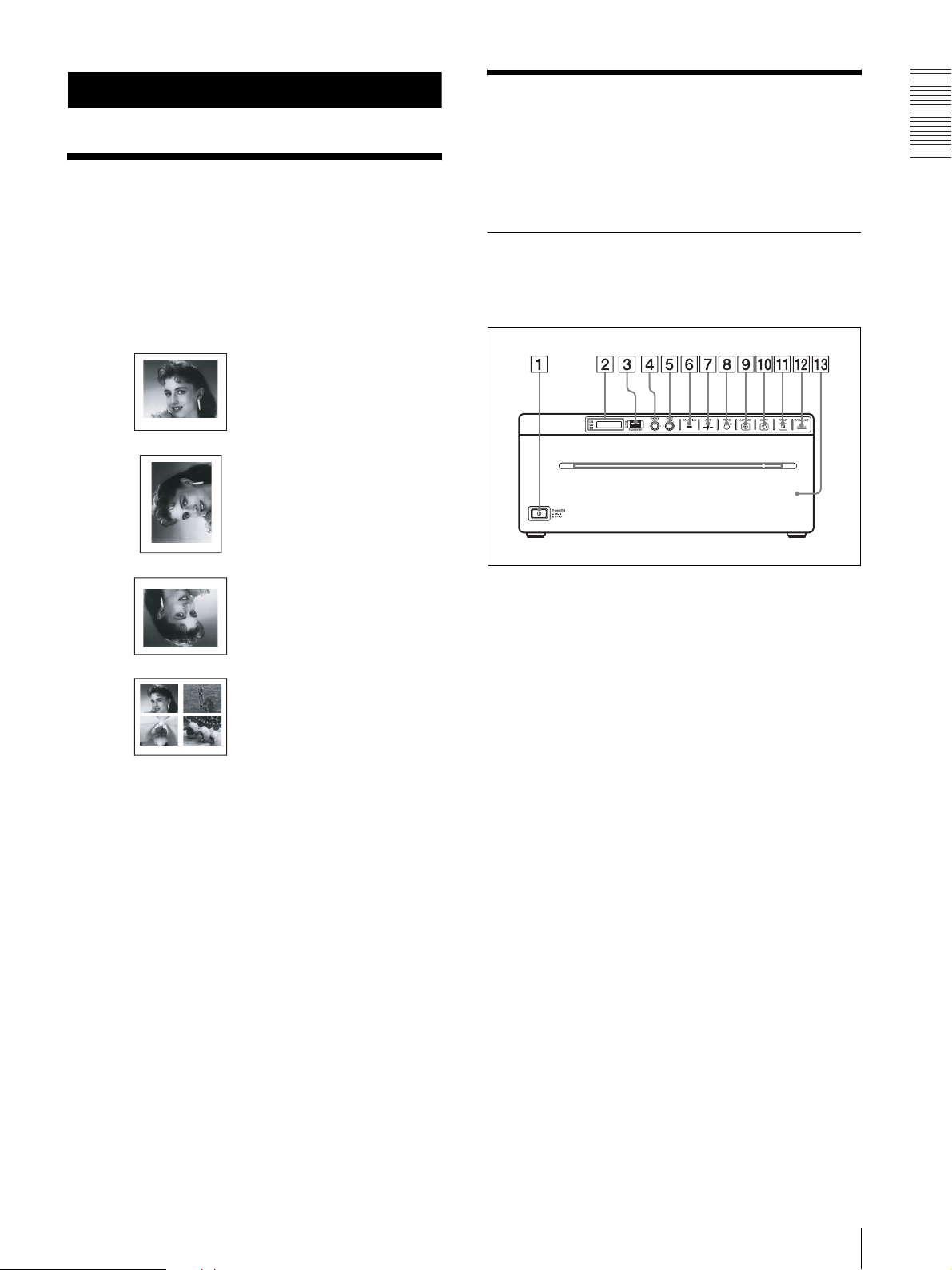
UP-990AD
Front Panel
A !Power ON/OFF Switch (page 9, 19, 22, 31, 33,
36)
Press to turn ON the printer. The LCD display
backlight as well as the CUT, FEED, COPY, and
PRINT buttons light.
* When set to digital mode, the PRINT button does not
light.
Getting Started
A change of settings makes available an even greater
number of print modes (see page 22).
Storing print modes
Store often used print modes as submenu values for
subsequent instant recall.
Supports both analog and digital input
• Prints NTSC and PAL color video signals as well as
EIA and CCIR monochrome video signals.
• Compatible with Hi-Speed USB (USB 2.0
compatible).
Auto cut function (UP-990AD only)
Automatically cuts the paper when printing completes.
Printing to film (UP-990AD only)
The UP-990AD can print on transparent film using UPT210BL (separately sold).
B Printer window display (LCD: liquid crystal
display) (page 14, 22, 27, 33)
The back light lights in green when the unit
operates normally. Also, in normal operation, the
paper currently selected is indicated by the pointer
on the LCD.
For detailed information on the paper, see
“Installing the Printer Driver” on page 26 and
“Paper currently selected” on page 22 and 33.
If an error occurs, a corresponding alarm message
is displayed.
During menu operations, menu items and settings
are displayed.
C Jog dial (page 20, 31, 36)
Used to make menu operations.
D CONTRAST (contrast) control (page 25)
Adjusts the contrast of the printouts.
E BRIGHT (brightness) control (page 25)
Adjusts the brightness of the printouts.
Overview / Location and Function of Parts and Controls
5
Page 6
F RECEIVING lamp
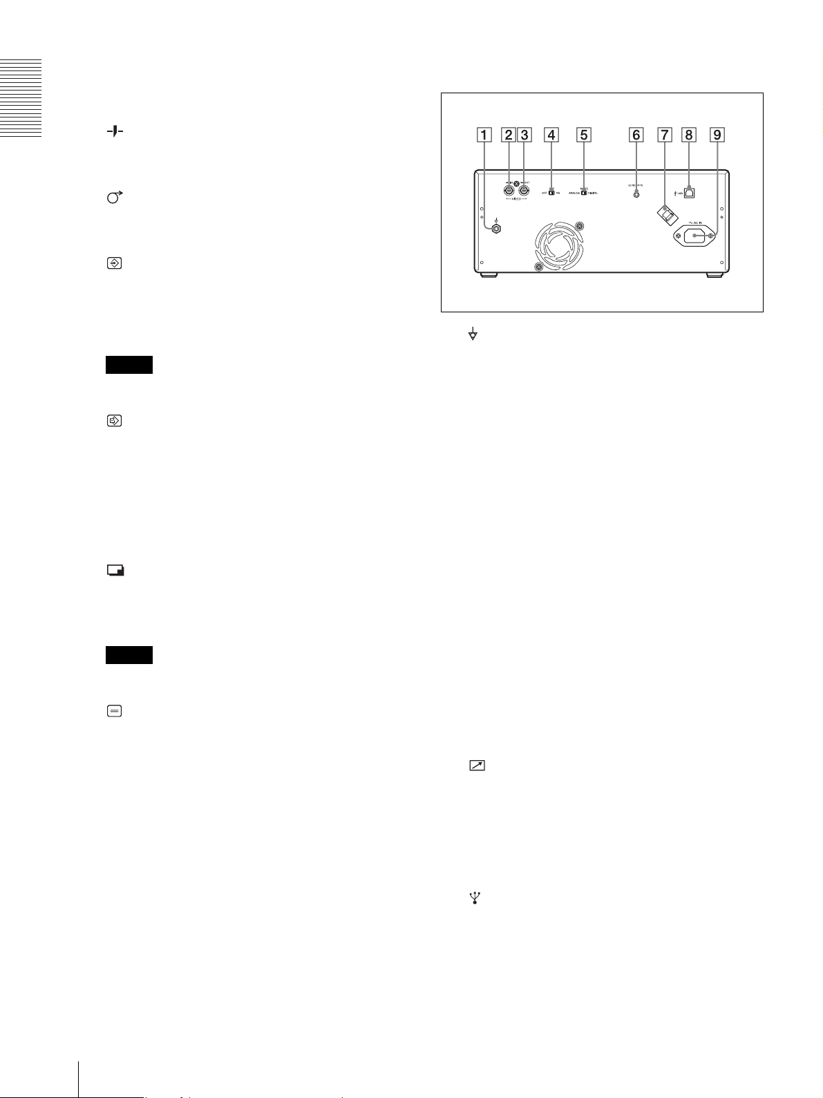
Rear Panel
Lights when the printer receives print data from a
PC.
G CUT button (page 22, 33)
Getting Started
Press to cut the completed print using the internal
paper cutter.
H FEED button (page 10, 22, 33)
Hold down to feed paper. While a print job is in
progress, press to cancel the print job.
I CAPTURE button (page 23)
In the multi-picture mode, press to store the print
image in memory.
This function is not available in the single-picture
mode.
A Equipotential terminal
Used to connect to the equipotential plug to bring
Note
This function is available only in the analog mode.
the various parts of a system to the same potential.
Refer to “Important safeguards/notices for use in
the medical environments” on page 2.
J COPY button (page 24)
In the multi-picture mode, use this button to print
images stored in memory (with the CAPTURE
button) side by side on a single sheet.
B t VIDEO IN (input) connector (BNC type)
Connect to the video output connector of the video
equipment.
In the single-picture mode, press to print another
copy of the last printed image.
In either mode, press once to print only the number
of prints set in the “QTY” menu.
C T VIDEO OUT (output) connector (BNC type)
Connect to the video input connector of the video
monitor. The output signal depends on the setting of
the “VIDEO” item of the menu.
K PRINT button
Prints the image currently displayed on the video
monitor. The image displayed when you press the
PRINT button is stored in memory.
D 75 Ω select switch
ON: When nothing is connected to the VIDEO
OUT connector, set the switch to this position.
OFF: When a video monitor or other video
Note
equipment is connected to the VIDEO OUT
connector, set the switch to this position.
This function is available only in the analog mode.
E ANALOG/DIGITAL switch
L OPEN/CLOSE button (page 10, 22, 33)
Press to open or close the paper door. While a print
Press to switch between analog and digital modes.
Turn the printer off before switching.
job is in progress, press to cancel the print job.
F REMOTE connector (page 12)
M Paper door
Open to install and replace printing paper, and to
Connects the RM-91 remote control unit for
controlling print operation from a distance.
clean the head and platen roller. Use the OPEN/
CLOSE button to open or close the paper door.
G USB Cable Clamper
Holds and secures the USB cable connected to the
USB port.
6
Location and Function of Parts and Controls
H USB connector (4-pin connector)
Use the supplied USB cable to connect a PC with a
USB (USB 2.0 compliant) interface to this
connector.
Page 7
I - AC IN connector
Use a proper power cord for your local power
supply (not supplied).
Refer to “Warning on power connection” on page 3
and “Warning on power connection for medical
use” on page 3.
UP-970AD
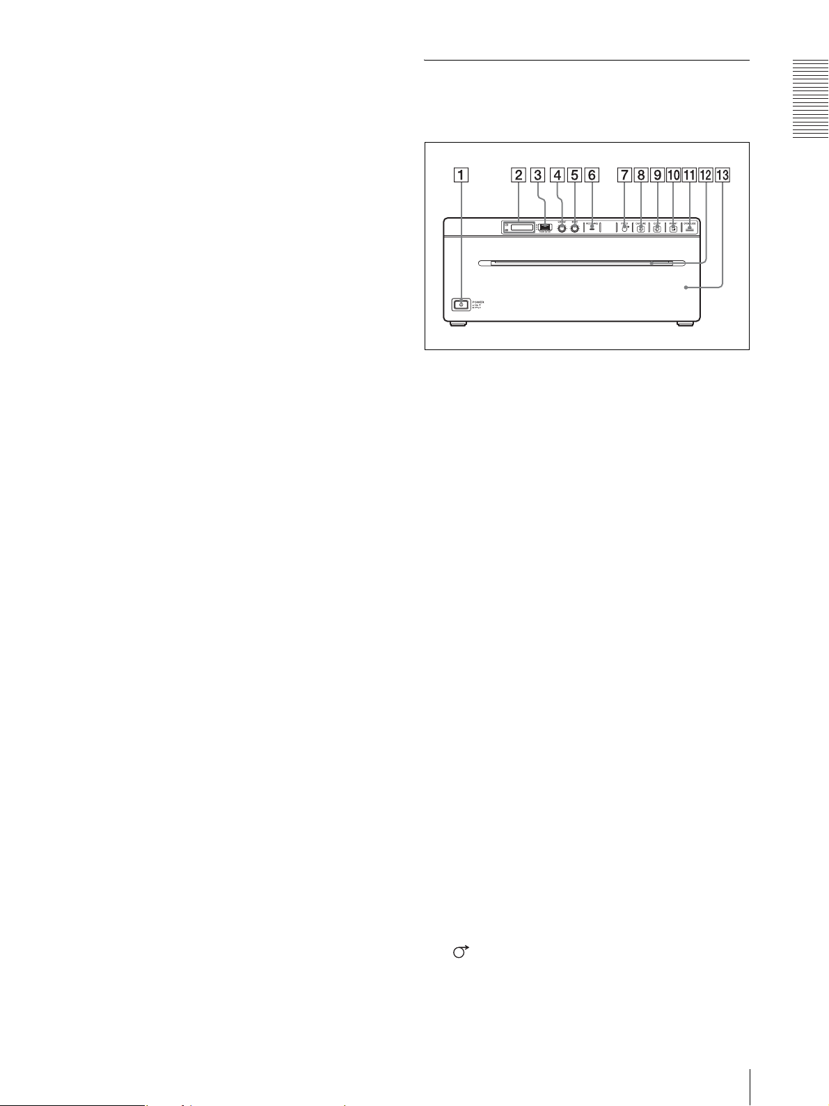
Front Panel
Getting Started
A !Power ON/OFF Switch (page 9, 19, 22, 31, 33,
36)
Press to turn ON the printer. The LCD display
backlight as well as the FEED, COPY, and PRINT
buttons light.
* When set to digital mode, the PRINT button does not
light.
B Printer window display (LCD: liquid crystal
display) (page 14, 22, 27, 33)
The back light lights in green when the unit
operates normally. Also, in normal operation, the
paper currently selected is indicated by the pointer
on the LCD.
For detailed information on the paper, see
“Installing the Printer Driver” on page 26 and
“Paper currently selected” on page 22 and 33.
If an error occurs, a corresponding alarm message
is displayed.
During menu operations, menu items and settings
are displayed.
C Jog dial (page 20, 31, 36)
Used to make menu operations.
D CONTRAST (contrast) control (page 25)
Adjusts the contrast of the printouts.
E BRIGHT (brightness) control (page 25)
Adjusts the brightness of the printouts.
F RECEIVING lamp
Lights when the printer receives print data from a
PC.
G FEED button (page 11, 22, 33)
Hold down to feed paper. While a print job is in
progress, press to cancel the print job.
Location and Function of Parts and Controls
7
Page 8
H CAPTURE button (page 23)
In the multi-picture mode, press to store the print
image in memory.
This function is not available in the single-picture
mode.
Getting Started
Note
This function is available only in the analog mode.
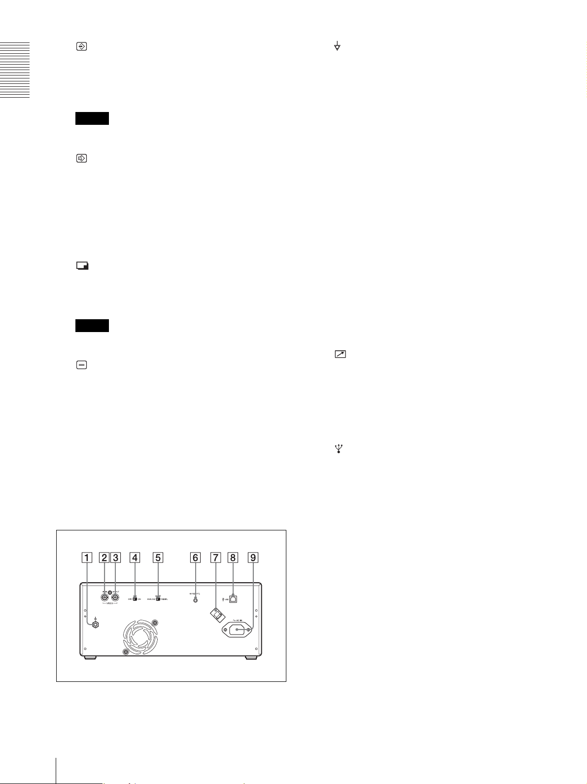
A Equipotential terminal
Used to connect to the equipotential plug to bring
the various parts of a system to the same potential.
Refer to “Important safeguards/notices for use in
the medical environments” on page 2.
B t VIDEO IN (input) connector (BNC type)
Connect to the video output connector of the video
equipment.
I COPY button (page 24)
In the multi-picture mode, use this button to print
images stored in memory (with the CAPTURE
button) side by side on a single sheet.
In the single-picture mode, press to print another
copy of the last printed image.
In either mode, press once to print only the number
of prints set in the “QTY” menu.
J PRINT button
Prints the image currently displayed on the video
monitor. The image displayed when you press the
PRINT button is stored in memory.
Note
This function is available only in the analog mode.
K OPEN/CLOSE button (page 10, 22, 33)
Press to open or close the paper door. While a print
job is in progress, press to cancel the print job.
L Paper Cutter
Cut the paper as each image is printed.
C T VIDEO OUT (output) connector (BNC type)
Connect to the video input connector of the video
monitor. The output signal depends on the setting of
the “VIDEO” item of the menu.
D 75 Ω select switch
ON: When nothing is connected to the VIDEO
OUT connector, set the switch to this position.
OFF: When a video monitor or other video
equipment is connected to the VIDEO OUT
connector, set the switch to this position.
E ANALOG/DIGITAL switch
Press to switch between analog and digital modes.
Turn the printer off before switching.
F REMOTE connector (page 12)
Connects the RM-91 remote control unit for
controlling print operation from a distance.
G USB Cable Clamper
Holds and secures the USB cable connected to the
USB port.
M Paper door
Open to install and replace printing paper, and to
clean the head and platen roller. Use the OPEN/
CLOSE button to open or close the paper door.
Rear Panel
H USB connector (4-pin connector)
Use the supplied USB cable to connect a PC with a
USB (USB 2.0 compliant) interface to this
connector.
I - AC IN connector
Use a proper power cord for your local power
supply (not supplied).
Refer to “Warning on power connection” on page 3
and “Warning on power connection for medical
use” on page 3.
8
Location and Function of Parts and Controls
Page 9
Paper
Loading Paper in the
Use only Sony UPP-210SE/210HD/UPT-210BL paper
designed for use with this unit. High print quality cannot
be guaranteed if any other paper is used with this unit,
and such paper could damage the unit.
Paper You Can Use
Print paper characteristics are as follows.
Print Characteristics Paper Type
TYPE I (Normal) UPP-210SE
TYPE II (High Density) UPP-210HD
TYPE III (Thermal film) UPT-210BL
Note
The UP-970AD model cannot use UPT-210BL.
Notes on storing and handling paper
Storing unused paper
• Store unused paper at a temperature below 30°C
(86°F) in a dry location that is not exposed to direct
sunlight.
• Do not store unused paper near volatile liquids or
allow the paper to contact any organic volatile liquid,
cellophane tape, or any compound of vinyl chloride.
Loading paper
• Handle the paper carefully when loading to avoid
touching the printing surface with your fingers.
Perspiration or oil from you hands could cause
pictures to blur.
• After removing the label from the leading edge of the
paper, pull the paper out 15~20 cm (about 6~8 in.)
before printing. Label adhesive remaining on the
paper could spoil a picture.
Storing printouts
• To prevent printouts from fading or changing color,
store them in a cool, dry location where the
temperature is not higher than 30°C (86°F).
• Store printouts in a polypropylene pouch or between
sheets of paper that contain no plastic.
• Do not store printouts where they will be exposed to
direct sunlight or high humidity.
• Do not store printouts near volatile liquids or allow the
prints to contact any organic volatile liquid,
cellophane tape, or any compound of vinyl chloride.
• To prevent fading, do not stack printouts on or under a
diazo copy sheet.
• To mount printouts on another sheet of paper, use
double-sides tape or a water base adhesive.
• Do not incinerate waste printer paper.
Unit
Notes
• Do not touch the print surface of thermal printing
paper when loading paper. The fingerprints,
perspiration and creases that may result will lower the
print quality.
• Use only UPP-210 series or UPT-210BL printing
paper (page 9).
• Make the menu settings required by the loaded paper
type (page 17, 30).
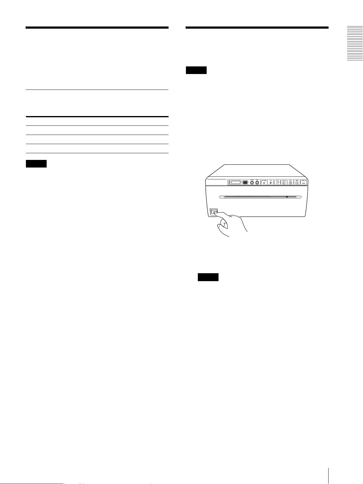
1
Press the power ON/OFF switch to turn on the
printer.
The LCD display shows the message “SONY UP990AD” for the UP-990AD and “SONY UP970AD” for the UP-970AD.
Notes
• The LCD display backlight lights in amber and
shows the message “EMPTY” when no printing
paper is loaded.
• The LCD display backlight lights in amber and
shows the message “DOOR” when the paper door
is open.
• When set to analog mode, the LCD display shows
the message “NOINP” if there is no video signal
input.
Getting Started
Paper / Loading Paper in the Unit
9
Page 10

2
Press the OPEN/CLOSE button to open the paper
door.
4
Insert the paper into the groove of the paper tray
and pull it out through the paper exit.
Note
Getting Started
Place the paper near the center of the groove of the
paper tray (inside of the guide). Note that paper
jams may occur if the paper is placed at the edge of
the groove of the paper tray.
3
Place the printing paper roll on the tray.
Using UPP-210SE/210HD
Remove label and pull
out 15 to 20 cm (about
6 to 8 inches).
Note
Pull out the printing paper to remove any slack and
possible creases.
Place the paper with the heat sensitive side facing
up. The printer will not print if the paper is
reversed.
Using UPT-210BL thermal film
* Cannot be used with the UP-970AD. Doing so may
cause a malfunction.
Correctly Inserted
Remove label and pull
out 15 to 20 cm (about
6 to 8 inches).
Incorrectly Inserted
Place the paper with the heat sensitive side facing
up. The printer will not print if the paper is
reversed.
5
Press the OPEN/CLOSE button to close the paper
door.
You can also push the paper door to close it.
6
Remove paper leading edge.
UP-990AD
After loading paper, press the FEED button to feed
out 15 to 20 cm (6 to 8 inches) of paper and press
the CUT button to remove it.
FEED Button
CUT Button
15 to 20 cm
10
Loading Paper in the Unit
Page 11
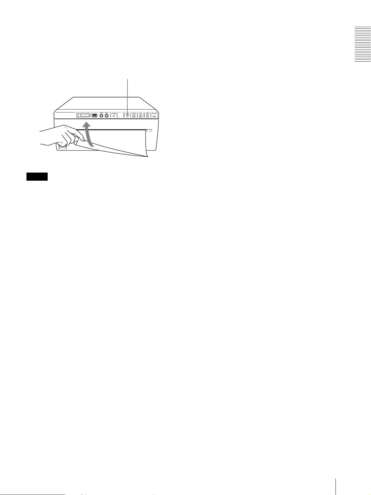
UP-970AD
After loading paper, press the FEED button to feed
out 15 to 20 cm (6 to 8 inches) of paper. Then use
the paper cutter to remove it. Be careful not to touch
the paper cutter when cutting the paper.
FEED Button
Note
To use UPT-210BL after printing with UPP-210SE/HD,
clean the head before printing as fine horizontal stripes
may otherwise appear on the paper.
Getting Started
Loading Paper in the Unit
11
Page 12

Analog Mode
Analog Mode
Connections
Notes
• Turn off the power to each device before making any
connections.
• Connect the AC power cord last.
• After completing connections, switch to the analog
mode before turning on the printer.
• The printer will not print images imported via the USB
terminal.
to
VIDEO
IN
Video equipment
to video output
connector
Connecting cable
(not supplied)
to VIDEO OUT
to REMOTE
Color/black and
white video monitor
Connecting cable
(BNC y BNC)
(not supplied)
to video input
connector
to AC IN
75 Ω select
a)
switch
RM-91 remote control unit
(not supplied)
a) Set the 75 Ω select switch as follows.
ON: When nothing is connected to the VIDEO OUT
connector, set the switch to this position.
OFF: When a video monitor or other video equipment is
connected to the VIDEO OUT connector, set the switch
to this position.
AC power
cord (not
supplied)
to wall outlet
12
Connections
Page 13

Adjustments and Settings Using the Menu
You can carry out adjustments and settings to meet your
requirements. Those settings and adjustments are
retained even if the unit is turned off.
You can set up the unit according to its intended
purpose, connected equipments or your individual
preferences.
You can store up to three settings as a set of user settings.
Analog Mode
Adjustments and Settings Using the Menu
13
Page 14

Analog Mode
Menu Flow
The contents displayed on the LCD changes in sequence
as you turn the jog dial as shown in the following menu
flow chart, and you can make the settings for each menu
item.
UP-990AD Menu Flow
(1): The single picture mode and multi-picture mode provide different functions. For details, see “Menu List”.
(2): The “SIZE.H”, “SIZE.V” settings and the signal system of the image to be captured determine the values you can set
with the Jog dial.
(3): The “SFT.H”, “SFT.V” settings and the signal system of the image to be captured determine the values you can set
with the Jog dial.
(4): The values you can set with the Jog dial in the analog mode are different from those in the digital mode.
14
Adjustments and Settings Using the Menu
Page 15

UP-970AD Menu Flow
Analog Mode
(1): The single picture mode and multi-picture mode provide different functions. For details, see “Menu List”.
(2): The “SCAN” settings and the signal system of the image to be captured determine the values you can set with the
Jog dial.
(3): The values you can set with the Jog dial in the analog mode are different from those in the digital mode.
Adjustments and Settings Using the Menu
15
Page 16

Analog Mode
Menu List
This section describes the menus displayed as you turn
the jog dial. The setting surrounded by
indicates the factory setting.
Item Function Settings
AGC To adjust the
input signal to the
optimum printing
level
a)
ASPCT
BEEP To turn operation
CLEAN To start head
CLEAR To delete images
.CUT
AT
(UP-990AD
only function)
b)
DIR
To select the
aspect ratio
tones ON and
OFF. Error tones
sound regardless
of setting.
cleaning
stored in memory.
To turn on and off
automatic cutting
of completed
prints.
To select whether
the top or bottom
of the screen is to
be printed first
AG:ON: Adjusts the input
signal to the optimum level,
when the printout image
appears too dark or too
light.
[AG:OFF]: Normally select
this setting.
BACK: Cancels the setting
change and returns to the
item selection column.
AS:1:1: Prints a video
signal with an aspect ratio
of 1:1.
[AS: 4:3]: Normally select
this setting.
BACK: Cancels the setting
change and returns to the
item selection column
BE: OFF: The operation
tone does not sound.
[BE: ON]: The operation
sounds.
BACK: Cancels the setting
change and returns to the
item selection column.
[CLN: OK]: Starts the head
cleaning. Be sure to use the
supplied cleaning sheet.
BACK: Cancels the head
cleaning and returns to the
item selection column.
[CLR: OK]: Deletes all
images stored in memory.
BACK: Cancels CLEAR
and returns to the item
selection column.
CT:OFF: Cuts the paper
when the CUT button is
pressed.
[CT:ON]: Cuts the paper
automatically.
BACK: Cancels the setting
change and returns to the
item selection column.
DI: REV: Starts to print in
the reverse direction (from
the top of the screen).
[DI: NOR]: Starts to print in
the normal direction (from
the bottom of the screen).
BACK: Cancels the setting
change and returns to the
item selection column.
Item Function Settings
FEED
(UP-990AD)
FEED
(UP-970AD)
FRAME To select the
GAMMA To select the tone
IMAGE To set the printout
INFO To select whether
To set the top and
bottom margin of
a print.
To select the
paper feed
method used after
printing.
color of the frame
between images
in multi-picture
mode.
of the printouts
(density
gradation)
to either positive
printout or
negative printout
or not the print
conditions (such
as contrast,
bright, gammas
and sharpness
information) are
printed under the
image
[FE: 0]to FE:15: Sets the
margin to one of 16 steps
from 0 to 15. An increase of
one step increases the top
and bottom margin by 5
mm. The top and bottom
margin can be increased to
75 mm. The “0” setting is
the default value, which
still provides a narrow
margin between two
images.
BACK: Cancels the setting
change and returns to the
item selection column.
[FE: ON]: Increases the
margin between prints.
FE:OFF: Sets when
reducing the margin or
when printing multiple
images on the same sheet.
This reduces the margin
between images allowing
you to print more images
per roll. However, with this
setting, the FEED button
must be pressed before
cutting the paper.
BACK: Cancels the setting
change and returns to the
item selection column.
FR:BLK: Sets the frame
color to black.
[FR:WHT]: Sets the frame
color to white.
BACK: Cancels the setting
change and returns to the
item selection column.
GA:3: TONE 3 Hard
gradation
GA:2: TONE 2 Soft
[GA:1]: TONE 1 Standard
gradation
BACK: Cancels the setting
change and returns to the
item selection column.
IM:NEG: Makes negative
printouts.
[IM:POS]: Makes normal
printouts.
BACK: Cancels the setting
change and returns to the
item selection column.
IF:ON: Prints the
information.
[IF:OFF]: Does not print the
information.
BACK: Cancels the setting
change and returns to the
item selection column.
16
Adjustments and Settings Using the Menu
Page 17

Item Function Settings
INIT To return
(initialize) all
menu items to
their factory
defaults.
INTRT To select
operation
performed when
printing of the
current image is
interrupted.
LOAD To load the
registered settings
MEDIA To select the type
of paper
[INI:OK]: Returns all
settings to their factory
defaults.
BACK: Cancels
initialization and returns to
the item selection column.
In single picture mode
IN:ON: Stops printing
when the PRINT button is
pressed during printing and
starts printing the image
captured at the instant you
pressed the PRINT button.
[IN:OFF]: Printing does not
stop even if the PRINT
button is pressed during
printing. When printing of
the current image ends, the
unit prints the image
captured at the instant you
pressed the PRINT button.
In multi-picture mode
IN:ON: Stops printing
when the CAPTURE button
is pressed during printing.
The image captured at the
instant you pressed the
CAPTURE button is
inserted at the location
indicated by flashing.
[IN:OFF]: Disables the
interruption of printing or
image capture, even if the
CAPTURE button is
pressed during printing.
BACK: Cancels the setting
change and returns to the
item selection column.
LO:3: Loads the “SA:3”
settings registered using the
“SAVE” menu item.
LO:2: Loads the “SA:2”
settings registered using the
“SAVE” menu item.
[LO:1]: Loads the “SA:1”
settings registered using the
“SAVE” menu item
BACK: Cancels the setting
change and returns to the
item selection column.
ME:HG: Uses UPP-210SE.
[ME: HD]: Uses UPP210HD.
ME:BL: Uses UPT-210BL.
However, the UP-970AD
model cannot use UPT210BL.
BACK: Cancels the setting
change and returns to the
item selection column.
Item Function Settings
MEMRY To select the
memory mode
MENU To print the menu
MIROR To print mirror
MULTI To specify the
PAG E
(These menu
settings are
not available
when “MU:2”
to “MU:6” is
selected in
“MULTI”.)
A.PRNT To turn on and off
settings currently
selected
images.
number of images
to be printed on
one sheet of the
printout
Each time you
press the PRINT
button, the image
is stored in
memory. Up to 6
images can be
stored.
You can select the
desired image
from 6 kinds of
images stored in
memory and
make a printout.
automatic
printing in multipicture mode.
ME:FLD: When printing
fast-moving images (such
as a ball being thrown), the
printout may be blue. If this
happens, select this setting.
[ME:FRM]: Normally select
this setting.
BACK: Cancels the setting
change and returns to the
item selection column.
[ME:OK]: Prints the menu
list currently set.
BACK: Cancels printing
and goes back to its item
column.
MI:ON: Prints mirror
images.
[MI:OFF]: Prints normal
images not mirror images.
BACK: Cancels the setting
change and returns to the
item selection column.
MU:6: Prints six images on
one sheet of the printout
(six reduced images).
MU:4: Prints four images
on one sheet of the printout
(four reduced images).
MU:2: Prints two images
on one sheet of the printout
(two reduced images).
[MU:1]: Prints one full-size
image.
BACK: Cancels the setting
change and returns to the
item selection column.
[PG:1] to PG:6: Prints by
selecting the desired ONE
image from among images
1 to 6 and pressing the
COPY button.
BACK: Cancels the setting
change and returns to the
item selection column.
A.P:ON: Automatically
prints when all the images
of the selected multi-picture
mode are captured without
the need to press the COPY
button.
[A.P:OFF]: Prints images
when the COPY button is
pressed.
BACK: Cancels the setting
change and returns to the
item selection column.
Analog Mode
Adjustments and Settings Using the Menu
17
Page 18

Analog Mode
Item Function Settings
QTY To set the print
quantity
[QT:1] to QT:10: Prints
from one to ten copies of
the same image.
BACK: Cancels the setting
change and returns to the
item selection column.
SAVE To register up to
three kinds of
settings
SA:3: Registers the menu
settings as No.3.
SA:2: Registers the menu
settings as No.2.
[SA:1]: Registers the menu
settings as No.1.
BACK: Cancels the setting
change and returns to the
item selection column.
SCAN
(for the UP970AD only)
To set the size of
the captured
image.
SC:WD2: Maximum size
[SC:WD1]: Medium size
SC:NOR: Minimum size
BACK: Cancels the setting
change and returns to the
item selection column.
SFT.H
(UP-990AD)
To specify the
horizontal
position of the
image to be
printed.
[S.H:192]: Moves the print
area horizontally relative to
the captured image. The
numeric value displayed by
turning the jog dial depends
on the “SIZE.H” setting
and the signal system.
BACK: Cancels the setting
change and returns to the
item selection column.
SFT.H
(UP-970AD)
To specify the
position in the
horizontal
direction of the
image to be
printed.
[H:0]: Adjusts the
horizontal position. The
numeric value displayed by
turning the jog dial depends
on the signal system of the
image to be captured and
the range setting of images
captured with “SCAN”.
BACK: Cancels the setting
change and returns to the
item selection column.
SFT.V
(UP-990AD)
To specify the
vertical position
of the image to be
printed.
[S.V:20]: NTSC signal
input.
[S.V:28]: PAL signal input.
Adjusts the vertical position
of the printing area relative
to the captured image. The
numeric value displayed by
turning the jog dial depends
on the “SIZE.V” setting
and the signal system.
BACK: Cancels the setting
change and returns to the
item selection column.
Item Function Settings
SFT.V
(UP-970AD)
To specify the
position in the
vertical direction
of the image to be
printed.
[V:0]: Adjusts the vertical
position. The numeric value
displayed by turning the jog
dial depends on the signal
system of the image to be
captured and the range
setting of images captured
with “SCAN”.
BACK: Cancels the setting
change and returns to the
item selection column.
SHARP To adjust the
sharpness of the
printout
[SH:0] to SH:14:You can set
the sharpness to any of 15
steps from 0 to 14. A higher
number indicates greater
sharpness. A setting of “0”
indicates that the function is
off, which is also the
default value.
BACK: Cancels the setting
change and returns to the
item selection column.
SIDE
c)
To select the
direction in which
the image is to be
printed
S:SIDE: Prints the image
rotated by 90 degrees
counterclockwise.
[S:STD]: Prints the image in
the same direction as that
displayed on the monitor.
BACK: Cancels the setting
change and returns to the
item selection column.
SIZE.H
(for the UP990AD only)
To set the number
of dots in the
horizontal
direction of the
printed image.
[H: 1202]: NTSC signal
input.
[H: 1202]: PAL signal input.
Changing the value
increases or decreases the
number of horizontal dots
to the right of the fixed left
edge of the image.
BACK: Cancels the setting
change and returns to the
item selection column.
SIZE.V
(for the UP990AD only)
To set the number
of dots in the
vertical direction
of the printed
image.
[V:480]: NTSC signal input.
[V:574]: PAL signal input.
Adjusts the vertical position
of the bottom edge with
respect to the fixed top edge
of the image.
BACK: Cancels the setting
change and returns to the
item selection column.
TRAP To select the
input signal to be
printed
TR:ON: Prints the color
signal.
[TR:OFF]: Prints the black
and white signal.
BACK: Cancels the setting
change and returns to the
item selection column.
18
Adjustments and Settings Using the Menu
Page 19

Item Function Settings
I
VIDEO To select the
video signal
output from the
VIDEO OUT
connector on the
rear panel
BACK To exit menu
mode
VI:EE: Outputs the signal
after it is processed by the
printer.
[VI:THR]: Outputs the signal
directly without processing.
BACK: Cancels the setting
change and returns to the
item selection column.
Select this item and press
the jog dial to exit the menu
mode.
c) The print direction of the images printed is as follows.
mage displayed on the monitor
Analog Mode
a) The aspect ratio is as follows.
When AS:4:3 is selected
When AS:1:1 is selected
b) The printing direction is as follows.
When DI:NOR is selected When DI: REV is selected
Printouts
When S:STD is selected. When S:SIDE is selected
Basic Menu Operations
This section describes the basic menu operation which
are common to each menu, taking “How to set the
printing direction” as an example.
1
Press the power ON/OFF switch to ON to turn the
unit on.
The back light on the LCD lights in green.
LCD
Adjustments and Settings Using the Menu
19
Page 20

Analog Mode
2
Confirm that “READY” is displayed on the LCD,
and press the jog dial.
The unit enters the menu mode.
When you perform a menu operation for the first
time after you purchase the unit, the top item of the
“AGC” menu is displayed.
If you have performed a menu operation already,
the item that you set last is displayed.
3
Display “DIR” by turning the jog dial up or down.
5
Display “DI:REV” in the LCD by turning the jog
dial up or down, and then press the jog dial.
“DI:REV” is registered as the printing direction.
“DIR” reappears on the LCD.
4
Press the jog dial.
The unit enters the mode in which you can select
the printing direction.
“DI:NOR,” which is the factory setting, is
displayed on the LCD. “DI:NOR” is the currently
selected setting.
In this menu operation, you will change the setting
to “DI:REV.”
Note
If about 20 seconds elapse without making any
menu operation after you have displayed the menu
item or setting, the display returns to “READY” on
the LCD and the unit exits the menu mode. In such
a case, the setting of “DIR” is not changed.
To cancel the setting
1
Display “BACK” by turning the jog dial in step 5.
2
Press the jog dial.
The display on the LCD returns to “DIR.”
To continue menu operations
Make settings by repeating steps 3 to 5.
To end the menu operation
1
Display “BACK” by turning the jog dial after
performing the operation of step 5.
2
Press the jog dial.
The unit exits the menu mode.
Menu lock function
If the message “LOCK” is displayed and you hear the
alarm sound when you press the jog dial, the jog dial is
disabled because the menu operation function is locked.
If you want to perform a menu operation, contact the
nearest authorized dealer.
20
Adjustments and Settings Using the Menu
Page 21

Registering Menu Settings
You can store up to three sets of settings made using the
menu, and you can load the desired setting when needed.
The unit retains these settings even if you turn off the
power.
Note
When you use the unit for the first time after you
purchase it, factory settings are registered in all three of
the stored selections.
1
Load the settings of “LO:1” following the
procedure for loading the desired settings.
2
Change the loaded settings as required.
3
Select “SA:2” following procedure for registering
the settings.
4
Press the jog dial.
The settings, changed in step 2, are registered as
“SA:2” (No.2).
Analog Mode
Registering new settings
1
Make all of the required settings.
2
Display “SAVE” by turning the jog dial, and then
press the jog dial.
3
Display the desired number by turning the jog dial,
and then press the jog dial, again.
The settings made in step 1 are registered in the
number selected in step 3.
Loading the desired settings
You can load the desired settings and make printouts
with the loaded settings.
1
Confirm that “READY” is displayed on the LCD,
and press the jog dial.
2
Display “LOAD” by turning the jog dial, and then
press the jog dial again.
3
Display the number corresponding to the desired
settings, and then press the jog dial.
Settings corresponding to the number selected in
step 3 are loaded.
Printing the Menu List
You can make a printout of the current menu settings.
1
Press the jog dial.
The menu item you changed last is displayed.
2
Display “MENU” by turning the jog dial, and then
press the jog dial.
3
Display “ME:OK” by turning the jog dial and then
press the jog dial.
The unit starts printing the current menu settings.
MENU is displayed on the LCD.
4
Display “BACK” by turning the jog dial, and then
press the jog dial.
The unit returns to the normal printing mode.
When you change the loaded settings
The unit operates according to the changed settings. In
this case, the unit operates according to these settings
until you load another set of settings, even if you turn off
the unit. When you load another group of settings, the
settings loaded previously are cleared.
To retain previously loaded settings
Example: Settings registered as “SA:1” are loaded and
settings are to be changed. To retain the original settings
of “SA:1” and to register the new settings as “SA:2,”
proceed as follows.
Adjustments and Settings Using the Menu
21
Page 22

Analog Mode
Printing
Before Starting a Print Job
Always check the following points:
• Unit connected correctly? (page 12)
• Paper loaded correctly? (page 9)
• Menu settings and menu adjustments done correctly?
(page 13)
• Video source being input?
When the unit stops printing during printing
When printing almost black images continuously, the
thermal head protection circuit may shut down the unit
to prevent the thermal head from overheating. In such a
case, the message “COOL” is displayed on the LCD.
Leave the unit until the head cools down and this
message disappears.
To cancel a print job in progress
To cancel a print job in progress, press the OPEN/
CLOSE button, FEED button or CUT button.
Starting a Print Job
You can set up the printing direction, image size, all
sorts of settings for printing, using the menu. This
section describes operations after completing all sorts of
settings using the menu.
1
Press the power ON/OFF switch to turn the unit on.
The back light on the LCD lights in green, and
“READY” is displayed on the LCD.
LCD
2
Start the video source.
This operation is done using the controls of the
video equipment which you are using as a source.
To feed paper
To feed paper, press the FEED button. The unit will
continue to feed paper as long as you hold down the
FEED button. Do not attempt to pull paper out of the
unit with your hand.
Paper currently selected
You can confirm the paper currently selected on the
LCD. The pointer points to the paper currently selected.
In the following figure, the currently selected paper is
the UPP-210SE paper.
UP-990AD
Indicates the UPP-210SE
Indicates the UPP-210HD
Indicates the UPT-210BL
3
Press the PRINT button when the image you want
to print is on the video monitor.
The image displayed at the instant you press the
PRINT button is captured into memory and is
printed out immediately. Up to 6 captured images
are stored in memory. When captured image
exceeds 6, the oldest data is overwritten with the
latest one in sequence.
When the message is displayed on the LCD
If a problem occurs, the back light on the LCD lights in
umber and the error message stating the problem is
displayed on the LCD.
Message Cause and remedy
EMPTY Paper is not loaded. Load paper.
DOOR The paper door is open. Close the
paper door.
NOINP There is no video signal input. Input a
22
Printing
video signal.
Note
If “CT:ON” is selected in the “AT.CUT” menu,
quickly remove the prints that have been cut.
Otherwise, the cut prints may block the paper exit
and cause a paper jam to occur.
UP-970AD
Indicates the UPP-210SE
Indicates the UPP-210HD
Page 23

If the printout image is blurred
A rapidly moving image may be blurred when printed.
Should this occur, make a printout with “ME:FLD”
selected in the “MEMRY” menu item.
Printing images stored in memory
Each time you press the PRINT button, the image is
stored in memory. After 6 images have been stored, the
oldest image data is overwritten with the newest
captured image in sequence. There are always 6 images
stored in memory. You can load the desired one from
among them and print it using the menu.
1
Select “PAGE” from among the menu items.
For detailed information on menu operation, see
“Basic Menu Operations” on page 19.
2
Press the jog dial.
“PG:1” is displayed on the LCD, and the image
printed last is displayed on the monitor.
3
Display the image that you want to print by turning
the jog dial up or down.
4
Press the CAPTURE button again to capture any
displayed image.
When the “A.PRINT” menu is ON, printing starts
automatically as soon as the number of images
specified by “MU:(2/4/6)” is captured. When the
menu is OFF, press the COPY button to start
printing.
Capturing two images (“MU:2 selected in
“MULTI”)
Image captured
in step 3
Printing direction
Capturing four images (“MU:4 selected in
“MULTI”)
Image captured
in step 4
Analog Mode
4
Press the jog dial.
The image selected in step 3 is loaded.
5
Press the COPY button.
The image selected in step 3 is printed.
Printing two, four or six images on one
sheet
Use “MULTI” item of the menu to capture and print two
to six different images on one sheet.
1
Set “MULTI” item of the menu to “MU:2” “MU:6”, according to the number of images you
want to print on one sheet.
2
Turn the Jog dial to display the BACK menu and
press the Jog dial.
The LCD display switches to the multi-picture
mode.
When “MU:2” is selected:
: 1
indicates that “1” flashes.
3
Press the CAPTURE button in step 3 of “Starting a
Print Job” in the section “Analog mode” (page 22).
This captures the displayed image assigning it the
flashing number.
The next available number flashes in the LCD
display.
When “MU:2” is selected:
: The captured image is assigned “1” and
“2” starts flashing.
Capturing six images (“MU:6 selected in
“MULTI”)
“IF:ON” selected in “INFO” menu
In multi-picture mode, if “IF:ON” is selected in the
“INFO” menu, information about the last captured
image is printed in the margin.
Example: If “MULTI” is set to “MU:6” and six images
are captured, “IMAGE:6” is printed in the margin as the
information for that image.
IMAGE:6
[Image
Information]
Printing
23
Page 24

Analog Mode
I
Making Copies of the Last Printout
Press the COPY button. The unit makes a copy of the
last printout. Each press of the COPY button prints the
number of images set in the “QTY” menu.
Note
If you press the COPY button immediately after turning
the power on, the alarm buzzer will sound as nothing is
stored in memory.
To make multiple copies of the same printout
Press the COPY button as many times as necessary
while copying the first printout. With each press of the
COPY button, a buzzer sounds and the number of
images set in the “QTY” menu is printed.
To interrupt copying
To cancel a print job in progress, press the OPEN/
CLOSE button, FEED button or CUT button.
To make copies in different directions
You can copy the image stored last in a different
direction. Before pressing the COPY button, select the
printing direction.
Selecting the Printing Direction and Size
Use the following menu items to select printing
direction and size.
• SIDE: Selects the printing direction of the image.
• SFT.H, SFT.V: Selects the horizontal or vertical
printing position.
• SIZE.H, SIZE.V (for the UP-990AD only):
Configures the width or height of the captured image.
• SCAN (for the UP-970AD only): Selects one of three
available size settings for the captured image.
Selecting the printing direction
You can select the printing direction using the “SIDE”
menu item.
To print in the same direction as the one
displayed on the video monitor
Select “S:STD” from “SIDE.”
To print the image rotated by 90 degree
counterclockwise
Select “S:SIDE” from “SIDE.”
To print from a remote location
If a Remote Control Unit RM-91 is connected to the
REMOTE connector on the rear panel, you can make
printing start at a short distance from the unit by pressing
the remote switch.
Single-picture mode
When an image you want to print appears, press the
remote switch.
A screenshot of that instant is printed and saved in
memory. Up to six screenshots can be saved. Any new
screenshots beyond six will overwrite one of the
originally captured images.
Multi-picture mode
When an image you want to capture appears, press the
remote switch to save a screenshot of that instant in
memory.
Printing starts automatically when the number of images
set in the “MULTI” menu have been captured.
Note
Even if “IN:ON” is selected in the “INTRT” menu,
pressing the remote switch performs the same action as
pressing the PRINT button or CAPTURE button in each
mode.
mage displayed on the video monitor
Printouts
When “S:STD” is selected
When “S:SIDE” is selected
Determining image size
(Model UP-990AD)
Change the value for the “SIZE.H” menu item to
configure the width settings of the captured image, and
change the value for the “SIZE.V” menu item to
configure the height settings.
24
(Model UP-970AD)
Use the “SCAN” menu item to select one of three size
settings for the captured image.
Printing
Page 25

To set the range of the image to be
printed
(Model UP-990AD)
Use “SFT.H” and “SFT.V” menu item to set the vertical
and horizontal range of the image to be printed.
A change in “SIZE.H” and “SIZE.V” values changes the
upper limit of the “SFT.H” and “SFT.V” range.
The approximate position of the printing range is shown
on the monitor.
SFT.H SIZE.H
SFT.V
SIZE.V
Captured image Printing range
(Model UP-970AD)
You can set the printing range vertically and horizontally
using “SFT:V” and “SFT.H” menu items.
Also, “0” is the default position when setting the shift
with “SFT.H” and “SFT.V”. The value is negative when
the default position is shifted to the left (i.e., when
“SFT.V” is increased). And the value is positive when
the default position is shifted to the right (i.e., when
“SFT.V” is decreased).
The approximate position of the printing range is shown
on the monitor.
SFT.H Shift due to “SCAN”
setting value*
SFT.V
Shift due
to “SCAN”
setting
value*
Adjusting the Contrast and Brightness
You can adjust the contrast and brightness of the unit
using the CONTRAST control and BRIGHT control on
the front panel.
Analog Mode
To adjust the contrast
You can adjust the contrast of printouts using the
CONTRAST control.
To make the contrast stronger: Turn the CONTRAST
control clockwise.
To make the contrast weaker: Turn the CONTRAST
control counterclockwise.
To adjust the brightness
You can adjust the brightness of printouts using the
BRIGHT control.
To make the image brighter: Turn the BRIGHT
control clockwise.
To make the image darker: Turn the BRIGHT control
counterclockwise.
Note
When the menu operation function is locked,
CONTRAST and BRIGHT controls are also disabled in
addition to the jog dial. If you want to use the
CONTRAST and BRIGHT controls, contact the nearest
authorized dealer.
Captured image Printing range
* Depending on the “SCAN” value, there are three possible
printing ranges. For details, refer to “Menu List.”
Printing
25
Page 26

Digital Mode
Connections
Installing the Printer Driver
Install the printer driver provided with the printer. For
detailed instructions about how to install the unit driver,
refer to the Readme.txt file included on the supplied CDROM disc.
Digital Mode
After connecting the USB connecting cable (supplied)
to the unit and the computer, connect the power cord.
For details about the unit connection, refer to the
manuals for the computer or other peripheral devices.
Notes
• Before connecting the unit to the computer, turn off
the unit, computer, monitor, and all peripheral devices
connected to the computer.
• Before connecting the unit to the computer, disconnect
the power cord from the unit. Connect the power cord
to the unit only after connecting the unit and the
computer.
• Follow the connection procedures described in the
computer manual.
• Make sure that the cables are connected securely at
both ends.
• After completing connections, switch to the digital
mode before turning the power on.
• The printer will not print images imported via the
VIDEO IN connector.
• The unit drive software provided with the unit is not
suitable for using the unit connected to a network.
• Printer operation is not guaranteed when connecting
to the computer using the USB cable via a hub.
• Two or more units cannot be connected to a single
computer.
Adjustments and Settings Using the Menu
You can carry out adjustments and settings to meet your
requirements. Those settings and adjustments are
retained even if the unit is turned off.
You can set up the unit according to its intended
purpose, connected equipments or your individual
preferences.
You can store up to three settings as a set of user settings.
Connecting to the USB Connector
UP-990AD
to (USB)
connector
USB connecting
cable (supplied)
26
Connections / Adjustments and Settings Using the Menu
Page 27

Menu Flow
The contents displayed on the LCD changes in sequence
as you turn the jog dial as shown in the following menu
flow chart, and you can make the settings for each menu
item.
UP-990AD Menu Flow
Digital Mode
(1): The values you can set with the Jog dial in the analog mode are different from those in the digital mode.
Adjustments and Settings Using the Menu
27
Page 28

Digital Mode
UP-970AD Menu Flow
(1): The values you can set with the Jog dial in the analog mode are different from those in the digital mode.
28
Adjustments and Settings Using the Menu
Page 29

Menu List
This section describes the menus displayed as you turn
the jog dial. The setting surrounded by
indicates the factory setting.
Item Function Settings
BEEP To turn operation
tones ON and
OFF. Error tones
sound regardless
of setting.
CLEAN To start head
cleaning
CLEAR To delete images
.CUT
AT
(UP-990AD
only functio n)
a)
DIR
FEED
(UP-990AD)
stored in memory.
To turn on and off
automatic cutting
of completed
prints.
To select whether
the top or bottom
of the screen is to
be printed first
To set the top and
bottom margin of
a print.
BE: OFF: The operation
tone does not sound.
[BE: ON]: The operation
sounds.
BACK: Cancels the setting
change and returns to the
item selection column.
[CLN: OK]: Starts the head
cleaning. Be sure to use the
supplied cleaning sheet.
BACK: Cancels the head
cleaning and returns to the
item selection column.
[CLR: OK]: Deletes all
images stored in memory.
BACK: Cancels CLEAR
and returns to the item
selection column.
CT:OFF: Cuts the paper
when the CUT button is
pressed.
[CT:ON]: Cuts the paper
automatically.
BACK: Cancels the setting
change and returns to the
item selection column.
DI: REV: Starts to print in
the reverse direction (from
the top of the screen).
[DI: NOR]: Starts to print in
the normal direction (from
the bottom of the screen).
BACK: Cancels the setting
change and returns to the
item selection column.
[FE: 0]to FE:15: Sets the
margin to one of 16 steps
from 0 to 15. An increase of
one step increases the top
and bottom margin by 5
mm. The top and bottom
margin can be increased to
75 mm. The “0” setting is
the default value, which
still provides a narrow
margin between two
images.
BACK: Cancels the setting
change and returns to the
item selection column.
Item Function Settings
FEED
(UP-970AD)
GAMMA To select the tone
IMAGE To set the printout
INFO To select whether
INIT To return
LOAD To load the
To select the
paper feed
method used after
printing.
of the printouts
(density
gradation)
to either positive
printout or
negative printout
or not the print
conditions (such
as contrast,
bright, gammas
and sharpness
information) are
printed under the
image
(initialize) all
menu items to
their factory
defaults.
registered settings
[FE: ON]: Increases the
margin between prints.
FE:OFF: Sets when
reducing the margin or
when printing multiple
images on the same sheet.
This reduces the margin
between images allowing
you to print more images
per roll. However, with this
setting, the FEED button
must be pressed before
cutting the paper.
BACK: Cancels the setting
change and returns to the
item selection column.
GA:3: TONE 3 Hard
gradation
GA:2: TONE 2 Soft
[GA:1]: TONE 1 Standard
gradation
BACK: Cancels the setting
change and returns to the
item selection column.
IM:NEG: Makes negative
printouts.
[IM:POS]: Makes normal
printouts.
BACK: Cancels the setting
change and returns to the
item selection column.
IF:ON: Prints the
information.
[IF:OFF]: Does not print the
information.
BACK: Cancels the setting
change and returns to the
item selection column.
[INI:OK]: Returns all
settings to their factory
defaults.
BACK: Cancels
initialization and returns to
the item selection column.
LO:3: Loads the “SA:3”
settings registered using the
“SAVE” menu item.
LO:2: Loads the “SA:2”
settings registered using the
“SAVE” menu item.
[LO:1]: Loads the “SA:1”
settings registered using the
“SAVE” menu item
BACK: Cancels the setting
change and returns to the
item selection column.
Digital Mode
Adjustments and Settings Using the Menu
29
Page 30

Digital Mode
I
Item Function Settings
MEDIA To select the type
of paper
ME:HG: Uses UPP-210SE.
[ME: HD]: Uses UPP210HD.
ME:BL: Uses UPT-210BL.
However, the UP-970AD
model cannot use UPT210BL.
BACK: Cancels the setting
change and returns to the
item selection column.
MENU To print the menu
settings currently
selected
[ME:OK]: Prints the menu
list currently set.
BACK: Cancels printing
and goes back to its item
column.
MIROR To print mirror
images.
MI:ON: Prints mirror
images.
[MI:OFF]: Prints normal
images not mirror images.
BACK: Cancels the setting
change and returns to the
item selection column.
QTY To set the print
quantity
[QT:1] to QT:255: Prints
from 1 to 255 copies of the
same image.
BACK: Cancels the setting
change and returns to the
item selection column.
RSIZE To adjust the size
of the image to
the size of the
printing paper.
[RS:OFF]: prints the image
as it appears on the display.
RS:ON: Magnifies the
image to the size of the
printing paper.
BACK: Cancels the setting
change and returns to the
item selection column.
SAVE To register up to
three kinds of
settings
SA:3: Registers the menu
settings as No.3.
SA:2: Registers the menu
settings as No.2.
[SA:1]: Registers the menu
settings as No.1.
BACK: Cancels the setting
change and returns to the
SHARP To adjust the
sharpness of the
printout
item selection column.
[SH:0] to SH:14:You can set
the sharpness to any of 15
steps from 0 to 14. A higher
number indicates greater
sharpness. A setting of “0”
indicates that the function is
off, which is also the
default value.
BACK: Cancels the setting
change and returns to the
item selection column.
Item Function Settings
b)
SIDE
To select the
direction in which
the image is to be
printed
S:SIDE: Prints the image
rotated by 90 degrees
counterclockwise.
[S:STD]: Prints the image in
the same direction as that
displayed on the monitor.
BACK: Cancels the setting
change and returns to the
item selection column.
BACK To exit menu
mode
Select this item and press
the jog dial to exit the menu
mode.
a) The printing direction is as follows.
When DI:NOR is selected When DI: REV is selected
b) The print direction of the images printed is as follows.
mage displayed on the monitor
Printouts
When S:STD is selected. When S:SIDE is selected
30
Adjustments and Settings Using the Menu
Page 31

Basic Menu Operations
This section describes the basic menu operation which
are common to each menu, taking “How to set the
printing direction” as an example.
1
Press the power ON/OFF switch to ON to turn the
unit on.
The back light on the LCD lights in green.
LCD
2
Confirm that “READY” is displayed on the LCD,
and press the jog dial.
4
Press the jog dial.
The unit enters the mode in which you can select
the printing direction.
“DI:NOR,” which is the factory setting, is
displayed on the LCD. “DI:NOR” is the currently
selected setting.
In this menu operation, you will change the setting
to “DI:REV.”
5
Display “DI:REV” in the LCD by turning the jog
dial up or down, and then press the jog dial.
Digital Mode
The unit enters the menu mode.
When you perform a menu operation for the first
time after you purchase the unit, the top item of the
“BEEP” menu is displayed.
If you have performed a menu operation already,
the item that you set last is displayed.
3
Display “DIR” by turning the jog dial up or down.
“DI:REV” is registered as the printing direction.
“DIR” reappears on the LCD.
Note
If about 20 seconds elapse without making any
menu operation after you have displayed the menu
item or setting, the display returns to “READY” on
the LCD and the unit exits the menu mode. In such
a case, the setting of “DIR” is not changed.
To cancel the setting
1
Display “BACK” by turning the jog dial in step 5.
2
Press the jog dial.
The display on the LCD returns to “DIR.”
Adjustments and Settings Using the Menu
31
Page 32

To continue menu operations
Make settings by repeating steps 3 to 5.
To end the menu operation
3
Display the number corresponding to the desired
settings, and then press the jog dial.
Settings corresponding to the number selected in
step 3 are loaded.
Digital Mode
1
Display “BACK” by turning the jog dial after
performing the operation of step 5.
2
Press the jog dial.
The unit exits the menu mode.
Menu lock function
If the message “LOCK” is displayed and you hear the
alarm sound when you press the jog dial, the jog dial is
disabled because the menu operation function is locked.
If you want to perform a menu operation, contact the
nearest authorized dealer.
Registering Menu Settings
You can store up to three sets of settings made using the
menu, and you can load the desired setting when needed.
The unit retains these settings even if you turn off the
power.
Note
When you use the unit for the first time after you
purchase it, factory settings are registered in all three of
the stored selections.
When you change the loaded settings
The unit operates according to the changed settings. In
this case, the unit operates according to these settings
until you load another set of settings, even if you turn off
the unit. When you load another group of settings, the
settings loaded previously are cleared.
To retain previously loaded settings
Example: Settings registered as “SA:1” are loaded and
settings are to be changed. To retain the original settings
of “SA:1” and to register the new settings as “SA:2,”
proceed as follows.
1
Load the settings of “LO:1” following the
procedure for loading the desired settings.
2
Change the loaded settings as required.
3
Select “SA:2” following procedure for registering
the settings.
4
Press the jog dial.
The settings, changed in step 2, are registered as
“SA:2” (No.2).
Registering new settings
1
Make all of the required settings.
2
Display “SAVE” by turning the jog dial, and then
press the jog dial.
3
Display the desired number by turning the jog dial,
and then press the jog dial, again.
The settings made in step 1 are registered in the
number selected in step 3.
Loading the desired settings
You can load the desired settings and make printouts
with the loaded settings.
1
Confirm that “READY” is displayed on the LCD,
and press the jog dial.
2
Display “LOAD” by turning the jog dial, and then
press the jog dial again.
Printing the Menu List
You can make a printout of the current menu settings.
1
Press the jog dial.
The menu item you changed last is displayed.
2
Display “MENU” by turning the jog dial, and then
press the jog dial.
3
Display “ME:OK” by turning the jog dial and then
press the jog dial.
The unit starts printing the current menu settings.
MENU is displayed on the LCD.
4
Display “BACK” by turning the jog dial, and then
press the jog dial.
The unit returns to the normal printing mode.
32
Adjustments and Settings Using the Menu
Page 33

Printing
Before Starting a Print Job
Always check the following points:
• Unit connected correctly? (page 26)
• Paper loaded correctly? (page 9)
• Menu settings and menu adjustments done correctly?
(page 26)
Starting a Print Job
To feed paper
To feed paper, press the FEED button. The unit will
continue to feed paper as long as you hold down the
FEED button. Do not attempt to pull paper out of the
unit with your hand.
Paper currently selected
You can confirm the paper currently selected on the
LCD. The pointer points to the paper currently selected.
In the following figure, the currently selected paper is
the UPP-210SE paper.
UP-990AD
You can set up the printing direction, image size, all
sorts of settings for printing, using the menu. This
section describes operations after completing all sorts of
settings using the menu.
1
Press the power ON/OFF switch to turn the unit on.
The back light on the LCD lights in green, and
“READY” is displayed on the LCD.
LCD
2
Print the image using the application software.
When the message is displayed on the LCD
If a problem occurs, the back light on the LCD lights in
umber and the error message stating the problem is
displayed on the LCD.
Indicates the UPP-210SE
Indicates the UPP-210HD
Indicates the UPT-210BL
Note
If “CT:ON” is selected in the “AT.CUT” menu,
quickly remove the prints that have been cut.
Otherwise, the cut prints may block the paper exit
and cause a paper jam to occur.
UP-970AD
Indicates the UPP-210SE
Indicates the UPP-210HD
Digital Mode
Message Cause and remedy
EMPTY Paper is not loaded. Load paper.
DOOR The paper door is open. Close the
paper door.
When the unit stops printing during printing
When printing almost black images continuously, the
thermal head protection circuit may shut down the unit
to prevent the thermal head from overheating. In such a
case, the message “COOL” is displayed on the LCD.
Leave the unit until the head cools down and this
message disappears.
To cancel a print job in progress
To cancel a print job in progress, press the OPEN/
CLOSE button, FEED button or CUT button.
Making Copies of the Last Printout
Press the COPY button. The unit makes a copy of the
last printout. Each press of the COPY button prints the
number of images set in the “QTY” menu.
Note
If you press the COPY button immediately after turning
the power on, the alarm buzzer will sound as nothing is
stored in memory.
Printing
33
Page 34

To make multiple copies of the same printout
I
Press the COPY button as many times as necessary
while copying the first printout. With each press of the
COPY button, a buzzer sounds and the number of
images set in the “QTY” menu is printed.
To interrupt copying
To cancel a print job in progress, press the OPEN/
CLOSE button, FEED button or CUT button.
To make copies in different directions
You can copy the image stored last in a different
direction. Before pressing the COPY button, select the
printing direction.
Adjusting the Contrast and Brightness
You can adjust the contrast and brightness of the unit
using the CONTRAST control and BRIGHT control on
the front panel.
Digital Mode
Selecting the printing direction
You can select the printing direction using the “SIDE”
menu item.
To print in the same direction as the one
displayed on the video monitor
Select “S:STD” from “SIDE.”
To print the image rotated by 90 degree
counterclockwise
Select “S:SIDE” from “SIDE.”
mage displayed on the video monitor
Printouts
When “S:STD” is selected
When “S:SIDE” is selected
To adjust the contrast
You can adjust the contrast of printouts using the
CONTRAST control.
To make the contrast stronger: Turn the CONTRAST
control clockwise.
To make the contrast weaker: Turn the CONTRAST
control counterclockwise.
To adjust the brightness
You can adjust the brightness of printouts using the
BRIGHT control.
To make the image brighter: Turn the BRIGHT
control clockwise.
To make the image darker: Turn the BRIGHT control
counterclockwise.
To print an enlarged copy of the captured
image
Set the “RSIZE” menu item to on to magnify the
captured image to the size of the selected printing paper
size.
34
Printing
Note
When the menu operation function is locked,
CONTRAST and BRIGHT controls are also disabled in
addition to the jog dial. If you want to use the
CONTRAST and BRIGHT controls, contact the nearest
authorized dealer.
Page 35

Others
Precautions
On Safety
• Check the operating voltage before operation.
Operate the unit only with a power source specified in
“Specifications”.
• Stop operation immediately if any liquid or solid
object falls into the cabinet. Unplug the unit and have
it checked by qualified personnel.
• Unplug the unit from the wall outlet if you will not be
using it for a long time. Disconnect the power cord by
grasping the plug. Never pull the cord itself.
• Do not disassemble the cabinet. Refer servicing to
qualified personnel only.
• Connect the power plug of the unit to a wall outlet
with a protective earth terminal. The safety earth
should be properly established.
Caution on the paper cutter
A paper cutter is mounted with the UP-970AD. When
loading a paper or cleaning the UP-970AD, be careful
not to touch the paper cutter. Touching the paper cutter
may cause injury.
On the Printer Carriage
Do not carry or move the unit when the paper roll is
placed in the unit. Doing so may cause a malfunction.
Ventilation holes (intake)
Ventilation holes (exhaust)
• If the unit is subjected to wide and sudden changes in
temperature, such as when it is moved from a cold
room to a warm room or when it is left in a room with
a heater that tends to produce large amounts of
moisture, condensation may form inside the unit. In
such cases the unit will probably not work properly,
and may even develop a fault if you persist in using it.
If moisture or condensation forms, turn off the power
and allow the unit to stand for at least one hour.
Others
On Installation
• Place the unit on a level and stable surface.
If you use the unit with placed on an uneven surface,
malfunction of the unit is likely to occur.
• Do not install the unit near heat sources. Avoid
locations near radiators or air ducts, or places subject
to direct sunlight or excessive dust, humidity,
mechanical shock or vibration.
• Provide adequate air circulation to prevent heat buildup. Do not place the unit on surfaces such as rugs,
blankets, etc., or near materials such as curtains and
draperies.
• To prevent internal heat built-up, leave enough room
around the printer for air to circulate through the
ventilation holes (intake) on the left hand side and the
ventilation holes (exhaust) on the rear of the cabinet.
Precautions
35
Page 36

Maintenance
Cleaning the Cabinet
3
Insert the supplied cleaning sheet, with the black
surface facing down, into the groove of the paper
tray so that a small portion of the front edge of the
sheet sticks out of the paper exit.
Use a wrung out damp cloth, or a damp cloth soaked in
water and a mild detergent, to clean the cabinet surface.
To avoid damaging the cabinet of the unit, never use
alcohol, thinner, or any other type of organic solvent, or
any type of abrasive cleaner, to clean the cabinet.
Insert the
cleaning sheet
with the black
surface facing
down.
Cleaning the Thermal Head
If the printout is dirty or white stripes appear on the
printouts, clean the thermal head using the cleaning
sheet supplied.
Carry out the head cleaning operation using the menu.
Others
Note
A paper cutter is mounted with the UP-970AD. When
cleaning the thermal head, be careful not to touch the
paper cutter. Touching the paper cutter may cause injury.
1
Press the power ON/OFF switch to ON to turn the
unit on.
4
Press the OPEN/CLOSE button to close the paper
door.
5
Press the jog dial.
The menu item changed last is displayed.
2
Press the OPEN/CLOSE button to open the paper
door.
6
Display “CLEAN” by turning the jog dial, and then
press the jog dial.
7
Confirm that “CLN:OK” is displayed, and then
press the jog dial.
The unit starts cleaning the thermal head.
“CLEAN” is displayed on the LCD.
When the cleaning sheet stops and the alarm
sounds, the cleaning is completed.
8
Press the OPEN/CLOSE button to open the paper
door and remove the cleaning sheet.
9
Press the OPEN/CLOSE button to close the paper
door.
Note
Clean the thermal head only when necessary. If you
clean the thermal head too frequently, it may cause a
malfunction.
36
Maintenance
Page 37

Cleaning the Platen Roller
If the paper cannot be ejected smoothly after printing,
the platen roller may be dirty.
In such a case, clean the platen roller with a soft cloth
moistened with a damp clothe soaked in water and a
mild detergent.
1
Press the power ON/OFF switch to ON to turn the
unit on.
2
Press the OPEN/CLOSE button to open the paper
door.
3
Clean the platen roller gently with a damp clothe
soaked in water and a mild detergent.
Platen roller
Notes
• After the surface of the platen roller wiped has
been dried completely, turn the platen roller to
clean another portion.
• Turn the platen roller with hands.
• The UP-970AD is provided with a paper cutter.
Take proper care to avoid cutting yourself.
4
Press the OPEN/CLOSE button to close the paper
door.
Specifications
UP-990AD
Power requirement
100 to 240 VAC, 50/60 Hz
Input current 2.4 A to 1.3 A max. at 25 °C
Operating temperature
5 °C to 35 °C (41 °F to 95 °F)
Operating humidity
20 % to 80 %
Operating pressure
700 hPa to 1,060 hPa
Storage and transport temperature
–20 °C to +60 °C (–4 °F to +140 °F)
Storage and transport humidity
20 % to 80 %
Storage and transport pressure
700 hPa to 1,060 hPa
Dimensions 316 × 132.5 × 305 mm (w/h/d)
(12 1/2 × 5/ 1/4 × 12 1/8 inches)
Mass 8 kg (17 lb 10 oz) (printer only)
Thermal head Thin-film thermal head, 2,560 dots
Gradation 256-level gradation (8-bit)
Resolution EIA: 1,280 × 508 dots
CCIR: 1,280 × 612 dots
Picture size When “S:STD” is selected from
“SIDE”
EIA: 188 × 143 mm
CCIR: 188 × 140 mm
When “S:SIDE” is selected from
“SIDE”
EIA: 249 × 190 mm
CCIR: 252 × 188 mm
Printing speed About 8 sec./image
(at standard setting)
Picture memory Analog mode:
6 frames (800 k × 8 bits per frame)
Digital mode:
3,414 × 2,560 dots max.
Input connector VIDEO IN (BNC type)
EIA or CCIR composite video signals
1.0 Vp-p, 75 ohms/high-impedance
(EIA/CCIR automatically
discriminated)
Output connector
VIDEO OUT (BNC type)
EIA or CCIR composite video signals
1.0 Vp-p, 75 ohm loop-through/EE
switchable
REMOTE connector (stereo mini jack)
Others
Maintenance / Specifications
37
Page 38

1GND
2 PRINT SIGNAL (TTL)
Input of LOW pulse over 100 msec.
initiates print.
3PRINT BUSY (TTL)
Goes HIGH during printing.
Addition of interface
USB (USB 2.0 compatible)
Accessories provided
Print media (1)
USB Cable 1-824-211-41 (SONY) (1)
BNC Cable 1-551-475-32 (SONY) (1)
Thermal head cleaning sheet (1)
Media label (1)
CD-ROM (Operating Instructions,
printer driver, printer driver install
guide) (1)
Software License Agreement (1)
Getting Started (1)
Medical Specifications
Others
Protection against electric shock:
Class I
Protection against harmful ingress of
water:
Ordinary
Degree of safety in the presence of a
flammable anesthetic mixture with
air or with oxygen or nitrous oxide:
Not suitable for use in the presence
of a flammable anesthetic mixture
with air or with oxygen or nitrous
oxide
Mode of operation:
Continuous
UP-970AD
Power requirement
100 to 240 VAC, 50/60 Hz
Input current 2.4 A to 1.3 A max. at 25 °C
Operating temperature
5°C to 35°C (41°F to 95°F)
Operating humidity
20 % to 80 %
Operating pressure
700 hPa to 1,060 hPa
Storage and transport temperature
–20°C to +60°C (–4°F to +140°F)
Storage and transport humidity
20 % to 80 %
Storage and transport pressure
700 hPa to 1,060 hPa
Dimensions 316 × 132.5 × 305 mm (w/h/d)
(12 1/2 × 5/ 1/4 × 12 1/8 inches)
Mass 8 kg (17 lb 10 oz) (printer only)
Thermal head Thin-film thermal head, 2,560 dots
Gradation 256-level gradation (8-bit)
Resolution EIA: 1,280 × 508 dots
CCIR: 1,280 × 612 dots
Picture size When “S:STD” is selected from
“SIDE”
EIA: 190 × 147 mm
CCIR: 190 × 142 mm
When “S:SIDE” is selected from
“SIDE”
EIA: 253 × 194 mm
CCIR: 257 × 190 mm
Printing speed About 8 sec./image
(at standard setting)
Picture memory Analog mode:
6 frames (800 k × 8 bits per frame)
Digital mode:
3,414 × 2,560 dots max.
Input connector VIDEO IN (BNC type)
EIA or CCIR composite video signals
1.0 Vp-p, 75 ohms/high-impedance
(EIA/CCIR automatically
discriminated)
Output connector
VIDEO OUT (BNC type)
EIA or CCIR composite video signals
1.0 Vp-p, 75 ohm loop-through/EE
switchable
REMOTE connector (stereo mini jack)
38
Specifications
Page 39

1 GND
2 PRINT SIGNAL (TTL)
Input of LOW pulse over 100 msec.
initiates print.
3PRINT BUSY (TTL)
Goes HIGH during printing
Addition of interface
USB (USB 2.0 compatible)
Accessories provided
Print media (1)
USB Cable 1-824-211-41 (SONY) (1)
BNC Cable 1-551-475-32 (SONY) (1)
Thermal head cleaning sheet (1)
Media label (1)
CD-ROM (Operating Instructions,
printer driver, printer driver install
guide) (1)
Software License Agreement (1)
Getting Started (1)
Medical Specifications
Protection against electric shock:
Class I
Protection against harmful ingress of
water:
Ordinary
Degree of safety in the presence of a
flammable anesthetic mixture with
air or with oxygen or nitrous oxide:
Not suitable for use in the presence
of a flammable anesthetic mixture
with air or with oxygen or nitrous
oxide
Mode of operation:
Continuous
Others
The design and these specifications are subject to
change without prior notification.
Specifications
39
Page 40

Symptom Causes/remedies
Troubleshooting
Before you call for service, please check the problems
and solutions described below. If you cannot solve the
problem, contact the nearest authorized dealer.
Symptom Causes/remedies
First few prints
spotted with small
dots.
Pressing the PRINT
button or the COPY
button does not print
the image.
Others
The PRINT and
CAPTURE buttons do
not light.
Black borders or
missing portions
around the printout
Paper Jams • Jammed paper visible?
New paper roll just installed?
tIf a new roll of paper has just been
loaded, paper dust may cause white
spots in printed images. Press the
FEED button and hold it down to
feed about 15~20 cm (6~8 in.) and
then release. (page 10)
• Paper does not feed.
tPower switched on?
tUnit connected correctly?
(page 12, 26)
tPaper roll loose? (page 9)
tIs an item other than “MU:1”
selected in the “MULTI” menu?
(page 17)
tIs the ANALOG/DIGITAL
switch position correct?
• Alarm sounds.
tPaper loaded correctly? (page 9)
tHas the thermal head
overheated? The thermal head
may overheat when the unit
prints dark image continuously.
Wait until the head cools down.
tIs the video signal of the image
input?
tIs the “MEDIA” menu item set
correctly?
• Paper feeds but printing does not
start.
tPaper loaded with the wrong
side up? (page 9)
Is the ANALOG/DIGITAL switch set
to the digital mode?
tSwitch to the analog mode.
Adjust the print area in the menu
items.
tPress the OPEN/CLOSE button
to open the paper door, remove
the printout or the paper roll,
and then gently pull the jammed
paper out of the unit.
• Condensation collected in unit?
tIf the unit has just been brought
into a warm room from a cold
location, condensation may have
formed inside the unit. Switch
the unit off and let it set for 1 - 2
hours (until it warms to room
temperature), then try printing
again.
Printouts dirty. Thermal head dirty?
tUse the head cleaning sheet
provided with the unit to clean the
thermal head. (page 36)
The unit stops printing
while printing almost
black images and the
message “COOL” is
displayed on the LCD.
White lines or small
letters on the screen
are not printed clearly.
Small squares appear
over the whole screen.
The printout is too
dark or too light.
The printout seems
stretched or enlarged.
The printing paper
does not feed
smoothly.
Jog dial does not
operate menu.
When printing almost black images
continuously, the thermal head
protection circuit may shut down the
unit to prevent the thermal head from
overheating.
tStop printing and allow the thermal
head to cool.
Is “TR:ON” selected in the “TRAP”
menu item for black and white input
signals?
tSelect “TR:OFF” in “TRAP” when
the input signal is a black and white
signal. (page 18)
Is “TR:OFF” selected in the “TRAP”
menu item for color input signals?
tSelect “TR:ON” in “TRAP” when
the input signal is a color signal.
(page 18)
•Is the 75 Ω select switch set
correctly?
• Is the “MEDIA” menu item set
correctly? (page 17, 30)
• Is the “GAMMA” menu item set
correctly? (page 16, 29)
Is “AS:1:1” selected in the “ASPCT”
menu item?
tSelect “AS:4:3.” (page 16)
Is the platen roller dirty?
tClean the platen roller (page 37)
• Is printing in progress?
tCancel printing, or wait until
printing finishes.
• If set to digital mode, has the
printing data been queued or paused
on the computer end?
tCancel the queued print job, or
wait until printing finishes.
40
Troubleshooting
Page 41

Error Messages
Messages appear on the LCD under the following
conditions. Take the remedial actions shown next to the
messages to correct the problem.
Messages Description and remedy
DOOR The paper door is open.
tPress the OPEN/CLOSE button or
push the paper door to lock it.
EMPTY • There is no paper loaded.
• Paper has been used up.
tLoad some paper.
COOL The protection circuit that prevents the
thermal head from overheating has
been activated.
tWait for the message to disappear.
Printing will then resume
automatically.
LOCK The menu operation function is locked.
The jog dial, CONTRAST control and
BRIGHT control are disabled.
tIf you want to perform menu
operations or use those controls,
contact the nearest authorized
dealer.
ERROR An internal problem has occurred.
tContact the nearest authorized
SONY dealer.
NOINP No video signal is input.
tInput a video signal.
ME:NG The “MEDIA” menu item settings are
not correct.
tCheck whether the “MEDIA”
settings suit loaded printing paper.
tThe UP-970AD cannot use UPT-
210BL. Use UPP-210SE or UPP210HD printing paper.
Others
Error Messages
41
Page 42

P
Index
A
Analog Mode 12
C
Connections 12, 26
connecting to the
USB connector 26
installing the printer driver 26
notes 12, 26
D
Digital Mode 26
E
Error messages 22, 33, 41
G
Getting Started 5
Index
L
Location and function of parts and
controls
front panel 5, 7
rear panel 6, 8
Paper
loading paper in the unit 9
notes on storing and handling 9
paper you can use 9
Precautions
on installation 35
paper cutter 35
printer carriage 35
safety 35
Printer driver 26
Printing
adjusting the brightness 25, 34
adjusting the contrast 25, 34
cancelling 22, 33
confirming paper 22, 33
determining image size 24
feeding paper 22, 33
making copies 24, 33
printing an enlarged 34
printing images stored in
memory 23
printing multiple images 23
selecting the printing
direction 24, 34
setting the range of the image 25
staring a print job 22, 33
S
Specifications 37
M
Maintenance
cleaning sheet 36
cleaning the cabinet 36
cleaning the platen roller 37
cleaning the thermal head 36
Menu
basic operations 19, 31
list 16, 29
loading the menu settings 21, 32
menu flow 14, 27
printing the menu list 21, 32
storing the menu settings 21, 32
O
Overview 5
T
Troubleshooting 40
42
Index
Page 43

Sony Corporation
 Loading...