

Video Graphic
Printer
3-862-477-05 (1)
取扱説明書
Instructions for Use Page 30
Mode d’emploi Page 54
Gebrauchsanweisung Seite 78
この取扱説明書には、事故を防ぐための重要な注意事項と製品の取り扱
いかたを示しています。この取扱説明書をよくお読みのうえ、製品を安
全にお使いください。お読みになったあとは、いつでも見られるところ
に必ず保管してください。
Page 2
電気製品は安全のための注意事項を守らないと、火災や
人身事故になることがあります。
J
EN
F
D
UP-960
UP-960CE
1998 by Sony Corporation
日本語
安全のために
本機は正しく使用すれば事故が起きないように、安全には充分配慮して設
計され ています。しかし、まちがった使いかたをすると、火災や感電などに
より死亡や大けがなど人身事故につながることがあり、危険です。
事故を防ぐために次のことを必ずお守りください。
安全のための注意事項を守る
3〜4ページの注意事項をよくお読みください。製品全般の安全上の注意事
項が記されています。
20ページの「本機の性能を保持するために」も併せてお読みください。
定期点検をする
長期間、安全にお使いいただくために、定期点検をすることをおすすめし
ます。点検の内容や費用については、お買い上げ店またはソニーのサービ
ス窓口にご連絡ください。
警告表示の意味
この取扱説明書および製品で
は、次のような表示をしていま
す。表示の内容をよく理解して
から本文をお読みください。
この表示の注意事項を守らない
と、火災や感電などにより死亡
や大けがなど人身事故につなが
ることがあります。
故障したら使わない
すぐに、お買い上げ店またはソニーのサービス窓口にご連絡ください 。
万一、異常が起きたら
煙が出たら
•
異常な音、においがし
•
たら
内部に水、異物が入っ
•
たら
製品を落としたり、
•
キャビネットを破損し
たときは
,
1 電源を切ります。
2 電源コードや接続ケーブル
を抜きます。
3 お買い上げ店またはソニー
のサービス窓口までご相
談ください 。
この表示の注意事項を守らない
と、感電やその他の事故により
けがをしたり周辺の物品に損害
を与えたりすることがありま
す。
注意を促す記号
行為を禁止する記号
行為を指示する記号
2
下記の注意を守らないと、
火災
感電
火災や感電
電源コードを傷つけない
電源コードを傷つけると、火災や感電の原因
とな ることがあります 。
• 設置時に、製品と壁やラック(棚)などの間
に、はさみこんだりしない
• 電源コードを加工したり、傷つけたりしない。
• 重いものをのせたり、引っ張ったりしない。
• 熱器具に近付けたり、加熱したりしない。
• 電源コードを抜くときは、必ずプラグをもって
抜く。
万一、電源コードが傷んだら、お買い上げ店
またはソニーのサービス窓口に交換をご 依頼
ください。
油煙、湯気、湿気、ほこりの多い
場所には設置しない
により
死亡や大けが
本機は国内用です
交流100Vでお使いください。
海外などで、異なる電圧で使うと、火災や感
電の原因となることがあります。
につながることがあります。
上記のような場所に設置すると、火災や感電
の 原 因 となることがあります。
取扱説明書に記されている仕様条件以外の
環境での使用は、火災や感電の原因となるこ
とがあります。
内部に水や異物を入れない
水や異物が入ると火災や感電の原因となるこ
とがあります。
万一、水や異物が入ったときは、すぐに電源
を切り、電源コードや接続コードを抜 い て、お
買い上げ店またはソニーのサービス窓口にご
相談ください。
内部を開けない
内部には電圧の高い部分があり、キャビネッ
トや裏 蓋などを開け たり改 造したりすると、火
災や感電の原因となることがあります。内部
の調整や設定、点検、修理は、お買い上げ店
またはソニーのサービス窓 口にご依 頼くださ
い。
3
下記の注意を守らないと、
けがをしたり周辺の物品に損害を与えることがあります。
ぬれた手で電源プラグをさわらな
い
ぬれた手で電源プラグを抜き差しすると、感
電の原因となることがあります。
接続の際は電源を切る
電源コードや 接続コードを接続するときは、電
源を切ってください。感電や故障の原因とな
ることがあります 。
付属の電源コードを使う
付属の電源コードを使わないと、感電や故障
の 原 因 となることがあります。
安全アースを接続する
カッターの刃には触れない
カッターの刃に触れると、けがをすることがあ
りま す 。
本体内部に手を入れない
ドアパネルが開いているときに、本体内部に
手をいれると、火傷および故障の原因となる
ことがあります 。
ドアパネルの上に指を置かない
ドアパネルを閉める際はドアパネルの上に指
を置かないでください。
フロントパネルとの間に挟んでけがの原因と
なることが あります 。
お手入れの際は、電源を切って電
源プラグを抜く
安全アースを接続しないと、感電の原因とな
ることがあります 。
安全アースを取り付けることができない場合
は、お買い上げ店またはソニーのサービス窓
口にご相談ください。
不安定な場所に設置しない
ぐらついた台の上や傾いたところなどに設置
すると、倒 れ たり落ちたりしてけがの原因と
なることが あります 。
また、設置・取り付け場所の強度を充分にお
確かめください 。
製品の上に乗らない、重いものを
載せない
倒れたり、落ちたり、壊れたりして、けがの原
因となることが ありま す 。
電源を接続したままお手入れをすると、感電
の 原 因 となることがあります。
移動させるときは電源コード、接
続コードを抜く
接続したまま移動させると、コードが傷つき、
火災や感電の原因となることがあります。
通風孔をふさがない
通風孔をふさぐと内部に 熱がこもり、火災や
故 障 の 原 因となることが ありま す 。風通しをよ
くするために次の項目をお守りください。
• 壁から10cm以上離して設置する。
• 密閉された狭い場所に押し込めない。
• 毛足の長い敷物(じゅうたんや布団など)の
上に設置しない。
• 布などで包まない。
• あお向け や 横 倒し、逆さまにしない。
4
目次
はじめに
準備
操作
.......................................................................................
.......................................................................................
主な特長 .......................................................................................
接続 ..............................................................................................
本機を使用状況に合わせる ..........................................................
サブパネルにある DIPスイッチを切り換える....................................... 8
裏面パネルのDIPスイッチを切り換える ........................................... 10
プリンター用紙を取り付ける ....................................................
プリントする..............................................................................
13
15
3
4
6
7
8
J
日
本
語
その他
プリントする ......................................................................................... 15
プリント画の向き/大きさを選ぶ ........................................................ 17
明るさやコントラストを調節する.......................................................... 19
プリント操 作 をリモートコントロールする.............................................. 19
本機の性能を保持するために ....................................................
お手入れ............................................................................................. 21
プリンター用紙について............................................................
主な仕様 ....................................................................................
保証書とアフターサービス ........................................................
保証 書 ................................................................................................ 25
アフターサービス ................................................................................ 25
故障とお考えになる前に............................................................
各部の名称と働き .....................................................................
メインパネル ....................................................................................... 27
20
23
24
25
26
27
裏 面 .................................................................................................... 28
5

はじめに
主な特長
UP-960は白黒のビデオプリンターです。いろいろなビデオ機器から画像を入力し、簡単な操作で
素早くプリントすることができます。このプリンターは、次の特長を備えてい ます 。
静かな高画質プリント
• 高速ドライブIC内蔵の薄膜サーマルヘッドを採用。6.4ドット/mmの高密度印画が可能になりまし
た。
• 白黒256階調表現することができます。
• 温度差による印画ムラを防ぐ温度補正回路を内蔵しています。
• UPP-210HDプリント用 紙を使うと、より高画質なプリントが可能です。
画像方向、画像の大きさが切り換え可能
• 本体正面のスイッチで、縦または横の画面方向を選択することができます。
• 本体正面のスイッチ で、標準または縮小の2種類の印画画面の大きさを選択することができます。
ご使用になる状況に合わせた設定が可能
• ビデオ信号のすみずみまで印画可能。ビデオ信号の印画範囲をNORM、WIDE1、WIDE2 の
3 段 階に切り換えることができます。
• 印画方向を、正方向(NORM)または逆方向(REV)に切り換えることが できます 。
• 入力されるビデオ信号に応じて印画アスペクト比を4:3または1:1に切り換えることができます。
簡単操作ですばやくプリント
同じ画面を最大10 枚まで連続してプリントできます。
NTSC/PAL
カラービデオ信号のNTSC、PAL、または白黒ビデオ信号のEIA、CCIRいずれのビデオ信号が入
力され ても、自動的に 判 別してプリントします。どのビデオ信号でも同じ印画時間、印画サイズで
プリントします。
プリンター用紙の取り付けが簡単
ドアパネルを開けて落とし込むだけで簡単にプリント用紙を取り付けることができます。
および
EIA/CCIR
ビデオ信号を自動判別
6
はじめに
準備
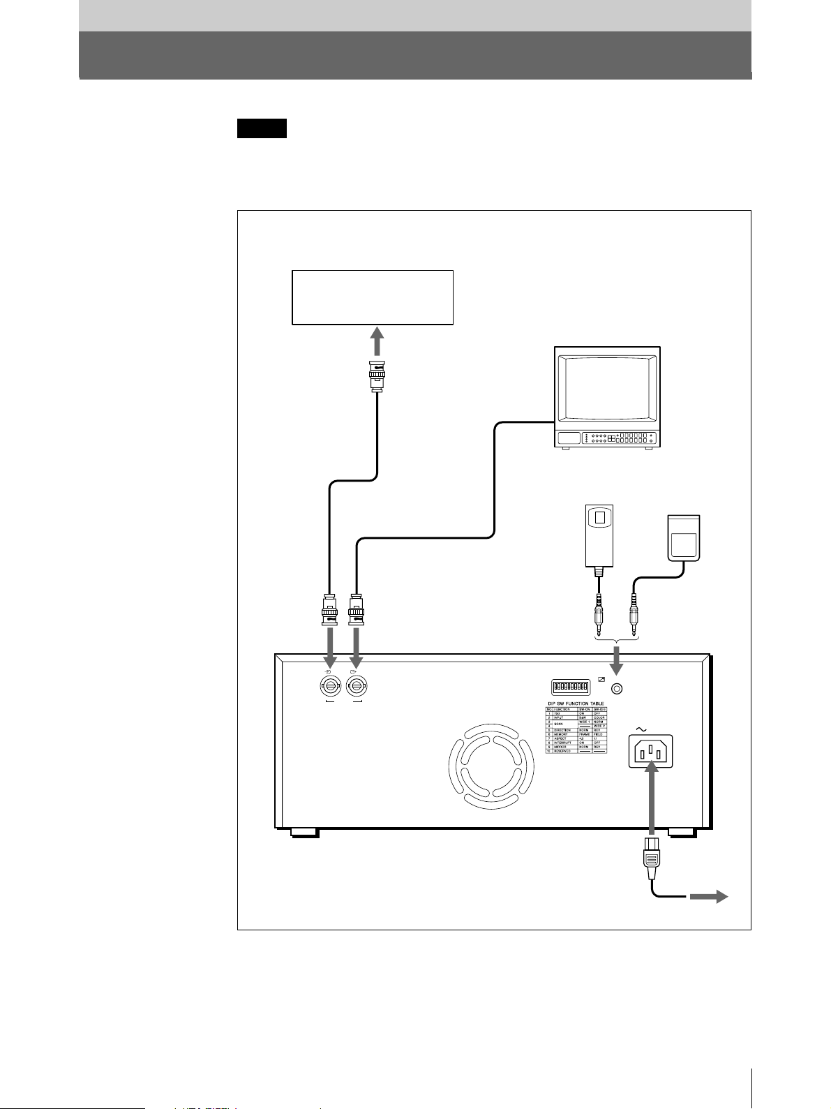
接続
ご注意
• 各機器の電源を切ってから、接続してください。
• 電源コードは最後に接続してください。
VIDEO IN
へ
ビデオ機器
(
a)
ビデオ出力へ
接続ケーブル(付属)
BNCyNC
VIDEO OUT
IN OUT
VIDEO
ビデオ入力へ
)
接続ケーブル(別売り)
へ
カラー/白黒モニター
リモートコント
ロールユニット
RM-91
REMOTE
へ
(別売り)
または
REMOTE
フットスイッチ
(別売り
FS-20
)
または医療診断装置など
a)
へ
AC IN
電源コード(付属)
AC IN
電源コンセントへ
準備
7
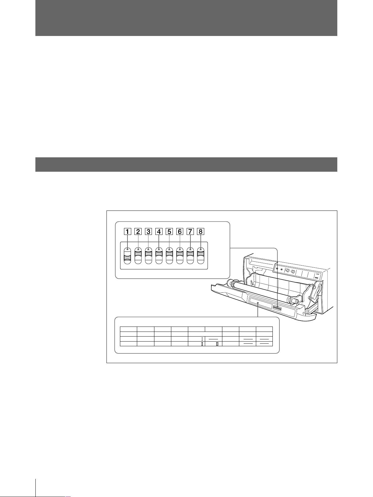
本機を使用状況に合わせる
DIPスイッチを使って、本機を使用状況に合わせて設定できます。
DIPスイッチは2種類あります。
• サブパネルにあるDIP スイッチ
使用頻度の高い動作モードの設定を行います。
• 裏面パネルにあるDIP スイッチ
比較的使用頻度の低い動作モード、プリンターの仕様などを設定します。
スイッチの設定を切り換えるには
DIP
小さいドライバーの先などで切り換えてください。
サブパネルにある
下図は工場出荷時の各スイッチの位置を示します。また、下図は工場出荷時の設定を表わしてい
ます。
DIP
1
F
O
NO
FUNCTION
ON
OFF
スイッチを切り換える
2
3
F
12345678
AGC
ON
OFF
5
4
IMAGE
SHARPNESS
POSI SOFT
HARD
NEGA
6
7
8
ON
OFF
GAMMA
TONE
TONE TONE
RESERVED RESERVED
POST FEED
ON
OFF
1
AGC(Automatic Gain Control
不適正なレベルの入力信号を、適切な入力レベルに補正します。
OFF (OFF):
ON (ON):
準備
8
通常はこの位 置に 設定します。
プリント画が全体に白っぼくなったり、黒っぽくなったりしたとき。
)切り換えスイッチ

2
IMAGE
POSI (ON):
NEGA (OFF):
(白黒反転)切り換えスイッチ
通常はこの設 定にします。
白黒を反転します。
3
SHARPNESS
SOFT (ON):
HARD (OFF):
4、5
GAMMA
印画のトーンを、TONEI、TONEII、TONEIIIのいずれかに切り換えます。
各トーンのカーブは図のようになっています。
TONEIII(5のOFF)に切り換えるとTONEI(4のON)/TONEII(4のOFF)の位置に関係
なくTONEIIIに設定されます。
濃
印画濃度
淡
0
(シャープネス)切り換えスイッチ
通常はこの設 定にします。
プリント画の 輪郭を強 調します。
(ガンマ)切り換えスイッチ
TONE III
TONE I
TONE II
階調
255
6
POSTFEED
ON (ON):
OFF (OFF):
たりの余白が少ないので用紙1巻あたりのプリント画 枚 数 が 多くとれます。ただし、ペーパーをカッ
トする時は、FEEDボタンを押してプリント用 紙を送り、カットしてください 。
7、8
RESERVED
通常は出荷状態(ON)のままにしておいてください。
(余白設定)切り換えスイッチ
プリントした後に余白をつけて紙送りするとき、この位置にします。
余白を少なくするときは、この位置にします。この位置にすると、プリント画 1 枚 あ
スイッチ
準備
9
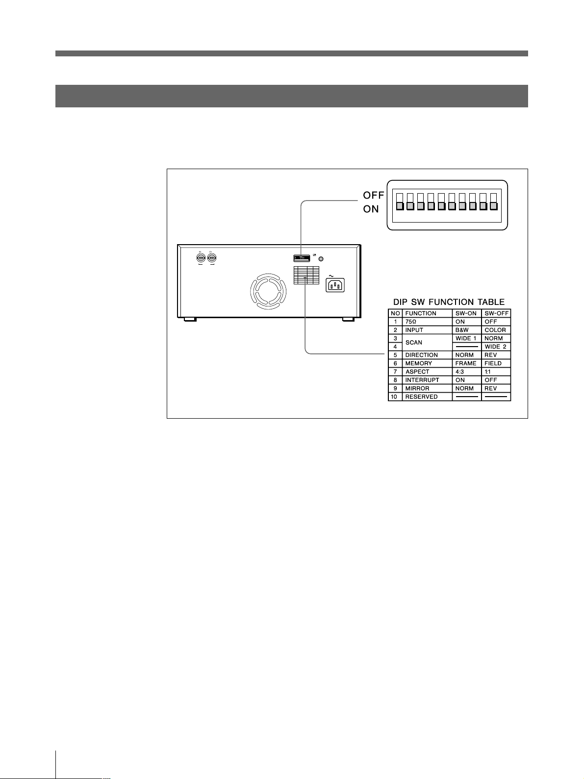
本機を使用状況に合わせる(つづき)
裏面パネルの
DIP
スイッチを切り換える
下図は工場出荷時の各スイッチの位置を示します。また、下図は工場出荷時の設定を表わしてい
ます。
IN OUT
VIDEO
REMOTE
ON
OFF
AC IN
1
Ω(インピーダンス)切り換えスイッチ
75
ON (ON):
VIDEOINコネクターに接続するビデオ機器に、プリンターを 1 台 だけつなくときは 、
この位置にします。
OFF (OFF):
VIDEOOUTコネクターからの出力信号をモニターテレビまたは他のビデオ機
器につなぐときは、この位置にします。
例:
映像を出力する機器にプリンターとモニターテレビを接続 する場 合tOFFにします。
映像を出力する機器に2 台のプリンターを接続する場合tどちらか 1台をO N、残り1台をOFFに
します。
2
INPUT
B&W (ON):
COLOR (OFF):
(入力信号)切り換えスイッチ
印画するビデオ信号が白黒のときはこの位置にします。
カラーのときはこの位置にします。
10
準備
3、4
275
87654321
475
50
250
9
4
5
5
7
5
4
3
3
2
3
2
30
10
7
0
3
275
87654321
475
50
250
9
4
5
5
7
5
4
3
3
2
3
2
30
10
7
0
3
275
87654321
475
50
250
9
4
5
5
7
5
4
3
3
2
3
2
30
10
7
0
3
275
87654321
475
50
250
9
4
5
5
7
5
4
3
3
2
3
2
30
10
7
0
3
275
87654321
475
50
250
9
4
5
5
7
5
4
3
3
2
3
2
30
10
7
0
3
SCAN
(スキャンサイズ)切り換えスイッチ
プリントする画像の範囲を切り換えます 。NORM、WIDE1、WIDE2の順にプリントす る範囲が 広
くなります 。WIDE2(4のOFF)に 切り換えると、NORM(3のOFF)/WIDE1(3のON)の位
置に関係なくWIDE2に設定されます。
1
2
3
3
5
2
3
30
4
3
3
4
1 357 7 531
4
3
3
4
30
3
2
5
3
3
2
1
NORM
5
DIRECTION
(プリント方向)切り換えスイッチ
印画方向を切り換えます。
NORM (ON):
REV (OFF):
1 357 7 531
画像を正方向(画面の下から先)にプリントするときは 、この位置にします。
逆方向(画面の上から先)にプリントするときは、この位置にします。
1
2
3
3
5
2
3
30
4
3
3
4
4
3
3
4
30
3
2
5
3
3
2
1
1
5
2
3
1
3
3
30
4
3
3
4
4
3
3
4
30
3
5
3
3
2
1
2
3
3
5
2
3
2
30
4
3
3
4
1 357 7 531
4
3
3
4
30
3
2
5
3
2
3
2
1
5
2
3
1
3
2
3
30
4
3
3
4
4
3
3
4
30
3
2
5
3
3
2
1
WIDE 1
5
2
3
1
3
2
3
30
4
3
3
4
4
3
3
4
30
3
2
5
3
3
2
1
1
2
3
3
5
2
3
30
4
3
3
4
4
3
3
4
30
3
2
3
1
3
2
5
1
2
3
3
5
2
3
30
4
3
3
4
1 357 7 531
4
3
3
4
30
3
2
5
3
3
2
1
WIDE 2
1
3
5
4
3
3
4
5
3
1
5
2
3
1
3
2
3
30
4
3
3
4
4
3
3
4
30
3
2
5
3
3
2
1
2
3
2
3
30
3
4
1 357 7 531
4
3
30
3
2
3
2
6
MEMORY
FRAME (ON):
FIELD (OFF):
NORM
(メモリーモード)切り換えスイッチ
通常はこの位置にしておきます。
動きの速い画像(ボールがバットに 当 た る 瞬 間 な ど )をプリントすると、画像が
REV
ぶれて二重になることがあります。このようなときは、この位置にします。
準備
11
本機を使用状況に合わせる(つづき)
275
87654321
475
50
250
9
4
5
5
7
5
4
3
3
2
3
2
30
10
7
0
3
275
87654321
475
50
250
9
4
5
5
7
5
4
3
3
2
3
2
30
10
7
0
3
7
ASPECT
4:3 (ON):
1:1 (OFF):
(アスペクト)比切り換えスイッチ
通常はこの位置にしておきます。
アスペクト比が1:1の画面をプリントす るときは、この位置にします。
1
2
3
3
5
2
3
30
4
3
3
1
2
3
3
5
2
3
30
4
3
3
4
1 357 7 531
4
3
3
4
30
3
2
5
3
3
2
1
5
2
3
1
3
3
30
4
3
3
4
4
3
3
4
30
3
5
3
3
2
1
2
2
4
1 357 7 531
4
3
3
4
30
3
2
5
3
3
2
1
5
2
3
1
3
2
3
30
4
3
3
4
4
3
3
4
30
3
2
5
3
3
2
1
4 : 3 1 : 1
8
INTERRUPT
ON (ON):
(プリント中断)切り換えスイッチ
プリント中にもう1度PRINTボタンを押すと、プリントを中断し、PRINTボタンを押した
瞬間の画像を新たにプリントします。SMALLモードのときは、プリントを中断し、1枚目の画像が取
り込まれます。
OFF (OFF):
プリント中にもう1度PRINTボタンを 押しても無 効になり、実行中のプリントを続け
ます。(ピッピッピッとアラームブ ザーが 鳴ります。)
9
MIRROR
NORM (ON):
REV (OFF):
0
RESERVED
(左右反転)切り換えスイッチ
通常はこの位置にしておきます。
左右を反転してプリントするときは 、この位置にします。
スイッチ
通常は出荷状態(ON)のままにしておいてください。
12
準備
プリンター用紙を取り付ける
ご注意
• プリンター用紙を入れる際は、プリンター用紙の感熱面には触れないでください。指紋や汗、折り
目がつくと、プリント画の品質の低下につながります。
• 用紙は専用のUPP-210シリーズをご使用ください。(23 ページ)
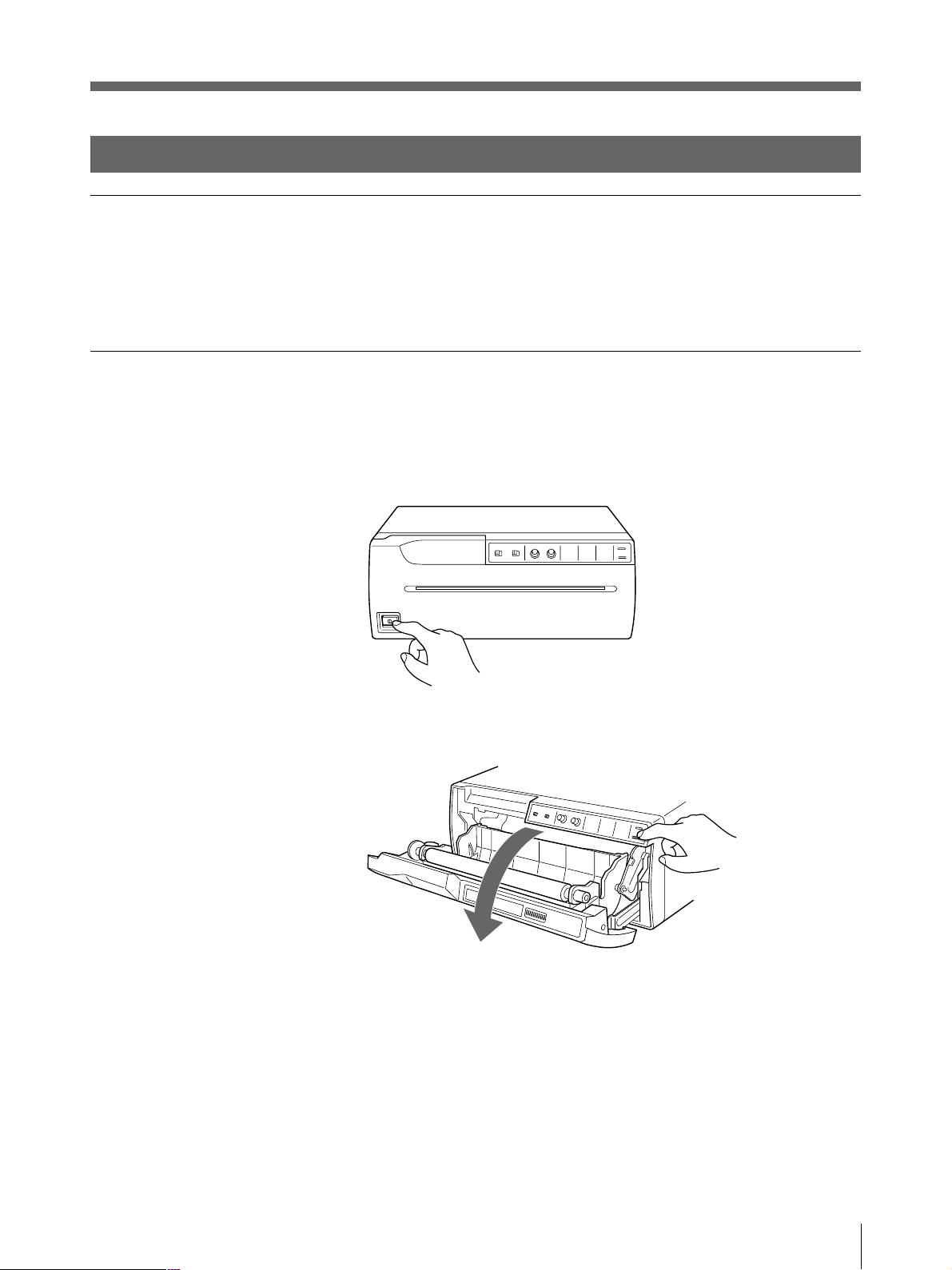
1 電源ON/OFFスイッチをON にし、電源を入れます。
フロントパネルのボタンが点 灯します。
2 OPEN/CLOSEボタンを押して、ドアパネルを開きます。
準備
13
プリンター用紙を取り付ける(つづき)
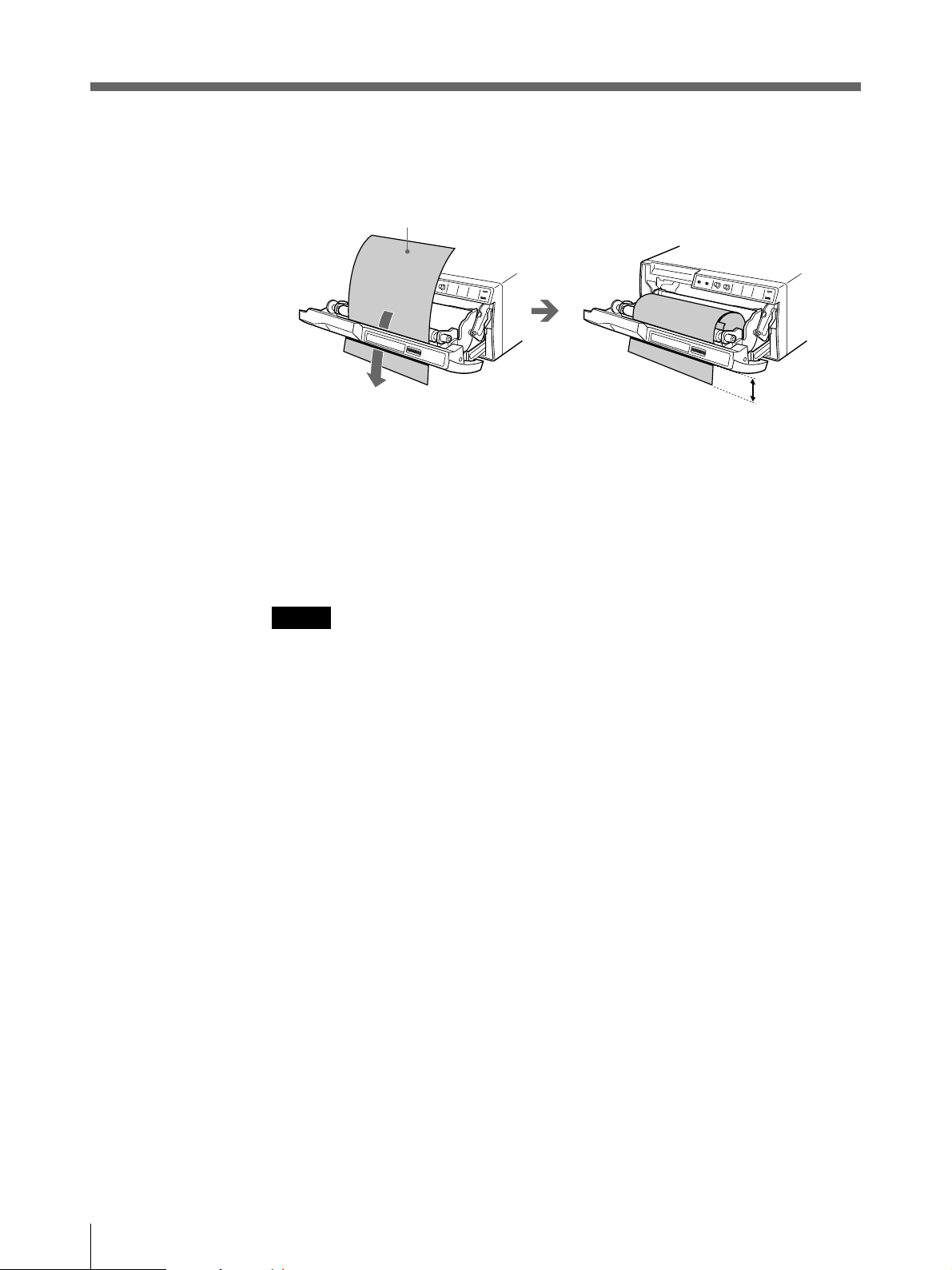
3 プリンター 用 紙をトレー内に入れます。
感熱面を上にして入れます。
逆に入れるとプリントされま
せん。
4 用紙を挿 入口から入れ、排紙口 から引き出します。
ご注意
挿入口の中心付近(ガイドの内側)に用紙をセットしてください。挿入口の端(ガイドの外側)に
用紙がセットされると紙づまりを起こすおそれがありますのでご注意ください。
14
ご注意
しわやたるみがないように用紙を引き出してください。
5 OPEN/CLOSEボタンを押して、ドアパネルを閉 めます。
ドアパネルは手で押して閉めることもできます。
ご注意
プリンター 用 紙を 取り付けたあとは、FEED ボタンを押して、15 〜20cm送ってからプリントしてくださ
い。
準備
操作
プリントする
・接続は正しいですか?(7 ぺージ)
・用紙は正しく取り付けてありますか?(13 ページ)
・DIPスイッチは正しく設定していますか?(8 〜12ページ)
・ビデオ信号が入力されていますか?
プリントする
プリントする前に次のことを確認してください。
12
FEED
ボタン
4
PAPER
EMPTY
OPEN/
CLOSE
ランプ
ボタン
1 電源ON/OFFスイッチをON にし、電源を入れます。
フロントパネルのボタンが点 灯します。
ご注意
PAPEREMPTYランプが消灯していることを確認します。
点灯している場合は、用紙がなくなっています。用 紙を取り付けてください 。
2 プリント画の 向きや大きさを選びます。
詳しくは、次ページの「プリント画の向き/大きさを選ぶには」をご 覧ください。
3 ビデオ機器などの入力源からの画像をモニターに映し出します。
この操作は、ビデオ機器など接続した機器側で行います。
4 プリントしたい画像が映っているときに、PRINTボタンを押します。
押した瞬間の画面がプリントされます。
プリントを中断するには
プリント中またはコピー中に、OPEN/CLOSE ボタン、またはFEEDボタンを押します。プリント動 作
は止まりま す 。
操作
15

プリントする(つづき)
プリントを中断して現在映っている画像をプリントするには
裏面のDIPスイッチ 8(INTERRUPT)が ONになっている状態で、プリント中またはコピー中に
PRINTボタンを押します。プリントは中断され、PRINTボタンを押した瞬間の画像が新たにプリント
されます。
プリント画がぶれていたら
速く動いている画像を取り込むと、画像がぶれてしまうこと が あります。このとき、裏面のDIPス
イッチ 6(MEMORY)の設定をFIELD に変えてプリントすることにより、プリント画 からぶ れを取り除
くことが で きま す 。この場合、解像度が少し落ちます。
SMALL
PRINTボタンを押してください。1 度押すとピッとブザーが鳴り、そのときの画像が取り込まれます。
さらに 2 度 目を押すと、2 枚目の画像が取り込まれてプリントが 始 まります。
モードでプリントするとき
同じ画像をもう1度プリントするには
COPYボタンを押します。最後にプリントした画像と同じものがプリントされます。最後にプリントした
画像はプリンター 内 部に記憶され て おり、この画像は他の画像をプリントす るか 、プリンターの電 源
を切るまで、残っています。
画像の向きを変えてコピーするには
最後にプリントした画像を違う向きでコピーすることができます。
「プリント画の向きを選ぶには」で向きを選んでから、COPYボタンを押します。
ご注意
• 電源を入れた直後など、プリンターに画像が記憶されていない状態でCOPYボタンを押すと、ア
ラームブザーが鳴り、コピーできません。
• SMALLモードで、1度しかPRINTボタンを押していない状態でCOPYボタンを押すと、アラームブ
ザーが鳴り、コピーできません。
16
同じ画像を連続してコピーするには
PRINTボタンまたはCOPYボタンを押して1枚目をプリント中にCOPYボタンを押します。COPYボ
タンを押し た 時 に ブ ザ ー が ピッと鳴 り、COPYボタンを押した数だけ(最初の 1枚を含めて最大11
枚)連続コピーできます。
途中で止めるには
OPEN/CLOSEボタン、またはFEEDボタンを押します。
操作
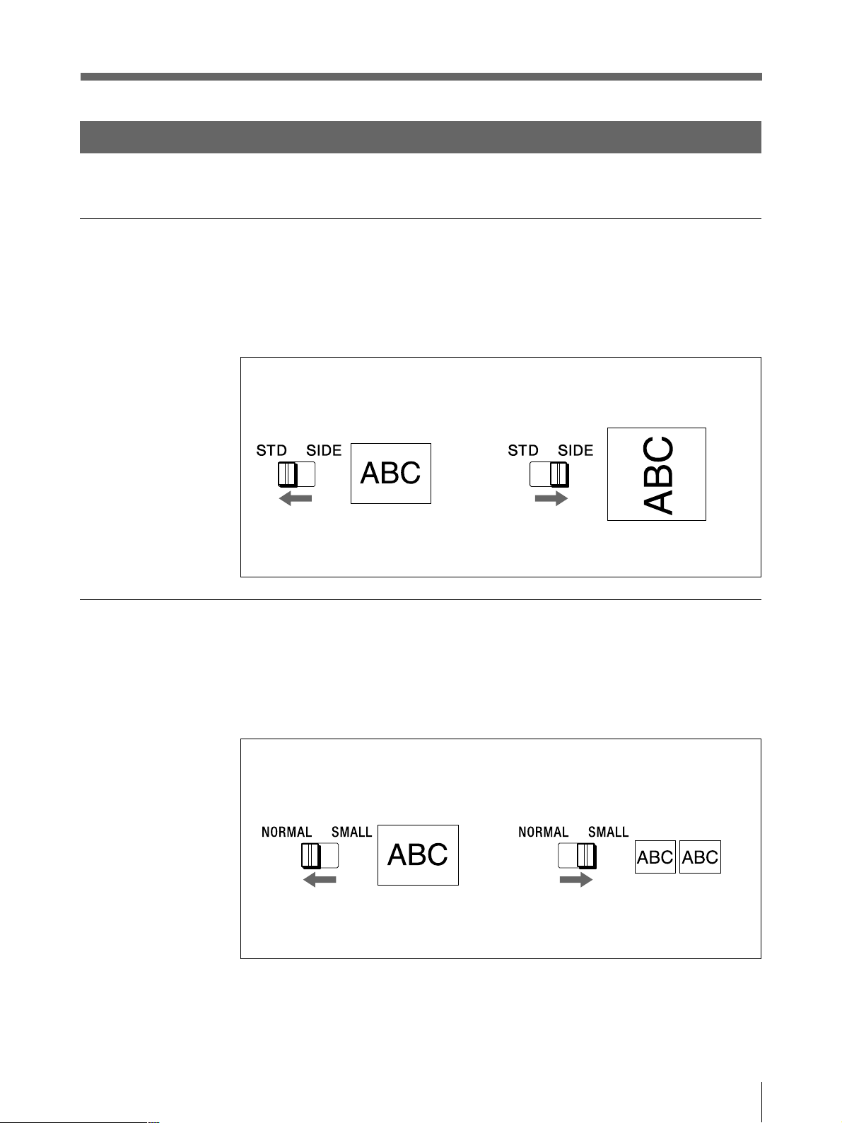
プリント画の向き/大きさを選ぶ
IMAGESIZE切り換えスイッチおよびDIP スイッチにより、色々なプリント画を 作 ることが で きます。
プリント画の向きを選ぶには
IMAGESIZESTD/SIDE切り換えスイッチ で、縦向きか横向きかを選ぶことができます。
縦向きにするときは、 STD(標準)側にします。
横向きにするときは、 SIDE(横)側にします。
プリント画の大きさを選ぶには
IMAGESIZENORMAL/SMALL切り換えスイッチで画像を縮小することができます。
標準サイズでプリントするには、 NORMAL(標準)側にします。
小さいサイズでプリントするには、 SMALL(縮小)側にします。
操作
17
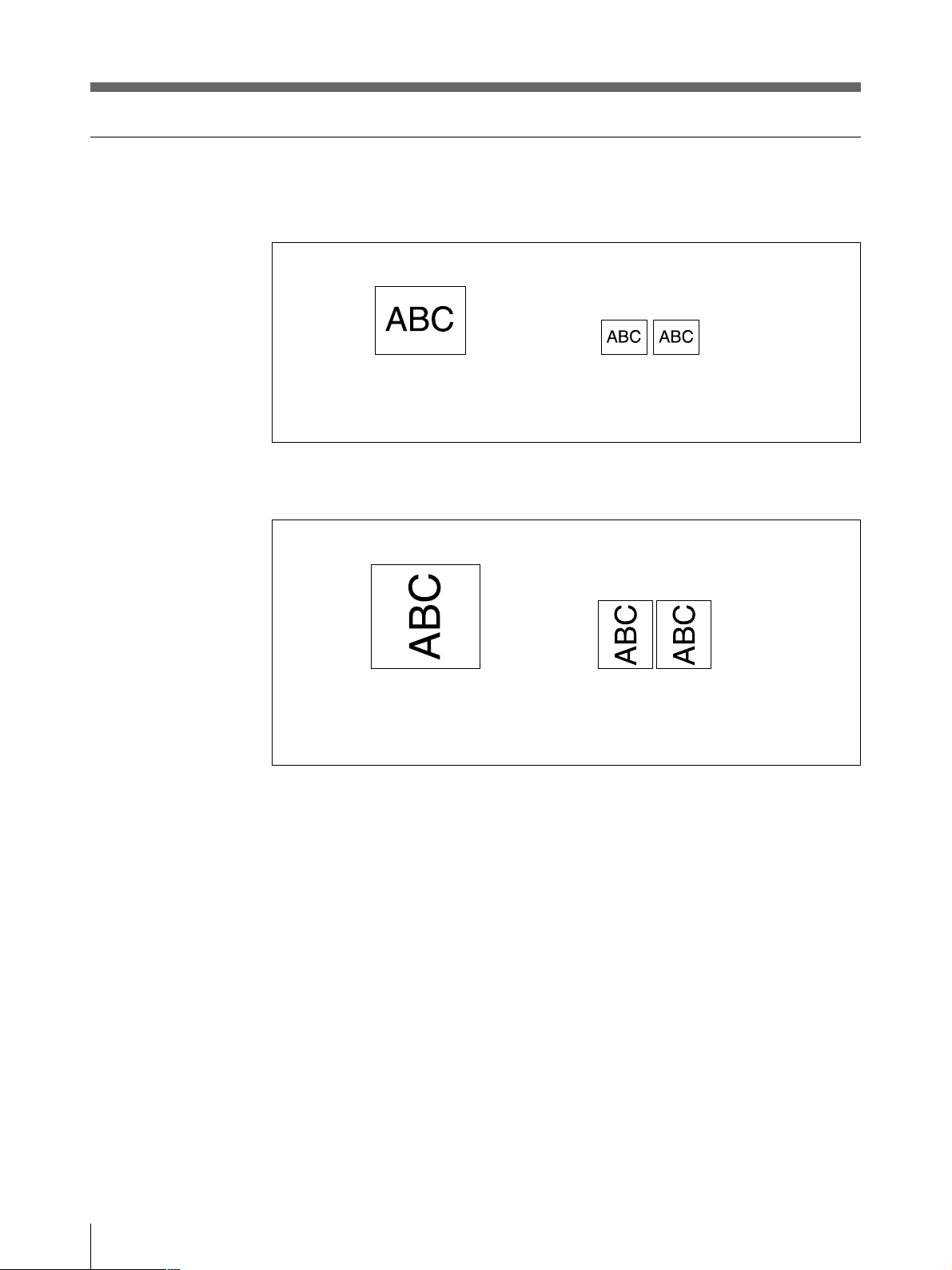
プリントする(つづき)
色々なプリント画
(標準)モード
STD
NORMAL
(横)モード
SIDE
NORMAL
上記の他に、DIPスイッチの設 定を変えることにより、次のプリント画 を 作 ること できます。
• 白黒反転のプリント画( 9 ペ ージ )
• 左右反転のプリント画(12 ページ)
• 上下逆のプリント画(11 ページ)
SMALL
SMALL
18
操作
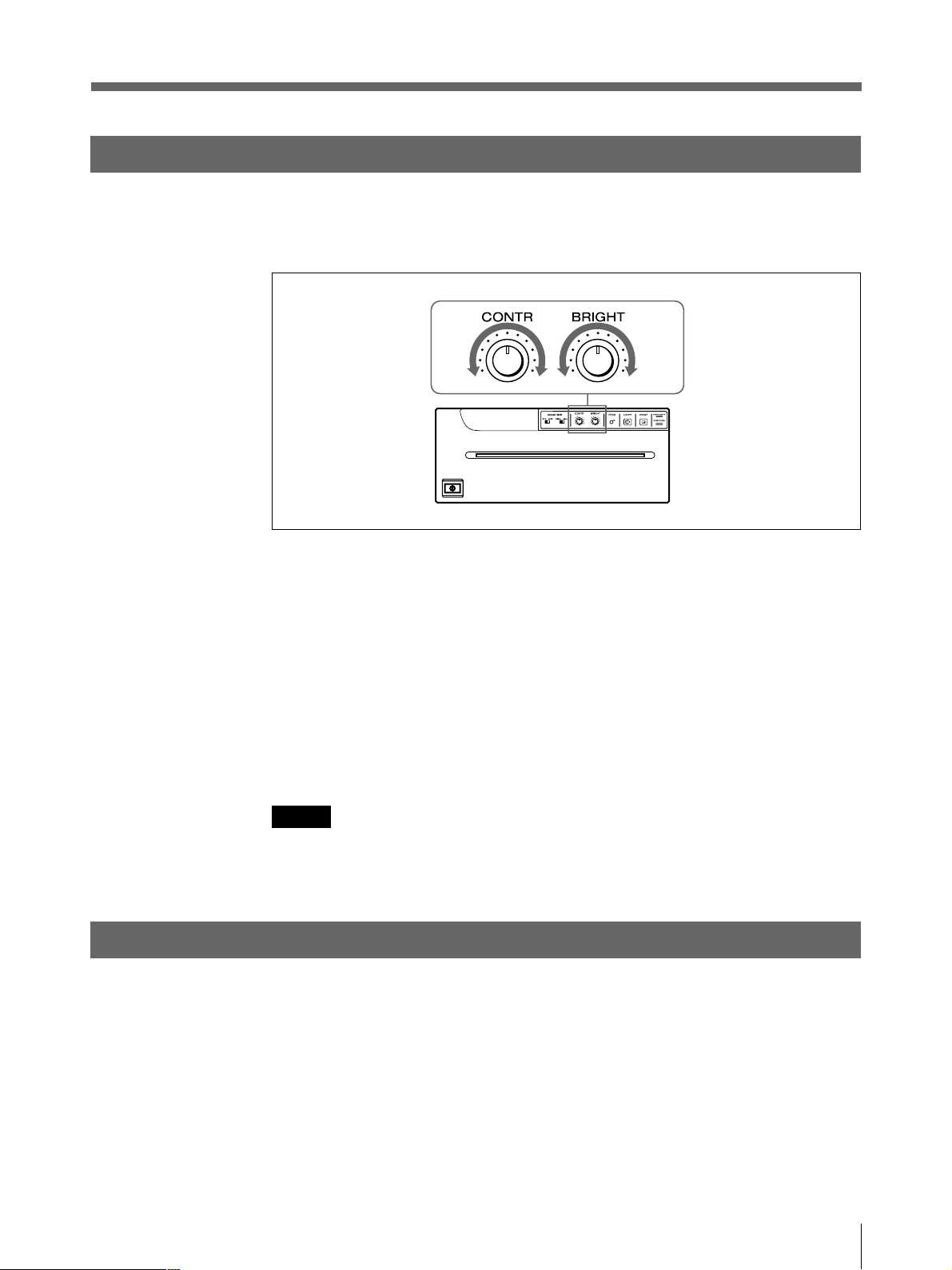
明るさやコントラストを調節する
プリンター前面のCONTRつまみ/BRIGHT つまみを使ってプリント画 の 明るさとコントラストを調節
できます。
コントラストを調節するには
プリンター前面のCONTRつまみを使って調節します。
コントラストを強くするには、 CONTRつまみを時計方向に回します。
コントラストを弱くするには、 CONTRつまみを反時計方向に回します。
明るさを調節するには
プリンター前面のBRIGHTつまみを使って調節します。
明るくするには、 BRIGHTつまみを時計方向に回します。
暗くするには、 BRIGHTつまみを反時計方向に回します。
ご注意
メモリーに取り込まれた 画 像 の 明るさやコントラストを 変えることは で きませ ん 。明るさ や コントラストを
変 更したいときは、画像を 取り込 む 前 に 調 節し てください。
プリント操作をリモートコントロールする
プリンター裏面のREMOTE端子に接続したリモートコントロールユニットRM-91、またはフットスイッ
チFS-20を使ってプリント操 作 をリモ ートコントロールできます。
リモコンのスイッチ を押すと、メモリーに画像が取り込まれ 、プリントされます。
プリンター裏面のDIPスイッチ 8 のINTERRUPTをONに設定しておくと(12ページ)、プリント
中、またはコピー中にリモコンのスイッチを 押 すと、プリントは中断され、スイッチを押した瞬間の画
像が新たにプリントされます 。
操作
19

その他
本機の性能を保持するために
本機の性能を保持するために、「安全のために」(2ページ)、「 」(3ページ)、
「
使用するときのご注意
長い間ご使用にならないときは、本体の電源スイッチを 切り、電源コードをコンセントから抜いてくだ
さい。
輸送について
• ぶつけたり、落としたりしないように気をつけてください。
• 持ち運びの際は、プリンター用紙を 取り外してください。プリンター用 紙を取り付 けたまま持ち運 ぶ
と故障の原因になることがあります。
設置するときのご注意
次のような場所に設置または保管しないでください
• 直射日光の当たるところ
• 湿気の多いところ
• 極端に暑いところや寒いところ
• 振動の多いところ
• ほこりの多いところ
• 不安定なところ
」(4ページ)と併せてご覧ください 。
結露について
湿度の低い場所から暖かい場所に移動したり、暖房で湯気や湿気がたち込めた部屋に置くと、本
機の内部に水滴がつくことが ありま す 。これを結 露といいます。この状態で本機を使用すると、正
常に動かないばかりでなく、故障の原因になります。結露の可能性のあるときは、電源を切り、し
ばらくそのまま放置しておいてください 。
クリーニングについて
• お手入れの際は、必ず電源を切って電源プラグを抜いてください。
• キャビネットの汚れがひどいときは、水または水で薄めた中性洗剤溶液で湿らせた布をかたくし
ぼって から、汚 れをふきとってください。このあと乾い た布で からぶきしてください。
• シンナーやベンジン、アルコール、化学ぞうきんなどは、表面の仕上げをいためることがありますの
で、使用しないでください。
20
その他
お手入れ
キャビネットのクリーニング
キャビネットの汚れは、水または水で薄めた中性洗剤溶液で湿らせた布をかたくしぼってから、拭
き取ってください。シンナーやベンジン、アルコールなどは表面の仕上げを傷めることがありますの
で、使用しないでください。
ヘッドのクリーニング
プリント画に白いスジが生じたら、付 属 の ヘッドクリー ニ ン グ シ ートで ヘッドをきれ いにしてください。
1 電源ON/OFFスイッチをON にし、電源を入れます。
2 OPEN/CLOSEボタンを押し、ドアパネルを開きます。
º
次のページに続く c
その他
21
本機の性能を保持するために(つづき)
3 付属のヘッドク リーニングシートの黒い面を下にして、トレーにおき、挿入口より入れ、排紙口よ
り少 し引き出 します。
クリーニングシートの黒い面を
下にして入れる。
4 OPEN/CLOSEボタンを押し、そのまま押し続けます。
ドアパネルが閉じ、 ク リーニング が 始 まります。
ブザーが鳴り、クリー ニングシートが排出され始めたら、OPEN/CLOSEボタンを離します。
2〜3cm
5 クリー ニングシートの排出が止まり、 クリーニング が 終 わりましたら、 OPEN/CLOSEボタンを押し
てドアパネルを開き、 ヘッドクリーニングシートを引き 出して取り除きます。
ご注意
ヘッドクリーニ ングシートは必要に応じてお使いください。 ヘッ ドの クリーニングを頻繁に行うと、故
障の原因になることがあります。
22
その他

プリンター用紙について
プリンター用紙の種類
用紙は必ず下記の本機専用のプリンター用紙をお使いください。他のプリンター用紙をお使いにな
ると、プリントした画面の品質が保証できないばかりでなく、プリンターの故障の原因となります。
— UPP-210SE(印画濃度= Normal(普通))
— UPP-210HD(印画濃度= HighDensity(高濃度))
プリンター用紙を保管するには
• 用紙やプリントした用紙は、直射日光、室内光を避け、暗い、低湿、低温(30℃以下)の場所に保
管してください。プリントした用紙はポリプロピレン の 袋、フォトアルバム等でキャビネット内に保 管
することをおすすめします。
• 用紙がアルコールなどの揮発性有機溶剤に触れたり、セロハンテープや塩化ビニールなどに密着
すると、プリントした画面が薄くなることがありますので、保管の際はご注意ください 。
• プリントした用紙をジアゾ式の湿式コピー(青焼)と重ねないでください 。黒く変色 することがありま
す。
• 用紙を接着するときは、両面テープまたは水性のりをお使いください 。
その他
23

主な仕様
感熱ヘッド薄膜サーマルヘッド(ドライブ I C 内 蔵 )
1280ドット
階調数 256階調
有効画素数 EIA:1280×507ドット
CCIR:1280×607ドット
画面寸法(初期設定時)
STD(STANDARD)モード、WIDE1 のと
き
EIA:190×144mm
CCIR:190×142mm
SIDEモードのとき
EIA:243×184mm
CCIR:243×181mm
プリント速度 EIA:約10秒/1 画面
CCIR:約12秒/1 画面
(アスペクト比4:3のとき)
ピクチャーメモリー
2048× 1024× 8bit
入力端子 VIDEOIN(BNC)
EIAまたはCCIR方式コンポジットビデオ信
号:1.0Vp-p、75Ω/ハイインピ ーダンス
切り換え方 式(EIA/CCIR自動判別方
式)
出力端子 VIDEOOUT(BNC)
EIAまたはCCIR方式コンポジットビデオ信
号:1.0Vp-p、75Ω ループスルー
リモ ート端子 REMOTE(ステレオミニジャック)
端子仕様
3
2
1
1 GND
2 PRINTSIGNAL(TTL)
100msec以上LOWのパルスが入力さ
れるとプリントが開始されます。
3 PRINTBUSY(TTL)
プリント中はHIGHレベルになります。
電源 AC100V、50/60Hz
消費電力 40W(スタンバイ時)
220W(プリント時 )
動作温度 5°C〜35°C
保管/輸送温度 –20°C〜60°C
動作湿度 20% 〜80%
保管/輸送湿度 20%〜90%
最大外形寸法 316×132×305mm(幅/高さ/奥行き)
質量 8kg(本体のみ)
付属品 プリンター用紙(UPP-210HD)(1)
75Ω同軸ケーブル(BNC −BNCケーブ
ル)(1)
AC電源コード(1)
3P−2P AC 変換アダプター(1)
ヘッドクリーニングシート(1)
取扱説明書(1)
サービス窓口のしおり・ご相談窓口の
ご案内(1)
保証書(1)
24
本機の仕様および外観は、改良のため予告なく変更するこ
とがありますが、ご了承ください。
その他

保証書とアフターサービス
保証書
この製品には保証書が添付されていますので、お買い上げの際お受け取りください。所定事項の
記入および記載内容をお確かめのうえ、大切に 保 存し てください。
アフターサービス
調子が悪いときはまずチェックを
この説明書をもう一度ご覧になってお調べください。
それでも調子の悪いときはサービスへ
お買い上げ店、またはお近くのソニーサービス窓口にご相談ください。
保証期間中の修理は
保証書の記載内容に基づいて修理させていただきます。詳しくは保証書をご覧ください。
保証期間経過後の修理は
修理によって機能が維持できる場合は、ご要望により有料修理させていただきます。
部品の保有期間について
当社では、ビデオプリンターUP-960 の補修用性能部品(製品の機能を維持するために必要な部
品)を、製造打ち切り後最低 10 年保有しています。この部品保有期間を修理可能の期間とさせて
いただきます。保有期間が経過した後も、故障箇所によっては、修理可能の場合がありますので、
お買い上げ店か、サービス窓口にご相談ください 。
その他
25

故障とお考えになる前に
修理にお出しになる前にもう一度点検してください。それでも正常に動作しないときは、お買い上
げ店またはソニーのサービス窓口にお問い合わせください。
こんなときは
ご確認ください
細かいゴミが最初にプリント
した数 枚に現れる。
PRINTボタンを押してもプリ
ントできない。
プリント画の周囲に黒い線が
できる、または 周囲 が欠け
ている。
紙詰まりが起きた。
プリンター用紙を交換したばかりではありませんか?
t FEEDボタンを押して、紙を少し引き出してからプリントしてください 。
(14ページ)
• 用紙が送られない場合
t 電源は入っていますか?
t 正しく接続されて います か?(7 ページ)
t 用紙がたるんでいませんか?(14 ページ)
t SMALL モードのとき、2 度PRINTボタンを押しましたか?
(16ページ)
• アラームブ ザー が鳴った 場 合
t サーマル ヘッドが温度 上昇していませんか? 真っ黒に近い画像
を連続してプリントすると、サーマルヘッドの温度が上昇する場合
があります。この場合、PAPEREMPTYランプが点滅しています。
しばらくプリントをやめてください 。
t プリントしたい信号は入力されていますか?
t 用紙は正しく取り付けてありますか?
• 用紙は送られるがプリントされない場合
t 用紙の感熱面を上にして取り付けましたか?(14ページ)
ビデオ信号によっては周囲に黒い線ができたり、周囲が欠けたりすること
があります。裏面のDIPスイッチのSCAN 切り換えスイッチを切り換えてくだ
さい。(11ページ)
• OPEN/CLOSEボタンを押してドアパネルを開け、プリンター 用紙を取
り出してから、詰まった紙を手 でゆっくり引き出し てください。
• プリンターが結露していませんか?
寒い所から急に暑い所にプリンターを移すと、内 部に水滴が つくこと
(結露)があります。結露したら電源を切ったまま1〜2時間放置してく
ださい。
26
その他
印画ムラが起きる
全面が真っ黒に近い画像を
連続してプリントし たら、プリ
ントしなくなってしまった。
(アラームブザーが 鳴る。)
白い線や小さい文字がぼけ
たり、二重に なっ て見える。
全体に細かいチェック模様
が見える。
プリント画が 明るすぎる、ま
たは 暗すぎる。
プリントされた画面が細長
い。
ヘッドが汚れ ていませ んか?
t 付属のヘッドクリーニン グ シ ートを 使って、ヘッドをきれいにしてくださ
い。(21 ページ)
真っ黒に近い画像を15 枚以上プリントすると、それ以上プリントしなくなるこ
とがありま す 。
t サーマル ヘッドの温度上昇を抑えるために保護回路が動作しているた
めです。しばらくプリントをやめてください。
白黒ビデオ信号に対して、裏面のDIPスイッチのINPUT 切り換えスイッチ
がCOLOR(OFF)になっていませんか。
t B&W(ON)の位置に設定してください。(10 ページ)
カラービデオ信号に対して、裏面のDIPスイッチのINPUT 切り換えスイッ
チがB&W(ON)になっていませんか。
t COLOR(OFF)の位置に設定してください。(10 ページ)
• 裏面のDIPスイッチの 7 5 Ω 切り換えスイッチ は 正しく設定してあります
か?(10ページ)
• サブパネルのDIP スイッチのGAMMA スイッチ は 正しく設定してありま
すか?(9 ページ)
裏面のDIPスイッチのASPECT 切り換えスイッチが 1 :1になっていません
か?
t 4 : 3 に 設 定してください。(12ページ)
各部の名称と働き
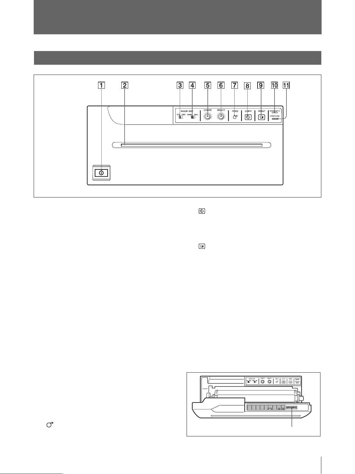
メインパネル
( )内の数字は、参照ページを示します。
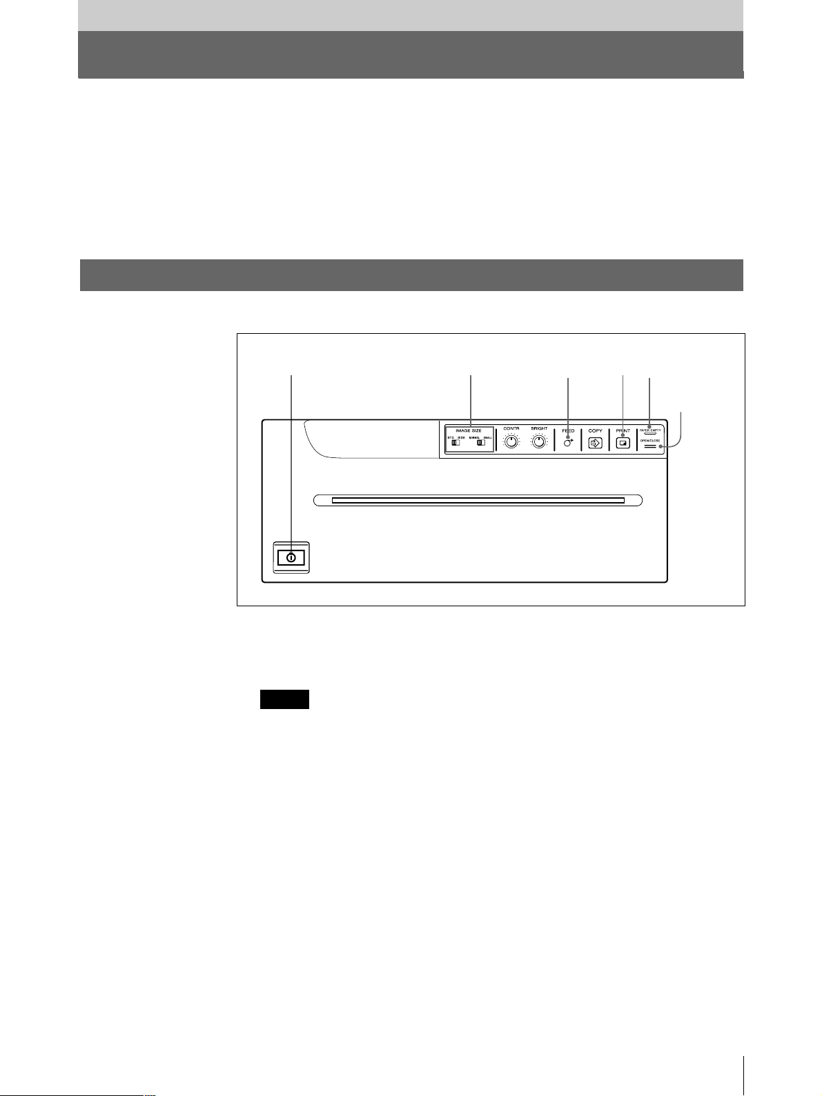
1
!
POWER
スイッチ(13、15、21)
本機の電源をON/OFF(入/切)します。FEED、COPY、
PRINTボタンが点灯します。
2 ペーパーフィーダーとカッター
プリント画を排紙口でカットするための刃がついていま
す。
3
IMAGE SIZE STD/SIDE
切り換えスイッチ(
(画像サイズ 標準/横)
)
17
縦向きにプリントするか横向きにプリントす るかを 選 択しま
す。
4
IMAGE SIZE NORMAL/SMALL
標準/縮小)切り換えスイッチ(
(画像サイズ
)
17
プリントする画像の大きさを選びます。
5
CONTR
(コントラスト)つまみ(19)
プリント画 のコントラストを 調節します。
8
COPY
ボタン(16)
最後にプリントした画像を再度プリントす るときに 押し ま
す。
9
PRINT
ボタン(15、16)
モニター画面上に表示されている画像をプリントす るとき
に押します。PRINTボタンを押した瞬間の画像はメモリー
に記憶されます。
0
PAPER/EMPTY
(紙無し)ランプ(15)
プリンター用 紙 が 無くなったときに点灯します。
qa
OPEN/CLOSE
16、21、22
(開/閉)ボタン(13、14、15、
)
ドアパネルを開閉させるときに押します。プリント中 に 押 す
と、プリントが中止されます。
OPEN/CLOSEボタンを押すと、次のサブパネルが現れ
ます。
6
BRIGHT
(明るさ)つまみ(19)
プリント画の 明暗を調 節します。
7
ボタン(14、15、16)
FEED
用紙を送るときに押します。押している間だけ用紙が送ら
れます。
プリント中 に 押 すと、プリントが中止されます。
NO
12345678
FUNCTION
IMAGE
SHARPNESS
AGC
ON
OFF
GAMMA
ON
POSI SOFT
TONE
OFF
HARD
TONE TONE
NEGA
POST FEED
ON
OFF
DIP
RESERVED RESERVED
スイッチ
ON
OFF
ON
各DIPスイッチの機能については、8 ペ ージをご 覧くださ
い。
その他
27
各部の名称と働き(つづき)
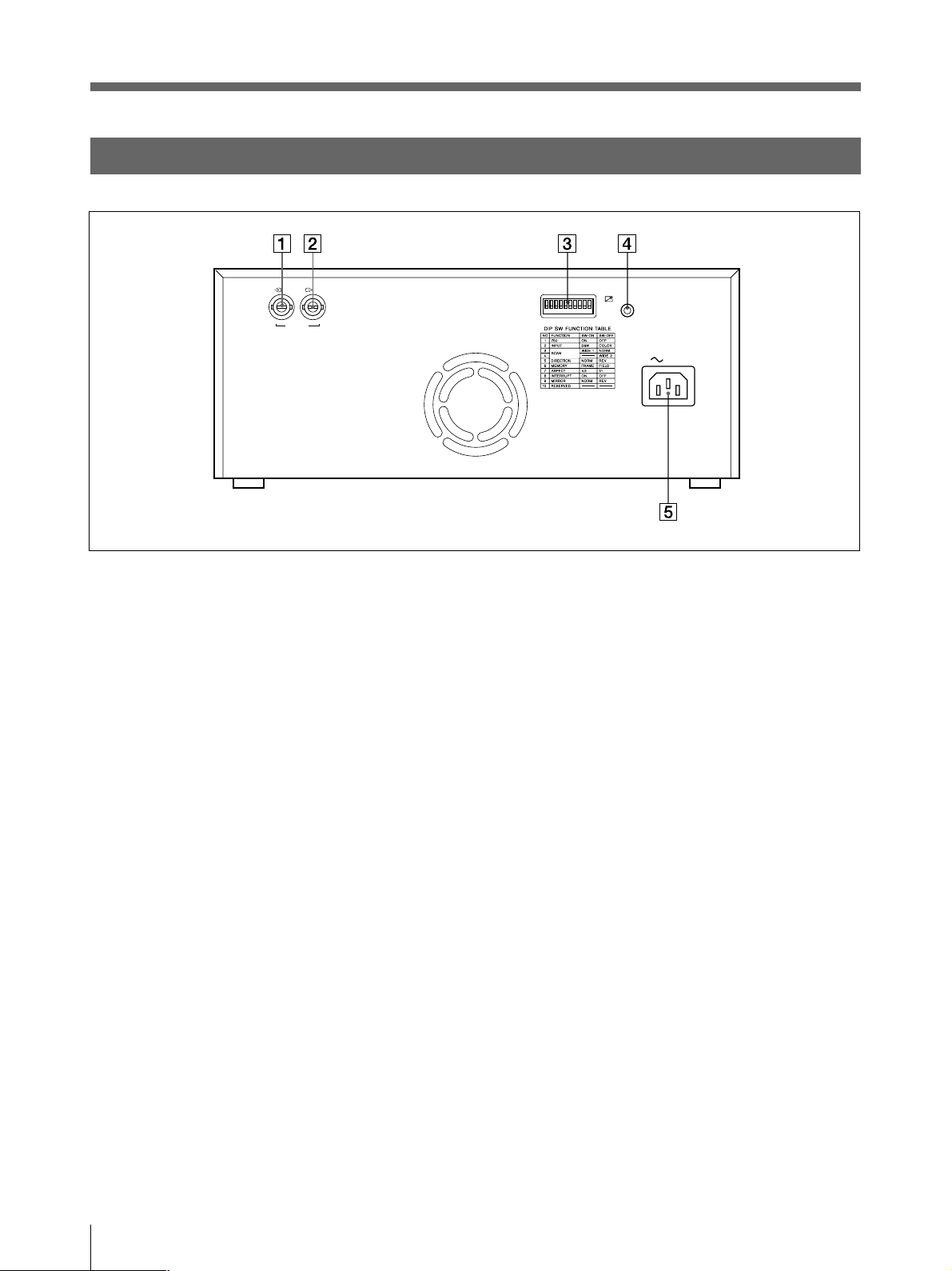
裏面
IN OUT
VIDEO
1 t
VIDEO IN
(映像信号入力)端子(
BNC
入力信号用のビデオ機器などと接続します。
2 T
IDEO OUT
(映像信号出力)端子(
BNC
モ ニターテレビと接続します。VIDEOIN端子から入力し
た信号がそのまま出力されます。
型)(7)
型)(7)
ON
OFF
REMOTE
AC IN
28
3
DIP SW
(ディップスイッチ)(10)
プリンターのプリントモードや機能を設定します。
4
(
REMOTE
7
(リモート)端子(ステレオミニジャック)
、19)
別売のリモコンRM-91フットスイッチFS-20と接続します。
5 -
(電源入力)端子(7)
AC IN
電源コード(付属)をつなぎます。
その他

その他
29

English
Owner’s Record
The model and serial numbers are located at the rear.
Record these number in the space provided below.
Refer to these numbers whenever you call upon your
Sony dealer regarding this product.
Model No.
Serial No.
WARNING
To prevent fire or shock hazard, do not expose the unit
to rain or moisture.
To avoid electrical shock, do not open the cabinet. Refer
servicing to qualified personnel only.
Symbol on the products
This symbol indicates the equipotential
terminal which brings the various parts of a
system to the same potential.
For the customers in the U.S.A.
This equipment has been tested and found to comply
with the limits for a Class A digital device, pursuant to
Part 15 of the FCC Rules. These limits are designed to
provide reasonable protection against harmful
interference when the equipment is operated in a
commercial environment. This equipment generates,
uses, and can radiate radio frequency energy and, if not
installed and used in accordance with the instruction
manual, may cause harmful interference to radio
communications. Operation of this equipment in a
residential area is likely to cause harmful interference in
which case the user will be required to correct the
interference at his own expense.
You are cautioned that any changes or modifications not
expressly approved in this manual could void your
authority to operate this equipment.
This device requires shielded interface cables to comply
with FCC emission limits.
For the customers in Canada
This unit has been certified according to Standard CSA
C22.2 No.601.1.
Important safeguards/notices for use in the
medical environments
1. All the equipments connected to this unit shall be
certified according to Standard IEC601-1, IEC950,
IEC65 or other IEC/ISO Standards applicable to the
equipments.
2. When this unit is used together with other equipment in
the patient area*, the equipment shall be either powered
by an isolation transformer or connected via an
additional protective earth terminal to system ground
unless it is certified according to Standard IEC601-1.
* Patient Area
R1.5m
3. The leakage current could increase when connected to
other equipment.
4. This equipment generates, uses, and can radiate
frequency energy. If it is not installed and used in
accordance with the instruction manual, it may cause
interference to other equipment. If this unit causes
interference (which can be determined by unplugging
the power cord from the unit), try these measures:
Relocate the unit with respect to the susceptible
equipment. Plug this unit and the susceptible equipment
into different branch circuit. Consult your dealer.
Warning on power connection for medical
use
Please use the following power supply cord.
With connectors (plug or female) and cord types other
than those indicated in this table, use the power supply
cord that is approved for use in your area.
United States Canada
Plug Type HOSPITAL GRADE* HOSPITAL GRADE*
Female end E62405, E35708 LR53182, LL022442,
LL088408
Cord type E159216, E35496 LL112007-1, LL20262,
Min.Type SJT LL32121, LL84494
Min.18AWG Min.Type SJT
Min.18AWG
Minimum cord 10A/125V 10A/125V
set rating
Safety UL Listed CSA
approval
*Note: Grounding reliability can only be achieved when
the equipment is connected to an equivalent
receptacle marked ‘Hospital Only’ or ‘Hospital
Grade’.
30

Table of Contents
Introduction
Preparation
Operation
Overview .......................................................................... 32
Connection ...................................................................... 33
Setting the DIP Switches ................................................34
Setting the DIP Switches on the Sub Panel .................... 34
Setting the DIP Switches on the Rear Panel .................. 36
Loading Paper ................................................................. 39
Printing............................................................................. 41
Making Printouts ............................................................ 41
Selecting the Printing Direction/Printing Size ............... 43
Adjusting the Contrast and Brightness ........................... 45
Remotely Controlling the Printer ................................... 45
EN
English
Others
Precautions...................................................................... 46
Maintenance ................................................................... 47
Paper ................................................................................ 49
Specifications .................................................................. 50
Troubleshooting .............................................................. 51
Location and Function of Parts and Controls ..............52
Front ............................................................................... 52
Back................................................................................ 53
Table of Contents
31

Introduction
Overview
The UP-960/960CE is a monochrome video graphic printer that reproduces images
from video equipment. Large size picture can be printed out quickly and easily
using the following features:
Clear and stable print quality
• High definition, 6.4 dots/mm printing
• 256 gradations of black and white.
• Stable printouts by the temperature compensation technology
• High density printouts using the UPP-210HD printing paper.
Two ways printing direction and two printing size selectable
• The printing direction selector on the front panel enables you to print in vertical
and horizontal directions.
• The printing size control on the front panel enables you to select two kinds of
printing size.
DIP switches to optimize the printer
• You can make printouts with bottom end first or upper part of the screen first by
using the DIRECTION DIP switch.
• Aspect ratio of printouts can be set to 4:3 or 1:1 by using the ASPECT DIP
switch.
• You can change the range to be printed out by using the SCAN DIP switch.
Fast printing
• You can make a single printout in about 10 seconds
• You can make a maximum of 11 copies of the same image continuously.
Automatic video signal discrimination
The type of input video signal (EIA or CCIR) is automatically discriminated and
printed adequately; there is no need to change any switch manually.
Easy and quick paper loading
You can load paper just by opening the door panel with the OPEN/CLOSE button
and placing the paper roll.
32
Introduction

Preparation
Connection
Notes
• Turn off the power to each device before making any connections.
• Connect the AC power cord last.
• Before making connections, see “Important safeguards/notices for use in the
medical environment” on page 30.
Video equipment/
Medical equipment
to video output connector
Color/black and white
video monitor
to video input
connector
to VIDEO IN
Supplied coaxial connecting
cable (BNC ˜ BNC)
Connecting cable
(not supplied)
to VIDEO OUT
IN OUT
VIDEO
RM-91 remote control
unit (not supllied)
a)
REMOTE
to AC IN
FS-20 foot switch
(not supllied)
or
to REMOTE
AC IN
a)
a) Connect either the RM-91 remote control
unit or the FS-20 foot switch.
Supplied AC power cord
to wall outlet
Preparation
33

Setting the DIP Switches
You can set the printer to the required print mode using the DIP switches.
The printer has two kinds of DIP switches;
• DIP switch on the sub panel
You can set the print mode frequently used in daily operation easily on the sub
panel.
• DIP switches on the rear panel
You can set the print mode and printer specifications you do not need to change
settings frequently.
How to change the DIP switch setting
Before setting the DIP switches, turn the power off. Change the settings using a
small pointed tool such as a small screwdriver.
Note
ON or OFF indicated in parentheses shows the switch setting position.
Setting the DIP Switches on the Sub Panel
The factory settings are as follows.
1
F
O
NO
FUNCTION
ON
OFF
2
3
F
12345678
AGC
ON
OFF
5
4
IMAGE
SHARPNESS
POSI SOFT
HARD
NEGA
6
7
8
ON
OFF
GAMMA
TONE
TONE TONE
RESERVED RESERVED
POST FEED
ON
OFF
1 AGC (Automatic Gain Control) switch
Adjusts the input signal to the optimum printing level.
OFF (OFF): Normally keep this switch set to this position.
ON (ON): When the printout image appears blackish or whitish, select this
position to adjust the input signal to the optimum level.
34
2 IMAGE switch
POSI (ON): Normally keep this switch set to this position.
NEGA (OFF): Makes negative printouts.
Preparation

3 SHARPNESS switch
SOFT (ON): Normally keep this switch set to this position.
HARD (OFF): Obtains greater sharpness of printouts.
4, 5 GAMMA switch
Sets the printing tone to one of TONE I, TONE II or TONE III.
The diagram below shows the curve of each tone for your reference.
When you set the GAMMA switch 5 to the OFF position (TONE III),
TONE III is selected regardless of the setting of the GAMMA switch 4
position.
High
TONE III
TONE I
Print density
Low
0
Gradation
TONE II
255
6 POSTFEED switch
ON (ON): Feeds out extra blank paper once a picture has been printed.
OFF (OFF): Does not feed out extra blank paper once a picture has been
printed. To save paper by feeding only a short length of paper after printing a
picture, set to this position. You can make more printouts per roll of printing
paper, but you have to feed the paper using the FEED button and tear off the
paper by yourself.
7, 8 RESERVED switches
Keep this switch set to ON.
Preparation
35

Setting the DIP Switches (Continued)
Setting the DIP Switches on the Rear Panel
The factory settings are as follows.
IN OUT
VIDEO
REMOTE
ON
OFF
AC IN
1 75Ω switch
ON (ON): When nothing is connected to the VIDEO OUT connector, set the
switch to this position.
OFF (OFF): When a video monitor or other video equipment is connected to
the VIDEO OUT connector, set the switch to this position.
When you connect two printers to one video equipment, set the 75Ω switch of
one of the printer to ON, and the other to OFF.
36
2 INPUT switch
B & W (ON): When the signal to be printed is black and white, set the switch
to this position.
COLOR (OFF): When the signal is color, set the switch to this position.
Preparation

3, 4 SCAN size switches
275
87654321
475
50
250
9
4
5
5
7
5
4
3
3
2
3
2
30
10
7
0
3
275
87654321
475
50
250
9
4
5
5
7
5
4
3
3
2
3
2
30
10
7
0
3
275
87654321
475
50
250
9
4
5
5
7
5
4
3
3
2
3
2
30
10
7
0
3
275
87654321
475
50
250
9
4
5
5
7
5
4
3
3
2
3
2
30
10
7
0
3
275
87654321
475
50
250
9
4
5
5
7
5
4
3
3
2
3
2
30
10
7
0
3
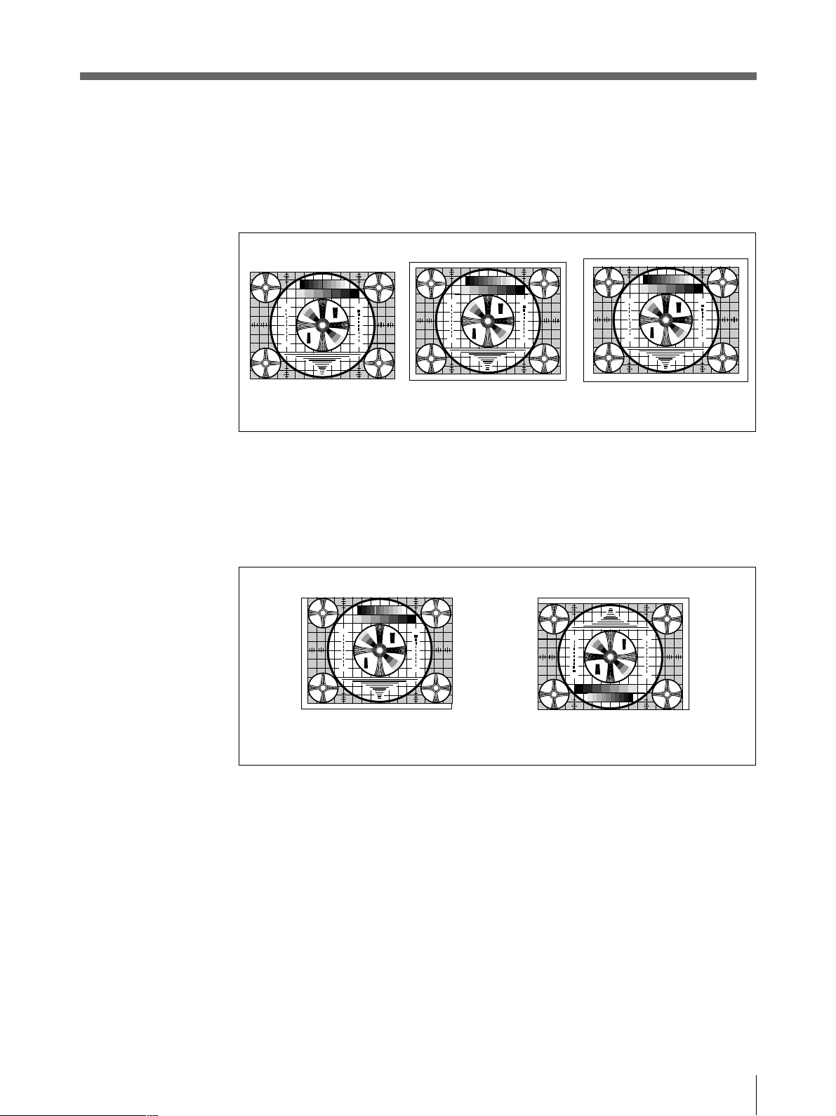
Set the printout range. The printout range is widened in the NORM, WIDE 1,
and WIDE 2 order.
NORM (Switch 3: OFF): Prints only the image displayed on the standard
screen size of the video monitor.
WIDE 1(Switch 3: ON): Prints when the signal scans beyond the edge of
the standard monitor screen.
WIDE 2 (Switch 4: OFF): To further extend the range, select this setting.
Note
If the SCAN switch 4 is set to the OFF position (WIDE 2), WIDE 2 is
selected regardless of the setting of the SCAN switch 3 position.
1
2
3
3
5
2
3
30
4
3
3
4
1 357 7 531
4
3
3
4
30
3
2
5
3
3
2
1
5
2
3
1
3
3
30
4
3
3
4
4
3
3
4
30
3
5
3
3
2
1
NORM
1
2
3
3
5
2
3
2
2
30
4
3
3
4
1 357 7 531
4
3
3
4
30
3
2
5
3
3
2
1
WIDE 1 WIDE 2
5
2
3
1
3
2
3
30
4
3
3
4
4
3
3
4
30
3
2
5
3
3
2
1
1
2
3
3
5
2
3
30
4
3
3
4
1 357 7 531
4
3
3
4
30
3
2
5
3
3
2
1
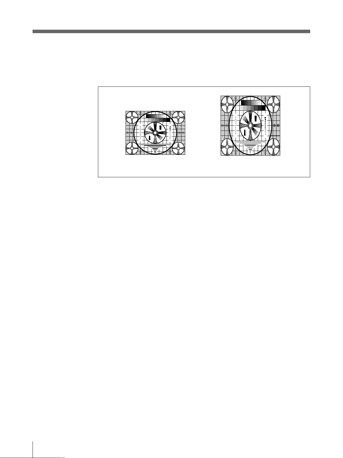
5 DIRECTION switch
Selects whether the top or the bottom of the screen is to be printed first.
NORM (ON): Normally keep this switch set to this setting. Printing is done
from the bottom of the screen.
REV (OFF): Printing is started from the top of the screen.
1
2
3
3
5
2
3
30
4
3
3
4
1 357 7 531
4
3
3
4
30
3
2
5
3
3
2
1
5
2
3
1
3
2
3
30
4
3
3
4
4
3
3
4
30
3
2
5
3
3
2
1
1
2
3
3
5
2
3
30
4
3
3
4
4
3
3
4
30
3
2
3
1
3
2
5
1
3
5
30
4
3
3
4
4
3
3
4
30
5
3
1
5
2
3
1
3
2
3
30
4
3
3
4
4
3
3
4
30
3
2
5
3
3
2
1
2
3
2
3
1 357 7 531
3
2
3
2
NORM
REV
6 MEMORY switch
FRAME (ON): Normally keep this switch set to this position.
FIELD (OFF): When printing fast moving pictures (such as a ball being
thrown), the printout may blur. If this happens, set to this position. The
printout definition will be poorer, but less blurred.
Preparation
37

Setting the DIP Switches (Continued)
275
87654321
475
50
250
9
4
5
5
7
5
4
3
3
2
3
2
30
10
7
0
3
275
87654321
475
50
250
9
4
5
5
7
5
4
3
3
2
3
2
30
10
7
0
3
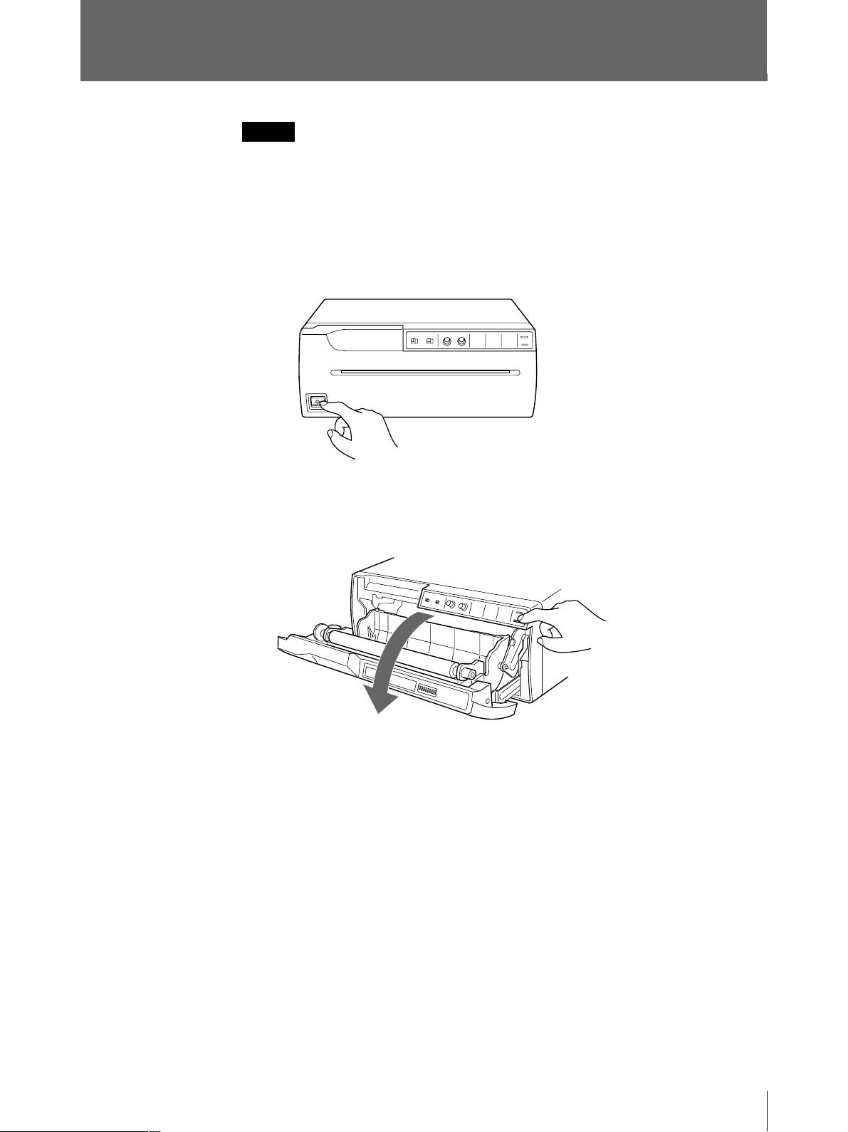
7 ASPECT switch
4:3 (ON): Normally keep this switch set to this position.
1:1 (OFF): When the aspect ratio of the video signal is 1:1, set to this
position.
The printout will be longer than a printout made at 4:3.
5
2
3
1
3
2
3
30
4
3
3
4
4
3
3
4
30
3
2
5
3
3
2
1
1
2
3
3
5
2
3
30
4
3
3
4
1 357 7 531
4
3
3
4
30
3
2
5
3
3
2
1
5
2
3
1
3
3
30
4
3
3
4
4
3
3
4
30
3
5
3
3
2
1
4 : 3
1
2
3
3
5
2
3
30
4
3
3
2
2
4
1 357 7 531
4
3
3
4
30
3
2
5
3
3
2
1
1 : 1
8 INTERRUPT switch
Sets whether the PRINT button is activated to enable interruption of the
printing process and capture an image in memory.
ON (ON): Interrupts the printing under way, captures the image displayed,
and prints a new picture.
In the SMALL mode, the printer stops printing and captures the first image.
OFF (OFF): Disregards that the PRINT button is pressed during printing and
continues the printing under way.
If you press the PRINT button during printing in OFF mode, the alarm buzzer
will sound.
9 MIRROR switch
NORM (ON): Normally keep this switch set to this position.
REV (OFF): Prints the right and left sides reversed (mirror image).
0 RESERVED switch
Keep this switch set to ON.
Preparation
38

Loading Paper
Notes
• Do not fold the paper or touch the printing surface. Any dust on the printing
surface will result in poor printing quality.
• Use only paper made specially for the UP-960 series. (See page 49.)
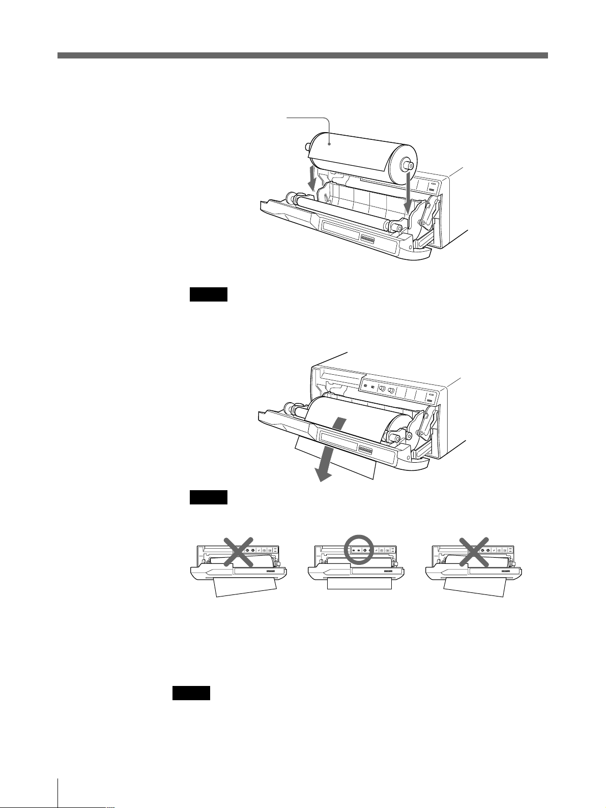
1 Press the power ON/OFF switch to turn on the printer.
The buttons on the front panel will light.
2 Press the OPEN/CLOSE button to open the door panel.
Continue to next page m
Prepration
39

Loading Paper (Continued)
3 Place the paper roll in the printer.
Place the paper with
the thermo-sensitive
side (printing side) up.
4 Insert the end of the paper end into the paper insertion slot and feed the paper
with your hand until its end comes out from the paper outlet.
Note
Be sure to set the paper in the middle of the paper insertion slot and between
the guides to avoid any paper jamming.
40
Prepration
Note
Be sure to remove any slack in the roll when pulling out the paper.
5 Press the OPEN/CLOSE button to close the door panel.
You can also close the door panel simply by pushing it.
Note
After loading the paper roll, press and hold down the FEED button until 15 to 20
cm (6 to 7
7
⁄8 inches) of the paper protrudes and tear it off by yourself.

Operation
Printing
Before making printouts
• Are the connections correct? (page33)
• Is the paper roll loaded properly? (page 39)
• Are the DIP switches set correctly? (page 34)
• Is the print source being input?
Making Printouts
1
24
FEED button
1 Press the power ON/OFF switch to turn on the printer.
All buttons on the front panel will light.
Note
Make sure that the PAPER EMPTY indicator is not lit.
If lit, load the paper. (See page 39.)
PAPER/EMPTY
lamp
OPEN/CLOSE
button
2 Selecting the printing direction and size.
See “Selecting the Printing Direction/Printing Size”. (See page 43.)
3 Start the video source.
This operation is done using the controls of the video equipment acting as a
source.
4 When the image you want to print is on the video monitor, press the PRINT
button.
The image displayed at the instant you press the PRINT button is captured into
memory and is printed out immediately.
To interrupt printing
Press either OPEN/CLOSE or FEED button while printing. The printer stops
printing.
Operation
41

Printing (Continued)
To stop printing and print another picture displayed on the video
monitor
To do this, the INTERRUPT setting of the DIP switches must be set to ON. (See
page 38.)
Press the PRINT button while printing or copying. The printer stops printing,
captures the new image, and starts printing of the new image.
In the SMALL mode, the printer stops printing and captures the first image.
If the printout image is blurred
A rapidly moving image may be blurred when printed. Should this occur, change
the MEMORY setting of the DIP switch to FIELD. (See page 37.)
To print in SMALL mode
Press the PRINT button twice. When you press the PRINT button once, the buzzer
sounds and the first image is captured. The printer starts printing after the PRINT
button is pressed twice.
For detailed information on SMALL mode, see “Selecting Printing Direction/
Printing Size”. (See page 43.)
Making copies of the last printout
Press the COPY button. The printer makes a copy of the last printout. The image of
the last printout is retained in the printer’s memory until you press the PRINT
button again or turn the power off.
To copy in different sizes
You can copy the last printout in different sizes.
Before pressing the COPY button, select the printing size as described in
“Selecting the printing size” (See page 43.)
Notes
• If you press the COPY button immediately after turning the power on, the alarm
buzzer will sound as nothing is stored in memory.
• In the SMALL mode (page 43), if you press the COPY button after you have
pressed the PRINT button only once, the alarm buzzer will sound and the printer
will not copy.
To make multiple copies of the same printout
Press the COPY button as many times as necessary (maximum 11 copies including
the first printout) while printing or copying the first printout. Each time you press
the COPY button, the short buzzer sounds.
42
To interrupt copying
Press either OPEN/CLOSE or FEED button.
Operation

Selecting the Printing Direction/Printing Size
You can make variations of printouts using the IMAGE SIZE selectors and the DIP
switches.
Selecting the printing direction
You can select the vertical or horizontal direction using the IMAGE SIZE STD/
SIDE selector.
To print in the vertical direction: Set to STD.
To print in the horizontal direction: Set to SIDE.
Selecting the printing size
You can print in normal or small size by changing the IMAGE SIZE NORMAL/
SMALL selector.
To print in normal size: Set to NORMAL.
To print in small size: Set to SMALL.
Operation
43

Printing (Continued)
Variations of printouts
STD (standard) mode
SIDE mode
NORMAL SMALL
NORMAL SMALL
In addition to printouts introduced above, you can make the following variations
by changing the DIP switch settings.
• Making negative printouts. (See page 34.)
• Making mirror image printouts. (See page 38.)
• Making printouts upside down. (See page 37.)
44
Operation

Adjusting the Contrast and Brightness
You can adjust the contrast and brightness of the printout.
To adjust the contrast
You can adjust the contrast of printouts using the CONTR control.
To make the contrast stronger: Turn the CONTR control clockwise.
To make the contrast weaker: Turn the CONTR control counterclockwise.
To adjust the brightness
You can adjust the brightness of printouts using the BRIGHT control.
To make the brightness brighter: Turn the BRIGHT control clockwise.
To make the brightness darker: Turn the BRIGHT control counterclockwise.
Note
You cannot adjust the image once it has been captured in memory. Restore an
image after adjustment.
Remotely Controlling the Printer
You can remotely control the printer using the RM-91 remote control unit or the
FS-20 foot switch connected to the REMOTE connector on the rear panel.
Since the button on the remote control unit or foot switch functions exactly same as
the PRINT button, pressing either of them results in an image being captured and
immediately printed, when the INTERRUPT switch 8 of the DIP switches on the
rear panel is set to ON. (See page 38.)
Operation
45

Others
Precautions
On the safety
• Check the operating voltage before operation.
• Stop operation immediately if any liquid or solid objects fall into the cabinet.
• Unplug the unit from a wall outlet if you will not be using it for a long time.
• Do not disassemble the cabinet. Refer servicing to qualified personnel only.
• Do not touch the cutting blade of the printer.
• Keep fingers clear of paper lid assembly and paper cutting blade when paper lid
• Connect the power plug of the printer to a wall outlet that is safely grounded.
On operation
Do not turn the power off while the printer is printing. The thermal head may be
damaged.
Operate the unit only with a power source specified in the “Specifications”.
Unplug the unit and have it checked by qualified personnel.
Disconnect the power cord by grasping the plug. Never pull the cord itself.
is closing.
On printer carriage
On installation
Do not carry and move the printer when a paper roll is being placed in the printer.
Doing so may cause malfunction.
• Place the printer on a level and stable surface during operation.
• Do not install the printer near heat sources. Avoid locations near radiators or air
ducts. Also do not subject to direct sunlight or excessive dust, humidity,
mechanical shock or vibration.
• Provide adequate air circulation to prevent heat buildup. Do not place the printer
on surfaces such as rugs, blankets, etc., or near materials such as curtains and
draperies.
• If the printer is subjected to wide and sudden changes in temperature, such as
when it is moved from a cold room to a warm room or when it is left in a room
with a heater that tends to produce large amounts of moisture, condensation may
form inside the printer. In such cases the printer will probably not work properly,
and may even develop a fault if you persist in using it. If moisture condensation
forms, turn off the power and allow the printer to stand for at least one hour.
46
Others

Maintenance
Cleaning the cabinet
Do not use strong solvents to clean the printer. Thinner or abrasive cleansers will
damage the cabinet.
Cleaning the thermal head
If the printout is dirty or white stripes appear on the printouts, clean the thermal
head using the supplied cleaning sheet.
1 Press the power ON/OFF switch to turn on the printer.
2 Press the OPEN/CLOSE button to open the door panel.
Remove the paper roll if loaded in the printer.
Continue to next page m
Others
47

Precautions (Continued)
3 Insert the cleaning sheet, with the black surface facing down, into the paper
insertion slot and feed the paper with your hands until the end comes out from
the paper outlet.
Cleaning sheet (supplied)
Insert the cleaning sheet into
the paper insertion slot.
2 to 3 cm
4 Press the OPEN/CLOSE button and keep it pressed.
The door panel closes and the printer starts cleaning the head.
When the buzzer sounds and the printer starts ejecting the cleaning sheet,
release the OPEN/CLOSE button.
5 Press the OPEN/CLOSE button to open the door panel when the head cleaning
is completed and the printer stops ejecting the cleaning sheet, and remove the
cleaning sheet.
Notes
• Do not press the PRINT button while the cleaning sheet is in the printer.
• Clean the head only when necessary. If you clean the head too often, it may
cause a malfunction.
48
Others

Paper
Type of paper
Storing paper
• Use only paper specified for this printer. The use of other paper may result in
reduced printer performance and poor print quality.
• The following types of paper are available.
— UPP-210SE (Normal)
— UPP-210HD (High density)
• Store unused or printed paper in a cool, dark place (below 30°C or 86°F). We
recommend that you store printed paper in a polypropylene pouch.
• Do not store unused or printed paper in hot or humid place.
• Do not leave unused or printed paper in direct sunlight or other bright places for
extended periods.
• Do not allow any volatile organic solvent or vinyl chloride to touch the printed
paper. Alcohol, plastic tape or film will cause the printout to fade.
• To attach the printed paper to another piece of paper, use double-sided adhesive
tape, or water-based or solid glue.
• Do not stack printed paper on or under a diazo copy sheet. The printout may
become blackened.
Others
49

Specifications
Thermal head
Thin-film thermal head (with built-in drive
IC ) 1280 dots
Gradation
256
Picture elements
EIA: 1280 × 507 dots
CCIR: 1280 × 607 dots
Print size (at factory setting)
STANDARD mode and WIDE 1 mode
EIA: 190 × 144 mm
CCIR: 190 × 142 mm
SIDE mode
EIA: 243 × 184 mm
CCIR: 243 × 181 mm
Printing speed
EIA: About 10 seconds/screen (aspect
ratio 4:3)
CCIR: About 12 seconds/screen (aspect
ratio 4:3)
Picture memory
2048 × 1024 × 8 bits
Input/output connectors
VIDEO IN (BNC)
EIA or CCIR Composite video signals
1.0 Vp-p, 75 ohms/high-impedance (EIA/
CCIR automatically discriminated)
VIDEO OUT (BNC)
EIA or CCIR Composite video signals
1.0 Vp-p, 75 ohms, loop-through
REMOTE (stereo minijack)
3
2
1
Power requirements and consumption
120 V AC, 50/60 Hz, 2.4 A
220 to 240 V AC, 50/60 Hz, 1.3 A
Operating temperature
5°C to 35°C (41°F to 95°F)
Operating humidity
20 % to 80 % (no condensation allowed)
Storage and transport temperature
-20°C to 60°C (-4°F to 140°F)
Storage and transport humidity
20 % to 90 % (no condensation allowed)
Dimensions
Approx. 316 × 132 × 305 mm (w/h/d) (12
× 51⁄4 × 121⁄8 inches)
Mass
Approx. 8 kg (17 lb 10 oz), Main unit only
Protection against electric shock:
Class I
Protection against harmful ingress of water:
Ordinary
Degree of safety in the presence of flammable
anesthetics or oxygen:
Not suitable for use in the presence of
flammable anesthetics or oxygen
Mode of operation:
Continuous
Supplied accessories
Paper roll (UPP-210HD) (1)
BNC – BNC connecting cable (1)
AC power cord (1)
Head cleaning sheet (1)
Instructions for Use (1)
Design and specifications are subject to change
without notice.
1
⁄2
50
1 GND
2 PRINT SIGNAL (TTL)
When the LOW pulse over 100 msec is
input, printing starts.
3 PRINT BUSY (TTL)
Goes HIGH during printing.
Others

Troubleshooting
The following troubleshooting checks will help you correct the most common
problems you may encounter with your printer. Before proceeding with these
trouble check, first check that the power cord is firmly connected. should the
problem persist, unplug the printer and contact your Sony dealer or local
authorized Sony service facility.
Symptom
White specks on first few
printouts.
Printing does not start
when you press the PRINT
or COPY button.
Black borders or missing
portions around
the printout.
Paper jam
Printout is dirty.
The printer stops printing
when it prints continuously
dark images.
(The alarm buzzer sounds.)
White lines or small letters
on the screen are not
printed clearly.
Small squares appear over
the whole screen.
The printout is too dark
or too light.
The printout seems
stretched.
Cause/remedy
When printing with a newly inserted roll of paper, dust on the
surface of the paper may cause white specks on the printouts.
n Feed the paper by pressing the FEED button until clean
paper appears, then tear off the paper by your hand.
• Paper does not feed.
n Is the paper slack? (page 40)
n Is the power turned on?
n Are all connections correct? (page 33)
n Did you press the PRINT button twice in SMALL mode?
(page 42)
• When the alarm buzzer sounds:
n Has the thermal head overheated? The thermal head
may overheat when the printer prints dark image
continuously. In such a case, the PAPER/EMPTY
indicator blinks. Wait until the head cools down.
n Is the video signal of the picture input?
n Is the paper loaded correctly?
• Paper feeds, but printing does not start.
n Is the paper loaded with the thermo-sensitive side up?
(page 40)
This may result according to the video signal input to the
printer.
n Change the setting of SCAN switches. (page 37)
• Open the door panel by pressing the OPEN/CLOSE button,
then slowly pull out the jammed paper slowly and remove it.
• There is condensation within the unit.
n Moving the unit suddenly from a cold place to a warm
place often results in condensation forming. In the event
of condensation forming, remove the paper, turn off the
power and leave the unit for about one to two hours.
The thermal head is dirty.
n Clean the thermal head with the supplied head cleaning
sheet. (page 47)
This is likely to occur when the printer continuously prints 15
or more dark pictures. In such a case, the buzzer sounds. This
is because there is the protective circuit that guards against
heat buildup of the thermal head. Stop printing for a while.
Is the INPUT switch of the DIP switches to B & W (ON) when
the input signal is a black and white signal? (page 36)
Is the INPUT switch of the DIP switches to COLOR (OFF)
when the input signal is a color signal? (page 36)
• Is the 75 ohm switch of the DIP switches set correctly?
(page 36)
• Is the GAMMA switches of the DIP switches set correctly?
(page 35)
Is the ASPECT switch of the DIP switches set to 1:1?
n Set to 4:3. (page 38)
Others
51

Location and Function of Parts and Controls
For details, refer to the pages indicated in parentheses.
Front
1 UPower ON/OFF switch (39, 41, 47)
Turns the power on.
The FEED, COPY and PRINT buttons light
up.
2 Paper feeder and cutter
Cuts the printing paper.
3 IMAGE SIZE STD (standard)/SIDE
selector (43)
Selects the printing direction.
4 IMAGE SIZE NORMAL/SMALL
selector (43)
Selects the printing size.
5 CONTR (contrast) control (45)
Adjusts the contrast of the printouts.
6 BRIGHT (brightness) control (45)
Adjusts the brightness of the printouts.
8 COPY button (42)
Prints another copy of the previous printout.
9 PRINT button (41, 42)
Prints the picture currently displayed on the
video monitor. The picture displayed when
you press the PRINT button is stored in
memory.
0 PAPER EMPTY indicator (41)
Lights when the printer is out of paper.
!¡ OPEN/CLOSE button (39, 40, 41, 42,
47, 48)
Opens or closes the door panel. Also,
interrupts printing midway.
When the door panel is open, the following
sub panel appears.
7 FEED button (40, 41, 42)
Press to feed the paper. The paper feeds as
long as the FEED button is held down.
Pressing this button during printing results in
interrupting the printing.
Others
52
NO
12345678
FUNCTION
IMAGE
AGC
ON
ON
POSI SOFT
OFF
OFF
NEGA
For details, see page 34.
SHARPNESS
GAMMA
POST FEED
TONE
HARD
TONE TONE
DIP switches
ON
OFF
RESERVED RESERVED
ON
OFF
ON

Back
IN OUT
VIDEO
1 …VIDEO IN (input) connector (BNC
type) (33)
Connect to the video output connector of the
video equipment.
Refer to “Important safeguards/notice for use
in the medical environments” on page 30.
2 ÚVIDEO OUT (output) connector
(BNC type) (33)
Connect to the video input connector of the
video monitor.
Refer to “Important safeguards/notice for use
in the medical environments” on page 30.
ON
OFF
REMOTE
AC IN
5 ⁄AC IN (AC power input) connector
(33)
Connect to a wall outlet using the supplied
AC power cord.
6 1Equipotential terminal
Used to connect to the equipotential plug to
bring the various parts of a system to the
same potential.
Refer to “Important safeguards/notice for use
in the medical environments” on page 30.
3 DIP SW (switches) (36)
Sets the print modes and functions.
4 REMOTE connector (33, 45)
Connect the optional RM-91 remote
commander or the optional FS-20 foot switch
for controlling print operation from a
distance.
Others
53

Français
AVERTISSEMENT
Pour prévenir tout risque d’incendie ou d’électrocution,
garder cet appareil à l’abri de la pluie et de l’humidité.
Pour les utilisateurs au Canada
Cet appareil a été homologué conformément à la norme
CSA C22.2 No.601.1.
Pour prévenir tout risque d’électrocution, ne pas ouvrir le
boîtier. Confier l’entretien de cet appareil exclusivement à
un personnel qualifié.
Symbole
Ce symbole indique la borne équipotentielle
qui ramène les différentes parties d’un
système à la même tension.
Instructions de sécurité importantes en vue d’une
utilisation dans un environnement médical
1. Tous les équipements raccordés à cet appareil
doivent être agréés suivant les normes IEC601-1,
IEC950, IEC65 ou les autres normes IEC/ISO
applicables à ces équipements.
2. Si cet appareil est utilisé conjointement avec d’autres
équipements à proximité d’un patient*, ces
équipements doivent être alimentés par un
transformateur d’isolement ou raccordés à la mise à
la terre du système par une borne de terre de
protection sauf s’ils sont agréés suivant la norme
IEC601-1.
* Proximité d’un patient
Avertissement sur le connecteur
d’alimentation pour usage médical
Prière d’utiliser le code d’alimentation électrique suivant.
Avec des connecteurs (fiche ou fiche femelle) et des
types de câbles différents de ceux indiqués dans ce
tableau, utiliser le câble d’alimentation électrique agréé
pour votre secteur.
Etats-Unis Canada
Type de fiche CLASSE HOPITAL* CLASSE HOPITAL*
Fiche femelle E62405, E35708 LR53182, LL022442,
LL088408
Type de câble E159216, E35496 LL112007-1, LL20262,
Min.Type SJT LL32121, LL84494
Min. 18AWG Min. Type SJT
MIN.18AWG
Intensité 10A/125V 10A/125V
nominale du
câble minimale
Agréation de UL Listed CSA
sécurité
*Remarque: La fiabilité de la mise à la terre n’est
réalisable que si l’équipement est branché
sur une prise de courant équivalente
identifiée “Hôpital uniquement” ou “Classe
hôpital”.
3. Dans le cas d’une connexion à d’autres équipements,
le courant de fuite peut augmenter.
4. Cet appareil génère, utilise et peut émettre des
radiofréquences. S’il n’est pas installé et utilisé
conformément au mode d’emploi, il peut provoquer
des interférences avec d’autres appareils. Si cet
appareil génère des interférences (ce que l’on peut
facilement contrôler en débranchant le cordon
d’alimentation de l’appareil), appliquez l’une des
mesures suivantes : Installez cet appareil à un autre
endroit en tenant compte de l’autre équipement.
Branchez cet appareil et l’autre équipement sur des
circuits d’alimentation différents. Consultez votre
revendeur.
54
R1,5m

Table des matières
Introduction
Préparatifs
Fonctionnement
Aperçu .............................................................................. 56
Raccordement ................................................................. 57
Réglage des microcommutateurs ................................. 58
Réglage des microcommutateurs sur le panneau
inférieur ..................................................................... 58
Réglage des microcommutateurs sur le panneau
arrière ........................................................................ 60
Chargement du papier ....................................................63
Impression .......................................................................65
Réalisation d’impressions .............................................. 65
Sélection du sens de l’impression/de la taille de
l’impression............................................................... 67
F
Français
Divers
Réglage du contraste et de la luminosité ........................ 69
Commande à distance de l’imprimante .......................... 69
Précautions...................................................................... 70
Entretien ......................................................................... 71
Papier ............................................................................... 73
Spécifications .................................................................. 74
Guide de dépannage ....................................................... 75
Emplacement et fonction des pièces et commandes .. 76
Avant .............................................................................. 76
Arrière ............................................................................ 77
Table des matières
55

Introduction
Aperçu
L’ UP-960/960CE est une imprimante graphique vidéo noir et blanc qui imprime
des images à partir d’appareils vidéo. Des images de grand format peuvent être
imprimées rapidement et aisément grâce aux caractéristiques suivantes:
Qualité d’impression claire et stable
• Haute résolution, impression 6,4 points/mm
• 256 niveaux de noir et blanc
• Imprimés stables grâce à la technologie de compensation de température
• Imprimés de haute densité grâce au papier d’impression UPP-210HD.
Deux sens d’impression et deux formats d’impression
• Le sélecteur du sens d’impression sur le panneau frontal permet d’imprimer dans
le sens vertical et horizontal.
• La commande de la taille d’impression sur le panneau frontal vous permet de
sélectionner deux sortes de tailles d’impression.
Optimisation de l’imprimante par des microcommutateurs
• Vous pouvez réaliser des imprimés en sortant d’abord le bas ou le haut de l’écran
à l’aide du microcommutateur DIRECTION.
• Le rapport d’écran pour les imprimés peut être de 4:3 ou 1:1 en réglant le
microcommutateur ASPECT.
• Vous pouvez modifier la plage à imprimer à l’aide du microcommutateur SCAN.
Impression rapide
• Vous pouvez réaliser une impression unique en 10 secondes environ.
• Vous pouvez réaliser jusqu’à 11 copies en continu de la même image.
Repérage automatique du signal vidéo
Le type de signal d’entrée (EIA ou CCIR) est automatiquement repéré et imprimé
de manière adéquate; il n’est pas nécessaire de modifier les commutateurs
manuellement.
Chargement aisé et rapide du papier
Vous pouvez charger le papier en ouvrant simplement le couvercle à papier au
moyen de la touche OPEN/CLOSE et en plaçant le rouleau de papier.
56
Introduction

Préparatifs
Raccordement
Remarques
• Mettez tous les appareils hors tension afin d’effectuer les raccordements.
• Branchez le cordon d’alimentation en dernier lieu.
• Avant d’effectuer les connexions, reportez-vous à “Instructions de sécurité
importantes en vue d’une utilisation dans un environnement médical” à la page
54.
vers le connecteur
de sortie vidéo
Appareil vidéo/
Equipement médical
Moniteur vidéo couleur/
noir et blanc
vers le
connecteur
d’entrée vidéo
Câble de raccordement
coaxial fourni
(BNC ˜ BNC)
vers VIDEO IN
IN OUT
VIDEO
Câble de raccordement
(non fourni)
vers VIDEO OUT
Télécommande
a)
RM-91
REMOTE
vers AC IN
Commande au
pied FS-20
ou
vers REMOTE
AC IN
a)
a) Raccordez l’unité de télécommande RM-91
ou le commutateur au pied FS-20.
Cordon
d’alimentation
secteur fourni
vers une prise
murale
Préparatifs
57

Réglage des microcommutateurs
O
F
F
1
2
3
4
5
6
7
8
ON
OFF
NO
FUNCTION
ON
OFF
12345678
RESERVED RESERVED
ON
OFF
GAMMA
POST FEED
TONE
HARD
IMAGE
SHARPNESS
AGC
POSI SOFT
NEGA
ON
OFF
TONE TONE
Vous pouvez paramétrer l’imprimante selon le mode d’impression requis à l’aide
des microcommutateurs.
L’imprimante possède deux types de microcommutateurs;
• Microcommutateur sur le panneau inférieur
Vous pouvez régler le mode d’impression fréquemment pour des opérations
quotidiennes grâce au panneau inférieur.
• Microcommutateur sur le panneau arrière
Vous pouvez régler le mode d’impression et les spécifications de l’imprimante
dont vous n’avez pas besoin de modifier les réglages fréquemment.
Comment modifier le réglage des microcommutateurs
Avant de régler les microcommutateurs, mettez l’appareil hors tension. Modifiez
les réglages à l’aide d’un petit objet pointu tel qu’un petit tournevis.
Remarque
ON ou OFF indiqué entre parenthèses représente la position du réglage du
commutateur.
Réglage des microcommutateurs sur le panneau inférieur
Les réglages par défaut sont les suivants.
1 Commutateur AGC (contrôle du gain automatique)
Ajuste le signal d’entrée à un niveau optimal pour l’impression.
OFF (OFF): En principe, laissez ce commutateur dans cette position.
ON (ON): Lorsque l’image imprimée apparaît noirâtre ou blanchâtre,
sélectionnez cette position pour régler le signal d’entrée à un niveau optimal.
58
2 Commutateur IMAGE
POSI (ON): En principe, laissez ce commutateur dans cette position.
NEGA (OFF): Effectue des impressions négatives.
Préparatifs

3 Commutateur SHARPNESS
SOFT (ON): En principe, laissez ce commutateur dans cette position.
HARD (OFF): Pour obtenir des imprimés plus nets.
4, 5 Commutateur GAMMA
Définit la tonalité d’impression sur TONE I, TONE II ou TONE III.
Le schéma ci-dessous indique la courbe de chaque tonalité à titre de référence.
Lorsque vous réglez le commutateur GAMMA 5 sur la position OFF (TONE
III), TONE III est sélectionné quel que soit le réglage du commutateur
GAMMA 4.
Elevée
TONE III
TONE I
TONE II
Faible
Densité d’impression
0
Gradation
6 Commutateur POSTFEED
ON (ON): Ejecte du papier blanc supplémentaire dès qu’une image a été
imprimée.
OFF (OFF): N’éjecte pas du papier blanc supplémentaire dès qu’une image a
été imprimée. Pour économiser du papier en introduisant uniquement une
courte longueur de papier après avoir imprimé une image, choisissez cette
position. Vous pouvez réaliser plus d’impressions par rouleau de papier, mais
vous devez sortir et couper le papier vous-même.
7, 8 Commutateur RESERVED
Mettez ce commutateur sur ON.
Préparatifs
59

Réglage des microcommutateurs (suite)
Réglage des microcommutateurs sur le panneau arrière
Les réglages par défaut sont les suivants.
IN OUT
VIDEO
REMOTE
ON
OFF
AC IN
1 Commutateur 75Ω
ON (ON): Lorsque rien n’est raccordé au connecteur VIDEO OUT, mettez le
commutateur dans cette position.
OFF (OFF): Lorsque le moniteur vidéo ou tout autre appareil vidéo est
raccordé au connecteur VIDEO OUT, mettez le commutateur dans cette
position.
Lorsque vous raccordez deux imprimantes à un appareil vidéo, mettez le
commutateur 75Ω de l’une des imprimantes sur ON et l’autre sur OFF.
60
2 Commutateur INPUT
B & W (ON): Lorsque le signal à imprimer est en noir et blanc, mettez le
commutateur dans cette position.
COLOR (OFF): Lorsque le signal est en couleur, mettez le commutateur
dans cette position.
Préparatifs

3, 4 Commutateurs de taille SCAN
275
87654321
475
50
250
9
4
5
5
7
5
4
3
3
2
3
2
30
10
7
0
3
275
87654321
475
50
250
9
4
5
5
7
5
4
3
3
2
3
2
30
10
7
0
3
275
87654321
475
50
250
9
4
5
5
7
5
4
3
3
2
3
2
30
10
7
0
3
275
87654321
475
50
250
9
4
5
5
7
5
4
3
3
2
3
2
30
10
7
0
3
275
87654321
475
50
250
9
4
5
5
7
5
4
3
3
2
3
2
30
10
7
0
3
Définit la plage d’impression. La plage d’impression est élargie dans l’ordre
NORM, WIDE 1 et WIDE 2.
NORM (Commutateur 3: OFF): Imprime uniquement l’image affichée sur
la taille d’écran standard du moniteur vidéo.
WIDE 1 (Commutateur 3: ON): Imprime lorsque le signal balaie au-delà
du bord de l’écran standard du moniteur.
WIDE 2 (Commutateur 4: OFF): Pour étendre davantage la plage,
sélectionnez ce réglage.
Remarque
Si le commutateur 4 SCAN est mis en position OFF (WIDE 2), WIDE 2 est
sélectionné quelle que soit la position du commutateur 3 SCAN.
1
2
3
3
5
2
3
30
4
3
3
4
1 357 7 531
4
3
3
4
30
3
2
5
3
3
2
1
5
2
3
1
3
3
30
4
3
3
4
4
3
3
4
30
3
5
3
3
2
1
NORM
1
2
3
3
5
2
3
2
2
30
4
3
3
4
1 357 7 531
4
3
3
4
30
3
2
5
3
3
2
1
WIDE 1 WIDE 2
5
2
3
1
3
2
3
30
4
3
3
4
4
3
3
4
30
3
2
5
3
3
2
1
1
2
3
3
5
2
3
30
4
3
3
4
1 357 7 531
4
3
3
4
30
3
2
5
3
3
2
1
5 Commutateur DIRECTION
Sélectionne si le dessus ou le bas de l’écran doit être imprimé en premier lieu.
NORM (ON): En principe, laissez ce commutateur dans cette position.
L’impression se fait par le bas de l’écran.
REV (OFF): L’impression commence par le haut de l’écran.
1
2
3
3
5
2
3
30
4
3
3
4
1 357 7 531
4
3
3
4
30
3
2
5
3
3
2
1
5
2
3
1
3
2
3
30
4
3
3
4
4
3
3
4
30
3
2
5
3
3
2
1
1
2
3
3
5
2
3
30
4
3
3
4
4
3
3
4
30
3
2
3
1
3
2
5
1
2
3
3
5
2
3
30
4
3
3
4
4
3
3
4
30
3
2
5
3
3
2
1
5
2
3
1
3
2
3
30
4
3
3
4
4
3
3
4
30
3
2
5
3
3
2
1
1 357 7 531
NORM
REV
6 Commutateur MEMORY
FRAME (ON): En principe, laissez ce commutateur dans cette position.
FIELD (OFF): Lors de l’impression d’images rapides (lancement d’une
balle, etc.), il est possible que l’imprimé soit trouble. Dans ce cas, choisissez
FIELD. La résolution de l’imprimé sera moindre mais moins floue.
Préparatifs
61

275
87654321
475
50
250
9
4
5
5
7
5
4
3
3
2
3
2
30
10
7
0
3
275
87654321
475
50
250
9
4
5
5
7
5
4
3
3
2
3
2
30
10
7
0
3
Réglage des microcommutateurs (suite)
7 Commutateur ASPECT
4:3 (ON): En principe, laissez ce commutateur dans cette position.
1:1 (OFF): Lorsque le rapport d’écran du signal vidéo correspond à 1:1,
réglez-le sur 1:1.
L’imprimé sera plus long qu’un imprimé réalisé en 4:3.
5
2
3
1
3
2
3
30
4
3
3
4
4
3
3
4
30
3
2
5
3
3
2
1
1
2
3
3
5
2
3
30
4
3
3
4
1 357 7 531
4
3
3
4
30
3
2
5
3
3
2
1
5
2
3
1
3
3
30
4
3
3
4
4
3
3
4
30
3
5
3
3
2
1
4 : 3
1
2
3
3
5
2
3
30
4
3
3
2
2
4
1 357 7 531
4
3
3
4
30
3
2
5
3
3
2
1
1 : 1
8 Commutateur INTERRUPT
Commande l’activation de la touche PRINT pour pouvoir interrompre
l’impression en plein milieu et pour saisir l’image dans la mémoire.
ON (ON): Interrompt l’impression en plein milieu, saisit l’image affichée et
imprime une nouvelle image.
Dans le mode SMALL, l’imprimante arrête d’imprimer et saisit l’image en
premier.
OFF (OFF): Ne tient pas compte du fait que le bouton PRINT est enfoncé
pendant l’impression et continue l’impression en cours.
Si vous appuyez sur la touche PRINT en cours d’impression en mode OFF,
l’avertisseur sonore retentira.
9 Commutateur MIRROR
NORM (ON): En principe, laissez ce commutateur dans cette position.
REV (OFF): Imprime les côtés droit et gauche inversés (image miroir).
0 Commutateur RESERVED
Laissez ce commutateur sur ON.
Préparatifs
62

Chargement du papier
Remarques
• Ne pas plier le papier et ne pas frotter ni toucher la surface d’impression. La
présence de poussière sur la surface d’impression provoque une baisse de la
qualité d’impression.
• Utilisez uniquement du papier destiné exclusivement à la série UP-960 (page
73).
1 Appuyez sur l’interrupteur ON/OFF pour mettre l’imprimante sous tension.
Les touches du panneau avant s’allumeront.
2 Appuyez sur la touche OPEN/CLOSE pour ouvrir le clapet.
à suivre m
Préparatifs
63

Chargement du papier (suite)
3 Placez le rouleau de papier dans l’imprimante.
Placez le papier en
veillant à orienter le
côté thermosensible
(côté à imprimer)
vers le haut.
4 Introduisez l’extrémité du papier dans la fente d’insertion du papier et déroulez
le papier à la main jusqu’à ce que son extrémité sorte par la fente de sortie.
Remarque
Afin d’éviter tout problème de bourrage, faire bien attention à correctement
insérter la feuille de papier, au centre de l’entree “chargement manuel” (juste
entre les deux repères.)
64
Remarque
Veillez à supprimer le mou du rouleau lorsque vous tirez le papier.
5 Appuyez sur la touche OPEN/CLOSE pour refermer le clapet.
Vous pouvez également fermer le clapet en poussant simplement dessus.
Remarque
Après avoir chargé le rouleau de papier, appuyez et maintenez la touche FEED
enfoncée jusqu’à ce qu’environ 15 à 20 cm de papier sortent et coupez-les vousmême.
Préparatifs

Fonctionnement
Impression
Avant de réaliser des impressions
• Les connexions sont-elles correctes? (page 57)
• Le rouleau de papier est-il chargé correctement? (page 63)
• Les microcommutateurs sont-ils réglés correctement? (page 58)
• La source d’impression est-elle raccordée?
Réalisation d’impressions
1
24
Touche FEED
Indicateur
PAPER/EMPTY
Touche
OPEN/CLOSE
1 Appuyez sur l’interrupteur ON/OFF pour mettre l’imprimante sous tension.
Toutes les touches du panneau avant s’allument.
Remarque
Assurez-vous que l’indicateur PAPER EMPTY n’est pas allumé.
S’il est allumé, chargez le papier. (page 63)
2 Sélection du sens et de la taille d’impression.
Reportez-vous à “Sélection du sens de l’impression/taille de l’impression”.
(page 67)
3 Démarrez la source vidéo.
Cette opération s’effectue à l’aide des commandes de l’appareil vidéo agissant
comme source.
4 Lorsque l’image que vous désirez imprimer se trouve sur le moniteur vidéo,
appuyez sur la touche PRINT.
L’image affichée dès que vous appuyez sur la touche PRINT est capturée en
mémoire et s’imprime immédiatement.
Pour arrêter l’impression à mi-chemin
Appuyez sur la touche OPEN/CLOSE ou sur FEED pendant l’impression.
L’imprimante arrête l’impression.
Fonctionnement
65

Impression (suite)
Pour arrêter l’impression et imprimer une autre image affichée sur le
moniteur vidéo
Pour ce faire, le réglage INTERRUPT du microcommutateur doit être réglé sur ON
(page 62).
Appuyez sur la touche PRINT pendant l’impression ou la copie. L’imprimante
arrête d’imprimer, saisit la nouvelle image et commence l’impression d’une
nouvelle image.
Dans le mode SMALL, l’imprimante arrête l’impression et saisit la première
image.
Si l’image imprimée est trouble
Une image rapide peut être floue à l’impression. Dans ce cas, mettez le réglage
MEMORY du microcommutateur sur FIELD. (page 61)
Pour imprimer en mode SMALL
Appuyez deux fois sur la touche PRINT. Lorsque vous appuyez une fois sur la
touche PRINT, l’avertisseur sonore retentit et la première image est saisie.
L’imprimante commence l’impression dès que la touche PRINT a été enfoncée
deux fois.
Pour plus d’informations détaillées sur le mode SMALL, se reporter à “Sélection
du sens de l’impression/de la taille de l’impression”. (page 67)
Réalisation de copies de la dernière impression
Appuyez sur la touche COPY. L’imprimante réalise une copie du dernier imprimé.
Le dernier imprimé est conservé en mémoire jusqu’à ce que vous appuyiez de
nouveau sur la touche PRINT ou mettiez l’appareil hors tension.
Pour copier en différentes tailles
Vous pouvez copier le dernier imprimé dans différentes tailles.
Avant d’appuyer sur la touche COPY, sélectionnez la taille d’impression comme
décrit dans “Sélection de la taille d’impression” (page 67).
Remarques
• Si vous appuyez sur la touche COPY dès la mise sous tension de l’imprimante,
l’avertisseur sonore retentira pour signaler que la mémoire est vide.
• En mode SMALL (page 67), si vous appuyez sur la touche COPY après avoir
appuyé sur la touche PRINT seulement une fois, l’avertisseur sonore retentira et
l’imprimante n’effectuera pas de copie.
Réalisation de copies multiples d’imprimés identiques
Appuyez sur la touche COPY autant de fois qu’il le faut (11 copies maximum y
compris le premier imprimé) pendant l’impression ou la copie du premier imprimé.
Chaque fois que vous appuyez sur la touche COPY, l’avertisseur sonore retentit.
Fonctionnement
66
Pour arrêter la copie en plein milieu
Appuyez sur la touche OPEN/CLOSE ou sur FEED.

Sélection du sens de l’impression/de la taille de
l’impression
Vous pouvez effectuer des variations d’imprimés à l’aide des sélecteurs IMAGE
SIZE et des microcommutateurs.
Sélection du sens de l’impression
Vous pouvez sélectionner le sens vertical ou horizontal à l’aide du sélecteur
IMAGE SIZE STD/SIDE.
Pour imprimer dans le sens vertical, choisissez STD.
Pour imprimer dans le sens horizontal, choisissez SIDE.
Sélection de la taille d’impression
Vous pouvez imprimer en taille normale ou réduite en modifiant le sélecteur
IMAGE SIZE NORMAL/SMALL.
Pour imprimer à la taille normale, choisissez NORMAL.
Pour imprimer en petite taille, choisissez SMALL.
Fonctionnement
67

Impression (suite)
Variations des imprimés
Mode STD (standard)
Mode SIDE
NORMAL SMALL
NORMAL SMALL
En plus des imprimés présentés ci-dessus, vous pouvez effectuer les variations
suivantes en modifiant le réglage des microcommutateurs.
• Réalisation d’impressions en négatif. (page 58)
• Réalisation d’imprimés avec image miroir. (page 62)
• Réalisation d’imprimés à l’envers. (page 61)
Fonctionnement
68

Réglage du contraste et de la luminosité
Vous pouvez régler le contraste et la luminosité de l’imprimé.
Pour ajuster le contraste
Vous pouvez régler le contraste des imprimés à l’aide de la commande CONTR.
Pour rendre le contraste plus fort, tournez la commande CONTR dans le sens
des aiguilles d’une montre.
Pour rendre le contraste plus faible, tournez la commande CONTR dans le sens
contraire des aiguilles d’une montre.
Pour régler la luminosité
Vous pouvez régler la luminosité des imprimés à l’aide de la commande BRIGHT.
Pour rendre la luminosité plus présente, tournez la commande BRIGHT dans le
sens des aiguilles d’une montre.
Pour rendre la luminosité moins présente, tournez la commande BRIGHT dans
le sens contraire des aiguilles d’une montre.
Remarque
Vous ne pouvez pas ajuster l’image une fois qu’elle est saisie en mémoire.
Restaurez les images après ajustement.
Commande à distance de l’imprimante
Vous pouvez commander à distance l’imprimante à l’aide de l’unité de
télécommande RM-91 ou du commutateur au pied FS-20 raccordé au connecteur
REMOTE du panneau arrière.
Etant donné que la touche de la télécommande ou de la commande au pied
fonctionnent exactement de la même manière que la touche PRINT, une pression
sur l’une ou l’autre commande la saisie d’une image et son impression immédiate
lorsque le commutateur INTERRUPT 8 des microcommutateurs du panneau
arrière est réglé sur ON. (page 62)
Fonctionnement
69

Divers
Précautions
Sécurité
• Avant l’utilisation, vérifiez la tension de fonctionnement.
Utilisez uniquement l’appareil avec une source d’alimentation électrique
spécifiée dans “Spécifications”.
• Si un liquide ou un objet solide venait à pénétrer dans le coffret, arrêtez d’utiliser
l’imprimante. Débranchez la prise et faites vérifier l’appareil par un technicien
qualifié.
• Débranchez l’appareil de la prise murale si vous comptez ne pas utiliser
l’appareil pendant une longue période. Débranchez le cordon d’alimentation en
saisissant le cordon. Ne tirez jamais sur le cordon proprement dit.
• Ne démontez pas le coffret. Confiez l’entretien à un personnel qualifié
uniquement.
• Ne touchez pas à la lame de l’imprimante.
• Gardez les doigts à l’écart du couvercle de papier et de la lame lorsque le
couvercle est fermé.
• Raccordez le cordon d’alimentation de l’imprimante à une prise murale avec
borne de terre. La connexion à la terre doit être correctement établie.
Utilisation
Chariot d’imprimante
Installation
• Placez l’imprimante sur une surface horizontale et stable pendant son utilisation.
• N’installez pas l’imprimante à proximité de sources de chaleur. Evitez les
• Assurez une circulation d’air adéquate pour éviter toute accumulation de chaleur.
• Si l’imprimante est soumise à une grande variation de température soudaine - par
Ne mettez pas l’imprimante hors tension pendant qu’elle imprime, car vous risquez
d’endommager la tête thermique.
Ne transportez et ne déplacez plus l’imprimante une fois que le rouleau de papier
est mis en place, car ces manipulations peuvent provoquer un dysfonctionnement.
emplacements à proximité de radiateurs ou de conduits d’air ou les endroits
exposés au rayons directs du soleil ou à un empoussièrement, une humidité, des
chocs mécaniques ou vibrations excessifs.
Ne placez pas l’imprimante sur des surfaces comme les tapis, couvertures, etc.,
ou à proximité de matières telles que les tentures ou rideaux.
exemple, lorsqu’elle est déplacée d’une pièce fraîche vers un endroit chaud ou
lorsqu’elle est abandonnée dans un local à proximité d’un chauffage qui a
tendance à produire de grandes quantités d’humidité - , de la condensation risque
de se produire à l’intérieur de l’imprimante. Dans ce cas, l’imprimante ne
fonctionnera probablement plus correctement et risque même de tomber en panne
si vous persistez à l’utiliser. Si de la condensation d’humidité se forme, mettez
l’imprimante hors tension et laissez-la reposer pendant au moins une heure.
70
Divers

Entretien
Nettoyage du coffret
N’utilisez pas de solvants puissants pour nettoyer l’imprimante. Les dissolvants ou
agents abrasifs risquent d’endommager la finition du coffret.
Nettoyage de la tête thermique
Lorsque l’impression est sale ou que des bandes blanches apparaissent sur les
imprimés, nettoyez les têtes thermiques à l’aide de la feuille de nettoyage fournie.
1 Appuyez sur l’interrupteur ON/OFF pour mettre l’imprimante sous tension.
2 Appuyez sur la touche OPEN/CLOSE pour ouvrir le clapet.
Retirez le rouleau de papier s’il est chargé dans l’imprimante.
à suivre m
Divers
71

Précautions (suite)
3 Introduisez la feuille de nettoyage, en veillant à placer la surface noire vers le
bas, dans la fente d’insertion du papier et déroulez le papier à la main jusqu’à
ce que son extrémité sorte par la fente de sortie.
Feuille de nettoyage (fournie)
Introduisez la feuille de nettoyage
dans la fente d’insertion du papier.
2 - 3 cm
4 Appuyez sur la touche OPEN/CLOSE et maintenez-la enfoncée.
Le clapet se referme et l’imprimante commence à nettoyer la tête.
Lorsque l’avertisseur retentit et que l’imprimante commence à éjecter la feuille
de nettoyage, relâchez la touche OPEN/CLOSE.
5 Appuyez sur la touche OPEN/CLOSE pour ouvrir le clapet lorsque le
nettoyage de la tête est terminé et que l’imprimante a terminé l’éjection de la
feuille de nettoyage, et retirez ensuite la feuille de nettoyage.
Remarques
• N’appuyez pas sur la touche PRINT lorsque la feuille de nettoyage se trouve
dans l’imprimante.
• Ne nettoyez la tête que lorsque cela s’avère nécessaire. Un nettoyage trop
fréquent de la tête peut provoquer un dysfonctionnement de l’imprimante.
72
Divers

Papier
Type de papier
Stockage du papier
• Utilisez uniquement le papier spécifié pour l’imprimante. L’utilisation de papier
d’un autre type peut réduire les performances de l’imprimante ainsi que les
qualités d’impression.
• Les types de papier suivants sont disponibles.
— UPP-210SE (normal)
— UPP-210HD (haute densité)
• Stockez le papier inutilisé ou imprimé dans un endroit frais, sombre (en dessous
de 30°C). Nous vous recommandons de stocker le papier imprimé dans un sac de
polypropylène.
• Ne stockez pas le papier inutilisé ou imprimé dans un endroit chaud et humide.
• Ne laissez pas le papier inutilisé ou imprimé dans un endroit exposé aux rayons
directs du soleil ou dans d’autres endroits fort lumineux pendant des périodes
prolongées.
• Evitez que des solvants organiques volatiles ou du chlorure de vinyle ne touche
le papier imprimé. L’alcool, les bandes en plastique ou les films ont tendance à
faire pâlir l’imprimé.
• Pour attacher le papier imprimé avec une autre feuille de papier, utilisez de la
bande adhésive double face ou de la colle à base d’eau ou solide.
• N’empilez pas le papier imprimé sur ou sous une feuille de copie diazo.
L’imprimé sera décoloré en noir.
Divers
73

Spécifications
Tête thermique
Tête thermique à fine pellicule (avec CI
d’entraînement intégré) de 1280 points
Niveaux de noir
256
Eléments d’image
EIA: 1280 × 507 points
CCIR: 1280 × 607 points
Taille d’impression (réglage par défaut)
Mode STANDARD et mode WIDE 1
EIA: 190 × 144 mm
CCIR: 190 × 142 mm
Mode SIDE
EIA: 243 × 184 mm
CCIR: 243 × 181 mm
Vitesse d’impression
EIA: Environ 10 secondes/écran (rapport
d’écran 4:3)
CCIR: Environ 12 secondes/écran (rapport
d’écran 4:3)
Mémoire d’image
2048 × 1024 × 8 bits
Connecteurs d’entrée/sortie
VIDEO IN (BNC)
Signaux vidéo composite EIA ou CCIR
1,0 Vcc, 75 ohms/haute impédance (EIA/
CCIR automatiquement détecté)
VIDEO OUT (BNC)
Signaux vidéo composite EIA ou CCIR
1,0 Vcc, 75 ohms, en boucle directe
REMOTE (miniprise stéréo)
Puissance de raccordement et consommation
120 V CA, 50/60 Hz, 2,4 A
220 à 240 V CA, 50/60 Hz, 1,3 A
Température de fonctionnement
5°C à 35°C
Humidité de fonctionnement
20 % à 80 % (sans condensation)
Température de stockage et de transport
–20°C à 60°C
Humidité de stockage et de transport
20 % à 90 % (sans condensation)
Dimensions
Environ 316 × 132 × 305 mm (l/h/p)
Poids
Environ 8 kg, imprimante uniquement
Protection contre les chocs électriques:
Classe I
Protection contre la pénétration néfaste d’eau:
Ordinaire
Degré de sécurité en présence d’anesthésiants
inflammables ou d’oxygène:
Ne convient pas à une utilisation en présence
d’anesthésiants inflammables ou d’oxygène.
Mode de fonctionnement:
Continu
Accessoires fournis
Rouleau de papier (UPP-210HD) (1)
Câble de raccordement BNC ˜ BNC (1)
Cordon d’alimentation (1)
Feuille de nettoyage de tête (1)
Mode d’emploi (1)
74
3
2
1
1 GND
2 PRINT SIGNAL (TTL)
Lorsque l’impulsion LOW supérieure à
100 msec est entrée, l’impression
débute.
3 PRINT BUSY (TTL)
Passe à HIGH en cours d’impression.
Divers
La conception et les spécifications sont sujettes à
modifications sans préavis.

Guide de dépannage
Le guide de dépannage suivant permet de vous aider à remédier aux problèmes les plus
fréquents rencontrés lors de l’utilisation de l’imprimante. Avant d’effectuer ces
vérifications, assurez-vous tout d’abord que le cordon d’alimentation est bien branché.
Si le problème persiste, débranchez l’imprimante et adressez-vous à votre revendeur
Sony ou à un centre de service après-vente Sony agréé.
Symptôme
Taches blanches sur les tout
premiers imprimés.
L’impression ne débute
pas lorsque vous appuyez
sur la touche PRINT ou
COPY.
Il y a des bordures noires ou
des parties manquantes
autour de l’imprimé.
Bourrage papier
L’impression est sale.
L’imprimante arrête
d’imprimer lorsqu’elle imprime
des images noires en continu.
(L’avertisseur sonore retentit)
Les lignes blanches ou les
petites lettres sur l’écran
ne sont pas imprimées
clairement.
De petits carrés apparaissent
sur tout l’écran.
L’impression est trop sombre
ou trop claire.
L’impression semble étirée.
Cause/remède
Lors de l’impression d’un nouveau rouleau de papier, de la
poussière sur la surface du papier peut provoquer des taches
blanches sur les imprimés.
n Alimentez le papier en appuyant sur la touche FEED jusqu’à ce
que le papier propre apparaisse, et découpez ensuite le papier
à la main.
• Le papier n’est pas alimenté.
n Le papier est-il détendu? (page 64)
n L’imprimante est-elle sous tension?
n Toutes les connexions sont-elles bien effectuées? (page 57)
n Avez-vous enfoncé la touche PRINT deux fois en mode
SMALL? (page 66)
• Lorsque l’avertisseur sonore retentit:
n La tête thermique a-t-elle surchauffé? Il se peut que la tête
thermique surchauffe lorsque l’imprimante imprime une image
sombre en continu. Dans ce cas, l’indicateur PAPER/EMPTY
clignote. Attendez jusqu’à ce que la tête ait refroidi.
n Le signal vidéo de l’image est-il entré?
n Le papier est-il chargé correctement?
• Le papier est introduit, mais l’impression ne commence pas.
n Le papier est-il chargé avec le côté thermosensible vers le
haut? (page 64)
Ce problème peut se produire en fonction du signal vidéo entré
dans l’imprimante.
n Modifiez le réglage des commutateurs SCAN. (page 61)
• Ouvrez le clapet en appuyant sur la touche OPEN/CLOSE, puis
tirez soigneusement le papier bloqué et ôtez-le.
• Il y a de la condensation à l’intérieur de l’appareil.
n Le déplacement sans transition d’un endroit frais vers un
endroit chaud entraîne souvent la formation de condensation.
Dans ce cas, retirez le papier, mettez l’imprimante hors
tension et laissez reposer l’appareil une à deux heures
La tête thermique est encrassée.
n Nettoyez la tête thermique à l’aide de la feuille de nettoyage
fournie. (page 71)
Ce problème se produit lorsque l’imprimante imprime en continu 15
images noires ou plus. Dans ce cas, l’avertisseur sonore retentit
pour signaler que le circuit de protection empêche la surchauffe de
la tête thermique. Arrêtez d’imprimer un moment.
Le commutateur INPUT des microcommutateurs est-il sur B&W
(ON) lorsque le signal d’entrée est un signal noir et blanc?
(page 60)
Le commutateur INPUT des microcommutateurs est-il sur COLOR
(OFF) lorsque le signal d’entrée est un signal de couleur?
(page 60)
• Le commutateur 75 ohm des microcommutateurs est-il réglé
correctement? (page 60)
• Le commutateur GAMMA des microcommutateurs est-il réglé
correctement? (page 59)
Le commutateur ASPECT des microcommutateurs est-il réglé sur
1:1?
n Réglez-le sur 4:3. (page 62)
Divers
75

Emplacement et fonction des pièces et commandes
Pour plus de détails, reportez-vous aux pages indiquées entre parenthèses.
Avant
1 Interrupteur ON/OFFU (63, 65, 71)
Met l’imprimante sous tension
Les touches FEED, COPY et PRINT
s’allument.
2 Alimentation et découpe du papier
Coupe le papier imprimé.
3 Sélecteur IMAGE SIZE STD
(standard)/SIDE (67)
Sélectionne le sens d’impression.
4 Sélecteur IMAGE SIZE NORMAL/
SMALL (67)
Sélectionne la taille d’impression.
5 Commande CONTR (contraste) (69)
Règle le contraste des imprimés.
6 Commande BRIGHT (luminosité) (69)
Règle la luminosité des imprimés.
8 Touche COPY (66)
Appuyez sur cette touche pour imprimer une
autre copie de l’imprimé précédent.
9 Touche PRINT (65, 66)
Appuyez sur cette touche pour imprimer
l’image actuellement affichée sur le moniteur
vidéo. L’image affichée lorsque vous
appuyez sur la touche PRINT est mémorisée.
!º Indicateur PAPER EMPTY (65)
S’allume lorsque l’imprimante n’a plus de
papier.
!¡ Touche OPEN/CLOSE (63, 64, 65, 66,
71, 72)
Appuyez sur cette touche pour ouvrir ou
fermer le clapet. De même, appuyez sur cette
touche pour arrêter l’impression à mi-chemin.
Lorsque le clapet est ouvert, le panneau
secondaire suivant apparaît.
7 Touche FEED (64, 65, 66)
Appuyez sur cette touche pour introduire le
papier. Le papier avance tant que la touche
FEED est enfoncée.
Une pression sur cette touche pendant
l’impression entraîne l’arrêt de l’impression.
Divers
76
NO
12345678
FUNCTION
ON
OFF
IMAGE
AGC
ON
POSI SOFT
OFF
NEGA
RESERVED RESERVED
SHARPNESS
GAMMA
POST FEED
ON
TONE
OFF
HARD
TONE TONE
Microcommutateurs
Pour plus de détails, voir page 58.
ON
OFF
ON

Arrière
IN OUT
VIDEO
1 Connecteur VIDEO IN (entrée)…
(type BNC) (57)
Se branche au connecteur de sortie vidéo de
l’appareil vidéo.
Reportez-vous à “Instructions de sécurité
importantes en vue d’une utilisation dans un
environnement médical” à la page 54.
2 Connecteur VIDEO OUT (sortie)Ú
(type BNC) (57)
Se branche au connecteur d’entrée vidéo du
moniteur vidéo.
Reportez-vous à “Instructions de sécurité
importantes en vue d’une utilisation dans un
environnement médical” à la page 54.
3 DIP SW (microcommutateurs) (60)
Règle les modes et fonctions de l’impression.
ON
OFF
REMOTE
AC IN
4 Connecteur REMOTE (57, 69)
Se raccorde à la télécommande RM-91 en
option ou au commutateur au pied FS-20
pour commander l’imprimante à distance.
5 Connecteur AC IN⁄ (entrée en
courant alternatif) (57)
Se branche à une prise murale à l’aide du
cordon secteur fourni.
6 Borne équipotentielle1
Sert à raccorder la prise équipotentielle pour
ramener les différents composants d’un
système au même potentiel.
Reportez-vous à “Instructions de sécurité
importantes en vue d’une utilisation dans un
environnement médical” à la page 54.
Divers
77

Deutsch
VORSICHT
Um Feuergefahr und die Gefahr eines elektrischen
Schlags zu vermeiden, setzen Sie das Gerät weder
Regen noch sonstiger Feuchtigkeit aus.
Um einen elektrischen Schlag zu vermeiden, öffnen Sie
das Geräuse nicht. Überlassen Sie Wartungsarbeiten
stets nur qualifiziertem Fachpersonal.
Symbol
Dieses Symbol kennzeichnet den
Anschluß für den Potentialausgleichsleiter.
Sinn des Potentialausgleichs ist das
Herstellen einer potentialgleichen
Umgebung für den Patienten.
Wichtige Sicherheitshinweise zur Verwendung des
Geräts im medizinischen Bereich
1. Alle Geräte, die an diese Einheit angeschlossen sind,
müssen den Standards IEC601–1, IEC950 und
IEC65 oder anderen IEC–/ISO–Standards, die für die
Geräte gelten, entsprechen.
2. Wenn diese Einheit zusammen mit anderen Geräten
in der Patientenumgebung* verwendet wird, müssen
die Geräte entweder mit einem
Isolationstransformator betrieben oder über einen
zusätzlichen Schutzleitungsanschluß mit der
Gehäusemasse verbunden werden, es sei denn, sie
entsprechen dem Standard IEC601–1.
Für Kunden in Deutschland
Dieses Produkt kann im kommerziellen und in
begrenztem Maße auch im industriellen Bereich
eingesetzt werden. Dies ist eine Einrichtung, welche die
Funk-Entstörung nach Klasse B besitzt.
* Patientenumgebung
3. Der Ableitstrom kann sich beim Zusammenschluß
mehrerer Geräte summieren und höhere Werte
annehmen.
4. Dieses Gerät erzeugt und verwendet
Hochfrequenzenergie und kann diese auch abstrahlen.
Wenn das Gerät nicht entsprechend den Anweisungen
in dieser Anleitung installiert und verwendet wird, kann
es Interferenzen mit anderen Geräten hervorrufen. Dies
können Sie leicht feststellen, indem Sie das Netzkabel
vom Gerät lösen. Versuchen Sie bei Interferenzen
folgendes: Stellen Sie das Gerät weiter entfernt vom
gestörten Gerät auf. Schließen Sie dieses Gerät und
das andere Gerät an verschiedene Stromkreise an.
Wenden Sie sich für weitere Informationen an Ihren
Händler.
78
R1,5m

Inhalt
Einführung
Vorbereitungen
Betrieb
Übersicht..........................................................................80
Anschließen des Druckers .............................................81
Einstellen der DIP-Schalter ............................................82
Einstellen der DIP-Schalter am Bedienfeld innen ......... 82
Einstellen der DIP-Schalter an der Rückseite ................ 84
Einlegen von Papier ........................................................ 87
Drucken ............................................................................ 89
Erstellen von Ausdrucken .............................................. 89
Auswählen von Druckrichtung/Druckgröße .................. 91
Einstellen von Helligkeit und Kontrast .......................... 93
Drucken per Fernbedienung ........................................... 93
D
Deutsch
Sonstiges
Sicherheitsmaßnahmen..................................................94
Wartung .......................................................................... 95
Das Druckpapier..............................................................97
Technische Daten ........................................................... 98
Störungsbehebung .........................................................99
Lage und Funktion der Teile und Bedienelemente ....100
Vorderseite ................................................................... 100
Rückseite ...................................................................... 101
Inhalt
79

Einführung
Übersicht
Der UP-960/960CE ist ein Schwarzweißvideodrucker, mit dem Sie Bilder von
verschiedenen Videogeräten ausdrucken können. Für den Ausdruck auch
großformatiger Bilder bietet Ihnen der Drucker folgende Funktionen und
Merkmale:
Hervorragende, konsistente Druckqualität
• HD-Druck (HD = High Definition) mit 6,4 Punkten/mm
• 256 Graustufen
• Ausdrucke in gleichbleibend hoher Qualität dank der
Temperaturkompensationstechnologie
• Ausdrucke hoher Dichte bei Verwendung des Druckpapiers UPP-210HD
Zwei Druckrichtungen und zwei Druckgrößen auswählbar
• Mit dem Druckrichtungswählschalter am vorderen Bedienfeld können Sie
einstellen, ob in vertikaler oder horizontaler Richtung gedruckt werden soll.
• Mit dem Druckgrößenwählschalter am vorderen Bedienfeld können Sie zwei
verschiedene Druckgrößen einstellen.
DIP-Schalter zur Druckeroptimierung
• Mit Hilfe des DIP-Schalters DIRECTION können Sie einstellen, ob das Bild vom
oberen oder unteren Bildschirmrand her gedruckt werden soll.
• Mit dem DIP-Schalter ASPECT können Sie für die Ausdrucke ein
Bildseitenverhältnis von 4:3 oder 1:1 auswählen.
• Mit den DIP-Schaltern SCAN können Sie den zu druckenden Bildbereich
festlegen.
Drucken mit hoher Geschwindigkeit
• Für einen einzelnen Ausdruck benötigt der Drucker nur etwa 10 Sekunden.
• In einem einzigen Druckvorgang lassen sich hintereinander bis zu 11 Exemplare
des gleichen Bildes ausdrucken.
Automatische Videosignalerkennung
Das aktuelle Videoeingangssignal (EIA oder CCIR) wird automatisch erkannt und
entsprechend ausgedruckt, so daß Sie keine Schalter von Hand zu betätigen
brauchen.
Einfaches und schnelles Einlegen von Papier
Sie können Papier nachfüllen, indem Sie einfach mit der Taste OPEN/CLOSE die
Abdeckung öffnen und die Papierrolle einlegen.
80
Einführung

Vorbereitungen
Anschließen des Druckers
Hinweise
• Schalten Sie unbedingt alle Geräte aus, bevor Sie irgendwelche Anschlüsse
vornehmen.
• Schließen Sie das Netzkabel zuletzt an.
• Schlagen Sie vor dem Anschließen des Videogeräts bitte unter “Wichtige
Sicherheitshinweise zur Verwendung des Geräts im medizinischen Bereich” auf
Seite 78 nach.
Videogerät/
Medizinisches Gerät
an Videoausgang
Farb- oder
Schwarzweißvideomonitor
Mitgeliefertes
Koaxialverbindungskabel
(BNC ˜ BNC)
an VIDEO IN
IN OUT
VIDEO
Verbindungskabel
(nicht mitgeliefert)
an VIDEO OUT
an
Videoeingang
Fernbedienung
RM-91(nicht
mitgeliefert)
a)
REMOTE
Fußschalter
FS-20 (nicht
mitgeliefert)
oder
an REMOTE
AC IN
a)
a) Schließen Sie die Fernbedienung RM-91
oder den Fußschalter FS-20 an.
an AC IN
Netzkabel
(mitgeliefert)
an eine
Netzsteckdose
Vorbereitungen
81

Einstellen der DIP-Schalter
O
F
F
1
2
3
4
5
6
7
8
ON
OFF
NO
FUNCTION
ON
OFF
12345678
RESERVED RESERVED
ON
OFF
GAMMA
POST FEED
TONE
HARD
IMAGE
SHARPNESS
AGC
POSI SOFT
NEGA
ON
OFF
TONE TONE
Mit Hilfe der DIP-Schalter können Sie den Drucker auf den gewünschten
Druckmodus einstellen.
Der Drucker verfügt über zwei Arten von DIP-Schaltern:
• DIP-Schalter am Bedienfeld innen
Am Bedienfeld innen lassen sich die im täglichen Betrieb häufig benötigten
Druckmoduseinstellungen problemlos ändern.
• DIP-Schalter an der Rückseite
Hier können Sie die Druckmoduseinstellungen und die Druckerspezifikationen
festlegen, die Sie nicht so häufig ändern.
So ändern Sie die Einstellung von DIP-Schaltern
Schalten Sie den Drucker vor dem Einstellen der DIP-Schalter aus. Ändern Sie die
Einstellungen mit einem kleinen spitzen Gegenstand wie z. B. einem kleinen
Schraubenzieher.
Hinweis
ON oder OFF in Klammern gibt die Position des Schalters an.
Einstellen der DIP-Schalter am Bedienfeld innen
Im folgenden sind die werkseitigen Einstellungen angegeben.
82
1 Schalter AGC (Automatic Gain Control - Automatische Gain-
Verstärkung)
Stellt das Eingangssignal auf einen optimalen Wert für das Drucken ein.
OFF(OFF): Normalerweise bleibt dieser Schalter auf diese Position gestellt.
ON (ON): Wenn ein Ausdruck zu hell oder zu dunkel wirkt, wählen Sie diese
Einstellung. Dadurch wird das Eingangssignal auf einen optimalen Wert
eingestellt.
Vorbereitungen

2 Schalter IMAGE
POSI (ON): Normalerweise bleibt dieser Schalter auf diese Position gestellt.
NEGA (OFF): Die Bilder werden als Negativ gedruckt.
3 Schalter SHARPNESS
SOFT (ON): Normalerweise bleibt dieser Schalter auf diese Position gestellt.
HARD (OFF): Erhöht die Bildschärfe der Ausdrucke.
4, 5 Schalter GAMMA
Stellt den Grauton für das Drucken auf TONE I, TONE II oder TONE III ein.
Das Diagramm unten zeigt die einzelnen Grautonkurven.
Wenn der GAMMA-Schalter 5 auf OFF gestellt ist (TONE III), ist
unabhängig von der Position des GAMMA-Schalters 4 immer TONE III
ausgewählt.
Hoch
TONE III
TONE I
Druckdichte
TONE II
Niedrig
0
Gradation
255
6 Schalter POSTFEED
ON (ON): Nach dem Ausdrucken eines Bildes wird ein größeres Stück
unbedruckten Papiers ausgegeben.
OFF (OFF): Nach dem Ausdrucken eines Bildes wird kein größeres Stück
unbedruckten Papiers ausgegeben. Wenn Sie Papier sparen und nach dem
Drucken eines Bildes nur ein kurzes Stück unbedruckten Papiers ausgeben
wollen, stellen Sie den Schalter auf diese Position. So können Sie pro
Papierrolle mehr Bilder ausdrucken, aber Sie müssen das Papier selbst
zuführen, indem Sie die Taste FEED drücken, und das Papier selbst
abschneiden.
7, 8 Schalter RESERVED
Lassen Sie diese Schalter auf ON.
Vorbereitungen
83

Einstellen der DIP-Schalter (Fortsetzung)
Einstellen der DIP-Schalter an der Rückseite
Im folgenden sind die werkseitigen Einstellungen angegeben.
IN OUT
VIDEO
REMOTE
ON
OFF
AC IN
1 Schalter 75Ω
ON (ON): Stellen Sie den Schalter auf diese Position, wenn nichts mit dem
Anschluß VIDEO OUT verbunden ist.
OFF (OFF): Stellen Sie den Schalter auf diese Position, wenn ein
Videomonitor oder ein anderes Videogerät mit dem Anschluß VIDEO OUT
verbunden ist.
Wenn Sie zwei Drucker an ein Videogerät anschließen, stellen Sie den
Schalter 75Ω an einem der Drucker auf ON und am anderen auf OFF.
84
2 Schalter INPUT
B & W (ON): Wenn es sich bei dem zu druckenden Signal um ein
Schwarzweißsignal handelt, stellen Sie den Schalter auf diese Position.
COLOR (OFF): Bei einem Farbsignal stellen Sie den Schalter auf diese
Position.
Vorbereitungen

275
87654321
475
50
250
9
4
5
5
7
5
4
3
3
2
3
2
30
10
7
0
3
275
87654321
475
50
250
9
4
5
5
7
5
4
3
3
2
3
2
30
10
7
0
3
275
87654321
475
50
250
9
4
5
5
7
5
4
3
3
2
3
2
30
10
7
0
3
275
87654321
475
50
250
9
4
5
5
7
5
4
3
3
2
3
2
30
10
7
0
3
275
87654321
475
50
250
9
4
5
5
7
5
4
3
3
2
3
2
30
10
7
0
3
3, 4 Abtastgrößenschalter SCAN
Stellen den zu druckenden Bildbereich ein. Der zu druckende Bildbereich ist
bei NORM am kleinsten, bei WIDE 1 größer und bei WIDE 2 am größten.
NORM (Schalter 3: OFF): Nur das Bild, das der Standardanzeigegröße
des Videomonitors entspricht, wird gedruckt.
WIDE 1 (Schalter 3: ON): Bildsignale, die über die Standardanzeigegröße
des Videomonitors hinausgehen, werden gedruckt.
WIDE 2 (Schalter 4: OFF): In dieser Einstellung vergrößert sich der
Bildbereich, der gedruckt wird, noch mehr.
Hinweis
Wenn der SCAN-Schalter 4 auf OFF gestellt ist (WIDE 2), ist unabhängig
von der Position des SCAN-Schalters 3 immer WIDE 2 ausgewählt.
1
2
3
3
5
2
3
30
4
3
3
4
1 357 7 531
4
3
3
4
30
3
2
5
3
3
2
1
5
2
3
1
3
3
30
4
3
3
4
4
3
3
4
30
3
5
3
3
2
1
NORM
1
2
3
3
5
2
3
2
2
30
4
3
3
4
1 357 7 531
4
3
3
4
30
3
2
5
3
3
2
1
WIDE 1 WIDE 2
5
2
3
1
3
2
3
30
4
3
3
4
4
3
3
4
30
3
2
5
3
3
2
1
1
2
3
3
5
2
3
30
4
3
3
4
1 357 7 531
4
3
3
4
30
3
2
5
3
3
2
1
5 Schalter DIRECTION
Gibt an, ob das Bild vom oberen oder unteren Bildschirmrand her gedruckt
werden soll.
NORM (ON): Normalerweise bleibt dieser Schalter auf diese Position gestellt.
Der Druck beginnt mit dem unteren Bildschirmrand.
REV (OFF): Der Druck beginnt mit dem oberen Bildschirmrand.
1
2
3
3
5
2
3
30
4
3
3
4
1 357 7 531
4
3
3
4
30
3
2
5
3
3
2
1
5
2
3
1
3
2
3
30
4
3
3
4
4
3
3
4
30
3
2
5
3
3
2
1
1
2
3
3
5
2
3
30
4
3
3
4
4
3
3
4
30
3
2
3
1
3
2
5
1
2
3
3
5
2
3
30
4
3
3
4
1 357 7 531
4
3
3
4
30
3
2
5
3
3
2
1
5
2
3
1
3
2
3
30
4
3
3
4
4
3
3
4
30
3
2
5
3
3
2
1
NORM
REV
6 Schalter MEMORY
FRAME (ON): Normalerweise bleibt dieser Schalter auf diese Position
gestellt.
FIELD (OFF): Beim Ausdrucken von Bildern, die eine stark bewegte
Sequenz wiedergeben (zum Beispiel einen Ballwurf), kann der Ausdruck
verschwommen ausfallen. Stellen Sie den Schalter in diesem Fall auf diese
Position. Dadurch sinkt die Bildqualität insgesamt etwas, aber das Bild wirkt
weniger verschwommen.
Vorbereitungen
85

275
87654321
475
50
250
9
4
5
5
7
5
4
3
3
2
3
2
30
10
7
0
3
275
87654321
475
50
250
9
4
5
5
7
5
4
3
3
2
3
2
30
10
7
0
3
Einstellen der DIP-Schalter (Fortsetzung)
7 Schalter ASPECT
4:3 (ON): Normalerweise bleibt dieser Schalter auf diese Position gestellt.
1:1 (OFF): Wenn das Bildseitenverhältnis des Videosignals 1:1 beträgt,
stellen Sie den Schalter auf diese Position.
Der Ausdruck ist länger als ein Ausdruck im Verhältnis 4:3.
5
2
3
1
3
2
3
30
4
3
3
4
4
3
3
4
30
3
2
5
3
3
2
1
1
2
3
3
5
2
3
30
4
3
3
4
1 357 7 531
4
3
3
4
30
3
2
5
3
3
2
1
5
2
3
1
3
3
30
4
3
3
4
4
3
3
4
30
3
5
3
3
2
1
4 : 3
1
2
3
3
5
2
3
30
4
3
3
2
2
4
1 357 7 531
4
3
3
4
30
3
2
5
3
3
2
1
1 : 1
8 Schalter INTERRUPT
Gibt an, ob die Taste PRINT während eines Druckvorgangs aktiviert sein soll
oder nicht. Wenn ja, kann ein angefangener Druckvorgang unterbrochen und
ein Bild in den Speicher gestellt werden.
ON (ON): Der laufende Druckvorgang wird unterbrochen. Das auf dem
Videomonitor angezeigte Bild wird in den Speicher gestellt, und das neue
Bild wird ausgedruckt.
Im Modus SMALL stoppt der Drucker den Druckvorgang und speichert das
erste Bild.
OFF (OFF): Wenn Sie während des Druckens die Taste PRINT drücken,
wird dies ignoriert, und der laufende Druckvorgang wird normal fortgesetzt.
Wenn Sie den Schalter auf OFF gestellt haben und während eines
Druckvorgangs die Taste PRINT drücken, ertönt ein Alarmsignal.
9 Schalter MIRROR
NORM (ON): Normalerweise bleibt dieser Schalter auf diese Position
gestellt.
REV (OFF): Das Bild wird spiegelverkehrt ausgedruckt.
0 Schalter RESERVED
Lassen Sie diesen Schalter auf ON.
Vorbereitungen
86

Einlegen von Papier
Hinweise
• Falten Sie das Papier nicht, und berühren Sie nicht die Druckoberfläche.
Verunreinigungen auf der Druckoberfläche verringern die Druckqualität.
• Verwenden Sie nur Papier, das speziell für die UP-960-Serie konzipiert wurde
(Seite 97).
1 Schalten Sie den Drucker mit dem Netzschalter ON/OFF ein.
Die Tasten an der Vorderseite leuchten auf.
2 Öffnen Sie mit der Taste OPEN/CLOSE die Abdeckung.
Fortsetzung auf der nächsten Seite m
Prepration
87

Einlegen von Papier (Fortsetzung)
3 Legen Sie die Papierrolle in den Drucker ein.
Legen Sie das Papier
mit der Thermoseite
(Druckseite) nach oben
ein.
4 Führen Sie die Papierkante in den Papiereinzugsschlitz ein, und führen Sie das
Papier von Hand zu, bis die Kante an der Papierausgabe herauskommt.
Hinweis
Um einen Papierstau zu vermeiden, legen Sie bitte das Papier gerade
ausgerichtet in der Mitte des Einführungsschlitzes (zwischen den beiden
Führungen) ein.
88
Hinweis
Achten Sie darauf, das Papier auf der Rolle beim Herausziehen gut zu spannen.
5 Schließen Sie mit der Taste OPEN/CLOSE die Abdeckung.
Sie können die Abdeckung auch schließen, indem Sie sie einfach zudrücken.
Hinweis
Halten Sie nach dem Einlegen der Papierrolle die Taste FEED gedrückt, bis 15 bis
20 cm des Papiers ausgegeben wurden, und schneiden Sie es selbst ab.
Vorbereitungen

Betrieb
Drucken
Vorbereitungen
• Sind die Geräte korrekt miteinander verbunden? (Seite 81)
• Ist die Papierrolle korrekt eingelegt? (Seite 87)
• Sind die DIP-Schalter korrekt eingestellt? (Seite 82)
• Wird die richtige Bildquelle eingespeist?
Erstellen von Ausdrucken
1
2
4
Taste FEED
1 Schalten Sie den Drucker mit dem Netzschalter ON/OFF ein.
Alle Tasten an der Vorderseite leuchten auf.
Hinweis
Sehen Sie nach, ob die Anzeige PAPER EMPTY leuchtet.
Ist dies der Fall, legen Sie Papier ein (Seite 87).
2 Wählen Sie Druckrichtung und -größe aus.
Informationen hierzu finden Sie unter “Auswählen von Druckrichtung/
Druckgröße” (Seite 91).
Anzeige PAPER
EMPTY
Taste OPEN/
CLOSE
3 Starten Sie an der Videoquelle die Wiedergabe.
Hierzu verwenden Sie die Bedienelemente des Videogeräts, das als
Videoquelle dient.
4 Wenn das Bild, das Sie drucken wollen, auf dem Videomonitor erscheint,
drücken Sie die Taste PRINT.
Das Bild, das in dem Moment angezeigt wird, in dem Sie die Taste PRINT
drücken, wird in den Speicher gestellt und sofort ausgedruckt.
So stoppen Sie einen laufenden Druckvorgang
Drücken Sie während des Druckens die Taste OPEN/CLOSE oder FEED. Der
Drucker stoppt den Druckvorgang.
Betrieb
89

Drucken (Fortsetzung)
So stoppen Sie einen Druckvorgang und drucken ein anderes Bild,
das auf dem Videomonitor erscheint
Dazu muß der DIP-Schalter INTERRUPT auf ON gestellt sein (Seite 86).
Drücken Sie während des Druckens oder Kopierens die Taste PRINT. Der Drucker
stoppt den Druckvorgang, speichert das neue Bild und beginnt, es auszudrucken.
Im Modus SMALL stoppt der Drucker den Druckvorgang und speichert das erste
Bild.
Wenn das gedruckte Bild verschwommen ist
Ein Bild, das eine stark bewegte Sequenz wiedergibt, wird unter Umständen
verschwommen ausgedruckt. Stellen Sie in diesem Fall den DIP-Schalter
MEMORY auf FIELD (Seite 85).
So drucken Sie im Modus SMALL
Drücken Sie die Taste PRINT zweimal. Wenn Sie die Taste PRINT einmal
drücken, ertönt ein Signalton, und das erste Bild wird gespeichert. Wenn Sie die
Taste PRINT erneut drücken, startet der Drucker den Druckvorgang. Wenn Sie die
Taste PRINT erneut drücken, startet der Drucker den Druckvorgang.
Weitere Informationen zum Modus SMALL finden Sie unter “Auswählen von
Druckrichtung/Druckgröße” (Seite 91).
Erstellen von Kopien des letzten Ausdrucks
Drücken Sie die Taste COPY. Der Drucker druckt den zuletzt ausgegebenen
Ausdruck nochmals aus. Der letzte Ausdruck bleibt so lange im Druckerspeicher
erhalten, bis Sie die Taste PRINT erneut drücken oder den Drucker ausschalten.
So erstellen Sie Kopien in unterschiedlichen Größen
Sie können den letzten Ausdruck in unterschiedlichen Größen nochmals
ausdrucken.
Wählen Sie, wie unter “Auswählen der Druckgröße” auf Seite 91 beschrieben, die
Druckgröße aus, bevor Sie die Taste COPY drücken.
Hinweise
• Wenn Sie die Taste COPY unmittelbar nach dem Einschalten des Druckers
drücken, ist ein Alarmsignal zu hören, da sich noch kein Bild im Druckerspeicher
befindet.
• Wenn Sie im Modus SMALL (Seite 91) die Taste COPY drücken, aber die Taste
PRINT erst einmal gedrückt haben, ertönt ein Alarmsignal, und es erfolgt kein
erneuter Ausdruck.
So erstellen Sie mehrere Kopien desselben Ausdrucks
Drücken Sie beim Drucken oder Kopieren des ursprünglichen Ausdrucks die Taste
COPY so oft wie gewünscht (maximal 11 Exemplare einschließlich des
ursprünglichen Ausdrucks). Bei jedem Tastendruck auf COPY ertönt ein kurzes
Signal.
90
So stoppen Sie einen laufenden Kopiervorgang
Drücken Sie die Taste OPEN/CLOSE oder FEED.
Betrieb

Auswählen von Druckrichtung/Druckgröße
Mit Hilfe der IMAGE SIZE-Wählschalter und der DIP-Schalter können Sie
verschiedene Typen von Ausdrucken erstellen.
Auswählen der Druckrichtung
Mit dem IMAGE SIZE-Wählschalter STD/SIDE können Sie auswählen, ob in
vertikaler oder in horizontaler Richtung gedruckt werden soll.
Stellen Sie den Schalter auf STD, wenn Sie in vertikaler Richtung drucken
wollen.
Stellen Sie den Schalter auf SIDE, wenn Sie in horizontaler Richtung drucken
wollen.
Auswählen der Druckgröße
Mit dem IMAGE SIZE-Wählschalter NORMAL/SMALL können Sie einstellen, ob
in normaler Größe oder kleiner als normal gedruckt werden soll.
Stellen Sie den Schalter auf NORMAL, um in normaler Größe zu drucken.
Stellen Sie den Schalter auf SMALL, um kleiner als normal zu drucken.
Betrieb
91

Drucken (Fortsetzung)
Verschiedene Typen von Ausdrucken
Modus STD (Standard)
NORMAL SMALL
Modus SIDE
NORMAL SMALL
Zusätzlich zu den oben genannten Typen von Ausdrucken stehen Ihnen dank der
DIP-Schalter noch die folgenden Möglichkeiten zur Verfügung:
• Ausdrucken von Bildern als Negativ (Seite 83).
• Erstellen von spiegelverkehrten Ausdrucken (Seite 86).
• Erstellen von umgekehrten Ausdrucken (Seite 85).
92
Betrieb

Einstellen von Helligkeit und Kontrast
Sie können Kontrast und Helligkeit der Ausdrucke einstellen.
So stellen Sie den Kontrast ein
Zum Einstellen des Kontrasts der Ausdrucke verwenden Sie den Regler CONTR.
Um den Kontrast zu verstärken: Drehen Sie den Regler CONTR im
Uhrzeigersinn.
Um den Kontrast abzuschwächen: Drehen Sie den Regler CONTR gegen den
Uhrzeigersinn.
So stellen Sie die Helligkeit ein
Zum Einstellen der Helligkeit der Ausdrucke verwenden Sie den Regler BRIGHT.
Um hellere Ausdrucke zu erzielen: Drehen Sie den Regler BRIGHT im
Uhrzeigersinn.
Um dunklere Ausdrucke zu erzielen: Drehen Sie den Regler BRIGHT gegen den
Uhrzeigersinn.
Hinweis
Wenn ein Bild einmal gespeichert ist, können Sie es nicht mehr verändern.
Speichern Sie ein Bild also erst nach dem Einstellen.
Drucken per Fernbedienung
Der Drucker läßt sich fernsteuern, wenn Sie die Fernbedienung RM-91 oder den
Fußschalter FS-20 am Anschluß REMOTE an der Rückseite anschließen.
Da die Taste auf der Fernbedienung bzw. der Fußschalter dieselbe Funktion hat
wie die Taste PRINT, können Sie durch Betätigen der Taste bzw. des Fußschalters
ein Bild speichern und sofort ausdrucken lassen, sofern der DIP-Schalter 8
(Schalter INTERRUPT) auf der Rückseite des Druckers auf ON gestellt ist (siehe
Seite 86).
Betrieb
93

Sonstiges
Sicherheitsmaßnahmen
Sicherheit
•Überprüfen Sie vor dem Drucken die Betriebsspannung.
Betreiben Sie das Gerät nur an einer unter “Technische Daten” angegebenen
Stromquelle.
• Stoppen Sie den Druckvorgang sofort, wenn Flüssigkeiten oder Fremdkörper in
das Gehäuse gelangen. Ziehen Sie den Netzstecker aus der Steckdose, und lassen
Sie das Gerät von qualifiziertem Fachpersonal überprüfen.
• Wollen Sie das Gerät längere Zeit nicht benutzen, ziehen Sie den Netzstecker aus
der Steckdose. Ziehen Sie dazu immer am Stecker. Ziehen Sie nicht am Kabel.
• Zerlegen Sie das Gehäuse nicht. Überlassen Sie Wartungsarbeiten stets nur
qualifiziertem Fachpersonal.
• Berühren Sie nicht die Schneideklinge des Druckers.
• Halten Sie Ihre Hände vom Papierfachdeckel und der Papierschneideklinge fern,
wenn sich der Papierfachdeckel schließt.
• Schließen Sie den Netzstecker des Druckers an eine Netzsteckdose mit
Schutzerdung an. Die Schutzerdung muß ordnungsgemäß funktionieren.
Betrieb
Transport
Aufstellung
Schalten Sie das Gerät nicht aus, während ein Druckvorgang läuft. Andernfalls
kann der Thermodruckkopf beschädigt werden.
Tragen und bewegen Sie den Drucker nicht, wenn eine Papierrolle eingelegt ist.
Andernfalls kann es zu Fehlfunktionen kommen.
• Stellen Sie den Drucker während des Betriebs auf eine ebene und stabile
Oberfläche.
• Stellen Sie den Drucker nicht in der Nähe von Wärmequellen auf. Stellen Sie das
Gerät nicht in der Nähe von Heizkörpern oder Warmluftauslässen oder an Orten
auf, an denen es direktem Sonnenlicht, außergewöhnlich viel Staub oder
Feuchtigkeit, mechanischen Vibrationen oder Stößen ausgesetzt ist.
• Achten Sie auf ausreichende Luftzufuhr, damit sich im Gerät kein Wärmestau
bildet. Stellen Sie das Gerät nicht auf Oberflächen wie Teppichen oder Decken
oder in der Nähe von Materialien wie Gardinen und Wandbehängen auf.
• Wenn der Drucker plötzlichen, starken Temperaturschwankungen ausgesetzt
wird, wenn er beispielsweise von einem kalten in einen warmen Raum gebracht
oder in einem Raum mit einem Heizkörper aufgestellt wird, der viel Feuchtigkeit
erzeugt, kann sich im Drucker Kondenswasser niederschlagen. In einem solchen
Fall arbeitet der Drucker in der Regel nicht korrekt. Wenn Sie ihn dennoch
längere Zeit benutzen, kann es sogar zu Beschädigungen kommen. Hat sich im
Drucker Feuchtigkeit niedergeschlagen, schalten Sie ihn aus, und lassen Sie ihn
mindestens eine Stunde lang unbenutzt stehen.
94
Sonstiges

Wartung
Reinigen des Gehäuses
Verwenden Sie zum Reinigen des Druckers keine starken Lösungsmittel.
Verdünner oder Scheuermittel greifen die Gehäuseoberfläche an.
Reinigen des Thermodruckkopfs
Wenn der Ausdruck verschmutzt ist oder weiße Streifen enthält, reinigen Sie den
Thermodruckkopf mit dem mitgelieferten Reinigungsblatt.
1 Schalten Sie den Drucker mit dem Netzschalter ON/OFF ein.
2 Öffnen Sie mit der Taste OPEN/CLOSE die Abdeckung.
Nehmen Sie die Papierrolle heraus, falls eine in den Drucker eingelegt ist.
Fortsetzung auf der nächsten Seite m
Sonstiges
95

Sicherheitsmaßnahmen (Fortsetzung)
3 Führen Sie das Reinigungsblatt mit der schwarzen Seite nach unten in den
Papiereinzugsschlitz ein, und führen Sie es von Hand zu, bis das andere Ende
an der Papierausgabe herauskommt.
Reinigungsblatt (mitgeliefert)
Führen Sie das Reinigungsblatt in den
Papiereinzugsschlitz ein.
2 - 3 cm
4 Drücken Sie die Taste OPEN/CLOSE, und halten Sie sie gedrückt.
Die Abdeckung schließt sich, und der Drucker beginnt, den Druckkopf zu
reinigen.
Wenn ein Signalton zu hören ist und der Drucker das Reinigungsblatt ausgibt,
lassen Sie die Taste OPEN/CLOSE los.
5 Öffnen Sie mit der Taste OPEN/CLOSE die Abdeckung, wenn die Reinigung
des Druckkopfs beendet ist und der Drucker das Reinigungsblatt vollständig
ausgegeben hat, und entnehmen Sie das Reinigungsblatt.
Hinweise
• Drücken Sie nicht die Taste PRINT, solange sich das Reinigungsblatt im Drucker
befindet.
• Reinigen Sie den Druckkopf nur, wenn es nötig ist. Wenn Sie ihn zu oft reinigen,
kann es zu Fehlfunktionen kommen.
96
Sonstiges

Das Druckpapier
Papiertyp
• Verwenden Sie nur das für diesen Drucker empfohlene Druckpapier. Bei
anderem Papier können sich die Druckerleistung und die Druckqualität
verschlechtern.
• Folgende Papiertypen stehen zur Verfügung.
— UPP-210SE (Normal)
— UPP-210HD (Hohe Dichte)
Aufbewahren von Papier
• Lagern Sie nicht gebrauchtes oder bedrucktes Papier an einem kühlen, dunklen
Ort (unter 30 °C). Es empfiehlt sich, bedrucktes Papier in einem PolypropylenBeutel aufzubewahren.
• Lagern Sie nicht gebrauchtes oder bedrucktes Papier nicht an einem sehr warmen
oder feuchten Ort.
• Lassen Sie nicht gebrauchtes oder bedrucktes Papier nicht längere Zeit in
direktem Sonnenlicht oder an einem anderen sehr hellen Ort liegen.
• Achten Sie darauf, daß kein flüchtiges organisches Lösungsmittel und kein
Vinylchlorid auf das bedruckte Papier gelangt. Alkohol, Kunststoffmaterialien
oder Folien bleichen den Ausdruck aus.
• Wenn Sie bedrucktes Papier auf anderem Papier befestigen wollen, verwenden
Sie doppelseitiges Klebeband, Klebstoff auf Wasserbasis oder festen Klebstoff.
• Legen Sie bedrucktes Papier nicht auf oder unter Lichtpauspapier. Der Ausdruck
könnte sich schwarz verfärben.
Sonstiges
97

Technische Daten
Thermodruckkopf
Dünnfilmthermokopf (mit integriertem
Ansteuer-IC), 1280 Punkte
Graustufen
256
Bildelemente
EIA: 1280 × 507 Punkte
CCIR: 1280 × 607 Punkte
Druckgröße (werkseitige Einstellung)
Modus STANDARD und Modus WIDE 1
EIA: 190 × 144 mm
CCIR: 190 × 142 mm
Modus SIDE
EIA: 243 × 184 mm
CCIR: 243 × 181 mm
Druckgeschwindigkeit
EIA: ca. 10 Sekunden/Bildschirm
(Bildseitenverhältnis 4:3)
CCIR: ca. 12 Sekunden/Bildschirm
(Bildseitenverhältnis 4:3)
Bildspeicher
2048 × 1024 × 8 Bit
Eingänge/Ausgänge
VIDEO IN (BNC-Anschluß)
BAS-Signale nach EIA- oder CCIR-Norm
1,0 Vp-p, 75 Ohm/hohe Impedanz
(automatische Erkennung von EIA/CCIR)
VIDEO OUT (BNC-Anschluß)
BAS-Signale nach EIA- oder CCIR-Norm
1,0 Vp-p, 75 Ohm, durchgeschleift
REMOTE (Stereominibuchse)
3
2
1
1 GND (Masse)
2 PRINT SIGNAL (Drucksignal - TTL)
Wenn ein LOW-Impuls von über 100
Millisekunden eingespeist wird, wird der
Druckvorgang ausgelöst.
3 PRINT BUSY (Druck läuft - TTL)
Das Signal schaltet beim Drucken auf
HIGH.
Betriebsspannung und Leistungsaufnahme
120 V Wechselstrom, 50/60 Hz, 2,4 A
220 bis 240 V Wechselstrom, 50/60 Hz,
1,3 A
Betriebstemperatur
5 °C bis 35 °C
Luftfeuchtigkeit bei Betrieb
20 % bis 80 % (nicht kondensierend)
Temperatur bei Lagerung und Transport
–20 °C bis 60 °C
Luftfeuchtigkeit bei Lagerung und Transport
20 % bis 90 % (nicht kondensierend)
Abmessungen
ca. 316 × 132 × 305 mm (B/H/T)
Gewicht
ca. 8 kg (nur Hauptgerät)
Schutz vor elektrischem Schlag:
Klasse I
Schutz vor dem Eindringen von Wasser:
Normal
Grad der Gerätesicherheit bei Vorhandensein von
brennbarem anästhetischem Gemisch oder
Sauerstoff:
Nicht geeignet zum Einsatz bei
Vorhandensein von brennbarem
anästhetischem Gemisch oder Sauerstoff
Betriebsmodus:
Kontinuierlich
Mitgeliefertes Zubehör
Papierrolle (UPP-210HD) (1)
BNC-BNC-Verbindungskabel (1)
Netzkabel (1)
Druckkopfreinigungsblatt (1)
Gebrauchsanweisung (1)
Änderungen, die dem technischen Fortschritt
dienen, bleiben vorbehalten.
98
Sonstiges

Störungsbehebung
Anhand der folgenden Checkliste zur Störungsbehebung können Sie die meisten
Probleme, die möglicherweise an Ihrem Drucker auftauchen, selbst beheben. Sehen
Sie jedoch zunächst nach, ob das Netzkabel fest angeschlossen ist. Sollte sich ein
Problem nicht beheben lassen, lösen Sie das Gerät vom Netzstrom, und wenden Sie
sich an Ihren Sony-Händler oder Ihren Sony-Vertragskundendienst.
Symptom
Weiße Flecken auf den
ersten Ausdrucken.
Der Druck beginnt
nicht, wenn Sie die
Taste PRINT oder
COPY drücken.
Schwarze Ränder oder
fehlende Teile auf dem
Ausdruck.
Papierstau
Ausdruck verschmutzt.
Der Drucker stoppt den
Druckvorgang beim
Drucken mehrerer
dunkler Bilder
nacheinander.
Der Alarmton ist zu
hören.
Weiße Linien oder
kleine Buchstaben auf
dem Bildschirm sind auf
dem Ausdruck nicht
scharf.
Kleine Quadrate auf
dem gesamten
Bildschirm.
Ausdruck zu dunkel
oder zu hell.
Ausgedrucktes Bild
erscheint gedehnt.
Ursache/Abhilfe
Wenn Sie mit einer neu eingelegten Papierrolle drucken, können
Verunreinigungen auf der Papieroberfläche weiße Flecken auf dem
Ausdruck verursachen.
n Führen Sie Papier zu, indem Sie die Taste FEED drücken, bis der
unverschmutzte Teil der Papierrolle erreicht ist, und schneiden
Sie das Papier von Hand ab.
• Papier wird nicht eingezogen.
n Hängt das Papier durch? (Seite 88)
n Ist der Drucker eingeschaltet?
n Sind die Geräte korrekt miteinander verbunden? (Seite 81)
n Haben Sie im Modus SMALL die Taste PRINT zweimal
gedrückt? (Seite 90)
• Wenn der Alarmton zu hören ist:
n Hat sich der Thermodruckkopf überhitzt? Der Thermodruckkopf
kann überhitzt sein, wenn der Drucker ununterbrochen dunkle
Bilder druckt. In einem solchen Fall blinkt die Anzeige PAPER/
EMPTY. Warten Sie, bis der Thermodruckkopf abgekühlt ist.
n Wird das Videosignal für das Bild eingespeist?
n Ist das Papier korrekt eingelegt?
• Das Papier wird eingezogen, aber der Druckvorgang startet nicht.
n Ist das Papier mit der Thermoseite nach oben eingelegt? (Seite
88)
Dies ist bei bestimmten Videoeingangssignalen möglich.
n Ändern Sie die Einstellung der SCAN-Schalter (Seite 85).
•Öffnen Sie mit der Taste OPEN/CLOSE die Abdeckung, ziehen Sie
dann das gestaute Papier langsam heraus, und entfernen Sie es.
• Im Gerät hat sich Feuchtigkeit niedergeschlagen.
n Wenn das Gerät plötzlich von einem kalten in einen warmen
Raum gebracht wird, kann sich Feuchtigkeit niederschlagen.
Nehmen Sie in diesem Fall das Papier heraus, schalten Sie
das Gerät aus, und lassen Sie es etwa eine bis zwei Stunden
lang stehen.
Der Thermodruckkopf ist verschmutzt.
n Reinigen Sie den Thermodruckkopf mit dem mitgelieferten
Druckkopfreinigungsblatt (Seite 95).
Dies kann vorkommen, wenn der Drucker nacheinander 15 oder
mehr dunkle Bilder druckt. In einem solchen Fall sind Signaltöne zu
hören. Es handelt sich um eine Schutzschaltung, die eine
Überhitzung des Druckkopfs verhindern soll. Unterbrechen Sie den
Druckvorgang eine Weile.
Ist bei einem schwarzweißen Eingangssignal der DIP-Schalter
INPUT auf B&W (ON) gestellt? (Seite 84)
Ist bei einem farbigen Eingangssignal der DIP-Schalter INPUT auf
COLOR (OFF) gestellt? (Seite 84)
• Ist der 75-Ohm-DIP-Schalter richtig eingestellt? (Seite 84)
• Ist der DIP-Schalter GAMMA richtig eingestellt? (Seite 83)
Ist der DIP-Schalter ASPECT auf 1:1 eingestellt?
n Stellen Sie den Schalter auf 4:3 (Seite 86).
Sonstiges
99

Lage und Funktion der Teile und Bedienelemente
Näheres finden Sie auf den in Klammern angegebenen Seiten.
Vorderseite
1 Netzschalter ON/OFFU (87, 89, 95)
Zum Ein-/Ausschalten des Geräts.
Die Tasten FEED, COPY und PRINT
leuchten auf.
2 Papiereinzug und -schneidevorrichtung
Zum Abschneiden des Druckpapiers.
3 IMAGE SIZE-Wählschalter STD
(Standard)/SIDE (91)
Zum Auswählen der Druckrichtung.
4 IMAGE SIZE-Wählschalter
NORMAL/SMALL (91)
Zum Auswählen der Druckgröße.
5 Regler CONTR (Kontrast) (93)
Zum Einstellen des Kontrasts der Ausdrucke.
6 Regler BRIGHT (Helligkeit) (93)
Zum Einstellen der Helligkeit der Ausdrucke.
8 Taste COPY (90)
Zum Drucken einer Kopie des zuletzt
erstellten Ausdrucks.
9 Taste PRINT (89, 90)
Zum Drucken des Bildes, das gerade auf dem
Videomonitor angezeigt wird. Das Bild, das
in dem Moment angezeigt wird, in dem Sie
die Taste PRINT drücken, wird in den
Speicher gestellt.
0 Anzeige PAPER EMPTY (89)
Leuchtet, wenn kein Papier mehr im Drucker
eingelegt ist.
!¡ Taste OPEN/CLOSE (87, 88, 89, 90, 95,
96)
Zum Öffnen oder Schließen der Abdeckung.
Außerdem können Sie mit dieser Taste einen
laufenden Druckvorgang stoppen.
Wenn die Abdeckung geöffnet ist, erscheint
das Bedienfeld innen (siehe Abbildung).
7 Taste FEED (88, 89, 90)
Zum Zuführen des Papiers. Das Papier wird
so lange eingezogen, wie Sie die Taste FEED
gedrückt halten.
Wenn Sie die Taste während eines
Druckvorgangs drücken, stoppt der
Druckvorgang.
100
Sonstiges
NO
12345678
FUNCTION
IMAGE
SHARPNESS
AGC
GAMMA
ON
ON
POSI SOFT
TONE
OFF
OFF
HARD
TONE TONE
NEGA
DIP-Schalter
POST FEED
ON
OFF
RESERVED RESERVED
ON
OFF
ON
Erläuterungen dazu finden Sie auf Seite 82.
 Loading...