

Sony UP895 - UP 895 B/W Dye Sublimation Printer, UP-895, UP-895MD, UP-895CE Instructions For Use Manual
Video Graphic
Printer
3-868-286-07 (1)
取扱説明書
Instructions for Use Page 20
Mode d’emploi Page 38
Gebrauchsanweisung Seite 56
Manual de instrucciones página 74
Istruzioni perl’uso pagina 92
Page 2
取扱説明書
お買い上げいたただきありがとうございます。
電気製品は安全のための注意事項を守らないと、
火災や人身事故になることがあります。
この取扱説明書には、事故を防ぐための重要な注意事項と製品の取り扱いかたを示してあ
ります。この取扱説明書をよくお読みのうえ、製品を安全にお使いください。お読みに
なったあとは、いつでも見られるところに必ず保存してください。
JP
GB
FR
DE
ES
IT
(For UP-895MD/895CE)
UP-895
UP-895MD
UP-895CE
1999 Sony Corporation
は
じ
め
に
日本語
安全のために
本機は正しく使用すれば事故が起きないように、安全には充分配慮して設計さ
れています。しかし、まちがった使いかたをすると、火災や感電などにより死亡
や大けがなど人身事故につながることがあり、危険です。
事故を防ぐために次のことを必ずお守りください。
安全のための注意事項を守る
3〜5ページの注意事項をよくお読みください。製品全般の安全上の注意事項が
記され て います。
14ページの「本機の性能を保持するために」も併せてお読みください。
定期点検をする
長期間、安全にお使いいただくために、定期点検をすることをおすすめします。
点検の内容や費用については、お買い上げ店またはソニーの業務用ご相談窓
口にご連絡ください。
故障したら使わない
すぐに、お買い上げ店またはソニーの業務用ご相談窓口にご連絡ください 。
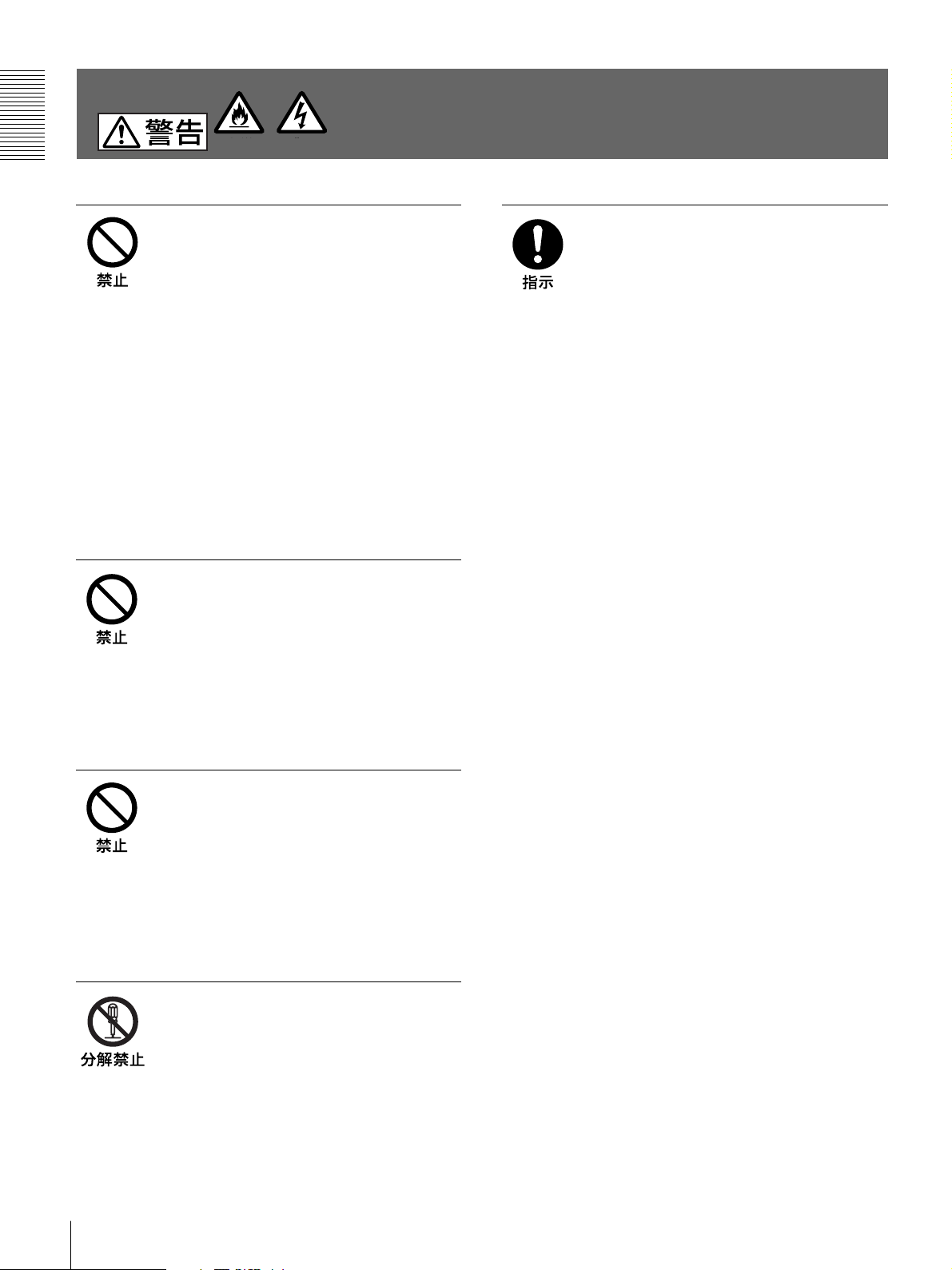
警告表示の意味
この取扱説明書および製品で
は、次のような表示をしていま
す。表示の内容をよく理解して
から本文をお読みください。
この表示の注意事項を守らない
と、火災や感電などにより死亡
や大けがなど人身事故につなが
ることがあります。
この表示の注意事項を守らない
と、感電やその他の事故により
けがをしたり周辺の物品に損害
を与えたりすることがありま
す。
万一、異常が起きたら
煙が出たら
•
異常な音、においが
•
したら
内部に水、異物が
•
入ったら
製品を落としたり、
•
キャビネットを破損
したときは
,
1 電源を切ります。
2 電源コードや接続ケーブルを抜
きます 。
3 お買い上げ店またはソニーの業
務用ご相談窓口までご相談くだ
さい。
注意を促す記号
行為を禁止する記号
行為を指示する記号
はじめに
2
目次/主な特長
目次
はじめに
主な特長 ..............................................................................
.............................................................................
............................................................................
準備
接続 .....................................................................................
本機を使用状況に合わせる .................................................
プリンター用紙トレー内にあるスライドスイッチを
切り換える ...................................................................
裏面パネルの
プリンター用紙について.....................................................
プリンター用紙を取り付ける ...........................................
操作
プリントする.....................................................................
プリントする ..............................................................
プリント画の向き/大きさを選ぶ .............................
明るさやコントラストを調節する .............................
リモコンを使ってプリントする .................................
その他
本機の性能を保持するために ...........................................
お手入れ ............................................................................
主な仕様 ............................................................................
故障とお考えになる前に...................................................
各部の名称と働き .............................................................
前面 ............................................................................
裏面 ............................................................................
保証書とアフターサービス ...............................................
保証書.........................................................................
アフターサービス.......................................................
スイッチを切り換える .....................
DIP
10
11
11
12
13
13
14
14
16
17
18
18
19
19
19
19
主な特長
静かな高画質プリント
• 高速ドライブIC内蔵の薄膜サーマルヘッドを採用。
3
4
5
6
6
6
7
9
12.8ドット/mmの高密度印画が可能になりました。
• 白黒256階調表現することができます。
• 温度差による印画ムラを防ぐ温度補正回路を内蔵しています。
簡単操作ですばやくプリント
• PRINTボタンを押すだけで、A7サイズ(STD、NORMモード時)
の高画質プリントが約3.9秒でできます。
• 同じ画面を最大11枚まで連続してプリントできます 。
画像方向、画像の大きさが切り換え可能
• 本体正面のスイッチで 、縦または横の画面方向を選択すること
ができます。
• 本体正面のつまみで、いろいろな印画画面の大きさを選択する
ことが で きます 。
ご使用になる状況に合わせた設定が可能
• ビデオ信号のすみずみまで印画可能。ビデオ信号の印画範囲
をNORM、WIDE1、WIDE2の3段階に切り換えることができま
す。
• 印画方向を、正方向(NORM)または逆方向(REV)に 切り換 える
ことが で きます 。
• 入力されるビデオ信号に応じて印画アスペクト比を4:3または1:
1に 切り換えることが できます 。
• プリンター用紙1枚あたりの印画枚数が多くとれるように、印画余
白を少なくする設定ができます。
NTSC/PAL
カラービデオ信号のNTSC、PAL、または白黒ビデオ信号のEIA、
CCIRいずれのビデオ信号が入力されても、自動的に判別してプ
リントします。どのビデオ信号でも同じ印画時間、印画サイズでプリ
ントします。
エラーを知らせるアラームブザー機能
エラーを知らせるアラームブ ザ ーにより、誤操作を防ぐことができま
す。
プリンター用紙の取り付けが簡単
ドアを開けて落とし込むだけで簡単にプリンター 用紙を 取り付ける
ことが で きます 。
ご注意
同梱以外の電源コードをご使用の際は、以下の表を参考に電取法
に適合した電源コードをご使用ください。
および
EIA/CCIR
ビデオ信号を自動判別
は
じ
め
に
JP
日
本
語
プラグタイプ VM1072
コネクター VM1289
コードタイプ HVCTF
定格 7A/125V
適合規格 電取法
はじめに
3
下記の注意を守らないと、
は
じ
め
に
火災 感電
火災や感電
により
電源コードを傷つけない
電源コードを傷つけると、火災や感電の原因と
なることが あります 。
• 設置時に、製品と壁やラック(棚)などの間
に、はさみこんだりしない
• 電源コードを加工したり、傷つけたりしない。
• 重いものをの せたり、引っ張ったりしない。
• 熱器具に近付けたり、加熱したりしない。
• 電源コードを 抜くときは、必ずプラグをもって
抜く。
万一、電源コードが傷んだら、お買い上げ店ま
たはソニーの業務用ご相談窓口に交換をご依
頼ください 。
油煙、湯気、湿気、ほこりの多い場
所には設置しない
死亡や大けが
本機は国内用です
交流100V でお使いください。
海外などで、異なる電圧で使うと、火災や感電
の 原 因 となることが あります 。
につながることがあります。
上記のような場所に設置すると、火災や感電の
原因となることがあります。
取扱説明書に記されている仕様条件以外の環
境での使用は、火災や感電の原因となることが
あります 。
内部に水や異物を入れない
水や異物が入ると火災や感電の原因となること
があります。
万一、水や異物が入ったときは、すぐに 電源を
切り、電源コードや接続コードを 抜い て、お買い
上げ店またはソニーの業務用ご相談窓口にご
相談ください。
内部を開けない
内部には電圧の高い部分があり、キャビネット
や裏蓋などを開けたり改造したりすると、火災
や感電の原因となることがあります。内部の調
整や設定、点検、修理は、お買い上げ店または
ソニーの業務用ご相談窓口にご依頼ください。
はじめに
4
下記の注意を守らないと、
けがをしたり周辺の物品に損害を与えることがあります。
ぬれた手で電源プラグをさわらない
カッターの刃には触れない
は
じ
め
に
ぬれた手で電源プラグを抜き差しすると、感電
の 原 因 となることが あります 。
接続の際は電源を切る
電源コードや接続コードを接続するときは、電源
を切ってください。感電や故障の原因となること
があります。
付属の電源コードを使う
付属の電源コードを 使 わないと、感電や故障の
原因となることがあります。
安全アースを接続する
安全アースを接続しないと、感電の原因となる
ことが あります 。
安全アースを取り付けることができない場合は、
お買い上げ店またはソニーの業務用ご相談窓
口にご相談ください。
不安定な場所に設置しない
ぐらついた台の上や傾いたところなどに設置す
ると、倒れたり落ちたりしてけがの原因となるこ
とがあります。
また、設置・取り付け場所の強度を充分にお確
かめください 。
製品の上に乗らない、重いものを載
せない
倒れたり、落ちたり、壊れたりして、けがの原因
とな ることが あります 。
カッターの刃に触れると、けがをすることがあり
ます。
本体内部に手を入れない
ドアが開いているときに、本体内部に手をいれ
ると、火傷および故障の原因となることがありま
す。
ドアの上に指を置かない
ドアを閉める際はドア の 上に指を置かない でく
ださい。
フロントパネルとの間に挟んでけがの原因とな
ることが あります 。
お手入れの際は、電源を切って電源
プラグを抜く
電源を接続したままお手入れをすると、感電の
原因となることがあります。
移動させるときは電源コード、接続
コードを抜く
接続したまま移動させると、コードが傷つき、火
災や感電の原因となることがあります。
通風孔をふさがない
通風孔をふさぐと内部に熱がこもり、火災や故
障の原因となることがあります。風通しをよくす
るために次の項目をお守りください 。
• 壁から10cm以上離して設置する。
• 密閉された狭い場所に押し込めない。
• 毛足の長い敷物(じゅうたんや布団など)の上
に設置しない。
• 布などで包まない。
• あお 向け や 横倒し、逆さまにしな い。
はじめに
5
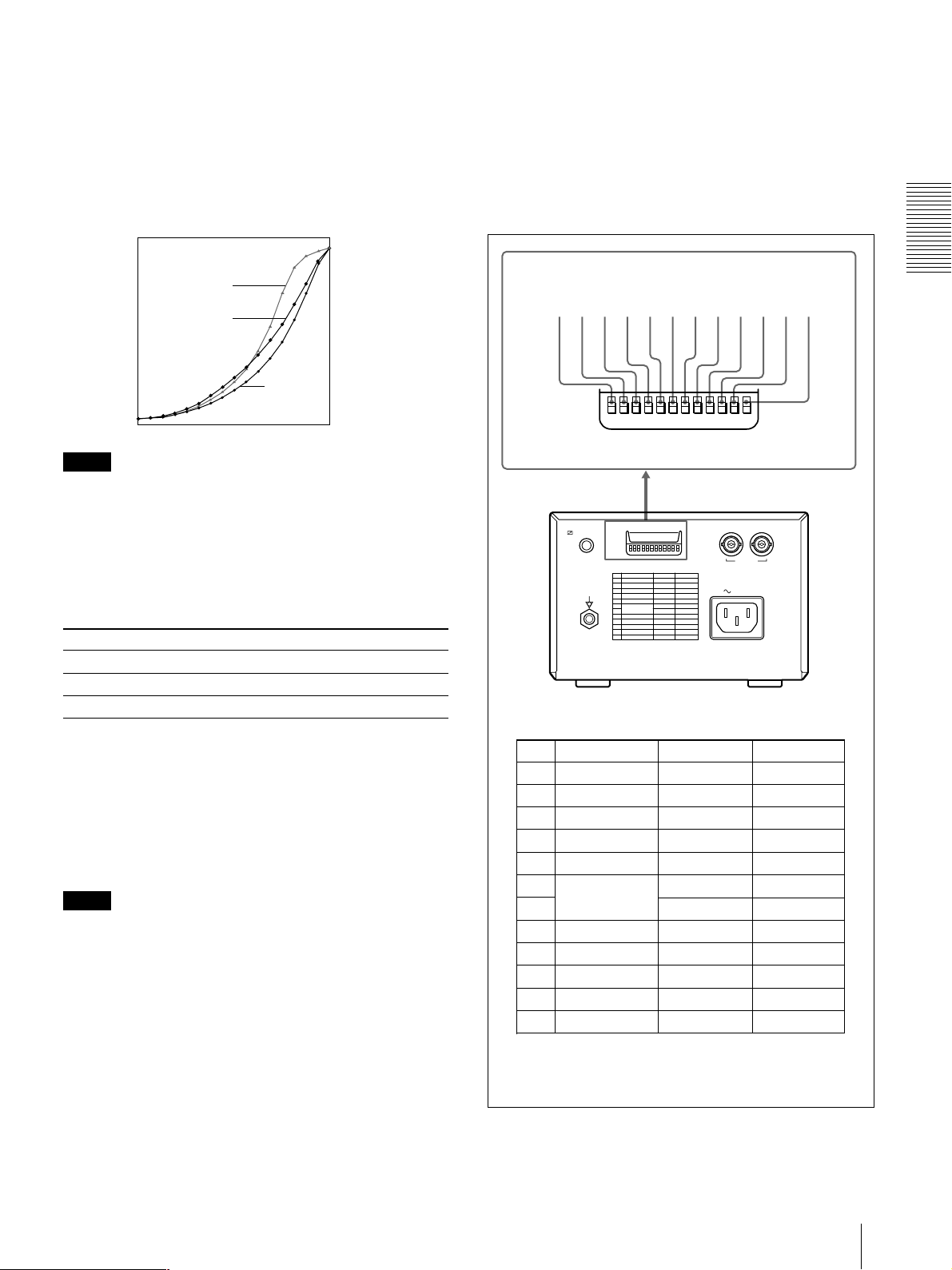
接続/本機を使用状況に合わせる
準
備
接続
• 各機器の電源を切ってから、接続してください。
• 電源コードは最後に接続してください。
ビデオ機器
カラー/白黒
ビデオ出力へ
付属の接続ケーブル
(
BNC y BNC
REMOTE
UP
DOWN
VIDEO IN
DIP SW
ビデオ入力へ
)
へ
t IN T OUT
VIDEO
モニター
接続ケーブル
(別売り)
VIDEO OUT
本機を使用状況に合わせる
2種類のスイッチを使って、本機を使用状況に合わせて設定できま
す。
• プリンター用 紙トレー内にあるスライドスイッチ
プリンター用紙の種類の設定、プリント画の画質の調節など使用
頻度の高い設定を行います。
• 裏面パネルにあるDIPスイッチ
比較的使用頻度の低い動作モード、プリンターの 仕 様 などを 設
定します。
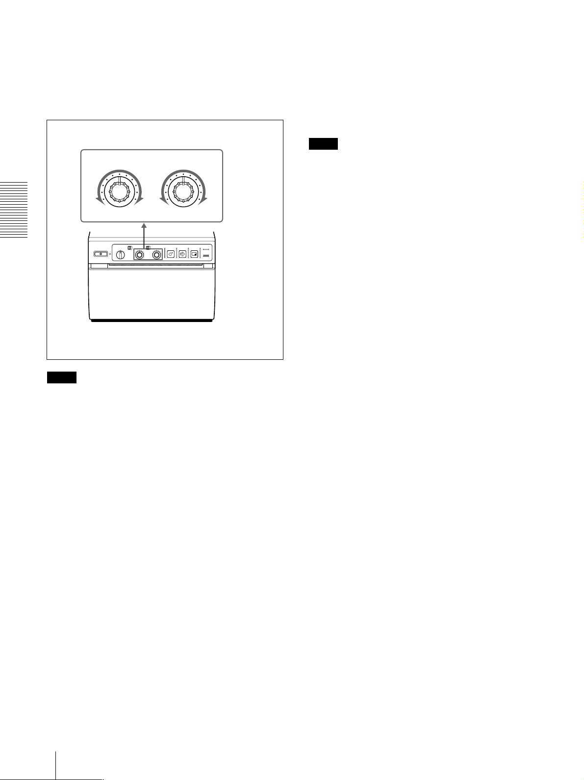
プリンター用紙トレー内にあるスライ ドスイッチを切り換える
下図は工場出荷時の各スイッチ の位 置を示します。
OFF OFF ON
ヘ
GAMMA
PAPER TYPE
HD HGS
1234
SMOOTHINGSHARPNESS
REMOTE
リモートコントロールユニット
(別売り)
RM-91
ヘ
AC IN
へ
AC IN
電源コード(付属)
電源コンセントへ
準備
6
本機を使用状況に合わせる
1
SHARPNESS
(シャープネス)切り換えスイッチ
プリント画の 輪 郭を強 調します。
:輪郭を強調しないプリント画が作成されます。
OFF
I、II、III:輪郭を強調させたいときに各位置に設定します。IIIに
いく程輪郭はより強調されます。
2
GAMMA
(ガンマ)切り換えスイッチ
印画のトーン(濃度階調特性)を、次のいずれかに切り換えます。
I: 軟調
II: 標準
III:硬調
各トーンのカーブは図のようになっています。
濃
III
II
印画濃度
I
淡
0 255
階調
裏面パネルの
スイッチを切り換える
DIP
下図は工場出荷時の各スイッチの設定位置を示します。
スイッチを切り換えるには
DIP
小さいドライバーの先などで切り換えてください。
123456789q;qaqs
DIP SW
UP
DOWN
REMOTE
DOWN
DIP SW
UP
121110987654321
t IN T OUT
VIDEO
準
備
ご注意
本機能は、プリンター用紙UPP-110HD、UPP-110HGを使用してい
る場合、すなわちPAPERTYPE切り換えスイッチ 3がIIまたはVに
設定されている場合のみ有効となります。
3
PAPER TYPE
(プリンター用紙)切り換えスイッチ
プリンター用紙の種類を設定します。
ご使用になる用紙の種類に合わせて、設定します。
用紙の種類 スイッチの位置
UPP-110S I (Normal=標準)
UPP-110HD II (HighDensity=高濃度)
UPP-110HG V (HighGlossy=高光沢)
4
SMOOTHING
(印画ライン密度)切り換えスイッチ
プリント画 の 印 画 ライン密 度を切り換えます 。
:通常はこの設定にします。
OFF
:プリント画 の 印 画ライン密度を高密度にし、なめらかな画質に
ON
します。ただし、OFFに比べてプリントの スピードが 遅くなります 。
ご注意
以下の場合のみ、本機能は有効となります。
• 前面のSTD/SIDE切り換えスイッチがSTDの位置に、裏面の
DIPスイッチのASPECT3が4:3に設定されている場合。
• 前面の画像サイズ選択つまみがSML、NOR以外の位置で、
STD/SIDE切り換えスイッチがSIDEの位置に、裏面のDIPスイッ
チのASPECT3が1:1に設定されている場合。
上記の場合以外は、本スイッチを ON の 位 置 にし ても印 画ラインは
高密度でプリントされませ ん。
DIP SW FUNCTION TABLE
NO.
FUNCTION
1
INTERRUPT
2
POSTFEED
3
ASPECT
4
MEMORY
5
DIRECTION
6
SCAN
7
8
OUTPUT
9
AGC
10
RESERVED
11
INPUT
12
75Ω
SW-DOWN、SW-UP
SW-DOWN
は下側に、
AC IN
SW-DOWN
ON
ON
4:3
FRAME
NORM
—
WIDE 1
THRU
OFF
—
B&W
ON
はスイッチの設定位置を表しています。
は上側に設定されています。
SW-UP
SW-UP
OFF
OFF
1:1
FIELD
REV
WIDE 2
NORM
EE
ON
—
COLOR
OFF
準備
7
本機を使用状況に合わせる
275
87654321
475
50
250
9
4
5
5
7
5
4
3
3
2
3
2
30
10
7
0
3
275
87654321
475
50
250
9
4
5
5
7
5
4
3
3
2
3
2
30
10
7
0
3
275
87654321
475
50
250
9
4
5
5
7
5
4
3
3
2
3
2
30
10
7
0
3
275
87654321
475
50
250
9
4
5
5
7
5
4
3
3
2
3
2
30
10
7
0
3
1
5
275
87654321
475
50
250
9
4
5
5
7
5
4
3
3
2
3
2
30
10
7
0
3
275
87654321
475
50
250
9
4
5
5
7
5
4
3
3
2
3
2
30
10
7
0
3
275
87654321
475
50
250
9
4
5
5
7
5
4
3
3
2
3
2
30
10
7
0
3
1
INTERRUPT
ON (SW-DOWN) :
プリントを中断し、PRINTボタンを押した瞬間の画像を新たにプリン
トします。
OFF (SW-UP) :
効になり、実行中のプリントを続けます。(ピーッとアラームブ ザ ーが
鳴ります 。)
(プリント中断)切り換えスイッチ
プリント中 にもう1度PRINTボタンを押すと、
プリント中 にもう1度 PR I N Tボタンを押し ても無
6 7
SCAN
(スキャンサイズ)切り換えスイッチ
プリントする画像の範囲を切り換えます。
NORM、WIDE1、WIDE2の順にプリントする範 囲 が 広くなります。
プリントする 画 像 の 範 囲を 切り換えるときは、DIPスイッチを下表の
ように 設 定し てください。
スキャンサイズ
スイッチ6
DIP
スイッチ7
DIP
NORM SW-DOWN SW-UP
WIDE1 SW-DOWN SW-DOWN
WIDE2 SW-UP SW-DOWN
ご注意
DIPスイッチ 6、DIPスイッチ 7の両方のスイッチをSW-UP(上側)
に設定することはお避けください 。
準
備
2
POSTFEED
(余白設定)切り換えスイッチ
プリントした後の余白の量を設定します。
ON (SW-DOWN) :
プリントした後に余白をつけて紙送りすると
き、この位置に設定します。
OFF (SW-UP) :
余白を少なくするとき、またはコピー機能を使用
して複数枚まとめてプリントを行う場合、この位置に設 定します。プ
リント画1枚あたりの余白が少ないので用紙1巻あたりのプリント画
枚数が多くとれます。ただし、ペーパーカット時 は 、FEEDボタンを押
して用紙を引き出してカットしてください。
3
ASPECT
(アスペクト)比切り換えスイッチ
通常は4:3にしておきます。アスペクト比が1:1の画面をプリントする
ときは 、1:1にします。
1
2
3
3
5
2
3
30
4
3
3
4
1 357 7 531
4
3
3
4
30
3
2
5
3
3
2
1
4 : 3
5
2
3
1
3
2
3
30
4
3
3
4
4
3
3
4
30
3
2
5
3
3
2
1
1
2
3
3
5
2
3
30
4
3
3
4
1 357 7 531
4
3
3
4
30
3
2
5
3
3
2
1
5
2
3
1
3
2
3
30
4
3
3
4
4
3
3
4
30
3
2
5
3
3
2
1
2
3
3
5
2
3
30
4
3
3
4
357 7 53
4
3
3
4
30
3
2
5
3
3
2
1
NORM
1
2
3
3
5
2
3
30
4
3
3
4
1 357 7 531
4
3
3
4
30
3
2
5
3
3
2
1
WIDE1
2
3
1
3
2
3
30
4
3
3
4
4
3
3
4
30
3
2
5
3
3
2
1
5
2
3
1
3
2
3
30
4
3
3
4
4
3
3
4
30
3
2
5
3
3
2
1
1
2
3
3
5
2
3
30
4
3
3
4
1 357 7 531
4
3
3
4
30
3
2
5
3
3
2
1
5
2
3
1
3
2
3
30
4
3
3
4
4
3
3
4
30
3
2
5
3
3
2
1
WIDE 2
1 : 1
4
MEMORY
FRAME (SW-DOWN)
FIELD (SW-UP)
間など)をプリントすると、画像がぶれて二重になることがあります。
このようなときはFIELDに設定します。
(メモリーモード)切り換えスイッチ
:通常はこの位置にしておきます。
:動きの速い画像(ボールがバットに当たる瞬
8
OUTPUT
(出力信号)切り換えスイッチ
裏面のVIDEOOUTコネクターからの出力信号を切り換えます。
THRU (SW-DOWN)
:VIDEOINコネクターに入力した信号
が信号処理の電気回路を通らずにそのまま出力されます。
EE (SW-UP)
:VIDEOINコネクターに入力した信号が信号処
理され て 出力されます 。
5
DIRECTION
印画方向を切り換えます。
NORM (SW-DOWN)
リントするときはこの位置に設 定します。
REV (SW-UP)
はこの位置に設定します。
1
2
3
3
5
2
3
30
4
3
3
4
1 357 7 531
4
3
3
4
30
3
2
5
3
3
2
1
8
NORM REV
準備
(プリント方向)切り換えスイッチ
:画像を正方向(画面の下から先)にプ
:逆方向(画面の上から先)にプリントするとき
5
2
3
1
3
2
3
30
4
3
3
4
4
3
3
4
30
3
2
5
3
3
2
1
1
2
3
3
5
2
3
30
4
3
3
4
4
3
3
4
30
3
2
3
1
3
2
5
1
2
3
3
5
2
3
30
4
3
3
4
1 357 7 531
4
3
3
4
30
3
2
5
3
3
2
1
また、75Ω切り換えスイッチqsの設定によらず、VIDEOIN端子の
インピーダンスは7 5 Ωになります。
9
AGC(Automatic Gain Control
)切り換えスイッチ
不適正なレベルの入力信号を、適切な入力レベルに補正します。
OFF (SW-DOWN)
ON (SW-UP)
:通常はこの位置に設定します。
:プリント画が全体的に白とび・黒つぶれを起こし
ているような場合には、この位置に設定します。
q;
RESERVED
スイッチ
通常は出荷状態(SW-DOWN)のままにしておいてください。

プリンター用紙について
qa
INPUT
B&W (SW-DOWN)
の位置に設定します。
COLOR (SW-UP)
の位置に設定します。
qs
75
ON (SW-DOWN)
ときは 、この 位 置に設 定します。
OFF (SW-UP)
ニターテレビまたは 他 のビデ オ 機 器に つなぐときは、この 位 置に 設
定します。
ただしOUTPUT切り換えスイッチ 8がEE(SW-UP)に設定されて
いる場合には、VIDEOIN端子のインピーダンスは7 5Ωに固 定され
ます。
例:
• 映像を出力する機器にプリンターとモ ニターテレビを 接 続 する場
合
−OFFにします。
• 映像を出力する機器に2台 の プリンターを接続する場合
−どちらか1 台をO N、残り1台をOF Fにします。
(入力信号)切り換えスイッチ
:印画するビデオ信号が白黒のときはこ
:印画するビデオ信号がカラーのときはこ
Ω(インピーダンス)切り換えスイッチ
:VIDEOOUTコネクターに何も接続しない
:VIDEOOUTコネクターからの出力信号をモ
プリンター用紙について
プリンター用紙は必ず専用のソニー
110HG
なると、プリントした画面の品質の保証ができないばかり
でなく、プリンターの故障の原因になります。
UP-880/890MD
UPP-110HA
をご使用ください。他のプリンター用紙をお使いに
で使用しているプリンター用紙
もご使用できませんのでご注意ください。
プリンター用紙の種類
UPP-110S/110HD/
プリンター用紙についてのご注意
使用する前のプリンター用紙を保管する場合:
下記の場所に保管してください。下記以外の場所に保管すると、プ
リンター用紙が変色することがあります。
• 30℃以下の冷暗な場所に保管してください。
• 湿度の低い、直射日光や室内光のあたらないところに保管して
ください。
• アルコールなどの揮発性有機溶剤やセロハンテープ、塩化ビ
ニールなどに触れない場所に保管してください 。
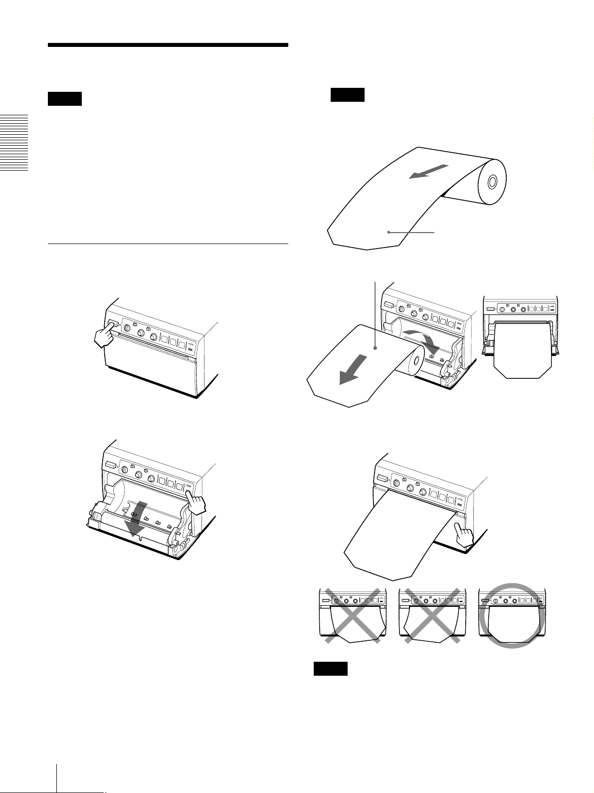
プリンター用紙を取り付ける場合:
• プリンター用 紙を 取り付ける 際 は、プリンター用紙の表面には触
れないでください 。指紋や汗、折り目 が つくと、印画ムラの原因に
なります 。
• プリンター用紙の先端に付いているラベルをはがしたら、必ず先
端の15〜20cmを引き出してください 。ラベルの跡が印画ムラの
原因になります。
プリントした用紙を保管する場合:
• プリントした用紙を保管するときは、下記の場所に保管してくださ
い。下記以外の場所に保管すると、プリンター用 紙が 変 色したり、
プリント画 面 が 薄くなること がありま す 。
− 30℃以下の冷暗な場所で、可塑材を含まない 紙 や、ポリプ
ロピレンの袋などにはさんで保管してください。
− 湿度の低い、直射日光や室内光のあたらないところに保管
してください。
− アルコールなどの揮発性有機溶剤やセロハンテープ、塩化
ビニールなどに触れない場所に保管してください 。
• ジアゾ式の湿式コピー(青焼)と重ねないでください。また、プリン
ト面どうしを重ねないでください 。プリンター 用 紙 が 変 色したり、プ
リント画 面 が 薄くなることが ありま す 。
• プリンター用 紙を 接 着 するときは、両面テープ、または水性のりを
ご使用ください。
準
備
プリンター用紙には次のような印画特性があります。
印画特性 用紙の種類
TYPEI (Normal=標準) UPP-110S
TYPEII (HighDensity=高濃度) UPP-110HD
TYPEV (HighGlossy=高光沢) UPP-110HG
プリンター用紙を廃棄する場合:
不燃物として廃棄してください。
準備
9
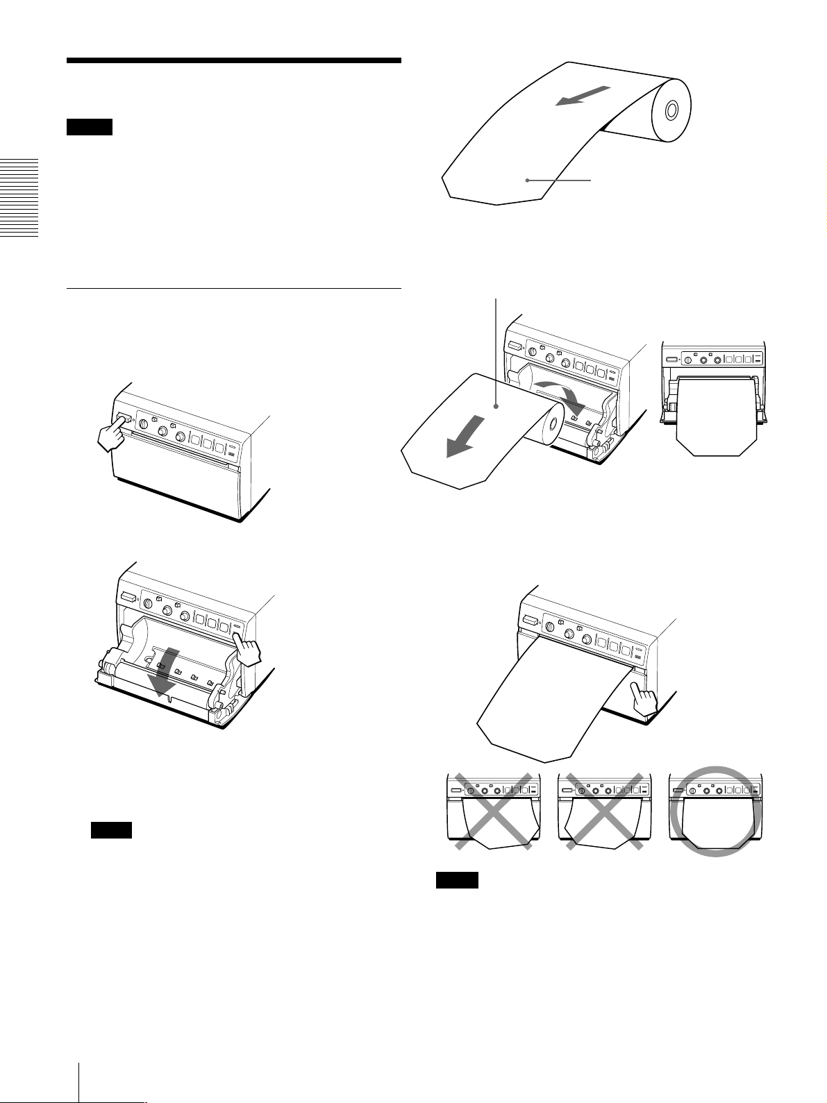
プリンター用紙を取り付ける
準
備
プリンター用紙を取り付ける
ご注意
• プリンター用 紙を 取り付ける 前 に、「プリンター用紙について」(9
ページ)をご 覧ください。
• プリンター用紙を入れる際は、プリンター用紙の表面には触れな
いでください。指紋や汗、折り目 がつくと、印 画ムラなど、プリントし
た画面の品質の低下につながります。
• プリンター用紙は専用のUPP-110S/110HD/110HG以外は使
用しな い でください。(9ページ)
• お使いになる用紙に合わせて、必ずPAPERTYPEスイッチを切
り換えてください。(7ページ)
取り付けるには
1 電源
ON/OFF
電源ランプが点灯します。
スイッチをONにし、電源を入れます。
3 プリンター用紙の先端に付いているラベルをはがし、
〜
れます。
ご注意
プリンター 用 紙を 引き出 すときや、トレー 内に 入 れ るときは 、プリ
ンター用 紙を 落とさないようお気を つ けください 。落としたりす
ると、ごみなどが付き、使用できなくなること が あります 。
感熱面を上にして入れる。
逆に入れるとプリントされ
ない。
程引き出してから、プリンター用紙トレーに入
20cm
ラベルをはがし、15〜
引き出す。
20cm
15
程
2
OPEN
プリンター用紙が
まっすぐになるよう
に入れる。
ボタンを押して、ドアを開けます。
4 ドアを手で押してしめます。
ご注意
• プリンター用紙が斜めに取り付けられていると、紙づまりなど の 原
因になります。
• 手順3でプリンター用紙を十分引き出さなかった場合は、プリン
ター用紙は引っ張らずに、前 面パネル のF E ED ボタンを押し
て、プリンター用紙を引き出してください 。
10
準備
プリントする
プリントする前に次のことを確認してください。
• 接続は正しいですか(6ぺージ)
• DIPスイッチ、スライドスイッチは正しく設定していますか?(6、7
ページ)
• プリンター用紙の種類は正しく設定していますか?(7ページ)
• プリンター用 紙は 正く取り付けてあります か?(10ページ)
• ビデオ信号が入力されていますか?
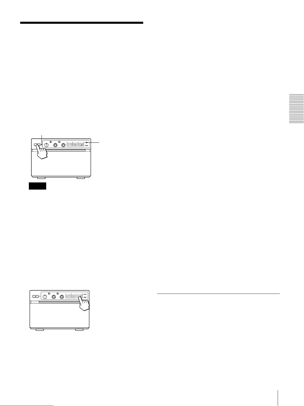
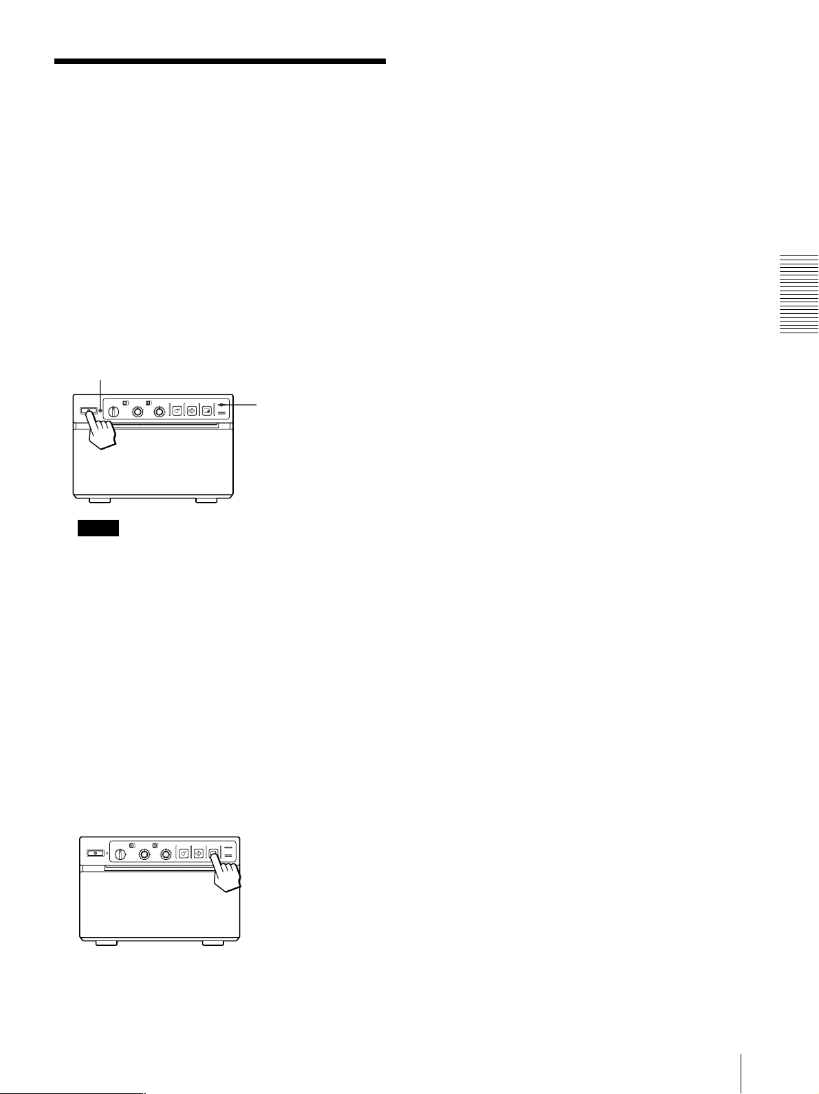
プリントする
1 電源
ON/OFF
電源ランプが点灯し、EMPTYランプが数秒間点滅します。
電源ランプ
スイッチをONにし、電源を入れます。
EMPTYランプ
プリントする
プリント画がぶれていたら
速く動いている画像を取り込むと、画像がぶれてしまうことが ありま
す。このとき、裏面のDIPスイッチ(MEMORY4)の設定をFIELD
に変えてプリントすることにより、プリント画からぶ れを 取り除くことが
できます。この場合、解像度が少し落ちます。
SMALL
前面の画像サイズ選 択つまみをS ML の位 置に設定 するとSMALL
モードでプリントできます 。このモードでは、異なる2つの画像を取り
込んで一度にプリントで きま す。
SMALL
を押してください。
1度押すとピッとブザーが鳴り、そのときの画 像 が 取り込まれます。
さらに 2 度 目を 押 すと、2枚目の画像が取り込まれてプリントが 始 ま
ります 。SMALLモードのプリント画について詳しくは次ページの
「プリント画の向き/大きさを選ぶ」をご覧ください。
プリンター用紙を引き出すには
FEEDボタンを押します。
FEEDボタンを押している間プリンター用 紙が 送り出されます 。
プリンター用紙は引っ張らないでください。
モードでプリントするとき
モードでプリントするには:手順4でPRINTボタン
操
作
ご注意
EMPTYランプが数秒間点滅後、消灯していることを確認しま
す。点灯している場合は、用紙がなくなっています。用紙を取
り付けてください。(「プリンター用 紙を 取り付 ける」10ページ)
2 プリント画の向きや大きさを選びます。
次ページの「プリント画 の向き/ 大きさを 選 ぶ 」をご 覧ください。
3 ビデオ機器などの入力源からの画像をモニターに映し出
します。
この操作は、ビデオ機器など接続した機器側で行います。
4 プリントしたい画像が映っているときに、
を押します。
押した瞬間の画面がプリントされます。
PRINT
ボタン
プリントした用紙を保管するときのご注意
• プリントした用紙を保管するときは、下記の場所に保管してくださ
い。下記以外の場所に保管すると、プリンター用紙が変色したり、
プリント画 面 が 薄くなる場合があります。
− 30℃以下の冷暗な場所で、可塑材を含まない紙や、ポリプ
ロピレンの袋などにはさんで保管してください。
− 湿度の低い、直射日光や室内光のあたらないところに保管
してください。
− アルコールなどの揮発性有機溶剤やセロハンテープ、塩化
ビニールなどに触れない場所に保管してください 。
• ジアゾ式の湿式コピー(青焼)と重ねない でください 。また、プリン
ト面どうしを重 ねな い でください 。プリンター用 紙が 変 色したり、プ
リント画 面 が 薄くなることが ありま す 。
• プリンター用紙を接着するときは、両面テープ、または水性のりを
ご使用ください。
プリンター用紙取扱のご注意について詳しくは、「プリンター用 紙に
ついて」(9ページ)をご 覧ください。
同じ画像をもう1度プリントするには
COPYボタンを押します。最後にプリントした画 像と同じものがプリ
ントされます。最後にプリントした画像はプリンター内部に記憶され
ており、この画像は他の画像をプリントするか 、プリンターの 電 源 を
切るまで、残っています。
プリントを中断するには
プリント中またはコピー中に、OPENボタン、またはFEEDボタンを押
すとプリント動 作 は 止 まります 。
プリントを中断して現在映っている画像をプリントするには
裏面のDIPスイッチ(INTERRUPT1 )が ONになって いる状態
(8ページ)で、プリント中またはコピー中にPRINTボタンを押します。
プリントは 中
ントされます。
断され、PRINTボタンを押した瞬間の画像が新たにプリ
画像の向き/大きさを変えてコピーするには
最後にプリントした画 像を違う向き/大きさでコピーすることが でき
ます。「プリント画の向き/ 大きさを選ぶ」で向き/大きさを選んでか
ら、COPYボタンを押します。
操作
11
プリントする
操
作
ご注意
• 電源を入れた直後など、プリンターに画像が記憶されていない
状態でCOPYボタンを押すと、アラームブザ ーが 鳴り、コピ ーでき
ません。
• SMALLモードで、1度しかPRINTボタンを押していない状態で
COPYボタンを押すと、アラームブ ザーが 鳴り、コピ ー で きま せ ん 。
同じ画像を連続してコピーするには
PRINTボタンまたはCOPYボタンを押して1枚目をプリント中 に
COPYボタンを押します。COPYボタンを押した時にブ ザーがピッと
鳴り、COPYボタンを押した数だけ(最初の1枚を含めて最大11枚)
連続コピーできます。
途中で止めるには
OPENボタン、またはFEEDボタンを押します。
プリント画の向き/大きさを選ぶ
STD/SIDE切り換えスイッチ、画像サイズ選択つまみ、DIPスイッチ
により、色々なプリント画を 作 ることが できます。
プリント画の向きを選ぶには
STD/SIDE切り換えスイッチで 、標準向きか横向きかを選ぶことが
できます。
画像をモニター画面に映し出されている向きでプリントする
とき:STD(標準)側にします。
画像を横向きにするとき:SIDE(横)側にします。
色々なプリント画を作るには
画像サイズ選択つまみ、
STD/SIDE
定で作成するプリント画
下の表は、画像サイズ選択つまみとSTD/SIDE切り換えスイッチ
の設定の組み合わせにより作成できるプリント画を表しています。
NOR
SML 2×
つまみの位置
(詳細)
NOR
(NORMAL)
SML
(SMALL)
R/T
(RIGHT/
TOP)
R/T
L/B
BOTH
画像の大きさ
側
STD
切り換えスイッチの設
STD
SIDE
SIDE
側
STD
SIDE
STD
モニター画面に映し出されている画像
プリント画
側に設定されている場合
STD
SIDE
る場合
プリント画の大きさを選ぶには
SIDE
L/B
(LEFT/
BOTTOM)
側に設定されてい
BOTH
画像サイズ選択つまみで画像を拡大したり、縮小したりすることが
できます。また、画面の左右、上 下を2 倍に拡大することができます。
つまみを希 望 の大きさに合 わ せます。
操作
12

プリントする
白黒反転のプリント画を作るには
本機前面のPOSI/NEGAスイッチをNEGAの位置に設定します。
明るさやコントラストを調節する
本機前面のCONTRつまみ/BRIGHTつまみを使ってプリント画
の明るさとコントラストを調節できます。
CONTR BRIGHT
ご注意
メモリーに取り込まれた画像の明るさやコントラストを 変えることは で
きませ ん。明るさやコントラストを変更したいときは、PRINTボタンを
押して 画 像をメモリーに取り込 む 前に 調 節し てください。
リモコンを使ってプリントする
本機裏面のREMOTE端子に接続したリモートコントロール ユニット
RM-91、またはフットスイッチを使ってプリント操 作 をリモ ートコ ント
ロール できます。
リモコン の スイッチを 押 すと、メモリーに画 像 が 取り込まれ、プリント
されます。
本機裏面のDIPスイッチのINTERRUPT1をONに設定しておく
と(8ページ)、プリント中 、またはコピー中にリモコンのスイッチを 押
すと、プリントは中断され、スイッチを押した瞬間の画像が新たにプ
リントされます 。
操
作
ご注意
調節した画像をモニター画面上で確認しながら明るさやコントラス
トを調節するには、裏面
します。
調節が終わったらDIPスイッチをTHRU側に設定し直してくださ
い。THRU側に設定すると、ビデオ信号はプリンターの電気回路を
通らず、そのままモニターに入力されます。
プリンターにつないでいるビデオ機器からのビデオ信号を直接モ
ニターできます。
コントラストを調節するには
プリンター前面のCONTRつまみを使って調節します。
コントラストを強くするには:CONTRつまみを時計方向に回
します。
コントラストを弱くするには:CONTRつまみを反時計方向に
回します。
明るさを調節するには
プリンター前面のBRIGHTつまみを使って調節します。
明るくするには:BRIGHTつまみを時計方向に回します。
暗くするには:BRIGHTつまみを反時計方向に回します。
スイッチの
DIP
OUTPUTをEE
に設定
操作
13
本機の性能を保持するために/お手入れ
そ
の
他
本機の性能を保持するために
電源について
• 電源はAC100Vをお使いください。
• 電源コードは傷つけないでください 。
• 長い間使わないときは、電源コードを 抜 い て お い てください。
• 電源コードを抜くときは 、電源プラグを持って抜 いてください。
安全のために
• キャビネットは絶対に開けないでください。内部に触 れると危険
です。
• 内部にものを落とさないでください 。
• ペーパーカッターには触れないでください 。
置き場所について
• 水平な場所に置いてください 。傾けた状態で本機を使用すると、
故障の原因となります。
• 暑い所や湿気の多い所に置かないでください 。
• 湿気の低い冬場では、湿度35%以上の環境で使うことを お す す
めしま す 。
• 結露にご注意ください 。
温度の低い場所から暖かい場所に移動したり、暖房で湯気や湿
気がたち込めた部屋に置くと、本機の内部に水滴がつくことが あ
ります。これを 結 露といいます。この状態で本機を使用すると、正
常に動かないばかりでなく、故障の原因になります。結露の可能
性 の あるときは 、電源を切り、しばらくそのまま放置してください。
お手入れ
キャビネットのクリーニング
キャビネットの汚れは、水または水で薄めた中性洗剤溶液で湿らせ
た布をかたくしぼってから、拭き取ってください。シン ナ ー や ベンジ
ン、アルコールなどは表面の仕上げを傷めることがあります ので、使
用しな い でください。
ヘッドのクリーニング
プリント画に白いスジが生じたら、付属のヘッドクリーニングシートで
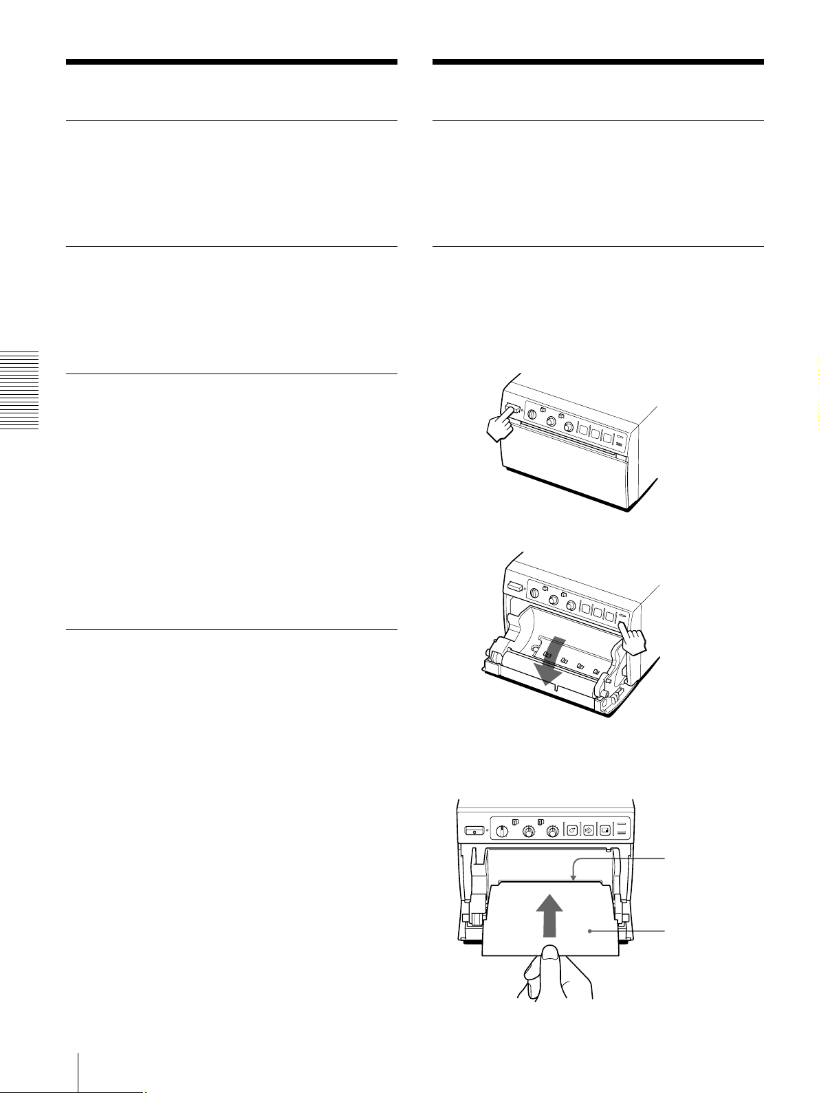
ヘッドをきれ いにし てください。
1 電源
2
OPEN
ON/OFF
スイッチをONにし、電源を入れます。
ボタンを押し、ドアを開けます。
持ち運びについて
• ぶつけたり、落としたりしないように気をつけてください。
• 持ち運びの際は、プリンター用紙を取り外してください。プリンター
用紙を取り付けたまま持ち運ぶと故障の原因になることがありま
す。
3 付属のヘッドクリーニングシートの黒い面を下にして、
トレー内のスライドスイッチの上にある窪みに差し込み
ます。
トレー内の
スライドスイッチの
上にある窪みに差し
込む
付属のヘッド
クリーニングシート
14
その他
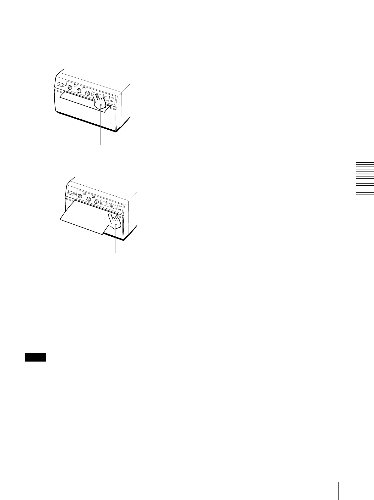
4 ドアを手で押して閉めます。
お手入れ
5
ボタンを、クリーニングシートが排出され始める
FEED
まで押し続け、ブザーが鳴ったら離します。
FEEDボタンを押し続ける
x
そ
の
他
ピピピとブザーが
鳴ったら離す。
クリーニングが終了します。
6
OPEN
シートを取り除きます。
ボタンを押し、ドアを開けヘッドクリーニング
7 ドアを手で押して閉めます。
ご注意
ヘッドクリーニングシートは必要に応じてお使いください 。ヘッドのク
リーニングを頻煩に行うと、故障の原因になることがあります。
その他
15
そ
の
他
主な仕様
主な仕様
感熱ヘッド薄膜サーマルヘッド(ドライブIC内蔵)1280ドット
階調数 256階調
解像度(WIDE1のとき)
EIA:1210×490ドット
CCIR:1210×582ドット
画面寸法(画像サイズ:NOR、WIDE1のとき)
STDモード
EIA:94×72mm
CCIR:9 4 × 7 1mm
SIDEモード
EIA:126×96mm
CCIR:126×95mm
プリ ント速 度 約3.9秒/1画面
(出荷設定時)
ピクチャ ーメモ リ ー
1フ レ ーム(800k×8bit相当)
入力端子 VIDEOIN(BNC)
EIAまたはCCIR方式コンポジットビデオ信号:
1.0Vp-p、75Ω/ハイインピーダンス切り 換え
方式(EIA/CCIR自動判別方式)
出力端子 VIDEOOUT(BNC)
EIAまたはCCIR方式コンポジットビデオ信号:
1.0Vp-p、75Ωループス ルー/EE切り換え方
式
リモート端子 REMOTE(ステレオミ ニジ ャ ッ ク)
端子仕様
最大外形寸法 154×105×260mm(幅/高さ/奥行き)
質量 3.4kg(本体のみ)
付属品 プリンター用 紙(UPP-110HG)(1)
BNCyBNCケーブル(1)
AC電源コード(1)
3Py2P AC変換アダプター(1)
ヘッドクリーニングシート(1)
取扱説明書(1)
サー ビス窓口のしおり・ご相談窓口の
ご案内(1)
保証書(1)
メディ アラベ ル(1)
本機の仕様および外観は、改良のため予告なく変更することが
あります が、ご了承ください。
本機は高調波電流規格「JISC61000-3-2適合品」です。
3
2
1
1 GND
2PRINTSIGNAL(TTL)
100msec以上LOWのパルスが入力されると
プリ ントが開始されます。
3 PRINTBUSY(TTL)
プリ ント中はHIGHレベルになります。
動作温度 5℃〜35℃
動作湿度 20%〜80% (結露無きこと)
電源 AC100V、50/60Hz
消費電力 20W(スタンバイ時)
120W(プリント時 )
最大1.5A
16
その他

故障とお考えになる前に
故障とお考えになる前に
修 理 にお 出しになる前 にもう一度 点 検し てください 。それでも正常
に動作しないときは、お買い上げ店またはソニーの業務用ご相談
窓口にお問い合わせください。
こんなときは
細かいゴミが最初に
プリントした数枚に現
れる。
PRINTボタンを押し
てもプリントできな い。
ご確認ください
プリンター用 紙を 交 換した ばかりではありませ ん か?
tFEEDボタンを押して、紙を15〜20cm引き出してか
らプリントしてください。(10ページ)
• プリンター用紙が送られない場合
t電源は入っていますか?
t正しく接続されていますか?
tプリンター用紙がたるんでいませんか?
tSMALLモードのとき、2度PRINTボタンを押しまし
たか?(11ページ)
• アラームブザーが鳴った場合
tサーマルヘッドが温度上昇していませんか?真 っ
黒に近い画像を連続してプリントすると、サーマル
ヘッドの温度が上昇する場合があります。この 場
合、EMPTYランプが点滅しています。しばらくプリ
ントをやめてください 。
tビデオ信号は入力されていますか?
tプリンター 用 紙は 正しく取り付け てあります か?
• プリンター用紙は送られるがプリントされない場合
t用紙の感熱面を上にして取り付けましたか?(10
ページ)
全面が真っ黒に近い
画像を連続してプリン
トし たら、プリントしなく
なっ てしまった 。(ア
ラームブザーが 鳴る。)
白い線や小さい文字
がぼけたり、二重に
なって見える。
全体に細かいチェック
模 様 が 見える。
プリント画が 明るすぎ
る、または 暗 すぎる。
プリントされた画面が
細長い。
真っ黒に近い画像を15枚以上プリントすると、それ以 上
プリントしなくなることがあります。
tサーマルヘッドの温度上昇を抑えるために保護回
路が動作しているためです。しばらくプリントをやめ
てください。
白黒ビデオ信号に対して、INPUT切り換えスイッチ
(DIPスイッチ の qa)がCOLORになっていませんか?
(8ページ)
カラービデ オ信 号 に対して、INPUT切り換えスイッチ
(DIPスイッチ のqa)がB&Wになっていません か?(8
ページ)
・75Ω切り換えスイッチ(DIPスイッチ の qs)は正しく設
定してありますか?(8ページ)
・プリンター 用 紙トレー内のPAPERTYPEスイッチ は
正しく設 定し てあります か?(7ページ)
・プリンター用 紙トレー内のGAMMAスイッチは 正しく
設定してありますか?(7ページ)
ASPECT切り換えスイッチ(DIPスイッチ の3)が1:1に
なっていませんか?
t4 : 3に設 定してください。(8ページ)
そ
の
他
プリント画 の 周 囲 に 黒
い線ができる、または
周囲が欠けている。
紙詰まりが起きた。
印画ムラが起きる。
ビデオ信号によっては周囲に黒い線ができたり、周囲
が欠けたりすることがあります。SCAN切り換えスイッチ
(DIPスイッチ の 67)を 切り換えてください。(8ページ)
• OPENボタンを押してドアを開け、プリンター用 紙を 取
り出して から、詰まった紙を手でゆっくり引き出してく
ださい。
• プリンターが結露していませんか?
寒い所から急に暑い所にプリンターを移 すと、内部に
水滴がつくこと(結露)があります。結露したら電源を
切ったまま1〜2時間放置してください。
ヘッドが汚れていませんか?
t付属のヘッドクリーニ ン グ シ ートを使って、ヘッドをき
れいにしてください 。(14ページ)
その他
17
各部の名称と働き
各部の名称と働き
( )内の数字は参照ページを示します。
前面
1 電源
ON/OFF
スイ ッチをO Nにして電源を入れると、ランプ が点灯します。
スイッチとランプ
そ
の
他
前面
1 23456 7 8 9 q; qa qs
STD
POSI
NOR
SML 2×
R/T
L/B
BOTH
SIDE NEGA
CONTR BRIGHT
FEED COPY PRINT
EMPTY
OPEN
2 画像サイズ選択つまみ(
12
)
プリ ントする画像の大きさを選択します。
3
STD/SIDE
(標準/横)切り換えスイッチ(12)
標準の向きにプリ ントするか 横 向きにプリントするかを選択し
ます。
4
CONTR
(コントラスト)つまみ(13)
プリ ント画 のコン トラス トを調節します。
5
POSI/NEGA
(白黒反転)切り換えスイッチ(13)
白黒反転したプリント画を作成するときNEGAの位置にしま
す。
6
BRIGHT
(明るさ)つまみ(13)
プリ ント画 の 明暗を調節します。
7
(紙送り)ボタン(10、11、12、15)
FEED
用紙を送るとき押します 。 押している間だけ用紙が送られま
す。プリント中 に押すと、プリ ントが中止されます。
8
(複写)ボタン(11、12)
COPY
最後にプ リントした画像を再度プリントするときに押します。
裏面
12 345
REMOTE
DOWN
DIP SW
UP
t IN T OUT
VIDEO
AC IN
9
(プリント)ボタン(11)
PRINT
モニ ター上に表示されてい る画像をプリントするときに 押しま
す。PRINTボタンを押した瞬間の画像はメモリーに記憶され
ます。
q;
EMPTY
(紙無し)ランプ(11)
プリ ンター用 紙が 無くなっ たときに点灯し ます。
18
その他
各部の名称と働き/保証書とアフターサービス
qa
(開)ボタン(10、14)
OPEN
ドアを開けるときに押します。プリント中 に 押 すとプリントを中断
できます。
OPENボタンを押すと、プリンター用 紙トレー内 のスライドスイッ
チが現れます。
OFF OFF ON
GAMMA
PAPER TYPE
HD HGS
SMOOTHINGSHARPNESS
1234
1 SHARPNESS(シャープ ネス)切り換えスイッチ
プリント画の 輪 郭を強 調します。
2 GAMMA(ガンマ)切り換えスイッチ
印画のトーン(濃度階調特性)を切り換えます 。
3 PAPERTYPE(プリンター用 紙 )切り換えスイッチ
プリンター用紙の種類を設定します。
4 SMOOTHING(印画ライン密度)切り換えスイッチ
プリント画 の 印 画 ライン密 度を切り換えます 。
保証書とアフターサービス
保証書
この製品には保証書が添付されていますので、お買い上げの際お
受け取りください 。所定事項の記入および記載内容をお確かめの
うえ、大切に保存してください。
アフターサービス
調子が悪いときはまずチェックを
この説明書をもう一度ご覧になってお調べください。
それでも調子の悪いときはサービスへ
お買い上げ店、または お近くのソニーサービス窓口にご相談くださ
い。
保証期間中の修理は
保証書の記載内容に基づいて修理させていただきます。詳しくは
保証書をご覧ください 。
そ
の
他
各スイッチの機能について詳しくは、6 ページをご 覧ください。
qs プリント画出口/カッター
プリント画を出口でカットするための刃がついています。
裏面
1
2
3 t
4 y
REMOTE
別売りのリモートコントロールユニットRM-91、またはフットスイッ
チをつなぎます。
DIP SW
プリンターのビデオ信号処理モードや印画モードを 設 定しま
す。
VIDEO IN
ビデオ機器のビデオ(映像)出力につなぎます。
VIDEO OUT
モニターのビデオ(映像)入力につなぎます。VIDEOIN端子
から入力した信号またはプリンターで信号処理をした信号が
出力されます。出力する信号の種類は、裏面のDIPスイッチ
8(OUTPUT)の設定により決まります。
(リモコン)端子(6、13)
(ディップスイッチ)(7)
(ビデオ入力)端子(6)
(ビデオ出力)端子(6)
保証期間経過後の修理は
修理によって機能が維持できる場合は、ご要望により有料修理さ
せていただきます。
部品の保有期間について
当社では、ビデオグラフィックプリンターUP-895/895MDの補修用
性能部品(製品の機能を維持するために必要な部品)を、製造打
ち切り後最 低 10 年保 有しています。この部品保有期間を修理可能
の期間とさせていただきます。保有期間が経過した後も、故障箇所
によっては、修理可能の場合がありますので、お買い上げ店か、
サービス窓口にご相談ください。
5 -
付属の電源コードを差し込みます。
(電源)端子(6)
AC IN
その他
19
English
WARNING
To prevent fire or shock hazard, do not expose the unit to
rain or moisture.
To avoid electrical shock, do not open the cabinet. Refer
servicing to qualified personnel only.
THIS APPARATUS MUST BE EARTHED.
For UP-895MD/895CE
Symbol on the products
This symbol indicates the equipotential
terminal which brings the various parts of a
system to the same potential.
This symbol is intended to alert the user to
the presence of important operating and
maintenance (servicing) instructions in the
literature accompanying the appliance.
For the customers in the U.S.A.
(for UP-895/895MD)
This equipment has been tested and found to comply with
the limits for a Class A digital device, pursuant to Part 15 of
the FCC Rules. These limits are designed to provide
reasonable protection against harmful interference when the
equipment is operated in a commercial environment. This
equipment generates, uses, and can radiate radio frequency
energy and, if not installed and used in accordance with the
instruction manual, may cause harmful interference to radio
communications. Operation of this equipment in a
residential area is likely to cause harmful interference in
which case the user will be required to correct the
interference at his own expense.
You are cautioned that any changes or modifications not
expressly approved in this manual could void your authority
to operate this equipment.
This device requires shielded interface cables to comply
with FCC emission limits.
For the customers in Canada
(for UP-895MD)
This unit has been certified according to Standard CSA
C22.2 NO.601.1.
For UP-895MD/895CE
Important safeguards/notices for use in the
medical environments
1. All the equipments connected to this unit shall be certified
according to Standard IEC601-1, IEC950, IEC65 or other
IEC/ISO Standards applicable to the equipments.
2. When this unit is used together with other equipment in
the patient area*, the equipment shall be either powered
by an isolation transformer or connected via an additional
protective earth terminal to system ground unless it is
certified according to Standard IEC601-1.
* Patient Area
R1.5m
3. The leakage current could increase when connected to
other equipment.
4. This equipment generates, uses, and can radiate
frequency energy. If it is not installed and used in
accordance with the instruction manual, it may cause
interference to other equipment. If this unit causes
interference (which can be determined by unplugging the
power cord from the unit), try these measures: Relocate
the unit with respect to the susceptible equipment. Plug
this unit and the susceptible equipment into different
branch circuit. Consult your dealer. (According to
Standard EN60601-1-2 and CISPR11, Class B, Group 1)
Caution
When you dispose of the unit or accessories, you must obey
the law in the relative area or country and the regulation in
the relative hospital.
Warning on power connection for medical use
Please use the following power supply cord.
With connectors (plug or female) and cord types other than
those indicated in this table, use the power supply cord that is
approved for use in your area.
United States Canada
Plug Type HOSPITAL GRADE* HOSPITAL GRADE*
Female end E62405, E35708 LR53182, LL022442,
LL088408
Cord type E159216, E35496 LL112007-1, LL20262,
Min.Type SJT LL32121, LL84494
Min.18AWG Min.Type SJT
Min.18AWG
Minimum cord 10A/125V 10A/125V
set rating
Safety approval UL Listed CSA
20
*Note: Grounding reliability can only be achieved when the
equipment is connected to an equivalent receptacle
marked ‘Hospital Only’ or ‘Hospital Grade’.
Introduction

Table of Contents/Overview
Table of Contents
Introduction
Overview ................................................................. 21
Prepration
Connection.............................................................. 22
Setting Up the Printer ........................................... 22
Setting the Slide Switches on the Paper Tray..... 22
Setting the DIP Switches on the Rear Panel....... 23
Paper ....................................................................... 25
Loading Paper ........................................................ 26
Operation
Printing ................................................................... 27
Making Printouts ................................................ 27
Selecting the Printing Direction/Image Size ...... 28
Adjusting the Contrast and Brightness ............... 30
Remotely Controlling the Printer ....................... 30
Others
Precautions ............................................................. 31
Maintenance ........................................................... 31
Specifications.......................................................... 32
Troubleshooting ..................................................... 34
Location and Function of Parts ............................ 35
Front ................................................................... 35
Back .................................................................... 36
Overview
The UP-895/895MD/895CE is a black and white video
graphics printer that can be used to print images
displayed on a video monitor.
This manual covers the UP-895/895MD/895CE models.
Wherever the operation or any other item differs among
the models, this manual clearly describes those
differences.
Clear, consistent print quality
• High definition, 12.8 dots/mm printing using a thermal
head with a high-speed drive IC.
• 256 gradations of black and white.
• Stable printouts using temperature compensation
technology
Fast printing
• You can make an A-7 size single printout in about 3.9
seconds in STD and NORM mode.
• You can make a maximum of 11 copies of the same
image continuously.
Two way printing direction and various image
sizes
• The printing direction selector on the front panel
enables you to print in vertical and horizontal
directions.
• The image size selector on the front panel enables you
to select various printing size.
DIP switches and slide switches to optimize
the printer
• You can adjust printout quality and select the paper
type by setting the slide switches.
• You can make printouts starting either from the bottom
or top of the image by setting the DIRECTION of DIP
switch.
• You can set the printout aspect ratio to 4:3 or 1:1 by
setting the ASPECT of DIP switch.
• You can set the range to be printed by setting the
SCAN DIP switch.
• You can save paper by setting the POSTFEED DIP
switch (paper saving function).
Introduction
GB
English
Automatic video signal determination
The type of input signal, black and white (EIA or CCIR)
or input color (NTSC or PAL), is automatically
determined and printed in the same duration and size.
Alarm buzzer
The alarm buzzer prevents you from making any
mistakes.
Easy and quick paper loading
You can load paper just by opening the door and placing
the paper roll.
Introduction
21
Connection/Setting Up the Printer
Connection
Notes
• Turn off the power to each device before making any
connections.
• Connect the AC power cord last.
Preparation
Video equipment
Color/black and
to video output
connector
Supplied coaxial connecting
cable (BNC y BNC)
white video monitor
to video input
connector
Connecting cable
(not supplied)
Setting Up the Printer
You can set the printer to the desired specifications using
two kinds of switches.
• Slide switches on the paper tray inside the front door
You can easily set the printer specifications most
frequently used in daily operation, such as selection of
the paper type and printout quality.
• DIP switches on the rear panel
You can set the print mode and other settings you do
not need to change frequently
Setting the Slide Switches on the Paper Tray
The factory settings are as follows.
OFF OFF ON
GAMMA
PAPER TYPE
SMOOTHINGSHARPNESS
to VIDEO IN
REMOTE
RM-91 Remote control unit
(not supplied)
DIP SW
UP
DOWN
to REMOTE
t IN T OUT
VIDEO
AC IN
to AC IN
Supplied AC
power cord
to VIDEO OUT
to wall outlet
HD HGS
1234
A SHARPNESS switch
Adjusts the sharpness of the printout.
OFF: Not to emphasize an outline of the printout, set
the switch to this position.
I, II, III: To make a sharper outline, set the switch to
the proper position. In I, II and III order, the printout
becomes sharper.
22
Preparation
Setting Up the Printer
B GAMMA switch
Sets the tone of printouts (density gradation).
I: Soft gradation
II: Standard
III: Hard gradation
The diagram below shows the curve of density
graduation for each tone.
High
I
II
Print density
III
Note
Low
0
Gradation
255
This switch is effective only when you use paper types
UPP-110HD or UPP-110HG, that is, when the PAPER
TYPE switch C is set to either II or V.
C PAPER TYPE switch
Selects the paper type.
Set the switch to the type of paper to be used.
Setting the DIP Switches on the Rear Panel
To change the DIP switch settings
Use a small pointed tool such as a small screwdriver.
The factory settings are as follows.
123456789q;qaqs
DIP SW
UP
DOWN
REMOTE
DOWN
DIP SW
UP
121110987654321
t IN T OUT
VIDEO
AC IN
Preparation
Type of paper Switch position
UPP-110S I (Normal)
UPP-110HD II (High density)
UPP-110HG V (High glossy)
D SMOOTHING switch
Selects the line density.
OFF: Normally keep this switch to this position.
ON: To set the print line density to high density and
obtain the better print quality, set the switch to this
position. However, the printing speed is slower than at
the OFF position.
Note
This switch becomes effective under the following
conditions.
• When the STD/SIDE selector on the front panel is set
to STD, and ASPECT of DIP switch 3 on the rear
panel is set to 4:3.
• When the image size selector on the front panel is set
to a position other than SML and NOR and the
STD/SIDE selector is set SIDE, and ASPECT of DIP
switch 3 is set to 1:1.
Under any other conditions except those above, the print
line density is not set to high even if you set the switch
to ON.
UP-895MD/895CE
DIP SW FUNCTION TABLE
NO. FUNCTION SW-DOWN SW-UP
1 INTERRUPT ON OFF
2 POSTFEED ON OFF
3 ASPECT 4:3 1:1
4 MEMORY FRAME FIELD
5 DIRECTION NORM REV
6 SCAN – WIDE 2
7 WIDE 1 NORM
8 OUTPUT THRU EE
9 AGC OFF ON
10 RESERVED ––
11 INPUT B & W COLOR
12 75 Ω ON OFF
SW-DOWN or SW-UP indicated in parentheses
shows the switch position.
Preparation
23
275
87654321
475
50
250
9
4
5
5
7
5
4
3
3
2
3
2
30
10
7
0
3
275
87654321
475
50
250
9
4
5
5
7
5
4
3
3
2
3
2
30
10
7
0
3
275
87654321
475
50
250
9
4
5
5
7
5
4
3
3
2
3
2
30
10
7
0
3
275
87654321
475
50
250
9
4
5
5
7
5
4
3
3
2
3
2
30
10
7
0
3
1
5
275
87654321
475
50
250
9
4
5
5
7
5
4
3
3
2
3
2
30
10
7
0
3
275
87654321
475
50
250
9
4
5
5
7
5
4
3
3
2
3
2
30
10
7
0
3
275
87654321
475
50
250
9
4
5
5
7
5
4
3
3
2
3
2
30
10
7
0
3
Setting Up the Printer
1 INTERRUPT switch
Sets whether the PRINT button is activated to enable
interruption of the printing process and capture an image
in memory.
ON (SW-DOWN): Interrupts the printing currently
under way and prints a new picture when you press the
PRINT button during printing.
OFF (SW-UP): Disregards the fact that the PRINT
button is pressed during printing and continues the
printing currently under way.
If you press the PRINT button during printing in the
Preparation
OFF mode, the alarm buzzer will sound.
2 POSTFEED switch
Sets extra blank paper once an image has been printed.
ON (SW-DOWN): Feeds out extra blank paper once an
image has been printed.
OFF (SW-UP): Does not feed out extra blank paper
once an image has been printed.
To save paper by feeding only a short length of paper
after printing an image, set this switch to OFF. In this
way, you can make more printouts per roll of paper, but
you have to feed the paper manually using the FEED
button and tear off the paper. When you make multiple
copies of the same printout, this position is effective in
helping to save paper.
3 ASPECT 4:3/1:1 switch
Normally keep this switch set to 4:3 (SW-DOWN).
When the aspect ratio of the video signal is 1:1, set it to
1:1 (SW-UP).
The printout will be longer than a printout made at 4:3.
1
2
3
3
5
2
3
30
4
3
3
4
1 357 7 531
4
3
3
4
30
3
2
5
3
3
2
1
5
2
3
1
3
3
30
4
3
3
4
4
3
3
4
30
3
5
3
3
2
1
4:3
2
2
1
2
3
3
5
2
3
30
4
3
3
4
1 357 7 531
4
3
3
4
30
3
2
5
3
3
2
1
1:1
4 MEMORY switch
FRAME (SW-DOWN): Normally keep this switch set
to this position.
FIELD (SW-UP): When printing fast-moving images
(such as a ball being thrown), the printout may blur. If
this happens, set the switch to this position. The printout
definition will be poorer but less blurred.
5 DIRECTION switch
Selects whether the top or bottom of the screen is to be
printed first.
NORM (SW-DOWN): Normally keep this switch set to
this position. Printing is done from the bottom of the
screen.
REV (SW-UP): Starts printing from the top of the
screen.
1
2
3
3
5
2
3
30
4
3
3
4
1 357 7 531
4
3
3
4
30
3
2
5
3
3
2
1
NORM REV
5
2
3
1
3
2
3
30
4
3
3
4
4
3
3
4
30
3
2
5
3
3
2
1
1
2
3
3
5
2
3
30
4
3
3
4
4
3
3
4
30
3
2
3
1
3
2
5
1
2
3
3
5
2
3
30
4
3
3
4
1 357 7 531
4
3
3
4
30
3
2
5
3
3
2
1
67 SCAN switch
Sets the printout range. The printout range is
progressively widened in the NORM, WIDE 1, and
WIDE 2 order.
NORM (Switch 7, SW-UP position): Prints only the
image displayed on the standard screen size of the video
monitor.
WIDE 1 (Switch 7, SW-DOWN position): Prints
when the signal scans beyond the edge of the standard
monitor screen.
WIDE 2 ( Switch 6, SW-UP position): To further
extend the range, select this setting.
To change the printout range, set the DIP switches
according to the following table.
5
2
3
1
3
2
3
30
4
3
3
4
4
3
3
4
30
3
2
5
3
3
2
1
Scan size DIP switch 6 DIP switch 7
NORM SW-DOWN SW-UP
WIDE 1 SW-DOWN SW-DOWN
WIDE 2 SW-UP SW-DOWN
Note
Do not to set both DIP switch 6 and DIP switch 7 to
SW-UP.
2
3
3
5
2
3
30
4
3
3
4
357 7 53
4
3
3
4
30
3
2
5
3
3
2
1
NORM
2
3
1
3
2
3
30
4
3
3
4
4
3
3
4
30
3
2
5
3
3
2
1
1
2
3
3
5
2
3
30
4
3
3
4
24
Preparation
1 357 7 531
4
3
3
4
30
3
2
5
3
3
2
1
WIDE 1 WIDE 2
5
2
3
1
3
2
3
30
4
3
3
4
4
3
3
4
30
3
2
5
3
3
2
1
1
2
3
3
5
2
3
30
4
3
3
4
1 357 7 531
4
3
3
4
30
3
2
5
3
3
2
1
5
2
3
1
3
2
3
30
4
3
3
4
4
3
3
4
30
3
2
5
3
3
2
1

Setting Up the Printer/Paper
8 OUTPUT switch
Selects the video signal output from the VIDEO OUT
connector on the rear panel.
THRU (SW-DOWN): Signals are output directly to the
video monitor.
EE (SW-UP): Signals are output to the video monitor
after being processed by the printer.
In this mode, the impedance at the VIDEO IN connector
is 75 ohms regardless of the setting of the 75Ω ON/OFF
switch qs.
9 AGC (Automatic Gain Control) switch
Adjusts the input signal to the optimum printing level.
OFF (SW-DOWN): Normally keep this switch set to
this position.
ON (SW-UP): When the printout image appears too
dark or too light, set the switch to this position to adjust
the input signal to the optimum level.
0 RESERVED switch
Keep this switch set to the factory setting (SW-DOWN)
qa INPUT switch
B & W (SW-DOWN): When the signal to be printed is
black and white, set the switch to this position.
COLOR (SW-UP): When the signal is color, set the
switch to this position.
qs 75Ω ON/OFF switch
ON (SW-DOWN): When nothing is connected to the
VIDEO OUT connector, set the switch to this position.
OFF (SW-UP): When a video monitor or other video
equipment is connected to the VIDEO OUT connector,
set the switch to this position.
When the OUTPUT switch 8 is set to EE (SW-UP), the
impedance at the VIDEO IN connector is fixed to 75
ohms.
Example:
When you connect two printers to one piece of video
equipment, set the 75Ω switch of one of the printers to
ON, and the other to OFF.
When you connect the printer and a video monitor to the
video equipment, set the 75Ω switch to OFF.
Paper
Use only UPP-110S/110HD/110HG paper as
specified for the UP-895/895MD/895CE. If another
type of paper is used, the quality of the printout
cannot be guaranteed. Use of another type of paper
may also cause malfunction of the printer.
You cannot use the UPP-110HA paper as specified
for the UP-880/890MD/890CE.
Type of paper
The following types of paper are available.
Printing quality Type of paper
TYPE I (Normal) UPP-110S
TYPE II (High Density) UPP-110HD
TYPE V (High Glossy) UPP-110HG
Notes on paper
Storing unused paper
Avoid storing unused paper in a location subject to the
following. Storage of unused paper in such a place
results in deterioration of unused paper.
• Store unused paper in a cool and dark place (below
30°C or 86°F).
• Do not store unused paper in a hot or humid place. Do
not leave unused paper in direct sunlight or other
bright places.
• Do not allow any volatile organic solvent or vinyl
chloride to touch unused paper. Alcohol, plastic tape
or film will deteriorate unused paper.
When loading paper
• Do not fold the paper or touch the printing surface.
Dust or finger prints are likely to cause poor print
quality.
• Before loading the paper roll, remove the label
attached to the top of paper roll and pull out the first
15 to 20 cm (6 to 8 inches). The label mark is likely to
cause poor print quality.
Storing printouts
• Avoid storing printouts in a location subject to the
following. Storage of your printouts in such a place
results in fading of printouts.
– Store printouts in a cool and dark place (below
30°C or 86°F). We recommend storing printouts in
a bag made of clay-free paper or polypropylene.
– Do not store printouts in a hot or humid place. Do
not leave printouts in direct sunlight or other bright
places.
– Do not allow any volatile organic solvent or vinyl
chloride to touch printouts. Alcohol, plastic tape or
film will cause the printout to fade.
• Do not stack your printouts on or under a diazo copy
sheet. Also do not attach the printed surface to another
printed surface. The printout may become discolored.
• To attach the printout to another piece of paper, use
double-sided adhesive tape or water-based glue.
Preparation
Preparation
25
Loading Paper
Loading Paper
Notes
• Before loading paper, read “Paper” on page 25.
• Do not fold the paper or touch the printing surface.
Dust or finger prints are likely to cause poor print
quality.
• Use only UPP-110S/110HD/110HG paper as specified
for this printer. (page 25)
• Set the PAPER TYPE switch according to the paper
Preparation
type. (page 23)
Loading
1 Press the power switch to turn on the printer.
The power lamp lights.
Remove the label and pull out the
first 15 to 20 cm (6 to 8 inches) of
the paper.
Place the paper with the thermo-sensitive
side (printing side) up. If you place the paper
with the printing side down by mistake, the
image will not be printed.
2 Press the OPEN button to open the door.
3 Remove the label attached at the top of the paper
roll, pull out the first 15 to 20 cm (6 to 8 inches) of
the paper, then place the paper roll in the paper
tray.
Note
When pulling out the top of the paper roll or placing
it in the paper tray, be careful not to drop the paper
roll. If dust has accumulated on the paper, you may
not be able to use this paper because dust or finger
prints are likely to cause poor print quality or
malfunction of the head.
Place the paper roll so
that the paper comes
out from the paper tray
straight.
4 Close the door by pushing it.
Note
• If the paper roll is not placed properly and does not
come out from the paper tray straight, this may cause
paper jamming.
• If you did not pull out the paper enough in step 3, feed
the paper at least 15 to 20 cm by pressing and holding
down the FEED button. Do not pull out the paper
manually.
26
Preparation
Printing
Before making printouts
Confirm the following:
• Are the connections correct? (page 22)
• Are the slide switches and DIP switches set correctly?
(pages 22 and 23)
• Is the paper type set correctly? (page 23)
• Is the paper roll loaded properly? (page 26)
• Is the video source being input?
Making Printouts
1 Press the power switch to turn on the printer.
The power lamp lights and the EMPTY lamp blinks
for a few seconds.
Power lamp
EMPTY lamp
Note
Make sure that the EMPTY lamp turns out after
blinking for a few seconds. If lit, the paper has run
out. Load the paper. (“Loading Paper” on page 26)
2 Select the printing direction and image size.
See “Selecting the Printing Direction/Image Size” on
the next page.
3 Start the video source.
This operation is done using the controls of the video
equipment which you are using as a source.
4 When the image you want to print is on the video
monitor, press the PRINT button.
The image displayed at the instant you press the
PRINT button is captured into memory and is
printed out immediately.
Printing
To stop printing and print another image
displayed on the video monitor
To do this, DIP Switch 1 (INTERRUPT) must be set to
ON (SW-DOWN). (See page 24.)
Press the PRINT button while printing or copying. The
printer stops printing, captures the new image, and starts
printing the new image.
In SMALL mode, the printer stops printing and captures
the first image.
If the printout image is blurred
A rapidly moving image may be blurred when printed.
Should this occur, change DIP Switch 4 (MEMORY)
to FIELD (SW-UP). (See page 24.) The printout quality
will be poorer, but less blurred.
To print in SMALL mode
You can print in SMALL mode, where two different
images can be captured and printed together on one
printout, by setting the image size selector on the front
panel to the SML position.
To print in SMALL mode: Press the PRINT button
twice in step 4. When you press the PRINT button once,
the buzzer sounds and the first image is captured. The
printer starts printing after the PRINT button is pressed
twice.
For detailed information on SMALL mode, see
“Selecting Printing Direction/Image Size” on the next
page.
To feed the paper
Press and hold down the FEED button to feed the paper.
Do not pull out the paper manually.
Storing printouts
• Avoid storing printouts in a location subject to the
following. Storage of your printouts in such a place
results in fading of printouts.
– Store printouts in a cool and dark place (below
30°C or 86°F). We recommend storing printouts in
a bag made of clay-free paper or polypropylene.
– Do not store printouts in a hot or humid place. Do
not leave printouts in direct sunlight or other bright
places.
– Do not allow any volatile organic solvent or vinyl
chloride to touch printouts. Alcohol, plastic tape or
film will cause the printout to fade.
• Do not stack your printouts on or under a diazo copy
sheet. Also do not attach the printed surface to another
printed surface. The printout may become discolored.
• To attach the printout to another piece of paper, use
double-sided adhesive tape or water-based glue.
Operation
To interrupt printing
Press either the OPEN or FEED button while printing.
The printer stops printing.
Operation
27
Printing
Making copies of the last printout
Press the COPY button. The printer makes a copy of the
last printout. The image of the last printout is retained in
the printer’s memory until you press the PRINT button
again or turn the power off.
To copy in different directions and sizes
You can copy the last printout in different directions and
sizes except in SMALL mode.
Before pressing the COPY button, select the printing
direction and size as described in “Selecting the Printing
Direction/Image Size” (See this page.)
Notes
• If you press the COPY button immediately after
Operation
turning the power on, the alarm buzzer will sound as
nothing is stored in memory.
• In the SMALL mode, if you press the COPY button
after you have pressed the PRINT button only once, the
alarm buzzer will sound and the printer will not copy.
To make multiple copies of the same printout
Press the COPY button as many times as necessary
(maximum 11 copies including the first printout) while
printing or copying the first printout. Each time you press
the COPY button, a short buzzer sounds.
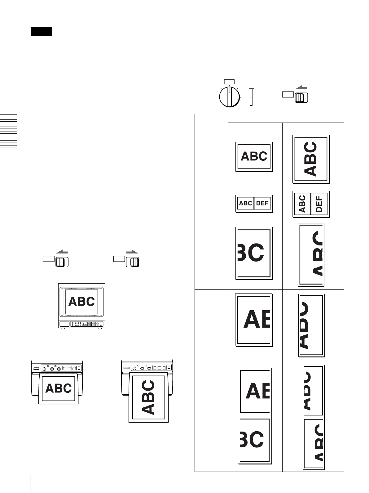
Selecting the Printing Direction/ Image Size
You can make variations of printouts using the STD/
SIDE selector, image size selectors and the DIP
switches.
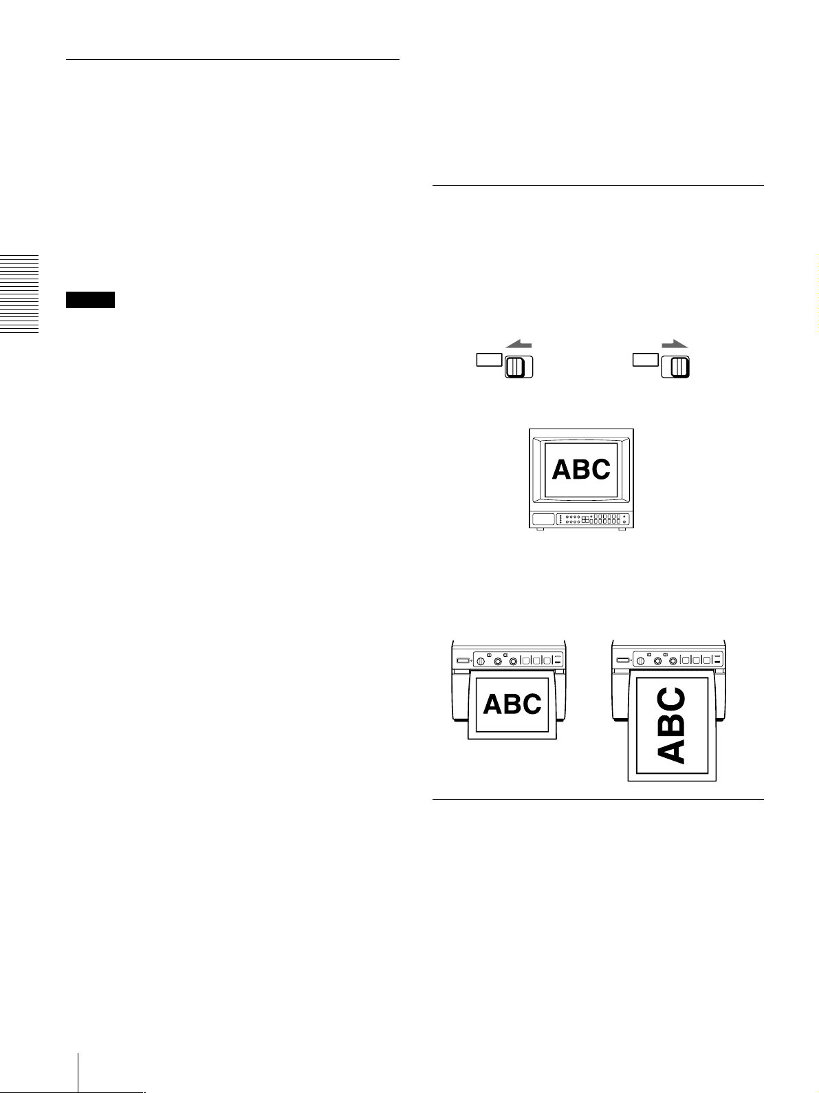
Selecting the printing direction
You can select the printing direction using the STD/
SIDE selector.
To print in the same direction as the one displayed in
the video monitor, set the selector to STD (standard).
To print the image in the direction where the image is
rotated by 90 degrees counterclockwise, set the
selector to SIDE.
STD
Image displayed on the video monitor
SIDE
STD
SIDE
To interrupt copying
Press either the OPEN or FEED button.
Printouts
When set to the STD When set to the SIDE
position position
Selecting the image size
You can print in normal or small size by changing the
image size selector.
You can also obtain a printout of the image at the left or
right, top or bottom of the video image on the monitor
after it has been enlarged twice.
28
Operation
Printing
Variations of printouts
Printouts obtained by the combination of the
STD/SIDE selector and image size selector
The table in the right colum shows various printouts that
can be obtained according to the combination of settings
of the STD/SIDE selector and image size selectors.
NOR
SML 2×
R/T
L/B
BOTH
STD
SIDE
In addition to variations in the right colum, the following
printout variation is available.
Negative printouts
You can make negative printouts by setting the POSI/
NEGA switch on the front panel to the NEGA position.
Image size Printing direction selector position
selector
position STD SIDE
NOR
(Normal)
SML
(Small)
R/T
(Right/Top)
Operation
L/B
(Left/Bottom)
BOTH
Operation
29
Printing
Adjusting the Contrast and Brightness
You can adjust the contrast and brightness of the
printout.
CONTR BRIGHT
Operation
To adjust the brightness
You can adjust the brightness of printouts using the
BRIGHT control.
To make the image brighter, turn the BRIGHT control
clockwise.
To make the image darker, turn the BRIGHT control
counterclockwise.
Note
You cannot adjust the image once it has been captured in
memory. Restore an image after adjustment by pressing
the PRINT button.
Remotely Controlling the Printer
You can remotely control the printer using the RM-91
remote control unit or the foot switch connected to the
REMOTE connector on the rear panel.
Since the button on the remote control unit or foot
switch functions exactly same as the PRINT button,
pressing either of them during printing or copying results
in an image being captured and immediately printed
when DIP Switch 1 (INTERRUPT) on the rear panel is
set to ON (SW-DOWN). (See page 24.)
Note
To adjust the contrast and brightness while confirming
the adjusted image on the video monitor, set DIP Switch
8 (OUTPUT) to EE (SW-UP).
After adjusting the contrast and brightness, be sure to
reset DIP Switch 8 to THRU (SW-DOWN).
Since the video signal is directly input to the video
monitor without being processed by the printer when the
setting is THRU, you can monitor the video signal as it
is input directly from the video equipment.
To adjust the contrast
You can adjust the contrast of image using the CONTR
control.
To make the contrast stronger, turn the CONTR
control clockwise.
To make the contrast weaker, turn the CONTR control
counterclockwise.
30
Operation

Precautions/Maintenance
Precautions
On safety
• Check the operating voltage before operation.
Operate the unit only with a power source specified in
“Specifications”.
• Stop operation immediately if any liquid or solid
object falls into the cabinet. Unplug the unit and have
it checked by qualified personnel.
• Unplug the unit from the wall outlet if you will not be
using it for a long time. Disconnect the power cord by
grasping the plug. Never pull the cord itself.
• Do not disassemble the cabinet. Refer servicing to
qualified personnel only.
• Do not touch the cutting blade of the printer.
• Connect the power plug of the printer to a wall outlet
with a protective earth terminal. The safety earth
should be properly established.
On operation
Do not turn the power off while the printer is printing.
The thermal head may be damaged.
Maintenance
Cleaning the cabinet
Do not use strong solvents to clean the printer. Thinner
or abrasive cleansers will damage the cabinet.
Cleaning the thermal head
If the printout is dirty or white stripes appear on the
printouts, clean the thermal head using the cleaning sheet
supplied .
1 Press the power switch to turn on the printer.
Others
2 Press the OPEN button to open the door.
On the printer carriage
Do not carry or move the printer when the paper roll is
placed in the printer. Doing so may cause a malfunction.
On installation
• Place the printer on a level and stable surface.
If you use the printer with placed on an uneven
surface, malfunction of the printer is likely to occur.
• Do not install the printer near heat sources. Avoid
locations near radiators or air ducts, or places subject
to direct sunlight or excessive dust, humidity,
mechanical shock or vibration.
• Provide adequate air circulation to prevent heat buildup. Do not place the printer on surfaces such as rugs,
blankets, etc., or near materials such as curtains and
draperies.
• If the printer is subjected to wide and sudden changes
in temperature, such as when it is moved from a cold
room to a warm room or when it is left in a room with
a heater that tends to produce large amounts of
moisture, condensation may form inside the printer. In
such cases the printer will probably not work properly,
and may even develop a fault if you persist in using it.
If moisture or condensation forms, turn off the power
and allow the printer to stand for at least one hour.
3 Insert the cleaning sheet, with the black surface
facing down, into the groove in paper tray.
Insert into the
groove.
Cleaning sheet
(supplied)
Continue to next page c
Others
31

Maintenance/Specifications
4 Close the door by pushing it.
5 Press the FEED button and keep it pressed.
When the buzzer sounds and the printer start ejecting
the cleaning sheet, release the FEED button.
Keep pressing the FEED button.
x
Others
When the buzzer sounds and the printer
starts ejecting the cleaning sheet,
release the button.
Cleaning is completed.
6 Press the OPEN button to open the door and
remove the cleaning sheet.
7 Close the door by pushing it.
Notes
• Do not press the PRINT or COPY button while the
cleaning sheet is in the printer.
• Clean the head only when necessary. If you clean the
head too often, it may cause a malfunction.
Specifications
Power requirements and consumption
100 to 120 V AC, 50/60 Hz, 1.5 A
220 to 240 V AC, 50/60 Hz, 0.8 A
Operating temperature
5°C to 35°C (41°F to 95°F)
Operating humidity
20 % to 80 % (no condensation
allowed)
Dimensions Approx. 154 × 105 × 260 mm (w/h/d)
Mass Approx. 3.4 kg (7 lb 8 oz), Main unit
Thermal head Thin-film thermal head (with built-
Gradation 256
Resolution (in WIDE 1 mode)
Print size (in NOR and WIDE 1 mode)
Printing speed (in STD and NOR mode)
Picture memory
Input/output connectors
1
⁄8 × 41⁄4 × 101/4 inches)
(6
only
in drive IC) 1280-dot drive
EIA: 1210 × 490 dots
CCIR: 1210 × 582 dots
STD mode
EIA: 94 × 72 mm
CCIR: 94 × 71 mm
SIDE mode
EIA: 126 × 96 mm
CCIR: 126 × 95 mm
About 3.9 seconds/screen (at factory
settings)
800 K × 8 bits for one frame
VIDEO IN (BNC)
EIA or CCIR Composite video
signals
1.0 Vp-p, 75 ohms/high-impedance
(EIA/CCIR automatically
discriminated)
VIDEO OUT (BNC)
EIA or CCIR Composite video
signals
1.0 Vp-p, 75 ohms, loop-through/EE
switchable
32
Others

REMOTE (stereo minijack)
3
2
1
1 GND
2 PRINT SIGNAL (TTL)
Input of LOW pulse over 100 msec.
initiates print.
3 PRINT BUSY (TTL)
Goes HIGH during printing.
Supplied accessories
Paper roll (UPP-110HG) (1)
BNC y BNC connecting cable (1)
AC power cord (1)
Head cleaning sheet (1)
Media label (1)
The following specifications are applied only to the
UP-895MD/895CE models:
Storage and transport temperature
–20°C to 60°C (–4°F to 140°F)
Storage and transport humidity
20 % to 80 % (no condensation
allowed)
Protection against electric shock
Class I
Protection against harmful ingress of water
Ordinary
Degree of safety in the presence of flammable
anesthetics or oxygen
Not suitable for use in the presence of
flammable anesthetics or oxygen
Mode of operation
Continuous
Specifications
Others
Design and specifications are subject to change
without notice.
Others
33

Troubleshooting
Troubleshooting
The following troubleshooting checks will help you
correct the most common problems you may encounter
with your printer. Before proceeding with these trouble
check, first checks that the power cord is firmly
connected. Should the problem persist, unplug the
printer and contact your Sony dealer or local authorized
Sony service facility.
Symptom
White specks on the
first few printouts.
Printing does not
start when you press
the PRINT button.
Others
Black borders or
missing portions
around the printout.
Paper jam
The printout is dirty.
Cause/remedy
When printing with a newly inserted
roll of paper, dust on the surface of
the paper may cause white specks
on the printouts.
t Feed the paper by pressing the
FEED button until clean paper
appears. (page 26)
• Paper does not feed.
t Is the paper slack?
t Is the power turned on?
t Are all connections correct?
t Did you press the PRINT
button twice in SMALL mode?
(page 27)
• When the alarm buzzer sounds:
t Has the thermal head
overheated? The thermal
head may overheat when the
printer prints dark image
continuously. In such a case,
the EMPTY lamp blinks. Wait
until the head cools down.
t Is the video signal of the
image input?
t Is the paper loaded correctly?
• Paper feeds, but printing does
not start.
t Is the paper loaded with the
thermo-sensitive side up?
(page 26)
This problem may result from the
video signal input to the printer.
t Change the setting of the DIP
switches 6 and 7 (SCAN).
(page 24)
• Open the door by pressing the
OPEN button, then pull the
jammed paper slowly and remove
it.
• There is condensation inside the
unit.
t Moving the unit suddenly from
a cold place to a warm place
often results in condensation
forming. In the event of
condensation forming,
remove the paper, turn off the
power and allow the unit to
stand for about one to two
hours.
The thermal head is dirty.
t Clean the thermal head with the
head cleaning sheet supplied
with the unit. (page 31)
Symptom
The printer stops
printing when it
continuously prints
dark images. (The
alarm buzzer
sounds.)
White lines or small
letters on the screen
are not printed
clearly.
Small squares
appear over the
whole screen.
The printout is too
dark or too light.
The printout seems
stretched or
enlarged.
Cause/remedy
This is likely to occur when the
printer prints continuously 15 or
more dark images. In such a case,
the buzzer sounds. This is because
a protective circuit guards against
heat build-up in the thermal head.
Stop printing for a while.
Is DIP Switch qa (INPUT) set to B &
W when the input signal is a black
and white signal? (page 25)
Is DIP Switch qa (INPUT) set to
COLOR when the input signal is a
color signal? (page 25)
• Is the DIP switch qs (75Ω ) set
correctly? (page 25)
• Is the PAPER TYPE switch in the
paper tray set correctly? (page
23)
• Is the GAMMA switch in the paper
tray set correctly? (page 23)
The DIP switch 3 (ASPECT) is set
to 1:1.
t Set it to 4:3. (page 24)
34
Others

Location and Function of Parts
For details, refer to the pages indicated in parentheses.
Front
1 23456 7 8 9 q; qa qs
STD
POSI
NOR
SML 2×
R/T
L/B
BOTH
SIDE NEGA
CONTR BRIGHT
FEED COPY PRINT
EMPTY
OPEN
Location and Function of Parts
Front
1 Power switch and lamp
Turns the power on. The power lamp is lit while the
power is on.
2 Image size selector (29)
Selects the size of the image to be printed.
3 STD (standard)/SIDE selector (28, 29)
Selects the printing direction.
4 CONTR (contrast) control (30)
Adjusts the contrast of the printouts.
5 POSI(positive)/NEGA (negative) selector (29)
Set this to the NEGA position to make negative
printouts.
6 BRIGHT (brightness) control (30)
Adjusts the brightness of the printouts.
Back
213456
REMOTE
DOWN
DIP SW
UP
t IN T OUT
VIDEO
AC IN
FEED button (26, 27, 28, 32)
7
Press to feed paper. The paper feeds as long as the
FEED button is held down.
Pressing this button during printing results in an
interruption of the printing.
COPY button (28)
8
Prints another copy of the previous printout.
PRINT button (27)
9
Prints the image currently displayed on the video
monitor. The image displayed when you press the
PRINT button is stored in memory.
0 EMPTY lamp (27)
Lights when the printer is out of paper.
Continue to next page c
Others
UP-895MD/895CE
Others
35

Location and Function of Parts
qa OPEN button (26, 31)
Opens or closes the door. Also, interrupts printing
midway.
When the door is open, you can see the slide
switches in the paper tray.
OFF OFF ON
1 SHARPNESS switch
Adjusts the sharpness of the printout.
2 GAMMA switch
Sets the tone of the printouts (density gradation).
3 PAPER TYPE switch
Others
Selects the paper type.
4 SMOOTHING switch
Selects the line density.
For detailed information on slide switches, see
“Setting the Slide Switches on the Paper Tray” on
page 22.
GAMMA
1234
PAPER TYPE
HD HGS
SMOOTHINGSHARPNESS
Back
1 Equipotential terminal (only for UP-895MD/
895CE)
Used to connect to the equipotential plug to bring the
various parts of a system to the same potential.
Refer to “Important safeguards/notice for use in the
medical environments” on page 20.
REMOTE connector (22, 30)
2
Connect the RM-91 remote commander or the foot
switch for controlling print operation from a
distance.
3 DIP SW (switches) (23)
Sets the print modes and functions.
4 tVIDEO IN (input) connector (BNC type) (22)
Connect to the video output connector of the video
equipment.
5 TVIDEO OUT (output) connector (BNC type)
(22)
Connect to the video input connector of the video
monitor. The output signal type depends on DIP
switch 8 (OUTPUT).
6 -AC IN (AC power input) connector (22)
Connect to a wall outlet using the AC power cord
supplied with the unit.
qs Paper feeder and cutter
Cuts the printing paper.
36
Others

Others
Others
37

Français
AVERTISSEMENT
Pour prévenir tout risque d’incendie ou d’électrocution,
garder cet appareil à l’abri de la pluie et de l’humidité.
Pour prévenir tout risque d’électrocution, ne pas ouvrir le
boîtier. Confier l’entretien de cet appareil exclusivement à
un personnel qualifié.
CET APPAREIL DOIT ÉTRE RELIÉ À LA TERRE.
Pour UP-895MD/895CE
Symbole
Ce symbole indique la borne équipotentielle
qui ramène les différentes parties d’un
système à la même tension.
Ce symbole est destiné à attirer l’attention
de l’utilisateur sur la présence d’instructions
d’utilisation et de maintenance (réparation)
importantes dans la documemtation
accompagnant l’appareil.
Pour les utilisateurs au Canada
(pour UP-895MD)
Cet appareil a été homologué conformément à la norme
CSA C22.2 No.601.1.
Avertissement sur le connecteur
d’alimentation pour usage médical
Prière d’utiliser le code d’alimentation électrique suivant.
Avec des connecteurs (fiche ou fiche femelle) et des types
de câbles différents de ceux indiqués dans ce tableau,
utiliser le câble d’alimentation électrique agréé pour votre
secteur.
Etats-Unis Canada
Type de fiche CLASSE HOPITAL* CLASSE HOPITAL*
Fiche femelle E62405, E35708 LR53182, LL022442,
LL088408
Type de câble E159216, E35496 LL112007-1, LL20262,
Min.Type SJT LL32121, LL84494
Min. 18AWG Min. Type SJT
MIN.18AWG
Intensité 10A/125V 10A/125V
nominale du
câble minimale
Agréation de UL Listed CSA
sécurité
Pour UP-895MD/895CE
Instructions de sécurité importantes en vue d’une
utillsation dans un environnement médical
1. Tous les équipements raccordés à cet appareil doivent
être agréés suivant les normes IEC601-1, IEC950,
IEC65 ou les autres normes IEC/ISO applicables à ces
équipements.
2. Si cet appareil est utilisé conjointement avec d’autres
équipements à proximité d’un patient*, ces équipements
doivent être alimentés par un transformateur d’isolement
ou raccordés à la mise à la terre du système par une
borne de terre de protection sauf s’ils sont agréés
suivant la norme IEC601-1.
* Proximité d’un patient
R1.5m
3. Dans le cas d’une connexion à d’autres équipements, le
courant de fuite peut augmenter.
4. Cet appareil génère, utilise et peut émettre des
radiofréquences. S’il n’est pas installé et utilisé
conformément au mode d’emploi, il peut provoquer des
interférences avec d’autres appareils. Si cet appareil
génère des interférences (ce que l’on peut facilement
contrôler en débranchant le cordon d’allmentation de
l’appareil), appliquez l’une des mesures sulvantes :
Installez cet appareil à un autre endroit en tenant
compte de l’autre équipement. Branchez cet appareil et
l’autre équipement sur des circuits d’alimentation
différents. Consultez votre revendeur. (Suivant les
normes EN60601-1-2 et CISPR11, Classe B, Groupe 1)
Attention
Lorsque vous éliminez l’appareil ou ses accessoires, vous
devez vous conformer aux dispositions légales applicables
en la matière dans votre zone géographique ou dans votre
pays ainsi qu’au règlement de l’hôpital en question.
*Remarque: La fiabilité de la mise à la terre n’est réalisable
que si l’équipement est branché sur une prise
de courant équivalente identifiée “Hôpital
uniquement” ou “Classe hôpital”.
38
Introduction

Table des matières/Présentation
Table des matières
Introduction
Présentation............................................................ 39
Préparation
Raccordement ........................................................ 40
Configuration de l’imprimante ............................ 40
Réglage des curseurs du magasin à papier ......... 40
Réglage des microcommutateurs du panneau
arrière.................................................................. 41
Papier ...................................................................... 43
Chargement du papier .......................................... 44
Opération
Impression .............................................................. 45
Réalisation de tirages.......................................... 45
Sélection du sens d’impression/format
d’impression ....................................................... 46
Réglage du contraste et de la luminosité ............ 48
Commande à distance de l’imprimante .............. 48
Autres
Précautions ............................................................. 49
Entretien ................................................................. 49
Spécifications.......................................................... 50
Dépannage .............................................................. 52
Localisation et fonction des composants.............. 53
Avant .................................................................. 53
Arrière ................................................................ 54
Présentation
La UP-895/895MD/895CE est une imprimante
graphique vidéo noir et blanc qui peut être utilisée pour
imprimer des images affichées sur un moniteur vidéo.
Le présent mode d’emploi concerne les modèles UP895/895MD/895CE. Lorsque le fonctionnement ou tout
autre élément diffère entre les divers modèles, ce mode
d’emploi en fournit une description précise.
Qualité d’impression claire et homogène
• Impression haute définition 12,8 points/mm grâce à
l’utilisation d’une tête thermique à CI d’entraînement
ultrarapide.
• 256 gradations de noir et blanc.
• Tirages stables grâce à la technologie de compensation
de température
Impression rapide
• Vous pouvez réaliser un tirage A-7 en environ 3,9
secondes en mode STD et NORM.
• Vous pouvez réaliser un maximum de 11 copies en
continu de la même image.
Deux sens d’impression et différents formats
d’impression
• Le sélecteur de sens d’impression sur le panneau
frontal vous permet d’imprimer dans les sens vertical
et horizontal.
• Le sélecteur de format d’impression situé sur le
panneau frontal vous permet de sélectionner différents
types de formats d’impression.
Optimisation de l’imprimante par des
microcommutateurs et curseurs
• Vous pouvez régler la qualité d’impression et
sélectionner le type de papier en ajustant les curseurs.
• Vous pouvez réaliser des tirages en commençant par le
bas ou par le haut de l’image en réglant le
microcommutateur DIRECTION.
• Vous pouvez régler le format d’impression sur 4 :3 ou
1 :1 à l’aide du microcommutateur ASPECT.
• Vous pouvez régler la zone d’impression à l’aide du
microcommutateur SCAN.
• Vous pouvez économiser du papier à l’aide du
microcommutateur POSTFEED (fonction d’économie
de papier).
Introduction
FR
Français
Identification automatique du signal vidéo
L’imprimante identifie automatiquement le type de
signal d’entrée, noir et blanc (EIA ou CCIR) ou couleur
(NTSC ou PAL), et l’imprime avec la même durée et
dans le même format.
Alarme
L’alarme retentit pour vous signaler une erreur de
manipulation.
Chargement simple et rapide du papier
Vous pouvez charger du papier simplement en ouvrant le
capot et en plaçant un rouleau de papier.
Introduction
39

Raccordement/Configuration de l’imprimante
Raccordement
Remarques
• Mettez tous les appareils hors tension avant de
procéder au raccordement.
• Branchez le câble d’alimentation en dernier lieu.
Préparation
Appareil vidéo
vers le connecteur
de sortie vidéo
Câble de connexion coaxial
fourni (BNC y BNC)
Moniteur vidéo
couleur/noir et
blanc
vers le connecteur
d’entrée vidéo
Câble de connexion
(non fourni)
Configuration de l’imprimante
Vous pouvez configurer l’imprimante suivant les
spécifications de votre choix à l’aide de deux types de
commutateurs.
• Curseurs du magasin à papier à l’intérieur du capot
frontal
Vous pouvez aisément régler l’imprimante suivant les
spécifications les plus fréquemment employées en
utilisation quotidienne, comme la sélection du type de
papier et la qualité d’impression.
• Microcommutateurs du panneau arrière
Vous pouvez sélectionner le mode d’impression et
d’autres réglages que vous ne devez pas changer
fréquemment
Réglage des curseurs du magasin à papier
Les réglages par défaut sont les suivants.
vers VIDEO IN
REMOTE
Télécommande RM-91
(non fournie)
DIP SW
UP
DOWN
vers REMOTE
vers VIDEO OUT
t IN T OUT
VIDEO
AC IN
vers AC IN
Câble d’alimentation
fourni
vers une prise
murale
OFF OFF ON
GAMMA
PAPER TYPE
HD HGS
SMOOTHINGSHARPNESS
1234
A Commutateur SHARPNESS
Réglage de la netteté des tirages.
OFF : Pour ne pas renforcer les contours du tirage,
réglez le commutateur sur cette position.
I, II, III : Pour rendre les contours plus nets, réglez le
commutateur sur la position appropriée. Les positions I,
II et III rendent les tirages progressivement plus nets
40
Préparation

Configuration de l’imprimante
B Commutateur GAMMA
Réglage de la tonalité des tirages (gradation de la densité).
I : Gradation douce
II : Standard
III : Gradation élevée
Le diagramme ci-dessous représente la courbe de la
gradation de la densité pour chaque teinte.
Elevée
I
II
Faible
Remarque
Densité d’impression
0
Gradation
III
255
Ce commutateur est uniquement opérant lorsque vous
employez les types de papier UPP-110HD et UPP110HG, c’est-à-dire lorsque le commutateur PAPER
TYPE 3 est réglé sur II ou V.
Réglage des microcommutateurs du panneau arrière
Pour modifier le réglage des
microcommutateurs
Utilisez un ustensile finement pointu comme un petit
tournevis.
Les réglages par défaut sont les suivants.
123456789q;qaqs
DIP SW
UP
DOWN
121110987654321
Préparation
3 Commutateur PAPER TYPE
Sélection du type de papier.
Réglez ce commutateur suivant le type de papier à
utiliser.
Type de papier Position du commutateur
UPP-110S I (Normal)
UPP-110HD II (Haute densité)
UPP-110HG V (Brillant élevé)
4 Commutateur SMOOTHING
Sélection de la densité des lignes.
OFF : En principe, laissez ce commutateur sur cette
position.
ON : Pour sélectionner une densité d’impression élevée et
obtenir la meilleure qualité d’impression possible, réglez
ce commutateur sur cette position. La vitesse
d’impression est cependant réduite par rapport à la
position OFF.
Remarque
Ce commutateur devient opérant dans les conditions
suivantes :
• Lorsque le sélecteur STD/SIDE du panneau frontal est
réglé sur STD, et que ASPECT du commutateur 3
DIP du panneau arrière est réglé sur 4:3.
• Lorsque le sélecteur du format de l’image du panneau
frontal est réglé sur une position autre que SML ou
NOR et que le sélecteur STD/SIDE est réglé sur SIDE,
et que ASPECT du commutateur 3 DIP est réglé sur
1:1.
Dans toutes les autres circonstances, la densité de la ligne
d’impression n’est pas réglée sur la valeur supérieure
(High) même si vous réglez le commutateur sur ON.
REMOTE
DOWN
DIP SW
UP
t IN T OUT
VIDEO
AC IN
UP-895MD/895CE
DIP SW FUNCTION TABLE
NO. FUNCTION SW-DOWN SW-UP
1 INTERRUPT ON OFF
2 POSTFEED ON OFF
3 ASPECT 4:3 1:1
4 MEMORY FRAME FIELD
5 DIRECTION NORM REV
6 SCAN – WIDE 2
7 WIDE 1 NORM
8 OUTPUT THRU EE
9 AGC OFF ON
10 RESERVED ––
11 INPUT B & W COLOR
12 75 Ω ON OFF
L’indication SW-DOWN ou SW-UP entre
parenthèses donne la position du commutateur.
Préparation
41

275
87654321
475
50
250
9
4
5
5
7
5
4
3
3
2
3
2
30
10
7
0
3
275
87654321
475
50
250
9
4
5
5
7
5
4
3
3
2
3
2
30
10
7
0
3
275
87654321
475
50
250
9
4
5
5
7
5
4
3
3
2
3
2
30
10
7
0
3
275
87654321
475
50
250
9
4
5
5
7
5
4
3
3
2
3
2
30
10
7
0
3
1
5
275
87654321
475
50
250
9
4
5
5
7
5
4
3
3
2
3
2
30
10
7
0
3
275
87654321
475
50
250
9
4
5
5
7
5
4
3
3
2
3
2
30
10
7
0
3
275
87654321
475
50
250
9
4
5
5
7
5
4
3
3
2
3
2
30
10
7
0
3
Configuration de l’imprimante
1 Commutateur INTERRUPT
Définit l’activation de la touche PRINT pour permettre
l’interruption du processus d’impression et saisir une
image dans la mémoire.
ON (SW-DOWN) : Interrompt l’impression en cours et
imprime une nouvelle image lorsque vous appuyez sur la
touche PRINT en cours d’impression.
OFF (SW-UP) : Pour ne pas tenir compte de la
manipulation de la touche PRINT durant l’impression et
poursuit l’impression en cours.
Si vous appuyez sur la touche PRINT en cours
Préparation
d’impression en mode OFF, l’alarme retentit.
2 Commutateur POSTFEED
Définit l’alimentation de papier vierge supplémentaire
lorsqu’une image a été imprimée.
ON (SW-DOWN) : Alimente du papier vierge
supplémentaire lorsqu’une image a été imprimée.
OFF (SW-UP) : N’alimente pas de papier vierge
supplémentaire lorsqu’une image a été imprimée.
Pour économiser du papier en n’alimentant qu’une faible
longueur de papier après avoir imprimé une image,
réglez ce commutateur sur OFF. De cette façon, vous
pouvez réaliser davantage de tirages par rouleau de
papier, mais vous devez alimenter le papier
manuellement à l’aide de la touche FEED et déchirer le
papier. Si vous devez effectuer plusieurs tirages de la
même image, cette position vous permet d’économiser
du papier.
3 Commutateur ASPECT 4 :3/1 :1
En principe, laissez ce commutateur sur 4 :3 (SWDOWN). Si le format du signal vidéo est de 1 :1, réglez-
le sur 1 :1 (SW-UP).
Le tirage sera plus long que s’il avait été réalisé en
format 4 :3.
1
2
3
3
5
2
3
30
4
3
3
4
1 357 7 531
4
3
3
4
30
3
2
5
3
3
2
1
5
2
3
1
3
3
30
4
3
3
4
4
3
3
4
30
3
5
3
3
2
1
4:3
2
2
1
2
3
3
5
2
3
30
4
3
3
4
1 357 7 531
4
3
3
4
30
3
2
5
3
3
2
1
1:1
4 Commutateur MEMORY
FRAME (SW-DOWN) : En principe, laissez ce
commutateur sur cette position.
FIELD (SW-UP) : Lorsque vous imprimez des images
animées d’un mouvement rapide (comme une balle au
bond), il se peut que le tirage soit flou. Si cela se produit,
réglez le commutateur sur cette position. La définition
du tirage est moindre, mais le flou est atténué.
Préparation
42
5 Commutateur DIRECTION
Définit si c’est le haut ou le bas de l’écran qui est
imprimé en premier lieu.
NORM (SW-DOWN) : En principe, laissez ce
commutateur sur cette position. L’impression est
effectuée à partir du bas de l’écran.
REV (SW-UP) : L’impression commence par le haut de
l’écran.
1
2
3
3
5
2
3
30
4
3
3
4
1 357 7 531
4
3
3
4
30
3
2
5
3
3
2
1
NORM REV
5
2
3
1
3
2
3
30
4
3
3
4
4
3
3
4
30
3
2
5
3
3
2
1
1
2
3
3
5
2
3
30
4
3
3
4
4
3
3
4
30
3
2
3
1
3
2
5
1
2
3
3
5
2
3
30
4
3
3
4
1 357 7 531
4
3
3
4
30
3
2
5
3
3
2
1
67 Commutateur SCAN
Définit la zone d’impression. La zone d’impression est
progressivement agrandie dans l’ordre du réglage :
NORM, WIDE 1 et WIDE 2.
NORM (commutateur 7, position SW-UP) : Imprime
uniquement l’image affichée sur le format d’écran
standard du moniteur vidéo.
WIDE 1 (commutateur 7, position SW-DOWN) :
Imprime le signal de balayage en dehors du format
standard du moniteur.
WIDE 2 (commutateur 6, position SW-UP) :
Sélectionnez ce réglage pour agrandir davantage la zone
d’impression.
Pour modifier la gamme des impressions, réglez les
commutateurs DIP selon le tableau suivant.
Dimension Commutateur Commutateur
du scan DIP 6 DIP 7
NORM SW-DOWN SW-UP
5
2
3
1
3
2
3
30
4
3
3
4
WIDE 1 SW-DOWN SW-DOWN
WIDE 2 SW-UP SW-DOWN
Remarque
Ne réglez pas en même temps le commutateur DIP 6 et
le commutateur DIP 7 sur SW-UP.
4
3
3
4
30
3
2
5
3
3
2
1
2
3
3
5
2
3
30
4
3
3
4
357 7 53
4
3
3
4
30
3
2
5
3
3
2
1
2
3
1
3
3
30
4
3
3
4
4
3
3
4
30
3
5
3
3
2
1
NORM
1
2
3
3
5
2
3
30
4
3
3
4
1 357 7 531
4
3
3
4
30
3
2
5
3
3
2
1
5
2
3
1
3
3
30
4
3
3
4
4
3
3
4
30
3
5
3
3
2
1
WIDE 1
2
2
1
2
3
3
5
2
2
2
3
30
4
3
3
4
1 357 7 531
4
3
3
4
30
3
2
5
3
3
2
1
WIDE 2
5
2
3
1
3
2
3
30
4
3
3
4
4
3
3
4
30
3
2
5
3
3
2
1

Configuration de l’imprimante/Papier
8 Commutateur OUTPUT
Sélectionne le signal vidéo sorti via le connecteur
VIDEO OUT du panneau arrière.
THRU (SW-DOWN) : Les signaux sont directement
sortis vers le moniteur vidéo.
EE (SW-UP) : Les signaux sont sortis vers le moniteur
vidéo après avoir été traités par l’imprimante.
Dans ce mode, l’impedance au connecteur VIDEO IN
est de 75 ohms, quel que soit le réglage du commutateur
75Ω ON/OFF qs.
9 Commutateur AGC (réglage automatique du
gain)
Règle le signal d’entrée sur le niveau d’impression
optimal.
OFF (SW-DOWN) : En principe, laissez ce
commutateur sur cette position.
ON (SW-UP) : Si l’image imprimée apparaît trop foncée
ou trop claire, réglez le commutateur sur cette position
pour ajuster le signal d’entrée sur le niveau optimal.
0 Commutateur RESERVED
Laissez ce commutateur sur le réglage par défaut (SWDOWN)
qa Commutateur INPUT
B & W (SW-DOWN) : Si le signal à imprimer est noir
et blanc, réglez le commutateur sur cette position.
COLOR (SW-UP) : Si le signal est en couleur, réglez le
commutateur sur cette position.
qs Commutateur 75Ω ON/OFF
ON (SW-DOWN) : Si rien n’est raccordé au connecteur
VIDEO OUT, réglez le commutateur sur cette position.
OFF (SW-UP) : Si un moniteur vidéo ou un autre
appareil vidéo est raccordé au connecteur VIDEO OUT,
réglez le commutateur sur cette position.
Si le commutateur OUTPUT 8 est réglé sur EE (SWUP), l’impédance au connecteur VIDEO IN est de 75
ohms fixes.
Exemple :
Si vous raccordez deux imprimantes à un appareil vidéo,
réglez le commutateur 75Ω de l’une des imprimantes sur
ON et l’autre sur OFF.
Si vous raccordez l’imprimante et un moniteur vidéo à
l’appareil vidéo, réglez le commutateur 75Ω sur OFF.
Papier
Utilisez uniquement du papier UPP-110S/110HD/
110HG tel que spécifié pour les imprimantes UP-895/
895MD/895CE. Si vous utilisez un autre type de
papier, la qualité des tirages ne peut être garantie.
L’utilisation d’un autre type de papier peut
également provoquer un dysfonctionnement de
l’imprimante.
Vous ne pouvez pas utiliser le papier UPP-110HA
spécifié pour les imprimantes UP-880/890MD/
890CE.
Type de papier
Les types de papier suivants sont disponibles.
Qualité d’impression Type de papier
TYPE I (Normal) UPP-110S
TYPE II (Haute densité) UPP-110HD
TYPE V (Brillant élevé) UPP-110HG
Remarques sur le papier
Rangement du papier non utilisé
Ne rangez pas le papier à des endroits soumis aux
conditions suivantes. Le rangement du papier non utilisé
dans de tels endroits peut entraîner une détérioration du
papier non utilisé.
• Rangez le papier non utilisé à un endroit frais et
sombre (moins de 30 °C ou 86 °F).
• Ne rangez pas le papier inutilisé à un endroit chaud ou
humide. Ne laissez pas du papier non utilisé sous le
rayonnement direct du soleil ou à des endroits fort
éclairés.
• Veillez à ce qu’aucun solvant organique volatile ni de
chlorure de vinyle n’entre en contact avec le papier
non utilisé. L’alcool, les rubans adhésifs ou les films
en plastique provoquent une détérioration du papier
non utilisé.
Chargement du papier
• Ne pliez pas le papier et ne touchez pas la surface
d’impression. La présence de poussière ou de traces de
doigts sur la surface d’impression entraîne une
altération de la qualité d’impression.
• Avant de charger un rouleau de papier, enlevez
l’étiquette fixée sur le rouleau de papier et tirez les
premiers 15 à 20 cm (6 à 8 pouces). La trace laissée
par l’étiquette est la cause d’une mauvaise qualité
d’impression.
Rangement des tirages
• Ne rangez pas les tirages à des endroits soumis aux
conditions suivantes. Rangez vos tirages à un endroit
où ils ne risquent pas de se décolorer.
– Rangez les tirages dans un endroit sombre et frais
(moins de 30 °C ou 86 °F). Nous recommandons de
ranger le papier imprimé dans un sac en papier
exempt d’argile ou en polypropylène.
– Ne rangez pas les tirages à un endroit chaud ou
humide. Ne laissez pas des tirages sous le
rayonnement direct du soleil ou à des endroits fort
éclairés.
– Veillez à ce qu’aucun solvant organique volatile ni
de chlorure de vinyle n’entre en contact avec les
tirages. L’alcool, les rubans adhésifs ou les films en
plastique provoquent une décoloration des tirages.
Préparation
Préparation
43

Papier/Chargement du papier
• N’empilez pas les tirages sur ou sous une diazocopie.
Ne placez pas la surface imprimée contre la surface
imprimée d’un autre tirage. Les tirages risquent en
effet de se décolorer.
• Pour fixer un tirage sur une autre surface en papier,
utilisez de l’adhésif double face ou encore de la colle à
base aqueuse.
Chargement du papier
Préparation
Remarques
• Avant de charger du papier, lisez la section “Papier” à
la page 43.
• Ne pliez pas le papier et ne touchez pas la surface
d’impression. La présence de poussière ou de traces de
doigts entraîne une altération de la qualité
d’impression.
• Utilisez uniquement du papier UPP-110S/110HD/
110HG tel que spécifié pour cette imprimante. (page
43)
• Réglez le commutateur PAPER TYPE suivant le type
de papier. (page 41)
Remarque
Lorsque vous tirez sur le dessus du rouleau de papier
ou que vous le placez dans le magasin à papier,
veillez à ne pas laisser tomber le rouleau de papier.
Si de la poussière s’est accumulée sur le papier, il se
peut que vous ne puissiez plus l’utiliser parce que la
présence de poussière ou de traces de doigts est
susceptible d’entraîner une altération de la qualité
d’impression ou un dysfonctionnement de la tête.
Enlevez l’étiquette et tirez les
premiers 15 à 20 cm (6 à 8
pouces) de papier.
Placez le papier avec la face thermosensible
(face d’impression) vers le haut. Si vous placez
par erreur le papier avec la face d’impression
vers le bas, l’image ne sera pas imprimée.
Chargement
1 Appuyez sur le contacteur d’alimentation pour
mettre l’imprimante sous tension.
Le témoin de mise sous tension s’allume.
2 Appuyez sur le bouton OPEN pour ouvrir le
capot.
Placez le rouleau de
papier de façon à ce
que le papier sorte
tendu du magasin à
papier.
4 Refermez le capot en appuyant dessus.
3 Enlevez l’étiquette fixée sur le rouleau de papier
et tirez les premiers 15 à 20 cm (6 à 8 pouces),
puis placez le rouleau de papier dans le magasin à
papier.
44
Préparation
Remarques
• Si le rouleau de papier n’est pas correctement placé et
ne sort pas tendu du magasin à papier, un bourrage de
papier risque de se produire.
• Si vous ne tirez pas suffisamment sur le papier à
l’étape 3, faites avancer le papier d’au moins 15 à 20
cm en maintenant la touche FEED enfoncée. Ne tirez
pas sur le papier manuellement.

Impression
Impression
Pour interrompre une impression en cours
Appuyez sur la touche OPEN ou FEED pendant
l’impression. L’imprimante arrête l’impression en cours.
Avant de réaliser des tirages
Vérifiez les éléments suivants :
• Les connexions ont-elles été correctement réalisées ?
(page 40)
• Les curseurs et les microcommutateurs sont-ils réglés
correctement ? (pages 40 et 41)
• Le type de papier est-il réglé correctement ? (page 41)
• Le rouleau de papier est-il correctement chargé ? (page
44)
• La source vidéo est-elle raccordée ?
Réalisation de tirages
1 Appuyez sur le contacteur d’alimentation pour
mettre l’imprimante sous tension.
Le témoin de mise sous tension s’allume et le témoin
EMPTY clignote pendant quelques secondes.
Témoin d’alimentation
Témoin EMPTY
Remarque
Assurez-vous que le témoin EMPTY s’éteint après
avoir clignoté pendant quelques secondes. S’il reste
allumé, c’est que le papier est épuisé. Chargez du
papier. (“Chargement du papier” à la page 44)
2 Sélectionnez le sens et le format d’impression.
Voir “Sélection du sens d’impression/format
d’impression” à la page suivante.
Pour arrêter l’impression et imprimer une
autre image affichée sur le moniteur vidéo
Pour cette opération, le microcommutateur 1
(INTERRUPT) doit être réglé sur ON (SW-DOWN).
(Voir page 42)
Appuyez sur la touche PRINT pendant l’impression ou
la copie. L’imprimante arrête l’impression, saisit la
nouvelle image et démarre l’impression de la nouvelle
image.
En mode SMALL, l’imprimante arrête l’impression et
saisit la première image.
Si l’image imprimée est floue
Une image animée d’un mouvement rapide peut
apparaître floue à l’impression. Si cela se produit,
changez le microcommutateur 4 (MEMORY) sur la
position FIELD (SW-UP). (Voir page 42) La qualité
d’impression sera moins bonne, mais le flou s’en
trouvera atténué.
Pour imprimer en mode SMALL
Vous pouvez imprimer en mode SMALL, lorsque deux
images différentes peuvent être saisies et imprimées
simultanément sur le même tirage, en réglant le sélecteur
du format de l’image du panneau frontal sur la position
SML.
Pour imprimer en mode SMALL : Appuyez deux fois
sur la touche PRINT à l’étape 4. Si vous n’appuyez
qu’une fois sur la touche PRINT, le vibreur retentit et la
première image est saisie. L’imprimante démarre
l’impression après que vous avez appuyé deux fois sur la
touche PRINT.
Pour des informations plus détaillées sur le mode
SMALL, voir “ Sélection du sens d’impression/format
d’impression” à la page suivante.
Opération
3 Démarrez la source vidéo.
Cette opération se fait à l’aide des commandes de
l’appareil vidéo que vous utilisez comme source
vidéo.
4 Lorsque l’image que vous voulez imprimer est
affichée sur le moniteur vidéo, appuyez sur la
touche PRINT.
L’image affichée au moment où vous appuyez sur la
touche PRINT est saisie dans la mémoire et est
immédiatement imprimée.
Pour alimenter le papier
Maintenez la touche FEED enfoncée pour alimenter le
papier.
Ne tirez pas sur le papier manuellement.
Rangement des tirages
• Ne rangez pas les tirages à des endroits soumis aux
conditions suivantes. Rangez vos tirages à un endroit
où ils ne risquent pas de se décolorer.
– Rangez les tirages dans un endroit sombre et frais
(moins de 30 °C ou 86 °F). Nous recommandons de
ranger le papier imprimé dans un sac en papier
exempt d’argile ou en polypropylène.
– Ne rangez pas les tirages à un endroit chaud ou
humide. Ne laissez pas des tirages sous le
rayonnement direct du soleil ou à des endroits fort
éclairés.
Opération
45

Impression
– Veillez à ce qu’aucun solvant organique volatile ni
de chlorure de vinyle n’entre en contact avec les
tirages. L’alcool, les rubans adhésifs ou les films en
plastique provoquent une décoloration des tirages.
• N’empilez pas les tirages sur ou sous une diazocopie.
Ne placez pas la surface imprimée contre la surface
imprimée d’un autre tirage. Les tirages risquent en effet
de se décolorer.
• Pour fixer un tirage sur une autre surface en papier,
utilisez de l’adhésif double face ou encore de la colle à
base aqueuse.
Pour réaliser une copie du dernier tirage
Appuyez sur la touche COPY. L’imprimante réalise une
copie du dernier tirage. Le dernier tirage est conservé
dans la mémoire de l’imprimante jusqu’à ce que vous
appuyiez de nouveau sur la touche PRINT ou que vous
Opération
mettiez le système hors tension.
Pour copier dans un sens et un format
différents
Vous pouvez copier le dernier tirage dans différents sens
et formats, sauf en mode SMALL.
Avant d’appuyer sur la touche COPY, sélectionnez le
sens et le format d’impression comme décrit dans
“Sélection du sens d’impression/format d’impression”
(Voir sur cette page).
Sélection du sens d’impression/ format d’impression
Vous pouvez réaliser plusieurs variantes d’un tirage à
l’aide du sélecteur STD/SIDE, du sélecteur du format de
l’image et des microcommutateurs.
Sélection du sens d’impression
Vous pouvez sélectionner le sens d’impression à l’aide
du sélecteur STD/SIDE.
Pour imprimer dans le même sens que celui affiché
sur le moniteur vidéo, réglez le sélecteur sur STD
(standard).
Pour imprimer l’image après l’avoir fait pivoter de
90 degrés dans le sens antihoraire, réglez le sélecteur
sur SIDE.
STD
Image affichée sur le moniteur vidéo
SIDE
STD
SIDE
Remarques
• Si vous appuyez sur la touche COPY immédiatement
après avoir mis l’imprimante sous tension, l’alarme
retentit étant donné qu’aucune image n’est enregistrée
dans la mémoire.
• Si, lorsque vous êtes en mode SMALL, vous appuyez
sur la touche COPY alors que vous n’avez appuyé
qu’une seule fois sur la touche PRINT, l’alarme retentit
et l’imprimante n’exécute pas la copie.
Pour réaliser plusieurs copies du même tirage
Appuyez sur la touche COPY autant de fois que
nécessaire (11 copies au maximum, le tirage initial
compris) pendant l’impression ou la copie initiale. Un
bref signal sonore retentit chaque fois que vous appuyez
sur la touche COPY.
Pour interrompre le cycle de copie
Appuyez sur la touche OPEN ou FEED.
Tirages
Réglé sur la Réglé sur la
position STD position SIDE
Sélection du format d’image
Vous pouvez imprimer en petit ou en grand format en
changeant le sélecteur du format de l’image.
Vous pouvez également obtenir un tirage de la partie
gauche, droite, supérieure ou inférieure de l’image vidéo
agrandie deux fois.
46
Opération

Impression
Variantes d’un même tirage
Les tirages obtenus par la combinaison du
sélecteur STD/SIDE et du sélecteur de format
d’image
Le tableau de la colonne de droit présente les différents
tirages qu’il est possible d’obtenir en fonction de la
combinaison des réglages du sélecteur STD/SIDE et du
sélecteur de format d’image.
NOR
SML 2×
R/T
L/B
BOTH
STD
SIDE
En plus des diverses variantes de la colonne de droit, la
variante de tirage que voici est également possible.
Tirages négatifs
Vous pouvez réaliser des tirages négatifs en réglant le
commutateur POSI/NEGA du panneau frontal sur la
position NEGA.
Réglage du Réglage du sélecteur de sens
sélecteur du
format de
l’image STD SIDE
NOR
(Normal)
SML
(petit)
R/T
(droit/haut)
d’impression
Opération
L/B
(gauche/bas)
BOTH
Opération
47

Impression
Réglage du contraste et de la luminosité
Vous pouvez régler le contraste et la luminosité des
tirages.
CONTR BRIGHT
Opération
Remarque
Pour régler le contraste et la luminosité tout en vérifiant
l’image ainsi corrigée sur le moniteur vidéo, réglez le
microcommutateur 8 (OUTPUT) sur EE (SW-UP).
Après avoir réglé le contraste et la luminosité, n’oubliez
pas de ramener le microcommutateur 8 sur THRU
(SW-DOWN).
Etant donné que le signal vidéo est directement entré sur
le moniteur vidéo sans être traité par l’imprimante
lorsque le réglage est THRU, vous pouvez contrôler le
signal vidéo puisqu’il est directement entré depuis
l’appareil vidéo.
Pour régler la luminosité
Vous pouvez régler la luminosité des tirages à l’aide de
la commande BRIGHT.
Pour rendre l’image plus claire, tournez la commande
BRIGHT dans le sens horaire.
Pour rendre l’image plus foncée, tournez la commande
BRIGHT dans le sens antihoraire.
Remarque
Vous ne pouvez pas régler l’image après qu’elle a été
saisie dans la mémoire. Appuyez sur la touche PRINT
pour restaurer une image après l’avoir réglée.
Commande à distance de l’imprimante
Vous pouvez commander l’imprimante à distance à
l’aide d’une télécommande RM-91 ou d’une commande
au pied raccordée au connecteur REMOTE du panneau
arrière.
Etant donné que le bouton de la télécommande et de la
commande au pied fonctionne exactement de la même
manière que la touche PRINT, appuyez sur l’un ou
l’autre pendant l’impression ou la copie pour saisir une
image et l’imprimer immédiatement lorsque le
microcommutateur 1 (INTERRUPT) du panneau
arrière est réglé sur ON (SW-DOWN). (Voir page 42)
Pour régler le contraste
Vous pouvez régler le contraste de l’image à l’aide de la
commande CONTR.
Pour augmenter le contraste, tournez la commande
CONTR dans le sens horaire.
Pour diminuer le contraste, tournez la commande
CONTR dans le sens antihoraire.
48
Opération

Précautions/Entretien
Précautions
Sécurité
• Vérifiez la tension secteur avant toute utilisation.
Faites uniquement fonctionner l’appareil avec l’une des
sources d’alimentation spécifiées dans les
“Spécifications”.
• Interrompez immédiatement le fonctionnement de
l’imprimante si un liquide ou un solide tombe à
l’intérieur du châssis. Débranchez l’appareil et faites-le
vérifier par le personnel qualifié.
• Débranchez l’appareil de la prise murale si vous
prévoyez de ne pas l’utiliser pendant une période
prolongée. Débranchez le câble d’alimentation en le
saisissant par la fiche. Ne tirez jamais sur le câble
proprement dit.
• Ne démontez pas le châssis. Confiez-en exclusivement
l’entretien au personnel qualifié.
• Ne touchez pas la lame du coupe-papier de
l’imprimante.
• Branchez la fiche du câble d’alimentation sur une prise
murale mise à la terre. L’imprimante doit être
correctement reliée à la terre.
Entretien
Nettoyage du châssis
N’utilisez pas de solvants puissants pour nettoyer le
châssis de l’imprimante. Le diluant et les nettoyants
abrasifs risquent d’altérer le fini du châssis.
Nettoyage de la tête thermique
Si les tirages présentent des souillures ou si des bandes
blanches apparaissent sur les tirages, nettoyez la tête
thermique à l’aide de la feuille de nettoyage fournie.
1 Appuyez sur l’interrupteur d’alimentation pour
mettre l’imprimante sous tension.
Autres
Utilisation
Ne mettez pas l’imprimante hors tension pendant un
cycle d’impression. Vous risqueriez d’endommager la
tête thermique.
Transport de l’imprimante
Ne transportez et ne déplacez pas l’imprimante quand le
rouleau de papier est installé à l’intérieur. Cela risquerait
de provoquer un dysfonctionnement.
Installation
• Installez l’imprimante sur une surface plane et stable.
Si vous utilisez l’imprimante placez sur une surface
inégale, l’imprimante risque de présenter une
défaillance.
• N’installez pas l’imprimante à proximité d’une source
de chaleur comme un radiateur, une conduite d’air
chaud et ne la soumettez pas au rayonnement direct du
soleil, à de la poussière ou à une humidité excessive, à
des chocs mécaniques ou à des vibrations.
• Veillez à assurer une circulation de l’air adéquate pour
éviter toute surchauffe. Ne placez pas l’imprimante sur
des surfaces telles que des tapis, etc., ou à proximité de
rideaux et de draperies.
• Si l’imprimante est soumise à des variations brusques
et importantes de température, par exemple lorsqu’elle
est transportée d’un local froid dans un local chaud ou
lorsqu’elle reste dans un local avec un chauffage ayant
tendance à produire une forte humidité, de la
condensation risque de se former à l’intérieur de
l’imprimante. En pareil cas, l’imprimante ne
fonctionnera probablement pas correctement et risque
de présenter une défaillance si vous persistez à vouloir
l’utiliser. Si de l’humidité ou de la condensation se
forme, mettez l’imprimante hors tension et laissez-la
reposer pendant au moins une heure.
2 Appuyez sur OPEN pour ouvrir le capot.
3 Introduisez la feuille de nettoyage avec la face
noire vers le bas dans la rainure du magasin à
papier.
Introduisez
dans la
rainure.
Feuille de
nettoyage
(fournie)
à suivre c
Autres
49

Entretien/Spécifications
4 Refermez le capot en poussant dessus.
5 Maintenez la touche FEED enfoncée.
Lorsque le vibreur retentit et que l’imprimante
commence à éjecter la feuille de nettoyage, relâchez
la touche FEED.
Maintenez la touche FEED enfoncée.
x
Autres
Lorsque le vibreur retentit et que
l’imprimante commence à éjecter la
feuille de nettoyage, relâchez la touche.
Le nettoyage est terminé.
6 Appuyez sur la touche OPEN pour ouvrir le
capot et retirer la feuille de nettoyage.
7 Refermez le capot en poussant dessus.
Remarques
• N’appuyez pas sur la touche PRINT ou COPY pendant
que la feuille de nettoyage se trouve à l’intérieur de
l’imprimante.
• Ne nettoyez la tête thermique que lorsque cela s’avère
nécessaire. Un nettoyage trop fréquent risque de
provoquer un dysfonctionnement.
Spécifications
Puissance de raccordement et consommation
100 à 120 V CA, 50/60 Hz, 1,5 A
220 à 240 V CA, 50/60 Hz, 0,8 A
Température de service
5 à 35 °C (41 à 95 °F)
Humidité de service
20 à 80 % (sans condensation)
Dimensions Approx. 154 × 105 × 260 mm (l/h/p)
Masse Approx. 3,4 kg (7 lb 8 oz), appareil
Tête thermique
Gradation 256
Résolution (en mode WIDE 1)
Format d’impression (en modes NOR et WIDE 1)
Vitesse d’impression (en modes STD et NOR)
Mémoire d’image
Connecteurs d’entrée/sortie
1
/8 × 41/4 × 101/4 pouces)
(6
principal uniquement
Tête thermique à couche mince (avec
CI d’entraînement intégré)
Entraînement de 1280 points
EIA : 1210 × 490 points
CCIR : 1210 × 582 points
Mode STD
EIA : 94 × 72 mm
CCIR : 94 × 71 mm
Mode SIDE
EIA : 126 × 96 mm
CCIR : 126 × 95 mm
Environ 3,9 secondes/écran
(réglages par défaut)
800 K × 8 bits par image
VIDEO IN (BNC)
Signaux vidéo composites EIA ou
CCIR
1,0 Vp-p, 75 ohms/haute impédance
(EIA/CCIR discriminés
automatiquement)
VIDEO OUT (BNC)
Signaux vidéo composites EIA ou
CCIR
1,0 Vp-p, 75 ohms, sortie boucle
directe/EE commutable
50
Autres

REMOTE (miniprise stéréo)
3
2
1
1 GND
2 PRINT SIGNAL (TTL)
Entrée d’une impulsion LOW sur
100 ms pour initialiser l’impression.
3 PRINT BUSY (TTL)
Devient HIGH pendant l’impression.
Accessoires fournis
Rouleau de papier (UPP-110HG) (1)
Câble de connexion BNC y BNC (1)
Câble d’alimentation (1)
Feuille de nettoyage de la tête
thermique (1)
Etiquette de support (1)
Les spécifications concernent uniquement les
modèles UP-895MD/895CE :
Température de stockage et de transport
–20 à 60 °C (–4 à 140 °F)
Humidité de stockage et de transport
20 à 80 % (sans condensation)
Protection contre les chocs électriques
Classe I
Protection contre la pénétration néfaste d’eau
Ordinaire
Degré de sécurité en présence d’anesthésiants
inflammables ou d’oxygène
Ne convient pas à une utilisation en
présence d’anesthésiants
inflammables ou d’oxygène
Mode de fonctionnement
Continu
Spécifications
Autres
La conception et les spécifications sont sujettes à
modifications sans préavis.
Autres
51

Dépannage
Dépannage
Le guide de dépannage que voici vous aidera à remédier
à la plupart des problèmes que vous pourriez rencontrer
avec votre imprimante. Avant de procéder à ces
vérifications, commencez par contrôler si le câble
d’alimentation est correctement branché. Si le problème
persiste, débranchez l’imprimante et consultez votre
revendeur Sony ou un centre de service après-vente Sony
agréé.
Symptômes
De petites taches
blanches
apparaissent sur les
premiers tirages.
L’impression ne
Autres
démarre pas lorsque
vous appuyez sur la
touche PRINT.
Il y a des bordures
noires ou des
portions manquantes
autour du tirage.
Cause/remèdes
Lors de l’impression avec un
nouveau rouleau de papier, de la
poussière à la surface du papier
risque de donner de petites taches
blanches sur le tirage.
t Avancez le papier en appuyant
sur la touche FEED jusqu’à ce
que du papier propre
apparaisse. (page 44)
• Le papier n’avance pas.
t Le papier est-il détendu ?
t L’imprimante est-elle sous
tension ?
t Toutes les connexions sont-
elles correctes ?
t Avez-vous appuyé deux fois
sur la touche PRINT en mode
SMALL ? (page 45)
• Si l’alarme retentit :
t La tête thermique surchauffe-
t-elle ? La tête thermique
peut surchauffer lorsque
l’imprimante imprime des
images foncées en continu.
En pareil cas, le témoin
EMPTY se met à clignoter.
Attendez que la tête se
refroidisse.
t Le signal vidéo de l’image est-
il entré ?
t Le papier est-il chargé
correctement ?
• Le papier est avancé, mais
l’impression ne démarre pas.
t Le papier est-il chargé avec la
face thermosensible vers le
haut ? (page 44)
Ce problème peut être dû au signal
vidéo entrant dans l’imprimante.
t Changez le réglage des
commutateurs 6 et 7
(SCAN). (page 42)
Symptômes
Bourrage de papier
Les tirages sont
souillés.
L’imprimante s’arrête
lorsqu’elle imprime
des images noires
en continu. (Le
vibreur retentit.)
Des lignes blanches
ou de petites lettres
apparaissant à
l’écran ne sont pas
imprimées avec
netteté.
De petits carrés
apparaissent sur
toute la surface de
l’écran.
Le tirage est trop
foncé ou trop clair.
Le tirage semble
étiré ou agrandi.
Cause/remèdes
• Ouvrez la réserve à papier en
appuyant sur la touche OPEN,
retirez lentement le papier coincé
et refermez-le.
• De la condensation s’est formée à
l’intérieur de l’imprimante.
t Lorsque l’imprimante est
amenée brusquement d’un
endroit froid dans un endroit
chaud, il arrive fréquemment
que de la condensation se
forme à l’intérieur. Dans ce
cas, retirez le papier, mettez
l’imprimante hors tension et
laissez-la au repos pendant
une heure ou deux.
La tête thermique est encrassée.
t Nettoyez la tête thermique à
l’aide de la feuille de nettoyage
fournie. (page 49)
Ce problème se produit lorsque
l’imprimante imprime en continu
plus de 15 images foncées. Dans ce
cas, l’alarme retentit. La cause en
est que le circuit de protection se
déclenche pour éviter une
surchauffe de la tête thermique.
Stoppez l’imprimante pendant un
moment.
Le microcommutateur qa (INPUT)
est-il réglé sur B & W lorsque le
signal d’entrée est un signal noir et
blanc ? (page 43)
Le microcommutateur qa (INPUT)
est-il réglé sur COLOR lorsque le
signal d’entrée est un signal
couleur ? (page 43)
• Le microcommutateur qs (75Ω )
est-il réglé correctement ? (page
43)
• Le commutateur PAPER TYPE du
magasin à papier est-il réglé
correctement ? (page 41)
• Le commutateur GAMMA du
magasin à papier est-il réglé
correctement ? (page 41)
Le microcommutateur 3 (ASPECT)
est réglé sur 1 :1.
t Réglez-le sur 4 :3. (page 42)
52
Autres

Localisation et fonction des composants
Pour plus de détails, reportez-vous aux pages indiquées
entre parenthèses.
Localisation et fonction des composants
Avant
1 Interrupteur et témoin d’alimentation
Met l’imprimante sous tension. Le témoin est allumé
lorsque l’imprimante est sous tension.
2 Sélecteur du format de l’image (47)
Sélectionne le format de l’image à imprimer.
3 Sélecteur STD (standard)/SIDE (46, 47)
Sélectionne le sens d’impression.
Avant
1 23456 7 8 9 q; qa qs
STD
POSI
NOR
SML 2×
R/T
L/B
BOTH
SIDE NEGA
CONTR BRIGHT
FEED COPY PRINT
EMPTY
OPEN
Arrière
4 Commande CONTR (contraste) (48)
Règle le contraste des tirages.
5 Sélecteur POSI(positif)/NEGA (négatif) (47)
Réglez-le sur la position NEGA pour réaliser des
tirages négatifs.
6 Commande BRIGHT (luminosité) (48)
Règle la luminosité des tirages.
Touche FEED (44, 45, 46, 50)
7
Appuyez sur cette touche pour faire avancer le
papier. Le papier avance tant que vous maintenez la
touche FEED enfoncée.
Une pression sur cette touche pendant une
impression interrompt l’impression en cours.
Touche COPY (46)
8
Imprime une autre copie du tirage précédent.
Touche PRINT (45)
9
Imprime l’image actuellement affichée sur le
moniteur vidéo. L’image affichée lorsque vous
appuyez sur la touche PRINT est enregistrée dans la
mémoire.
Autres
213456
REMOTE
DOWN
DIP SW
UP
t IN T OUT
VIDEO
AC IN
UP-895MD/895CE
0 Témoin EMPTY (45)
S’allume lorsque la réserve de papier de
l’imprimante est épuisée.
à suivre c
Autres
53

Localisation et fonction des composants
qa Touche OPEN (44, 49)
Commande l’ouverture du capot. Permet également
d’interrompre un cycle d’impression.
Lorsque le capot est ouvert, vous apercevez les
curseurs du magasin à papier.
OFF OFF ON
1234
GAMMA
PAPER TYPE
1 Commutateur SHARPNESS
Règle la netteté des tirages.
2 Commutateur GAMMA
Règle la tonalité des tirages (gradation de
densité).
Autres
3 Commutateur PAPER TYPE
Sélectionne le type de papier.
4 Commutateur SMOOTHING
Sélectionne la densité des lignes.
Pour plus de détails sur les curseurs, voir “Réglage
des curseurs du magasin à papier” à la page 40.
qs Dispositif d’alimentation papier et lame du
coupe-papier
Découpe le papier d’impression.
Arrière
1 Borne équipotentielle (UP-895MD/895CE
uniquement)
Raccordez-y la fiche équipotentielle pour amener les
différents composants du système au même
potentiel.
SMOOTHINGSHARPNESS
HD HGS
Reportez-vous aux “Instructions de sécurité
importantes en vue d’une utillsation dans un
environnement médical” à la page 38.
Connecteur REMOTE (40, 48)
2
Raccordez-y une télécommande RM-91 ou une
commande au pied pour commander à distance le
fonctionnement de l’imprimante.
3 DIP SW (commutateurs) (41)
Règle les fonctions et les modes d’impression.
4 tConnecteur VIDEO IN (entrée) (type BNC)
(40)
Raccordez-y le connecteur de sortie vidéo de
l’appareil vidéo.
5 TConnecteur VIDEO OUT (sortie) (type BNC)
(40)
Raccordez-y le connecteur d’entrée vidéo du
moniteur vidéo. Le type de signal de sortie dépend
du microcommutateur 8 (OUTPUT).
6 -Connecteur AC IN (entrée d’alimentation) (40)
Raccordez-le à une prise murale (secteur) à l’aide du
câble d’alimentation fourni avec l’appareil.
54
Autres

Autres
Autres
55

Deutsch
VORSICHT
Um Feuergefahr und die Gefahr eines elektrischen Schlags
zu vermeiden, darf das Gerät weder Regen noch
Feuchtigkeit ausgesetzt werden.
Um einen elektrischen Schlag zu vermeiden, darf das
Gehäuse nicht geöffnet werden. Überlassen Sie
Wartungsarbeiten stets nur qualifiziertem Fachpersonal.
DIESES GERÄT MUSS GEERDET WERDEN.
Für UP-895MD/895CE
Symbol
Dieses Symbol kennzeichnet den Anschluß
für Potentialausgleichsleite.
Sinn des Potentialaausgleichsleiter ist das
Herstellen einer potentialgleichen Umgebung
für den Patienten.
Dieses Symbol weist den Benutzer auf das
Vorhandensein wichtiger Informationen zur
bedienung und Wartung (Service) in den bei
diesem Greät mitgelieferten Dokumenten hin.
Für UP-895MD/895CE
Wichtige Sicherhleitshinweise für den Gebrauch in
medizinischen Umgebungen
1. Alle Geräte, die an diese Einheit angeschlossen sind,
müssen den Standards IEC601–1, IEC950 und IEC65
oder anderen IEC–/ISO–Standards, die für die Geräte
gelten, entsprechen.
2. Wenn diese Einheit zusammen mit anderen Geräten in
der Patientenumgebung* verwendet wird, müssen die
Geräte entweder mit einem Isolationstransformator
betrieben oder über einen zusätzlichen
Schutzleitungsanschluß mit der Gehäusemasse
verbunden werden, es sei denn, sie entsprechen dem
Standard IEC601–1.
* Patientenumgebung
R1.5m
Für Kunden in Deutschland
(Für UP-895MD/895CE)
Dieses Produkt kann im kommerziellen und in begrenztem
Maße auch im industriellen Bereich eingesetzt werden. Dies
ist eine Einrichtung, welche die Funk-Entstörung nach
Klasse B besitzt.
3. Der Ableitstrom kann sich beim Zusammenschluß
mehrerer Geräte summieren und höhere Werte
annehmen.
4. Dieses Gerät erzeugt und verwendet
Hochfrequenzenergie und kann diese auch abstrahlen.
Wenn das Gerät nicht entsprechend den Anweisungen
in dieser Anleitung installiert und verwendet wird, kann
es Interferenzen mit anderen Geräten hervorrufen. Dies
können Sie leicht feststellen, indem Sie das Netzkabel
vom Gerät lösen. Versuchen Sie bei Interferenzen
folgendes: Stellen Sie das Gerät weiter entfernt vom
gestörten Gerät auf. Schließen Sie dieses Gerät und das
andere Gerät an verschiedene Stromkreise an. Wenden
Sie sich für weitere Informationen an Ihren Händler.
(Entspricht Standard EN60601-1-2 und CISPR11,
Klasse B, Gruppe 1)
Vorsicht
Beachten Sie bei der Entsorgung des Geräts bzw. des
Zubehörs die gesetzlichen Vorschriften des jeweiligen
Landes oder der Region und die Vorschriften im
betreffenden Krankenhaus.
56
Einführung

Inhalt/Übersicht
Inhalt
Einführung
Übersicht ................................................................ 57
Vorbereitungen
Anschließen des Geräts ......................................... 58
Konfigurieren des Druckers ................................. 58
Einstellen der Schiebeschalter am Papierfach .... 58
Einstellen der DIP-Schalter an der Rückseite .... 59
Papier ...................................................................... 61
Einlegen von Papier ............................................... 62
Betrieb
Drucken .................................................................. 63
Erstellen von Ausdrucken .................................. 63
Auswählen von Druckrichtung/Bildgröße.......... 64
Einstellen von Helligkeit und Kontrast .............. 66
Drucken per Fernbedienung ............................... 66
Weitere Informationen
Sicherheitsmaßnahmen ......................................... 67
Wartung.................................................................. 67
Technische Daten ................................................... 68
Störungsbehebung ................................................. 70
Lage und Funktion der Teile und
Bedienelemente ...................................................... 71
Vorderseite ......................................................... 71
Rückseite ............................................................ 72
Übersicht
Der UP-895/895MD/895CE ist ein
Schwarzweißvideografikdrucker, mit dem Bilder, die auf
einem Videomonitor angezeigt werden, ausgedruckt
werden können.
Diese Bedienungsanleitung bezieht sich auf die Modelle
UP-895/895MD/895CE. Sollten sich die Modelle
hinsichtlich der Bedienung oder in sonstigen Punkten
unterscheiden, wird in dieser Bedienungsanleitung auf
diese Unterschiede deutlich hingewiesen.
Hervorragende, konsistente Druckqualität
• HD-Druck (HD = High Definition) mit 12,8 Punkten/
mm dank eines Thermodruckkopfs mit
Hochgeschwindigkeitsansteuer-IC.
• 256 Graustufen
• Ausdrucke in gleichbleibend hoher Qualität dank der
Temperaturkompensationstechnologie
Drucken mit hoher Geschwindigkeit
• Für einen Einzelausdruck im Format A7 benötigt der
Drucker im Modus STD und NORM etwa 3,9
Sekunden.
• In einem einzigen Druckvorgang lassen sich
hintereinander bis zu 11 Exemplare des gleichen Bildes
ausdrucken.
Zwei Druckrichtungen und verschiedene
Druckgrößen wählbar
• Mit dem Druckrichtungswählschalter am vorderen
Bedienfeld können Sie einstellen, ob in vertikaler oder
horizontaler Richtung gedruckt werden soll.
• Mit dem Druckgrößenwählschalter am vorderen
Bedienfeld können Sie verschiedene Druckgrößen
einstellen.
DIP-Schalter und Schiebeschalter zur
Druckeroptimierung
• Mit den Schiebeschaltern können Sie die Druckqualität
einstellen und den Papiertyp auswählen.
• Mit dem DIP-Schalter DIRECTION können Sie
einstellen, ob die Bilder von oben nach unten oder
umgekehrt gedruckt werden sollen.
• Mit dem DIP-Schalter ASPECT können Sie für die
Ausdrucke ein Bildseitenverhältnis von 4:3 oder 1:1
auswählen.
• Mit dem DIP-Schalter SCAN können Sie den zu
druckenden Bildbereich festlegen.
• Mit dem DIP-Schalter POSTFEED können Sie die
Papiersparfunktion einstellen.
Automatische Videosignalerkennung
Der Typ des Eingangssignals - Schwarzweißsignal (EIA
oder CCIR) oder Farbsignal (NTSC oder PAL) - wird
automatisch erkannt, und die Bilder werden in der
entsprechenden Zeit und Größe ausgedruckt.
Alarmsignal
Das Alarmsignal warnt Sie, wenn Sie im Begriff sind,
einen Bedienungsfehler zu machen.
Einfaches und schnelles Einlegen von Papier
Sie können Papier nachfüllen, indem Sie einfach die
Abdeckung öffnen und die Papierrolle einlegen.
Einführung
DE
Deutsch
Einführung
57

Anschließen des Geräts/Konfigurieren des Druckers
Anschließen des Geräts
Hinweise
• Schalten Sie unbedingt alle Geräte aus, bevor Sie
irgendwelche Anschlüsse vornehmen.
• Schließen Sie das Netzkabel zuletzt an.
Vorbereitungen
Videogerät
Farb- oder
Schwarzweißvideomonitor
an Videoausgang
Mitgeliefertes
Koaxialverbindungskabel
(BNC y BNC)
an Videoeingang
Verbindungskabel
(nicht mitgeliefert)
Konfigurieren des Druckers
Mit Hilfe von zwei Schaltertypen können Sie den
Drucker auf die gewünschten Spezifikationen einstellen.
• Schiebeschalter am Papierfach unter der Abdeckung
vorne
Hier können Sie mühelos häufig verwendete
Druckerkonfigurationen, z. B. Papiertyp und
Druckqualität, einstellen.
• DIP-Schalter an der Rückseite
Hier können Sie die Druckmodus- und weitere
Einstellungen festlegen, die Sie nicht so häufig ändern.
Einstellen der Schiebeschalter am Papierfach
Im folgenden sind die werkseitigen Einstellungen
angegeben.
OFF OFF ON
GAMMA
PAPER TYPE
SMOOTHINGSHARPNESS
an VIDEO IN
REMOTE
Fernbedienung RM-91
(nicht mitgeliefert)
DIP SW
UP
DOWN
an REMOTE
an VIDEO OUT
t IN T OUT
VIDEO
AC IN
an AC IN
Netzkabel
(mitgeliefert)
an eine Netzsteckdose
HD HGS
1234
A Schalter SHARPNESS
Zum Einstellen der Schärfe des Ausdrucks.
OFF: Wenn die Konturen des Ausdrucks nicht betont
werden sollen, stellen Sie den Schalter in diese Position.
I, II, III: Stellen Sie den Schalter in die entsprechende
Position, um schärfere Konturen zu erzielen. Die
Konturen werden in der Reihenfolge I, II, III schärfer.
58
Vorbereitungen

Konfigurieren des Druckers
B Schalter GAMMA
Einstellen der Graustufen der Ausdrucke
(Schwärzungsgradation).
I: Weiche Gradation
II: Standard
III: Harte Gradation
Das Diagramm unten zeigt die
Schwärzungsgradationskurve für die einzelnen
Grautöne.
Hoch
I
II
Druckdichte
III
Niedrig
255
Hinweis
0
Graustufen
Dieser Schalter steht nur zur Verfügung, wenn Sie
Papier des Typs UPP-110HD oder UPP-110HG
verwenden, d. h. wenn der Schalter PAPER TYPE 3
auf II oder V gestellt ist.
Einstellen der DIP-Schalter an der Rückseite
So ändern Sie die Einstellung von DIP-
Schaltern
Verwenden Sie einen kleinen spitzen Gegenstand wie
z. B. einen kleinen Schraubenzieher.
Im folgenden sind die werkseitigen Einstellungen
angegeben.
123456789q;qaqs
DIP SW
UP
DOWN
121110987654321
Vorbereitungen
3 Schalter PAPER TYPE
Zum Auswählen des Papiertyps.
Stellen Sie den Schalter je nach dem zu verwendenden
Papiertyp ein.
Papiertyp Schalterposition
UPP-110S I (Normal)
UPP-110HD II (Hohe Dichte)
UPP-110HG V (Hochglanz)
4 Schalter SMOOTHING
Zum Auswählen der Zeilendichte.
OFF: Normalerweise bleibt dieser Schalter auf diese
Position gestellt.
ON: Wenn Sie eine hohe Druckzeilendichte einstellen
und damit eine höhere Druckqualität erzielen wollen,
stellen Sie den Schalter in diese Position. Die
Druckgeschwindigkeit ist in diesem Fall jedoch geringer
als bei der Position OFF.
Hinweis
Dieser Schalter steht in folgenden Situationen zur
Verfügung.
• Wenn der Wählschalter STD/SIDE am vorderen
Bedienfeld auf STD und ASPECT am DIP-Schalter
3 an der Rückseite auf 4:3 eingestellt ist.
• Wenn der Druckgrößenwählschalter am vorderen
Bedienfeld auf eine andere Position als SML und
NOR, der Wählschalter STD/SIDE auf SIDE und
ASPECT am DIP-Schalter 3 auf 1:1 eingestellt ist.
In allen anderen außer den oben genannten Situationen
wird die Druckzeilendichte nicht hoch eingestellt, auch
wenn Sie den Schalter auf ON stellen.
REMOTE
DOWN
DIP SW
UP
t IN T OUT
VIDEO
AC IN
UP-895MD/895CE
DIP SW FUNCTION TABLE
NO. FUNCTION SW-DOWN SW-UP
1 INTERRUPT ON OFF
2 POSTFEED ON OFF
3 ASPECT 4:3 1:1
4 MEMORY FRAME FIELD
5 DIRECTION NORM REV
6 SCAN – WIDE 2
7 WIDE 1 NORM
8 OUTPUT THRU EE
9 AGC OFF ON
10 RESERVED ––
11 INPUT B & W COLOR
12 75 Ω ON OFF
SW-DOWN (Schalter unten) bzw. SW-UP (Schalter
oben) in Klammern gibt die Schalterposition an.
Vorbereitungen
59

275
87654321
475
50
250
9
4
5
5
7
5
4
3
3
2
3
2
30
10
7
0
3
275
87654321
475
50
250
9
4
5
5
7
5
4
3
3
2
3
2
30
10
7
0
3
275
87654321
475
50
250
9
4
5
5
7
5
4
3
3
2
3
2
30
10
7
0
3
275
87654321
475
50
250
9
4
5
5
7
5
4
3
3
2
3
2
30
10
7
0
3
1
5
275
87654321
475
50
250
9
4
5
5
7
5
4
3
3
2
3
2
30
10
7
0
3
275
87654321
475
50
250
9
4
5
5
7
5
4
3
3
2
3
2
30
10
7
0
3
275
87654321
475
50
250
9
4
5
5
7
5
4
3
3
2
3
2
30
10
7
0
3
Konfigurieren des Druckers
1 Schalter INTERRUPT
Mit diesem Schalter wird festgelegt, ob Sie mit der Taste
PRINT einen Druckvorgang unterbrechen und ein Bild
in den Speicher stellen können.
ON (SW-DOWN): Wenn Sie während des Druckens die
Taste PRINT drücken, wird der laufende Druckvorgang
unterbrochen, und ein neues Bild wird ausgedruckt.
OFF (SW-UP): In dieser Position wird das Drücken der
Taste PRINT während eines Druckvorgangs ignoriert,
und der aktuelle Druckvorgang wird fortgesetzt.
Wenn Sie den Schalter auf OFF gestellt haben und
Vorbereitungen
während eines Druckvorgangs die Taste PRINT drücken,
ertönt ein Alarmsignal.
2 Schalter POSTFEED
Nach dem Ausdrucken eines Bildes kann ein größeres
Stück unbedruckten Papiers ausgegeben werden.
ON (SW-DOWN): Nach dem Ausdrucken eines Bildes
wird ein größeres Stück unbedruckten Papiers
ausgegeben.
OFF (SW-UP): Nach dem Ausdrucken eines Bildes
wird nur ein kleines Stück unbedruckten Papiers
ausgegeben.
Wenn Sie Papier sparen und nach dem Drucken eines
Bildes nur ein kurzes Stück unbedruckten Papiers
ausgeben wollen, stellen Sie diesen Schalter auf OFF.
Auf diese Weise können Sie pro Papierrolle mehr
Ausdrucke anfertigen, aber Sie müssen das Papier mit
der Taste FEED manuell zuführen und abreißen. Wenn
Sie mehrere Exemplare eines Ausdrucks anfertigen,
können Sie mit dieser Einstellung Papier sparen.
3 Schalter ASPECT 4:3/1:1
Normalerweise bleibt der Schalter auf 4:3 (SW-DOWN)
gestellt. Wenn das Bildseitenverhältnis des Videosignals
1:1 beträgt, stellen Sie den Schalter auf 1:1 (SW-UP).
Der Ausdruck ist länger als ein Ausdruck im Verhältnis
4:3.
4 Schalter MEMORY
FRAME (SW-DOWN): Normalerweise bleibt dieser
Schalter auf diese Position gestellt.
FIELD (SW-UP): Beim Ausdrucken von Bildern, die
eine stark bewegte Sequenz wiedergeben (zum Beispiel
einen Ballwurf), kann der Ausdruck verschwommen
ausfallen. Stellen Sie den Schalter in diesem Fall auf
diese Position. Dadurch sinkt die Bildqualität insgesamt
etwas, aber das Bild wirkt weniger verschwommen.
60
1
2
3
3
5
2
3
30
4
3
3
4
1 357 7 531
4
3
3
4
30
3
2
5
3
3
2
1
5
2
3
1
3
3
30
4
3
3
4
4
3
3
4
30
3
5
3
3
2
1
4:3
Vorbereitungen
1
2
2
2
3
3
5
2
3
30
4
3
3
4
1 357 7 531
4
3
3
4
30
3
2
5
3
3
2
1
1:1
5 Schalter DIRECTION
Gibt an, ob das Bild vom oberen oder unteren
Bildschirmrand her gedruckt werden soll.
NORM (SW-DOWN): Normalerweise bleibt dieser
Schalter auf diese Position gestellt. Der Druck beginnt
mit dem unteren Bildschirmrand.
REV (SW-UP): Der Druck beginnt mit dem oberen
Bildschirmrand.
1
2
3
3
5
2
3
30
4
3
3
4
1 357 7 531
4
3
3
4
30
3
2
5
3
3
2
1
NORM REV
5
2
3
1
3
2
3
30
4
3
3
4
4
3
3
4
30
3
2
5
3
3
2
1
1
2
3
3
5
2
3
30
4
3
3
4
4
3
3
4
30
3
2
3
1
3
2
5
1
2
3
3
5
2
3
30
4
3
3
4
1 357 7 531
4
3
3
4
30
3
2
5
3
3
2
1
67 Schalter SCAN
Zum Einstellen des zu druckenden Bildbereichs. Der zu
druckende Bildbereich vergrößert sich progressiv und ist
bei NORM am kleinsten, bei WIDE 1 größer und bei
WIDE 2 am größten.
NORM (Schalter 7, Position SW-UP): Nur ein Bild,
das der Standardanzeigegröße des Videomonitors
entspricht, wird gedruckt.
WIDE 1 (Schalter 7, Position SW-DOWN):
Bildsignale, die über die Standardanzeigegröße des
Videomonitors hinausgehen, werden gedruckt.
WIDE 2 (Schalter 6, Position SW-UP): In dieser
Einstellung vergrößert sich der Bildbereich, der gedruckt
wird, noch mehr.
Um den zu druckenden Bildbereich zu wechseln, stellen
Sie die DIP-Schalter anhand der folgenden Tabelle ein.
Abtastgröße DIP-Schalter 6 DIP-Schalter 7
NORM SW-DOWN SW-UP
WIDE 1 SW-DOWN SW-DOWN
5
2
3
1
3
2
3
30
4
3
3
4
WIDE 2 SW-UP SW-DOWN
Hinweis
Setzen Sie die DIP-Schalter 6 und 7 nicht beide auf
SW-UP.
2
3
3
5
2
3
30
4
3
3
4
3
3
4
30
3
2
5
3
3
2
1
4
357 7 53
4
3
3
4
30
3
2
5
3
3
2
1
NORM
1
2
3
3
5
2
3
30
4
3
3
4
1 357 7 531
4
3
3
4
30
3
2
5
3
3
2
1
WIDE 1
2
3
1
3
2
3
30
4
3
3
4
4
3
3
4
30
3
2
5
3
3
2
1
5
2
3
1
3
2
3
30
4
3
3
4
4
3
3
4
30
3
2
5
3
3
2
1
1
2
3
3
5
2
3
30
4
3
3
4
1 357 7 531
4
3
3
4
30
3
2
5
3
3
2
1
5
2
3
1
3
2
3
30
4
3
3
4
4
3
3
4
30
3
2
5
3
3
2
1
WIDE 2

Konfigurieren des Druckers/Papier
8 Schalter OUTPUT
Zum Auswählen des Videosignalausgangs am Anschluß
VIDEO OUT an der Rückseite.
THRU (SW-DOWN): Die Signale werden direkt an den
Videomonitor ausgegeben.
EE (SW-UP): Die Signale werden an den Videomonitor
ausgegeben, nachdem sie im Drucker verarbeitet wurden.
In diesem Modus beträgt die Impedanz am Anschluß
VIDEO IN 75 Ohm, unabhängig von der Einstellung der
Schalter 75Ω ON/OFF qs.
9 Schalter AGC (Automatic Gain Control -
Automatische Gain-Verstärkung)
Stellt das Eingangssignal auf einen optimalen Wert für
das Drucken ein.
OFF (SW-DOWN): Normalerweise bleibt dieser Schalter
auf diese Position gestellt.
ON (SW-UP): Wenn ein Ausdruck zu hell oder zu dunkel
wirkt, stellen Sie den Schalter in diese Position. Dadurch
wird das Eingangssignal auf einen optimalen Wert
eingestellt.
0 Schalter RESERVED
Lassen Sie den Schalter immer in der werkseitigen
Einstellung (SW-DOWN).
qa Schalter INPUT
B & W (SW-DOWN): Wenn es sich bei dem zu
druckenden Signal um ein Schwarzweißsignal handelt,
stellen Sie den Schalter auf diese Position.
COLOR (SW-UP): Bei einem Farbsignal stellen Sie den
Schalter auf diese Position.
qs Schalter 75Ω ON/OFF
ON (SW-DOWN): Stellen Sie den Schalter auf diese
Position, wenn nichts an den Anschluß VIDEO OUT
angeschlossen ist.
OFF (SW-UP): Stellen Sie den Schalter auf diese
Position, wenn ein Videomonitor oder ein anderes
Videogerät an den Anschluß VIDEO OUT angeschlossen
ist.
Wenn der Schalter OUTPUT 8 auf EE (SW-UP) steht,
ist die Impedanz am Anschluß VIDEO IN fest auf 75
Ohm eingestellt.
Beispiel:
Wenn Sie zwei Drucker an ein einziges Videogerät
anschließen, stellen Sie den Schalter 75Ω an einem der
Drucker auf ON und am anderen auf OFF.
Wenn Sie den Drucker und einen Videomonitor an das
Videogerät anschließen, stellen Sie den Schalter 75Ω auf
OFF.
Papier
Verwenden Sie nur das Papier UPP-110S/110HD/
110HG, wie für den UP-895/895MD/895CE angegeben.
Wenn Sie einen anderen Papiertyp verwenden, kann
keine Garantie für die Qualität der Ausdrucke
übernommen werden. Andere Papiertypen können
darüber hinaus zu Fehlfunktionen am Drucker
führen.
Sie können nicht das Papier UPP-110HA
verwenden, das für den UP-880/890MD/890CE
angegeben ist.
Papiertyp
Folgende Papiertypen stehen zur Verfügung.
Druckqualität Papiertyp
TYPE I (Normal) UPP-110S
TYPE II (Hohe Dichte) UPP-110HD
TYPE V (Hochglanz) UPP-110HG
Hinweise zum Papier
Lagern von nicht gebrauchtem Papier
Lagern Sie ungebrauchtes Papier nicht an Orten, an
denen es folgenden Bedingungen ausgesetzt ist.
Andernfalls kann sich die Qualität des ungebrauchten
Papiers verschlechtern.
• Lagern Sie nicht gebrauchtes Papier an einem kühlen,
dunklen Ort (unter 30 °C).
• Lagern Sie nicht gebrauchtes Papier nicht an einem
sehr warmen oder feuchten Ort. Lassen Sie nicht
gebrauchtes Papier nicht in direktem Sonnenlicht oder
an einem anderen sehr hellen Ort liegen.
• Achten Sie darauf, daß kein flüchtiges organisches
Lösungsmittel und kein Vinylchlorid auf das
ungebrauchte Papier gelangt. Alkohol,
Kunststoffmaterialien oder Folien schädigen
ungebrauchtes Papier.
Hinweise zum Einlegen von Papier
• Falten Sie das Papier nicht, und berühren Sie nicht die
Druckoberfläche. Staub oder Fingerabdrücke führen
unter Umständen zu mangelhafter Druckqualität.
• Entfernen Sie vor dem Einlegen der Papierrolle das
Etikett, das am Anfang der Papierrolle angebracht ist,
und rollen Sie die ersten 15 bis 20 cm Papier ab. Am
Abdruck des Etiketts ist die Druckqualität in der Regel
nicht zufriedenstellend.
Lagern von Ausdrucken
• Lagern Sie bedrucktes Papier nicht an Orten, an denen
es folgenden Bedingungen ausgesetzt ist. Andernfalls
können die Ausdrucke ausbleichen.
– Lagern Sie Ausdrucke an einem kühlen, dunklen
Ort (unter 30 °C). Es empfiehlt sich, bedrucktes
Papier in einer Tasche aus tonfreiem Papier oder
Polypropylen aufzubewahren.
– Lagern Sie Ausdrucke nicht an einem sehr warmen
oder feuchten Ort. Lassen Sie Ausdrucke nicht in
direktem Sonnenlicht oder an einem anderen sehr
hellen Ort liegen.
– Achten Sie darauf, daß kein flüchtiges organisches
Lösungsmittel und kein Vinylchlorid auf die
Ausdrucke gelangt. Alkohol, Kunststoffmaterialien
oder Folien bleichen den Druck aus.
Vorbereitungen
Vorbereitungen
61

Papier/Einlegen von Papier
• Legen Sie die Ausdrucke nicht auf oder unter
Lichtpauspapier. Achten Sie außerdem darauf, daß
bedruckte Oberflächen einander nicht berühren.
Andernfalls können die Ausdrucke sich verfärben.
• Wenn Sie Ausdrucke auf anderem Papier befestigen
wollen, verwenden Sie doppelseitiges Klebeband oder
Klebstoff auf Wasserbasis.
Einlegen von Papier
Vorbereitungen
Hinweise
• Lesen Sie vor dem Einlegen von Papier bitte den
Abschnitt “Papier” auf Seite 61.
• Falten Sie das Papier nicht, und berühren Sie nicht die
Druckoberfläche. Staub oder Fingerabdrücke führen
unter Umständen zu mangelhafter Druckqualität.
• Verwenden Sie nur das Papier UPP-110S/110HD/
110HG, wie für diesen Drucker angegeben (Seite 61).
• Stellen Sie den Schalter PAPER TYPE je nach dem
Papiertyp ein (Seite 59).
Einlegen des Papiers
möglicherweise nicht mehr brauchbar, da Staub oder
Fingerabdrücke unter Umständen zu mangelhafter
Druckqualität oder Fehlfunktionen des Druckkopfes
führen.
Entfernen Sie das Etikett, und
rollen Sie die ersten 15 bis 20 cm
Papier ab.
Legen Sie das Papier mit der Thermoseite
(Druckseite) nach oben ein. Wenn Sie das
Papier versehentlich mit der Druckseite nach
unten einlegen, wird kein Bild gedruckt.
1 Schalten Sie den Drucker mit dem Netzschalter
ein.
Die Netzanzeige leuchtet.
2 Öffnen Sie mit der Taste OPEN die Abdeckung.
3 Entfernen Sie das Etikett, das am Anfang der
Papierrolle angebracht ist, rollen Sie die ersten 15
bis 20 cm Papier ab, und legen Sie die Papierrolle
in das Papierfach ein.
Hinweis
Achten Sie beim Abrollen des Papieranfangs und
beim Einlegen der Papierrolle in das Papierfach
darauf, die Papierrolle nicht fallen zu lassen. Wenn
sich Staub auf dem Papier befindet, ist das Papier
62
Vorbereitungen
Legen Sie die
Papierrolle so ein, daß
das Papier gerade aus
dem Papierfach
herausragt.
4 Schließen Sie die Abdeckung, indem Sie sie
zudrücken.
Hinweise
• Wenn die Papierrolle nicht richtig eingelegt ist und
nicht gerade aus dem Papierfach herausragt, kann dies
zu Papierstaus führen.
• Wenn Sie das Papier in Schritt 3 nicht weit genug
abgerollt haben, lassen Sie mindestens 15 bis 20 cm
Papier einziehen, indem Sie die Taste FEED gedrückt
halten. Ziehen Sie das Papier nicht von Hand
heraus.

Drucken
So unterbrechen Sie den Druckvorgang
Drücken Sie während des Druckens die Taste OPEN
oder FEED. Der Drucker stoppt den Druckvorgang.
Vorbereitungen
Überprüfen Sie folgendes:
• Sind die Geräte korrekt miteinander verbunden? (Seite
58)
• Sind die Schiebeschalter und DIP-Schalter korrekt
eingestellt? (Seite 58 und 59)
• Ist der Papiertyp richtig eingestellt? (Seite 59)
• Ist die Papierrolle korrekt eingelegt? (Seite 62)
• Wird das Signal der Videoquelle eingespeist?
Erstellen von Ausdrucken
1 Schalten Sie den Drucker mit dem Netzschalter
ein.
Die Netzanzeige leuchtet, und die Anzeige EMPTY
blinkt einige Sekunden.
Netzanzeige
Anzeige EMPTY
Hinweis
Achten Sie darauf, daß die Anzeige EMPTY erlischt,
nachdem sie einige Sekunden lang geblinkt hat.
Andernfalls ist das Papier ausgegangen. Legen Sie
Papier ein (siehe “Einlegen von Papier” auf Seite
62).
So stoppen Sie einen Druckvorgang und
drucken ein anderes Bild, das auf dem
Videomonitor erscheint
Dazu muß der DIP-Schalter 1 (INTERRUPT) auf ON
(SW-DOWN) gestellt werden (siehe Seite 60).
Drücken Sie während des Druckens oder Kopierens die
Taste PRINT. Der Drucker stoppt den Druckvorgang,
speichert das neue Bild und beginnt, es auszudrucken.
Im Modus SMALL stoppt der Drucker den
Druckvorgang und speichert das erste Bild.
Wenn das gedruckte Bild verschwommen ist
Ein Bild, das eine stark bewegte Sequenz wiedergibt,
wird unter Umständen verschwommen ausgedruckt.
Stellen Sie in diesem Fall den DIP-Schalter 4
(MEMORY) auf FIELD (SW-UP) (siehe Seite 60).
Dadurch sinkt die Bildqualität insgesamt etwas, aber das
Bild wirkt weniger verschwommen.
So drucken Sie im Modus SMALL
Im Modus SMALL können zwei verschiedene Bilder
gespeichert und zusammen auf einem Ausdruck gedruckt
werden. Stellen Sie dazu den Druckgrößenwählschalter
am vorderen Bedienfeld in die Position SML.
So drucken Sie im Modus SMALL: Drücken Sie in
Schritt 4 zweimal die Taste PRINT. Beim ersten
Tastendruck auf PRINT ertönt ein Signalton, und das
erste Bild wird gespeichert. Wenn Sie die Taste PRINT
erneut drücken, startet der Drucker den Druckvorgang.
Weitere Informationen zum Modus SMALL finden Sie
unter “Auswählen von Druckrichtung/Bildgröße” auf der
nächsten Seite.
Betrieb
2 Wählen Sie die Druckrichtung und die Bildgröße
aus.
Näheres dazu finden Sie unter “Auswählen von
Druckrichtung/Bildgröße” auf der nächsten Seite.
3 Starten Sie an der Videoquelle die Wiedergabe.
Hierzu verwenden Sie die Bedienelemente des
Videogeräts, das als Videoquelle dient.
4 Wenn das Bild, das Sie drucken wollen, auf dem
Videomonitor erscheint, drücken Sie die Taste
PRINT.
Das Bild, das in dem Moment angezeigt wird, in
dem Sie die Taste PRINT drücken, wird in den
Speicher gestellt und sofort ausgedruckt.
Ausgeben von Papier
Halten Sie zum Ausgeben von Papier die Taste FEED
gedrückt.
Ziehen Sie das Papier nicht von Hand heraus.
Lagern von Ausdrucken
• Lagern Sie bedrucktes Papier nicht an Orten, an denen
es folgenden Bedingungen ausgesetzt ist. Andernfalls
können die Ausdrucke ausbleichen.
– Lagern Sie Ausdrucke an einem kühlen, dunklen
Ort (unter 30 °C). Es empfiehlt sich, bedrucktes
Papier in einer Tasche aus tonfreiem Papier oder
Polypropylen aufzubewahren.
– Lagern Sie Ausdrucke nicht an einem sehr warmen
oder feuchten Ort. Lassen Sie Ausdrucke nicht in
direktem Sonnenlicht oder an einem anderen sehr
hellen Ort liegen.
– Achten Sie darauf, daß kein flüchtiges organisches
Lösungsmittel und kein Vinylchlorid auf die
Ausdrucke gelangt. Alkohol, Kunststoffmaterialien
oder Folien bleichen den Druck aus.
Betrieb
63

Drucken
• Legen Sie die Ausdrucke nicht auf oder unter
Lichtpauspapier. Achten Sie außerdem darauf, daß
bedruckte Oberflächen einander nicht berühren.
Andernfalls können die Ausdrucke sich verfärben.
• Wenn Sie Ausdrucke auf anderem Papier befestigen
wollen, verwenden Sie doppelseitiges Klebeband oder
Klebstoff auf Wasserbasis.
Erstellen von Kopien des letzten Ausdrucks
Drücken Sie die Taste COPY. Der Drucker druckt den
zuletzt ausgegebenen Ausdruck nochmals aus. Ein Bild
des letzten Ausdrucks bleibt so lange im Druckerspeicher
erhalten, bis Sie die Taste PRINT erneut drücken oder
den Drucker ausschalten.
So kopieren Sie in einer anderen
Betrieb
Druckrichtung oder Größe
Sie können den letzten Ausdruck in einer anderen
Druckrichtung oder einer anderen Größe (außer im
Modus SMALL) kopieren.
Wählen Sie, wie unter “Auswählen von Druckrichtung/
Bildgröße” auf dieser Seite beschrieben, die
Druckrichtung und -größe aus, bevor Sie die Taste
COPY drücken.
Auswählen von Druckrichtung/ Bildgröße
Mit Hilfe des Wählschalters STD/SIDE, des
Druckgrößenwählschalters und der DIP-Schalter können
Sie verschiedene Typen von Ausdrucken erstellen.
Auswählen der Druckrichtung
Mit dem Wählschalter STD/SIDE können Sie die
Druckrichtung auswählen.
Wenn das Bild so ausgedruckt werden soll, wie es auf
dem Videomonitor angezeigt wird, stellen Sie den
Schalter auf STD (Standard).
Um das Bild um 90 Grad gegen den Uhrzeigersinn
gedreht auszudrucken, stellen Sie den Wählschalter auf
SIDE.
STD
Auf dem Videomonitor angezeigtes Bild
SIDE
STD
SIDE
Hinweise
• Wenn Sie die Taste COPY unmittelbar nach dem
Einschalten des Druckers drücken, ist ein Alarmsignal
zu hören, da sich noch kein Bild im Druckerspeicher
befindet.
• Wenn Sie im Modus SMALL die Taste COPY
drücken, aber die Taste PRINT erst einmal gedrückt
haben, ertönt ein Alarmsignal, und es erfolgt kein
erneuter Ausdruck.
So erstellen Sie mehrere Kopien desselben
Ausdrucks
Drücken Sie beim Drucken oder Kopieren des
ursprünglichen Ausdrucks die Taste COPY so oft wie
gewünscht (maximal 11 Exemplare einschließlich des
ursprünglichen Ausdrucks). Bei jedem Tastendruck auf
COPY ertönt ein kurzes Signal.
So unterbrechen Sie das Kopieren
Drücken Sie die Taste OPEN oder FEED.
Ausdrucke
Schalter in Position Schalter in Position
STD SIDE
Auswählen der Bildgröße
Mit dem Druckgrößenwählschalter können Sie
einstellen, ob in normaler Größe oder kleiner als normal
gedruckt werden soll.
Sie können ein Bild auch zweimal vergrößern und dann
den linken oder rechten bzw. oberen oder unteren Teil
des Videobildes auf dem Monitor ausdrucken.
64
Betrieb

Drucken
Verschiedene Typen von Ausdrucken
Ausdrucke, die sich durch die Kombination
des Wählschalters STD/SIDE und des
Druckgrößenwählschalters erzielen lassen
In der Tabelle rechts sind die verschiedenen Typen von
Ausdrucken dargestellt, die Sie je nach Kombination der
Einstellung des Wählschalters STD/SIDE und des
Druckgrößenwählschalters anfertigen können.
NOR
SML 2×
R/T
L/B
BOTH
STD
SIDE
Zusätzlich zu den verschiedenen Typen von Ausdrucken
rechts ist folgender Ausdrucktyp möglich.
Ausdrucken von Bildern als Negativ
Sie können Bilder als Negativ ausdrucken lassen, indem
Sie den Schalter POSI/NEGA am vorderen Bedienfeld in
die Position NEGA stellen.
Position des
Druckgrößenwählschalters
NOR
(Normal)
SML
(Klein)
R/T
(Rechts/
Oben)
Position des Druckrichtungswählschalters
STD SIDE
Betrieb
L/B
(Links/
Unten)
BOTH
(Beides)
Betrieb
65

Drucken
Einstellen von Helligkeit und Kontrast
Sie können Kontrast und Helligkeit der Ausdrucke
einstellen.
CONTR BRIGHT
Betrieb
So stellen Sie die Helligkeit ein
Zum Einstellen der Helligkeit der Ausdrucke verwenden
Sie den Regler BRIGHT.
Für hellere Bilder drehen Sie den Regler BRIGHT im
Uhrzeigersinn.
Für dunklere Bilder drehen Sie den Regler BRIGHT
gegen den Uhrzeigersinn.
Hinweis
Wenn ein Bild einmal gespeichert ist, können Sie es
nicht mehr verändern. Speichern Sie ein Bild nach dem
Einstellen mit der Taste PRINT erneut ab.
Drucken per Fernbedienung
Der Drucker läßt sich fernsteuern, wenn Sie die
Fernbedienung RM-91 oder den Fußschalter am
Anschluß REMOTE an der Rückseite anschließen.
Da die Taste auf der Fernbedienung bzw. der
Fußschalter dieselbe Funktion hat wie die Taste PRINT,
können Sie durch Betätigen der Taste bzw. des
Fußschalters während des Druckens oder Kopierens ein
Bild speichern und sofort ausdrucken lassen, sofern der
DIP-Schalter 1 (INTERRUPT) auf der Rückseite des
Druckers auf ON gestellt ist (SW-DOWN) (siehe Seite
60).
Hinweis
Wenn Sie Kontrast und Helligkeit einstellen und dabei
das eingestellte Bild auf dem Videomonitor sehen
wollen, stellen Sie den DIP-Schalter 8 (OUTPUT) auf
EE (SW-UP).
Wenn Sie Kontrast und Helligkeit eingestellt haben,
müssen Sie den DIP-Schalter 8 wieder auf THRU
(SW-DOWN) zurücksetzen.
Da das Videosignal bei der Einstellung THRU direkt in
den Videomonitor eingespeist wird, ohne vom Drucker
verarbeitet zu werden, können Sie das Videosignal so
anzeigen lassen, wie es direkt vom Videogerät
eingespeist wird.
So stellen Sie den Kontrast ein
Zum Einstellen des Kontrasts der Bilder verwenden Sie
den Regler CONTR.
Um den Kontrast zu verstärken, drehen Sie den Regler
CONTR im Uhrzeigersinn.
Um den Kontrast abzuschwächen, drehen Sie den
Regler CONTR gegen den Uhrzeigersinn.
66
Betrieb

Sicherheitsmaßnahmen/Wartung
Sicherheitsmaßnahmen
Sicherheit
•Überprüfen Sie vor dem Drucken die Betriebsspannung.
Betreiben Sie das Gerät nur an einer unter “Technische
Daten” angegebenen Stromquelle.
• Stoppen Sie den Druckvorgang sofort, wenn
Flüssigkeiten oder Fremdkörper in das Gehäuse
gelangen. Ziehen Sie den Netzstecker aus der
Steckdose, und lassen Sie das Gerät von qualifiziertem
Fachpersonal überprüfen.
• Wollen Sie das Gerät längere Zeit nicht benutzen,
ziehen Sie den Netzstecker aus der Steckdose. Ziehen
Sie dazu immer am Stecker. Ziehen Sie nicht am Kabel.
• Zerlegen Sie das Gehäuse nicht. Überlassen Sie
Wartungsarbeiten stets nur qualifiziertem Fachpersonal.
• Berühren Sie nicht die Schneideklinge des Druckers.
• Schließen Sie den Netzstecker des Druckers an eine
Netzsteckdose mit Schutzerdung an. Die Schutzerdung
muß ordnungsgemäß funktionieren.
Betrieb
Schalten Sie das Gerät nicht aus, während ein
Druckvorgang läuft. Andernfalls kann der
Thermodruckkopf beschädigt werden.
Wartung
Reinigen des Gehäuses
Verwenden Sie zum Reinigen des Druckers keine starken
Lösungsmittel. Verdünner oder Scheuermittel greifen die
Gehäuseoberfläche an.
Reinigen des Thermodruckkopfs
Wenn der Ausdruck verschmutzt ist oder weiße Streifen
enthält, reinigen Sie den Thermodruckkopf mit dem
mitgelieferten Reinigungsblatt.
1 Schalten Sie den Drucker mit dem Netzschalter
ein.
Weitere Informationen
Transport
Tragen oder bewegen Sie den Drucker nicht, wenn eine
Papierrolle eingelegt ist. Dies könnte zu einer
Fehlfunktion führen.
Aufstellung
• Stellen Sie den Drucker während des Betriebs auf eine
ebene und stabile Oberfläche.
Wenn Sie den Drucker auf eine unebene Oberfläche
stellen, kann es zu Fehlfunktionen des Druckers
kommen.
• Stellen Sie den Drucker nicht in der Nähe von
Wärmequellen auf. Stellen Sie das Gerät nicht in der
Nähe von Heizkörpern oder Warmluftauslässen oder an
Orten auf, an denen es direktem Sonnenlicht,
außergewöhnlich viel Staub oder Feuchtigkeit,
mechanischen Vibrationen oder Stößen ausgesetzt ist.
• Achten Sie auf ausreichende Luftzufuhr, damit sich im
Gerät kein Wärmestau bildet. Stellen Sie das Gerät
nicht auf Oberflächen wie Teppichen oder Decken oder
in der Nähe von Materialien wie Gardinen und
Wandbehängen auf.
• Wenn der Drucker plötzlichen, starken
Temperaturschwankungen ausgesetzt wird, wenn er
beispielsweise von einem kalten in einen warmen Raum
gebracht oder in einem Raum mit einem Heizkörper
aufgestellt wird, der viel Feuchtigkeit erzeugt, kann sich
im Drucker Kondenswasser niederschlagen. In einem
solchen Fall arbeitet der Drucker in der Regel nicht
korrekt. Wenn Sie ihn dennoch längere Zeit benutzen,
kann es sogar zu Beschädigungen kommen. Hat sich im
Drucker Feuchtigkeit niedergeschlagen, schalten Sie ihn
aus, und lassen Sie ihn mindestens eine Stunde lang
unbenutzt stehen.
2 Öffnen Sie mit der Taste OPEN die Abdeckung.
3 Legen Sie das Reinigungsblatt mit der schwarzen
Oberfläche nach unten ein, und zwar in die Nut
im Papierfach.
In die Nut
einlegen.
Reinigungsblatt
(mitgeliefert)
Fortsetzung auf der nächsten Seite c
Weitere Informationen
67

Wartung/Technische Daten
4 Schließen Sie die Abdeckung, indem Sie sie
zudrücken.
Technische Daten
5 Drücken Sie die Taste FEED, und halten Sie sie
gedrückt.
Wenn ein Signalton zu hören ist und der Drucker das
Reinigungsblatt ausgibt, lassen Sie die Taste FEED
los.
Halten Sie die Taste FEED gedrückt.
x
Weitere Informationen
Wenn ein Signalton zu hören ist und der
Drucker das Reinigungsblatt ausgibt,
lassen Sie die Taste los.
Damit ist der Reinigungsvorgang beendet.
6 Drücken Sie die Taste OPEN, um die Abdeckung
zu öffnen, und entnehmen Sie das
Reinigungsblatt.
7 Schließen Sie die Abdeckung, indem Sie sie
zudrücken.
Hinweise
• Drücken Sie nicht die Taste PRINT oder COPY,
solange sich das Reinigungsblatt im Drucker befindet.
• Reinigen Sie den Druckkopf nur, wenn es nötig ist.
Wenn Sie ihn zu oft reinigen, kann es zu
Fehlfunktionen kommen.
Betriebsspannung und Leistungsaufnahme
100 bis 120 V Wechselstrom, 50/60 Hz,
1,5 A
220 bis 240 V Wechselstrom,
50/60 Hz, 0,8 A
Betriebstemperatur
5 °C bis 35 °C
Luftfeuchtigkeit bei Betrieb
20 % bis 80 % (nicht kondensierend)
Abmessungen ca. 154 × 105 × 260 mm (B/H/T)
Gewicht ca. 3,4 kg (nur Hauptgerät)
Thermokopf Dünnfilmthermokopf (mit integriertem
Ansteuer-IC), 1280-Punkte-
Ansteuerung
Graustufen 256
Auflösung (im Modus WIDE 1)
EIA: 1210 × 490 Punkte
CCIR: 1210 × 582 Punkte
Druckgröße (im Modus NOR und WIDE 1)
Modus STD
EIA: 94 × 72 mm
CCIR: 94 × 71 mm
Modus SIDE
EIA: 126 × 96 mm
CCIR: 126 × 95 mm
Druckgeschwindigkeit (im Modus STD und NOR)
ca. 3,9 Sekunden/Bildschirm (mit
werkseitiger Einstellung)
Bildspeicher 800 K × 8 Bit für ein Vollbild
Eingänge/Ausgänge
VIDEO IN (BNC-Anschluß)
FBAS-Signale nach EIA- oder
CCIR-Norm
1,0 Vp-p, 75 Ohm/hohe Impedanz
(automatische Erkennung von EIA/
CCIR)
VIDEO OUT (BNC-Anschluß)
FBAS-Signale nach EIA- oder
CCIR-Norm
1,0 Vp-p, 75 Ohm, Durchschleifen/
EE umschaltbar
68
Weitere Informationen

REMOTE (Stereominibuchse)
3
2
1
1 Masse
2 PRINT SIGNAL (Drucksignal -
TTL)
Eingang von LOW-Impuls über
100 mSek. löst Druckvorgang aus.
3 PRINT BUSY (Druck läuft - TTL)
Das Signal schaltet beim Drucken
auf HIGH.
Mitgeliefertes Zubehör
Papierrolle (UPP-110HG) (1)
BNC-BNC-Verbindungskabel (1)
Netzkabel (1)
Druckkopfreinigungsblatt (1)
Medienetikett (1)
Die folgenden Spezifikationen gelten nur für die
Modelle UP-895MD/895CE:
Temperatur bei Lagerung und Transport
–20 °C bis 60 °C
Luftfeuchtigkeit bei Lagerung und Transport
20 % bis 80 % (nicht kondensierend)
Schutz vor elektrischem Schlag
Klasse I
Schutz vor dem Eindringed von Wasser
Normal
Grad der Gerätesicherheit bei Vortandensein von
brennbarem anästhetischem Gemisch oder Sauerstoff
Nicht geeignet zum Einsatz bei
Vorhandensein von brennbarem
anästhetischem Gemisch oder
Sauerstoff
Betriebsmodus Kontinuierlich
Technische Daten
Weitere Informationen
Änderungen, die dem technischen Fortschritt dienen,
bleiben vorbehalten.
Weitere Informationen
69

Störungsbehebung
Störungsbehebung
Anhand der folgenden Checkliste zur Störungsbehebung
können Sie die meisten Probleme, die möglicherweise an
Ihrem Drucker auftauchen, selbst beheben. Sehen Sie
jedoch zunächst nach, ob das Netzkabel fest
angeschlossen ist. Sollte sich ein Problem nicht beheben
lassen, lösen Sie das Gerät vom Netzstrom, und wenden
Sie sich an Ihren Sony-Händler oder Ihren SonyVertragskundendienst.
Symptom
Weiße Flecken auf
den ersten
Ausdrucken.
Der Druck beginnt
Weitere Informationen
nicht, wenn Sie die
Taste PRINT
drücken.
Schwarze Ränder
oder fehlende Teile
auf dem Ausdruck.
Ursache/Abhilfe
Wenn Sie mit einer neu eingelegten
Papierrolle drucken, können
Verunreinigungen auf der
Papieroberfläche weiße Flecken auf
dem Ausdruck verursachen.
t Transportieren Sie mit der Taste
FEED das Papier weiter, bis
sauberes Papier erscheint.
(Seite 62)
• Das Papier wird nicht eingezogen.
t Hängt das Papier durch?
t Ist das Gerät eingeschaltet?
t Sind die Geräte korrekt
miteinander verbunden?
t Haben Sie im Modus SMALL
die Taste PRINT zweimal
gedrückt? (Seite 63)
• Wenn der Alarmton zu hören ist:
t Hat sich der Thermodruckkopf
überhitzt? Der
Thermodruckkopf kann
überhitzt sein, wenn der
Drucker ununterbrochen
dunkle Bilder druckt. In einem
solchen Fall blinkt die Anzeige
EMPTY. Warten Sie, bis der
Thermodruckkopf abgekühlt
ist.
t Wird das Videosignal für das
Bild eingespeist?
t Ist das Papier korrekt
eingelegt?
• Das Papier wird eingezogen, aber
der Druckvorgang startet nicht.
t Ist das Papier mit der
Thermoseite nach oben
eingelegt? (Seite 62)
Dieses Problem ist bei bestimmten
Videoeingangssignalen möglich.
t Ändern Sie die Einstellung der
DIP-Schalter 6 und 7
(SCAN). (Seite 60)
Symptom
Papierstau
Der Ausdruck ist
verschmutzt.
Der Drucker stoppt
den Druckvorgang
beim Drucken
mehrerer dunkler
Bilder nacheinander.
Der Alarmton ist zu
hören.
Weiße Linien oder
kleine Buchstaben
auf dem Bildschirm
sind auf dem
Ausdruck nicht
scharf.
Kleine Quadrate auf
dem gesamten
Bildschirm.
Ausdruck zu dunkel
oder zu hell.
Der Ausdruck
erscheint gedehnt
oder vergrößert.
Ursache/Abhilfe
•Öffnen Sie mit der Taste OPEN
die Abdeckung, ziehen Sie dann
das gestaute Papier langsam
heraus, und entfernen Sie es.
• Im Gerät hat sich Feuchtigkeit
niedergeschlagen.
t Wenn das Gerät plötzlich von
einem kalten in einen warmen
Raum gebracht wird, kann
sich Feuchtigkeit
niederschlagen. Nehmen Sie
in diesem Fall das Papier
heraus, schalten Sie das
Gerät aus, und lassen Sie es
etwa eine bis zwei Stunden
lang stehen.
Der Thermodruckkopf ist
verschmutzt.
t Reinigen Sie den
Thermodruckkopf mit dem
mitgelieferten
Druckkopfreinigungsblatt (Seite
67).
Dies kann vorkommen, wenn der
Drucker nacheinander 15 oder mehr
dunkle Bilder druckt. In einem
solchen Fall sind Signaltöne zu
hören. Es handelt sich um eine
Schutzschaltung, die eine
Überhitzung des Druckkopfs
verhindern soll. Unterbrechen Sie
den Druckvorgang eine Weile.
Ist bei einem schwarzweißen
Eingangssignal der DIP-Schalter qa
(INPUT) auf B & W gestellt? (Seite
61)
Ist bei einem farbigen
Eingangssignal der DIP-Schalter qa
(INPUT) auf COLOR gestellt? (Seite
61)
• Ist der DIP-Schalter qs (75 Ω)
korrekt eingestellt? (Seite 61)
• Ist der Schalter PAPER TYPE am
Papierfach korrekt eingestellt?
(Seite 59)
• Ist der Schalter GAMMA am
Papierfach korrekt eingestellt?
(Seite 59)
Der DIP-Schalter 3 (ASPECT) ist
auf 1:1 gestellt.
t Stellen Sie ihn auf 4:3. (Seite 60)
70
Weitere Informationen

Lage und Funktion der Teile und Bedienelemente
Näheres finden Sie auf den in Klammern angegebenen
Seiten.
Vorderseite
1 23456 7 8 9 q; qa qs
Lage und Funktion der Teile und Bedienelemente
Vorderseite
1 Netzschalter und -anzeige
Zum Ein-/Ausschalten des Geräts. Die Netzanzeige
leuchtet, während das Gerät eingeschaltet ist.
2 Druckgrößenwählschalter (65)
Zum Auswählen der Größe des zu druckenden
Bildes.
3 Wählschalter STD (Standard)/SIDE (64, 65)
Zum Auswählen der Druckrichtung.
4 Regler CONTR (Kontrast) (66)
Zum Einstellen des Kontrasts der Ausdrucke.
5 Wählschalter POSI (positiv)/NEGA (negativ) (65)
Stellen Sie diesen Schalter auf die Position NEGA,
um Ausdrucke als Negativ zu erstellen.
NOR
SML 2×
Rückseite
213456
REMOTE
STD
R/T
L/B
BOTH
DOWN
UP
POSI
SIDE NEGA
CONTR BRIGHT
DIP SW
FEED COPY PRINT
t IN T OUT
VIDEO
AC IN
EMPTY
6 Regler BRIGHT (Helligkeit) (66)
OPEN
Zum Einstellen der Helligkeit der Ausdrucke.
7 Taste
FEED (62, 63, 64, 68)
Weitere Informationen
Zum Zuführen des Papiers. Das Papier wird so lange
eingezogen, wie Sie die Taste FEED gedrückt halten.
Wenn Sie diese Taste während des Druckvorgangs
drücken, wird das Drucken unterbrochen.
8 Taste
COPY (64)
Zum Drucken einer Kopie des zuletzt erstellten
Ausdrucks.
9 Taste
PRINT (63)
Zum Drucken des Bildes, das gerade auf dem
Videomonitor angezeigt wird. Das Bild, das in dem
Moment angezeigt wird, in dem Sie die Taste PRINT
drücken, wird in den Speicher gestellt.
0 Anzeige EMPTY (63)
Leuchtet, wenn kein Papier mehr im Drucker
eingelegt ist.
Fortsetzung auf der nächsten Seite c
UP-895MD/895CE
Weitere Informationen
71

Lage und Funktion der Teile und Bedienelemente
qa Taste OPEN (62, 67)
Zum Öffnen oder Schließen der Abdeckung.
Außerdem können Sie mit dieser Taste einen
laufenden Druckvorgang unterbrechen.
Wenn die Abdeckung geöffnet ist, können Sie die
Schiebeschalter am Papierfach sehen.
OFF OFF ON
1234
1 Schalter SHARPNESS
Zum Einstellen der Schärfe des Ausdrucks.
2 Schalter GAMMA
Einstellen des Farbtons der Ausdrucke
(Schwärzungsgradation).
Weitere Informationen
3 Schalter PAPER TYPE
Zum Auswählen des Papiertyps.
4 Schalter SMOOTHING
Zum Auswählen der Zeilendichte.
Nähere Informationen zu den Schiebeschaltern
finden Sie unter “Einstellen der Schiebeschalter am
Papierfach” auf Seite 58.
GAMMA
PAPER TYPE
HD HGS
Rückseite
1 Gleichpotentialanschluß (nur für UP-895MD/
895CE)
Zum Anschließen des Gleichpotentialsteckers, um
die Spannung der verschiedenen
Systemkomponenten anzugleichen.
Siehe auch “Wichtige Sicherhleitshinweise für den
SMOOTHINGSHARPNESS
Gebrauch in medizinischen Umgebungen” auf Seite
56.
2 Anschluß
REMOTE (58, 66)
Zum Anschließen der Fernbedienung RM-91 oder
eines Fußschalters. Mit diesen Geräten können Sie
den Drucker steuern.
3 DIP-Schalter DIP SW (59)
Zum Einstellen der Druckmodi und anderer
Druckfunktionen.
4 Anschluß t VIDEO IN (BNC-Eingang) (58)
Zum Anschließen an den Videoausgang eines
Videogeräts.
5 Anschluß T VIDEO OUT (BNC-Ausgang) (58)
Zum Anschließen an den Videoeingang eines
Videomonitors. Der Ausgangssignaltyp hängt von
DIP-Schalter 8 (OUTPUT) ab.
6 Netzeingang - AC IN (Wechselstromeingang)
(58)
Zum Anschließen an eine Netzsteckdose über das
mit dem Gerät gelieferte Netzkabel.
qs Papiereinzug und -schneidevorrichtung
Zum Abschneiden des Druckpapiers.
72
Weitere Informationen

Weitere Informationen
Weitere Informationen
73

Español
ADVERTENCIA
Para prevenir el riesgo de incendios o de electrocución, no
exponga la unidad a la lluvia ni a la humedad.
Para evitar descargas eléctricas, no abra la unidad. En
caso de avería, solicite el servicio de personal cualificado
únicamente.
ESTE APARATO DEBE CONECTARSE A TIERRA.
Para el UP-895MD/895CE
Símbolos de los productos
Este símbolo indica terminal equipotencial
que pone varias partes de un sistema al
mismo potencial.
Este símbolo está destinado a alertar al
usuario sobre la presencia de instrucciones
importantes de empleo y mantenimiento
(servicio técnico) en la documentación
suministrada con el aparato.
Para el UP-895MD/895CE
Normas/avisos de seguridad importantes para
utilización en ambientes médicos
1. Todos los equipos conectados a esta unidad deberán
estar certificados de acuerdo con la Norma 601-1, 950, o
65 de la IEC, u otras Normas de la IEC/ISO aplicables a
los equipos.
2. Cuando vaya a utilizar esta unidad junto con otros
equipos en el área del paciente*, los equipos deberán
alimentarse mediante un transformador aislador o
conectados a través de un terminal de puesta a tierra
protector adicional al sistema de puesta a tierra, a
menos que estén certificados de acuerdo con la Norma
601-1 de la IEC.
* Área del paciente
R1.5m
3. La fuga de corriente podría aumentar al realizar la
conexión a otro equipo.
4. Este equipo genera, utiliza y puede radiar energía de
frecuencia. Si no se instala y se utiliza de acuerdo con el
manual de instrucciones, puede producir interferencias
en otros equipos. Si esta unidad causa interferencias
(que pueden determinarse desenchufando el cable de
alimentación de la unidad), intente las siguientes
medidas: Cambie la unidad de lugar con respecto al
equipo susceptible. Enchufe esta unidad y el equipo
susceptible en circuitos derivados diferentes. Consulte
con su proveedor. (Según la Norma EN60601-1-2 y
CISPR11, Clase B, Grupo 1)
Precaución
Cuando deseche la unidad o los accesorios, deberá cumplir
con las normas de la zona o país correspondiente y con las
del hospital en el que se encuentre.
74
Introducción

Indice/Descripción general
Indice
Introducción
Descripción general ............................................... 75
Preparativos
Conexión ................................................................. 76
Configuración de la impresora ............................. 76
Ajuste de los interruptores deslizantes de la
bandeja de papel ................................................. 76
Ajuste de los interruptores DIP del panel
posterior .............................................................. 77
Papel........................................................................ 79
Inserción del papel ................................................. 80
Operación
Impresión................................................................ 81
Impresión de imágenes ....................................... 81
Selección del sentido de impresión/tamaño
de la imagen........................................................ 82
Ajuste del contraste y el brillo............................ 84
Control remoto de la impresora .......................... 84
Otros
Precauciones ........................................................... 85
Mantenimiento ....................................................... 85
Especificaciones ..................................................... 86
Solución de problemas .......................................... 88
Ubicación y función de los componentes ............. 89
Panel frontal ....................................................... 89
Panel posterior .................................................... 90
Descripción general
El modelo UP-895/895MD/895CE es una
videoimpresora gráfica en blanco y negro que puede
utilizarse para imprimir imágenes visualizadas en un
monitor de vídeo.
Este manual hace referencia a los modelos UP-895/
895MD/895CE. En este manual se describen claramente
las diferencias de funcionamiento o de cualquier otro
elemento existentes entre los modelos.
Calidad de impresión clara y uniforme
• Impresión de 12,8 puntos/mm de alta definición
mediante el uso de una cabeza térmica con un circuito
excitador integrado de alta velocidad.
• 256 gradaciones de blanco y negro.
• Impresiones estables mediante el uso de la tecnología
de compensación de temperatura
Impresión rápida
• Es posible realizar una sola impresión de tamaño A-7
en 3,9 segundos aproximadamente en los modos STD
y NORM.
• Puede realizarse un máximo de 11 copias de la misma
imagen de forma continua.
Dos sentidos de impresión y distintos
tamaños de impresión
• El selector de sentido de impresión del panel frontal
permite imprimir en vertical y en horizontal.
• El selector del tamaño de impresión del panel frontal
permite seleccionar distintos tamaños de impresión.
Interruptores DIP e interruptores deslizantes
para optimizar la impresión
• Es posible ajustar la calidad de impresión y seleccionar
el tipo de papel mediante el ajuste de los interruptores
deslizantes.
• Es posible realizar la impresión comenzando desde la
parte inferior o superior de la imagen ajustando
DIRECTION del interruptor DIP.
• La relación de aspecto de la impresión se puede definir
en 4:3 o 1:1 ajustando ASPECT del interruptor DIP.
• El rango que va a imprimirse se puede definir
ajustando el interruptor SCAN DIP.
• Es posible ahorrar papel ajustando el interruptor
POSTFEED DIP (función de ahorro de papel).
Introducci
ón
ES
Español
Discriminación automática de la señal de
vídeo
El tipo de señal de entrada, en blanco y negro (EIA o
CCIR) o en color (NTSC o PAL), se define
automáticamente y se imprime con la misma duración y
tamaño.
Zumbador de alarma
El zumbador de alarma evita que se comentan errores.
Inserción del papel fácil y rápida
Es posible insertar papel con sólo abrir la cubierta y
colocar el rollo de papel.
Introducción
75

Conexión/Configuración de la impresora
Conexión
Notas
• Antes de realizar las conexiones, desconecte la
alimentación de todos los dispositivos.
• Conecte el cable de alimentación de CA en último
lugar.
Preparativos
Equipo de vídeo
a conector de
salida de vídeo
Cable de conexión coaxial
suministrado (BNC y BNC)
Monitor de vídeo
en color/blanco y
negro
a conector de
entrada de vídeo
Cable de conexión
(no suministrado)
Configuración de la impresora
La impresora se puede configurar conforme a las
especificaciones deseadas mediante el uso de dos tipos
de interruptores.
• Los interruptores deslizantes situados en la bandeja de
papel en el interior de la tapa frontal
Estos interruptores permiten configurar la impresora
para las especificaciones de uso más frecuente, como
la selección del tipo de papel y de la calidad de
impresión.
• Interruptores DIP del panel posterior
Estos interruptores permiten configurar el modo de
impresión y otros ajustes que no requieren modificarse
con frecuencia
Ajuste de los interruptores deslizantes de la bandeja de papel
Los ajustes de fábrica son los siguientes.
a VIDEO IN
REMOTE
Unidad de control remoto
RM-91 (no suministrada)
DIP SW
UP
DOWN
a REMOTE
a VIDEO OUT
t IN T OUT
VIDEO
AC IN
a AC IN
Cable de alimentación
de CA suministrado
a una toma
de la red
OFF OFF ON
GAMMA
PAPER TYPE
HD HGS
SMOOTHINGSHARPNESS
1234
A Interruptor de nitidez (SHARPNESS)
Permite ajustar la nitidez de la impresión.
OFF: Ajuste el interruptor en esta posición si no desea
enfatizar el contorno de las imágenes impresas.
I, II, III: Para que la imagen tenga un contorno más
definido, ajuste el interruptor en la posición adecuada.
Mediante I, II y III, la nitidez de la impresión aumenta
progresivamente
76
Preparativos

Configuración de la impresora
B Interruptor de tono (GAMMA)
Permite establecer la tonalidad de las impresiones
(gradación de densidad).
I: Gradación suave
II:Estándar
III: Gradación intensa
En el diagrama siguiente se muestra la curva de
gradación de densidad para cada tono.
Alta
ón
Densidad de impresi
Baja
0
Nota
I
II
Gradación
III
255
Este interruptor sólo es de utilidad cuando se utilizan los
tipos de papel UPP-110HD o UPP-110HG; es decir,
cuando el interruptor PAPER TYPE 3 está ajustado en
la posición II o V.
Ajuste de los interruptores DIP del panel posterior
Para cambiar el ajuste de los interruptores
DIP
Utilice una herramienta pequeña con punta, como un
destornillador pequeño.
Los ajustes de fábrica son los siguientes.
123456789q;qaqs
DIP SW
UP
DOWN
121110987654321
Preparativos
3 Interruptor de tipo de papel (PAPER TYPE)
Permite seleccionar el tipo de papel.
Ajuste este interruptor en el tipo de papel que desee
utilizar.
Tipo de papel Posición del interruptor
UPP-110S I (Normal)
UPP-110HD II (Alta densidad)
UPP-110HG V (Muy satinado)
4 Interruptor de densidad (SMOOTHING)
Permite seleccionar la densidad de las líneas.
OFF: El interruptor debe estar normalmente en esta
posición (desactivación).
ON: Si desea definir una densidad de línea alta para la
impresión y obtener unos resultados de mayor calidad,
ajuste el interruptor en esta posición. La velocidad de
impresión será menor que cuando el interruptor está en
la posición OFF.
Nota
Este interruptor es efectivo en las siguientes condiciones.
• Cuando el selector STD/SIDE del panel frontal está
ajustado en STD, y ASPECT del interruptor 3 DIP
del panel posterior está ajustado en 4:3.
• Cuando el selector de tamaño de imagen del panel
frontal está ajustado en una posición diferente a SML y
NOR y el selector STD/SIDE está ajustado en SIDE, y
ASPECT del interruptor 3 DIP está ajustado en 1:1.
A no ser que se cumplan las condiciones antes descritas,
la densidad de la línea de impresión no tendrá un valor
alto aunque ajuste el interruptor en ON.
REMOTE
DOWN
DIP SW
UP
t IN T OUT
VIDEO
AC IN
UP-895MD/895CE
DIP SW FUNCTION TABLE
NO. FUNCTION SW-DOWN SW-UP
1 INTERRUPT ON OFF
2 POSTFEED ON OFF
3 ASPECT 4:3 1:1
4 MEMORY FRAME FIELD
5 DIRECTION NORM REV
6 SCAN – WIDE 2
7 WIDE 1 NORM
8 OUTPUT THRU EE
9 AGC OFF ON
10 RESERVED ––
11 INPUT B & W COLOR
12 75 Ω ON OFF
Cuando aparecen entre paréntesis, SW-DOWN o
SW-UP indican la posición del interruptor.
Preparativos
77

275
87654321
475
50
250
9
4
5
5
7
5
4
3
3
2
3
2
30
10
7
0
3
275
87654321
475
50
250
9
4
5
5
7
5
4
3
3
2
3
2
30
10
7
0
3
275
87654321
475
50
250
9
4
5
5
7
5
4
3
3
2
3
2
30
10
7
0
3
275
87654321
475
50
250
9
4
5
5
7
5
4
3
3
2
3
2
30
10
7
0
3
1
5
275
87654321
475
50
250
9
4
5
5
7
5
4
3
3
2
3
2
30
10
7
0
3
275
87654321
475
50
250
9
4
5
5
7
5
4
3
3
2
3
2
30
10
7
0
3
275
87654321
475
50
250
9
4
5
5
7
5
4
3
3
2
3
2
30
10
7
0
3
Configuración de la impresora
Preparativos
78
1 Interruptor de interrupción (INTERRUPT)
Permite determinar si el botón PRINT está activado de
forma que se pueda interrumpir el proceso de impresión
y almacenar la imagen en la memoria.
ON (SW-DOWN): Interrumpe la impresión en curso y
permite imprimir una imagen distinta al pulsar el botón
PRINT durante la impresión.
OFF (SW-UP): Ignora la pulsación del botón PRINT
durante la impresión y continúa con la impresión en
curso, en el modo OFF.
Si pulsa el botón PRINT mientras imprime en el modo
OFF, sonará el zumbador de alarma.
2 Interruptor de posavance (POSTFEED)
Establece el avance de papel blanco adicional después de
que se imprima una imagen.
ON (SW-DOWN): Permite el avance de papel blanco
adicional después de la impresión de una imagen.
OFF (SW-UP): Desactiva el avance de papel blanco
adicional después de imprimir una imagen.
Para economizar papel, haciendo que sólo se inserte un
poco de papel después de imprimir una imagen, ajuste
este interruptor en OFF. De esta forma, podrá realizar
más impresiones con un rollo de papel, pero tendrá que
insertarlo manualmente utilizando el botón FEED y
cortarlo. Esta posición es útil para ahorrar papel cuando
se realizan varias copias de la misma imagen impresa.
3 Interruptor de relación de aspecto
(ASPECT 4:3/1:1)
Este interruptor debe estar ajustado normalmente en la
posición 4:3 (SW-DOWN). Si la relación de aspecto de
la señal de vídeo es de 1:1, ajústelo en 1:1 (SW-UP).
El resultado impreso tendrá un tamaño mayor que
cuando el interruptor se ajusta en 4:3.
1
2
3
3
5
2
3
30
4
3
3
4
1 357 7 531
4
3
3
4
30
3
2
5
3
3
2
1
5
2
3
1
3
3
30
4
3
3
4
4
3
3
4
30
3
5
3
3
2
1
4:3
1
2
2
2
3
3
5
2
3
30
4
3
3
4
1 357 7 531
4
3
3
4
30
3
2
5
3
3
2
1
1:1
5
3
1
4
3
3
4
5
3
1
4 Interruptor de memoria (MEMORY)
FRAME (SW-DOWN): El interruptor debe estar
normalmente en esta posición.
FIELD (SW-UP): Cuando se imprimen imágenes en las
que se capta un movimiento rápido (por ejemplo, cuando
se lanza un balón), la impresión puede resultar borrosa.
Si esto ocurre, ajuste el interruptor en esta posición. La
definición de la impresión empeorará, pero la imagen
será menos borrosa.
Preparativos
5 Interruptor de sentido (DIRECTION)
Permite determinar si se va a imprimir primero la parte
superior de la pantalla o la parte inferior.
NORM (SW-DOWN): El interruptor debe estar
normalmente en esta posición. La impresión se realiza
empezando por la parte inferior de la pantalla.
REV (SW-UP): Se empieza a imprimir por la parte
superior de la pantalla.
1
2
3
3
5
2
3
30
4
3
3
4
1 357 7 531
4
3
3
4
30
3
2
5
3
3
2
1
NORM REV
5
2
3
1
3
2
3
30
4
3
3
4
4
3
3
4
30
3
2
5
3
3
2
1
1
2
3
3
5
2
3
30
4
3
3
4
4
3
3
4
30
3
2
3
1
3
2
5
1
2
3
3
5
2
3
30
4
3
3
4
1 357 7 531
4
3
3
4
30
3
2
5
3
3
2
1
67 Interruptor de exploración (SCAN)
Permite definir el rango de impresión. El rango se amplía
de forma progresiva con las opciones NORM, WIDE 1 y
WIDE 2.
NORM (Interruptor 7, posición SW-UP): Sólo se
imprime la imagen visualizada en la pantalla de tamaño
estándar del monitor de vídeo.
WIDE 1 (Interruptor 7, posición SW-DOWN): Se
imprime cuando la exploración de la señal sobrepasa los
bordes de la pantalla estándar del monitor.
WIDE 2 (Interruptor 6, posición SW-UP): Para
continuar ampliando el rango, seleccione este ajuste.
Para modificar el rango de impresión, ajuste los
interruptores de configuración según lo estipulado en la
tabla siguiente.
Tamaño de Interruptor de Interruptor de
exploración configuración 6 configuración 7
2
3
2
3
30
3
4
NORM SW-DOWN SW-UP
WIDE 1 SW-DOWN SW-DOWN
WIDE 2 SW-UP SW-DOWN
Nota
No ajuste ambos interruptores de configuración 6 y 7
4
3
30
3
2
3
2
en SW-UP.
2
3
3
5
2
3
30
4
3
3
4
357 7 53
4
3
3
4
30
3
2
5
3
3
2
1
NORM
1
2
3
3
5
2
3
30
4
3
3
4
1 357 7 531
4
3
3
4
30
3
2
5
3
3
2
1
WIDE 1 WIDE 2
3
1
5
3
1
5
3
1
5
3
1
2
3
2
3
30
4
3
3
4
4
3
3
4
30
3
2
3
2
1
2
3
2
3
30
4
3
3
4
4
3
3
4
30
3
2
3
2
2
3
3
5
2
3
30
4
3
3
4
1 357 7 531
4
3
3
4
30
3
2
5
3
3
2
1
5
2
3
1
3
2
3
30
4
3
3
4
4
3
3
4
30
3
2
5
3
3
2
1

Configuración de la impresora/Papel
8 Interruptor de salida (OUTPUT)
Selecciona la salida de la señal de vídeo del conector
VIDEO OUT del panel posterior.
THRU (SW-DOWN): Las señales se envían
directamente al monitor de vídeo.
EE (SW-UP): Las señales se envían al monitor de vídeo
después de que las procese la impresora.
En este modo, la impedancia del conector VIDEO IN es
de 75 ohmios independientemente del ajuste del
interruptor 75Ω ON/OFF qs.
9 Interruptor AGC (Control automático de
ganancia)
Permite ajustar la señal de entrada en el nivel de
impresión óptimo.
OFF (SW-DOWN): El interruptor debe estar
normalmente en esta posición.
ON (SW-UP): Si la imagen impresa es demasiado clara
o demasiado oscura, ponga el interruptor en esta
posición para ajustar la señal de entrada en el nivel
óptimo.
0 Interruptor de reservado (RESERVED)
Mantenga el ajuste de fábrica de este interruptor (SWDOWN)
qa Interruptor de entrada (INPUT)
B & W (SW-DOWN): Si la señal que se va a imprimir
es de blanco y negro, ajuste el interruptor en esta
posición.
COLOR (SW-UP): Si la señal es de color, ajuste el
interruptor en esta posición.
qs Interruptor de activación/desactivación
(75Ω ON/OFF)
ON (SW-DOWN): Si no se ha realizado ninguna
conexión con el conector VIDEO OUT, ajuste el
interruptor en esta posición.
OFF (SW-UP): Si se ha conectado un monitor u otro
equipo de vídeo al conector VIDEO OUT, ajuste el
interruptor en esta posición.
Cuando el interruptor OUTPUT 8 se ajusta en EE
(SW-UP), la impedancia del conector VIDEO IN se fija
en 75 ohmios.
Ejemplo:
Cuando conecte dos impresoras a un componente del
equipo de vídeo, ajuste el interruptor 75Ω de una de las
impresoras en ON y el otro en OFF.
Cuando conecte la impresora y un monitor de vídeo al
equipo de vídeo, ponga el interruptor 75Ω en la posición
OFF.
Papel
Emplee sólo papel UPP-110S/110HD/110HG
especificado para la UP-895/895MD/895CE. En
caso de utilizar otro tipo de papel, no se garantiza
la calidad de la impresión. Además, esto puede
provocar fallos de funcionamiento en la impresora.
No es posible emplear el papel UPP-110HA
especificado para la UP-880/890MD/890CE.
Tipo de papel
Los tipos de papel disponibles son los siguientes.
Calidad de impresión Tipo de papel
TYPE I (Normal) UPP-110S
TYPE II (Alta densidad) UPP-110HD
TYPE V (Muy satinado) UPP-110HG
Notas sobre el papel
Almacenamiento de papel no utilizado
Evite almacenar el papel que no ha utilizado en lugares
inadecuados, ya que puede deteriorarse.
• Guárdelo en un lugar fresco y oscuro (con temperatura
inferior a 30°C).
• No lo guarde en sitios húmedos o en los que la
temperatura sea elevada. No lo exponga a la luz solar
directa ni lo guarde en sitios con mucha iluminación.
• No permita que entre en contacto con disolventes
orgánicos volátiles ni con cloruro de vinilo. El alcohol,
las cintas plásticas o las películas pueden deteriorar el
papel.
Al insertar el papel
• No doble el papel ni permita que entre en contacto con
la superficie de impresión. El polvo o las huellas
dactilares pueden ser la causa de una calidad de
impresión deficiente.
• Antes de insertar el rollo de papel, quite la etiqueta
situada en la parte superior del rollo y extraiga los
primeros 15 a 20 cm. La marca de la etiqueta puede
provocar deficiencias en la calidad de la impresión.
Almacenamiento de copias impresas
• Evite almacenar las copias impresas en sitios
inadecuados, ya que pueden borrarse gradualmente.
– Guárdelas en un lugar fresco y oscuro (con
temperatura inferior a 30°C). Se recomienda
guardarlas en una bolsa de papel no arcilloso o de
polipropileno.
– No las guarde en sitios húmedos o en los que la
temperatura sea elevada. No las exponga a la luz
solar directa ni las guarde en sitios con mucha
iluminación.
– No permita que entren en contacto con disolventes
orgánicos volátiles ni con cloruro de vinilo. El
alcohol, las cintas plásticas o las películas hacen
que éstas se borren gradualmente.
Preparativos
Preparativos
79

Papel/Inserción del papel
• No las apile sobre un juego de copias diazoicas o
debajo de éstas. Evite que las superficies impresas
entren en contacto. La copia impresa puede perder
color.
• Para fijar la copia impresa a otro trozo de papel, utilice
cinta adhesiva de dos caras o pegamento a base de
agua.
Inserción del papel
Preparativos
Notas
• Antes de insertar el papel, consulte la sección “Papel”
en la página 79.
• No doble el papel ni permita que entre en contacto con
la superficie de impresión. El polvo o las huellas
dactilares pueden ser la causa de una calidad de
impresión deficiente.
• Utilice papel UPP-110S/110HD/110HG
exclusivamente, de conformidad con lo especificado
para esta impresora. (página 79)
• Ajuste el interruptor PAPER TYPE en función del tipo
de papel. (página 77)
Nota
Tenga cuidado para que no se le caiga el rollo de
papel cuando tire de la parte superior de éste o lo
inserte en la bandeja. Si se ha acumulado polvo en el
papel, es posible que no pueda utilizarlo. El polvo y
las huellas dactilares pueden reducir la calidad de
impresión o hacer que la cabeza no funcione
correctamente.
Quite la etiqueta y extraiga los
primeros 15 a 20 cm de papel.
Coloque el papel con la cara termosensible (cara
de impresión) hacia arriba. Si por equivocación
coloca el papel con la cara de impresión hacia
abajo, no se imprimirá la imagen.
Inserción
1 Pulse el interruptor de encendido para poner en
funcionamiento la impresora.
El indicador de encendido se ilumina.
2 Pulse el botón OPEN para abrir la tapa.
Coloque el rollo de
papel de forma que
éste salga recto de
la bandeja.
4 Presione sobre la tapa para cerrarla.
3 Quite la etiqueta fijada a la parte superior del
rollo de papel, extraiga los primeros 15 a 20 cm
de papel y, a continuación, coloque el rollo en la
bandeja de papel.
80
Preparativos
Nota
• Si el rollo de papel no se coloca correctamente y el
papel no sale recto de la bandeja, puede atascarse.
• Si no ha insertado una cantidad de papel suficiente en
el paso 3 (entre 15 y 20 cm), puede hacerlo
manteniendo pulsado el botón FEED. No tire del
papel hacia fuera manualmente.

Impresión
Impresión
Para interrumpir la impresión
Pulse el botón OPEN o FEED durante este proceso. La
impresora dejará de imprimir.
Antes de imprimir
Compruebe lo siguiente:
•¿Se han realizado correctamente las conexiones?
(página 76)
•¿Se han ajustado correctamente los interruptores
deslizantes y los interruptores DIP? (páginas 76 y 77)
•¿Se ha ajustado correctamente el tipo de papel?
(página 77)
•¿Se ha insertado correctamente el rollo de papel?
(página 80)
•¿Se recibe la fuente de vídeo?
Impresión de imágenes
1 Pulse el interruptor de encendido para poner en
funcionamiento la impresora.
El indicador de encendido se ilumina y el indicador
EMPTY parpadea unos segundos.
Indicador de encendido
Indicador EMPTY
Nota
Asegúrese de que el indicador EMPTY se apaga
después de parpadear durante unos segundos. Si
permanece encendido, significa que no queda papel.
Inserte papel. (“Inserción del papel” en la página 80)
2 Seleccione el sentido de impresión y el tamaño de
la imagen.
Consulte “Selección del sentido de impresión/
tamaño de la imagen” en la página siguiente.
3 Ponga en funcionamiento la fuente de vídeo.
Para esto, use los controles del equipo de vídeo que
utiliza como fuente.
4 Cuando la imagen que desea imprimir aparezca
en el monitor de vídeo, pulse el botón PRINT.
La imagen visualizada en el momento en que pulsa
el botón PRINT se guarda en la memoria y se
imprime inmediatamente.
Para interrumpir la impresión e imprimir otra
imagen que aparece en el monitor de vídeo
Para esto, el interruptor DIP 1 (INTERRUPT) debe
ajustarse en la posición ON (SW-DOWN). (Consulte la
página 78)
Pulse el botón PRINT durante el proceso de impresión o
copia. La impresora deja de imprimir, almacena la nueva
imagen y empieza a imprimirla.
En el modo SMALL, la impresora deja de imprimir y
guarda la primera imagen.
Si la imagen impresa está borrosa
Las imágenes que presentan un movimiento rápido
pueden aparecer borrosas al imprimirlas. Si esto ocurre,
cambie el interruptor DIP 4 (MEMORY) a FIELD
(SW-UP). (Consulte la página 78) La calidad de la
impresión empeorará, pero la imagen estará menos
borrosa.
Para imprimir en el modo SMALL
Si ajusta el selector de tamaño de imagen del panel
frontal en la posición SML podrá imprimir en el modo
SMALL, en el que es posible capturar e imprimir dos
imágenes distintas conjuntamente en una sola impresión.
Para imprimir en el modo SMALL: En el paso 4,
pulse dos veces el botón PRINT. Al pulsar el botón
PRINT una vez, suena el zumbador y se captura la
primera imagen. La impresora comienza a imprimir
después de pulsar el botón PRINT dos veces.
Para obtener información detallada sobre el modo
SMALL, consulte “Selección del sentido de impresión/
tamaño de la imagen” en la página siguiente.
Para alimentar el papel
Pulse y mantenga pulsado el botón FEED para alimentar
el papel. No tire del papel hacia fuera manualmente.
Almacenamiento de copias impresas
• Evite almacenar las copias impresas en sitios
inadecuados, ya que pueden borrarse gradualmente.
– Guárdelas en un lugar fresco y oscuro (con
temperatura inferior a 30°C). Se recomienda
guardarlas en una bolsa de papel no arcilloso o de
polipropileno.
– No las guarde en sitios húmedos o en los que la
temperatura sea elevada. No las exponga a la luz
solar directa ni las guarde en sitios con mucha
iluminación.
– No permita que entren en contacto con disolventes
orgánicos volátiles ni con cloruro de vinilo. El
alcohol, las cintas plásticas o las películas hacen
que éstas se borren gradualmente.
Operación
Operación
81

Impresión
• No las apile sobre un juego de copias diazoicas o
debajo de éstas. Evite que las superficies impresas
entren en contacto. La copia impresa puede perder
color.
• Para fijar la copia impresa a otro trozo de papel, utilice
cinta adhesiva de dos caras o pegamento a base de
agua.
Copia de la última impresión
Pulse el botón COPY. La impresora realiza una copia de
la última impresión. La imagen de la última impresión
permanece en la memoria de la impresora hasta que se
vuelve a pulsar el botón PRINT o se desconecta la
alimentación.
Para copiar en sentidos y tamaños distintos
Operación
Es posible copiar la última impresión en sentidos y
tamaños diferentes, excepto en el modo SMALL.
Antes de pulsar el botón COPY, seleccione el sentido de
impresión y el tamaño según lo descrito en la sección
“Selección del sentido de impresión/tamaño de la
imagen”(Consulte esta página).
Notas
• Si pulsa el botón COPY inmediatamente después de
activar la alimentación, el sonido del zumbador de
alarma indicará que no se ha almacenado nada en la
memoria.
• En el modo SMALL, si pulsa el botón COPY después
de pulsar PRINT una sola vez, sonará el zumbador de
alarma y la impresora no realizará copias.
Para realizar varias copias de la misma
impresión
Pulse el botón COPY tantas veces como sea necesario
(máximo de 11 copias incluida la primera impresión)
mientras imprime o copia la primera impresión. Cada vez
que pulse el botón COPY, el zumbador emitirá un sonido
breve.
Selección del sentido de impresión/ tamaño de la imagen
Con el selector STD/SIDE, los selectores de tamaño de
la imagen y los interruptores DIP, es posible realizar
variaciones de las copias impresas.
Selección del sentido de impresión
Mediante el selector STD/SIDE, es posible seleccionar el
sentido de impresión.
Para imprimir en el sentido que aparece en el
monitor de vídeo, ajuste el selector en STD (estándar).
Para imprimir la imagen en el sentido de rotación de
la imagen 90 grados hacia la izquierda, ajuste el
selector en SIDE.
STD
Imagen mostrada en el monitor de vídeo
Impresiones
Ajustado en la posición Ajustado en la posición
STD SIDE
SIDE
STD
SIDE
Para interrumpir el proceso de copia
Pulse el botón OPEN o FEED.
82
Operación
Selección del tamaño de imagen
Para imprimir en tamaño normal o pequeño, sólo tiene
que cambiar el selector de tamaño de imagen.
También puede imprimir la imagen que aparece a la
izquierda o a la derecha, en la parte superior o en la parte
inferior de la imagen de vídeo del monitor después de
ampliarla dos veces.

Impresión
Variaciones de las impresiones
Impresiones obtenidas mediante la
combinación del selector STD/SIDE y del
selector de tamaño de imagen
En la tabla de la columna derecha se muestran las
distintas impresiones que pueden realizarse en función
de cómo se combinen los ajustes del selector STD/SIDE
y de los selectores de tamaño de imagen.
NOR
SML 2×
R/T
L/B
BOTH
STD
SIDE
Además de las variaciones de la columna derecha, puede
disponerse de la siguiente variación de impresión.
Impresiones negativas
Es posible realizar impresiones negativas ajustando el
interruptor POSI/NEGA del panel frontal en la posición
NEGA.
Posición del
selector de de impresión
tamaño de
imagen STD SIDE
NOR
(Normal)
SML
(Pequeño)
R/T
(Derecha/
Superior)
Posición del selector de sentido
Operación
L/B
(Izquierda/
Inferior)
BOTH
(Ambas)
Operación
83

Impresión
Ajuste del contraste y el brillo
Es posible ajustar el contraste y el brillo de la impresión.
CONTR BRIGHT
Operación
Nota
Para ajustar el contraste y el brillo mientras verifica la
imagen ajustada en el monitor de vídeo, ponga el
interruptor DIP 8 (OUTPUT) en EE (SW-UP).
Después de ajustar el contraste y el brillo, asegúrese de
volver a poner el interruptor DIP 8 en THRU (SWDOWN).
Dado que la señal de vídeo se envía directamente al
monitor de vídeo sin que la procese la impresora cuando
el interruptor se ha ajustado en THRU, puede controlar
la señal en el momento en que se recibe directamente
desde el equipo de vídeo.
Para ajustar el brillo
El brillo de las impresiones se puede ajustar con el
control BRIGHT.
Para aumentar el brillo de la imagen, gire el control
BRIGHT hacia la derecha.
Para oscurecer la imagen, gire el control BRIGHT
hacia la izquierda.
Nota
No es posible ajustar la imagen una vez que se ha
almacenado en la memoria. Para recuperar una imagen
después de realizar el ajuste, pulse el botón PRINT.
Control remoto de la impresora
La impresora se puede controlar de forma remota con la
unidad de control remoto RM-91 o el interruptor de pie
conectado al conector REMOTE del panel posterior.
Dado que el botón de la unidad de control remoto o del
interruptor de pie funciona exactamente igual que el
botón PRINT, cuando pulse cualquiera de ellos durante
el proceso de impresión o de copia mientras el
interruptor DIP 1 (INTERRUPT) del panel posterior
esté ajustado en ON (SW-DOWN), se almacenará una
imagen y ésta se imprimirá inmediatamente. (Consulte la
página 78)
Para ajustar el contraste
El contraste de la imagen se puede ajustar con el control
CONTR.
Para aumentar el contraste, gire el control CONTR
hacia la derecha.
Para reducir el contraste, gire el control CONTR hacia
la izquierda.
84
Operación

Precauciones/Mantenimiento
Precauciones
Seguridad
• Antes de utilizar la impresora, compruebe la tensión de
operación.
Alimente la unidad solamente con la fuente de
alimentación indicada en “Especificaciones”.
• Detenga inmediatamente la impresora si cae algún
objeto sólido o líquido en su interior. Desenchufe la
unidad y solicite a personal cualificado que la revise.
• Desenchufe la unidad de la toma mural cuando no la
vaya a utilizar durante mucho tiempo. Para
desconectar el cable de alimentación, tire del enchufe.
Nunca tire del propio cable.
• No desmonte la unidad. Solicite asistencia técnica
únicamente a personal especializado.
• No toque la cuchilla de corte de la impresora.
• Conecte el enchufe de alimentación de la impresora a
una toma de la red con un terminal protector de puesta
a tierra. La puesta a tierra de seguridad deberá
realizarse adecuadamente.
Operación
No desconecte la alimentación mientras la unidad está
imprimiendo. Si lo hace, es posible que dañe la cabeza
térmica.
Mantenimiento
Limpieza del exterior
No utilice disolventes fuertes para limpiar la impresora.
Los diluyentes y limpiadores abrasivos pueden dañar la
superficie exterior.
Limpieza de la cabeza térmica
Si la impresión está sucia o presenta rayas blancas,
limpie la cabeza térmica con la hoja limpiadora
suministrada.
1 Pulse el interruptor de encendido para poner en
funcionamiento la impresora.
Otros
2 Pulse el botón OPEN para abrir la tapa.
Transporte
No transporte ni traslade la impresora con el rollo de
papel insertado en su interior. Si lo hace, pueden
producirse fallos de funcionamiento.
Instalación
• Coloque la impresora en una superficie estable y
nivelada mientras esté en funcionamiento.
Si utiliza la impresora sobre una superficie irregular,
pueden producirse fallos de funcionamiento en la
misma.
• No instale la impresora cerca de fuentes de calor. Evite
los lugares próximos a radiadores o conductos de aire,
o los lugares expuestos a la luz solar directa o a polvo
excesivo, humedad, golpes o vibraciones.
• Permita una circulación de aire adecuada para evitar el
recalentamiento interno. No coloque la impresora
sobre superficies tales como alfombras, mantas, etc., ni
cerca de materiales como cortinas o tapices.
• Si expone la impresora a cambios de temperatura
bruscos y repentinos, como al desplazarla de una sala
fría a otra cálida o si la deja en una habitación con un
calefactor que tienda a producir un alto nivel de
humedad, es posible que se condense humedad en su
interior. En tales casos, es posible que ésta no
funcione correctamente y que se originen fallos de
funcionamiento si continúa utilizándola. Si se
condensa humedad, desactive la alimentación y no
utilice la impresora durante al menos una hora.
3 Inserte la hoja limpiadora, con la superficie negra
hacia abajo, en la ranura de la bandeja de papel.
Inserte en la
ranura.
Hoja limpiadora
(suministrada)
continuación c
Otros
85

Mantenimiento/Especificaciones
4 Presione sobre la tapa para cerrarla.
5 Mantenga pulsado el botón FEED.
Cuando suene el zumbador y la impresora empiece a
expulsar la hoja limpiadora, suelte el botón FEED.
Continúe pulsando el botón FEED.
x
Otros
Cuando suene el zumbador y la
impresora empiece a expulsar la hoja
limpiadora, suelte el botón.
El proceso de limpieza ha terminado.
6 Pulse el botón OPEN para abrir la tapa y
extraiga la hoja limpiadora.
7 Presione sobre la tapa para cerrarla.
Notas
• No pulse el botón PRINT o COPY mientras la hoja
limpiadora esté en el interior de la impresora.
• Limpie la cabeza solamente cuando sea necesario. Si la
limpiase con demasiada frecuencia, podría provocar
fallos de funcionamiento.
Especificaciones
Alimentación y consumo
100 a 120 V CA, 50/60 Hz, 1,5 A
220 a 240 V CA, 50/60 Hz, 0,8 A
Temperatura de operación
5°C a 35°C
Humedad 20 % a 80 % (sin condensación)
Dimensiones Aprox. 154 × 105 × 260 mm (an/al/pfr)
Masa Aprox. 3,4 kg, unidad principal
solamente
Cabeza térmica
Cabeza térmica de película fina (con IC
excitador integrado), excitación de
1280 puntos
Gradación 256
Resolución (en modo WIDE 1)
EIA: 1210 × 490 puntos
CCIR: 1210 × 582 puntos
Tamaño de impresión (en modos NOR y WIDE 1)
Modo STD
EIA: 94 × 72 mm
CCIR: 94 × 71 mm
Modo SIDE
EIA: 126 × 96 mm
CCIR: 126 × 95 mm
Velocidad de impresión (en modos STD y NOR)
Aprox. 3,9 segundos/pantalla (ajustes
de fábrica)
Memoria de imagen
800 K × 8 bits por fotograma
Conectores de entrada/salida
VIDEO IN (BNC)
EIA o CCIR Señales de vídeo
compuestas
1,0 Vp-p, 75 ohmios/alta impedancia
(EIA/CCIR discriminada
automáticamente)
VIDEO OUT (BNC)
EIA o CCIR Señales de vídeo
compuestas
1,0 Vp-p, 75 ohmios, derivado/EE
conmutable
86
Otros

REMOTE (minitoma estéreo)
1 GND (masa)
2 PRINT SIGNAL (TTL) (señal de
impresión)
Entrada de pulso de nivel bajo sobre
100 mseg. para iniciar la impresión.
3 PRINT BUSY (TTL) (impresora
ocupada)
Pasa a nivel alto durante la
impresión.
Accesorios suministrados
Rollo de papel (UPP-110HG) (1)
Cable de conexión BNC y BNC (1)
Cable de alimentación de CA (1)
Hoja limpiadora de la cabeza (1)
Etiqueta de medios (1)
Especificaciones
3
2
1
Las siguientes especificaciones sólo son válidas
para los modelos UP-895MD/895CE:
Temperatura de almacenamiento y transporte
–20°C a 60°C
Humedad de almacenamiento y transporte
20 % a 80 % (sin condensación)
Protección contra descargas eléctricas
Clase I
Protección contra filtración perjudicial de agua
Normal
Grado de seguridad en presencia de oxígeno o
anestésicos inflamables
No adecuado para su empleo en
presencia de oxígeno o anestésicos
inflamables
Modo de operación
Continuo
Diseño y especificaciones sujetos a cambios sin previo
aviso.
Otros
Otros
87

Solución de problemas
Solución de problemas
Las siguientes comprobaciones le ayudarán a solucionar
algunos de los problemas más frecuentes que pueda
encontrarse al utilizar la impresora. Antes de continuar,
compruebe que el cable de alimentación está firmemente
conectado. Si el problema no se soluciona, desenchufe la
impresora y póngase en contacto con su proveedor Sony
o con el centro local de servicio autorizado.
Síntoma
En las primeras
impresiones
aparecen manchas
blancas.
La impresión no se
inicia la pulsar el
botón PRINT.
Otros
Alrededor de la
impresión aparecen
bordes negros o
faltan partes.
Causa/solución
Al imprimir con un rollo de papel
recién insertado, el polvo de la
superficie del papel puede causar
manchas blancas en las
impresiones.
t Haga avanzar el papel hasta
que salga limpio pulsando el
botón FEED. (página 80)
• El papel no avanza.
t ¿Ha tensado el papel?
t ¿Está conectada la
alimentación?
t ¿Son correctas las
conexiones?
t ¿Ha pulsado el botón PRINT
dos veces en el modo
SMALL? (página 81)
• Cuando suene el zumbador:
t ¿Se ha recalentado la cabeza
térmica? La cabeza térmica
puede recalentarse cuando
se imprimen continuamente
imágenes oscuras. En ese
caso, el indicador EMPTY
parpadeará. Espere hasta
que ésta se enfríe.
t ¿Se ha recibido la señal de
vídeo de la imagen?
t ¿Ha insertado correctamente
el papel?
• El papel avanza, pero la
impresora no imprime.
t ¿Ha insertado el papel con la
cara termosensible hacia
arriba? (página 80)
Este problema puede deberse a la
entrada de la señal de vídeo en la
impresora.
t Cambie el ajuste de los
interruptores DIP 6 y 7
(SCAN). (página 78)
Síntoma
El papel se atasca
La impresión parece
sucia.
La impresora se
detiene cuando se
imprimen imágenes
oscuras de forma
continua. (El
zumbador emite un
sonido.)
Las líneas blancas o
las letras pequeñas
de la pantalla no se
imprimen
claramente.
Aparecen cuadros
pequeños por toda la
pantalla.
La impresión es
demasiado clara o
demasiado oscura.
La impresión parece
ampliada o reducida.
Causa/solución
• Abra la tapa pulsando el botón
OPEN y, a continuación, tire
lentamente del papel atascado
para sacarlo.
• La humedad se ha condensado
en el interior de la unidad.
t El traslado repentino de la
unidad de un lugar frío a otro
cálido suele producir la
condensación. Si se condensa
la humedad, extraiga el papel,
desconecte la alimentación y
no utilice la unidad durante
dos horas aproximadamente.
La cabeza térmica está sucia.
t Limpie la cabeza térmica con la
hoja limpiadora suministrada
con la unidad. (página 85)
Esto puede ocurrir cuando la
impresora imprime 15 imágenes
oscuras, o más, de forma continua.
En ese caso, el zumbador emitirá
un sonido. Esto se debe a que el
circuito de protección impide que se
acumule calor en la cabeza térmica.
Deje de imprimir por un tiempo.
¿Está ajustado el interruptor DIP qa
(INPUT) en B & W cuando la señal
de entrada es de blanco y negro?
(página 79)
¿Está ajustado el interruptor DIP qa
(INPUT) en COLOR cuando la
señal de entrada es de color?
(página 79)
•¿Ha ajustado correctamente el
interruptor DIP qs (75Ω)?
(página 79)
•¿Ha ajustado correctamente el
interruptor PAPER TYPE en la
bandeja de papel? (página 77)
•¿Ha ajustado correctamente el
interruptor GAMMA en la bandeja
de papel? (página 77)
El interruptor DIP 3 (ASPECT)
está ajustado en 1:1.
t Póngalo en la posición 4:3.
(página 78)
88
Otros

Ubicación y función de los componentes
Consulte las páginas indicadas entre paréntesis para
obtener información detallada.
Panel frontal
1 23456 7 8 9 q; qa qs
STD
POSI
NOR
SML 2×
R/T
L/B
BOTH
SIDE NEGA
CONTR BRIGHT
FEED COPY PRINT
EMPTY
OPEN
Ubicación y función de los componentes
Panel frontal
1 Interruptor de encendido e indicador
Permite activar la alimentación. El indicador de
activación se ilumina mientras la unidad está
encendida.
2 Selector de tamaño de imagen (83)
Permite seleccionar el tamaño de la imagen que se
va a imprimir.
3 Selector STD (estándar)/SIDE (82, 83)
Permite seleccionar el sentido de impresión.
4 Control CONTR (contraste) (84)
Permite ajustar el contraste de las impresiones.
5 Selector POSI(positivo)/NEGA (negativo) (83)
Ajuste este selector en la posición NEGA para
realizar impresiones negativas.
6 Control BRIGHT (brillo) (84)
Permite ajustar el brillo de las impresiones.
Otros
Panel posterior
213456
REMOTE
UP
DOWN
DIP SW
t IN T OUT
VIDEO
AC IN
7 Botón
FEED (80, 81, 82, 86)
Pulse este botón para que el papel avance. El papel
continuará avanzando mientras mantenga pulsado el
botón FEED.
Si lo pulsa durante la impresión, el proceso se
interrumpirá.
8 Botón
COPY (82)
Permite imprimir otra copia de la impresión anterior.
9 Botón
PRINT (81)
Permite imprimir la imagen que aparece en el
monitor de vídeo en ese momento. La imagen
mostrada en el momento en que se pulsa el botón
PRINT se almacena en la memoria.
0 Indicador EMPTY (81)
Este indicador se ilumina cuando no hay papel en la
impresora.
continuación c
UP-895MD/895CE
Otros
89

Ubicación y función de los componentes
qa Botón OPEN (80, 85)
Permite abrir o cerrar la tapa. Además, sirve para
interrumpir el proceso de impresión.
Cuando la tapa está abierta, los interruptores
deslizantes de la bandeja de papel quedan visibles.
OFF OFF ON
1234
GAMMA
PAPER TYPE
HD HGS
1 Interruptor de nitidez (SHARPNESS)
Permite ajustar la nitidez de la impresión.
2 Interruptor de tono (GAMMA)
Permite establecer la tonalidad de las impresiones
(gradación de densidad).
Otros
3 Interruptor de tipo de papel (PAPER TYPE)
Permite seleccionar el tipo de papel.
4 Interruptor de densidad (SMOOTHING)
Permite seleccionar la densidad de las líneas.
Para obtener información detallada sobre los
interruptores deslizantes, consulte “Ajuste de los
interruptores deslizantes de la bandeja de papel” en
la página 76.
qs Cuchilla de corte y dispositivo de avance del
papel
Permite cortar el papel de impresión.
Panel posterior
1 Terminal equipotencial (sólo para UP-895MD/
895CE)
Se emplea para conectarse al enchufe equipotencial
con el fin de igualar el potencial de los distintos
componentes de un sistema.
SMOOTHINGSHARPNESS
Consulte “Normas/avisos de seguridad importantes
para utilización en ambientes médicos” en la página
74.
2 Conector
de control remoto (REMOTE)
(76, 84)
Se utiliza para conectar el mando a distancia RM-91
o el interruptor de pie, que permiten controlar el
funcionamiento de la impresora a distancia.
3 DIP SW (interruptores) (77)
Permiten ajustar los modos de impresión y las
funciones.
4 Conector tVIDEO IN (entrada) (tipo BNC) (76)
Se conecta al conector de salida de vídeo del equipo
de vídeo.
5 Conector TVIDEO OUT (salida) (tipo BNC)
(76)
Se conecta al conector de entrada de vídeo del
equipo de vídeo. El tipo de la señal de salida
dependerá del interruptor DIP 8 (OUTPUT).
6 Conector -AC IN (entrada de alimentación de
AC) (76)
Se conecta a una toma de la red utilizando el cable
de alimentación de CA suministrado con la unidad.
90
Otros

Otros
Otros
91

Italiano
ATTENZIONE
Per evitare il pericolo di incendi o scosse elettriche, non
esporre l’apparecchio alla pioggia o all’umidità e non aprirlo.
Per eventuali riparazioni, rivolgersi esclusivamente a
personale qualificato.
QUESTO APPARECCHIO DEVE ESSERE MESSO A
TERRA.
Per UP-895MD/895CE
Simboli sui prodotti
Questo simbolo indica il terminale
equipotenziale che porta i vari componenti
di un sistema allo stesso potenziale.
Questo simbolo indica che il manuale in
dotazione contiene importanti istruzioni per
il funzionamento e la manutenzione
dell’apparecchio.
Per UP-895MD/895CE
Importanti avvertenze per l’uso in ambienti medicali
1. Tutte le apparecchiature collegate a questo apparecchio
devono essere certificate conformi agli standard CEI6011, CEI950, CEI65 o ad altri standard CEI/ISO applicabili
alle apparecchiature.
2. Quando questo apparecchio viene utilizzato insieme ad
altre apparecchiature nell’area del paziente*, è
necessario che esso venga alimentato da un
trasformatore isolato oppure che venga collegato per
mezzo di un terminale di messa a terra aggiuntivo alla
messa a terra del sistema, a meno che esso non venga
certificato conforme allo standard CEI601-1.
* Area del paziente
R1.5m
3. Se collegato ad altre apparecchiature, la corrente di
dispersione potrebbe aumentare.
4. Questo apparecchio genera, utilizza e può irradiare
energia di frequenza e, se non viene installato in
conformità alle istruzioni del manuale, può provocare
interferenze ad altre apparecchiature. Se ciò dovesse
succedere (per determinare ciò è sufficiente scollegare il
cavo dall’apparecchio) adottare le misure seguenti:
collocare l’apparecchio in una diversa postazione.
Collegare questo apparecchio e l’apparecchiatura in
questione a circuiti diversi. Consultare il vostro
rivenditore. (secondo lo standard EN60601-1-2 e
CISPR11, classe B, gruppo 1)
Attenzione
Per lo smaltimento dell’apparecchio o degli accessori è
necessario rispettare la legge del paese e la normativa
dell’ospedale in questione.
92
Introduzione

Indice/Presentazione
Indice
Introduzione
Presentazione ......................................................... 93
Preprazione
Collegamenti .......................................................... 94
Impostazione della stampante .............................. 94
Impostazione degli interruttori a scorrimento
sul vassoio della carta ......................................... 94
Impostazione degli interruttori DIP sul
pannello posteriore ............................................. 95
Carta ....................................................................... 97
Insertimento della carta ........................................ 98
Funzionamento
Stampa .................................................................... 99
Stampa di un’immagine...................................... 99
Selezione dell’orientamento di stampa e
selezione del formato di stampa ....................... 100
Regolazione del contrasto e della luminosità ... 102
Funzionamento a distanza della stampante ...... 102
Altro
Precauzioni ........................................................... 103
Manutenzione ....................................................... 103
Caratteristiche tecniche ...................................... 104
Guida alla soluzione dei problemi ...................... 106
Posizione e funzione delle parti .......................... 107
Lato anteriore ................................................... 107
Lato posteriore................................ Retrocopertina
Presentazione
L’UP-895/895MD/895CE è una stampante grafica video
in bianco e nero che può essere usata per stampare
immagini visualizzate da apparecchi video.
Questo manuale si riferisce ai modelli UP-895/895MD/
895CE. Se il funzionamento o un’altra voce di un
apparecchio varia da un modello all’altro, il manuale
sottolinea con chiarezza tali differenze.
Qualità di stampa chiara e stabile
• Stampa ad alta definizione di 12,8 punti/mm grazie
alla testina termica con circuiti integrati di pilotaggio
ad alta velocità.
• 256 gradazioni di bianco e nero.
• Stampe stabili grazie alla tecnologia di compensazione
della temperatura
Rapidità di stampa
• È possibile stampare una singola immagine in formato
A-7 in circa 3,9 secondi nei modi STD e NORM.
• È possibile eseguire consecutivamente un massimo di
11 copie della stessa immagine.
Selezione di due orientamenti di stampa e di
vari formati di stampa
• Il selettore dell’orientamento di stampa sul pannello
anteriore consente di stampare con orientamento
verticale o orizzontale.
• Il comando del formato di stampa sul pannello
anteriore consente di selezionare diversi tipi di stampa.
Interruttori DIP e interruttori a scorrimento
per ottimizzare la stampante
• È possibile regolare la qualità di stampa e selezionare
il tipo di carta impostando gli interruttori a
scorrimento.
• È possibile stampare a partire dalla parte inferiore o
dalla parte superiore dell’immagine impostando
l’interruttore DIRECTION DIP.
• È possibile impostare il rapporto di formato degli
stampati su 4:3 o 1:1 tramite l’interruttore ASPECT
DIP.
• È possibile impostare il campo da stampare utilizzando
l’interruttore SCAN DIP.
• È possibile ottenere un effettivo risparmio di carta
impostando l’interruttore POSTFEED DIP (funzione
risparmio carta).
Introduzione
IT
Italiano
Scelta automatica del segnale video
Il tipo di segnale video bianco e nero in ingresso (EIA o
CCIR) o segnale a colori in ingresso (NTSC o PAL),
viene determinato automaticamente e stampato nello
stesso tempo e formato.
Cicalino di avvertimento
Il cicalino di avvertimento evita che vengano commessi
degli errori nell’uso dell’apparecchio.
Inserimento della carta facile e veloce
Per inserire la carta, aprire il coperchio del vassoio della
carta e sistemare il rotolo di carta.
Introduzione
93

Collegamenti/Impostazione della stampante
Collegamenti
Note
• Spegnere tutti gli apparecchi prima di eseguire i
collegamenti.
• Collegare il cavo di alimentazione CA per ultimo.
Preparazione
Apparecchio video
al connettore di
uscita video
Cavo di collegamento
coassiale in dotazione
(BNC y BNC)
a VIDEO IN
Monitor a colori/
bianco e nero
al connettore di
ingresso video
Cavo di collegamento
(non in dotazione)
a VIDEO OUT
Impostazione della stampante
È possibile impostare la stampante sulle funzionalità
desiderate grazie all’uso di due interruttori.
• Interruttori a scorrimento sul vassoio della carta
all’interno del coperchio anteriore
È possibile impostare facilmente la stampante sulle
funzionalità utilizzate più di frequente ogni giorno,
come ad esempio la selezione del tipo di carta e la
qualità di stampa.
• Interruttori DIP sul pannello posteriore
È possibile impostare il modo di stampa e altre
impostazioni che non si intende cambiare di frequente
Impostazione degli interruttori a scorrimento sul vassoio della carta
Le impostazioni di fabbrica sono le seguenti.
OFF OFF ON
GAMMA
PAPER TYPE
SMOOTHINGSHARPNESS
REMOTE
Telecomando RM-91
(non in dotazione)
DIP SW
UP
DOWN
a REMOTE
t IN T OUT
VIDEO
AC IN
a AC IN
Cavo di alimentazione
CA in dotazione
alla presa a muro
HD HGS
1234
A Interruttore SHARPNESS
Regola la nitidezza della stampa.
OFF: Per non evidenziare i contorni della stampa,
impostare l’interruttore su questa posizione.
I, II, III: Per ottenere un profilo più nitido, impostare
l’interruttore sulla posizione opportuna. Nell’ordine I, II
e III, la stampa dell’immagine prodotta sarà più nitida.
94
Preparazione

Impostazione della stampante
B Interruttore GAMMA
Imposta il tono della stampa (gradazione della densità).
I: Gradazione leggera
II: Gradazione standard
III: Gradazione forte
Lo schema seguente mostra la curva della gradazione
della densità per ogni tono.
Alta
I
II
Nota
Bassa
Densità di stampa
0
Gradazione
III
255
Questo interruttore funziona solo quando viene usata
carta di tipo UPP-110HD o UPP-110HG, cioè quando
l’interruttore PAPER TYPE 3 è impostato su II o su V.
Impostazione degli interruttori DIP sul pannello posteriore
Per modificare le impostazioni degli
interruttori DIP
Utilizzare un piccolo oggetto appuntito, ad esempio un
mini cacciavite.
Le impostazioni di fabbrica sono le seguenti.
123456789q;qaqs
DIP SW
UP
DOWN
121110987654321
Preparazione
3 Interruttore PAPER TYPE
Seleziona il tipo di carta.
Impostare l’interruttore sul tipo di carta da utilizzare.
Tipo di carta Posizione dell’interruttore
UPP-110S I (Normale)
UPP-110HD II (Alta densità)
UPP-110HG V (Superiore)
4 Interruttore SMOOTHING
Seleziona la densità delle righe.
OFF: Normalmente, lasciare l’interruttore su questa
posizione.
ON: Per regolare la densità delle righe sulla posizione di
alta densità e ottenere una migliore qualità di stampa,
impostare l’interruttore su questa posizione. Tuttavia, la
velocità di stampa sarà inferiore rispetto alla velocità
nella posizione OFF.
Nota
Questo interruttore è disponibile nelle seguenti
condizioni.
• Quando il selettore STD/SIDE sul pannello anteriore è
impostato su STD e ASPECT dell’interruttore DIP 3
sul pannello posteriore è impostato su 4:3.
• Quando il selettore del formato dell’immagine sul
pannello anteriore è impostato su una posizione
diversa da SML e NOR, il selettore STD/SIDE è
impostato su SIDE e ASPECT dell’interruttore DIP 3
è impostato su 1:1.
In qualsiasi altra condizione diversa da quelle sopra
elencate, la densità delle righe di stampa non verrà
impostata sulla posizione alta anche se l’interruttore è
impostato su ON.
REMOTE
DOWN
DIP SW
UP
t IN T OUT
VIDEO
AC IN
UP-895MD/895CE
DIP SW FUNCTION TABLE
NO. FUNCTION SW-DOWN SW-UP
1 INTERRUPT ON OFF
2 POSTFEED ON OFF
3 ASPECT 4:3 1:1
4 MEMORY FRAME FIELD
5 DIRECTION NORM REV
6 SCAN – WIDE 2
7 WIDE 1 NORM
8 OUTPUT THRU EE
9 AGC OFF ON
10 RESERVED ––
11 INPUT B & W COLOR
12 75 Ω ON OFF
SW-DOWN o SW-UP fra parentesi indica la
posizione dell’interruttore.
Preparazione
95

275
87654321
475
50
250
9
4
5
5
7
5
4
3
3
2
3
2
30
10
7
0
3
275
87654321
475
50
250
9
4
5
5
7
5
4
3
3
2
3
2
30
10
7
0
3
275
87654321
475
50
250
9
4
5
5
7
5
4
3
3
2
3
2
30
10
7
0
3
275
87654321
475
50
250
9
4
5
5
7
5
4
3
3
2
3
2
30
10
7
0
3
1
5
275
87654321
475
50
250
9
4
5
5
7
5
4
3
3
2
3
2
30
10
7
0
3
275
87654321
475
50
250
9
4
5
5
7
5
4
3
3
2
3
2
30
10
7
0
3
275
87654321
475
50
250
9
4
5
5
7
5
4
3
3
2
3
2
30
10
7
0
3
Impostazione della stampante
Preparazione
96
1 Interruttore INTERRUPT
Regola il tasto PRINT per attivare o meno l’interruzione
del processo di stampa e catturare un’immagine in
memoria.
ON (SW-DOWN): Impostare su ON per interrompere la
stampa in corso e stampare una nuova immagine quando
il tasto PRINT viene premuto durante la stampa.
OFF (SW-UP): Impostare su OFF per ignorare il fatto
che il tasto PRINT sia premuto durante la stampa e
continuare ad eseguire la stampa in corso.
Se si preme il tasto PRINT durante la stampa in modo
OFF, entra in funzione il cicalino di avvertimento.
2 Interruttore POSTFEED
Interruttore di inserimento di carta vergine dopo che
l’immagine è stata stampata.
ON (SW-DOWN): Inserisce altra carta una volta che
l’immagine è stata stampata.
OFF (SW-UP): Non inserisce altra carta una volta che
l’immagine è stata stampata.
Per risparmiare carta inserendone solo una minima
quantità dopo la stampa di un’immagine, impostare
questo interruttore su OFF. In tal modo è possibile
ottenere un numero maggiore di stampe da un rotolo di
carta, ma è necessario estrarre e tagliare la carta
manualmente usando il tasto FEED. Quando si eseguono
diverse copie della stessa stampa, questa posizione è
utile per risparmiare carta.
3 Interruttore ASPECT 4:3/1:1
Normalmente, impostare questo interruttore su 4:3 (SWDOWN). Se il rapporto di formato del segnale video è
1:1, impostare questo interruttore su 1:1 (SW-UP).
Lo stampato sarà più lungo di quello ottenuto con il
formato 4:3.
1
2
3
3
5
2
3
30
4
3
3
4
1 357 7 531
4
3
3
4
30
3
2
5
3
3
2
1
5
2
3
1
3
3
30
4
3
3
4
4
3
3
4
30
3
5
3
3
2
1
4:3
1
2
2
2
3
3
5
2
3
30
4
3
3
4
1 357 7 531
4
3
3
4
30
3
2
5
3
3
2
1
1:1
5
3
1
30
4
3
3
4
4
3
3
4
30
5
3
1
4 Interruttore MEMORY
FRAME (SW-DOWN): Normalmente, lasciare
l’interruttore su questa posizione.
FIELD (SW-UP): Durante la stampa di immagini in
rapido movimento (ad esempio il balzo di una palla), lo
stampato potrebbe risultare sfocato. In tal caso,
impostare l’interruttore su questa posizione. La
definizione dello stampato sarà minore, ma l’immagine
sarà meno sfocata.
Preparazione
5 Interruttore DIRECTION
Utilizzare questo interruttore per selezionare se stampare
prima la parte superiore o la parte inferiore
dell’immagine sullo schermo.
NORM (SW-DOWN): Normalmente, lasciare
l’interruttore su questa posizione. La stampa viene
eseguita a partire dalla parte inferiore dello schermo.
REV (SW-UP): La stampa viene eseguita a partire dalla
parte superiore dello schermo.
1
2
3
3
5
2
3
30
4
3
3
4
1 357 7 531
4
3
3
4
30
3
2
5
3
3
2
1
NORM REV
5
2
3
1
3
2
3
30
4
3
3
4
4
3
3
4
30
3
2
5
3
3
2
1
1
2
3
3
5
2
3
30
4
3
3
4
4
3
3
4
30
3
2
3
1
3
2
5
1
2
3
3
5
2
3
30
4
3
3
4
1 357 7 531
4
3
3
4
30
3
2
5
3
3
2
1
67 Interruttore SCAN
Utilizzare questo interruttore per impostare il campo da
stampare. Il campo di stampa viene gradualmente esteso
nell’ordine NORM, WIDE 1 e WIDE 2.
NORM (Interruttore 7, posizione SW-UP): Stampa
solo l’immagine visualizzata sul formato schermo
standard del monitor.
WIDE 1 (Interruttore 7, posizione SW-DOWN):
Stampa quando il segnale si estende oltre i bordi dello
schermo standard del monitor.
WIDE 2 (Interruttore 6, posizione SW-UP): Per
estendere ulteriormente il campo, selezionare questa
impostazione.
Per modificare il campo di stampa, impostare gli
interruttori DIP in base alla seguente tabella.
Dimensioni Interruttore Interruttore
2
3
2
3
di scansione DIP 6 DIP 7
NORM SW-DOWN SW-UP
WIDE 1 SW-DOWN SW-DOWN
WIDE 2 SW-UP SW-DOWN
Nota
Non impostare entrambi gli interruttori DIP 6 e DIP
3
2
3
2
7 su SW-UP.
2
3
3
5
2
3
30
4
3
3
4
357 7 53
4
3
3
4
30
3
2
5
3
3
2
1
NORM
1
2
3
3
5
2
3
30
4
3
3
4
1 357 7 531
4
3
3
4
30
3
2
5
3
3
2
1
WIDE 1 WIDE 2
3
1
5
3
1
5
3
1
5
3
1
2
3
2
3
30
4
3
3
4
4
3
3
4
30
3
2
3
2
1
2
3
2
3
30
4
3
3
4
4
3
3
4
30
3
2
3
2
2
3
3
5
2
3
30
4
3
3
4
1 357 7 531
4
3
3
4
30
3
2
5
3
3
2
1
5
2
3
1
3
2
3
30
4
3
3
4
4
3
3
4
30
3
2
5
3
3
2
1

Impostazione della stampante/Carta
8 Interruttore OUTPUT
Utilizzare questo interruttore per selezionare il segnale
video di uscita dal connettore VIDEO OUT sul pannello
posteriore.
THRU (SW-DOWN): I segnali vengono trasmessi
direttamente sullo schermo del monitor.
EE (SW-UP): I segnali vengono trasmessi sullo schermo
del monitor dopo essere stati elaborati dalla stampante.
In questo modo, l’impedenza del connettore VIDEO IN è
pari a 75 ohm indipendentemente dall’impostazione
dell’interruttore ON/OFF 75Ω qs.
9 Interruttore AGC (Automatic Gain Control,
Controllo automatico del guadagno)
Questo interruttore regola il segnale d’ingresso su un
livello ottimale di stampa.
OFF (SW-DOWN): Normalmente, lasciare l’interruttore
su questa posizione.
ON (SW-UP): Se l’immagine stampata risulta troppo
scura o troppo chiara, impostare l’interruttore su questa
posizione per regolare il segnale d’ingresso sul livello
ottimale.
0 Interruttore RESERVED
Lasciare questo interruttore sulle impostazioni di fabbrica
(SW-DOWN)
qa Interruttore INPUT
B & W (SW-DOWN): Quando il segnale da stampare è
in bianco e nero, impostare l’interruttore su questa
posizione.
COLOR (SW-UP): Quando il segnale da stampare è a
colori, impostare l’interruttore su questa posizione.
qs Interruttore 75Ω ON/OFF
ON (SW-DOWN): Se nessun apparecchio è collegato al
connettore VIDEO OUT, impostare l’interruttore su
questa posizione.
OFF (SW-UP): Se uno schermo del monitor o un altro
apparecchio video è collegato al connettore VIDEO OUT,
impostare l’interruttore su questa posizione.
Se l’interruttore 8 OUTPUT è impostato su EE (SWUP), l’impedenza del connettore VIDEO IN viene fissata
a 75 ohm.
Esempio:
Se si collegano due stampanti ad un singolo apparecchio
video, impostare l’interruttore 75Ω di una delle stampanti
su ON, e l’interruttore dell’altra stampante su OFF.
Quando si collegano la stampante e uno schermo del
monitor all’apparecchio video, impostare l’interruttore
75Ω su OFF.
Carta
Utilizzare solo carta del tipo UPP-110S/110HD/110HG
come specificato per i modelli UP-895/895MD/895CE.
Se viene usato un altro tipo di carta, la qualità dello
stampato non è garantita. L’uso di un tipo di carta
diverso potrebbe inoltre causare problemi di
funzionamento della stampante.
Non utilizzare carta del tipo UPP-110HA come
specificato per i modelli UP-880/890MD/890CE.
Tipo di carta
Sono disponibili i seguenti tipi di carta.
Qualità di stampa Tipo di carta
TYPE I (Normale) UPP-110S
TYPE II (Alta densità) UPP-110HD
TYPE V (Superiore) UPP-110HG
Note sulla carta
Conservazione della carta inutilizzata
Evitare di conservare la carta inutilizzata in luoghi
esposti alle seguenti condizioni. Diversamente la carta
inutilizzata potrebbe deteriorarsi.
• Conservare la carta inutilizzata in un luogo fresco e al
riparo dalla luce (al di sotto di 30°C).
• Non conservare la carta inutilizzata in luoghi caldi o
umidi. Non lasciare la carta inutilizzata in luoghi
esposti alla luce diretta solare o a forti sorgenti
luminose.
• Evitare che solventi organici infiammabili o cloruro di
vinile entrino in contatto con la carta inutilizzata.
Alcol, nastro o pellicola adesivi possono danneggiare
la carta inutilizzata.
Inserimento della carta
• Non piegare la carta e non toccare la superficie di
stampa della carta. Tracce di sporco o di impronte
sulla superficie di stampa possono causare una qualità
di stampa scadente.
• Prima di inserire il rotolo di carta, rimuovere
l’etichetta adesiva sulla parte superiore del rotolo ed
estrarre i primi 15/20 cm di carta. Il marchio
dell’etichetta può essere causa di una scarsa qualità di
stampa.
Conservazione degli stampati
• Evitare di conservare la carta stampata in luoghi
esposti alle seguenti condizioni. Diversamente gli
stampati potrebbero sbiadirsi.
– Riporre gli stampati in un luogo fresco e al riparo
dalla luce (al di sotto di 30°C). Si consiglia di
riporre gli stampati in buste di carta prodotta senza
caolino o buste di polipropilene.
– Non conservare gli stampati in un luogo caldo o
umido e non lasciarli esposti alla luce solare diretta
o ad altre forti sorgenti luminose.
– Evitare che solventi organici infiammabili o
cloruro di vinile entrino in contatto con gli
stampati. Alcol, nastro o pellicola adesivi possono
sbiadire la stampa.
Preparazione
Preparazione
97

Carta/Insertimento della carta
• Non collocare i fogli stampati sopra o sotto un foglio
copiato diazoicamente. Inoltre, non attaccare la
superficie stampata su un’altra superficie stampata. La
stampa potrebbe scolorirsi.
• Se si desidera attaccare il foglio stampato ad un altro
foglio di carta, utilizzare nastro a doppio lato adesivo o
una colla a base d’acqua.
Insertimento della carta
Preparazione
Note
• Prima di inserire la carta, leggere la sezione “Carta” a
pagina 97.
• Non piegare la carta e non toccare la superficie di
stampa della carta. Tracce di sporco o di impronte
sulla superficie di stampa possono causare una scarsa
qualità di stampa.
• Utilizzare solo carta di tipo UPP-110S/110HD/110HG
come specificato per questa stampante. (pagina 97)
• Impostare l’interruttore PAPER TYPE in funzione
della carta utilizzata. (pagina 95)
Inserimento della carta
Nota
Quando si estrae la prima parte del rotolo di carta o
quando lo si inserisce nel vassoio della carta, fare
attenzione a non lasciar cadere il rotolo. Se si è
accumulata polvere sulla carta, potrebbe non essere
possibile utilizzarla in quanto la polvere e le
impronte possono causare una qualità di stampa
scadente o un funzionamento difettoso della testina.
Rimuovere l’etichetta ed estrarre i
primi 15-20 cm di carta.
Collocare la carta con la parte termosensibile (superficie
di stampa) rivolta verso l’alto. Se per errore si inserisce
la carta con la superficie di stampa rivolta verso il basso,
non verrà stampata alcuna immagine.
1 Premere l’interruttore di accensione per
accendere la stampante.
La spia di accensione si accende.
2 Premere il tasto OPEN per aprire il coperchio del
vassoio della carta.
Posizionare il rotolo di
carta in modo che la
carta fuoriesca diritta
dal vassoio della carta.
4 Spingere il coperchio del vassoio della carta per
richiuderlo.
3 Rimuovere l’etichetta attaccata sulla parte
superiore del rotolo, estrarre i primi 15-20 cm di
carta, quindi inserire il rotolo nel vassoio della
carta.
98
Preparazione
Nota
• Se il rotolo non è inserito correttamente e la carta non
fuoriesce diritta dal vassoio della carta, è possibile che
si verifichi un inceppamento della carta.
• Se al punto 3 non viene estratta carta a sufficienza,
alimentare la carta di almeno 15-20 cm premendo e
tenendo premuto il tasto FEED. Non estrarre la carta
manualmente.

Stampa
Stampa
Per interrompere la stampa
Premere il tasto OPEN o il tasto FEED durante la
stampa. L’operazione di stampa viene interrotta.
Prima di stampare
Verificare che:
• I collegamenti siano sono stati eseguiti correttamente.
(pagina 94)
• Gli interruttori a scorrimento e gli interruttori DIP
siano impostati correttamente. (pagine 94 e 95)
• Il tipo di carta sia corretto. (pagina 95)
• Il rotolo di carta sia stato inserito correttamente.
(pagina 98)
• La fonte d’ingresso video da cui stampare sia stata
collegata al connettore d’ingresso.
Stampa di un’immagine
1 Premere l’interruttore di accensione per
accendere la stampante.
La spia di accensione si accende e la spia EMPTY
lampeggia per qualche secondo.
Spia di accensione
Spia EMPTY
Nota
Assicurarsi che la spia EMPTY si spenga dopo avere
lampeggiato per qualche secondo. Se rimane accesa,
significa che la carta è esaurita. Inserire altra carta
(vedere “Insertimento della carta” a pagina 98).
Interruzione della stampa e stampa di un’altra
immagine visualizzata sullo schermo del
monitor
Per fare quanto segue, l’interruttore DIP 1
(INTERRUPT) deve essere impostato su ON (SWDOWN) (vedere pagina 96).
Premere il tasto PRINT durante le operazioni di stampa
o di copiatura. La stampante si ferma, cattura la nuova
immagine e avvia la stampa di quest’ultima.
In modo SMALL, la stampante interrompe la stampa e
cattura la prima immagine.
Se l’immagine stampata è sfocata
Un’immagine in rapido movimento potrebbe risultare
sfocata. In tal caso, impostare l’interruttore DIP 4
(MEMORY) su FIELD (SW-UP) (vedere pagina 96). La
qualità di stampa sarà inferiore, ma l’immagine risulterà
meno sfocata.
Stampa in modo SMALL
È possibile eseguire la stampa in modo SMALL. Se si
desidera catturare due diverse immagini e stamparle
insieme in un solo foglio, impostare il selettore del
formato dell’immagine sul pannello anteriore sulla
posizione SML.
Per stampare in modo SMALL: Premere il tasto
PRINT due volte al punto 4. Se si preme il tasto PRINT
una volta, il cicalino comincia a suonare e viene catturata
la prima immagine. L’operazione di stampa inizia
quando il tasto PRINT viene premuto due volte.
Per maggiori dettagli sul modo SMALL, vedere
“Selezione dell’orientamento di stampa e selezione del
formato di stampa” alla pagina successiva.
Funzionamento
2 Selezionare l’orientamento di stampa e il formato
di stampa.
Vedere “Selezione dell’orientamento di stampa e
selezione del formato di stampa” alla pagina
successiva.
3 Avviare la sorgente video.
Per eseguire questa operazione, utilizzare i comandi
dell’apparecchio video usato come sorgente.
4 Non appena l’immagine che si desidera stampare
viene visualizzata sullo schermo del monitor,
premere il tasto PRINT.
L’immagine visualizzata nell’istante in cui si preme
il tasto PRINT viene catturata in memoria e stampata
immediatamente.
Alimentazione della carta
Premere e tenere premuto il tasto FEED per alimentare
la carta.
Non estrarre la carta manualmente.
Conservazione degli stampati
• Evitare di conservare la carta stampata in luoghi
esposti alle seguenti condizioni. Diversamente gli
stampati potrebbero sbiadirsi.
– Riporre gli stampati in un luogo fresco e al riparo
dalla luce (al di sotto di 30°C). Si consiglia di
riporre gli stampati in buste di carta prodotta senza
caolino o buste di polipropilene.
– Non conservare gli stampati in un luogo caldo o
umido e non lasciarli esposti alla luce solare diretta
o ad altre forti sorgenti luminose.
– Evitare che solventi organici infiammabili o cloruro
di vinile entrino in contatto con gli stampati. Alcol,
nastro o pellicola adesivi possono sbiadire la
stampa.
Funzionamento
99

Stampa
• Non collocare i fogli stampati sopra o sotto un foglio
copiato diazoicamente. Inoltre, non attaccare la
superficie stampata su un’altra superficie stampata. La
stampa potrebbe scolorirsi.
• Se si desidera attaccare il foglio stampato ad un altro
foglio di carta, utilizzare nastro a doppio lato adesivo o
una colla a base d’acqua.
Esecuzione di copie dell’ultimo stampato
Premere il tasto COPY. La stampante esegue una copia
dello stampato precedente. L’immagine dell’ultimo
stampato viene conservata nella memoria della stampante
fino a che non si preme di nuovo il tasto PRINT o non si
spegne la stampante.
Copiatura in orientamenti e formati diversi
Funzionamento
È possibile copiare l’ultimo stampato in orientamenti e
formati diversi tranne che in modo SMALL.
Prima di premere il tasto COPY, selezionare uno degli
orientamenti e dei formati di stampa descritti in
“Selezione dell’orientamento di stampa e selezione del
formato di stampa” (vedere questa pagina).
Note
• Se si preme il tasto COPY immediatamente dopo
l’accensione, il cicalino di avvertimento suona, in
quanto non è stato memorizzato nulla.
• Nel modo SMALL, se si preme il tasto COPY dopo
avere premuto il tasto PRINT solo una volta, il cicalino
di avvertimento suona e la stampante non esegue
alcuna copia.
Selezione dell’orientamento di stampa e selezione del formato di stampa
È possibile eseguire variazioni degli stampati mediante il
selettore STD/SIDE, il selettore del formato
dell’immagine e gli interruttori DIP.
Selezione dell’orientamento di stampa
È possibile selezionare l’orientamento di stampa usando
il selettore STD/SIDE.
Per stampare con lo stesso orientamento visualizzato
nello schermo del monitor, impostare il selettore su
STD (standard).
Per stampare l’immagine con un orientamento per
cui l’immagine viene ruotata di 90 gradi in senso
antiorario, impostare il selettore su SIDE.
STD
Immagine visualizzata sullo schermo del
monitor
SIDE
STD
SIDE
Esecuzione di copie multiple dello stesso
stampato
Premere il tasto COPY il numero di volte necessario
(massimo 11 copie incluso lo stampato originale) durante
la stampa o la copiatura del primo stampato. Ad ogni
pressione del tasto COPY, il cicalino emette un breve
suono.
Interruzione della copiatura
Premere il tasto OPEN o il tasto FEED.
Stampati
Impostazione sulla Impostazione sulla
posizione STD posizione SIDE
Selezione del formato di stampa
È possibile stampare in formato Normal o Small
regolando il selettore del formato dell’immagine.
È inoltre possibile ottenere uno stampato dell’immagine
sulle parti sinistra o destra, superiore o inferiore
dell’immagine sul monitor dopo avere ingrandito
quest’ultima due volte.
100
Funzionamento
 Loading...